JP6984619B2 - Virtual image display device - Google Patents
Virtual image display device Download PDFInfo
- Publication number
- JP6984619B2 JP6984619B2 JP2019012363A JP2019012363A JP6984619B2 JP 6984619 B2 JP6984619 B2 JP 6984619B2 JP 2019012363 A JP2019012363 A JP 2019012363A JP 2019012363 A JP2019012363 A JP 2019012363A JP 6984619 B2 JP6984619 B2 JP 6984619B2
- Authority
- JP
- Japan
- Prior art keywords
- light source
- unit
- short
- light
- small
- Prior art date
- Legal status (The legal status is an assumption and is not a legal conclusion. Google has not performed a legal analysis and makes no representation as to the accuracy of the status listed.)
- Active
Links
- 238000005286 illumination Methods 0.000 claims description 65
- 230000003287 optical effect Effects 0.000 claims description 53
- 230000010354 integration Effects 0.000 claims description 6
- 230000004048 modification Effects 0.000 description 14
- 238000012986 modification Methods 0.000 description 14
- 239000004973 liquid crystal related substance Substances 0.000 description 13
- 229920003002 synthetic resin Polymers 0.000 description 8
- 239000000057 synthetic resin Substances 0.000 description 8
- 239000011521 glass Substances 0.000 description 6
- 230000010415 tropism Effects 0.000 description 5
- 230000000007 visual effect Effects 0.000 description 5
- 230000005540 biological transmission Effects 0.000 description 4
- 230000000694 effects Effects 0.000 description 3
- 230000001105 regulatory effect Effects 0.000 description 3
- 238000002834 transmittance Methods 0.000 description 3
- OAICVXFJPJFONN-UHFFFAOYSA-N Phosphorus Chemical compound [P] OAICVXFJPJFONN-UHFFFAOYSA-N 0.000 description 2
- 238000010521 absorption reaction Methods 0.000 description 2
- 229910052782 aluminium Inorganic materials 0.000 description 2
- XAGFODPZIPBFFR-UHFFFAOYSA-N aluminium Chemical compound [Al] XAGFODPZIPBFFR-UHFFFAOYSA-N 0.000 description 2
- 239000003086 colorant Substances 0.000 description 2
- 238000000151 deposition Methods 0.000 description 2
- 238000010586 diagram Methods 0.000 description 2
- 239000000463 material Substances 0.000 description 2
- 230000010287 polarization Effects 0.000 description 2
- 230000009471 action Effects 0.000 description 1
- 230000008859 change Effects 0.000 description 1
- 239000003795 chemical substances by application Substances 0.000 description 1
- 230000001276 controlling effect Effects 0.000 description 1
- 230000002708 enhancing effect Effects 0.000 description 1
- 230000004907 flux Effects 0.000 description 1
- 239000000446 fuel Substances 0.000 description 1
- 230000001678 irradiating effect Effects 0.000 description 1
- 238000010030 laminating Methods 0.000 description 1
- 239000011159 matrix material Substances 0.000 description 1
- 229910052751 metal Inorganic materials 0.000 description 1
- 239000002184 metal Substances 0.000 description 1
- 239000000203 mixture Substances 0.000 description 1
- 229920003217 poly(methylsilsesquioxane) Polymers 0.000 description 1
- 230000005855 radiation Effects 0.000 description 1
- 230000004044 response Effects 0.000 description 1
- 238000007789 sealing Methods 0.000 description 1
- 239000010409 thin film Substances 0.000 description 1
Images


Classifications
-
- B—PERFORMING OPERATIONS; TRANSPORTING
- B60—VEHICLES IN GENERAL
- B60K—ARRANGEMENT OR MOUNTING OF PROPULSION UNITS OR OF TRANSMISSIONS IN VEHICLES; ARRANGEMENT OR MOUNTING OF PLURAL DIVERSE PRIME-MOVERS IN VEHICLES; AUXILIARY DRIVES FOR VEHICLES; INSTRUMENTATION OR DASHBOARDS FOR VEHICLES; ARRANGEMENTS IN CONNECTION WITH COOLING, AIR INTAKE, GAS EXHAUST OR FUEL SUPPLY OF PROPULSION UNITS IN VEHICLES
- B60K35/00—Arrangement of adaptations of instruments
-
- G—PHYSICS
- G02—OPTICS
- G02B—OPTICAL ELEMENTS, SYSTEMS OR APPARATUS
- G02B27/00—Optical systems or apparatus not provided for by any of the groups G02B1/00 - G02B26/00, G02B30/00
- G02B27/01—Head-up displays
-
- G—PHYSICS
- G02—OPTICS
- G02B—OPTICAL ELEMENTS, SYSTEMS OR APPARATUS
- G02B3/00—Simple or compound lenses
Description
この明細書による開示は、虚像表示装置に関する。 The disclosure by this specification relates to a virtual image display device.
従来、画像の表示光を投影部に投影することにより、虚像を表示する虚像表示装置が知られている。特許文献1に開示の虚像表示装置は、画像を表示する画像表示素子、及び画像表示素子へ光源光を照射するバックライトユニットを備えている。画像表示素子の表示領域は、長方形状に形成されている。 Conventionally, a virtual image display device for displaying a virtual image by projecting the display light of an image onto a projection unit is known. The virtual image display device disclosed in Patent Document 1 includes an image display element for displaying an image and a backlight unit for irradiating the image display element with light from a light source. The display area of the image display element is formed in a rectangular shape.
バックライトユニットは、光源、レンズアレイ、第1のフォーカスレンズ、及び第2のフォーカスレンズ等を有している。光源は、2つのLEDから構成されている。レンズアレイは、両凸レンズを縦横に複数配列してなるレンズ体である。この両凸レンズの配列ピッチは、十分に大きなものとなっている。 The backlight unit includes a light source, a lens array, a first focus lens, a second focus lens, and the like. The light source is composed of two LEDs. The lens array is a lens body in which a plurality of biconvex lenses are arranged vertically and horizontally. The arrangement pitch of this biconvex lens is sufficiently large.
また、バックライトユニットは、第1のフォーカスレンズ及び第2のフォーカスレンズの4面のうち、少なくとも1面をトロイダル面とし、長方形状の表示領域の形状に合わせた光源光の照射を実施している。 Further, the backlight unit has at least one of the four surfaces of the first focus lens and the second focus lens as a toroidal surface, and irradiates the light source light according to the shape of the rectangular display area. There is.
画像表示素子において、例えば長方形状のような、短手方向の寸法に対して長手方向の寸法が大きく設定された照明対象部が設けられた場合では、照明ムラ、延いては輝度ムラを低減し、虚像の視認性を高めるため、寸法の違い、すなわちアスペクト比に対応したバックライトユニットの構成が求められる。 When the image display element is provided with an illumination target portion such as a rectangular shape in which the dimension in the longitudinal direction is set larger than the dimension in the lateral direction, uneven illumination and eventually uneven brightness are reduced. In order to improve the visibility of the virtual image, it is required to configure the backlight unit corresponding to the difference in dimensions, that is, the aspect ratio.
この点、特許文献1では、フォーカスレンズにトロイダル面を設けることで、長手方向に対応する長手対応方向に照明光を大きく広げ、光源光の照射範囲を照明対象部の形状に近づけている。しかしながら、この形態では、フォーカスレンズ部分の光路長が長くなりがちであり、特に、長手対応方向に光源光が好適に拡がるように、長手対応方向に合わせた光路長を設定することになるため、装置の体格が増大してしまう。 In this regard, in Patent Document 1, by providing a toroidal surface on the focus lens, the illumination light is greatly expanded in the longitudinal corresponding direction corresponding to the longitudinal direction, and the irradiation range of the light source light is brought closer to the shape of the illumination target portion. However, in this form, the optical path length of the focus lens portion tends to be long, and in particular, the optical path length is set according to the longitudinal corresponding direction so that the light source light spreads favorably in the longitudinal corresponding direction. The physique of the device will increase.
この明細書の開示による目的のひとつは、虚像の視認性を高めつつ、体格増大を抑制した虚像表示装置を提供することにある。 One of the purposes of the disclosure of this specification is to provide a virtual image display device that suppresses an increase in physique while enhancing the visibility of a virtual image.
ここに開示された態様のひとつは、画像の表示光を投影部(3a)に投影することにより、虚像(VRI)を表示する虚像表示装置であって、
短手方向(SD)の寸法に対して長手方向(LD)の寸法が大きく設定された照明対象部(32)を有し、照明対象部に照明された光源光を利用して画像を表示する画像表示素子(31)と、
光源光を照明対象部へ照射するバックライトユニット(41)と、を備え、
バックライトユニットは、
短手方向に対応する短手対応方向(YD)及び長手方向に対応する長手対応方向(XD)のうち少なくとも長手対応方向に所定の間隔(INT)だけずれて、互いに並べられた複数の光源素子(43)を有し、各光源素子から光源光を発する光源部(42)と、
光源部と照明対象部との間の光路上に配置され、短手対応方向及び長手対応方向のうち少なくとも短手対応方向に沿って、間隔よりも小さなピッチ(PIT)で配列された複数の小光源レンズ素子(52)を有し、各小光源レンズ素子が光源部からの光源光を分割して新たな小光源を構成するように振る舞う小光源アレイレンズ部(51)と、を有し、
各小光源レンズ素子において、短手対応方向の焦点距離の絶対値は、長手対応方向の焦点距離の絶対値よりも小さく、
バックライトユニットは、
光路上において、各小光源レンズ素子よりも照明対象部側に、各小光源レンズ素子により分割された各光源光をまとめて短手対応方向に集光するように構成された短手集光部(53)と、
短手集光部と照明対象部との間の光路上に配置され、小光源アレイレンズ部を経て入射した光源光の指向性を調整する指向性調整部(57)と、をさらに有し、
指向性調整部は、短手対応方向に光源光を集光すると共に、長手対応方向に光源光を発散させる。
またここに開示された態様のひとつは、
画像の表示光を投影部(3a)に投影することにより、虚像(VRI)を表示する虚像表示装置であって、
短手方向(SD)の寸法に対して長手方向(LD)の寸法が大きく設定された照明対象部(32)を有し、照明対象部に照明された光源光を利用して画像を表示する画像表示素子(31)と、
光源光を照明対象部へ照射するバックライトユニット(41)と、を備え、
バックライトユニットは、
短手方向に対応する短手対応方向(YD)及び長手方向に対応する長手対応方向(XD)のうち少なくとも長手対応方向に所定の間隔(INT)だけずれて、互いに並べられた複数の光源素子(43)を有し、各光源素子から光源光を発する光源部(42)と、
光源部と照明対象部との間の光路上に配置され、短手対応方向及び長手対応方向のうち少なくとも短手対応方向に沿って、間隔よりも小さなピッチ(PIT)で配列された複数の小光源レンズ素子(52)を有し、各小光源レンズ素子が光源部からの光源光を分割して新たな小光源を構成するように振る舞う小光源アレイレンズ部(51)と、を有し、
各小光源レンズ素子において、短手対応方向の焦点距離の絶対値は、長手対応方向の焦点距離の絶対値よりも小さく、
バックライトユニットは、
光路上において、各小光源レンズ素子よりも照明対象部側に、各小光源レンズ素子により分割された各光源光をまとめて短手対応方向に集光するように構成された短手集光部(53)と、
短手集光部と照明対象部との間の光路上に配置され、小光源アレイレンズ部を経て入射した光源光の指向性を調整する指向性調整部(57)と、をさらに有し、
短手集光部の短手対応方向の焦点距離は、指向性調整部の短手対応方向の焦点距離よりも小さく、かつ、短手集光部と指向性調整部との間の距離よりも大きい。
One of the embodiments disclosed here is a virtual image display device that displays a virtual image (VRI) by projecting the display light of an image onto a projection unit (3a).
It has an illuminated object portion (32) whose longitudinal direction (LD) dimension is set larger than the lateral direction (SD) dimension, and displays an image by using the light source light illuminated by the illuminated object portion. Image display element (31) and
It is equipped with a backlight unit (41) that irradiates the illuminated object with light from a light source.
The backlight unit is
A plurality of light source elements arranged side by side with a predetermined interval (INT) at least in the longitudinal direction (YD) corresponding to the lateral direction and the longitudinal direction (XD) corresponding to the longitudinal direction. A light source unit (42) having (43) and emitting light source light from each light source element,
A plurality of small pieces arranged on the optical path between the light source unit and the illuminated object portion and arranged at a pitch (PIT) smaller than the interval along at least the short side corresponding direction of the short side corresponding direction and the long side corresponding direction. It has a light source lens element (52), and each small light source lens element has a small light source array lens unit (51) that behaves so as to divide the light source light from the light source unit to form a new small light source.
In each of the small light-source lens element, the absolute value of the focal length of the short side corresponding direction is rather smaller than the absolute value of the focal length of the longitudinal direction corresponding,
The backlight unit is
On the optical path, a short light condensing unit configured to collectively condense each light source light divided by each small light source lens element on the illumination target portion side of each small light source lens element in the direction corresponding to the short side. (53) and
It further has a directivity adjusting unit (57) that is arranged on the optical path between the short condensing unit and the illumination target unit and adjusts the directivity of the light source light incident through the small light source array lens unit.
The directivity adjusting unit collects the light source light in the direction corresponding to the short side and radiates the light source light in the direction corresponding to the long side .
Also, one of the embodiments disclosed here is
A virtual image display device that displays a virtual image (VRI) by projecting the display light of an image onto a projection unit (3a).
It has an illuminated object portion (32) whose longitudinal direction (LD) dimension is set larger than the lateral direction (SD) dimension, and displays an image by using the light source light illuminated by the illuminated object portion. Image display element (31) and
It is equipped with a backlight unit (41) that irradiates the illuminated object with light from a light source.
The backlight unit is
A plurality of light source elements arranged side by side with a predetermined interval (INT) at least in the longitudinal direction (YD) corresponding to the lateral direction and the longitudinal direction (XD) corresponding to the longitudinal direction. A light source unit (42) having (43) and emitting light source light from each light source element,
A plurality of small pieces arranged on the optical path between the light source unit and the illuminated object portion and arranged at a pitch (PIT) smaller than the interval along at least the short side corresponding direction of the short side corresponding direction and the long side corresponding direction. It has a light source lens element (52), and each small light source lens element has a small light source array lens unit (51) that behaves so as to divide the light source light from the light source unit to form a new small light source.
In each small light source lens element, the absolute value of the focal length in the direction corresponding to the short side is smaller than the absolute value of the focal length in the direction corresponding to the long side.
The backlight unit is
On the optical path, a short light condensing unit configured to collectively condense each light source light divided by each small light source lens element on the illumination target portion side of each small light source lens element in the direction corresponding to the short side. (53) and
It further has a directivity adjusting unit (57) that is arranged on the optical path between the short condensing unit and the illumination target unit and adjusts the directivity of the light source light incident through the small light source array lens unit.
The focal length of the short-hand condensing unit in the short-hand direction is smaller than the focal length of the directivity adjustment unit in the short-hand direction, and is smaller than the distance between the short-hand condensing unit and the directivity adjustment unit. big.
これらのような態様によると、小光源アレイレンズ部は、複数の小光源レンズ素子を配列して形成されている。こうした小光源レンズ素子は、光源素子の間隔よりも小さなピッチで配列され、光源部からの光源光を分割して小光源を構成するように振る舞う。すなわち、小光源が小さなピッチで短手対応方向に配列されることにより、線状光源ないし面状光源のように小光源アレイレンズ部が機能し、それは、長手対応方向にずれて並べられた複数の光源素子により、長手対応方向に幅をもった光源のように振る舞う。 According to an aspect, such as these, a small light source array lens unit is formed by arranging a plurality of small light sources lens element. Such small light source lens elements are arranged at a pitch smaller than the distance between the light source elements, and behave as if the light source light from the light source unit is divided to form a small light source. That is, by arranging the small light sources at a small pitch in the short corresponding direction, the small light source array lens unit functions like a linear light source or a planar light source, and a plurality of small light sources arranged so as to be offset in the longitudinal corresponding direction. Due to the light source element of, it behaves like a light source having a width in the longitudinal corresponding direction.
これに対して、各小光源レンズ素子にて、短手対応方向の焦点距離の絶対値は、長手対応方向の焦点距離の絶対値より小さくされている。この焦点距離の関係により、小光源レンズ素子の各小光源から発せられる短手対応方向の分割光源光の拡がり角が比較的広角になるため、光源光を短い光路長で好適に拡げることが可能となり、照明対象部の短手方向の寸法に合わせた照明を実現できる。短手対応方向に対して長手対応方向では、小光源レンズ素子による各小光源から発せられる長手対応方向の分割光源光の拡がり角が比較的挟角になるものの、既に小光源アレイレンズ部が長手対応方向に幅をもった光源のように振る舞っている。故に、各々の小光源からの分割光源光を、照明対象部の長手方向の寸法まで拡げずとも、照明対象部の長手方向の寸法に合わせた照明を実現することができる。したがって、より幅広の範囲を照明すべき長手対応方向に合わせた長い光路長を設定する必要性を低減できる。 On the other hand, in each small light source lens element, the absolute value of the focal length in the direction corresponding to the short side is smaller than the absolute value of the focal length in the direction corresponding to the long side. Due to this focal length relationship, the spread angle of the split light source light in the direction corresponding to the short side emitted from each small light source of the small light source lens element becomes relatively wide, so that the light source light can be suitably spread with a short light path length. Therefore, it is possible to realize lighting that matches the dimensions of the lighting target portion in the lateral direction. In the longitudinal direction with respect to the short direction, the spread angle of the split light source light in the longitudinal direction emitted from each small light source by the small light source lens element is relatively narrow, but the small light source array lens part is already longitudinal. It behaves like a light source with a width in the corresponding direction. Therefore, it is possible to realize illumination that matches the longitudinal dimension of the illuminated object portion without expanding the divided light source light from each small light source to the longitudinal dimension of the illuminated object portion. Therefore, it is possible to reduce the need to set a long optical path length corresponding to the longitudinal corresponding direction in which a wider range should be illuminated.
以上により、虚像の輝度ムラ発生を低減して虚像の視認性を高めつつ、体格増大を抑制した虚像表示装置を提供することができる。 As described above, it is possible to provide a virtual image display device that suppresses an increase in physique while reducing the occurrence of uneven brightness of the virtual image and improving the visibility of the virtual image.
なお、括弧内の符号は、後述する実施形態の部分との対応関係を例示的に示すものであって、技術的範囲を限定することを意図するものではない。 It should be noted that the reference numerals in parentheses exemplify the correspondence with the parts of the embodiments described later, and are not intended to limit the technical scope.
以下、複数の実施形態を図面に基づいて説明する。なお、各実施形態において対応する構成要素には同一の符号を付すことにより、重複する説明を省略する場合がある。各実施形態において構成の一部分のみを説明している場合、当該構成の他の部分については、先行して説明した他の実施形態の構成を適用することができる。また、各実施形態の説明において明示している構成の組み合わせばかりではなく、特に組み合わせに支障が生じなければ、明示していなくても複数の実施形態の構成同士を部分的に組み合せることができる。 Hereinafter, a plurality of embodiments will be described with reference to the drawings. By assigning the same reference numerals to the corresponding components in each embodiment, duplicate description may be omitted. When only a part of the configuration is described in each embodiment, the configuration of the other embodiment described above can be applied to the other parts of the configuration. Further, not only the combination of the configurations specified in the description of each embodiment but also the configurations of a plurality of embodiments can be partially combined even if the combination is not specified. ..
(第1実施形態)
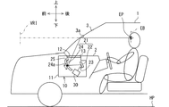
図1に示すように、本開示の第1実施形態による虚像表示装置は、車両1に用いられ、当該車両1のインストルメントパネル2内に収容されるヘッドアップディスプレイ装置(以下、HUD装置)10である。HUD装置10は、車両1のウインドシールド3に設けられた投影部3aへ向けて画像の表示光を投影する。これにより、HUD装置10は、画像を、視認者としての乗員により視認可能な虚像VRIとして表示する。すなわち、投影部3aにて反射される画像の表示光が車両1の室内に設定された視認領域EBに到達することにより、視認領域EBにアイポイントEPが位置する乗員は、各種情報を認識することができる。
(First Embodiment)
As shown in FIG. 1, the virtual image display device according to the first embodiment of the present disclosure is used in the vehicle 1, and the head-up display device (hereinafter, HUD device) 10 housed in the
表示される各種情報としては、例えば車速、燃料残量等の車両1の状態を表す情報、又は視界補助情報、道路情報等のナビゲーション情報が挙げられる。 Examples of the various information to be displayed include information indicating the state of the vehicle 1 such as vehicle speed and remaining fuel amount, and navigation information such as visibility assist information and road information.
以下において、特に断り書きがない限り、前、後、上、下、左及び右が示す各方向は、水平面HP上の車両1を基準として記載される。 In the following, unless otherwise specified, each direction indicated by front, rear, up, down, left and right is described with reference to vehicle 1 on the horizontal plane HP.
車両1のウインドシールド3は、例えばガラスないし合成樹脂により透光性の板状に形成された透過部材であり、インストルメントパネル2よりも上方に配置されている。ウインドシールド3は、前方から後方へ向かう程、インストルメントパネル2とは離間するように傾斜して配置されている。ウインドシールド3は、画像の表示光が投影される投影部3aを、滑らかな凹面状又は平面状に形成している。なお、投影部3aは、ウインドシールド3に設けられていなくてもよい。例えば車両1と別体となっているコンバイナを車両1内に設置して、当該コンバイナに投影部3aが設けられていてもよい。
The
視認領域EBは、HUD装置10により表示される虚像VRIが所定の規格を満たすように(例えば虚像VRI全体が所定の輝度以上となるように)視認可能となる空間領域であって、アイボックスとも称される。視認領域EBは、典型的には、車両1に設定されたアイリプスと重なるように設定される。アイリプスは、両眼それぞれに対して設定され、乗員のアイポイントEPの空間分布を統計的に表したアイレンジに基づいて、楕円体状の仮想的な空間として設定されている。
The viewing area EB is a spatial area that can be visually recognized so that the virtual image VRI displayed by the
このようなHUD装置10の具体的構成を、以下に説明する。HUD装置10は、ハウジング11、表示器30、及び導光部21等により構成されている。
A specific configuration of such a
ハウジング11は、例えば合成樹脂ないし金属等により、表示器30及び導光部21等を収容する中空形状を呈しており、車両1のインストルメントパネル2内に設置されている。ハウジング11は、投影部3aと対向する上面部に、光学的に開口する窓部12を有している。窓部12は、例えば表示光を透過可能な防塵シート13で覆われている。
The
表示器30は、表示画面33に画像を表示し、その画像の表示光を導光部21へ向けて投射する。本実施形態の表示器30は、透過型の液晶表示器となっている。表示器30は、画像表示素子31及びバックライトユニット41を有し、例えば遮光性を有する箱状のケーシングにこれらを収容しつつ、表示画面33をケーシングの外部に露出させて構成されている。
The
導光部21は、表示器30の表示画面33から発せられた表示光を導光する光路を形成している。導光部21は、例えば平面鏡22及び凹面鏡24を有している。導光部21の合成焦点距離における符号は、正である。
The
平面鏡22は、例えば合成樹脂ないしガラスからなる基材の表面に、アルミニウムを蒸着させること等により、反射面23を形成している。平面鏡22の反射面23は、滑らかな平面状に形成されている。表示器30から平面鏡22に入射した表示光は、その反射面23により凹面鏡24へ向けて反射される。
The
凹面鏡24は、例えば合成樹脂ないしガラスからなる基材の表面に、アルミニウムを蒸着させること等により、反射面25を形成している。凹面鏡24の反射面25は、凹状に湾曲することで、滑らかな凹面状に形成されている。平面鏡22から凹面鏡24に入射した表示光は、その反射面23により投影部3aへ向けて反射される。ここで、正の光学パワーを有する凹面鏡24の反射面25での反射によって、虚像VRIを表示画面33上の画像に対して拡大することが可能となっている。
The
こうして凹面鏡24に反射された表示光は、防塵シート13を透過することでHUD装置10の外部へ射出され、ウインドシールド3の投影部3aに入射する。投影部3aに反射された表示光が乗員のアイポイントEPに到達すると、当該乗員は虚像VRIを視認可能となるのである。ここで、投影部3aは、透過部材としてのウインドシールド3に設けられているので、虚像VRIは、ウインドシールド3を通して視認される車外の景色と重畳して表示される。
The display light reflected by the
また、凹面鏡24は、ステッピングモータの駆動に応じて、左右方向に伸びる回転軸24aのまわりに回動可能となっている。こうした回動によって、虚像VRIの表示位置を上下方向に変位するように調整することができる。
Further, the
以下では、本実施形態の表示器30について詳細に説明する。図2,3に示すように、表示器30の画像表示素子31は、薄膜トランジスタ(Thin Film Transistor;TFT)を用いたTFT液晶パネルであって、例えば2次元配列にて配列された複数の液晶画素を形成しているアクティブマトリクス型の液晶パネルである。
Hereinafter, the
画像表示素子31は、長手方向LD及び短手方向SDを有する矩形状、すなわち長方形状を呈している。液晶画素が長手方向LD及び短手方向SDに配列されることで、導光部21側を向き、画像の表示光を射出する表示画面33もまた短手方向SDの寸法に対して長手方向LDの寸法が大きく設定された長方形状を呈している。
The
表示画面33の長手方向LDは、視認される虚像VRIの左右方向に対応し、表示画面33の短手方向SDは、視認される虚像VRIの上下方向に対応している。こうして虚像VRIは、左右方向に長い横長に表示されることが可能となる。
The longitudinal LD of the
画像表示素子31の本体を挟んで表示画面33とは反対側の面は、バックライトユニット41の光源光により照明される照明対象面32となっている。照明対象面32も、表示画面33の形状に合わせた形状、詳細に、短手方向SDの寸法に対して長手方向LDの寸法が大きく設定された長方形状を呈している。
The surface of the
画像表示素子31は、一対の偏光板及び一対の偏光板に挟まれた液晶層等が積層されて形成されていることで、平板状を呈している。各偏光板は、互いに直交する透過軸及び吸収軸を有し、透過軸方向に偏光した光を透過させ、吸収軸方向に偏光した光を吸収する性質を有する。一対の偏光板は、透過軸を互いに直交させて配置されている。液晶層は、液晶画素毎の電圧の印加により、印加電圧に応じて液晶層に入射する光の偏光方向を回転させることが可能となっている。こうして画像表示素子31は、偏光方向の回転により、導光部21側の偏光板を透過する光の割合、すなわち透過率を、液晶画素毎に変えることができる。
The
したがって、画像表示素子31は、照明対象面32を介した光源光の入射に対応して、液晶画素毎の透過率が制御されることで、当該光源光を利用して表示画面33に画像を表示する。隣り合う液晶画素には、互いに異なる色(例えば赤、緑及び青)のカラーフィルタが設けられており、これらの組み合わせにより、様々な色が再現されるようになっている。
Therefore, the
各液晶画素では、表示画面33及び照明対象面32間を貫通するように、面32,33の法線方向に光学的に開口して設けられる透過部と、当該透過部を囲んで形成された配線部とが設けられている。したがって、各透過部が光学的な小開口部を構成している。さらに、表示画面33及び照明対象面32の外周が遮光部材に囲まれていることで、表示画面33と照明対象面32とに挟まれた部位が光学的な大開口部として機能している。
Each liquid crystal pixel is formed by surrounding a transmissive portion provided by optically opening in the normal direction of the
バックライトユニット41は、光源光を照明対象面32へ照射する。具体的に、バックライトユニット41は、光源部42、第1レンズ部材46、第2レンズ部材50、第3レンズ部材56、及び拡散板61等により構成されている。第1レンズ部材46、第2レンズ部材50、第3レンズ部材56、及び拡散板61は、光源部42と画像表示素子31の照明対象面32との間の光路上に配置されている。
The
光源部42は、複数の光源素子43を光源用回路基板44上に配列して形成されている。本実施形態の光源素子43には、例えば点状光源としての発光ダイオード素子が採用されている。各光源素子43は、光源用回路基板44上の配線パターンを通じて、電源と電気的に接続されている。より詳細に、各光源素子43は、チップ状の青色発光ダイオードを、透光性を有する合成樹脂に黄色蛍光剤を混合した黄色蛍光体により封止することにより形成されていれる。青色発光ダイオードから電流量に応じて発せられる青色光により、黄色蛍光体が励起されて黄色光が発光され、青色光と黄色光との混合により、結果的に、各光源素子43から白色(より詳細には疑似白色)の光源光が発光される。
The
ここで各光源素子43は、発光強度が最大となる強度ピーク方向PDから乖離するに従って発光強度が相対的に低下する放射角度分布にて、光源光を発光する。各光源素子43の強度ピーク方向PDは、互いに実質同一の方向であり、光源用回路基板44の表面(これを光源配置面44aと称する)に対して実質垂直な方向となっている。
Here, each
光源配置面44a上において、複数の光源素子43は、短手対応方向及び長手対応方向のうち、少なくとも長手対応方向に所定の間隔INTだけずれて配置されるように、互いに並べられている。
On the light
ここで、短手対応方向とは、表示画面33又は照明対象面32を、強度ピーク方向PDの逆方向に沿って射影対象に射影した場合に、表示画面33又は照明対象面32上の短手方向SDを示すベクトルが射影対象上に射影されたベクトルによって示される方向を意味する。同様に、長手対応方向とは、表示画面33又は照明対象面32を、強度ピーク方向PDの逆方向に沿って射影対象に射影した場合に、表示画面33又は照明対象面32上の長手方向LDを示すベクトルが射影対象上に射影されたベクトルによって示される方向を意味する。ここでは、光源配置面44aが射影対象である。以下、短手対応方向をY方向YD、長手対応方向をX方向XDと称する。
Here, the short-handed direction is the short-handed direction on the
光源配置面44aと表示画面33及び照明対象面32とが平行に配置されていれば、図2,3のように、短手方向SDとY方向YDとは一致し、長手方向LDと方向とX方向XDとは、一致する。光源配置面44aに対して表示画面33及び照明対象面32が傾斜して配置されていれば、その傾斜に対応して、短手方向SDとY方向YDとはずれる場合があり、長手方向LDとX方向XDとがずれる場合がある。
If the light
特に本実施形態では、複数の光源素子43は、X方向XDに沿って、1列に配列されている。各光源素子43間の間隔INTは、互いに実質等しく設定されている。各光源素子43から発光された光源光は、第1レンズ部材46へと入射する。
In particular, in the present embodiment, the plurality of
図2,3に示す第1レンズ部材46は、例えば合成樹脂ないしガラスにより、透光性に形成され、光源光を屈折可能な光学面46a,46bを有している。第1レンズ部材46は、各光源素子43に1対1で個別に対応するように設けられた平行化レンズ素子48を、光源配置面44a上の光源素子43の配置に合わせて並べた平行化部47を有している。各平行化レンズ素子48は、対応する光源素子43と対向して配置され、各光源素子43から発せられる光源光を集光して平行化する。ここでいう平行化とは、光源光を光源素子43から射出された直後の状態よりも平行光束に近づけていればよく、光源光を完全な平行光束にするものに限られない。
The
また、本実施形態では、各平行化レンズ素子48の光軸に対して、当該平行化レンズ素子48に個別に対応する光源素子43を、X方向XDでの光源部42中心側に僅かに偏心させた配置が採用されている。換言すると、X方向XDにて、平行化レンズ素子48間の間隔は、光源素子43間の間隔INTよりも僅かに大きく設定されている。
Further, in the present embodiment, the
本実施形態の第1レンズ部材46は、光源部42側に平面状の光学面46aを形成している。また第1レンズ部材46は、光源部42とは反対側、すなわち照明対象面32側に、滑らかな凸面状の面が複数並んだ光学面46bを、平行化部47として形成している。平行化レンズ素子48の焦点距離における符号は、正であり、その値は平行化レンズ素子48と光源素子43との間の距離に近くなるように設定される。こうして第1レンズ部材46により平行化された光源光は、第2レンズ部材50へと入射する。
The
図2〜4に示す第2レンズ部材50は、例えば合成樹脂ないしガラスにより、透光性に形成され、光源光を屈折可能な光学面50a,50bを有している。第2レンズ部材50は、第1レンズ部材46側(換言すると光源部42側)の光学面50aに、小光源アレイレンズ部51を有すると共に、第3レンズ部材56側(換言すると照明対象面32側)の光学面50bに、短手集光部53を有している。
The
小光源アレイレンズ部51は、複数の小光源レンズ素子52を配列して形成されている。各小光源レンズ素子52は、光源素子43が並べられた間隔INTよりも十分に小さな微小ピッチPIT(例えば3mm以下)にて配列され、互いに隙間なく敷き詰められている。特に本実施形態の小光源レンズ素子52は、Y方向YD及びX方向XDの2方向に、矩形格子状に配列されている。
The small light source
各小光源レンズ素子52は、互いに共通の焦点距離fax,fayを有している。各小光源レンズ素子52の焦点距離fax,fayの絶対値は、他の焦点距離fbx,fby,fcx,fcy,fdx,fdyの絶対値よりも十分に小さく設定されている。
Each small light
こうした形態により、各小光源レンズ素子52は、光源部42から平行化部47を経て平行化された光源光を分割して、新たな点状の小光源を構成するように振る舞っている。すなわち、図5に示すように、各小光源レンズ素子52が入射する光源光を収束又は発散されることによって、各小光源レンズ素子52の近傍に小光源の像点IPx,IPyが構成される。こうした仮想的ともいえる小光源の像点IPx,IPyが小さなピッチPITで配列されているので、小光源アレイレンズ部51は、全体として、仮想的な面状光源をつくり出すように機能している。
In such a form, each small light
特に本実施形態では、各小光源レンズ素子52は、第1レンズ部材46側(換言すると光源部42側)に凸となるトロイダル面状に形成されている。こうした面形状によって、各小光源レンズ素子52において、Y方向YDの焦点距離fayの絶対値は、X方向XDの焦点距離faxの絶対値よりも小さく設定されている。したがって、各小光源において、Y方向YDにおける像点IPyの位置(より詳細に、錯乱円のY方向YDの寸法を最小とする位置)は、X方向XDにおける像点IPxの位置(より詳細に、錯乱円のX方向XDの寸法を最小とする位置)と、光源光の進行方向に前後するようにずれている。そして、各小光源から発せられる分割光源光において、Y方向YDの拡がり角βは、X方向XDの拡がり角αに対して大きな状態となる。換言すると、各小光源レンズ素子52において、Y方向YDのF値は、X方向XDのF値よりも小さい。
In particular, in the present embodiment, each small light
なお、上記像点IPx,IPyの位置は、小光源アレイレンズ部51よりも照明対象面32側に配置された光学要素の影響を考慮しない小光源アレイレンズ部51単独の機能として定まる位置である。すなわち、画像表示素子31側から第3レンズ部材56等を通してみた像点IPx,IPyの位置は、前述の光学要素の倍率の影響を受ける。
The positions of the image points IPx and IPy are determined as a function of the small light source
なお、図2〜4では、小光源レンズ素子52の一部にのみ符号が付されている。図2〜4の小光源レンズ素子52は、模式的に図示されており、現実にはより微小なサイズとなっている。
In FIGS. 2 to 4, only a part of the small light
短手集光部53は、小光源の各方向XD,YDでの像点IPx,IPyの位置よりも照明対象面32側に配置された光学面50bとして構成されている。短手集光部53は、各小光源からの分割光源光をまとめて屈折可能な単一の面状に形成されている。短手集光部53は、各分割光源光を、Y方向YD及びX方向XDのうち、少なくともY方向YDに集光するように構成されている。
The short
具体的に本実施形態では、短手集光部53は、第3レンズ部材56側(換言すると照明対象面32側)に凸となり、Y方向YDに湾曲する凸シリンドリカル面状に形成されている。短手集光部53のY方向YDの焦点距離fbyにおける符号は、正である。
Specifically, in the present embodiment, the short
こうして第2レンズ部材50にて、小光源に分割され、さらに集光された光源光は、第3レンズ部材56へと入射する。
In this way, the light source light divided into small light sources by the
図2〜4に示す第3レンズ部材56は、例えば合成樹脂ないしガラスにより、透光性に形成され、光源光を屈折可能な光学面56a,56bを有している。第3レンズ部材56は、第2レンズ部材50側(換言すると光源部42側)の光学面56aに、長手指向性調整部58を有すると共に、拡散板61側(換言すると照明対象面32側)の光学面56bに、短手指向性調整部59を有している。本実施形態では、長手指向性調整部58及び短手指向性調整部59を合わせて、単に指向性調整部57と称する。
The
長手指向性調整部58は、小光源アレイレンズ部51を経た光源光について、X方向XDの指向性を調整する。具体的に、長手指向性調整部58は、第2レンズ部材50側(換言すると光源部42側)から、その反対側へ凹み、X方向XDに湾曲する凹シリンドリカル面状に形成されている。特に本実施形態の長手指向性調整部58による光学面56aは、フレネルレンズ状にX方向XDに分割されることで、Y方向YDに延伸する短冊状の分割光学面の集合体となっている。長手指向性調整部58のX方向XDの焦点距離fcxにおける符号は、負である。こうして、長手指向性調整部58は、光源光をX方向XDに発散することで、X方向XDの指向性を調整している。長手指向性調整部58での発散調整により、視認領域EBを乗員の眼が並ぶ左右方向へ拡大することができる。
The longitudinal
短手指向性調整部59は、小光源アレイレンズ部51を経た光源光について、Y方向YDの指向性を調整する。具体的に、短手指向性調整部59は、拡散板61側(換言すると照明対象面32側)に凸となり、Y方向YDに湾曲する凸シリンドリカル面状に形成されている。短手指向性調整部59のY方向YDの焦点距離fdyにおける符号は、正である。こうして、短手指向性調整部59は、光源光をY方向YDに集光することで、Y方向YDの指向性を調整している。短手指向性調整部59での集光調整により、乗員の眼が並んでいない上下方向に視認領域EBを過度に拡大することなくコンパクト化して虚像VRIの輝度を高めることができる。
The short-hand
こうして第3レンズ部材56にて指向性が調整された光源光は、拡散板61へと入射する。図2,3に示す拡散板61は、照明対象面32に近接状態又は接着状態となるように配置され、例えば透光性の合成樹脂からなる基材にマイクロビーズ等の拡散粒子を混合することにより、シート状又は板状に形成されている。拡散板61は、第3レンズ部材56側から入射した光源光を拡散して照明対象面32を照明する。
The light source light whose directivity is adjusted by the
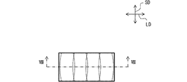
図2,6に示すように、表示器30の短手方向SDないしY方向YDに沿った縦断面上でみると、各小光源からの分割光源光は、照明対象面32に到達するまでに、当該照明対象面32の短手方向SDの寸法まで拡張される。照明対象面32の短手方向SDにおける両端部間に、各小光源からの分割光源光が重ね合される。すなわちY方向YDでは各分割光源光がインテグレートされて、全体照明が実施される。
As shown in FIGS. 2 and 6, when viewed on the vertical cross section of the
他方、図3,6に示すように、表示器30の長手方向LDないしX方向XDに沿った縦断面上でみると、各小光源からの分割光源光は、照明対象面32に到達するまでに、当該照明対象面32の長手方向LDの寸法まで拡張されない。分割光源光の到達時の拡張幅は、例えば、各光源素子43間の間隔INT以上であって、当該間隔INTの2倍以下の範囲に抑制される。各分割光源光は、照明対象面32のうち、互いにX方向XDにずれた照明範囲を照明する。すなわちX方向XDでは各分割光源光のインテグレートが規制されており、部分照明が実施される。
On the other hand, as shown in FIGS. 3 and 6, when viewed on the vertical cross section of the
Y方向YDのインテグレートよりもX方向XDのインテグレートが規制されている態様、すなわちY方向YDのみインテグレータ光学系となっている態様では、図7に模式的に示すように、各小光源からの分割光源光が短手方向SDに大きく引き伸ばされたように照明される。このため、各分割光源光の重なり部分も短手方向SDに引き延ばされたようになる。故に、短手方向SDでの照明強度の勾配が抑制されることは勿論、長手方向LDにおいても、図8に模式的に示すように照明強度の均一化が図られる。 In the embodiment in which the integration of the X-direction XD is regulated rather than the integration of the Y-direction YD, that is, in the embodiment in which only the Y-direction YD is an integrator optical system, as shown schematically in FIG. 7, the division from each small light source is performed. The light source is illuminated as if it were greatly stretched in the short direction SD. Therefore, the overlapping portion of the light of each divided light source is also stretched in the lateral SD direction. Therefore, not only the gradient of the illumination intensity in the lateral SD is suppressed, but also in the longitudinal direction LD, the illumination intensity can be made uniform as schematically shown in FIG.
ここで図4を参照して、短手集光部53と短手指向性調整部59との焦点距離の設定及び関係について、説明する。まず、短手集光部53におけるY方向YDの焦点距離fbyの絶対値及び短手指向性調整部59におけるY方向YDの焦点距離fdyの絶対値は、各小光源レンズ素子52におけるY方向YDの焦点距離fayの絶対値よりも十分に大きく設定される。また、短手集光部53におけるY方向YDの焦点距離fby及び短手指向性調整部59におけるY方向YDの焦点距離fdyは、短手集光部53と短手指向性調整部59との間の距離Dよりも大きく設定される。さらには、短手指向性調整部59におけるY方向YDの焦点距離fdyは、短手集光部53におけるY方向YDの焦点距離fbyよりも大きく設定される。
Here, with reference to FIG. 4, the setting and relationship of the focal length between the short-
このようにすることで、各小光源からの分割光源光は、Y方向YDにおいて、短手指向性調整部59よりも照明対象面32に近い位置で重ね合わせ状態を構成する。さらには、導光部21の凹面鏡24が表示光を集光する構成に適合した指向性を以って、照明を実施することができる。
By doing so, the divided light source light from each small light source constitutes a superposed state at a position closer to the
以下、焦点距離及びレンズ配置の具体例を示す。図4の例において、各小光源レンズ素子52のX方向XDの焦点距離faxは、2.03mmである。各小光源レンズ素子52のY方向YDの焦点距離fayは、1.22mmである。短手集光部53のX方向XDの焦点距離fbxは、実質無限大である。短手集光部53のY方向YDの焦点距離fbyは、37.74mmである。長手指向性調整部58のX方向XDの焦点距離fcxは、−152mmである。長手指向性調整部58のY方向YDの焦点距離fcyは、実質無限大である。短手指向性調整部59のX方向XDの焦点距離fdxは、実質無限大である。短手指向性調整部59のY方向YDの焦点距離fdyは、42.05mmである。また、距離Dに近似可能な第2レンズ部材50と第3レンズ部材56との距離は、23mmである。
Hereinafter, specific examples of the focal length and the lens arrangement will be shown. In the example of FIG. 4, the focal length fax in the X direction XD of each small light
(作用効果)
以上説明した第1実施形態の作用効果を以下に改めて説明する。
(Action effect)
The effects of the first embodiment described above will be described again below.
第1実施形態によると、小光源アレイレンズ部51は、複数の小光源レンズ素子52を配列して形成されている。こうした小光源レンズ素子52は、光源素子43の間隔INTよりも小さなピッチPITで配列され、光源部42からの光源光を分割して小光源を構成するように振る舞う。すなわち、小光源が小さなピッチPITでY方向YDに配列されることにより、線状光源ないし面状光源のように小光源アレイレンズ部51が機能し、それは、X方向XDにずれて並べられた複数の光源素子43により、X方向XDに幅をもった光源のように振る舞う。
According to the first embodiment, the small light source
これに対して、各小光源レンズ素子52にて、Y方向YDの焦点距離fayの絶対値は、X方向XDの焦点距離faxの絶対値より小さくされている。この焦点距離fax,fayの関係により、小光源レンズ素子52の各小光源から発せられるY方向YDの分割光源光の拡がり角βが比較的広角になるため、光源光を短い光路長で好適に拡げることが可能となり、照明対象面32の短手方向SDの寸法に合わせた照明を実現できる。Y方向YDに対してX方向XDでは、小光源レンズ素子52による各小光源から発せられるX方向XDの分割光源光の拡がり角αが比較的挟角になるものの、既に小光源アレイレンズ部51がX方向XDに幅をもった光源のように振る舞っている。故に、各々の小光源からの分割光源光を、照明対象面32の長手方向LDの寸法まで拡げずとも、照明対象面32の長手方向LDの寸法に合わせた照明を実現することができる。したがって、より幅広の範囲を照明すべきX方向XDに合わせた長い光路長を設定する必要性を低減できる。
On the other hand, in each small light
以上により、虚像VRIの輝度ムラ発生を低減して虚像VRIの視認性を高めつつ、体格増大を抑制したHUD装置10を提供することができる。
As described above, it is possible to provide the
また、第1実施形態によると、各小光源レンズ素子52は、Y方向YD及びX方向XDに配列され、トロイダル面状に形成されている。トロイダル面状の小光源レンズ素子52が2方向に配列されることにより、2次元的に多数の小光源を構成することが可能となり、小光源アレイレンズ部51を輝度ムラの少ない面状光源のように機能させることができる。
Further, according to the first embodiment, each small light
また、第1実施形態によると、照明対象面32に入射する分割光源光は、Y方向YDではインテグレートされ、X方向XDではY方向YDよりもインテグレートを規制される。照明対象面32の長手方向LDの寸法までX方向XDに分割光源光を拡張する必要がないので、Y方向YDでのインテグレートに合わせた光路長を設定可能となる。故に、バックライトユニット41の光路長が短縮可能となるので、装置10の体格増大を抑制できる。
Further, according to the first embodiment, the divided light source light incident on the
また、第1実施形態によると、短手集光部53は、光路上において、各小光源レンズ素子52よりも照明対象面32側に配置され、分割光源光をまとめてY方向YDに集光するように構成されている。こうした短手集光部53による集光によって、各小光源レンズ素子52からの分割光源光が照明対象面32へ向かうようになり、当該照明対象面32での適切な重ね合わせが実現される。
Further, according to the first embodiment, the short
また、第1実施形態によると、小光源アレイレンズ部51が光源部42側に配置された光学面50aを構成すると共に、短手集光部53が照明対象面32側に配置された光学面50bを構成することにより、小光源アレイレンズ部51と短手集光部53とが第2レンズ部材50として一体的に形成されている。このようにすると、小光源アレイレンズ部51と短手集光部53との間の位置合わせの精度、延いては照明の精度を高めることができ、透過率も向上できる。同時に、部品点数を抑制できるので、装置10の体格拡大を抑制できる。
Further, according to the first embodiment, the small light source
また、第1実施形態によると、指向性調整部57は、短手集光部53と照明対象面32との間の光路上に配置され、小光源アレイレンズ部51を経て入射した光源光の指向性を調整する。短手集光部53によりも照明対象面32に近い位置、すなわち各分割光源光の重ね合わせ状態が醸成されつつある位置で、視認領域EBを形成するための指向性が調整される。バックライトユニット41に照明対象面32への照明ムラ抑制効果を発揮させつつ、視認領域EBを適切な範囲とすることができる。この結果、虚像VRIの視認性が高まる。
Further, according to the first embodiment, the
また、第1実施形態によると、指向性調整部57は、Y方向YDに光源光を集光すると共に、X方向XDに光源光を発散させる。発散作用を受けた方向に視認領域EBが拡大されるので、視認領域EBの長手方向と、画像の長手方向LDを一致させることができる。このため、両眼の並び方向を視認領域EBの長手方向を合わせた場合に、両眼視し易く、かつ横長の見易い虚像VRIを実現することができる。この結果、虚像VRIの視認性が高まる。
Further, according to the first embodiment, the
また、第1実施形態によると、短手集光部53のY方向YDの焦点距離fbyは、指向性調整部57のY方向YDの焦点距離fdyよりも小さく、かつ、短手集光部53と指向性調整部57との間の距離Dよりも大きい。こうした条件を満たすことにより、指向性調整部57よりも照明対象面32側で分割光源光の重ね合わせ状態が実現される。
Further, according to the first embodiment, the focal length fby of the Y-direction YD of the short-
(第2実施形態)
図9に示すように、第2実施形態は第1実施形態の変形例である。第2実施形態について、第1実施形態とは異なる点を中心に説明する。
(Second Embodiment)
As shown in FIG. 9, the second embodiment is a modification of the first embodiment. The second embodiment will be described focusing on the differences from the first embodiment.
第2実施形態の第2レンズ部材250においても小光源アレイレンズ部251は、第1実施形態と同様に、複数の小光源レンズ素子252を配列して形成されている。各小光源レンズ素子252は、光源素子43が並べられた間隔INTよりも十分に小さなピッチPIT(例えば3mm以下)にて配列され、互いに隙間なく敷き詰められている。ただし、第2実施形態の小光源レンズ素子252は、Y方向YDの1方向に配列されている。このように、小光源レンズ素子252は、Y方向YD及びX方向XDのうち、分割光源光がインテグレートされるY方向YDに配列されていればよい。
Also in the
各小光源レンズ素子252は、X方向XDに延伸した短冊状を呈しており、第1レンズ部材46側(換言すると光源部42側)に凸となる凸シリンドリカル面状に形成されている。こうしたシリンドリカル面の小光源レンズ素子252では、X方向XDの焦点距離faxは、実質無限大である。故に、第1実施形態と同様に、各小光源レンズ素子252において、Y方向YDの焦点距離fayの絶対値がX方向XDの焦点距離faxの絶対値よりも小さいという関係が成立している。こうした第2実施形態では、各小光源レンズ素子252が構成する小光源は、線状光源のようになる。
Each small light
以上説明した第2実施形態によると、各小光源レンズ素子252は、Y方向YDに配列され、シリンドリカル面状に形成されている。シリンドリカル面状の小光源レンズ素子252がY方向YDに配列されることにより、Y方向YDの焦点距離fayの絶対値とX方向XDの焦点距離faxの絶対値の差を大きくできる。したがって、Y方向YDに対して最適な光路長と、X方向XDに対して最適な光路長との差を縮めることが可能となる。故に、バックライトユニット41の光路長を、両方向XD,YD共に適切な光路長に設定することが容易となるので、虚像VRIの視認性を高めつつ、体格増大を抑制したHUD装置10を提供することができる。
According to the second embodiment described above, each small light
(他の実施形態)
以上、複数の実施形態について説明したが、本開示は、それらの実施形態に限定して解釈されるものではなく、本開示の要旨を逸脱しない範囲内において種々の実施形態及び組み合わせに適用することができる。
(Other embodiments)
Although the plurality of embodiments have been described above, the present disclosure is not construed as being limited to those embodiments, and is to be applied to various embodiments and combinations without departing from the gist of the present disclosure. Can be done.
具体的に変形例1としては、図10,11に示すように、小光源アレイレンズ部51と、短手集光部53とは、別体にてそれぞれ形成されていてもよい。
Specifically, as a modification 1, as shown in FIGS. 10 and 11, the small light source
変形例2としては、各小光源レンズ素子52のX方向XDの焦点距離faxにおける符号及びY方向YDの焦点距離fayにおける符号のうち少なくとも一方は、負であってもよい。
As the second modification, at least one of the sign in the focal length fax in the X direction XD and the sign in the focal length fair in the Y direction YD of each small light
変形例3としては、光源部42は、少なくともX方向XDに所定の間隔だけずれて、互いに並べられた光源素子43を含むものであればよい。複数の光源素子43がX方向XDに沿って一直線上に並べられていなくてもよい。具体例としては、複数の光源素子43は、X方向XDに所定の間隔だけずれると共に、Y方向YDにも光源素子43毎に異なる値だけオフセットされていることで、曲線状に並べられていてもよい。また、複数の光源素子43がX方向XDに所定の間隔だけずれると共に、Y方向YDにも交互に逆方向にオフセットされていることで、ジグザグに並べられていてもよい。
As a
変形例4としては、光源部42は、少なくともX方向XDに所定の間隔INTだけずれて、互いに並べられた光源素子43を含むものであればよい。複数の光源素子43が2次元に配列されていれば、X方向XDに互いにずれる光源素子43の組み合わせが発生する。具体例としては、複数の光源素子43がY方向YD及びX方向XDの2方向に矩形格子状に配列されていてもよい。また、複数の光源素子43は、三角格子状、六角格子状等に配列されていてもよい。
As a modification 4, the
変形例5としては、光源素子43がずれる所定の間隔INTは、変調していてもよい。この場合、小光源レンズ素子52が配列されるピッチPITは、間隔INTの平均値である平均間隔よりも小さければよい。ただし、ピッチPITが各間隔INTのうち最小値である最小間隔よりも小さくなっていることがより好適である。
As a modification 5, the predetermined interval INT in which the
変形例6としては、光源素子43には、点状光源に限られず、線状光源又は面状光源が採用されてもよい。光源部42は、例えばY方向YDに延伸する線状光源としての光源素子43を、X方向XDに複数並べた構成であってもよい。また、光源部42は、面状光源としての光源素子43を、X方向XDに互いに離間するように複数並べた構成であってもよい。
As the modification 6, the
変形例7としては、導光部21は、平面鏡22の代わりに、又は新たな光学素子の追加によって、凸面鏡を有していてもよい。導光部21に凸面鏡が含まれる場合であっても、導光部21の合成焦点距離における符号は、正であることが好ましい。この構成においては、短手集光部53のY方向YDの焦点距離fbyは、短手指向性調整部59のY方向YDの焦点距離fdyと実質的に等しい値に設定されてもよい。
As a modification 7, the
変形例8としては、拡散板61は、第2レンズ部材50と第3レンズ部材56との間に配置されていてもよい。
As a modification 8, the
変形例9としては、長手指向性調整部58は、フレネルレンズ状ではなく、単一の凹シリンドリカル面状に形成されていてもよい。逆に、短手指向性調整部59は、フレネルレンズ状に形成されていてもよい。また、図10,11に示すように、長手指向性調整部58及び短手指向性調整部59の少なくとも一部は、トロイダル面等の1つの光学面により合成状態にて構成されていてもよい。さらには、長手指向性調整部58及び短手指向性調整部59のうち少なくとも一方が設けられていなくてもよい。
As a modification 9, the longitudinal
変形例10としては、バックライトユニット41の照明対象として機能する照明対象部としての照明対象面32は、長方形状に限られず、楕円形状、平行四辺形状等に形成されていてもよい。また、照明対象部は、単一の面状に形成されていなくてもよく、3次元的な構造を含んでいてもよい。
As a
変形例11としては、虚像表示装置は、航空機、船舶、あるいはゲーム筐体等の移動しない筐体等の各種の乗り物に適用することができる。また、虚像表示装置は、ヘッドマウントディスプレイ等の携帯情報端末に適用することができる。
As a
3a:投影部、10:HUD装置(虚像表示装置)、31:画像表示素子、32:照明対象面(照明対象部)、41:バックライトユニット、42:光源部、43:光源素子、51:小光源アレイレンズ部、52:小光源レンズ素子、SD:短手方向、LD:長手方向、YD:Y方向(短手対応方向)、XD:X方向(長手対応方向)、INT:間隔、PIT:ピッチ 3a: Projection unit, 10: HUD device (imaginary image display device), 31: Image display element, 32: Illumination target surface (illumination target unit), 41: Backlight unit, 42: Light source unit, 43: Light source element, 51: Small light source array lens unit, 52: Small light source lens element, SD: Short direction, LD: Longitudinal direction, YD: Y direction (short corresponding direction), XD: X direction (longitudinal correspondence direction), INT: Spacing, PIT :pitch
Claims (7)
短手方向(SD)の寸法に対して長手方向(LD)の寸法が大きく設定された照明対象部(32)を有し、前記照明対象部に照明された光源光を利用して前記画像を表示する画像表示素子(31)と、
前記光源光を前記照明対象部へ照射するバックライトユニット(41)と、を備え、
前記バックライトユニットは、
前記短手方向に対応する短手対応方向(YD)及び前記長手方向に対応する長手対応方向(XD)のうち少なくとも前記長手対応方向に所定の間隔(INT)だけずれて、互いに並べられた複数の光源素子(43)を有し、各前記光源素子から前記光源光を発する光源部(42)と、
前記光源部と前記照明対象部との間の光路上に配置され、前記短手対応方向及び前記長手対応方向のうち少なくとも前記短手対応方向に沿って、前記間隔よりも小さなピッチ(PIT)で配列された複数の小光源レンズ素子(52)を有し、各前記小光源レンズ素子が前記光源部からの前記光源光を分割して新たな小光源を構成するように振る舞う小光源アレイレンズ部(51)と、を有し、
各前記小光源レンズ素子において、前記短手対応方向の焦点距離の絶対値は、前記長手対応方向の焦点距離の絶対値よりも小さく、
前記バックライトユニットは、
前記光路上において、各前記小光源レンズ素子よりも前記照明対象部側に、各前記小光源レンズ素子により分割された各前記光源光をまとめて前記短手対応方向に集光するように構成された短手集光部(53)と、
前記短手集光部と前記照明対象部との間の前記光路上に配置され、前記小光源アレイレンズ部を経て入射した前記光源光の指向性を調整する指向性調整部(57)と、をさらに有し、
前記指向性調整部は、前記短手対応方向に前記光源光を集光すると共に、前記長手対応方向に前記光源光を発散させる虚像表示装置。 A virtual image display device that displays a virtual image (VRI) by projecting the display light of an image onto a projection unit (3a).
It has an illuminated object portion (32) in which the dimension in the longitudinal direction (LD) is set larger than the dimension in the lateral direction (SD), and the image is obtained by using the light source light illuminated on the illuminated object portion. The image display element (31) to be displayed and
A backlight unit (41) that irradiates the illumination target portion with the light source light is provided.
The backlight unit is
A plurality of the short-side corresponding directions (YD) corresponding to the short-side direction and the longitudinal-corresponding direction (XD) corresponding to the longitudinal direction, which are arranged with each other at least by a predetermined interval (INT) in the longitudinal-corresponding direction. A light source unit (42) having a light source element (43) and emitting the light source light from each light source element.
It is arranged on the optical path between the light source unit and the illumination target unit, and has a pitch (PIT) smaller than the interval along at least the short-side corresponding direction of the short-side corresponding direction and the long-distance corresponding direction. A small light source array lens unit having a plurality of arranged small light source lens elements (52), and each small light source lens element behaves as if the light source light from the light source unit is divided to form a new small light source. (51) and
In each the small light-source lens element, it said absolute value of the focal length of the short side corresponding direction is rather smaller than the absolute value of the focal length of the longitudinal direction corresponding,
The backlight unit is
On the optical path, the light source light divided by the small light source lens element is collectively focused on the illumination target portion side of the small light source lens element in the direction corresponding to the short side. The short light source (53) and
A directivity adjusting unit (57) arranged on the optical path between the short condensing unit and the illuminated target unit and adjusting the directivity of the light source light incident through the small light source array lens unit. Has more,
The directivity adjusting unit is a virtual image display device that collects the light source light in the direction corresponding to the short side and radiates the light source light in the direction corresponding to the longitudinal direction.
短手方向(SD)の寸法に対して長手方向(LD)の寸法が大きく設定された照明対象部(32)を有し、前記照明対象部に照明された光源光を利用して前記画像を表示する画像表示素子(31)と、
前記光源光を前記照明対象部へ照射するバックライトユニット(41)と、を備え、
前記バックライトユニットは、
前記短手方向に対応する短手対応方向(YD)及び前記長手方向に対応する長手対応方向(XD)のうち少なくとも前記長手対応方向に所定の間隔(INT)だけずれて、互いに並べられた複数の光源素子(43)を有し、各前記光源素子から前記光源光を発する光源部(42)と、
前記光源部と前記照明対象部との間の光路上に配置され、前記短手対応方向及び前記長手対応方向のうち少なくとも前記短手対応方向に沿って、前記間隔よりも小さなピッチ(PIT)で配列された複数の小光源レンズ素子(52)を有し、各前記小光源レンズ素子が前記光源部からの前記光源光を分割して新たな小光源を構成するように振る舞う小光源アレイレンズ部(51)と、を有し、
各前記小光源レンズ素子において、前記短手対応方向の焦点距離の絶対値は、前記長手対応方向の焦点距離の絶対値よりも小さく、
前記バックライトユニットは、
前記光路上において、各前記小光源レンズ素子よりも前記照明対象部側に、各前記小光源レンズ素子により分割された各前記光源光をまとめて前記短手対応方向に集光するように構成された短手集光部(53)と、
前記短手集光部と前記照明対象部との間の前記光路上に配置され、前記小光源アレイレンズ部を経て入射した前記光源光の指向性を調整する指向性調整部(57)と、をさらに有し、
前記短手集光部の前記短手対応方向の焦点距離は、前記指向性調整部の前記短手対応方向の焦点距離よりも小さく、かつ、前記短手集光部と前記指向性調整部との間の距離よりも大きい虚像表示装置。 A virtual image display device that displays a virtual image (VRI) by projecting the display light of an image onto a projection unit (3a).
It has an illuminated object portion (32) in which the dimension in the longitudinal direction (LD) is set larger than the dimension in the lateral direction (SD), and the image is obtained by using the light source light illuminated on the illuminated object portion. The image display element (31) to be displayed and
A backlight unit (41) that irradiates the illumination target portion with the light source light is provided.
The backlight unit is
A plurality of the short-side corresponding directions (YD) corresponding to the short-side direction and the longitudinal-corresponding direction (XD) corresponding to the longitudinal direction, which are arranged with each other at least by a predetermined interval (INT) in the longitudinal-corresponding direction. A light source unit (42) having a light source element (43) and emitting the light source light from each light source element.
It is arranged on the optical path between the light source unit and the illumination target unit, and has a pitch (PIT) smaller than the interval along at least the short-side corresponding direction of the short-side corresponding direction and the long-distance corresponding direction. A small light source array lens unit having a plurality of arranged small light source lens elements (52), and each small light source lens element behaves as if the light source light from the light source unit is divided to form a new small light source. (51) and
In each the small light-source lens element, it said absolute value of the focal length of the short side corresponding direction is rather smaller than the absolute value of the focal length of the longitudinal direction corresponding,
The backlight unit is
On the optical path, the light source light divided by the small light source lens element is collectively focused on the illumination target portion side of the small light source lens element in the direction corresponding to the short side. The short light source (53) and
A directivity adjusting unit (57) arranged on the optical path between the short condensing unit and the illuminated target unit and adjusting the directivity of the light source light incident through the small light source array lens unit. Has more,
The focal length of the short-hand condensing unit in the short-hand direction is smaller than the focal length of the directional adjustment unit in the short-hand direction, and the short-hand condensing unit and the directional adjustment unit A virtual image display device that is greater than the distance between.
Priority Applications (2)
| Application Number | Priority Date | Filing Date | Title |
|---|---|---|---|
| JP2019012363A JP6984619B2 (en) | 2019-01-28 | 2019-01-28 | Virtual image display device |
| PCT/JP2019/050528 WO2020158258A1 (en) | 2019-01-28 | 2019-12-24 | Virtual image display device |
Applications Claiming Priority (1)
| Application Number | Priority Date | Filing Date | Title |
|---|---|---|---|
| JP2019012363A JP6984619B2 (en) | 2019-01-28 | 2019-01-28 | Virtual image display device |
Publications (3)
| Publication Number | Publication Date |
|---|---|
| JP2020118935A JP2020118935A (en) | 2020-08-06 |
| JP2020118935A5 JP2020118935A5 (en) | 2020-11-26 |
| JP6984619B2 true JP6984619B2 (en) | 2021-12-22 |
Family
ID=71840902
Family Applications (1)
| Application Number | Title | Priority Date | Filing Date |
|---|---|---|---|
| JP2019012363A Active JP6984619B2 (en) | 2019-01-28 | 2019-01-28 | Virtual image display device |
Country Status (2)
| Country | Link |
|---|---|
| JP (1) | JP6984619B2 (en) |
| WO (1) | WO2020158258A1 (en) |
Families Citing this family (1)
| Publication number | Priority date | Publication date | Assignee | Title |
|---|---|---|---|---|
| JP7406582B2 (en) | 2022-02-16 | 2023-12-27 | ミネベアミツミ株式会社 | Spread lighting device |
Family Cites Families (3)
| Publication number | Priority date | Publication date | Assignee | Title |
|---|---|---|---|---|
| JP6481298B2 (en) * | 2014-09-10 | 2019-03-13 | 日本精機株式会社 | Head-up display device |
| JP6550923B2 (en) * | 2015-05-26 | 2019-07-31 | 日本精機株式会社 | Display device |
| JP2018018706A (en) * | 2016-07-28 | 2018-02-01 | 林テレンプ株式会社 | Luminaire and headup display device |
-
2019
- 2019-01-28 JP JP2019012363A patent/JP6984619B2/en active Active
- 2019-12-24 WO PCT/JP2019/050528 patent/WO2020158258A1/en active Application Filing
Also Published As
| Publication number | Publication date |
|---|---|
| JP2020118935A (en) | 2020-08-06 |
| WO2020158258A1 (en) | 2020-08-06 |
Similar Documents
| Publication | Publication Date | Title |
|---|---|---|
| WO2015012138A1 (en) | Scanning-type projection device | |
| WO2018131444A1 (en) | Head-up display device | |
| JP6481649B2 (en) | Head-up display device | |
| JP6677268B2 (en) | Head-up display device | |
| EP2490070A1 (en) | Illuminating optical system and projector device | |
| JP7172840B2 (en) | virtual image display | |
| JP2014202835A (en) | Illumination device and image display device | |
| JP7087981B2 (en) | Virtual image display device | |
| WO2019049509A1 (en) | Head-up display device and image projection unit | |
| US20070242351A1 (en) | Screen, rear projector, and image display apparatus | |
| US20070297050A1 (en) | Screen, rear projector, projection system, and image display unit | |
| JP6984619B2 (en) | Virtual image display device | |
| WO2017130481A1 (en) | Head up display apparatus and manufacturing method of same | |
| JP2020170067A (en) | Virtual image display device | |
| WO2022130823A1 (en) | Virtual image display device | |
| WO2022014180A1 (en) | Virtual-image display device | |
| US6873470B2 (en) | Arrangement for the visualization of information in a motor vehicle | |
| WO2021182097A1 (en) | Virtual image display device | |
| WO2022019101A1 (en) | Head-up display device and diffusion plate for head-up display | |
| JP7163804B2 (en) | Lighting unit for head-up display | |
| WO2022185927A1 (en) | Spatial floating image display device | |
| WO2022249800A1 (en) | Spatial floating image display device and light source device | |
| JP2008158190A (en) | Illuminating device and projector | |
| JP2022011390A (en) | Virtual image display device | |
| JP2022018830A (en) | Virtual image display device |
Legal Events
| Date | Code | Title | Description |
|---|---|---|---|
| A521 | Request for written amendment filed |
Free format text: JAPANESE INTERMEDIATE CODE: A523 Effective date: 20201016 |
|
| A621 | Written request for application examination |
Free format text: JAPANESE INTERMEDIATE CODE: A621 Effective date: 20201016 |
|
| TRDD | Decision of grant or rejection written | ||
| A01 | Written decision to grant a patent or to grant a registration (utility model) |
Free format text: JAPANESE INTERMEDIATE CODE: A01 Effective date: 20211026 |
|
| A61 | First payment of annual fees (during grant procedure) |
Free format text: JAPANESE INTERMEDIATE CODE: A61 Effective date: 20211108 |
|
| R151 | Written notification of patent or utility model registration |
Ref document number: 6984619 Country of ref document: JP Free format text: JAPANESE INTERMEDIATE CODE: R151 |