JP6984530B2 - Automatic transmission - Google Patents
Automatic transmission Download PDFInfo
- Publication number
- JP6984530B2 JP6984530B2 JP2018079789A JP2018079789A JP6984530B2 JP 6984530 B2 JP6984530 B2 JP 6984530B2 JP 2018079789 A JP2018079789 A JP 2018079789A JP 2018079789 A JP2018079789 A JP 2018079789A JP 6984530 B2 JP6984530 B2 JP 6984530B2
- Authority
- JP
- Japan
- Prior art keywords
- case
- side boss
- input shaft
- opening
- automatic transmission
- Prior art date
- Legal status (The legal status is an assumption and is not a legal conclusion. Google has not performed a legal analysis and makes no representation as to the accuracy of the status listed.)
- Active
Links
Images


Classifications
-
- B—PERFORMING OPERATIONS; TRANSPORTING
- B60—VEHICLES IN GENERAL
- B60K—ARRANGEMENT OR MOUNTING OF PROPULSION UNITS OR OF TRANSMISSIONS IN VEHICLES; ARRANGEMENT OR MOUNTING OF PLURAL DIVERSE PRIME-MOVERS IN VEHICLES; AUXILIARY DRIVES FOR VEHICLES; INSTRUMENTATION OR DASHBOARDS FOR VEHICLES; ARRANGEMENTS IN CONNECTION WITH COOLING, AIR INTAKE, GAS EXHAUST OR FUEL SUPPLY OF PROPULSION UNITS IN VEHICLES
- B60K23/00—Arrangement or mounting of control devices for vehicle transmissions, or parts thereof, not otherwise provided for
- B60K23/02—Arrangement or mounting of control devices for vehicle transmissions, or parts thereof, not otherwise provided for for main transmission clutches
-
- B—PERFORMING OPERATIONS; TRANSPORTING
- B60—VEHICLES IN GENERAL
- B60K—ARRANGEMENT OR MOUNTING OF PROPULSION UNITS OR OF TRANSMISSIONS IN VEHICLES; ARRANGEMENT OR MOUNTING OF PLURAL DIVERSE PRIME-MOVERS IN VEHICLES; AUXILIARY DRIVES FOR VEHICLES; INSTRUMENTATION OR DASHBOARDS FOR VEHICLES; ARRANGEMENTS IN CONNECTION WITH COOLING, AIR INTAKE, GAS EXHAUST OR FUEL SUPPLY OF PROPULSION UNITS IN VEHICLES
- B60K17/00—Arrangement or mounting of transmissions in vehicles
- B60K17/04—Arrangement or mounting of transmissions in vehicles characterised by arrangement, location or kind of gearing
- B60K17/06—Arrangement or mounting of transmissions in vehicles characterised by arrangement, location or kind of gearing of change-speed gearing
- B60K17/08—Arrangement or mounting of transmissions in vehicles characterised by arrangement, location or kind of gearing of change-speed gearing of mechanical type
-
- F—MECHANICAL ENGINEERING; LIGHTING; HEATING; WEAPONS; BLASTING
- F16—ENGINEERING ELEMENTS AND UNITS; GENERAL MEASURES FOR PRODUCING AND MAINTAINING EFFECTIVE FUNCTIONING OF MACHINES OR INSTALLATIONS; THERMAL INSULATION IN GENERAL
- F16D—COUPLINGS FOR TRANSMITTING ROTATION; CLUTCHES; BRAKES
- F16D25/00—Fluid-actuated clutches
-
- F—MECHANICAL ENGINEERING; LIGHTING; HEATING; WEAPONS; BLASTING
- F16—ENGINEERING ELEMENTS AND UNITS; GENERAL MEASURES FOR PRODUCING AND MAINTAINING EFFECTIVE FUNCTIONING OF MACHINES OR INSTALLATIONS; THERMAL INSULATION IN GENERAL
- F16H—GEARING
- F16H57/00—General details of gearing
- F16H57/02—Gearboxes; Mounting gearing therein
- F16H57/03—Gearboxes; Mounting gearing therein characterised by means for reinforcing gearboxes, e.g. ribs
-
- F—MECHANICAL ENGINEERING; LIGHTING; HEATING; WEAPONS; BLASTING
- F16—ENGINEERING ELEMENTS AND UNITS; GENERAL MEASURES FOR PRODUCING AND MAINTAINING EFFECTIVE FUNCTIONING OF MACHINES OR INSTALLATIONS; THERMAL INSULATION IN GENERAL
- F16H—GEARING
- F16H59/00—Control inputs to control units of change-speed- or reversing-gearings for conveying rotary motion
- F16H59/02—Selector apparatus
-
- B—PERFORMING OPERATIONS; TRANSPORTING
- B60—VEHICLES IN GENERAL
- B60K—ARRANGEMENT OR MOUNTING OF PROPULSION UNITS OR OF TRANSMISSIONS IN VEHICLES; ARRANGEMENT OR MOUNTING OF PLURAL DIVERSE PRIME-MOVERS IN VEHICLES; AUXILIARY DRIVES FOR VEHICLES; INSTRUMENTATION OR DASHBOARDS FOR VEHICLES; ARRANGEMENTS IN CONNECTION WITH COOLING, AIR INTAKE, GAS EXHAUST OR FUEL SUPPLY OF PROPULSION UNITS IN VEHICLES
- B60K5/00—Arrangement or mounting of internal-combustion or jet-propulsion units
- B60K5/02—Arrangement or mounting of internal-combustion or jet-propulsion units with the engine main axis, e.g. crankshaft axis, substantially in or parallel to the longitudinal centre line of the vehicle
-
- B—PERFORMING OPERATIONS; TRANSPORTING
- B60—VEHICLES IN GENERAL
- B60Y—INDEXING SCHEME RELATING TO ASPECTS CROSS-CUTTING VEHICLE TECHNOLOGY
- B60Y2410/00—Constructional features of vehicle sub-units
- B60Y2410/10—Housings
-
- F—MECHANICAL ENGINEERING; LIGHTING; HEATING; WEAPONS; BLASTING
- F16—ENGINEERING ELEMENTS AND UNITS; GENERAL MEASURES FOR PRODUCING AND MAINTAINING EFFECTIVE FUNCTIONING OF MACHINES OR INSTALLATIONS; THERMAL INSULATION IN GENERAL
- F16D—COUPLINGS FOR TRANSMITTING ROTATION; CLUTCHES; BRAKES
- F16D23/00—Details of mechanically-actuated clutches not specific for one distinct type
- F16D23/12—Mechanical clutch-actuating mechanisms arranged outside the clutch as such
- F16D2023/126—Actuation by rocker lever; Rocker levers therefor
Landscapes
- Engineering & Computer Science (AREA)
- General Engineering & Computer Science (AREA)
- Mechanical Engineering (AREA)
- Chemical & Material Sciences (AREA)
- Combustion & Propulsion (AREA)
- Transportation (AREA)
- General Details Of Gearings (AREA)
- Mechanical Operated Clutches (AREA)
- Arrangement Or Mounting Of Control Devices For Change-Speed Gearing (AREA)
- Gear-Shifting Mechanisms (AREA)
Description
本発明は、自動変速機に関する。 The present invention relates to an automatic transmission.
自動車等の車両に搭載される自動変速機にあっては、MT(Manual Transmission)においてアクチュエータにより変速操作とクラッチ操作を自動で行うことにより、AT(Automatic Transmission)のような自動変速を可能にしたAMT(Automated Manual Transmission)が知られている。 In the case of an automatic transmission mounted on a vehicle such as an automobile, automatic transmission such as AT (Automatic Transmission) is made possible by automatically performing a shift operation and a clutch operation by an actuator in MT (Manual Transmission). AMT (Automated Manual Transmission) is known.
従来のこの種の自動変速機としては、特許文献1に記載されたものが知られている。この自動変速機は、フロントケースの外周部における入力軸の斜め下方に開口部が形成されており、クラッチアクチュエータによって操作されるクラッチレバーの外端部が開口部からフロントケースの外部に露出(突出)されている。 As a conventional automatic transmission of this type, the one described in Patent Document 1 is known. In this automatic transmission, an opening is formed diagonally below the input shaft on the outer peripheral portion of the front case, and the outer end portion of the clutch lever operated by the clutch actuator is exposed (protruding) from the opening to the outside of the front case. ) Has been.
このような従来の自動変速機にあっては、フロントケースに開口部が形成されているので、変速機ケースの剛性が低下するおそれがある。したがって、開口部からクラッチレバーが突出する自動変速機において変速機ケースの剛性を向上させることが望まれる。 In such a conventional automatic transmission, since the opening is formed in the front case, the rigidity of the transmission case may decrease. Therefore, it is desired to improve the rigidity of the transmission case in an automatic transmission in which the clutch lever protrudes from the opening.
本発明は、上記のような事情に着目してなされたものであり、クラッチレバーを突出させるための開口部を有する変速機ケースの剛性を容易に向上できる自動変速機を提供することを目的とするものである。 The present invention has been made in view of the above circumstances, and an object of the present invention is to provide an automatic transmission capable of easily improving the rigidity of a transmission case having an opening for projecting a clutch lever. It is something to do.
本発明は、互いに連結された第1のケースおよび第2のケースを有し、前記第1のケースと前記第2のケースとの内部に入力軸を回転自在に支持する変速機ケースと、 前記第1のケース内において前記入力軸の軸方向端部に設けられ、内燃機関と前記入力軸との間で動力を伝達可能または動力を遮断可能なクラッチと、 前記入力軸から径方向外方に延び、その径方向の外端部に作用する操作力によって揺動することにより、前記クラッチを切断するクラッチレバーと、前記第1のケースの外壁に取付けられたシフトユニットとを有し、前記シフトユニットが、前記外壁に固定されたベースプレートと、前記ベースプレートに取付けられ、前記クラッチレバーを揺動させるクラッチアクチュエータとを含んで構成される自動変速機であって、 前記第1のケースは、開口部を有し、前記クラッチレバーの前記外端部は、前記開口部から前記第1のケースの外部に突出しており、 前記ベースプレートは、前記第1のケースの外壁に締結された複数のプレート側ボス部を有し、前記プレート側ボス部は、前記開口部を跨いで前記外壁に締結されていることを特徴とする。 The present invention has a first case and a second case connected to each other, and a transmission case that rotatably supports an input shaft inside the first case and the second case, and the above-mentioned. A clutch provided at the axial end of the input shaft in the first case and capable of transmitting or blocking power between the internal combustion engine and the input shaft, and a clutch radially outward from the input shaft. It has a clutch lever that disengages the clutch by extending and swinging by an operating force acting on its radial outer end, and a shift unit attached to the outer wall of the first case. The unit is an automatic transmission including a base plate fixed to the outer wall and a clutch actuator attached to the base plate to swing the clutch lever, wherein the first case has an opening. The outer end portion of the clutch lever projects from the opening to the outside of the first case, and the base plate has a plurality of plate-side bosses fastened to the outer wall of the first case. The plate-side boss portion has a portion, and is characterized in that the plate-side boss portion straddles the opening and is fastened to the outer wall.
このように上記の本発明によれば、クラッチレバーを突出させるための開口部を有する変速機ケースの剛性を容易に向上できる。 As described above, according to the present invention, the rigidity of the transmission case having an opening for projecting the clutch lever can be easily improved.
本発明の一実施の形態に係る自動変速機は、互いに連結された第1のケースおよび第2のケースを有し、第1のケースと第2のケースとの内部に入力軸を回転自在に支持する変速機ケースと、 第1のケース内において入力軸の軸方向端部に設けられ、内燃機関と入力軸との間で動力を伝達可能または動力を遮断可能なクラッチと、 入力軸から径方向外方に延び、その径方向の外端部に作用する操作力によって揺動することにより、クラッチを切断するクラッチレバーと、第1のケースの外壁に取付けられたシフトユニットとを有し、シフトユニットが、外壁に固定されたベースプレートと、ベースプレートに取付けられ、クラッチレバーを揺動させるクラッチアクチュエータとを含んで構成される自動変速機であって、 第1のケースは、開口部を有し、クラッチレバーの外端部は、開口部から第1のケースの外部に突出しており、 ベースプレートは、第1のケースの外壁に締結された複数のプレート側ボス部を有し、プレート側ボス部は、開口部を跨いで外壁に締結されている。
これにより、クラッチレバーを突出させるための開口部を有する変速機ケースの剛性を容易に向上できる。
The automatic transmission according to the embodiment of the present invention has a first case and a second case connected to each other, and the input shaft can be rotated inside the first case and the second case. A supporting transmission case, a clutch provided at the axial end of the input shaft in the first case and capable of transmitting or cutting power between the internal combustion engine and the input shaft, and a diameter from the input shaft. It has a clutch lever that disengages the clutch by extending outward in the direction and swinging by an operating force acting on its radial outer end, and a shift unit attached to the outer wall of the first case. An automatic transmission in which a shift unit includes a base plate fixed to an outer wall and a clutch actuator attached to the base plate to swing a clutch lever, the first case having an opening. , The outer end of the clutch lever projects from the opening to the outside of the first case, and the base plate has a plurality of plate-side bosses fastened to the outer wall of the first case, and the plate-side boss. Is fastened to the outer wall across the opening.
This makes it possible to easily improve the rigidity of the transmission case having an opening for projecting the clutch lever.
以下、本発明の一実施例に係る自動変速機について、図面を用いて説明する。
図1から図7は、本発明の一実施例に係る自動変速機を示す図である。図1から図7において、上下前後左右方向は、車両に設置された状態の自動変速機を基準とし、前後方向に対して直交する方向が左右方向、自動変速機の高さ方向が上下方向である。
Hereinafter, an automatic transmission according to an embodiment of the present invention will be described with reference to the drawings.
1 to 7 are views showing an automatic transmission according to an embodiment of the present invention. In FIGS. 1 to 7, the up / down / front / rear / left / right directions are based on the automatic transmission installed in the vehicle, the direction orthogonal to the front / rear direction is the left / right direction, and the height direction of the automatic transmission is the up / down direction. be.
まず、構成を説明する。
図1において、車両1には自動変速機2(AMT)が搭載されており、自動変速機2は、エンジン3に接続された状態で車両1のフロアパネル1Aの下方に縦置きに設置されている。すなわち、本実施例の車両1は、後輪駆動車両である。
First, the configuration will be described.
In FIG. 1, a vehicle 1 is equipped with an automatic transmission 2 (AMT), and the
自動変速機2は変速機ケース4を備えており、変速機ケース4は、トルクコンバータハウジング(以下、単にトルコンハウジングという)5と、フロントケース6と、リヤケース7と、エクステンションケース8とを備えている。
The
本実施例のフロントケース6は、本発明の第1のケースを構成し、リヤケース7は、本発明の第2のケースを構成する。トルコンハウジング5は、本発明の第3のケースを構成する。
The
トルコンハウジング5の前端部には図示しないボルトによって内燃機関としてのエンジン3が接続されている。エンジン3は、燃料の燃焼を行い、熱エネルギーを機械的エネルギーに変換する。
An engine 3 as an internal combustion engine is connected to the front end of the
図3において、トルコンハウジング5にはトルクコンバータ10が収容されている。 トルクコンバータ10は、図示しないドライブプレートを介してエンジン3の図示しないクランク軸に連結されるフロントカバー10Aと、フロントカバー10Aに連結されたシェル10Bとを備えており、エンジン3と自動変速機2との間でオイルを介して動力を伝達する流体継手を構成している。
In FIG. 3, the
シェル10Bの内面には、図示しないポンプインペラが固定されている。シェル10Bの内部には、図示しないタービンランナがポンプインペラに対向して設置されており、タービンランナは、タービン軸11に連結されている。ポンプインペラとタービンランナとの間には図示しないステータが設置されている。
A pump impeller (not shown) is fixed to the inner surface of the
トルクコンバータ10においてエンジン3のクランク軸が回転すると、ドライブプレートを介してフロントカバー10A、シェル10Bおよびポンプインペラが一体で回転する。このとき、ポンプインペラの回転による遠心力によって、トルクコンバータ10の内部の流体に、ポンプインペラからタービンランナに向かう流れが生じる。
When the crank shaft of the engine 3 rotates in the
この流体の流れによりタービンランナが回転され、タービンランナに接続されたタービン軸11が回転する。ステータは、タービンランナからの流体の流れをポンプインペラの回転方向に沿うように変換することにより、エンジン3の動力を増幅させる。
The turbine runner is rotated by this fluid flow, and the
トルコンハウジング5には隔壁5Aが形成されており、隔壁5Aは、トルコンハウジング5の内部の空間とフロントケース6の内部の空間とを仕切っている。タービン軸11は、軸受38を介して隔壁5Aに回転自在に支持されている。
A
トルコンハウジング5にはオイルポンプ12が収容されており、オイルポンプ12は、例えば、トロコイド式のオイルポンプから構成されている。オイルポンプ12は、図示しないボルトによって隔壁5Aに固定されたリヤポンプケース13と、図示しないボルトによってリヤポンプケース13に締結されたフロントポンプケース14とを有する。
An
リヤポンプケース13とフロントポンプケース14の内部にはポンプ室15が形成されており、ポンプ室15には図示しないインナロータおよびアウタロータが設けられている。インナロータは、タービン軸11に取付けられており、タービン軸11と一体で回転する。
A
アウタロータは、インナロータの径方向外方に設けられており、インナロータの回転に伴って回転する。トロコイド式のオイルポンプ12は、アウタロータに形成された内歯とインナロータに形成された外歯とが接触することにより、外歯と内歯との間にオイルを収容する図示しない作動室が形成されている。
The outer rotor is provided on the outer side in the radial direction of the inner rotor, and rotates with the rotation of the inner rotor. In the trochoid
オイルポンプ12において、エンジン3の動力がタービン軸11によってインナロータに伝達されると、インナロータとアウタロータとが一方向に回転する。このとき、作動室の容積増加および容積減少が連続して発生することにより、オイルを作動室に吸入および作動室から吐出する。
In the
タービン軸11の後端部には拡径部11Aが形成されており、拡径部11Aは、タービン軸11の前端部や中央部よりも大径に形成されている。拡径部11Aには環状のフライホイール16が取付けられており、フライホイール16は、フロントケース6に収容されている。
A diameter-expanded portion 11A is formed at the rear end portion of the
フロントケース6にはクラッチ17が収容されており、クラッチ17は、フライホイール16に対向している。クラッチ17は、入力軸21の軸方向の前端部21aに取付けられている。
A clutch 17 is housed in the
入力軸21は、フロントケース6およびリヤケース7に収容されており、軸方向の前端部21a側でフロントケース6に形成された隔壁6Aに回転自在に支持され、軸方向の後端部21bが出力軸22に回転自在に支持されている。本実施例の入力軸21の前端部21aは、本発明の入力軸の軸方向端部を構成する。
The
出力軸22は、入力軸21の軸方向において入力軸21に対向している。出力軸22は、リヤケース7の後端部に形成された隔壁7Cおよびエクステンションケース8に回転自在に支持されており、入力軸21に対して相対回転する。
The
クラッチ17は、入力軸21に一体回転自在、かつ入力軸21の軸方向に移動自在に設けられたクラッチディスク17Aと、クラッチディスク17Aをフライホイール16に押し付けるプレッシャプレート17Bと、プレッシャプレート17Bをフライホイール16側に付勢するダイヤフラムスプリング17Cとを備えている。
The clutch 17 is provided with a
フロントケース6の隔壁6Aには筒状部6aが形成されており、筒状部6aは、隔壁6Aの径方向の内端から入力軸21の軸方向に沿ってクラッチ17側に延びている。
A
筒状部6aの外周部にはレリーズベアリング18が設けられており、レリーズベアリング18は、入力軸21の軸方向に移動してダイヤフラムスプリング17Cの径方向内方に対して接触および離隔する。
A release bearing 18 is provided on the outer peripheral portion of the
図4において、レリーズベアリング18にはクラッチレバー31の径方向の内端部31aが接触している。クラッチレバー31は、入力軸21の外周部からフロントケース6に形成された開口部6Cを通してフロントケース6の外方に突出している。すなわち、クラッチレバー31は、フロントケース6の径方向中心部(上下方向中心部)から開口部6Cを通して入力軸21の径方向の外方に延びている。
In FIG. 4, the release bearing 18 is in contact with the radial
フロントケース6から突出したクラッチレバー31の径方向の外端部31bは、クラッチアクチュエータ32に接続されている。
The radial
クラッチレバー31の揺動支点31cは、内端部31aと外端部31bの間に設置されている。これにより、クラッチレバー31の外端部31bにクラッチアクチュエータ32の操作力が作用すると、クラッチレバー31は、揺動支点31cを支点として揺動し、内端部31aが入力軸21の軸方向に沿って移動する。
The
クラッチアクチュエータ32は、ハウジング32Aと、ハウジング32Aに収容された図示しないピストンと、ピストンとクラッチレバー31の外端部31bとを連結する棒状の連結部材32Bとを備えている。
The
ハウジング32Aは、後述するシフトユニット41のベースプレート50に取付けられている。シフトユニット41からハウジング32Aにオイルが供給されると、オイルの油圧によってピストンが付勢されることにより、連結部材32Bが図4中、後方に移動する。
The
連結部材32Bが図4中、後方に移動すると、クラッチレバー31が揺動支点31cを中心に図4中、時計回転方向に回転し、内端部31aがレリーズベアリング18を図4中、前方に移動させる。
When the connecting
このとき、レリーズベアリング18がダイヤフラムスプリング17Cの径方向の内端部を図4中、前方に向かって押圧する。これにより、プレッシャプレート17Bの付勢が解除され、クラッチディスク17Aがフライホイール16から離隔される。この結果、エンジン3のクランク軸の回転が入力軸21に伝達されなくなる。
At this time, the release bearing 18 presses the radial inner end portion of the diaphragm spring 17C toward the front in FIG. As a result, the urging of the
一方、シフトユニット41からクラッチアクチュエータ32のハウジング32Aにオイルが供給されなくなると、連結部材32Bが図4中、前方に移動する。このとき、クラッチレバー31は、図示しない付勢部材によって付勢されて揺動支点31cを中心に図4中、反時計回転方向に回転し、レリーズベアリング18を前方に押圧しない。
On the other hand, when the oil is no longer supplied from the
このとき、ダイヤフラムスプリング17Cがプレッシャプレート17Bを付勢してクラッチディスク17Aをフライホイール16に押し付けることにより、エンジン3のクランク軸の回転を入力軸21に伝達する。
At this time, the diaphragm spring 17C urges the
また、シフトユニット41からクラッチアクチュエータ32のハウジング32Aにオイルが供給されなくなると、クラッチディスク17Aがフライホイール16に押し付けられる位置でハウジング32A内のピストンが位置決めされる。
Further, when the oil is no longer supplied from the
このようにクラッチ17は、エンジン3のクランク軸と入力軸21との間で動力を伝達可能または動力を遮断可能となっている。
In this way, the clutch 17 can transmit power or cut off power between the crank shaft of the engine 3 and the
図3において、フロントケース6およびリヤケース7にはカウンタ軸23が収容されており、カウンタ軸23は、隔壁6A、7Cに回転自在に支持されている。カウンタ軸23は、入力軸21および出力軸22に対して平行に延びている。
In FIG. 3, a
入力軸21には、クラッチ17側から出力軸22に向かって4速入力ギヤ24A、3速入力ギヤ24B、2速入力ギヤ24C、1速入力ギヤ24Dおよびリバース入力ギヤ24Eが設置されている。
The
4速入力ギヤ24A、3速入力ギヤ24B、2速入力ギヤ24C、1速入力ギヤ24Dおよびリバース入力ギヤ24Eは、入力軸21に相対回転自在に支持されている。
The 4th
出力軸22の前端部には5速クラッチギヤ22Aが設けられており、5速クラッチギヤ22Aは、出力軸22の外周部に形成されたドグから構成される。
A 5-
カウンタ軸23には、クラッチ17側から出力軸22に向かって4速カウンタギヤ26A、3速カウンタギヤ26B、2速カウンタギヤ26C、1速カウンタギヤ26Dおよびカウンタドライブギヤ26Eが設けられている。
The
4速カウンタギヤ26A、3速カウンタギヤ26B、2速カウンタギヤ26C、1速カウンタギヤ26Dおよびカウンタドライブギヤ26Eは、カウンタ軸23に固定されており、カウンタ軸23と相対回転不能となっている。すなわち、カウンタギヤ26Aからカウンタギヤ26Dおよびカウンタドライブギヤ26Eは、カウンタ軸23と一体的に回転する。
The 4-
4速カウンタギヤ26A、3速カウンタギヤ26B、2速カウンタギヤ26C、1速カウンタギヤ26Dは、それぞれ同一の変速段を構成する4速入力ギヤ24A、3速入力ギヤ24B、2速入力ギヤ24C、1速入力ギヤ24Dに噛み合っている。
The 4th
カウンタドライブギヤ26Eは、カウンタドリブンギヤ27に噛み合っており、カウンタドリブンギヤ27は、出力軸22と一体で回転するように出力軸22に固定されている。
The
フロントケース6およびリヤケース7には3速−4速用の同期装置28、1速−2速用の同期装置29およびリバース−5速用の同期装置30が収容されている。
The
3速−4速用の同期装置28は、入力軸21と一体で回転可能で、かつ、入力軸21の軸方向に移動自在に設けられている。3速−4速用の同期装置28は、いずれも図示しない3速−4速用のシフトフォーク、3速−4速用のシフタ軸および3速−4速用のシフトヨークを介してシフトアンドセレクト軸33で移動可能となっている。
The
シフトアンドセレクト軸33が3速−4速用のシフトヨークを選択し、3速−4速用のシフタ軸を介して3速−4速用のシフトフォークを入力軸21の軸方向に移動させると、3速−4速用の同期装置28が入力軸21の軸方向に移動される。
The shift and
1速−2速用の同期装置29は、入力軸21と一体で回転可能で、かつ、入力軸21の軸方向に移動自在に設けられている。1速−2速用の同期装置29は、いずれも図示しない1速−2速用のシフトフォーク、1速−2速用のシフタ軸および1速−2速用のシフトヨークを介してシフトアンドセレクト軸33で移動可能となっている。
The 1st / 2nd
シフトアンドセレクト軸33が1速−2速用のシフトヨークを選択し、1速−2速用のシフタ軸を介して1速−2速用のシフトフォークを入力軸21の軸方向に移動させると、1速−2速用の同期装置29が入力軸21の軸方向に移動される。
The shift and
リバース−5速用の同期装置30は、入力軸21と一体で回転可能で、かつ、入力軸21の軸方向に移動自在に設けられている。リバース−5速用の同期装置30は、いずれも図示しないリバース−5速用のシフトフォーク、リバース−5速用のシフタ軸およびリバース−5速用のシフトヨークを介してシフトアンドセレクト軸33で移動可能となっている。
The reverse-5-
シフトアンドセレクト軸33がリバース−5速用のシフトヨークを選択し、リバース−5速用のシフタ軸を介してリバース−5速用のシフトフォークを入力軸21の軸方向に移動させると、リバース−5速用の同期装置30が入力軸21の軸方向に移動される。
When the shift and
3速−4速用の同期装置28は、中立位置から入力軸21の軸方向の前側に移動することにより、4速入力ギヤ24Aを入力軸21に連結して前進4速段を成立させ、入力軸21の動力を4速入力ギヤ24Aおよび4速カウンタギヤ26Aを介してカウンタ軸23に伝達する。
The
カウンタ軸23に伝達される動力は、カウンタドライブギヤ26Eからカウンタドリブンギヤ27を介して出力軸22に伝達される。出力軸22には図示しないプロペラ軸を介していずれも図示しないディファレンシャル装置、ドライブ軸および駆動後輪が連結されている。
The power transmitted to the
これにより、出力軸22に伝達された動力は、プロペラ軸を介してディファレンシャル装置に伝達され、ディファレンシャル装置によって左右のドライブ軸に分配された後に、駆動後輪に伝達される。この結果、車両1が走行する。
As a result, the power transmitted to the
3速−4速用の同期装置28は、中立位置から入力軸21の軸方向の後側に移動することにより、3速入力ギヤ24Bを入力軸21に連結して前進3速段を成立させ、入力軸21の動力を3速入力ギヤ24Bおよび3速カウンタギヤ26Bを介してカウンタ軸23に伝達する。
The 3rd-4th gear
1速−2速用の同期装置29は、中立位置から入力軸21の軸方向の前側に移動することにより、2速入力ギヤ24Cを入力軸21に連結して前進2速段を成立させ、入力軸21の動力を2速入力ギヤ24Cおよび2速カウンタギヤ26Cを介してカウンタ軸23に伝達する。
The 1st / 2nd speed
1速−2速用の同期装置29は、中立位置から入力軸21の軸方向の後側に移動することにより、1速入力ギヤ24Dを入力軸21に連結して前進1速段を成立させ、入力軸21の動力を1速入力ギヤ24Dおよび1速カウンタギヤ26Dを介してカウンタ軸23に伝達する。
The 1st / 2nd speed
リバース−5速用の同期装置30は、中立位置から入力軸21の軸方向の前側に移動することにより、リバース入力ギヤ24Eを入力軸21に連結して後進段を成立させ、入力軸21の動力をリバース入力ギヤ24Eからいずれも図示しないリバースアイドラギヤ、リバース出力ギヤ、1速カウンタギヤ26Dを介してカウンタ軸23に伝達する。このとき、カウンタ軸23は、前進時の回転方向と逆方向に回転するので、車両1が後進する。
The reverse -5th
リバース−5速用の同期装置30は、中立位置から入力軸21の軸方向の後側に移動することにより、5速クラッチギヤ22Aを入力軸21に連結して前進5速段を成立させ、入力軸21の動力を出力軸22に直接伝達する。
The reverse-5th
フロントケース6の上部にはシフトケース9が設けられており、シフトアンドセレクト軸33は、シフトケース9の内部に設けられている。シフトアンドセレクト軸33は、入力軸21の延びる方向と直交する車幅方向に延びている。
A
シフトアンドセレクト軸33は、シフトケース9に回転自在かつ、軸方向に移動自在に設けられており、図示しないコイルスプリングによって後述するシフトユニット41側に付勢されている。
The shift-and-
図6、図7において、シフトアンドセレクト軸33の軸方向の右端部には操作レバー33Aが設けられており、操作レバー33Aは、シフトアンドセレクト軸33の軸線から径方向外方に延びている。シフトアンドセレクト軸33の軸方向の右端部および操作レバー33Aは、シフトケース9から右方に突出し、フロントケース6の右縦壁6R側に位置している。
In FIGS. 6 and 7, an
図1において、フロントケース6の右縦壁6Rにはシフトユニット41が設けられており、シフトユニット41は、筐体42を有する。操作レバー33Aは、筐体42に形成された不図示の開口部に挿入されており、開口部は、右縦壁6Rに向かって開口している。
In FIG. 1, a
筐体42には変速アクチュエータ43が収容されており、変速アクチュエータ43は、シフトアクチュエータ44とセレクトアクチュエータ45とを有する。
The
シフトアクチュエータ44は、操作レバー33Aが挿入される凹部を有する。筐体42には図示しないシフト操作ソレノイドが収容されている。シフト操作ソレノイドは、シフトアクチュエータ44に供給するオイルの油圧を調整することにより、シフトアクチュエータ44により操作レバー33Aを押圧して、シフトアンドセレクト軸33をその軸線周りのシフト方向に回転させる。
The shift actuator 44 has a recess into which the
セレクトアクチュエータ45は、シフトアンドセレクト軸33の軸線上にシフトアンドセレクト軸33に対向して設けられている。筐体42には図示しないセレクト操作ソレノイドが収容されている。セレクト操作ソレノイドは、セレクトアクチュエータ45に供給されるオイルの油圧の大きさを調整することにより、シフトアンドセレクト軸33をその軸方向に移動させる。
The
これにより、シフトアンドセレクト軸33は、コイルスプリングの付勢力に抗して軸方向に移動し、各変速段に対応する複数のシフトヨークのうちから、変速を行う対象となるシフトヨークを選択する。
As a result, the shift-and-
筐体42には図示しないクラッチ操作ソレノイドが収容されており、クラッチ操作ソレノイドは、クラッチアクチュエータ32に供給されるオイルの油圧を調整する。
A clutch operation solenoid (not shown) is housed in the
シフトユニット41は、筐体42、リザーブタンク46、アキュムレータ47、モータ48、オイルポンプ49およびベースプレート50を含んで構成されている。筐体42、リザーブタンク46、アキュムレータ47、モータ48およびオイルポンプ49は、ベースプレート50に取付けられて一体化されている。
The
リザーブタンク46は、オイルを貯留している。オイルポンプ49は、モータ48によって駆動されることにより、リザーブタンク46から供給されるオイルを昇圧し、昇圧したオイルをベースプレート50に形成される図示しない油路を介してアキュムレータ47に供給する。
The
アキュムレータ47は、オイルの圧力を蓄え、ベースプレート50に形成された図示しない油路を通して高圧のオイルを筐体42に供給する。筐体42に供給されるオイルは、シフト操作ソレノイド、セレクト操作ソレノイドおよびクラッチ操作ソレノイドを通してシフトアクチュエータ44、セレクトアクチュエータ45およびクラッチアクチュエータ32に供給される。
The
ベースプレート50にはオイル配管37の一端部が連結されており、オイル配管37の他端部は、クラッチアクチュエータ32に連結されている。アキュムレータ47に蓄えられたオイルは、ベースプレート50の油路からオイル配管37を通してクラッチアクチュエータ32に供給される。
One end of the
筐体42の下側部分は、制御装置51の外箱を構成している。すなわち、筐体42の下側部分には制御装置51(図5参照)が収容されている。制御装置51は、CPU(Central Processing Unit)、ROM(Read Only Memory)、RAM(Random Access Memory)等を含んだマイクロコンピュータから構成されている。
The lower portion of the
制御装置51にはワイヤハーネス52を介してモータ48が接続されており、制御装置51は、ワイヤハーネス52によってモータ48に駆動信号を出力してモータ48を駆動する。
A
制御装置51には図示しないワイヤハーネスを介して図示しない回転センサが接続されている。回転センサは、4速入力ギヤ24Aに隣接して入力軸21に設けられたエキサイタリング24Fの回転数を検出して、制御装置51に出力する。制御装置51は、回転センサの検出情報に基づいて入力軸21の回転数を検出する。
A rotation sensor (not shown) is connected to the
制御装置51は、例えば、運転席に設けられる図示しないシフトレバーのシフト操作を検出する図示しないシフトポジョンセンサの検出情報、車速を検出する図示しない車速センサの検出情報、アクセルペダルの踏み込み量を検出するアクセルセンサ等からの検出情報に基づいて変速点を判断する。
The
制御装置51は、変速点を判断したときに、クラッチ操作ソレノイドを操作してクラッチアクチュエータ32のハウジング32Aにオイルを供給することにより、連結部材32Bを図4中、後側に移動させて、ダイヤフラムスプリング17Cによるプレッシャプレート17Bの付勢を解除してクラッチ17を切断する。
When the
制御装置51は、クラッチ17の切断時に、シフト操作ソレノイドおよびセレクト操作ソレノイドを制御して、シフトアクチュエータ44およびセレクトアクチュエータ45を駆動することにより、シフトアンドセレクト軸33を軸方向および軸線周りに操作して変速を行う。
When the clutch 17 is disengaged, the
自動変速機2は、筐体42、リザーブタンク46、アキュムレータ47、オイルポンプ49およびモータ48が、ベースプレート50を介してフロントケース6の右縦壁6Rに取付けられている。
In the
ベースプレート50は、筐体42やリザーブタンク46等が取付けられていることに加えて、オイルが流れる油路を有する。したがって、変速機ケース4の形状を変更することや、筐体42やアキュムレータ47にオイルを供給するための油路を変速機ケース4側に形成することを不要にでき、変速機ケース4の設計変更を不要にできる。本実施例のフロントケース6の右縦壁6Rは、本発明のフロントケースの外壁を構成する。
The
図5において、開口部6Cは、入力軸21の右斜め下方に形成されており、クラッチレバー31は、入力軸21から右斜め下方に延び、外端部31bが開口部6Cから右斜め下方に突出している。開口部6Cは、蓋部材78によって閉止されており、フロントケース6の内部は、蓋部材78によって密閉されている。
In FIG. 5, the opening 6C is formed diagonally downward to the right of the
図3において、トルコンハウジング5のエンジン3側は開口している。トルコンハウジング5の前端部には円周方向に沿ってフランジ部5Fが形成されている。フランジ部5Fには円周方向に離隔して複数のボス部5G(図2参照)が形成されており、ボス部5Gには図示しないボルトが取付けられている。
In FIG. 3, the engine 3 side of the
トルコンハウジング5とエンジン3とは、ボルトがボス部5Gを通してエンジン3に締結されることにより、互いに連結されている。
The
フロントケース6のトルコンハウジング5側は、開口しており、図6に示すように、フロントケース6の前端部には円周方向に沿ってフランジ部6Dが形成されている。フランジ部6Dには円周方向に離隔して複数のボス部6Eが形成されており、ボス部6Eには図示しないボルトが取付けられている。フロントケース6の前端部は、本発明のフロントケース6の入力軸21の軸方向の他端部を構成する。
The
トルコンハウジング5とフロントケース6は、ボルトがボス部6Eを通してトルコンハウジング5に締結されることにより、互いに連結されている。
The
図3において、フロントケース6のリヤケース7側は、開口しており、フロントケース6の後端部には円周方向に沿ってフランジ部6Fが形成されている(図6参照)。フランジ部6Fには周方向に離隔して複数のボス部6Gが形成されており、ボス部6Gにはボルト34Aが取付けられている(図1参照)。フロントケース6の後端部は、本発明のフロントケース6の入力軸21の軸方向の一端部を構成する。
In FIG. 3, the rear case 7 side of the
図3において、リヤケース7のフロントケース6側は、開口しており、図6に示すように、リヤケース7の前端部には円周方向に沿ってフランジ部7Aが形成されている。フランジ部7Aには円周方向に離隔して複数のボス部7Bが形成されており、ボス部7Bにはボルト34Aが取付けられている。
In FIG. 3, the
フロントケース6とリヤケース7は、ボス部6Gとボス部7Bにボルト34Aが取付けられ、フランジ部6Fとフランジ部7Aとが締結されることにより、互いに連結されている。
The
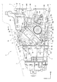
図6において、フロントケース6の右縦壁6Rには複数のケース側ボス部35A、35B、35C、35Dが設けられている。
In FIG. 6, a plurality of case-
ケース側ボス部35Aは、右縦壁6Rの上部においてシフトアンドセレクト軸33の後斜め下方に形成されており、フランジ部6Fに連結されている。ケース側ボス部35Bは、右縦壁6Rの上部においてケース側ボス部35Aと同じ高さ位置で前後方向に並んで形成されており、リブ36Aによってフランジ部6Dに連結されている。
The case-
ケース側ボス部35Cは、右縦壁6Rの下部においてシフトアンドセレクト軸33の真下に形成されており、開口部6Cと前後方向に並んでいる。ケース側ボス部35Dは、右縦壁6Rの下部において開口部6Cの前方に形成されている。ケース側ボス部35Cとケース側ボス部35Dとを結んだ仮想平面Lは、開口部6Cを通っている。すなわち、仮想平面Lは、開口部6Cを前後方向に横切っている。
The case-
ケース側ボス部35Cにはリブ36B、36Cが連結されており、リブ36B、36Cは、ケース側ボス部35Cからそれぞれ前後方向に延びている。後側のリブ36Cは、ケース側ボス部35Cからフランジ部6Fに向かって延びている。
The
ケース側ボス部35Dにはリブ36Dが連結されており、リブ36Dは、ケース側ボス部35Dからフランジ部6Dの下部に位置するボス部6Eまで延び、ボス部6Eに連結されている。
The
右縦壁6Rには開口部6Cよりも上方にリブ36Eが設けられており、リブ36Eは、フランジ部6Dとフランジ部6Fとを連結している。すなわち、リブ36Eは、フランジ部6Dからフランジ部6Fまで延びている。リブ36Eは、開口部6Cの上縁6uと上下方向において隣接している。本実施例のリブ36Dは、本発明のリブを構成する。
The right
右縦壁6Rにはリブ36Fが設けられており、リブ36Fは、上下方向においてシフトアンドセレクト軸33とリブ36Eとの間に設けられている。リブ36Fは、フランジ部6Dとフランジ部6Fとを連結している。すなわち、リブ36Fは、フランジ部6Dからフランジ部6Fまで延びている。
A
右縦壁6Rには開口部6Cよりも下方にリブ36Gが設けられており、リブ36Gは、フランジ部6Dとフランジ部6Fとを連結している。すなわち、リブ36Gは、フランジ部6Dからフランジ部6Fまで延びている。
The right
リブ36E、36F、36Gは、フロントケース6を補強するために設けられており、エンジン3の振動によって変速機ケース4が上下方向、前後方向あるいは入力軸21の軸線周りに変形や振動する場合に、フロントケース6の振動や変形を抑制する。
The
本実施例のケース側ボス部35Cは、本発明の第1のケース側ボス部を構成し、ケース側ボス部35Dは、本発明の第2のケース側ボス部を構成する。フランジ部6Fは、本発明の第2のケース側フランジ部を構成し、フランジ部6Dは、本発明の第3のケース側フランジ部を構成する。リブ36Eは、本発明の補強部を構成する。
The case-
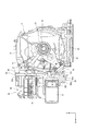
図7において、ベースプレート50は、平板部50Aと平板部50Aから前方に向かって水平に延びる台座部50Bとを有する。平板部50Aには開口部50aが形成されている。開口部50aにはシフトアンドセレクト軸33の操作レバー33Aが挿通され、操作レバー33Aは、開口部50aを通して筐体42の開口部に挿入される。すなわち、操作レバー33Aは、開口部を通して右縦壁6Rから外方に突出している。
In FIG. 7, the
平板部50Aの上部には筐体42が取付けられている。図1において、筐体42は、底部の前端部42aが底部の後端部42bよりも上方に位置するように平板部50Aに取付けられている。
A
平板部50Aの下部にはアキュムレータ取付部50Cが形成されている。アキュムレータ取付部50Cは、平板部50Aから右方に向かって筒状に突出しており(図5参照)、アキュムレータ取付部50Cには円筒状のアキュムレータ47が取付けられている。
An
図1において、アキュムレータ47は、筐体42と上下方向に重なるように設置されている。これにより、ベースプレート50の上下方向の寸法を短くすることができ、フロントケース6の上下方向の寸法を短縮して、変速機ケース4の小型化を図ることができる。
In FIG. 1, the
台座部50Bの上面にはオイルポンプ49が取付けられており、台座部50Bの下面にはモータ48が設置されている。リザーブタンク46は、平板部50Aの上面と台座部50Bの前端に取付けられており、前後方向においてオイルポンプ49を跨がるようにして設置されている。
An
このようにオイルポンプ49およびモータ48を台座部50Bの上下面に取付けることにより、オイルポンプ49およびモータ48を前後方向あるいは左右方向に並んで設置する場合に比べてベースプレート50の前後方向の長さを短縮できる。このため、フロントケース6の前後方向の寸法を短縮して、変速機ケース4のより一層の小型化を図ることができる。
By mounting the
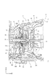
図1、図2において、アキュムレータ取付部50Cの下部には取付片50mが設けられており、取付片50mの下端部には一対のボルト57Aによってブラケット56が締結されている。図2において、ブラケット56にはボス部56a、56bが形成されており、ボス部56a、56bは、傾斜部56Aから右縦壁6Rに向かって突出している。
In FIGS. 1 and 2, a mounting
ハウジング32Aにはボス部56a、56bに対向する位置にボス部32a、32bが形成されている。ハウジング32Aは、ボス部56aとボス部32aおよびボス部56bとボス部32bとが図示しないボルトによって締結されることにより、ブラケット56に固定されている。
The
図7において、ベースプレート50の平板部には複数のプレート側ボス部54A、54B、54C、54Dが設けられている。プレート側ボス部54Aは、ケース側ボス部35Aに締結されており、プレート側ボス部54Bは、ケース側ボス部35Bに締結されている。
In FIG. 7, a plurality of plate-
プレート側ボス部54Cは、ケース側ボス部35Cに締結されており、プレート側ボス部54Dは、ケース側ボス部35Dに締結されている。
The plate-
ケース側ボス部35Cとケース側ボス部35Dとは、開口部6Cを挟んで前後方向に設置されているので、プレート側ボス部54Cとプレート側ボス部54Dとは、開口部6Cを跨いでケース側ボス部35Cとケース側ボス部35Dとに締結されている。したがって、プレート側ボス部54Cおよびプレート側ボス部54Dは、開口部6Cを跨いで右縦壁6Rに締結されている。
Since the case-
プレート側ボス部54Cからアキュムレータ取付部50Cに向かってリブ55Aが延びており、プレート側ボス部54Cとアキュムレータ取付部50Cとは、リブ55Aによって連結されている。プレート側ボス部54Dは、アキュムレータ取付部50Cに連結されている。
The
図6に示すように、ケース側ボス部35Dは、リブ36Dによってフランジ部6Dの下部に位置するボス部6Eに連結されているので、アキュムレータ取付部50Cは、ケース側ボス部35Dに締結されたプレート側ボス部54Dが、リブ36Dによってフランジ部6Dの下部に位置するボス部6Eに連結されている。
As shown in FIG. 6, since the case-
すなわち、本実施例の自動変速機2は、ケース側ボス部35Aとプレート側ボス部54Aとを1組とし、ケース側ボス部35Bとプレート側ボス部54Bとを1組とする。さらに、ケース側ボス部35Cとプレート側ボス部54Cとを1組とし、ケース側ボス部35Dとプレート側ボス部54Dとを1組とした場合には、締結部が4組から構成されている。
That is, in the
この4組の締結部のうち、ケース側ボス部35Dおよびプレート側ボス部54Dがリブ36Dによってフランジ部6Dの下部に位置するボス部6Eに連結されている。
Of these four sets of fastening portions, the case-
図1において、フロントケース6の下部にはオイルパン61が取付けられており、オイルパン61にオイルが貯留されている。図5において、オイルパン61とフロントケース6の下部との間にはバルブボディ62が収容されており、バルブボディ62は、図示しないボルトによってフロントケース6の下部に締結されている。
In FIG. 1, an
バルブボディ62は、オイルポンプ12によってオイルパン61から吸い上げられたオイルを、トルコンハウジング5の隔壁5Aやリヤポンプケース13に形成された図示しない油路を通してトルクコンバータ10に供給する。本実施例のトルクコンバータ10は、オイル供給部を構成する。
The
このように本実施例の自動変速機2によれば、シフトユニット41が、フロントケース6の右縦壁6Rに固定されたベースプレート50と、ベースプレート50に取付けられ、クラッチレバー31を揺動させるクラッチアクチュエータ32とを備えている。フロントケース6は、開口部6Cを有し、クラッチレバー31の外端部31bが開口部6Cからフロントケース6の外部に突出している。
As described above, according to the
さらに、ベースプレート50は、フロントケース6の右縦壁6Rに締結されたプレート側ボス部54Aからプレート側ボス部54Dを有し、プレート側ボス部54C、54Dは、開口部6Cを跨いで右縦壁6Rに締結されている。
Further, the
これにより、フロントケース6にクラッチレバー31を突出させるための開口部6Cが形成されている場合に、ベースプレート50によって開口部6Cの周辺の右縦壁6Rの剛性を容易に向上させることができ、フロントケース6の剛性を容易に向上させることができる。この結果、開口部6Cが振動することや変形することを容易に抑制でき、クラッチレバー31を確実、かつ安定して操作できる。
As a result, when the opening 6C for projecting the
また、本実施例の自動変速機2によれば、開口部6Cよりも下方においてフロントケース6にバルブボディ62が締結されており、バルブボディ62は、トルクコンバータ10にオイルを供給する。
Further, according to the
これにより、剛性の高いバルブボディ62によってフロントケース6の下部の剛性を向上させることができ、エンジン3の振動によってフロントケース6が上下方向、前後方向あるいは入力軸21の軸線周りに変形や振動することを抑制でき、結果的に変速機ケース4が上下方向、前後方向あるいは入力軸21の軸線周りに変形や振動することを抑制できる。
As a result, the rigidity of the lower part of the
これに加えて、開口部6Cよりも下方においてフロントケース6にバルブボディ62が締結されているので、開口部6Cがバルブボディ62に近づくように開口部6Cを右縦壁6Rに形成すれば、ベースプレート50に加えてバルブボディ62によって開口部6Cの周辺の剛性をより一層向上させることができる。このため、開口部6Cが振動することや変形することをより効果的に抑制できる。
In addition to this, since the
また、本実施例の自動変速機2によれば、フロントケース6は、前端部にトルコンハウジング5に締結されたフランジ部6Dを有し、後端部にリヤケース7に締結されたフランジ部6Fを有する。
Further, according to the
フロントケース6の右縦壁6Rにはリブ36Eが形成されており、リブ36Eは、フランジ部6Dとフランジ部6Fとを連結するように入力軸21の軸方向に沿って延び、開口部6Cの上縁6uと上下方向で隣接している。
A
これにより、右縦壁6Rを補強する剛性の高いリブ36Eをフランジ部6Dおよびフランジ部6Fに連結することにより、リブ36Eの剛性をより一層高くできる。このため、リブ36Eによってフロントケース6が振動することや変形することをより効果的に抑制できる。
As a result, the rigidity of the
これに加えて、剛性の高いリブ36Eの真下に開口部6Cを形成できるので、開口部6Cの上縁6uの剛性をリブ36Eによって向上でき、開口部6Cが振動することや変形することをより効果的に抑制できる。
In addition to this, since the opening 6C can be formed directly under the highly
また、本実施例の自動変速機2によれば、フロントケース6の右縦壁6Rに、プレート側ボス部54C、54Dにそれぞれ締結されたケース側ボス部35C、35Dが設けられており、ケース側ボス部35Dおよびプレート側ボス部54Dがリブ36Dによってフランジ部6Dに連結されている。
Further, according to the
これにより、ケース側ボス部35Dおよびプレート側ボス部54Dの剛性をリブ36Dによって高くできる上に、開口部6Cの前側の右縦壁6Rの剛性をリブ36Dによって高くできる。
As a result, the rigidity of the case-
このため、ベースプレート50によって右縦壁6Rの剛性を高くできることに加えて、開口部6Cの前側の右縦壁6Rの剛性をリブ36Dによって高くできることにより、開口部6Cの周辺の剛性をより一層向上できる。この結果、開口部6Cが振動することや変形することをより効果的に抑制できる。
Therefore, in addition to being able to increase the rigidity of the right
また、アキュムレータ取付部50Cがプレート側ボス部54Dに連結されており、ケース側ボス部35Dに締結されたプレート側ボス部54Dがリブ36Dによってフランジ部6Dの下部に位置するボス部6Eに連結されている。
Further, the
これにより、アキュムレータ取付部50Cの剛性を高くでき、高圧のオイルを蓄圧するアキュムレータ47の作動時の振動をリブ36Dから剛性の高いフランジ部6Dに逃がすことができる。
As a result, the rigidity of the
このため、アキュムレータ47の作動時の振動によって開口部6Cの周辺が振動することや変形することを抑制でき、結果的に開口部6Cが振動することや変形することをより効果的に抑制できる。
Therefore, it is possible to suppress the vibration and deformation of the periphery of the opening 6C due to the vibration during operation of the
なお、本実施例の自動変速機2において、ケース側ボス部35Cをリブによってフランジ部6Fに連結してもよい。
In the
また、本実施例の自動変速機2によれば、右縦壁6Rにケース側ボス部35Cと、開口部6Cを挟んでケース側ボス部35Cに対向するケース側ボス部35Dとを有し、ケース側ボス部35Cとケース側ボス部35Dとを結んだ仮想平面Lが、開口部6Cを前後方向に横切っている。
Further, according to the
これにより、プレート側ボス部54C、54Dを、開口部6Cを跨いでケース側ボス部35C、35Dに締結させることができる。このため、ベースプレート50によって開口部6Cの周辺の右縦壁6Rの剛性をより効果的に高めることができる。
As a result, the plate-
なお、本実施例の自動変速機2は、ケース側ボス部35Cとケース側ボス部35Dとを結んだ仮想平面Lが開口部6Cを前後方向に横切るように、右縦壁6Rにケース側ボス部35C、35Dを設けているが、これに限定されるものではない。
In the
例えば、ケース側ボス部35Cとケース側ボス部35Dとを結んだ仮想平面Lが開口部6Cを上下方向に横切るように、右縦壁6Rにケース側ボス部35C、35Dを設けてもよい。
For example, the case-
また、本実施例のクラッチアクチュエータは、油圧によって操作されるクラッチアクチュエータ32が用いられているが、モータ等の電気式のクラッチアクチュエータや電磁ソレノイド等の電磁式のクラッチアクチュエータから構成されてもよく、これらに限定されるものでもない。また、本実施例の自動変速機2は、AMTに限定されるものではなく、AT(Automatic Transmission)から構成されてもよい。
Further, although the
本発明の実施例を開示したが、当業者によっては本発明の範囲を逸脱することなく変更が加えられうることは明白である。すべてのこのような修正および等価物が次の請求項に含まれることが意図されている。 Although embodiments of the present invention have been disclosed, it will be apparent to those skilled in the art that modifications may be made without departing from the scope of the invention. All such modifications and equivalents are intended to be included in the following claims.
2...自動変速機、3...エンジン(内燃機関)、4...変速機ケース、5...トルコンハウジング(第3のケース)、6...フロントケース(第1のケース)、6C...開口部(第1のケースの開口部)、6D...(第3のケース側フランジ部)、6F...フランジ部(第2のケース側フランジ部)、6R...右縦壁(第1のケースの外壁)、6u...上縁(開口部の上縁)、7...リヤケース(第2のケース)、21...入力軸、21a...前端部(入力軸の軸方向端部)、31...クラッチレバー、31b...外端部(クラッチレバーの径方向の外端部)、32...クラッチアクチュエータ、35C...ケース側ボス部(第1のケース側ボス部)、35D...ケース側ボス部(第2のケース側ボス部)、36D...リブ、36E...リブ(補強部)、41...シフトユニット、50...ベースプレート、54C,54D...プレート側ボス部、62...バルブボディ 2 ... automatic transmission, 3 ... engine (internal combustion engine), 4 ... transmission case, 5 ... torque converter housing (third case), 6 ... front case (first case) ), 6C ... opening (opening of the first case), 6D ... (third case side flange part), 6F ... flange part (second case side flange part), 6R. .. Right vertical wall (outer wall of first case), 6u ... upper edge (upper edge of opening), 7 ... rear case (second case), 21 ... input shaft, 21a .. Front end (axial end of input shaft), 31 ... clutch lever, 31b ... outer end (radial outer end of clutch lever), 32 ... clutch actuator, 35C ... Case side boss part (first case side boss part), 35D ... Case side boss part (second case side boss part), 36D ... rib, 36E ... rib (reinforcing part), 41. .. shift unit, 50 ... base plate, 54C, 54D ... plate side boss, 62 ... valve body
Claims (5)
前記第1のケース内において前記入力軸の軸方向端部に設けられ、内燃機関と前記入力軸との間で動力を伝達可能または動力を遮断可能なクラッチと、
前記入力軸から径方向外方に延び、その径方向の外端部に作用する操作力によって揺動することにより、前記クラッチを切断するクラッチレバーと、
前記第1のケースの外壁に取付けられたシフトユニットとを有し、
前記シフトユニットが、前記外壁に固定されたベースプレートと、前記ベースプレートに取付けられ、前記クラッチレバーを揺動させるクラッチアクチュエータとを含んで構成される自動変速機であって、
前記第1のケースは、開口部を有し、前記クラッチレバーの前記外端部は、前記開口部から前記第1のケースの外部に突出しており、
前記ベースプレートは、前記第1のケースの外壁に締結された複数のプレート側ボス部を有し、前記プレート側ボス部は、前記開口部を跨いで前記外壁に締結されていることを特徴とする自動変速機。 A transmission case having a first case and a second case connected to each other and rotatably supporting an input shaft inside the first case and the second case.
A clutch provided at the axial end of the input shaft in the first case and capable of transmitting or disconnecting power between the internal combustion engine and the input shaft.
A clutch lever that disengages the clutch by extending outward in the radial direction from the input shaft and swinging due to an operating force acting on the outer end portion in the radial direction.
It has a shift unit mounted on the outer wall of the first case.
An automatic transmission in which the shift unit includes a base plate fixed to the outer wall and a clutch actuator attached to the base plate to swing the clutch lever.
The first case has an opening, and the outer end portion of the clutch lever projects from the opening to the outside of the first case.
The base plate has a plurality of plate-side boss portions fastened to the outer wall of the first case, and the plate-side boss portions are fastened to the outer wall across the opening. Automatic transmission.
前記第1のケースの外壁に補強部が形成され、前記補強部は、前記第2のケース側フランジ部と前記第3のケース側フランジ部とを連結するように前記入力軸の軸方向に沿って延び、前記開口部の上縁と上下方向で隣接していることを特徴とする請求項1または請求項2に記載の自動変速機。 The first case has a second case-side flange portion fastened to the second case at one end in the axial direction of the input shaft, and a third portion at the other end in the axial direction of the input shaft. Has a third case-side flange fastened to the case of
A reinforcing portion is formed on the outer wall of the first case, and the reinforcing portion is along the axial direction of the input shaft so as to connect the second case-side flange portion and the third case-side flange portion. The automatic transmission according to claim 1 or 2, wherein the automatic transmission extends vertically and is adjacent to the upper edge of the opening in the vertical direction.
前記複数のケース側ボス部と前記複数のケース側ボス部の1組以上は、リブによって前記第2のケース側フランジ部または前記第3のケース側フランジ部に連結されていることを特徴とする請求項3に記載の自動変速機。 A plurality of case-side boss portions fastened to the plurality of plate-side boss portions are provided on the outer wall of the first case.
One or more sets of the plurality of case-side boss portions and the plurality of case-side boss portions are connected to the second case-side flange portion or the third case-side flange portion by ribs. The automatic transmission according to claim 3.
Priority Applications (4)
| Application Number | Priority Date | Filing Date | Title |
|---|---|---|---|
| JP2018079789A JP6984530B2 (en) | 2018-04-18 | 2018-04-18 | Automatic transmission |
| DE102019205212.6A DE102019205212B4 (en) | 2018-04-18 | 2019-04-11 | automatic transmission |
| CN201910303900.6A CN110397720B (en) | 2018-04-18 | 2019-04-16 | Automatic transmission |
| FR1904101A FR3080333B1 (en) | 2018-04-18 | 2019-04-17 | AUTOMATIC TRANSMISSION |
Applications Claiming Priority (1)
| Application Number | Priority Date | Filing Date | Title |
|---|---|---|---|
| JP2018079789A JP6984530B2 (en) | 2018-04-18 | 2018-04-18 | Automatic transmission |
Publications (2)
| Publication Number | Publication Date |
|---|---|
| JP2019190475A JP2019190475A (en) | 2019-10-31 |
| JP6984530B2 true JP6984530B2 (en) | 2021-12-22 |
Family
ID=68105412
Family Applications (1)
| Application Number | Title | Priority Date | Filing Date |
|---|---|---|---|
| JP2018079789A Active JP6984530B2 (en) | 2018-04-18 | 2018-04-18 | Automatic transmission |
Country Status (4)
| Country | Link |
|---|---|
| JP (1) | JP6984530B2 (en) |
| CN (1) | CN110397720B (en) |
| DE (1) | DE102019205212B4 (en) |
| FR (1) | FR3080333B1 (en) |
Families Citing this family (1)
| Publication number | Priority date | Publication date | Assignee | Title |
|---|---|---|---|---|
| JP7501137B2 (en) | 2020-06-16 | 2024-06-18 | スズキ株式会社 | Vehicle power transmission device |
Family Cites Families (12)
| Publication number | Priority date | Publication date | Assignee | Title |
|---|---|---|---|---|
| JPS6245109A (en) | 1985-08-23 | 1987-02-27 | Hitachi Ltd | heat treatment equipment |
| DE102007021775A1 (en) * | 2007-05-10 | 2008-11-13 | Daimler Ag | Motor vehicle, has clutch bell-housing coupled with engine control housing as part of flange connection, and separate bridge element fastened to fastening position of clutch bell-housing and fastening position of base body |
| US9032841B2 (en) * | 2012-04-30 | 2015-05-19 | Caterpillar Inc. | Transmission housing having integrally-formed walls |
| GB201210626D0 (en) * | 2012-06-15 | 2012-08-01 | Agco Int Gmbh | Pump installations |
| WO2015072995A1 (en) * | 2013-11-14 | 2015-05-21 | Volvo Truck Corporation | Compound transmission configured for in vehicle range transmission service |
| JP6299518B2 (en) * | 2014-08-11 | 2018-03-28 | スズキ株式会社 | Automatic transmission for vehicles |
| JP6357963B2 (en) * | 2014-08-11 | 2018-07-18 | スズキ株式会社 | Automatic transmission for vehicles |
| JP6245109B2 (en) * | 2014-08-11 | 2017-12-13 | スズキ株式会社 | Automatic transmission |
| JP6460593B2 (en) * | 2014-09-26 | 2019-01-30 | 愛知機械工業株式会社 | Transmission case and transmission including the same |
| JP6331993B2 (en) * | 2014-11-27 | 2018-05-30 | スズキ株式会社 | Automatic transmission |
| CN206175629U (en) * | 2016-08-31 | 2017-05-17 | 南昌江铃集团协和传动技术有限公司 | Indulge electronic new energy automobile gearbox of formula of putting |
| JP6376268B2 (en) * | 2017-11-07 | 2018-08-22 | スズキ株式会社 | Automatic transmission |
-
2018
- 2018-04-18 JP JP2018079789A patent/JP6984530B2/en active Active
-
2019
- 2019-04-11 DE DE102019205212.6A patent/DE102019205212B4/en active Active
- 2019-04-16 CN CN201910303900.6A patent/CN110397720B/en active Active
- 2019-04-17 FR FR1904101A patent/FR3080333B1/en active Active
Also Published As
| Publication number | Publication date |
|---|---|
| CN110397720B (en) | 2022-08-26 |
| JP2019190475A (en) | 2019-10-31 |
| DE102019205212B4 (en) | 2022-05-25 |
| CN110397720A (en) | 2019-11-01 |
| DE102019205212A1 (en) | 2019-10-24 |
| FR3080333B1 (en) | 2022-08-12 |
| FR3080333A1 (en) | 2019-10-25 |
Similar Documents
| Publication | Publication Date | Title |
|---|---|---|
| JP6245109B2 (en) | Automatic transmission | |
| JP6331993B2 (en) | Automatic transmission | |
| JP6357963B2 (en) | Automatic transmission for vehicles | |
| JP6376268B2 (en) | Automatic transmission | |
| JP6984530B2 (en) | Automatic transmission | |
| JP2018105476A (en) | Automatic transmission | |
| JP6299518B2 (en) | Automatic transmission for vehicles | |
| JP7087621B2 (en) | Automatic transmission | |
| JP6958469B2 (en) | Automatic transmission | |
| JP7035757B2 (en) | Automatic transmission | |
| JP2016038068A (en) | Vehicle transmission | |
| JP6992664B2 (en) | Automatic transmission | |
| JP7006478B2 (en) | Automatic transmission | |
| JP7006479B2 (en) | Rotating shaft support structure | |
| JP7433578B2 (en) | Vehicle transmission | |
| JP7091884B2 (en) | Automatic transmission | |
| JP7024572B2 (en) | Vehicle transmission | |
| JP2020003035A (en) | Vehicular transmission | |
| JP6443526B2 (en) | Automatic transmission for vehicles | |
| JP6384584B2 (en) | Automatic transmission for vehicles | |
| JP2020003036A (en) | Automatic transmission | |
| JP6635179B2 (en) | Automatic transmission for vehicles | |
| JP2011105196A (en) | Driving device for hybrid vehicle | |
| JP2021196018A (en) | Vehicle power transmission device |
Legal Events
| Date | Code | Title | Description |
|---|---|---|---|
| A621 | Written request for application examination |
Free format text: JAPANESE INTERMEDIATE CODE: A621 Effective date: 20210121 |
|
| TRDD | Decision of grant or rejection written | ||
| A977 | Report on retrieval |
Free format text: JAPANESE INTERMEDIATE CODE: A971007 Effective date: 20211014 |
|
| A01 | Written decision to grant a patent or to grant a registration (utility model) |
Free format text: JAPANESE INTERMEDIATE CODE: A01 Effective date: 20211026 |
|
| A61 | First payment of annual fees (during grant procedure) |
Free format text: JAPANESE INTERMEDIATE CODE: A61 Effective date: 20211108 |
|
| R151 | Written notification of patent or utility model registration |
Ref document number: 6984530 Country of ref document: JP Free format text: JAPANESE INTERMEDIATE CODE: R151 |