JP6981069B2 - Relays, programs, and network systems - Google Patents
Relays, programs, and network systems Download PDFInfo
- Publication number
- JP6981069B2 JP6981069B2 JP2017139164A JP2017139164A JP6981069B2 JP 6981069 B2 JP6981069 B2 JP 6981069B2 JP 2017139164 A JP2017139164 A JP 2017139164A JP 2017139164 A JP2017139164 A JP 2017139164A JP 6981069 B2 JP6981069 B2 JP 6981069B2
- Authority
- JP
- Japan
- Prior art keywords
- server
- image processing
- job
- processing device
- mfp
- Prior art date
- Legal status (The legal status is an assumption and is not a legal conclusion. Google has not performed a legal analysis and makes no representation as to the accuracy of the status listed.)
- Active
Links
- 238000012545 processing Methods 0.000 claims description 89
- 230000005540 biological transmission Effects 0.000 claims description 57
- 238000004891 communication Methods 0.000 claims description 43
- 230000004044 response Effects 0.000 description 13
- 238000010586 diagram Methods 0.000 description 8
- 238000000034 method Methods 0.000 description 8
- 230000008569 process Effects 0.000 description 7
- 230000001960 triggered effect Effects 0.000 description 4
- 238000012986 modification Methods 0.000 description 2
- 230000004048 modification Effects 0.000 description 2
- 230000005856 abnormality Effects 0.000 description 1
- 230000008859 change Effects 0.000 description 1
- 230000003111 delayed effect Effects 0.000 description 1
- 239000004973 liquid crystal related substance Substances 0.000 description 1
- 238000005259 measurement Methods 0.000 description 1
- 230000009467 reduction Effects 0.000 description 1
- 238000012546 transfer Methods 0.000 description 1
Images


Landscapes
- Accessory Devices And Overall Control Thereof (AREA)
- Facsimiles In General (AREA)
- Facsimile Transmission Control (AREA)
Description
本開示は、中継装置、プログラム、および、ネットワークシステムに関し、特に、クラウドサーバーとクライアントとの間でジョブを中継する中継装置、そのような中継装置によって実行されるプログラム、および、そのような中継装置を含むネットワークシステムに関する。 The present disclosure relates to relay devices, programs, and network systems, in particular, relay devices that relay jobs between a cloud server and a client, programs executed by such relay devices, and such relay devices. Regarding network systems including.
従来、ネットワーク内のクライアント装置が中継装置を介して外部のサーバーと通信するための技術が種々提供されている。たとえば、特開2014−175747号公報(特許文献1)は、自律分散型ネットワークシステムを開示している。当該ネットワークシステムでは、図5等に記載されるように、通信不能となった第2中継装置5の第2中継装置ネットワーク12に所属するノードn6が、第1中継装置4の第1中継装置ネットワーク11に所属するノードn3から異常情報を含む中継装置情報を受け取る。そして、ノードn6は、第1中継装置ネットワーク11に所属するノードに対して、自立して第1中継装置ネットワーク11への参入を要求し、第2中継装置ネットワーク12から、第1中継装置ネットワーク11に参入する(「要約書」参照)。 Conventionally, various techniques for a client device in a network to communicate with an external server via a relay device have been provided. For example, Japanese Patent Application Laid-Open No. 2014-175747 (Patent Document 1) discloses an autonomous decentralized network system. In the network system, as shown in FIG. 5 and the like, the node n6 belonging to the second relay device network 12 of the second relay device 5 that has become unable to communicate is the first relay device network of the first relay device 4. Receives relay device information including abnormality information from the node n3 belonging to 11. Then, the node n6 independently requests the node belonging to the first relay device network 11 to enter the first relay device network 11, and the second relay device network 12 to the first relay device network 11 (See "Summary").
しかしながら、従来のネットワークシステムでは、中継装置が交代する際、ネットワーク内のクライアント装置が一時的にサーバーと通信できなくなる、いわゆるダウンタイムが発生していた。このことから、ダウンタイムの発生を回避できるようなネットワークシステムが求められている。 However, in the conventional network system, when the relay device is replaced, so-called downtime occurs in which the client device in the network temporarily cannot communicate with the server. For this reason, there is a demand for a network system that can avoid the occurrence of downtime.
本開示は、係る実情に鑑み考え出されたものであり、その目的は、ネットワークシステムにおいてダウンタイムの発生を回避することである。 The present disclosure has been devised in view of such circumstances, the purpose of which is to avoid the occurrence of downtime in network systems.
本開示のある局面に従うと、所定のネットワーク内の画像処理装置、および、所定のネットワーク外のサーバーと通信可能な通信インターフェースと、プロセッサーとを備えた中継装置であって、プロセッサーは、画像処理装置とサーバーとの間のデータの送受信が発生しないときに、画像処理装置およびサーバーに、所定のネットワークのゲートウェイとして中継装置を指定することを通知するように構成されている、中継装置が提供される。 According to certain aspects of the present disclosure, a relay device comprising an image processing device in a predetermined network, a communication interface capable of communicating with a server outside the predetermined network, and a processor, wherein the processor is an image processing device. A relay device is provided that is configured to notify the image processor and server that it is designated as a gateway for a given network when no data is sent or received between the server and the server. ..
画像処理装置とサーバーとの間のデータの送受信が発生していないときは、画像処理装置がサーバーへジョブのデータを送信していないときを含んでもよい。 When the data is not transmitted or received between the image processing device and the server, it may include the case where the image processing device is not transmitting the job data to the server.
画像処理装置がサーバーへジョブのデータを送信していないときは、当該画像処理装置がファックス受信連携ジョブを実行中であるときに、当該画像処理装置がファックス受信連携ジョブに係るデータをサーバーに向けて送信するまでの期間を含んでもよい。 When the image processing device does not send the job data to the server, when the image processing device is executing the fax reception cooperation job, the image processing device directs the data related to the fax reception cooperation job to the server. It may include the period until it is transmitted.
画像処理装置がサーバーへジョブのデータを送信していないときは、当該画像処理装置がスキャンされた文書のサーバーへの送信を含むジョブを実行中であるときに、当該画像処理装置がスキャンされた文書をサーバーに向けて送信するまでの期間を含んでもよい。 When the image processor is not sending job data to the server, the image processor was scanned while the image processor was running a job that included sending the scanned document to the server. It may include the period until the document is sent to the server.
画像処理装置とサーバーとの間のデータの送受信が発生していないときは、サーバーが所定のネットワークにおいて中継装置として動作している他の装置を介して画像処理装置にジョブのデータを送信していないときを含んでもよい。 When data is not being sent or received between the image processing device and the server, the job data is being sent to the image processing device via another device in which the server is operating as a relay device in a given network. It may include when there is no such thing.
プロセッサーは、要求をサーバーに送信した後、要求を送信した画像処理装置に所定のネットワークのゲートウェイとして中継装置を指定することを通知するように構成されていてもよい。 The processor may be configured to send the request to the server and then notify the image processor that sent the request to designate the relay device as a gateway for a given network.
画像処理装置と一体的に構成されていてもよい。
本開示の他の局面に従うと、所定のネットワーク内の画像処理装置、および、所定のネットワーク外のサーバーと通信可能な通信インターフェースを備えたコンピューターによって実行されるプログラムが提供される。プログラムは、画像処理装置とサーバーとの間のデータの送受信が発生しているか否かを判断するステップと、画像処理装置とサーバーとの間のデータの送受信が発生していない場合に、画像処理装置およびサーバーに、所定のネットワークのゲートウェイとしてコンピューターを指定することを通知するステップと、サーバーに所定のネットワークのゲートウェイとしてコンピューターを指定することを通知した後、画像処理装置が所定のネットワークにおいて中継装置として動作している他の装置を介してサーバーにジョブ送信の要求を送信した場合に、当該要求をサーバーに送信するステップとを実行させる。
It may be integrally configured with the image processing device.
According to other aspects of the disclosure, there is provided a program executed by an image processing device within a predetermined network and a computer having a communication interface capable of communicating with a server outside the predetermined network. If the program is, the transmission and reception of data between the steps of transmitting and receiving data between the image processing apparatus and the server determines whether the occurred, the image processing apparatus and the server does not occur, the image processing After notifying the device and server that the computer is designated as the gateway for the given network and notifying the server that the computer is designated as the gateway for the given network, the image processing device relays the device in the given network. When a request for job transmission is sent to the server via another device operating as a device, the step of sending the request to the server is executed.
本開示のさらに他の局面に従うと、所定のネットワーク内の画像処理装置と、所定のネットワーク外のサーバーと、画像処理装置とサーバーとの間を中継するための第1の中継装置および第2の中継装置とを備え、第2の中継装置は、所定のネットワーク内の1台以上の画像処理装置、および、所定のネットワーク外のサーバーと通信可能な通信インターフェースと、プロセッサーとを含み、プロセッサーは、画像処理装置とサーバーとの間のデータの送受信が発生しない場合に、画像処理装置およびサーバーに、所定のネットワークのゲートウェイとして第2の中継装置を指定することを通知し、サーバーに所定のネットワークのゲートウェイとして第2の中継装置を指定することを通知した後、画像処理装置が所定のネットワークにおいて中継装置として動作している第1の中継装置を介してサーバーにジョブ送信の要求を送信した場合に、当該要求をサーバーに送信する、ように構成されている、ネットワークシステムが提供される。 According to still another aspect of the present disclosure, a first relay device and a second relay device for relaying between an image processing device in a predetermined network, a server outside the predetermined network, and the image processing device and the server. The second relay device comprises a relay device, the second relay device includes one or more image processing devices in a predetermined network, a communication interface capable of communicating with a server outside the predetermined network, and a processor. When data is not sent or received between the image processing device and the server, the image processing device and the server are notified that the second relay device is designated as the gateway of the predetermined network, and the server is notified of the predetermined network. When the image processing device sends a job transmission request to the server via the first relay device operating as a relay device in a predetermined network after notifying that the second relay device is designated as the gateway. A network system is provided that is configured to send the request to the server.
本開示によれば、中継装置は、サーバーと所定のネットワーク内の画像処理装置との間のデータの送受信が発生していないときに、サーバーと画像処理装置に所定のネットワーク内の中継装置の切替を指示する。これにより、所定のネットワーク内の中継装置の切替の際にダウンタイムは発生しない。 According to the present disclosure, the relay device switches the relay device in the predetermined network to the server and the image processing device when data transmission / reception between the server and the image processing device in the predetermined network does not occur. To instruct. As a result, no downtime occurs when switching the relay device in the predetermined network.
以下に、図面を参照しつつ、本開示に係るネットワークシステムの実施の形態について説明する。以下の説明では、同一の部品および構成要素には同一の符号を付してある。それらの名称および機能も同じである。したがって、これらの説明は繰り返さない。 Hereinafter, embodiments of the network system according to the present disclosure will be described with reference to the drawings. In the following description, the same parts and components are designated by the same reference numerals. Their names and functions are the same. Therefore, these explanations will not be repeated.
[1.ネットワークシステムの構成の概要]
図1は、ネットワークシステムの構成の一例を模式的に示す図である。図1に示されるように、チャットシステムは、ローカルエリアネットワーク(LAN)200と、クラウドネットワーク300とを含む。
[1. Overview of network system configuration]
FIG. 1 is a diagram schematically showing an example of a network system configuration. As shown in FIG. 1, the chat system includes a local area network (LAN) 200 and a
LAN200は、5台のMFP100A〜100Eを含む。クラウドネットワーク300は、クラウドサーバー400とクライアント500とを含む。クライアント500は、たとえばクラウドネットワーク300におけるユーザーによって操作されるパーソナルコンピューターである。
The LAN 200 includes five
LAN200において、5台のMFP100A〜100EのうちMFP100Aがゲートウェイ(GW)として機能している。GWは、クラウドサーバー400との間で、いわゆる「トンネル」(図1中のトンネルTN)と呼ばれる仮想的な通信パスを確立させる。クラウドサーバー400は、トンネルTNを介して、MFP100A〜100Eのそれぞれへジョブ送信の要求およびジョブデータを送信する。また、MFP100A〜100Eのそれぞれは、トンネルTNを介して、クラウドサーバー400へジョブ送信の要求およびジョブデータを送信する。これにより、MFP100A〜100Eを利用したクラウドサービスが提供される。
In LAN200, the MFP100A out of the five
MFP100A〜100Eのそれぞれの構成は等価であってもよい。したがって、以下の説明では、MFP100A〜100Eに共通する構成が「MFP100」として称される。
The respective configurations of the
[2.仮想的なトンネルを利用した通信]
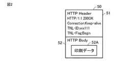
図2は、GWとクラウドサーバー400との間のトンネルを利用したジョブデータの送受信に係るデータの一例を模式的に示す図である。図2に示されたHTTP(Hypertext Transfer Protocol)リクエスト50は、クラウドサーバー400からGWへ送信されるデータの一例であって、クライアント500からの印刷要求に従った印刷用のHTTPリクエストを表わす。HTTPリクエスト50は、ヘッダー51とボディ52とを含む。ヘッダー51は、プロトコル標準ヘッダーと、中継装置としてのMFP100に利用されるトンネル通信用ヘッダーとを含む。ボディ52は印刷データ52Aを含む。
[2. Communication using a virtual tunnel]
FIG. 2 is a diagram schematically showing an example of data related to transmission / reception of job data using a tunnel between the GW and the
GW(中継装置としてのMFP100)は、HTTPリクエスト50を受けると、当該HTTPリクエスト50から印刷データ52Aを取り出し、取り出した印刷データ52Aを当該印刷データ52Aに係る印刷ジョブを実行するMFP100に送信する。
Upon receiving the
[3.LANにおけるゲートウェイの切替]
図3は、図1のネットワークシステムにおけるGWとして機能するMFPが、MFP100AからMFP100Bへと切り替えられた状態を示す図である。図3に示されるようにGWとして動作するMFPがMFP100AからMFP100Bへと切り替えられると、MFP100Bは、クラウドサーバー400との間で仮想的なトンネルを確立させて、クラウドサーバー400とMFP100との間のジョブ送信の要求およびジョブデータの、送受信を中継する。
[3. Switching gateways on LAN]
FIG. 3 is a diagram showing a state in which the MFP functioning as the GW in the network system of FIG. 1 is switched from the
すなわち、クラウドサーバー400は、MFP100Bを介して、MFP100にジョブ送信の要求およびジョブデータを送信する。各MFP100は、MFP100Bを介して、クラウドサーバー400にジョブ送信の要求およびジョブデータを送信する。
That is, the
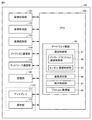
[4.MFP100のハードウェア構成]
図4は、MFP100のハードウェア構成を概略的に示す図である。図3を参照して、MFP100は、全体を制御するためのCPU(Central Processing Unit)150、プログラムおよびデータを格納するための記憶部160、操作パネル170を含む。
[4. Hardware configuration of MFP100]
FIG. 4 is a diagram schematically showing a hardware configuration of the
記憶部160は、CPU150により実行されるプログラムおよび各種データを記憶する。操作パネル170は、ディスプレイ171と、操作部172とを含む。ディスプレイ171の一例は、液晶表示装置である。ディスプレイ171の他の例は、プラズマディスプレイである。操作部172は、MFP100に対する操作の入力を受け付ける。
The
MFP100は、さらに、画像処理部151と、画像形成部152と、画像読取部153と、ファクシミリ通信部154と、ネットワーク通信部155とを含む。画像処理部151は、入力された画像に対して拡大・縮小を含む各種の処理を施す。画像形成部152は、感光体等の、記録用紙に画像を形成するための要素を含む。画像読取部153は、スキャナー等の原稿の画像データを生成するための要素を含み、原稿のスキャンによりスキャンデータを生成する。ファクシミリ通信部154は、モデム等のファクシミリ通信により画像データの送受信するための要素を含む。ネットワーク通信部155は、ネットワークカード等の、ネットワークを介してデータ通信をするための要素を含む。画像処理部151、画像形成部152、画像読取部153、ファクシミリ通信部154、および、ネットワーク通信部155のそれぞれの機能は、画像形成装置においてよく知られたものであるから、ここでは詳細な説明は繰返さない。
The
[5.GWとしての機能構成]
図4において「ゲートウェイ機能40」として示されるように、MFP100のCPU150は、たとえば所定のプログラムを実行することによって、GWとして機能する。ゲートウェイ機能40は、機能的な構成として、通信制御部41、速度測定部45、動作制御部47、および、プロトコル取得部49を含む。
[5. Function configuration as GW]
As shown as "
通信制御部41は、ネットワーク通信部155および/またはファクシミリ通信部154を用いて、他の装置との通信を制御する処理部である。通信制御部41は、メッセージセッション通信制御部42とトンネル通信制御部43とを有する。
The
メッセージセッション通信制御部42は、クラウドネットワーク300内の管理サーバーとの通信をメッセージセッションを用いて実行する処理部である。メッセージセッション通信制御部42は、管理サーバーとの間にメッセージセッションを確立して、管理サーバーとの通信を実行する。
The message session
トンネル通信制御部43は、ネットワーク通信部155を用いて、GWとクラウドサーバー400との間にトンネル接続を確立して、クラウドサーバー400と特定のデバイス(たとえば、MFP100A〜100Eのいずれか)との通信を中継する。
The tunnel
速度測定部45は、ネットワーク通信部155および/またはファクシミリ通信部154を用いて、データの送信経路の通信速度を表わす値を測定する処理部である。動作制御部47は、GWおよびLAN200内の装置のそれぞれの動作モードを制御する処理部である。動作制御部47は、たとえばMFP100A〜100EにGWとして動作するMFP100を特定する情報を送信し、当該MFP100をGWとして登録することを指示する。プロトコル取得部49は、クライアント500および/またはクラウドサーバー400がデータ送信に利用するプロトコルを取得する。
The
[6.ジョブ送信の要求の送信とジョブデータの送信]
本開示に係るネットワークシステムでは、ジョブ送信の要求により、クラウドサーバー400とMFP100との間でセッションが確立され、その後、当該セッションを介してジョブデータが送受信される。
[6. Send job submission request and send job data]
In the network system according to the present disclosure, a session is established between the
一例では、MFP100Cがスマートスキャンジョブを実行する場合、MFP100Cはクラウドサーバー400にスマートスキャンジョブに係るジョブ送信の要求を送信する。これにより、MFP100Cとクラウドサーバー400との間でセッションが確立される。その後、MFP100Cは、当該セッションを介して、スマートスキャンジョブに係るスキャンデータをジョブデータとしてクラウドサーバー400へ送信する。
In one example, when the
他の例では、クラウドサーバー400がMFP100Dを利用したリモートプリントジョブを実行する場合、クラウドサーバー400はMFP100Dにリモートプリントジョブに係るジョブ送信の要求を送信する。これにより、クラウドサーバー400とMFP100Dとの間でセッションが確立される。その後、クラウドサーバー400は、当該セッションを介して、MFP100Dに印刷対象の文書をジョブデータとして送信する。
In another example, when the
ジョブが完了すると、セッションは切断される。
[7.ジョブの種類]
本開示に係るネットワークシステムにおいてMFP100が実行するジョブについて、具体例を以下に示す。
When the job is complete, the session will be disconnected.
[7. Job type]
Specific examples of the jobs executed by the
A.デバイストリガーのジョブ
デバイストリガーのジョブは、ユーザーがMFP100またはクライアント500を操作することによって開始される種類のジョブであり、たとえば、「スマートスキャン」「プルプリント」「ファックス受信連携ジョブ」と呼ばれるジョブを含む。各ジョブを以下に説明する。
A. Device-triggered job A device-triggered job is a type of job that is started by the user operating the MFP100 or
・スマートスキャンジョブ
スマートスキャンジョブは、MFP100におけるスキャンによって生成された画像データをクラウドサーバー400を介して所定の記憶装置に格納するジョブであり、たとえば次の(1)〜(3)の工程を含む。
-Smart scan job The smart scan job is a job for storing image data generated by scanning in the
(1)ユーザーが任意のタイミングでMFP100の操作パネル170を操作することにより、MFP100は、当該MFP100にインストールされているスマートスキャン用のアプリケーションを起動する。
(1) When the user operates the
(2)起動されたアプリケーションは、GW経由で、クラウドサーバー400と通信し、操作パネル170上に表示する情報を得る。
(2) The launched application communicates with the
(3)起動されたアプリケーションは、GW経由で、MFP100におけるスキャンによって生成された画像データを、クラウドサーバー400へ送信する。
(3) The started application transmits the image data generated by the scan in the
・プルプリントジョブ
プルプリントジョブは、MFP100に対する操作に応じて、クラウドネットワーク300上の文書を印刷するジョブであり、たとえば次の(1)〜(3)の工程を含む。
-Pull print job The pull print job is a job for printing a document on the
(1)ユーザーが任意のタイミングでMFP100を操作したことに応じて、MFP100は、GW経由でクラウドサーバー400と接続し、当該操作によって指定された文書を要求する。
(1) In response to the user operating the
(2)クラウドサーバー400は、GW経由で、要求された文書をMFP100へ送信する。
(2) The
(3)MFP100は、GW経由で受信した文書を印刷する。
・ファックス受信連携ジョブ
ファックス受信連携ジョブは、MFP100が受信したファクシミリ文書(データ)をクラウドサーバー400へ送信するジョブであり、たとえば次の(1)〜(4)の工程を含む。
(3) The
-Fax reception cooperation job The fax reception cooperation job is a job of transmitting a facsimile document (data) received by the
(1)MFP100は、任意のタイミングでファクシミリ通信用の回線のコールを受信する。
(1) The
(2)MFP100は、ファクシミリ通信を確立させる。
(3)MFP100は、ファクシミリ通信を介してファクシミリ文書を受信する。
(2) The
(3) The
(4)MFP100は、受信したファクシミリ文書をGW経由でクラウドサーバー400へ送信する。なお、MFP100は、ファクシミリ文書の受信完了後に、クラウドサーバー400へのファクシミリ文書の送信を開始する。
(4) The
B.アプリトリガーのジョブ
アプリトリガーのジョブは、ユーザーが任意のタイミングでクラウドネットワーク300からMFP100に対して文書の印刷等を要求するジョブであり、たとえば、「リモートプリント」「リモートファックス」と呼ばれるジョブを含む。各ジョブを以下に説明する。
B. App-triggered job The app-triggered job is a job in which the user requests the MFP100 to print a document or the like from the
・リモートプリントジョブ
リモートプリントジョブは、ユーザーがクライアント500を操作することにより、MFP100に文書の印刷を指示するジョブであり、たとえば次の(1)〜(3)の工程を含む。
-Remote print job The remote print job is a job instructing the
(1)ユーザーからの操作に応じて、クライアント500がクラウドサーバー400に文書の印刷を要求する。当該要求は、文書を印刷するMFP100の指定を含んでいてもよい。
(1) The
(2)クラウドサーバー400がGW経由でMFP100に上記文書を送信するとともに、当該文書の印刷を指示する。
(2) The
(3)MFP100が受信した文書を印刷する。
なお、MFP100は印刷対象の文書を格納していてもよい。この場合、クラウドサーバー400からMFP100への文書の送信は省略されてもよい。
(3) The document received by the
The
・リモートファックスジョブ
リモートファックスジョブは、ユーザーが指定した文書をMFP100にファクシミリ送信させるジョブであり、たとえば次の(1)〜(3)の工程を含む。
-Remote fax job The remote fax job is a job for causing the
(1)ユーザーからの操作に応じて、クライアント500がクラウドサーバー400に文書のファクシミリ送信を要求する。当該要求は、ファクシミリの送信元となるMFP100の指定、および、送信先を特定する情報を含んでいてもよい。
(1) In response to an operation from the user, the
(2)クラウドサーバー400がGW経由でMFP100に上記文書を送信するとともに、当該文書のファクシミリ送信を指示する。
(2) The
(3)MFP100が受信した文書をファクシミリ送信する。なお、MFP100はファクシミリ送信の対象の文書を格納していてもよい。この場合、クラウドサーバー400からMFP100への文書の送信は省略されてもよい。
(3) The document received by the
[8.MFP100におけるジョブ処理状態]
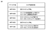
本開示に係るネットワークシステムにおいて、GWとして動作するMFP100およびこれからGWとして動作するMFP100は、LAN200内の各MFP100におけるジョブの状態を監視する。図5は、各MFP100のジョブ処理状態を管理するためのリストの一例を表わす図である。図5に示されたリストは、たとえば、GWであるMFP100の記憶部160に格納され、適宜更新される。
[8. Job processing status in MFP100]
In the network system according to the present disclosure, the
図5に示されるように、ジョブ処理状態は、実行中のジョブ(上段)とジョブのステータス(下段)とを含む。なお、実行中のジョブが無いMFP100については、ジョブ処理状態はステータスを含まない。図5の例では、MFP100A,100Dについては、ジョブ処理状態として値「実行中のジョブ無し」が設定されている。
As shown in FIG. 5, the job processing state includes a running job (upper row) and a job status (lower row). For the MFP100 that does not have a running job, the job processing status does not include the status. In the example of FIG. 5, for the
MFP100Bについては、値「ファックス受信連携ジョブ実行中」が設定されている。ステータスは、「通信確立処理中」である。すなわち、MFP100Bは、ファックス受信連携ジョブにおいてファックスの送信元とファクシミリ通信を確立するための処理を実行中である。当該通信が確立すると、MFP100Bはファクシミリ文書を受信し、受信したファクシミリ文書をクラウドサーバー400へ送信する。
For the MFP100B, the value "Fax reception cooperation job is being executed" is set. The status is "Communication establishment processing in progress". That is, the
MFP100Cについては、値「スマートスキャンジョブ実行中」が設定されている。ステータスは、「スキャンデータ送信中」である。すなわち、MFP100Cは、スマートスキャンジョブにおいてスキャンデータをクラウドサーバー400へ送信している。
For the MFP100C, the value "smart scan job is being executed" is set. The status is "Sending scan data". That is, the
MFP100Eについては、値「リモートファックスジョブ実行中」が設定されている。ステータスは、「ファクシミリ送信中」である。すなわち、MFP100Eは、リモートファックスジョブにおいて、クラウドサーバー400から受信したファクシミリ文書を指定された送信先にファクシミリ通信によって送信している。
For the MFP100E, the value "remote fax job is being executed" is set. The status is "Sending by Facsimile". That is, in the remote fax job, the
[9.クラウドサーバー400におけるジョブ処理状態]
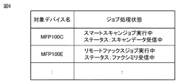
本開示に係るネットワークシステムにおいて、クラウドサーバー400は、LAN200内の各MFP100から送信されているまたは各MFP100に送信されているジョブの状態を管理している。図6は、クラウドサーバー400におけるジョブの状態を管理するためのリストの一例を表わす図である。図6に示されたリストは、たとえば、クラウドサーバー400内の記憶装置に格納され、適宜更新される。
[9. Job processing status in cloud server 400]
In the network system according to the present disclosure, the
図6のリストは、項目「対象デバイス名」と項目「ジョブ処理状態」とを表わす。項目「対象デバイス名」は、ジョブのために確立されているセッションの相手を表わす。項目「ジョブ処理状態」は、ジョブの処理状態を表わす。 The list of FIG. 6 represents the item “target device name” and the item “job processing status”. The item "target device name" represents the session partner established for the job. The item "job processing status" represents the processing status of the job.
図6の例では、クラウドサーバー400は、MFP100B,100C,100Eのそれぞれとの間でセッションを確立させている。MFP100Bについて、クラウドサーバー400は、「ファックス受信連携ジョブ」(ジョブ処理状態)におけるMFP100Bからのファクシミリ文書の送信に向けて待機している。MFP100Cについて、クラウドサーバー400は、「スマートスキャンジョブ」(ジョブ処理状態)におけるMFP100Cからのスキャンデータを受信している。MFP100Eについて、クラウドサーバー400は、「リモートファックスジョブ」(ジョブ処理状態)におけるMFP100Eからのファクシミリ文書を受信している。
In the example of FIG. 6, the
[10.処理の流れ]
図7は、本開示に係るネットワークシステムにおいて、GWがMFP100AからMFP100Bに切り替えられるときの処理の流れを示す図である。図7の処理は、たとえば、MFP100AがGWとして動作している状況において、MFP100BにGWとして動作する指示が入力されたことをトリガーとして開始される。
[10. Processing flow]
FIG. 7 is a diagram showing a processing flow when the GW is switched from the
ステップS10にて、MFP100BのCPU150は、MFP100Aに対して、クラウドサーバー400との間でトンネル通信を確立するための情報(ゲートウェイID:GWID)を要求する。ステップS10にて、MFP100BのCPU150は、さらにクラウドサーバー400のIP(Internet Protocol)アドレス等の、クラウドサーバー400に接続するための情報を要求してもよい。
In step S10, the
ステップS12にて、MFP100AのCPU150は、MFP100Bに対して、GWIDを通知する。ステップS12にて、MFP100AのCPU150は、MFP100Bに対して、さらにクラウドサーバー400に接続するための情報を送信してもよい。
In step S12, the
ステップS14にて、MFP100BのCPU150は、クラウドサーバー400に、LAN200内のMFP100との間での実行中のジョブの状態を問合せる。
In step S14, the
ステップS16にて、クラウドサーバー400は、MFP100Bに対して、LAN200内のMFP100との間での実行中のジョブの状態を回答する。クラウドサーバー400からの回答は、たとえば、図6に示されたリストによって特定される情報の送信である。
In step S16, the
ステップS18にて、MFP100BのCPU150は、クラウドサーバー400からMFP100A〜100Eにジョブ送信が要求されているジョブが無いかどうかを判断する。当該ジョブの一例は「リモートプリント」である。他の例は「リモートファックス」である。ある実施の形態において、CPU150は、クラウドサーバー400から受信したリストにおいて、「ジョブ処理状態」として「リモートプリント」または「リモートファックス」が含まれていない場合には上記ジョブが無いと判断し、含まれている場合には上記ジョブがあると判断する。CPU150は、上記ジョブが無いと判断するとステップS20へ制御を進め、上記ジョブがあると判断するとステップS14へ制御を戻す。
In step S18, the
ステップS20にて、MFP100BのCPU150は、LAN200内のMFP100であって、MFP100A(現在GWとして動作している)の支配下にあるMFP100のそれぞれに、各MFP100からクラウドサーバー400へジョブ送信を要求しているジョブの有無を問い合わせる。「支配下」にあるMFP100とは、GWとしてMFP100Aを利用してクラウドサーバー400と通信するMFP100を意味し、図1の例ではMFP100A〜100Eである。
In step S20, the
ステップS22にて、各MFP100は、MFP100Bに対してジョブの状態を回答する。MFP100BのCPU150は、各MFP100からの回答を受信し、受信した回答を記憶部160等に格納する。これにより、MFP100Bにおいて、たとえば図5に示されたようなリストが生成される。
In step S22, each
ステップS24にて、MFP100BのCPU150は、すべてのMFP100について、MFP100からクラウドサーバー400にジョブ送信が要求されているジョブが無いかどうかを判断する。当該ジョブの一例は、「スマートスキャン」である。他の例は、「プルプリント」である。さらに他の例は、「ファックス受信連携ジョブ」である。
In step S24, the
ある実施の形態において、MFP100BのCPU150は、ステップS22において作成されたリストに、すべてのMFP100について「スマートスキャン」「プルプリント」および「ファックス受信連携ジョブ」が含まれていなければ、すべてのMFP100について、MFP100からクラウドサーバー400に送信されているジョブは無いと判断し、ステップS26へ制御を進める。一方、CPU150は、当該リストに、「スマートスキャン」「プルプリント」および「ファックス受信連携ジョブ」のいずれかが含まれていれば、ステップS14へ制御を戻す。
In one embodiment, the
ステップS26にて、MFP100BのCPU150は、クラウドサーバー400に対してGWの設定の切替の指示を送信する。より具体的には、当該指示は、クラウドサーバー400に対して、LAN200のGWをMFP100AからMFP100Bへ切り替えることを指示する。
In step S26, the
ステップS28にて、MFP100BのCPU150は、MFP100Aの支配下にある全てのMFP100に対してGWの設定の切替の指示を送信する。
In step S28, the
ステップS30にて、MFP100BのCPU150は、クラウドサーバー400とトンネル接続を確立する。この場合、クラウドサーバー400は、ステップS26において送信された情報を利用して、MFP100BがGWであることを認識し、MFP100Bとのトンネル接続を確立する。
In step S30, the
図7の処理によれば、LAN200では、MFP100とクラウドサーバー400との間でジョブが送信されていない状態でGWが切り替えられる。これにより、LAN200におけるクラウドサービスの提供においてダウンタイムは発生しない。また、各MFP100は、作業員による操作ではなく、MFP100Bからの指示に応じて、GWの設定を変更する。これにより、作業員が各MFP100を操作するという煩雑な作業を省略することができ、また、当該操作によるGWの設定ミスが極力回避され得る。
According to the process of FIG. 7, in the
[11.クラウドサーバー400への設定切替指示後のジョブの送信]
図7のステップS26においてクラウドサーバー400に設定切替の指示が送信された後、ステップS28において各MFP100に設定切替の指示が送信される前に、MFP100からクラウドサーバー400にジョブが送信された状況において場合の処理について説明する。図8は、本開示に係るネットワークシステムの挙動の一例を示す図である。
[11. Sending a job after instructing to switch settings to the cloud server 400]
In a situation where a job is transmitted from the
図8において「(1)」が付されて示されるように、MFP100は、MFP100A(切替前のGW)にジョブ送信を要求する。これに応じて、MFP100AのCPU150は、「(2)」が付されて示されるように、クラウドサーバー400に対してジョブ送信を要求する。
As shown by adding "(1)" in FIG. 8, the
クラウドサーバー400は、既にステップS26(図7)にて、MFP100BからGWの設定切替の指示を受信している。したがって、「(3)」が付されて示されるように、MFP100A(現GW)からの(2)のジョブ送信の要求に対して、応答(Res)の送信を所定時間遅らせる。
The
一方、MFP100Bは、ステップS24にて全てのMFP100からジョブが送信されていないと判断した後、MFP100Aの支配下にあるMFP100の状態をウォッチング(監視)する。上記ウォッチングにより、MFP100Bは、「(4)」が付されて示されるように、「(1)」のジョブ送信の要求を認識する。
On the other hand, after determining that jobs have not been transmitted from all the
「(5)」が付されて示されるように、MFP100BのCPU150は、クラウドサーバー400とのトンネル接続を確立する。当該トンネル接続の確立は、図7のステップS30の制御に相当する。
As indicated by "(5)", the
次に、「(6)」が付されて示されるように、MFP100BのCPU150は、「(1)」のジョブ送信を要求したMFP100から、ジョブのデータを取得する。当該ジョブのデータの取得は、たとえば、MFP100Bから当該MFP100にジョブのデータの送信を要求し、当該要求に応じて当該MFP100がMFP100Bにジョブのデータを送信することによって実現される。
Next, as shown by adding "(6)", the
次に、「(7)」が付されて示されるように、MFP100BのCPU150は、「(1)」のジョブ要求の送信をクラウドサーバー400へ送信する。
Next, as indicated by "(7)", the
次に、「(8)」が付されて示されるように、MFP100BのCPU150は、「(1)」のジョブ要求を送信したMFP100に対して、LAN200内のGWをMFP100AからMFP100Bへ切り替えるように設定を変更することを指示する。
Next, as indicated by "(8)", the
以上、図8を参照して説明された処理によれば、MFP100Bがクラウドサーバー400へ設定切替を指示(ステップS26)した後にMFP100がMFP100Aを介してクラウドサーバー400にジョブ送信を要求した場合であっても、改めて、当該ジョブ送信がMFP100Bを介してクラウドサーバー400に要求される。これによる、(1)のジョブ送信の要求に対するResが、クラウドサーバー400からMFP100B(切替後のGW)を介して、MFP100へ送信される。
According to the process described with reference to FIG. 8, the case where the
図8の(3)の「所定時間」は、クラウドサーバー400がMFP100Aからジョブ送信の要求((2))を受けてから、MFP100Bからジョブ送信の要求((7))を受けるまでに想定される時間の長さを少し上回るように設定される。具体的な値は、たとえば、クラウドネットワーク300におけるデータ伝送速度等の具体的な条件に従って設定され得る。
The “predetermined time” in (3) of FIG. 8 is assumed from the time when the
[12.ジョブの状態の問合せに回答できなかったMFP100が存在した場合]
図7のステップS20においてジョブの状態が問合せられたときに、電源OFFなどで当該問合せに回答できない状態のMFP100が存在した場合の処理について説明する。
[12. When there is an MFP100 that could not answer the job status inquiry]
When the job status is inquired in step S20 of FIG. 7, processing will be described when there is an
ある実施の形態では、図7のステップS24における、すべてのMFP100がクラウドサーバー400へジョブ送信の要求を送信していない状態(セッションが確立されていない状態)であるかどうかの判断は、LAN200内の全てのMFP100を対象としてもよいし、MFP100Bが問合せ(ステップS20)の送信から所定時間(実施されるシステムにおいて適宜設定される)内に回答(ステップS22)を受信しなかったMFP100を除外してもよい。
In one embodiment, in step S24 of FIG. 7, it is determined in the
[13.設定切替の指示の受領が確認できなかったMFP100が存在した場合]
図7のステップS28において設定切替の指示が送信されたときに、電源OFFなどで当該指示を受信できない状態のMFP100が存在した場合の処理について説明する。
[13. When there is an MFP100 whose receipt of the setting switching instruction could not be confirmed]
A process will be described when the
ある実施の形態において、CPU150は、ステップS28にて、MFP100Aの支配下のMFP100に設定切替の指示を送信する。各MFP100は、当該指示を受信すると、MFP100Bに受領の応答を送信する。MFP100BのCPU150は、受領の応答を受信しなかったMFP100を特定し、特定されたMFP100のそれぞれからのジョブ送信の要求の有無をウォッチングしてもよい。そして、MFP100BのCPU150は、当該特定されたMFP100からのジョブ送信の要求の送信を検出すると、図8に示されたようなスキムに従って、要求の対象となったジョブデータを取得し、クラウドサーバー400へジョブ送信の要求を送信してもよい。
In one embodiment, the
[14.その他の変形例]
ある実施の形態では、MFP100Aがゲートウェイ(中継装置)として動作しているネットワークシステムにおいて、ゲートウェイがMFP100AからMFP100Bへ切り替えられるとき、クラウドサーバー400と全てのMFP100との間でデータの送受信が無い場合に、MFP100Bは、クラウドサーバー400と各MFP100に当該MFP100Bを新GWとして設定することを指示する。MFP100Aは、LAN200において中継装置として動作している「他の装置」の一例である。クラウドサーバー400と全てのMFP100との間のデータの送受信が無い場合の一例は、クラウドサーバー400と全てのMFP100との間でセッションが確立されていない場合(ステップS18およびステップS24においてYES)である。
[14. Other variants]
In one embodiment, in a network system in which the
他の実施の形態では、クラウドサーバー400とMFP100との間でセッションが確立していていも、クラウドサーバー400とMFP100との間でジョブに係るデータの送受信が無い場合には、MFP100Bは、クラウドサーバー400と各MFP100に当該MFP100Bを新GWとして設定することを指示する。
In another embodiment, even if a session is established between the
ジョブに係るデータの送受信が無い場合の一例は、MFP100が、ファックス受信連携ジョブが実行中であるが、ファクシミリ文書の送信元との間でファクシミリ通信を確立させている等の、ファクシミリ文書をクラウドサーバー400に送信する前の状態にあるときである。ジョブに係るデータの送受信が無い場合の他の例は、MFP100が、スマートスキャンジョブを実行中であるが、スキャンデータをクラウドサーバー400に送信する前の状態(スキャンデータを生成中等)にあるときである。ジョブに係るデータの送受信が無い場合のさらに他の例は、クラウドサーバー400が、リモートプリントジョブまたはリモートファックスジョブに係るジョブ送信を要求している場合であって、MFP100にデータを送信していない状態にあることである。
As an example of the case where there is no transmission / reception of data related to the job, the MFP100 cloud the facsimile document, for example, the fax reception cooperation job is being executed, but the facsimile communication is established with the sender of the facsimile document. This is the state before sending to the
以上説明された本開示では、GWは、画像処理装置と一体的に構成されていた。すなわち、MFP100は、画像処理部151等の画像処理装置としての構成を備え、かつ、所定のプログラムを実行すること等によりゲートウェイ機能40を実現するCPU150を備えていた。なお、GWは、画像処理装置と一体的に構成されていなくてもよい。
In the present disclosure described above, the GW is integrally configured with the image processing device. That is, the
今回開示された各実施の形態は全ての点で例示であって制限的なものではないと考えられるべきである。本発明の範囲は上記した説明ではなくて特許請求の範囲によって示され、特許請求の範囲と均等の意味および範囲内での全ての変更が含まれることが意図される。また、実施の形態および各変形例において説明された発明は、可能な限り、単独でも、組合わせても、実施することが意図される。 It should be considered that each embodiment disclosed this time is exemplary in all respects and is not restrictive. The scope of the present invention is shown by the scope of claims rather than the above description, and is intended to include all modifications within the meaning and scope equivalent to the scope of claims. Further, the inventions described in the embodiments and the modifications thereof are intended to be carried out alone or in combination as much as possible.
40 ゲートウェイ機能、50 HTTPリクエスト、51 ヘッダー、52 ボディ、52A 印刷データ、100,100A〜100E MFP、150 CPU、160 記憶部、170 操作パネル、171 ディスプレイ、172 操作部、300 クラウドネットワーク、400 クラウドサーバー、500 クライアント。 40 gateway function, 50 HTTP request, 51 header, 52 body, 52A print data, 100, 100A-100E MFP, 150 CPU, 160 storage, 170 operation panel, 171 display, 172 operation unit, 300 cloud network, 400 cloud server , 500 clients.
Claims (9)
プロセッサーとを備えた中継装置であって、
前記プロセッサーは、
前記画像処理装置と前記サーバーとの間のデータの送受信が発生しないときに、前記画像処理装置および前記サーバーに、前記所定のネットワークのゲートウェイとして前記中継装置を指定することを通知するように構成されており、
前記サーバーに前記所定のネットワークのゲートウェイとして前記中継装置を指定することを通知した後、前記画像処理装置が前記所定のネットワークにおいて中継装置として動作している他の装置を介して前記サーバーにジョブ送信の要求を送信した場合には、当該要求を前記サーバーに送信するように構成されており、
前記画像処理装置と前記サーバーとの間のデータの送受信が発生しないときは、前記画像処理装置と前記サーバーとの間でジョブに関する接続が確立されているときであって、前記画像処理装置と前記サーバーとの間でデータの送受信が発生していないときを含む、中継装置。 An image processing device in a predetermined network and a communication interface capable of communicating with a server outside the predetermined network.
It is a relay device equipped with a processor.
The processor
It is configured to notify the image processing device and the server that the relay device is designated as the gateway of the predetermined network when data transmission / reception between the image processing device and the server does not occur. And
After notifying the server that the relay device is designated as the gateway of the predetermined network, the image processing device transmits a job to the server via another device operating as the relay device in the predetermined network. When the request is sent, the request is configured to be sent to the server .
When data transmission / reception does not occur between the image processing device and the server, it means that a job-related connection is established between the image processing device and the server, and the image processing device and the server are described. A relay device , including when no data is being sent or received to or from the server.
前記プログラムは、前記コンピューターに、
前記画像処理装置と前記サーバーとの間のデータの送受信が発生しているか否かを判断するステップと、
前記画像処理装置と前記サーバーとの間のデータの送受信が発生していない場合に、前記画像処理装置および前記サーバーに、前記所定のネットワークのゲートウェイとして前記コンピューターを指定することを通知するステップと、
前記サーバーに前記所定のネットワークのゲートウェイとして前記コンピューターを指定することを通知した後、前記画像処理装置が前記所定のネットワークにおいて中継装置として動作している他の装置を介して前記サーバーにジョブ送信の要求を送信した場合に、当該要求を前記サーバーに送信するステップと、を実行させ、
前記画像処理装置と前記サーバーとの間のデータの送受信が発生しないときは、前記画像処理装置と前記サーバーとの間でジョブに関する接続が確立されているときであって、前記画像処理装置と前記サーバーとの間でデータの送受信が発生していないときを含む、プログラム。 A program executed by a computer having an image processing device in a predetermined network and a communication interface capable of communicating with a server outside the predetermined network.
The program is applied to the computer.
A step of determining whether or not data has been transmitted / received between the image processing device and the server, and
A step of notifying the image processing device and the server of designating the computer as a gateway of the predetermined network when data transmission / reception has not occurred between the image processing device and the server.
After notifying the server that the computer is designated as the gateway of the predetermined network, the image processing device sends a job to the server via another device operating as a relay device in the predetermined network. When a request is sent, the step of sending the request to the server and the step of sending the request are executed .
When data transmission / reception does not occur between the image processing device and the server, it means that a job-related connection is established between the image processing device and the server, and the image processing device and the server are described. A program , including when no data is being sent or received to or from the server.
前記所定のネットワーク外のサーバーと、
前記画像処理装置と前記サーバーとの間を中継するための第1の中継装置および第2の中継装置とを備え、
前記第2の中継装置は、
前記所定のネットワーク内の1台以上の画像処理装置、および、前記所定のネットワーク外のサーバーと通信可能な通信インターフェースと、
プロセッサーとを含み、
前記プロセッサーは、
前記画像処理装置と前記サーバーとの間のデータの送受信が発生しない場合に、前記画像処理装置および前記サーバーに、前記所定のネットワークのゲートウェイとして前記第2の中継装置を指定することを通知し、
前記サーバーに前記所定のネットワークのゲートウェイとして前記第2の中継装置を指定することを通知した後、前記画像処理装置が前記所定のネットワークにおいて中継装置として動作している前記第1の中継装置を介して前記サーバーにジョブ送信の要求を送信した場合に、当該要求を前記サーバーに送信する、ように構成されており、
前記画像処理装置と前記サーバーとの間のデータの送受信が発生しない場合は、前記画像処理装置と前記サーバーとの間でジョブに関する接続が確立されているときであって、前記画像処理装置と前記サーバーとの間でデータの送受信が発生していないときを含む、ネットワークシステム。 Image processing equipment in a given network and
With a server outside the specified network
A first relay device and a second relay device for relaying between the image processing device and the server are provided.
The second relay device is
A communication interface capable of communicating with one or more image processing devices in the predetermined network and a server outside the predetermined network.
Including processor
The processor
When data transmission / reception between the image processing device and the server does not occur, the image processing device and the server are notified that the second relay device is designated as the gateway of the predetermined network.
After notifying the server that the second relay device is designated as the gateway of the predetermined network, the image processing device operates as the relay device in the predetermined network via the first relay device. When a job transmission request is sent to the server, the request is sent to the server .
When data transmission / reception does not occur between the image processing device and the server, it is when the connection related to the job is established between the image processing device and the server, and the image processing device and the server are described. A network system , including when no data is being sent or received to or from the server.
Priority Applications (1)
| Application Number | Priority Date | Filing Date | Title |
|---|---|---|---|
| JP2017139164A JP6981069B2 (en) | 2017-07-18 | 2017-07-18 | Relays, programs, and network systems |
Applications Claiming Priority (1)
| Application Number | Priority Date | Filing Date | Title |
|---|---|---|---|
| JP2017139164A JP6981069B2 (en) | 2017-07-18 | 2017-07-18 | Relays, programs, and network systems |
Publications (2)
| Publication Number | Publication Date |
|---|---|
| JP2019018461A JP2019018461A (en) | 2019-02-07 |
| JP6981069B2 true JP6981069B2 (en) | 2021-12-15 |
Family
ID=65354891
Family Applications (1)
| Application Number | Title | Priority Date | Filing Date |
|---|---|---|---|
| JP2017139164A Active JP6981069B2 (en) | 2017-07-18 | 2017-07-18 | Relays, programs, and network systems |
Country Status (1)
| Country | Link |
|---|---|
| JP (1) | JP6981069B2 (en) |
Family Cites Families (4)
| Publication number | Priority date | Publication date | Assignee | Title |
|---|---|---|---|---|
| JP2013005126A (en) * | 2011-06-15 | 2013-01-07 | Hitachi Ltd | Communication system and gateway device |
| CN103517252A (en) * | 2012-06-21 | 2014-01-15 | 中兴通讯股份有限公司 | Packet gateway identification information updating method, AAA server and packet gateway |
| JP5975955B2 (en) * | 2013-08-30 | 2016-08-23 | 株式会社Kddi研究所 | Device device setting method in gateway device, device device setting system, and device device setting program |
| JP6264330B2 (en) * | 2015-06-15 | 2018-01-24 | コニカミノルタ株式会社 | COMMUNICATION SYSTEM, COMMUNICATION RELAY DEVICE, AND PROGRAM |
-
2017
- 2017-07-18 JP JP2017139164A patent/JP6981069B2/en active Active
Also Published As
| Publication number | Publication date |
|---|---|
| JP2019018461A (en) | 2019-02-07 |
Similar Documents
| Publication | Publication Date | Title |
|---|---|---|
| JP4850761B2 (en) | Event notification device and event notification method | |
| JP6056795B2 (en) | Image processing system, gateway device, gateway device control method, gateway device control program | |
| US9549096B2 (en) | Image processing system, relay server, and program for relaying communications | |
| JP6623797B2 (en) | Communication system, communication relay device and program | |
| JP6766641B2 (en) | Image processing device, its control method and program | |
| US9569145B2 (en) | Gateway apparatus | |
| JP2019129427A (en) | Communication apparatus and computer program | |
| JP5929946B2 (en) | Image forming system, relay server, communication control method, and program | |
| JP6981069B2 (en) | Relays, programs, and network systems | |
| US8958098B2 (en) | Communication device allowing proxy reception of data directed thereto, and control method and storage medium therefor | |
| JP2008186271A (en) | Server, printer and network printing system | |
| JP6794281B2 (en) | Information processing device, control method of information processing device, and program | |
| JP6380453B2 (en) | Image forming system, relay server, communication control method, and program | |
| JP6256506B2 (en) | Information processing apparatus, information processing system, server, and program | |
| JP7010028B2 (en) | Image processing equipment and control program | |
| JP2018191151A (en) | Network system, communication device, and computer program | |
| JP2014007495A (en) | Communication apparatus, communication control method, and program | |
| JP4762180B2 (en) | Image transfer device, image reception device, and image transfer system including the same | |
| JP5981318B2 (en) | Data transmission apparatus, image forming apparatus, and data transmission method | |
| JP6447263B2 (en) | Facsimile apparatus, image forming apparatus, and program | |
| CN105282367B (en) | The control method of communication control unit, communication system and communication control unit | |
| JP4262589B2 (en) | Facsimile apparatus, communication system, transmission method, and transmission program | |
| US11467787B2 (en) | Communication system, first server, second server, non-transitory computer-readable recording medium storing computer-readable instructions for first server and non-transitory computer-readable recording medium storing computer-readable instructions for second server | |
| JP7110739B2 (en) | Communication control device, communication control program and network communication system | |
| JP4486441B2 (en) | Facsimile delivery confirmation method |
Legal Events
| Date | Code | Title | Description |
|---|---|---|---|
| A621 | Written request for application examination |
Free format text: JAPANESE INTERMEDIATE CODE: A621 Effective date: 20200615 |
|
| A131 | Notification of reasons for refusal |
Free format text: JAPANESE INTERMEDIATE CODE: A131 Effective date: 20210406 |
|
| A521 | Written amendment |
Free format text: JAPANESE INTERMEDIATE CODE: A523 Effective date: 20210607 |
|
| A02 | Decision of refusal |
Free format text: JAPANESE INTERMEDIATE CODE: A02 Effective date: 20210615 |
|
| A521 | Written amendment |
Free format text: JAPANESE INTERMEDIATE CODE: A523 Effective date: 20210915 |
|
| C60 | Trial request (containing other claim documents, opposition documents) |
Free format text: JAPANESE INTERMEDIATE CODE: C60 Effective date: 20210915 |
|
| A911 | Transfer to examiner for re-examination before appeal (zenchi) |
Free format text: JAPANESE INTERMEDIATE CODE: A911 Effective date: 20210928 |
|
| C21 | Notice of transfer of a case for reconsideration by examiners before appeal proceedings |
Free format text: JAPANESE INTERMEDIATE CODE: C21 Effective date: 20211005 |
|
| TRDD | Decision of grant or rejection written | ||
| A01 | Written decision to grant a patent or to grant a registration (utility model) |
Free format text: JAPANESE INTERMEDIATE CODE: A01 Effective date: 20211019 |
|
| A61 | First payment of annual fees (during grant procedure) |
Free format text: JAPANESE INTERMEDIATE CODE: A61 Effective date: 20211101 |
|
| R150 | Certificate of patent or registration of utility model |
Ref document number: 6981069 Country of ref document: JP Free format text: JAPANESE INTERMEDIATE CODE: R150 |