JP6980439B2 - Sheet transfer device - Google Patents
Sheet transfer device Download PDFInfo
- Publication number
- JP6980439B2 JP6980439B2 JP2017143101A JP2017143101A JP6980439B2 JP 6980439 B2 JP6980439 B2 JP 6980439B2 JP 2017143101 A JP2017143101 A JP 2017143101A JP 2017143101 A JP2017143101 A JP 2017143101A JP 6980439 B2 JP6980439 B2 JP 6980439B2
- Authority
- JP
- Japan
- Prior art keywords
- sheet
- diagonal feed
- roller
- transport
- diagonal
- Prior art date
- Legal status (The legal status is an assumption and is not a legal conclusion. Google has not performed a legal analysis and makes no representation as to the accuracy of the status listed.)
- Active
Links
Images


Classifications
-
- G—PHYSICS
- G03—PHOTOGRAPHY; CINEMATOGRAPHY; ANALOGOUS TECHNIQUES USING WAVES OTHER THAN OPTICAL WAVES; ELECTROGRAPHY; HOLOGRAPHY
- G03G—ELECTROGRAPHY; ELECTROPHOTOGRAPHY; MAGNETOGRAPHY
- G03G15/00—Apparatus for electrographic processes using a charge pattern
- G03G15/65—Apparatus which relate to the handling of copy material
- G03G15/6502—Supplying of sheet copy material; Cassettes therefor
- G03G15/6511—Feeding devices for picking up or separation of copy sheets
-
- G—PHYSICS
- G03—PHOTOGRAPHY; CINEMATOGRAPHY; ANALOGOUS TECHNIQUES USING WAVES OTHER THAN OPTICAL WAVES; ELECTROGRAPHY; HOLOGRAPHY
- G03G—ELECTROGRAPHY; ELECTROPHOTOGRAPHY; MAGNETOGRAPHY
- G03G15/00—Apparatus for electrographic processes using a charge pattern
- G03G15/06—Apparatus for electrographic processes using a charge pattern for developing
- G03G15/08—Apparatus for electrographic processes using a charge pattern for developing using a solid developer, e.g. powder developer
- G03G15/0822—Arrangements for preparing, mixing, supplying or dispensing developer
- G03G15/0865—Arrangements for supplying new developer
-
- G—PHYSICS
- G03—PHOTOGRAPHY; CINEMATOGRAPHY; ANALOGOUS TECHNIQUES USING WAVES OTHER THAN OPTICAL WAVES; ELECTROGRAPHY; HOLOGRAPHY
- G03G—ELECTROGRAPHY; ELECTROPHOTOGRAPHY; MAGNETOGRAPHY
- G03G15/00—Apparatus for electrographic processes using a charge pattern
- G03G15/14—Apparatus for electrographic processes using a charge pattern for transferring a pattern to a second base
- G03G15/16—Apparatus for electrographic processes using a charge pattern for transferring a pattern to a second base of a toner pattern, e.g. a powder pattern, e.g. magnetic transfer
- G03G15/1605—Apparatus for electrographic processes using a charge pattern for transferring a pattern to a second base of a toner pattern, e.g. a powder pattern, e.g. magnetic transfer using at least one intermediate support
- G03G15/1615—Apparatus for electrographic processes using a charge pattern for transferring a pattern to a second base of a toner pattern, e.g. a powder pattern, e.g. magnetic transfer using at least one intermediate support relating to the driving mechanism for the intermediate support, e.g. gears, couplings, belt tensioning
-
- G—PHYSICS
- G03—PHOTOGRAPHY; CINEMATOGRAPHY; ANALOGOUS TECHNIQUES USING WAVES OTHER THAN OPTICAL WAVES; ELECTROGRAPHY; HOLOGRAPHY
- G03G—ELECTROGRAPHY; ELECTROPHOTOGRAPHY; MAGNETOGRAPHY
- G03G15/00—Apparatus for electrographic processes using a charge pattern
- G03G15/60—Apparatus which relate to the handling of originals
- G03G15/602—Apparatus which relate to the handling of originals for transporting
-
- G—PHYSICS
- G03—PHOTOGRAPHY; CINEMATOGRAPHY; ANALOGOUS TECHNIQUES USING WAVES OTHER THAN OPTICAL WAVES; ELECTROGRAPHY; HOLOGRAPHY
- G03G—ELECTROGRAPHY; ELECTROPHOTOGRAPHY; MAGNETOGRAPHY
- G03G15/00—Apparatus for electrographic processes using a charge pattern
- G03G15/20—Apparatus for electrographic processes using a charge pattern for fixing, e.g. by using heat
- G03G15/2003—Apparatus for electrographic processes using a charge pattern for fixing, e.g. by using heat using heat
- G03G15/2014—Apparatus for electrographic processes using a charge pattern for fixing, e.g. by using heat using heat using contact heat
- G03G15/2017—Structural details of the fixing unit in general, e.g. cooling means, heat shielding means
- G03G15/2028—Structural details of the fixing unit in general, e.g. cooling means, heat shielding means with means for handling the copy material in the fixing nip, e.g. introduction guides, stripping means
-
- G—PHYSICS
- G03—PHOTOGRAPHY; CINEMATOGRAPHY; ANALOGOUS TECHNIQUES USING WAVES OTHER THAN OPTICAL WAVES; ELECTROGRAPHY; HOLOGRAPHY
- G03G—ELECTROGRAPHY; ELECTROPHOTOGRAPHY; MAGNETOGRAPHY
- G03G2215/00—Apparatus for electrophotographic processes
- G03G2215/00362—Apparatus for electrophotographic processes relating to the copy medium handling
- G03G2215/00919—Special copy medium handling apparatus
- G03G2215/00945—Copy material feeding speed varied over the feed path
Description
本発明は、シートを搬送するシート搬送装置に関する。 The present invention relates to a sheet transport device for transporting sheets.
画像形成装置においてシートを搬送するシート搬送装置には、シートに対してサイドレジストレーション方式の斜行補正を行うものがある。このようなシート搬送装置では、斜送ローラによってシートをシート搬送路の側方に配置された基準部材に幅寄せし、シートの側端を基準部材に当接させることでシートの傾きを補正する。例えば、特許文献1には、用紙搬送路に沿って複数配置されたローラによって用紙の側端を基準ガイドに当接させて斜行補正を行う用紙整合装置が記載されている。
Some of the sheet transport devices that transport the sheet in the image forming apparatus perform skew correction of the side registration method with respect to the sheet. In such a sheet transfer device, the sheet is moved to the reference member arranged on the side of the sheet transfer path by the diagonal feed roller, and the side edge of the sheet is brought into contact with the reference member to correct the inclination of the sheet. .. For example,
ところで、サイドレジストレーション方式において、基準部材に対する角度が小さい方向に沿って基準部材にシートが幅寄せされる場合、基準部材に当接するまでにシートは比較的長い距離を搬送されることになる。この場合、例えば幅寄せ中に斜送ローラより上流の搬送ローラ対のニップを開放させる構成等、シートの幅方向の移動に対応するための構成によって装置が複雑化又は大型化してしまう。一方、幅寄せを行う際のシートの移動方向を、基準部材に対する角度が大きくなるように構成した場合、シートの側端が基準部材に強く突き当たってシートの座屈が生じる懸念がある。 By the way, in the side registration method, when the sheet is width-aligned to the reference member along a direction in which the angle with respect to the reference member is small, the sheet is transported a relatively long distance before coming into contact with the reference member. In this case, the apparatus becomes complicated or large due to the configuration for supporting the movement of the sheet in the width direction, such as a configuration in which the nip of the transport roller pair upstream from the diagonal feed roller is opened during the width adjustment. On the other hand, when the moving direction of the seat when the width is adjusted is configured so that the angle with respect to the reference member is large, there is a concern that the side edge of the seat strongly abuts against the reference member and buckling of the seat occurs.
そこで、本発明は、シートの座屈を回避しつつ、短い搬送距離でシートの斜行補正を行うことができるシート搬送装置を提供することを目的とする。 Therefore, an object of the present invention is to provide a seat transport device capable of correcting the skew of a seat in a short transport distance while avoiding buckling of the seat.
本発明の一態様に係るシート搬送装置は、シート搬送方向に沿って延び、前記シート搬送方向に直交する幅方向におけるシートの端部に当接可能な当接面を有する当接部材と、シートの移動方向が前記シート搬送方向に対して第1方向に傾斜するように設けられ、前記第1方向と直交する軸線を中心に回転可能であり、前記幅方向において前記当接面に近づくようにシートを斜送する第1斜送ローラと、シートの移動方向が前記シート搬送方向に対して第2方向に傾斜するように設けられ、前記第2方向と直交する軸線を中心に回転可能であり、前記幅方向において前記当接面に近づくようにシートを斜送する第2斜送ローラと、前記シート搬送方向において前記第1斜送ローラ及び前記第2斜送ローラの上流に設けられ、前記シート搬送方向にシートを搬送する搬送ローラと、を備え、前記幅方向において、前記第2斜送ローラは前記搬送ローラによって搬送されるシートの搬送中心線に対して前記当接部材と同じ側に配置され、かつ、前記第1斜送ローラは前記搬送中心線に対して前記当接部材とは反対側に配置され、前記シート搬送方向に対する前記第1方向の角度は、前記シート搬送方向に対する前記第2方向の角度よりも大きく、シートを斜送する際の前記第1斜送ローラの周速度は、シートを斜送する際の前記第2斜送ローラの周速度よりも速い、ことを特徴とする。
本発明の他の一態様に係るシート搬送装置は、シート搬送方向に沿って延び、前記シート搬送方向に直交する幅方向におけるシートの端部に当接可能な当接面を有する当接部材と、シートの移動方向が前記シート搬送方向に対して第1方向に傾斜するように設けられ、前記第1方向と直交する軸線を中心に回転可能であり、前記幅方向において前記当接面に近づくようにシートを斜送する第1斜送ローラと、シートの移動方向が前記シート搬送方向に対して第2方向に傾斜するように設けられ、前記第2方向と直交する軸線を中心に回転可能であり、前記幅方向において前記当接面に近づくようにシートを斜送する第2斜送ローラと、前記シート搬送方向において前記第1斜送ローラ及び前記第2斜送ローラの上流に設けられ、前記シート搬送方向にシートを搬送する搬送ローラ対と、前記搬送ローラ対を、シートを挟持して搬送可能なニップ部を形成する当接状態と、前記ニップ部が開放される離間状態と、に切換える切換手段と、を備え、前記幅方向において、前記第2斜送ローラは前記搬送ローラ対によって搬送されるシートの搬送中心線に対して前記当接部材と同じ側に配置され、かつ、前記第1斜送ローラは前記搬送中心線に対して前記当接部材とは反対側に配置され、前記シート搬送方向に対する前記第1方向の角度は、前記シート搬送方向に対する前記第2方向の角度よりも大きく、前記搬送ローラ対は、前記当接状態でシートを前記第1斜送ローラに向けて搬送し、前記シート搬送方向におけるシートの先端が前記第1斜送ローラに到達した後に、前記切換手段によって前記当接状態から前記離間状態に切換わる、ことを特徴とする。
The sheet transport device according to one aspect of the present invention includes a contact member extending along the sheet transport direction and having a contact surface capable of contacting an end portion of the sheet in a width direction orthogonal to the sheet transport direction, and a sheet. Is provided so as to be inclined in the first direction with respect to the sheet transport direction, is rotatable about an axis orthogonal to the first direction, and approaches the contact surface in the width direction. a first skew row La to skew the sheet, the direction of movement of the sheet is provided to be inclined in a second direction with respect to the sheet conveying direction, rotatable about an axis perpendicular to the second direction There, a second skew row La to skew the sheet to be closer to the abutment surface in the width direction, upstream of the said in the sheet conveying direction first skew row La及beauty the second skew row La provided, and a conveying row La for conveying the sheet to the sheet conveying direction, in the width direction, the second skew row La whereas conveyance center line of the sheet to be thus conveyed to the conveying row La wherein disposed on the same side as the abutment member Te, and said first skew row La is said contact member with respect to the conveyance center line is disposed on the opposite side, the first direction with respect to the sheet conveying direction The angle of is larger than the angle of the second direction with respect to the sheet transport direction , and the peripheral speed of the first diagonal feed roller when diagonally feeding the sheet is the peripheral speed of the second diagonal feed roller when the sheet is diagonally fed. It is characterized by being faster than the peripheral speed of.
The sheet transport device according to another aspect of the present invention is a contact member having a contact surface extending along the sheet transport direction and capable of contacting the end portion of the sheet in the width direction orthogonal to the sheet transport direction. , The sheet is provided so that the moving direction of the sheet is inclined in the first direction with respect to the sheet transporting direction, is rotatable about an axis orthogonal to the first direction, and approaches the contact surface in the width direction. The first diagonal feeding roller that diagonally feeds the sheet and the sheet are provided so that the moving direction of the sheet is inclined to the second direction with respect to the sheet transporting direction, and the sheet can rotate about an axis orthogonal to the second direction. A second diagonal feed roller that diagonally feeds the sheet so as to approach the contact surface in the width direction, and an upstream of the first diagonal feed roller and the second diagonal feed roller in the sheet transport direction. , A contact state in which a transfer roller pair that conveys a sheet in the sheet transfer direction, a contact state in which the transfer roller pair is sandwiched between the sheets to form a transferable nip portion, and a separated state in which the nip portion is opened. The second diagonal feed roller is arranged on the same side as the contact member with respect to the transport center line of the sheet transported by the transport roller pair in the width direction. The first diagonal feed roller is arranged on the side opposite to the contact member with respect to the transport center line, and the angle of the first direction with respect to the sheet transport direction is the angle of the second direction with respect to the sheet transport direction. The transport roller pair transports the sheet toward the first diagonal feed roller in the contact state, and after the tip of the sheet in the sheet transport direction reaches the first diagonal feed roller, the transport roller pair reaches the first diagonal feed roller. It is characterized in that the contact state is switched to the separated state by the switching means.
本発明に係るシート搬送装置によれば、シートの座屈を回避しつつ、短い搬送距離でシートの斜行補正を行うことができる。 According to the sheet transfer device according to the present invention, it is possible to correct the skew of the sheet in a short transfer distance while avoiding buckling of the sheet.
以下、図面を参照しながら、本開示に係る画像形成装置について説明する。画像形成装置は、プリンタ、複写機、ファクシミリ、及び複合機を含み、外部PCから入力された画像情報や原稿から読取った画像情報に基づいて、記録媒体として用いられるシートに画像を形成する。 Hereinafter, the image forming apparatus according to the present disclosure will be described with reference to the drawings. The image forming apparatus includes a printer, a copying machine, a facsimile, and a multifunction device, and forms an image on a sheet used as a recording medium based on image information input from an external PC or image information read from a manuscript.
(画像形成装置の概要)
本開示に係るシート搬送装置は、図1に示す電子写真方式のフルカラーレーザープリンタである画像形成装置1の一部を構成している。画像形成装置1は、一般事務用途以外の印刷に対応可能なPOD機であり、記録媒体として用紙及び封筒等の紙、光沢紙、オーバーヘッドプロジェクタ用シート(OHT)等のプラスチックフィルム、並びに布等の様々なシートを用いることができる。画像形成装置1の装置本体1Aには、シートSを収納する給送カセット51と、給送カセット51から給送されたシートSに画像を形成する画像形成エンジン10と、が収容されている。画像形成手段の一例である画像形成エンジン10は、イエロー、マゼンタ、シアン、及びブラックのトナー像を形成する4つの画像形成部PY,PM,PC,PKと、中間転写体である中間転写ベルト506と、を備えたタンデム型中間転写方式である。画像形成部PY〜PKは、それぞれ感光体である感光ドラム1Y,1M,1C,1Kを有する電子写真ユニットである。
(Outline of image forming device)
The sheet transport device according to the present disclosure constitutes a part of the
画像形成部PY〜PKは、現像に用いるトナーの色が異なる以外は同様に構成されるため、イエローの画像形成部PYを例に画像形成部の構成及びトナー像の形成プロセス(画像形成動作)について説明する。画像形成部PYは、感光ドラム1Yの他に、露光装置511、現像装置510、及びドラムクリーナ509を有する。感光ドラム1Yは、外周部に感光層を有するドラム状の感光体であり、中間転写ベルト506の回転方向(矢印R2)に沿った方向(矢印R1)に回転する。感光ドラム1Yの表面は、帯電ローラ等の帯電手段から電荷を供給されることで帯電する。露光装置511は、画像情報に応じて変調されたレーザ光を発し、反射装置512を含む光学系によって感光ドラム1Yを走査することで、感光ドラム1Yの表面に静電潜像を描き込む。現像装置510は、トナーを含む現像剤を収容し、感光ドラム1Yにトナーを供給することで静電潜像をトナー像に現像する。感光ドラム1Yに形成されたトナー像は、一次転写装置である一次転写ローラ507と中間転写ベルト506との間のニップ部である一次転写部において中間転写ベルト506に一次転写される。転写後に感光ドラム1Yに残留した残トナーは、ドラムクリーナ509によって除去される。
Since the image forming units PY to PK are configured in the same manner except that the colors of the toners used for development are different, the composition of the image forming unit and the toner image forming process (image forming operation) using the yellow image forming unit PY as an example. Will be explained. The image forming unit PY has an
中間転写ベルト506は、駆動ローラ504、従動ローラ505、二次転写内ローラ503、及び一次転写ローラ507に巻き掛けられ、駆動ローラ504により図中時計回り方向(矢印R2)に回転駆動される。上述の画像形成動作は各画像形成部PY〜PKにおいて並行して進められ、4色のトナー像が互いに重なるように多重転写されることで、中間転写ベルト506にフルカラーのトナー像が形成される。このトナー像は、中間転写ベルト506に担持されて二次転写部に搬送される。二次転写部は、転写手段としての二次転写ローラ56と二次転写内ローラ503の間のニップ部として構成され、二次転写ローラ56にトナーの帯電極性とは逆極性のバイアス電圧が印加されることでトナー像がシートSに二次転写される。転写後に中間転写ベルト506に残留した残トナーは、ベルトクリーナによって除去される。
The
トナー像を転写されたシートSは、定着前搬送部57により定着ユニット58へと受け渡される。定着ユニット58は、シートSを挟持して搬送する定着ローラ対と、ハロゲンヒータ等の熱源とを有し、シートSに担持されたトナー像に圧力及び熱を加える。これにより、トナー粒子が溶融・固着して、シートSに定着した定着画像が得られる。
The sheet S to which the toner image is transferred is delivered to the fixing
次に、給送カセット51に収容されたシートSを給送し、画像が形成されたシートSを機体外部に排出するシート搬送系の構成及び動作について説明する。シート搬送系は、大まかにシート給送部54、レジストレーション部50、分岐搬送部59、反転搬送部501、及び両面搬送部502を含む。
Next, the configuration and operation of the sheet transport system that feeds the sheet S housed in the
給送カセット51は装置本体1Aに対して引抜き可能に装着され、昇降可能な昇降プレート52に積載されたシートSは、給送ユニット53によって1枚ずつ給送される。シート給送手段である給送ユニット53としては、吸引ファンによってベルト部材にシートSを吸着して搬送するベルト方式(図1参照)や、ローラ又はパッドを用いた摩擦分離方式が挙げられる。給送ユニット53から送り出されたシートSは、搬送ローラ対54bによって給送パス54aに沿って搬送され、レジストレーション部50に受け渡される。
The feeding
レジストレーション部50は、プレレジ搬送部20、斜行補正部30、及びレジストレーションローラ対(以下、レジローラとする)7を備え、シートSの斜行を補正してシートSを二次転写部に向けて搬送する。このとき、レジローラ7は、レジストレーションセンサ8の検知信号に基づいて、画像形成部PY〜PKによる画像形成動作の進行度に合わせたタイミングでシートSを二次転写部に送り込む。二次転写部においてトナー像を転写され、定着ユニット58によって画像の定着が行われたシートSは、シートSの搬送経路を切換可能な切換部材を有する分岐搬送部59に搬送される。シートSに対する画像形成が完了している場合には、シートSは排出ローラ対によって装置本体1Aの外方に配置された排出トレイ500に排出される。シートSの裏面に画像を形成する場合、シートSは反転搬送部501を介して両面搬送部502に受け渡される。反転搬送部501は、正転及び逆転可能な反転ローラ対を有し、シートSをスイッチバックさせて両面搬送部502に受け渡す。両面搬送部502は、給送パス54aに合流する再搬送パス54cを介してシートSをプレレジ搬送部20へ向けて搬送する。そして、シートSは裏面に画像を形成された後、排出トレイ500へと排出される。
The
なお、上記構成は画像形成装置の一例であり、例えば、電子写真方式に代えてインクジェット方式の画像形成手段を備えた画像形成装置であってもよい。また、画像形成装置は、画像形成手段を備えた装置本体の他にオプションフィーダやシート処理装置等の付属機器を備えるものがあるが、以下で説明するシート搬送装置の構成はこのような付属機器におけるシートの搬送に用いてもよい。 The above configuration is an example of an image forming apparatus, and for example, an image forming apparatus provided with an inkjet type image forming means instead of the electrophotographic method may be used. Further, the image forming apparatus includes an accessory device such as an optional feeder and a sheet processing device in addition to the apparatus main body provided with the image forming means, and the configuration of the sheet transport device described below is such an accessory device. It may be used for transporting the sheet in.
(サイドレジストレーション)
ここで、斜行補正部30によるシートSの斜行補正について説明する。本開示に係る斜行補正部30は、サイドレジストレーション方式のシート整合装置である。即ち、斜行補正部30は、シート搬送方向に沿って延びる当接面を有する基準部材にシートの側端、つまりシート搬送方向に直交する幅方向の端部を当接させることで、シートの側端が当接面に倣うようにしてシートの斜行を補正する。ただし、シート搬送方向とは、斜行補正部30によってシートSが基準部材に向かって幅寄せされる前のシートの搬送方向であり、本実施例ではプレレジ搬送部20の搬送ローラ対21によるシートSの搬送方向を指すものとする。
(Side registration)
Here, the skew correction of the sheet S by the
図24に示す参考例としての斜行補正部30Aは、基準部材300と、基準部材300に向けてシートSを幅寄せする1つ以上の斜送ローラ32Aとを備える。各斜送ローラ32Aは、シート搬送方向(図中左方向)に沿って延びる基準部材300の基準面301に対して角度αで傾斜した姿勢で配置されている。斜送ローラ32Aは、プレレジ搬送部20の搬送ローラ対21からシート搬送方向の下流に送り出されたシートSに対して図中左下方向の斜めの搬送力を付与することで、シートSの側端を基準面301に当接させる。
As a reference example shown in FIG. 24, the
プレレジ搬送部20の各搬送ローラ対21は、ニップ部にシートSを挟持可能な加圧状態と、ニップ部が開放される離間状態とを切換可能であり、斜送ローラ32AによってシートSの幅寄せが行われている期間中は離間状態に保持される。これは、搬送ローラ対21がシートSの幅寄せを妨げることを防ぐと共に、シートSに対する摩擦やストレスによってシートSのダメージが生じることを避けるためである。
Each
ここで、斜送ローラ32Aの角度αが比較的小さい場合、シートSはシート搬送方向に対して小さな傾斜角度に沿って移動し、基準部材300に向かって徐々に幅寄せされる。即ち、斜送ローラ32AがシートSの幅寄せを開始してからシートSの側端が基準部材300の基準面301に当接するまでの、シート搬送方向におけるシートの移動距離Lαが大きな値となる。しかしながら、少なくとも幅寄せを開始する位置(破線参照)でシートSに当接する可能性のある搬送ローラ対21を開放可能とする必要から、搬送ローラ対21を移動させる機械的構成やその制御構成の分、装置が大型化又は複雑化してしまう。
Here, when the angle α of the
特に、長尺シート、即ちA判及びB判等の広く用いられている規格に比べて長辺と短辺の比が大きいシートの場合、開放可能とする必要のある搬送ローラ対21の数が多くなる。例えば、図1においてシート給送部54から斜行補正部30に至る長さの長尺シートSに対応する場合に、給送パス54aの搬送ローラ対54bを離間させる必要が生じることが考えられる。なお、搬送ローラ対を移動させるための構成の他にも、シートが斜送される区間では例えばシートの搬送抵抗を抑制するためにシート搬送路の湾曲を極力避ける等の対策が必要となり、装置の大型化・複雑化につながる。
In particular, in the case of a long sheet, that is, a sheet having a large ratio of long side to short side compared to widely used standards such as A size and B size, the number of transfer roller pairs 21 that need to be openable is large. Will increase. For example, in the case of corresponding to the long sheet S having a length extending from the
そこで、図24(b)に示すように斜送ローラ32Bの角度βを大きく設定する(β>α)ことが考えられる。斜送ローラ32Bの角度βが大きい程、幅寄せを開始する位置(破線参照)をシート搬送方向の下流側に設定できるため、上流側の搬送ローラ対21を離間させるための構成を省略可能となる。例えば図24(a)の例では4組の搬送ローラ対21(Nα=4)を離間させる必要がある一方で、図24(b)の例では下流側の2組の搬送ローラ対21(Nβ=2)を開放可能とすれば済む。しかし、斜送ローラ32Bの角度βが大きいことから、シートSの側端が基準部材300に対して強く突き当てられてしまい、シートSの座屈が生じる懸念があった。
Therefore, as shown in FIG. 24 (b), it is conceivable to set a large angle β of the
そこで、本開示に係るシート搬送装置は、シート搬送方向に対する傾斜角度が異なる複数の斜送手段を併設することにより、このような不都合を克服している。以下、シート搬送装置の構成及び動作について、具体例に沿って説明する。 Therefore, the sheet transport device according to the present disclosure overcomes such inconvenience by providing a plurality of diagonal feed means having different tilt angles with respect to the sheet transport direction. Hereinafter, the configuration and operation of the sheet transfer device will be described with reference to specific examples.
まず、実施例1に係るシート搬送装置であるレジストレーション部50の構成について説明する。図2に示すように、レジストレーション部50は、シートをシート搬送方向Dxに搬送するプレレジ搬送部20と、プレレジ搬送部20の下流に配置された斜行補正部30と、斜行補正部30の下流に配置されたレジローラ7と、を備える。
First, the configuration of the
プレレジ搬送部20は、少なくとも1組(本実施例では4組)の搬送ローラ対21を有し、各搬送ローラ対21はシート搬送方向DxにシートSを送り出す。プレレジ搬送部20は、シートSをセンター基準方式で、即ちシート搬送方向Dxに直交する幅方向Dyに関してシートSの中心がシート搬送路の中央位置(以下、搬送中心とする)L0に揃うようにシートSを搬送する。搬送中心L0の位置は、本実施例の場合、搬送ローラ対21がシートSを挟持可能な領域、つまりローラ同士の接触領域の幅方向Dyにおける中央位置である。
The
最下流の搬送ローラ対21の近傍かつ搬送中心L0の近傍には、シートSを検知するための検知手段として、プレレジセンサS1が配置されている。プレレジセンサS1は、例えば発光部及び受光部を有する反射型の光電センサを用いることができ、その場合は検知位置に到達したシートSによって発光部が発した光が反射され、受光部が反射光を検出することでシートSの通過タイミングが検知される。
A pre-registration sensor S1 is arranged in the vicinity of the most downstream
斜行補正部30は、基準部材300と、奥側斜送ユニット31と、前側斜送ユニット32と、を備える。ただし、前側・奥側は画像形成装置1を正面から視た場合(図1の視点)の奥行方向における位置関係を表している。基準部材300は、シート搬送方向Dxに延びる基準面301を有し、幅方向Dyに関してシート搬送路のいずれか一方に配置される。基準面301は、シート搬送方向に沿って延び、シートの側端に当接可能な当接面に相当する。
The
奥側斜送ユニット31は、幅方向Dyに関して搬送中心L0の一方側つまり基準部材300の反対側に配置され、前側斜送ユニット32は搬送中心L0の他方側つまり基準部材300と同じ側に配置されている。前側斜送ユニット32及び奥側斜送ユニット31は、それぞれ少なくとも1つの斜送ローラ311,321,322,323を有し、本実施例では奥側斜送ユニット31に1つ、前側斜送ユニット32に3つ配置されている。
The back
奥側及び前側の斜送ローラ311,321〜323は、いずれも幅方向Dyに対して傾斜した軸線を中心に回転する。即ち、第1ローラ(第1斜送ローラ)に相当する奥側の斜送ローラ311は、シートSに対する接触部における接線方向が、シート搬送方向Dxに対してθ1の角度で傾斜した方向となるように配置されている。また、各々が第2ローラ(第2斜送ローラ)に相当する前側の斜送ローラ321〜323は、シートSに対する接触部における接線方向が、シート搬送方向Dxに対してθ2の角度で傾斜した方向となるように、互いに平行に配置されている。従って、各斜送ローラ311,321〜323は、シートSに当接して回転することにより、シート搬送方向Dxの下流に向かう程、幅方向Dyにおいて基準部材300の基準面301に近付くように傾斜した方向の搬送力をシートSに付与する。
The
奥側斜送ユニット31は、シート搬送方向に対して傾斜した第1方向の搬送力をシートに付与してシートを当接面に接近させる第1斜送手段に相当する。前側斜送ユニット32は、幅方向に関して第1斜送手段より当接面に近い位置に配置され、シート搬送方向に対して傾斜した第2方向の搬送力をシートに付与してシートを当接面に当接させる第2斜送手段に相当する。また、プレレジ搬送部20の各搬送ローラ対21及びレジローラ7は、いずれもシートをシート搬送方向に搬送可能なシート搬送手段の一例である。この内、搬送ローラ対21は、第1斜送手段及び第2斜送手段にシートを受け渡す第1搬送手段に相当し、レジローラ7は第1斜送手段及び第2斜送手段によって斜送されたシートを受け取って搬送する第2搬送手段に相当する。
The back-side
ここで、奥側の斜送ローラ311の傾斜角度θ1は、前側の斜送ローラ321〜323の傾斜角度θ2より大きく設定されている(θ1>θ2)。即ち、第1斜送手段がシートに付与する力のシート搬送方向に対する傾斜角度(第1の角度)が、第2斜送手段がシートに付与する力のシート搬送方向に対する傾斜角度(第2の角度)に比べて大きくなるように構成されている。なお、このような構成を備えた構成におけるレジストレーション部50のシート搬送動作及びシートの挙動については、後に詳しく説明する。
Here, the tilt angle θ1 of the
斜行補正部30には、それぞれシートSを検知可能な検知手段として、斜送センサS2及びレジ前センサS3が配置されている。斜送センサS2は、シート搬送方向Dxに関して、斜送ユニット31,32によって斜送されるシートSが基準部材300に当接することが予定される位置の付近に配置される。レジ前センサS3は、シート搬送方向Dxに関して斜送センサS2より下流かつレジローラ7より上流に配置される。斜送センサS2及びレジ前センサS3は、プレレジセンサS1と同様、反射型光電センサ等の既知のセンサを用いることができる。
In the
レジローラ7は、シートSを挟持した状態で幅方向Dyにスライド可能であり、側端が基準部材300の基準面301に当接していたシートSを二次転写部において転写される画像の位置に合わせて幅方向Dyに移動させる。なお、基準部材300及び前側斜送ユニット32も幅方向Dyに移動可能であり、搬送されるシートSの幅に合わせて予め位置決めされる。また、シートとシートに形成する画像との位置調整を行う方法はこれに限らず、例えば基準部材300及びレジローラ7の幅方向位置を固定し、画像形成部PY〜PKが形成するトナー像の主走査方向位置を調整する構成としてもよい。
The
(プレレジ搬送部)
プレレジ搬送部20の構成について、図3及び図4を用いて詳しく説明する。図3(a)、(b)はプレレジ搬送部20の断面構成を示す概略図であり、図4は搬送ローラ対21の駆動構成を示す斜視図である。
(Pre-registration transport section)
The configuration of the
図3(a)、(b)に示すように、プレレジ搬送部20の各搬送ローラ対21は、駆動力が入力される駆動ローラ23と、駆動ローラ23に従動回転する従動ローラ24とで構成される。少なくとも一部の搬送ローラ対21は、ニップ部にシートSを挟持可能な加圧状態(図3(a))と、ニップ部が開放された離間状態(図3(b))とに切換可能である。なお、全ての搬送ローラ対21を加圧状態と離間状態とに切換可能とするかどうかは、画像形成装置がサポートするシートSの最大サイズに応じて決定すればよい。
As shown in FIGS. 3 (a) and 3 (b), each
プレレジ搬送部20には、搬送ローラ対21の加圧状態と離間状態とを切換可能な切換手段として、偏芯コロ103を有するカム機構100が設けられている。偏芯コロ103は、駆動源としてのプレレジ加圧モータMrによってギヤ105,106を介して回転駆動され、外周部のカム面に当接するアーム部材101を揺動させる。アーム部材101は、揺動軸102を中心にステー部材18に対して揺動可能に支持され、揺動軸102の一方側で偏芯コロ103に当接し、他方側で従動ローラ24の回転軸である従動軸26を支持している。アーム部材101の揺動により、従動ローラ24はガイド部材201,202によって形成されるシート搬送路に出没する。従って、ステッピングモータであるプレレジ加圧モータMrを介して偏芯コロ103の回転角を制御することにより、従動ローラ24が駆動ローラ23から離間する離間状態と従動ローラ24が駆動ローラ23に圧接する加圧状態とを切換可能な構成である。
The
図4に示すように、各駆動ローラ23は、駆動ローラ軸25にゴムローラ23aが取付けられて構成され、ベルト伝動機構152を介して駆動源であるプレレジ駆動モータMpに接続されている。各プレレジ駆動モータMpはステッピングモータであり、駆動の開始及び停止のタイミング及び駆動ローラ23の駆動速度(ゴムローラ23aの周速)を変更可能である。
As shown in FIG. 4, each drive
(斜行補正部)
続いて、斜行補正部30の構成について、図5〜図7を用いて詳しく説明する。図5(a)は斜行補正部30を上方から視た概略図であり、図5(b)は基準部材300をシート搬送方向Dxから視た断面構成を示す模式図である。図6(a)は斜送ユニットの加圧構成を示す斜視図であり、図6(b)はその側面図である。図7(a)、(b)は、斜送ユニットの加圧状態及び解除状態を表す模式図である。
(Slanting correction part)
Subsequently, the configuration of the
図5(a)に示すように、前側及び奥側の斜送ローラ311,321〜323は、ユニバーサルジョイント31c,32cを用いて、上記の角度θ1,θ2に合わせて傾斜した状態で回転軸線を固定されている。各斜送ローラ311,321〜323は、ユニバーサルジョイント31c,32c、ベルト31a,32a及びプーリ31b,32bを含む伝動機構を介して駆動源である斜送駆動モータMs1,Ms2に連結されている。斜送駆動モータMs1,Ms2はステッピングモータであり、駆動速度や駆動開始・停止のタイミングを制御可能である。
As shown in FIG. 5A, the
図5(b)に示すように、基準部材300は、シートSの側端が突き当たる基準面301、シートSの上面に対向する上ガイド面302、及びシートSの下面に対向する下ガイド面303からなる凹形状の断面を有する。基準部材300は、アルミのダイキャストで構成され、基準面301を切削加工により高精度化し、さらに基準面301にPTFE(ポリテトラフルオロエチレン)無電解ニッケル加工処理を施したものを好適に用いることができる。こうすることで、平面性が高く、かつすべり性の高い(シートSに対する摩擦抵抗の小さい)基準面301が得られ、シートSの斜行補正の精度向上を図ることができる。
As shown in FIG. 5B, the
図6及び図7に示すように、斜行補正部30には、斜送ローラ320とこれに対向する従動ローラ330とのニップ部(挟持部)にシートSを挟持して搬送可能な加圧状態と、加圧状態が解除される解除状態とを切換可能な加圧機構33が配置される。なお、解除状態とは、ニップ部が開放されている状態に限らず、加圧状態に比べて弱い力でローラ同士が接触している場合を含むものとする。また、斜送ユニットの加圧状態とは少なくとも1つの斜送ローラが加圧状態であることを指し、斜送ユニットの解除状態とは全ての斜送ローラが解除状態であることを指すものとする。
As shown in FIGS. 6 and 7, the
なお、本実施例の斜行補正部30には、図6及び図7に示す斜送ローラ320が斜送ローラ311,321〜323のいずれかに置換えられた状態で、複数組の従動ローラ330及び加圧機構33が配置されている。言い換えると、加圧状態と解除状態を切換可能な切換手段としての加圧機構33は、前側の斜送ローラ321〜323に対応するもの(第2切換手段)と、奥側の斜送ローラ311に対応するもの(第1切換手段)とがそれぞれ設けられている。また、前側斜送ユニット32又は奥側斜送ユニット31の斜送ローラが追加される場合には、追加される斜送ローラの各々に加圧機構33が配置される。
In the
図6(a)、(b)に示すように、加圧機構33はアーム部材332、リンク部材333、加圧ギヤ334、加圧バネ335、及び斜送加圧モータMkを含む。従動ローラ330は、アーム部材332によって従動軸331を中心に回転可能に支持され、アーム部材332の揺動によって斜送ローラ320に対して接近又は離間する方向に移動可能である。本実施例における従動ローラ330は、幅方向に延びる軸線を中心にシート搬送方向に沿って回転するが、対応する斜送ローラと平行な軸線上に配置する構成としてもよい。アーム部材332は、加圧バネ335及びリンク部材333を介して加圧ギヤ334に連結される。加圧ギヤ334は、駆動源である斜送加圧モータMkの出力軸に連結されている。
As shown in FIGS. 6A and 6B, the
図7(a)に示すように、加圧状態においては、加圧ギヤ334が図中反時計回り方向に回動し、加圧バネ335に引っ張られたアーム部材332が揺動軸332aを中心に反時計回り方向に揺動する。これにより、従動ローラ330が斜送ローラ320に圧接した状態となる。一方、図7(b)に示すように、解除状態においては、加圧ギヤ334が図中時計回り方向に回動してリンク部材333を押圧し、リンク部材333がアーム部材332を時計回り方向に揺動させる。これにより、従動ローラ330が斜送ローラ320から離間するか、少なくとも斜送ローラ320に対する当接圧が加圧状態に比べて小さい状態となる。
As shown in FIG. 7A, in the pressurized state, the
斜送加圧モータMkはステッピングモータであり、加圧ギヤ334の回転角を制御することにより、加圧状態における加圧バネ335の伸び量を変更可能である。即ち、本実施例に係る加圧機構33は、加圧状態・解除状態の切換と、加圧状態における加圧力の変更とを行うことができる。
The diagonal feed pressurizing motor Mk is a stepping motor, and the extension amount of the pressurizing
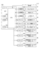
レジストレーション部50の制御構成について説明する。図8のブロック図に示すように、レジストレーション部50の動作は、画像形成装置に搭載されるコントローラ600によって制御されている。制御手段の一例であるコントローラ600は、中央処理装置(CPU)601と、記憶手段である書換え可能メモリ(RAM)602及び読取り専用メモリ(ROM)603と、外部機器又はネットワークに対するインターフェース(I/O)604を備える。
The control configuration of the
CPU601は、ユーザインタフェースである操作部412を介して入力された情報や、上述のプレレジセンサS1、斜送センサS2、及びレジ前センサS3からAD変換部605を介して入力される検知信号に基づいて制御を行う。CPU601は、ROM603等に格納されたプログラムを読出して実行し、ドライバ606,607,608,609,610を介してレジストレーション部50のアクチュエータであるモータ群(Ms,Mp,Mr,Mk)を駆動制御する。これにより、下記の制御方法の各工程を実行可能に構成されている。なお、斜送加圧モータMkは、いずれも前側及び奥側の斜送ローラに対応する数(n)で配置され、CPU601は各斜送ローラに対する従動ローラの加圧の有無及び加圧力の大きさを独立に制御可能である。
The
(レジストレーション部の制御方法)
以下、レジストレーション部50におけるシート搬送動作の制御方法と、シート搬送動作におけるシートの挙動について、図10〜図13を適宜参照しながら図9のフローチャートに沿って説明する。なお、図11〜図13において破線で示されたローラは解除状態であることを表し、実線で示されたローラは加圧状態であることを表す。また、以下のフローチャートの実行中、各斜送ローラは継続的に回転駆動されているものとする。
(Control method of registration unit)
Hereinafter, the control method of the sheet transfer operation in the
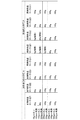
操作部412を介して画像形成の対象であるシートの坪量、サイズ、枚数等の情報が入力された状態で画像形成ジョブが開始(S101)されると、前側斜送ユニット32及び奥側斜送ユニット31の斜送圧が決定される(S102)。ただし、斜送圧とは、各斜送ローラに対する従動ローラ330の加圧力であり、ROM603等に予め格納されたテーブルに基づいて、各斜送ローラ311,321〜323について決定される。斜送圧の大きさは、図10に示すように、シートの種類に関わらす安定して搬送可能となるように、シートの坪量に応じて設定されている(突き当て時の加圧力の欄参照)。そして、決定された斜送圧に基づいて、まず奥側の斜送ローラ311の加圧が開始されて加圧状態となる(S103)。
When the image formation job is started (S101) with information such as the basis weight, size, and number of sheets of the sheet to be image-formed input via the
その後、画像形成部PY〜PKによる画像形成動作が開始(S104)されると、画像形成動作の開始タイミングを基準に、給送開始のディレイ時間がカウント(S105)された後、給送カセット51からシートが給送される(S106)。そして、プレレジ搬送部20に受け渡されたシートがプレレジセンサS1によって検知(S107)されると、停止ディレイ時間がカウント(S108)された後に、プレレジ駆動モータMpが停止される(S109)。なお、給送開始から所定時間経過してもプレレジセンサS1がシートを検知しない場合、シート詰まりを表す画面が操作部に表示され(S126)、ジョブの実行が終了する。
After that, when the image forming operation by the image forming units PY to PK is started (S104), the delay time of the feeding start is counted (S105) based on the start timing of the image forming operation, and then the feeding
この後、画像形成動作の進捗に合わせてリスタートのディレイ時間がカウント(S110)され、プレレジ駆動モータMpの駆動が再開される(S111)。プレレジ駆動モータMpの駆動再開タイミングが画像形成動作に合わせて調節されることから、シートがプレレジセンサS1に到達するまでの時間のばらつきが吸収される。その後、プレレジ搬送部20の搬送ローラ対21の加圧を解除するディレイ時間がカウント(S112)され、従動ローラ24が駆動ローラ23から離間して搬送ローラ対21が離間状態となる(S113)。これにより、シートを基準部材300に突き当てて斜行を補正する突き当て整合動作が開始される。本実施例における突き当て整合動作は、搬送ローラ対21の加圧解除から、斜送ユニット31,32がいずれも解除状態となるまでの期間(S113〜S122)である。
After that, the restart delay time is counted (S110) according to the progress of the image forming operation, and the drive of the pre-registration drive motor Mp is restarted (S111). Since the drive restart timing of the pre-registration drive motor Mp is adjusted according to the image forming operation, the variation in the time until the seat reaches the pre-registration sensor S1 is absorbed. After that, the delay time for releasing the pressurization of the
搬送ローラ対21の加圧が解除されると、図11(a)に示すように、シートは奥側斜送ユニット31から受ける搬送力によって、基準部材300に近付くようにシート搬送方向に対して斜めに移動を開始する。即ち、シートSは、シート搬送方向Dxに対して比較的大きく傾斜した奥側の斜送ローラ311の接線方向に沿って搬送され、基準部材300の基準面301に向かって素早く幅寄せされる。
When the pressurization of the
その後、シートの側端と基準部材300の基準面301がある程度近づいたタイミングで、決定済みの斜送圧に基づいて前側の斜送ローラ321〜323の加圧が開始される(S114)。つまり、奥側斜送ユニット31によるシートの斜送動作が開始された後、加圧機構33によって前側斜送ユニット32の加圧が開始されることで前側斜送ユニット32による斜送動作が開始される。すると、図11(b)に示すように、斜送ローラ321〜323に挟持されたシートSは基準部材300にさらに近づき、基準面301に側端が当接する。即ち、シートSは、シート搬送方向Dxに対して比較的小さく傾斜した前側の斜送ローラ321〜323の接線方向に沿って搬送され、幅方向Dyの移動速度が減速された状態で基準面301に当接する。これにより、シートSの側端が基準面301に衝突する際にシートSが受ける力が緩和され、シートSの座屈が防がれる。
After that, when the side edge of the sheet and the
なお、実際のシートの移動方向は、シートの慣性やシートに対する搬送抵抗等の影響により斜送ローラのスリップが生じることから、斜送ローラの接線方向とは必ずしも一致しない。しかしながら、奥側斜送ユニット31がシートに付与する搬送力の方向のシート搬送方向に対する傾斜角度を、前側斜送ユニット32に比べて大きく設定することにより、シートSの座屈を防ぎつつシートSの幅寄せを素早く行うことができる点は変わらない。
It should be noted that the actual moving direction of the sheet does not necessarily match the tangential direction of the slanted roller because the slanted roller slips due to the influence of the inertia of the sheet, the transport resistance to the sheet, and the like. However, by setting the tilt angle with respect to the seat transport direction in the direction of the transport force applied to the seat by the back side
また、斜送ローラの加圧の有無を切換えることで斜送ユニット間でシートを受け渡す構成に代えて、斜送ユニット同士の位置関係によってシートの受渡しを行う構成としてもよい。例えば、シート搬送方向において奥側斜送ユニットを前側斜送ユニットより上流に配置した場合も、奥側斜送ユニットによってシートを素早く基準部材に幅寄せしつつ、前側斜送ユニットによって基準部材に対する衝突を緩和することができる。ただし、本実施例のように前側斜送ユニット32及び奥側斜送ユニット31の斜送ローラが配置される範囲が、幅方向から視て少なくとも部分的に重なるように配置することで、斜行補正部をコンパクトに構成することができる。
Further, instead of the configuration in which the sheet is delivered between the diagonal feed units by switching the presence / absence of pressurization of the diagonal feed roller, the configuration in which the sheet is delivered depending on the positional relationship between the diagonal feed units may be used. For example, even when the back diagonal feed unit is arranged upstream of the front diagonal feed unit in the sheet transport direction, the front diagonal feed unit collides with the reference member while the seat is quickly moved to the reference member by the back diagonal feed unit. Can be alleviated. However, as in the present embodiment, the range in which the diagonal feed rollers of the front
図9のフローチャートに戻って説明を続ける。前側の斜送ローラ321〜323の加圧開始後、斜送センサS2がシートの前端、つまりシート搬送方向の下流端を検知すると(S115)、斜送ローラ321〜323の加圧力を変更するためのディレイ時間がカウントされる(S116)。このディレイ時間の長さは、シートの側端が基準部材300の基準面301に当接した後に、加圧力の変更が実行されるように設定されている。本実施例では、ディレイ時間の経過後に、前側の斜送ローラ321〜323の加圧力を低減させる処理(S117)が実行される。また、減圧後の各斜送ローラの加圧力は、ROM等に格納されたテーブル(図10の加速時の加圧力の欄参照)を参照することで決定される。そして、前側斜送ユニット32及び奥側斜送ユニット31の搬送速度を増加させる処理(S118)が行われる。
The explanation will be continued by returning to the flowchart of FIG. When the diagonal feed sensor S2 detects the front end of the sheet, that is, the downstream end in the sheet transport direction (S115) after the pressurization of the
加速の完了後、かつレジ前センサS3によるシートの前端の検知前となるように設定されたタイミングで、奥側の斜送ローラ311が加圧を解除されて解除状態となる(S119)。上述したように、奥側の斜送ローラ311は前側の斜送ローラ321〜323に比べてシート搬送方向Dxに対する傾斜角度が大きく、幅方向Dyに関して基準部材300に近づけようとする力が相対的に大きくなる(V1y>V2y)。このため、図12(a)に示すように、奥側斜送ユニット31及び前側斜送ユニット32が加圧状態である期間中に、幅方向Dyにおけるユニット間領域でシートの撓み(ループ)が形成される可能性がある。ループが形成されたままでシートの前端がレジローラ7のニップ部に突入すると、ループが押し潰されてしわが発生したり、ループの解消に伴ってシートの姿勢が乱れてシートが斜行したりする可能性がある。本実施例では、図12(a)に示すように、レジローラ7にシートが突入する前に奥側斜送ユニット31が解除状態に切換わるため、このような不都合の発生が回避される。
After the acceleration is completed and at a timing set so as to be before the detection of the front end of the seat by the pre-registration sensor S3, the
レジ前センサS3がシートの前端を検知すると(S120)、前側の斜送ローラ321〜323を解除するためのディレイ時間がカウント(S121)され、斜送ローラ321〜323の加圧が解除されて解除状態となる(S122)。このディレイ時間は、シートの前端がレジローラ7のニップ部に突入した後に前側の斜送ローラ321〜323が解除状態となるように設定される。言い換えると、前側斜送ユニット32は、シート前端が第2検知手段であるレジ前センサS3の検知位置(第2検知位置)を通過した後に加圧を解除される。一方、奥側斜送ユニット31は、シート前端が第1検知手段である斜送センサS2の検知位置(第1検知位置)を通過した後であって第2検知位置を通過する前に加圧を解除されるように構成される。なお、所定時間内にレジ前センサS3がシートを検知しない場合、シート詰まりを表す画面が操作部に表示され(S126)、ジョブの実行が終了する。
When the pre-registration sensor S3 detects the front edge of the sheet (S120), the delay time for releasing the
レジローラ7にシートが受け渡されると、図13に示すように、レジローラ7がシートを搬送しながら幅方向に移動する。これにより、幅方向Dyにおけるシートの中心位置が、画像形成部PY〜PKによって形成される画像の中心位置に合わせて位置決めされる(S123)。シートが二次転写部に送られると、画像形成すべきシートの残り枚数Kを管理するカウンタにより、Kの値がデクリメントされる(S124)。残り枚数Kが0でない場合、つまり画像形成すべきシートが残っている場合(S125:NO)、以上の動作(S103〜S124)が繰返される。このとき、プレレジ搬送部20では先行するシートの後端が通過した搬送ローラ対21が順に加圧されることで、シートが連続的に搬送され、二次転写部へと供給される。残り枚数Kが0である場合(S125:YES)、画像形成動作が完了したと判断されてジョブの実行が終了する。
When the sheet is delivered to the
このように、本実施例では、シート搬送方向Dxに対する傾斜角度が相対的に大きい斜送ローラ311を有する奥側斜送ユニット31と、傾斜角度が相対的に小さい斜送ローラ321〜323を有する前側斜送ユニット32とを併用している。言い換えると、シートを基準部材の当接面に接近させる第1方向の力を付与する第1斜送手段と、第1方向に比べてシート搬送方向に対する角度が小さい第2方向の力を付与する第2斜送手段とが設けられている。第1斜送手段によってシートが当接面に短い距離で幅寄せされることから、シート搬送装置の大型化及び複雑化を抑制することができる。また、第2斜送手段によってシートが減速されるため、シートの座屈を防ぐことができる。
As described above, in this embodiment, the back side
なお、奥側の斜送ローラの傾斜角度θ1を大きくすると、より短い搬送距離でシートの幅寄せを行うことが可能となる一方で、前側の斜送ローラの傾斜角度θ2との差が大きくなり、前側と奥側の斜送ローラ間にシートのループが生じ易くなる。また、傾斜角度θ1が大きい程、プレレジ搬送部によるシート搬送方向との差が大きくなり、受渡し時にシートが擦れてシートにダメージが生じる可能性がある。このような理由により、傾斜角度θ1は、20度以上40度以下の範囲が好ましく、25度以上35度以下とするとより好ましい。また、前側の斜送ローラの傾斜角度θ2は、奥側の斜送ローラによって幅寄せされるシートを幅方向に関して十分減速できる程度に小さいことが好ましい。このような理由により、例えば傾斜角度θ2をθ1の2分の1以下と設定すると好ましく、一例として、θ1=30°,θ2=10°とすると好適である。 If the tilt angle θ1 of the diagonal feed roller on the back side is increased, the width of the sheet can be adjusted in a shorter transport distance, but the difference from the tilt angle θ2 of the diagonal feed roller on the front side becomes large. , Sheet loops are likely to occur between the front and back diagonal feed rollers. Further, the larger the inclination angle θ1, the larger the difference from the sheet transport direction by the pre-registration transport section, and the sheet may be rubbed during delivery, causing damage to the sheet. For this reason, the inclination angle θ1 is preferably in the range of 20 degrees or more and 40 degrees or less, and more preferably 25 degrees or more and 35 degrees or less. Further, it is preferable that the inclination angle θ2 of the diagonal feed roller on the front side is small enough to sufficiently decelerate the sheet width-aligned by the diagonal feed roller on the back side in the width direction. For this reason, for example, it is preferable to set the inclination angle θ2 to 1/2 or less of θ1, and as an example, it is preferable to set θ1 = 30 ° and θ2 = 10 °.
(搬送速度の設定)
ここで、斜行補正部30におけるシートの搬送速度の設定について詳述する。図14を参照して、以下、各斜送ローラ311,321〜323について、シートSとの接触部における周速を、シートの実際の搬送速度と区別して斜送ローラの斜送速度V1,V2とする。また、斜送速度V1,V2のシート搬送方向Dxの成分をV1x,V2xとし、幅方向Dyの成分をV1y,V2yとする。なお、本実施例では、前側斜送ユニット32の各斜送ローラ321〜323について、斜送速度V2の大きさ及び方向が等しく設定されている。
(Set transport speed)
Here, the setting of the sheet transport speed in the
本実施例において、前側及び奥側の斜送ローラ311,321〜323の斜送速度V1,V2は、シート搬送方向Dxの成分が等しくなるように設定される(V1x≒V2x、図14(a)参照)。仮に、前側及び奥側の斜送ユニット間でシート搬送方向Dxの速度が均衡していない場合(V1x>V2x又はV1x<V2x、図14(b)、(c)参照)、シートSを旋回させようとする力が発生する。即ち、シート搬送方向Dxの速度が大きい方の斜送ユニットに近いシートSの側端が、他方の側端に比べてシート搬送方向Dxの下流に進むような力がシートSに作用する。そこで、本実施例では、少なくとも前側及び奥側の両方の斜送ローラが加圧状態である間(S114〜S119)、シート搬送方向Dxの成分が略一致するように斜送速度V1,V2が設定されている。これにより、斜送ローラのシート搬送方向Dxの速度差に起因するシートSの旋回を防止し、シートSの斜行補正を高い精度で行うことが可能となる。
In this embodiment, the diagonal feed speeds V1 and V2 of the
ところで、奥側の斜送ローラ311がシートに付与する力の方向は前側の斜送ローラ321〜323に比べてシート搬送方向Dxに対して大きく傾いている。このため、奥側の斜送ローラ311による斜送速度V1のシート搬送方向の成分V1xを前側の斜送ローラ321〜323に等しく設定した場合、幅方向の成分V1yは前側の斜送ローラ321〜323に比べて大きくなる。(V1x≒V2xのとき、V1y>V2y)。このことは、搬送ローラ対21の加圧が解除(S113)されてから前側斜送ユニット32の加圧が開始(S114)されるまでの間に、奥側斜送ユニット31がシートSを素早く基準部材300に幅寄せする上でも好都合である(図11(a)参照)。一方、前側の斜送ローラ321〜323が加圧されると、奥側の斜送ローラ311に比べて幅方向の速度成分が小さい前側の斜送ローラ321〜323によって幅方向の移動速度が抑制されることになる。このことは、シートSと基準部材300の基準面301との衝突を緩和する上で好都合である。
By the way, the direction of the force applied to the seat by the
(斜行補正後の旋回抑制)
次に、斜送ローラの加速処理(S118)及び加速処理に先立つ前側斜送ユニット32の減圧処理(S117)について詳しく説明する。一般に、シートの搬送速度が大きい程画像形成装置の生産性が高まるが、一方で、搬送速度が大きい程シートが基準部材に当接する際の衝撃が大きくなり、シートの座屈が生じる懸念が大きくなる。本実施例では、シートが基準部材300に当接するまでは比較的遅い速度で前側斜送ユニット32の斜送ローラ321〜323を回転駆動し、当接後に斜送ローラ321〜323の駆動速度を増加させている。
(Spinning suppression after skew correction)
Next, the acceleration process (S118) of the diagonal feed roller and the depressurization process (S117) of the front
言い換えると、第2斜送手段によってシートを当接面に当接させる動作(第1動作)の後に、シートの搬送速度を増加させる動作(第2動作)が実行される。第1動作における第1斜送手段、第2斜送手段の駆動速度を第1の速度、第2の速度とした場合、第2動作において第1斜送手段、第2斜送手段が第1の速度より大きい第3の速度、第2の速度より大きい第4の速度で駆動される。これにより、当接時にシートに加わる衝撃を低減すると共に、生産性を確保することができる。また、第1斜送手段及び第2斜送手段の斜送速度が共に加速されることから、いずれか一方のみを加速する場合に比べてシートの旋回が生じにくい。なお、加速後の斜送速度V1,V2についても、シート搬送方向の成分が等しくなるように(V1x≒V2x)設定することが好ましい。 In other words, after the operation of bringing the sheet into contact with the contact surface by the second oblique feeding means (first operation), an operation of increasing the transport speed of the sheet (second operation) is executed. When the drive speeds of the first diagonal feed means and the second diagonal feed means in the first operation are the first speed and the second speed, the first diagonal feed means and the second diagonal feed means are the first in the second operation. It is driven at a third speed higher than the speed of, and a fourth speed higher than the second speed. As a result, the impact applied to the sheet at the time of contact can be reduced, and productivity can be ensured. Further, since the diagonal feeding speeds of the first diagonal feeding means and the second diagonal feeding means are both accelerated, the seat is less likely to turn than when only one of them is accelerated. It is also preferable to set the oblique feed speeds V1 and V2 after acceleration so that the components in the sheet transport direction are equal (V1x≈V2x).
しかしながら、加速処理を行う場合、基準部材に当接することで斜行を補正されたシートの姿勢が再度乱されないように注意する必要がある。斜送ローラの加速によって質量mのシートが加速度aで加速する場合、シートには加速前の状態に比べてF=m×aの力(以下、加速力Fとする)が作用していることになる。このとき、加速力Fに起因してシートを旋回させようとするモーメントM(M=F×X、X:加速力Fによって生じるモーメントの腕の長さ)が生じ、シートの姿勢が乱される場合がある。 However, when accelerating, care must be taken not to disturb the posture of the seat whose skew has been corrected by abutting on the reference member. When the sheet with mass m accelerates with acceleration a due to the acceleration of the diagonal feed roller, a force of F = m × a (hereinafter referred to as acceleration force F) is acting on the sheet as compared with the state before acceleration. become. At this time, a moment M (M = F × X, X: the length of the arm of the moment generated by the acceleration force F) that tries to turn the seat due to the acceleration force F is generated, and the posture of the seat is disturbed. In some cases.
この現象によるシートの挙動は、加速力Fの作用点及び加速力Fの方向と、モーメントの中心との関係によって定まる。加速力Fの作用点とは、各斜送ローラ311,321〜323とシートの接触位置である。加速力Fの方向とは、シートとの接触位置における各斜送ローラの回転方向である。モーメントの中心とは、シートに対する搬送抵抗をシートの第1面及び第2面について面積分した場合にそれが釣り合う位置であり、シートの見かけ上の重心位置である。シートに対する搬送抵抗が一様であるとした場合、モーメントの中心はシートの重心位置と一致する。実際には、搬送ローラ対と搬送ガイドとの間のシートに対する摩擦係数の差やシート搬送路の湾曲等の要因により、モーメントの中心はシートの重心位置に必ずしも一致しない。実験的には、例えば、1つだけ配置した斜送ローラの角度及び位置の条件を変更しつつ、シートを加速した場合のシートの旋回方向を観測することで、モーメントの中心を推定することができる。
The behavior of the seat due to this phenomenon is determined by the relationship between the point of action of the accelerating force F, the direction of the accelerating force F, and the center of the moment. The point of action of the accelerating force F is the contact position between the
以下、図15の点“O”をモーメントの中心として、加速処理におけるシートの挙動を安定させるための構成について説明する。図15(a)、(b)は参考例の斜行補正部を示す模式図であり、図15(c)に示す本実施例の斜行補正部30とは斜送ローラの配置が異なる。
Hereinafter, a configuration for stabilizing the behavior of the sheet in the acceleration process will be described with the point “O” in FIG. 15 as the center of the moment. 15 (a) and 15 (b) are schematic views showing the skew correction unit of the reference example, and the arrangement of the diagonal feed rollers is different from that of the
前側斜送ユニット32及び奥側斜送ユニット31の加速によってシートSにモーメントM1,M2が作用する場合、次の3通りの状況を想定することができる。
(A)前側/奥側の斜送ローラが共に図中時計回り方向(CW)のモーメントを発生させる(図15(a))。
(B)前側/奥側の斜送ローラが共に図中半時計回り方向(CCW)のモーメントを発生させる(図15(b))。
(C)前側の斜送ローラが図中時計回り方向(CW)のモーメントを発生させ、奥側の斜送ローラが図中反時計回り方向(CCW)のモーメントを発生させる(図15(c))。
When the moments M1 and M2 act on the seat S due to the acceleration of the front
(A) The diagonal feed rollers on the front side and the back side both generate a moment in the clockwise direction (CW) in the figure (FIG. 15 (a)).
(B) The diagonal feed rollers on the front side and the back side both generate a moment in the counterclockwise direction (CCW) in the figure (FIG. 15 (b)).
(C) The diagonal feed roller on the front side generates a moment in the clockwise direction (CW) in the figure, and the diagonal feed roller on the back side generates a moment in the counterclockwise direction (CCW) in the figure (FIG. 15 (c)). ).
(A)の場合、図中時計回り方向のモーメントM1,M2により、加速処理に伴ってシートSは前端が基準部材300から離れる方向に旋回する挙動を示す。(B)の場合、図中反時計回り方向のモーメントM1,M2により、加速処理に伴ってシートSは後端が基準部材300から離れる方向に旋回する挙動を示す。(A)及び(B)のいずれの場合も、前側及び奥側の斜送ユニット31,32の加速に起因するモーメントが加算的に作用し、シートの旋回が生じやすくなる。
In the case of (A), the seat S exhibits a behavior in which the front end of the seat S turns away from the
一方、(C)の場合、前側斜送ユニット32及び奥側斜送ユニット31の加速は逆方向のモーメントを発生させる。この場合、前側及び奥側の斜送ローラの加速に起因するモーメントが互いに打ち消し合うように働くため、シートの旋回が生じにくく、加速時のシートの姿勢を安定させることができる。本実施例では、(C)のような構成、つまりシートが基準部材300に当接してからレジローラ7に到達するまでのモーメントの中心Oに対して、前側斜送ユニット32及び奥側斜送ユニット31が幅方向の一方側と他方側に位置するような配置が採用される。具体的には、前側斜送ユニット32を搬送中心L0(図2参照)の一方側に配置し、奥側斜送ユニット31を搬送中心L0の他方側に配置する。これにより、各斜送ユニット31,32によって派生するモーメントが互いに打ち消し合い、シートの挙動が安定する。
On the other hand, in the case of (C), the acceleration of the front
これに加えて、本実施例では加速時のシートの姿勢をさらに安定させるため、加速時に前側斜送ユニット32がシートを挟持する力を低減する処理(図9のS117、及び図10参照)を行っている。このような処理を行う1つの理由として斜送ローラの数の違いが挙げられ、他の理由としてモーメントの腕の長さの違いが挙げられる。
In addition to this, in this embodiment, in order to further stabilize the posture of the seat during acceleration, a process of reducing the force with which the front
斜送ローラの数の違いについて、前側斜送ユニット32が3つの斜送ローラ321〜323を有する一方、奥側斜送ユニット31は1つの斜送ローラ311によって構成される。このため、全ての斜送ローラがシートに接触している状態では、加速時に前側斜送ユニット32によって発生するモーメントM2が、奥側斜送ユニット31によって発生するモーメントをM1に比べて大きくなり易い。この場合、図15(c)においてシートSが時計回り方向に旋回する可能性がある。
Regarding the difference in the number of diagonal feed rollers, the front
また、モーメントの腕の長さについて、基準部材300に当接してからレジローラ7に到達するまでのモーメントの中心Oは、本実施例の場合、搬送中心L0の付近、かつプレレジ搬送部20と斜行補正部30の境界付近(図2参照)に位置する。このような場合、モーメントの中心Oがシート搬送方向のより上流位置にある場合に比べて、前側の斜送ローラ321〜323によるモーメントの腕の長さX21,X22,X23は短く、奥側の斜送ローラ311によるモーメントの腕の長さX1は長くなる。したがって、斜送ユニット31,32の加速によって各斜送ローラがシートに付与する搬送力が大きくなった場合、前側斜送ユニット32によるモーメントM2の増加分が奥側斜送ユニット31によるモーメントM1の増加分より大きくなり易い。
Further, regarding the length of the arm of the moment, the center O of the moment from the contact with the
このような知見から、本実施例では、加速処理を行う前に前側斜送ユニット32の加圧力を低減させている(図9のS117)。言い換えると、シートを当接面に当接させる第1動作(S114)の後にシートの搬送速度を加速させる第2動作(S118)が行われる場合において、第2動作における第2斜送手段の加圧力が第1動作に比べて低く設定されている。これにより、突き当て整合動作の後半、つまりシートが基準部材300に当接した後の状態において各斜送ユニット31,32によって生じるモーメントM1,M2が均衡し(M1≒M2)、シートの旋回が生じにくくなる。
Based on these findings, in this embodiment, the pressing force of the front
なお、前側斜送ユニット32の加圧力を低減する方法としては、次の(1)〜(3)が挙げられる。
(1)3つある斜送ローラの加圧力をそれぞれ弱くする方法
(2)3つある斜送ローラのうちの1つ又は2つの加圧を解除する方法
(3)3つある斜送ローラのうちの1つ又は2つの加圧を解除し、残りの斜送ローラの加圧力をそれぞれ弱くする方法
Examples of the method for reducing the pressing force of the front
(1) A method of weakening the pressing force of each of the three diagonal feed rollers (2) A method of releasing the pressurization of one or two of the three diagonal feed rollers (3) Of the three diagonal feed rollers A method of releasing the pressurization of one or two of them and weakening the pressurization of the remaining diagonal feed rollers.
本実施例では、図10の“加速時の加圧力”の欄に示すように、シートの種類に応じて(1)〜(3)の方法のいずれかを実行する。これにより、シートの種類に関わらず、シートの旋回を防いで安定して搬送可能なニップ圧に設定される。 In this embodiment, as shown in the column of "pressurization during acceleration" in FIG. 10, one of the methods (1) to (3) is executed depending on the type of sheet. As a result, regardless of the type of seat, the nip pressure is set so that the seat can be stably conveyed by preventing the seat from turning.
次に、実施例2に係るシート搬送装置について図16を用いて説明する。本実施例におけるシート搬送装置のレジストレーション部は、シート搬送動作において奥側斜送ユニットの加圧を開始するタイミングが上記実施例1と異なっている。その他の構成は実施例1と同様であるため、共通する要素には実施例1と同符号を付して説明を省略する。以下、本実施例におけるシート搬送動作の制御方法について、図16のフローチャートに沿って説明する。 Next, the sheet transport device according to the second embodiment will be described with reference to FIG. In the registration section of the sheet transport device in this embodiment, the timing at which the pressurization of the back diagonal feed unit is started in the sheet transport operation is different from that in the first embodiment. Since other configurations are the same as those in the first embodiment, the common elements are designated by the same reference numerals as those in the first embodiment, and the description thereof will be omitted. Hereinafter, the control method of the sheet transport operation in this embodiment will be described with reference to the flowchart of FIG.
操作部412を介して画像形成の対象であるシートの坪量、サイズ、枚数等の情報が入力された状態で画像形成ジョブが開始(S201)されると、前側斜送ユニット32及び奥側斜送ユニット31の斜送圧が決定される(S202)。実施例1と異なり、奥側斜送ユニット31の加圧はこの段階では開始されない。
When the image formation job is started (S201) with information such as the basis weight, size, and number of sheets of the sheet to be image-formed input via the
その後、画像形成部PY〜PKによる画像形成動作が開始(S203)されると、画像形成動作の開始タイミングを基準に、給送開始のディレイ時間がカウント(S204)された後、給送カセット51からシートが給送される(S205)。そして、プレレジ搬送部20に受け渡されたシートがプレレジセンサS1によって検知(S206)されると、停止ディレイ時間がカウント(S207)された後に、プレレジ駆動モータMpが停止される(S208)。なお、給送開始から所定時間経過してもプレレジセンサS1がシートを検知しない場合、シート詰まりを表す画面が操作部に表示され(S226)、ジョブの実行が終了する。
After that, when the image forming operation by the image forming units PY to PK is started (S203), the delay time of the feeding start is counted (S204) based on the start timing of the image forming operation, and then the feeding
この後、画像形成動作の進捗に合わせて奥側斜送ユニット31の加圧を開始するためのディレイ時間がカウント(S209)され、奥側斜送ユニット31の斜送ローラ311が決定済みの斜送圧に基づいて加圧される(S210)。その後、停止しているプレレジ駆動モータMpの駆動が再開される(S211)。そして、プレレジ搬送部20の搬送ローラ対21の加圧を解除するディレイ時間がカウント(S212)され、従動ローラ24が駆動ローラ23から離間して搬送ローラ対21が離間状態となる(S213)。
After that, the delay time for starting the pressurization of the back side
実施例1では、奥側斜送ユニット31が予め加圧されている状態でプレレジ搬送部20から斜行補正部30にシートが送り込まれる。一方、本実施例では、奥側斜送ユニット31の加圧開始を遅らせて、プレレジ搬送部20の搬送ローラ対21と奥側の斜送ローラ311とが同時に加圧状態である期間(S210〜S212)が可能な限り短くなるようにしている。これにより、斜送ローラ311とシートの摺擦によるローラ表面のゴムの劣化及びシートのダメージを低減することができる。また、本実施例においても、結果としてプレレジ駆動モータMpの駆動再開タイミングが画像形成動作に合わせて調節されることから、シートがプレレジセンサS1に到達するまでの時間のばらつきが吸収される。
In the first embodiment, the sheet is fed from the
なお、プレレジ駆動モータMpの駆動再開後に奥側斜送ユニット31の加圧を開始する構成としてもよい。また、プレレジ搬送部20から斜行補正部30にシートを確実に受け渡すため、奥側斜送ユニット31の加圧開始後に搬送ローラ対21が離間することが好ましい。
In addition, the pressurization of the back side
搬送ローラ対21の加圧が解除(S213)されると、斜行補正部30による突き当て整合動作が開始される。即ち、奥側斜送ユニット31によってシートの斜送が開始され、基準部材300の基準面301に向かってシートが幅寄せされる。その後、シートの側端と基準部材300の基準面301がある程度近づいたタイミングで、決定済みの斜送圧に基づいて前側の斜送ローラ321〜323の加圧が開始される(S214)。すると、シートは基準部材300にさらに近づき、基準面301に側端が当接することで斜行を補正される。
When the pressurization of the
このように、本実施例においても、第1斜送手段としての奥側斜送ユニット31と、第2斜送手段としての前側斜送ユニット32とを併用している。これにより、基準部材300に対するシートの衝突を緩和してシートの座屈を防ぎつつ、シートの幅寄せを素早く行うことで装置の小型化・簡素化に貢献することができる。
As described above, also in this embodiment, the back side
前側の斜送ローラ321〜323の加圧開始後、斜送センサS2がシートの前端を検知すると(S215)、斜送ローラ321〜323の加圧力を変更するためのディレイ時間がカウントされる(S216)。そして、ディレイ時間の経過後に、前側の斜送ローラ321〜323の加圧力を低減させる処理(S217)が実行された後、前側斜送ユニット32及び奥側斜送ユニット31の搬送速度を増加させる処理(S218)が行われる。
When the diagonal feed sensor S2 detects the front edge of the sheet (S215) after the pressurization of the
加速の完了後、かつレジ前センサS3によるシートの前端の検知前となるように設定されたタイミングで、奥側の斜送ローラ311が加圧を解除されて解除状態となる(S219)。これにより、レジローラ7にシートが突入する前にシートのループが解消される。レジ前センサS3がシートの前端を検知すると(S220)、前側の斜送ローラ321〜323を解除するためのディレイ時間がカウント(S221)され、斜送ローラ321〜323の加圧が解除されて解除状態となる(S222)。このディレイ時間は、シートの前端がレジローラ7のニップ部に突入した後に前側の斜送ローラ321〜323が解除状態となるように設定される。なお、所定時間内にレジ前センサS3がシートを検知しない場合、シート詰まりを表す画面が操作部に表示され(S226)、ジョブの実行が終了する。
After the acceleration is completed and at a timing set so as to be before the detection of the front end of the seat by the pre-registration sensor S3, the
レジローラ7にシートが受け渡されると、レジローラ7がシートを搬送しながら幅方向に移動し、幅方向におけるシートの中心位置が、画像形成部PY〜PKによって形成される画像の中心位置に合わせて位置決めされる(S223)。シートが二次転写部に送られると、画像形成すべきシートの残り枚数Kを管理するカウンタにより、Kの値がデクリメントされる(S224)。残り枚数Kが0でない場合、つまり画像形成すべきシートが残っている場合(S225:NO)、以上の動作(S203〜S224)が繰返される。残り枚数Kが0である場合(S225:YES)、画像形成動作が完了したと判断されてジョブの実行が終了する。
When the sheet is delivered to the
次に、実施例3に係るシート搬送装置について図17、図18を用いて説明する。本実施例におけるシート搬送装置のレジストレーション部は、厚紙等のシートを搬送する場合に、シートの搬送速度を加速する際のシートの旋回を防ぐ方法が上記実施例2と異なっている。その他の構成は実施例2と同様であるため、共通する要素には実施例2と同符号を付して説明を省略する。以下、本実施例におけるシート搬送動作の制御方法について、図18を適宜参照しながら図17のフローチャートに沿って説明する。 Next, the sheet transport device according to the third embodiment will be described with reference to FIGS. 17 and 18. The registration unit of the sheet transport device in this embodiment is different from the above-described 2 in the method of preventing the sheet from turning when accelerating the sheet transport speed when transporting a sheet such as thick paper. Since other configurations are the same as those in the second embodiment, the common elements are designated by the same reference numerals as those in the second embodiment and the description thereof will be omitted. Hereinafter, the control method of the sheet transport operation in this embodiment will be described with reference to FIG. 18 as appropriate with reference to the flowchart of FIG.
操作部412を介して画像形成の対象であるシートの坪量、サイズ、枚数等の情報が入力された状態で画像形成ジョブが開始(S301)されると、前側斜送ユニット32及び奥側斜送ユニット31の斜送圧が決定される(S302)。
When the image formation job is started (S301) with information such as the basis weight, size, and number of sheets of the sheet to be image-formed input via the
その後、画像形成部PY〜PKによる画像形成動作が開始(S303)されると、画像形成動作の開始タイミングを基準に、給送開始のディレイ時間がカウント(S304)された後、給送カセット51からシートが給送される(S305)。そして、プレレジ搬送部20に受け渡されたシートがプレレジセンサS1によって検知(S306)されると、停止ディレイ時間がカウント(S307)された後に、プレレジ駆動モータMpが停止される(S308)。なお、給送開始から所定時間経過してもプレレジセンサS1がシートを検知しない場合、シート詰まりを表す画面が操作部に表示され(S326)、ジョブの実行が終了する。
After that, when the image forming operation by the image forming units PY to PK is started (S303), the delay time of the feeding start is counted (S304) based on the start timing of the image forming operation, and then the feeding
この後、画像形成動作の進捗に合わせて奥側斜送ユニット31の加圧を開始するためのディレイ時間がカウント(S309)され、奥側斜送ユニット31の斜送ローラ311が決定済みの斜送圧に基づいて加圧される(S310)。その後、停止しているプレレジ駆動モータMpの駆動が再開される(S311)。そして、プレレジ搬送部20の搬送ローラ対21の加圧を解除するディレイ時間がカウント(S312)され、従動ローラ24が駆動ローラ23から離間して搬送ローラ対21が離間状態となる(S313)。
After that, the delay time for starting the pressurization of the back side
搬送ローラ対21の加圧が解除(S313)されると、斜行補正部30による突き当て整合動作が開始される。即ち、奥側斜送ユニット31によってシートの斜送が開始され、基準部材300の基準面301に向かってシートが幅寄せされる。その後、シートの側端と基準部材300の基準面301がある程度近づいたタイミングで、決定済みの斜送圧に基づいて前側の斜送ローラ321〜323の加圧が開始される(S314)。すると、シートは基準部材300にさらに近づき、基準面301に側端が当接することで斜行を補正される。
When the pressurization of the
このように、本実施例においても、第1斜送手段としての奥側斜送ユニット31と、第2斜送手段としての前側斜送ユニット32とを併用している。これにより、基準部材300に対するシートの衝突を緩和してシートの座屈を防ぎつつ、シートの幅寄せを素早く行うことで装置の小型化・簡素化に貢献することができる。
As described above, also in this embodiment, the back side
ここで、本実施例では、前側の斜送ローラ321〜323の加圧開始後、斜送センサS2がシートの前端を検知すると(S315)、奥側の斜送ローラ311の加圧力を変更するためのディレイ時間がカウントされる(S316)。そして、ディレイ時間の経過後に、奥側の斜送ローラ311の加圧力を低減させる処理(S317)が実行された後、前側斜送ユニット32及び奥側斜送ユニット31の搬送速度を増加させる処理(S318)が行われる。
Here, in this embodiment, when the diagonal feed sensor S2 detects the front end of the sheet (S315) after the pressurization of the
上述した通り、シート搬送速度を増加させる加速処理が行われる場合、前側と奥側の斜送ローラの数の違い及びシート搬送方向に対する傾斜角度の違い(モーメントの腕の長さの違い)によりシートを旋回させようとするモーメントが発生する場合がある。実施例1では、前側斜送ユニット32がシートを挟持する力を低減させることで、加速時に前側斜送ユニット32によって生じるモーメントM1を抑制し、奥側斜送ユニットによるモーメントM2と均衡させていた。
As described above, when the acceleration process to increase the sheet transfer speed is performed, the sheet is caused by the difference in the number of diagonal feed rollers on the front side and the back side and the difference in the inclination angle with respect to the sheet transfer direction (difference in the length of the arm of the moment). There may be a moment that tries to turn. In the first embodiment, by reducing the force of the front
しかしながら、例えば厚いシート等、搬送抵抗が比較的大きいシートの場合、前側の斜送ローラ321〜323の加圧力を低減すると搬送力の不足によってシートの搬送が遅滞したり搬送動作の安定性が低下したりする懸念がある。そこで、本実施例では、坪量が300gsm以上のシートを搬送する場合、前側の斜送ローラ321〜323の加圧力を低減することなく、奥側の斜送ローラ311の加圧力を増加させる(図18の最下段参照)。即ち、本実施例では、シートを当接面に当接させる第1動作(S314)の後にシートの搬送速度を加速させる第2動作(S318)が行われる場合において、第2動作における第1斜送手段の加圧力が第1動作に比べて高く設定されている。
However, in the case of a sheet having a relatively large transfer resistance, such as a thick sheet, if the pressing force of the
これにより、奥側斜送ユニット31がシートを挟持する力が大きくなり、加速時に奥側斜送ユニット31によって生じるモーメントM1が増大するため、前側斜送ユニット32によって生じるモーメントM2と均衡させることができる(図15(c)参照)。従って、搬送力の不足を防止しつつ、加速時のシートの旋回を低減して安定した斜行補正を行うことが可能となる。
As a result, the force with which the back-side
なお、図17に示すフローチャートはシートの坪量が300gsm以上である場合に実行されるものであり、坪量が300gsm未満のシートについては実施例2と同様の制御が行われる。つまり、坪量が300gsm未満のシートについては、加速処理の前に前側斜送ユニット32の加圧力を低減する処理(図16のS217)が行われる。これにより、比較的薄いシートについては奥側の斜送ローラ311がスリップしやすい条件となり、レジローラ7におけるしわや斜行の要因となる過大なループの発生を抑制することができる。このように、本実施例では、加速時の第1斜送手段の加圧力を高く設定するモードと、加速時の第2斜送手段の加圧力を低く設定するモードとをシートの坪量に応じて使い分けている。
The flowchart shown in FIG. 17 is executed when the basis weight of the sheet is 300 gsm or more, and the same control as in the second embodiment is performed for the sheet having a basis weight of less than 300 gsm. That is, for a sheet having a basis weight of less than 300 gsm, a process of reducing the pressing force of the front diagonal feed unit 32 (S217 in FIG. 16) is performed before the acceleration process. As a result, for a relatively thin sheet, the
図17のフローチャートに戻って説明を継続する。加速の完了後、かつレジ前センサS3によるシートの前端の検知前となるように設定されたタイミングで、奥側の斜送ローラ311が加圧を解除されて解除状態となる(S319)。これにより、レジローラ7にシートが突入する前にシートのループが解消される。レジ前センサS3がシートの前端を検知すると(S320)、前側の斜送ローラ321〜323を解除するためのディレイ時間がカウント(S321)され、斜送ローラ321〜323の加圧が解除されて解除状態となる(S322)。このディレイ時間は、シートの前端がレジローラ7のニップ部に突入した後に前側の斜送ローラ321〜323が解除状態となるように設定される。なお、所定時間内にレジ前センサS3がシートを検知しない場合、シート詰まりを表す画面が操作部に表示され(S326)、ジョブの実行が終了する。
The explanation will be continued by returning to the flowchart of FIG. After the acceleration is completed and at a timing set so as to be before the detection of the front end of the seat by the pre-registration sensor S3, the
レジローラ7にシートが受け渡されると、レジローラ7がシートを搬送しながら幅方向に移動し、幅方向におけるシートの中心位置が、画像形成部PY〜PKによって形成される画像の中心位置に合わせて位置決めされる(S323)。シートが二次転写部に送られると、画像形成すべきシートの残り枚数Kを管理するカウンタにより、Kの値がデクリメントされる(S324)。残り枚数Kが0でない場合、つまり画像形成すべきシートが残っている場合(S325:NO)、以上の動作(S303〜S324)が繰返される。残り枚数Kが0である場合(S325:YES)、画像形成動作が完了したと判断されてジョブの実行が終了する。
When the sheet is delivered to the
次に、実施例4に係るシート搬送装置について図19、図20を用いて説明する。本実施例におけるシート搬送装置のレジストレーション部は、非常に薄い極薄紙を含む一部のシートを搬送する場合のシート搬送動作の制御方法が上記実施例3と異なっている。その他の構成は実施例3と同様であるため、共通する要素には実施例3と同符号を付して説明を省略する。以下、本実施例におけるシート搬送動作の制御方法について、図20を適宜参照しながら図19のフローチャートに沿って説明する。 Next, the sheet transport device according to the fourth embodiment will be described with reference to FIGS. 19 and 20. The registration unit of the sheet transfer device in this embodiment is different from the above-mentioned Example 3 in the control method of the sheet transfer operation when a part of the sheets including a very thin ultrathin paper is conveyed. Since other configurations are the same as those in the third embodiment, the common elements are designated by the same reference numerals as those in the third embodiment and the description thereof will be omitted. Hereinafter, the control method of the sheet transport operation in this embodiment will be described with reference to FIG. 20 as appropriate with reference to the flowchart of FIG.
操作部412を介して画像形成の対象であるシートの坪量、サイズ、枚数等の情報が入力された状態で画像形成ジョブが開始(S401)されると、前側斜送ユニット32及び奥側斜送ユニット31の斜送圧が決定される(S402)。
When the image formation job is started (S401) with information such as the basis weight, size, and number of sheets of the sheet to be image-formed input via the
その後、画像形成部PY〜PKによる画像形成動作が開始(S403)されると、画像形成動作の開始タイミングを基準に、給送開始のディレイ時間がカウント(S404)された後、給送カセット51からシートが給送される(S405)。そして、プレレジ搬送部20に受け渡されたシートがプレレジセンサS1によって検知(S406)されると、停止ディレイ時間がカウント(S407)された後に、プレレジ駆動モータMpが停止される(S408)。なお、給送開始から所定時間経過してもプレレジセンサS1がシートを検知しない場合、シート詰まりを表す画面が操作部に表示され(S426)、ジョブの実行が終了する。
After that, when the image forming operation by the image forming units PY to PK is started (S403), the delay time of the feeding start is counted (S404) based on the start timing of the image forming operation, and then the feeding
この後、画像形成動作の進捗に合わせて奥側斜送ユニット31の加圧を開始するためのディレイ時間がカウント(S409)され、奥側斜送ユニット31の斜送ローラ311が決定済みの斜送圧に基づいて加圧される(S410)。その後、停止しているプレレジ駆動モータMpの駆動が再開される(S411)。そして、プレレジ搬送部20の搬送ローラ対21の加圧を解除するディレイ時間がカウント(S412)され、従動ローラ24が駆動ローラ23から離間して搬送ローラ対21が離間状態となる(S413)。
After that, the delay time for starting the pressurization of the back side
搬送ローラ対21の加圧が解除(S413)されると、斜行補正部30による突き当て整合動作が開始される。即ち、奥側斜送ユニット31によってシートの斜送が開始され、基準部材300の基準面301に向かってシートが幅寄せされる。その後、シートの側端と基準部材300の基準面301がある程度近づいたタイミングで、決定済みの斜送圧に基づいて前側の斜送ローラ321〜323の加圧が開始される(S414)。すると、シートは基準部材300にさらに近づき、基準面301に側端が当接することで斜行を補正される。
When the pressurization of the
このように、本実施例においても、第1斜送手段としての奥側斜送ユニット31と、第2斜送手段としての前側斜送ユニット32とを併用している。これにより、基準部材300に対するシートの衝突を緩和してシートの座屈を防ぎつつ、シートの幅寄せを素早く行うことで装置の小型化・簡素化に貢献することができる。
As described above, also in this embodiment, the back side
ここで、本実施例では、前側の斜送ローラ321〜323の加圧開始後、斜送センサS2がシートの前端を検知すると(S415)、奥側斜送ユニット31の加圧を解除するためのディレイ時間がカウントされる(S416)。そして、ディレイ時間の経過後に、奥側の斜送ローラ311の加圧を解除する処理(S417)が実行された後、前側斜送ユニット32及び奥側斜送ユニット31の搬送速度を増加させる処理(S418)が行われる。
Here, in this embodiment, when the diagonal feed sensor S2 detects the front end of the sheet (S415) after the pressurization of the front
坪量が40gsm以上60gsm未満の極薄紙等、搬送抵抗が小さいシートの場合には、シート搬送速度を加速してもシートの旋回が生じにくい一方で、斜送ユニット31,32の斜送方向の差によってシートのループが生じる懸念がある。即ち、シート搬送方向に対する傾斜角度の大きい奥側の斜送ローラ311によってシートが基準部材300に向かって引き寄せられ、前側及び奥側の斜送ユニット31,32の間にシートのループが生じやすい。
In the case of a sheet with a small transfer resistance, such as ultra-thin paper with a basis weight of 40 gsm or more and less than 60 gsm, the sheet is less likely to rotate even if the sheet transfer speed is accelerated, but in the oblique feed direction of the
本実施例では、シートの前端が斜送センサS2によって検知されてから、加速処理(S418)の前に奥側斜送ユニット31の加圧が解除される(S417)。このため、シートの前端がレジローラ7に到達する前にループが解消され、しわや斜行の発生を低減することができる。
In this embodiment, after the front edge of the sheet is detected by the diagonal feed sensor S2, the pressurization of the back
一方、坪量が60gsm以上のシートは、比較的搬送抵抗が大きいため、シート搬送速度を加速させる際のシートの旋回を低減することが好ましい。図19に示すフローチャートがシートの坪量が40gsm以上60gsm未満である場合に実行されるものであり、坪量が60gsm未満のシートについては実施例3と同様の制御が行われる。つまり、坪量が60gsm以上300gsm未満のシートについては、加速前に前側斜送ユニット32の加圧力を低減する処理(図20参照)が行われる。また、坪量が300gsm以上のシートについては、加速前に奥側斜送ユニット31の加圧力を増加させる処理が行われる(図20参照)。
On the other hand, since a sheet having a basis weight of 60 gsm or more has a relatively large transfer resistance, it is preferable to reduce the turning of the sheet when accelerating the sheet transfer speed. The flowchart shown in FIG. 19 is executed when the basis weight of the sheet is 40 gsm or more and less than 60 gsm, and the same control as in the third embodiment is performed for the sheet having the basis weight of less than 60 gsm. That is, for a sheet having a basis weight of 60 gsm or more and less than 300 gsm, a process of reducing the pressing force of the front
即ち、本実施例では、シートの坪量に応じて第1モードと第2モードとを切換え、第1の坪量を有するシートに対して第1モードのシート搬送動作を実行し、第1の坪量より小さい第2の坪量を有するシートに対して第2モードのシート搬送動作を実行する。ただし、第1モードとは、前側斜送ユニット32によるシートの斜送動作(第1動作)を開始した後も奥側斜送ユニット31を加圧状態に保持したままで加速動作(第2動作)を開始するモードである。また、第2モードとは、前側斜送ユニット32によるシートの斜送動作(第1動作)を開始した後に奥側斜送ユニット31を解除状態に切換えて加速動作(第2動作)を開始するモードである。
That is, in this embodiment, the first mode and the second mode are switched according to the basis weight of the sheet, the sheet transfer operation of the first mode is executed for the sheet having the first basis weight, and the first mode is executed. The sheet transfer operation of the second mode is executed for the sheet having the second basis weight smaller than the basis weight. However, in the first mode, even after the seat diagonal feed operation (first operation) by the front
図19のフローチャートに戻って説明を継続する。レジ前センサS3がシートの前端を検知すると(S419)、前側の斜送ローラ321〜323を解除するためのディレイ時間がカウント(S420)され、斜送ローラ321〜323の加圧が解除されて解除状態となる(S421)。このディレイ時間は、シートの前端がレジローラ7のニップ部に突入した後に前側の斜送ローラ321〜323が解除状態となるように設定される。なお、所定時間内にレジ前センサS3がシートを検知しない場合、シート詰まりを表す画面が操作部に表示され(S425)、ジョブの実行が終了する。
The explanation will be continued by returning to the flowchart of FIG. When the pre-registration sensor S3 detects the front edge of the sheet (S419), the delay time for releasing the
レジローラ7にシートが受け渡されると、レジローラ7がシートを搬送しながら幅方向に移動し、幅方向におけるシートの中心位置が、画像形成部PY〜PKによって形成される画像の中心位置に合わせて位置決めされる(S422)。シートが二次転写部に送られると、画像形成すべきシートの残り枚数Kを管理するカウンタにより、Kの値がデクリメントされる(S423)。残り枚数Kが0でない場合、つまり画像形成すべきシートが残っている場合(S424:NO)、以上の動作(S403〜S423)が繰返される。残り枚数Kが0である場合(S424:YES)、画像形成動作が完了したと判断されてジョブの実行が終了する。
When the sheet is delivered to the
次に、実施例5に係るシート搬送装置について図21〜23を用いて説明する。本実施例におけるシート搬送装置のレジストレーション部は、奥側斜送ユニットが複数の斜送ローラを有する点が上記実施例1と異なっている。その他の構成は実施例1と同様であるため、共通する要素には実施例1と同符号を付して説明を省略する。 Next, the sheet transport device according to the fifth embodiment will be described with reference to FIGS. 21 to 23. The registration unit of the sheet transport device in this embodiment is different from the first embodiment in that the back-side oblique feed unit has a plurality of oblique feed rollers. Since other configurations are the same as those in the first embodiment, the common elements are designated by the same reference numerals as those in the first embodiment, and the description thereof will be omitted.
図21に示すように、本実施例における斜行補正部30には、3つの斜送ローラ311,312,313を有する奥側斜送ユニット31が配置されている。各斜送ローラ311〜313は、シート搬送方向Dxの下流に向かう程、幅方向Dyにおいて基準部材300に近付くように傾斜した方向に沿って互いに平行に配置されている。実施例1と同様に、奥側の斜送ローラ311〜313は、シートに付与する搬送力の方向が前側の斜送ローラ321〜323に比べてシート搬送方向Dxに対する角度が大きくなるように(θ1>θ2)配置されている。
As shown in FIG. 21, in the
奥側斜送ユニット31の各斜送ローラ311〜313には従動ローラが対向しており、各従動ローラは図6、図7に示すものと同様の加圧機構33によって加圧状態と解除状態とを切換可能に構成されている。以下、本実施例におけるシート搬送動作の制御方法について、図23を適宜参照して図22のフローチャートに沿って説明する。
A driven roller faces each of the
操作部412を介して画像形成の対象であるシートの坪量、サイズ、枚数等の情報が入力された状態で画像形成ジョブが開始(S501)されると、前側斜送ユニット32及び奥側斜送ユニット31の斜送圧が決定される(S502)。そして、決定された斜送圧に基づいて、まず奥側の斜送ローラ311〜313の加圧が開始されて加圧状態となる(S503)。斜送圧の大きさは、図23の表に示すように、シートの種類に関わらす安定して搬送可能となるように、シートの坪量に応じて設定されている。
When the image formation job is started (S501) with information such as the basis weight, size, and number of sheets of the sheet to be image-formed input via the
その後、画像形成部PY〜PKによる画像形成動作が開始(S504)されると、画像形成動作の開始タイミングを基準に、給送開始のディレイ時間がカウント(S505)された後、給送カセット51からシートが給送される(S506)。そして、プレレジ搬送部20に受け渡されたシートがプレレジセンサS1によって検知(S507)されると、停止ディレイ時間がカウント(S508)された後に、プレレジ駆動モータMpが停止される(S509)。なお、給送開始から所定時間経過してもプレレジセンサS1がシートを検知しない場合、シート詰まりを表す画面が操作部に表示され(S525)、ジョブの実行が終了する。
After that, when the image forming operation by the image forming units PY to PK is started (S504), the delay time of the feeding start is counted (S505) based on the start timing of the image forming operation, and then the feeding
この後、画像形成動作の進捗に合わせてリスタートのディレイ時間がカウント(S510)され、プレレジ駆動モータMpの駆動が再開される(S511)。プレレジ駆動モータMpの駆動再開タイミングが画像形成動作に合わせて調節されることから、シートがプレレジセンサS1に到達するまでの時間のばらつきが吸収される。その後、プレレジ搬送部20の搬送ローラ対21の加圧を解除するディレイ時間がカウント(S512)され、従動ローラ24が駆動ローラ23から離間して搬送ローラ対21が離間状態となる(S513)。
After that, the restart delay time is counted (S510) according to the progress of the image forming operation, and the drive of the pre-registration drive motor Mp is restarted (S511). Since the drive restart timing of the pre-registration drive motor Mp is adjusted according to the image forming operation, the variation in the time until the seat reaches the pre-registration sensor S1 is absorbed. After that, the delay time for releasing the pressurization of the
搬送ローラ対21の加圧が解除(S513)されると、斜行補正部30による突き当て整合動作が開始される。即ち、奥側斜送ユニット31によってシートの斜送が開始され、基準部材300の基準面301に向かってシートが幅寄せされる。その後、シートの側端と基準部材300の基準面301がある程度近づいたタイミングで、決定済みの斜送圧に基づいて前側の斜送ローラ321〜323の加圧が開始される(S514)。すると、シートは基準部材300にさらに近づき、基準面301に側端が当接することで斜行を補正される。
When the pressurization of the
このように、本実施例においても、第1斜送手段としての奥側斜送ユニット31と、第2斜送手段としての前側斜送ユニット32とを併用している。これにより、基準部材300に対するシートの衝突を緩和してシートの座屈を防ぎつつ、シートの幅寄せを素早く行うことで装置の小型化・簡素化に貢献することができる。
As described above, also in this embodiment, the back side
また、本実施例のように第1斜送手段が複数の斜送ローラを有する構成では、斜送ローラが1つである場合に比べてシートを幅寄せするための搬送力を確保しやすくなり、より厚いシートであっても安定してシートを基準部材に幅寄せすることができる。また、個々の斜送ローラの加圧力を小さく抑えることができるため、シートと斜送ローラの摺擦によるローラ表面のゴムの劣化及びシートのダメージを抑制することができる。 Further, in the configuration in which the first diagonal feeding means has a plurality of diagonal feeding rollers as in the present embodiment, it becomes easier to secure the conveying force for pulling the width of the sheet as compared with the case where there is only one diagonal feeding roller. Even if the sheet is thicker, the sheet can be stably aligned with the reference member. Further, since the pressing force of each diagonal feed roller can be suppressed to a small value, deterioration of the rubber on the roller surface and damage to the sheet due to rubbing between the sheet and the diagonal feed roller can be suppressed.
前側の斜送ローラ321〜323の加圧開始後、斜送センサS2がシートの前端を検知すると(S515)、斜送ユニット31,32の駆動速度を変更するためのディレイ時間がカウントされる(S516)。そして、ディレイ時間の経過後に、前側斜送ユニット32及び奥側斜送ユニット31の搬送速度を増加させる処理(S517)が行われる。
When the diagonal feed sensor S2 detects the front edge of the sheet after the pressurization of the
なお、本実施例では、前側と奥側の斜送ユニット31,32で斜送ローラの数が等しいため、加速時の斜送ローラの加圧力を変更する処理は行っていない。この構成では、加速に伴うモーメントが互いに打ち消し合って自然に均衡するためである。しかしながら、モーメントの均衡が崩れる場合(例えば、モーメントの腕の長さが前側と奥側の斜送ユニット31,32で大きく違う場合)には、加速動作における一方又は両方の斜送ユニット31,32の加圧力を調整することが可能である。
In this embodiment, since the number of diagonal feed rollers is the same for the front side and the back side
加速の完了後、かつレジ前センサS3によるシートの前端の検知前となるように設定されたタイミングで、奥側の斜送ローラ311〜313が加圧を解除されて解除状態となる(S518)。これにより、レジローラ7にシートが突入する前にシートのループが解消される。レジ前センサS3がシートの前端を検知すると(S519)、前側の斜送ローラ321〜323を解除するためのディレイ時間がカウント(S520)され、斜送ローラ321〜323の加圧が解除されて解除状態となる(S521)。このディレイ時間は、シートの前端がレジローラ7のニップ部に突入した後に前側の斜送ローラ321〜323が解除状態となるように設定される。なお、所定時間内にレジ前センサS3がシートを検知しない場合、シート詰まりを表す画面が操作部に表示され(S525)、ジョブの実行が終了する。
After the acceleration is completed and at the timing set so as to be before the detection of the front end of the seat by the pre-registration sensor S3, the
レジローラ7にシートが受け渡されると、レジローラ7がシートを搬送しながら幅方向に移動し、幅方向におけるシートの中心位置が、画像形成部PY〜PKによって形成される画像の中心位置に合わせて位置決めされる(S522)。シートが二次転写部に送られると、画像形成すべきシートの残り枚数Kを管理するカウンタにより、Kの値がデクリメントされる(S523)。残り枚数Kが0でない場合、つまり画像形成すべきシートが残っている場合(S524:NO)、以上の動作(S503〜S523)が繰返される。残り枚数Kが0である場合(S524:YES)、画像形成動作が完了したと判断されてジョブの実行が終了する。
When the sheet is delivered to the
(他の実施形態)
以上の実施例1〜5では、シート搬送装置の例として、画像の転写が行われる転写部の上流に配置されるレジストレーション部について説明したが、本技術はサイドレジストレーション方式を採用する他のシート搬送装置にも適用可能である。例えば、画像形成装置の装置本体に連結されシート処理装置の内部においてシートの斜行を補正しながら搬送する装置や、両面搬送部502(図1参照)においてシートの斜行を補正しながら搬送する装置として用いることができる。即ち、シート搬送装置とは、画像形成装置の装置本体に収容されるもの又は画像形成前のシート搬送に用いられるものに限らない。
(Other embodiments)
In the above-mentioned Examples 1 to 5, as an example of the sheet transport device, the registration unit arranged upstream of the transfer unit in which the image is transferred has been described, but this technique uses another side registration method. It can also be applied to sheet transfer equipment. For example, a device connected to the main body of the image forming apparatus and conveyed while correcting the skew of the sheet inside the sheet processing apparatus, or a double-sided conveying unit 502 (see FIG. 1) for conveying while correcting the skew of the sheet. It can be used as a device. That is, the sheet transport device is not limited to the one housed in the main body of the image forming apparatus or the one used for sheet transport before image forming.
また、各実施例で説明した要素は互いに組み合わせることが可能であり、例えば実施例5の斜行補正部30の構成を用いて実施例1〜4のいずれかと同様の制御を行ってもよい。
Further, the elements described in each embodiment can be combined with each other, and for example, the same control as in any one of Examples 1 to 4 may be performed by using the configuration of the
本発明は、上述の実施形態の1以上の機能を実現するプログラムを、ネットワーク又は記憶媒体を介してシステム又は装置に供給し、そのシステム又は装置のコンピュータにおける1つ以上のプロセッサーがプログラムを読出し実行する処理でも実現可能である。また、1以上の機能を実現する回路(例えば、ASIC)によっても実現可能である。 The present invention supplies a program that realizes one or more functions of the above-described embodiment to a system or device via a network or storage medium, and one or more processors in the computer of the system or device reads and executes the program. It can also be realized by the processing to be performed. It can also be realized by a circuit (for example, ASIC) that realizes one or more functions.
1,50…シート搬送装置(画像形成装置、レジストレーション部)/7…第2搬送手段(レジストレーションローラ対)/10…画像形成手段(画像形成エンジン)/21…第1搬送手段(搬送ローラ対)/301…当接面(基準面)/31…第1斜送手段(奥側斜送ユニット)/32…第2斜送手段(前側斜送ユニット)/311,312,313…第1ローラ、第1斜送ローラ(斜送ローラ)/321,322,323…第2ローラ、第2斜送ローラ(斜送ローラ)/33…切換手段(加圧機構)/600…制御手段(コントローラ)/Dx…シート搬送方向/Dy…幅方向/θ1…第1方向の角度/θ2…第2方向の角度/S114,S214,S314,S414,S514…第1動作/S118,S218,S318,S418,S517…第2動作
1,50 ... Sheet transport device (image forming apparatus, registration unit) / 7 ... Second transport means (registration roller pair) / 10 ... Image forming means (image forming engine) / 21 ... First transport means (transport roller) Pair) / 301 ... Contact surface (reference surface) / 31 ... First diagonal feed means (back side diagonal feed unit) / 32 ... Second diagonal feed means (front side diagonal feed unit) / 311, 312, 313 ... First Roller, 1st diagonal feed roller (diagonal feed roller) / 321,322,323 ... 2nd roller, 2nd diagonal feed roller (diagonal feed roller) / 33 ... Switching means (pressurizing mechanism) / 600 ... Control means (controller) ) / Dx ... Sheet transport direction / Dy ... Width direction / θ1 ... First direction angle / θ2 ... Second direction angle / S114, S214, S314, S414, S514 ... First operation / S118, S218, S318, S418 , S517 ... Second operation
Claims (10)
シートの移動方向が前記シート搬送方向に対して第1方向に傾斜するように設けられ、前記第1方向と直交する軸線を中心に回転可能であり、前記幅方向において前記当接面に近づくようにシートを斜送する第1斜送ローラと、
シートの移動方向が前記シート搬送方向に対して第2方向に傾斜するように設けられ、前記第2方向と直交する軸線を中心に回転可能であり、前記幅方向において前記当接面に近づくようにシートを斜送する第2斜送ローラと、
前記シート搬送方向において前記第1斜送ローラ及び前記第2斜送ローラの上流に設けられ、前記シート搬送方向にシートを搬送する搬送ローラと、を備え、
前記幅方向において、前記第2斜送ローラは前記搬送ローラによって搬送されるシートの搬送中心線に対して前記当接部材と同じ側に配置され、かつ、前記第1斜送ローラは前記搬送中心線に対して前記当接部材とは反対側に配置され、
前記シート搬送方向に対する前記第1方向の角度は、前記シート搬送方向に対する前記第2方向の角度よりも大きく、
シートを斜送する際の前記第1斜送ローラの周速度は、シートを斜送する際の前記第2斜送ローラの周速度よりも速い、
ことを特徴とするシート搬送装置。 A contact member having a contact surface extending along the sheet transport direction and capable of contacting the end of the sheet in the width direction orthogonal to the sheet transport direction.
The sheet is provided so that the moving direction of the sheet is inclined in the first direction with respect to the sheet transporting direction, is rotatable about an axis orthogonal to the first direction, and approaches the contact surface in the width direction. a first skew low-La to skew the sheet,
The sheet is provided so as to move in a second direction with respect to the sheet transport direction, is rotatable about an axis orthogonal to the second direction, and approaches the contact surface in the width direction. and the second skew low-La to skew the sheet,
Wherein in the sheet conveyance direction is provided upstream of the first skew row La及beauty said second oblique-feed low la, and a conveying row La for conveying the sheet to the sheet conveying direction,
In the width direction, the second skew row La is located on the same side as the abutment member against the conveying center line of the sheet which is thus conveyed to the conveying low la, and the first skew row La Is arranged on the side opposite to the contact member with respect to the transport center line.
The angle of the first direction with respect to the sheet transport direction is larger than the angle of the second direction with respect to the sheet transport direction.
The peripheral speed of the first diagonal feed roller when the sheet is obliquely fed is faster than the peripheral speed of the second diagonal feed roller when the sheet is obliquely fed.
A sheet transfer device characterized by this.
ことを特徴とする、請求項1に記載のシート搬送装置。 The sheet transport device according to claim 1, wherein the sheet transport device is characterized by the above.
ことを特徴とする、請求項1又は2に記載のシート搬送装置。 A range that is disposed the first skew row La at the sheet conveyance direction, a range in which the second oblique-feed low-La in the sheet conveying direction is arranged, partially overlapping as seen from the width direction,
The sheet transport device according to claim 1 or 2 , wherein the sheet transport device is characterized by the above.
ことを特徴とする、請求項1乃至3のいずれか1項に記載のシート搬送装置。 In a state in which the sheet is conveyed by both of the second skew row La and the first skew row La, peripheral speed of the first skew row La, the peripheral speed of the second skew row La Faster than degree
The sheet transport device according to any one of claims 1 to 3, wherein the sheet transport device is characterized by the above.
前記第2斜送ローラと、前記第2斜送ローラの回転に従動する第2従動ローラと、を有する第2斜送ローラ対と、
前記第1従動ローラを、前記第1斜送ローラとの間にシートを挟持可能となるように前記第1斜送ローラに対して加圧された加圧状態と、前記第1斜送ローラに対する加圧が解除された解除状態とに切換える第1切換手段と、
前記第2従動ローラを、前記第2斜送ローラとの間にシートを挟持可能となるように前記第2斜送ローラに対して加圧された加圧状態と、前記第2斜送ローラに対する加圧が解除された解除状態とに切換える第2切換手段と、
前記第1切換手段及び前記第2切換手段を制御する制御手段と、を備え、
前記制御手段は、前記第1従動ローラが加圧状態にあり、前記第2従動ローラが解除状態にある状態で前記第1斜送ローラによるシートの斜送を開始させた後、前記第2従動ローラを加圧状態に切換えて前記第2斜送ローラにシートを斜送させる第1動作を開始する、
ことを特徴とする、請求項1乃至4のいずれか1項に記載のシート搬送装置。 A first diagonal feed roller pair having the first diagonal feed roller and a first driven roller driven by the rotation of the first diagonal feed roller.
A second diagonal feed roller pair having the second diagonal feed roller and the second driven roller driven by the rotation of the second diagonal feed roller.
A pressurized state in which the first driven roller is pressurized with respect to the first diagonal feed roller so that the sheet can be sandwiched between the first driven roller and the first diagonal feed roller, and with respect to the first diagonal feed roller. The first switching means for switching to the released state where the pressurization is released, and
The second driven roller is pressurized against the second diagonal feed roller so that the sheet can be sandwiched between the second driven roller and the second diagonal feed roller, and the second diagonal feed roller. A second switching means for switching to the released state where the pressurization is released, and
The first switching means and the control means for controlling the second switching means are provided.
Wherein, after the first driven roller is in a pressurized state, to initiate the skew of the sheet by the first skew row La in a state where the second driven roller is in the release state, the first switching the second driven roller under pressure to initiate the first operation to skew the sheet to the second oblique-feed low la,
The sheet transport device according to any one of claims 1 to 4, wherein the sheet transport device is characterized by the above.
ことを特徴とする、請求項5に記載のシート搬送装置。 It said control means, after starting execution of the first operation, to perform the second operation of increasing the circumferential speed of the second skew row La,
The sheet transport device according to claim 5 , wherein the sheet transport device is characterized by the above.
ことを特徴とする、請求項6に記載のシート搬送装置。 The control means has a first mode in which the second operation is started while holding the first driven roller in a pressurized state even after the first operation is started, and the first mode after the first operation is started. 1 The second mode in which the driven roller is switched to the released state and the second operation is started can be executed, and the first mode is executed when the sheet having the first basis weight is conveyed, and the first mode is executed. The second mode is executed when a sheet having a second basis weight smaller than the basis weight of 1 is conveyed.
The sheet transport device according to claim 6 , wherein the sheet transport device is characterized by the above.
前記制御手段は、前記第1従動ローラを加圧状態として前記第1斜送ローラによるシートの斜送を開始させた後、前記シート搬送方向におけるシートの先端が前記第2搬送ローラに到達する前に、前記第1従動ローラを解除状態に切換える、
ことを特徴とする、請求項5に記載のシート搬送装置。 Said conveying row La and the first transfer row La, the disposed downstream of the first pair of inclined feeding rollers and the second pair of inclined feeding rollers in the sheet conveying direction, the second conveying rows La of feed transportable sheet equipped with a,
The control means puts the first driven roller in a pressurized state to start oblique feeding of the sheet by the first oblique feeding roller, and then before the tip of the sheet reaches the second conveying roller in the sheet conveying direction. , the switching El said first driven roller to the release state,
The sheet transport device according to claim 5 , wherein the sheet transport device is characterized by the above.
ことを特徴とする、請求項1乃至8のいずれか1項に記載のシート搬送装置。 The first skew row La及beauty the second skew row to La Thus the abutment surface abuts, and an image forming means for forming an image on a sheet which has been corrected slope,
The sheet transport device according to any one of claims 1 to 8, wherein the sheet transport device is characterized by the above.
シートの移動方向が前記シート搬送方向に対して第1方向に傾斜するように設けられ、前記第1方向と直交する軸線を中心に回転可能であり、前記幅方向において前記当接面に近づくようにシートを斜送する第1斜送ローラと、 The sheet is provided so that the moving direction of the sheet is inclined in the first direction with respect to the sheet transporting direction, is rotatable about an axis orthogonal to the first direction, and approaches the contact surface in the width direction. The first diagonal feed roller that diagonally feeds the sheet to
シートの移動方向が前記シート搬送方向に対して第2方向に傾斜するように設けられ、前記第2方向と直交する軸線を中心に回転可能であり、前記幅方向において前記当接面に近づくようにシートを斜送する第2斜送ローラと、 The sheet is provided so as to move in a second direction with respect to the sheet transport direction, is rotatable about an axis orthogonal to the second direction, and approaches the contact surface in the width direction. The second diagonal feed roller that diagonally feeds the sheet to
前記シート搬送方向において前記第1斜送ローラ及び前記第2斜送ローラの上流に設けられ、前記シート搬送方向にシートを搬送する搬送ローラ対と、 A pair of transport rollers provided upstream of the first diagonal feed roller and the second diagonal feed roller in the sheet transport direction to transport the sheet in the sheet transport direction, and a transport roller pair.
前記搬送ローラ対を、シートを挟持して搬送可能なニップ部を形成する当接状態と、前記ニップ部が開放される離間状態と、に切換える切換手段と、を備え、 The transport roller pair is provided with a switching means for switching between a contact state in which a sheet is sandwiched to form a transportable nip portion and a separated state in which the nip portion is opened.
前記幅方向において、前記第2斜送ローラは前記搬送ローラ対によって搬送されるシートの搬送中心線に対して前記当接部材と同じ側に配置され、かつ、前記第1斜送ローラは前記搬送中心線に対して前記当接部材とは反対側に配置され、 In the width direction, the second diagonal feed roller is arranged on the same side as the contact member with respect to the transport center line of the sheet transported by the transport roller pair, and the first diagonal feed roller is the transport. It is arranged on the side opposite to the contact member with respect to the center line.
前記シート搬送方向に対する前記第1方向の角度は、前記シート搬送方向に対する前記第2方向の角度よりも大きく、 The angle of the first direction with respect to the sheet transport direction is larger than the angle of the second direction with respect to the sheet transport direction.
前記搬送ローラ対は、前記当接状態でシートを前記第1斜送ローラに向けて搬送し、前記シート搬送方向におけるシートの先端が前記第1斜送ローラに到達した後に、前記切換手段によって前記当接状態から前記離間状態に切換わる、 The transport roller pair transports the sheet toward the first diagonal feed roller in the contact state, and after the tip of the sheet reaches the first diagonal feed roller in the sheet transport direction, the switching means is used. Switching from the contact state to the separated state,
ことを特徴とするシート搬送装置。 A sheet transfer device characterized by this.
Priority Applications (3)
| Application Number | Priority Date | Filing Date | Title |
|---|---|---|---|
| JP2017143101A JP6980439B2 (en) | 2017-07-24 | 2017-07-24 | Sheet transfer device |
| US16/038,891 US10852683B2 (en) | 2017-07-24 | 2018-07-18 | Sheet conveyance apparatus |
| JP2021186367A JP7225350B2 (en) | 2017-07-24 | 2021-11-16 | Sheet conveying device and image forming device |
Applications Claiming Priority (1)
| Application Number | Priority Date | Filing Date | Title |
|---|---|---|---|
| JP2017143101A JP6980439B2 (en) | 2017-07-24 | 2017-07-24 | Sheet transfer device |
Related Child Applications (1)
| Application Number | Title | Priority Date | Filing Date |
|---|---|---|---|
| JP2021186367A Division JP7225350B2 (en) | 2017-07-24 | 2021-11-16 | Sheet conveying device and image forming device |
Publications (3)
| Publication Number | Publication Date |
|---|---|
| JP2019023135A JP2019023135A (en) | 2019-02-14 |
| JP2019023135A5 JP2019023135A5 (en) | 2020-09-24 |
| JP6980439B2 true JP6980439B2 (en) | 2021-12-15 |
Family
ID=65018630
Family Applications (1)
| Application Number | Title | Priority Date | Filing Date |
|---|---|---|---|
| JP2017143101A Active JP6980439B2 (en) | 2017-07-24 | 2017-07-24 | Sheet transfer device |
Country Status (2)
| Country | Link |
|---|---|
| US (1) | US10852683B2 (en) |
| JP (1) | JP6980439B2 (en) |
Families Citing this family (4)
| Publication number | Priority date | Publication date | Assignee | Title |
|---|---|---|---|---|
| JP6953215B2 (en) | 2017-07-24 | 2021-10-27 | キヤノン株式会社 | Sheet transfer device |
| JP6921672B2 (en) | 2017-07-24 | 2021-08-18 | キヤノン株式会社 | Sheet transfer device |
| JP2021155136A (en) * | 2020-03-25 | 2021-10-07 | キヤノン株式会社 | Sheet conveying device |
| JP2022076365A (en) * | 2020-11-09 | 2022-05-19 | キヤノン株式会社 | Sheet carrier device |
Family Cites Families (22)
| Publication number | Priority date | Publication date | Assignee | Title |
|---|---|---|---|---|
| US3980296A (en) * | 1975-05-30 | 1976-09-14 | International Business Machines Corporation | Duplicating machine employing image reversing optical paths with front edge document alignment on document input and output |
| JPS56122747A (en) * | 1980-02-27 | 1981-09-26 | Ricoh Co Ltd | Corrector for skew and lateral position of paper |
| US5167409A (en) * | 1988-11-15 | 1992-12-01 | Canon Kabushiki Kaisha | Apparatus and method for aligning a sheet against a side registrating member using plural alignment devices |
| JPH03107449U (en) * | 1990-02-19 | 1991-11-06 | ||
| JPH0925026A (en) | 1995-07-10 | 1997-01-28 | Canon Inc | Sheet material conveyance device and image forming device |
| JPH10239945A (en) | 1997-02-28 | 1998-09-11 | Canon Inc | Sheet carrying device and image forming device |
| JP3769913B2 (en) | 1997-12-26 | 2006-04-26 | 富士ゼロックス株式会社 | Sheet alignment apparatus and image forming apparatus provided with the same |
| JP2008050082A (en) | 2006-08-23 | 2008-03-06 | Canon Inc | Paper conveying device |
| JP5078532B2 (en) * | 2007-10-05 | 2012-11-21 | キヤノン株式会社 | Sheet conveying apparatus and image forming apparatus |
| JP5197091B2 (en) | 2008-03-27 | 2013-05-15 | キヤノン株式会社 | Sheet conveying apparatus and image forming apparatus |
| JP5404209B2 (en) * | 2009-06-29 | 2014-01-29 | キヤノン株式会社 | Sheet conveying apparatus and image forming apparatus |
| JP5355306B2 (en) * | 2009-08-31 | 2013-11-27 | キヤノン株式会社 | Sheet conveying apparatus and image forming apparatus |
| JP5631159B2 (en) | 2010-11-09 | 2014-11-26 | キヤノン株式会社 | Sheet conveying apparatus and image forming apparatus |
| JP5963419B2 (en) * | 2011-11-07 | 2016-08-03 | キヤノン株式会社 | Image forming apparatus |
| US8915497B2 (en) * | 2013-01-04 | 2014-12-23 | Tamarack Products, Inc. | Method and apparatus for sheet and carton blank aligning using caster effect |
| JP2015030572A (en) | 2013-08-01 | 2015-02-16 | キヤノン株式会社 | Sheet conveyance device and image formation apparatus |
| JP5843834B2 (en) | 2013-10-17 | 2016-01-13 | キヤノン株式会社 | Sheet conveying apparatus and image forming apparatus |
| JP6376810B2 (en) | 2014-04-04 | 2018-08-22 | キヤノン株式会社 | Sheet conveying apparatus and image forming apparatus |
| JP6543995B2 (en) * | 2015-03-27 | 2019-07-17 | 富士ゼロックス株式会社 | Paper conveying apparatus and image forming apparatus |
| JP6953215B2 (en) | 2017-07-24 | 2021-10-27 | キヤノン株式会社 | Sheet transfer device |
| JP6921672B2 (en) | 2017-07-24 | 2021-08-18 | キヤノン株式会社 | Sheet transfer device |
| JP2019023136A (en) | 2017-07-24 | 2019-02-14 | キヤノン株式会社 | Sheet conveying device |
-
2017
- 2017-07-24 JP JP2017143101A patent/JP6980439B2/en active Active
-
2018
- 2018-07-18 US US16/038,891 patent/US10852683B2/en active Active
Also Published As
| Publication number | Publication date |
|---|---|
| JP2019023135A (en) | 2019-02-14 |
| US10852683B2 (en) | 2020-12-01 |
| US20190025750A1 (en) | 2019-01-24 |
Similar Documents
| Publication | Publication Date | Title |
|---|---|---|
| JP6953215B2 (en) | Sheet transfer device | |
| JP6980439B2 (en) | Sheet transfer device | |
| JP5804735B2 (en) | Sheet conveying apparatus and image forming apparatus | |
| JP2019023136A (en) | Sheet conveying device | |
| US8459640B2 (en) | Transporting device and image forming apparatus using the same | |
| JP4480355B2 (en) | Sheet feeding device, image forming device | |
| JP5981179B2 (en) | Paper transport device, image forming apparatus including the same, and paper transport method | |
| US10150634B2 (en) | Sheet detecting apparatus, sheet conveying apparatus, and image forming apparatus | |
| JP6921672B2 (en) | Sheet transfer device | |
| JP5910142B2 (en) | Supply device and image forming apparatus | |
| JP2012096880A (en) | Sheet feeder and image forming device | |
| JP6036403B2 (en) | Image forming apparatus | |
| JP2021011382A (en) | Sheet feeding device, image reader and image formation device | |
| JP2002060097A (en) | Sheet conveying equipment | |
| JP7225350B2 (en) | Sheet conveying device and image forming device | |
| US8960665B2 (en) | Sheet conveyance apparatus and image forming apparatus | |
| JP4526510B2 (en) | Image forming apparatus | |
| JP4641475B2 (en) | Image forming apparatus | |
| US20230367253A1 (en) | Image forming apparatus and image forming system | |
| JP6891431B2 (en) | Paper transfer device and image forming device | |
| JP2021042026A (en) | Sheet carrier and image forming apparatus | |
| US20230130208A1 (en) | Sheet conveyance apparatus | |
| JP2021001069A (en) | Sheet conveying device and image forming device | |
| JP5894950B2 (en) | Image forming apparatus | |
| JP2021128306A (en) | Image forming apparatus |
Legal Events
| Date | Code | Title | Description |
|---|---|---|---|
| RD02 | Notification of acceptance of power of attorney |
Free format text: JAPANESE INTERMEDIATE CODE: A7422 Effective date: 20200206 |
|
| RD04 | Notification of resignation of power of attorney |
Free format text: JAPANESE INTERMEDIATE CODE: A7424 Effective date: 20200207 |
|
| A521 | Request for written amendment filed |
Free format text: JAPANESE INTERMEDIATE CODE: A523 Effective date: 20200716 |
|
| A621 | Written request for application examination |
Free format text: JAPANESE INTERMEDIATE CODE: A621 Effective date: 20200716 |
|
| A977 | Report on retrieval |
Free format text: JAPANESE INTERMEDIATE CODE: A971007 Effective date: 20210526 |
|
| A131 | Notification of reasons for refusal |
Free format text: JAPANESE INTERMEDIATE CODE: A131 Effective date: 20210622 |
|
| A521 | Request for written amendment filed |
Free format text: JAPANESE INTERMEDIATE CODE: A523 Effective date: 20210820 |
|
| TRDD | Decision of grant or rejection written | ||
| A01 | Written decision to grant a patent or to grant a registration (utility model) |
Free format text: JAPANESE INTERMEDIATE CODE: A01 Effective date: 20211019 |
|
| A61 | First payment of annual fees (during grant procedure) |
Free format text: JAPANESE INTERMEDIATE CODE: A61 Effective date: 20211117 |
|
| R151 | Written notification of patent or utility model registration |
Ref document number: 6980439 Country of ref document: JP Free format text: JAPANESE INTERMEDIATE CODE: R151 |