JP6543995B2 - Paper conveying apparatus and image forming apparatus - Google Patents
Paper conveying apparatus and image forming apparatus Download PDFInfo
- Publication number
- JP6543995B2 JP6543995B2 JP2015067615A JP2015067615A JP6543995B2 JP 6543995 B2 JP6543995 B2 JP 6543995B2 JP 2015067615 A JP2015067615 A JP 2015067615A JP 2015067615 A JP2015067615 A JP 2015067615A JP 6543995 B2 JP6543995 B2 JP 6543995B2
- Authority
- JP
- Japan
- Prior art keywords
- sheet
- conveyance path
- roll
- conveyance
- rotating
- Prior art date
- Legal status (The legal status is an assumption and is not a legal conclusion. Google has not performed a legal analysis and makes no representation as to the accuracy of the status listed.)
- Active
Links
Images


Classifications
-
- B—PERFORMING OPERATIONS; TRANSPORTING
- B65—CONVEYING; PACKING; STORING; HANDLING THIN OR FILAMENTARY MATERIAL
- B65H—HANDLING THIN OR FILAMENTARY MATERIAL, e.g. SHEETS, WEBS, CABLES
- B65H9/00—Registering, e.g. orientating, articles; Devices therefor
- B65H9/16—Inclined tape, roller, or like article-forwarding side registers
- B65H9/166—Roller
-
- B—PERFORMING OPERATIONS; TRANSPORTING
- B65—CONVEYING; PACKING; STORING; HANDLING THIN OR FILAMENTARY MATERIAL
- B65H—HANDLING THIN OR FILAMENTARY MATERIAL, e.g. SHEETS, WEBS, CABLES
- B65H7/00—Controlling article feeding, separating, pile-advancing, or associated apparatus, to take account of incorrect feeding, absence of articles, or presence of faulty articles
- B65H7/02—Controlling article feeding, separating, pile-advancing, or associated apparatus, to take account of incorrect feeding, absence of articles, or presence of faulty articles by feelers or detectors
- B65H7/06—Controlling article feeding, separating, pile-advancing, or associated apparatus, to take account of incorrect feeding, absence of articles, or presence of faulty articles by feelers or detectors responsive to presence of faulty articles or incorrect separation or feed
- B65H7/08—Controlling article feeding, separating, pile-advancing, or associated apparatus, to take account of incorrect feeding, absence of articles, or presence of faulty articles by feelers or detectors responsive to presence of faulty articles or incorrect separation or feed responsive to incorrect front register
-
- B—PERFORMING OPERATIONS; TRANSPORTING
- B65—CONVEYING; PACKING; STORING; HANDLING THIN OR FILAMENTARY MATERIAL
- B65H—HANDLING THIN OR FILAMENTARY MATERIAL, e.g. SHEETS, WEBS, CABLES
- B65H7/00—Controlling article feeding, separating, pile-advancing, or associated apparatus, to take account of incorrect feeding, absence of articles, or presence of faulty articles
- B65H7/02—Controlling article feeding, separating, pile-advancing, or associated apparatus, to take account of incorrect feeding, absence of articles, or presence of faulty articles by feelers or detectors
- B65H7/06—Controlling article feeding, separating, pile-advancing, or associated apparatus, to take account of incorrect feeding, absence of articles, or presence of faulty articles by feelers or detectors responsive to presence of faulty articles or incorrect separation or feed
- B65H7/10—Controlling article feeding, separating, pile-advancing, or associated apparatus, to take account of incorrect feeding, absence of articles, or presence of faulty articles by feelers or detectors responsive to presence of faulty articles or incorrect separation or feed responsive to incorrect side register
-
- B—PERFORMING OPERATIONS; TRANSPORTING
- B65—CONVEYING; PACKING; STORING; HANDLING THIN OR FILAMENTARY MATERIAL
- B65H—HANDLING THIN OR FILAMENTARY MATERIAL, e.g. SHEETS, WEBS, CABLES
- B65H9/00—Registering, e.g. orientating, articles; Devices therefor
- B65H9/002—Registering, e.g. orientating, articles; Devices therefor changing orientation of sheet by only controlling movement of the forwarding means, i.e. without the use of stop or register wall
-
- B—PERFORMING OPERATIONS; TRANSPORTING
- B65—CONVEYING; PACKING; STORING; HANDLING THIN OR FILAMENTARY MATERIAL
- B65H—HANDLING THIN OR FILAMENTARY MATERIAL, e.g. SHEETS, WEBS, CABLES
- B65H9/00—Registering, e.g. orientating, articles; Devices therefor
- B65H9/004—Deskewing sheet by abutting against a stop, i.e. producing a buckling of the sheet
- B65H9/006—Deskewing sheet by abutting against a stop, i.e. producing a buckling of the sheet the stop being formed by forwarding means in stand-by
-
- B—PERFORMING OPERATIONS; TRANSPORTING
- B65—CONVEYING; PACKING; STORING; HANDLING THIN OR FILAMENTARY MATERIAL
- B65H—HANDLING THIN OR FILAMENTARY MATERIAL, e.g. SHEETS, WEBS, CABLES
- B65H9/00—Registering, e.g. orientating, articles; Devices therefor
- B65H9/16—Inclined tape, roller, or like article-forwarding side registers
-
- B—PERFORMING OPERATIONS; TRANSPORTING
- B65—CONVEYING; PACKING; STORING; HANDLING THIN OR FILAMENTARY MATERIAL
- B65H—HANDLING THIN OR FILAMENTARY MATERIAL, e.g. SHEETS, WEBS, CABLES
- B65H2301/00—Handling processes for sheets or webs
- B65H2301/30—Orientation, displacement, position of the handled material
- B65H2301/33—Modifying, selecting, changing orientation
- B65H2301/331—Skewing, correcting skew, i.e. changing slightly orientation of material
-
- B—PERFORMING OPERATIONS; TRANSPORTING
- B65—CONVEYING; PACKING; STORING; HANDLING THIN OR FILAMENTARY MATERIAL
- B65H—HANDLING THIN OR FILAMENTARY MATERIAL, e.g. SHEETS, WEBS, CABLES
- B65H2404/00—Parts for transporting or guiding the handled material
- B65H2404/10—Rollers
- B65H2404/14—Roller pairs
- B65H2404/144—Roller pairs with relative movement of the rollers to / from each other
-
- B—PERFORMING OPERATIONS; TRANSPORTING
- B65—CONVEYING; PACKING; STORING; HANDLING THIN OR FILAMENTARY MATERIAL
- B65H—HANDLING THIN OR FILAMENTARY MATERIAL, e.g. SHEETS, WEBS, CABLES
- B65H2511/00—Dimensions; Position; Numbers; Identification; Occurrences
- B65H2511/10—Size; Dimensions
- B65H2511/11—Length
-
- B—PERFORMING OPERATIONS; TRANSPORTING
- B65—CONVEYING; PACKING; STORING; HANDLING THIN OR FILAMENTARY MATERIAL
- B65H—HANDLING THIN OR FILAMENTARY MATERIAL, e.g. SHEETS, WEBS, CABLES
- B65H2511/00—Dimensions; Position; Numbers; Identification; Occurrences
- B65H2511/20—Location in space
- B65H2511/21—Angle
- B65H2511/212—Rotary position
-
- B—PERFORMING OPERATIONS; TRANSPORTING
- B65—CONVEYING; PACKING; STORING; HANDLING THIN OR FILAMENTARY MATERIAL
- B65H—HANDLING THIN OR FILAMENTARY MATERIAL, e.g. SHEETS, WEBS, CABLES
- B65H2511/00—Dimensions; Position; Numbers; Identification; Occurrences
- B65H2511/20—Location in space
- B65H2511/24—Irregularities, e.g. in orientation or skewness
-
- B—PERFORMING OPERATIONS; TRANSPORTING
- B65—CONVEYING; PACKING; STORING; HANDLING THIN OR FILAMENTARY MATERIAL
- B65H—HANDLING THIN OR FILAMENTARY MATERIAL, e.g. SHEETS, WEBS, CABLES
- B65H2511/00—Dimensions; Position; Numbers; Identification; Occurrences
- B65H2511/40—Identification
- B65H2511/414—Identification of mode of operation
-
- B—PERFORMING OPERATIONS; TRANSPORTING
- B65—CONVEYING; PACKING; STORING; HANDLING THIN OR FILAMENTARY MATERIAL
- B65H—HANDLING THIN OR FILAMENTARY MATERIAL, e.g. SHEETS, WEBS, CABLES
- B65H2513/00—Dynamic entities; Timing aspects
- B65H2513/50—Timing
- B65H2513/52—Age; Duration; Life time or chronology of event
-
- B—PERFORMING OPERATIONS; TRANSPORTING
- B65—CONVEYING; PACKING; STORING; HANDLING THIN OR FILAMENTARY MATERIAL
- B65H—HANDLING THIN OR FILAMENTARY MATERIAL, e.g. SHEETS, WEBS, CABLES
- B65H2515/00—Physical entities not provided for in groups B65H2511/00 or B65H2513/00
- B65H2515/10—Mass, e.g. mass flow rate; Weight; Inertia
-
- B—PERFORMING OPERATIONS; TRANSPORTING
- B65—CONVEYING; PACKING; STORING; HANDLING THIN OR FILAMENTARY MATERIAL
- B65H—HANDLING THIN OR FILAMENTARY MATERIAL, e.g. SHEETS, WEBS, CABLES
- B65H2701/00—Handled material; Storage means
- B65H2701/10—Handled articles or webs
- B65H2701/13—Parts concerned of the handled material
- B65H2701/131—Edges
- B65H2701/1311—Edges leading edge
-
- B—PERFORMING OPERATIONS; TRANSPORTING
- B65—CONVEYING; PACKING; STORING; HANDLING THIN OR FILAMENTARY MATERIAL
- B65H—HANDLING THIN OR FILAMENTARY MATERIAL, e.g. SHEETS, WEBS, CABLES
- B65H2801/00—Application field
- B65H2801/03—Image reproduction devices
- B65H2801/06—Office-type machines, e.g. photocopiers
Description
本発明は、用紙搬送装置および画像形成装置に関する。 The present invention relates to a sheet conveying apparatus and an image forming apparatus.
特許文献1には、シート関連情報及びシートの位置ズレ状態を基に斜行ローラの傾き角度を変更する際の角度変更条件を設定し、その角度変更条件にしたがって角度変更用モータの駆動を制御する処理が開示されている(例えば、特許文献1参照)。 In Patent Document 1, an angle change condition at the time of changing the inclination angle of the skew roller is set based on the sheet related information and the positional displacement state of the sheet, and the drive of the angle change motor is controlled according to the angle change condition. Processing is disclosed (see, for example, Patent Document 1).
用紙突き当て部に対して用紙の側辺を突き当てて、用紙の姿勢を変える場合、用紙突き当て部へ用紙を突き当てる前に用紙を回転させれば、損傷しにくい部分など、用紙の特定の部分をこの突き当て部に突き当てることができる。その一方、強度を有する用紙など、このような回転が不要な用紙も存在する。
また、用紙を予定量、回転させようとしても、用紙の表面状態などによっては滑りが発生し、予定量とは異なる量、用紙が回転してしまうこともある。
本発明の目的は、用紙突き当て部に対して用紙を突き当てる前に用紙を回転させる場合における、用紙の回転量を調整できるようにすることにある。
When changing the posture of the sheet by abutting the side of the sheet against the sheet abutment section, specify the sheet, such as a portion that is not easily damaged if the sheet is rotated before striking the sheet to the sheet abutment section. The part of the part can be abutted against this abutment part. On the other hand, there is also a sheet which does not require such rotation, such as a sheet having a strength.
In addition, even if the paper is rotated by a predetermined amount, slippage may occur depending on the surface condition of the paper, and the paper may rotate by an amount different from the predetermined amount.
An object of the present invention is to make it possible to adjust the amount of rotation of the sheet when the sheet is rotated before the sheet is abutted against the sheet abutting portion.
請求項1に記載の発明は、用紙が一方向へ搬送される搬送経路と、前記搬送経路の一方の側方側に配置され、当該搬送経路上の用紙の側辺が突き当てられる用紙突き当て部と、前記搬送経路上の用紙を前記一方の側方側に向けて移動させ、前記側辺を前記用紙突き当て部に突き当てる突き当て手段と、前記突き当て手段よりも用紙の搬送方向上流側に位置し、前記一方向と交差する方向において互いにずらされて配置された2つの用紙搬送手段を有し、少なくとも一方の当該用紙搬送手段における用紙搬送速度を変更することができるように構成され、当該2つの用紙搬送手段における搬送速度差を利用して用紙を回転させる用紙回転手段と、を備え、前記用紙回転手段は、用紙の坪量が予め定められた坪量よりも大きい場合には、当該予め定められた坪量よりも小さい場合に比べて、用紙の回転量を小さくし、又は、回転量を零とする用紙搬送装置である。
請求項2に記載の発明は、用紙が一方向へ搬送される搬送経路と、前記搬送経路を搬送される用紙についての情報である用紙情報を取得する用紙情報取得手段と、前記搬送経路の一方の側方側に配置され、当該搬送経路上の用紙の側辺が突き当てられる用紙突き当て部と、前記搬送経路上の用紙を前記一方の側方側に向けて移動させ、前記側辺を前記用紙突き当て部に突き当てる突き当て手段と、前記突き当て手段よりも用紙の搬送方向上流側に位置し、当該突き当て手段へ移動する用紙を回転させる用紙回転手段であり、取得された前記用紙情報に応じて、当該突き当て手段へ用紙が達する際の用紙の姿勢を異ならせるよう用紙を回転させる用紙回転手段と、を備える用紙搬送装置である。
請求項3に記載の発明は、前記用紙回転手段は、用紙の先端が前記搬送経路の他方の側方側を向くように用紙を回転させることを特徴とする請求項1又は2に記載の用紙搬送装置である。
請求項4に記載の発明は、前記用紙回転手段は、前記2つの用紙搬送手段の個々の用紙搬送速度を、用紙種毎に設定することを特徴とする請求項1に記載の用紙搬送装置である。
請求項5に記載の発明は、用紙への画像形成を行う画像形成手段と、前記画像形成手段に向かう用紙が通る搬送経路であって、用紙が一方向へ搬送される搬送経路と、前記搬送経路の一方の側方側に配置され、当該搬送経路上の用紙の側辺が突き当てられる用紙突き当て部と、前記搬送経路上の用紙を前記一方の側方側に向けて移動させ、前記側辺を前記用紙突き当て部に突き当てる突き当て手段と、前記突き当て手段よりも用紙の搬送方向上流側に位置し、前記一方向と交差する方向において互いにずらされて配置された2つの用紙搬送手段を有し、少なくとも一方の当該用紙搬送手段における用紙搬送速度を変更することができるように構成され、当該2つの用紙搬送手段における搬送速度差を利用して用紙を回転させる用紙回転手段と、を備え、前記用紙回転手段は、用紙の坪量が予め定められた坪量よりも大きい場合には、当該予め定められた坪量よりも小さい場合に比べて、用紙の回転量を小さくし、又は、回転量を零とする画像形成装置である。
請求項6に記載の発明は、用紙への画像形成を行う画像形成手段と、前記画像形成手段に向かう用紙が通る搬送経路であって、用紙が一方向へ搬送される搬送経路と、前記搬送経路を搬送される用紙についての情報である用紙情報を取得する用紙情報取得手段と、前記搬送経路の一方の側方側に配置され、当該搬送経路上の用紙の側辺が突き当てられる用紙突き当て部と、前記搬送経路上の用紙を前記一方の側方側に向けて移動させ、前記側辺を前記用紙突き当て部に突き当てる突き当て手段と、前記突き当て手段よりも用紙の搬送方向上流側に位置し、当該突き当て手段へ移動する用紙を回転させる用紙回転手段であり、取得された前記用紙情報に応じて、当該突き当て手段へ用紙が達する際の用紙の姿勢を異ならせるよう用紙を回転させる用紙回転手段と、を備える画像形成装置である。
The invention according to claim 1 is characterized in that the transport path along which the sheet is transported in one direction and the side of one side of the transport path are butted against the side of the sheet along the transport path. A sheet, moving means for moving the sheet on the transport path toward the one side, and abutting the side edge against the sheet abutting portion, and upstream of the abutting means in the sheet conveying direction It has two sheet transport means which are located on the side and mutually offset in the direction intersecting with the one direction, and configured to be able to change the sheet transport speed in at least one of the sheet transport means And a sheet rotating unit configured to rotate the sheet using the difference in transport speed between the two sheet transporting units, and the sheet rotating unit is configured to perform the processing when the basis weight of the sheet is larger than a predetermined basis weight. , Said in advance Compared to smaller than Because it was basis weight, to reduce the amount of rotation of the paper, or a sheet conveying device you rotation amount zero.
The invention according to claim 2 is one of a conveyance path along which a sheet is conveyed in one direction, a sheet information acquisition means for acquiring sheet information which is information about a sheet conveyed along the conveyance path, and one of the conveyance paths A sheet abutting portion disposed on the side of the sheet, the sheet on the conveyance path being abutted, the sheet on the conveyance path is moved toward the one side, and the side is The abutting means for abutting against the sheet abutting portion, and the sheet rotating means that is located upstream of the abutting means in the sheet conveyance direction and rotates the sheet to be moved to the abutting means And a sheet rotating device configured to rotate the sheet so as to change the posture of the sheet when the sheet reaches the abutting portion according to the sheet information .
In the invention according to claim 3, the sheet rotating means rotates the sheet so that the leading end of the sheet faces the other side of the transport path. It is a transport device.
According to a fourth aspect of the present invention, in the sheet conveying apparatus according to the first aspect, the sheet rotating means sets the sheet conveying speed of each of the two sheet conveying means for each sheet type. is there.
The invention according to claim 5 is an image forming means for forming an image on a sheet, a conveyance path through which the sheet goes to the image forming means, and the conveyance path for conveying the sheet in one direction, and the conveyance A sheet abutting portion disposed on one side of the path, the side of the sheet on the conveyance path being abutted, and the sheet on the conveyance path is moved toward the one side; Abutment means for abutting the side to the sheet abutment portion, and two sheets located upstream of the abutment means in the conveyance direction of the sheet and mutually offset in a direction intersecting the one direction A sheet rotating unit configured to have a transport unit and be capable of changing the sheet transport speed of at least one of the sheet transport units, and rotating the sheet using the transport speed difference between the two sheet transport units. Wherein the paper rotating means, when the basis weight of the paper is larger than a predetermined basis weight than is smaller than the basis weight of the predetermined small amount of rotation of the paper, or an image forming apparatus you a rotation amount zero.
The invention according to claim 6 is an image forming means for forming an image on a sheet, a conveyance path through which the sheet goes to the image forming means, and the conveyance path for conveying the sheet in one direction, and the conveyance A sheet information acquisition unit for acquiring sheet information that is information on a sheet conveyed on a path, and a sheet strike that is disposed on one side of the conveyance path and the side of the sheet on the conveyance path is butted against The abutting portion, an abutting means for moving the sheet on the transport path toward the one side, and the side edge abuts against the sheet abutting portion, and the conveying direction of the sheet relative to the abutting means It is a sheet rotating means located on the upstream side and rotating a sheet moving to the abutting means , and the attitude of the sheet when the sheet reaches the abutting means is made different according to the acquired sheet information. Rotate the paper A paper rotating means, an image forming apparatus comprising a.
請求項1の発明によれば、用紙突き当て部に対して用紙を突き当てる前に用紙を回転させる場合における、用紙の回転量を調整できるようになり、また、用紙の回転量を小さくしない場合や用紙の回転量を零としない場合に比べ、用紙の搬送効率を高めることができる。
請求項2の発明によれば、用紙突き当て部に対して用紙を突き当てる前に用紙を回転させる場合における、用紙の回転量を調整できるようになる。
請求項3の発明によれば、用紙の先端が搬送経路の他方の側方側を向くように用紙を回転させない場合に比べ、用紙の損傷等を起きにくくすることができる。
請求項4の発明によれば、2つの用紙搬送手段の個々の用紙搬送速度を用紙種毎に設定しない場合に比べ、用紙の回転量が用紙種毎に異なることを抑制できる。
請求項5の発明によれば、用紙突き当て部に対して用紙を突き当てる前に用紙を回転させる場合における、用紙の回転量を調整できるようになり、また、用紙の回転量を小さくしない場合や用紙の回転量を零としない場合に比べ、用紙の搬送効率を高めることができる。
請求項6の発明によれば、用紙突き当て部に対して用紙を突き当てる前に用紙を回転させる場合における、用紙の回転量を調整できるようになる。
According to the present invention, in the case of rotating the paper before abutting the sheet against the sheet aligning unit, Ri Na as to adjust the rotation amount of the paper, also does not reduce the amount of rotation of the paper As compared with the case where the rotation amount of the sheet is not zero, the sheet conveyance efficiency can be enhanced.
According to the second aspect of the present invention, the amount of rotation of the sheet can be adjusted when the sheet is rotated before the sheet is abutted against the sheet abutting portion.
According to the third aspect of the present invention, damage to the sheet can be made less likely to occur as compared with the case where the sheet is not rotated so that the front end of the sheet faces the other side of the transport path.
According to the fourth aspect of the present invention, it is possible to suppress that the rotation amount of the sheet is different for each sheet type, as compared to the case where the sheet conveying speeds of the two sheet conveying means are not set for each sheet type.
According to the invention of claim 5, in the case of rotating the paper before abutting the sheet against the sheet aligning unit, Ri Na as to adjust the rotation amount of the paper, also does not reduce the amount of rotation of the paper As compared with the case where the rotation amount of the sheet is not zero, the sheet conveyance efficiency can be enhanced.
According to the sixth aspect of the present invention, the amount of rotation of the sheet can be adjusted when the sheet is rotated before the sheet is abutted against the sheet abutment portion.
以下、添付図面を参照して、本発明の実施の形態について詳細に説明する。
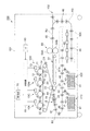
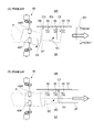
図1は、本実施の形態が適用される画像形成装置100をフロント側から眺めた場合の図である。
画像形成装置100には、電子写真方式により各色成分のトナー像を形成する複数の画像形成ユニット10(10Y、10M、10C、10K)が設けられている。
さらに、画像形成装置100には、CPU(Central Processing Unit)、ROM(Read Only Memory)などを含んで構成され、画像形成装置100を構成する各装置および各部の動作を制御する制御部80が設けられている。
Hereinafter, embodiments of the present invention will be described in detail with reference to the attached drawings.
FIG. 1 is a view from the front side of an
The
Furthermore, the
また、画像形成装置100には、ユーザインタフェース部(UI)90が設けられている。ユーザインタフェース部90は、表示パネルにより構成され、ユーザから受けた指示を制御部80に出力するとともに、制御部80からの情報をユーザに表示する。
Further, the
さらに、画像形成装置100には、各画像形成ユニット10にて形成された各色成分トナー像が順次転写(一次転写)される中間転写ベルト20、用紙Pに対して中間転写ベルト20上のトナー像を一括転写(二次転写)する二次転写装置30が設けられている。
ここで、各画像形成ユニット10、中間転写ベルト20、二次転写装置30は、用紙Pへの画像形成を行う画像形成手段として捉えることができる。
Further, in the
Here, each of the image forming units 10, the
また、画像形成装置100には、二次転写装置30に向けて搬送される用紙Pが通過する第1用紙搬送経路R1、二次転写装置30を通過した後の用紙Pが通過する第2用紙搬送経路R2、第2用紙搬送経路R2から分岐するとともに第1用紙搬送経路R1の下方まで延びる第3用紙搬送経路R3が設けられている。
Further, in the
さらに、第3用紙搬送経路R3から第1用紙搬送経路R1へ用紙Pを搬送するとともにこの用紙Pの表裏を反転する反転機構500が設けられている。また、画像形成装置100の筐体101には、開口102が形成されている。
第2用紙搬送経路R2に沿って搬送されてきた用紙Pは、この開口102を通じて筐体101の外部に排出され、不図示の用紙積載部上に積載される。なお、筐体101に隣接させて処理装置(不図示)を設け、開口102から排出されてくる用紙Pに対し穴あけなどの処理をさらに行ってもよい。
Further, a
The sheet P conveyed along the second sheet conveyance path R2 is discharged to the outside of the
さらに、第1用紙搬送経路R1に用紙Pを供給する第1用紙供給装置410、第2用紙供給装置420が設けられている。
第1用紙供給装置410および第2用紙供給装置420は、同様に構成されており、第1用紙供給装置410および第2用紙供給装置420の各々には、用紙Pを収容する用紙収容部41、用紙収容部41に収容された用紙Pを取り出して搬送する取り出しロール42が設けられている。
Further, a first
The first
二次転写装置30の上流側には、第1用紙搬送経路R1上の用紙Pを二次転写装置30に向けて搬送する第1搬送ロール(レジロール)44が設けられている。
第1搬送ロール44は、用紙Pを一端停止させ、予め定められたタイミングで、二次転写装置30に向けて用紙Pを搬送する。
さらに、第1搬送ロール44の上流側には、第1用紙搬送経路R1を搬送される用紙Pの側辺が突き当てられる突き当て部78が設けられている。この突き当て部78は、第1用紙搬送経路R1の一方の側方(一方の脇)に設けられている。
On the upstream side of the
The
Further, on the upstream side of the
さらに、突き当て部78よりも図中手前側(画像形成装置100の奥行き方向において突き当て部78よりも手前側)には、第2搬送ロール(アライメントロール)45が設けられている。突き当て手段の一例としてのこの第2搬送ロール45は、下流側への用紙Pの搬送を行うとともに、突き当て部78に向けて用紙Pを移動させ、用紙Pの側辺をこの突き当て部78に突き当てる。
Furthermore, a second transport roll (alignment roll) 45 is provided on the near side in the drawing (the near side of the
また、第2搬送ロール45よりも上流側には、下流側への用紙Pの搬送を行うとともに、必要に応じて用紙Pを回転(傾斜)させる第3搬送ロール(プレアライメントロール)46が設けられている。
第3搬送ロール46よりも上流側には、この第3搬送ロール46に向けて用紙Pを搬送する第4搬送ロール47が設けられている。
Further, on the upstream side of the
A
ここで、第1搬送ロール44〜第4搬送ロール47が設けられている箇所は、用紙Pを搬送する機能を有しており、第1搬送ロール44〜第4搬送ロール47が設けられている箇所は、用紙搬送装置として捉えることが可能である。
なお、本実施形態では、これらの搬送ロールの他に、第1用紙搬送経路R1、第2用紙搬送経路R2、および、第3用紙搬送経路R3には、これらの用紙搬送経路上に位置する用紙Pを搬送する搬送ロール48が複数設けられている。
Here, the places where the first to fourth conveyance rolls 44 to 47 are provided have the function of conveying the sheet P, and the first to
In the present embodiment, in addition to the transport rolls, the first sheet transport path R1, the second sheet transport path R2, and the third sheet transport path R3 are sheets located on these sheet transport paths. A plurality of
第2用紙搬送経路R2上には、二次転写装置30により用紙P上に二次転写された画像をこの用紙Pに定着させる定着装置50が設けられている。
さらに、二次転写装置30と定着装置50との間には、二次転写装置30を通過した用紙Pを定着装置50へ搬送する搬送装置51が設けられている。搬送装置51は、周回移動するベルト51Aを有し、このベルト51Aの上に用紙Pを載せて用紙Pを搬送する。
A
Further, between the
定着装置50には、内蔵されたヒータ(不図示)により加熱される加熱ロール50A、加熱ロール50Aを押圧する押圧ロール50Bが設けられている。
定着装置50では、加熱ロール50Aと押圧ロール50Bとの間を用紙Pが通過することで、用紙Pが加圧および加熱される。これにより用紙P上の画像が用紙Pに定着される。
The fixing
In the fixing
画像形成ユニット10の各々には、回転可能な感光体ドラム11が設けられている。また、感光体ドラム11の周囲には、感光体ドラム11を帯電する帯電装置12、感光体ドラム11を露光して静電潜像を書き込む露光装置13、感光体ドラム11上の静電潜像をトナーにより可視像化する現像装置14が設けられている。
さらに、感光体ドラム11上に形成された各色成分トナー像を中間転写ベルト20に転写する一次転写装置15、感光体ドラム11上の残留トナーを除去するドラム清掃装置16が設けられている。
Each of the image forming units 10 is provided with a rotatable
Further, a
中間転写ベルト20は、3本のロール部材21〜23に掛け渡され、回転するように設けられている。これら3本のロール部材21〜23のうち、ロール部材22は、中間転写ベルト20を駆動する。ロール部材23は、中間転写ベルト20を挟んで二次転写ロール31に対向配置されており、これら二次転写ロール31およびロール部材23によって二次転写装置30が構成される。中間転写ベルト20を挟んでロール部材21と対向する位置には、中間転写ベルト20上の残留トナーを除去するベルト清掃装置24が設けられている。
The
本実施形態の画像形成装置100では、第1用紙供給装置410等から供給された用紙Pの一方の面に画像を形成することができるのに加え、用紙Pの他方の面に画像を形成することができる。
具体的に説明すると、この画像形成装置100では、定着装置50を通過した用紙Pの表裏が反転機構500によって反転され、表裏が反転された用紙Pが、再度二次転写装置30へと搬送される。そして、二次転写装置30にて用紙Pの他方の面に対して画像が転写される。その後、この用紙Pは定着装置50を再び通過し、転写されたこの画像は用紙Pに定着される。これにより、用紙Pの一方の面のみならず他方の面にも画像が形成される。
In the
Specifically, in the
なお、反転機構500では、まず、第3用紙搬送経路R3上の用紙Pが、第3用紙搬送経路R3が延びる方向と直交する方向である、例えば画像形成装置100のフロント側に移動する。この移動は、不図示の専用の搬送ロールにより行われる。なお、このとき、第3用紙搬送経路R3上の搬送ロール48(反転機構500内に設置されている搬送ロール48)は離間した状態となっている。
In the reversing
上記直交する方向へ移動した用紙Pは、例えば、断面が略C字状の不図示のガイド部材により案内され上方へ向かう。また、上方への用紙Pの搬送を行う搬送ロール(不図示)が設けられており、この搬送ロールにより用紙Pはさらに上方へ向かう。 The sheet P moved in the orthogonal direction is guided by, for example, a guide member (not shown) having a substantially C-shaped cross section and travels upward. Further, a transport roll (not shown) for transporting the sheet P upward is provided, and the sheet P is further directed upward by the transport roll.
その後、この用紙Pは、第1用紙搬送経路R1の側方から第1用紙搬送経路R1上へ移動する。なお、このとき、第1用紙搬送経路R1上の搬送ロール48(反転機構500内に設置されている搬送ロール48)は離間している。
次いで、搬送ロール48により用紙Pがニップされるとともに、搬送ロール48が回転する。これにより、反転された後の用紙Pが二次転写装置30へ向かう。
Thereafter, the sheet P is moved onto the first sheet conveyance path R1 from the side of the first sheet conveyance path R1. At this time, the transport rolls 48 (the transport rolls 48 installed in the reversing mechanism 500) on the first sheet transport path R1 are separated.
Next, the sheet P is nipped by the
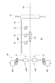
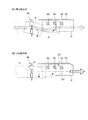
図2は、図1の矢印II方向から第1用紙搬送経路R1を眺めた場合の図である。
図2に示すように、また上記にて説明したように、本実施形態では、第1用紙搬送経路R1上の用紙Pを二次転写装置30(図1参照)に向けて搬送する第1搬送ロール(レジロール)44が設けられている。
FIG. 2 is a view of the case where the first sheet conveyance path R1 is viewed from the arrow II direction of FIG.
As shown in FIG. 2 and as described above, in the present embodiment, the first conveyance for conveying the sheet P on the first sheet conveyance path R1 toward the secondary transfer device 30 (see FIG. 1) A roll (registration roll) 44 is provided.
また、第1用紙搬送経路R1の一方の側方SR(リア側の側方)には、第1用紙搬送経路R1上の用紙Pの側辺が付き当てられる突き当て部78が設けられている。
突き当て部78は、板状に形成され、第1用紙搬送経路R1に沿って設けられている。
Further, on one side SR (side of the rear side) of the first sheet conveyance path R1, an abutting
The
突き当て部78に対峙する箇所には、下流側への用紙Pの搬送を行うとともに突き当て部78に向けて用紙Pを搬送し、突き当て部78へ用紙Pの側辺を突き当てる第2搬送ロール(アライメントロール)45が設けられている。第2搬送ロール45は、複数(本実施形態では3つ)設けられている。
第2搬送ロール45の各々は、傾斜した状態で配置されている。具体的には、第1用紙搬送経路R1が延びる方向と直交する方向に対して、第2搬送ロール45の回転軸が傾斜している。
The sheet P is conveyed to the downstream side at a location facing the butting
Each of the second transport rolls 45 is disposed in an inclined state. Specifically, the rotation axis of the
第3搬送ロール(プレアライメントロール)46には、用紙搬送手段の一例としてのフロント側ロール46F、リア側ロール46Rが設けられている。
フロント側ロール46F、リア側ロール46Rは、用紙Pが移動していく一方向(図中、矢印2Aで示す方向)と直交(交差)する方向において、互いにずらされた状態で配置されている。
The third transport roll (pre-alignment roll) 46 is provided with a
The
さらに、本実施形態では、フロント側ロール46Fを回転駆動するフロント側モータMF、リア側ロール46Rを回転駆動するリア側モータMRが設けられている。これにより、本実施形態では、フロント側ロール46F、リア側ロール46Rの回転駆動が個別に行われる。
Furthermore, in the present embodiment, a front side motor MF that rotationally drives the
フロント側ロール46Fは、一対の回転部材により構成され(図2では一方の回転部材のみを図示)、一方の回転部材が、フロント側モータMFにより回転し、他方の回転部材が、一方の回転部材に従動して回転する。
リア側ロール46Rも同様であり、一対の回転部材により構成され、一方の回転部材が、リア側モータMRにより回転し、他方の回転部材が、一方の回転部材に従動して回転する。
The
The
さらに、本実施形態では、第2搬送ロール45と第3搬送ロール46との間に、搬送されてきた用紙Pの先端(先端縁)を検知する2つのセンサCr、センサCfが設けられている。ここで、センサCrはリア側に配置され、センサCfはフロント側に配置されている。ここで、以下、本明細書では、センサCrをリアセンサCr、センサCfをフロントセンサCfと称する。
Furthermore, in the present embodiment, two sensors Cr and a sensor Cf that detect the leading edge (tip edge) of the sheet P conveyed are provided between the
図3は、第3搬送ロール46(フロント側ロール46F、リア側ロール46R)の制御に関する画像形成装置100の機能ブロック図である。
図3に示すように、フロント側モータMF、リア側モータMRは、制御部80に接続され、本実施形態では、制御部80によって、フロント側モータMF、リア側モータMRが制御される。制御部80は、用紙回転手段の一部として機能し、制御部80は、フロント側モータMF、リア側モータMRの回転数を異ならせることで、用紙Pの回転を行う(詳細は後述)。
FIG. 3 is a functional block diagram of the
As shown in FIG. 3, the front side motor MF and the rear side motor MR are connected to the
さらに、制御部80には、UI90が接続され、本実施形態では、UI90から制御部80に対して、用紙Pについての情報が出力される。具体的には、本実施形態では、ユーザが、UI90を介し、用紙Pについての情報を入力する。具体的には、用紙Pの坪量についての情報や、用紙Pの紙質についての情報を入力する。本実施形態では、この坪量についての情報や、紙質についての情報が、UI90から制御部80へ出力され、制御部80は、用紙Pの坪量や紙質を把握する。
Further, a
なお、本実施形態では、ユーザが坪量や紙質についての情報をUI90を通じて直接入力し、制御部80は、このように直接入力された情報に基づき、用紙Pの坪量や紙質を把握する。
ところで、このような態様に限らず、例えば、用紙Pの製品名等と、坪量や紙質についての情報との関係を記したテーブルをメモリに格納しておき、制御部80は、このテーブルを参照して、用紙Pの坪量や紙質を把握するようにしてもよい。
より具体的には、UI90では、用紙Pの製品名等についての情報をユーザに入力してもらうようにし、制御部80は、この製品名等およびテーブルに格納された情報に基づき、用紙Pの坪量や紙質を把握する。
In the present embodiment, the user directly inputs information on basis weight and paper quality through the
By the way, not limited to such an aspect, for example, a table in which the relationship between the product name of the sheet P and the information on the basis weight and the paper quality is stored is stored in the memory, and the
More specifically, in the
図4は、第3搬送ロール46の制御に関して制御部80が実行する処理の流れを示したフローチャートである。
本実施形態では、まず、制御部80は、用紙Pの搬送を開始する(ステップ101)。
具体的には、第1用紙供給装置410又は第2用紙供給装置420を駆動して、第1用紙搬送経路R1へ用紙Pを送り出すとともに、搬送ロール48を回転駆動して、第3搬送ロール46に向けての用紙Pを搬送する。
FIG. 4 is a flow chart showing a flow of processing executed by the
In the present embodiment, first, the
Specifically, the first
次に、制御部80は、UI90を通じてユーザが入力した、用紙Pについての情報を取得する(ステップ102)。ここでは、制御部80は、用紙Pの坪量についての情報を取得する。次いで、制御部80は、ステップ102にて取得した坪量についての情報に基づき、用紙P(ステップ101にて搬送を開始した用紙P)が厚紙であるかを判断する(ステップ103)。
Next, the
ここで、用紙Pが厚紙であるか否かは、ステップ102にて取得した坪量と、予め定められた坪量(閾値)とを比較し、ステップ102にて取得した坪量が、この予め定められた坪量よりも大きい場合に、厚紙であると判断する。
一方で、ステップ102にて取得した坪量が、この予め定められた坪量よりも小さい場合には、薄紙であると判断する。
Here, whether or not the paper P is thick paper is compared with the basis weight acquired in
On the other hand, if the basis weight obtained in
制御部80は、ステップ103にて、厚紙ではないと判断した場合(薄紙である場合)は、リア側ロール46Rの回転速度(回転数)Vrの方が、フロント側ロール46Fの回転速度Vfよりも大きくなるように、フロント側モータMF、リア側モータMRを駆動する(ステップ104)。
これに対し、ステップ103にて、厚紙であると判断した場合は、フロント側ロール46Fの回転速度Vfと、リア側ロール46Rの回転速度Vrとが同じとなるように、フロント側モータMF、リア側モータMRを駆動する(ステップ105)。
When the
On the other hand, when it is determined in step 103 that the sheet is thick paper, the front motor MF and the
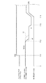
図5は、用紙Pとして薄紙が搬送される際のタイミングチャートを示した図である。
本実施形態では、まず、時間T11で、用紙Pの先端が検知される。より具体的には、リアセンサCr、フロントセンサCf(図2参照)によって、用紙Pの先端が検知される。
次いで、時間T12となると、フロント側ロール46Fが減速し、上記ステップ104にて説明したとおり、リア側ロール46Rの回転速度Vrの方が、フロント側ロール46Fの回転速度Vfよりも大きくなる。
FIG. 5 is a diagram showing a timing chart when thin paper is conveyed as the paper P. As shown in FIG.
In the present embodiment, first, at time T11, the leading edge of the sheet P is detected. More specifically, the leading edge of the sheet P is detected by the rear sensor Cr and the front sensor Cf (see FIG. 2).
Next, at time T12, the
これにより、本実施形態では、用紙Pが回転しながら下流側へ向かって移動する。
具体的には、用紙Pの先端が、画像形成装置100のフロント側を向くように用紙Pが回転し、さらに、この回転を伴いながら、用紙Pが下流側へ移動する。さらに説明すると、用紙Pの先端が、第1用紙搬送経路R1の他方の側方SF(図2参照)側を向くように用紙Pが回転し、用紙Pは、この回転を行いながら下流へ移動する。
Thus, in the present embodiment, the sheet P moves toward the downstream side while rotating.
Specifically, the sheet P is rotated so that the front end of the sheet P faces the front side of the
さらに説明すると、本実施形態では、用紙Pを回転させる際には、フロント側ロール46Fによる用紙Pの搬送速度と、リア側ロール46Rによる用紙Pの搬送速度との間に差を生じさせる。言い換えると、本実施形態では、フロント側ロール46F、リア側ロール46Rにおける用紙Pの搬送速度差を利用して、用紙Pを回転させる。
用紙Pをこのように回転させると、第1用紙搬送経路R1が延びる方向に対して、用紙Pが傾斜し、用紙Pの先端が、用紙Pの後端よりも画像形成装置100のフロント側に位置する。
Further, in the present embodiment, when the sheet P is rotated, a difference is generated between the conveyance speed of the sheet P by the
When the sheet P is thus rotated, the sheet P is inclined in the direction in which the first sheet conveyance path R1 extends, and the leading end of the sheet P is closer to the front side of the
なお、本実施形態では、フロント側ロール46Fを減速させることで用紙Pの回転を行ったが、リア側ロール46Rを増速することでも、用紙Pの回転は行える。
また、フロント側ロール46Fを減速させ、さらに、リア側ロール46Rを増速させて、用紙Pの回転を行ってもよい。
In the present embodiment, the sheet P is rotated by decelerating the
In addition, the paper P may be rotated by decelerating the
時間T13となると、リア側ロール46Rの回転速度Vr、フロント側ロール46Fの回転速度Vfは零となり、リア側ロール46R、フロント側ロール46Fは停止する。
なお、このとき、用紙Pは、第2搬送ロール45へ既に達しており、リア側ロール46R、フロント側ロール46Fが停止しても、下流側への用紙Pの搬送は行われる。
At time T13, the rotational speed Vr of the
At this time, the sheet P has already reached the
その後、本実施形態では、時間T14となると、第1搬送ロール44が回転を開始する。なお、この時間T14のときには、用紙Pの先端が、第1搬送ロール44に達した状態となっている。第1搬送ロール44が回転を開始すると、用紙Pは、二次転写装置30(図1参照)へ送り込まれる。なお、本実施形態では、第1搬送ロール44が回転を開始する際、リア側ロール46R、フロント側ロール46Fの回転も開始(再開)する。
Thereafter, in the present embodiment, at time T14, the
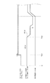
図6は、用紙Pとして厚紙が搬送される際のタイミングチャートを示した図である。
この場合、まず、時間T21で、用紙Pの先端が検知される。次いで、時間T22となると、リア側ロール46R、フロント側ロール46Fの減速を行うが、この際、フロント側ロール46Fのみを減速させずに、リア側ロール46R、フロント側ロール46Fの両者を減速する。
この結果、厚紙の場合は、用紙Pの回転は起こらず(用紙Pの回転量は零となり)、当初の姿勢を保ったまま、下流側へ用紙Pは搬送される。
FIG. 6 is a timing chart when thick paper is conveyed as the paper P. As shown in FIG.
In this case, first, at time T21, the leading edge of the sheet P is detected. Next, at time T22, the
As a result, in the case of thick paper, the rotation of the paper P does not occur (the rotation amount of the paper P is zero), and the paper P is transported downstream while maintaining the original posture.
なお、ここでは、厚紙の搬送時、用紙Pの回転量を零としたが、回転量を零とせず、薄紙の搬送時おける回転量よりも小さくしてもよい。さらに説明すると、上記のように1つの閾値のみを設定する処理ではなく(用紙Pを回転させるか回転させないかの二者択一の処理ではなく)、図7(坪量と回転量(搬送速度差)との関係を示した図)に示すように、用紙Pの坪量(厚さ)に応じて回転量を変化させてもよい。 Here, the amount of rotation of the sheet P is zero when transporting thick paper, but the amount of rotation may not be zero and may be smaller than the amount of rotation when transporting thin paper. To explain further, it is not the process of setting only one threshold as described above (not the process of selecting whether the sheet P is rotated or not rotated), and FIG. 7 (grammage and rotation amount (conveying speed) The amount of rotation may be changed in accordance with the basis weight (thickness) of the sheet P, as shown in FIG.
図8(A)、(B)は、用紙Pの動きを示した図である。
図8(A)は、薄紙が搬送される際の用紙Pの動きを示した図である。
用紙Pが薄紙である場合には、上記のとおり、リア側ロール46Rの回転速度Vrと、フロント側ロール46Fの回転速度Vfとの間に差が生じ、矢印9Aで示すように、用紙Pが回転する。具体的には、用紙Pの先端PFが画像形成装置100のフロント側を向くように、用紙Pが回転する。付言すると、用紙Pの先端PFが、第1用紙搬送経路R1の他方の側方SF側を向くように用紙Pが回転する。
FIGS. 8A and 8B show the movement of the sheet P. FIG.
FIG. 8A is a diagram showing the movement of the sheet P when thin paper is conveyed.
When the sheet P is thin, as described above, a difference occurs between the rotational speed Vr of the
次に、本実施形態では、第2搬送ロール45によって、用紙Pは、突き当て部78に向かい、符号9Bに示すように、用紙Pが有する4つの角部のうちの、後端側且つリア側に位置する角部CRが、突き当て部78に接触する。
次に、この用紙Pは、この角部CRを中心に、矢印9Cで示す方向に回転し、やがて、用紙Pの側辺PSの全体が突き当て部78に突き当たる。
Next, in the present embodiment, the sheet P is moved to the
Next, the sheet P rotates around the corner CR in the direction indicated by the
これにより、符号9Dで示すように、用紙Pが真っ直ぐな状態となる。
言い換えると、第1用紙搬送経路R1が延びる一方向に対して、用紙Pが沿い、用紙Pに傾きが生じていない状態となる。これにより、本実施形態では、用紙Pに形成される画像が、用紙Pの側辺PSに対して傾くなどの不具合が生じにくくなる。
As a result, as shown by reference numeral 9D, the sheet P is in a straight state.
In other words, the sheet P is along the one direction in which the first sheet conveyance path R1 extends, and the sheet P is not inclined. As a result, in the present embodiment, the image formed on the sheet P is less likely to have a problem such as tilting with respect to the side PS of the sheet P.
ここで、本実施形態では、薄紙の場合、突き当て部78に対して用紙Pを接触させる際、用紙Pの後端側の角部CRを敢えて接触させる。付言すると、用紙Pの先端側の角部CF(図8(A)参照)ではなく、後端側の角部CRを、突き当て部78に先に接触させる。
これにより、用紙Pの先端側の角部CFが、後端側の角部CRよりも先に突き当て部78に接触する場合に比べ、用紙Pの損傷が起きにくくなる。
Here, in the present embodiment, in the case of thin paper, when the sheet P is brought into contact with the
As a result, damage to the sheet P is less likely to occur compared to the case where the corner portion CF on the leading end side of the sheet P contacts the
図8(B)は、厚紙が搬送される際の用紙Pの動きを示した図である。
用紙Pが厚紙である場合、本実施形態では、リア側ロール46Rの回転速度Vrと、フロント側ロール46Fの回転速度Vfとの間に差を生じさせない。
このため、符号9Eで示すように、用紙Pは、その姿勢を変えることなく、リア側ロール46R、フロント側ロール46Fを通過する。
FIG. 8B shows the movement of the sheet P when the thick sheet is conveyed.
In the case where the sheet P is a thick sheet, in the present embodiment, there is no difference between the rotational speed Vr of the
For this reason, as indicated by
その後、第2搬送ロール45によって、用紙Pは、突き当て部78に向かい、突き当て部78に突き当たる。これにより、上記と同様、また、符号9Fに示すように、用紙Pが真っ直ぐな状態となる。
なお、厚紙の場合は、薄紙のような用紙Pの回転を行わないため、符号9Gで示すように、用紙Pの先端PF側の角部CFが突き当て部78に先に接触しやすくなる。しかしながら、厚紙の場合は、強度を有しているため、先端PF側の角部CFが突き当て部78に先に接触しても、用紙Pの損傷は起きにくい。
Thereafter, the sheet P is directed to the abutting
In the case of thick paper, since the paper P such as thin paper is not rotated, the corner portion CF on the leading end PF side of the paper P is likely to come into contact with the
図9は、比較例を示した図である。
この比較例では、本実施形態のように、リア側ロール46R、フロント側ロール46Fのように、独立して回転駆動する2つの部材を設けずに、1つのモータMで、第3搬送ロール46を駆動する。また、この比較例では、外径の異なる2つのロール部材81,82を設け、この2つのロール部材81,82の周速の差を利用して、用紙Pの回転を行う。
FIG. 9 is a diagram showing a comparative example.
In this comparative example, as in the present embodiment, the
図10(A)、(B)は、比較例における用紙Pの動きを示した図である。
上記のとおり、用紙Pが薄紙である場合は、用紙Pの損傷を抑制するため、用紙Pを回転させることが好ましくなる。
その一方で、厚紙については、用紙Pを回転させてしまうと、用紙Pが移動する際に通る経路が長くなり、用紙Pの搬送時間が長くなる。この場合、画像形成装置100における印刷効率が低下しやすくなる。特に、厚紙の搬送時は、薄紙の搬送時よりも搬送速度を低下させるのが一般的であり、用紙Pを回転させてしまうと、搬送速度がもともと小さいのと相まって、印刷効率(搬送効率)が大きく低下しやすい。
FIGS. 10A and 10B are diagrams showing the movement of the sheet P in the comparative example.
As described above, when the sheet P is a thin sheet, it is preferable to rotate the sheet P in order to suppress damage to the sheet P.
On the other hand, as for the thick paper, when the paper P is rotated, the path taken when the paper P moves is long, and the conveyance time of the paper P is long. In this case, the printing efficiency in the
図10(A)は、厚紙を回転させたときの用紙Pの動きを示した図である。
用紙Pを回転させると、突き当て部78から用紙Pが離れ、その後、用紙Pはこの突き当て部78に向かう。この場合、用紙Pの移動距離が増え、搬送効率、印刷効率が落ちる。
FIG. 10A shows the movement of the sheet P when the thick sheet is rotated.
When the sheet P is rotated, the sheet P is separated from the abutting
特に、上記のとおり、厚紙の搬送時は、薄紙の搬送時よりも搬送速度が小さく、用紙Pを回転させ、突き当て部78から用紙Pを離してしまうと、用紙Pの搬送効率が大きく低下しやすい。さらに説明すると、厚紙の搬送時は、本来ならば用紙Pの回転を行わないでよいにも関わらず、図10(A)にて示す搬送形態では、用紙Pが大きく回転し、この回転に起因して、用紙Pの搬送効率が落ちる。
In particular, as described above, when transporting thick paper, the transport speed is smaller than when transporting thin paper, and if the paper P is rotated and the paper P is released from the
このような搬送効率の低下は、ロール部材81(図9参照)の外径と、ロール部材82の外径との差を小さくすることで、その発生を抑えられるようになる。ところで、この場合は、薄紙において、用紙Pの損傷が生じやすくなる。
具体的には、ロール部材81の外径とロール部材82の外径との差を小さくすると、図10(B)に示すように、用紙Pの回転量が小さくなる。かかる場合、用紙Pの先端PF側の角部CFが突き当て部78に先に接触しやすくなり、用紙Pが損傷しやすくなる。
Such reduction in the transfer efficiency can be suppressed by reducing the difference between the outer diameter of the roll member 81 (see FIG. 9) and the outer diameter of the
Specifically, when the difference between the outer diameter of the
ここで、この損傷を防止するには、用紙Pの回転量を増やせばいいが、この場合は、上記のとおり、厚紙の搬送時に、搬送効率が落ちてしまう。
即ち、比較例では、薄紙を損傷なく搬送することと、厚紙を効率よく搬送することとを両立することが難しい。これに対し、本実施形態では、上記のとおり、用紙Pの坪量に応じて回転量を変えるため、この両立が可能になる。
Here, in order to prevent this damage, it is sufficient to increase the amount of rotation of the sheet P. In this case, as described above, the transport efficiency is lowered when the thick sheet is transported.
That is, in the comparative example, it is difficult to simultaneously transport thin paper without damage and efficiently transport thick paper. On the other hand, in the present embodiment, as described above, since the amount of rotation is changed according to the basis weight of the sheet P, this coexistence is possible.
なお、上記では、用紙Pの坪量に応じて用紙Pの回転量を変える場合を一例に説明したが、用紙種についての情報を取得するようにし、この用紙種に応じて回転量を変えるようにしてもよい。付言すると、リア側ロール46Rにおける用紙搬送速度、フロント側ロール46Fにおける用紙搬送速度を、用紙種毎に設定するようにしてもよい。これにより、用紙Pの回転量が用紙種毎に異なることを抑制できるようになる。
Although the case where the rotation amount of the paper P is changed according to the basis weight of the paper P has been described above as an example, information on the paper type is acquired, and the rotation amount is changed according to the paper type You may In addition, the sheet conveyance speed of the
ここで、坪量が同じであっても、例えば普通紙とコート紙とでは、用紙Pの表面の状態が異なり、用紙Pの回転量が異なることが起こりうる。かかる場合、一部の用紙種については、用紙Pの回転制御をしているにも関わらず、突き当て部78に先端側の角部CFが接触したり、突き当て部78から用紙Pが離れ搬送効率が低下したりすることが起こり得る。用紙種に応じて回転を制御するようにすれば、このような不具合の発生が抑制される。
Here, even if the basis weight is the same, for example, the surface state of the sheet P may be different between the plain paper and the coated sheet, and the rotation amount of the sheet P may be different. In such a case, for some sheet types, although the rotation control of the sheet P is performed, the corner portion CF on the tip side contacts the
10…各画像形成ユニット、20…中間転写ベルト、30…二次転写装置、44…第1搬送ロール、45…第2搬送ロール、46F…フロント側ロール、46R…リア側ロール、47…第4搬送ロール、78…突き当て部、80…制御部、P…用紙、PS…側辺、SF…他方の側方、SR…一方の側方、R1…第1用紙搬送経路 10: each image forming unit, 20: intermediate transfer belt, 30: secondary transfer device, 44: first conveyance roll, 45: second conveyance roll, 46F: front side roll, 46R: rear side roll, 47: fourth Conveying roll, 78: Abutment portion, 80: Control portion, P: Sheet, PS: Side side, SF: Other side, SR: One side, R1: First sheet conveying path
Claims (6)
前記搬送経路の一方の側方側に配置され、当該搬送経路上の用紙の側辺が突き当てられる用紙突き当て部と、
前記搬送経路上の用紙を前記一方の側方側に向けて移動させ、前記側辺を前記用紙突き当て部に突き当てる突き当て手段と、
前記突き当て手段よりも用紙の搬送方向上流側に位置し、前記一方向と交差する方向において互いにずらされて配置された2つの用紙搬送手段を有し、少なくとも一方の当該用紙搬送手段における用紙搬送速度を変更することができるように構成され、当該2つの用紙搬送手段における搬送速度差を利用して用紙を回転させる用紙回転手段と、
を備え、
前記用紙回転手段は、用紙の坪量が予め定められた坪量よりも大きい場合には、当該予め定められた坪量よりも小さい場合に比べて、用紙の回転量を小さくし、又は、回転量を零とする用紙搬送装置。 A transport path along which the sheet is transported in one direction;
A sheet abutment portion disposed on one side of the conveyance path, the side of the sheet on the conveyance path being abutted;
Abutment means for moving a sheet on the conveyance path toward the one side, and abutting the side to the sheet abutment portion;
It has two sheet conveying means which are located on the upstream side of the sheet conveying direction with respect to the abutting means and are mutually offset in the direction crossing the one direction, and the sheet conveyance in at least one of the sheet conveying means A sheet rotating unit configured to be capable of changing the speed, and rotating the sheet using a difference in conveying speed between the two sheet conveying units;
Equipped with
When the basis weight of the sheet is larger than a predetermined basis weight, the sheet rotating means makes the amount of rotation of the sheet smaller than when the basis weight of the sheet is smaller than the predetermined basis weight. sheet conveying device amount to zero.
前記搬送経路を搬送される用紙についての情報である用紙情報を取得する用紙情報取得手段と、
前記搬送経路の一方の側方側に配置され、当該搬送経路上の用紙の側辺が突き当てられる用紙突き当て部と、
前記搬送経路上の用紙を前記一方の側方側に向けて移動させ、前記側辺を前記用紙突き当て部に突き当てる突き当て手段と、
前記突き当て手段よりも用紙の搬送方向上流側に位置し、当該突き当て手段へ移動する用紙を回転させる用紙回転手段であり、取得された前記用紙情報に応じて、当該突き当て手段へ用紙が達する際の用紙の姿勢を異ならせるよう用紙を回転させる用紙回転手段と、
を備える用紙搬送装置。 A transport path along which the sheet is transported in one direction;
A sheet information acquisition unit that acquires sheet information that is information on a sheet conveyed on the conveyance path;
A sheet abutment portion disposed on one side of the conveyance path, the side of the sheet on the conveyance path being abutted;
Abutment means for moving a sheet on the conveyance path toward the one side, and abutting the side to the sheet abutment portion;
A sheet rotating means located upstream of the butting means in the conveyance direction of the sheet and rotating the sheet moving to the butting means, the sheet being transferred to the butting means according to the acquired sheet information. A sheet rotating unit configured to rotate the sheet so as to make the sheet different in attitude when reaching the sheet ;
Sheet conveying apparatus comprising:
前記画像形成手段に向かう用紙が通る搬送経路であって、用紙が一方向へ搬送される搬送経路と、
前記搬送経路の一方の側方側に配置され、当該搬送経路上の用紙の側辺が突き当てられる用紙突き当て部と、
前記搬送経路上の用紙を前記一方の側方側に向けて移動させ、前記側辺を前記用紙突き当て部に突き当てる突き当て手段と、
前記突き当て手段よりも用紙の搬送方向上流側に位置し、前記一方向と交差する方向において互いにずらされて配置された2つの用紙搬送手段を有し、少なくとも一方の当該用紙搬送手段における用紙搬送速度を変更することができるように構成され、当該2つの用紙搬送手段における搬送速度差を利用して用紙を回転させる用紙回転手段と、
を備え、
前記用紙回転手段は、用紙の坪量が予め定められた坪量よりも大きい場合には、当該予め定められた坪量よりも小さい場合に比べて、用紙の回転量を小さくし、又は、回転量を零とする画像形成装置。 An image forming unit for forming an image on a sheet;
A transport path through which the sheet toward the image forming unit passes, the transport path in which the sheet is transported in one direction;
A sheet abutment portion disposed on one side of the conveyance path, the side of the sheet on the conveyance path being abutted;
Abutment means for moving a sheet on the conveyance path toward the one side, and abutting the side to the sheet abutment portion;
It has two sheet conveying means which are located on the upstream side of the sheet conveying direction with respect to the abutting means and are mutually offset in the direction crossing the one direction, and the sheet conveyance in at least one of the sheet conveying means A sheet rotating unit configured to be capable of changing the speed, and rotating the sheet using a difference in conveying speed between the two sheet conveying units;
Equipped with
When the basis weight of the sheet is larger than a predetermined basis weight, the sheet rotating means makes the amount of rotation of the sheet smaller than when the basis weight of the sheet is smaller than the predetermined basis weight. the image forming apparatus amount to zero.
前記画像形成手段に向かう用紙が通る搬送経路であって、用紙が一方向へ搬送される搬送経路と、
前記搬送経路を搬送される用紙についての情報である用紙情報を取得する用紙情報取得手段と、
前記搬送経路の一方の側方側に配置され、当該搬送経路上の用紙の側辺が突き当てられる用紙突き当て部と、
前記搬送経路上の用紙を前記一方の側方側に向けて移動させ、前記側辺を前記用紙突き当て部に突き当てる突き当て手段と、
前記突き当て手段よりも用紙の搬送方向上流側に位置し、当該突き当て手段へ移動する用紙を回転させる用紙回転手段であり、取得された前記用紙情報に応じて、当該突き当て手段へ用紙が達する際の用紙の姿勢を異ならせるよう用紙を回転させる用紙回転手段と、
を備える画像形成装置。 An image forming unit for forming an image on a sheet;
A transport path through which the sheet toward the image forming unit passes, the transport path in which the sheet is transported in one direction;
A sheet information acquisition unit that acquires sheet information that is information on a sheet conveyed on the conveyance path;
A sheet abutment portion disposed on one side of the conveyance path, the side of the sheet on the conveyance path being abutted;
Abutment means for moving a sheet on the conveyance path toward the one side, and abutting the side to the sheet abutment portion;
A sheet rotating means located upstream of the butting means in the conveyance direction of the sheet and rotating the sheet moving to the butting means, the sheet being transferred to the butting means according to the acquired sheet information. A sheet rotating unit configured to rotate the sheet so as to make the sheet different in attitude when reaching the sheet ;
An image forming apparatus comprising:
Priority Applications (2)
| Application Number | Priority Date | Filing Date | Title |
|---|---|---|---|
| JP2015067615A JP6543995B2 (en) | 2015-03-27 | 2015-03-27 | Paper conveying apparatus and image forming apparatus |
| US14/841,910 US9555992B2 (en) | 2015-03-27 | 2015-09-01 | Sheet transport device and image forming apparatus |
Applications Claiming Priority (1)
| Application Number | Priority Date | Filing Date | Title |
|---|---|---|---|
| JP2015067615A JP6543995B2 (en) | 2015-03-27 | 2015-03-27 | Paper conveying apparatus and image forming apparatus |
Publications (2)
| Publication Number | Publication Date |
|---|---|
| JP2016185878A JP2016185878A (en) | 2016-10-27 |
| JP6543995B2 true JP6543995B2 (en) | 2019-07-17 |
Family
ID=56975246
Family Applications (1)
| Application Number | Title | Priority Date | Filing Date |
|---|---|---|---|
| JP2015067615A Active JP6543995B2 (en) | 2015-03-27 | 2015-03-27 | Paper conveying apparatus and image forming apparatus |
Country Status (2)
| Country | Link |
|---|---|
| US (1) | US9555992B2 (en) |
| JP (1) | JP6543995B2 (en) |
Families Citing this family (5)
| Publication number | Priority date | Publication date | Assignee | Title |
|---|---|---|---|---|
| US10160237B2 (en) * | 2016-11-02 | 2018-12-25 | Xerox Corporation | Cross roll registration system with controlled input positioning |
| JP6980439B2 (en) * | 2017-07-24 | 2021-12-15 | キヤノン株式会社 | Sheet transfer device |
| JP2019023136A (en) * | 2017-07-24 | 2019-02-14 | キヤノン株式会社 | Sheet conveying device |
| JP6921672B2 (en) * | 2017-07-24 | 2021-08-18 | キヤノン株式会社 | Sheet transfer device |
| US10442219B2 (en) * | 2018-01-16 | 2019-10-15 | Xerox Corporation | Dual edge registered sheets to mitigate print head jet dry out on short sheets within inkjet cut sheet printing |
Family Cites Families (13)
| Publication number | Priority date | Publication date | Assignee | Title |
|---|---|---|---|---|
| JPS60258037A (en) * | 1984-05-31 | 1985-12-19 | Fuji Xerox Co Ltd | Paper turning and transporting apparatus |
| JPH06166451A (en) * | 1992-11-30 | 1994-06-14 | Fuji Xerox Co Ltd | Paper sheet registration device |
| JPH06191684A (en) | 1992-12-24 | 1994-07-12 | Nec Corp | Inserter type printer |
| JPH10153891A (en) * | 1996-11-25 | 1998-06-09 | Fuji Xerox Co Ltd | Image forming device |
| JP2001151388A (en) * | 1999-11-30 | 2001-06-05 | Fuji Xerox Co Ltd | Sheet conveying device |
| JP2002060097A (en) | 2000-08-21 | 2002-02-26 | Fuji Xerox Co Ltd | Sheet conveying equipment |
| JP4385627B2 (en) * | 2003-03-24 | 2009-12-16 | 富士ゼロックス株式会社 | Sheet conveying apparatus and sheet processing apparatus using the same |
| US7637499B2 (en) * | 2006-02-09 | 2009-12-29 | Canon Kabushiki Kaisha | Sheet feeding apparatus and recording apparatus |
| JP4845658B2 (en) * | 2006-04-07 | 2011-12-28 | キヤノン株式会社 | Sheet conveying apparatus and image forming apparatus provided with the same |
| US7959150B2 (en) * | 2009-04-29 | 2011-06-14 | Xerox Corporation | Early carriage reset move for laterally movable registration device |
| US20110042887A1 (en) * | 2009-08-18 | 2011-02-24 | Kallin Fredrik L N | Document deskewing module and methods of operating a document deskewing module for a self-service bunch document depositing terminal |
| JP5963419B2 (en) * | 2011-11-07 | 2016-08-03 | キヤノン株式会社 | Image forming apparatus |
| US9280118B2 (en) * | 2013-10-09 | 2016-03-08 | Canon Kabushiki Kaisha | Image forming apparatus |
-
2015
- 2015-03-27 JP JP2015067615A patent/JP6543995B2/en active Active
- 2015-09-01 US US14/841,910 patent/US9555992B2/en active Active
Also Published As
| Publication number | Publication date |
|---|---|
| JP2016185878A (en) | 2016-10-27 |
| US20160282783A1 (en) | 2016-09-29 |
| US9555992B2 (en) | 2017-01-31 |
Similar Documents
| Publication | Publication Date | Title |
|---|---|---|
| JP5404209B2 (en) | Sheet conveying apparatus and image forming apparatus | |
| JP6543995B2 (en) | Paper conveying apparatus and image forming apparatus | |
| JP4810407B2 (en) | Sheet feeding apparatus and image forming apparatus | |
| JP6477136B2 (en) | Paper conveying apparatus and image forming apparatus | |
| JP2000233853A (en) | Image forming device and paper bundle forming device and paper bundle forming method employing image forming device | |
| JP5753870B2 (en) | Curl correction device and image forming apparatus provided with the same | |
| JP2015199551A (en) | Sheet conveying device and image formation apparatus | |
| JP2014034459A (en) | Recording medium conveyance device and image forming apparatus | |
| US9751708B2 (en) | Sheet transport device and image forming apparatus | |
| US11724899B2 (en) | Sheet conveyance apparatus and image forming apparatus | |
| JP6554855B2 (en) | Posture correction apparatus and image forming apparatus | |
| JP2006036493A (en) | Sheet handling device and image forming device equipped with it | |
| JP4378317B2 (en) | Paper folding device, paper processing device, and image forming device | |
| JP2022083480A (en) | Sheet conveyance device and image formation device | |
| JP6525938B2 (en) | Seat position correction device | |
| JP2015009971A (en) | Fold formation device, post-processing device and image formation device | |
| JP7000064B2 (en) | Sheet transfer device and image forming device | |
| JP2019182571A (en) | Image forming device | |
| JP2016013905A (en) | Image forming apparatus | |
| JP6624840B2 (en) | Image forming device | |
| JP2006219290A (en) | Paper folder and image forming device | |
| JP2011132022A (en) | Sheet carrying device and image forming device | |
| JP5799573B2 (en) | Image forming apparatus and recording material processing apparatus | |
| JP2018140869A (en) | Image forming apparatus | |
| JP6245868B2 (en) | Sheet conveying apparatus and image forming apparatus |
Legal Events
| Date | Code | Title | Description |
|---|---|---|---|
| A621 | Written request for application examination |
Free format text: JAPANESE INTERMEDIATE CODE: A621 Effective date: 20180228 |
|
| A977 | Report on retrieval |
Free format text: JAPANESE INTERMEDIATE CODE: A971007 Effective date: 20181116 |
|
| A131 | Notification of reasons for refusal |
Free format text: JAPANESE INTERMEDIATE CODE: A131 Effective date: 20181127 |
|
| A521 | Request for written amendment filed |
Free format text: JAPANESE INTERMEDIATE CODE: A523 Effective date: 20190125 |
|
| TRDD | Decision of grant or rejection written | ||
| A01 | Written decision to grant a patent or to grant a registration (utility model) |
Free format text: JAPANESE INTERMEDIATE CODE: A01 Effective date: 20190521 |
|
| A61 | First payment of annual fees (during grant procedure) |
Free format text: JAPANESE INTERMEDIATE CODE: A61 Effective date: 20190603 |
|
| R150 | Certificate of patent or registration of utility model |
Ref document number: 6543995 Country of ref document: JP Free format text: JAPANESE INTERMEDIATE CODE: R150 |
|
| S533 | Written request for registration of change of name |
Free format text: JAPANESE INTERMEDIATE CODE: R313533 |
|
| R350 | Written notification of registration of transfer |
Free format text: JAPANESE INTERMEDIATE CODE: R350 |