JP6979021B2 - Devices and methods for advancing wires - Google Patents
Devices and methods for advancing wires Download PDFInfo
- Publication number
- JP6979021B2 JP6979021B2 JP2018536423A JP2018536423A JP6979021B2 JP 6979021 B2 JP6979021 B2 JP 6979021B2 JP 2018536423 A JP2018536423 A JP 2018536423A JP 2018536423 A JP2018536423 A JP 2018536423A JP 6979021 B2 JP6979021 B2 JP 6979021B2
- Authority
- JP
- Japan
- Prior art keywords
- catheter
- lumen
- catheters
- vessel
- alignment element
- Prior art date
- Legal status (The legal status is an assumption and is not a legal conclusion. Google has not performed a legal analysis and makes no representation as to the accuracy of the status listed.)
- Active
Links
Images


Classifications
-
- A—HUMAN NECESSITIES
- A61—MEDICAL OR VETERINARY SCIENCE; HYGIENE
- A61M—DEVICES FOR INTRODUCING MEDIA INTO, OR ONTO, THE BODY; DEVICES FOR TRANSDUCING BODY MEDIA OR FOR TAKING MEDIA FROM THE BODY; DEVICES FOR PRODUCING OR ENDING SLEEP OR STUPOR
- A61M25/00—Catheters; Hollow probes
- A61M25/0021—Catheters; Hollow probes characterised by the form of the tubing
-
- A—HUMAN NECESSITIES
- A61—MEDICAL OR VETERINARY SCIENCE; HYGIENE
- A61M—DEVICES FOR INTRODUCING MEDIA INTO, OR ONTO, THE BODY; DEVICES FOR TRANSDUCING BODY MEDIA OR FOR TAKING MEDIA FROM THE BODY; DEVICES FOR PRODUCING OR ENDING SLEEP OR STUPOR
- A61M25/00—Catheters; Hollow probes
- A61M25/01—Introducing, guiding, advancing, emplacing or holding catheters
- A61M25/0105—Steering means as part of the catheter or advancing means; Markers for positioning
- A61M25/0127—Magnetic means; Magnetic markers
-
- A—HUMAN NECESSITIES
- A61—MEDICAL OR VETERINARY SCIENCE; HYGIENE
- A61M—DEVICES FOR INTRODUCING MEDIA INTO, OR ONTO, THE BODY; DEVICES FOR TRANSDUCING BODY MEDIA OR FOR TAKING MEDIA FROM THE BODY; DEVICES FOR PRODUCING OR ENDING SLEEP OR STUPOR
- A61M25/00—Catheters; Hollow probes
- A61M25/01—Introducing, guiding, advancing, emplacing or holding catheters
- A61M25/0194—Tunnelling catheters
-
- A—HUMAN NECESSITIES
- A61—MEDICAL OR VETERINARY SCIENCE; HYGIENE
- A61M—DEVICES FOR INTRODUCING MEDIA INTO, OR ONTO, THE BODY; DEVICES FOR TRANSDUCING BODY MEDIA OR FOR TAKING MEDIA FROM THE BODY; DEVICES FOR PRODUCING OR ENDING SLEEP OR STUPOR
- A61M25/00—Catheters; Hollow probes
- A61M25/01—Introducing, guiding, advancing, emplacing or holding catheters
- A61M25/09—Guide wires
- A61M25/09041—Mechanisms for insertion of guide wires
-
- A—HUMAN NECESSITIES
- A61—MEDICAL OR VETERINARY SCIENCE; HYGIENE
- A61M—DEVICES FOR INTRODUCING MEDIA INTO, OR ONTO, THE BODY; DEVICES FOR TRANSDUCING BODY MEDIA OR FOR TAKING MEDIA FROM THE BODY; DEVICES FOR PRODUCING OR ENDING SLEEP OR STUPOR
- A61M25/00—Catheters; Hollow probes
- A61M25/01—Introducing, guiding, advancing, emplacing or holding catheters
- A61M2025/018—Catheters having a lateral opening for guiding elongated means lateral to the catheter
-
- A—HUMAN NECESSITIES
- A61—MEDICAL OR VETERINARY SCIENCE; HYGIENE
- A61M—DEVICES FOR INTRODUCING MEDIA INTO, OR ONTO, THE BODY; DEVICES FOR TRANSDUCING BODY MEDIA OR FOR TAKING MEDIA FROM THE BODY; DEVICES FOR PRODUCING OR ENDING SLEEP OR STUPOR
- A61M25/00—Catheters; Hollow probes
- A61M25/01—Introducing, guiding, advancing, emplacing or holding catheters
- A61M25/0194—Tunnelling catheters
- A61M2025/0197—Tunnelling catheters for creating an artificial passage within the body, e.g. in order to go around occlusions
Description
(関連出願の引用)
本願は、米国仮出願第62/279,650号(2016年1月15日出願、名称「DEVICES AND METHODS FOR ADVANCING A WIRE」)に対する優先権を主張し、上記出願は、その全体が参照により本明細書に引用される。
(Quotation of related application)
This application claims priority to US Provisional Application No. 62 / 279,650 (filed January 15, 2016, named "DEVICES AND METHODS FOR ADVANCEING A WIRE"), which is the entire application by reference. Cited in the specification.
(分野)
本発明は、ワイヤを前進させるためのシステムおよび方法に関する。システムおよび方法は、1つ以上の脈管壁を通してワイヤを前進させる、例えば、脈管内の閉塞をバイパスするために使用され得る。
(Field)
The present invention relates to systems and methods for advancing wires. Systems and methods can be used to advance the wire through one or more vessel walls, eg, to bypass obstruction within the vessel.
いくつかの経皮的手技の間、ツールを第1の脈管(例えば、静脈または動脈)から第2の近傍脈管(例えば、第2の静脈または動脈)に前進させることが必要または望まくしあり得る。これは、瘻孔を2つの脈管間に形成するための手技において特に望ましくあり得る。瘻孔は、概して、2つの内部器官間に形成される通路である。瘻孔を2つの血管間に形成することは、1つ以上の有益である機能を有することができる。例えば、動脈と静脈との間の瘻孔の形成は、血液透析患者のための血管系へのアクセスを提供し得る。具体的には、動脈と静脈との間の瘻孔の形成は、毛細管をバイパスしながら、血液が脈管間に急速に流動することを可能にする。他の事例では、瘻孔は、2つの静脈間に形成され、静静脈瘻孔を形成し得る。故に、したがって、瘻孔作成の間に使用され得る、2つの脈管間の経路におよびそこからアクセスするための改良された方法を見出すことが有用であり得る。 During some percutaneous procedures, it is necessary or desirable to advance the tool from the first vein (eg, vein or artery) to the second nearby vessel (eg, second vein or artery). possible. This may be particularly desirable in the procedure for forming a fistula between two vessels. A fistula is generally a passage formed between two internal organs. Forming a fistula between two blood vessels can have one or more beneficial functions. For example, the formation of a fistula between an artery and a vein may provide access to the vasculature for hemodialysis patients. Specifically, the formation of a fistula between an artery and a vein allows blood to flow rapidly between the vessels while bypassing the capillaries. In other cases, a fistula is formed between two veins and can form a static venous fistula. Therefore, it may be useful to find an improved way to access and from the route between the two vessels that can be used during fistula creation.
加えて、経路を2つの血管間に形成し、脈管のうちの1つ内の閉塞または障壁を回避またはバイパスし、種々の疾患の治療をもたらすことが必要または望ましくあり得る。人々は、治療されないままにされる場合、重症下肢虚血(CLI)に進行し得る、末梢血管疾患(PVD)を含む、いくつかの理由から、閉塞された脈管に悩まされ得る。CLIは、慢性疼痛ならびに組織損失によって特徴付けられ、これは、最終的には、切断をもたらし得る。切断は、コストがかかるだけではなく、また、肢切断者にとって生活の質の有意な損失につながり、いくつかの不幸な場合では、患者の死亡をもたらす。故に、したがって、閉塞の周囲の血流にアクセスし、代替経路を作成するための改良された方法を見出すことが有用であり得る。 In addition, it may be necessary or desirable to form a pathway between two blood vessels to avoid or bypass obstruction or barriers within one of the vessels, resulting in treatment of various diseases. People can suffer from obstructed vessels for several reasons, including peripheral vascular disease (PVD), which can progress to severe lower extremity ischemia (CLI) if left untreated. CLI is characterized by chronic pain as well as tissue loss, which can ultimately result in amputation. Amputations are not only costly, but also lead to a significant loss of quality of life for amputees, leading to patient death in some unfortunate cases. Therefore, it may be useful to find an improved way to access the blood flow around the obstruction and create an alternative pathway.
経路を2つの脈管間または脈管と空洞との間に形成するために、高正確度を伴って、ガイドワイヤまたは針を第1の脈管管腔または空洞から別の脈管管腔または空洞に送達することが必要または望ましくあり得る。これは、不必要または不正確な貫通を防止し得る。例えば、腹部下大静脈から大動脈の中へのガイドワイヤの通過の間、ガイドワイヤは、大静脈から大動脈に正確に送達され、大静脈および/または大動脈内における潜在的に損傷させる不正確または不必要な貫通を防止するべきである。加えて、高正確度システムおよび方法はまた、脈管にアクセスし、貫通することが、脈管直径が減少するにつれてより困難になり得るため、小脈管へのガイドワイヤまたは針の送達を補助し得る。より大きい脈管では、ツールが脈管壁に十分に近接して位置されない場合、または脈管壁自体があまりに多くの空間をそれらの間に有する場合、経路を脈管間に作成することが困難であり得る。したがって、場合によっては、ガイドワイヤまたは針が所望の経路を作成するために減少された進行距離をもたらし得るため、および/またはより少ない整列誤差をもたらし得るため、脈管間の経路が作成される前に、または脈管壁に近接して位置させるために使用されるツールのために、脈管を一緒により近づけるように移動させることが有益であり得る。故に、ワイヤを標的場所に送達し、経路を脈管間に作成するための正確なシステムおよび方法を見出すことが有用であり得る。加えて、経路形成の間、脈管間またはツールと脈管壁との間の距離を減少させる、システムおよび方法も、有用であり得る。 With high accuracy, guide wires or needles from the first vessel or cavity to another vessel or cavity to form a path between the two vessels or between the vessel and the cavity. It may be necessary or desirable to deliver to the cavity. This can prevent unnecessary or inaccurate penetration. For example, during the passage of the guidewire from the inferior vena cava into the aorta, the guidewire is delivered accurately from the vena cava to the aorta, with inaccuracies or inaccuracies that potentially damage the vena cava and / or the aorta. The necessary penetration should be prevented. In addition, high accuracy systems and methods also aid in the delivery of guide wires or needles to the tubules, as accessing and penetrating the vasculature can become more difficult as the vascular diameter decreases. Can be done. For larger vessels, it is difficult to create a pathway between the vessels if the tool is not located close enough to the vessel wall, or if the vessel wall itself has too much space between them. Can be. Thus, in some cases, a route between vessels is created because the guidewire or needle can result in a reduced travel distance to create the desired route and / or can result in less alignment error. It may be beneficial to move the vessels closer together, either forward or because of the tools used to position them closer to the vessel wall. Therefore, it may be useful to find the exact system and method for delivering the wire to the target location and creating a pathway between the vessels. In addition, systems and methods that reduce the distance between the vessels or between the tool and the vessel wall during pathway formation may also be useful.
いくつかの事例では、増加されたシステム複雑性または複数の可視化モードの利用は、臨床設定において望ましくない場合がある。故に、所望の場所の中への送達成功のために整列が単純かつ有意な時間または労力を要求しない、システムおよび方法を開発することが有用であり得る。 In some cases, increased system complexity or the use of multiple visualization modes may not be desirable in a clinical setting. Therefore, it may be useful to develop systems and methods in which alignment is simple and does not require significant time or effort for successful delivery into the desired location.
本明細書に説明されるのは、ワイヤを管腔壁を通して第1の腔内空間から第2の腔内空間に前進させるための、ならびに脈管内の閉塞または障壁のバイパスを含む、多くの使用のためのシステムおよび方法である。概して、本明細書に説明されるシステムは、複数のカテーテルを備え得る。いくつかの変形例では、本明細書に説明されるシステムおよび方法は、第1のカテーテルと、第2のカテーテルとを備え得る。他の変形例では、本明細書に説明されるシステムおよび方法は、第1のカテーテルと、第2のカテーテルと、第3のカテーテルとを備え得る。 A number of uses are described herein for advancing a wire through a luminal wall from a first luminal space to a second luminal space, as well as including intravascular obstruction or barrier bypass. Is a system and method for. In general, the system described herein may include multiple catheters. In some variants, the systems and methods described herein may comprise a first catheter and a second catheter. In another variant, the systems and methods described herein may include a first catheter, a second catheter, and a third catheter.
いくつかの変形例では、本明細書に説明されるシステムは、第1のカテーテルと、第2のカテーテルと、ガイドワイヤとを備え得る。第1のカテーテルは、それを通る第1の管腔と第1の側面開口とを有するカテーテル本体と、第1の偏向表面と、第1の整列要素とを備え得る。第2のカテーテルは、それを通る第2の管腔と第2の側面開口とを有するカテーテル本体と、第2の偏向表面と、第2の整列要素とを備え得る。第3のカテーテルは、それを通る管腔と第4の側面開口とを有するカテーテル本体と、管腔内に位置付けられる第4の偏向器と、第4の整列要素とを備え得る。いくつかの変形例では、第1および第2の整列要素は、第1および第2の側面開口を整列させ、第1および第2のカテーテルを通るガイドワイヤ経路を作成するように構成され得る。 In some variants, the system described herein may include a first catheter, a second catheter, and a guide wire. The first catheter may comprise a catheter body having a first lumen and a first lateral opening through it, a first deflection surface, and a first alignment element. The second catheter may comprise a catheter body having a second lumen and a second lateral opening through it, a second deflection surface, and a second alignment element. The third catheter may comprise a catheter body having a lumen through it and a fourth lateral opening, a fourth deflector located within the lumen, and a fourth alignment element. In some variants, the first and second alignment elements may be configured to align the first and second side openings and create a guidewire path through the first and second catheters.
いくつかの変形例では、第1のカテーテルは、送達カテーテルであり、第2のカテーテルは、受け取りカテーテルである。第1および第2の整列要素の各々は、磁石または磁石アレイを備え得る。いくつかの変形例では、第1のカテーテルはさらに、第3の整列要素を備え得、第2のカテーテルは、第4の整列要素を備え得る。これらの変形例のいくつかでは、第3および第4の整列要素の各々は、磁石または磁石アレイを備え得る。第1の整列要素は、第1の側面開口の近位に位置付けられ得、第3の整列要素は、第1の側面開口の遠位に位置付けられ得る。第1の偏向表面は、第1および第3の整列要素間に位置付けられ得る。第2の整列要素は、第2の側面開口の遠位に位置付けられ得、第4の整列要素は、第2の側面開口の近位に位置付けられ得る。第2の偏向表面は、第2および第4の整列要素間に位置付けられ得る。これらの変形例のいくつかでは、第1の整列要素は、第2の整列要素と一致するように構成され得、第3の整列要素は、第4の整列要素と一致するように構成され得る。第1および第2のカテーテルは、縦に整列させられるように構成される。これらの変形例の別のものでは、第1の整列要素は、それにガイドワイヤを通すように構成されている、管腔を備え得る。第4の整列要素は、それにガイドワイヤを通すように構成されている、管腔を備え得る。 In some variants, the first catheter is the delivery catheter and the second catheter is the receiving catheter. Each of the first and second alignment elements may include a magnet or a magnet array. In some variants, the first catheter may further comprise a third alignment element and the second catheter may comprise a fourth alignment element. In some of these variants, each of the third and fourth alignment elements may include a magnet or a magnet array. The first alignment element may be located proximal to the first side opening and the third alignment element may be located distal to the first side opening. The first deflection surface can be positioned between the first and third alignment elements. The second alignment element may be located distal to the second lateral opening and the fourth alignment element may be located proximal to the second lateral opening. The second deflection surface can be positioned between the second and fourth alignment elements. In some of these variants, the first alignment element may be configured to match the second alignment element, and the third alignment element may be configured to match the fourth alignment element. .. The first and second catheters are configured to be vertically aligned. In another of these variants, the first alignment element may comprise a lumen configured to pass a guide wire through it. The fourth alignment element may comprise a lumen configured to pass a guide wire through it.
システムは、1つ以上の追加の特徴を含み得る。いくつかの変形例では、第1のカテーテルは、第1の管腔内に位置付けられている第1の偏向器を備え、第1の偏向表面を備え得、第2のカテーテルは、第2の管腔内に位置付けられている第2の偏向器を備え、第2の偏向表面を備え得る。いくつかの変形例では、第1および第2のカテーテルは、第1および第2の偏向表面の傾きが同一符号を有するように配列され得る。いくつかの変形例では、第1および第2の偏向表面の一方または両方は、湾曲され得る。いくつかの変形例では、第2のカテーテルはさらに、ガイドワイヤの遠位先端を第2の管腔の中に指向するように構成される、導糸管を備え得る。第1および第2のカテーテルの各々は、非外傷性先端を備え得る。 The system may include one or more additional features. In some variants, the first catheter may include a first deflector located within a first lumen and a first deflecting surface, the second catheter may be a second. It may include a second deflector located within the lumen and a second deflecting surface. In some variants, the first and second catheters may be arranged such that the tilts of the first and second deflection surfaces have the same sign. In some variants, one or both of the first and second deflection surfaces can be curved. In some variants, the second catheter may further comprise a thread tube configured to direct the distal tip of the guidewire into the second lumen. Each of the first and second catheters may be equipped with a non-traumatic tip.
また、本明細書に説明されるのは、脈管内の閉塞をバイパスするための他のシステムである。一般に、これらのシステムは、第1のカテーテルと、第2のカテーテルと、第3のカテーテルと、ガイドワイヤとを備え得る。第1のカテーテルは、それを通る第1の管腔と第1の側面開口とを有するカテーテル本体と、第1の整列要素とを備え得る。第2のカテーテルは、それを通る第2の管腔と第2および第3の側面開口とを有するカテーテル本体と、第2および第3の整列要素とを備え得る。第3のカテーテルは、それを通る第3の管腔と第4の側面開口とを有するカテーテル本体と、第4の整列要素とを備え得る。いくつかの変形例では、第1および第2の整列要素は、第1および第2の側面開口を整列させるように構成され得る。第3および第4の整列要素は、第3および第4の側面開口を整列させ、第1、第2、および第3のカテーテルを通るガイドワイヤ経路を作成するように構成され得る。 Also described herein are other systems for bypassing intravascular obstruction. In general, these systems may include a first catheter, a second catheter, a third catheter, and a guide wire. The first catheter may comprise a catheter body having a first lumen through it and a first lateral opening, and a first alignment element. The second catheter may comprise a catheter body having a second lumen through it and second and third lateral openings, and a second and third alignment element. The third catheter may comprise a catheter body having a third lumen through it and a fourth lateral opening, and a fourth alignment element. In some variants, the first and second alignment elements may be configured to align the first and second side openings. The third and fourth alignment elements can be configured to align the third and fourth side openings and create guidewire paths through the first, second, and third catheters.
いくつかの変形例では、第1のカテーテルは、送達カテーテルであり得、第2のカテーテルは、バイパスカテーテルであり得、第3のカテーテルは、受け取りカテーテルであり得る。第1、第2、第3、および第4の整列要素の各々は、磁石または磁石アレイを備え得る。第2のカテーテルは、第2および第3の側面開口間の細隙、弱体部分、穿孔を備え得る。 In some variants, the first catheter can be a delivery catheter, the second catheter can be a bypass catheter, and the third catheter can be a receiving catheter. Each of the first, second, third, and fourth alignment elements may include a magnet or a magnet array. The second catheter may include a gap, a weakened portion, a perforation between the second and third lateral openings.
いくつかの変形例では、第1のカテーテルはさらに、第1の管腔内に位置付けられている第1の偏向器を備え得、第2のカテーテルはさらに、第2の管腔内に位置付けられている第2および第3の偏向器を備え得、第3のカテーテルはさらに、第4の管腔内に位置付けられている第4の偏向器を備え得る。これらの変形例のいくつかでは、第1、第2、第3、および第4の偏向器の各々は、偏向表面を備え得る。これらの変形例のいくつかでは、第1、第2、および第3のカテーテルは、偏向表面のうちの3つのものの傾きが同一符号を有し、第4の偏向表面の傾きが反対符号を有するように配列され得る。 In some variants, the first catheter may further comprise a first deflector located in the first lumen, and the second catheter is further positioned in the second lumen. The third catheter may further include a fourth deflector located within the fourth lumen. In some of these variants, each of the first, second, third, and fourth deflectors may comprise a deflecting surface. In some of these variants, the first, second, and third catheters have the same tilt of three of the deflection surfaces and the opposite tilt of the fourth deflection surface. Can be arranged as
これらの変形例の他のものでは、第1、第2、および第3のカテーテルは、第1の偏向器が正の傾きを伴う第1の偏向表面を備え、第2の偏向器が負の傾きを伴う第2の偏向表面を備え、第3の偏向器が傾きを伴う第3の偏向表面正を備え、および第4の偏向器が正の傾きを伴う第4の偏向表面を備えているように配列され得る。正は、近位端から遠位端に増加することとして定義され得、負は、近位端から遠位端に減少することとして定義され得る。これらの変形例の別のものでは、第1、第2、第3、および第4の偏向表面のうちの1つ以上のものは、湾曲され得る。 In other of these variants, the first, second, and third catheters have a first deflector with a positive tilt and a second deflector with a negative tilt. A second deflection surface with a tilt, a third deflector with a third deflection surface positive with a tilt, and a fourth deflector with a fourth deflection surface with a positive tilt. Can be arranged as Positive can be defined as an increase from the proximal end to the distal end, and negative can be defined as a decrease from the proximal end to the distal end. In another of these variants, one or more of the first, second, third, and fourth deflection surfaces can be curved.
これらの変形例の他のものでは、第2および第3の偏向器の各々は、偏向表面を備え得る。偏向表面のうちの一方は、正の傾きを有し得、偏向表面のうちの他方は、負の傾きを有し得る。正は、近位端から遠位端に増加することとして定義され得、負は、近位端から遠位端に減少することとして定義され得る。これらの変形例のいくつかでは、第2および第3の偏向器は、一体的に形成され得る。 In other of these variants, each of the second and third deflectors may comprise a deflecting surface. One of the deflection surfaces can have a positive slope and the other of the deflection surfaces can have a negative slope. Positive can be defined as an increase from the proximal end to the distal end, and negative can be defined as a decrease from the proximal end to the distal end. In some of these variants, the second and third deflectors can be integrally formed.
これらの変形例の他のものでは、第1の偏向器は、第1の整列要素の遠位に位置付けられ得る。これらの変形例のいくつかでは、第2の偏向器は、第2の整列要素の遠位に位置付けられ得、第3の偏向器は、第2および第3の整列要素間に位置付けられ得る。これらの変形例の別のものでは、第4の偏向器は、第4の整列要素の遠位に位置付けられ得る。 In other of these variants, the first deflector may be located distal to the first alignment element. In some of these variants, the second deflector may be positioned distal to the second alignment element and the third deflector may be located between the second and third alignment elements. In another of these variants, the fourth deflector may be located distal to the fourth alignment element.
これらの変形例の他のものでは、第2および第3の偏向器のうちの少なくとも1つは、それを通して第2のガイドワイヤを通過させるように構成される、管腔を備え得る。これらの変形例のいくつかでは、第2および第3の偏向器のうちの少なくとも1つは、第2および第3の偏向器のうちの少なくとも1つを迂回した第2のカテーテルの管腔内への第2のガイドワイヤの通路を可能にするようにサイズを決定され、位置付けられ得る。 In other of these variants, at least one of the second and third deflectors may comprise a lumen configured to allow a second guide wire to pass through it. In some of these variants, at least one of the second and third deflectors is in the lumen of a second catheter that bypasses at least one of the second and third deflectors. It can be sized and positioned to allow passage of a second guide wire to.
いくつかの変形例では、第1および第4の整列要素のうちの少なくとも1つは、それにガイドワイヤを通すように構成されている、管腔を備え得る。いくつかの変形例では、第1、第2、および第3のカテーテルの各々は、非外傷性先端を備え得る。いくつかの変形例では、第2および第3の整列要素のうちの少なくとも1つは、第2および第3の偏向器のうちの少なくとも1つを迂回した第2のカテーテルの管腔内での第2のガイドワイヤの通過を可能にするようにサイズを決定され、位置付けられ得る。 In some variants, at least one of the first and fourth alignment elements may comprise a lumen configured to pass a guide wire through it. In some variants, each of the first, second, and third catheters may be equipped with a non-traumatic tip. In some variants, at least one of the second and third alignment elements is in the lumen of a second catheter that bypasses at least one of the second and third deflectors. It can be sized and positioned to allow passage of the second guide wire.
概して、脈管内の閉塞をバイパスする方法は、第1のカテーテルを第1の脈管内の管腔を通して閉塞の第1の側まで前進させるステップを含み得る。第1のカテーテルは、第1の整列要素と、それを通る管腔と第1の側面開口とを有する、カテーテル本体とを備え得る。第2のカテーテルは、第2の脈管内の管腔を通して前進させられ得る。第2のカテーテルは、第2および第3の整列要素と、それを通る管腔と第2および第3の側面開口とを有する、カテーテル本体とを備え得る。第3のカテーテルは、第1の脈管内の管腔を通して閉塞の第2の側に前進させられ得る。第3のカテーテルは、第4の整列要素と、それを通る管腔と第4の側面開口とを有する、カテーテル本体とを備え得る。第1および第2の整列要素と第3および第4の整列要素は、整列させられ、閉塞をバイパスする、ガイドワイヤ経路を作成し得る。ガイドワイヤ経路は、第1、第2、第3、および第4の側面開口を含み得る。ガイドワイヤは、ガイドワイヤ経路に沿って前進させられ、閉塞の周囲にガイドワイヤバイパスを形成し得る。 In general, a method of bypassing an occlusion in a vessel may include advancing the first catheter through a lumen in the first vessel to the first side of the occlusion. The first catheter may include a first alignment element and a catheter body having a lumen through it and a first lateral opening. The second catheter can be advanced through a lumen within the second vessel. The second catheter may include a second and third alignment element and a catheter body having a lumen through it and a second and third lateral opening. The third catheter can be advanced to the second side of the occlusion through the lumen within the first vessel. The third catheter may include a fourth alignment element and a catheter body having a lumen through it and a fourth lateral opening. The first and second alignment elements and the third and fourth alignment elements can be aligned to create a guidewire path that bypasses the blockage. The guide wire path may include first, second, third, and fourth side openings. The guidewire can be advanced along the guidewire path to form a guidewire bypass around the occlusion.
いくつかの変形例では、ガイドワイヤ経路に沿ってガイドワイヤを前進させるステップは、閉塞の近位の場所において、ガイドワイヤを用いて第1の脈管の壁を穿刺するステップと、ガイドワイヤが第2の脈管管腔に進入するように、ガイドワイヤを用いて第2の脈管の壁を穿刺するステップと、第1の脈管内の閉塞の場所における第2の脈管管腔を通してガイドワイヤを前進させるステップと、ガイドワイヤが第2の脈管管腔から退出するように、ガイドワイヤを用いて第2の脈管の壁を穿刺するステップと、閉塞の遠位の場所において、第1の脈管の壁を穿刺するステップとを含み得る。 In some variants, the step of advancing the guidewire along the guidewire path is the step of piercing the wall of the first vessel with the guidewire at a location proximal to the occlusion and the guidewire. Guided through the step of piercing the wall of the second vessel with a guide wire to enter the second vessel and the second vessel at the site of obstruction within the first vessel. At the distal location of the obstruction, the step of advancing the wire and the step of piercing the wall of the second vessel with the guide wire so that the guide wire exits the second vessel cavity. It may include the step of piercing the wall of one vessel.
いくつかの変形例では、第1の脈管は、動脈であり得、第2の脈管は、静脈であり得る。第1の脈管は、静脈であり得、第2の脈管は、動脈であり得る。いくつかの変形例では、ガイドワイヤ経路に沿ってガイドワイヤを前進させた後、第2のカテーテルは、ガイドワイヤバイパスを乱すことなく、除去され得る。第1、第2、第3、および第4の整列要素のうちの1つ以上のものは、磁石または磁石アレイを備え得る。第1および第2の整列要素を整列させるステップは、第1および第2のカテーテルを軸方向に関し、かつ回転に関して整列させ得る。これらの変形例のいくつかでは、第3および第4の整列要素を整列させるステップは、第2および第3のカテーテル軸方向に関し、かつ回転に関して整列させ得る。 In some variants, the first vessel can be an artery and the second vessel can be a vein. The first vessel can be a vein and the second vessel can be an artery. In some variants, after advancing the guidewire along the guidewire path, the second catheter can be removed without disturbing the guidewire bypass. One or more of the first, second, third, and fourth alignment elements may comprise a magnet or a magnet array. The step of aligning the first and second alignment elements can align the first and second catheters axially and rotationally. In some of these variants, the step of aligning the third and fourth alignment elements can be aligned with respect to the second and third catheter axial directions and with respect to rotation.
いくつかの変形例では、第1および第2の整列要素と第3および第4の整列要素を整列させるステップは、第1および第2の脈管を互いにより近くに移動させるステップを含み得る。他の変形例では、第1および第2の整列要素と第3および第4の整列要素を整列させるステップは、第1および第2の脈管の組織を圧縮するステップを含み得る。これらの変形例のいくつかでは、第1、第2、および第3のカテーテルは、第1および第2の脈管の組織の圧縮を補助するように構成された平坦整列表面を備え得る。 In some variants, the step of aligning the first and second alignment elements and the third and fourth alignment elements may include moving the first and second vessels closer to each other. In another variant, the step of aligning the first and second alignment elements with the third and fourth alignment elements may include compressing the tissue of the first and second vessels. In some of these variants, the first, second, and third catheters may comprise a flat aligned surface configured to aid in compression of the tissue of the first and second vessels.
いくつかの変形例では、第1、第2、および第3のカテーテルを前進させるステップは、間接可視化下で生じ得る。いくつかの変形例では、第2および第3のカテーテルを前進させるステップは、第2および第3のカテーテルを互いに対して逆平行配向に前進させるステップを含み得る。いくつかの変形例では、第1および第2のカテーテルを前進させるステップは、第1および第2のカテーテルを互いに対して平行配向に前進させるステップを含み得る。いくつかの変形例では、第1、第2、および第3のカテーテルの前進後、2つのカテーテルは、互いに対して平行配向であり得、2つのカテーテルは、互いに対して逆平行配向であり得る。いくつかの変形例では、本明細書に説明される方法は、重症下肢虚血を患う患者に対して行われ得る。 In some variants, the step of advancing the first, second, and third catheters can occur under indirect visualization. In some variants, the step of advancing the second and third catheters may include advancing the second and third catheters in antiparallel orientation with respect to each other. In some variants, the step of advancing the first and second catheters may include advancing the first and second catheters in a parallel orientation with respect to each other. In some variants, after advancing the first, second, and third catheters, the two catheters may be oriented parallel to each other and the two catheters may be oriented antiparallel to each other. .. In some variants, the methods described herein can be performed on patients suffering from severe lower limb ischemia.
また、本明細書に説明されるのは、脈管壁を通してガイドワイヤを前進させるための他のシステムである。一般に、これらのシステムは、第1のカテーテルと、第2のカテーテルと、ガイドワイヤとを備え得る。第1のカテーテルは、それを通る管腔と側面開口とを有する、カテーテル本体と、第1の整列要素とを備え得る。第2のカテーテルは、カテーテル本体と、第2の整列要素とを備え得る。ガイドワイヤは、第1の管腔内にスライド可能に位置付けられ得る。第1および第2の整列要素は、第1および第2のカテーテル間の脈管壁を圧縮し、かつ脈管壁を通してガイドワイヤを前進させるための側面開口を位置付けるように構成され得る。 Also described herein are other systems for advancing the guidewire through the vessel wall. In general, these systems may include a first catheter, a second catheter, and a guide wire. The first catheter may comprise a catheter body having a lumen and a lateral opening through it, and a first alignment element. The second catheter may include a catheter body and a second alignment element. The guide wire may be slidably positioned within the first lumen. The first and second alignment elements may be configured to compress the vessel wall between the first and second catheters and to locate a lateral opening for advancing the guidewire through the vessel wall.
いくつかの変形例では、第1のカテーテルは、送達カテーテルであり得、第2のカテーテルは、整列カテーテルであり得る。いくつかの変形例では、第1および第2の整列要素の各々は、磁石または磁石アレイを備え得る。これらの変形例のいくつかでは、第1の整列要素は、側面開口の遠位に位置付けられ得る。 In some variants, the first catheter can be a delivery catheter and the second catheter can be an aligned catheter. In some variants, each of the first and second alignment elements may include a magnet or a magnet array. In some of these variants, the first alignment element may be located distal to the lateral opening.
いくつかの変形例では、第1のカテーテルはさらに、側面開口の遠位に偏向表面を備え得る。これらの変形例のいくつかでは、第1の整列要素は、偏向表面の遠位に位置付けられ得る。これらの変形例の他のものでは、第1のカテーテルはさらに、管腔内に位置付けられ、偏向表面を備えている、偏向器を備え得る。これらの変形例のさらに他のものでは、偏向表面は、湾曲され得る。 In some variants, the first catheter may further have a deflecting surface distal to the lateral opening. In some of these variants, the first alignment element may be located distal to the deflection surface. In other of these variants, the first catheter may further be equipped with a deflector, which is located in the lumen and has a deflection surface. In yet other of these variants, the deflecting surface can be curved.
いくつかの変形例では、カテーテルは、縦に整列させられるように構成され得る。ガイドワイヤは、鋭い遠位先端を備え得る。いくつかの変形例では、システムはさらに、可撓性針を備え得る。これらの変形例のいくつかでは、ガイドワイヤは、可撓性針の管腔内にスライド可能に配置され得る。 In some variants, the catheter may be configured to be vertically aligned. The guide wire may have a sharp distal tip. In some variants, the system may further include flexible needles. In some of these variants, the guide wire may be slidably placed within the lumen of the flexible needle.
いくつかの変形例では、第1および第2のカテーテルの各々は、非外傷性先端を備え得る。第1および第2のカテーテルのカテーテル本体の各々の少なくとも一部は、正方形断面形状を備え得る。これらの変形例のいくつかでは、第1のカテーテル本体の遠位部分および第2のカテーテル本体の遠位部分の各々は、正方形断面形状を備え得る。 In some variants, each of the first and second catheters may have a non-traumatic tip. At least a portion of each of the catheter bodies of the first and second catheters may comprise a square cross-sectional shape. In some of these variants, each of the distal portion of the first catheter body and the distal portion of the second catheter body may comprise a square cross-sectional shape.
また、本明細書に説明されるのは、脈管壁を通してガイドワイヤを前進させるための他のシステムである。一般に、これらのシステムは、第1のカテーテルと、第2のカテーテルと、可撓性針と、ガイドワイヤとを備え得る。第1のカテーテルは、それを通る管腔と側面開口とを有する、カテーテル本体と、管腔内に位置付けられ、偏向表面を備えている、偏向器と、第1の磁気整列要素とを備え得る。第2のカテーテルは、カテーテル本体と、第2の磁気整列要素とを備え得る。可撓性針は、それを通る管腔を備え得る。可撓性針は、第1のカテーテルの管腔内にスライド可能に配置され得る。ガイドワイヤは、可撓性針の管腔内にスライド可能に位置付けられ得る。第1および第2の磁気整列要素は、第1および第2のカテーテル間の脈管壁を圧縮するように接合し、かつ脈管壁を通した針およびガイドワイヤの前進のために、側面開口を位置付けるように構成され得る。
本発明は、例えば、以下を提供する。
(項目1)
脈管壁を通してガイドワイヤを前進させるシステムであって、前記システムは、
第1のカテーテルであって、前記第1のカテーテルは、それを通る第1の管腔と第1の側面開口とを有するカテーテル本体と、第1の偏向表面と、第1の整列要素とを備えている、第1のカテーテルと、
第2のカテーテルであって、前記第2のカテーテルは、それを通る第2の管腔と第2の側面開口とを有するカテーテル本体と、第2の偏向表面と、第2の整列要素とを備えている、第2のカテーテルと、
ガイドワイヤと
を備え、
前記第1および第2の整列要素は、前記第1および第2の側面開口を整列させ、前記第1および第2のカテーテルを通るガイドワイヤ経路を作成するよう構成されている、システム。
(項目2)
前記第1のカテーテルは、送達カテーテルであり、前記第2のカテーテルは、受け取りカテーテルである、項目1に記載のシステム。
(項目3)
前記第1および第2の整列要素の各々は、磁石または磁石アレイを備えている、項目1に記載のシステム。
(項目4)
前記第1のカテーテルは、第3の整列要素をさらに備え、前記第2のカテーテルは、第4の整列要素をさらに備えている、項目1に記載のシステム。
(項目5)
前記第3および第4の整列要素の各々は、磁石または磁石アレイを備えている、項目4に記載のシステム。
(項目6)
前記第1の整列要素は、前記第1の側面開口の近位に位置付けられ、前記第3の整列要素は、前記第1側面開口の遠位に位置付けられている、項目4に記載のシステム。
(項目7)
前記第1の偏向表面は、前記第1および第3の整列要素の間に位置付けられている、項目4に記載のシステム。
(項目8)
前記第2の整列要素は、前記第2の側面要素の遠位に位置付けられ、前記第4の整列要素は、前記第2の側面開口の近位に位置付けられている、項目4に記載のシステム。
(項目9)
前記第2の偏向表面は、前記第2および第4の整列要素の間に位置付けられている、項目4に記載のシステム。
(項目10)
前記第1の整列要素は、前記第2の整列要素と一致するよう構成され、前記第3の整列要素は、前記第4の整列要素と一致するよう構成されている、項目4に記載のシステム。
(項目11)
前記第1および第2のカテーテルは、縦に整列するよう構成されている、項目4に記載のシステム。
(項目12)
前記第1の整列要素は、管腔を備え、前記管腔は、それに前記ガイドワイヤを通すように構成されている、項目4に記載のシステム。
(項目13)
前記第4の整列要素は、管腔を備え、前記管腔は、それに前記ガイドワイヤを通すように構成されている、項目12に記載のシステム。
(項目14)
前記第1のカテーテルは、前記第1の管腔内に位置付けられている第1の偏向器を備え、前記第1の偏向器は、前記第1の偏向表面を備え、前記第2のカテーテルは、前記第2の管腔内に位置付けられている第2の偏向器を備え、前記第2の偏向器は、前記第2の偏向表面を備えている、項目1に記載のシステム。
(項目15)
前記第1および第2のカテーテルは、前記第1および第2の偏向表面の傾きが同一符号を有するように配列されている、項目1に記載のシステム。
(項目16)
前記第1および第2の偏向表面の一方または両方は、湾曲している、項目1に記載のシステム。
(項目17)
前記第2のカテーテルは、前記ガイドワイヤの遠位先端を前記第2の管腔の中に向けるように構成された導糸管をさらに備えている、項目1に記載のシステム。
(項目18)
前記第1および第2のカテーテルの各々は、非外傷性先端を備えている、項目1に記載のシステム。
(項目19)
脈管内の閉塞をバイパスするためのシステムであって、前記システムは、
第1のカテーテルであって、前記第1のカテーテルは、それを通る第1の管腔と第1の側面開口とを有するカテーテル本体と、第1の整列要素とを備えている、第1のカテーテルと、
第2のカテーテルであって、前記第2のカテーテルは、それを通る第2の管腔と第2および第3の側面開口とを有するカテーテル本体と、第2および第3の整列要素とを備えている、第2のカテーテルと、
第3のカテーテルであって、前記第3のカテーテルは、それを通る第3の管腔と第4の側面開口とを有するカテーテル本体と、第4の整列要素とを備えている、第3のカテーテルと、
ガイドワイヤと
を備え、
前記第1および第2の整列要素は、前記第1および第2の側面開口を整列させ、前記第3および第4の整列要素は、前記第3および第4の側面開口を整列させ、前記第1、第2、および第3のカテーテルを通るガイドワイヤ経路を作成するよう構成されている、システム。
(項目20)
前記第1のカテーテルは、送達カテーテルであり、前記第2のカテーテルは、バイパスカテーテルであり、前記第3のカテーテルは、受け取りカテーテルである、項目19に記載のシステム。
(項目21)
前記第1、第2、第3、および第4の整列要素の各々は、磁石または磁石アレイを備えている、項目19に記載のシステム。
(項目22)
前記第2のカテーテルは、前記第2の側面開口と前記第3の側面開口との間の細隙、弱体部分、または穿孔を備えている、項目19に記載のシステム。
(項目23)
前記第1のカテーテルは、前記第1の管腔内に位置付けられている第1の偏向器をさらに備え、前記第2のカテーテルは、前記第2の管腔内に位置付けられている第2および第3の偏向器をさらに備え、前記第3のカテーテルは、前記第4の管腔内に位置付けられている第4の偏向器をさらに備えている、項目19に記載のシステム。
(項目24)
前記第1、第2、第3、および第4の偏向器の各々は、偏向表面を備えている、項目23に記載のシステム。
(項目25)
前記第1、第2、および第3のカテーテルは、前記偏向表面のうちの3つのものの傾きが同一符号を有し、前記第4の偏向表面の傾きが反対符号を有するように配列されている、項目24に記載のシステム。
(項目26)
前記第1、第2、および第3のカテーテルは、前記第1の偏向器が正の傾きを伴う第1偏向表面を備え、前記第2の偏向器が負の傾きを伴う偏向表面を備え、前記第3の偏向器が正の傾きを伴う偏向表面を備え、前記第4の偏向器が正の傾きを伴う偏向表面を備えているように配列され、正は、近位端から遠位端に増加することとして定義され、負は、近位端から遠位端に減少することとして定義される、項目23に記載のシステム。
(項目27)
前記第1、第2、第3、および第4の偏向表面のうちの1つ以上のものは、湾曲している、項目26に記載のシステム。
(項目28)
前記第2および第3の偏向器の各々は、偏向表面を備え、前記偏向表面のうちの一方は、正の傾きを有し、前記偏向表面のうちの他方は、負の傾きを有し、正は、近位端から遠位端に増加することとして定義され、負は、近位端から遠位端に減少することとして定義される、項目23に記載のシステム。
(項目29)
前記第2および第3の偏向器は、一体的に形成されている、項目28に記載のシステム。
(項目30)
前記第1の偏向器は、前記第1の整列要素の遠位に位置付けられている、項目23に記載のシステム。
(項目31)
前記第2の偏向器は、前記第2の整列要素の遠位に位置付けられ、前記第3の偏向器は、前記第2および第3の整列要素間に位置付けられている、項目30に記載のシステム。
(項目32)
前記第4の偏向器は、前記第4の整列要素の遠位に位置付けられている、項目31に記載のシステム。
(項目33)
前記第2および第3の偏向器のうちの少なくとも1つは、管腔を備え、前記管腔は、それに第2のガイドワイヤを通すように構成されている、項目23に記載のシステム。
(項目34)
前記第2および第3の偏向器のうちの少なくとも1つは、前記第2および第3の偏向器のうちの前記少なくとも1つを迂回した前記第2のカテーテルの管腔内での第2のガイドワイヤの通過を可能にするように、サイズを決定され、位置付けられている、項目23に記載のシステム。
(項目35)
前記第1および第4整列要素のうちの少なくとも1つは、管腔を備え、前記管腔は、それにガイトワイヤを通すように構成されている、項目19に記載のシステム。
(項目36)
前記第1、第2、および第3のカテーテルの各々は、非外傷性先端を備えている、項目19に記載のシステム。
(項目37)
前記第2および第3の整列要素のうちの少なくとも1つは、前記第2および第3の偏向器のうちの前記少なくとも1つを迂回した前記第2のカテーテルの管腔内での第2のガイドワイヤの通過を可能にするように、サイズを決定され、位置付けられている、項目19に記載のシステム。
(項目38)
脈管内の閉塞をバイパスする方法であって、前記方法は、
第1の脈管の管腔を通して第1のカテーテルを閉塞の第1の側まで前進させることであって、前記第1のカテーテルは、第1の整列要素と、カテーテル本体とを備え、前記カテーテル本体は、それを通る管腔と第1の側面開口とを有する、ことと、
第2の脈管の管腔を通して第2のカテーテルを前進させることであって、前記第2のカテーテルは、第2および第3の整列要素と、カテーテル本体とを備え、前記カテーテル本体は、それを通る管腔と第2および第3側面開口とを有する、ことと、
前記第1の脈管の前記管腔を通して第3のカテーテルを閉塞の第2の側まで前進させることであって、前記第3のカテーテルは、第4の整列要素と、カテーテル本体とを備え、前記カテーテル本体は、それを通る管腔と第4の側面開口とを有する、ことと、
前記第1および第2整列要素と前記第3および第4整列要素とを整列させ、前記閉塞をバイパスするガイドワイヤ経路を作成することであって、前記ガイドワイヤ経路は、前記第1、第2、第3、および第4の側面開口を含む、ことと、
前記ガイドワイヤ経路に沿ってガイドワイヤを前進させ、前記閉塞を迂回してガイドワイヤバイパスを形成することと
を含む、方法。
(項目39)
前記ガイドワイヤ経路に沿って前記ガイドワイヤを前進させることは、
前記閉塞の近位の場所において、前記ガイドワイヤを用いて前記第1の脈管壁を穿刺することと、
前記ガイドワイヤが前記第2の脈管管腔に進入するように、前記ガイドワイヤを用いて前記第2の脈管壁を穿刺することと、
前記第1の脈管内の前記閉塞の場所における前記第2の脈管管腔を通して前記ガイドワイヤを前進させることと、
前記ガイドワイヤが前記第2の脈管管腔から退出するように、前記ガイドワイヤを用いて前記第2の脈管壁を穿刺することと、
前記閉塞の遠位の場所において、前記第1の脈管壁を穿刺することと
を含む、項目38に記載の方法。
(項目40)
前記第1の脈管は、動脈であり、前記第2の脈管は、静脈である、項目38に記載の方法。
(項目41)
前記第1の脈管は、静脈であり、前記第2の脈管は、動脈である、項目38に記載の方法。
(項目42)
前記方法は、前記ガイドワイヤ経路に沿って前記ガイドワイヤを前進させた後、前記ガイドワイヤバイパスを乱すことなく、前記第2カテーテルを除去することをさらに含む、項目38に記載の方法。
(項目43)
前記第1、第2、第3、および第4の整列要素のうちの1つ以上は、磁石または磁石アレイを備えている、項目38に記載の方法。
(項目44)
前記第1および第2の整列要素を整列させることは、前記第1および第2のカテーテルを軸方向に関し、かつ回転に関して整列させる、項目38に記載の方法。
(項目45)
前記第3および第4の整列要素を整列させることは、前記第2および第3のカテーテルを軸方向に関し、かつ回転に関して整列させる、項目44に記載の方法。
(項目46)
前記第1および第2の整列要素と前記第3および第4の整列要素とを整列させることは、前記第1および第2の脈管を互いにより近くに移動させることを含む、項目38に記載の方法。
(項目47)
前記第1および第2の整列要素と前記第3および第4整列要素とを整列させることは、前記第1および第2の脈管の組織を圧縮することを含む、項目38に記載の方法。
(項目48)
前記第1、第2、および第3のカテーテルは、前記第1および第2脈管の組織の圧縮を補助するように構成された平坦整列表面を備えている、項目47に記載の方法。
(項目49)
前記第1、第2、および第3カテーテルを前進させることは、間接可視化下で生じる、項目38に記載の方法。
(項目50)
前記第2および第3のカテーテルを前進させることは、前記第2および第3のカテーテルを互いに対して逆平行配向に前進させることを含む、項目38に記載の方法。
(項目51)
前記第1および第2のカテーテルを前進させることは、前記第1および第2のカテーテルを互いに対して平行配向に前進させることを含む、項目38に記載の方法。
(項目52)
前記第1、第2、および第3のカテーテルの前進後、2つのカテーテルは、互いに対して平行配向にあり、かつ2つのカテーテルは、互いに対して逆平行配向にある、項目38に記載の方法。
(項目53)
方法は、重症下肢虚血を患う患者に対して行われる、項目38に記載の方法。
(項目54)
脈管壁を通してガイドワイヤを前進させるシステムであって、前記システムは、
第1のカテーテルであって、前記第1のカテーテルは、カテーテル本体と第1の整列要素とを備え、前記カテーテル本体は、それを通る管腔と側面開口とを備えている、第1のカテーテルと、
カテーテル本体と第2の整列要素とを備えている第2のカテーテルと、
前記第1の管腔内にスライド可能に位置付けられているガイドワイヤと
を備え、
前記第1および第2の整列要素は、前記第1および第2のカテーテル間の脈管壁を圧縮するように接合し、かつ前記脈管壁を通した前記ガイドワイヤの前進のために前記側面開口を位置付けるように構成されている、システム。
(項目55)
前記第1のカテーテルは、送達カテーテルであり、前記第2のカテーテルは、整列カテーテルである、項目54に記載のシステム。
(項目56)
前記第1および第2の整列要素の各々は、磁石または磁石アレイを備えている、項目54に記載のシステム。
(項目57)
前記第1の整列要素は、前記側面開口の遠位に位置付けられている、項目56に記載のシステム。
(項目58)
前記第1のカテーテルは、前記側面開口の遠位に偏向表面をさらに備えている、項目54に記載のシステム。
(項目59)
前記第1整列要素は、前記偏向表面の遠位に位置付けられている、項目58に記載のシステム。
(項目60)
前記第1のカテーテルは、前記管腔内に位置付けられている偏向器をさらに備え、前記偏向器は、前記偏向表面を備えている、項目58に記載のシステム。
(項目61)
前記偏向表面は、湾曲している、項目58に記載のシステム。
(項目62)
前記カテーテルは、縦に整列するよう構成されている、項目54に記載のシステム。
(項目63)
前記ガイドワイヤは、鋭い遠位先端を備えている、項目54に記載のシステム。
(項目64)
可撓性針をさらに備えている、項目54に記載のシステム。
(項目65)
前記ガイドワイヤは、前記可撓性針の管腔内にスライド可能に配置されている、項目64に記載のシステム。
(項目66)
前記第1および第2のカテーテルの各々は、非外傷性先端を備えている、項目54に記載のシステム。
(項目67)
前記第1および第2のカテーテルの前記カテーテル本体の各々の少なくとも一部は、正方形断面形状を備えている、項目54に記載のシステム。
(項目68)
前記第1のカテーテル本体の遠位部分および前記第2カテーテル本体の遠位部分の各々は、正方形断面形状を備えている、項目67に記載のシステム。
(項目69)
脈管壁を通してガイドワイヤを前進させるシステムであって、前記システムは、
第1のカテーテルであって、前記第1のカテーテルは、カテーテル本体であって、前記カテーテル本体は、それを通る管腔と側面開口とを有する、カテーテル本体と、前記管腔内に位置付けられ、偏向表面を備えている偏向器と、第1の磁石整列要素とを備えている、第1のカテーテルと、
カテーテル本体と第2の磁石整列要素とを備えている第2のカテーテルと、
可撓性針であって、前記可撓性針は、それを通る管腔を備え、前記可撓性針は、前記第1のカテーテルの管腔内にスライド可能に配置されている、可撓性針と、
前記可撓性針の管腔内にスライド可能に位置付けられているガイドワイヤと
を備え、
前記第1および第2磁石整列要素は、前記第1および第2カテーテル間の脈管を圧縮するように接合し、かつ前記脈管壁を通した前記針およびガイドワイヤの前進のために前記側面開口を位置付けるように構成されている、システム。
Also described herein are other systems for advancing the guidewire through the vessel wall. In general, these systems may include a first catheter, a second catheter, a flexible needle, and a guide wire. The first catheter may comprise a catheter body having a lumen and a lateral opening through it, a deflector located within the lumen and having a deflection surface, and a first magnetic alignment element. .. The second catheter may include a catheter body and a second magnetic alignment element. The flexible needle may include a lumen through it. The flexible needle may be slidably placed within the lumen of the first catheter. The guide wire may be slidably positioned within the lumen of the flexible needle. The first and second magnetic alignment elements are joined so as to compress the vessel wall between the first and second catheters, and side openings for advancing the needle and guide wire through the vessel wall. Can be configured to position.
The present invention provides, for example,:
(Item 1)
A system that advances the guide wire through the vessel wall, said system.
A first catheter, wherein the first catheter has a catheter body having a first lumen and a first lateral opening through it, a first deflection surface, and a first alignment element. With the first catheter,
A second catheter, wherein the second catheter has a catheter body having a second lumen and a second lateral opening through it, a second deflection surface, and a second alignment element. With a second catheter,
With guide wire
Equipped with
The system, wherein the first and second alignment elements align the first and second side openings to create a guidewire path through the first and second catheters.
(Item 2)
The system of item 1, wherein the first catheter is a delivery catheter and the second catheter is a receiving catheter.
(Item 3)
The system of item 1, wherein each of the first and second alignment elements comprises a magnet or a magnet array.
(Item 4)
The system of item 1, wherein the first catheter further comprises a third alignment element, and the second catheter further comprises a fourth alignment element.
(Item 5)
4. The system of item 4, wherein each of the third and fourth alignment elements comprises a magnet or a magnet array.
(Item 6)
The system of item 4, wherein the first alignment element is located proximal to the first side opening and the third alignment element is located distal to the first side opening.
(Item 7)
The system of item 4, wherein the first deflection surface is positioned between the first and third alignment elements.
(Item 8)
The system of item 4, wherein the second alignment element is located distal to the second side element and the fourth alignment element is located proximal to the second side opening. ..
(Item 9)
The system of item 4, wherein the second deflection surface is positioned between the second and fourth alignment elements.
(Item 10)
The system according to item 4, wherein the first alignment element is configured to match the second alignment element, and the third alignment element is configured to match the fourth alignment element. ..
(Item 11)
The system of item 4, wherein the first and second catheters are configured to be vertically aligned.
(Item 12)
The system of item 4, wherein the first alignment element comprises a lumen, through which the lumen is configured to pass the guide wire.
(Item 13)
12. The system of
(Item 14)
The first catheter comprises a first deflector located within the first lumen, the first deflector comprises the first deflection surface, and the second catheter comprises the first deflector. The system of item 1, wherein the second deflector comprises a second deflector located in the second lumen, the second deflector comprising the second deflection surface.
(Item 15)
The system of item 1, wherein the first and second catheters are arranged such that the tilts of the first and second deflection surfaces have the same sign.
(Item 16)
The system of item 1, wherein one or both of the first and second deflection surfaces are curved.
(Item 17)
The system of item 1, wherein the second catheter further comprises a thread tube configured to direct the distal tip of the guide wire into the second lumen.
(Item 18)
The system of item 1, wherein each of the first and second catheters comprises a non-traumatic tip.
(Item 19)
A system for bypassing an obstruction in a vessel, said system.
A first catheter, wherein the first catheter comprises a catheter body having a first lumen and a first lateral opening through it, and a first alignment element. With a catheter,
A second catheter, wherein the second catheter comprises a catheter body having a second lumen through it, second and third lateral openings, and a second and third alignment element. The second catheter and
A third catheter, wherein the third catheter comprises a catheter body having a third lumen and a fourth lateral opening through it, and a fourth alignment element. With a catheter,
With guide wire
Equipped with
The first and second alignment elements align the first and second side openings, the third and fourth alignment elements align the third and fourth side openings, and the first. A system configured to create guidewire paths through the first, second, and third catheters.
(Item 20)
19. The system of item 19, wherein the first catheter is a delivery catheter, the second catheter is a bypass catheter, and the third catheter is a receiving catheter.
(Item 21)
19. The system of item 19, wherein each of the first, second, third, and fourth alignment elements comprises a magnet or a magnet array.
(Item 22)
19. The system of item 19, wherein the second catheter comprises a gap, weakened portion, or perforation between the second lateral opening and the third lateral opening.
(Item 23)
The first catheter further comprises a first deflector located in the first lumen, the second catheter is a second and second catheter located in the second lumen. 19. The system of item 19, further comprising a third deflector, wherein the third catheter further comprises a fourth deflector located within the fourth lumen.
(Item 24)
23. The system of item 23, wherein each of the first, second, third, and fourth deflectors comprises a deflection surface.
(Item 25)
The first, second, and third catheters are arranged such that the tilts of three of the deflection surfaces have the same sign and the tilts of the fourth deflection surface have opposite signs. , Item 24.
(Item 26)
In the first, second, and third catheters, the first deflector has a first deflection surface with a positive tilt and the second deflector has a deflection surface with a negative tilt. The third deflector is arranged such that it has a deflection surface with a positive tilt and the fourth deflector has a deflection surface with a positive tilt, positive is from the proximal end to the distal end. 23. The system of item 23, defined as increasing to and negative as decreasing from the proximal end to the distal end.
(Item 27)
26. The system of item 26, wherein one or more of the first, second, third, and fourth deflection surfaces is curved.
(Item 28)
Each of the second and third deflectors comprises a deflection surface, one of the deflection surfaces having a positive tilt and the other of the deflection surfaces having a negative tilt. 23. The system of item 23, wherein positive is defined as increasing from the proximal end to the distal end and negative is defined as decreasing from the proximal end to the distal end.
(Item 29)
28. The system of item 28, wherein the second and third deflectors are integrally formed.
(Item 30)
23. The system of item 23, wherein the first deflector is located distal to the first alignment element.
(Item 31)
30. The second deflector is located distal to the second alignment element, the third deflector is located between the second and third alignment elements, item 30. system.
(Item 32)
31. The system of item 31, wherein the fourth deflector is located distal to the fourth alignment element.
(Item 33)
23. The system of item 23, wherein at least one of the second and third deflectors comprises a lumen, wherein the lumen is configured to pass a second guide wire through it.
(Item 34)
At least one of the second and third deflectors is a second in the lumen of the second catheter that bypasses the at least one of the second and third deflectors. 23. The system of item 23, sized and positioned to allow passage of guide wires.
(Item 35)
19. The system of item 19, wherein at least one of the first and fourth alignment elements comprises a lumen, wherein the lumen is configured to pass a guide wire through it.
(Item 36)
19. The system of item 19, wherein each of the first, second, and third catheters comprises a non-traumatic tip.
(Item 37)
At least one of the second and third alignment elements is a second in the lumen of the second catheter that bypasses the at least one of the second and third deflectors. 19. The system of item 19, sized and positioned to allow passage of guide wires.
(Item 38)
A method of bypassing an obstruction in a vessel, wherein the method is
By advancing the first catheter through the lumen of the first vessel to the first side of the occlusion, the first catheter comprises a first alignment element and a catheter body. The body has a lumen through it and a first lateral opening, and that
By advancing the second catheter through the lumen of the second vessel, the second catheter comprises a second and third alignment element and a catheter body, which the catheter body is. Having a lumen through and a second and third side opening, and
To advance a third catheter through the lumen of the first vessel to the second side of the occlusion, the third catheter comprising a fourth alignment element and a catheter body. The catheter body has a lumen through it and a fourth lateral opening.
Aligning the first and second alignment elements with the third and fourth alignment elements to create a guide wire path that bypasses the blockage, wherein the guide wire path is the first and second alignment elements. , 3rd, and 4th side openings, and
To advance the guide wire along the guide wire path to bypass the blockage and form a guide wire bypass.
Including, how.
(Item 39)
Advancing the guide wire along the guide wire path is
To puncture the first vessel wall with the guide wire at a location proximal to the occlusion.
Using the guide wire to puncture the second vessel wall so that the guide wire enters the second vessel lumen.
To advance the guide wire through the second vessel lumen at the location of the obstruction in the first vessel.
Using the guide wire to puncture the second vessel wall so that the guide wire exits from the second vessel lumen.
To puncture the first vessel wall at a location distal to the obstruction
38. The method of item 38.
(Item 40)
38. The method of item 38, wherein the first vessel is an artery and the second vessel is a vein.
(Item 41)
38. The method of item 38, wherein the first vessel is a vein and the second vessel is an artery.
(Item 42)
38. The method of item 38, wherein the method further comprises removing the second catheter without disturbing the guidewire bypass after advancing the guidewire along the guidewire path.
(Item 43)
38. The method of item 38, wherein one or more of the first, second, third, and fourth alignment elements comprises a magnet or a magnet array.
(Item 44)
38. The method of item 38, wherein aligning the first and second alignment elements aligns the first and second catheters axially and rotationally.
(Item 45)
44. The method of item 44, wherein aligning the third and fourth alignment elements aligns the second and third catheters axially and rotationally.
(Item 46)
38. Aligning the first and second alignment elements with the third and fourth alignment elements comprises moving the first and second vessels closer to each other. the method of.
(Item 47)
38. The method of item 38, wherein aligning the first and second alignment elements with the third and fourth alignment elements comprises compressing the tissue of the first and second vessels.
(Item 48)
47. The method of item 47, wherein the first, second, and third catheters feature a flat aligned surface configured to aid in compression of the tissue of the first and second vessels.
(Item 49)
38. The method of item 38, wherein advancing the first, second, and third catheters occurs under indirect visualization.
(Item 50)
38. The method of item 38, wherein advancing the second and third catheters comprises advancing the second and third catheters in antiparallel orientation with respect to each other.
(Item 51)
38. The method of item 38, wherein advancing the first and second catheters comprises advancing the first and second catheters in a parallel orientation with respect to each other.
(Item 52)
38. The method of item 38, wherein after advancing the first, second, and third catheters, the two catheters are in parallel orientation with respect to each other and the two catheters are in antiparallel orientation with respect to each other. ..
(Item 53)
38. The method of item 38, wherein the method is performed on a patient suffering from severe lower limb ischemia.
(Item 54)
A system that advances the guide wire through the vessel wall, said system.
A first catheter, wherein the first catheter comprises a catheter body and a first alignment element, the catheter body comprising a lumen and a lateral opening through which the first catheter body is provided. When,
A second catheter with a catheter body and a second alignment element,
With a guide wire slidably positioned in the first lumen
Equipped with
The first and second alignment elements are joined so as to compress the vessel wall between the first and second catheters, and the sides for advancing the guide wire through the vessel wall. A system that is configured to position an opening.
(Item 55)
54. The system of item 54, wherein the first catheter is a delivery catheter and the second catheter is an alignment catheter.
(Item 56)
54. The system of item 54, wherein each of the first and second alignment elements comprises a magnet or a magnet array.
(Item 57)
56. The system of item 56, wherein the first alignment element is located distal to the side opening.
(Item 58)
54. The system of item 54, wherein the first catheter further comprises a deflection surface distal to the lateral opening.
(Item 59)
58. The system of item 58, wherein the first alignment element is located distal to the deflection surface.
(Item 60)
58. The system of item 58, wherein the first catheter further comprises a deflector positioned within the lumen, the deflector comprising the deflection surface.
(Item 61)
58. The system of item 58, wherein the deflection surface is curved.
(Item 62)
54. The system of item 54, wherein the catheter is configured to be vertically aligned.
(Item 63)
54. The system of item 54, wherein the guide wire comprises a sharp distal tip.
(Item 64)
54. The system of item 54, further comprising a flexible needle.
(Item 65)
64. The system of item 64, wherein the guide wire is slidably disposed within the lumen of the flexible needle.
(Item 66)
54. The system of item 54, wherein each of the first and second catheters comprises a non-traumatic tip.
(Item 67)
54. The system of item 54, wherein at least a portion of each of the catheter bodies of the first and second catheters comprises a square cross-sectional shape.
(Item 68)
67. The system of item 67, wherein each of the distal portion of the first catheter body and the distal portion of the second catheter body has a square cross-sectional shape.
(Item 69)
A system that advances the guide wire through the vessel wall, said system.
A first catheter, wherein the first catheter is a catheter body, the catheter body having a lumen and a lateral opening through which the catheter body is located and within the lumen. A first catheter with a deflector with a deflection surface and a first magnet alignment element,
A second catheter with a catheter body and a second magnet alignment element,
A flexible needle, the flexible needle comprising a lumen through which the flexible needle is slidably disposed within the lumen of the first catheter. With sex needles
With a guide wire that is slidably positioned within the lumen of the flexible needle
Equipped with
The first and second magnet alignment elements are joined so as to compress the vessel between the first and second catheters, and the side surface for advancing the needle and guide wire through the vessel wall. A system that is configured to position an opening.
概して、本明細書に説明されるのは、脈管壁を通して前進させるために、ワイヤを位置付け、それを1つ以上の脈管壁を通して前進させるためのシステムおよび方法である。いくつかの変形例では、システムおよび方法は、ワイヤを第1の腔内空間(例えば、血管、腸等)内に位置付け、ワイヤを第1の腔内空間内から管腔壁を横断して空洞または第2の腔内空間の中に前進させるために使用され得る。いくつかの変形例では、システムおよび方法は、瘻孔を2つの血管間に形成するために使用され得る(例えば、動脈と静脈との間の動静脈瘻孔または2つの静脈間の静静脈瘻孔)。例えば、システムおよび方法は、動静脈瘻孔を形成し、重症下肢虚血(CLI)、慢性完全閉塞(CTO)を治療する、または静脈グラフト流を増加させるために使用され得る。 Generally, what is described herein is a system and method for positioning a wire and advancing it through one or more vessel walls in order to advance through the vessel wall. In some variants, the system and method position the wire within a first luminal space (eg, blood vessel, intestine, etc.) and the wire from within the first luminal space across the luminal wall into a cavity. Or it can be used to advance into a second intraluminal space. In some variants, systems and methods can be used to form a fistula between two blood vessels (eg, an arteriovenous fistula between an artery and a vein or a static vein fistula between two veins). For example, systems and methods can be used to form arteriovenous fistulas and treat severe lower extremity ischemia (CLI), chronic total occlusion (CTO), or increase venous graft flow.
概して、経路を2つの血管間に形成するために、1つ以上のカテーテルが、低侵襲性方式において、血管系を通して標的場所に前進させられ得る。いくつかの事例では、2つのカテーテルを備えている、システムが、経路を脈管と空洞との間または2つの脈管間に形成するために使用され得る。例えば、いくつかの事例では、カテーテルは、脈管壁の両側または隣接する脈管管腔内に設置され、経路を脈管と空洞との間または2つの脈管間に形成し得る。これらの事例では、各カテーテルは、以下により詳細に説明されるように、同一構成の要素を有し得る、またはそうではなくてもよく、いくつかのカテーテルは、他のカテーテルと異なる、および/またはそれと相補的であり得ることを理解されたい。 In general, one or more catheters can be advanced to a target site through the vasculature in a minimally invasive manner in order to form a pathway between two blood vessels. In some cases, a system with two catheters can be used to form a pathway between a vessel and a cavity or between two vessels. For example, in some cases, the catheter may be placed in the vascular lumen on either side or adjacent to the vascular wall and may form a pathway between the vascular and the cavity or between two vasculature. In these cases, each catheter may or may not have elements of the same composition, as described in more detail below, some catheters differ from other catheters, and / Or understand that it can be complementary.
また、概して、本明細書に説明されるのは、腔内空間を通したワイヤまたはツールの前進を妨げ得る、閉塞または他の障壁をバイパスするためのシステムおよび方法である。例えば、システムおよび方法は、ワイヤを腔内空間の管腔内の閉塞または障壁の近位に位置付け、ワイヤを1つ以上の腔内壁を通して第2の腔内空間または空洞の中に前進させ、ワイヤを第2の腔内空間または空洞を通して前進させ、第1の腔内空間内の閉塞または障壁を回避し、閉塞または障壁の反対側の第1の腔内空間に再進入するように、ワイヤを前進させるために使用され得る。いくつかの変形例では、システムおよび方法は、ワイヤを動脈から静脈に前進させ、動脈に戻す、またはその逆にし、動脈または静脈内の閉塞をバイパスし、ツールおよびデバイスのための経路を閉塞の周囲に確立するために使用され得る。例えば、本明細書に説明されるシステムおよび方法は、ステントもしくはステントグラフト、バルーン(切断バルーンを含む)、切断、穴開け、もしくは除心ツール、またはアブレーションデバイスが、閉塞の周囲でガイドワイヤに沿って前進させられ得るように、ワイヤ(例えば、ガイドワイヤ)を閉塞の周囲に設置するために使用され得る。本明細書に説明されるシステムおよび方法はまた、他のバイパス手技、例えば、大腿膝窩(fem−pop)バイパス外科手術のために使用され得る。 Also generally described herein are systems and methods for bypassing obstructions or other barriers that can impede the advancement of wires or tools through intracavitary spaces. For example, the system and method position the wire in a cavity in the cavity or proximal to the barrier, advancing the wire through one or more inner walls into a second cavity or cavity, and the wire. To advance the wire through the second cavity or cavity, avoid the blockage or barrier in the first cavity, and re-enter the first cavity on the opposite side of the blockage or barrier. Can be used to move forward. In some variants, the system and method of advancing the wire from the artery to the vein, returning it to the artery, or vice versa, bypassing the occlusion of the artery or vein and obstructing the pathway for tools and devices. Can be used to establish in the surroundings. For example, the systems and methods described herein include stents or stent grafts, balloons (including cutting balloons), cutting, drilling, or decentering tools, or ablation devices along guide wires around an occlusion. A wire (eg, a guide wire) can be used to place the obstruction around so that it can be advanced. The systems and methods described herein can also be used for other bypass procedures, such as femoral popliteal bypass surgery.
概して、経路を閉塞または障壁の周囲に形成するために、複数のカテーテルが、低侵襲性方式において、血管系を通して、標的場所に、例えば、閉塞または障壁もしくはその近傍に前進させられ得る。いくつかの事例では、3つのカテーテルを備えている、システムが、ガイドワイヤを閉塞または障壁に対して位置付け、経路を閉塞または障壁の周囲に確立するために使用され得る。例えば、第1のカテーテルは、閉塞された脈管内において、閉塞または障壁の第1の近位側に前進させられ得、第2のカテーテルは、隣接(またはそうでなければ近傍)脈管または空洞を通して前進させられ得、第3のカテーテルは、閉塞された脈管内において、閉塞または障壁の反対の遠位側に前進させられ得、ガイドワイヤは、経路を閉塞または障壁の周囲において隣接する脈管または空洞を通して作成するために前進させられ得る。カテーテルの各々は、以下により詳細に説明されるであろうように、同一または類似構成の要素を有し得る、またはそうではなくてもよく、いくつかのカテーテルは、他のカテーテルと異なる、および/またはそれと相補的であり得ることを理解されたい。 In general, multiple catheters can be advanced through the vasculature to a target site, eg, an obstruction or barrier or its vicinity, in a minimally invasive manner in order to form a pathway around the obstruction or barrier. In some cases, a system with three catheters can be used to position the guidewire against an obstruction or barrier and establish a path around the obstruction or barrier. For example, the first catheter can be advanced in the obstructed vessel to the first proximal side of the obstruction or barrier, and the second catheter can be an adjacent (or otherwise nearby) vessel or cavity. A third catheter can be advanced through the obstructed vessel to the distal side opposite the obstruction or barrier, and the guidewire can be advanced through the path to the adjacent vessel around the obstruction or barrier. Or it can be advanced to create through the cavity. Each of the catheters may or may not have elements of the same or similar composition, as will be described in more detail below, some catheters differ from other catheters, and / Or understand that it can be complementary.
前述のように、本明細書に説明される複数のカテーテルが、血管を通してワイヤ経路を作成するために使用され得る。概して、各カテーテルは、近位部分と、遠位部分とを備えている、カテーテル本体を備え得る。カテーテルは、血管系内におけるカテーテルの前進、位置付け、および/または制御の補助に役立つために使用され得、さらに、ガイドワイヤを作動させる、または別様にカテーテル本体を通して前進させ、および/または1つ以上の流体または物質をカテーテルの中に、ならびに/もしくはそれを通して導入するために使用され得る、近位部分に結合される、1つ以上のアダプタまたはハンドルを備え得る。加えて、本明細書に説明されるカテーテルはまた、概して、別のカテーテルの1つ以上の整列要素と整列するように構成される、1つ以上の整列要素を備え得る。本明細書に説明されるカテーテルのうちのいくつかはまた、概して、側面開口(すなわち、カテーテル本体の側面上のポート)と、偏向器の一部である場合もある、またはそうではない場合もある、偏向表面と、別のカテーテルの1つ以上の整列要素と整列するように構成される、1つ以上の整列要素とを備え得る。 As mentioned above, multiple catheters described herein can be used to create wire pathways through blood vessels. In general, each catheter may include a catheter body, including a proximal portion and a distal portion. The catheter can be used to assist in advancing, positioning, and / or controlling the catheter within the vasculature, further activating the guidewire, or otherwise advancing through the catheter body, and / or one. It may comprise one or more adapters or handles coupled to the proximal portion that may be used to introduce the above fluids or substances into and / or through the catheter. In addition, the catheters described herein may also include one or more alignment elements that are generally configured to align with one or more alignment elements of another catheter. Some of the catheters described herein are also generally lateral openings (ie, ports on the sides of the catheter body) and may or may not be part of a deflector. It may include one deflecting surface and one or more alignment elements configured to align with one or more alignment elements of another catheter.
カテーテルは、加えて、少なくとも部分的に、カテーテルに沿って、またはそれを通して、1つ以上のワイヤ、1つ以上の薬物または流体(例えば、造影剤、潅流流体)、それらの組み合わせ等を通過させるために使用され得る、少なくとも部分的に、カテーテルに沿って、またはそれを通して延びている、1つ以上の管腔または通路を備え得る。カテーテルの遠位先端は、カテーテルの前進を補助し、および/または非外傷性であるように構成され得る。いくつかの変形例では、先端は、1つ以上の迅速交換部分またはガイドワイヤにわたるカテーテルの前進のための他の管腔を備え得る。 The catheter additionally passes, at least in part, along or through the catheter one or more wires, one or more drugs or fluids (eg, contrast agents, perfusate fluids), combinations thereof, and the like. It may include one or more lumens or passages extending along or through the catheter, at least in part, which may be used for. The distal tip of the catheter can be configured to assist in advancing the catheter and / or be non-traumatic. In some variants, the tip may comprise one or more rapid replacement portions or other lumens for advancing the catheter across the guidewire.
(I.システム)
本明細書に説明されるのは、ワイヤを脈管壁を通した前進のために位置付け、ワイヤを脈管壁を通して前進させるため、かつ腔内空間内の閉塞または他の障壁をバイパスするためのシステムである。本明細書に説明されるシステムは、概して、それぞれ、それを通る管腔を有する、カテーテル本体と、それを通るワイヤ(例えば、ガイドワイヤ)の通過のための1つ以上のポートと、ワイヤの経路を修正し、それを適切に位置付け、脈管壁を横断し、いくつかの実施形態では、別のカテーテルに進入するための1つ以上の偏向表面と、カテーテルを整列させ、脈管を通して、または閉塞の周囲に経路を作成することを補助するための1つ以上の整列要素とを備え得る、複数のカテーテルを備え得る。本明細書に説明されるシステムはまた、1つ以上のガイドワイヤ、システムを使用するための取扱説明書、および/またはガイドワイヤ設置後に手技を完了するためのツール、例えば、ステントまたはステントグラフト、バルーン(切断バルーンを含む)、切断、穴開け、もしくは除心ツール、および/またはアブレーションデバイス、それらの組み合わせ、ならびに同等物を備え得る。
(I. system)
Described herein are for positioning the wire for advance through the vessel wall, for advancing the wire through the vessel wall, and for bypassing obstructions or other barriers in the intracavitary space. It is a system. The systems described herein generally include a catheter body, one or more ports for the passage of a wire (eg, a guide wire) through it, and a wire, each having a lumen through it. Correcting the path, properly positioning it, traversing the vessel wall, and in some embodiments, aligning the catheter with one or more deflecting surfaces to enter another catheter and through the vessel. Alternatively, it may be equipped with a plurality of catheters, which may be equipped with one or more alignment elements to assist in creating a route around the occlusion. The system described herein also includes one or more guidewires, instructions for using the system, and / or tools for completing the procedure after installation of the guidewires, such as stents or stent grafts, balloons. It may be equipped with cutting, drilling, or decentering tools (including cutting balloons) and / or ablation devices, combinations thereof, and equivalents.
いくつかの実施形態では、本明細書に説明されるシステムは、第1の脈管の中に前進させられ得る、1つ以上の磁気整列要素を備えている、第1のカテーテルと、第2の脈管の中に前進させられ得る、1つ以上の磁気整列要素を備えている、第2のカテーテルとを備え得る。第1および第2のカテーテル上の1つ以上の磁気整列要素は、相互作用し、第1および第2のカテーテルと第1および第2の脈管を一緒により近づけてもよい。いくつかの変形例では、1つ以上の磁気整列要素は、相互作用し、第1および第2のカテーテルを回転に関し、および/または軸方向に関して整列させ得る。例えば、いくつかの事例では、1つ以上の磁気整列要素は、第1のカテーテルの側面開口を通して前進させられるガイドワイヤが、直接、第1の脈管壁に接触し得、自動的に、第2の脈管に向かって指向され得、ガイドワイヤが第1の脈管から第2の脈管まで進行しなければならない距離を減少または最小限にし得るように、第1および第2のカテーテルを整列させ得る。 In some embodiments, the system described herein has a first catheter and a second catheter comprising one or more magnetic alignment elements that can be advanced into the first vessel. It may be equipped with a second catheter having one or more magnetic alignment elements that can be advanced into the vessel. One or more magnetic alignment elements on the first and second catheters may interact to bring the first and second catheters closer together with the first and second vessels. In some variants, one or more magnetic alignment elements can interact and align the first and second catheters with respect to rotation and / or axial direction. For example, in some cases, one or more magnetic alignment elements may allow a guide wire advanced through the lateral opening of the first catheter to come into direct contact with the first vessel wall and automatically, first. The first and second catheters can be directed towards the second vessel and reduce or minimize the distance the guidewire must travel from the first vessel to the second vessel. Can be aligned.
(A.2カテーテルシステム)
前述のように、本明細書に説明されるシステムは、脈管管腔内における第1の標的場所の第1の側への前進のための第1のカテーテルと、脈管管腔の外側における第2の標的場所への前進のための第2のカテーテルとを備え得る。いくつかの変形例では、第2の標的場所は、第1の標的場所の第2の反対側であり得る。いくつかの実施形態では、第1のカテーテルは、送達カテーテルであり得、第2のカテーテルは、整列カテーテルであり得る。送達カテーテルは、以下に詳細に説明されるであろうように、ワイヤをそれを通して前進させ、ワイヤを標的場所に送達するために使用され得る一方、整列カテーテルは、同様に以下に説明されるであろうように、第1のカテーテルを所望の場所に位置付け、1つ以上の脈管を穿刺することを補助するために使用され得る(例えば、1つ以上の整列要素を備え得る)が、ワイヤをそれを通して受け取るように構成されないこともある。他の変形例では、第1のカテーテルは、送達カテーテルであり得る一方、第2のカテーテルは、受け取りカテーテルであり得る。受け取りカテーテルは、カテーテルの相互および脈管に対する整列または位置付けを補助するために使用され得、また、ワイヤが脈管壁を穿刺した後、ワイヤを受け取り得る。いくつかの変形例では、本明細書に説明される2カテーテルシステムは、1つ以上のワイヤを備え得る。
(A.2 Catheter system)
As mentioned above, the system described herein is a first catheter for advancing to a first side of a first target location within the vascular lumen and outside the vasculature. It may be equipped with a second catheter for advancing to a second target location. In some variants, the second target location may be the second opposite side of the first target location. In some embodiments, the first catheter can be a delivery catheter and the second catheter can be an aligned catheter. Delivery catheters can be used to advance the wire through it and deliver the wire to the target location, as will be described in detail below, while aligned catheters are similarly described below. As such, the first catheter can be positioned in the desired location and used to assist in puncturing one or more vessels (eg, it can be equipped with one or more alignment elements), but the wire. May not be configured to receive through it. In another variant, the first catheter can be a delivery catheter, while the second catheter can be a receiving catheter. Receiving catheters can be used to assist in alignment or positioning of catheters with respect to each other and to the vessel, and can also receive the wire after it has punctured the vessel wall. In some variations, the two-catheter system described herein may include one or more wires.
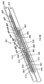
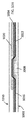
図1Aおよび1Bは、送達カテーテル、整列カテーテル、または受け取りカテーテルとしての使用のために好適なカテーテルの例証的変形例を描写する。具体的には、図1Aは、それを通る管腔(108)と、近位部分(104)と、遠位部分(106)とを備えている、カテーテル本体(102)を備えている、カテーテル(100)の上面図を描写する。図1Bは、部分的に透明であるように図示される、カテーテル本体(102)の遠位部分(106)を伴う、カテーテル(100)を描写する。カテーテル(100)の遠位部分(106)は、ポートまたは側面開口(110)と、1つ以上の整列要素(112)と、偏向器(114)とを備え得る。いくつかの変形例では、カテーテル本体(102)の遠位部分(106)はまた、カテーテル本体(102)の近位部分(104)に結合される、キャップ(118)を備え得るが、しかしながら、その必要はない。管腔(108)は、カテーテルの全長に延び得る、またはそうではないこともあることを理解されたい。加えて、いくつかの変形例では、キャップ(118)は、非外傷性であり得る、および/またはカテーテル(100)は、非外傷性先端を備え、血管系を通したカテーテルの前進の間、周囲組織への損傷を防止し得る。 FIGS. 1A and 1B depict exemplary variants of catheters suitable for use as delivery catheters, alignment catheters, or receiving catheters. Specifically, FIG. 1A comprises a catheter body (102) comprising a lumen (108) through it, a proximal portion (104) and a distal portion (106). The top view of (100) is drawn. FIG. 1B depicts a catheter (100) with a distal portion (106) of the catheter body (102), illustrated to be partially transparent. The distal portion (106) of the catheter (100) may comprise a port or side opening (110), one or more alignment elements (112), and a deflector (114). In some variants, the distal portion (106) of the catheter body (102) may also include a cap (118) that is attached to the proximal portion (104) of the catheter body (102), however. That is not needed. It should be understood that the lumen (108) may or may not extend to the full length of the catheter. In addition, in some variants, the cap (118) can be non-traumatic, and / or the catheter (100) has a non-traumatic tip and during the advancement of the catheter through the vasculature. It can prevent damage to surrounding tissues.
ポート(110)は、カテーテル本体(102)の長さに沿って(すなわち、カテーテル本体(102)の側面上に)位置し得、それを通してワイヤの通過を可能にするように定寸および構成され得る。ポート(110)は、ワイヤまたは別の要素が、カテーテル本体(102)の近位部分(104)から管腔(108)を通して、そこからポート(110)を通して、カテーテル本体(102)の外側の場所に前進させられ得るように、管腔(108)に流動的に結合され得る。いくつかの変形例では、ポート(110)は、カテーテルの無菌状態の維持を補助し得る、および/または管腔が詰まらないように防止し得る、薄膜で被覆され得る。膜は、使用時、ワイヤによって穿刺され、それを通したワイヤの通過を可能にし得る、または別様に、カテーテル(100)の使用の前もしくは間に除去され得る。円形として描写されるが、ポートは、卵形、正方形等を含む、任意の好適な形状を有し得る。複数のカテーテルが使用される、変形例では、各カテーテル上のポート(110)は、同一サイズおよび形状を有し得る、またはカテーテル上のポート(110)は、異なってもよい。ポート(110)は、任意の好適なサイズを有し得る。例えば、いくつかの変形例では、ポート(110)は、比較的に小さく、例えば、0.127mm(0.005インチ)直径、幅、または長さを有し得る一方、他の変形例では、ポート(110)は、比較的に大きく、例えば、7.62cm(3.00インチ)直径、幅、または長さを有し得る。いくつかの変形例では、送達カテーテル上のポート(110)は、受け取りカテーテル上のポート(110)より小さくてもよい(すなわち、より小さい直径、幅、または長さを有する)。送達カテーテル上のより小さいポート(110)および受け取りカテーテル上のより大きいポート(110)の利用は、ワイヤを位置付け、脈管壁に貫通および横断することを補助し得、ワイヤがポート(110)を通して受け取りカテーテルの管腔(108)の中に前進させられることをより容易にし得る。整列カテーテルが使用される、変形例では、整列カテーテルは、ポート(110)を有していないこともあることを理解されたい。 The port (110) can be located along the length of the catheter body (102) (ie, on the sides of the catheter body (102)) and is sized and configured to allow the passage of wires through it. obtain. The port (110) is where the wire or another element is located outside the catheter body (102) from the proximal portion (104) of the catheter body (102) through the lumen (108) and from there through the port (110). Can be fluidly coupled to the lumen (108) so that it can be advanced to. In some variants, the port (110) can be coated with a thin film that can help maintain the sterility of the catheter and / or prevent the lumen from becoming clogged. The membrane may be punctured by the wire during use and allow the wire to pass through it, or otherwise may be removed before or during the use of the catheter (100). Although depicted as circular, the port can have any suitable shape, including oval, square, and the like. In variants where multiple catheters are used, the ports (110) on each catheter may have the same size and shape, or the ports (110) on the catheter may be different. The port (110) can have any suitable size. For example, in some variants, the port (110) may be relatively small, eg, 0.127 mm (0.005 inch) in diameter, width, or length, while in other variants, The port (110) is relatively large and can have, for example, a 7.62 cm (3.00 inch) diameter, width, or length. In some variants, the port (110) on the delivery catheter may be smaller than the port (110) on the receiving catheter (ie, has a smaller diameter, width, or length). Utilization of a smaller port (110) on the delivery catheter and a larger port (110) on the receiving catheter can assist in positioning the wire and penetrating and traversing the vessel wall, with the wire passing through the port (110). It may be easier to advance into the lumen (108) of the receiving catheter. It should be appreciated that in variants where aligned catheters are used, aligned catheters may not have a port (110).
前述のように、遠位部分(106)は、ワイヤが進行する方向を改変し得る、傾斜偏向表面(116)を備えている、偏向器(114)を備え得、カテーテルがワイヤを送達または受け取るかどうかに応じて、ワイヤを管腔(108)からポート(110)にまたはその逆に誘導し得る。本明細書に説明されるカテーテルのいくつかの変形例では、偏向表面は、図1Aに描写されるように、直線または線形であり得る一方、他の変形例では、図11Aに描写されるように、湾曲され得る。加えて、送達カテーテルでは、偏向表面(116)はまた、ワイヤの位置付けを補助し、脈管壁の穿刺を促進し得る。本明細書に示されるように、偏向器(114)は、管腔(108)の遠位端に位置付けられ得、偏向表面(116)は、カテーテル本体(102)の近位部分(104)に向かって位置付けられる。偏向表面(116)は、相互および/または貫通のために意図される脈管壁に対するカテーテルの向きに応じて、正の傾き(すなわち、図1Bに描写されるように、カテーテルの近位端から遠位端に増加する)または負の傾き(すなわち、カテーテルの近位端から遠位端に減少する)を備え得る。送達および受け取りカテーテルが使用される、いくつかの変形例では、送達および受け取りカテーテルは、送達カテーテル内の偏向表面(116)が正の傾きを備え得る一方、受け取りカテーテル内の偏向表面(116)が負の傾きを備え得る、またはその逆であり得るように配列され得る。いくつかの変形例では、非使用時、送達および受け取りカテーテルの偏向表面の各々は、同一符号(例えば、両方とも正)を伴う傾きを備え得る。送達および受け取りカテーテルの偏向表面(116)の傾きは送達カテーテルから受け取りカテーテルへのワイヤの遷移を促進し得る。例えば、いくつかの変形例では、送達カテーテル内の偏向表面(116)の傾きは、受け取りカテーテル内の偏向表面(116)の傾きを上回る大きさを有し得る。他の変形例では、送達および受け取りカテーテル内の偏向表面(116)の傾きの大きさは、同一であり得る。いくつかの変形例では、偏向器および/または偏向表面は、カテーテルと一体的に形成され得ることを理解されたい。例えば、偏向器および/または偏向表面は、カテーテルの管腔の壁から形成され得る(例えば、管腔の遠位部分は、曲線または角度が付けられ得る)。換言すると、偏向器および/または偏向表面は、別個の要素である必要はない。 As mentioned above, the distal portion (106) may be equipped with a deflector (114), including a tilted deflecting surface (116) that can alter the direction in which the wire travels, and the catheter delivers or receives the wire. Depending on whether or not, the wire can be guided from the lumen (108) to the port (110) and vice versa. In some variants of the catheter described herein, the deflection surface can be straight or linear, as depicted in FIG. 1A, while in other variants, as depicted in FIG. 11A. Can be curved. In addition, in the delivery catheter, the deflection surface (116) can also assist in the positioning of the wire and facilitate puncture of the vessel wall. As shown herein, the deflector (114) can be located at the distal end of the lumen (108) and the deflection surface (116) is on the proximal portion (104) of the catheter body (102). Positioned towards. The deflection surface (116) is tilted positively (ie, from the proximal end of the catheter, as depicted in FIG. 1B), depending on the orientation of the catheter with respect to the vessel wall intended for mutual and / or penetration. It may have a (increasing to the distal end) or a negative tilt (ie, decreasing from the proximal end of the catheter to the distal end). In some variants in which the delivery and receiving catheters are used, the delivery and receiving catheters may have a deflection surface (116) within the delivery catheter while the deflection surface (116) within the delivery catheter may have a positive tilt. It can be arranged so that it can have a negative slope and vice versa. In some variants, when not in use, each of the deflection surfaces of the delivery and receiving catheters may have a tilt with the same sign (eg, both positive). The tilt of the deflection surface (116) of the delivery and receiving catheters can facilitate the transition of the wire from the delivery catheter to the receiving catheter. For example, in some modifications, the tilt of the deflection surface (116) within the delivery catheter may be greater than the tilt of the deflection surface (116) within the receiving catheter. In other variants, the magnitude of the tilt of the deflection surface (116) within the delivery and receiving catheters can be the same. It should be appreciated that in some variants the deflector and / or deflection surface can be formed integrally with the catheter. For example, the deflector and / or the deflection surface can be formed from the wall of the lumen of the catheter (eg, the distal portion of the lumen can be curved or angled). In other words, the deflector and / or the deflecting surface need not be separate elements.
送達カテーテル内の偏向表面(116)は、約20度〜約90度の出口角(すなわち、図2Bに描写されるように、ワイヤがポート(110)を通してカテーテル本体(102)から退出するにつれて、ワイヤとポート(110)に隣接するカテーテル本体(102)との間に形成される角度)をもたらす、傾きを備え得る。より具体的には、偏向表面(116)は、約30度、約40度、約50度、約60度、約70度、または約80度の出口角をもたらす、傾きを備え得る。以下により詳細に議論されるように、1つ以上の脈管壁を穿刺後、ワイヤが受け取りカテーテルに進入する、実施形態では、偏向表面(116)の傾きはまた、受け取りカテーテルに対するワイヤの位置付けを補助し、受け取りカテーテルの中への進入を促進し得る。 The deflection surface (116) within the delivery catheter has an exit angle of about 20 to about 90 degrees (ie, as depicted in FIG. 2B, as the wire exits the catheter body (102) through the port (110). It may have an inclination that results in the angle formed between the wire and the catheter body (102) adjacent to the port (110). More specifically, the deflected surface (116) can be tilted to provide an exit angle of about 30 degrees, about 40 degrees, about 50 degrees, about 60 degrees, about 70 degrees, or about 80 degrees. As discussed in more detail below, after puncturing one or more vessel walls, the wire enters the receiving catheter, in the embodiment, the tilt of the deflection surface (116) also positions the wire with respect to the receiving catheter. It can assist and facilitate entry into the receiving catheter.
いくつかの変形例では、偏向器はさらに、カテーテル内のポートと対応するように定寸および/または成形され得る、開口を備えている、筐体を備え得る。これらの変形例では、偏向器は、カテーテルの管腔内に固着して嵌合するように定寸される、形状(例えば、円筒形)を備え得、遠位部分内の偏向表面につながる、近位部分内の管腔を有し得る。これらの変形例では、偏向器は、筐体内の開口がカテーテル内のポートと整列させられ、偏向器内の開口およびカテーテル内のポートの両方を通したワイヤの通過を可能にするように、カテーテルの管腔内に位置付けられ、カテーテルに結合され得る。 In some variants, the deflector may further comprise a housing with an opening that can be sized and / or molded to correspond to a port in the catheter. In these variants, the deflector may have a shape (eg, a cylinder) that is sized to snap into and fit into the lumen of the catheter, leading to a deflecting surface within the distal portion. It may have a lumen within the proximal portion. In these variants, the deflector is a catheter such that the opening in the housing is aligned with the port in the catheter, allowing the wire to pass through both the opening in the deflector and the port in the catheter. It is located in the lumen of the catheter and can be attached to a catheter.
前述のように、カテーテル(100)の遠位部分(106)は、カテーテルを血管系内に整列させる、または別様に再位置付けすることを補助し得る、1つ以上の(例えば、2つ、3つ、4つ、5つ、6つ、7つ、8つ、またはそれを上回る)整列要素(112)を備え得る。例えば、いくつかの事例では、整列要素は、2つ以上のカテーテル(およびそれらとともに、2つ以上の血管)をより近接して接近させることに役立ち得る。他の事例では、整列要素は、1つ以上のカテーテルが別のカテーテルに対して適切な軸方向および/または回転整列にあることを確実にすることに役立ち得る。カテーテルおよび血管の適切な位置を確実にすることは、1つ以上の血管壁を通したワイヤの前進を促進することに役立ち得る。いくつかの変形例では、カテーテルは、別のカテーテル上の1つ以上の整列要素と相互作用する場合もある、またはそうではない場合もある、突出部、溝、平坦表面等の機械的整列要素を備え得る。加えて、または代替として、カテーテルは、磁気整列要素、すなわち、別のカテーテルの1つ以上の磁気構成要素と相互作用し得る、1つ以上の磁気構成要素を備え得る。さらに他の変形例では、カテーテルは、視覚的整列要素、例えば、ユーザが1つ以上のカテーテルを整列させることに役立ち得る、1つ以上のマーカを備え得る。本明細書に説明されるカテーテルの各々は、任意の整列要素または説明される整列要素の組み合わせを備え得ることを理解されたい。 As mentioned above, the distal portion (106) of the catheter (100) may assist in aligning or otherwise repositioning the catheter within the vasculature of one or more (eg, two, etc.). It may include (3, 4, 5, 6, 7, 8, or more) alignment elements (112). For example, in some cases, alignment elements can help bring two or more catheters (and along with them, two or more blood vessels) closer together. In other cases, the alignment element can help ensure that one or more catheters are in the proper axial and / or rotational alignment with respect to another catheter. Ensuring the proper location of catheters and vessels can help facilitate the advancement of wires through one or more vessel walls. In some variants, the catheter may or may not interact with one or more alignment elements on another catheter, mechanical alignment elements such as protrusions, grooves, flat surfaces, etc. Can be equipped. In addition, or as an alternative, the catheter may comprise a magnetic alignment element, i.e., one or more magnetic components capable of interacting with one or more magnetic components of another catheter. In yet another variant, the catheter may be equipped with a visual alignment element, eg, one or more markers that may help the user align one or more catheters. It should be appreciated that each of the catheters described herein may comprise any alignment element or combination of alignment elements described.
磁気整列要素が使用される、変形例では、磁気整列要素は、1つ以上の追加の要素(例えば、第2のカテーテルの1つ以上の部分)に引きつけられ、脈管内のカテーテルの位置付けまたは整列に役立ち得る。例えば、カテーテルは、カテーテルを別のカテーテルの1つ以上の部分に向かって誘引し、それによって、カテーテルをより近接して接近させ、カテーテルを回転に関し、および/または軸方向に関して向け、および/またはカテーテルの表面と別のカテーテルの1つ以上の表面または部分を一致させるように作用する、1つ以上の磁気整列要素を備え得る。 In a variant in which a magnetic alignment element is used, the magnetic alignment element is attracted to one or more additional elements (eg, one or more parts of the second catheter) to position or align the catheter within the vessel. Can help. For example, a catheter attracts a catheter towards one or more portions of another catheter, thereby bringing the catheter closer together and pointing the catheter in terms of rotation and / or axially and / or. It may comprise one or more magnetic alignment elements that act to align one or more surfaces or portions of another catheter with the surface of the catheter.
磁気整列要素は、任意の好適な磁石または磁気材料を備え得る。例えば、いくつかの変形例では、カテーテルは、1つ以上の希土類磁石(例えば、ネオジム磁石またはサマリウム−コバルト磁石)および/または1つ以上の選択的に活性化される電磁石を備え得る。カテーテルが複数の磁石を備えている、変形例では、これらの磁石は、1つ以上のアレイに群化され得る。これらの磁石アレイは、カテーテル(またはそれらの組み合わせ)の内側または外側に位置し得、カテーテルの長さに沿って任意の場所に位置付けられ得る。2つ以上のカテーテルが、磁石または磁石アレイを備えているとき、各磁石または磁石アレイは、別のカテーテルからの1つ以上の磁石または磁石アレイと整列するように構成または配列され得る。各磁石は、任意の好適な方法によって、カテーテル内または上に固定され得る。例えば、いくつかの変形例では、1つ以上の磁石は、カテーテル内に埋め込まれる、それに接着される、またはその中に摩擦嵌合され得る。各磁石は、任意の好適な直径(または非円形断面に関して、高さおよび/または幅)(例えば、約0.25mm(0.010インチ)〜約8mm(0.315インチ))または長さ(例えば、約0.25mm(0.001インチ)〜約25mm(0.984インチ))を有し得る。いくつかの変形例では、各磁石は、直径(または非円形断面に関して、高さおよび/または幅)約1.91mm(0.075インチ)、約2.03mm(0.080インチ)、約2.34mm(0.092インチ)、約2.79mm(0.110インチ)、もしくは同等物、または長さ約5mm(0.197インチ)、約10mm(0.394インチ)、約15mm(0.591インチ)、約20mm(0.787インチ)、もしくは同等物を有し得、任意の好適な距離(例えば、約1mm(0.039インチ)、約5mm(0.197インチ)等)だけ、隣り合った磁石から分離され得る。磁石サイズは、概して、カテーテルサイズに直接比例し得る(すなわち、磁石サイズは、カテーテルサイズの増加に伴って増加し得る)。いくつかの変形例では、アレイの磁石は、交互極性(例えば、各磁石が、任意の隣接する磁石と反対極性を有するであろう)、合致極性、またはそれらの組み合わせを有し得る。他の変形例では、カテーテルの1つ以上の部分は、磁気材料から作製され得る、および/または1つ以上の磁気粒子/材料とともに埋め込まれ得る。各磁石は、カテーテルの内側または外側への設置のための任意の好適な形状を有し得る。磁石は、円筒形、半円筒形、管形状、ボックス形状等であり得る。いくつかの変形例では、磁気整列要素は、2014年3月14日に出願され、「FISTULA FORMULATION DEVICES AND METHODS THEREFOR」と題された米国特許出願第14/214,503号、および/または2015年3月13日に出願され、「FISTULA FORMATION DEVICES AND METHODS THEREFOR」と題された米国特許出願第14/657,997号(そのそれぞれの内容は、参照することによってその全体として本明細書に組み込まれる)により詳細に説明されるように、Halbachアレイまたは集束磁石を備え得る。 The magnetic alignment element may comprise any suitable magnet or magnetic material. For example, in some variants, the catheter may comprise one or more rare earth magnets (eg, neodymium magnets or samarium-cobalt magnets) and / or one or more selectively activated electromagnets. In a variant where the catheter has multiple magnets, these magnets can be grouped into one or more arrays. These magnet arrays can be located inside or outside the catheter (or a combination thereof) and can be located anywhere along the length of the catheter. When two or more catheters are equipped with magnets or magnet arrays, each magnet or magnet array may be configured or arranged to align with one or more magnets or magnet arrays from another catheter. Each magnet can be anchored in or on the catheter by any suitable method. For example, in some variants, one or more magnets may be embedded in a catheter, adhered to it, or friction-fitted therein. Each magnet has any suitable diameter (or height and / or width with respect to a non-circular cross section) (eg, about 0.25 mm (0.010 inch) to about 8 mm (0.315 inch)) or length (. For example, it can have from about 0.25 mm (0.001 inch) to about 25 mm (0.984 inch). In some variants, each magnet has a diameter (or height and / or width with respect to a non-circular cross section) of about 1.91 mm (0.075 inches), about 2.03 mm (0.080 inches), and about 2. .34 mm (0.092 inches), about 2.79 mm (0.110 inches), or equivalent, or about 5 mm (0.197 inches) long, about 10 mm (0.394 inches), about 15 mm (0. 591 inches), about 20 mm (0.787 inches), or equivalent, and only at any suitable distance (eg, about 1 mm (0.039 inches), about 5 mm (0.197 inches), etc.), Can be separated from adjacent magnets. Magnet size can generally be directly proportional to catheter size (ie, magnet size can increase with increasing catheter size). In some variants, the magnets in the array may have alternating polarities (eg, each magnet will have the opposite polarity to any adjacent magnet), matching polarity, or a combination thereof. In another variant, one or more parts of the catheter can be made from magnetic material and / or embedded with one or more magnetic particles / material. Each magnet can have any suitable shape for installation inside or outside the catheter. The magnet can be cylindrical, semi-cylindrical, tube-shaped, box-shaped, or the like. In some variations, the magnetic alignment element was filed on March 14, 2014, and is entitled "FISTULA FORMULATION DEVICES AND METHODS THE REFOR", US Patent Application No. 14 / 214,503, and / or 2015. U.S. Patent Application Nos. 14 / 657,997, filed March 13, entitled "FISTULA FORMATION DEVICES AND METHODS THE REFOR", the contents of which are incorporated herein by reference in their entirety. ) May be equipped with a Halbach array or focusing magnets.
カテーテル本体(102)は、任意の好適な断面形状を備え得る。いくつかの変形例では、カテーテル本体は、円形断面形状(図1Aおよび1Bに示されるように)、正方形断面形状(図3Aに示されるように)、長方形断面形状、それらの組み合わせ等を備え得る。例えば、いくつかの事例では、カテーテル本体は、近位部分における第1の断面形状(例えば、円形)と、遠位部分または1つ以上の整列要素を備えている部分(遠位部分と異なる場合)における第2の断面形状(例えば、正方形)とを有し得る。例えば、カテーテルが平坦整列表面を備えているように、1つ以上の整列要素を備えている部分に正方形断面形状を備えている、カテーテル本体を利用することが望ましくあり得る。整列要素が磁石を備えている、変形例では、平坦磁気表面は、側方磁気接合力が、発生させられ、整列トルクに変換され、それによって、カテーテルをより容易に回転整列させることを可能にする。加えて、平坦整列表面の使用は、カテーテルを一緒により近づけ、介在脈管壁をより圧縮し、より大きい平坦面積を2つのカテーテル間に作成し得、その全ては、脈管壁を通して、随意に、別のカテーテルの中に、ワイヤをより容易に貫通および前進させ得る。 The catheter body (102) may have any suitable cross-sectional shape. In some variants, the catheter body may comprise a circular cross-sectional shape (as shown in FIGS. 1A and 1B), a square cross-sectional shape (as shown in FIG. 3A), a rectangular cross-sectional shape, a combination thereof, and the like. .. For example, in some cases, the catheter body differs from the first cross-sectional shape (eg, circular) in the proximal portion and the distal portion or portion with one or more alignment elements (eg, the distal portion). ) Can have a second cross-sectional shape (eg, a square). For example, it may be desirable to utilize a catheter body that has a square cross-sectional shape in the portion with one or more alignment elements, just as the catheter has a flat alignment surface. In a variant where the alignment element is equipped with a magnet, the flat magnetic surface allows lateral magnetic bonding forces to be generated and converted into alignment torque, thereby allowing the catheter to be more easily rotationally aligned. do. In addition, the use of flat aligned surfaces can bring the catheters closer together, compress the intervening vessel wall more, and create a larger flat area between the two catheters, all optionally through the vessel wall. , The wire can be more easily penetrated and advanced into another catheter.
いくつかの事例では、ワイヤを利用して、本明細書に説明されるカテーテルを血管系内の標的組織に前進させることを補助することが望ましくあり得る。故に、いくつかの変形例では、本明細書に説明されるカテーテルは、血管系を通してガイドワイヤに沿って前進し、かつ瘻孔形成において使用され得る、ワイヤを送達または受け取るように構成され得る。例えば、図3Aおよび3Bは、カテーテル(300)のそのような変形例の斜視図および例証的断面図を描写する。そこに示されるように、カテーテル(300)は、カテーテル本体(302)と、偏向表面(306)を備えている、偏向器(304)と、第1の整列要素(308)と、第2の整列要素(312)と、ポート(310)と、遠位開口部(316)とを備え得る。本変形例では、カテーテル本体(302)は、図1Aおよび1Bに関して上で説明される管腔(108)に類似する、それを通る第1の管腔(314)と、カテーテル本体(302)のハンドルまたは近位部分内の近位開口部(図示せず)および遠位開口部(316)に流動的に結合し得る、それを通る第2の管腔(318)とを備え得る。第1および第2の整列要素(308、312)ならびに偏向器(304)は、第1の管腔(314)内に位置付けられ得、ガイドワイヤ(320)は、第2の管腔(318)内に位置付けられ得る。カテーテル(300)は、個別的な偏向器(304)とともに描写されるが、いくつかの変形例では、偏向表面(306)は、カテーテル(300)の壁から形成され得る。 In some cases, it may be desirable to utilize wires to assist in advancing the catheter described herein to the target tissue within the vascular system. Thus, in some variants, the catheter described herein can be configured to deliver or receive a wire that advances along a guide wire through the vascular system and can be used in fistula formation. For example, FIGS. 3A and 3B depict perspective views and exemplary cross-sectional views of such variants of the catheter (300). As shown therein, the catheter (300) comprises a catheter body (302), a deflector (304) comprising a deflection surface (306), a first alignment element (308), and a second. It may include an alignment element (312), a port (310), and a distal opening (316). In this variant, the catheter body (302) is similar to the lumen (108) described above with respect to FIGS. 1A and 1B, with a first lumen (314) passing through it and a catheter body (302). It may be equipped with a second lumen (318) through which it can fluidly bind to a proximal opening (not shown) and a distal opening (316) within the handle or proximal portion. The first and second alignment elements (308, 312) and deflector (304) can be positioned within the first lumen (314) and the guide wire (320) is the second lumen (318). Can be positioned within. The catheter (300) is depicted with a separate deflector (304), but in some variants the deflection surface (306) can be formed from the wall of the catheter (300).
カテーテル(300)は、第1の管腔(314)および第2の管腔(318)とともに描写されるが、他の変形例では、カテーテル(300)は、両ガイドワイヤがカテーテルを血管系を通して前進させることを補助するために利用され得る、単一管腔と、脈管に接続するために使用され得る、ワイヤとを備え得ることを理解されたい。例えば、本実施形態では、単一管腔は、近位開口部、遠位開口部、およびポートに流動的に結合し得、1つ以上の整列要素および偏向器は、ガイドワイヤが整列要素および偏向器の真下またはそれに隣接して管腔を通して通過し得るように、サイズを決定され、成形され、管腔内に位置付けられ得る。例えば、整列要素は、カテーテルの管腔の直径より小さくてもよく(例えば、より小さい直径、高さ、体積を備えている)、ワイヤが整列要素の周囲またはそれに隣接して通過し得るように位置付けられ得る(例えば、管腔の上部、底部、または両側において、カテーテルの内部表面に対して位置付けられ、および/またはカテーテル壁内に埋め込まれ得る)。他の実施形態では、カテーテルは、単一管腔を備え得、1つ以上の整列要素および偏向器は、それを通る管腔を備え、カテーテルを通した遠位開口部へのガイドワイヤの通路を収容し得る。カテーテルが単一管腔を備えている、さらに他の実施形態では、カテーテルは、要素の真下または周囲のガイドワイヤの通過を可能にするためにサイズを決定され、成形され、および/または位置付けられる、要素と、それを通してガイドワイヤの通過を可能にするためのそれを通る管腔を備えている、要素の組み合わせを備え得る。例えば、整列要素は、ガイドワイヤが、整列要素の真下またはそれに隣接して通過し得る一方、偏向器が、ガイドワイヤが偏向器を通して通過し得るように、それを通る管腔を備え得るように、またはその逆であるように、サイズを決定され、成形され、および/または管腔内に位置付けられ得る。 The catheter (300) is depicted with the first lumen (314) and the second lumen (318), but in another variant, the catheter (300) has both guide wires passing the catheter through the vasculature. It should be understood that a single lumen, which can be used to assist in advancing, and a wire, which can be used to connect to a vessel, can be provided. For example, in this embodiment, a single lumen may be fluidly coupled to a proximal opening, a distal opening, and a port, and one or more alignment elements and deflectors may have a guidewire alignment element and It can be sized, shaped and positioned within the lumen so that it can pass through the lumen directly below or adjacent to the deflector. For example, the alignment element may be smaller than the diameter of the catheter's lumen (eg, having a smaller diameter, height, volume) so that the wire can pass around or adjacent to the alignment element. Can be positioned (eg, at the top, bottom, or both sides of the lumen, can be positioned relative to the inner surface of the catheter and / or implanted within the catheter wall). In other embodiments, the catheter may comprise a single lumen, one or more alignment elements and deflectors comprising a lumen through which the guidewire passage to the distal opening through the catheter. Can be accommodated. In yet other embodiments where the catheter comprises a single lumen, the catheter is sized, shaped, and / or positioned to allow passage of guide wires beneath or around the element. It may be equipped with a combination of elements, which comprises an element and a lumen through it to allow the passage of a guide wire through it. For example, the alignment element may include a lumen through which the guide wire may pass beneath or adjacent to the alignment element, while the deflector may pass through the deflector. , Or vice versa, can be sized, molded, and / or positioned within the lumen.
いくつかの変形例では、カテーテルは、血管系を通してカテーテルを前進させるためのガイドワイヤと、2つの脈管を接続するために使用され得る、ガイドワイヤの両方のために利用され得る、単一管腔を備え得る。例えば、図4Aおよび4Bは、それぞれ、カテーテル本体(402)を備えている、それを通る単一管腔(414)と、偏向表面(406)を備えている、偏向器(404)と、第1の整列要素(408)と、第2の整列要素(412)と、ポート(410)と、遠位開口部(図示せず)とを備えている、カテーテル(400)の変形例の断面図および斜視断面図を描写する。偏向器(404)および整列要素(408、412)は、ガイドワイヤが、偏向器(404)および整列要素(408、412)の周囲またはそれを通して通過すること等によって、カテーテルを通して通過し得るように構成され得る。図4Aおよび4Bに示される変形例では、第1の整列要素(408)は、ガイドワイヤ(420)が、その真下またはそれに隣接して通過し得る一方、偏向器(404)および第2の整列要素(412)がそれぞれ、それを通してガイドワイヤ(420)が、進行し、遠位開口部に到達し得る、管腔または開口部(それぞれ、422、424)を備え得るように、サイズを決定され、管腔(414)内に位置付けられ得る。さらに明確にするために、図4Cは、カテーテル(400)から除去された図4Aおよび4Bに示される偏向器(404)を描写する。別個の要素として図4Cに描写されるが、いくつかの変形例では、偏向器(404)および/または偏向表面(406)は、カテーテル(400)の壁から形成され得る。 In some variants, the catheter is a single tube, which can be used for both a guide wire to advance the catheter through the vasculature and a guide wire, which can be used to connect two vessels. May have a lumen. For example, FIGS. 4A and 4B show a single lumen (414) through which a catheter body (402) and a deflector (404) with a deflection surface (406), respectively. Cross-sectional view of a variant of the catheter (400) comprising one alignment element (408), a second alignment element (412), a port (410), and a distal opening (not shown). And draw a perspective cross section. The deflector (404) and alignment element (408, 412) allow the guide wire to pass through the catheter, such as by passing around or through the deflector (404) and alignment element (408, 412). Can be configured. In the variants shown in FIGS. 4A and 4B, the first alignment element (408) allows the guide wire (420) to pass beneath or adjacent to it, while the deflector (404) and second alignment. Each element (412) is sized so that the guide wire (420) through it can be provided with a lumen or opening (422, 424, respectively) through which the guide wire (420) can travel and reach the distal opening. , Can be located within the lumen (414). To further clarify, FIG. 4C depicts the deflector (404) shown in FIGS. 4A and 4B removed from the catheter (400). Although depicted in FIG. 4C as a separate element, in some variants the deflector (404) and / or deflection surface (406) can be formed from the wall of the catheter (400).
(1.送達カテーテル)
図2Aおよび2Bは、ワイヤが矢印の方向に(例えば、カテーテルの遠位端の近位から)、カテーテルの管腔(図2A)を通してカテーテル本体内のポート(図2B)に前進させられるにつれた送達カテーテルの変形例の例証的断面図を描写する。そこに示されるように、送達カテーテル(200)は、それを通る管腔(214)を備えている、カテーテル本体(202)と、偏向表面(206)を備えている、偏向器(204)と、第1の整列要素(208)と、第2の整列要素(212)と、ポート(210)とを備え得る。第1の整列要素(210)は、ポート(210)および偏向器(204)の近位に位置する一方、第2の整列要素(212)は、ポート(210)および偏向器(204)の遠位に位置する。換言すると、偏向器(204)は、第1の整列要素(208)と第2の整列要素(212)との間に位置する。図2Aおよび2Bに示される実施形態では、第1および第2の整列要素(208、212)は、上で説明されるように、カテーテル本体(202)の管腔(214)内に位置付けられる、磁石アレイを備えているが、しかしながら、これは、当てはまる必要はない。整列要素(208、212)は、上で説明される整列要素のいずれかを備え得る。第1の整列要素(208)は、示されるように、それを通る管腔を備え、整列要素(208)を通るワイヤ(216)の通路を収容し得る。さらに、偏向器(204)は、別個の要素として描写されるが、いくつかの変形例では、そうである必要はなく、偏向器(204)および偏向表面(206)は、カテーテルの壁から形成され得る。
(1. Delivery catheter)
2A and 2B were taken as the wire was advanced in the direction of the arrow (eg, proximal to the distal end of the catheter) through the lumen of the catheter (FIG. 2A) to a port within the catheter body (FIG. 2B). Illustrative cross-sectional views of variants of delivery catheters are depicted. As shown therein, the delivery catheter (200) has a catheter body (202) with a lumen (214) through it and a deflector (204) with a deflection surface (206). , A first alignment element (208), a second alignment element (212), and a port (210) may be provided. The first alignment element (210) is located proximal to the port (210) and deflector (204), while the second alignment element (212) is far from the port (210) and deflector (204). Located in the rank. In other words, the deflector (204) is located between the first alignment element (208) and the second alignment element (212). In the embodiments shown in FIGS. 2A and 2B, the first and second alignment elements (208, 212) are positioned within the lumen (214) of the catheter body (202) as described above. It has a magnet array, however, this does not have to be the case. The alignment element (208, 212) may comprise any of the alignment elements described above. The first alignment element (208), as shown, comprises a lumen through it and may accommodate a passage of wire (216) through the alignment element (208). In addition, the deflector (204) is depicted as a separate element, but in some variants it does not have to be, and the deflector (204) and deflection surface (206) are formed from the wall of the catheter. Can be done.
使用時、ワイヤ(216)は、ワイヤ(216)が偏向器(204)の偏向表面(206)に接触し得るように、矢印によって示されるように、カテーテル(200)の近位端から偏向器(204)およびカテーテルの遠位端に向かって前進させられ得る。偏向表面(206)は、ワイヤ(216)がさらに遠位に前進することを防止し得、上で説明されるように、ワイヤ(216)が管腔(214)から出口角(218)においてポート(210)を通して退出するように、その経路を改変し得る。ワイヤ(216)は、次いで、脈管壁を通して、随意に、受け取りカテーテルの中に前進させられ得る。ワイヤ(216)は、丸みを帯びた遠位先端(220)を伴って描写されるが、これは、当てはまる必要はない。いくつかの変形例では、ワイヤ(216)は、開口部を組織内に穿刺または作成するように構成される、遠位先端(220)(例えば、鋭い遠位先端または同等物)を備え得る。いくつかの事例では、ワイヤ(216)は、ワイヤの再指向を補助し得る、屈曲される、遠位先端(220)を備え得る。 In use, the wire (216) is deflected from the proximal end of the catheter (200) so that the wire (216) can contact the deflecting surface (206) of the deflector (204), as indicated by the arrow. (204) and can be advanced towards the distal end of the catheter. The deflecting surface (206) can prevent the wire (216) from advancing further distally, and as explained above, the wire (216) is ported from the lumen (214) to the exit angle (218). The route may be modified to exit through (210). The wire (216) can then be optionally advanced into the receiving catheter through the vessel wall. The wire (216) is depicted with a rounded distal tip (220), but this does not have to be the case. In some variants, the wire (216) may comprise a distal tip (220) (eg, a sharp distal tip or equivalent) configured to puncture or create an opening in the tissue. In some cases, the wire (216) may comprise a bent, distal tip (220) that may assist in redirection of the wire.
(2.受け取りカテーテル)
図5Aおよび5Bは、それぞれ、受け取りカテーテルの断面および斜視断面図を描写する。そこに示されるように、受け取りカテーテル(500)は、それを通る管腔を備えている、カテーテル本体(502)と、偏向表面(506)を備えている、偏向器(504)と、ポート(510)と、第1の整列要素(508)と、第2の整列要素(512)と、導糸管または漏斗要素(516)とを備え得る。本変形例では、第1の整列要素(508)は、ポート(510)を通してカテーテル本体(502)に進入し、偏向器(504)の偏向表面(506)によって漏斗要素(516)の中に、次いで、第1の整列要素(508)の中に再指向された後にワイヤが通過するためのそれを通る管腔(518)を備え得る。いくつかの変形例では、偏向器(504)、偏向表面(506)、および/または漏斗要素(516)は、カテーテルの壁から形成され得る(例えば、カテーテル本体の一部であり得る)。
(2. Receiving catheter)
5A and 5B depict cross-sections and perspective cross-sections of the receiving catheter, respectively. As shown therein, the receiving catheter (500) has a catheter body (502) with a lumen through it, a deflector (504) with a deflection surface (506), and a port ( 510), a first alignment element (508), a second alignment element (512), and a thread tube or funnel element (516) may be provided. In this variant, the first alignment element (508) enters the catheter body (502) through the port (510) and into the funnel element (516) by the deflection surface (506) of the deflector (504). It may then be provided with a lumen (518) through which the wire passes after being reoriented into the first alignment element (508). In some variants, the deflector (504), deflection surface (506), and / or funnel element (516) can be formed from the wall of the catheter (eg, it can be part of the catheter body).
漏斗要素(516)は、偏向表面(506)によって偏向されると、ワイヤの遠位先端を第1の整列要素(508)の管腔(518)の中に指向するために使用され得る。加えて、漏斗要素(516)は、偏向器(504)および第1の整列要素(508)流動的に結合し得る。漏斗要素(516)は、管腔を備えている、円錐形状または円錐台形状本体を備え得る。管腔は、管腔が近位に減少する直径を有するように、漏斗要素(516)の近位端における第1のより小さい直径と、漏斗要素(516)のの遠位端における第2のより大きい直径とを有し得る。いくつかの変形例では、漏斗要素(516)および第1の整列要素(508)の管腔は、同一サイズならびに形状であり得、および/または漏斗要素(516)および第1の整列要素(508)は、その管腔が整列するように位置付けられ得る。漏斗要素(516)は、直接、第1の整列要素(508)に隣接し得る、またはそうではないこともある。いくつかの変形例では、第1の整列要素(508)は、それを通る管腔を備えている代わりに、カテーテル本体(502)の管腔を通して第1の整列要素(508)の真下またはそれに隣接してワイヤの通過を可能にするようにサイズを決定され、成形され、および位置付けられ得る。これらの変形例では、漏斗要素(516)は、偏向器(504)を漏斗要素(516)の近位のカテーテル管腔の部分に流動的に結合し得る。いくつかの変形例では、受け取りカテーテルは、導糸管または漏斗要素を備えていないこともある。 The funnel element (516), when deflected by the deflection surface (506), can be used to direct the distal tip of the wire into the lumen (518) of the first alignment element (508). In addition, the funnel element (516) can be fluidly coupled to the deflector (504) and the first alignment element (508). The funnel element (516) may comprise a conical or truncated cone-shaped body with a lumen. The lumen has a first smaller diameter at the proximal end of the funnel element (516) and a second smaller diameter at the distal end of the funnel element (516) so that the lumen has a diameter that decreases proximally. Can have a larger diameter. In some variants, the lumens of the funnel element (516) and the first alignment element (508) can be of the same size and shape, and / or the funnel element (516) and the first alignment element (508). ) Can be positioned so that the lumens are aligned. The funnel element (516) may or may not be directly adjacent to the first alignment element (508). In some variants, the first alignment element (508) is either directly below or below the first alignment element (508) through the lumen of the catheter body (502) instead of having a lumen through it. Adjacent can be sized, molded, and positioned to allow the passage of wires. In these variants, the funnel element (516) may fluidly connect the deflector (504) to a portion of the catheter lumen proximal to the funnel element (516). In some variants, the receiving catheter may not be equipped with a thread tube or funnel element.
(3.送達および受け取りカテーテルの使用)
前述のように、本明細書に説明される送達および受け取りカテーテルは、互いに整列する、または別様に相互の位置に影響を及ぼすように構成され得る。例えば、図6Aおよび6Bは、それぞれ、ワイヤ(620)と併用する際の送達カテーテル(602)と、受け取りカテーテル(650)とを備えている、システム(600)の側面断面図および上部斜視断面図を描写する(脈管壁は、明確にするために省略されている)。そこに示されるように、送達カテーテル(602)は、それを通る管腔(614)を備えている、カテーテル本体(616)と、偏向表面(606)を備えている、偏向器(604)と、それを通る管腔(618)を備えている、第1の整列要素(608)と、ポート(610)と、第2の整列要素(612)とを備え得る。受け取りカテーテル(650)は、カテーテル本体(652)と、偏向表面(656)を備えている、偏向器(654)と、それを通る管腔(664)を備えている、第1の整列要素(658)と、ポート(660)と、漏斗要素(666)と、第2の整列要素(662)とを備え得る。前述のように、いくつかの変形例では、偏向器、偏向表面、および/または漏斗要素は、カテーテル本体と一体的に形成され得る。
(3. Use of delivery and receiving catheters)
As mentioned above, the delivery and receiving catheters described herein can be configured to align with each other or otherwise influence each other's position. For example, FIGS. 6A and 6B are side and upper perspective sectional views of a system (600) comprising a delivery catheter (602) and a receiving catheter (650) for use with the wire (620), respectively. (The vessel wall is omitted for clarity). As shown therein, the delivery catheter (602) has a catheter body (616) with a lumen (614) through it and a deflector (604) with a deflection surface (606). , A first alignment element (608) comprising a lumen (618) through it, a port (610), and a second alignment element (612). The receiving catheter (650) comprises a catheter body (652), a deflector (654) comprising a deflection surface (656), and a first alignment element (664) through which the lumen (664) is provided. 658), a port (660), a funnel element (666), and a second alignment element (662) may be provided. As mentioned above, in some variants, the deflector, deflection surface, and / or funnel element may be formed integrally with the catheter body.
システムはまた、脈管壁に貫通するために使用され得る、ワイヤ(620)を備え得る。いくつかの変形例では、ワイヤ(620)は、孔を組織内に貫通または別様に形成するように構成される、遠位先端を備え得る。いくつかの事例では、ワイヤ(620)は、ガイドワイヤであり得る。送達カテーテル(602)および/または受け取りカテーテル(650)が、ガイドワイヤを利用して、血管系を通して標的場所に前進させるように構成され得る、変形例では、システムは、送達または受け取りカテーテルのいずれかを標的場所に前進させるための第1のガイドワイヤと、脈管壁に貫通するための第2のワイヤ(620)とを備え得る。さらに他の変形例では、同一ワイヤ(620)が、送達カテーテルを標的場所に前進させ、かつ脈管壁に貫通するために使用され得る。さらに他の変形例では、システムは、送達カテーテルを標的場所に前進させるための第1のガイドワイヤと、受け取りカテーテルを対応する標的場所に前進させるための第2のガイドワイヤと、脈管壁に貫通するための第3のワイヤ(620)とを備え得る。 The system may also be equipped with a wire (620) that can be used to penetrate the vessel wall. In some variants, the wire (620) may comprise a distal tip that is configured to penetrate or otherwise form a hole in the tissue. In some cases, the wire (620) can be a guide wire. In a variant, the delivery catheter (602) and / or the receiving catheter (650) may be configured to advance to a target location through the vasculature using a guide wire, the system is either a delivery or receiving catheter. Can be equipped with a first guide wire for advancing to the target location and a second wire (620) for penetrating the vessel wall. In yet another variant, the same wire (620) can be used to advance the delivery catheter to the target location and penetrate the vessel wall. In yet another variant, the system has a first guide wire for advancing the delivery catheter to the target location, a second guide wire for advancing the receiving catheter to the corresponding target location, and a vessel wall. It may be equipped with a third wire (620) for penetrating.
使用時、送達カテーテル(602)および受け取りカテーテル(650)は、血管系を通して、それぞれ、第1の脈管および第2の脈管または空洞内の対応する標的場所に前進させられ得る。送達カテーテル(602)および受け取りカテーテル(650)が、相互の近傍に位置すると、カテーテルの整列要素が、カテーテルを軸方向に関し、および/または回転に関して整列させるために使用され得る。いくつかの変形例では、送達カテーテル(602)および受け取りカテーテル(650)は、逆平行構成において軸方向に整列させられるように構成され得る。例えば、送達カテーテル(602)上の第1の整列要素(608)は、受け取りカテーテル(650)上の第2の整列要素(662)と一致する、それを誘引する、または別様にそれと相互作用するように構成され得る一方、送達カテーテル(602)上の第2の整列要素(612)は、受け取りカテーテル(650)上の第1の整列要素(658)と一致する、それを誘引する、または別様にそれと相互作用し、送達および受け取りカテーテル(602、650)を通してワイヤまたはガイドワイヤ経路を形成するように構成され得る。他の変形例では、送達カテーテル(602)および受け取りカテーテル(650)は、平行構成において軸方向に整列させられるように構成され得る。例えば、送達カテーテル上の第1の整列要素は、受け取りカテーテル上の第1の整列要素と一致する、それを誘引する、または別様にそれと相互作用するように構成され得、送達カテーテル上の第2の整列要素は、受け取りカテーテル上の第2の整列要素と一致する、それを誘引する、または別様にそれと相互作用するように構成され得る。いくつかの変形例では、送達カテーテル(602)および受け取りカテーテル(650)は、それらが平行または逆平行構成のいずれかにおいて整列させられ得るように構成され得る。 In use, the delivery catheter (602) and the receiving catheter (650) can be advanced through the vasculature to the corresponding target location within the first and second vessels or cavities, respectively. When the delivery catheter (602) and the receiving catheter (650) are located in close proximity to each other, the alignment elements of the catheter can be used to align the catheter axially and / or rotationally. In some variants, the delivery catheter (602) and the receiving catheter (650) may be configured to be axially aligned in an antiparallel configuration. For example, the first alignment element (608) on the delivery catheter (602) coincides with, attracts, or otherwise interacts with the second alignment element (662) on the receiving catheter (650). The second alignment element (612) on the delivery catheter (602) coincides with, attracts, or attracts the first alignment element (658) on the receiving catheter (650). It may be configured to otherwise interact with it to form a wire or guide wire path through the delivery and receiving catheters (602, 650). In another variant, the delivery catheter (602) and the receiving catheter (650) may be configured to be axially aligned in a parallel configuration. For example, the first alignment element on the delivery catheter can be configured to match, attract, or otherwise interact with the first alignment element on the receiving catheter, the first on the delivery catheter. The alignment element of 2 may be configured to match, attract, or otherwise interact with the second alignment element on the receiving catheter. In some variants, the delivery catheter (602) and the receiving catheter (650) may be configured such that they can be aligned in either a parallel or antiparallel configuration.
加えて、送達カテーテル(602)および受け取りカテーテル(650)(例えば、整列要素)は、カテーテルの遠位端とは対照的に、送達および受け取りカテーテルを縦に整列させるように構成され得る。整列カテーテルが、受け取りカテーテルの代わりに使用される(すなわち、ワイヤ(620)が、送達カテーテルから退出した後、別のカテーテルの中に前進させられない)、変形例では、整列カテーテルは、受け取りカテーテルに関して説明される整列要素構成のいずれかを備え得る。さらに、整列要素は、磁石アレイとして描写されるが、それらは、上で説明される整列要素のいずれかであり得ることを理解されたい。加えて、送達および受け取りカテーテル(602、650)の両方の各々は、2つの整列要素を伴って描写されるが、それらは、上で説明されるように、任意の好適な数の整列要素を備え得る。 In addition, the delivery catheter (602) and the receiving catheter (650) (eg, alignment element) can be configured to align the delivery and receiving catheters vertically as opposed to the distal end of the catheter. In a variant, the aligned catheter is used in place of the receiving catheter (ie, the wire (620) cannot be advanced into another catheter after exiting the delivery catheter). It may have any of the alignment element configurations described with respect to. Further, although the alignment elements are depicted as magnet arrays, it should be understood that they can be any of the alignment elements described above. In addition, each of the delivery and receiving catheters (602, 650) is depicted with two alignment elements, which, as described above, have any suitable number of alignment elements. Can be prepared.
送達および受け取りカテーテル(602、650)が整列させられると、それらは、ワイヤが、送達カテーテルから、1つ以上の脈管壁を通して、受け取りカテーテルの中に前進させられ得るように構成され得る。より具体的には、ワイヤ(620)は、送達カテーテル(602)の近位端から、送達カテーテル本体(616)内の管腔(614)および送達カテーテル(602)内の第1の整列要素(608)の管腔(618)を通して、偏向器(604)上の偏向表面(606)に前進させられ得る。偏向表面(606)は、次いで、脈管壁に貫通し、続いて、受け取りカテーテル(650)のポート(660)に進入するために適切な出口角において、ポート(610)を通して送達カテーテル(602)から退出するように、ワイヤ(620)の方向を改変し得る。ワイヤ(620)が1つ以上の脈管壁に貫通した後、ポート(660)を通して受け取りカテーテル(650)に進入し得る。ワイヤ(620)が前進させられ続けるにつれて、偏向器(654)の偏向表面(656)に到達し得、これは、次いで、漏斗要素(666)および受け取りカテーテル(650)内の第1の整列要素(658)の管腔(664)に進入するように、ワイヤ(620)の方向を改変し得る。前述のように、送達および受け取りカテーテル(602、650)の両方における偏向器(604、654)の偏向表面(606、656)は、送達カテーテル(602)から受け取りカテーテル(650)へのワイヤ(620)の遷移を促進し、ワイヤ(620)を送達カテーテル管腔(614)から受け取りカテーテル(650)内の管腔に誘導するように構成され得る。 Once the delivery and receiving catheters (602, 650) are aligned, they can be configured such that the wire can be advanced from the delivery catheter through one or more vascular walls into the receiving catheter. More specifically, the wire (620) is from the proximal end of the delivery catheter (602) to the lumen (614) within the delivery catheter body (616) and the first alignment element (602) within the delivery catheter (602). It can be advanced to the deflection surface (606) on the deflector (604) through the lumen (618) of 608). The deflection surface (606) then penetrates the vessel wall and subsequently through the port (610) at the appropriate exit angle to enter the port (660) of the receiving catheter (650). The orientation of the wire (620) can be modified to exit from. After the wire (620) has penetrated one or more vessel walls, it can enter the receiving catheter (650) through the port (660). As the wire (620) continues to be advanced, it may reach the deflection surface (656) of the deflector (654), which in turn is the first alignment element within the funnel element (666) and the receiving catheter (650). The orientation of the wire (620) can be modified to enter the lumen (664) of (658). As mentioned above, the deflection surface (606, 656) of the deflector (604, 654) in both the delivery and receiving catheters (602, 650) is the wire (620) from the delivery catheter (602) to the receiving catheter (650). ) Can be configured to facilitate the transition and guide the wire (620) from the delivery catheter lumen (614) to the lumen within the receiving catheter (650).
(B.3カテーテルシステム)
前述のように、本明細書に説明されるシステムは、閉塞された脈管をバイパスするために使用され得る。これらのシステムは、閉塞された脈管管腔内における閉塞の第1の側への前進のための第1のカテーテルと、閉塞またはその近傍の場所への閉塞された脈管の外側における前進のための第2のカテーテルと、閉塞された脈管管腔内における閉塞の第2の反対側への前進のための第3のカテーテルとを備え得る。いくつかの変形例では、第1のカテーテルは、上で説明される送達カテーテルのいずれかであり得、第3のカテーテルは、上で説明される受け取りカテーテルのいずれかであり得る。第2のカテーテルは、閉塞の周囲において第1の脈管の外側でワイヤを前進させるために、ワイヤの受け取りおよび送達の両方のために使用される、バイパスカテーテルであり得る。例えば、第2のカテーテルは、送達カテーテルから脈管壁を通して展開された後、ワイヤを受け取り、ワイヤを格納または別様に移送し、閉塞された脈管内の閉塞を回避またはバイパスし、閉塞の反対側の閉塞された脈管内においてワイヤを受け取りカテーテルに送達するように構成され得る。
(B.3 Catheter system)
As mentioned above, the system described herein can be used to bypass an obstructed vessel. These systems include a first catheter for advancing the obstruction to the first side within the obstructed vascular lumen and advancing outside the obstructed vessel to or near the obstruction. A second catheter for the purpose and a third catheter for the second contralateral advancement of the occlusion within the occluded vascular lumen may be provided. In some variants, the first catheter can be any of the delivery catheters described above and the third catheter can be any of the receiving catheters described above. The second catheter can be a bypass catheter used for both receiving and delivering the wire to advance the wire outside the first vessel around the occlusion. For example, the second catheter, after being deployed from the delivery catheter through the vessel wall, receives the wire, stores or otherwise transfers the wire, avoids or bypasses the obstruction within the obstructed vessel, and opposes the obstruction. It may be configured to receive the wire and deliver it to the catheter within the side obstructed vessel.
図7Aおよび7Bは、バイパスカテーテルとしての使用のために好適なカテーテルの例証的変形例を描写する。具体的には、図7Aは、それを通る管腔(708)を備えている、カテーテル本体(702)と、近位部分(704)と、遠位部分(706)とを備えている、カテーテル(700)の上面図を描写する。図7Bは、部分的に透明であるように図示されるカテーテル本体(702の)遠位部分(706)を伴う、カテーテル(700)の図を描写する。カテーテル(700)の遠位部分(706)は、第1のポートまたは側面開口(710)と、第2のポートまたは側面開口(712)と、第1の整列要素(714)と、第2の整列要素(716)と、第1の偏向器(718)と、第2の偏向器(720)とを備え得る。いくつかの変形例では、カテーテル本体は、管腔(708)を第1および第2のポート(710、712)間において円周方向に包囲し得る。これらの変形例のいくつかでは、カテーテル(700)はさらに、以下により詳細に説明されるように、細隙(722)を第1および第2のポート(710、712)間に備え得、それを通してワイヤが、通過し、受け取りカテーテルに進入した後、カテーテル本体(702)から退出し得る。いくつかの変形例では、カテーテル本体(702)の遠位部分(706)はまた、カテーテル本体(102)の近位部分(704)に結合される、キャップ(724)を備え得るが、しかしながら、そうである必要はない。管腔(708)は、カテーテル(700)の全長に延び得る、またはそうではないこともあることを理解されたい。加えて、いくつかの変形例では、キャップ(724)は、非外傷性先端を備え得、および/またはカテーテル(7000)は、非外傷性先端を備え、血管系を通したカテーテルの前進の間、周囲組織への損傷を防止し得る。 7A and 7B depict exemplary variants of catheters suitable for use as bypass catheters. Specifically, FIG. 7A is a catheter comprising a catheter body (702) with a lumen (708) through it, a proximal portion (704) and a distal portion (706). The top view of (700) is drawn. FIG. 7B depicts a diagram of a catheter (700) with a distal portion (706) of the catheter body (702) illustrated to be partially transparent. The distal portion (706) of the catheter (700) has a first port or side opening (710), a second port or side opening (712), a first alignment element (714), and a second. It may include an alignment element (716), a first deflector (718), and a second deflector (720). In some variants, the catheter body may surround the lumen (708) circumferentially between the first and second ports (710, 712). In some of these variants, the catheter (700) may further comprise a gap (722) between the first and second ports (710, 712), as described in more detail below. Through, the wire can pass through, enter the receiving catheter, and then exit the catheter body (702). In some variants, the distal portion (706) of the catheter body (702) may also include a cap (724) that is attached to the proximal portion (704) of the catheter body (102), however. It doesn't have to be. It should be understood that the lumen (708) may or may not extend to the full length of the catheter (700). In addition, in some variants, the cap (724) may have a non-traumatic tip and / or the catheter (7000) has a non-traumatic tip and during the advancement of the catheter through the vasculature. , Can prevent damage to surrounding tissues.
バイパスカテーテルは、送達および受け取りカテーテルに関して上で説明される要素に類似する、要素を備え得る。例えば、カテーテル本体(702)、ポート(710、712)、ならびに第1および第2の整列要素(714、716)は、送達および/または受け取りカテーテル内のそれらの要素に関して前述の構成のいずれかを有し得る。例えば、第1のポート(710)は、受け取りカテーテルに関して上で説明される構成のいずれかを有し得、第2のポート(712)は、送達カテーテルに関して上で説明される構成のいずれかを有し得る、またはその逆であり得る。 Bypass catheters may include elements similar to those described above for delivery and receiving catheters. For example, the catheter body (702), ports (710, 712), and first and second alignment elements (714, 716) have any of the above configurations with respect to those elements within the delivery and / or receiving catheter. May have. For example, the first port (710) may have any of the configurations described above for the receiving catheter and the second port (712) may have any of the configurations described above for the delivery catheter. It can have or vice versa.
バイパスカテーテルの構成要素の多くは、送達および受け取りカテーテルに関して上で説明される構成要素と類似または同一であり得るが、バイパスカテーテルは、正の傾きを伴う偏向表面(726)を備えている、第1の偏向器(718)と、負の傾きを伴う偏向表面(728)を備えている、第2の偏向器(720)(またはカテーテルおよび/または脈管向きに応じて、その逆)を備え得るという点において異なる。換言すると、第1および第2の偏向器(718、720)は、反対符号を有する傾きを伴う、偏向表面(726、728)を備え得る。これは、第1および第2の偏向器(718、720)は、異なる目的を果たすように構成され得るためである。1つは、ポートのうちの1つを通して受け取られた直後にワイヤの方向を修正するように構成され得、もう1つは、組織に貫通するようにそれを位置付け、受け取りカテーテルによって受け取られるように、ワイヤの方向および角度を修正するように構成され得る。 Many of the components of the bypass catheter can be similar or identical to the components described above with respect to the delivery and receiving catheters, but the bypass catheter has a deflection surface (726) with a positive tilt. It comprises one deflector (718) and a second deflector (720) (or vice versa, depending on the catheter and / or vessel orientation) with a deflecting surface (728) with a negative tilt. It differs in that it gets. In other words, the first and second deflectors (718, 720) may include a deflecting surface (726, 728) with an opposite sign tilt. This is because the first and second deflectors (718, 720) can be configured to serve different purposes. One can be configured to correct the direction of the wire immediately after being received through one of the ports, and the other can be positioned to penetrate the tissue and received by the receiving catheter. , Can be configured to correct the direction and angle of the wire.
図7Bに戻ると、そこに示される実施形態では、第1の偏向器(718)は、カテーテル本体(702)の管腔(708)を通して第2の偏向器(720)に向かって進行するように、ワイヤの経路を改変するように構成される、正の傾きを伴う偏向表面(726)を備え得る一方、第2の偏向器(720)は、第2のポート(712)を通して受け取りカテーテル上のポートの中に進行するように、ワイヤの経路を改変するように構成される、負の傾きを伴う偏向表面(728)を備え得る。第2の偏向器(720)の偏向表面(728)はまた、ワイヤを適切に位置付け、脈管壁を穿刺するために選択され得る。第1の偏向器(726)は、受け取りカテーテルに関して上で説明される偏向器のいずれかを備え得る。同様に、第2の偏向器(720)は、送達カテーテルに関して上で説明される偏向器のいずれかを備え得る。いくつかの変形例では、第1および第2の偏向器(718、720)は、バイパスカテーテルが、2つの偏向表面(例えば、偏向表面(726、728))を備えている、単一偏向器を備えているように、偏向器筐体によって接続され得る。さらに、いくつかの変形例では、第1および第2の偏向器(718、720)および/または第1および第2の偏向表面(726、728)は、カテーテルの壁から形成され得る。 Returning to FIG. 7B, in the embodiment shown therein, the first deflector (718) is directed towards the second deflector (720) through the lumen (708) of the catheter body (702). The second deflector (720) may be provided on the receiving catheter through the second port (712), while being configured to provide a deflecting surface (726) with a positive tilt configured to modify the path of the wire. It may be provided with a deflecting surface (728) with a negative tilt that is configured to modify the path of the wire so that it travels into the port of. The deflection surface (728) of the second deflector (720) can also be selected to properly position the wire and puncture the vessel wall. The first deflector (726) may comprise any of the deflectors described above with respect to the receiving catheter. Similarly, the second deflector (720) may comprise any of the deflectors described above with respect to the delivery catheter. In some variants, the first and second deflectors (718,720) are single deflectors in which the bypass catheter comprises two deflection surfaces (eg, deflection surfaces (726,728)). Can be connected by a deflector housing so that it comprises. Further, in some variants, the first and second deflectors (718, 720) and / or the first and second deflection surfaces (726, 728) can be formed from the wall of the catheter.
前述のように、本明細書に説明されるバイパスカテーテルは、第1および第2の整列要素(714、716)と第1および第2の偏向器(718、720)が位置付けられ得る管腔(708)を伴う、カテーテル本体(702)を備え得る。いくつかの変形例では、第1の整列要素(714)、第2の整列要素(716)、第1の偏向器(718)、または第2の偏向器(720)のいずれかは、上記でより詳細に議論されたように、随意に、バイパスカテーテルを血管系を通して標的場所に前進させるためのガイドワイヤの通過を可能にするためのそれを通る管腔を備え得る、またはそのようなガイドワイヤの通過を可能にするようにサイズを決定され、位置付けられ得る。他の変形例では、図7Bに描写されるように、第1の整列要素(714)および第1の偏向器(718)は、部分的または完全に、カテーテル本体(702)の近位部分(704)と第1のポート(710)との間の管腔(708)を遮断し得るように、管腔(708)内に位置付けられ得、その後、管腔(708)は、再開放され、第2の偏向器(720)の偏向表面(728)までそれを通したワイヤの通過のために開放したままであり得る。これらの変形例では、カテーテル本体(702)は、細隙(722)を備え得、それを通してワイヤは、ツールまたはデバイスがワイヤに沿って前進させられ、閉塞をバイパスし得るように、管腔(708)を通して、第2のポート(712)から、受け取りカテーテルの中に通過した後、カテーテル本体(702)から退出し得る。いくつかの事例では、カテーテル本体(702)は、細隙(722)の代わりに、穿孔、ワイヤを解放するように断裂するように構成される、弱体部分等を備え得る。さらに他の変形例では、カテーテル本体(702)は、ワイヤを原位置で解放するために使用され得る、第1および第2のポート(710、712)に接続する、カテーテルの長さに沿った大間隙を備え得る。さらに他の実施形態では、カテーテル本体(702)は、大孔(例えば、カテーテル本体の半円形部分が、除去され得る)を備え得、ワイヤは、第1および第2の偏向器(718、720)内のトラックおよび留まるカテーテル本体(702)の内部表面によって、または第1および第2の偏向器(718、720)が一体的に形成される事例では、一体型偏向器を通して、誘導され得る。 As mentioned above, the bypass catheters described herein are lumens (718,720) in which the first and second alignment elements (714,716) and the first and second deflectors (718,720) can be located. A catheter body (702) with 708) may be provided. In some variants, either the first alignment element (714), the second alignment element (716), the first deflector (718), or the second deflector (720) is described above. As discussed in more detail, optionally, there may be a lumen through it to allow the passage of a guide wire to advance the bypass catheter through the vascular system to the target location, or such a guide wire. Can be sized and positioned to allow passage of. In another variant, as depicted in FIG. 7B, the first alignment element (714) and the first deflector (718) are partially or completely the proximal portion of the catheter body (702). It can be positioned within the lumen (708) so that it can block the lumen (708) between the 704) and the first port (710), after which the lumen (708) is reopened. It may remain open for the passage of wire through it to the deflection surface (728) of the second deflector (720). In these variants, the catheter body (702) may comprise a gap (722) through which the wire allows the tool or device to be advanced along the wire and bypass the occlusion. It can exit from the catheter body (702) after passing through the receiving catheter through the second port (712) through 708). In some cases, the catheter body (702) may include, instead of a gap (722), a perforation, a weakened portion configured to rupture to release the wire, and the like. In yet another variant, the catheter body (702) is along the length of the catheter, connecting to the first and second ports (710, 712), which can be used to release the wire in situ. Can have a large gap. In yet another embodiment, the catheter body (702) may comprise a large hole (eg, the semicircular portion of the catheter body may be removed) and the wire may be a first and second deflector (718,720). ) Can be guided by the inner surface of the catheter body (702) that remains, or through the integrated deflector in the case where the first and second deflectors (718, 720) are integrally formed.
(1.送達、受け取り、およびバイパスカテーテルの使用)
上で説明される2カテーテルシステムと同様に、本明細書に説明される送達、バイパス、および受け取りカテーテルは、互いに整列する、または別様に相互の位置に影響を及ぼすように構成され得る。例えば、図8Aおよび8Bは、それぞれ、ワイヤ(820)と併用する際の送達カテーテル(802)と、受け取りカテーテル(850)と、バイパスカテーテル(875)とを備えている、システム(800)の側面および斜視断面図を描写する。送達カテーテル(802)は、カテーテル本体(816)を備え、それを通る管腔(814)と、偏向表面(806)を備えている偏向器(804)と、それを通る管腔(818)を備えている、整列要素(808)と、ポート(810)とを備え得る。受け取りカテーテル(850)は、カテーテル本体(852)と、偏向表面(856)を備えている、偏向器(854)と、それを通る管腔(864)を備えている、整列要素(858)と、ポート(860)とを備え得る。バイパスカテーテル(875)は、それを通る管腔(880)を備えている、カテーテル本体(878)と、第1の偏向表面(884)を備えている、第1の偏向器(882)と、第2の偏向表面(888)を備えている、第2の偏向器(886)と、第1の整列要素(890)と、第2の整列要素(892)と、第1のポート(881)と、第2のポート(883)とを備え得る。前述のように、第1および第2の偏向器(882、886)は、一体的に形成される、または別様に、偏向器筐体を介して接続され得ることを理解されたい。
(1. Delivery, receipt, and use of bypass catheters)
Similar to the two-catheter system described above, the delivery, bypass, and receiving catheters described herein can be configured to align with each other or otherwise influence each other's position. For example, FIGS. 8A and 8B show aspects of a system (800) comprising a delivery catheter (802), a receiving catheter (850), and a bypass catheter (875) for use with the wire (820), respectively. And draw a perspective cross section. The delivery catheter (802) comprises a catheter body (816), a lumen (814) through it, a deflector (804) with a deflection surface (806), and a lumen (818) through it. It may include an alignment element (808) and a port (810). The receiving catheter (850) includes a catheter body (852), a deflector (854) with a deflection surface (856), and an alignment element (858) with a lumen (864) through it. , Port (860) and may be provided. The bypass catheter (875) includes a catheter body (878) with a lumen (880) through it, and a first deflector (882) with a first deflection surface (884). A second deflector (886), a first alignment element (890), a second alignment element (892), and a first port (881), comprising a second deflection surface (888). And a second port (883). As mentioned above, it should be understood that the first and second deflectors (882,886) may be integrally formed or otherwise connected via the deflector housing.
システムはまた、脈管壁に貫通するために使用され得る、ワイヤ(820)を備え得る。いくつかの変形例では、ワイヤ(820)は、孔を組織内に貫通または別様に形成するように構成される、遠位先端を備え得る。いくつかの事例では、ワイヤ(820)は、ガイドワイヤであり得る。送達カテーテル(802)および/または受け取りカテーテル(850)が、ガイドワイヤを利用して、血管系を通して標的場所に前進するように構成され得る、変形例では、システムはさらに、送達および/または受け取りカテーテルを閉塞に前進させるための1つ以上のガイドワイヤと、脈管壁に貫通し、閉塞をバイパスするための追加のワイヤ(820)とを備え得る。いくつかの変形例では、同一ワイヤ(820)は、送達カテーテルを標的場所に前進させ、かつ脈管壁に貫通する両方のために使用され得る。 The system may also be equipped with a wire (820) that can be used to penetrate the vessel wall. In some variants, the wire (820) may comprise a distal tip that is configured to penetrate or otherwise form a hole in the tissue. In some cases, the wire (820) can be a guide wire. The delivery catheter (802) and / or the receiving catheter (850) may be configured to advance to a target location through the vasculature by utilizing a guide wire, in a variant, the system is further delivered and / or a receiving catheter. It may be equipped with one or more guide wires for advancing the occlusion and an additional wire (820) for penetrating the vessel wall and bypassing the occlusion. In some variants, the same wire (820) can be used both to advance the delivery catheter to the target location and to penetrate the vessel wall.
使用時、送達カテーテル(802)は、血管系を通して閉塞された脈管(866)内の閉塞(868)の第1の側(870)に前進させられ得る。受け取りカテーテル(850)は、血管系を通して閉塞された脈管(866)内の閉塞(868)の第2の反対側(872)に前進させられ得る。バイパスカテーテルは、血管系を通して、閉塞された脈管(866)に隣接する、またはその近傍の脈管(874)から、閉塞(868)の近傍の場所に前進させられ得る。いくつかの変形例では、送達、受け取り、およびバイパスカテーテル(802、850、875)は、図8Bに描写されるように、送達カテーテル(802)およびバイパスカテーテル(875)が平行配向(parallel orientation)にあって、バイパスカテーテル(875)および受け取りカテーテル(850)が逆平行配向(anti−parallel orientation)にあるように前進させられ得る。送達カテーテル(802)、受け取りカテーテル(850)、およびバイパスカテーテル(875)が、相互の近傍に位置すると、送達、受け取り、およびバイパスカテーテル(802、850、875)の整列要素が、カテーテル(802、850、875)を軸方向に関し、および/または回転に関して整列させるために使用され得る。 In use, the delivery catheter (802) can be advanced to the first side (870) of the obstruction (868) within the obstructed vessel (866) through the vasculature. The receiving catheter (850) can be advanced to the second contralateral side (872) of the obstruction (868) within the obstructed vessel (866) through the vasculature. The bypass catheter can be advanced through the vasculature from the vessel (874) adjacent to or near the obstructed vessel (866) to a location near the obstruction (868). In some variants, the delivery, receive, and bypass catheters (802, 850, 875) are parallel orientation with the delivery catheter (802) and bypass catheter (875) as depicted in FIG. 8B. In, the bypass catheter (875) and the receiving catheter (850) can be advanced so that they are in anti-parallel orientation. When the delivery catheter (802), the receiving catheter (850), and the bypass catheter (875) are located in close proximity to each other, the alignment elements of the delivery, receiving, and bypass catheters (802, 850, 875) are aligned with the catheter (802, 802, 850, 875) can be used to align with respect to axial and / or rotation.
例えば、図8Aおよび8Bに描写されるように、送達カテーテル(802)上の整列要素(808)は、バイパスカテーテル(875)上の第1の整列要素(890)と一致する、それを誘引する、または別様にそれと相互作用するように構成され得る一方、受け取りカテーテル(850)上の整列要素(858)は、バイパスカテーテル(875)上の第2の整列要素(892)と一致する、それを誘引する、または別様にそれと相互作用するように構成され得る。本整列は、送達、バイパス、および受け取りカテーテル(802、875、850)を通してワイヤまたはガイドワイヤ経路を形成し得る。 For example, as depicted in FIGS. 8A and 8B, the alignment element (808) on the delivery catheter (802) coincides with and attracts the first alignment element (890) on the bypass catheter (875). , Or otherwise configured to interact with it, while the alignment element (858) on the receiving catheter (850) coincides with the second alignment element (892) on the bypass catheter (875). Can be configured to attract or otherwise interact with it. This alignment can form a wire or guide wire path through delivery, bypass, and receiving catheters (802, 875, 850).
送達、バイパス、および受け取りカテーテル(802、875、850)が整列させられると、ワイヤ(820)は、送達カテーテルから、脈管壁を通して、バイパスカテーテルの中に前進させられ、脈管壁を通して、受け取りカテーテルの中に戻り、閉塞(868)の周囲にガイドワイヤバイパスを形成し得る。より具体的には、ワイヤ(820)は、送達カテーテル(802)の近位端から、送達カテーテル本体(816)内の管腔(814)および送達カテーテル(802)内の第1の整列要素(808)内の管腔(818)を通して、偏向器(804)上の偏向表面(806)に前進させられ得る。偏向表面(806)は、次いで、適切な出口角においてポート(810)を通して送達カテーテル(802)から退出し、閉塞された脈管および非閉塞された脈管壁の両方に貫通し、続いて、バイパスカテーテル(875)の第1のポート(881)を通して通過するように、ワイヤ(820)の方向を改変し得る。ワイヤ(820)が両脈管壁に貫通後、第1のポート(881)を通してバイパスカテーテル(875)に進入し、第1の偏向器(882)の第1の偏向表面(884)に前進させられ得る。第1の偏向器(882)は、次いで、バイパスカテーテル(875)の管腔(880)に進入するように、ワイヤ(820)の方向を改変し得る。ワイヤ(820)は、次いで、第2のポート(883)を通してバイパスカテーテル(875)から退出するように位置付けられるように、ワイヤ(820)の方向を再び改変し得る、第2の偏向器(886)の第2の偏向表面(888)に向かって閉塞(868)の場所において、バイパスカテーテル(875)の管腔(880)を通して前進させられ得る。第2のポート(883)を通してバイパスカテーテル(875)から退出後、ワイヤ(820)は、妨害のない脈管壁および閉塞された脈管壁の両方を穿刺し、受け取りカテーテル(850)のポート(860)を通して通過し得る。ワイヤ(820)が、脈管壁を通して受け取りカテーテル(850)の中に前進させられると、偏向器(854)の偏向表面(856)は、整列要素(858)の管腔(864)に進入し、受け取りカテーテル(850)の管腔を通して進行するように、ワイヤの経路を修正し得る。前述のように、送達、バイパス、および受け取りカテーテル(802、875、850)内の偏向表面(806、884、888、856)は、送達カテーテル(802)から脈管壁を通してバイパスカテーテル(875)の中に、そこから脈管壁を通して受け取りカテーテル(850)の中に戻るワイヤ(820)の遷移を容易にし、送達カテーテル管腔(814)から、バイパスカテーテル管腔(880)、最終的には、受け取りカテーテル管腔(864)にワイヤを誘導するように構成され得る。閉塞(868)の周囲でワイヤ経路(ガイドワイヤバイパス)が確立されると、送達、バイパス、および受け取りカテーテル(802、875、850)は、脈管から除去され、ワイヤ(820)に沿ってツールまたはデバイスの通過を可能にし得る。 When the delivery, bypass, and receiving catheters (802, 875, 850) are aligned, the wire (820) is advanced from the delivery catheter through the vessel wall into the bypass catheter and received through the vessel wall. It is possible to return into the catheter and form a guidewire bypass around the occlusion (868). More specifically, the wire (820) is from the proximal end of the delivery catheter (802) to the lumen (814) within the delivery catheter body (816) and the first alignment element (802) within the delivery catheter (802). It can be advanced to the deflection surface (806) on the deflector (804) through the lumen (818) within 808). The deflected surface (806) then exits the delivery catheter (802) through the port (810) at the appropriate exit angle and penetrates both the occluded and non-occluded vascular walls, followed by. The orientation of the wire (820) can be modified to pass through the first port (881) of the bypass catheter (875). After the wire (820) penetrates the walls of both vessels, it enters the bypass catheter (875) through the first port (881) and advances to the first deflection surface (884) of the first deflector (882). Can be. The first deflector (882) can then reorient the wire (820) to enter the lumen (880) of the bypass catheter (875). The wire (820) can then be reoriented to reorient the wire (820) so that it is positioned to exit the bypass catheter (875) through the second port (883), a second deflector (886). ) Can be advanced through the lumen (880) of the bypass catheter (875) at the location of the obstruction (868) towards the second deflection surface (888). After exiting the bypass catheter (875) through the second port (883), the wire (820) punctures both the unobstructed and obstructed vessel wall and the port of the receiving catheter (850) (850). Can pass through 860). When the wire (820) is advanced through the vessel wall into the receiving catheter (850), the deflection surface (856) of the deflector (854) enters the lumen (864) of the alignment element (858). , The wire path can be modified to travel through the lumen of the receiving catheter (850). As mentioned above, the deflection surface (806, 884, 888, 856) within the delivery, bypass, and receiving catheters (802, 875, 850) is from the delivery catheter (802) through the lumen wall of the bypass catheter (875). In, facilitate the transition of the wire (820) from there through the vessel wall and back into the receiving catheter (850), from the delivery catheter lumen (814) to the bypass catheter lumen (880), and finally. It may be configured to guide the wire into the receiving catheter lumen (864). Once the wire path (guide wire bypass) is established around the occlusion (868), the delivery, bypass, and receiving catheters (802, 875, 850) are removed from the vessel and tools along the wire (820). Or it may allow the device to pass through.
(II.方法)
(1.2カテーテル方法)
本明細書に説明される方法は、ワイヤを第1の腔内空間から1つ以上の管腔壁を通して第2の腔内空間または空洞に前進させるために利用され得る。方法は、2つの腔内空間間、例えば、静脈と動脈との間、2つの静脈間等における瘻孔形成を補助するために使用され得る。概して、本明細書に説明される方法は、第1のカテーテルを用いて第1の血管にアクセスすることと、第1のカテーテルを第1の血管内の標的場所に前進させることとを含む。方法はさらに、概して、第2のカテーテルを用いて、第2の血管または体腔にアクセスすることと、第2のカテーテルを第2の血管または体腔内の標的場所に前進させることとを含む。いくつかの変形例では、第1のカテーテルは、動脈の中に前進させられ、第2のカテーテルは、静脈の中に前進させられる。他の変形例では、第1のカテーテルは、第1の静脈の中に前進させられ、第2のカテーテルは、第2の静脈の中に前進させられる。さらに他の変形例では、第1のカテーテルは、第1の動脈の中に前進させられ、第2のカテーテルは、第2の動脈の中に前進させられる。いくつかの変形例では、第1および第2のカテーテルは、それらが平行配向になるように前進させられ得る。他の変形例では、第1および第2のカテーテルは、それらが逆平行配向になるように前進させられ得る。第1および/または第2のカテーテルは、Seldinger技法または他の類似技法を使用して等、任意の好適な様式において前進させられ得る。前進は、間接可視化(例えば、蛍光透視法、X線、または超音波を介して)下で生じ得る、またはそうではないこともある。第1および第2のカテーテルは、同一様式において前進させられ得る、または異なる様式において前進させられ得る。カテーテルの一方または両方が、上で説明されるように、ガイドワイヤにわたる前進のために構成される、変形例では、カテーテルは、ガイドワイヤに沿って前進させられ得る。本明細書に説明される方法のいくつかの変形例では、1つ以上の外部磁石が、一方または両方のカテーテルを標的場所に前進させる、また配置付けることに役立ち得る。これらの変形例では、外部磁石は、カテーテルの任意の好適な部分(例えば、1つ以上の磁気整列要素)と相互作用し、引力をカテーテルと外部磁石との間に作成し得る。引力は、前進の間、カテーテルを引動、押動、または別様に操作するために使用され得る。
(II. Method)
(1.2 Catheter method)
The methods described herein can be utilized to advance a wire from a first luminal space through one or more luminal walls into a second luminal space or cavity. The method can be used to assist in fistula formation between two intracavitary spaces, eg, between veins and arteries, between two veins, and the like. In general, the methods described herein include accessing a first blood vessel with a first catheter and advancing the first catheter to a target location within the first blood vessel. The method further comprises, in general, using a second catheter to access the second blood vessel or body cavity and advancing the second catheter to a target location within the second blood vessel or body cavity. In some variants, the first catheter is advanced into the artery and the second catheter is advanced into the vein. In another variant, the first catheter is advanced into the first vein and the second catheter is advanced into the second vein. In yet another variant, the first catheter is advanced into the first artery and the second catheter is advanced into the second artery. In some variants, the first and second catheters can be advanced so that they are in parallel orientation. In another variant, the first and second catheters can be advanced so that they are in antiparallel orientation. The first and / or second catheter can be advanced in any suitable manner, such as by using Seldinger technique or other similar technique. Advances may or may not occur under indirect visualization (eg, via fluoroscopy, x-rays, or ultrasound). The first and second catheters can be advanced in the same fashion or in different fashions. In a variant in which one or both of the catheters are configured for advancing over the guidewire, as described above, the catheter can be advancing along the guidewire. In some variants of the method described herein, one or more external magnets may help advance and place one or both catheters to a target location. In these variants, the external magnet can interact with any suitable portion of the catheter (eg, one or more magnetic alignment elements) to create an attractive force between the catheter and the external magnet. Gravity can be used to pull, push, or otherwise manipulate the catheter during forward movement.
第1および第2のカテーテルが、それぞれの血管または空洞の中に前進させられると、カテーテルは、血管または空洞内へのカテーテルの位置付けおよび/または互いに対する血管の位置付けに影響を及ぼすように調節され得る。第1のカテーテルが、第1の血管の中に前進させられ、第2のカテーテルが、第2の血管の中に前進させられる、変形例では、第1および第2のカテーテルは、第1および第2のカテーテルの少なくとも一部を互いに向かって近づけるように整列させられる、または別様に調節され得、これは、血管をより近接して接近させるように作用し得る。いくつかの変形例では、第1または第2のカテーテルの各々は、1つ以上の整列要素、例えば、上記により詳細に説明されるもの等の磁気整列要素を備え得る。磁気整列要素の使用は、引力を第1および第2のカテーテル間にもたらし得、これは、カテーテルを互いに向かって引き寄せ得る。いくつかの事例では、本引力は、第1および第2のカテーテル間の組織(例えば、血管壁)を圧縮するために十分であり得る。例えば、第1および第2のカテーテルが、上で説明されるように平坦表面を備えている、変形例では、引力は、表面間の組織を平坦化および/または圧縮し得る。 When the first and second catheters are advanced into their respective vessels or cavities, the catheters are adjusted to affect the positioning of the catheter into the vessel or cavity and / or the positioning of the vessels relative to each other. obtain. The first catheter is advanced into the first blood vessel and the second catheter is advanced into the second blood vessel. In a variant, the first and second catheters are the first and second. At least a portion of the second catheter may be aligned or otherwise adjusted towards each other, which may act to bring the blood vessels closer together. In some variants, each of the first or second catheters may be equipped with one or more alignment elements, eg, magnetic alignment elements such as those described in more detail above. The use of magnetic alignment elements can bring an attractive force between the first and second catheters, which can pull the catheters towards each other. In some cases, this gravitational force may be sufficient to compress the tissue (eg, vessel wall) between the first and second catheters. For example, in variants where the first and second catheters have a flat surface as described above, the attractive force can flatten and / or compress the tissue between the surfaces.
いくつかの変形例では、カテーテルは、軸方向に関し、および/または回転に関して整列させられ得る。例えば、カテーテルは、第1のカテーテル上のポートが、第2のカテーテル上のポートと整列させられ、ガイドワイヤ経路を第1のカテーテルから第2のカテーテルまたはその逆に作成し得るように向けられ得る。カテーテルは、任意の好適な様式において整列させられ得る。第1および/または第2のカテーテルが上で説明されるもの等の1つ以上のマーカを備えている、変形例では、マーカは、視認され(例えば、蛍光透視法、X線等を介して)、カテーテルが互いに対して適切な軸方向および/または半径方向向きを有することを確実にし得る。加えて、第1および/または第2のカテーテルが1つ以上の磁気整列要素を備えている、変形例では、磁気整列要素は、第1のカテーテルを第2のカテーテルに対して軸方向に関し、および/または回転に関して向けるために使用され得る。カテーテルが、位置付けられ、整列させられると、ワイヤは、孔を2つのカテーテル間に位置する血管壁内に穿刺または別様に形成し、経路を第1の血管から第2の血管または空洞に形成するために使用され得る。前述のように、カテーテルの除去後、血管間の経路は、いくつかの変形例では、瘻孔の作成または別の好適な手技において使用され得る。 In some variants, the catheter can be aligned axially and / or rotationally. For example, the catheter is directed so that the port on the first catheter is aligned with the port on the second catheter and a guidewire path can be created from the first catheter to the second catheter and vice versa. obtain. The catheter can be aligned in any suitable fashion. In a variant in which the first and / or second catheter comprises one or more markers, such as those described above, the markers are visible (eg, via fluorescence fluoroscopy, X-rays, etc.). ), It can ensure that the catheters have the proper axial and / or radial orientation with respect to each other. In addition, in a variant in which the first and / or second catheter comprises one or more magnetic alignment elements, the magnetic alignment element relates the first catheter axially with respect to the second catheter. And / or can be used to point with respect to rotation. When the catheters are positioned and aligned, the wire punctures or otherwise forms a hole in the vessel wall located between the two catheters, forming a pathway from the first vessel to the second vessel or cavity. Can be used to. As mentioned above, after removal of the catheter, the intervascular route can be used in some variants in fistula creation or another suitable procedure.
上で説明される送達、受け取り、または整列カテーテルのいずれかは、本明細書に説明される方法において使用され、瘻孔の作成において使用され得る経路を形成し得ることを理解されたい。例えば、いくつかの変形例では、第1のカテーテルは、上で詳細に説明される送達カテーテルの任意の変形例であり得、第2のカテーテルは、整列カテーテルであり得る。他の変形例では、第1または第2のカテーテルは、上で説明される送達カテーテルの任意の変形例であり得、第1または第2のカテーテルの他方は、上で説明される受け取りカテーテルの任意の変形例であり得る。 It should be understood that any of the delivery, receiving, or alignment catheters described above can be used in the methods described herein to form a route that can be used in the creation of a fistula. For example, in some variants, the first catheter can be any variant of the delivery catheter described in detail above, and the second catheter can be an aligned catheter. In another variant, the first or second catheter may be any variant of the delivery catheter described above, the other of the first or second catheter being the receiving catheter described above. It can be any modification.
いくつかの変形例では、ワイヤが、最初に、第1の管腔壁に、次に、第2の管腔壁に貫通するように(すなわち、第1の管腔壁に貫通後)、経路を第1の腔内空間から第2の腔内空間に指向性に形成することが望ましくあり得る。例えば、ワイヤが前進させられ、経路が動脈と静脈との間に形成される、変形例では、静脈から開始することが望ましくあり得る。これらの変形例では、静脈は、動脈への貫通に先立って、貫通され得る。静脈と動脈との間の経路が確立されないように、1つ以上のカテーテルが故障する場合、静脈から開始することは、静脈内の対応する貫通を伴わない動脈内の貫通を防止し得る。動脈が貫通されると、動脈圧は、血液を血管の周囲の血管外空間の中に押動させ得、いくつかの事例では、外科手術手技が、動脈を修復するために要求され得る。逆に言えば、静脈への貫通は、ある程度の血管外出血をもたらし得るが、静脈圧は、有意な出血が生じないほど十分に低くあり得、これは、血管が自ら治癒することを可能にし得る。経路を静脈から動脈に指向性に形成するために使用されるように上で説明されるが、いくつかの事例では、また、経路を動脈から静脈、第1の静脈から第2の静脈、第1の動脈から第2の動脈、血管から空洞、または空洞から血管に指向性に形成することが望ましくあり得る。 In some variants, the route is such that the wire first penetrates the first luminal wall and then through the second luminal wall (ie, after penetrating the first luminal wall). It may be desirable to form directionally from the first intraluminal space to the second intraluminal space. For example, in variants where the wire is advanced and a pathway is formed between the artery and the vein, it may be desirable to start from the vein. In these variants, the vein can be penetrated prior to penetrating the artery. If one or more catheters fail so that a route between the vein and the artery is not established, starting from the vein can prevent penetration into the artery without the corresponding penetration in the vein. Once the artery is pierced, arterial pressure can push blood into the extravasation space around the vessel, and in some cases surgical procedures may be required to repair the artery. Conversely, penetration into a vein can result in some extravasation, but venous pressure can be low enough to prevent significant bleeding, which allows the vessel to heal itself. obtain. Although described above as being used to directionally form a route from vein to artery, in some cases also the route is from artery to vein, first vein to second vein, second. It may be desirable to form directionally from one artery to a second artery, from a blood vessel to a cavity, or from a cavity to a blood vessel.
経路が、第1の脈管と第2の脈管との間または第1の脈管と空洞との間に、形成されると、本明細書に説明されるカテーテルは、第1および第2の脈管または第1の脈管および空洞から除去され得、ツールが、ワイヤに沿って標的場所に前進させられ得る(例えば、ワイヤをガイドワイヤとして利用して)。任意の好適なツールまたはデバイスが、例えば、瘻孔を第1および第2の脈管間または第1の脈管と空洞との間に形成するために使用され得るもの、限定ではないが、ステント、バルーン(切断バルーンを含む)、穴開け、除心、または切断デバイス、アブレーションデバイス、その組み合わせ等を含め、前進させられ得る。 The catheters described herein are first and second, as a route is formed between the first vessel and the second vessel or between the first vessel and the cavity. Can be removed from the vessel or first vessel and cavity of the tool and the tool can be advanced along the wire to the target location (eg, utilizing the wire as a guide wire). Any suitable tool or device can be used, for example, to form a fistula between the first and second vessels or between the first vessel and the cavity, but not limited to a stent. It can be advanced, including balloons (including cutting balloons), drilling, decentering, or cutting devices, ablation devices, combinations thereof, and the like.
いくつかの実施形態では、ワイヤが第1の脈管と第2の脈管との間に設置されると、限定ではないが、血液または他の体液の流動を改変し得る、第1および第2の脈管を通したステントまたは被覆されたステントの設置、瘻孔を作成する目的のためのワイヤ場所までのバルーンまたは切断バルーンの前進、組織が除去され、瘻孔をワイヤの場所に形成し得るように、除心ツール、高周波切断電極、またはエキシマレーザ等の切断またはアブレーションデバイスの前進および/またはデバイスが1つのアクセス場所から異なる標的脈管またはシステムに前進させられ得るような、例えば、デバイスを静脈系から動脈系の中に前進させるような、ワイヤにわたって脈管壁を通した任意の経皮的医療デバイスの送達を含む、追加の手技が、行われ得る。 In some embodiments, the first and first, where the wire is placed between the first and second vessels, can modify the flow of blood or other body fluids, but not limited to. Placement of a stent or covered stent through two vessels, advancement of a balloon or cutting balloon to a wire location for the purpose of creating a fistula, so that tissue can be removed and a fistula formed at the location of the wire. For example, the device is venous so that the cutting or ablation device, such as a decentering tool, high frequency cutting electrode, or excimer laser, can be advanced and / or the device can be advanced from one access location to a different target vessel or system. Additional procedures may be performed, including delivery of any percutaneous medical device through the vessel wall over the wire, such as advancing from the system into the arterial system.
図9A−9Eに目を向けると、ツールまたはデバイスを血管におよび/またはそれを通して誘導するために使用され得る、経路を2つの脈管間に形成する方法が、示される。図9Aは、身体内で互いに隣接して、またはその近傍に位置する、第1の血管(902)と、第2の血管(908)とを描写する。第1の血管(902)は、第1の脈管壁(904)と、第1の管腔(906)とから成り得、第2の血管(908)は、第2の脈管壁(910)と、第2の管腔(912)とから成り得る。第1のカテーテル(914)は、図9Bから分かるように、第1の脈管(902)の管腔(906)を通して、第1の脈管内の標的場所(例えば、貫通および経路作成が所望される場所)に前進させられ得る。そこに示されるように、第1のカテーテル(914)は、上で詳細に説明されるように、送達カテーテルであり得る。第2のカテーテル(916)は、図9Cに示されるように、第2の脈管(908)の管腔(912)を通して、第1の脈管(902)内の標的場所の近傍またはそれに隣接し得る、第2の脈管内の標的場所に前進させられ得る。そこに示されるように、第2のカテーテル(916)は、上で説明されるように、受け取りカテーテルであり得る。いくつかの変形例では、第2のカテーテルは、同様に上で説明されるように、整列カテーテルであり得る。本明細書に説明される方法のいくつかの実施形態では、第2のカテーテル(例えば、受け取りまたは整列カテーテル)は、最初に、標的場所に前進させられ得、第1のカテーテル(例えば、送達カテーテル)は、第2のカテーテルの前進後に、標的場所に前進させられ得る。加えて、図9Cは、2つのカテーテルが逆平行であるように、第1の方向からの第1の脈管(902)内の第1のカテーテル(914)の前進および第2の反対方向からの第2の脈管(908)内の第2のカテーテル(916)の前進を描写するが(例えば、第1のカテーテル(914)は、ポートの近位に整列要素を備え得、第2のカテーテル(916)は、ポートの遠位に整列要素を備え得る)、これは、当てはまる必要はない。いくつかの変形例では、第1および第2のカテーテル(914、916)は、2つのカテーテルが平行であるように、同一方向から第1および第2の脈管(902、908)内で前進させられ得る(例えば、カテーテルは、カテーテル上のそれぞれのポートの近位に整列要素を備え得る)。加えて、第1および第2のカテーテル(914、916)は、カテーテルの遠位端とは対照的に、カテーテルの長さに沿って整列させられ得る(図示されるように)。加えて、いくつかの変形例では、カテーテルは、ポートの近位および遠位側の両方に整列要素を有し得る。 Turning to FIGS. 9A-9E, a method of forming a pathway between two vessels that can be used to guide a tool or device into and / or through a blood vessel is shown. FIG. 9A depicts a first blood vessel (902) and a second blood vessel (908) located adjacent to or in the vicinity of each other in the body. The first blood vessel (902) may consist of a first vessel wall (904) and a first lumen (906), the second blood vessel (908) may be a second vessel wall (910). ) And a second lumen (912). As can be seen from FIG. 9B, the first catheter (914) is desired to have a target location (eg, penetration and routing) within the first vessel through the lumen (906) of the first vessel (902). Can be advanced to a place). As shown therein, the first catheter (914) can be a delivery catheter, as described in detail above. The second catheter (916) passes through the lumen (912) of the second vessel (908) and is near or adjacent to the target location within the first vessel (902), as shown in FIG. 9C. It can be advanced to a target location within the second lumen. As shown therein, the second catheter (916) can be a receiving catheter, as described above. In some variants, the second catheter can also be an aligned catheter, as described above. In some embodiments of the methods described herein, the second catheter (eg, receiving or aligning catheter) may first be advanced to the target location and the first catheter (eg, delivery catheter). ) Can be advanced to the target location after the advance of the second catheter. In addition, FIG. 9C shows the advance of the first catheter (914) within the first vessel (902) from the first direction and from the second opposite direction so that the two catheters are antiparallel. Depicts the advance of the second catheter (916) within the second vessel (908) of the first catheter (914), although the first catheter (914) may be provided with an alignment element proximal to the port, the second. The catheter (916) may have an alignment element distal to the port), which does not have to be the case. In some variants, the first and second catheters (914, 916) advance in the first and second vessels (902, 908) from the same direction so that the two catheters are parallel. (For example, the catheter may have an alignment element proximal to each port on the catheter). In addition, the first and second catheters (914, 916) can be aligned along the length of the catheter (as shown), as opposed to the distal end of the catheter. In addition, in some variants, the catheter may have alignment elements both proximal and distal to the port.
第1および第2のカテーテル(914、916)が、それぞれ、第1および第2の脈管(902、908)を通して前進させられると、第1および第2のカテーテル(914、916)は、1つ以上の整列要素(918、920)を使用して整列させられ得る。例えば、整列要素(918、920)が磁気整列要素を備えている、変形例では、第1のカテーテル(914)上の磁気整列要素(918)は、第2のカテーテル(916)上の磁気整列要素(920)に引きつけられ得、これは、脈管壁(904、910)を引動、押動、または別様に互いにより近くに移動させ得る。加えて、磁気整列要素(918、920)間の引力は、カテーテル上のポートを整列させ、ガイドワイヤ経路が、第1のカテーテル(914)の管腔から、第1のカテーテル(914)内のポートを通して、第2のカテーテル(916)のポートを通して、第2のカテーテル(916)の管腔の中に作成し得る。第1および第2のカテーテルが整列させられた後、ワイヤ(922)は、図9Dに示されるように、ガイドワイヤ経路に沿って前進させられ、脈管壁に貫通し、経路を第1の脈管(902)から第2の脈管(908)に作成し得る。例えば、ワイヤ(922)は、管腔および第1のカテーテル(914)のポートを通して、第1の脈管(902)の脈管壁(904)に前進させられ得る。これは、次いで、第1の脈管内の標的場所またはその近傍において、脈管壁(904)に穿刺し、第2の脈管(908)内の標的場所またはその近傍において、第2の脈管(908)の脈管壁(910)に穿刺し、第2のカテーテル(914)内のポートを通して、第2のカテーテル(914)の管腔の中に通過し得る。 When the first and second catheters (914, 916) are advanced through the first and second vessels (902, 908), respectively, the first and second catheters (914, 916) are 1 It can be aligned using one or more alignment elements (918, 920). For example, in a variant in which the alignment element (918, 920) comprises a magnetic alignment element, the magnetic alignment element (918) on the first catheter (914) is magnetically aligned on the second catheter (916). It can be attracted to the element (920), which can pull, push, or otherwise move the vessel walls (904, 910) closer to each other. In addition, the attractive force between the magnetic alignment elements (918, 920) aligns the ports on the catheter and the guidewire path is from the lumen of the first catheter (914) into the first catheter (914). It can be created through the port, through the port of the second catheter (916), and into the lumen of the second catheter (916). After the first and second catheters are aligned, the wire (922) is advanced along the guide wire path, penetrating the vessel wall and following the path as shown in FIG. 9D. It can be made from a vessel (902) to a second vessel (908). For example, the wire (922) can be advanced to the vessel wall (904) of the first vessel (902) through the lumen and the port of the first catheter (914). It then punctures the vessel wall (904) at or near the target location within the first vessel and at or near the target location within the second vessel (908). It can puncture the vessel wall (910) of (908) and pass through the port in the second catheter (914) into the lumen of the second catheter (914).
ワイヤ(922)が、経路を第1および第2のカテーテル(914、916)と第1および第2の脈管(902、908)との間に確立すると、図9Eに描写されるように、第1および第2のカテーテル(914、916)は、除去され得、ワイヤ(922)は、第1および第2の脈管(902、908)内に留まり、ツールまたはデバイスの前進を補助し得る。 As depicted in FIG. 9E, the wire (922) establishes a pathway between the first and second catheters (914, 916) and the first and second vessels (902, 908). The first and second catheters (914, 916) can be removed and the wire (922) can remain within the first and second vessels (902, 908) to assist in advancing the tool or device. ..
別の実施形態では、第1の脈管内の第1のカテーテルは、穿刺針およびガイドワイヤを針の管腔内で前進させるために利用され得る、管腔を備え得る。針が、カテーテルから前進し、血管系を通して穿刺すると、ガイドワイヤは、針から前進させられ得る。ガイドワイヤは、第2の脈管内の第2のカテーテルの外部表面に隣接して、および/またはそれに沿って、第2の脈管の中に前進し得る。 In another embodiment, the first catheter within the first vessel may comprise a lumen that can be utilized to advance the puncture needle and guide wire within the lumen of the needle. When the needle advances from the catheter and punctures through the vasculature, the guidewire can be advanced from the needle. The guide wire may advance into the second vessel adjacent to and / or along the outer surface of the second catheter within the second vessel.
図11A−11Bは、ガイドワイヤを、随意に、針を2つの脈管間に前進させるためのシステムおよび方法の変形例を図示する。図11Aは、動脈等の第1の脈管(1102)内に配置される、第1のカテーテル(1106)(例えば、送達カテーテル)と、静脈等の第2の隣接する脈管(1104)内に配置される、第2のカテーテル(1118)(例えば、整列カテーテル)とを描写する。図11Bは、可撓性針(1114)およびガイドワイヤ(1116)と併用する際の第1および第2のカテーテル(1106、1118)の詳細図を描写する。本変形例では、第1のカテーテル(1106)は、第1の方向から前進させられ得、整列要素(1108)(例えば、1つ以上の磁石)と、偏向表面(1111)を備えている、偏向器(1110)と、それを通る管腔(1112)と側面ポート(1115)とを備えている、カテーテル本体(1107)とを備え得る。いくつかの変形例では、偏向器(1110)および/または偏向表面(1111)は、カテーテル本体(1107)から(例えば、角度付けられたまたは湾曲管腔の壁として)形成され得る。管腔(1112)は、第1のカテーテル(1106)の近位部分内に存在し得、カテーテル本体(1107)の近位端および/またはそこに結合されるハンドルもしくは他の制御(図示せず)を側面ポート(1115)に流動的に結合し得る。 11A-11B illustrate variants of the system and method for advancing the guide wire, optionally, the needle between the two vessels. FIG. 11A shows a first catheter (1106) (eg, a delivery catheter) located within a first vessel (1102) such as an artery and a second adjacent vessel (1104) such as a vein. A second catheter (1118) (eg, an aligned catheter) is depicted. FIG. 11B depicts a detailed view of the first and second catheters (1106, 1118) when used in combination with a flexible needle (1114) and a guide wire (1116). In this variant, the first catheter (1106) can be advanced from the first direction and comprises an alignment element (1108) (eg, one or more magnets) and a deflection surface (1111). It may include a deflector (1110) and a catheter body (1107) comprising a lumen (1112) and a side port (1115) through it. In some variants, the deflector (1110) and / or the deflecting surface (1111) can be formed from the catheter body (1107) (eg, as an angled or curved lumen wall). The lumen (1112) may be present within the proximal portion of the first catheter (1106) and may be the proximal end of the catheter body (1107) and / or a handle or other control (not shown) coupled thereto. ) Can be fluidly coupled to the side port (1115).
いくつかの変形例では、可撓性針(1114)は、管腔(1112)内にスライド可能に配置され得、管腔(1112)を通して前進および/または後退させられ得る。可撓性針(1114)は、それを通る管腔を備え得、ガイドワイヤ(1116)は、管腔を通して前進および後退させられ得るように、管腔内にスライド可能に配置され得る。偏向器(1110)は、側面ポート(1115)の遠位に第1のカテーテル(1106)の管腔(1112)内に配置され得、可撓性針(1114)およびガイドワイヤ(1116)の経路を誘導または別様に改変することを補助し得る、偏向表面(1111)を備え得る。いくつかの変形例では、偏向表面(1111)は、針(1114)およびガイドワイヤ(1116)のうちの1つ以上のものを側面ポート(1115)を通して第1のカテーテル(1106)から誘導するように湾曲され得る(例えば、凹面)。針(1114)およびガイドワイヤ(1116)の両方を備えているように上で説明されるが、システムは、そうである必要はない。例えば、いくつかの変形例では、システムは、針(1114)の使用を伴わずに管腔(1112)内にスライド可能に配置される、ガイドワイヤ(1116)を備え得る。 In some variants, the flexible needle (1114) can be slidably placed in the lumen (1112) and can be advanced and / or retracted through the lumen (1112). The flexible needle (1114) may comprise a lumen through which the guide wire (1116) may be slidably placed in the lumen so that it can be advanced and retracted through the lumen. The deflector (1110) can be placed distal to the lateral port (1115) in the lumen (1112) of the first catheter (1106) and is the path of the flexible needle (1114) and guide wire (1116). Can be provided with a deflecting surface (1111) that can assist in inducing or otherwise modifying. In some variants, the deflecting surface (1111) is such that one or more of the needle (1114) and guide wire (1116) is guided from the first catheter (1106) through the side port (1115). Can be curved (eg concave). Although described above as having both a needle (1114) and a guide wire (1116), the system need not. For example, in some variants, the system may include a guide wire (1116) that is slidably placed in the lumen (1112) without the use of a needle (1114).
いくつかの変形例では、針(1114)の遠位端は、脈管壁を穿刺するように構成され得る一方、針(1114)の有無を問わない、他の変形例では、ガイドワイヤ(1116)の遠位端は、脈管壁を穿刺するように構成され得る(例えば、ガイドワイヤは、鋭的またはベベル遠位先端を備え得る)。いくつかの変形例では、針(1114)および/またはガイドワイヤ(1116)は、形状記憶材料(例えば、ニチノールまたは同等物)から作製され得、事前に湾曲され得、これは、針(1114)および/またはガイドワイヤ(1116)の遠位先端を側面ポート(1115)から脈管壁に向かって指向することを補助し得る。これらの変形例では、角度付けられたまたは湾曲表面を伴う、偏向器は、必要とされないこともある。 In some variants the distal end of the needle (1114) can be configured to puncture the vessel wall, while in other variants with or without the needle (1114) the guide wire (1116). The distal end of) may be configured to puncture the vessel wall (eg, the guidewire may include a sharp or distal bevel tip). In some variants, the needle (1114) and / or the guide wire (1116) can be made from a shape memory material (eg, nitinol or equivalent) and can be pre-curved, which is the needle (1114). And / or may assist in directing the distal tip of the guide wire (1116) from the lateral port (1115) towards the vessel wall. In these variants, deflectors with angled or curved surfaces may not be needed.
第2のカテーテル(1118)は、第1の方向と反対の第2の方向に、第2の脈管(1104)を通して前進させられ得る。第2のカテーテル(1118)は、第1のカテーテル(1106)が前進させられる前もしくは後に、またはそれと並行して、前進させられ得る。第1および第2のカテーテル(1104、1106)の各々は、非外傷性先端を備え得、これは、第1および第2のカテーテルが身体を通して前進させられるにつれた組織への損傷を防止することを補助し得る。第2のカテーテル(1118)はまた、整列要素(1120)(例えば、1つ以上の磁石)を備え得る。いくつかの変形例では、第1のカテーテル(1106)および第2のカテーテル(1118)は、それぞれの脈管の中に前進させられ、例えば、磁気整列要素(1108、1120)の引力によって整列させられ得る。第1および第2のカテーテル(1106、1118)の両方が、それぞれ、第1および第2の脈管(1102、1104)を通して前進させられると、第1および第2のカテーテル(1106、1118)は、第1のカテーテル(1106)の整列要素(1108)および第2のカテーテル(1118)の整列要素(1120)が、接合し、その間に挿入される組織とともに圧縮するように位置付けられ得る。整列要素(1108、1120)は、それを通る針(1114)および/またはガイドワイヤ(1116)の前進のために、第1のカテーテル(1106)(例えば、側面ポート(1115))を脈管壁に対して適切に位置付けることを補助し得る。上で説明されるように、カテーテル本体の少なくとも一部は、正方形断面形状(例えば、遠位部分)を備え得、これはまた、第1のカテーテル(1106)を適切に位置付けることを補助し得る。 The second catheter (1118) can be advanced through the second vessel (1104) in a second direction opposite to the first direction. The second catheter (1118) can be advanced before, after, or in parallel with the advance of the first catheter (1106). Each of the first and second catheters (1104, 1106) may be equipped with a non-traumatic tip, which prevents damage to the tissue as the first and second catheters are advanced through the body. Can be assisted. The second catheter (1118) may also include an alignment element (1120) (eg, one or more magnets). In some variants, the first catheter (1106) and the second catheter (1118) are advanced into their respective vessels and aligned, for example, by the attractive force of a magnetic alignment element (1108, 1120). Can be. When both the first and second catheters (1106, 1118) are advanced through the first and second vessels (1102, 1104), respectively, the first and second catheters (1106, 1118) , The alignment element (1108) of the first catheter (1106) and the alignment element (1120) of the second catheter (1118) may be positioned to join and compress with the tissue inserted in between. The alignment element (1108, 1120) vasculates a first catheter (1106) (eg, side port (1115)) for advancing the needle (1114) and / or guide wire (1116) through it. It can help to position it properly. As described above, at least a portion of the catheter body may comprise a square cross-sectional shape (eg, a distal portion), which may also aid in proper positioning of the first catheter (1106). ..
針(1114)は、第1のカテーテル(1106)の管腔(1112)を通して、カテーテル本体の近位部分から整列要素(1108)に向かって、かつ偏向器(1110)およびその近位の側面ポート(1115)を通して前進させられ得る。偏向器(1110)の偏向表面(1111)は、針(1114)が偏向表面(1111)の中に前進させられると、その経路が第1のカテーテル(1106)の縦軸と平行方向から第1のカテーテル(1106)の縦軸を横断する方向に改変されるように、ガイドワイヤ(1116)を側面ポート(1115)および脈管壁に向かって搬送する針(1114)を誘導し得る。針(1114)は、次いで、側面ポート(1115)を介して、第1のカテーテル(1106)の管腔(1112)から退出し得る。いくつかの変形例では、針(1114)の遠位端は、第1および第2の脈管(1102、1104)の壁に貫通し、第2の脈管(1104)の管腔に進入し得る。他の変形例では、ガイドワイヤ(1116)は、針(1114)の管腔から前進させられ、脈管壁を穿刺し得る。 The needle (1114) passes through the lumen (1112) of the first catheter (1106), from the proximal portion of the catheter body towards the alignment element (1108), and the deflector (1110) and its proximal flank port. Can be advanced through (1115). The deflection surface (1111) of the deflector (1110) is first from a direction parallel to the longitudinal axis of the first catheter (1106) when the needle (1114) is advanced into the deflection surface (1111). A needle (1114) may be guided to carry the guide wire (1116) towards the side port (1115) and the vessel wall so that it is modified in a direction traversing the longitudinal axis of the catheter (1106). The needle (1114) can then exit the lumen (1112) of the first catheter (1106) via the lateral port (1115). In some variants, the distal end of the needle (1114) penetrates the walls of the first and second vessels (1102, 1104) and enters the lumen of the second vessel (1104). obtain. In another variant, the guide wire (1116) can be advanced from the lumen of the needle (1114) and puncture the vessel wall.
針(1114)および/またはガイドワイヤ(1116)の遠位端が、第2の脈管(1104)の管腔に進入すると、ガイドワイヤ(1116)は、針(1114)から、第2のカテーテル(1118)に隣接し、その外部にある、第2の脈管(1104)を通して(例えば、第2の脈管壁に沿って)、前進させられる、またはさらに前進させられ得る。前述のように、第2のカテーテル(1118)は、第1のカテーテル(1106)に接合し得、これは、図11Aおよび11Bに描写されるように、第2の脈管壁と第2のカテーテル(1118)との間のガイドワイヤ(1116)の前進のための空間を第2の脈管内に提供し得る。ガイドワイヤ(1116)は、所望の位置に前進させられ得、針(1114)は、第1のカテーテル(1106)の中に戻るように後退させられ得る。 When the distal end of the needle (1114) and / or the guide wire (1116) enters the lumen of the second vessel (1104), the guide wire (1116) is moved from the needle (1114) to the second catheter. It can be advanced or further advanced through a second vessel (1104) adjacent to (1118) and outside it (eg, along the second vessel wall). As mentioned above, the second catheter (1118) may be joined to the first catheter (1106), which, as depicted in FIGS. 11A and 11B, has a second vessel wall and a second. A space for advancing the guide wire (1116) to and from the catheter (1118) may be provided within the second vessel. The guide wire (1116) can be advanced to the desired position and the needle (1114) can be retracted back into the first catheter (1106).
(2.3カテーテル方法)
本明細書に説明される方法は、ワイヤを第1の腔内空間(例えば、静脈、動脈、腸等)から1つ以上の管腔壁を通して第2の腔内空間または空洞(例えば、静脈、動脈、腸、空洞を包囲する脈管等)に前進させ、1つ以上の管腔壁を通して第1の腔内空間の中に戻すために利用され得る。方法は、脈管内の閉塞または他の障壁を回避するために使用され得る。例えば、方法は、閉塞の上流の場所における第1の閉塞された脈管から、1つ以上の脈管壁を通して、第2の妨害のない脈管または空洞の中に、そこから1つ以上の脈管壁を通して、閉塞の下流の場所における閉塞された脈管の中に戻る、ワイヤ経路を作成するために使用され得る。本ワイヤ経路は、ツールまたはデバイスを閉塞または障壁の周囲に前進させるために使用され得る。
(2.3 Catheter method)
The method described herein is to route a wire from a first luminal space (eg, vein, artery, intestine, etc.) through one or more luminal walls to a second luminal space or cavity (eg, vein, etc.). It can be used to advance into an artery, intestine, vessel surrounding a cavity, etc.) and back into a first luminal space through one or more luminal walls. The method can be used to avoid obstruction or other barriers within the vessel. For example, the method is from a first obstructed vessel upstream of the obstruction through one or more vessel walls into a second unobstructed vessel or cavity from which one or more. It can be used to create a wire path through the vessel wall and back into the obstructed vessel at a location downstream of the obstruction. This wire path can be used to advance a tool or device around a blockage or barrier.
概して、本明細書に説明される方法は、第1の方向から第1のカテーテルを用いて第1の血管にアクセスするステップと、第1のカテーテルを第1の血管内の第1の標的場所に前進させるステップと、第2のカテーテルを用いて第2の血管または体腔にアクセスするステップと、第2のカテーテルを空洞または第2の血管内の標的場所に前進させるステップと、第2の反対方向から第3のカテーテルを用いて第1の血管にアクセスするステップと、第3のカテーテルを第1の血管内の第2の標的場所に前進させるステップとを含む。いくつかの実施形態では、第1の脈管は、閉塞または障壁を備え得る。これらの実施形態では、第1の血管内の第1の標的場所は、閉塞または障壁の上流またはその近位の場所であり得、第1の血管内の第2の標的場所は、閉塞または障壁の下流またはその遠位の場所であり得る。 In general, the methods described herein are a step of accessing a first blood vessel from a first direction using a first catheter and a first target location within the first blood vessel with the first catheter. The second opposite: the step of advancing to a second blood vessel or body cavity using a second catheter, and the step of advancing the second catheter to a target location within a cavity or second blood vessel. It comprises the step of accessing the first blood vessel from a direction using a third catheter and the step of advancing the third catheter to a second target location within the first blood vessel. In some embodiments, the first vessel may comprise an obstruction or barrier. In these embodiments, the first target location within the first vessel can be an occlusion or upstream of the barrier or a location proximal to it, and the second target location within the first vessel is the obstruction or barrier. It can be downstream of or distal to it.
いくつかの変形例では、第1および第3のカテーテルは、動脈の中に前進させられ得、第2のカテーテルは、静脈の中に前進させられ得る。他の変形例では、第1および第3のカテーテルは、第1の静脈の中に前進させられ得、第2のカテーテルは、第2の静脈の中に前進させられ得る。さらに他の変形例では、第1および第3のカテーテルは、第1の動脈の中に前進させられ得、第2のカテーテルは、第2の動脈の中に前進させられ得る。さらに他の変形例では、第1および第3のカテーテルは、静脈の中に前進させられ得、第2のカテーテルは、動脈の中に前進させられ得る。第1、第2、および第3のカテーテルは、2カテーテル方法において第1および第2のカテーテルに関して上で説明されるものと同一技法を使用して前進させられ得る(例えば、ガイドワイヤにわたって、外部磁石を利用する、可視化技法を利用する)。第1、第2、および第3のカテーテルは、同一様式において前進させられ得る、または異なる様式において前進させられ得る。 In some variants, the first and third catheters can be advanced into the artery and the second catheter can be advanced into the vein. In another variant, the first and third catheters can be advanced into the first vein and the second catheter can be advanced into the second vein. In yet another variant, the first and third catheters can be advanced into the first artery and the second catheter can be advanced into the second artery. In yet another variant, the first and third catheters can be advanced into the vein and the second catheter can be advanced into the artery. The first, second, and third catheters can be advanced in a two-catheter method using the same techniques as described above for the first and second catheters (eg, externally across the guidewire). Use a magnet, use a visualization technique). The first, second, and third catheters can be advanced in the same fashion or in different fashions.
いくつかの変形例では、第1のカテーテルは、上で説明されるように、送達カテーテルであり得る。ガイドワイヤに沿った前進のために構成される送達カテーテルが使用され得る、変形例では、第1のカテーテルは、ガイドワイヤに沿って標的場所に前進させられ得る。第2および第3のカテーテルの前進後、ガイドワイヤは、ワイヤが、偏向器を通して、またはその真下で、偏向表面の近位の場所に通過するように、第1のカテーテルを通して近位に後退させられ得る。これらの実施形態のいくつかでは、同一ガイドワイヤは、次いで、バイパス経路を閉塞の周囲に作成するために使用され得る。いくつかの変形例では、異なるワイヤが、バイパス経路を閉塞の周囲に作成するために使用され得る。例えば、いくつかの事例では、第2のガイドワイヤ、例えば、より大きい直径を伴うものが、第1のカテーテルが第1のガイドワイヤを使用して標的場所に前進させられた後、バイパス経路を閉塞の周囲に作成するために使用され得る。これらの変形例では、第1のガイドワイヤは、カテーテルが標的場所に前進させられた後、かつ第2のガイドワイヤの前進前に、第1のカテーテルを通して近位に後退させられ得る。第1のガイドワイヤは、随意に、第1のカテーテルから第1のカテーテルのハンドルまたは近位部分内の開口部を通して除去され得る。 In some variants, the first catheter can be a delivery catheter, as described above. A delivery catheter configured for advance along the guide wire can be used, in a variant, the first catheter can be advanced to the target location along the guide wire. After advancing the second and third catheters, the guide wire retracts proximally through the first catheter so that the wire passes through the deflector, or just below it, to a location proximal to the deflection surface. Can be. In some of these embodiments, the same guidewire can then be used to create a bypass path around the blockage. In some variants, different wires can be used to create a bypass path around the blockage. For example, in some cases, a second guidewire, eg, one with a larger diameter, bypasses the path after the first catheter is advanced to the target location using the first guidewire. Can be used to create around the blockage. In these variants, the first guidewire can be retracted proximally through the first catheter after the catheter has been advanced to the target location and before the second guidewire has been advanced. The first guide wire can optionally be removed from the first catheter through an opening in the handle or proximal portion of the first catheter.
第1、第2、および第3のカテーテルが、それぞれの血管または空洞の中に前進させられると、カテーテルは、血管または空洞内へのカテーテルの位置付けおよび/または互いに対する血管の位置付けに影響を及ぼすように整列または別様に調節され得る。第1および第3のカテーテルが第1の血管の中に前進させられ、第2のカテーテルが第2の血管の中に前進させられる、変形例では、第1、第2、および第3のカテーテルは、第1および第3のカテーテルの少なくとも一部を第2のカテーテルに向かって近づけるように調節され得、これは、血管をより近接して接近させるように作用し得る。いくつかの変形例では、第1、第2、および第3のカテーテルの各々は、1つ以上の整列要素、例えば、上でより詳細に説明されるもの等の磁気整列要素を備え得る。磁気整列要素の使用は、引力を第1および第2のカテーテルと第2および第3のカテーテルとの間にもたらし得、これは、カテーテルを互いに向かって引き寄せ得る。いくつかの事例では、本引力は、組織(例えば、血管壁)を第1と第2のカテーテル間および第2と第3のカテーテル間に圧縮するために十分であり得る。例えば、上で説明されるように、第1、第2、および第3のカテーテルが平坦表面を備えている、変形例では、引力は、表面間の脈管組織を平坦化および/または圧縮し得る。 When the first, second, and third catheters are advanced into their respective vessels or cavities, the catheters affect the positioning of the catheter into the vessel or cavity and / or the positioning of the vessels relative to each other. Can be aligned or otherwise adjusted. The first and third catheters are advanced into the first blood vessel and the second catheter is advanced into the second blood vessel, in a variant the first, second, and third catheters. Can be adjusted to bring at least a portion of the first and third catheters closer towards the second catheter, which can act to bring the blood vessels closer together. In some variants, each of the first, second, and third catheters may be equipped with one or more alignment elements, eg, magnetic alignment elements such as those described in more detail above. The use of magnetic alignment elements can provide an attractive force between the first and second catheters and the second and third catheters, which can pull the catheters towards each other. In some cases, this gravitational force may be sufficient to compress the tissue (eg, vessel wall) between the first and second catheters and between the second and third catheters. For example, as described above, in variants where the first, second, and third catheters have flat surfaces, gravitational forces flatten and / or compress the vascular tissue between the surfaces. obtain.
いくつかの変形例では、第1、第2、および第3のカテーテルは、軸方向に関し、および/または回転に関して整列させられ得る。例えば、カテーテルは、第1のカテーテル上のポートが第2のカテーテル上の第1のポートと整列させられ得、第2のカテーテル上の第2のポートが第3のカテーテル上のポートと整列させられ得るように向けられ得る。本整列は、ガイドワイヤ経路を第1のカテーテルから、第2のカテーテルを通して、第3のカテーテルに作成し得る。カテーテルは、任意の好適な様式において整列させられ得る。第1、第2、および第3のカテーテルは、上で説明されるように、視認され(例えば、蛍光透視法、X線等を介して)、カテーテルが互いに対して適切な軸方向および/または半径方向向きを有することを確実にし得る、1つ以上のマーカを備え得る。カテーテルが、位置付けられ、調節されると、ワイヤは、カテーテル間に位置する血管壁に貫通し、第1の血管から空洞または第2の血管に、そこから第1の血管の中に戻る経路を形成するために使用され得る。 In some variants, the first, second, and third catheters can be aligned with respect to axial and / or rotation. For example, a catheter may have a port on a first catheter aligned with a first port on a second catheter and a second port on a second catheter aligned with a port on a third catheter. Can be directed as it can be. This alignment can create a guidewire path from the first catheter through the second catheter to the third catheter. The catheter can be aligned in any suitable fashion. The first, second, and third catheters are visible (eg, via fluorescence fluoroscopy, X-rays, etc.) as described above, and the catheters are axially and / or appropriately oriented with respect to each other. It may have one or more markers that can ensure that it has a radial orientation. When the catheter is positioned and adjusted, the wire penetrates the vessel wall located between the catheters and follows a path from the first vessel to the cavity or second vessel and from there back into the first vessel. Can be used to form.
上で説明される送達または受け取りカテーテルのいずれかは、本明細書に説明される方法において使用され、脈管内の閉塞または障壁をバイパスするために使用され得る、経路を形成するために使用され得ることを理解されたい。例えば、いくつかの変形例では、第1のカテーテルは、上で詳細に説明される送達カテーテルの任意の変形例であり得、第3のカテーテルは、上で説明される受け取りカテーテルの任意の変形例であり得る。他の変形例では、第3のカテーテルは、上で説明される送達カテーテルの任意の変形例であり得、第1のカテーテルは、上で説明される受け取りカテーテルの任意の変形例であり得る。いくつかの実施形態では、第2のカテーテルは、上で説明されるバイパスカテーテルの任意の変形例であり得る。 Either the delivery or receiving catheter described above can be used in the methods described herein to form a pathway that can be used to bypass an intravascular obstruction or barrier. Please understand that. For example, in some variants, the first catheter may be any variant of the delivery catheter described in detail above, and the third catheter may be any variant of the receiving catheter described above. It can be an example. In another variant, the third catheter can be any variant of the delivery catheter described above, and the first catheter can be any variant of the receiving catheter described above. In some embodiments, the second catheter can be any variant of the bypass catheter described above.
経路が、脈管内の閉塞または障壁の周囲に形成されると、本明細書に説明されるカテーテルは、第1および第2の脈管または第1の脈管および空洞から除去され得、ツールが、ワイヤに沿って閉塞または障壁の周囲に前進させられ得る(例えば、ワイヤをガイドワイヤとして利用する)。任意の好適なツールまたはデバイスは、例えば、瘻孔を第1および第2の脈管間または第1の脈管と空洞との間に形成するために使用され得るもの、(例えば、ステント、バルーン(切断バルーンを含む)、穴開け、除心、または切断デバイス、アブレーションデバイス等)、ステントまたはステントグラフト、およびそれらの組み合わせ、ならびに同等物が、前進させられ得る。加えて、本明細書に説明される方法は、経皮的原位置大腿膝窩バイパス手技において、またはワイヤの再捕捉および外面化のために使用され得る。 Once the pathway is formed around the obstruction or barrier in the vessel, the catheter described herein can be removed from the first and second vessels or the first vessel and cavity, and the tool , Can be blocked along the wire or advanced around the barrier (eg, utilizing the wire as a guide wire). Any suitable tool or device can be used, for example, to form a fistula between the first and second vessels or between the first vessel and the cavity (eg, a stent, a balloon (eg, a stent, a balloon). (Including cutting balloons), drilling, decentering, or cutting devices, ablation devices, etc.), stents or stent grafts, and combinations thereof, and equivalents can be advanced. In addition, the methods described herein can be used in percutaneous in-situ femoral popliteal bypass procedures or for wire recapture and externalization.
図10A−10Jは、本明細書に説明されるような脈管内の閉塞をバイパスする方法を描写する。具体的には、図10Aは、第2の血管(1010)に隣接して、またはその近傍に位置する、第1の血管(1002)を描写する。第1の血管(1002)は、第1の脈管壁(1004)と、管腔(1006)と、閉塞(1008)とから成り得、第2の血管(1010)は、第2の脈管壁(1012)と、管腔(1014)とから成り得る。図10Bに示されるように、第1のカテーテル(1016)は、第1の血管(1002)の管腔(1006)を通して、第1の方向から閉塞(1008)の第1の側(1018)に向かって第1の脈管内の第1の標的場所(例えば、ワイヤの所望の退出場所における閉塞の上流の場所)に前進させられ得る。そこに示されるように、第1のカテーテル(1016)は、上で詳細に説明されるように、送達カテーテルであり得る。図10Cに目を向けると、第2のカテーテル(1020)は、第2の血管(1010)の管腔(1014)を通して、第1の血管(1002)内の第1の(および以下に説明されるような第2の)標的場所の近傍またはそれに隣接してあり得る、第2の脈管内の標的場所に前進させられ得る。いくつかの変形例では、第2の脈管内の標的場所は、第1の脈管(1002)内の閉塞(1008)に対応する場所にあり得る。第2のカテーテル(1020)は、上で説明されるように、バイパスカテーテルであり得る。図10Dに移動すると、第3のカテーテル(1022)は、第1の血管(1002)の管腔(1006)を通して、第2の反対方向から、閉塞の第2の反対側(1024)に、そこから第1の脈管内の第2の標的場所(例えば、ワイヤの所望の再進入場所における閉塞の下流の場所)に前進させられ得る。そこに示されるように、第3のカテーテル(1022)は、上で説明される、受け取りカテーテルであり得る。いくつかの変形例では、第1のカテーテル(1016)は、上で説明されるように、受け取りカテーテルであり得、第3のカテーテル(1022)は、上で説明されるように、送達カテーテルであり得る。 10A-10J describe a method of bypassing intravascular obstruction as described herein. Specifically, FIG. 10A depicts a first blood vessel (1002) located adjacent to or near the second blood vessel (1010). The first blood vessel (1002) can consist of a first vessel wall (1004), a lumen (1006), and an obstruction (1008), and a second blood vessel (1010) is a second vessel. It can consist of a wall (1012) and a lumen (1014). As shown in FIG. 10B, the first catheter (1016) passes through the lumen (1006) of the first blood vessel (1002) from the first direction to the first side (1018) of the obstruction (1008). It can be advanced towards a first target location within the first vessel (eg, a location upstream of the obstruction at the desired exit location of the wire). As shown therein, the first catheter (1016) can be a delivery catheter, as described in detail above. Turning to FIG. 10C, the second catheter (1020) is described below (and below) within the first blood vessel (1002) through the lumen (1014) of the second blood vessel (1010). Can be advanced to a target location within a second vessel, such as near or adjacent to a second) target location. In some variants, the target location within the second vessel may be at the location corresponding to the obstruction (1008) within the first vessel (1002). The second catheter (1020) can be a bypass catheter, as described above. Moving to FIG. 10D, the third catheter (1022) passes through the lumen (1006) of the first blood vessel (1002), from the second opposite direction, to the second opposite side (1024) of the occlusion. Can be advanced from to a second target location within the first vessel (eg, a location downstream of the occlusion at the desired reentry location of the wire). As shown therein, the third catheter (1022) can be the receiving catheter described above. In some variants, the first catheter (1016) can be the receiving catheter as described above and the third catheter (1022) can be the delivering catheter as described above. possible.
第1、第2、および第3のカテーテルは、数値順序において前進させられるように説明されるが、これは、当てはまる必要はない。第1、第2、および第3のカテーテルは、任意の順序で前進させられ得る。例えば、いくつかの変形例では、第3のカテーテルが、最初に前進させられ、その後、第2のカテーテルおよび第1のカテーテルが続いてもよい一方、他の変形例では、第3のカテーテルが、最初に前進させられ、その後、第1のカテーテルおよび第2のカテーテルが続いてもよい。さらに他の変形例では、第1のカテーテルが、最初に前進させられ、その後、第3のカテーテルおよび第2のカテーテルが続いてもよい。さらに他の変形例では、第2のカテーテルが、最初に前進させられ、その後、第1および第3のカテーテルが任意の順序で続いてもよい。いくつかの事例では、カテーテルは、同時に前進させられ得る。 The first, second, and third catheters are described as being advanced in numerical order, but this does not have to be the case. The first, second, and third catheters can be advanced in any order. For example, in some variants the third catheter may be advanced first, followed by the second and first catheters, while in other variants the third catheter. , First advanced, followed by a first catheter and a second catheter. In yet another variant, the first catheter may be advanced first, followed by a third catheter and a second catheter. In yet another variant, the second catheter may be advanced first, followed by the first and third catheters in any order. In some cases, the catheter can be advanced at the same time.
第1および第3のカテーテル(1016、1022)が、第1の血管(1002)を通して前進させられ、第2のカテーテル(1020)が、第2の血管(1010)を通して前進させられると、第1、第2、および第3のカテーテル(1016、1020、1022)は、図10Dに示されるように、1つ以上の整列要素(1026、1028、1030、1032)を使用して整列させられ得る。例えば、整列要素(1026、1028、1030、1032)が磁気整列要素を備えている、変形例では、第1のカテーテル(1016)上の磁気整列要素(1026)は、第2のカテーテル(1020)上の第2の磁気整列要素(1030)に引きつけられ得、第3のカテーテル(1022)上の磁気整列要素(1032)は、第2のカテーテル(1020)上の第1の磁気整列要素(1028)に引きつけられ得る。いくつかの変形例では、カテーテルは、第1のカテーテル(1016)上の磁気整列要素(1026)が、第2のカテーテル(1020)上の第1の磁気整列要素(1028)に引きつけられ得、第3のカテーテル(1022)上の磁気整列要素(1032)が、第2のカテーテル(1020)上の第2の磁気整列要素(1030)に引きつけられ得るように構成され得る。対応する磁気整列要素間の引力は、脈管壁を押動、引動、または別様に互いにより近くに移動させ得る。加えて、対応する磁気整列要素間の引力は、カテーテル上のポートを整列させ、ガイドワイヤ経路を第1のカテーテル(1016)の管腔から、第1のカテーテル(1016)内のポートを通して、第2のカテーテル(1020)の第1のポートを通して、第2のカテーテル(1020)の管腔の中に、第2のカテーテル(1020)の第2のポートに、第2のカテーテルの第2のポートを通して、第3のカテーテル(1022)上のポートを通して、第3のカテーテル(1022)の管腔の中に作成し得る。加えて、第1、第2、および第3のカテーテル(1016、1020、1022)は、その遠位端とは対照的に、カテーテルがカテーテルの長さに沿って整列させられるように構成され得る(図示されるように)。 When the first and third catheters (1016, 1022) are advanced through the first blood vessel (1002) and the second catheter (1020) is advanced through the second blood vessel (1010), the first , 2nd, and 3rd catheters (1016, 1020, 1022) can be aligned using one or more alignment elements (1026, 1028, 1030, 1032), as shown in FIG. 10D. For example, in a variant where the alignment element (1026, 1028, 1030, 1032) comprises a magnetic alignment element, the magnetic alignment element (1026) on the first catheter (1016) is the second catheter (1020). It can be attracted to the second magnetic alignment element (1030) above, the magnetic alignment element (1032) on the third catheter (1022) is the first magnetic alignment element (1028) on the second catheter (1020). ) Can be attracted. In some variants, the catheter may allow the magnetic alignment element (1026) on the first catheter (1016) to be attracted to the first magnetic alignment element (1028) on the second catheter (1020). The magnetic alignment element (1032) on the third catheter (1022) can be configured to be attracted to the second magnetic alignment element (1030) on the second catheter (1020). The attractive force between the corresponding magnetic alignment elements can push, pull, or otherwise move the vessel wall closer to each other. In addition, the attractive force between the corresponding magnetic alignment elements aligns the ports on the catheter and directs the guidewire path from the lumen of the first catheter (1016) through the port in the first catheter (1016). Through the first port of the second catheter (1020), into the lumen of the second catheter (1020), to the second port of the second catheter (1020), to the second port of the second catheter. Through a port on the third catheter (1022), it can be created into the lumen of the third catheter (1022). In addition, the first, second, and third catheters (1016, 1020, 1022) can be configured such that the catheters are aligned along the length of the catheter, as opposed to its distal end. (As shown).
第1、第2、および第3のカテーテルが整列させられた後、ワイヤ(1034)は、図10E−10Hに示されるように、ガイドワイヤ経路に沿って前進させられ、脈管壁を穿刺し、ワイヤ経路を第1の脈管(1002)から第2の脈管(1010)に、そこから脈管壁を通して第1の脈管(1002)に戻るように形成し、第1の脈管(1002)の管腔(1006)内の閉塞(1008)をバイパスし得る。例えば、ワイヤ(1034)は、第1のカテーテル(1016)の管腔を通して(図10E)、第1のカテーテル(1016)内のポートおよび閉塞(1008)の近位の場所における第1の血管壁(1004)を通して前進させられ得る。ワイヤ(1034)は、第2の血管壁(1012)を穿刺し得、それを通して、第2のカテーテル(1020)の第1のポートを通して、かつ第1の血管管腔(1014)内の閉塞(1008)の場所における第2のカテーテル(1020)の管腔を通して前進させられ得る(図10F)。ワイヤ(1034)は、次いで、第2のカテーテル(1020)の第2のポートを通して前進させられ、第2の脈管壁(1012)および閉塞(1008)の遠位の場所における第1の脈管壁1004)を穿刺し得る(図10G)。ワイヤ(1034)は、次いで、ポートを通して第3のカテーテル(1022)に進入し、第3のカテーテル(1022)の管腔の中に継続し得る(図10H)。 After the first, second, and third catheters are aligned, the wire (1034) is advanced along the guide wire path and pierces the vessel wall, as shown in FIG. 10E-10H. , A wire path is formed from the first vessel (1002) to the second vessel (1010), from which it passes through the vessel wall and back to the first vessel (1002), and the first vessel (1). The obstruction (1008) in the lumen (1006) of 1002) can be bypassed. For example, the wire (1034) passes through the lumen of the first catheter (1016) (FIG. 10E) and the first vessel wall at a location proximal to the port and occlusion (1008) within the first catheter (1016). Can be advanced through (1004). The wire (1034) can puncture the second vessel wall (1012), through which the obstruction (through the first port of the second catheter (1020) and within the first vessel lumen (1014)). It can be advanced through the lumen of the second catheter (1020) at the location of 1008) (Fig. 10F). The wire (1034) is then advanced through the second port of the second catheter (1020) and the first vessel at the distal location of the second vessel wall (1012) and obstruction (1008). The wall 1004) can be punctured (Fig. 10G). The wire (1034) can then enter the third catheter (1022) through the port and continue into the lumen of the third catheter (1022) (FIG. 10H).
ワイヤ(1034)が、閉塞(1008)をバイパスし、ガイドワイヤバイパスを第1、第2、および第3のカテーテル(1016、1020、1022)と第1および第2の脈管(1002、1010)との間の閉塞(1008)の周囲に確立すると、第2のカテーテル(1020)は、閉塞の周囲の経路を妨害または別様に断絶せずに、除去され得る(図10I)。例えば、上記により詳細に議論されるように、第2のカテーテルは、第2のカテーテル(1020)が、ワイヤ(1034)の前進または後退を伴わずに、第2の血管(1010)から除去され得るように、それを通るワイヤ(1034)の通過を可能にし得る、細隙または他の開口部を備え得る。第1および第3のカテーテル(1016、1022)もまた、ワイヤ(1034)のみが留まるように、第1の血管管腔(1006)から除去され得る(図10J)。最後に、上で説明されるようなツールまたはデバイスが、ワイヤ(1034)を使用して(例えば、ガイドワイヤとして)、閉塞(1008)の周囲で前進させられ得る。 The wire (1034) bypasses the obstruction (1008) and guide wire bypass the first, second, and third catheters (1016, 1020, 1022) and the first and second vessels (1002, 1010). Once established around the occlusion (1008) between and, the second catheter (1020) can be removed without obstructing or otherwise disrupting the path around the occlusion (FIG. 10I). For example, as discussed in more detail above, the second catheter is such that the second catheter (1020) is removed from the second blood vessel (1010) without the advancement or retraction of the wire (1034). As such, it may be provided with a gap or other opening that may allow the passage of a wire (1034) through it. The first and third catheters (1016, 1022) can also be removed from the first vascular lumen (1006) so that only the wire (1034) stays (FIG. 10J). Finally, a tool or device as described above can be advanced around the obstruction (1008) using a wire (1034) (eg, as a guide wire).
前述の変形例は、明確性および理解の目的のために、例証および実施例として、ある程度詳細に説明されたが、ある変更および修正が、実践され得、添付の請求項の範囲内であることが意図されることが明白であろう。加えて、本明細書に説明されるデバイスおよび方法の構成要素および特性は、任意の適切な組み合わせにおいて使用され得ることを理解されたい。具体的図に関するある要素または特性の説明は、限定することを意図するものではなく、また、要素が他の説明される要素のいずれかと組み合わせて使用されることができないことを示唆するものと解釈されるべきではない。 The modifications described above have been described in some detail as illustrations and examples for clarity and understanding purposes, but certain changes and modifications may be practiced and are within the scope of the appended claims. Will be clear that is intended. In addition, it should be understood that the components and characteristics of the devices and methods described herein can be used in any suitable combination. The description of an element or property with respect to a concrete diagram is not intended to be limiting and is interpreted as suggesting that the element cannot be used in combination with any of the other described elements. Should not be done.
Claims (19)
第1のカテーテルであって、前記第1のカテーテルは、それを通る第1の管腔と第1の側面開口とを有するカテーテル本体と、第1の偏向表面と、前記第1の管腔内の第1の整列要素とを備えている、第1のカテーテルと、
第2のカテーテルであって、前記第2のカテーテルは、それを通る第2の管腔と第2の側面開口とを有するカテーテル本体と、第2の偏向表面と、前記第2の管腔内の第2の整列要素とを備えている、第2のカテーテルと、
ガイドワイヤと
を備え、
前記第1および第2の整列要素は、前記第1および第2の側面開口を整列させ、前記第1および第2のカテーテルを通るガイドワイヤ経路を作成するよう構成されている、システム。 A system that advances the guide wire through the vessel wall, said system.
A first catheter, wherein the first catheter has a catheter body having a first lumen and a first lateral opening through it, a first deflection surface, and the inside of the first lumen. and a first alignment element of the first catheter,
A second catheter, wherein the second catheter has a catheter body having a second lumen and a second lateral opening through it, a second deflection surface, and the inside of the second lumen. A second catheter with a second alignment element of the
Equipped with a guide wire,
The system, wherein the first and second alignment elements align the first and second side openings to create a guidewire path through the first and second catheters.
前記可撓性針の管腔内にスライド可能に位置付けられている前記ガイドワイヤと
をさらに備え、
前記第1および第2の整列要素は、前記第1および第2のカテーテル間の脈管壁を圧縮するように接合し、かつ前記脈管壁を通した前記針および前記ガイドワイヤの前進のために前記第1の側面開口を位置付けるように構成されている、請求項1に記載のシステム。 A flexible needle, the flexible needle comprising a lumen through which the flexible needle is slidably disposed within the first lumen of the first catheter. With a flexible needle,
Further provided with said guide wire positioned slidably within the lumen of the flexible needle.
The first and second alignment elements are joined so as to compress the vessel wall between the first and second catheters and for advancing the needle and the guide wire through the vessel wall. The system according to claim 1, wherein the first side opening is configured to be positioned in the first side opening.
Applications Claiming Priority (3)
| Application Number | Priority Date | Filing Date | Title |
|---|---|---|---|
| US201662279650P | 2016-01-15 | 2016-01-15 | |
| US62/279,650 | 2016-01-15 | ||
| PCT/US2017/013610 WO2017124059A1 (en) | 2016-01-15 | 2017-01-15 | Devices and methods for advancing a wire |
Related Child Applications (1)
| Application Number | Title | Priority Date | Filing Date |
|---|---|---|---|
| JP2019235965A Division JP2020058845A (en) | 2016-01-15 | 2019-12-26 | Devices and methods for advancing wire |
Publications (3)
| Publication Number | Publication Date |
|---|---|
| JP2019506930A JP2019506930A (en) | 2019-03-14 |
| JP2019506930A5 JP2019506930A5 (en) | 2020-02-13 |
| JP6979021B2 true JP6979021B2 (en) | 2021-12-08 |
Family
ID=59311728
Family Applications (2)
| Application Number | Title | Priority Date | Filing Date |
|---|---|---|---|
| JP2018536423A Active JP6979021B2 (en) | 2016-01-15 | 2017-01-15 | Devices and methods for advancing wires |
| JP2019235965A Pending JP2020058845A (en) | 2016-01-15 | 2019-12-26 | Devices and methods for advancing wire |
Family Applications After (1)
| Application Number | Title | Priority Date | Filing Date |
|---|---|---|---|
| JP2019235965A Pending JP2020058845A (en) | 2016-01-15 | 2019-12-26 | Devices and methods for advancing wire |
Country Status (7)
| Country | Link |
|---|---|
| US (2) | US11590322B2 (en) |
| EP (2) | EP3402561B1 (en) |
| JP (2) | JP6979021B2 (en) |
| CN (2) | CN108883251B (en) |
| AU (2) | AU2017207507B2 (en) |
| CA (1) | CA3011238C (en) |
| WO (1) | WO2017124059A1 (en) |
Families Citing this family (37)
| Publication number | Priority date | Publication date | Assignee | Title |
|---|---|---|---|---|
| GB0419954D0 (en) | 2004-09-08 | 2004-10-13 | Advotek Medical Devices Ltd | System for directing therapy |
| US20130190676A1 (en) | 2006-04-20 | 2013-07-25 | Limflow Gmbh | Devices and methods for fluid flow through body passages |
| ES2910440T3 (en) | 2010-11-16 | 2022-05-12 | Tva Medical Inc | Devices to form a fistula |
| JP2015532152A (en) | 2012-10-11 | 2015-11-09 | ティーブイエー メディカル, インコーポレイテッド | Apparatus and method for fistula formation |
| US10835367B2 (en) | 2013-03-08 | 2020-11-17 | Limflow Gmbh | Devices for fluid flow through body passages |
| AU2014226234B2 (en) | 2013-03-08 | 2017-12-07 | Limflow Gmbh | Methods and systems for providing or maintaining fluid flow through body passages |
| WO2014153229A1 (en) | 2013-03-14 | 2014-09-25 | Tva Medical, Inc. | Fistula formulation devices and methods therefor |
| US10695534B2 (en) | 2014-03-14 | 2020-06-30 | Tva Medical, Inc. | Fistula formation devices and methods therefor |
| US9545263B2 (en) | 2014-06-19 | 2017-01-17 | Limflow Gmbh | Devices and methods for treating lower extremity vasculature |
| WO2016033374A1 (en) | 2014-08-27 | 2016-03-03 | Tva Medical, Inc. | Cryolipopysis devices and methods therefor |
| US10603040B1 (en) | 2015-02-09 | 2020-03-31 | Tva Medical, Inc. | Methods for treating hypertension and reducing blood pressure with formation of fistula |
| AU2017207507B2 (en) | 2016-01-15 | 2021-11-11 | Tva Medical, Inc. | Devices and methods for advancing a wire |
| AU2017208069B2 (en) | 2016-01-15 | 2021-11-25 | Tva Medical, Inc. | Devices and methods for forming a fistula |
| US10874422B2 (en) | 2016-01-15 | 2020-12-29 | Tva Medical, Inc. | Systems and methods for increasing blood flow |
| AU2017331090C1 (en) | 2016-09-25 | 2023-08-03 | Tva Medical, Inc. | Vascular stent devices and methods |
| EP3609415B1 (en) | 2017-04-10 | 2023-08-23 | LimFlow GmbH | Devices for treating lower extremity vasculature |
| US20200114060A1 (en) * | 2017-06-19 | 2020-04-16 | The Regents Of The University Of California | Device and Method for Atraumatic and Percutaneous Formation of an Arteriovenous Fistula |
| JP2019058282A (en) * | 2017-09-25 | 2019-04-18 | テルモ株式会社 | Therapeutic method |
| BR112020016424B1 (en) | 2018-02-26 | 2023-10-17 | Cti Vascular Ag | SELECTABLE CATHETER BY USEFUL LENGTH TO TREAT VASCULAR PATHOLOGIES |
| SG11202102500UA (en) | 2018-10-09 | 2021-04-29 | Limflow Gmbh | Devices and methods for catheter alignment |
| CN109630680B (en) * | 2018-12-22 | 2022-07-12 | 山西汾西重工有限责任公司 | Wedge ring assembling method in thin-wall shell sealing plug |
| WO2020263780A1 (en) * | 2019-06-24 | 2020-12-30 | Orbusneich Medical Pte. Ltd. | Multi-lumen catheter |
| US11497552B2 (en) | 2019-07-09 | 2022-11-15 | Juad, Inc. | Apparatus, systems and methods for transvascular access to the brain |
| AU2020321970A1 (en) * | 2019-07-31 | 2022-02-24 | Nxt Biomedical, Llc | Methods and devices for establishing a connection between adjacent anatomical spaces using magnets |
| AU2020328042A1 (en) * | 2019-08-13 | 2022-03-10 | Reflow Medical, Inc. | Re-entry catheter |
| US11890429B2 (en) | 2019-09-10 | 2024-02-06 | Bard Access Systems, Inc. | Rapidly inserted central catheter and methods thereof |
| AU2020353080A1 (en) | 2019-09-24 | 2022-03-31 | Bard Access Systems, Inc. | An integrated acute central venous catheter and peripherally inserted venous catheter |
| CA3153757A1 (en) | 2019-11-01 | 2021-05-06 | Limflow Gmbh | Devices and methods for increasing blood perfusion to a distal extremity |
| EP4084850A1 (en) | 2020-01-23 | 2022-11-09 | Bard Access Systems, Inc. | Splitable catheter docking station system |
| MX2022012787A (en) | 2020-04-23 | 2022-11-10 | Bard Access Systems Inc | Rapidly insertable central catheters including catheter assemblies. |
| US11819638B2 (en) | 2020-05-21 | 2023-11-21 | Bard Access Systems, Inc. | Rapidly insertable central catheters including catheter assemblies and methods thereof |
| WO2022006317A1 (en) | 2020-06-30 | 2022-01-06 | Juad Nextgen Neuroend, Llc | Transcatheter electroctode array and use thereof |
| JP2023542711A (en) * | 2020-09-25 | 2023-10-11 | ボストン サイエンティフィック メディカル デバイス リミテッド | Elongated catheter assembly with guidewire deflector |
| WO2022115193A1 (en) * | 2020-11-24 | 2022-06-02 | RampTech, LLC | Systems and methods for restoring patency across an obstruction |
| US20220160378A1 (en) * | 2020-11-24 | 2022-05-26 | RampTech, LLC | Method of bidirectional crossing of an obstruction |
| WO2023159254A1 (en) * | 2022-02-21 | 2023-08-24 | Jonathan Owen | Magnetic snare endovascular catheter system for central venous stenosis |
| WO2023200438A1 (en) * | 2022-04-13 | 2023-10-19 | Tva Medical, Inc. | Catheter assemblies and systems with flexible working site sections and methods for forming fistulas |
Family Cites Families (301)
| Publication number | Priority date | Publication date | Assignee | Title |
|---|---|---|---|---|
| US3649850A (en) | 1969-11-26 | 1972-03-14 | Bell Telephone Labor Inc | Crystal-controlled square wave generator |
| US3827436A (en) | 1972-11-10 | 1974-08-06 | Frigitronics Of Conn Inc | Multipurpose cryosurgical probe |
| US4416664A (en) | 1981-09-11 | 1983-11-22 | Womack Charles E | Catheter securing device |
| US4802475A (en) | 1987-06-22 | 1989-02-07 | Weshahy Ahmed H A G | Methods and apparatus of applying intra-lesional cryotherapy |
| US6004330A (en) | 1989-08-16 | 1999-12-21 | Medtronic, Inc. | Device or apparatus for manipulating matter |
| US5180365A (en) * | 1990-03-01 | 1993-01-19 | Ensminger William D | Implantable infusion device |
| US5697909A (en) | 1992-01-07 | 1997-12-16 | Arthrocare Corporation | Methods and apparatus for surgical cutting |
| US5782239A (en) | 1992-06-30 | 1998-07-21 | Cordis Webster, Inc. | Unique electrode configurations for cardiovascular electrode catheter with built-in deflection method and central puller wire |
| US5313943A (en) | 1992-09-25 | 1994-05-24 | Ep Technologies, Inc. | Catheters and methods for performing cardiac diagnosis and treatment |
| US5383460A (en) | 1992-10-05 | 1995-01-24 | Cardiovascular Imaging Systems, Inc. | Method and apparatus for ultrasound imaging and atherectomy |
| US5991650A (en) | 1993-10-15 | 1999-11-23 | Ep Technologies, Inc. | Surface coatings for catheters, direct contacting diagnostic and therapeutic devices |
| US6197025B1 (en) | 1994-09-30 | 2001-03-06 | Circon Corporation | Grooved slider electrode for a resectoscope |
| US5836947A (en) | 1994-10-07 | 1998-11-17 | Ep Technologies, Inc. | Flexible structures having movable splines for supporting electrode elements |
| US6071274A (en) | 1996-12-19 | 2000-06-06 | Ep Technologies, Inc. | Loop structures for supporting multiple electrode elements |
| US6936024B1 (en) | 1995-01-23 | 2005-08-30 | Russell A. Houser | Percutaneous transmyocardial revascularization (PTMR) system |
| US6409722B1 (en) | 1998-07-07 | 2002-06-25 | Medtronic, Inc. | Apparatus and method for creating, maintaining, and controlling a virtual electrode used for the ablation of tissue |
| US5824005A (en) | 1995-08-22 | 1998-10-20 | Board Of Regents, The University Of Texas System | Maneuverable electrophysiology catheter for percutaneous or intraoperative ablation of cardiac arrhythmias |
| US6302875B1 (en) | 1996-10-11 | 2001-10-16 | Transvascular, Inc. | Catheters and related devices for forming passageways between blood vessels or other anatomical structures |
| US6190353B1 (en) * | 1995-10-13 | 2001-02-20 | Transvascular, Inc. | Methods and apparatus for bypassing arterial obstructions and/or performing other transvascular procedures |
| DE69638011D1 (en) | 1995-10-13 | 2009-10-08 | Medtronic Vascular Inc | NGRIFF |
| CN1204242A (en) * | 1995-10-13 | 1999-01-06 | 血管转换公司 | Method and apparatus for bypassing arterial obstructions and/or performing other transvascular procedures |
| JP2001508318A (en) | 1996-02-02 | 2001-06-26 | トランスバスキュラー インコーポレイテッド | Apparatus, systems and methods for interstitial transvascular intervention |
| US6709444B1 (en) | 1996-02-02 | 2004-03-23 | Transvascular, Inc. | Methods for bypassing total or near-total obstructions in arteries or other anatomical conduits |
| US5895398A (en) | 1996-02-02 | 1999-04-20 | The Regents Of The University Of California | Method of using a clot capture coil |
| IL119262A0 (en) | 1996-02-15 | 1996-12-05 | Biosense Israel Ltd | Locatable biopsy needle |
| US6270495B1 (en) | 1996-02-22 | 2001-08-07 | Radiotherapeutics Corporation | Method and device for enhancing vessel occlusion |
| WO1997032532A1 (en) | 1996-03-05 | 1997-09-12 | Vnus Medical Technologies, Inc. | Vascular catheter-based system for heating tissue |
| US5830224A (en) | 1996-03-15 | 1998-11-03 | Beth Israel Deaconess Medical Center | Catheter apparatus and methodology for generating a fistula on-demand between closely associated blood vessels at a pre-chosen anatomic site in-vivo |
| US5916194A (en) * | 1996-05-24 | 1999-06-29 | Sarcos, Inc. | Catheter/guide wire steering apparatus and method |
| US6039730A (en) | 1996-06-24 | 2000-03-21 | Allegheny-Singer Research Institute | Method and apparatus for cryosurgery |
| US6440146B2 (en) | 1996-07-23 | 2002-08-27 | United States Surgical Corporation | Anastomosis instrument and method |
| US5800488A (en) | 1996-07-23 | 1998-09-01 | Endocare, Inc. | Cryoprobe with warming feature |
| US6283988B1 (en) | 1997-04-07 | 2001-09-04 | Broncus Technologies, Inc. | Bronchial stenter having expandable electrodes |
| CA2284720C (en) | 1997-04-11 | 2006-09-12 | Transvascular, Inc. | Methods and apparatus for transmyocardial direct coronary revascularization |
| US6050992A (en) | 1997-05-19 | 2000-04-18 | Radiotherapeutics Corporation | Apparatus and method for treating tissue with multiple electrodes |
| US6855143B2 (en) | 1997-06-13 | 2005-02-15 | Arthrocare Corporation | Electrosurgical systems and methods for recanalization of occluded body lumens |
| US6251109B1 (en) | 1997-06-27 | 2001-06-26 | Daig Corporation | Process and device for the treatment of atrial arrhythmia |
| US5895404A (en) | 1997-09-29 | 1999-04-20 | Ruiz; Carlos E. | Apparatus and methods for percutaneously forming a passageway between adjacent vessels or portions of a vessel |
| US5971979A (en) | 1997-12-02 | 1999-10-26 | Odyssey Technologies, Inc. | Method for cryogenic inhibition of hyperplasia |
| US6626939B1 (en) | 1997-12-18 | 2003-09-30 | Boston Scientific Scimed, Inc. | Stent-graft with bioabsorbable structural support |
| US6651670B2 (en) | 1998-02-13 | 2003-11-25 | Ventrica, Inc. | Delivering a conduit into a heart wall to place a coronary vessel in communication with a heart chamber and removing tissue from the vessel or heart wall to facilitate such communication |
| US6097976A (en) | 1998-02-27 | 2000-08-01 | Ep Technologies, Inc. | Catheter distal end assemblies with bonded surface coatings |
| WO1999044519A2 (en) | 1998-03-02 | 1999-09-10 | Atrionix, Inc. | Tissue ablation system and method for forming long linear lesion |
| ES2304807T3 (en) | 1998-03-31 | 2008-10-16 | Medtronic Vascular, Inc. | CATHETERS AND PERCUTANEOUS SYSTEMS OF ARTERIOVENOUS DEVIATION IN SITU. |
| US6325800B1 (en) | 1998-04-15 | 2001-12-04 | Boston Scientific Corporation | Electro-cautery catheter |
| US6126684A (en) | 1998-04-21 | 2000-10-03 | The Regents Of The University Of California | Indwelling heat exchange catheter and method of using same |
| GB2336782A (en) | 1998-04-30 | 1999-11-03 | Spembly Medical Ltd | Cryosurgical apparatus |
| US6327505B1 (en) | 1998-05-07 | 2001-12-04 | Medtronic, Inc. | Method and apparatus for rf intraluminal reduction and occlusion |
| WO1999058188A1 (en) | 1998-05-08 | 1999-11-18 | Genetronics, Inc. | Electrically induced vessel vasodilation |
| US6287306B1 (en) | 1998-06-22 | 2001-09-11 | Daig Corporation | Even temperature linear lesion ablation catheter |
| US6032677A (en) | 1998-07-17 | 2000-03-07 | Blechman; Abraham M. | Method and apparatus for stimulating the healing of medical implants |
| US6208881B1 (en) | 1998-10-20 | 2001-03-27 | Micropure Medical, Inc. | Catheter with thin film electrodes and method for making same |
| IT1302900B1 (en) | 1998-12-04 | 2000-10-10 | Riccardo Fenici | AMAGNETIC CATHETER FOR THE SINGLE-CATHETER REGISTRATION OF MULTIPLE SINGLE-PHASE ACTION POTENTIALS, LOCABLE THREE-DIMENSIONALLY AND |
| US6190382B1 (en) | 1998-12-14 | 2001-02-20 | Medwaves, Inc. | Radio-frequency based catheter system for ablation of body tissues |
| US6635053B1 (en) | 1999-01-25 | 2003-10-21 | Cryocath Technologies Inc. | Cooling system |
| US6592577B2 (en) | 1999-01-25 | 2003-07-15 | Cryocath Technologies Inc. | Cooling system |
| US6569158B1 (en) | 1999-01-25 | 2003-05-27 | Cryocath Technologies, Inc. | Leak detection system |
| US6475226B1 (en) | 1999-02-03 | 2002-11-05 | Scimed Life Systems, Inc. | Percutaneous bypass apparatus and method |
| US6428534B1 (en) | 1999-02-24 | 2002-08-06 | Cryovascular Systems, Inc. | Cryogenic angioplasty catheter |
| US6432102B2 (en) | 1999-03-15 | 2002-08-13 | Cryovascular Systems, Inc. | Cryosurgical fluid supply |
| US6217575B1 (en) | 1999-02-24 | 2001-04-17 | Scimed Life Systems, Inc. | PMR catheter |
| US6911026B1 (en) | 1999-07-12 | 2005-06-28 | Stereotaxis, Inc. | Magnetically guided atherectomy |
| US6464723B1 (en) | 1999-04-22 | 2002-10-15 | Advanced Cardiovascular Systems, Inc. | Radiopaque stents |
| US6292678B1 (en) | 1999-05-13 | 2001-09-18 | Stereotaxis, Inc. | Method of magnetically navigating medical devices with magnetic fields and gradients, and medical devices adapted therefor |
| US6461356B1 (en) | 1999-07-01 | 2002-10-08 | C.R. Bard, Inc. | Medical device having an incrementally displaceable electrode |
| US6629987B1 (en) | 1999-07-30 | 2003-10-07 | C. R. Bard, Inc. | Catheter positioning systems |
| DE19938558A1 (en) | 1999-08-17 | 2001-02-22 | Axel Muntermann | Catheters with improved electrical properties and treatment methods for improving the electrical properties of catheters |
| US20090093791A1 (en) | 1999-09-17 | 2009-04-09 | Heuser Richard R | Devices and methods for treating chronic total occlusion |
| US6514248B1 (en) | 1999-10-15 | 2003-02-04 | Neothermia Corporation | Accurate cutting about and into tissue volumes with electrosurgically deployed electrodes |
| RU2168951C1 (en) | 1999-12-28 | 2001-06-20 | Московский областной научно-исследовательский клинический институт | Method for creating retrograde arteriovenous fistula |
| US6440125B1 (en) | 2000-01-04 | 2002-08-27 | Peter Rentrop | Excimer laser catheter |
| US6401723B1 (en) | 2000-02-16 | 2002-06-11 | Stereotaxis, Inc. | Magnetic medical devices with changeable magnetic moments and method of navigating magnetic medical devices with changeable magnetic moments |
| US6394956B1 (en) | 2000-02-29 | 2002-05-28 | Scimed Life Systems, Inc. | RF ablation and ultrasound catheter for crossing chronic total occlusions |
| SE523427C2 (en) * | 2000-03-20 | 2004-04-20 | Jan Otto Solem | Catheter system for bypassing an artery block |
| US6569162B2 (en) | 2001-03-29 | 2003-05-27 | Ding Sheng He | Passively self-cooled electrode design for ablation catheters |
| US6940379B2 (en) | 2000-04-11 | 2005-09-06 | Stereotaxis, Inc. | Magnets with varying magnetization direction and method of making such magnets |
| US6475214B1 (en) | 2000-05-01 | 2002-11-05 | Biosense Webster, Inc. | Catheter with enhanced ablation electrode |
| US6673085B1 (en) | 2000-05-23 | 2004-01-06 | St. Jude Medical Atg, Inc. | Anastomosis techniques |
| US6695878B2 (en) | 2000-06-26 | 2004-02-24 | Rex Medical, L.P. | Vascular device for valve leaflet apposition |
| US6464665B1 (en) | 2000-07-05 | 2002-10-15 | Richard R. Heuser | Catheter apparatus and method for arterializing a vein |
| US6932814B2 (en) | 2000-07-10 | 2005-08-23 | The United States Of America As Represented By The Department Of Health And Human Services | Radiofrequency probes for tissue treatment and methods of use |
| US20090287179A1 (en) * | 2003-10-01 | 2009-11-19 | Ample Medical, Inc. | Devices, systems, and methods for reshaping a heart valve annulus, including the use of magnetic tools |
| US6761708B1 (en) | 2000-10-31 | 2004-07-13 | Advanced Cardiovascular Systems, Inc. | Radiopaque marker for a catheter and method of making |
| US7306598B2 (en) | 2000-11-24 | 2007-12-11 | Dfine, Inc. | Polymer matrix devices for treatment of vascular malformations |
| US6676657B2 (en) | 2000-12-07 | 2004-01-13 | The United States Of America As Represented By The Department Of Health And Human Services | Endoluminal radiofrequency cauterization system |
| US20020072739A1 (en) | 2000-12-07 | 2002-06-13 | Roberta Lee | Methods and devices for radiofrequency electrosurgery |
| US6699240B2 (en) | 2001-04-26 | 2004-03-02 | Medtronic, Inc. | Method and apparatus for tissue ablation |
| US20030055491A1 (en) | 2001-07-06 | 2003-03-20 | Tricardia, Llc | Anti-arrhythmia devices and methods of use |
| US6733497B2 (en) | 2001-07-09 | 2004-05-11 | Scimed Life Systems, Inc. | Clamshell distal catheter assembly |
| US6741878B2 (en) | 2001-12-14 | 2004-05-25 | Biosense Webster, Inc. | Basket catheter with improved expansion mechanism |
| EP1917935B1 (en) | 2002-03-15 | 2011-01-12 | The General Hospital Corporation | Method for selective disruption of fatty tissue by controlled cooling |
| US8840608B2 (en) | 2002-03-15 | 2014-09-23 | The General Hospital Corporation | Methods and devices for selective disruption of fatty tissue by controlled cooling |
| US7620451B2 (en) | 2005-12-29 | 2009-11-17 | Ardian, Inc. | Methods and apparatus for pulsed electric field neuromodulation via an intra-to-extravascular approach |
| US7288075B2 (en) | 2002-06-27 | 2007-10-30 | Ethicon, Inc. | Methods and devices utilizing rheological materials |
| US7033347B2 (en) | 2002-12-11 | 2006-04-25 | Angiodynamics, Inc. | Endovascular laser treatment device |
| US6819951B2 (en) | 2002-09-24 | 2004-11-16 | Mayo Foundation For Medical Education And Research | Peripherally inserted central catheter with continuous central venous oximetry and proximal high flow port |
| US8979923B2 (en) | 2002-10-21 | 2015-03-17 | Mitralign, Inc. | Tissue fastening systems and methods utilizing magnetic guidance |
| US6960209B2 (en) | 2002-10-23 | 2005-11-01 | Medtronic, Inc. | Electrosurgical methods and apparatus for making precise incisions in body vessels |
| EP1567083A4 (en) | 2002-11-13 | 2008-08-20 | Artemis Medical Inc | Devices and methods for controlling initial movement of an electrosurgical electrode |
| US20050004515A1 (en) * | 2002-11-15 | 2005-01-06 | Hart Charles C. | Steerable kink resistant sheath |
| AU2003295741A1 (en) | 2002-11-18 | 2004-06-15 | Stereotaxis, Inc. | Magnetically navigable balloon catheters |
| US8192425B2 (en) | 2006-09-29 | 2012-06-05 | Baylis Medical Company Inc. | Radiofrequency perforation apparatus |
| US9510900B2 (en) | 2003-01-21 | 2016-12-06 | Baylis Medical Company Inc. | Electrosurgical device for creating a channel through a region of tissue and methods of use thereof |
| US7155293B2 (en) | 2003-01-29 | 2006-12-26 | Cardiac Pacemakers, Inc. | Medical electrical lead employing load bearing sleeve |
| US8066700B2 (en) | 2003-01-31 | 2011-11-29 | Smith & Nephew, Inc. | Cartilage treatment probe |
| US20040167506A1 (en) | 2003-02-25 | 2004-08-26 | Scimed Life Systems, Inc. | Medical devices employing ferromagnetic heating |
| US7001369B2 (en) * | 2003-03-27 | 2006-02-21 | Scimed Life Systems, Inc. | Medical device |
| US7967769B2 (en) | 2003-04-08 | 2011-06-28 | Rox Medical Inc. | Implantable arterio-venous shunt devices and methods for their use |
| EP1613373A4 (en) | 2003-04-08 | 2008-09-10 | Univ Leland Stanford Junior | Implantable arteriovenous shunt device |
| US20040215220A1 (en) | 2003-04-24 | 2004-10-28 | Dolan Mark J. | Anastomotic stent, apparatus and methods of use thereof |
| IES20030531A2 (en) | 2003-07-17 | 2005-09-21 | Medtronic Vascular Connaught | Methods and devices for placing a fistula device in fluid communication with a target vessel |
| EP3045136B1 (en) | 2003-09-12 | 2021-02-24 | Vessix Vascular, Inc. | Selectable eccentric remodeling and/or ablation of atherosclerotic material |
| US20050065509A1 (en) | 2003-09-22 | 2005-03-24 | Scimed Life Systems, Inc. | Flat electrode arrays for generating flat lesions |
| US7326204B2 (en) | 2004-01-16 | 2008-02-05 | St. Jude Medical, Atrial Fibrillation Division, Inc. | Brush electrode and method for ablation |
| US7780715B2 (en) * | 2004-03-04 | 2010-08-24 | Y Med, Inc. | Vessel treatment devices |
| US7220951B2 (en) | 2004-04-19 | 2007-05-22 | Surgrx, Inc. | Surgical sealing surfaces and methods of use |
| US9101384B2 (en) | 2004-04-21 | 2015-08-11 | Acclarent, Inc. | Devices, systems and methods for diagnosing and treating sinusitis and other disorders of the ears, Nose and/or throat |
| US7231260B2 (en) | 2004-05-06 | 2007-06-12 | Boston Scientific Scimed, Inc. | Intravascular self-anchoring electrode body with arcuate springs, spring loops, or arms |
| US7122034B2 (en) | 2004-05-27 | 2006-10-17 | St. Jude Medical, Atrial Fibrillation Division, Inc. | Curved ablation catheter |
| US7276064B2 (en) | 2004-05-27 | 2007-10-02 | St. Jude Medical, Atrial Fibrillation Division, Inc. | Side-port sheath for catheter placement and translation |
| WO2005122919A2 (en) | 2004-06-14 | 2005-12-29 | Rox Medical, Inc. | Devices, systems, and methods for arterio-venous fistula creation |
| US6971983B1 (en) | 2004-07-06 | 2005-12-06 | Humberto Cancio | Therapeutically beneficial movable magnetic fields |
| US7828814B2 (en) | 2004-08-27 | 2010-11-09 | Rox Medical, Inc. | Device and method for establishing an artificial arterio-venous fistula |
| US9706997B2 (en) | 2004-08-27 | 2017-07-18 | Rox Medical, Inc. | Device and method for establishing an artificial arterio-venous fistula |
| US7597703B2 (en) * | 2004-09-07 | 2009-10-06 | Medtronic Vascular, Inc. | Mechanically expandable occluder |
| US7458971B2 (en) | 2004-09-24 | 2008-12-02 | Boston Scientific Scimed, Inc. | RF ablation probe with unibody electrode element |
| US8142454B2 (en) | 2004-09-29 | 2012-03-27 | The Regents Of The University Of California, San Francisco | Apparatus and method for magnetic alteration of anatomical features |
| US20060079897A1 (en) | 2004-09-29 | 2006-04-13 | Harrison Michael R | Apparatus and methods for magnetic alteration of anatomical features |
| US7967808B2 (en) | 2004-10-07 | 2011-06-28 | Flea Street Translational, Llc | Methods, systems and devices for establising communication between hollow organs and tissue lumens |
| WO2006046244A2 (en) * | 2004-10-26 | 2006-05-04 | Yoav Turgeman | Method and apparatus for diverting a guidewire through a bifurcated passageway |
| US7524318B2 (en) | 2004-10-28 | 2009-04-28 | Boston Scientific Scimed, Inc. | Ablation probe with flared electrodes |
| US20060111704A1 (en) | 2004-11-22 | 2006-05-25 | Rox Medical, Inc. | Devices, systems, and methods for energy assisted arterio-venous fistula creation |
| US8226592B2 (en) | 2004-12-15 | 2012-07-24 | Rox Medical, Inc. | Method of treating COPD with artificial arterio-venous fistula and flow mediating systems |
| US8328797B2 (en) | 2004-12-23 | 2012-12-11 | C. R. Bard, Inc. | Blood vessel transecting and anastomosis |
| WO2006078509A2 (en) * | 2005-01-10 | 2006-07-27 | Stereotaxis, Inc. | Guide wire with magnetically adjustable bent tip and method for using the same |
| US8007440B2 (en) | 2005-02-08 | 2011-08-30 | Volcano Corporation | Apparatus and methods for low-cost intravascular ultrasound imaging and for crossing severe vascular occlusions |
| US7625372B2 (en) | 2005-02-23 | 2009-12-01 | Vnus Medical Technologies, Inc. | Methods and apparatus for coagulating and/or constricting hollow anatomical structures |
| JP5090334B2 (en) | 2005-03-17 | 2012-12-05 | ストライカー コーポレーション | Surgical instrument device |
| JP2008534084A (en) * | 2005-03-25 | 2008-08-28 | アンプル メディカル, インコーポレイテッド | Apparatus, system, and method for reshaping a heart valve annulus |
| CA2601818A1 (en) | 2005-03-25 | 2006-10-05 | Ample Medical, Inc. | Device, systems, and methods for reshaping a heart valve annulus |
| US7850683B2 (en) | 2005-05-20 | 2010-12-14 | Myoscience, Inc. | Subdermal cryogenic remodeling of muscles, nerves, connective tissue, and/or adipose tissue (fat) |
| EP1888161A4 (en) | 2005-06-06 | 2009-04-29 | Nano Biosensors Ltd | Microelectrode, applications thereof and method of manufacturing the same |
| EP1893093A1 (en) | 2005-06-10 | 2008-03-05 | Koninklijke Philips Electronics N.V. | System for guiding a probe over the surface of the skin of a patient or an animal |
| CA2612679A1 (en) | 2005-06-20 | 2007-01-04 | Richardo D. Roman | Ablation catheter |
| AU2006266149B2 (en) | 2005-06-30 | 2012-04-12 | Rox Medical, Inc. | Devices, systems, and methods for creation of a peripherally located fistula |
| US20070021803A1 (en) | 2005-07-22 | 2007-01-25 | The Foundry Inc. | Systems and methods for neuromodulation for treatment of pain and other disorders associated with nerve conduction |
| CA2616760C (en) | 2005-07-26 | 2014-10-07 | Rox Medical, Inc. | Devices, systems, and methods for peripheral arteriovenous fistula creation |
| CN100479883C (en) | 2005-08-25 | 2009-04-22 | 深圳市金士吉康复用品科技有限公司 | Combined type magnetic body structure |
| US7744596B2 (en) | 2005-10-13 | 2010-06-29 | Boston Scientific Scimed, Inc. | Magnetically augmented radio frequency ablation |
| AU2006305967B2 (en) | 2005-10-27 | 2013-02-07 | St. Jude Medical, Atrial Fibrillation Division, Inc. | Systems and methods for electrode contact assessment |
| US7857809B2 (en) | 2005-12-30 | 2010-12-28 | Biosense Webster, Inc. | Injection molded irrigated tip electrode and catheter having the same |
| US20070185567A1 (en) | 2006-01-25 | 2007-08-09 | Heuser Richard R | Catheter system with stent device for connecting adjacent blood vessels |
| US8062321B2 (en) | 2006-01-25 | 2011-11-22 | Pq Bypass, Inc. | Catheter system for connecting adjacent blood vessels |
| US20070203572A1 (en) | 2006-01-25 | 2007-08-30 | Heuser Richard R | Catheter system with stent apparatus for connecting adjacent blood vessels |
| US20070203515A1 (en) | 2006-01-25 | 2007-08-30 | Heuser Richard R | Catheter system for connecting adjacent blood vessels |
| US20080161901A1 (en) | 2006-01-25 | 2008-07-03 | Heuser Richard R | Catheter system with stent apparatus for connecting adjacent blood vessels |
| US7374567B2 (en) | 2006-01-25 | 2008-05-20 | Heuser Richard R | Catheter system for connecting adjacent blood vessels |
| US8715281B2 (en) | 2006-03-09 | 2014-05-06 | Olympus Medical Systems Corp. | Treatment device for endoscope |
| US20130190676A1 (en) | 2006-04-20 | 2013-07-25 | Limflow Gmbh | Devices and methods for fluid flow through body passages |
| WO2007127209A2 (en) | 2006-04-25 | 2007-11-08 | Valentx, Inc. | Methods and devices for gastrointestinal stimulation |
| US7702387B2 (en) | 2006-06-08 | 2010-04-20 | Greatbatch Ltd. | Tank filters adaptable for placement with a guide wire, in series with the lead wires or circuits of active medical devices to enhance MRI compatibility |
| US8048072B2 (en) | 2006-07-12 | 2011-11-01 | Les Hospitaux Universitaires de Geneva | Medical device for tissue ablation |
| EP2042094B1 (en) | 2006-07-13 | 2016-03-23 | Hitachi Metals, Ltd. | Magnetic field control method and magnetic field generator |
| US7840281B2 (en) | 2006-07-21 | 2010-11-23 | Boston Scientific Scimed, Inc. | Delivery of cardiac stimulation devices |
| US20080051626A1 (en) | 2006-08-28 | 2008-02-28 | Olympus Medical Systems Corp. | Fistulectomy method between first duct and second duct, ultrasonic endoscope, catheter with balloon, magnet retaining device, and magnet set |
| ATE489048T1 (en) | 2006-09-08 | 2010-12-15 | Arbel Medical Ltd | DEVICE FOR COMBINED TREATMENT |
| US8177784B2 (en) | 2006-09-27 | 2012-05-15 | Electromedical Associates, Llc | Electrosurgical device having floating potential electrode and adapted for use with a resectoscope |
| WO2008045877A2 (en) | 2006-10-10 | 2008-04-17 | St. Jude Medical, Atrial Fibrillation Division, Inc. | Electrode tip and ablation system |
| JP2010508130A (en) | 2006-10-31 | 2010-03-18 | ゼルティック エステティックス インコーポレイテッド | Method and apparatus for cooling subcutaneous high lipid cells or subcutaneous high lipid tissue |
| AU2007317958B2 (en) | 2006-11-02 | 2013-08-22 | Peak Surgical, Inc. | Electric plasma-mediated cutting and coagulation of tissue and surgical apparatus |
| US7951143B2 (en) | 2006-12-28 | 2011-05-31 | St. Jude Medical, Artial Fibrillation Divsion, Inc. | Cooled ablation catheter with reciprocating flow |
| US7955326B2 (en) | 2006-12-29 | 2011-06-07 | St. Jude Medical, Atrial Fibrillation Division, Inc. | Pressure-sensitive conductive composite electrode and method for ablation |
| US8226648B2 (en) | 2007-12-31 | 2012-07-24 | St. Jude Medical, Atrial Fibrillation Division, Inc. | Pressure-sensitive flexible polymer bipolar electrode |
| WO2008091610A2 (en) | 2007-01-23 | 2008-07-31 | Cvdevices, Llc | Systems and methods for epicardial navigation |
| WO2008091570A2 (en) | 2007-01-23 | 2008-07-31 | Dtherapeutics, Llc | Devices, systems and methods for controlling local blood pressure |
| US7967770B2 (en) | 2007-01-26 | 2011-06-28 | Cook Medical Technologies Llc | Implantable drainage device with planar dual curved portion |
| US20080312577A1 (en) | 2007-02-05 | 2008-12-18 | Boston Scientific Scimed, Inc. | Expandable dialysis apparatus and method |
| US8764742B2 (en) | 2007-04-04 | 2014-07-01 | St. Jude Medical, Atrial Fibrillation Division, Inc. | Irrigated catheter |
| US8187267B2 (en) | 2007-05-23 | 2012-05-29 | St. Jude Medical, Atrial Fibrillation Division, Inc. | Ablation catheter with flexible tip and methods of making the same |
| CN101711125B (en) | 2007-04-18 | 2016-03-16 | 美敦力公司 | For the active fixing medical electrical leads of long-term implantable that non-fluorescence mirror is implanted |
| US8974454B2 (en) | 2009-12-31 | 2015-03-10 | St. Jude Medical, Atrial Fibrillation Division, Inc. | Kit for non-invasive electrophysiology procedures and method of its use |
| US8864675B2 (en) | 2007-06-28 | 2014-10-21 | W. L. Gore & Associates, Inc. | Catheter |
| CN101730557B (en) | 2007-06-29 | 2013-09-11 | 阿尔佛雷德·R·扎拉特 | Venous device |
| WO2009028542A1 (en) | 2007-08-28 | 2009-03-05 | Terumo Kabushiki Kaisha | Medical device |
| CA3024053C (en) | 2007-09-26 | 2021-12-07 | Osamu Katoh | Energy delivery and imaging catheter |
| US9561073B2 (en) | 2007-09-26 | 2017-02-07 | Retrovascular, Inc. | Energy facilitated composition delivery |
| US9283034B2 (en) | 2007-09-26 | 2016-03-15 | Retrovascular, Inc. | Recanalization system using radiofrequency energy |
| EP2205170A2 (en) | 2007-10-31 | 2010-07-14 | Stanley I. Kim | Rotating biopsy device and biopsy robot |
| US8231618B2 (en) | 2007-11-05 | 2012-07-31 | Stereotaxis, Inc. | Magnetically guided energy delivery apparatus |
| US8641710B2 (en) | 2007-11-12 | 2014-02-04 | Intermountain Invention Management, Llc | Magnetically coupling devices for mapping and/or ablating |
| US8100899B2 (en) | 2007-11-12 | 2012-01-24 | Ihc Intellectual Asset Management, Llc | Combined endocardial and epicardial magnetically coupled ablation device |
| JP2011504767A (en) | 2007-11-26 | 2011-02-17 | イースタン バージニア メディカル スクール | Magna retractor system and method |
| US10524691B2 (en) | 2007-11-26 | 2020-01-07 | C. R. Bard, Inc. | Needle assembly including an aligned magnetic element |
| US9440058B2 (en) | 2007-12-17 | 2016-09-13 | Cook Medical Technologies, LLC | Device for enabling repeated access to a vessel |
| US8118809B2 (en) | 2007-12-21 | 2012-02-21 | St. Jude Medical, Atrial Fibrillation Division, Inc. | Flexible conductive polymer electrode and method for ablation |
| GB0800981D0 (en) * | 2008-01-18 | 2008-02-27 | Plaque Attack Ltd | Catheter |
| US20100286705A1 (en) | 2008-01-31 | 2010-11-11 | Emory University | Vascular access to extra-vascular space |
| WO2009120764A2 (en) | 2008-03-25 | 2009-10-01 | Ellipse Technologies, Inc. | Systems and methods for adjusting an annuloplasty ring with an integrated magnetic drive |
| US20100004623A1 (en) | 2008-03-27 | 2010-01-07 | Angiodynamics, Inc. | Method for Treatment of Complications Associated with Arteriovenous Grafts and Fistulas Using Electroporation |
| JP5512653B2 (en) | 2008-04-08 | 2014-06-04 | カロリンスカ インスティテュテット イノベーションズ エービー | Medical intraluminal connection device |
| US8374680B2 (en) * | 2008-04-21 | 2013-02-12 | Medtronic Vascular, Inc. | Needleless catheters and methods for true lumen re-entry in treatment of chronic total occlusions and other disorders |
| US20090281379A1 (en) | 2008-05-12 | 2009-11-12 | Xlumena, Inc. | System and method for transluminal access |
| US9173704B2 (en) | 2008-06-20 | 2015-11-03 | Angiodynamics, Inc. | Device and method for the ablation of fibrin sheath formation on a venous catheter |
| EP2317952A1 (en) | 2008-07-17 | 2011-05-11 | Maestroheart SA | Medical device for tissue ablation |
| US8200466B2 (en) | 2008-07-21 | 2012-06-12 | The Board Of Trustees Of The Leland Stanford Junior University | Method for tuning patient-specific cardiovascular simulations |
| ES2525525T3 (en) | 2008-08-22 | 2014-12-26 | C.R. Bard, Inc. | Catheter assembly that includes ECG and magnetic sensor assemblies |
| WO2010028409A1 (en) | 2008-09-03 | 2010-03-11 | Dobson, Melissa, K. | A cryogenic system and method of use |
| US9089316B2 (en) | 2009-11-02 | 2015-07-28 | Endocare, Inc. | Cryogenic medical system |
| US20100130835A1 (en) | 2008-09-30 | 2010-05-27 | Rox Medical, Inc. | Methods for screening and treating patients with compromised cardiopulmonary function |
| CA2746114C (en) | 2008-12-23 | 2016-03-22 | Cryomedix Llc | Isotherm-based tissue ablation control system and method |
| US9179901B2 (en) | 2009-01-29 | 2015-11-10 | Vital Access Corporation | Vascular access ports and related methods |
| CA2751185C (en) | 2009-01-29 | 2018-07-03 | Vital Access Corporation | Vascular access ports and related methods |
| US7967814B2 (en) | 2009-02-05 | 2011-06-28 | Icecure Medical Ltd. | Cryoprobe with vibrating mechanism |
| WO2010093603A1 (en) | 2009-02-11 | 2010-08-19 | Boston Scientific Scimed, Inc. | Insulated ablation catheter devices and methods of use |
| CH700478A1 (en) * | 2009-02-27 | 2010-08-31 | Schwager Medica | Catheter. |
| US8167845B2 (en) | 2009-06-02 | 2012-05-01 | St. Jude Medical, Atrial Fibrillation Division, Inc. | Catheter having distal sealing member |
| US20100318180A1 (en) | 2009-06-15 | 2010-12-16 | Boston Scientific Scimed, Inc. | Multi-layer stent assembly |
| EP2475322B1 (en) | 2009-09-11 | 2016-03-16 | ETH Zurich | Magnetic manipulation and navigation system for a magnetic element |
| EP4094689A1 (en) | 2009-11-12 | 2022-11-30 | Neosync, INC. | Systems and methods for neuro-eeg syncronization |
| US20110319976A1 (en) | 2010-01-27 | 2011-12-29 | Sriram Iyer | Device and method for preventing stenosis at an anastomosis site |
| US10016620B2 (en) | 2010-02-04 | 2018-07-10 | Procept Biorobotics Incorporation | Tissue sampling and cancer treatment apparatus |
| WO2011100625A2 (en) | 2010-02-12 | 2011-08-18 | Stefan Josef Matthias Kraemer | Apparatus and method for gastric bypass surgery |
| US9980765B2 (en) | 2010-02-15 | 2018-05-29 | The General Hospital Corporation | Methods and devices for selective disruption of visceral fat by controlled cooling |
| CN103495219B (en) | 2010-02-17 | 2017-08-08 | 弗洛福沃德医药股份有限公司 | System and method for increasing vein overall diameter |
| US8870863B2 (en) | 2010-04-26 | 2014-10-28 | Medtronic Ardian Luxembourg S.A.R.L. | Catheter apparatuses, systems, and methods for renal neuromodulation |
| GB201007669D0 (en) | 2010-05-07 | 2010-06-23 | Epigem Ltd | Composite electrode for molecular electronic devices and method of manufacture thereof |
| AU2011268346B2 (en) | 2010-06-15 | 2014-07-17 | Avenu Medical, Inc. | Intravascular arterial to venous anastomosis and tissue welding catheter |
| CA2804524C (en) | 2010-06-15 | 2018-04-10 | Caymus Medical, Inc. | Systems and methods for creating arteriovenous (av) fistulas |
| BR112012032984A2 (en) | 2010-06-22 | 2016-11-22 | Lemaitre Vascular Inc | over-the-wire valvulotomes |
| US8676338B2 (en) | 2010-07-20 | 2014-03-18 | Zeltiq Aesthetics, Inc. | Combined modality treatment systems, methods and apparatus for body contouring applications |
| CA2746948C (en) | 2010-07-21 | 2019-01-15 | Diros Technology Inc. | Advanced multi-purpose catheter probes for diagnostic and therapeutic procedures |
| US8715280B2 (en) | 2010-08-04 | 2014-05-06 | St. Jude Medical, Atrial Fibrillation Division, Inc. | Magnetically guided catheters |
| US8715305B2 (en) | 2010-09-03 | 2014-05-06 | The Board Of Regents Of The University Of Texas Systems | Magnetic ventricular connector |
| US9463269B2 (en) | 2010-09-10 | 2016-10-11 | W. L. Gore & Associates, Inc. | Anastomotic devices and methods |
| EP2433564A1 (en) | 2010-09-23 | 2012-03-28 | BIOTRONIK SE & Co. KG | Positioning catheters using impedance measurement |
| US8932315B2 (en) * | 2010-10-18 | 2015-01-13 | W. L. Gore & Associates, Inc. | Systems and methods for percutaneous occlusion crossing |
| US20120116354A1 (en) | 2010-11-08 | 2012-05-10 | Heuser Richard R | Devices and methods for small vessel access |
| ES2910440T3 (en) * | 2010-11-16 | 2022-05-12 | Tva Medical Inc | Devices to form a fistula |
| US20120157992A1 (en) | 2010-12-15 | 2012-06-21 | Scott Smith | Off-wall electrode device for renal nerve ablation |
| US20130261368A1 (en) | 2011-09-23 | 2013-10-03 | Alan N. Schwartz | Non-invasive and minimally invasive and tightly targeted minimally invasive therapy methods and devices for parathyroid treatment |
| US8700179B2 (en) | 2011-02-02 | 2014-04-15 | Boston Scientific Neuromodulation Corporation | Leads with spiral of helical segmented electrode arrays and methods of making and using the leads |
| EP2673042B1 (en) | 2011-02-08 | 2019-01-09 | Boston Scientific Neuromodulation Corporation | Leads with segmented electrodes having a channel and methods of making the leads |
| US20140012251A1 (en) | 2011-03-07 | 2014-01-09 | Tidal Wave Technology, Inc. | Ablation devices and methods |
| WO2012125587A1 (en) | 2011-03-11 | 2012-09-20 | Avery Dennison Corporation | Sheet assembly with aluminum based electrodes |
| CN103442657B (en) | 2011-05-11 | 2016-05-25 | 艾斯酷瑞医药有限公司 | For the coil exchanger of Cryobiopsy probe |
| US8992513B2 (en) | 2011-06-30 | 2015-03-31 | Angiodynamics, Inc | Endovascular plasma treatment device and method of use |
| WO2013022853A1 (en) | 2011-08-05 | 2013-02-14 | Mc10, Inc. | Catheter balloon methods and apparatus employing sensing elements |
| DE102011110667B4 (en) | 2011-08-19 | 2018-11-15 | Omar Omar-Pasha | Apparatus for applying a pulsed radiofrequency therapy in the vascular system or other body cavities or tissue of the human or animal body, as well as a catheter, a probe and an insertion aid for such a device |
| US9255495B2 (en) | 2011-08-24 | 2016-02-09 | Dresser-Rand Company | Magnetically-coupled damper for turbomachinery |
| US9204916B2 (en) | 2011-10-27 | 2015-12-08 | Medtronic Cryocath Lp | Cryogenic balloon device with radiofrequency tip |
| US20130110105A1 (en) | 2011-10-28 | 2013-05-02 | Peak Surgical, Inc. | Carbon coated electrode for electrosurgery and its method of manufacture |
| JP5964445B2 (en) | 2011-11-04 | 2016-08-03 | アベヌ メディカル インコーポレイテッドAvenu Medical,Inc. | System and method for percutaneous endovascular access and guidewire placement |
| CN104023662B (en) | 2011-11-08 | 2018-02-09 | 波士顿科学西美德公司 | Hole portion renal nerve melts |
| EP2788078B1 (en) | 2011-12-09 | 2020-09-02 | Metavention, Inc. | Therapeutic neuromodulation of the hepatic system |
| US9050106B2 (en) | 2011-12-29 | 2015-06-09 | Boston Scientific Scimed, Inc. | Off-wall electrode device and methods for nerve modulation |
| WO2013112584A1 (en) | 2012-01-23 | 2013-08-01 | Intermountain Invention Management, Llc | Magnetically coupling devices for mapping and/or ablating |
| US9033975B2 (en) | 2012-02-29 | 2015-05-19 | Boston Scientific Scimed, Inc. | Electrosurgical device and system |
| US10159531B2 (en) | 2012-04-05 | 2018-12-25 | C. R. Bard, Inc. | Apparatus and methods relating to intravascular positioning of distal end of catheter |
| US9113929B2 (en) | 2012-04-19 | 2015-08-25 | St. Jude Medical, Cardiology Division, Inc. | Non-electric field renal denervation electrode |
| US9259340B2 (en) | 2012-04-23 | 2016-02-16 | Pq Bypass, Inc. | Methods and systems for bypassing occlusions in a femoral artery |
| IL219477A0 (en) | 2012-04-30 | 2012-07-31 | Berger Thermal Res Ltd | A method for coupling between catheter tip and tissue by icing their interface and apparatus therefor |
| WO2013171276A1 (en) | 2012-05-16 | 2013-11-21 | Endovascular Development AB | An assembly with a guide tube, a fixator for attaching to a blood vessel, and a pump |
| US9623217B2 (en) | 2012-05-30 | 2017-04-18 | Vascular Access Techonlogies, Inc. | Transvascular access methods |
| US9033917B2 (en) | 2012-08-15 | 2015-05-19 | Abbott Cardiovascular Systems Inc. | Needle catheter for delivery of agents directly into vessel wall |
| CN104936551B (en) | 2012-09-28 | 2018-07-13 | 洛克斯医药公司 | Mthods, systems and devices for treating hypertension |
| US11234760B2 (en) | 2012-10-05 | 2022-02-01 | Medtronic Advanced Energy Llc | Electrosurgical device for cutting and removing tissue |
| US10835305B2 (en) | 2012-10-10 | 2020-11-17 | Boston Scientific Scimed, Inc. | Renal nerve modulation devices and methods |
| JP2015532152A (en) | 2012-10-11 | 2015-11-09 | ティーブイエー メディカル, インコーポレイテッド | Apparatus and method for fistula formation |
| JP2016501655A (en) * | 2012-12-31 | 2016-01-21 | クリアストリーム・テクノロジーズ・リミテッド | Catheter with markings to facilitate alignment |
| WO2014116502A1 (en) | 2013-01-23 | 2014-07-31 | Rox Medical, Inc. | Methods, systems and devices for treating cardiac arrhythmias |
| AU2014226234B2 (en) | 2013-03-08 | 2017-12-07 | Limflow Gmbh | Methods and systems for providing or maintaining fluid flow through body passages |
| US20150005759A1 (en) | 2013-03-14 | 2015-01-01 | Cynosure, Inc. | Current Delivery Systems, Apparatuses and Methods |
| WO2014153229A1 (en) | 2013-03-14 | 2014-09-25 | Tva Medical, Inc. | Fistula formulation devices and methods therefor |
| WO2014210474A2 (en) | 2013-06-27 | 2014-12-31 | Rox Medical, Inc. | Methods, systems and devices for treating erectile dysfunction |
| US20150057687A1 (en) | 2013-08-23 | 2015-02-26 | Cook Medical Technologies Llc | Endovascular delivery system for magnetic compression vascular anastomosis |
| WO2015040557A1 (en) | 2013-09-17 | 2015-03-26 | Krishnan Subramaniam C | Dual catheter ablation system |
| CN106061420B (en) | 2013-10-25 | 2021-12-07 | 消融系统有限公司 | Intravascular catheter with perivascular nerve activity sensor |
| JP6591415B2 (en) * | 2013-11-20 | 2019-10-16 | アドバンスト アクセス ソリューションズ, インク.Advanced Access Solutions, Inc. | Intravascular ultrasound needle guide |
| WO2015085119A1 (en) | 2013-12-06 | 2015-06-11 | Rox Medical, Inc. | Methods, systems and devices for treating orthostatic intolerance |
| US20150196360A1 (en) | 2013-12-18 | 2015-07-16 | James Aaron Grantham | Medical Device for Revascularization of Vascular Occlusion and Method for Using Same |
| US10874409B2 (en) | 2014-01-14 | 2020-12-29 | Philips Image Guided Therapy Corporation | Methods and systems for clearing thrombus from a vascular access site |
| EP3094274A1 (en) | 2014-01-14 | 2016-11-23 | Volcano Corporation | Catheter assembly for vascular access site creation |
| EP3094273A1 (en) * | 2014-01-14 | 2016-11-23 | Volcano Corporation | Devices and methods for forming vascular access |
| US10695534B2 (en) | 2014-03-14 | 2020-06-30 | Tva Medical, Inc. | Fistula formation devices and methods therefor |
| EP2929859A1 (en) | 2014-04-10 | 2015-10-14 | Carag AG | A kit for placing a bypass |
| US9545263B2 (en) | 2014-06-19 | 2017-01-17 | Limflow Gmbh | Devices and methods for treating lower extremity vasculature |
| WO2016027198A1 (en) | 2014-08-21 | 2016-02-25 | Koninklijke Philips N.V. | Device and methods for crossing occlusions |
| WO2016033374A1 (en) | 2014-08-27 | 2016-03-03 | Tva Medical, Inc. | Cryolipopysis devices and methods therefor |
| MX2017002271A (en) | 2014-08-28 | 2017-05-22 | Massachusetts Gen Hospital | Compositions and methods for treatment of neurological disorders. |
| US10646201B2 (en) | 2014-11-18 | 2020-05-12 | C. R. Bard, Inc. | Ultrasound imaging system having automatic image presentation |
| US10603040B1 (en) | 2015-02-09 | 2020-03-31 | Tva Medical, Inc. | Methods for treating hypertension and reducing blood pressure with formation of fistula |
| SG11201706753QA (en) | 2015-03-10 | 2017-09-28 | Stent Tek Ltd | Surgical system, device and methods of use thereof for the percutaneous creation of an arteriovenous fistula (avf) |
| US20180116522A1 (en) | 2015-07-10 | 2018-05-03 | Rox Medical, Inc. | Methods, systems and devices for creating a blood flow pathway to treat a patient |
| KR102297423B1 (en) | 2015-09-01 | 2021-09-06 | 삼성디스플레이 주식회사 | Organic light emitting display apparatus |
| AU2017207507B2 (en) | 2016-01-15 | 2021-11-11 | Tva Medical, Inc. | Devices and methods for advancing a wire |
| AU2017208069B2 (en) | 2016-01-15 | 2021-11-25 | Tva Medical, Inc. | Devices and methods for forming a fistula |
| JP7219090B2 (en) | 2016-01-15 | 2023-02-07 | ティーブイエー メディカル, インコーポレイテッド | Systems and methods for gluing vessels |
| US10874422B2 (en) | 2016-01-15 | 2020-12-29 | Tva Medical, Inc. | Systems and methods for increasing blood flow |
| JP2017153846A (en) | 2016-03-04 | 2017-09-07 | セイコーエプソン株式会社 | Ultrasonic measurement apparatus and ultrasonic probe |
| AU2017331090C1 (en) | 2016-09-25 | 2023-08-03 | Tva Medical, Inc. | Vascular stent devices and methods |
| EP3609415B1 (en) | 2017-04-10 | 2023-08-23 | LimFlow GmbH | Devices for treating lower extremity vasculature |
-
2017
- 2017-01-15 AU AU2017207507A patent/AU2017207507B2/en active Active
- 2017-01-15 WO PCT/US2017/013610 patent/WO2017124059A1/en active Application Filing
- 2017-01-15 EP EP17739122.4A patent/EP3402561B1/en active Active
- 2017-01-15 JP JP2018536423A patent/JP6979021B2/en active Active
- 2017-01-15 EP EP23209673.5A patent/EP4299099A3/en active Pending
- 2017-01-15 CN CN201780017046.6A patent/CN108883251B/en active Active
- 2017-01-15 CA CA3011238A patent/CA3011238C/en active Active
- 2017-01-15 CN CN202111370003.0A patent/CN114042224A/en active Pending
-
2018
- 2018-06-29 US US16/024,345 patent/US11590322B2/en active Active
-
2019
- 2019-12-26 JP JP2019235965A patent/JP2020058845A/en active Pending
-
2022
- 2022-01-21 AU AU2022200393A patent/AU2022200393A1/en active Pending
-
2023
- 2023-01-25 US US18/159,438 patent/US20230166082A1/en active Pending
Also Published As
| Publication number | Publication date |
|---|---|
| JP2019506930A (en) | 2019-03-14 |
| US11590322B2 (en) | 2023-02-28 |
| US20190134349A1 (en) | 2019-05-09 |
| AU2017207507A1 (en) | 2018-07-19 |
| CA3011238A1 (en) | 2017-07-20 |
| AU2022200393A1 (en) | 2022-02-17 |
| WO2017124059A1 (en) | 2017-07-20 |
| EP3402561A1 (en) | 2018-11-21 |
| EP4299099A2 (en) | 2024-01-03 |
| CN108883251B (en) | 2021-12-07 |
| CN108883251A (en) | 2018-11-23 |
| EP3402561A4 (en) | 2019-09-11 |
| EP3402561B1 (en) | 2024-02-28 |
| EP4299099A3 (en) | 2024-04-03 |
| CA3011238C (en) | 2024-01-02 |
| JP2020058845A (en) | 2020-04-16 |
| US20230166082A1 (en) | 2023-06-01 |
| CN114042224A (en) | 2022-02-15 |
| AU2017207507B2 (en) | 2021-11-11 |
Similar Documents
| Publication | Publication Date | Title |
|---|---|---|
| JP6979021B2 (en) | Devices and methods for advancing wires | |
| US20210369344A1 (en) | Devices and methods for forming a fistula | |
| EP3706649B1 (en) | Basket for a catheter device | |
| JP5964445B2 (en) | System and method for percutaneous endovascular access and guidewire placement | |
| JP5512653B2 (en) | Medical intraluminal connection device | |
| US8012096B2 (en) | Surgical device and method for performing combination revascularization and therapeutic substance delivery to tissue | |
| JP2010512971A (en) | Low profile catheter and method for the treatment of chronic total occlusion and other diseases | |
| JPH11512640A (en) | Catheter apparatus and methodology for creating a fistula on demand between intimately associated blood vessels at a preselected anatomical site in vivo | |
| JP2018500145A (en) | Intraosseous infusion port and methods of use | |
| AU2017272316A1 (en) | Methods and devices for vascular access | |
| AU2017357918A1 (en) | Systems and methods for percutaneous intravascular access and guidewire placement |
Legal Events
| Date | Code | Title | Description |
|---|---|---|---|
| A521 | Request for written amendment filed |
Free format text: JAPANESE INTERMEDIATE CODE: A523 Effective date: 20191226 |
|
| A621 | Written request for application examination |
Free format text: JAPANESE INTERMEDIATE CODE: A621 Effective date: 20191226 |
|
| A977 | Report on retrieval |
Free format text: JAPANESE INTERMEDIATE CODE: A971007 Effective date: 20210203 |
|
| A131 | Notification of reasons for refusal |
Free format text: JAPANESE INTERMEDIATE CODE: A131 Effective date: 20210212 |
|
| A521 | Request for written amendment filed |
Free format text: JAPANESE INTERMEDIATE CODE: A523 Effective date: 20210511 |
|
| TRDD | Decision of grant or rejection written | ||
| A01 | Written decision to grant a patent or to grant a registration (utility model) |
Free format text: JAPANESE INTERMEDIATE CODE: A01 Effective date: 20211021 |
|
| A61 | First payment of annual fees (during grant procedure) |
Free format text: JAPANESE INTERMEDIATE CODE: A61 Effective date: 20211112 |
|
| R150 | Certificate of patent or registration of utility model |
Ref document number: 6979021 Country of ref document: JP Free format text: JAPANESE INTERMEDIATE CODE: R150 |