JP6978286B2 - Catheter system for ablating cardiac arrhythmias - Google Patents
Catheter system for ablating cardiac arrhythmias Download PDFInfo
- Publication number
- JP6978286B2 JP6978286B2 JP2017218572A JP2017218572A JP6978286B2 JP 6978286 B2 JP6978286 B2 JP 6978286B2 JP 2017218572 A JP2017218572 A JP 2017218572A JP 2017218572 A JP2017218572 A JP 2017218572A JP 6978286 B2 JP6978286 B2 JP 6978286B2
- Authority
- JP
- Japan
- Prior art keywords
- balloon
- ablation
- catheter
- loop
- recording
- Prior art date
- Legal status (The legal status is an assumption and is not a legal conclusion. Google has not performed a legal analysis and makes no representation as to the accuracy of the status listed.)
- Active
Links
Images
Classifications
-
- A—HUMAN NECESSITIES
- A61—MEDICAL OR VETERINARY SCIENCE; HYGIENE
- A61B—DIAGNOSIS; SURGERY; IDENTIFICATION
- A61B18/00—Surgical instruments, devices or methods for transferring non-mechanical forms of energy to or from the body
- A61B18/04—Surgical instruments, devices or methods for transferring non-mechanical forms of energy to or from the body by heating
- A61B18/12—Surgical instruments, devices or methods for transferring non-mechanical forms of energy to or from the body by heating by passing a current through the tissue to be heated, e.g. high-frequency current
- A61B18/14—Probes or electrodes therefor
- A61B18/1492—Probes or electrodes therefor having a flexible, catheter-like structure, e.g. for heart ablation
-
- A—HUMAN NECESSITIES
- A61—MEDICAL OR VETERINARY SCIENCE; HYGIENE
- A61B—DIAGNOSIS; SURGERY; IDENTIFICATION
- A61B18/00—Surgical instruments, devices or methods for transferring non-mechanical forms of energy to or from the body
- A61B18/02—Surgical instruments, devices or methods for transferring non-mechanical forms of energy to or from the body by cooling, e.g. cryogenic techniques
-
- A—HUMAN NECESSITIES
- A61—MEDICAL OR VETERINARY SCIENCE; HYGIENE
- A61B—DIAGNOSIS; SURGERY; IDENTIFICATION
- A61B18/00—Surgical instruments, devices or methods for transferring non-mechanical forms of energy to or from the body
- A61B2018/00005—Cooling or heating of the probe or tissue immediately surrounding the probe
- A61B2018/00011—Cooling or heating of the probe or tissue immediately surrounding the probe with fluids
- A61B2018/00023—Cooling or heating of the probe or tissue immediately surrounding the probe with fluids closed, i.e. without wound contact by the fluid
-
- A—HUMAN NECESSITIES
- A61—MEDICAL OR VETERINARY SCIENCE; HYGIENE
- A61B—DIAGNOSIS; SURGERY; IDENTIFICATION
- A61B18/00—Surgical instruments, devices or methods for transferring non-mechanical forms of energy to or from the body
- A61B2018/00053—Mechanical features of the instrument of device
- A61B2018/00214—Expandable means emitting energy, e.g. by elements carried thereon
- A61B2018/0022—Balloons
-
- A—HUMAN NECESSITIES
- A61—MEDICAL OR VETERINARY SCIENCE; HYGIENE
- A61B—DIAGNOSIS; SURGERY; IDENTIFICATION
- A61B18/00—Surgical instruments, devices or methods for transferring non-mechanical forms of energy to or from the body
- A61B2018/00315—Surgical instruments, devices or methods for transferring non-mechanical forms of energy to or from the body for treatment of particular body parts
- A61B2018/00345—Vascular system
- A61B2018/00351—Heart
- A61B2018/00357—Endocardium
-
- A—HUMAN NECESSITIES
- A61—MEDICAL OR VETERINARY SCIENCE; HYGIENE
- A61B—DIAGNOSIS; SURGERY; IDENTIFICATION
- A61B18/00—Surgical instruments, devices or methods for transferring non-mechanical forms of energy to or from the body
- A61B2018/00315—Surgical instruments, devices or methods for transferring non-mechanical forms of energy to or from the body for treatment of particular body parts
- A61B2018/00345—Vascular system
- A61B2018/00351—Heart
- A61B2018/00375—Ostium, e.g. ostium of pulmonary vein or artery
-
- A—HUMAN NECESSITIES
- A61—MEDICAL OR VETERINARY SCIENCE; HYGIENE
- A61B—DIAGNOSIS; SURGERY; IDENTIFICATION
- A61B18/00—Surgical instruments, devices or methods for transferring non-mechanical forms of energy to or from the body
- A61B2018/00571—Surgical instruments, devices or methods for transferring non-mechanical forms of energy to or from the body for achieving a particular surgical effect
- A61B2018/00577—Ablation
-
- A—HUMAN NECESSITIES
- A61—MEDICAL OR VETERINARY SCIENCE; HYGIENE
- A61B—DIAGNOSIS; SURGERY; IDENTIFICATION
- A61B18/00—Surgical instruments, devices or methods for transferring non-mechanical forms of energy to or from the body
- A61B2018/00636—Sensing and controlling the application of energy
- A61B2018/00773—Sensed parameters
- A61B2018/00791—Temperature
- A61B2018/00815—Temperature measured by a thermistor
-
- A—HUMAN NECESSITIES
- A61—MEDICAL OR VETERINARY SCIENCE; HYGIENE
- A61B—DIAGNOSIS; SURGERY; IDENTIFICATION
- A61B18/00—Surgical instruments, devices or methods for transferring non-mechanical forms of energy to or from the body
- A61B2018/00636—Sensing and controlling the application of energy
- A61B2018/00773—Sensed parameters
- A61B2018/00875—Resistance or impedance
-
- A—HUMAN NECESSITIES
- A61—MEDICAL OR VETERINARY SCIENCE; HYGIENE
- A61B—DIAGNOSIS; SURGERY; IDENTIFICATION
- A61B18/00—Surgical instruments, devices or methods for transferring non-mechanical forms of energy to or from the body
- A61B18/04—Surgical instruments, devices or methods for transferring non-mechanical forms of energy to or from the body by heating
- A61B18/12—Surgical instruments, devices or methods for transferring non-mechanical forms of energy to or from the body by heating by passing a current through the tissue to be heated, e.g. high-frequency current
- A61B18/1206—Generators therefor
- A61B2018/124—Generators therefor switching the output to different electrodes, e.g. sequentially
-
- A—HUMAN NECESSITIES
- A61—MEDICAL OR VETERINARY SCIENCE; HYGIENE
- A61B—DIAGNOSIS; SURGERY; IDENTIFICATION
- A61B18/00—Surgical instruments, devices or methods for transferring non-mechanical forms of energy to or from the body
- A61B18/04—Surgical instruments, devices or methods for transferring non-mechanical forms of energy to or from the body by heating
- A61B18/12—Surgical instruments, devices or methods for transferring non-mechanical forms of energy to or from the body by heating by passing a current through the tissue to be heated, e.g. high-frequency current
- A61B18/14—Probes or electrodes therefor
- A61B2018/1405—Electrodes having a specific shape
- A61B2018/1407—Loop
-
- A—HUMAN NECESSITIES
- A61—MEDICAL OR VETERINARY SCIENCE; HYGIENE
- A61B—DIAGNOSIS; SURGERY; IDENTIFICATION
- A61B90/00—Instruments, implements or accessories specially adapted for surgery or diagnosis and not covered by any of the groups A61B1/00 - A61B50/00, e.g. for luxation treatment or for protecting wound edges
- A61B90/06—Measuring instruments not otherwise provided for
- A61B2090/064—Measuring instruments not otherwise provided for for measuring force, pressure or mechanical tension
- A61B2090/065—Measuring instruments not otherwise provided for for measuring force, pressure or mechanical tension for measuring contact or contact pressure
-
- A—HUMAN NECESSITIES
- A61—MEDICAL OR VETERINARY SCIENCE; HYGIENE
- A61B—DIAGNOSIS; SURGERY; IDENTIFICATION
- A61B5/00—Measuring for diagnostic purposes; Identification of persons
- A61B5/24—Detecting, measuring or recording bioelectric or biomagnetic signals of the body or parts thereof
- A61B5/25—Bioelectric electrodes therefor
- A61B5/279—Bioelectric electrodes therefor specially adapted for particular uses
- A61B5/28—Bioelectric electrodes therefor specially adapted for particular uses for electrocardiography [ECG]
- A61B5/283—Invasive
-
- A—HUMAN NECESSITIES
- A61—MEDICAL OR VETERINARY SCIENCE; HYGIENE
- A61B—DIAGNOSIS; SURGERY; IDENTIFICATION
- A61B5/00—Measuring for diagnostic purposes; Identification of persons
- A61B5/68—Arrangements of detecting, measuring or recording means, e.g. sensors, in relation to patient
- A61B5/6846—Arrangements of detecting, measuring or recording means, e.g. sensors, in relation to patient specially adapted to be brought in contact with an internal body part, i.e. invasive
- A61B5/6847—Arrangements of detecting, measuring or recording means, e.g. sensors, in relation to patient specially adapted to be brought in contact with an internal body part, i.e. invasive mounted on an invasive device
- A61B5/6852—Catheters
- A61B5/6853—Catheters with a balloon
Landscapes
- Health & Medical Sciences (AREA)
- Life Sciences & Earth Sciences (AREA)
- Surgery (AREA)
- Engineering & Computer Science (AREA)
- Public Health (AREA)
- Animal Behavior & Ethology (AREA)
- Veterinary Medicine (AREA)
- Cardiology (AREA)
- Physics & Mathematics (AREA)
- Biomedical Technology (AREA)
- Heart & Thoracic Surgery (AREA)
- Medical Informatics (AREA)
- Molecular Biology (AREA)
- General Health & Medical Sciences (AREA)
- Nuclear Medicine, Radiotherapy & Molecular Imaging (AREA)
- Plasma & Fusion (AREA)
- Otolaryngology (AREA)
- Biophysics (AREA)
- Pathology (AREA)
- Surgical Instruments (AREA)
- Media Introduction/Drainage Providing Device (AREA)
- Electrotherapy Devices (AREA)
Description
本出願は、2010年12月7日に出願された「CATHETER SYSTEMS FOR CARDIAC ARRHYTHMIA ABLATION」という名称の出願第12/961、781号の部分継続出願であり、その全体が参照によって本明細書に組み込まれていると見なされる。 This application is a partial continuation application of Application Nos. 12/961, 781, entitled "CATHETER SYSTEMS FOR CARDIAC ARRHYTHMIA ABRATION" filed on December 7, 2010, which is incorporated herein by reference in its entirety. Is considered to be.
連邦支援を受けた研究又は開発に関する記載
該当なし。
Descriptions of federal-supported research or development Not applicable.
本発明は、一般に、カテーテルによる組織のアブレーション・デバイス及び技術の分野に関し、より詳細には心房性の心不整脈をアブレーションして軽減するためのシステムに関する。具体的には本発明は、経皮的な経血管カテーテル・アブレーションを利用して、Cox Maze外科手術の効果を再現することによる心房細動の治療に関する。 The present invention relates generally to the field of catheter-based tissue ablation devices and techniques, and more particularly to systems for ablating and alleviating atrial cardiac arrhythmias. Specifically, the present invention relates to the treatment of atrial fibrillation by reproducing the effect of Cox Maze procedure using percutaneous transvascular catheter ablation.
心不整脈、特に心房細動は、正常ではない不規則な心臓の作用を引き起こす一般的且つ危険な医学的病状である。心房細動は、特に高齢患者で観察され、心臓細胞の領域における正常ではない伝導及び自動性によって生じる。慢性的な心房細動(AF)は、重篤な病状につながる可能性があり、これには発作、心不全、心臓疲労、心悸亢進が含まれる。慢性心房細動の治療は、いくつかの貫壁性の連続した線形の損傷を形成する必要がある。正常ではない電気回路を遮断する目的で、外科的な切開、したがって外科的な傷を利用することは、Cox Maze手術として知られており、AFの効果的な外科的な治療法の標準的な処置となっている。この処置には、肺静脈と左心房の後壁を隔離するために一連の全層切開が必要である。追加的な切開線には、この後壁からの僧帽弁まで、心房峡部線のところ、及び右心房付属器官に接続する上大静脈(SVC)から下大静脈(IVC)までの損傷の形成が伴う。 Cardiac arrhythmias, especially atrial fibrillation, are a common and dangerous medical condition that causes unusual and irregular heart effects. Atrial fibrillation is especially observed in elderly patients and is caused by abnormal conduction and automatism in the area of heart cells. Chronic atrial fibrillation (AF) can lead to serious medical conditions, including seizures, heart failure, cardiac fatigue, and palpitations. Treatment of chronic atrial fibrillation requires the formation of several continuous linear incision. The use of surgical incisions, and thus surgical wounds, to cut off abnormal electrical circuits is known as Cox Maze procedure and is the standard for effective surgical treatment of AF. It is a treatment. This procedure requires a series of full-thickness incisions to isolate the posterior wall of the pulmonary veins and left atrium. Additional incision lines include the formation of damage from the posterior wall to the mitral valve, at the atrial isthmus line, and from the superior vena cava (SVC) to the inferior vena cava (IVC) connecting to the right atrial appendage. Accompanied by.
侵襲性の低い矯正措置を行なうカテーテルが開発されてきた。それらは、外科的な切開の機能を果たす組織をアブレーションすることによって損傷を形成するように設計されている。これらには、単独の電極を利用して、一連の局所的な又は点の損傷を線形の損傷へとつなぐことを狙いとしたカテーテルが含まれる。離間した電極の直線の列、又はカテーテルの長さに沿って延在する電極を利用するデバイスも提案されてきた。 Catheter with less invasive corrective measures has been developed. They are designed to form injuries by ablating tissue that functions as a surgical incision. These include catheters aimed at connecting a series of local or point injuries to linear injuries using a single electrode. Devices have also been proposed that utilize a straight row of isolated electrodes or electrodes that extend along the length of the catheter.
より近年では、肺静脈(PV)を隔離するのに、ループ式の多電極カテーテル・デバイスの他に極低温及び高周波(RF)バルーン・デバイスに関する技術が提案されてきた。PVの隔離は、今日の臨床試験において、PV極低温バルーン・デバイスによって着実に達成することが可能なことが分かってきた。しかしながら目下のところ、Cox Mazeに変わる外科的な切開部に匹敵する効果を表す有効な連続する経壁損傷を一貫して安全に形成する技術は示されていない。 More recently, techniques have been proposed for cryogenic and radio frequency (RF) balloon devices in addition to loop multi-electrode catheter devices for isolating pulmonary veins (PV). PV isolation has been found to be steadily achieved in today's clinical trials with PV cryogenic balloon devices. However, at present, no technique has been shown to consistently and safely form effective continuous transluminal wall injuries that are as effective as surgical incisions that replace Cox Maze.
現在の手法において抜本的であることが分かった重要な欠点は、いくつかの要因に起因している可能性があり、これにはアブレーション・デバイスと標的組織との接触が一定していないこと、損傷の成熟を定めることができないこと、及び導電ブロックを形成する連続する経壁線を形成するようなやり方で損傷をつなぐことができないことが含まれる。 An important drawback that has proved to be radical in current methods may be due to several factors, including inconsistent contact between the ablation device and the target tissue. It includes the inability to determine the maturity of the damage and the inability to connect the damage in such a way as to form a continuous meridian line forming a conductive block.
本発明によって、心房の標的組織の複数の領域を対象とした複数のカテーテルベースのアブレーション装置の実施形態が提供されており、これは、アブレーション要素と組織とのしっかりとした一定の接触を特徴とし、効果的な連続する線形の損傷を形成することが可能である。 The present invention provides embodiments of a plurality of catheter-based ablation devices targeting multiple regions of ablation target tissue, which are characterized by firm, constant contact between the ablation element and the tissue. It is possible to form effective continuous linear damage.
本発明のアブレーション・デバイスは全て、所望の空洞に進入するために心臓隔壁組織を貫通することが可能なメイン・ガイド本体、又は偏向可能なシースの遠位部から延びている。経中隔ガイド本体シースデバイスは当業者に知られている。ガイド本体又はシースの遠位部は、好ましくはさらに、膨張可能なバルーン・デバイスを装備することで、手術中に、シースが貫通した隔壁を通って後ろに後退するのを阻止する。これは結果として、突出するガイドワイヤなどによって隔壁に損傷を与える可能性がある。このような保護バルーンは、視覚化するために、塩水、又は造影剤と混ぜ合わされた塩水などの害のない溶液を利用して膨張させることができる。 All of the ablation devices of the present invention extend from the main guide body, which is capable of penetrating the cardiac septal tissue to enter the desired cavity, or the distal portion of the deflectable sheath. Transseptal guide body sheath devices are known to those of skill in the art. The guide body or distal portion of the sheath is preferably further equipped with an inflatable balloon device to prevent the sheath from retracting backwards through the penetrating septum during surgery. This can result in damage to the bulkhead, such as by protruding guide wires. Such protective balloons can be inflated for visualization by utilizing a harmless solution such as salt water or salt water mixed with a contrast agent.
本概念のアブレーション・デバイスのいくつかの実施形態は、膨張可能なバルーンの形態であり、これは、偏向可能なカテーテルシースの一端に固定された拡張可能なガイドワイヤ・ループを利用して装着され位置決めされる。ガイド本体又はシースから出ているガイドワイヤ・ループの長さは調整可能であり、力によって隣接する心房組織に当たるように押し付け、しっかりと付着するように調節することができる。バルーン・アブレーション・デバイスは、バルーンがループに沿った所望の位置になるまで、しぼんだ状態でガイドワイヤ上を進めるように適合されている。バルーンは、ひとたび適切に位置決めされると、拡張して、広がった状態でガイドワイヤに沿って移動及び位置決めされることにより、標的組織をアブレーションするために高周波(RF)又は極低温エネルギーを送達することができる。ガイドワイヤ・ループ又は装着された引っ張り線の一端が、ガイドの端部をシースの遠位端に対して固定する。心房内のガイドワイヤ・ループは、追加のガイドワイヤを制御ハンドルからシースに挿入することによって拡張させることができ、又はガイドワイヤをシースから外に出るように引っ込めることによって収縮させることができる。このような作用を利用して、ガイドワイヤ・ループのサイズ及び配置を調節することができる。 Some embodiments of the ablation device of this concept are in the form of an inflatable balloon, which is fitted utilizing an expandable guidewire loop secured to one end of a deflectable catheter sheath. Positioned. The length of the guide wire loop coming out of the guide body or sheath is adjustable and can be adjusted by force to press against adjacent atrial tissue and to adhere firmly. The balloon ablation device is adapted to advance on the guide wire in a deflated state until the balloon is in the desired position along the loop. Once properly positioned, the balloon expands and moves and positions along the guidewire in an unfolded state to deliver radio frequency (RF) or cryogenic energy to ablate the target tissue. be able to. One end of the guide wire loop or attached pull wire secures the end of the guide to the distal end of the sheath. The guidewire loop in the atriosphere can be expanded by inserting an additional guidewire into the sheath from the control handle, or contracted by retracting the guidewire out of the sheath. Such an effect can be used to adjust the size and arrangement of the guide wire loop.
バルーンの実施形態は概して、2つ以上の種類、すなわち、高周波(RF)エネルギーを利用して熱により組織をアブレーションするもの、及び極低温を利用して凍結させることによって組織をアブレーションするものとすることができる。しかしながらレーザ・エネルギーなどの他のエネルギー形態を利用することもできる。高周波(RF)アブレーション・バルーンは、複数のセグメント化されたRFアブレーション電極、及び温度を測定するためのサーミスタを備えた外面を有する。RFアブレーションは、RF電力、電極温度、並びに局所的なエレクトログラム振幅及びパーセントの変化の順守に関して厳重に監視される。アブレーションされた組織を過剰に加熱することで深刻な問題が生じる場合があるため、RF電極は、好ましくは、RFを印加する間、冷却用の塩水溶液など(より簡単に場所を追跡するために造影剤を含む場合もある)を循環させることによって冷却される。アブレーション・バルーンにはいくつかの要素が含まれており、これらの要素によって、アブレーション措置における三次元の位置、組織の温度及び電気的活動(局所的エレクトログラム)を判定することができる。埋込み式の温度及び圧力センサによって、圧力と表面温度を正確に測定し監視することができる。バルーン温度は、塩水の循環によって調節することができ、この塩水を利用してバルーンを冷却することで、より高いパワーを送達することで、必要に応じてより深い損傷を形成することが可能になる。 The embodiment of the balloon is generally one in which two or more types are used to ablate the tissue by heat using radio frequency (RF) energy, and the tissue is ablated by freezing using cryogenic temperature. be able to. However, other energy forms such as laser energy can also be utilized. The radio frequency (RF) ablation balloon has an outer surface with multiple segmented RF ablation electrodes and a thermistor for measuring temperature. RF ablation is closely monitored for RF power, electrode temperature, and compliance with local electrogram amplitude and percentage changes. RF electrodes are preferably such as an aqueous solution of salt for cooling (to more easily track the location) while applying RF, as overheating of the ablated tissue can cause serious problems. It may contain a contrast agent) and is cooled by circulation. The ablation balloon contains several elements that can be used to determine the three-dimensional position, tissue temperature and electrical activity (local electrogram) in the ablation procedure. Embedded temperature and pressure sensors allow accurate measurement and monitoring of pressure and surface temperature. Balloon temperature can be regulated by the circulation of salt water, which can be used to cool the balloon to deliver higher power and form deeper damage as needed. Become.
極低温バルーンの実施形態もまた、ガイドワイヤ送達及び追跡システムにわたって送達されるように設計されている。極低温バルーンは、好ましくは、2つの同心のバルーン、すなわち内側及び外側バルーンで構成される。内側バルーンは、圧力下の極低温流体、通常は液体亜酸化窒素(N20)を受け取り、収容するように適合されており、外側バルーンは、心房内の通常の圧力をわずかに上回る圧力で、窒素(N2)又は二酸化炭素(CO2)などの血液中に高度に吸収される低圧の絶縁ガスで満たされている。この方法において、外側バルーンは、内側バルーンの中にある極低温流体を温かい心房の血流から隔離する機能を果たしており、これにより血液に対する作用を抑え、かなり大きな極低温パワーを標的組織に向けることが可能になる。 Cryogenic balloon embodiments are also designed to be delivered over guidewire delivery and tracking systems. The cryogenic balloon is preferably composed of two concentric balloons, namely inner and outer balloons. Inner balloon, cryogenic fluid under pressure, usually receives the liquid nitrous oxide (N 2 0), is adapted to accommodate, the outer balloon, at slightly above the pressure of normal pressure in the atrium It is filled with a low pressure insulating gas that is highly absorbed into the blood, such as nitrogen (N 2 ) or carbon dioxide (CO 2). In this method, the lateral balloon serves to isolate the cryogenic fluid inside the medial balloon from the blood flow of the warm atria, thereby reducing its effect on the blood and directing a significant amount of cryogenic power to the target tissue. Will be possible.
比較的剛性のガイドワイヤ・ループを拡張させることで、内側バルーンを組織に向けてそれに当たるように押しやることで、組織が結合している外側バルーン内の絶縁ガスが排出され、2つのバルーンが互いに、且つ組織としっかりと接触することで、その境界面において対象となる組織に最大の凍結作用を向けることが可能になる。これに加えて、2つのリング電極が好ましくは、遠位及び近位端に配置されることで、現在既知である3Dガイドシステムを利用したカテーテルの電気的記録と位置決めの両方が可能になる。加えて上述したように、埋込み式のサーミスタ及び追加の電気的記録電極が、外側バルーンの表面に塗装されることで、心臓の電気マッピング及び損傷の評定に利用することができる。より簡素な実施形態は、セグメン化された塗装表面電極とサーミスタとを備える単一層の極低温バルーンで構成される場合もある。 By expanding the relatively rigid guidewire loop, pushing the inner balloon toward the tissue and pushing it against it expels the insulating gas inside the outer balloon to which the tissue is bound, causing the two balloons to squeeze each other out. Moreover, by making close contact with the tissue, it becomes possible to direct the maximum freezing action to the target tissue at the boundary surface. In addition to this, the two ring electrodes, preferably located at the distal and proximal ends, allow both electrical recording and positioning of the catheter using currently known 3D guide systems. In addition, as mentioned above, an implantable thermistor and additional electrical recording electrodes can be applied to the surface of the outer balloon for use in electrical mapping of the heart and assessment of injury. A simpler embodiment may consist of a single layer cryogenic balloon with a segmented painted surface electrode and a thermistor.
別の固定手法には、左心房の付属器官内に剛性のガイドワイヤの柔軟な遠位部を埋め込み、アブレーション・バルーンがガイドワイヤ上をたどることで線形の損傷を形成する工程が含まれる。同一タイプのRFアブレーション・カテーテルは、同一又は同様のガイドワイヤによってPV内に誘導され、円周方向のPV隔離損傷を形成することができる。 Another fixation technique involves implanting a flexible distal portion of a rigid guidewire within the appendages of the left atrium and allowing the ablation balloon to follow over the guidewire to form a linear injury. The same type of RF ablation catheter can be guided into the PV by the same or similar guidewires to form a circumferential PV isolation injury.
本発明を利用して、肺静脈(PV)の入り口を多電極システム用のベース・アンカーとして利用することで、肺静脈(PV)間に線形の損傷を形成するカテーテル・システムの実施形態も提供される。このような線形の損傷は、心房細動(AF)を実際に示すものとして認識されてきた領域である、PV間の左心房の後壁を電気的に隔離する必要がある。 There is also an embodiment of a catheter system utilizing the invention to form a linear injury between the pulmonary veins (PV) by utilizing the entrance of the pulmonary vein (PV) as a base anchor for a multi-electrode system. Will be done. Such linear damage requires electrical isolation of the posterior wall of the left atrium between PVs, a region that has been perceived as a real indication of atrial fibrillation (AF).
固定される肺静脈の実施形態には、経中隔シース、名義上は10〜11Fのシースが含まれ、これは心房隔壁を横切り左心房に到達するのに使用される。2つの追加のシースが、経中隔シースの内側に配置され、これらは各々のシースをPVに挿入することが可能な固定された偏位になるように構成されている。このようなシースは、支持シースの間にブリッジを形成する多電極カテーテル・アブレーション・セグメントのためのアンカーと支持体を提供する。カテーテルのアブレーション電極化セグメントを引き伸ばすことによって、良好な組織接触が形成され、経壁の連続する損傷を肺静脈の間に形成することができる。支持シースアンカーを異なるPVの中に配置することによって、全てのPVの間に線形の損傷を形成することができる。このような損傷は通常、上述のように、RF又は極低温バルーン損傷のいずれかによってPVを隔離した後に形成される付加的な損傷である。このような実施形態は特定の利点を有するが、これは、それらが組織の境界面においてカテーテルに力を加えることで、アブレーション電極と組織の良好な接触が生じることで、適切な損傷を確実にすることができるためである。 Embodiments of the pulmonary veins to be immobilized include a transseptal sheath, nominally 10-11F sheath, which is used to cross the atrial septum and reach the left atrium. Two additional sheaths are placed inside the transseptal sheaths, which are configured to be a fixed deviation in which each sheath can be inserted into the PV. Such sheaths provide anchors and supports for multi-electrode catheter ablation segments that form a bridge between the support sheaths. By stretching the ablation electrodeized segment of the catheter, good tissue contact can be formed and continuous damage to the transmural wall can be formed between the pulmonary veins. By placing the support sheath anchors in different PVs, linear damage can be formed between all PVs. Such injuries are usually additional injuries formed after isolation of PV by either RF or cryogenic balloon injuries, as described above. Such embodiments have certain advantages, which ensure proper damage by applying force to the catheter at the tissue interface, resulting in good contact between the ablation electrode and the tissue. Because it can be done.
さらなる実施形態において、アブレーション・カテーテルは、偏向可能なガイドシースの中に配置され、カテーテルをシースの中に押し込むことによって剛性のループが形成され、ガイドシースを移動させる、或いは偏向させることによって、このループが移動し組織との接触が生じる。ガイドシースのサイズを最小限にするために、アブレーション・カテーテルの片側をシースの端部に柔軟性を持って装着させ、その後カテーテルをシースの中に入れたり、外に出したりして調節することにより、拡張ループを形成することができる。別の選択肢は、カテーテルの遠位端に装着された引っ張り紐によってアブレーション・カテーテルをシースの中に挿入することである。ひとたびカテーテルが所望の空洞内に入ると、引っ張り紐を引っ込め、多電極アブレーション・カテーテルの端部がシースの先端に当たるようにし、アブレーション・カテーテルの近位端をシースの中に押し込むことによってループを形成することができる。 In a further embodiment, the ablation catheter is placed in a deflectable guide sheath, which is pushed into the sheath to form a rigid loop, which is moved or deflected by the guide sheath. The loop moves and contacts with the tissue occur. To minimize the size of the guide sheath, flexibly attach one side of the ablation catheter to the end of the sheath and then adjust the catheter in or out of the sheath. Allows an extended loop to be formed. Another option is to insert the ablation catheter into the sheath with a drawstring attached to the distal end of the catheter. Once the catheter is in the desired cavity, the drawstring is retracted so that the end of the multi-electrode ablation catheter touches the tip of the sheath and the proximal end of the ablation catheter is pushed into the sheath to form a loop. can do.
電気的に絶縁された延長ロッドをアブレーション電極アレイに装着することで、ループの拡張と組織の接触をさらに補助することができる。 An electrically isolated extension rod can be attached to the ablation electrode array to further aid loop expansion and tissue contact.
本発明のバルーン・カテーテルはまた、記録及び刺激電極を備えることで電気的活動を記録し、肺静脈(PV)の隔離及び損傷の特性を検証する装着式のJループ式PV記録及びインピーダンス測定カテーテル・セグメントと組み合わせることもできる。 The balloon catheters of the present invention are also equipped with recording and stimulation electrodes to record electrical activity and to verify the characteristics of pulmonary vein (PV) isolation and damage. Wearable J-loop PV recording and impedance measurement catheters. -Can be combined with segments.
最後の実施形態によって、高周波発生器が、そのRFの印加を組織にしっかりと接触する電極に誘導し、この組織の生存能力に基づいて電力印加を調整することが可能になる。このようなアブレーションに対する手法は、心臓以外の組織の損傷を回避し、損傷の成熟を確実なものにするであろう。 The final embodiment allows the radio frequency generator to direct its RF application to an electrode that is in close contact with the tissue and to adjust the power application based on the viability of this tissue. Techniques for such ablation will avoid damage to tissues other than the heart and ensure the maturation of the damage.
以下の詳細な記載は、本開発の概念を含んだ複数の実施形態に関係する。そのような実施形態は、例として示されており、いかなるやり方においても本発明の範囲を限定することは意図されていない。 The following detailed description relates to a plurality of embodiments including the concept of the present development. Such embodiments are shown as examples and are not intended to limit the scope of the invention in any way.
本開発は、侵襲性が低く、さらに過激な外科手術の必要性を避けるカテーテルを用いて組織をアブレーションすることによって形成される損傷が、従来のCox Mazeの外科的な損傷に換わる同程度に効果的な心房細動に対する解決法を企図していることが理解されるであろう。本発明のアブレーション・デバイスにより、しっかりとした一定のアブレーション面と組織の接触が実現する。 This development is as effective as the damage formed by ablating tissue with a catheter that is less invasive and avoids the need for radical surgery to replace traditional Cox Maze surgical damage. It will be understood that they are trying to solve the problem of atrial fibrillation. The ablation device of the present invention provides a firm and constant contact between the ablation surface and the tissue.
図1は、参照符号20によって全体が描かれたRFバルーン・アブレーション・デバイスの一実施形態の概略図である。アブレーション・デバイスは、膨張して示されるアブレーション・バルーン22を含んでおり、これはおよそ4フィート(122cm)の長さの7F可撓性カテーテル・ガイド・シャフトとすることができる可撓性カテーテル・ガイド・シャフト24上に設置されている。アブレーション制御とデータ測定の全ての導線又はワイヤは、ガイドワイヤ26に重なるシャフト壁に埋め込まれている。ガイドワイヤ26の最も遠位の部分は、およそ2cmの長さであり、比較的柔軟な可撓性の材料でできており、これは相対的に剛性であるループの残りの部分より柔軟で、より可撓性である。ガイドワイヤは、偏向可能な経皮シースの遠位端に装着される、又はこの遠位端を介して引き込むことができ、このシースの一部は28で示されている。経中隔破損保護バルーンは、通常は塩水によって膨張させることで、手術中のシース28の望ましくない離脱を防ぐためのものであり、これは30で示されている。カテーテルの位置は、図3に示される近位のハンドル制御装置を利用して、調節可能なシャフト24をガイドワイヤ26に対して移動させることによって調節することができる。
FIG. 1 is a schematic diagram of an embodiment of an RF balloon ablation device entirely drawn by
バルーン22はさらに、複数のセグメント化された導電塗装RF電極32であって、そのそれぞれが、中央に配置された記録電極を備えることで電気的活動を検知するRF電極32と、温度を検知することを目的とした結合式の記録及びサーミスタ要素34とを含んでいる。電極は、バルーン表面上にある高度に導電性の塗装物であり、よく知られたやり方で選択式に別々に通電し、検知することができる。バルーン自体はいずれの手頃なサイズでもよく、典型的な実施形態は、完全に膨張したとき15mmの直径でおよそ25〜30mmの長さである。このようなバルーンは、任意の好適な害のない塗布可能なポリマー材料で作成されてよく、この材料は、安定した膨張後の寸法を維持し、組織をアブレーションするための別個の導電セグメントを含むように構築され、各々のアブレーション電極並びに記録電極の中心にサーミスタが配置されている。1つのこのような好ましい材料は、ポリエチレンテレフタレート(PET)であり、他の好適な材料を利用される可能性も考えられる。
The
指摘したように、RFバルーンは、図1に示されるように電極セグメント32においてバルーン上に塗装された高度に導電性の化合物によって被覆される。ある典型的な好ましい実施形態のバルーンは、およそ30mmの長さの寸法であり、およそ15mmの直径を有する。バルーンは、好ましくは、8つのセグメント化された導電塗装電極セグメント32を有しており、これは36のような非導電性のバンドによって隔てられるが、このバンドはおよそ1.5mmの幅であってよい。結合式の記録及びサーミスタ要素は概ねおよそ2mmの直径であり、1mmの絶縁外側リング35によって導電セグメント32から隔てられている。記録電極とサーミスタは、各々のアブレーション要素の中心に概ね配置されており、アブレーションの前後の電気的な活動を監視し、温度を監視する。RFアブレーション・バルーンは、好ましくは、低圧下で低濃度の造影流体と混合された塩水で満たされる。塩水はバルーンの内部を循環し、内側バルーンの圧力を一定に保つことで、バルーン自体を冷えたまま維持し、より効果的なアブレーションを可能にする。
As pointed out, the RF balloon is coated with a highly conductive compound coated on the balloon at the
図2は、本発明による極低温アブレーション・デバイスの一実施形態を描いており、これは極低温バルーンと、断熱する目的の低圧絶縁バルーンの両方を含む二重のバルーンシステムを利用する。二重のバルーン構造は、内側の極低温バルーン42と、外側の絶縁バルーン44とを含む。リング電極46及び48が、バルーンの遠位端と近位端にそれぞれ配置されることで、電気的活動の記録及び位置の検証を行なう。埋込み式サーミスタと記録電極が50で表されており、これもまた外側バルーン上の所望の地点に配置され、よく知られたやり方で接続されている。バルーン・デバイスは、ガイドワイヤ54に重なる可撓性のカテーテル・ガイド・シャフト52上に設置される。RFデバイスの場合のように、バルーンの位置は、バルーン・カテーテル・ガイド・シャフトをガイドワイヤ上で押したり引いたりすることによって変えることができる。記録電極によって、心臓の電気マッピング及び損傷の評価が可能になる。展開システムは、図1に示されるRFバルーンのものと同様であってよい。したがって比較的柔軟な可撓性の部分を有するガイドワイヤ・ループは54で示されており、これは、引っ張りコード(図示せず)に装着された偏向可能なシース56の端部を介して装着することができる。シース56は、58の経中隔保護バルーンを含む。
FIG. 2 depicts an embodiment of a cryogenic ablation device according to the invention, which utilizes a dual balloon system that includes both a cryogenic balloon and a low pressure insulated balloon for insulation purposes. The double balloon structure includes an inner
2つのバルーン極低温システムでは、内側バルーンは、−88.5℃で沸騰する液体亜酸化窒素(N2O)であり得る極低温の液化物質を受け取り、収容しており、外側バルーンは、左心房の圧力をわずかに上回る圧力でCO2やN2などの絶縁ガスで満たされる。このやり方において、極低温液体ガスは、通常、内部の心房の血流から絶縁される。アブレーション中、ガイドワイヤ・ループの拡張を利用して、対象となる場所においてバルーンを組織に向けて押しやり、この力によって絶縁ガスを組織と接触する場所に排出させることにより、極低温の内側バルーンが、外側バルーンにしっかりと接触することになり、外側バルーンによってバルーンと組織間で最大限の熱移動が生じることで最大限の局所的な組織凍結が可能になる。 In two balloons cryogenic systems, inner balloon, receive liquefied material cryogenic which may be liquid nitrous oxide which boils at -88.5 ℃ (N 2 O), houses, outer balloon, left It is filled with insulating gases such as CO 2 and N 2 at a pressure slightly above the pressure of the atria. In this manner, the cryogenic liquid gas is usually isolated from the blood flow in the internal atrium. During ablation, the expansion of the guidewire loop is used to push the balloon toward the tissue at the target location, and this force expels the insulating gas to the location where it comes into contact with the tissue, resulting in a cryogenic inner balloon. However, the outer balloon will be in close contact and the outer balloon will cause maximum heat transfer between the balloon and the tissue, allowing for maximum local tissue freezing.
制御ハンドルが設けられる(図3)ことで、バルーン・シャフトをガイドワイヤ上で進め、図4A〜図4Eに示されるようにガイドワイヤ上でのその位置を調節する。 The control handle is provided (FIG. 3) to advance the balloon shaft on the guide wire and adjust its position on the guide wire as shown in FIGS. 4A-4E.
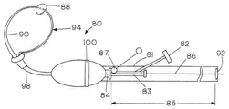
図3は、全体が80のバルーン・カテーテル・アブレーション・システムの一実施形態の概略図を示しており、これは平坦な制御ハンドル部材81を含んでおり、この部材は、流体物質をバルーン88に加えるためのRF/低温液体コネクタ82を含む。アブレーション(RF/低温液体)バルーン・カテーテルは、近位端カテーテル・シャフト滑り又は操作ハンドル83を有しており、これはガイドシース84内に延在するように示されている。近位端ハンドル83は、90で示されるバルーン・アブレーション・カテーテルの近位端である。カテーテルは、ガイドワイヤ86上に摺動可能に設置されており、その両方が、ガイドシース84を介して心房又はその他の空洞に送達される。アブレーション・バルーン・カテーテル・シャフトが、ガイドワイヤの相対的に剛性の部分にわたって偏向可能なシースに挿入される。ガイドワイヤの相対的に柔軟な部分は、シースから延びており、所定の場所にロックされることで、バルーン・カテーテルがガイドワイヤに沿って移動する際、ガイドワイヤがシース内で浮遊したり移動したりするのを阻止することができる。これを達成するために、87で表される可動式のロック・デバイスが設けられる。ガイドワイヤ・ループに沿ったバルーンの位置は、カテーテル近位端ハンドル83をガイドワイヤの一部86に沿ってその上を移動させることによって変えることができる。ガイドワイヤ固定ロックは92で示されている。これにより可変長のガイドワイヤ固定地点が可能になることで、突き出たループのサイズを変え、アブレーション・バルーンがさらなる距離を覆うことが可能になる。ハンドル83によって制御されたときの調節可能なガイドワイヤ・ループ94上のアブレーション・バルーン・カテーテルの摺動範囲が、矢印85によって示されている。偏向可能なシースの一部が98で示されており、柔軟な可撓性のガイドワイヤ・ループの一部が94で示されている。シース偏向リングが100で示されている。
FIG. 3 shows a schematic representation of an embodiment of an overall 80 balloon catheter ablation system, which includes a flat
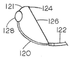
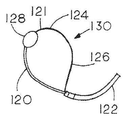
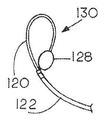
図4A〜図4Eの5つのパネルは、偏向可能なシース122の内部からガイドワイヤ121上を進められたアブレーション・カテーテル・シャフト120を示している。124のガイドワイヤの遠位端は、引っ張り線又は引っ張りワイヤ126に装着されており、このワイヤは制御ハンドル(図示せず)から制御されている。ガイドワイヤ上を進められたバルーン・アブレーション・デバイスが128で示されている。アブレーション・デバイスは、図4Aにおいてしぼんだ状態で示されている。この状態において、偏向可能なガイドシースは既に、左心房又はその他の空洞内に貫入している。図4Bでは、バルーンは膨張し、引っ張りワイヤ126は、ガイドワイヤ124の端部をシースに向かって引き寄せることで、ガイドワイヤ・ループを形成するように示されている。図4Cでは、ガイドワイヤの端部がシースの中に戻るように引っ張られ、ループ130を形成している。図4D及び図4Eは、シース内でガイドワイヤを進めたり後退させたりすることによって、ループ130のサイズをどのように調節することができるかを示している。ガイドワイヤ上のバルーン128の位置もまた、アブレーション・バルーン・シャフト83(図3)をガイドワイヤ上で進めたり後退させたりすることによって、図4Dから図4Eに示されるように調節することができる。
The five panels of FIGS. 4A-4E show the
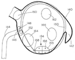
図5は、調節可能なループ・ガイドワイヤによって左心房内に誘導されたアブレーション・バルーンが、いかにして円周方向の損傷を形成することができるかを示す概略図である。このような左心房の壁が140によって表されており、左心房の付属器官は142で示されている。経中隔ガイドシース144は、146の右心房と左心房の間の隔壁を貫通するように示されている。シースには、一体式の膨張可能なバルーン148が含まれており、これは、手術中の経中隔の破損時の断裂から隔壁を保護する塩水によって満たされている。バルーン・カテーテル・シャフトが150で示されており、可撓性の部分を有するガイドワイヤが152で示されている。セグメント化されたアブレーション・バルーンは、高周波又は極低温アブレーション・デバイスのいずれかであってよく、154で示されており、サーミスタと記録電極は、各々のバルーン表面部分155において156として示されている。さらにリング電極がバルーンの各々の端部に設けられ、その一方が158で示されている。この図はさらに、肺静脈の出口の場所を示しており、これには右上肺静脈(RSPV)160、左上肺静脈(LSPV)162、右下肺静脈(RIPV)164及び左下肺静脈(LIPV)166が含まれる。
FIG. 5 is a schematic diagram showing how an ablation balloon guided into the left atrium by an adjustable loop guide wire can form a circumferential injury. The wall of such a left atrium is represented by 140, and the appendages of the left atrium are represented by 142. The
図5に関連して注目されるように、セグメント化されたアブレーション・バルーン154は、ガイドワイヤ・ループによって左心房140の壁に対してきっちりと保持される。必要に応じてより多くのガイドワイヤを挿入し、ガイドワイヤ・ループに沿って一定量ずつアブレーション・バルーン154の位置を調節することによって、ガイドワイヤ・ループのサイズを調節することにより、完全に連続する円周方向の損傷を左心房に形成することが可能であることが分かる。
As noted in connection with FIG. 5, the
図6は、図5と同様の図であり、セグメント化された塗装アブレーション・バルーン154を固定するための代替のシステムを示しており、そこではループシステムの代わりに、比較的剛性のガイドワイヤ170の固定用の柔軟な部分が、左心房の付属器官142の中に埋め込まれるように設けられ、アブレーション・バルーンがその後ガイドワイヤ170上をたどり、左心房の周りに線形の損傷を形成することができる。僧帽弁が、174で示されている。
FIG. 6 is similar to FIG. 5 and shows an alternative system for fixing the segmented
図7は、図6と同様の概略図であり、LSPV162の開口部をちょうど超えた開口部又は洞腔領域に位置するセグメント化された塗装アブレーション・バルーン154を示しており、この場合それを利用して肺静脈を隔離する損傷を形成することができる。このやり方において、各々の肺静脈を処置することで、肺静脈隔離損傷を形成することができる。
FIG. 7 is a schematic similar to FIG. 6 showing a segmented
図8は、LSPV196の開口部に挿入されて示される高周波又は極低温バルーン180を示す概略図である。バルーンは、経中隔シース182及びJタイプの4Fループ記録カテーテル184によってPV内に誘導される。Jループは、記録及び刺激電極186のアレイを含んでおり、バルーンはさらに遠位リング電極188と、近位リング電極190とを備えることで、アブレーション(具体的には極低温バルーンを使用する場合)処置におけるインピーダンスの測定を行なうことで、肺静脈の閉鎖、及びその後の損傷の特性を規定する。心房壁が192で示されており、肺静脈は、194、196、198及び200によって示されている。図8の実施形態を利用する場合、バルーン・カテーテル180は、図6及び図7のものと同様のやり方で構築することができる。カテーテルが、極低温デバイスの場合、アブレーション措置中に氷のボールが形成され、極低温アブレーション中に形成された氷のボールの両端の記録作業及びインピーダンス測定によって、氷のボールのサイズの損傷の完成、及びアブレーションの効果を検証することができる。 FIG. 8 is a schematic diagram showing a high frequency or cryogenic balloon 180 inserted and shown in the opening of LSPV196. The balloon is guided into the PV by a transseptal sheath 182 and a J-type 4F loop recording catheter 184. The J-loop contains an array of recording and stimulating electrodes 186, and the balloon further comprises an distal ring electrode 188 and a proximal ring electrode 190 for ablation (specifically, when using a cryogenic balloon). ) By measuring the impedance in the procedure, the characteristics of pulmonary vein closure and subsequent injury are defined. The atrial wall is indicated by 192 and the pulmonary veins are indicated by 194, 196, 198 and 200. When utilizing the embodiment of FIG. 8, the balloon catheter 180 can be constructed in the same manner as that of FIGS. 6 and 7. If the catheter is a cryogenic device, ice balls are formed during the ablation procedure, and recording work and impedance measurements at both ends of the ice balls formed during the cryogenic ablation complete the damage to the size of the ice balls. , And the effect of ablation can be verified.
バルーン・アブレーション・デバイスと組み合わせたJタイプのループPV記録、刺激及びインピーダンス測定カテーテルは、極低温バルーン技術を用いたPV隔離を実現することができることが、成功するかどうかは、バルーンとPV組織がしっかりと接触し、PVが完全に閉鎖されることで、アブレーション処置においてバルーンを囲む心房に血流が全く流れないことに決定的に左右されることが理解されよう。これは、例えばバルーン・ガイドワイヤ内の中央内腔を介してPV内に染料を注入することによって検証することができる。染料が静脈内に集まって見える場合、この静脈は適切に塞がれていると推測することができる。静脈が完全に閉鎖されず、結果として生じる損傷が完全な円周方向の損傷ではない場合、すなわち隙間が生じている、或は組織が単に非活動状態になることで一時的に隔離された場合、これにより処置が失敗に終わり、さらなる介入が必要となる。 J-type loop PV recording, stimulation and impedance measurement catheters combined with a balloon ablation device can achieve PV isolation using cryogenic balloon technology, whether the balloon and PV tissue will succeed. It will be appreciated that close contact and complete closure of the PV will be decisively dependent on no blood flow to the atrium surrounding the balloon during the ablation procedure. This can be verified, for example, by injecting the dye into the PV through the central lumen within the balloon guide wire. If the dye appears to collect in a vein, it can be inferred that the vein is properly blocked. If the vein is not completely closed and the resulting damage is not a complete circumferential damage, i.e. there is a gap, or the tissue is temporarily isolated simply by inactivity. This leads to unsuccessful treatment and requires further intervention.
Jループ記録/刺激カテーテルは、いくつかの目的を果たすことが理解されよう。(1)それは、バルーン・アブレーション・カテーテルのガイドとして機能することで、バルーンを所望のPV開口部に対して長手方向の中央の位置に配置する、(2)それは、カテーテルを静脈の中に固定させ、ループを、開口部をちょうど越えた静脈洞腔内に位置決めする、(3)RF又は極低温アブレーションにおいてループ電極186によって横隔神経にペーシングを適用することができ、その一方で横隔膜の運動を監視することで、横隔神経が切除されないことを保証する、(4)それによって、極低温アブレーションにおけるインピーダンスを監視することにより損傷の成熟を検証することができる、及び(5)それによって、RF及び極低温アブレーションにおける静脈から心房又は心房から静脈への伝導を測定することができる。 It will be appreciated that the J-loop recording / stimulation catheter serves several purposes. (1) It places the balloon in a longitudinally central position with respect to the desired PV opening by acting as a guide for the balloon ablation catheter, (2) it anchors the catheter into a vein. And the loop is positioned in the venous sinus just beyond the opening, (3) pacing can be applied to the phrenic nerve by the loop electrode 186 in RF or cryogenic ablation, while the movement of the diaphragm. By monitoring the diaphragm, it is possible to ensure that the phrenic nerve is not excised, (4) thereby verifying the maturity of the injury by monitoring the impedance in cryogenic ablation, and (5) thereby. Vein-to-vein or atrium-to-venous conduction in RF and cryogenic ablation can be measured.
低強度のRFエネルギーを、バルーンのちょうど近位にあるバルーン・カテーテル・シャフト上に位置決めされた基準電極190と共に(図8に示される)遠位バルーン・リング電極188に印加することで、バルーンの両端の伝導率を測定することができる。バルーンが完全にPVを閉鎖した場合、インピーダンスが上昇し、この測定値を利用してPVの閉鎖を検証することもできる。さらにシステムが極低温バルーンを含む場合、PV閉鎖の評定及び極低温の氷のボールのサイズの評定もまた、近位バルーン・リング電極190と、遠位バルーン・リング電極188間のインピーダンスの変化を測定することによって実現することができる。氷は極めて伝導性が低いため、氷のボールがPVを完全に包み込む際、そのインピーダンスは、劇的に上昇することが認められ、これによりPVの閉鎖及び極低温の損傷の成熟の信頼できる指標がもたらされる。 By applying low intensity RF energy to the distal balloon ring electrode 188 (shown in FIG. 8) with a reference electrode 190 positioned on the balloon catheter shaft just proximal to the balloon, the balloon The conductivity at both ends can be measured. If the balloon completely closes the PV, the impedance rises and this measurement can also be used to verify the PV closure. In addition, if the system includes a cryogenic balloon, the PV closure rating and the cryogenic ice ball size rating will also change the impedance between the proximal balloon ring electrode 190 and the distal balloon ring electrode 188. It can be realized by measuring. Due to the extremely low conductivity of ice, its impedance is found to increase dramatically when the ice ball completely encloses the PV, which is a reliable indicator of PV closure and maturation of cryogenic damage. Is brought about.
図8に示される実施形態では、複数の離間したリング電極186とサーミスタ(図示せず)を備えたJループが、まず196でのように静脈内に配置される。J形状によりカテーテルを静脈内に固定し、ループは、示されるように開口部をちょうど超えた静脈洞腔内に位置決めされる。バルーン・アブレーション・カテーテルは、それをJカテーテル・シャフト上で進めることによって所定の位置に誘導される。低電力で高周波数の電流(これは、1ワット、550KHz未満を利用することができる)をJループ上の1つ又は複数の電極186に、或いは遠位リング電極(188)及びバルーンのちょうど近位に位置決めされたリング電極190に送達することによって、ベースライン・インピーダンスを測定することができる。このインピーダンスはまた、電極188及び190を利用してバルーンのインピーダンスを測定することによって計ることができる。上記で指摘したように、バルーンが膨張した後、静脈がしっかりと閉鎖された場合、第2のインピーダンス測定はインピーダンスの上昇を示すはずであり、一部分のみが閉鎖されている場合は、インピーダンスの変化は検知されない。さらなるインピーダンスの上昇もまた、遠位電極を包み込む氷のボールの形成を示唆する極低温バルーン・アブレーションによって記録される。 In the embodiment shown in FIG. 8, a J-loop with a plurality of isolated ring electrodes 186 and a thermistor (not shown) is first placed intravenously as in 196. The J-shape secures the catheter intravenously and the loop is positioned within the venous sinus just beyond the opening as shown. The balloon ablation catheter is guided into place by advancing it on the J-catheter shaft. Low power and high frequency current (which can utilize less than 1 watt, 550 KHz) to one or more electrodes 186 on the J-loop, or just close to the distal ring electrode (188) and balloon. The baseline impedance can be measured by delivering to the ring electrode 190 positioned in the position. This impedance can also be measured by measuring the impedance of the balloon using electrodes 188 and 190. As pointed out above, if the vein is tightly closed after the balloon is inflated, the second impedance measurement should show an increase in impedance, and if only part is closed, the change in impedance. Is not detected. Further increases in impedance are also recorded by cryogenic balloon ablation, which suggests the formation of ice balls surrounding the distal electrode.
Jカテーテルは、好ましくは、事前成形された3〜4Fカテーテルであり、これはアブレーション・バルーンの中央チャネルに挿入される。カテーテルのJの部分がPVに挿入され、カテーテルの円形部分は、PVの洞腔を取り囲むリング記録/刺激電極及びサーミスタを備えている。バルーン・カテーテルは、Jカテーテルをガイドワイヤとして利用してJカテーテルの上を進められる。バルーンは、PVを閉鎖するように位置決めされ、カテーテルの円形部分は、PVに接触するバルーンのちょうど遠位でバルーンを取り囲む。バルーン・シャフト又はJカテーテルのループ部分のいずれかに配置された事前に選択されたリング電極に低電力のRFエネルギーが印加され、バルーンの膨張の前後、及び特に極低温バルーン実施形態の場合のアブレーションにおけるインピーダンスを測定する。 The J-catheter is preferably a preformed 3-4F catheter, which is inserted into the central channel of the ablation balloon. The J portion of the catheter is inserted into the PV, and the circular portion of the catheter comprises a ring recording / stimulation electrode and a thermistor surrounding the PV cavity. The balloon catheter can be advanced over the J-catheter using the J-catheter as a guide wire. The balloon is positioned to close the PV, and the circular portion of the catheter surrounds the balloon just distal to the balloon in contact with the PV. Low power RF energy is applied to a preselected ring electrode located on either the balloon shaft or the loop portion of the J-catheter to ablate before and after balloon expansion, and especially in the case of cryogenic balloon embodiments. Measure the impedance in.
手術中、RF及び極低温バルーン実施形態に関する送達及び組織接触方法は同じであり得ることを理解されたい。高度に導電性の要素と、サーミスタは、RF及び外側の極低温バルーンの両方の外面を囲むように円周方向に分散される。 It should be understood that during surgery, delivery and tissue contact methods for RF and cryogenic balloon embodiments may be the same. The highly conductive element and the thermistor are circumferentially dispersed so as to surround the outer surfaces of both the RF and the outer cryogenic balloon.
図9は、本発明の代替の一実施形態の概略図を含んでおり、これは線形の損傷を形成することを目的とした多アブレーション電極式のカテーテル・システムの形態であり、特に肺静脈間に位置する組織内に線形の損傷を形成するように設計されることで、このような組織の隔離を実現し、心房細動アブレーションを成功させるのに最も重要であると考えられる特定の態様である。図9に示されるように、離間したワイヤが巻き付いたアブレーション電極302のアレイを包含する可撓性の多電極アブレーション・カテーテル300は、2つの部材304及び306を有する支持シース構成から延びており、これらの部材は、支持体及びトルク可能なアブレーション・カテーテル支持シースを構成している。カテーテル支持シース部材304及び306は、メインの経中隔ガイドシース308から延びている。支持シースの延長部は、310及び312で示されており、支持シースを偏向可能な経中隔ガイドシースにロックするためのロック・デバイスは、314で示されている。偏向制御ハンドルが316で示され、アブレーション・カテーテル・コネクタが318で示されており、これは接続ライン320を経由して電極302に電力を供給している。他のサイズを利用することも可能であるが、可撓性の多電極アブレーション・カテーテル300は通常は4Fであり、ワイヤが巻き付いた電極302は5mmの長さであり、2mmの隙間をその間に有することができる。支持及びトルク可能なカテーテル・ガイドシース304及び306がそれぞれ事前に成形されることで、それらを肺静脈に入るように操作することが可能になる。
FIG. 9 contains a schematic representation of an alternative embodiment of the invention, which is a form of a multi-ablation electrode catheter system aimed at forming a linear injury, especially between the pulmonary veins. Designed to form linear injuries within the tissue located in, in certain embodiments that are considered most important for achieving isolation of such tissue and successful atrial fibrillation ablation. be. As shown in FIG. 9, the flexible
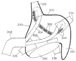
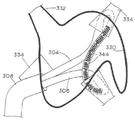
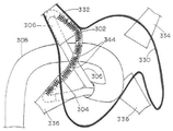
1対の肺静脈におけるガイドシース304及び306の配置が、図10〜図13の概略図によって示されており、ここでは左心房壁は、330によって表されており、肺静脈は、RSPV332、LSPV334、RIPV336及びLIPV338を含む。左心房の付属器官は340で示されており、僧帽弁は342で示されている(図10)。
The placement of the
このやり方において、図10は、線形の損傷が、どのように右上肺静脈332と左上肺静脈334の間に形成されるかを示している。安定化及び支持ガイドシース304及び306によって開口部及び肺静脈の洞腔が貫通され、カテーテル電極のアレイのための支持体も形成する。344としてのサーミスタは、アブレーション/記録電極302間に配置することができる。同じやり方で、図11は、LSPV334とLIPV338との間のアブレーションを示している。図12は、LIPV338とRIPV336との間のアブレーションを示している。最後に図13は、RSPV332とRIPV336との間のアブレーションを示している。
In this manner, FIG. 10 shows how a linear injury is formed between the right right
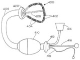
このように可撓性の多電極アブレーション・カテーテル300は、1対のより剛性のガイドシース304及び306の中に配置され、これらのシースは、偏向可能なガイドシース308の中に配置され、このガイドシースは、経中隔デバイスである。手術中、ひとたびメインのシースが所望の空洞に入るように進められると、アブレーション・カテーテル300並びに2つの支持ガイドシース304及び306は、メインのシースから出て空洞に入るように進められる。支持ガイドシース304及び306がそれぞれ事前に成形されることで、それらを肺静脈に入るように操作することが可能になる。支持シース304及び306は、その近位部分を押す且つ/又は回転させてメインの偏向可能シース308に出入りさせることによって個別に進めることができる。支持シースの位置は、偏向制御ハンドル316にあるロック機構314を緩めたり締めたりすることによって、所定の場所にロックさせることができる。図面に示されるように、アブレーション・カテーテルを組織の両端にピンと張るように維持しながら、支持シースが所望の肺静脈に入るように押し込まれると、アブレーション・カテーテルと所望の組織との良好な接触が確実になる。別の実施形態が図14及び図15に概略的に見られる。この実施形態は本質的に、図9〜図13に示される実施形態を簡素化したタイプであり、ここではワイヤが巻き付いたアブレーションと、測定電極402と、介在するサーミスタ404とを備えた多電極カテーテル400が、メインの偏向可能なガイドシース406に直接挿入されることで、シースの端部にループを形成している。408で示される延長ロッドを利用して、ループの形状を修正する。ロック・デバイス412を有するハンドル及び偏向制御装置が410で示されており、多電極とサーミスタのコネクタは414で示されている。延長ロッド制御装置が416で示されており、止め具付きの引き紐が418で示されている。隔壁保護バルーンが420で示されている。図15では、左心房壁が422で示されており、左心房の付属器官は424で示されている。肺静脈の開口部は、426、428、430及び432で示されており、僧帽弁は434で示されている。展開させる前は、アブレーション・カテーテル400をメインの偏向ガイドシースの開口部の中に引っ込めることが可能であることにより、418の引き紐又は引っ張りワイヤを利用して、メインのガイドシース406のサイズを最小限にすることができる。絶縁された可撓性の延長ロッド408によってカテーテル・ループのさらなる支持と安定性を実現し、組織との接触を改善させる。カテーテルの移動度及び位置は、メインシースを回転式に偏向させることにより所望通りに達成させることができ、すなわちアブレーションカテーテル・トルクの拡大及びカテーテル・ループの拡張、絶縁ロッド408の伸張又は収縮が実現する。
Thus the flexible
図16は、本発明によるRFアブレーション・システムのための監視及び制御システムの概略図である。システムには、カテーテル・システム500が含まれ、これはガイドワイヤ506に重なるカテーテル・シャフト504上に設置されたバルーン・カテーテル502を有する。シースは508で示されている。バルーン・カテーテルは、複数のサーミスタと、記録電極510と、RFアブレーション電極512とを含んでいる。カテーテルはさらに、ブロック514によって表される機械的に操作する制御装置並びに液体の膨張及び循環制御装置を含んでいる。
FIG. 16 is a schematic diagram of a monitoring and control system for an RF ablation system according to the present invention. The system includes a
入力及び出力データ処理及びエレクトログラムRFフィルタを含むRFエネルギー電力生成システムが520で示されており、RF制御システム522に関連付けられている。RF発生器は、ブロック524で示される視覚的な出力、すなわちスクリーン・ディスプレイ・デバイスに接続されており、526の記録システムも接続されている。
An RF energy power generation system including input and output data processing and an electrogram RF filter is shown in 520 and is associated with an
RF電力発生器は、各々の電極が別々に接続され、別個に制御可能であるため、いずれの多電極RFカテーテル・システムにおける各々のアブレーション電極に対してもRF電力を制御し調整するようにプログラムされている。電力の送達が制御されることで、標的とする組織としっかりと接触する電極のみが通電され、所望の電力を慎重に調節することで血液やアブレーションされる組織を過剰に加熱するのを避ける。アブレーションされる組織を過剰に加熱することにより、炭化物の形成が生じ、これが発作につながる恐れもある。したがって各々独立した電源は、検知した温度、及び温度上昇の割合を表す温度変化の一次導関数(dT/dt)に基づいて調節される。リアルタイムの局所的な電気的な活動が厳密に監視される。これには、エレクトログラム振幅の記録、局所的なエレクトログラムの最大周波数の変化及びインピーダンスの変化が含まれる。 The RF power generator is programmed to control and adjust the RF power for each ablation electrode in any multi-electrode RF catheter system, as each electrode is connected separately and can be controlled separately. Has been done. By controlling the delivery of power, only the electrodes that are in close contact with the targeted tissue are energized, and careful adjustment of the desired power avoids overheating blood and ablated tissue. Excessive heating of the ablated tissue results in the formation of carbides, which can lead to seizures. Therefore, each independent power source is adjusted based on the first derivative (dT / dt) of the temperature change, which represents the detected temperature and the rate of temperature rise. Real-time local electrical activity is closely monitored. This includes recording electrogram amplitudes, local changes in the maximum frequency of the electrogram, and changes in impedance.
ひとたびRF電力のスイッチが入れられると、電力発生器システムは、事前にプログラムされた手順に従ってRF電力を調整するが、この手順は以下の通りであってよい。
1. 接触後に組織の生存能力が、容認可能なパラメータ、例えば
a. 局所的なエレクトログラム>1mV
b. 最大エレクトログラム周波数>8Hz
c.インピーダンス<180オームに従って規定される。
低電力の設定で開始し、電力が増大することで、事前設定されたレベル、例えば5℃/秒=dT/dtにおける電極の温度変化の割合を制御する。
2. 最大限の事前設定温度、例えば65℃に到達する。
3. インピーダンスが事前設定されたレベル(例えば150〜180オーム)を超えて上昇した場合、或は局所的なエレクトログラムがベースライン・レベルから50%又はそれ以上低下した場合(及び/又はエレクトログラム振幅と連動して)、或いは局所的なエレクトログラム周波数が、例えばベースライン値から30%低下した場合、電力の入力を終了する。
4. 手術中、望ましい場合、項目3における特定の値を無効にすることができる。
5. エレクトログラム・データ及びインピーダンスによってアブレーションが成功したことが示される場合、電力を最小限まで低下させる。
Once the RF power is switched on, the power generator system adjusts the RF power according to a pre-programmed procedure, which may be as follows:
1. 1. The viability of the tissue after contact is an acceptable parameter, eg a. Local electrogram> 1 mV
b. Maximum electrogram frequency> 8Hz
c. Impedance <180 ohms.
Starting with a low power setting and increasing power, the rate of temperature change of the electrodes at a preset level, eg 5 ° C./sec=dT/dt, is controlled.
2. 2. The maximum preset temperature is reached, eg 65 ° C.
3. 3. If the impedance rises above a preset level (eg 150-180 ohms), or if the local electrogram drops by 50% or more from the baseline level (and / or with the electrogram amplitude). (In conjunction), or if the local amplitude frequency drops, for example, by 30% from the baseline value, the power input is terminated.
4. During surgery, certain values in item 3 can be overridden if desired.
5. If the electrogram data and impedance indicate successful ablation, reduce power to a minimum.
RF電力発生器システムは、アブレーション電極及びサーミスタからの必要なパラメータの全てに関連するデータを受信するように設計されており、これには局所的なエレクトログラム振幅及びパーセントの変化、最大エレクロトグラム周波数温度、温度の変化の割合(dT/dt)のインピーダンス、出力電力及び印加時間が含まれる。 The RF power generator system is designed to receive data related to all of the required parameters from the ablation electrode and thermistor, including local electrogram amplitude and percentage changes, maximum electronics. Includes frequency temperature, impedance of rate of change in temperature (dT / dt), output power and application time.
受信したデータが、局所的な組織がうまくアブレーションされ、電力が終了したことを示すと、次の局所的な組織をアブレーションするためにカテーテルを再度位置決めすることができる。 Once the received data indicates that the local tissue has been successfully ablated and the power has been depleted, the catheter can be repositioned to ablate the next local tissue.
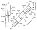
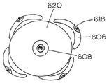
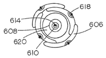
RFバルーン・アブレーション・カテーテル・デバイスの別の実施形態が、図17において全体を600で示されており、バルーンは、完全につぶされた状態である。デバイスは、外側管状部材と、部分602及び603を有するように示されるガイド・カテーテル又はガイドシースとを含む。ガイド・カテーテル又はシースは、拡張可能な、すなわちバルーン部分604をその間に含んでいる。拡張可能部分604には、導電電極アブレーション要素606が備わっており、これはシャフト部分602及び603に接続されている。電極要素は、好ましくは、導電性のリボン状の形態であり、これは内側の拡張可能なバルーン・デバイス607の外側に設置され、それとは独立している。図20A及び図20Bに最もよく見られるように、電極要素は、デバイス604の拡張する部分が、図20Bに示されるようにつぶされた又は格納された位置にあるときは重なり合い、図20Aに示されるようにバルーン・デバイス607が拡張したとき、わずかに隔てられる。このやり方では、拡張する、すなわちバルーン・デバイスを使用して、展開後のアブレーション・デバイス要素が描く直径を調節することができる。これらの図面は4つの電極要素を描いているが、任意の好適な数を利用することができる。要素は全て別々に接続され、アブレーション、温度及び電気的活動を監視するためのデバイスを含んでいる。
Another embodiment of the RF balloon ablation catheter device is shown entirely at 600 in FIG. 17, in which the balloon is in a completely crushed state. The device includes an outer tubular member and a guide catheter or guide sheath indicated to have
外側カテーテル・シャフトは、付加的な内側の同心の中空の管を中に含んでおり、この管は、中間の管状部材608と、最も内側の管状部材610とを含む。最も内側の管状部材610は、カテーテルの先端612に接続し、軸方向に調節可能なガイドワイヤ614を中に含んでいる。これらは図17では露出した状態で示されている。管状部材610はまた、特定の手順で射出されるように設計された流体が、カテーテル・ハンドルから導かれ、カテーテルを介して送達されることを可能にする経路を形成する。わずかに大きな中間の管状部材608が、部分604において607にある拡張バルーン・デバイスの内部と接続し、膨張流体のための経路を形成する。外側の管、すなわちカテーテル・シャフト部材は、616のようなワイヤを中に含んでおり、このワイヤが、アブレーション要素に接続し、サーミスタ要素及び記録電極にも接続しており、これらの電極は618でのようにアブレーション要素606の中に埋め込まれている。
The outer catheter shaft contains an additional inner concentric hollow tube, which contains an intermediate
図18A及び図18Bは、中空のアブレーション・デバイス600の比較形態を示しており、拡張する、すなわちバルーン・デバイスのつぶれた状態と、拡張した状態それぞれを示している。図20Bに最もよく示されるように、リボン電極要素606は、バルーン部分604が、しぼんだ、又は格納位置にあるときは重なり合い、逆に拡張した状態では、図18B及び図20Aに示される電極は、バルーンの拡張によってわずかに隔てられ、バルーン材料607のわずかな部分が露出する。これにより最大限のアブレーション電極面を露出させることができ、さらにアブレーション要素を個別に操作することも可能になる。このような構成により、バルーン・デバイスを1つ配置するだけで、例えば肺静脈内での周辺部のアブレーションが可能になる。リボンアブレーション要素は、手術後、バルーン・デバイスがつぶされる、又はしぼんだ際、アブレーション要素が再び重なり合う構成を取り、鋭利な縁部が見えたり、露出したりすることで隣接する組織に悪影響を与える恐れがないように構成されるべきである。リボン電極606の端部は、部分602と603の間に固定されるため、システムの要素が、ガイドワイヤ614上に独立して載ったとき、これらの要素間の距離は、バルーン材料607が膨張したとき短くなる。より剛性の構造が所望される場合、バルーンが膨張する際にシャフトが偏向するように特定の実施形態を作成することができる。
18A and 18B show a comparative form of the
図18B及び図19に特に示されるように、バルーン・アブレーション・カテーテル・デバイスはさらに、隔壁保護バルーン630を含んでおり、追加のガイドシースの一部が632で示されている。先に記載した実施形態でのように、このデバイスは、隔壁組織を貫通するように設計されており、手術中にバルーン630が膨張することにより、ガイドシース632が隔壁組織から押し戻され、場合によって隔壁に損傷を与えるのを防ぐ。概して、左心房におけるアブレーションが関与する場合、ガイドシースを利用して、隔壁を右心房から左心房に貫通する。図18B及び図19に示されるように、先に記載した実施形態でのように、ガイドワイヤ614によって左心房などの空洞内に形成されたガイドワイヤ・ループによって、連続するステップでアブレーション・バルーンのための安定した軌道が配置されるように形成されることで、所望通りに空洞の周辺部の周りに線形の損傷を形成する。このようなバルーン・デバイスは、手術中ガイドワイヤ上を所望通りに進めることができる。図3に示されるハンドル制御装置を含めた先の実施形態で示されるものなどの制御装置は、いずれの実施形態にも利用することができる。
As specifically shown in FIGS. 18B and 19, the balloon ablation catheter device further includes a
代替の構成が、図21A、21B及び22A、22Bに描かれている。図21A及び図21Bでは、RFバルーン・アブレーション・カテーテル700は、図17のものと同様の構造で示されており、これは、離間したカテーテル・シャフト要素702及び703を有するカテーテル・シャフトを含んでおり、これらの要素は、拡張部分704の外側でリボンアブレーション要素706に接続されることによってその間にまたがっている。このような要素はまた、埋込み式のサーミスタと、記録電極を718として備えている。残りの構造及び構造体は、図17のものと同様であり、同心の管状部材708及び710を含んでおり、これらによって、図17の実施形態における要素608と610と同じ機能を実現している。この実施形態では、リボン電極要素706は、膨張バルーン・アブレーション部分704の外周を囲むらせん状のパターンで配置されている。十字形のパターンが図21Bに704Bで示されている。
Alternative configurations are depicted in FIGS. 21A, 21B and 22A, 22B. In FIGS. 21A and 21B, the RF
さらに別の同様の実施形態が、図22A及び図22Bに描かれており、ここではRFバルーン・アブレーション・カテーテル・デバイス800が示されており、このデバイスもやはり、格子又は十字形のパターンで配置された特定のパターンのリボン電極806を含んでおり、そこでは別個のアブレーション要素又は電極は互いから絶縁されている。カテーテルはまた、部分802、803及び804を含んでいる。ガイドワイヤ管が808で示されており、ガイドワイヤは814で示されている。このアブレーション要素もまた、埋込み式のサーミスタ及び電気的活動を記録する要素を818で備えている。このパターンもまた、肺静脈の開口内でのように完全な円周方向のアブレーションを保証する。デバイスは図面において、つぶれた又はしぼんだ状態と、広がった又は膨張した状態の両方で示されている。
Yet another similar embodiment is depicted in FIGS. 22A and 22B, where the RF balloon
多くのサイズが可能であるが、リボン状のアブレーション要素は典型的には、およそ30mmの長さで3mmの幅であり、楕円形の形状であってよい。バルーン・アブレーション・カテーテルは、完全に拡張したときおよそ20mmの直径であり、しぼんだ又は収容された状態ではおよそ11F(3.6mm)であるべきである。ガイド又は展開シースは、およそ12F(3.9mm)である。バルーン及び電極は、同様に生体適合性である任意の好適な材料であってよく、このような材料はよく知られている。 Although many sizes are possible, the ribbon-shaped ablation element is typically about 30 mm long and 3 mm wide and may be oval in shape. The balloon ablation catheter should be approximately 20 mm in diameter when fully expanded and approximately 11F (3.6 mm) when deflated or contained. The guide or unfolding sheath is approximately 12F (3.9 mm). Balloons and electrodes may be any suitable material that is also biocompatible and such materials are well known.
上記の記載及び図面から、これらの実施形態の機能性に帰する本発明に関連する独自の性質は、特にヒトの心臓における心房細動の制御に関して精密で優れたアブレーションを実現することを目的として存在することは明らかであろう。しかしながらこのデバイス及び技術は、心臓のいかなる領域にも適用することができることを理解されたい。したがって、これは、右心室及び左心室に適用され、並びに心室性頻拍のマッピング及びアブレーションにも適用することができる。心房細動に関して、本発明によるカテーテル・システムは、その接触とカテーテルの扱い易さを大いに改善することでより予測可能な損傷を形成し、アブレーションされる組織の量を最小限にすることが分かっている。 From the above description and drawings, the unique properties relating to the invention attributed to the functionality of these embodiments are aimed at achieving precise and superior ablation, especially with respect to the control of atrial fibrillation in the human heart. It will be clear that it exists. However, it should be understood that this device and technique can be applied to any area of the heart. Therefore, this applies to the right and left ventricles, as well as the mapping and ablation of ventricular tachycardia. With respect to atrial fibrillation, the catheter system according to the invention has been found to form more predictable damage and minimize the amount of tissue ablated by significantly improving its contact and catheter manageability. ing.
特許法令に準拠し、新たな原理を適用し、必要なときにこのような特化された構成要素を構築し利用するのに必要な情報を当業者に与えることを目的として、本発明を本明細書においてかなり詳細に記載してきた。しかしながら本発明は、殊更異なる装備及びデバイスによっても実行することができ、本発明自体の範囲から逸脱せずに装備と作動手順の両方についての種々の修正形態を達成することができることを理解されたい。 The present invention is intended to provide those skilled in the art with the information necessary to comply with patent laws, apply new principles, and build and utilize such specialized components when needed. It has been described in considerable detail in the specification. However, it should be understood that the present invention can also be carried out with particularly different equipment and devices, and various modifications can be achieved for both equipment and operating procedures without departing from the scope of the invention itself. ..
Claims (6)
(b)前記ガイド本体シースの前記遠位端部から伸張可能であり、静脈内に配置されて誘導及び記録カテーテル・デバイスを静脈内に固定するJ形状部と、前記J形状部から近位側に延在し記録要素のアレイを備えた円形のループ部と、を備えて構成されたJループの遠位端を有する誘導及び記録カテーテル・デバイスと、
(c)前記誘導及び記録カテーテル・デバイス上を進むように設計され、誘導及び記録カテーテル・デバイスをガイドとして前記誘導及び記録カテーテル・デバイス上を進むように誘導され、前記誘導及び記録カテーテル・デバイスによって安定される膨張可能な極低温アブレーション・バルーン・デバイスと、
(d)前記ガイド本体シースからの前記誘導及び記録カテーテル・デバイスの伸張を調節するための制御要素と、
(e)前記膨張可能な極低温アブレーション・バルーン・デバイスの遠位において前記アブレーション・バルーン・デバイスに隣接して配置された遠位リング電極、および、前記アブレーション・バルーン・デバイスの近位において前記アブレーション・バルーン・デバイスに隣接して配置された近位リング電極と
を備える、組織をアブレーションするためのデバイス。 (A) A guide body sheath having a deflectable distal end with an opening in it,
(B) A J-shaped portion that is extendable from the distal end of the guide body sheath and is placed intravenously to secure the guiding and recording catheter device in the vein, and a proximal side from the J-shaped portion. A guidance and recording catheter device with a distal end of a J-loop configured with a circular loop portion extending to and equipped with an array of recording elements.
(C) Designed to travel on the guidance and recording catheter device, guided to travel on the guidance and recording catheter device with the guidance and recording catheter device as a guide, by the guidance and recording catheter device. A stable, inflatable ultra-low temperature ablation balloon device,
(D) A control element for regulating the extension of the guidance and recording catheter device from the guide body sheath.
(E) A distal ring electrode located adjacent to the ablation balloon device distal to the inflatable cryogenic ablation balloon device, and the ablation proximal to the ablation balloon device. -A device for ablating tissue, with a proximal ring electrode placed adjacent to the balloon device.
Applications Claiming Priority (5)
| Application Number | Priority Date | Filing Date | Title |
|---|---|---|---|
| US12/961,781 | 2010-12-07 | ||
| US12/961,781 US11246653B2 (en) | 2010-12-07 | 2010-12-07 | Catheter systems for cardiac arrhythmia ablation |
| US13/106,309 US8998893B2 (en) | 2010-12-07 | 2011-05-12 | Catheter systems for cardiac arrhythmia ablation |
| US13/106,309 | 2011-05-12 | ||
| JP2015182209A JP2016013466A (en) | 2010-12-07 | 2015-09-15 | Catheter systems for cardiac arrhythmia ablation |
Related Parent Applications (1)
| Application Number | Title | Priority Date | Filing Date |
|---|---|---|---|
| JP2015182209A Division JP2016013466A (en) | 2010-12-07 | 2015-09-15 | Catheter systems for cardiac arrhythmia ablation |
Publications (2)
| Publication Number | Publication Date |
|---|---|
| JP2018038861A JP2018038861A (en) | 2018-03-15 |
| JP6978286B2 true JP6978286B2 (en) | 2021-12-08 |
Family
ID=46162912
Family Applications (3)
| Application Number | Title | Priority Date | Filing Date |
|---|---|---|---|
| JP2013543264A Pending JP2014504909A (en) | 2010-12-07 | 2011-12-06 | Catheter system for ablating cardiac arrhythmias |
| JP2015182209A Pending JP2016013466A (en) | 2010-12-07 | 2015-09-15 | Catheter systems for cardiac arrhythmia ablation |
| JP2017218572A Active JP6978286B2 (en) | 2010-12-07 | 2017-11-13 | Catheter system for ablating cardiac arrhythmias |
Family Applications Before (2)
| Application Number | Title | Priority Date | Filing Date |
|---|---|---|---|
| JP2013543264A Pending JP2014504909A (en) | 2010-12-07 | 2011-12-06 | Catheter system for ablating cardiac arrhythmias |
| JP2015182209A Pending JP2016013466A (en) | 2010-12-07 | 2015-09-15 | Catheter systems for cardiac arrhythmia ablation |
Country Status (5)
| Country | Link |
|---|---|
| US (1) | US8998893B2 (en) |
| EP (1) | EP2648638B1 (en) |
| JP (3) | JP2014504909A (en) |
| CA (1) | CA2819056C (en) |
| WO (1) | WO2012078612A2 (en) |
Families Citing this family (70)
| Publication number | Priority date | Publication date | Assignee | Title |
|---|---|---|---|---|
| US20040226556A1 (en) | 2003-05-13 | 2004-11-18 | Deem Mark E. | Apparatus for treating asthma using neurotoxin |
| US8483831B1 (en) | 2008-02-15 | 2013-07-09 | Holaira, Inc. | System and method for bronchial dilation |
| EP2662116B1 (en) | 2008-05-09 | 2022-09-21 | Nuvaira, Inc. | Systems and assemblies for treating a bronchial tree |
| CN112089394A (en) | 2009-10-27 | 2020-12-18 | 努瓦拉公司 | Delivery device with coolable energy emitting assembly |
| US8911439B2 (en) | 2009-11-11 | 2014-12-16 | Holaira, Inc. | Non-invasive and minimally invasive denervation methods and systems for performing the same |
| WO2011060200A1 (en) | 2009-11-11 | 2011-05-19 | Innovative Pulmonary Solutions, Inc. | Systems, apparatuses, and methods for treating tissue and controlling stenosis |
| US8998893B2 (en) * | 2010-12-07 | 2015-04-07 | Boaz Avitall | Catheter systems for cardiac arrhythmia ablation |
| ES2727868T3 (en) | 2011-09-22 | 2019-10-21 | Univ George Washington | Systems for visualizing ablated tissue |
| AU2012312066C1 (en) | 2011-09-22 | 2016-06-16 | 460Medical, Inc. | Systems and methods for visualizing ablated tissue |
| US9277956B2 (en) | 2011-11-09 | 2016-03-08 | Siemens Medical Solutions Usa, Inc. | System for automatic medical ablation control |
| US9561072B2 (en) * | 2012-03-27 | 2017-02-07 | Lutronic Corporation | Electrode for high-frequency surgery and high-frequency surgery device |
| US10575894B2 (en) | 2012-03-27 | 2020-03-03 | Lutronic Corporation | Electrode for high-frequency surgery, high-frequency surgery device, and method for controlling same |
| US10610294B2 (en) | 2012-04-22 | 2020-04-07 | Newuro, B.V. | Devices and methods for transurethral bladder partitioning |
| US9883906B2 (en) | 2012-04-22 | 2018-02-06 | Newuro, B.V. | Bladder tissue modification for overactive bladder disorders |
| US9554815B2 (en) | 2012-08-08 | 2017-01-31 | Shockwave Medical, Inc. | Shockwave valvuloplasty with multiple balloons |
| US9801681B2 (en) | 2012-08-17 | 2017-10-31 | Medtronic Ablation Frontiers Llc | Catheters and methods for intracardiac electrical mapping |
| JP2014054430A (en) * | 2012-09-13 | 2014-03-27 | Nippon Koden Corp | Catheter |
| US9398933B2 (en) | 2012-12-27 | 2016-07-26 | Holaira, Inc. | Methods for improving drug efficacy including a combination of drug administration and nerve modulation |
| US9358042B2 (en) | 2013-03-13 | 2016-06-07 | The Spectranetics Corporation | Expandable member for perforation occlusion |
| US10098685B2 (en) * | 2013-10-30 | 2018-10-16 | Medtronic Cryocath Lp | Feedback system for cryoablation of cardiac tissue |
| US20150141847A1 (en) | 2013-11-20 | 2015-05-21 | The George Washington University | Systems and methods for hyperspectral analysis of cardiac tissue |
| US9993279B2 (en) | 2013-12-06 | 2018-06-12 | Medtronic Cryocath Lp | Distal balloon impedance and temperature recording to monitor pulmonary vein ablation and occlusion |
| EP3498156B1 (en) * | 2013-12-20 | 2024-06-12 | St. Jude Medical, Cardiology Division, Inc. | Coaxial electrode catheters for extracting electrophysiologic parameters |
| GEP20197025B (en) * | 2014-03-20 | 2019-10-10 | S P A Atricath | Ablation catheter and ablation apparatus |
| US10194978B2 (en) | 2014-06-13 | 2019-02-05 | Medtronic Cryocath Lp | Supporting catheter for use for phrenic nerve pacing |
| US20150366608A1 (en) * | 2014-06-20 | 2015-12-24 | Boston Scientific Scimed, Inc. | Medical device for sympathetic nerve ablation with printed components |
| JP6418381B2 (en) * | 2014-07-29 | 2018-11-07 | ニプロ株式会社 | Vascular treatment device |
| US10398488B2 (en) | 2014-09-04 | 2019-09-03 | Medtronic Cryocath Lp | Cryoadhesive device for left atrial appendage occlusion |
| CN113143440B (en) | 2014-11-03 | 2024-07-30 | 乔治华盛顿大学 | Systems and methods for injury assessment |
| JP6771731B2 (en) | 2014-11-03 | 2020-10-21 | 460メディカル・インコーポレイテッド460Medical, Inc. | Contact evaluation system and method |
| WO2016075536A2 (en) * | 2014-11-14 | 2016-05-19 | Medtronic Ardian Luxembourg S.A.R.L. | Catheter apparatuses for modulation of nerves in communication with the pulmonary system and associated systems and methods |
| US20160135828A1 (en) * | 2014-11-14 | 2016-05-19 | Shockwave Medical, Inc. | Shock wave valvuloplasty device and methods |
| EP3226795B1 (en) * | 2014-12-03 | 2020-08-26 | Metavention, Inc. | Systems for modulating nerves or other tissue |
| US9974946B2 (en) * | 2015-04-07 | 2018-05-22 | NeuroTronik IP Holding (Jersey) Limited | Inflatable intravascular electrode supports for neuromodulation |
| JP6265434B2 (en) * | 2015-03-27 | 2018-01-24 | 日本ライフライン株式会社 | Balloon type ablation catheter and ablation catheter device |
| JP6308683B2 (en) * | 2015-03-27 | 2018-04-11 | 日本ライフライン株式会社 | Balloon type ablation catheter |
| US10779904B2 (en) | 2015-07-19 | 2020-09-22 | 460Medical, Inc. | Systems and methods for lesion formation and assessment |
| US10449336B2 (en) | 2015-08-11 | 2019-10-22 | The Spectranetics Corporation | Temporary occlusions balloon devices and methods for preventing blood flow through a vascular perforation |
| US10499892B2 (en) | 2015-08-11 | 2019-12-10 | The Spectranetics Corporation | Temporary occlusion balloon devices and methods for preventing blood flow through a vascular perforation |
| US20170156791A1 (en) * | 2015-12-08 | 2017-06-08 | Biosense Webster (Israel) Ltd. | Ablating and sensing electrodes |
| US11857263B2 (en) * | 2016-02-10 | 2024-01-02 | Amir Belson | Personalized atrial fibrillation ablation |
| US20170347896A1 (en) * | 2016-06-02 | 2017-12-07 | Biosense Webster (Israel) Ltd. | Balloon catheter and related impedance-based methods for detecting occlusion |
| US10328195B2 (en) | 2016-05-03 | 2019-06-25 | Covidien Lp | Vascular isolation systems and methods |
| US10905329B2 (en) | 2016-06-09 | 2021-02-02 | Biosense Webster (Israel) Ltd. | Multi-function conducting elements for a catheter |
| CA3038330A1 (en) | 2016-10-06 | 2018-04-12 | Shockwave Medical, Inc. | Aortic leaflet repair using shock wave applicators |
| US20180125576A1 (en) * | 2016-11-09 | 2018-05-10 | Biosense Webster (Israel) Ltd. | Multi-electrode catheter for preventing physiological fluid flow restriction |
| US11400205B2 (en) | 2016-11-23 | 2022-08-02 | Biosense Webster (Israel) Ltd. | Balloon-in-balloon irrigation balloon catheter |
| US10912609B2 (en) | 2017-01-06 | 2021-02-09 | St. Jude Medical, Cardiology Division, Inc. | Pulmonary vein isolation balloon catheter |
| US20180325585A1 (en) * | 2017-05-15 | 2018-11-15 | Biosense Webster (Israel) Ltd. | Networked thermistors |
| US12029545B2 (en) | 2017-05-30 | 2024-07-09 | Biosense Webster (Israel) Ltd. | Catheter splines as location sensors |
| US11052246B2 (en) * | 2017-07-28 | 2021-07-06 | Medtronic, Inc. | Expandable elements for delivery of electric fields |
| US11298082B2 (en) | 2018-05-22 | 2022-04-12 | Biosense Webster (Israel) Ltd. | Catheter with capacitive force sensor |
| US11123135B2 (en) | 2018-05-30 | 2021-09-21 | Biosense Webster (Israel) Ltd. | Enhanced large-diameter balloon catheter |
| US12114906B2 (en) * | 2018-06-05 | 2024-10-15 | Boston Scientific Scimed, Inc. | Mapping assembly for cryogenic balloon catheter system |
| US12102781B2 (en) | 2018-06-29 | 2024-10-01 | Biosense Webster (Israel) Ltd. | Reinforcement for irrigated electrophysiology balloon catheter with flexible-circuit electrodes |
| US10980599B2 (en) | 2018-07-05 | 2021-04-20 | Avent, Inc. | System and method for adjusting available power per probe during an ablation procedure |
| US11071585B2 (en) * | 2018-09-14 | 2021-07-27 | Biosense Webster (Israel) Ltd. | Systems and methods of ablating cardiac tissue |
| CN113038895A (en) * | 2018-09-14 | 2021-06-25 | 伯恩森斯韦伯斯特(以色列)有限责任公司 | System for ablating cardiac tissue |
| US11751936B2 (en) * | 2018-11-21 | 2023-09-12 | Biosense Webster (Israel) Ltd. | Configuring perimeter of balloon electrode as location sensor |
| CN112168335A (en) * | 2019-01-30 | 2021-01-05 | 苏州信迈医疗器械有限公司 | Radio frequency ablation instrument with repeated ablation prevention function |
| EP3927423B1 (en) * | 2019-02-20 | 2023-12-13 | Ablation Innovations, LLC | Apparatus, systems, and methods to improve atrial fibrillation outcomes involving the left atrial appendage |
| US20210059743A1 (en) | 2019-08-27 | 2021-03-04 | Biosense Webster (Israel) Ltd. | Estimation of Electrode-Tissue Contact Using Stem and Edge Electrodes |
| US11633228B2 (en) | 2019-10-04 | 2023-04-25 | Biosense Webster (Israel) Ltd. | Identifying pulmonary vein occlusion by dimension deformations of balloon catheter |
| WO2021142368A1 (en) | 2020-01-08 | 2021-07-15 | 460Medical, Inc. | Systems and methods for optical interrogation of ablation lesions |
| EP4041112A1 (en) * | 2020-02-04 | 2022-08-17 | Boston Scientific Scimed, Inc. | Medical device systems and methods of using the same |
| JP7290335B2 (en) * | 2020-08-11 | 2023-06-13 | 有限会社日本エレクテル | High frequency hot balloon catheter system |
| US12082875B2 (en) * | 2020-09-24 | 2024-09-10 | Biosense Webster (Israel) Ltd | Balloon catheter having a coil for sensing tissue temperature and position of the balloon |
| US11974803B2 (en) | 2020-10-12 | 2024-05-07 | Biosense Webster (Israel) Ltd. | Basket catheter with balloon |
| US11957852B2 (en) | 2021-01-14 | 2024-04-16 | Biosense Webster (Israel) Ltd. | Intravascular balloon with slidable central irrigation tube |
| US12114905B2 (en) | 2021-08-27 | 2024-10-15 | Biosense Webster (Israel) Ltd. | Reinforcement and stress relief for an irrigated electrophysiology balloon catheter with flexible-circuit electrodes |
Family Cites Families (48)
| Publication number | Priority date | Publication date | Assignee | Title |
|---|---|---|---|---|
| US4998933A (en) * | 1988-06-10 | 1991-03-12 | Advanced Angioplasty Products, Inc. | Thermal angioplasty catheter and method |
| US5311866A (en) * | 1992-09-23 | 1994-05-17 | Endocardial Therapeutics, Inc. | Heart mapping catheter |
| US5730127A (en) | 1993-12-03 | 1998-03-24 | Avitall; Boaz | Mapping and ablation catheter system |
| ATE250394T1 (en) * | 1994-10-07 | 2003-10-15 | Boston Scient Ltd | FLEXIBLE ELECTRODE STRUCTURE |
| US6464700B1 (en) | 1994-10-07 | 2002-10-15 | Scimed Life Systems, Inc. | Loop structures for positioning a diagnostic or therapeutic element on the epicardium or other organ surface |
| US5836947A (en) | 1994-10-07 | 1998-11-17 | Ep Technologies, Inc. | Flexible structures having movable splines for supporting electrode elements |
| US6071274A (en) * | 1996-12-19 | 2000-06-06 | Ep Technologies, Inc. | Loop structures for supporting multiple electrode elements |
| US7175619B2 (en) | 1994-10-07 | 2007-02-13 | Boston Scientific Scimed, Inc. | Loop structures for positioning a diagnostic or therapeutic element on the epicardium or other organ surface |
| US6475213B1 (en) | 1996-01-19 | 2002-11-05 | Ep Technologies, Inc. | Method of ablating body tissue |
| US5925038A (en) | 1996-01-19 | 1999-07-20 | Ep Technologies, Inc. | Expandable-collapsible electrode structures for capacitive coupling to tissue |
| US6033397A (en) * | 1996-03-05 | 2000-03-07 | Vnus Medical Technologies, Inc. | Method and apparatus for treating esophageal varices |
| US5800482A (en) | 1996-03-06 | 1998-09-01 | Cardiac Pathways Corporation | Apparatus and method for linear lesion ablation |
| US5776129A (en) | 1996-06-12 | 1998-07-07 | Ethicon Endo-Surgery, Inc. | Endometrial ablation apparatus and method |
| US6071279A (en) | 1996-12-19 | 2000-06-06 | Ep Technologies, Inc. | Branched structures for supporting multiple electrode elements |
| US5971983A (en) | 1997-05-09 | 1999-10-26 | The Regents Of The University Of California | Tissue ablation device and method of use |
| US6012457A (en) | 1997-07-08 | 2000-01-11 | The Regents Of The University Of California | Device and method for forming a circumferential conduction block in a pulmonary vein |
| US6514249B1 (en) | 1997-07-08 | 2003-02-04 | Atrionix, Inc. | Positioning system and method for orienting an ablation element within a pulmonary vein ostium |
| US6258087B1 (en) * | 1998-02-19 | 2001-07-10 | Curon Medical, Inc. | Expandable electrode assemblies for forming lesions to treat dysfunction in sphincters and adjoining tissue regions |
| US6322559B1 (en) * | 1998-07-06 | 2001-11-27 | Vnus Medical Technologies, Inc. | Electrode catheter having coil structure |
| US6217528B1 (en) | 1999-02-11 | 2001-04-17 | Scimed Life Systems, Inc. | Loop structure having improved tissue contact capability |
| EP1180004A1 (en) * | 1999-05-18 | 2002-02-20 | Silhouette Medical Inc. | Surgical weight control device |
| US6652517B1 (en) * | 2000-04-25 | 2003-11-25 | Uab Research Foundation | Ablation catheter, system, and method of use thereof |
| US6640138B1 (en) | 2000-08-04 | 2003-10-28 | Thermatrx, Inc. | Apparatus and method for heat treatment of tissue |
| US6942661B2 (en) | 2000-08-30 | 2005-09-13 | Boston Scientific Scimed, Inc. | Fluid cooled apparatus for supporting diagnostic and therapeutic elements in contact with tissue |
| US7785323B2 (en) * | 2000-12-04 | 2010-08-31 | Boston Scientific Scimed, Inc. | Loop structure including inflatable therapeutic device |
| US6666858B2 (en) | 2001-04-12 | 2003-12-23 | Scimed Life Systems, Inc. | Cryo balloon for atrial ablation |
| JP4344140B2 (en) * | 2001-04-27 | 2009-10-14 | シー・アール・バード・インコーポレーテッド | System with a catheter for three-dimensional mapping of cardiac electrical activity |
| EP1383567B1 (en) * | 2001-04-27 | 2007-11-28 | C.R. Bard, Inc. | Electrophysiology catheter for mapping and/or ablation |
| US6638276B2 (en) * | 2001-06-06 | 2003-10-28 | Oratec Interventions, Inc. | Intervertebral disc device employing prebent sheath |
| US20030013986A1 (en) | 2001-07-12 | 2003-01-16 | Vahid Saadat | Device for sensing temperature profile of a hollow body organ |
| US6989009B2 (en) | 2002-04-19 | 2006-01-24 | Scimed Life Systems, Inc. | Cryo balloon |
| DE202004021949U1 (en) * | 2003-09-12 | 2013-05-27 | Vessix Vascular, Inc. | Selectable eccentric remodeling and / or ablation of atherosclerotic material |
| US7435248B2 (en) * | 2003-09-26 | 2008-10-14 | Boston Scientific Scimed, Inc. | Medical probes for creating and diagnosing circumferential lesions within or around the ostium of a vessel |
| CN1942145A (en) | 2004-04-19 | 2007-04-04 | 普罗里森姆股份有限公司 | Ablation devices with sensor structures |
| WO2005120375A2 (en) | 2004-06-02 | 2005-12-22 | Medtronic, Inc. | Loop ablation apparatus and method |
| US7481808B2 (en) * | 2004-06-30 | 2009-01-27 | Ethicon, Inc. | Flexible electrode device and surgical apparatus equipped with same |
| US20060069385A1 (en) * | 2004-09-28 | 2006-03-30 | Scimed Life Systems, Inc. | Methods and apparatus for tissue cryotherapy |
| US7429261B2 (en) | 2004-11-24 | 2008-09-30 | Ablation Frontiers, Inc. | Atrial ablation catheter and method of use |
| US7468062B2 (en) | 2004-11-24 | 2008-12-23 | Ablation Frontiers, Inc. | Atrial ablation catheter adapted for treatment of septal wall arrhythmogenic foci and method of use |
| US20060135953A1 (en) * | 2004-12-22 | 2006-06-22 | Wlodzimierz Kania | Tissue ablation system including guidewire with sensing element |
| US7842031B2 (en) | 2005-11-18 | 2010-11-30 | Medtronic Cryocath Lp | Bioimpedance measurement system and method |
| US20080033241A1 (en) * | 2006-08-01 | 2008-02-07 | Ruey-Feng Peh | Left atrial appendage closure |
| US8641704B2 (en) | 2007-05-11 | 2014-02-04 | Medtronic Ablation Frontiers Llc | Ablation therapy system and method for treating continuous atrial fibrillation |
| EP2022397A1 (en) * | 2007-08-08 | 2009-02-11 | ProRhythm, Inc. | Miniature circular mapping catheter |
| JP4925210B2 (en) * | 2007-09-29 | 2012-04-25 | 日本ライフライン株式会社 | Electrode catheter |
| US8128617B2 (en) | 2008-05-27 | 2012-03-06 | Boston Scientific Scimed, Inc. | Electrical mapping and cryo ablating with a balloon catheter |
| CA2743140A1 (en) * | 2008-11-11 | 2010-05-20 | Shifamed, Llc | Low profile electrode assembly |
| US8998893B2 (en) * | 2010-12-07 | 2015-04-07 | Boaz Avitall | Catheter systems for cardiac arrhythmia ablation |
-
2011
- 2011-05-12 US US13/106,309 patent/US8998893B2/en active Active
- 2011-12-06 WO PCT/US2011/063506 patent/WO2012078612A2/en active Application Filing
- 2011-12-06 EP EP11847100.2A patent/EP2648638B1/en active Active
- 2011-12-06 JP JP2013543264A patent/JP2014504909A/en active Pending
- 2011-12-06 CA CA2819056A patent/CA2819056C/en active Active
-
2015
- 2015-09-15 JP JP2015182209A patent/JP2016013466A/en active Pending
-
2017
- 2017-11-13 JP JP2017218572A patent/JP6978286B2/en active Active
Also Published As
| Publication number | Publication date |
|---|---|
| WO2012078612A2 (en) | 2012-06-14 |
| US8998893B2 (en) | 2015-04-07 |
| WO2012078612A3 (en) | 2012-09-13 |
| JP2016013466A (en) | 2016-01-28 |
| CA2819056A1 (en) | 2012-06-14 |
| CA2819056C (en) | 2015-02-03 |
| EP2648638A4 (en) | 2014-06-04 |
| JP2014504909A (en) | 2014-02-27 |
| US20120143179A1 (en) | 2012-06-07 |
| CN103347456A (en) | 2013-10-09 |
| JP2018038861A (en) | 2018-03-15 |
| EP2648638A2 (en) | 2013-10-16 |
| EP2648638B1 (en) | 2020-12-02 |
Similar Documents
| Publication | Publication Date | Title |
|---|---|---|
| JP6978286B2 (en) | Catheter system for ablating cardiac arrhythmias | |
| US20220015827A1 (en) | Catheter Systems for Cardiac Arrhythmia Ablation | |
| US9468495B2 (en) | Ablation catheter | |
| AU2004284941B2 (en) | Catheter and method for ablation of atrial tissue | |
| US6640120B1 (en) | Probe assembly for mapping and ablating pulmonary vein tissue and method of using same | |
| AU2019338398A1 (en) | Heated vapor ablation systems and methods for treating cardiac conditions | |
| US20050004566A1 (en) | Probes having helical and loop shaped inflatable therapeutic elements | |
| US11331140B2 (en) | Heated vapor ablation systems and methods for treating cardiac conditions | |
| US20230240742A1 (en) | Bladder tissue modification for overactive bladder disorders | |
| EP4400064A2 (en) | Rapid depressurization of irrigated balloon catheter | |
| CN103347456B (en) | Conduit system for cardiac arrhythmia ablation |
Legal Events
| Date | Code | Title | Description |
|---|---|---|---|
| A621 | Written request for application examination |
Free format text: JAPANESE INTERMEDIATE CODE: A621 Effective date: 20171113 |
|
| A977 | Report on retrieval |
Free format text: JAPANESE INTERMEDIATE CODE: A971007 Effective date: 20180925 |
|
| A131 | Notification of reasons for refusal |
Free format text: JAPANESE INTERMEDIATE CODE: A131 Effective date: 20180927 |
|
| A601 | Written request for extension of time |
Free format text: JAPANESE INTERMEDIATE CODE: A601 Effective date: 20181227 |
|
| A521 | Request for written amendment filed |
Free format text: JAPANESE INTERMEDIATE CODE: A523 Effective date: 20190226 |
|
| A131 | Notification of reasons for refusal |
Free format text: JAPANESE INTERMEDIATE CODE: A131 Effective date: 20190703 |
|
| A521 | Request for written amendment filed |
Free format text: JAPANESE INTERMEDIATE CODE: A523 Effective date: 20191001 |
|
| A02 | Decision of refusal |
Free format text: JAPANESE INTERMEDIATE CODE: A02 Effective date: 20200324 |
|
| A521 | Request for written amendment filed |
Free format text: JAPANESE INTERMEDIATE CODE: A523 Effective date: 20200727 |
|
| C60 | Trial request (containing other claim documents, opposition documents) |
Free format text: JAPANESE INTERMEDIATE CODE: C60 Effective date: 20200727 |
|
| C11 | Written invitation by the commissioner to file amendments |
Free format text: JAPANESE INTERMEDIATE CODE: C11 Effective date: 20200805 |
|
| A911 | Transfer to examiner for re-examination before appeal (zenchi) |
Free format text: JAPANESE INTERMEDIATE CODE: A911 Effective date: 20200909 |
|
| C21 | Notice of transfer of a case for reconsideration by examiners before appeal proceedings |
Free format text: JAPANESE INTERMEDIATE CODE: C21 Effective date: 20200910 |
|
| A912 | Re-examination (zenchi) completed and case transferred to appeal board |
Free format text: JAPANESE INTERMEDIATE CODE: A912 Effective date: 20201113 |
|
| C211 | Notice of termination of reconsideration by examiners before appeal proceedings |
Free format text: JAPANESE INTERMEDIATE CODE: C211 Effective date: 20201117 |
|
| C22 | Notice of designation (change) of administrative judge |
Free format text: JAPANESE INTERMEDIATE CODE: C22 Effective date: 20210219 |
|
| C22 | Notice of designation (change) of administrative judge |
Free format text: JAPANESE INTERMEDIATE CODE: C22 Effective date: 20210415 |
|
| C13 | Notice of reasons for refusal |
Free format text: JAPANESE INTERMEDIATE CODE: C13 Effective date: 20210506 |
|
| A521 | Request for written amendment filed |
Free format text: JAPANESE INTERMEDIATE CODE: A523 Effective date: 20210805 |
|
| C23 | Notice of termination of proceedings |
Free format text: JAPANESE INTERMEDIATE CODE: C23 Effective date: 20211013 |
|
| C03 | Trial/appeal decision taken |
Free format text: JAPANESE INTERMEDIATE CODE: C03 Effective date: 20211110 |
|
| C30A | Notification sent |
Free format text: JAPANESE INTERMEDIATE CODE: C3012 Effective date: 20211110 |
|
| A61 | First payment of annual fees (during grant procedure) |
Free format text: JAPANESE INTERMEDIATE CODE: A61 Effective date: 20211111 |
|
| R150 | Certificate of patent or registration of utility model |
Ref document number: 6978286 Country of ref document: JP Free format text: JAPANESE INTERMEDIATE CODE: R150 |


