JP6976089B2 - Driving support device and driving support method - Google Patents
Driving support device and driving support method Download PDFInfo
- Publication number
- JP6976089B2 JP6976089B2 JP2017127902A JP2017127902A JP6976089B2 JP 6976089 B2 JP6976089 B2 JP 6976089B2 JP 2017127902 A JP2017127902 A JP 2017127902A JP 2017127902 A JP2017127902 A JP 2017127902A JP 6976089 B2 JP6976089 B2 JP 6976089B2
- Authority
- JP
- Japan
- Prior art keywords
- image
- vehicle
- driving
- driver
- display
- Prior art date
- Legal status (The legal status is an assumption and is not a legal conclusion. Google has not performed a legal analysis and makes no representation as to the accuracy of the status listed.)
- Active
Links
Images


Classifications
-
- B—PERFORMING OPERATIONS; TRANSPORTING
- B60—VEHICLES IN GENERAL
- B60W—CONJOINT CONTROL OF VEHICLE SUB-UNITS OF DIFFERENT TYPE OR DIFFERENT FUNCTION; CONTROL SYSTEMS SPECIALLY ADAPTED FOR HYBRID VEHICLES; ROAD VEHICLE DRIVE CONTROL SYSTEMS FOR PURPOSES NOT RELATED TO THE CONTROL OF A PARTICULAR SUB-UNIT
- B60W60/00—Drive control systems specially adapted for autonomous road vehicles
- B60W60/005—Handover processes
- B60W60/0053—Handover processes from vehicle to occupant
-
- G—PHYSICS
- G06—COMPUTING OR CALCULATING; COUNTING
- G06V—IMAGE OR VIDEO RECOGNITION OR UNDERSTANDING
- G06V20/00—Scenes; Scene-specific elements
- G06V20/50—Context or environment of the image
- G06V20/59—Context or environment of the image inside of a vehicle, e.g. relating to seat occupancy, driver state or inner lighting conditions
- G06V20/597—Recognising the driver's state or behaviour, e.g. attention or drowsiness
-
- B—PERFORMING OPERATIONS; TRANSPORTING
- B60—VEHICLES IN GENERAL
- B60K—ARRANGEMENT OR MOUNTING OF PROPULSION UNITS OR OF TRANSMISSIONS IN VEHICLES; ARRANGEMENT OR MOUNTING OF PLURAL DIVERSE PRIME-MOVERS IN VEHICLES; AUXILIARY DRIVES FOR VEHICLES; INSTRUMENTATION OR DASHBOARDS FOR VEHICLES; ARRANGEMENTS IN CONNECTION WITH COOLING, AIR INTAKE, GAS EXHAUST OR FUEL SUPPLY OF PROPULSION UNITS IN VEHICLES
- B60K35/00—Instruments specially adapted for vehicles; Arrangement of instruments in or on vehicles
- B60K35/10—Input arrangements, i.e. from user to vehicle, associated with vehicle functions or specially adapted therefor
-
- B—PERFORMING OPERATIONS; TRANSPORTING
- B60—VEHICLES IN GENERAL
- B60K—ARRANGEMENT OR MOUNTING OF PROPULSION UNITS OR OF TRANSMISSIONS IN VEHICLES; ARRANGEMENT OR MOUNTING OF PLURAL DIVERSE PRIME-MOVERS IN VEHICLES; AUXILIARY DRIVES FOR VEHICLES; INSTRUMENTATION OR DASHBOARDS FOR VEHICLES; ARRANGEMENTS IN CONNECTION WITH COOLING, AIR INTAKE, GAS EXHAUST OR FUEL SUPPLY OF PROPULSION UNITS IN VEHICLES
- B60K35/00—Instruments specially adapted for vehicles; Arrangement of instruments in or on vehicles
- B60K35/20—Output arrangements, i.e. from vehicle to user, associated with vehicle functions or specially adapted therefor
- B60K35/21—Output arrangements, i.e. from vehicle to user, associated with vehicle functions or specially adapted therefor using visual output, e.g. blinking lights or matrix displays
- B60K35/22—Display screens
-
- B—PERFORMING OPERATIONS; TRANSPORTING
- B60—VEHICLES IN GENERAL
- B60K—ARRANGEMENT OR MOUNTING OF PROPULSION UNITS OR OF TRANSMISSIONS IN VEHICLES; ARRANGEMENT OR MOUNTING OF PLURAL DIVERSE PRIME-MOVERS IN VEHICLES; AUXILIARY DRIVES FOR VEHICLES; INSTRUMENTATION OR DASHBOARDS FOR VEHICLES; ARRANGEMENTS IN CONNECTION WITH COOLING, AIR INTAKE, GAS EXHAUST OR FUEL SUPPLY OF PROPULSION UNITS IN VEHICLES
- B60K35/00—Instruments specially adapted for vehicles; Arrangement of instruments in or on vehicles
- B60K35/20—Output arrangements, i.e. from vehicle to user, associated with vehicle functions or specially adapted therefor
- B60K35/21—Output arrangements, i.e. from vehicle to user, associated with vehicle functions or specially adapted therefor using visual output, e.g. blinking lights or matrix displays
- B60K35/23—Head-up displays [HUD]
- B60K35/235—Head-up displays [HUD] with means for detecting the driver's gaze direction or eye points
-
- B—PERFORMING OPERATIONS; TRANSPORTING
- B60—VEHICLES IN GENERAL
- B60K—ARRANGEMENT OR MOUNTING OF PROPULSION UNITS OR OF TRANSMISSIONS IN VEHICLES; ARRANGEMENT OR MOUNTING OF PLURAL DIVERSE PRIME-MOVERS IN VEHICLES; AUXILIARY DRIVES FOR VEHICLES; INSTRUMENTATION OR DASHBOARDS FOR VEHICLES; ARRANGEMENTS IN CONNECTION WITH COOLING, AIR INTAKE, GAS EXHAUST OR FUEL SUPPLY OF PROPULSION UNITS IN VEHICLES
- B60K35/00—Instruments specially adapted for vehicles; Arrangement of instruments in or on vehicles
- B60K35/20—Output arrangements, i.e. from vehicle to user, associated with vehicle functions or specially adapted therefor
- B60K35/28—Output arrangements, i.e. from vehicle to user, associated with vehicle functions or specially adapted therefor characterised by the type of the output information, e.g. video entertainment or vehicle dynamics information; characterised by the purpose of the output information, e.g. for attracting the attention of the driver
-
- B—PERFORMING OPERATIONS; TRANSPORTING
- B60—VEHICLES IN GENERAL
- B60K—ARRANGEMENT OR MOUNTING OF PROPULSION UNITS OR OF TRANSMISSIONS IN VEHICLES; ARRANGEMENT OR MOUNTING OF PLURAL DIVERSE PRIME-MOVERS IN VEHICLES; AUXILIARY DRIVES FOR VEHICLES; INSTRUMENTATION OR DASHBOARDS FOR VEHICLES; ARRANGEMENTS IN CONNECTION WITH COOLING, AIR INTAKE, GAS EXHAUST OR FUEL SUPPLY OF PROPULSION UNITS IN VEHICLES
- B60K35/00—Instruments specially adapted for vehicles; Arrangement of instruments in or on vehicles
- B60K35/20—Output arrangements, i.e. from vehicle to user, associated with vehicle functions or specially adapted therefor
- B60K35/29—Instruments characterised by the way in which information is handled, e.g. showing information on plural displays or prioritising information according to driving conditions
-
- B—PERFORMING OPERATIONS; TRANSPORTING
- B60—VEHICLES IN GENERAL
- B60K—ARRANGEMENT OR MOUNTING OF PROPULSION UNITS OR OF TRANSMISSIONS IN VEHICLES; ARRANGEMENT OR MOUNTING OF PLURAL DIVERSE PRIME-MOVERS IN VEHICLES; AUXILIARY DRIVES FOR VEHICLES; INSTRUMENTATION OR DASHBOARDS FOR VEHICLES; ARRANGEMENTS IN CONNECTION WITH COOLING, AIR INTAKE, GAS EXHAUST OR FUEL SUPPLY OF PROPULSION UNITS IN VEHICLES
- B60K35/00—Instruments specially adapted for vehicles; Arrangement of instruments in or on vehicles
- B60K35/80—Arrangements for controlling instruments
- B60K35/81—Arrangements for controlling instruments for controlling displays
-
- B—PERFORMING OPERATIONS; TRANSPORTING
- B60—VEHICLES IN GENERAL
- B60W—CONJOINT CONTROL OF VEHICLE SUB-UNITS OF DIFFERENT TYPE OR DIFFERENT FUNCTION; CONTROL SYSTEMS SPECIALLY ADAPTED FOR HYBRID VEHICLES; ROAD VEHICLE DRIVE CONTROL SYSTEMS FOR PURPOSES NOT RELATED TO THE CONTROL OF A PARTICULAR SUB-UNIT
- B60W30/00—Purposes of road vehicle drive control systems not related to the control of a particular sub-unit, e.g. of systems using conjoint control of vehicle sub-units
-
- B—PERFORMING OPERATIONS; TRANSPORTING
- B60—VEHICLES IN GENERAL
- B60W—CONJOINT CONTROL OF VEHICLE SUB-UNITS OF DIFFERENT TYPE OR DIFFERENT FUNCTION; CONTROL SYSTEMS SPECIALLY ADAPTED FOR HYBRID VEHICLES; ROAD VEHICLE DRIVE CONTROL SYSTEMS FOR PURPOSES NOT RELATED TO THE CONTROL OF A PARTICULAR SUB-UNIT
- B60W50/00—Details of control systems for road vehicle drive control not related to the control of a particular sub-unit, e.g. process diagnostic or vehicle driver interfaces
- B60W50/08—Interaction between the driver and the control system
- B60W50/082—Selecting or switching between different modes of propelling
-
- B—PERFORMING OPERATIONS; TRANSPORTING
- B60—VEHICLES IN GENERAL
- B60W—CONJOINT CONTROL OF VEHICLE SUB-UNITS OF DIFFERENT TYPE OR DIFFERENT FUNCTION; CONTROL SYSTEMS SPECIALLY ADAPTED FOR HYBRID VEHICLES; ROAD VEHICLE DRIVE CONTROL SYSTEMS FOR PURPOSES NOT RELATED TO THE CONTROL OF A PARTICULAR SUB-UNIT
- B60W50/00—Details of control systems for road vehicle drive control not related to the control of a particular sub-unit, e.g. process diagnostic or vehicle driver interfaces
- B60W50/08—Interaction between the driver and the control system
- B60W50/14—Means for informing the driver, warning the driver or prompting a driver intervention
-
- G—PHYSICS
- G06—COMPUTING OR CALCULATING; COUNTING
- G06V—IMAGE OR VIDEO RECOGNITION OR UNDERSTANDING
- G06V40/00—Recognition of biometric, human-related or animal-related patterns in image or video data
- G06V40/10—Human or animal bodies, e.g. vehicle occupants or pedestrians; Body parts, e.g. hands
- G06V40/18—Eye characteristics, e.g. of the iris
-
- G—PHYSICS
- G09—EDUCATION; CRYPTOGRAPHY; DISPLAY; ADVERTISING; SEALS
- G09G—ARRANGEMENTS OR CIRCUITS FOR CONTROL OF INDICATING DEVICES USING STATIC MEANS TO PRESENT VARIABLE INFORMATION
- G09G3/00—Control arrangements or circuits, of interest only in connection with visual indicators other than cathode-ray tubes
- G09G3/001—Control arrangements or circuits, of interest only in connection with visual indicators other than cathode-ray tubes using specific devices not provided for in groups G09G3/02 - G09G3/36, e.g. using an intermediate record carrier such as a film slide; Projection systems; Display of non-alphanumerical information, solely or in combination with alphanumerical information, e.g. digital display on projected diapositive as background
-
- G—PHYSICS
- G09—EDUCATION; CRYPTOGRAPHY; DISPLAY; ADVERTISING; SEALS
- G09G—ARRANGEMENTS OR CIRCUITS FOR CONTROL OF INDICATING DEVICES USING STATIC MEANS TO PRESENT VARIABLE INFORMATION
- G09G5/00—Control arrangements or circuits for visual indicators common to cathode-ray tube indicators and other visual indicators
- G09G5/003—Details of a display terminal, the details relating to the control arrangement of the display terminal and to the interfaces thereto
-
- B—PERFORMING OPERATIONS; TRANSPORTING
- B60—VEHICLES IN GENERAL
- B60K—ARRANGEMENT OR MOUNTING OF PROPULSION UNITS OR OF TRANSMISSIONS IN VEHICLES; ARRANGEMENT OR MOUNTING OF PLURAL DIVERSE PRIME-MOVERS IN VEHICLES; AUXILIARY DRIVES FOR VEHICLES; INSTRUMENTATION OR DASHBOARDS FOR VEHICLES; ARRANGEMENTS IN CONNECTION WITH COOLING, AIR INTAKE, GAS EXHAUST OR FUEL SUPPLY OF PROPULSION UNITS IN VEHICLES
- B60K2360/00—Indexing scheme associated with groups B60K35/00 or B60K37/00 relating to details of instruments or dashboards
- B60K2360/16—Type of output information
- B60K2360/175—Autonomous driving
-
- B—PERFORMING OPERATIONS; TRANSPORTING
- B60—VEHICLES IN GENERAL
- B60K—ARRANGEMENT OR MOUNTING OF PROPULSION UNITS OR OF TRANSMISSIONS IN VEHICLES; ARRANGEMENT OR MOUNTING OF PLURAL DIVERSE PRIME-MOVERS IN VEHICLES; AUXILIARY DRIVES FOR VEHICLES; INSTRUMENTATION OR DASHBOARDS FOR VEHICLES; ARRANGEMENTS IN CONNECTION WITH COOLING, AIR INTAKE, GAS EXHAUST OR FUEL SUPPLY OF PROPULSION UNITS IN VEHICLES
- B60K2360/00—Indexing scheme associated with groups B60K35/00 or B60K37/00 relating to details of instruments or dashboards
- B60K2360/18—Information management
- B60K2360/186—Displaying information according to relevancy
- B60K2360/1868—Displaying information according to relevancy according to driving situations
-
- B—PERFORMING OPERATIONS; TRANSPORTING
- B60—VEHICLES IN GENERAL
- B60K—ARRANGEMENT OR MOUNTING OF PROPULSION UNITS OR OF TRANSMISSIONS IN VEHICLES; ARRANGEMENT OR MOUNTING OF PLURAL DIVERSE PRIME-MOVERS IN VEHICLES; AUXILIARY DRIVES FOR VEHICLES; INSTRUMENTATION OR DASHBOARDS FOR VEHICLES; ARRANGEMENTS IN CONNECTION WITH COOLING, AIR INTAKE, GAS EXHAUST OR FUEL SUPPLY OF PROPULSION UNITS IN VEHICLES
- B60K2360/00—Indexing scheme associated with groups B60K35/00 or B60K37/00 relating to details of instruments or dashboards
- B60K2360/20—Optical features of instruments
- B60K2360/27—Optical features of instruments using semi-transparent optical elements
-
- B—PERFORMING OPERATIONS; TRANSPORTING
- B60—VEHICLES IN GENERAL
- B60K—ARRANGEMENT OR MOUNTING OF PROPULSION UNITS OR OF TRANSMISSIONS IN VEHICLES; ARRANGEMENT OR MOUNTING OF PLURAL DIVERSE PRIME-MOVERS IN VEHICLES; AUXILIARY DRIVES FOR VEHICLES; INSTRUMENTATION OR DASHBOARDS FOR VEHICLES; ARRANGEMENTS IN CONNECTION WITH COOLING, AIR INTAKE, GAS EXHAUST OR FUEL SUPPLY OF PROPULSION UNITS IN VEHICLES
- B60K35/00—Instruments specially adapted for vehicles; Arrangement of instruments in or on vehicles
- B60K35/50—Instruments characterised by their means of attachment to or integration in the vehicle
-
- B—PERFORMING OPERATIONS; TRANSPORTING
- B60—VEHICLES IN GENERAL
- B60K—ARRANGEMENT OR MOUNTING OF PROPULSION UNITS OR OF TRANSMISSIONS IN VEHICLES; ARRANGEMENT OR MOUNTING OF PLURAL DIVERSE PRIME-MOVERS IN VEHICLES; AUXILIARY DRIVES FOR VEHICLES; INSTRUMENTATION OR DASHBOARDS FOR VEHICLES; ARRANGEMENTS IN CONNECTION WITH COOLING, AIR INTAKE, GAS EXHAUST OR FUEL SUPPLY OF PROPULSION UNITS IN VEHICLES
- B60K35/00—Instruments specially adapted for vehicles; Arrangement of instruments in or on vehicles
- B60K35/60—Instruments characterised by their location or relative disposition in or on vehicles
-
- B—PERFORMING OPERATIONS; TRANSPORTING
- B60—VEHICLES IN GENERAL
- B60W—CONJOINT CONTROL OF VEHICLE SUB-UNITS OF DIFFERENT TYPE OR DIFFERENT FUNCTION; CONTROL SYSTEMS SPECIALLY ADAPTED FOR HYBRID VEHICLES; ROAD VEHICLE DRIVE CONTROL SYSTEMS FOR PURPOSES NOT RELATED TO THE CONTROL OF A PARTICULAR SUB-UNIT
- B60W50/00—Details of control systems for road vehicle drive control not related to the control of a particular sub-unit, e.g. process diagnostic or vehicle driver interfaces
- B60W50/08—Interaction between the driver and the control system
- B60W50/14—Means for informing the driver, warning the driver or prompting a driver intervention
- B60W2050/146—Display means
-
- B—PERFORMING OPERATIONS; TRANSPORTING
- B60—VEHICLES IN GENERAL
- B60W—CONJOINT CONTROL OF VEHICLE SUB-UNITS OF DIFFERENT TYPE OR DIFFERENT FUNCTION; CONTROL SYSTEMS SPECIALLY ADAPTED FOR HYBRID VEHICLES; ROAD VEHICLE DRIVE CONTROL SYSTEMS FOR PURPOSES NOT RELATED TO THE CONTROL OF A PARTICULAR SUB-UNIT
- B60W2540/00—Input parameters relating to occupants
- B60W2540/18—Steering angle
-
- B—PERFORMING OPERATIONS; TRANSPORTING
- B60—VEHICLES IN GENERAL
- B60W—CONJOINT CONTROL OF VEHICLE SUB-UNITS OF DIFFERENT TYPE OR DIFFERENT FUNCTION; CONTROL SYSTEMS SPECIALLY ADAPTED FOR HYBRID VEHICLES; ROAD VEHICLE DRIVE CONTROL SYSTEMS FOR PURPOSES NOT RELATED TO THE CONTROL OF A PARTICULAR SUB-UNIT
- B60W2540/00—Input parameters relating to occupants
- B60W2540/221—Physiology, e.g. weight, heartbeat, health or special needs
-
- B—PERFORMING OPERATIONS; TRANSPORTING
- B60—VEHICLES IN GENERAL
- B60W—CONJOINT CONTROL OF VEHICLE SUB-UNITS OF DIFFERENT TYPE OR DIFFERENT FUNCTION; CONTROL SYSTEMS SPECIALLY ADAPTED FOR HYBRID VEHICLES; ROAD VEHICLE DRIVE CONTROL SYSTEMS FOR PURPOSES NOT RELATED TO THE CONTROL OF A PARTICULAR SUB-UNIT
- B60W2540/00—Input parameters relating to occupants
- B60W2540/225—Direction of gaze
-
- B—PERFORMING OPERATIONS; TRANSPORTING
- B60—VEHICLES IN GENERAL
- B60W—CONJOINT CONTROL OF VEHICLE SUB-UNITS OF DIFFERENT TYPE OR DIFFERENT FUNCTION; CONTROL SYSTEMS SPECIALLY ADAPTED FOR HYBRID VEHICLES; ROAD VEHICLE DRIVE CONTROL SYSTEMS FOR PURPOSES NOT RELATED TO THE CONTROL OF A PARTICULAR SUB-UNIT
- B60W2540/00—Input parameters relating to occupants
- B60W2540/26—Incapacity
-
- G—PHYSICS
- G06—COMPUTING OR CALCULATING; COUNTING
- G06V—IMAGE OR VIDEO RECOGNITION OR UNDERSTANDING
- G06V40/00—Recognition of biometric, human-related or animal-related patterns in image or video data
- G06V40/10—Human or animal bodies, e.g. vehicle occupants or pedestrians; Body parts, e.g. hands
- G06V40/16—Human faces, e.g. facial parts, sketches or expressions
-
- G—PHYSICS
- G09—EDUCATION; CRYPTOGRAPHY; DISPLAY; ADVERTISING; SEALS
- G09G—ARRANGEMENTS OR CIRCUITS FOR CONTROL OF INDICATING DEVICES USING STATIC MEANS TO PRESENT VARIABLE INFORMATION
- G09G2354/00—Aspects of interface with display user
-
- G—PHYSICS
- G09—EDUCATION; CRYPTOGRAPHY; DISPLAY; ADVERTISING; SEALS
- G09G—ARRANGEMENTS OR CIRCUITS FOR CONTROL OF INDICATING DEVICES USING STATIC MEANS TO PRESENT VARIABLE INFORMATION
- G09G2380/00—Specific applications
- G09G2380/10—Automotive applications
-
- G—PHYSICS
- G09—EDUCATION; CRYPTOGRAPHY; DISPLAY; ADVERTISING; SEALS
- G09G—ARRANGEMENTS OR CIRCUITS FOR CONTROL OF INDICATING DEVICES USING STATIC MEANS TO PRESENT VARIABLE INFORMATION
- G09G5/00—Control arrangements or circuits for visual indicators common to cathode-ray tube indicators and other visual indicators
- G09G5/02—Control arrangements or circuits for visual indicators common to cathode-ray tube indicators and other visual indicators characterised by the way in which colour is displayed
- G09G5/024—Control arrangements or circuits for visual indicators common to cathode-ray tube indicators and other visual indicators characterised by the way in which colour is displayed using colour registers, e.g. to control background, foreground, surface filling
Landscapes
- Engineering & Computer Science (AREA)
- Transportation (AREA)
- Mechanical Engineering (AREA)
- Combustion & Propulsion (AREA)
- Chemical & Material Sciences (AREA)
- Physics & Mathematics (AREA)
- General Physics & Mathematics (AREA)
- Theoretical Computer Science (AREA)
- Automation & Control Theory (AREA)
- Human Computer Interaction (AREA)
- Multimedia (AREA)
- Computer Hardware Design (AREA)
- Health & Medical Sciences (AREA)
- General Health & Medical Sciences (AREA)
- Ophthalmology & Optometry (AREA)
- Traffic Control Systems (AREA)
- Steering Controls (AREA)
- Control Of Driving Devices And Active Controlling Of Vehicle (AREA)
- Remote Sensing (AREA)
- Radar, Positioning & Navigation (AREA)
- Aviation & Aerospace Engineering (AREA)
Description
本発明は、運転支援装置および運転支援方法に関する。 The present invention relates to a driving support device and a driving support method.
従来、車両のドライバの運転を支援する運転支援装置が知られている(例えば特許文献1参照)。かかる運転支援装置は、例えばドライバの運転操作を要しない自動運転の制御や、車速、車間距離等を一定に保つクルーズ制御などを行っている。 Conventionally, a driving support device for assisting a driver of a vehicle is known (see, for example, Patent Document 1). Such a driving support device performs, for example, automatic driving control that does not require a driver's driving operation, cruise control that keeps a vehicle speed, an inter-vehicle distance, and the like constant.
ところで、上記した自動運転が解除されると、車両の運転状態は、例えばドライバの運転操作を要する手動運転へ切り替わる。ここでドライバは、手動運転に切り替わる前に、ハンドルを握るなどの運転準備動作を行う必要がある。 By the way, when the above-mentioned automatic driving is canceled, the driving state of the vehicle is switched to, for example, manual driving that requires a driver's driving operation. Here, the driver needs to perform a driving preparation operation such as grasping the steering wheel before switching to the manual driving.
そのため、運転支援装置は、手動運転へ切り替わることを事前にドライバに認識させるように構成される。しかしながら、従来技術には、手動運転へ切り替わることをドライバに効果的に認識させるという点で改善の余地があった。 Therefore, the driving support device is configured to make the driver recognize in advance that the operation will be switched to manual driving. However, there is room for improvement in the prior art in that the driver is effectively aware of the switch to manual operation.
本発明は、上記に鑑みてなされたものであって、車両の状態が自動運転から手動運転へ切り替わることを、事前にドライバに対して効果的に認識させることができる運転支援装置および運転支援方法を提供することを目的とする。 The present invention has been made in view of the above, and is a driving support device and a driving support method that can make the driver effectively recognize in advance that the state of the vehicle is switched from automatic driving to manual driving. The purpose is to provide.
上記課題を解決し、目的を達成するために、本発明は、運転支援装置において、運転切替部と、表示制御部とを備える。運転切替部は、車両の運転状態を自動運転から手動運転へ切り替える。表示制御部は、前記運転切替部によって前記車両の運転状態が前記自動運転から前記手動運転へ切り替えられる前に、前記車両の外観を模した車両画像から前記車両の室内を模した車室画像へ遷移する画像を表示装置に表示させる。 In order to solve the above problems and achieve the object, the present invention includes an operation switching unit and a display control unit in the operation support device. The driving switching unit switches the driving state of the vehicle from automatic driving to manual driving. The display control unit changes from a vehicle image imitating the appearance of the vehicle to a vehicle interior image imitating the interior of the vehicle before the driving state of the vehicle is switched from the automatic driving to the manual driving by the operation switching unit. Display the transition image on the display device.
本発明によれば、車両の状態が自動運転から手動運転へ切り替わることを、事前にドライバに対して効果的に認識させることができる。 According to the present invention, it is possible to make the driver effectively recognize in advance that the state of the vehicle is switched from automatic driving to manual driving.
以下、添付図面を参照して、本願の開示する運転支援装置および運転支援方法の実施形態を詳細に説明する。なお、以下に示す実施形態によりこの発明が限定されるものではない。 Hereinafter, embodiments of the driving support device and the driving support method disclosed in the present application will be described in detail with reference to the accompanying drawings. The present invention is not limited to the embodiments shown below.
<1.運転支援方法の概要>
以下では先ず、実施形態に係る運転支援方法の概要について図1を参照して説明する。図1は、実施形態に係る運転支援方法の概要説明図である。
<1. Outline of driving support method >
Hereinafter, first, an outline of the driving support method according to the embodiment will be described with reference to FIG. FIG. 1 is a schematic explanatory diagram of a driving support method according to an embodiment.
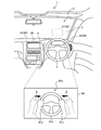
図1に示すように、本実施形態に係る運転支援方法は、例えば自動車などの車両1に搭載された運転支援装置30によって実行される。車両1には、運転支援装置30に加え、表示装置40が搭載される。
As shown in FIG. 1, the driving support method according to the present embodiment is executed by a
表示装置40は、複数であるが、これに限定されるものではない。なお、図1に示す例では、表示装置40は3つであるが、これに限られず、例えば2つ以下または4つ以上であってもよい。
The number of
複数の表示装置40はそれぞれ、例えばナビゲーションやオーディオなどに関する情報、車速等の運転状況に関する情報など種々の情報を表示可能なディスプレイである。例えば、複数の表示装置40は、ヘッドアップディスプレイ41(以下、「HUD(Head-Up Display)41」と記載する場合がある)と、メータディスプレイ42と、センタディスプレイ43とを含む。
Each of the plurality of
HUD41は、車室2内の適宜位置に取り付けられ、例えば車両1前方のフロントガラス3に情報を含む画像を映し出す。これにより、HUD41は、運転中のドライバ(ユーザ)の視野内に情報を表示することができる。
The
メータディスプレイ42およびセンタディスプレイ43は、例えばインストルメントパネル4に取り付けられ、各種情報を表示する。具体的には、メータディスプレイ42はインストルメントパネル4においてハンドル5の背面側であって運転席の正面付近に取り付けられる。センタディスプレイ43はインストルメントパネル4の中央付近で、運転席と助手席との間に対応する位置に取り付けられる。なお、上記したHUD41、メータディスプレイ42およびセンタディスプレイ43の取付位置は、あくまでも例示であって限定されるものではない。
The
運転支援装置30は、複数の表示装置40の制御などを行うとともに、ドライバの運転を支援する制御を行う。ここで、ドライバの運転を支援する制御とは、例えばドライバの運転操作を要しない自動運転の制御である。なお、かかる自動運転には、図示しない前方車両との車間距離を一定に保つように車両1を制御する「クルーズ運転」や、走行している車線を維持するように車両1を制御する「レーンキープ運転」などその他の種類の運転支援制御が含まれていてもよい。運転支援装置30の詳しい構成については、図2を参照して後述する。
The
ところで、運転支援装置30は、例えば車両1が所定の高速道路を走行しているなど、自動運転を行う条件が満たされた場合に自動運転を実行する一方、条件が満たされない場合に手動運転を実行する。従って、自動運転が解除されると、車両1の運転状態は手動運転へ切り替わることから、ドライバは、手動運転に切り替わる前に、ハンドル5を握るなどの運転準備動作を行う必要がある。
By the way, the
そこで、本実施形態に係る運転支援装置30にあっては、車両1の状態が自動運転から手動運転へ切り替わることを、事前にドライバに対して効果的に認識させることができ、ドライバに運転準備動作を促すことのできる構成とした。以下、かかる構成について詳しく説明する。
Therefore, in the
図1に示すように、運転支援装置30は、車両1の運転状態が自動運転から手動運転へ切り替えられる前に、ドライバに対してハンドル5を握るように誘導する誘導画像61aを、複数の表示装置40うちの例えばメータディスプレイ42に表示させる。
As shown in FIG. 1, the
誘導画像61aには、例えばハンドル5を模したハンドル画像61bと、ドライバの手を模した手画像61cとが含まれる。なお、図1にあっては、ハンドル画像61bを握る前の手画像61cを二点鎖線で示す一方、ハンドル画像61bを握った状態の手画像61cを実線で示している。
The
そして、運転支援装置30は、矢印Aで示すように、誘導画像61aにおいて、手画像61cを二点鎖線の位置から実線の位置まで移動させる。このように、誘導画像61aは、手画像61cがハンドル画像61bを握るような動作を示す画像を含むことから、ドライバに対し、手動運転に備えてハンドル5を握る運転準備動作が必要であることを、直感的に把握させることが可能となる。
Then, as shown by the arrow A, the
このように、運転支援装置30は、誘導画像61aを表示させることで、自動運転から手動運転へ切り替わることを、事前にドライバに対して効果的に認識させることができるとともに、ハンドル5を握る運転準備動作を促すことができる。
In this way, by displaying the
<2.運転支援装置を備えた運転支援システムの構成>
次に、図2を用いて、実施形態に係る運転支援装置30を備えた運転支援システム100の構成を説明する。図2は、実施形態における運転支援システム100の構成例を示すブロック図である。なお、図2では、本実施形態の特徴を説明するために必要な構成要素のみを機能ブロックで表しており、一般的な構成要素についての記載を省略している。
<2. Configuration of driving support system equipped with driving support device>
Next, the configuration of the
換言すれば、図2に図示される各構成要素は機能概念的なものであり、必ずしも物理的に図示の如く構成されていることを要しない。例えば、各機能ブロックの分散・統合の具体的形態は図示のものに限られず、その全部または一部を、各種の負荷や使用状況などに応じて、任意の単位で機能的または物理的に分散・統合して構成することが可能である。 In other words, each component shown in FIG. 2 is a functional concept and does not necessarily have to be physically configured as shown. For example, the specific form of distribution / integration of each functional block is not limited to the one shown in the figure, and all or part of it is functionally or physically distributed in any unit according to various loads and usage conditions. -It is possible to integrate and configure.
図2に示すように、運転支援システム100は、車両制御装置10と、運転支援装置30と、表示装置40と、車載センサ群71と、自動運転ボタン72と、撮像部73と、スピーカ74と、ハンドルセンサ75と、エンジン制御装置81と、ブレーキ制御装置82と、操舵機構制御装置83とを備える。
As shown in FIG. 2, the driving
表示装置40は、上記したようにHUD41と、メータディスプレイ42と、センタディスプレイ43とを含むが、これに限られず、例えば車室2(図1参照)の天井に取り付けられるディスプレイなどその他の表示装置を含んでもよい。
As described above, the
車載センサ群71には、車両1の走行制御に必要な情報を検出する各種のセンサが含まれる。例えば、車載センサ群71には、車速を検出する車速センサ、アクセル操作量を検出するアクセルセンサ、ブレーキ操作量を検出するブレーキセンサ、ハンドル5の操舵角を検出する操舵角センサなどが含まれる。 The in-vehicle sensor group 71 includes various sensors that detect information necessary for traveling control of the vehicle 1. For example, the vehicle-mounted sensor group 71 includes a vehicle speed sensor that detects a vehicle speed, an accelerator sensor that detects an accelerator operation amount, a brake sensor that detects a brake operation amount, a steering angle sensor that detects the steering angle of the handle 5.
また、車載センサ群71には、車両1の自動運転など運転支援制御に必要な情報を検出する各種の機器も含まれる。例えば、車載センサ群71には、GPS(Global Positioning System)衛星からの信号に基づいて自車の現在位置を検出するGPS受信機、他の車両などの対象物に電磁波を放射して得られた反射波から対象物までの距離や方向を測定するレーダ、車両1の外方(周辺)に存在する他の車両などの対象物を撮像するカメラなどが含まれる。 Further, the in-vehicle sensor group 71 also includes various devices that detect information necessary for driving support control such as automatic driving of the vehicle 1. For example, the in-vehicle sensor group 71 is obtained by radiating electromagnetic waves to an object such as a GPS receiver that detects the current position of the own vehicle based on a signal from a GPS (Global Positioning System) satellite or another vehicle. It includes a radar that measures the distance and direction from the reflected wave to the object, a camera that captures an object such as another vehicle existing outside (periphery) of the vehicle 1, and the like.
なお、車載センサ群71は、上記した各種機器に限定されるものではなく、例えば、他の車両との間で各種情報(例えば車速など)を送受信する車車間通信機、路肩に設置される通信機との間で各種情報(例えば走行している道路の工事情報など)を送受信する路車間通信機などその他の機器を含んでいてもよい。 The in-vehicle sensor group 71 is not limited to the above-mentioned various devices, for example, an inter-vehicle communication device for transmitting and receiving various information (for example, vehicle speed) with other vehicles, and communication installed on the shoulder of the road. It may include other devices such as a road-to-vehicle communication device that transmits and receives various information (for example, construction information of a traveling road) to and from the machine.
上記した車載センサ群71は、得られた車速や自車位置などを示す信号を車両制御装置10および運転支援装置30へ出力する。
The vehicle-mounted sensor group 71 described above outputs signals indicating the obtained vehicle speed, own vehicle position, and the like to the
自動運転ボタン72は、車室2(図1参照)内のドライバによって操作可能な位置に配置される。自動運転ボタン72は、ドライバによる操作に応じて、自動運転の開始要求を示す信号や、自動運転の解除要求を示す信号を運転支援装置30へ出力する。
The
撮像部73は、車室2(図1参照)の適宜位置に設けられ、ドライバを撮像する。撮像部73は、後述するように、ドライバの視線検出やドライバのハンドル5に対する動作の検出に利用されるため、ドライバの顔や手を含む画像を撮像し、かかる画像情報を運転支援装置30へ出力する。なお、撮像部73としては、車載カメラなどを用いることができる。
The
スピーカ74は、車室2(図1参照)の適宜位置に配置される。そして、スピーカ74は、後述するドライバへの通知に関する音声を出力する。 The speaker 74 is arranged at an appropriate position in the vehicle interior 2 (see FIG. 1). Then, the speaker 74 outputs a voice regarding the notification to the driver, which will be described later.
ハンドルセンサ75は、例えばハンドル5(図1参照)に取り付けられる。ハンドルセンサ75は、後述するように、ハンドル5がドライバによって握られたか否かの判定に利用される。そのため、ハンドルセンサ75としては、ハンドル5を握ったときのドライバの脈拍や血圧、発汗などを検出可能なバイタルセンサを用いることができる。
The
なお、ハンドルセンサ75は、上記したバイタルセンサに限定されるものではなく、例えばドライバによって把持される際にハンドル5に作用する圧力を検出可能な圧力センサや、ハンドル5に対するドライバの接触を検出可能な接触センサなど、ドライバによるハンドル5の把持を検出できればその他の種類のセンサであってもよい。
The
車両制御装置10は、車両制御部11を備える。車両制御部11は、車両1の走行制御を行う。詳しくは、例えばドライバからアクセルやブレーキ(いずれも不図示)、ハンドル5に対して運転操作がなされると、車載センサ群71のアクセルセンサやブレーキセンサ、操舵角センサは、各種の信号を車両制御部11へ出力する。
The
車両制御部11は、かかる信号に基づいてエンジン制御装置81、ブレーキ制御装置82および操舵機構制御装置83を制御して、車両1の走行制御を行う。なお、上記したエンジン制御装置81はエンジンを制御する装置、ブレーキ制御装置82はブレーキを制御する装置、操舵機構制御装置83は車両1を操舵する操舵機構を制御する装置である。 The vehicle control unit 11 controls the engine control device 81, the brake control device 82, and the steering mechanism control device 83 based on the signal to control the running of the vehicle 1. The engine control device 81 described above is a device for controlling the engine, the brake control device 82 is a device for controlling the brake, and the steering mechanism control device 83 is a device for controlling the steering mechanism for steering the vehicle 1.
運転支援装置30は、制御部50と、記憶部60とを備える。制御部50は、運転切替部51と、視線検出部52と、動作検出部53と、把持判定部54と、表示制御部55と、通知制御部56とを備え、CPU(Central Processing Unit)などを有するマイクロコンピュータである。
The driving
また、記憶部60は、不揮発性メモリやハードディスクドライブといった記憶デバイスで構成される記憶部であり、画像情報61を記憶する。画像情報61には、上記した誘導画像61a(図1参照)に関する情報が含まれる。画像情報61には、誘導画像61aに加え、視線誘導画像61d(図3参照)、車両画像61e、道路画像61fおよび車室画像61g(いずれも図5参照)などに関する情報も含まれるが、これら各種の画像については後述する。
Further, the storage unit 60 is a storage unit composed of a storage device such as a non-volatile memory or a hard disk drive, and stores image information 61. The image information 61 includes information regarding the above-mentioned guided
運転切替部51は、車両1の運転状態を自動運転と手動運転との間で切り替える。例えば、運転切替部51は、自動運転ボタン72から自動運転の開始要求を示す信号が入力されたり、車両1が所定の高速道路を走行していたり、自動運転を行う条件が満たされた場合に、車両1の運転状態を自動運転に切り替える。運転切替部51は、例えば車載センサ群71から出力されるGPSの情報やレーダの情報等に基づき、車両制御部11を介してエンジン制御装置81等を制御し、自動運転などの運転支援制御を実行する。
The
また、例えば、運転切替部51は、自動運転を行う条件が満たされない場合に、車両1の運転状態を自動運転から手動運転へ切り替える。運転切替部51は、手動運転に実際に切り替える前に、現在の時刻から手動運転へ切り替わるまでの時間、および、現在の位置から手動運転へ切り替わる地点までの距離に関する情報を表示制御部55へ出力する。なお、以下では、手動運転へ切り替わるまでの時間を「残時間」、手動運転へ切り替わる地点までの距離を「残距離」と記載する場合がある。
Further, for example, the
運転切替部51は、手動運転への切り替え前に、ドライバが正常に手動運転を行うことができるか否かを判定し、正常に運転できないと判定された場合、車両1を路肩やサービスエリアなどの安全な場所に自動停車させるようにしてもよい。
The
なお、ドライバが正常に運転できるか否かの判定は、例えば手動運転への切り替え前に、車両1がカーブに進入するような場面で、ドライバがカーブに倣ったハンドル操作ができているか否かで行うが、これに限定されるものではない。 Whether or not the driver can drive normally is determined by whether or not the driver can operate the steering wheel following the curve, for example, in a situation where the vehicle 1 enters a curve before switching to manual driving. However, it is not limited to this.
視線検出部52は、撮像部73によって撮像されたドライバの画像を取得し、かかる画像に対する画像解析処理を行ってドライバの視線を検出する。例えば、視線検出部52は、ドライバの画像におけるドライバの頭部の向きや目の位置を、予め記憶部60に記憶された基準画像と比較し、ドライバの視線が何処に向いているかを検出してもよい。
The line-of-sight detection unit 52 acquires an image of the driver captured by the
なお、例えば、撮像部73が赤外線カメラおよび赤外線LEDを備えるように構成し、視線検出部52は、赤外線カメラで撮像した画像に基づいてドライバの視線を検出してもよい。具体的には、視線検出部52は、赤外線LEDで照らしたドライバの顔を赤外線カメラで撮像することによって得られる赤外画像中の瞳孔と、眼球上に生じる赤外照明反射像との位置関係に基づき、ドライバの視線を検出してもよい。
For example, the
そして、視線検出部52は、検出されたドライバの視線を示す情報を表示制御部55へ出力する。なお、上記したドライバの視線を検出する手法は、あくまでも例示であって限定されるものではない。
Then, the line-of-sight detection unit 52 outputs information indicating the line of sight of the detected driver to the
動作検出部53は、ドライバのハンドル5に対する動作を検出する。例えば、動作検出部53は、撮像部73によって撮像されたドライバの画像を取得し、かかる画像に対する画像解析処理を行い、ドライバのハンドル5に対して手を近づける動作を検出する。
The
動作検出部53は、ドライバのハンドル5に対して手を近づける動作を検出すると、ハンドル5に対するドライバの手の位置など、ハンドル5に対する動作を示す情報を表示制御部55へ出力する。
When the
把持判定部54は、例えばハンドルセンサ75の出力に基づいてハンドル5がドライバによって握られたか否かを判定する。例えば、ハンドルセンサ75がバイタルセンサである場合、把持判定部54は、ハンドルセンサ75によってドライバの脈拍等が検出されているときにハンドル5がドライバによって握られたと判定することができる。そして、把持判定部54は、判定結果を示す情報を表示制御部55へ出力する。
The
表示制御部55は、上記したように、車両1の運転状態が自動運転から手動運転へ切り替えられる前に、ハンドル5を握るように誘導する誘導画像61aを表示装置40に表示させる。
As described above, the
ここで、表示制御部55は、複数の表示装置40のうち、実際のハンドル5の背面側に配置されるメータディスプレイ42に誘導画像61aを表示させることができる。これにより、表示制御部55は、誘導画像61aに含まれるハンドル画像61bを、実際のハンドル5付近に表示できることから、ドライバに対し、手動運転に備えてハンドル5を握る運転準備動作が必要であることを、より直感的に把握させることが可能となる。
Here, the
なお、表示制御部55は、誘導画像61aを、メータディスプレイ42に代えて、あるいは加えて、HUD41やセンタディスプレイ43に表示させてもよい。
The
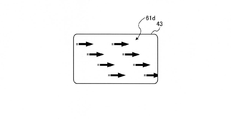
また、表示制御部55は、ドライバがメータディスプレイ42を見ていないと推定される場合、ドライバの視線をメータディスプレイ42へ誘導する視線誘導画像61d(図3参照)を表示装置40に表示させてもよい。図3は、視線誘導画像61dの一例を説明する図である。
Further, when it is estimated that the driver is not looking at the
例えば、表示制御部55は、視線検出部52によってドライバの視線がメータディスプレイ42とは異なる表示装置40(ここではセンタディスプレイ43)にあることが検出された場合、図3に示すように、センタディスプレイ43に視線誘導画像61dを表示させる。
For example, when the
視線誘導画像61dには、例えば、ドット柄がセンタディスプレイ43からメータディスプレイ42へ向かって流れるような動きの画像が含まれてもよい。そして、ドライバは、かかるドット柄の動きを目で追うと、視線が自然にセンタディスプレイ43からメータディスプレイ42へ向くこととなる。すなわち、視線誘導画像61dによってドライバの視線をメータディスプレイ42へ誘導することができる。
The line-of-
このように、表示制御部55は、視線検出部52によって視線が複数の表示装置40のうち誘導画像61aを表示させるメータディスプレイ42とは別のセンタディスプレイ43(別の表示装置の一例)にあることが検出された場合、視線誘導画像61dをセンタディスプレイ43に表示させる。これにより、ドライバの視線を、誘導画像61aが表示されるメータディスプレイ42へ誘導することができる。
As described above, the
さらに、表示制御部55は、効果音をスピーカ74から出力させてもよい。かかる効果音としては、例えばセンタディスプレイ43からメータディスプレイ42へ向かって流れるような効果音(例えば、キラキラやサラサラ等の音)を用いることができる。これにより、ドライバの視線を、誘導画像61aが表示されるメータディスプレイ42へより一層誘導することができる。
Further, the
なお、図示は省略するが、表示制御部55は、視線検出部52によってドライバの視線がHUD41にあることが検出された場合、視線誘導画像61dをHUD41に表示させ、ドライバの視線をメータディスプレイ42へ誘導してもよい。
Although not shown, the
なお、視線誘導画像61dは、図3に示す例に限定されるものではない。図4は、視線誘導画像61dの変形例を説明する図である。図4に示すように、変形例に係る視線誘導画像61dには、例えば、矢印柄がセンタディスプレイ43からメータディスプレイ42(図4で図示せず)へ向かって流れるような動きの画像が含まれてもよい。これにより、図3に示す視線誘導画像61dと同様、ドライバの視線をセンタディスプレイ43からメータディスプレイ42へ誘導することができる。また、視線誘導画像61dには、例えば「メータディスプレイを見て下さい」など、視線を誘導するような文章を示す画像が含まれてもよい。
The line-of-
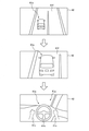
また、表示制御部55は、誘導画像61aを表示させる前に、手動運転が開始されることをドライバに想起させるような画像をメータディスプレイ42に表示させてもよい。図5は、手動運転の開始をドライバに想起させる画像の一例を示す図である。
Further, the
図5の上段に示すように、表示制御部55は、先ず車両1(図1参照)の外観を模した車両画像61eをメータディスプレイ42に表示させる。なお、車両画像61eは、車両1を斜め後ろ上方から見たときの俯瞰画像である。かかる車両画像61eは、走行中の道路を模した道路画像61fと組み合わせてもよい。
As shown in the upper part of FIG. 5, the
そして、図5の中段に示すように、表示制御部55は、視点が車両画像61eに徐々に近づく画像を表示させ、最終的には、図5の下段に示すように、車室2(図1参照)を模した車室画像61gをメータディスプレイ42に表示させる。なお、図5に示すように、表示制御部55は、車室画像61gに誘導画像61aを組み合わせて表示させてもよい。
Then, as shown in the middle part of FIG. 5, the
このように、表示制御部55は、車両画像61eから徐々に車室画像61gへ遷移する画像を表示させることで、あたかもドライバが車両1の後方から運転席に滑り込むようなイメージを表示できる。これにより、表示制御部55は、手動運転が開始されることをドライバに想起させることができ、結果としてハンドル5を握る運転準備動作をドライバに対して効果的に促すことができる。
In this way, the
図6は、ハンドル画像61bの一例を示す図である。図6に示すように、表示制御部55は、ハンドル画像61bにおいてハンドル5の握る部位に対応する位置(把持位置)61ba付近を強調表示してもよい。なお、図6では、把持位置61baを破線で囲んで示している。
FIG. 6 is a diagram showing an example of the
例えば、表示制御部55は、ハンドル画像61bにおける把持位置61ba付近を、発光させたり、点滅させたり、色を変えたりするなどして、強調表示してもよい。これにより、表示制御部55は、把持位置61baを注視され易くすることができ、よってドライバに対してハンドル5を握る運転準備動作を効果的に促すことができる。
For example, the
また、表示制御部55は、動作検出部53によって検出されたドライバのハンドル5に対する動作に基づいて、誘導画像61aを変化させるようにしてもよい。例えば、表示制御部55は、動作検出部53によってドライバのハンドル5に対して手を近づける動作が検出された場合、図1に矢印Aで示すように、誘導画像61aにおいて手画像61cをハンドル画像61bに近づけるように表示してもよい。
Further, the
このように、表示制御部55は、手画像61cを、ドライバの手の動作に同期、または略同期させて表示することで、ドライバに対してハンドル5を握る運転準備動作をより効果的に促すことができる。
In this way, the
また、表示制御部55は、ドライバのハンドル5に対する把持状態に応じてハンドル画像61bを変化させてもよい。例えば、表示制御部55は、把持判定部54によってハンドル5がドライバによって握られたと判定された場合、ハンドル画像61bを変化させてもよい。具体的には、表示制御部55は、ハンドル画像61bの色を、ハンドル5が握られる前が赤色で、握られた後が青色に変更するなどしてもよい。これにより、表示制御部55は、ハンドル5が確実に把持されて運転準備動作ができていることを、ドライバに対して認識させることができる。
Further, the
なお、ハンドル画像61bの変化としては、上記した色の変化に限られず、例えば、表示制御部55は、ハンドル5が握られる前に点滅して表示させていたハンドル画像61bを、握られた後に点滅しないハンドル画像61bに変化させるなどしてもよい。
The change in the
また、表示制御部55は、運転切替部51の出力によって取得した、手動運転へ切り替わるまでの残時間の情報や残距離の情報を示す画像を表示装置40に表示させてもよい。例えば、図示は省略するが、表示制御部55は、残時間の情報を「自動運転の解除まであと90秒」など、カウントダウンしていく画像をHUD41に表示させてもよい。なお、残時間の情報が表示される表示装置40は、上記したHUD41に限られず、メータディスプレイ42やセンタディスプレイ43などであってもよい。
Further, the
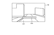
図7は、残距離の情報を示す画像の一例を示す図である。図7に示すように、表示制御部55は、走行中の道路を模した道路画像61fに、ゴールテープを模したゴール画像61hを組み合わせることで、残距離の情報を表示してもよい。なお、ゴール画像61hは、道路画像61fにおいて手動運転に切り替わる地点に対応する位置に表示される。
FIG. 7 is a diagram showing an example of an image showing information on the remaining distance. As shown in FIG. 7, the
これにより、表示制御部55は、手動運転へ切り替わるタイミングをドライバに対して効果的に把握させることができる。
As a result, the
通知制御部56は、車両1の運転状態が自動運転から手動運転へ切り替わることをユーザに対して通知する。例えば、通知制御部56は、運転切替部51によって車両1の運転状態が自動運転から手動運転へ切り替えられる前に、「自動運転が解除されます。ハンドルを握って下さい」などの音声をスピーカ74を介して出力することで、ユーザへの通知を行う。これにより、通知制御部56は、自動運転から手動運転へ切り替わることを、事前にドライバに対して効果的に認識させることができる。
The notification control unit 56 notifies the user that the driving state of the vehicle 1 is switched from automatic driving to manual driving. For example, the notification control unit 56 emits a voice such as "automatic driving is canceled. Please hold the steering wheel" to the speaker 74 before the driving state of the vehicle 1 is switched from automatic driving to manual driving by the
また、通知制御部56は、ドライバが横を向いているなど、視線検出部52によってドライバの視線が車両1の前方を向いていないことが検出された場合、例えば車室2の後方から前方へ向かって流れるような効果音をスピーカ74から出力してもよい。また、表示制御部55は、ドライバの視線が車両1の前方を向いていないことが検出された場合、メータディスプレイ42からHUD41へ視線を誘導する視線誘導画像61dを、メータディスプレイ42に表示させてもよい。これにより、ドライバに対して車両1の前方を向くように促すことができる。
Further, when the line-of-sight detection unit 52 detects that the driver's line of sight is not facing the front of the vehicle 1, such as when the driver is facing sideways, the notification control unit 56 moves from the rear to the front of the
また、通知制御部56は、例えば視線検出部52によって視線が検出されず、ドライバが居眠りをしていると推定される場合、警報音をスピーカ74から出力してもよい。さらに、通知制御部56は、運転席に取り付けられたアクチュエータ(図示せず)を作動させて、運転席の背もたれを起したり、運転席を振動させたりすることで、ハンドル5を握る運転準備動作を行うようドライバに促してもよい。 Further, the notification control unit 56 may output an alarm sound from the speaker 74, for example, when the line of sight is not detected by the line of sight detection unit 52 and it is estimated that the driver is dozing. Further, the notification control unit 56 operates an actuator (not shown) attached to the driver's seat to raise the backrest of the driver's seat or vibrate the driver's seat to prepare for driving to grip the steering wheel 5. You may urge the driver to do the action.
なお、通知制御部56は、ドライバが居眠りをしていると推定される場合、上記したユーザへの音声での通知を、ドライバが起きている場合と比べて早期に行うようにしてもよい。 When it is presumed that the driver is dozing, the notification control unit 56 may perform the above-mentioned voice notification to the user earlier than when the driver is awake.
<3.実施形態に係る運転支援装置の制御処理>
次に、運転支援装置30による具体的な処理手順について図8を用いて説明する。図8は、運転支援装置30が実行する処理手順を示すフローチャートである。
<3. Control processing of the driving support device according to the embodiment>
Next, a specific processing procedure by the driving
図8に示すように、運転支援装置30の制御部50は、車両1の運転状態が自動運転であるか否かを判定する(ステップS10)。制御部50は、車両1の運転状態が自動運転ではないと判定された場合(ステップS10,No)、以降の処理をスキップする。
As shown in FIG. 8, the control unit 50 of the driving
一方、制御部50は、車両1の運転状態が自動運転であると判定された場合(ステップS10,Yes)、例えば自動運転を行う条件が満たされなくなったなどで、運転状態が自動運転から手動運転へ切り替わるか否かを判定する(ステップS11)。 On the other hand, when the driving state of the vehicle 1 is determined to be automatic driving (step S10, Yes), the control unit 50 manually changes the driving state from automatic driving, for example, when the condition for performing automatic driving is no longer satisfied. It is determined whether or not to switch to the operation (step S11).
制御部50は、手動運転へ切り替わらないと判定された場合(ステップS11,No)、すなわち、自動運転が継続される場合、ステップS11の処理を繰り返す。一方、制御部50は、手動運転へ切り替わると判定された場合(ステップS11,Yes)、ドライバの視線がメータディスプレイ42にあるか否かを判定する(ステップS12)。 The control unit 50 repeats the process of step S11 when it is determined that the operation is not switched to the manual operation (steps S11, No), that is, when the automatic operation is continued. On the other hand, when it is determined that the operation is switched to the manual operation (step S11, Yes), the control unit 50 determines whether or not the driver's line of sight is on the meter display 42 (step S12).
制御部50は、視線がメータディスプレイ42にないと判定された場合(ステップS12,No)、視線誘導画像61dを例えば視線が向いている表示装置40に表示させる(ステップS13)。
When it is determined that the line of sight is not on the meter display 42 (step S12, No), the control unit 50 displays the line-of-
制御部50は、視線がメータディスプレイ42にあると判定された場合(ステップS12,Yes)、または、ステップS13の処理で視線誘導画像61dを表示させた後、誘導画像61aをメータディスプレイ42に表示させる(ステップS14)。
When the control unit 50 determines that the line of sight is on the meter display 42 (steps S12, Yes), or after displaying the line-of-
次いで、制御部50は、残時間や残距離を示す情報を表示装置40に表示させる(ステップS15)。そして、制御部50は、ハンドル5がドライバによって握られたか否かを判定する(ステップS16)。制御部50は、ハンドル5が握られていないと判定された場合(ステップS16,No)、ステップS16の処理を繰り返す。
Next, the control unit 50 causes the
一方、制御部50は、ハンドル5が握られたと判定された場合(ステップS16,Yes)、ハンドル画像61bを変化させる(ステップS17)。続いて、制御部50は、手動運転への切り替え前に、ドライバが正常に手動運転を行うことができるか否かを判定する(ステップS18)。
On the other hand, when it is determined that the handle 5 is gripped (step S16, Yes), the control unit 50 changes the
制御部50は、正常に手動運転を行うことができると判定された場合(ステップS18,Yes)、車両1の運転状態を自動運転から手動運転へ切り替える(ステップS19)。他方、制御部50は、正常に手動運転を行うことができないと判定された場合(ステップS18,No)、車両1を路肩等の安全場所に自動停止させる(ステップS20)。 When the control unit 50 determines that the manual driving can be normally performed (step S18, Yes), the control unit 50 switches the driving state of the vehicle 1 from the automatic driving to the manual driving (step S19). On the other hand, when it is determined that the manual operation cannot be normally performed (step S18, No), the control unit 50 automatically stops the vehicle 1 at a safe place such as a road shoulder (step S20).
上述してきたように、実施形態に係る運転支援装置30は、運転切替部51と、表示制御部55とを備える。運転切替部51は、車両1の運転状態を自動運転から手動運転へ切り替える。表示制御部55は、運転切替部51によって車両1の運転状態が自動運転から手動運転へ切り替えられる前に、ドライバに対してハンドル5を握るように誘導する誘導画像61aを表示装置40に表示させる。これにより、車両1の状態が自動運転から手動運転へ切り替わることを、事前にドライバに対して効果的に認識させることができ、ドライバに運転準備動作を促すことができる。
As described above, the
さらなる効果や変形例は、当業者によって容易に導き出すことができる。このため、本発明のより広範な態様は、以上のように表しかつ記述した特定の詳細および代表的な実施形態に限定されるものではない。したがって、添付の特許請求の範囲およびその均等物によって定義される総括的な発明の概念の精神または範囲から逸脱することなく、様々な変更が可能である。 Further effects and variations can be easily derived by those skilled in the art. For this reason, the broader aspects of the invention are not limited to the particular details and representative embodiments described and described above. Accordingly, various modifications can be made without departing from the spirit or scope of the general concept of the invention as defined by the appended claims and their equivalents.
30 運転支援装置
40 表示装置
41 ヘッドアップディスプレイ(HUD)
42 メータディスプレイ
43 センタディスプレイ
51 運転切替部
52 視線検出部
53 動作検出部
54 把持判定部
55 表示制御部
56 通知制御部
30
42
Claims (9)
前記運転切替部によって前記車両の運転状態が前記自動運転から前記手動運転へ切り替えられる前に、前記車両の外観を模した車両画像から前記車両の室内を模した車室画像へ遷移する画像であって、当該画像の視点が前記車両画像に徐々に近づく画像を表示装置に表示させる表示制御部と
を備えることを特徴とする運転支援装置。 A driving switching unit that switches the driving state of the vehicle from automatic driving to manual driving,
Before driving state of the vehicle is switched to the manual operation from the automatic operation by the operation switching unit, the external appearance of the vehicle from the vehicle image simulating the vehicle compartment image indoor imitating the vehicle Qian Utsusuru image A driving support device comprising a display control unit for displaying an image in which the viewpoint of the image gradually approaches the vehicle image on the display device.
前記車両画像から前記車室画像へ遷移する画像を表示させた後、ドライバに対してハンドルを握るように誘導する誘導画像を前記表示装置に表示させること
を特徴とする請求項1に記載の運転支援装置。 The display control unit
The operation according to claim 1, wherein the display device displays a guidance image that guides the driver to hold the steering wheel after displaying an image that transitions from the vehicle image to the vehicle interior image. Support device.
前記ハンドルを模したハンドル画像と、前記ハンドル画像を握る動作を示す画像とを含むこと
を特徴とする請求項2に記載の運転支援装置。 The guided image is
The driving support device according to claim 2, further comprising a steering wheel image imitating the steering wheel and an image showing an operation of gripping the steering wheel image.
前記ハンドル画像において前記ハンドルの握る部位に対応する位置付近を強調表示すること
を特徴とする請求項3に記載の運転支援装置。 The display control unit
The driving support device according to claim 3, wherein the vicinity of the position corresponding to the gripped portion of the steering wheel is highlighted in the steering wheel image.
を備え、
前記表示制御部は、
前記動作検出部によってドライバの前記ハンドルに対して手を近づける動作が検出された場合、前記誘導画像においてドライバの手を模した手画像を前記ハンドル画像に近づけるように表示すること
を特徴とする請求項3または4に記載の運転支援装置。 It is equipped with an operation detection unit that detects the operation of the driver with respect to the handle.
The display control unit
When the motion detecting unit detects an action of bringing the driver's hand closer to the steering wheel, the claim is characterized in that a hand image imitating the driver's hand is displayed in the guidance image so as to be closer to the steering wheel image. Item 3. The driving support device according to Item 3.
を備え、
前記表示制御部は、
前記把持判定部によって前記ハンドルがドライバによって握られたと判定された場合、前記ハンドル画像を変化させること
を特徴とする請求項3〜5のいずれか一つに記載の運転支援装置。 A grip determination unit for determining whether or not the handle is gripped by the driver is provided.
The display control unit
The driving support device according to any one of claims 3 to 5, wherein when the grip determination unit determines that the steering wheel is gripped by the driver, the steering wheel image is changed.
ドライバの視線を検出する視線検出部
を備え、
前記表示制御部は、
前記視線検出部によって前記視線が前記複数の表示装置のうち前記誘導画像を表示させる表示装置とは別の表示装置にあることが検出された場合、前記別の表示装置から前記誘導画像を表示させる表示装置へ視線を誘導する視線誘導画像を前記別の表示装置に表示させること
を特徴とする請求項2〜6のいずれか一つに記載の運転支援装置。 There are multiple display devices, and
Equipped with a line-of-sight detector that detects the driver's line of sight
The display control unit
When the line-of-sight detection unit detects that the line of sight is on a display device other than the display device that displays the guidance image among the plurality of display devices, the guidance image is displayed from the other display device. The driving support device according to any one of claims 2 to 6, wherein a line-of-sight guidance image for guiding the line of sight to the display device is displayed on the other display device.
前記車両の運転状態が前記自動運転から前記手動運転へ切り替わるまでの時間および距離の少なくともいずれかを含む情報を示す画像を前記表示装置に表示させること
を特徴とする請求項1〜7のいずれか一つに記載の運転支援装置。 The display control unit
One of claims 1 to 7, wherein the display device displays an image showing information including at least one of a time and a distance from the automatic driving to the manual driving of the driving state of the vehicle. The driving support device described in one.
前記運転切替工程によって前記車両の運転状態が前記自動運転から前記手動運転へ切り替えられる前に、前記車両の外観を模した車両画像から前記車両の室内を模した車室画像へ遷移する画像であって、当該画像の視点が前記車両画像に徐々に近づく画像を表示装置に表示させる表示制御工程と
を含むことを特徴とする運転支援方法。 A driving switching process that switches the driving state of the vehicle from automatic driving to manual driving,
Before the operating state of the vehicle by the operation switching step is switched to the manual operation from the automatic operation, the appearance of the vehicle from the vehicle image simulating the vehicle compartment image indoor imitating the vehicle Qian Utsusuru image A driving support method comprising a display control step of displaying an image in which the viewpoint of the image gradually approaches the vehicle image on a display device.
Priority Applications (2)
| Application Number | Priority Date | Filing Date | Title |
|---|---|---|---|
| JP2017127902A JP6976089B2 (en) | 2017-06-29 | 2017-06-29 | Driving support device and driving support method |
| US15/921,009 US20190004514A1 (en) | 2017-06-29 | 2018-03-14 | Driver assistance apparatus and driver assistance method |
Applications Claiming Priority (1)
| Application Number | Priority Date | Filing Date | Title |
|---|---|---|---|
| JP2017127902A JP6976089B2 (en) | 2017-06-29 | 2017-06-29 | Driving support device and driving support method |
Publications (3)
| Publication Number | Publication Date |
|---|---|
| JP2019010929A JP2019010929A (en) | 2019-01-24 |
| JP2019010929A5 JP2019010929A5 (en) | 2019-11-07 |
| JP6976089B2 true JP6976089B2 (en) | 2021-12-08 |
Family
ID=64734804
Family Applications (1)
| Application Number | Title | Priority Date | Filing Date |
|---|---|---|---|
| JP2017127902A Active JP6976089B2 (en) | 2017-06-29 | 2017-06-29 | Driving support device and driving support method |
Country Status (2)
| Country | Link |
|---|---|
| US (1) | US20190004514A1 (en) |
| JP (1) | JP6976089B2 (en) |
Families Citing this family (31)
| Publication number | Priority date | Publication date | Assignee | Title |
|---|---|---|---|---|
| DE102017215542A1 (en) * | 2017-09-05 | 2019-03-07 | Audi Ag | Method for operating a driver assistance system of a motor vehicle and motor vehicle |
| WO2019156955A1 (en) * | 2018-02-06 | 2019-08-15 | Cavh Llc | Connected automated vehicle highway systems and methods for shared mobility |
| JP7063167B2 (en) * | 2018-07-26 | 2022-05-09 | トヨタ自動車株式会社 | Display control device, vehicle display device, display control method and program |
| JP2020055348A (en) * | 2018-09-28 | 2020-04-09 | 本田技研工業株式会社 | Agent device, agent control method, and program |
| JP7192570B2 (en) * | 2019-02-27 | 2022-12-20 | 株式会社Jvcケンウッド | Recording/playback device, recording/playback method and program |
| JP7207137B2 (en) * | 2019-04-25 | 2023-01-18 | 株式会社デンソー | Display control device and display control system |
| WO2020230308A1 (en) * | 2019-05-15 | 2020-11-19 | 日産自動車株式会社 | Driving assistance method and driving assistance device |
| JP7047821B2 (en) * | 2019-07-18 | 2022-04-05 | トヨタ自動車株式会社 | Driving support device |
| WO2021014954A1 (en) * | 2019-07-24 | 2021-01-28 | 株式会社デンソー | Display control device and display control program |
| JP7173090B2 (en) * | 2019-07-24 | 2022-11-16 | 株式会社デンソー | Display control device and display control program |
| JP7431546B2 (en) * | 2019-09-25 | 2024-02-15 | 株式会社Subaru | Vehicle control device |
| US12522142B2 (en) | 2019-10-23 | 2026-01-13 | Sony Group Corporation | Display system, display device, display method, and mobile apparatus |
| JP7067540B2 (en) | 2019-10-23 | 2022-05-16 | トヨタ自動車株式会社 | Vehicle display device |
| JP7375735B2 (en) | 2020-01-17 | 2023-11-08 | 株式会社デンソー | Operation control device and HMI control device, and operation control program and HMI control program |
| JP7306333B2 (en) * | 2020-06-11 | 2023-07-11 | 株式会社デンソー | Image processing device |
| DE112020007491T5 (en) * | 2020-08-05 | 2023-08-10 | Mitsubishi Electric Corporation | NOTIFICATION DEVICE AND NOTIFICATION METHOD |
| JP7484590B2 (en) * | 2020-08-31 | 2024-05-16 | トヨタ自動車株式会社 | Vehicle display control device, vehicle display system, vehicle display control method, and vehicle display control program |
| JP7554089B2 (en) * | 2020-10-13 | 2024-09-19 | 株式会社東海理化電機製作所 | Control device, presentation system, and program |
| JP2022110439A (en) * | 2021-01-18 | 2022-07-29 | 株式会社東海理化電機製作所 | Control device |
| DE112022001805T5 (en) * | 2021-03-30 | 2024-02-29 | Denso Corporation | Automated driving control device, automated driving control program, presentation control device and presentation control program |
| CN112793522A (en) * | 2021-03-30 | 2021-05-14 | 重庆长安汽车股份有限公司 | Steering wheel hands-off monitoring and early warning method and system and automobile |
| WO2023286228A1 (en) * | 2021-07-15 | 2023-01-19 | 三菱電機株式会社 | Facial information registration assistance device |
| CN115892055A (en) * | 2021-08-23 | 2023-04-04 | 腾讯科技(深圳)有限公司 | Vehicle automatic driving processing method, device, electronic device and storage medium |
| KR20240052840A (en) * | 2021-09-13 | 2024-04-23 | 후아웨이 테크놀러지 컴퍼니 리미티드 | Method and apparatus for prompting status information of vehicle |
| JP7460964B2 (en) | 2021-10-28 | 2024-04-03 | パナソニックオートモーティブシステムズ株式会社 | Display control device, display control method, and program |
| JP7357041B2 (en) * | 2021-11-11 | 2023-10-05 | 本田技研工業株式会社 | Vehicle control system, vehicle control method, and program |
| US12397644B2 (en) | 2021-11-29 | 2025-08-26 | Nippon Seiki Co., Ltd. | Display control device, display device, and display control method |
| JP7793397B2 (en) * | 2022-01-31 | 2026-01-05 | 株式会社デンソーテン | Control device and control method |
| CN114523986A (en) * | 2022-02-28 | 2022-05-24 | 亿咖通(湖北)技术有限公司 | Automatic driving function level display method, electronic device and computer storage medium |
| EP4495910A4 (en) * | 2022-03-18 | 2025-04-09 | Nissan Motor Co., Ltd. | DRIVING ASSISTANCE METHOD AND DEVICE |
| CN117392649B (en) * | 2023-12-11 | 2024-02-27 | 武汉未来幻影科技有限公司 | Identification method and device for indicating operation of vehicle part and processing equipment |
Family Cites Families (15)
| Publication number | Priority date | Publication date | Assignee | Title |
|---|---|---|---|---|
| JP2010086486A (en) * | 2008-10-02 | 2010-04-15 | Honda Motor Co Ltd | Drive assistance device |
| US8260482B1 (en) * | 2010-04-28 | 2012-09-04 | Google Inc. | User interface for displaying internal state of autonomous driving system |
| JP5679449B2 (en) * | 2011-07-08 | 2015-03-04 | アルパイン株式会社 | In-vehicle system |
| DE102012201513A1 (en) * | 2012-02-02 | 2013-08-08 | Bayerische Motoren Werke Aktiengesellschaft | Warning device in a motor vehicle for warning a driver |
| DE102013002533A1 (en) * | 2013-02-13 | 2014-08-14 | Audi Ag | Method and device for displaying information of a system |
| DE102013012777A1 (en) * | 2013-07-31 | 2015-02-05 | Valeo Schalter Und Sensoren Gmbh | Method for using a communication terminal in a motor vehicle when activated autopilot and motor vehicle |
| DE102013110909A1 (en) * | 2013-10-01 | 2015-04-02 | Scania Cv Ab | Device for automatically driving a vehicle |
| DE102013110852A1 (en) * | 2013-10-01 | 2015-04-16 | Volkswagen Aktiengesellschaft | Method for a driver assistance system of a vehicle |
| JP6349833B2 (en) * | 2014-03-25 | 2018-07-04 | 日産自動車株式会社 | Information display device |
| JP2016090274A (en) * | 2014-10-30 | 2016-05-23 | トヨタ自動車株式会社 | Alarm apparatus, alarm system, and portable terminal |
| EP3040809B1 (en) * | 2015-01-02 | 2018-12-12 | Harman Becker Automotive Systems GmbH | Method and system for controlling a human-machine interface having at least two displays |
| KR101659034B1 (en) * | 2015-01-20 | 2016-09-23 | 엘지전자 주식회사 | Apparatus for switching driving mode of vehicle and method thereof |
| JP6558732B2 (en) * | 2015-04-21 | 2019-08-14 | パナソニックIpマネジメント株式会社 | Driving support method, driving support device, driving control device, vehicle, and driving support program using the same |
| JP6488989B2 (en) * | 2015-11-04 | 2019-03-27 | 株式会社デンソー | Vehicle display device |
| US10152822B2 (en) * | 2017-04-01 | 2018-12-11 | Intel Corporation | Motion biased foveated renderer |
-
2017
- 2017-06-29 JP JP2017127902A patent/JP6976089B2/en active Active
-
2018
- 2018-03-14 US US15/921,009 patent/US20190004514A1/en not_active Abandoned
Also Published As
| Publication number | Publication date |
|---|---|
| US20190004514A1 (en) | 2019-01-03 |
| JP2019010929A (en) | 2019-01-24 |
Similar Documents
| Publication | Publication Date | Title |
|---|---|---|
| JP6976089B2 (en) | Driving support device and driving support method | |
| JP7024806B2 (en) | Information presentation device | |
| US11492017B2 (en) | Information presentation device and information presentation method | |
| US11267480B2 (en) | Travel control apparatus and travel control method | |
| US10137907B2 (en) | Startup suggestion device and startup suggestion method | |
| CN107408349B (en) | Information presentation device and information presentation method | |
| JP4825868B2 (en) | Vehicle alarm device | |
| US10067341B1 (en) | Enhanced heads-up display system | |
| JP2018180594A (en) | Driving support device | |
| JP2020164056A (en) | Control devices, control methods and programs | |
| WO2007105792A1 (en) | Monitor and monitoring method, controller and control method, and program | |
| JP2018181269A (en) | Presentation control device, automatic driving control device, presentation control method and automatic driving control method | |
| JP7632235B2 (en) | Automatic driving control device and automatic driving control program | |
| JP2019043176A (en) | On-vehicle display device | |
| JP2019001314A (en) | Driving support equipment and control program | |
| WO2020250645A1 (en) | In-vehicle communication device, vehicle remote control system, communication method, and program | |
| JP7647810B2 (en) | Presentation control device and presentation control program | |
| CN110383361A (en) | Method and apparatus for reminding driver to start at optical signal equipment | |
| US10628689B2 (en) | Method and device for identifying the signaling state of at least one signaling device | |
| US20180297471A1 (en) | Support to handle an object within a passenger interior of a vehicle | |
| CN110114809B (en) | Method and apparatus for alerting driver to start at light signaling device with varying output function | |
| JP6914730B2 (en) | Driving support device and driving support method | |
| JP2019043175A (en) | Head-up display device | |
| JP7637238B2 (en) | Method for detecting and alerting to changed surroundings | |
| JP2017149273A (en) | In-vehicle device, vehicle system, and program |
Legal Events
| Date | Code | Title | Description |
|---|---|---|---|
| A521 | Request for written amendment filed |
Free format text: JAPANESE INTERMEDIATE CODE: A523 Effective date: 20190930 |
|
| A621 | Written request for application examination |
Free format text: JAPANESE INTERMEDIATE CODE: A621 Effective date: 20190930 |
|
| A977 | Report on retrieval |
Free format text: JAPANESE INTERMEDIATE CODE: A971007 Effective date: 20201015 |
|
| A131 | Notification of reasons for refusal |
Free format text: JAPANESE INTERMEDIATE CODE: A131 Effective date: 20201104 |
|
| A521 | Request for written amendment filed |
Free format text: JAPANESE INTERMEDIATE CODE: A523 Effective date: 20201224 |
|
| A131 | Notification of reasons for refusal |
Free format text: JAPANESE INTERMEDIATE CODE: A131 Effective date: 20210518 |
|
| A521 | Request for written amendment filed |
Free format text: JAPANESE INTERMEDIATE CODE: A523 Effective date: 20210715 |
|
| TRDD | Decision of grant or rejection written | ||
| A01 | Written decision to grant a patent or to grant a registration (utility model) |
Free format text: JAPANESE INTERMEDIATE CODE: A01 Effective date: 20211012 |
|
| A61 | First payment of annual fees (during grant procedure) |
Free format text: JAPANESE INTERMEDIATE CODE: A61 Effective date: 20211109 |
|
| R150 | Certificate of patent or registration of utility model |
Ref document number: 6976089 Country of ref document: JP Free format text: JAPANESE INTERMEDIATE CODE: R150 |
|
| R250 | Receipt of annual fees |
Free format text: JAPANESE INTERMEDIATE CODE: R250 |
|
| R250 | Receipt of annual fees |
Free format text: JAPANESE INTERMEDIATE CODE: R250 |