JP6975552B2 - Vehicle lighting - Google Patents
Vehicle lighting Download PDFInfo
- Publication number
- JP6975552B2 JP6975552B2 JP2017102638A JP2017102638A JP6975552B2 JP 6975552 B2 JP6975552 B2 JP 6975552B2 JP 2017102638 A JP2017102638 A JP 2017102638A JP 2017102638 A JP2017102638 A JP 2017102638A JP 6975552 B2 JP6975552 B2 JP 6975552B2
- Authority
- JP
- Japan
- Prior art keywords
- light
- optical system
- light source
- optical axis
- vehicle lamp
- Prior art date
- Legal status (The legal status is an assumption and is not a legal conclusion. Google has not performed a legal analysis and makes no representation as to the accuracy of the status listed.)
- Active
Links
Images


Classifications
-
- F—MECHANICAL ENGINEERING; LIGHTING; HEATING; WEAPONS; BLASTING
- F21—LIGHTING
- F21S—NON-PORTABLE LIGHTING DEVICES; SYSTEMS THEREOF; VEHICLE LIGHTING DEVICES SPECIALLY ADAPTED FOR VEHICLE EXTERIORS
- F21S41/00—Illuminating devices specially adapted for vehicle exteriors, e.g. headlamps
- F21S41/60—Illuminating devices specially adapted for vehicle exteriors, e.g. headlamps characterised by a variable light distribution
- F21S41/63—Illuminating devices specially adapted for vehicle exteriors, e.g. headlamps characterised by a variable light distribution by acting on refractors, filters or transparent cover plates
- F21S41/64—Illuminating devices specially adapted for vehicle exteriors, e.g. headlamps characterised by a variable light distribution by acting on refractors, filters or transparent cover plates by changing their light transmissivity, e.g. by liquid crystal or electrochromic devices
-
- F—MECHANICAL ENGINEERING; LIGHTING; HEATING; WEAPONS; BLASTING
- F21—LIGHTING
- F21S—NON-PORTABLE LIGHTING DEVICES; SYSTEMS THEREOF; VEHICLE LIGHTING DEVICES SPECIALLY ADAPTED FOR VEHICLE EXTERIORS
- F21S41/00—Illuminating devices specially adapted for vehicle exteriors, e.g. headlamps
- F21S41/10—Illuminating devices specially adapted for vehicle exteriors, e.g. headlamps characterised by the light source
- F21S41/14—Illuminating devices specially adapted for vehicle exteriors, e.g. headlamps characterised by the light source characterised by the type of light source
- F21S41/141—Light emitting diodes [LED]
- F21S41/147—Light emitting diodes [LED] the main emission direction of the LED being angled to the optical axis of the illuminating device
-
- F—MECHANICAL ENGINEERING; LIGHTING; HEATING; WEAPONS; BLASTING
- F21—LIGHTING
- F21S—NON-PORTABLE LIGHTING DEVICES; SYSTEMS THEREOF; VEHICLE LIGHTING DEVICES SPECIALLY ADAPTED FOR VEHICLE EXTERIORS
- F21S41/00—Illuminating devices specially adapted for vehicle exteriors, e.g. headlamps
- F21S41/10—Illuminating devices specially adapted for vehicle exteriors, e.g. headlamps characterised by the light source
- F21S41/14—Illuminating devices specially adapted for vehicle exteriors, e.g. headlamps characterised by the light source characterised by the type of light source
- F21S41/141—Light emitting diodes [LED]
- F21S41/143—Light emitting diodes [LED] the main emission direction of the LED being parallel to the optical axis of the illuminating device
-
- F—MECHANICAL ENGINEERING; LIGHTING; HEATING; WEAPONS; BLASTING
- F21—LIGHTING
- F21S—NON-PORTABLE LIGHTING DEVICES; SYSTEMS THEREOF; VEHICLE LIGHTING DEVICES SPECIALLY ADAPTED FOR VEHICLE EXTERIORS
- F21S41/00—Illuminating devices specially adapted for vehicle exteriors, e.g. headlamps
- F21S41/20—Illuminating devices specially adapted for vehicle exteriors, e.g. headlamps characterised by refractors, transparent cover plates, light guides or filters
- F21S41/25—Projection lenses
- F21S41/255—Lenses with a front view of circular or truncated circular outline
-
- F—MECHANICAL ENGINEERING; LIGHTING; HEATING; WEAPONS; BLASTING
- F21—LIGHTING
- F21S—NON-PORTABLE LIGHTING DEVICES; SYSTEMS THEREOF; VEHICLE LIGHTING DEVICES SPECIALLY ADAPTED FOR VEHICLE EXTERIORS
- F21S41/00—Illuminating devices specially adapted for vehicle exteriors, e.g. headlamps
- F21S41/20—Illuminating devices specially adapted for vehicle exteriors, e.g. headlamps characterised by refractors, transparent cover plates, light guides or filters
- F21S41/25—Projection lenses
- F21S41/265—Composite lenses; Lenses with a patch-like shape
-
- F—MECHANICAL ENGINEERING; LIGHTING; HEATING; WEAPONS; BLASTING
- F21—LIGHTING
- F21S—NON-PORTABLE LIGHTING DEVICES; SYSTEMS THEREOF; VEHICLE LIGHTING DEVICES SPECIALLY ADAPTED FOR VEHICLE EXTERIORS
- F21S41/00—Illuminating devices specially adapted for vehicle exteriors, e.g. headlamps
- F21S41/20—Illuminating devices specially adapted for vehicle exteriors, e.g. headlamps characterised by refractors, transparent cover plates, light guides or filters
- F21S41/25—Projection lenses
- F21S41/27—Thick lenses
-
- F—MECHANICAL ENGINEERING; LIGHTING; HEATING; WEAPONS; BLASTING
- F21—LIGHTING
- F21S—NON-PORTABLE LIGHTING DEVICES; SYSTEMS THEREOF; VEHICLE LIGHTING DEVICES SPECIALLY ADAPTED FOR VEHICLE EXTERIORS
- F21S41/00—Illuminating devices specially adapted for vehicle exteriors, e.g. headlamps
- F21S41/30—Illuminating devices specially adapted for vehicle exteriors, e.g. headlamps characterised by reflectors
- F21S41/32—Optical layout thereof
- F21S41/321—Optical layout thereof the reflector being a surface of revolution or a planar surface, e.g. truncated
-
- F—MECHANICAL ENGINEERING; LIGHTING; HEATING; WEAPONS; BLASTING
- F21—LIGHTING
- F21S—NON-PORTABLE LIGHTING DEVICES; SYSTEMS THEREOF; VEHICLE LIGHTING DEVICES SPECIALLY ADAPTED FOR VEHICLE EXTERIORS
- F21S41/00—Illuminating devices specially adapted for vehicle exteriors, e.g. headlamps
- F21S41/40—Illuminating devices specially adapted for vehicle exteriors, e.g. headlamps characterised by screens, non-reflecting members, light-shielding members or fixed shades
- F21S41/43—Illuminating devices specially adapted for vehicle exteriors, e.g. headlamps characterised by screens, non-reflecting members, light-shielding members or fixed shades characterised by the shape thereof
-
- F—MECHANICAL ENGINEERING; LIGHTING; HEATING; WEAPONS; BLASTING
- F21—LIGHTING
- F21S—NON-PORTABLE LIGHTING DEVICES; SYSTEMS THEREOF; VEHICLE LIGHTING DEVICES SPECIALLY ADAPTED FOR VEHICLE EXTERIORS
- F21S41/00—Illuminating devices specially adapted for vehicle exteriors, e.g. headlamps
- F21S41/50—Illuminating devices specially adapted for vehicle exteriors, e.g. headlamps characterised by aesthetic components not otherwise provided for, e.g. decorative trim, partition walls or covers
-
- F—MECHANICAL ENGINEERING; LIGHTING; HEATING; WEAPONS; BLASTING
- F21—LIGHTING
- F21S—NON-PORTABLE LIGHTING DEVICES; SYSTEMS THEREOF; VEHICLE LIGHTING DEVICES SPECIALLY ADAPTED FOR VEHICLE EXTERIORS
- F21S41/00—Illuminating devices specially adapted for vehicle exteriors, e.g. headlamps
- F21S41/60—Illuminating devices specially adapted for vehicle exteriors, e.g. headlamps characterised by a variable light distribution
- F21S41/63—Illuminating devices specially adapted for vehicle exteriors, e.g. headlamps characterised by a variable light distribution by acting on refractors, filters or transparent cover plates
- F21S41/64—Illuminating devices specially adapted for vehicle exteriors, e.g. headlamps characterised by a variable light distribution by acting on refractors, filters or transparent cover plates by changing their light transmissivity, e.g. by liquid crystal or electrochromic devices
- F21S41/645—Illuminating devices specially adapted for vehicle exteriors, e.g. headlamps characterised by a variable light distribution by acting on refractors, filters or transparent cover plates by changing their light transmissivity, e.g. by liquid crystal or electrochromic devices by electro-optic means, e.g. liquid crystal or electrochromic devices
-
- F—MECHANICAL ENGINEERING; LIGHTING; HEATING; WEAPONS; BLASTING
- F21—LIGHTING
- F21S—NON-PORTABLE LIGHTING DEVICES; SYSTEMS THEREOF; VEHICLE LIGHTING DEVICES SPECIALLY ADAPTED FOR VEHICLE EXTERIORS
- F21S41/00—Illuminating devices specially adapted for vehicle exteriors, e.g. headlamps
- F21S41/60—Illuminating devices specially adapted for vehicle exteriors, e.g. headlamps characterised by a variable light distribution
- F21S41/67—Illuminating devices specially adapted for vehicle exteriors, e.g. headlamps characterised by a variable light distribution by acting on reflectors
- F21S41/675—Illuminating devices specially adapted for vehicle exteriors, e.g. headlamps characterised by a variable light distribution by acting on reflectors by moving reflectors
-
- F—MECHANICAL ENGINEERING; LIGHTING; HEATING; WEAPONS; BLASTING
- F21—LIGHTING
- F21S—NON-PORTABLE LIGHTING DEVICES; SYSTEMS THEREOF; VEHICLE LIGHTING DEVICES SPECIALLY ADAPTED FOR VEHICLE EXTERIORS
- F21S45/00—Arrangements within vehicle lighting devices specially adapted for vehicle exteriors, for purposes other than emission or distribution of light
-
- F—MECHANICAL ENGINEERING; LIGHTING; HEATING; WEAPONS; BLASTING
- F21—LIGHTING
- F21V—FUNCTIONAL FEATURES OR DETAILS OF LIGHTING DEVICES OR SYSTEMS THEREOF; STRUCTURAL COMBINATIONS OF LIGHTING DEVICES WITH OTHER ARTICLES, NOT OTHERWISE PROVIDED FOR
- F21V5/00—Refractors for light sources
- F21V5/04—Refractors for light sources of lens shape
-
- F—MECHANICAL ENGINEERING; LIGHTING; HEATING; WEAPONS; BLASTING
- F21—LIGHTING
- F21V—FUNCTIONAL FEATURES OR DETAILS OF LIGHTING DEVICES OR SYSTEMS THEREOF; STRUCTURAL COMBINATIONS OF LIGHTING DEVICES WITH OTHER ARTICLES, NOT OTHERWISE PROVIDED FOR
- F21V7/00—Reflectors for light sources
- F21V7/04—Optical design
- F21V7/08—Optical design with elliptical curvature
Landscapes
- Engineering & Computer Science (AREA)
- General Engineering & Computer Science (AREA)
- Chemical & Material Sciences (AREA)
- Crystallography & Structural Chemistry (AREA)
- Physics & Mathematics (AREA)
- Microelectronics & Electronic Packaging (AREA)
- Optics & Photonics (AREA)
- Non-Portable Lighting Devices Or Systems Thereof (AREA)
Description
本発明は、車両用灯具に関する。 The present invention relates to a vehicle lamp.
特許文献1には、意匠性を高めるために薄型化を目指した車両用灯具が開示されている。この車両用灯具では、凹型の反射面によって反射した光を投影レンズにより平行光又は平行光に近い光として車両前方に投影する。
従来の構造では、投影レンズを車両前方に露見させる必要があり、投影レンズが実質的な意匠面として機能する。このため、外見上の車両用灯具の大きさ(すなわち、意匠面の大きさ)が投影レンズの大きさに制約され、車両用灯具をコンパクトに見せることが困難であった。 In the conventional structure, it is necessary to expose the projection lens to the front of the vehicle, and the projection lens functions as a substantial design surface. For this reason, the apparent size of the vehicle lamp (that is, the size of the design surface) is restricted by the size of the projection lens, and it is difficult to make the vehicle lamp look compact.
本発明は、このような従来の事情に鑑みて提案されたものであり、外見上コンパクトに見せることが可能であり意匠性を高めた車両用灯具の提供を目的とする。 The present invention has been proposed in view of such conventional circumstances, and an object of the present invention is to provide a lamp for a vehicle which can be made to look compact in appearance and has an improved design.
本発明の一態様の車両用灯具は、車両の前方を照射する車両用灯具であって、光源本体を有する光照射部と、前記光照射部から照射された光を集光する第1の光学系と、前記第1の光学系の前方に位置し前方から見て前記第1の光学系の少なくとも一部と重なるカバー部材と、を備え、前記カバー部材には、前記第1の光学系の光軸上に位置する開口が設けられている。 The vehicle lighting equipment according to one aspect of the present invention is a vehicle lighting equipment that illuminates the front of the vehicle, and has a light irradiation unit having a light source main body and a first optical system that collects light emitted from the light irradiation unit. A system and a cover member located in front of the first optical system and overlapping at least a part of the first optical system when viewed from the front are provided, and the cover member includes the first optical system. An opening located on the optical axis is provided.
この構成によれば、第1の光学系の前方に第1の光学系の少なくとも一部と重なるカバー部材が設けられているため、内部構造が前方から遮蔽され、意匠性を高めた車両用灯具を実現できる。また、カバー部材には、第1の光学系の光軸上に位置する開口が設けられている。第1の光学系は、光照射部により照射された光が入光して、第1の光学系の光軸上に集光させてカバー部材の開口を通過させる。したがって、前方を照射する光は、カバー部材によって遮蔽されることがない。また、この構成によれば、カバー部材の前方面を意匠面として機能するため、第1の光学系の大きさに制約されずに意匠面の大きさを決めることができる。したがって、外見上コンパクトに見せて意匠性を高めた車両用灯具を提供できる。 According to this configuration, since a cover member that overlaps with at least a part of the first optical system is provided in front of the first optical system, the internal structure is shielded from the front and the design of the vehicle lamp is enhanced. Can be realized. Further, the cover member is provided with an opening located on the optical axis of the first optical system. In the first optical system, the light emitted by the light irradiation unit enters and is condensed on the optical axis of the first optical system to pass through the opening of the cover member. Therefore, the light illuminating the front is not blocked by the cover member. Further, according to this configuration, since the front surface of the cover member functions as the design surface, the size of the design surface can be determined without being restricted by the size of the first optical system. Therefore, it is possible to provide a lighting fixture for a vehicle that looks compact in appearance and has an improved design.
上述の車両用灯具において、前記開口は、前記第1の光学系の前方の集光点に位置する構成としてもよい。 In the above-mentioned vehicle lighting equipment, the opening may be configured to be located at a condensing point in front of the first optical system.
この構成によれば、カバー部材の開口を、光が最も集光された集光点に配置することで、開口を小さくすることができる。結果として、カバー部材が、車両用灯具の内部構造を見えづらくする効果を高めることができる。 According to this configuration, the opening of the cover member can be made smaller by arranging the opening of the cover member at the focusing point where the light is most focused. As a result, the cover member can enhance the effect of obscuring the internal structure of the vehicle lamp.
上述の車両用灯具において、前記光照射部は、前記光源本体から照射された光を平行光として照射する構成としてもよい。 In the above-mentioned vehicle lighting equipment, the light irradiation unit may be configured to irradiate the light emitted from the light source main body as parallel light.
この構成によれば、光照射部が光を平行光として照射することで、第1の光学系において光を明瞭に集光させることが可能となる。 According to this configuration, the light irradiation unit irradiates the light as parallel light, so that the light can be clearly condensed in the first optical system.
上述の車両用灯具において、前記平行光は、照度勾配を持った分布を有する構成としてもよい。 In the above-mentioned vehicle lighting equipment, the parallel light may be configured to have a distribution having an illuminance gradient.
この構成によれば、高照度領域から外側へ行くに従って照度が低下していく照度勾配を持った配光パターンを形成することができる。 According to this configuration, it is possible to form a light distribution pattern having an illuminance gradient in which the illuminance decreases from the high illuminance region to the outside.
上述の車両用灯具において、前記光照射部は、前記光源本体を有し拡散中心から放射状に光を照射する光源ユニットと、前記光源ユニットから照射された光を前記平行光とする第2の光学系と、を有する構成としてもよい。 In the above-mentioned vehicle lighting equipment, the light irradiation unit has a light source unit having the light source main body and radiating light from the diffusion center, and a second optical system in which the light emitted from the light source unit is the parallel light. It may be configured to have a system and.
この構成によれば、光源ユニットと、光源ユニットの拡散中心から放射状に照射された光を平行光とする第2の光学系と、を有することによって光照射部を構成できる。 According to this configuration, the light irradiation unit can be configured by having a light source unit and a second optical system in which light radiated radially from the diffusion center of the light source unit is used as parallel light.
上述の車両用灯具において、前記第2の光学系は、前記光源ユニットから照射された光を入射させ前記第2の光学系の内部を通過する一次光とする入射面と、前記第2の光学系の光軸と平行な二次光を出射する出射面と、を有し、前記一次光の水平成分の拡散角度が、前記一次光の鉛直方向の成分の拡散角度より大きい構成としてもよい。 In the above-mentioned vehicle lighting equipment, the second optical system has an incident surface as primary light for incident light emitted from the light source unit and passing through the inside of the second optical system, and the second optical system. It may have an exit surface that emits secondary light parallel to the optical axis of the system, and the diffusion angle of the horizontal component of the primary light may be larger than the diffusion angle of the vertical component of the primary light.
この構成によれば、第2の光学系は、入射面において入射した光を屈折させ、水平方向の拡散角度を、鉛直方向の拡散角度に対して大きくする。これにより、出射面から平行光として出射される光の配光パターンを、水平方向を幅広にすることが可能となり、車両用灯具として好ましい配光パターンを形成できる。 According to this configuration, the second optical system refracts the light incident on the incident surface, and increases the horizontal diffusion angle with respect to the vertical diffusion angle. As a result, the light distribution pattern of the light emitted as parallel light from the emission surface can be widened in the horizontal direction, and a preferable light distribution pattern for a vehicle lamp can be formed.
上述の車両用灯具において、前記入射面の鉛直成分は、双曲線焦点を前記拡散中心に一致させる双曲線形状を有する構成としてもよい。 In the above-mentioned vehicle lighting equipment, the vertical component of the incident surface may have a structure having a hyperbolic shape that makes the hyperbolic focus coincide with the diffusion center.
この構成によれば、入射面の鉛直成分が拡散中心を双曲線焦点とする双曲線形状であるため、一次光の鉛直成分を平行光とすることができる。第2の光学系は、光の鉛直成分を入射面において平行光とすることで、配光パターンの鉛直方向の広がりを抑制できる。 According to this configuration, since the vertical component of the incident surface has a hyperbolic shape with the diffusion center as the hyperbolic focus, the vertical component of the primary light can be made parallel light. The second optical system can suppress the spread of the light distribution pattern in the vertical direction by making the vertical component of the light parallel light on the incident surface.
上述の車両用灯具において、前記入射面の水平成分は、前記第2の光学系の光軸の近傍において双曲線焦点を前記拡散中心に一致させる双曲線形状を有し、前記第2の光学系の光軸から水平方向外側に離れるに従い双曲線形状から後方に離れる形状を有する構成としてもよい。 In the vehicle lighting equipment described above, the horizontal component of the incident surface has a hyperbolic shape that makes the hyperbolic focus coincide with the diffusion center in the vicinity of the optical axis of the second optical system, and the light of the second optical system. The configuration may have a shape that moves backward from the hyperbolic shape as it moves outward in the horizontal direction from the axis.
この構成によれば、第2の光学系の光軸の近傍において、入射面の水平成分が拡散中心を双曲線焦点とする双曲線形状であるため、第2の光学系の光軸の近傍において一次光の水平成分を平行光に近づけることができる。これにより、第2の光学系の光軸の近傍において、出射面から出射される光束の密度を高めることができ、水平方向の中央近傍を明るくした配光パターンを実現できる。また、上記の構成によれば、第2の光学系の光軸から水平方向外側に離れるに従い、入射面の水平成分が双曲線形状から後方に離間する。これにより、一次光の水平成分は、第2の光学系の光軸から水平方向外側に離れることで拡散角度を拡げることができる。第2の光学系は、光の水平成分の外側の領域を拡散させることで、配光パターンの水平方向の広がりを大きくして、車両用に適した配光パターンを実現できる。 According to this configuration, in the vicinity of the optical axis of the second optical system, the horizontal component of the incident surface has a bicurve shape with the diffusion center as the bicurve focal point, so that the primary light is in the vicinity of the optical axis of the second optical system. The horizontal component of can be brought closer to parallel light. As a result, the density of the light flux emitted from the emission surface can be increased in the vicinity of the optical axis of the second optical system, and a light distribution pattern in which the vicinity of the center in the horizontal direction is brightened can be realized. Further, according to the above configuration, the horizontal component of the incident surface is separated rearward from the hyperbolic shape as the distance from the optical axis of the second optical system increases in the horizontal direction. As a result, the horizontal component of the primary light can increase the diffusion angle by moving outward in the horizontal direction from the optical axis of the second optical system. The second optical system can realize a light distribution pattern suitable for a vehicle by increasing the horizontal spread of the light distribution pattern by diffusing the region outside the horizontal component of light.
上述の車両用灯具において、前記光源ユニットは、前記光源本体と、前記光源本体から照射された光を反射させて前記第2の光学系に向けて照射する楕円反射面と、を有し、前記楕円反射面は、一対の楕円焦点を基準とする楕円形状に構成され、一対の前記楕円焦点のうち、一方には前記光源本体が配置され、他方が前記拡散中心として機能する構成としてもよい。 In the vehicle lighting equipment described above, the light source unit has a light source main body and an elliptical reflective surface that reflects light emitted from the light source main body and irradiates the second optical system toward the second optical system. The elliptical reflection surface may be configured in an elliptical shape with respect to the pair of elliptical focal points, and the light source main body may be arranged on one of the pair of the elliptical focal points and the other may function as the diffusion center.
この構成によれば、楕円反射面の一方の楕円焦点に配置された光源本体から照射されたランバーシアンな発光光線を他方の楕円焦点に集光させて光源本体から照射された光よりもより狭角で第2の光学系に入射させることができる。これにより、第2の光学系に効率的に光を入射させることができるとともに、第2の光学系の光軸近傍に高照度領域を形成させるように、光軸近傍の光強度を増大させることができる。 According to this configuration, the lambersian luminescent rays emitted from the light source main body arranged at one elliptical focal point of the elliptical reflecting surface are focused on the other elliptical focal point and narrower than the light emitted from the light source main body. It can be incident on the second optical system at an angle. As a result, light can be efficiently incident on the second optical system, and the light intensity near the optical axis is increased so as to form a high-illumination region near the optical axis of the second optical system. Can be done.
上述の車両用灯具において、前記光源本体から前記第1の光学系までの光の経路中に配置され、光を変調して画像光を形成する画像光形成装置を備える構成としてもよい。 The vehicle lamp described above may be configured to include an image light forming apparatus that is arranged in the path of light from the light source main body to the first optical system and modulates the light to form image light.
この構成によれば、光源本体から第1の光学系にいたる光の経路中に画像光形成装置を設けることで、集光光学系に入射する光を画像光とすることができ、前方に照射する配光パターンを経時的に変化させることができる。すなわちこの構成によれば、車両用灯具は、ADB(Adaptive Driving Beam)制御を行うことができる。 According to this configuration, by providing an image light forming device in the path of light from the light source main body to the first optical system, the light incident on the condensing optical system can be used as image light and irradiated forward. The light distribution pattern can be changed over time. That is, according to this configuration, the vehicle lamp can perform ADB (Adaptive Driving Beam) control.
上述の車両用灯具において、前記画像光形成装置が、液晶パネルであり、前記液晶パネルは、前記光照射部と前記第1の光学系との間に位置する構成としてもよい。 In the above-mentioned vehicle lighting equipment, the image light forming apparatus may be a liquid crystal panel, and the liquid crystal panel may be configured to be located between the light irradiation unit and the first optical system.
この構成によれば、光照射部から照射された平行光を利用して液晶パネルによって配光パターンを生成して前方に照射することができる。 According to this configuration, the parallel light emitted from the light irradiation unit can be used to generate a light distribution pattern by the liquid crystal panel and irradiate the front.
上述の車両用灯具において、前記液晶パネルは、前記第1の光学系の後方の集光点において前記第1の光学系の光軸と直交して配置される構成としてもよい。 In the vehicle lighting equipment described above, the liquid crystal panel may be arranged at a condensing point behind the first optical system so as to be orthogonal to the optical axis of the first optical system.
上述の車両用灯具は、第1の光学系の後方の集光点を通過する画像光を前方に配光パターンとして投影する。一方で、光照射部において、完全に平行な光のみを形成することは困難であるため、光照射部から照射される光には、一部に非平行な光を含む。液晶パネルが第1の光学系の後方の集光点に位置しない場合には、光照射部から照射された非平行な光が後方の集光点を通過して画像光を不鮮明とし、これに伴い前方の配光パターンを不鮮明とする虞がある。上述の構成によれば、液晶パネルが第1の光学系の後方の集光点において第1の光学系の光軸と直交して配置されるため、非平行な光であっても集光点を通過する直交面内で液晶パネルを透過する。したがって、より鮮明な配光パターンを形成することができる。 The above-mentioned vehicle lighting equipment projects image light passing through a condensing point behind the first optical system forward as a light distribution pattern. On the other hand, since it is difficult to form only completely parallel light in the light irradiation unit, the light emitted from the light irradiation unit includes a part of non-parallel light. When the liquid crystal panel is not located at the rear condensing point of the first optical system, the non-parallel light emitted from the light irradiation unit passes through the rear condensing point and makes the image light unclear. As a result, the light distribution pattern in front may be blurred. According to the above configuration, since the liquid crystal panel is arranged at the condensing point behind the first optical system so as to be orthogonal to the optical axis of the first optical system, the condensing point even if the light is non-parallel. It passes through the liquid crystal panel in the orthogonal plane passing through. Therefore, a clearer light distribution pattern can be formed.
本発明の車両用灯具によれば、外見上コンパクトに見せることが可能であり意匠性を高めた車両用灯具を提供できる。 According to the vehicle lighting equipment of the present invention, it is possible to provide a vehicle lighting equipment that can be made to look compact in appearance and has an improved design.
以下、本発明の一実施態様に係る車両用灯具について図面を参照しながら説明する。
以下の説明で用いる図面は、特徴を分かり易くするために、便宜上特徴となる部分を拡大して示している場合があり、各構成要素の寸法比率などが実際と同じであるとは限らない。
Hereinafter, a vehicle lamp according to an embodiment of the present invention will be described with reference to the drawings.
In the drawings used in the following description, in order to make the features easy to understand, the featured portions may be enlarged for convenience, and the dimensional ratios of the respective components may not be the same as the actual ones.
本実施形態で説明に用いる図面では、3次元直交座標系としてXYZ座標系を用いる場合がある。以下、XYZ座標系において、Z軸方向を車両前後方向、X軸方向を車両左右方向、Y軸方向を車両上下方向、+Z側を車両前方側、−Z側を車両後方側、+Y側を単に上方側、−Y側を下方側とする。 In the drawings used for explanation in this embodiment, the XYZ coordinate system may be used as the three-dimensional Cartesian coordinate system. Hereinafter, in the XYZ coordinate system, the Z-axis direction is the vehicle front-rear direction, the X-axis direction is the vehicle left-right direction, the Y-axis direction is the vehicle vertical direction, the + Z side is the vehicle front side, the -Z side is the vehicle rear side, and the + Y side is simply. The upper side and the -Y side are the lower side.
[第1実施形態]
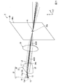
図1、図2および図3は、第1実施形態に係る車両用灯具1の概略を示す図であり、図1は斜視図、図2は側面図、図3は平面図である。本実施形態の車両用灯具1は、車両に搭載され車両の前方(+Z方向)を照射する。
[First Embodiment]
1, FIG. 2 and FIG. 3 are views showing an outline of the
車両用灯具1は、光照射部10と、集光レンズ(第1の光学系)30と、開口41が設けられたカバー部材40と、を備える。また、車両用灯具1は、カバー部材40の前方に図示略のアウターレンズを備えていてもよい。車両用灯具1において、光照射部10から平行光が照射される。平行光は、集光レンズ30により集光され、カバー部材40の開口41を通過して前方に照射される。
The
<光照射部>
光照射部10は、光源本体12を有し光源本体12から照射された光を平行光として集光レンズ30に向けて照射する。光照射部10は、拡散中心11aから放射状に光を照射する光源ユニット11と、光源ユニット11から照射された光を平行光とするコリメートレンズ(第2の光学系)20と、を有する。また、光源ユニット11は、光源本体12と、反射部材14を有する。
<Light irradiation part>
The
光源本体12は、中心軸を上側に向けるランバーシアンな発光光線を照射する。光源本体12から照射されたランバーシアンな発光光線は、反射部材14により前方に向けて反射される。光源本体12としては、発光ダイオード光源(LED、light emitting diode)又はレーザ光源を採用することができる。
The
反射部材14は、光源本体12から照射された光を反射させてコリメートレンズ20に向けて照射する楕円反射面13を有する。すなわち、光源ユニット11は、楕円反射面13を有する。楕円反射面13は、光源本体12を上側から覆う。楕円反射面13は、一対の楕円焦点13a、13bを基準とする楕円形状を、一対の楕円焦点13a、13bを通過する長軸を基準として回転させた楕円球形状を含む。
The reflecting
一対の楕円焦点13a、13bのうち後方に位置する第1の楕円焦点13aには、光源本体12が配置される。楕円の性質により、一方の楕円焦点である第1の楕円焦点13aから照射された光は、楕円反射面13によって反射して他方の楕円焦点である第2の楕円焦点13bに集光する。したがって、光源本体12から照射された光は、第2の楕円焦点13bに集光され、第2の楕円焦点13bを拡散中心11aとしてコリメートレンズ20に向けて放射状に照射される。第2の楕円焦点13bは、光源ユニット11の拡散中心11aとして機能する。
The light source
本実施形態によれば、第1の楕円焦点13aに配置された光源ユニット11は、光源本体12と光源本体12から照射された光を反射させてコリメートレンズ20に向けて照射する楕円反射面13と、を有する。したがって、光源本体12から照射されたランバーシアンな発光光線を第2の楕円焦点13bにおいて狭い拡散角度(狭角)でコリメートレンズ20に入射させることができる。これにより、コリメートレンズ20に効率的に光を入射させることができるとともに、コリメートレンズ20の光軸AX20近傍に高照度領域を形成させるように、光軸AX20近傍の光強度を増大させることができる。また、このようなコリメートレンズ20を採用することで、高照度領域から外側へ行くに従って照度が低下していく照度勾配を持った発光を得ることができる。
According to the present embodiment, the
コリメートレンズ20は、光源ユニット11の拡散中心11aから照射された光を屈折させて平行光とする。コリメートレンズ20は、光源ユニット11の前方に位置する。コリメートレンズ20は、入射面21と出射面25とを有する。入射面は、光源ユニット11に対して前方から対向する。入射面21は、光源ユニット11から照射された光を入射させコリメートレンズ20の内部を通過する一次光L1とする。出射面25は、集光レンズ30と対向する。出射面25は、コリメートレンズ20の内部を進む光(一次光L1)を屈折させて集光レンズ30に向けて二次光L2を出射する。二次光L2は、コリメートレンズ20の光軸AX20と平行な光(すなわち平行光)である。
The collimating
光源ユニット11から出射された光は、入射面21において、コリメートレンズ20の光軸AX20に近づく方向に屈折してコリメートレンズ20の内部を通過する一次光L1となる。図3に示す一次光L1の水平成分の拡散角度は、図2に示す一次光L1の鉛直成分の拡散角度より大きい。すなわち、一次光L1の水平成分と光軸AX20とのなす角は、一次光L1の鉛直成分と光軸AX20のなす角より大きい。
より具体的には、本実施形態において、一次光L1の鉛直成分は、光軸AX20と略平行となっている。すなわち、一次光L1の鉛直成分と光軸AX20とのなす角は、略0°となっている。一方で、一次光L1の水平成分は、前方に向かうに従い光軸AX20から離れる方向に光軸AX20に対して傾いている。すなわち、一次光L1の水平成分は、光軸AX20に対して拡散する。
なお、本明細書において、光の水平成分とは水平面(X−Z平面)と平行な面内における光の進行方向を意味し、光の鉛直成分とは鉛直面(Y−Z平面)と平行な面内における光の進行方向を意味する。
The light emitted from the
More specifically, in the present embodiment, the vertical component of the primary light L1 is substantially parallel to the optical axis AX20. That is, the angle formed by the vertical component of the primary light L1 and the optical axis AX20 is approximately 0 °. On the other hand, the horizontal component of the primary light L1 is tilted with respect to the optical axis AX20 in a direction away from the optical axis AX20 toward the front. That is, the horizontal component of the primary light L1 diffuses with respect to the optical axis AX20.
In the present specification, the horizontal component of light means the traveling direction of light in a plane parallel to the horizontal plane (XX plane), and the vertical component of light is parallel to the vertical plane (YZ plane). It means the direction of travel of light in a horizontal plane.
本実施形態によれば、コリメートレンズ20は、入射面21において入射した光を、鉛直方向に対し水平方向の拡散角度を大きくさせるように屈折させる。これにより、出射面25において平行光として出射される光の配光パターンとして、鉛直方向に対して水平方向を幅広にすることが可能となり、車両用灯具として好ましい配光パターンを形成できる。
According to the present embodiment, the collimating
コリメートレンズ20の入射面21は、水平成分の一部および鉛直成分が双曲線形状を有する。一般的に、双曲線は、それぞれ連続する一対の曲線から構成される。また、これら一対の曲線から構成される双曲線は、一対の焦点を基準として描画される。双曲線の一対の焦点は、それぞれ曲線の内側に配置されている。本明細書における双曲線形状とは、一対の曲線のうち一方の曲線形状を意味する。また、本明細書における双曲線焦点とは、双曲線の基準となる一対の焦点のうち、双曲線形状を構成する曲線に囲まれていない一方の焦点を意味する。双曲線焦点は、入射面21の後方であってコリメートレンズ20の光軸AX20上に位置する。
The
図2に示す様に、入射面21の鉛直成分は、双曲線焦点を光源ユニット11の拡散中心11aに一致させる双曲線形状を有する。コリメートレンズ20の屈折率に合わせて双曲線形状のパラメータを適切に設定することで、双曲線形状の性質により、双曲線焦点から照射された光は、双曲線形状の入射面21において屈折して平行光となる。したがって、本実施形態において、入射面21で屈折された一次光L1の鉛直成分は、光軸AX20と平行とすることができる。これにより、コリメートレンズ20は、前方に照射される配光パターンの鉛直方向の広がりを抑制できる。
なお、一次光L1の鉛直成分は、入射面21において光軸AX20と平行とされているため、出射面25では、屈折させる必要がない。したがって、出射面25の鉛直成分は、光軸AX20と直交する直線状である。
As shown in FIG. 2, the vertical component of the
Since the vertical component of the primary light L1 is parallel to the optical axis AX20 on the
図3に示す様に、入射面21の水平成分は、光軸AX20の近傍において双曲線焦点を拡散中心に一致させる双曲線形状Hを有し、光軸AX20から水平方向外側に離れるに従い双曲線形状Hから後方に離れる形状を有する。上述したように、コリメートレンズ20の屈折率に合わせて双曲線形状のパラメータを適切に設定することで、双曲線形状の性質により、双曲線焦点から照射された光は、光軸AX20の近傍の入射面21において屈折して平行光となる。したがって、本実施形態において、入射面21で屈折された一次光L1の水平成分は、光軸AX20の近傍で光軸AX20と平行とすることができる。これにより、光軸AX20の近傍において、出射面25から出射される光束の密度を高めることができ、水平方向の中央近傍を明るくした配光パターンを実現できる。また、本実施形態によれば、光軸AX20から水平方向外側に離れるに従い、入射面21の水平成分が双曲線形状から後方に離間する。これにより、一次光L1の水平成分は、光軸AX20から水平方向外側に離れることで拡散角度を拡げることができる。したがって、コリメートレンズ20は、光の水平成分の外側の領域を拡散させることで、配光パターンの水平方向の広がりを大きくして、車両用に適した配光パターンを実現できる。
なお、一次光L1の水平成分は、入射面21において光軸AX20に対して傾いた方向に進行し、出射面25において屈折され光軸AX20に対して平行な二次光L2として集光レンズ30に向けて出射される。出射面25の水平成分は、集光レンズ30側に突出する凸形状である。
As shown in FIG. 3, the horizontal component of the
The horizontal component of the primary light L1 travels in a direction inclined with respect to the optical axis AX20 on the
本実施形態によれば、コリメートレンズ20は、入射面21において入射した光を屈折させ、水平方向の拡散角度を、鉛直方向の拡散角度に対して大きくする。これにより、出射面25から平行光として出射される光の配光パターンを、水平方向を幅広にすることが可能となり、車両用灯具1として好ましい配光パターンを形成できる。
According to the present embodiment, the collimating
なお、本明細書において、入射面21の鉛直成分とは、入射面21の鉛直方向に沿う断面形状を意味する。言い換える、入射面21の鉛直成分とは、光軸AX20と平行な鉛直面(Y−Z平面)に対し平行な断面における入射面21の面形状を意味する。同様に、本明細書において、入射面21の水平成分とは、入射面21の水平方向に沿う断面形状を意味する。言い換えると、入射面21の水平成分とは、水平面(X−Z平面)に対し平行な断面における入射面21の面形状を意味する。
In the present specification, the vertical component of the
<集光レンズ(第1の光学系)>
集光レンズ30は、光照射部10の前方に位置する。集光レンズ30は、投影レンズとして機能する。集光レンズ30の光軸AX30は、光照射部10のコリメートレンズ20の光軸AX20と一致する。集光レンズ30は、光照射部10から照射された光を集光する。集光レンズ30は、前方および後方にそれぞれ集光点30a、30bを構成する。ここで一対の集光点30a、30bのうち、集光レンズ30の前方に位置する一方を前方集光点30aとし、後方に位置する他方を後方集光点30bと呼ぶ。光照射部10から照射された平行光としての二次光L2は、集光レンズ30により前方集光点30aに集光される。
なお、本実施形態において、一対の集光点30a、30bは、集光レンズ30の光学的な焦点に一致する。しなしながら、本明細書における集光点とは、集光レンズ30が最も光を集光させることができる点を意味し必ずしも厳密な意味での焦点である必要はない。集光レンズ30は、光を集光させることができれば、厳密な焦点を有さない集光レンズであってもよく、その場合、最も光が集光する点が集光点と定義される。
<Condensing lens (first optical system)>
The
In this embodiment, the pair of condensing
図4は、本実施形態の車両用灯具1の模式図である。集光レンズ30の光軸AX30に対し光軸AX30と直交する方向へ距離yだけ離れた地点を通って集光レンズ30に入射する光Laは、集光レンズ30の実効焦点距離をFとした時に、集光レンズ30の焦点(集光点30a)に、光軸AX30に対する角度θ=tan−1(y/F)で入射し、その後、車両前方へ投影される。なお、実効焦点距離Fは、集光レンズ30の入出射前後の光路の延長線のレンズ内における交点CPから焦点(集光点30a、30b)までの距離である。上述の式に従い、コリメートレンズ20により平行光として形成した車両に適した面分布の配光パターンは、所定の角度を有する光に変換され車両前方に投影される。
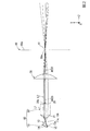
FIG. 4 is a schematic diagram of the
本実施形態において、集光レンズ30は、後方面が平面かつ前方面が凸面の凸レンズである。しかしながら、集光レンズ30は、前方の集光点30aに光を集光させる第1の光学系の一例であり、その構成は本実施形態に限定されない。例えば、第1の光学系として、集光レンズ30に代えて、複数の光学系を、それぞれの光軸同士を一致させて前後方向に並べた構成としてもよい。なお、図4は、模式化された図であり、集光レンズ30の前方面および後方面が凸面であるものとして図示されている。このように、集光レンズ30は、前方面および後方面が凸面であってもよい。
In the present embodiment, the
<カバー部材>
カバー部材40は、板形状を有する。カバー部材40は、集光レンズ30の前方に位置する。カバー部材40は、前方から見て集光レンズ30の少なくとも一部と重なる。すなわち、カバー部材40は、集光レンズ30を前方から覆う。カバー部材40の前方面40aは、意匠面として機能する。すなわち、カバー部材40の前方面40aは、前方から見て集光レンズ30および光照射部10を含む内部構造を見えづらくする。これにより、カバー部材40は、車両用灯具1の意匠性を高める。
<Cover member>
The
カバー部材40には、前後方向に貫通する開口41が設けられている。本実施形態において開口41は、ピンホールである。開口41は、例えば一方向に延びるスリットであってもよい。また、開口41の形状は、前方に照射する配光パターンの形状に合わせて水平方向に幅広な形状としてもよい。
The
開口41は、集光レンズ30の光軸AX30上に位置する。光照射部10から照射された平行光(二次光L2)は、集光レンズ30で屈折され集光レンズ30の光軸AX30上において集光される。したがって、開口41を集光レンズ30の光軸AX30上に配置することで、通過する範囲を狭めた光を開口41に通過させることができる。すなわち、開口41を集光レンズ30の光軸AX30上に配置することで、開口41を小さくして車両用灯具1の内部構造を見えづらくすることができる。
The
また、本実施形態において、開口41は、集光レンズ30の前方集光点30aに位置する。集光レンズ30によって屈折された光は、前方集光点30aにおいて最も集光する。開口41を前方集光点30aに配置することで、開口41を最も小さくすることができ、結果として、カバー部材40が、車両用灯具1の内部構造を見えづらくする効果を高めることができる。
Further, in the present embodiment, the
本実施形態によれば、集光レンズ30の前方に集光レンズ30の少なくとも一部と重なるカバー部材40が設けられている。このため、内部構造が前方から遮蔽され、意匠性を高めた車両用灯具1を実現できる。また、カバー部材40には、集光レンズ30の光軸AX30上に位置する開口41が設けられている。集光レンズ30は、光照射部10により平行とされた光が入光して、光軸AX30上に集光させて開口41を通過させる。したがって、前方を照射する光は、カバー部材40によって遮蔽されることがない。
According to the present embodiment, a
また、本実施形態によれば、カバー部材40の前方面40aを意匠面として機能するため、集光レンズ30の大きさに制約されずに意匠面の大きさを決めることができる。したがって、外見上コンパクトに見せて意匠性を高めた車両用灯具1を提供できる。
Further, according to the present embodiment, since the
また、本実施形態によれば、コリメートレンズ20の入射面21および出射面25を適切に設計することで、光照射部10が照射する平行光(二次光L2)に照度勾配を持った分布を生成する。これにより、車両用灯具1は、高照度領域から外側へ行くに従って照度が低下していく配光パターンを形成できる(図5および図6参照)。
Further, according to the present embodiment, by appropriately designing the
なお、本実施形態において、光照射部10として、集光レンズ30に平行光を入射させる構成を採用する場合について説明した。しかしながら、集光レンズ30によって前方に光を集光させることができれば、光照射部10は、必ずしも平行光を照射するものでなくてもよい。なお、光照射部10が平行光を照射する場合は、単純な面形状の集光レンズ30によって光を明瞭に集光させることができ、より好ましい。
In the present embodiment, the case where the
[第2実施形態]
次に、図4を基に第2実施形態の車両用灯具101について説明する。第2実施形態の車両用灯具101は、上述の実施形態と比較して画像光形成装置150を備える点が主に異なる。なお、上述の実施形態と同一態様の構成要素については、同一符号を付し、その説明を省略する。
[Second Embodiment]
Next, the
車両用灯具101は、光照射部10、集光レンズ(第1の光学系)30およびカバー部材40に加えて画像光を形成する画像光形成装置150を備える。画像光形成装置150は、光を変調して画像光を形成する。本実施形態において画像光形成装置150は、光を透過させる際に画像光を形成する透過型の液晶パネルである。しかしながら、画像光形成装置150は、反射型の液晶パネルであってもよく、回動可能な複数の微小ミラーをアレイ(マトリックス)状に配列され光を反射させる際に画像光を形成するDMD(Digital Mirror Device)であってもよい。画像光形成装置150を光源本体12から集光レンズ30までの経路中に配置することで、集光光学系に入射する光を画像光とすることができ、前方に照射する配光パターンを経時的に変化させることができる。すなわちこの構成によれば、車両用灯具は、ADB(Adaptive Driving Beam)制御を行うことができる。
以下、本実施形態の説明において、画像生成装置を液晶パネル150と呼ぶ。
The
Hereinafter, in the description of this embodiment, the image generation device will be referred to as a
液晶パネル150は、光照射部10と集光レンズ30との間に位置する。すなわち、液晶パネル150には、光照射部10により平行光とされた光の一部を透過させ、また他の一部を遮蔽して画像光を形成する。液晶パネル150を光照射部10と集光レンズ30との間に配置することで、液晶パネル150を透過する光を平行光とすることができるため、より鮮明な画像光を形成できる。すなわち本実施形態によれば、光照射部10から照射された平行光を利用して液晶パネル150によって画像光を形成することで、より鮮明な配光パターンを形成できる。
The
また、液晶パネル150として、透過する光を拡散させる液晶パネルを用いる場合がある。拡散された光は、集光レンズ30により前方集光点30aに集光されることがない。したがって、拡散された光は、カバー部材40の開口41を通過され難く、前方に照射される配光パターンを鮮明とすることができる。
Further, as the
液晶パネル150は、集光レンズ30の後方集光点30bにおいて集光レンズ30の光軸AX30と直交して配置されている。車両用灯具101は、集光レンズ30の後方集光点30bを通過する画像光を前方に配光パターンとして投影する。一方で、光照射部10において、完全に平行な光のみを形成することは困難であるため、光照射部10から照射される光には、一部に非平行な光を含む。液晶パネルが集光レンズの後方集光点に位置しない場合には、光照射部10から照射された非平行な光が後方の焦点(後方集光点30b)を通過し、画像光を不鮮明にして、結果として前方の配光パターンを不鮮明とする場合がある。本実施形態によれば、液晶パネル150が集光レンズ30の後方集光点30bにおいて集光レンズ30の光軸AX30と直交して配置されるため、非平行な光であっても後方集光点30bを通過し光軸AX30と直交する面内で液晶パネル150を透過する。したがって、本実施形態の車両用灯具101によれば、より鮮明な配光パターンを形成することができる。
The
一般的に、液晶パネルに用いられる液晶素子は、光の入射角度によって透過性能が変わることが知られている。すなわち、液晶素子は、特定の角度(例えば液晶パネルと直交する方向)からの光に対して最もコントラスト(明暗透過率比)が高くなるが、特定角度からずれるに従ってコントラストが低下するという特性を有している。このため、液晶素子に入射する光が角度分布を持っていると、特定角度から最もずれた光が入射する領域のコントラストの低下に合わせて画像光全体の明暗透過率比も下がってしまう。
本実施形態によれば、液晶パネル150を平行光と直交して配置することにより、液晶パネル150の最もコントラストが高くなる入射角度の光のみを利用でき、画像光の明暗透過率比を高めることができる。すなわち本実施形態によれば、明瞭な配光パターンを形成する車両用灯具101を提供できる。
このように、液晶パネル150は、平行光を入射する場合に高い性能を発揮する。したがって、本実施形態の車両用灯具101は、画像光形成装置として液晶パネル150を用いた場合に最も効果を奏するものである。
Generally, it is known that the transmission performance of a liquid crystal element used in a liquid crystal panel changes depending on the incident angle of light. That is, the liquid crystal element has the characteristic that the contrast (bright-dark transmittance ratio) is the highest with respect to the light from a specific angle (for example, the direction orthogonal to the liquid crystal panel), but the contrast decreases as the angle deviates from the specific angle. doing. Therefore, if the light incident on the liquid crystal element has an angular distribution, the light-dark transmittance ratio of the entire image light also decreases as the contrast of the region in which the light most deviated from the specific angle is incident decreases.
According to the present embodiment, by arranging the
As described above, the
本実施形態によれば、液晶パネル150を設けた上述の効果に加えて、第1の実施形態と同様の効果を奏することができる。
According to the present embodiment, in addition to the above-mentioned effect provided with the
以下、実施例により本発明の効果をより明らかなものとする。なお、本発明は、以下の実施例に限定されるものではなく、その要旨を変更しない範囲で適宜変更して実施することができる。 Hereinafter, the effects of the present invention will be further clarified by examples. The present invention is not limited to the following examples, and can be appropriately modified and implemented without changing the gist thereof.
[第1実施形態に対応する配光パターン]
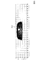
図5は、上述した第1実施形態の車両用灯具1において、車両用灯具1に正対した仮想鉛直スクリーンに対する配光パターンP1のシミュレーション結果を示す。なお、このシミュレーションにおいて、集光レンズ30の有効レンズ高さが30mmであり、カバー部材40の鉛直方向の寸法が10mmである。
[Light distribution pattern corresponding to the first embodiment]
FIG. 5 shows the simulation result of the light distribution pattern P1 for the virtual vertical screen facing the
図5に示す様に、配光パターンP1は、中心に高照度帯が設けられると共に鉛直方向に対して水平方向が幅広であり、車両用灯具の配光パターンとして好ましい形状に構成されている。また、配光パターンP1の全光束を確認すると、アウターレンズ(図1〜図3において省略)における光の損失を考慮した場合であっても、光の利用効率を50%以上とされている。したがって、第1実施形態の車両用灯具1によれば、高効率かつ意匠性が高く好ましい配光パターンP1を形成できる。なお、光の利用効率とは、光源本体から照射される全光束に対する前方に照射される光束の比を百分率で表した指標である。
As shown in FIG. 5, the light distribution pattern P1 is provided with a high illuminance band in the center and is wide in the horizontal direction with respect to the vertical direction, and is configured in a preferable shape as a light distribution pattern for vehicle lighting equipment. Further, when the total luminous flux of the light distribution pattern P1 is confirmed, the light utilization efficiency is set to 50% or more even when the light loss in the outer lens (omitted in FIGS. 1 to 3) is taken into consideration. Therefore, according to the
[第2実施形態に対応する配光パターン]
図6は、上述した第2実施形態の車両用灯具101において、車両用灯具101に正対した仮想鉛直スクリーンに対する配光パターンP101のシミュレーション結果を示す。なお、このシミュレーションにおいて、液晶パネル150は、透過させる光の一部(配光パターンP101において中心右上の領域)を遮光する。
[Light distribution pattern corresponding to the second embodiment]
FIG. 6 shows the simulation result of the light distribution pattern P101 for the virtual vertical screen facing the
図5に示す様に、第2実施形態に対応する配光パターンP101は、第1実施形態に対応する配光パターンP1と同様の効果を奏するとともに、部分的に光を照射しない領域を形成できる。すなわち、第2実施形態に対応する配光パターンP101によれば、部分的に光の照射をマスクするADB制御を鮮明に行うことができる。 As shown in FIG. 5, the light distribution pattern P101 corresponding to the second embodiment has the same effect as the light distribution pattern P1 corresponding to the first embodiment, and can form a region partially not irradiated with light. .. That is, according to the light distribution pattern P101 corresponding to the second embodiment, ADB control that partially masks the irradiation of light can be clearly performed.
以上に、本発明の様々な実施形態を説明したが、各実施形態における各構成およびそれらの組み合わせ等は一例であり、本発明の趣旨から逸脱しない範囲内で、構成の付加、省略、置換およびその他の変更が可能である。また、本発明は実施形態によって限定されない。 Although various embodiments of the present invention have been described above, the configurations and combinations thereof in each embodiment are examples, and additions, omissions, substitutions, and configurations of the configurations are added, omitted, and substituted without departing from the spirit of the present invention. Other changes are possible. Further, the present invention is not limited to the embodiments.
1,101…車両用灯具、10…光照射部、11…光源ユニット、11a…拡散中心、12…光源本体、13…楕円反射面、13a、13b…楕円焦点、20…コリメートレンズ(第2の光学系)、21…入射面、25…出射面、30a…前方集光点(集光点)、30b…集光点焦点(集光点)、40…カバー部材、41…開口、150…画像光形成装置(液晶パネル)、AX20,AX30…光軸、L1…一次光、L2…二次光 1,101 ... Vehicle optics, 10 ... Light irradiation unit, 11 ... Light source unit, 11a ... Diffusion center, 12 ... Light source body, 13 ... Elliptical reflection surface, 13a, 13b ... Elliptical focus, 20 ... Collimating lens (second) Optical system), 21 ... Incident surface, 25 ... Emission surface, 30a ... Front light source point (light source point), 30b ... Light source point focus (light source point), 40 ... Cover member, 41 ... Opening, 150 ... Image Light forming device (liquid crystal panel), AX20, AX30 ... Optical axis, L1 ... Primary light, L2 ... Secondary light
Claims (8)
光源本体を有する光照射部と、
前記光照射部から照射された光を集光する第1の光学系と、
前記第1の光学系の前方に位置し前方から見て前記第1の光学系の少なくとも一部と重なるカバー部材と、を備え、
前記カバー部材には、前記第1の光学系の光軸上に位置する開口が設けられており、
前記光照射部は、前記光源本体から照射された光を平行光として照射し、
前記光照射部は、前記光源本体を有し拡散中心から放射状に光を照射する光源ユニットと、前記光源ユニットから照射された光を前記平行光とする第2の光学系と、を有し、
前記第2の光学系は、前記光源ユニットから照射された光を入射させ前記第2の光学系の内部を通過する一次光とする入射面と、前記第2の光学系の光軸と平行な二次光を出射する出射面と、を有し、
前記一次光の水平成分の拡散角度が、前記一次光の鉛直方向の成分の拡散角度より大きく、
前記入射面の水平成分は、前記第2の光学系の光軸の近傍において双曲線焦点を前記拡散中心に一致させる双曲線形状を有し、前記第2の光学系の光軸から水平方向外側に離れるに従い双曲線形状から後方に離れる形状を有する、
車両用灯具。 A vehicle lamp that illuminates the front of the vehicle.
A light irradiation unit having a light source body and
A first optical system that collects the light emitted from the light irradiation unit, and
A cover member located in front of the first optical system and overlapping with at least a part of the first optical system when viewed from the front is provided.
The cover member is provided with an opening located on the optical axis of the first optical system .
The light irradiation unit irradiates the light emitted from the light source main body as parallel light.
The light irradiation unit includes a light source unit having the light source main body and radiating light from the diffusion center, and a second optical system in which the light emitted from the light source unit is the parallel light.
The second optical system is parallel to the incident surface, which is the primary light that incidents the light emitted from the light source unit and passes through the inside of the second optical system, and the optical axis of the second optical system. It has an exit surface that emits secondary light,
The diffusion angle of the horizontal component of the primary light is larger than the diffusion angle of the vertical component of the primary light.
The horizontal component of the incident surface has a hyperbolic shape that makes the hyperbolic focus coincide with the diffusion center in the vicinity of the optical axis of the second optical system, and is separated from the optical axis of the second optical system in the horizontal direction. It has a shape that moves backward from the hyperbolic shape according to
Vehicle lighting equipment.
請求項1に記載の車両用灯具。 The aperture is located at a condensing point in front of the first optical system.
The vehicle lighting fixture according to claim 1.
請求項1又は2に記載の車両用灯具。 The parallel light has a distribution having an illuminance gradient.
The vehicle lamp according to claim 1 or 2.
請求項1〜3の何れか一項に記載の車両用灯具。 The vertical component of the incident surface has a hyperbolic shape that aligns the hyperbolic focus with the diffusion center.
The vehicle lamp according to any one of claims 1 to 3.
前記楕円反射面は、一対の楕円焦点を基準とする楕円形状に構成され、
一対の前記楕円焦点のうち、一方には前記光源本体が配置され、他方が前記拡散中心として機能する、
請求項1〜4の何れか一項に記載の車両用灯具。 The light source unit has a light source main body and an elliptical reflective surface that reflects light emitted from the light source main body and irradiates the second optical system toward the second optical system.
The elliptical reflection surface is configured in an elliptical shape with respect to a pair of elliptical focal points.
Of the pair of elliptical focal points, one is arranged with the light source body and the other functions as the diffusion center.
The vehicle lamp according to any one of claims 1 to 4.
請求項1〜5の何れか一項に記載の車両用灯具。 An image light forming apparatus is provided, which is arranged in a light path from the light source main body to the first optical system and modulates the light to form an image light.
The vehicle lamp according to any one of claims 1 to 5.
前記液晶パネルは、前記光照射部と前記第1の光学系との間に位置する、
請求項6に記載の車両用灯具。 The image light forming apparatus is a liquid crystal panel.
The liquid crystal panel is located between the light irradiation unit and the first optical system.
The vehicle lamp according to claim 6.
請求項7に記載の車両用灯具。 The liquid crystal panel is arranged orthogonal to the optical axis of the first optical system at a condensing point behind the first optical system.
The vehicle lamp according to claim 7.
Priority Applications (3)
| Application Number | Priority Date | Filing Date | Title |
|---|---|---|---|
| JP2017102638A JP6975552B2 (en) | 2017-05-24 | 2017-05-24 | Vehicle lighting |
| US16/613,704 US10941917B2 (en) | 2017-05-24 | 2018-05-18 | Lighting tool for vehicle |
| PCT/JP2018/019331 WO2018216622A1 (en) | 2017-05-24 | 2018-05-18 | Vehicle lamp |
Applications Claiming Priority (1)
| Application Number | Priority Date | Filing Date | Title |
|---|---|---|---|
| JP2017102638A JP6975552B2 (en) | 2017-05-24 | 2017-05-24 | Vehicle lighting |
Publications (2)
| Publication Number | Publication Date |
|---|---|
| JP2018198164A JP2018198164A (en) | 2018-12-13 |
| JP6975552B2 true JP6975552B2 (en) | 2021-12-01 |
Family
ID=64395635
Family Applications (1)
| Application Number | Title | Priority Date | Filing Date |
|---|---|---|---|
| JP2017102638A Active JP6975552B2 (en) | 2017-05-24 | 2017-05-24 | Vehicle lighting |
Country Status (3)
| Country | Link |
|---|---|
| US (1) | US10941917B2 (en) |
| JP (1) | JP6975552B2 (en) |
| WO (1) | WO2018216622A1 (en) |
Families Citing this family (2)
| Publication number | Priority date | Publication date | Assignee | Title |
|---|---|---|---|---|
| KR102490584B1 (en) * | 2020-11-19 | 2023-01-19 | 주식회사 엠에스엘테크놀로지 | Lamp unit for landing induction of helicopter at night |
| CN217785016U (en) * | 2022-04-29 | 2022-11-11 | 北京车和家汽车科技有限公司 | Reflector, projection assembly, lamp and vehicle |
Family Cites Families (11)
| Publication number | Priority date | Publication date | Assignee | Title |
|---|---|---|---|---|
| JP4387783B2 (en) * | 2003-12-17 | 2009-12-24 | 株式会社小糸製作所 | Projector type headlight |
| AT507530B1 (en) * | 2008-11-04 | 2013-05-15 | Al Systems Gmbh | LIGHTING ELEMENT FOR A LIGHTING DEVICE AND LIGHTING DEVICE |
| JP2010262750A (en) * | 2009-04-30 | 2010-11-18 | Koito Mfg Co Ltd | Vehicle lighting |
| JP5448615B2 (en) * | 2009-07-14 | 2014-03-19 | 株式会社小糸製作所 | Vehicle headlamp |
| JP2013101881A (en) | 2011-11-09 | 2013-05-23 | Stanley Electric Co Ltd | Vehicle headlamp |
| JP5812283B2 (en) | 2011-12-20 | 2015-11-11 | スタンレー電気株式会社 | LIGHT EMITTING DEVICE, VEHICLE LIGHT, AND VEHICLE |
| DE102012024625A1 (en) * | 2012-12-17 | 2014-06-18 | GM Global Technology Operations LLC (n. d. Gesetzen des Staates Delaware) | Lamp arrangement for headlight module of motor vehicle e.g. motor car, has light source having light exit openings that are spaced apart from each other in propagation direction of light beam and are arranged in panel form |
| JP6654560B2 (en) * | 2014-05-07 | 2020-02-26 | 株式会社小糸製作所 | Light source module and vehicle lamp |
| EP3179158A4 (en) * | 2014-08-07 | 2018-03-21 | Koito Manufacturing Co., Ltd. | Lamp for vehicles |
| EP3434966B1 (en) * | 2016-03-24 | 2023-02-22 | Koito Manufacturing Co., Ltd. | Vehicle lamp and vehicle provided with it |
| US10180222B2 (en) * | 2016-10-14 | 2019-01-15 | Koito Manufacturing Co., Ltd. | Optical unit |
-
2017
- 2017-05-24 JP JP2017102638A patent/JP6975552B2/en active Active
-
2018
- 2018-05-18 WO PCT/JP2018/019331 patent/WO2018216622A1/en not_active Ceased
- 2018-05-18 US US16/613,704 patent/US10941917B2/en active Active
Also Published As
| Publication number | Publication date |
|---|---|
| JP2018198164A (en) | 2018-12-13 |
| US10941917B2 (en) | 2021-03-09 |
| US20200292145A1 (en) | 2020-09-17 |
| WO2018216622A1 (en) | 2018-11-29 |
Similar Documents
| Publication | Publication Date | Title |
|---|---|---|
| KR102841260B1 (en) | Luminous device imaging the lit surfaces of at least two collectors | |
| JP6506885B2 (en) | Lighting device of light projector for motor vehicle | |
| JP7002255B2 (en) | Vehicle lighting | |
| CN112443806B (en) | headlamp module | |
| JP5881887B2 (en) | Projection module for automobile | |
| CN107960117B (en) | Headlamp module and headlamp device | |
| WO2018043663A1 (en) | Vehicular lamp | |
| JP2017212037A (en) | Vehicle headlamp | |
| CN113892043B (en) | Light guide for vehicle and lamp unit for vehicle | |
| JP2010080306A (en) | Lighting fixture unit for vehicular headlight | |
| JP6862291B2 (en) | Vehicle lighting | |
| CN114623414B (en) | Lamp for vehicle | |
| JP2012209083A (en) | Vehicular lamp | |
| JP6975553B2 (en) | Collimating lenses, light illuminators and vehicle lamps. | |
| JP5445049B2 (en) | Vehicle lighting | |
| JP6975552B2 (en) | Vehicle lighting | |
| JP5446757B2 (en) | Vehicle lighting | |
| JP6331797B2 (en) | In-vehicle light source device | |
| JP7495932B2 (en) | Vehicle lighting fixtures | |
| JP5397174B2 (en) | Vehicle lighting | |
| WO2021200721A1 (en) | Vehicle light guide body and vehicle lighting unit | |
| JP2016134200A (en) | Vehicle lighting | |
| JP2013033622A (en) | Lamp fitting |
Legal Events
| Date | Code | Title | Description |
|---|---|---|---|
| A621 | Written request for application examination |
Free format text: JAPANESE INTERMEDIATE CODE: A621 Effective date: 20200415 |
|
| A131 | Notification of reasons for refusal |
Free format text: JAPANESE INTERMEDIATE CODE: A131 Effective date: 20210420 |
|
| A521 | Request for written amendment filed |
Free format text: JAPANESE INTERMEDIATE CODE: A523 Effective date: 20210614 |
|
| TRDD | Decision of grant or rejection written | ||
| A01 | Written decision to grant a patent or to grant a registration (utility model) |
Free format text: JAPANESE INTERMEDIATE CODE: A01 Effective date: 20211019 |
|
| A61 | First payment of annual fees (during grant procedure) |
Free format text: JAPANESE INTERMEDIATE CODE: A61 Effective date: 20211108 |
|
| R150 | Certificate of patent or registration of utility model |
Ref document number: 6975552 Country of ref document: JP Free format text: JAPANESE INTERMEDIATE CODE: R150 |
|
| R250 | Receipt of annual fees |
Free format text: JAPANESE INTERMEDIATE CODE: R250 |
|
| R250 | Receipt of annual fees |
Free format text: JAPANESE INTERMEDIATE CODE: R250 |