JP6973845B2 - Electrostatic particle sensor - Google Patents
Electrostatic particle sensor Download PDFInfo
- Publication number
- JP6973845B2 JP6973845B2 JP2017008017A JP2017008017A JP6973845B2 JP 6973845 B2 JP6973845 B2 JP 6973845B2 JP 2017008017 A JP2017008017 A JP 2017008017A JP 2017008017 A JP2017008017 A JP 2017008017A JP 6973845 B2 JP6973845 B2 JP 6973845B2
- Authority
- JP
- Japan
- Prior art keywords
- sensor
- outer housing
- sensor assembly
- amplifier
- electrostatic
- Prior art date
- Legal status (The legal status is an assumption and is not a legal conclusion. Google has not performed a legal analysis and makes no representation as to the accuracy of the status listed.)
- Active
Links
- 239000002245 particle Substances 0.000 title claims description 55
- 238000001514 detection method Methods 0.000 claims description 51
- 239000000428 dust Substances 0.000 claims description 14
- 239000000446 fuel Substances 0.000 claims description 13
- 239000012212 insulator Substances 0.000 claims description 12
- 230000027756 respiratory electron transport chain Effects 0.000 claims description 10
- 239000012530 fluid Substances 0.000 claims description 9
- XLYOFNOQVPJJNP-UHFFFAOYSA-N water Substances O XLYOFNOQVPJJNP-UHFFFAOYSA-N 0.000 claims description 4
- 239000003570 air Substances 0.000 claims description 3
- 239000003921 oil Substances 0.000 claims description 3
- 239000004576 sand Substances 0.000 claims description 3
- 229910052710 silicon Inorganic materials 0.000 claims description 2
- 239000010703 silicon Substances 0.000 claims description 2
- 239000007789 gas Substances 0.000 description 27
- 238000000034 method Methods 0.000 description 19
- 238000002485 combustion reaction Methods 0.000 description 14
- 230000006870 function Effects 0.000 description 9
- 230000035945 sensitivity Effects 0.000 description 7
- 238000004891 communication Methods 0.000 description 6
- 238000010586 diagram Methods 0.000 description 6
- 230000008901 benefit Effects 0.000 description 4
- 239000000919 ceramic Substances 0.000 description 4
- 239000004020 conductor Substances 0.000 description 4
- 238000004887 air purification Methods 0.000 description 3
- 239000003990 capacitor Substances 0.000 description 3
- 238000009434 installation Methods 0.000 description 3
- 238000012423 maintenance Methods 0.000 description 3
- 239000002184 metal Substances 0.000 description 3
- 229910052751 metal Inorganic materials 0.000 description 3
- 230000004044 response Effects 0.000 description 3
- 239000000758 substrate Substances 0.000 description 3
- 238000011144 upstream manufacturing Methods 0.000 description 3
- RYGMFSIKBFXOCR-UHFFFAOYSA-N Copper Chemical compound [Cu] RYGMFSIKBFXOCR-UHFFFAOYSA-N 0.000 description 2
- 230000004888 barrier function Effects 0.000 description 2
- 239000000567 combustion gas Substances 0.000 description 2
- 229910052802 copper Inorganic materials 0.000 description 2
- 239000010949 copper Substances 0.000 description 2
- 230000008878 coupling Effects 0.000 description 2
- 238000010168 coupling process Methods 0.000 description 2
- 238000005859 coupling reaction Methods 0.000 description 2
- 239000013078 crystal Substances 0.000 description 2
- 238000013461 design Methods 0.000 description 2
- 239000010419 fine particle Substances 0.000 description 2
- 239000000203 mixture Substances 0.000 description 2
- 229910001120 nichrome Inorganic materials 0.000 description 2
- 230000008569 process Effects 0.000 description 2
- 230000008646 thermal stress Effects 0.000 description 2
- 101001128814 Pandinus imperator Pandinin-1 Proteins 0.000 description 1
- 101001024685 Pandinus imperator Pandinin-2 Proteins 0.000 description 1
- 238000009825 accumulation Methods 0.000 description 1
- PNEYBMLMFCGWSK-UHFFFAOYSA-N aluminium oxide Inorganic materials [O-2].[O-2].[O-2].[Al+3].[Al+3] PNEYBMLMFCGWSK-UHFFFAOYSA-N 0.000 description 1
- 238000013459 approach Methods 0.000 description 1
- 238000005336 cracking Methods 0.000 description 1
- 230000006866 deterioration Effects 0.000 description 1
- 230000000694 effects Effects 0.000 description 1
- 230000007613 environmental effect Effects 0.000 description 1
- 229920006334 epoxy coating Polymers 0.000 description 1
- 239000011888 foil Substances 0.000 description 1
- 239000002737 fuel gas Substances 0.000 description 1
- 239000007788 liquid Substances 0.000 description 1
- 230000007935 neutral effect Effects 0.000 description 1
- 239000013618 particulate matter Substances 0.000 description 1
- 238000010248 power generation Methods 0.000 description 1
- 239000004065 semiconductor Substances 0.000 description 1
Images


Classifications
-
- G—PHYSICS
- G01—MEASURING; TESTING
- G01N—INVESTIGATING OR ANALYSING MATERIALS BY DETERMINING THEIR CHEMICAL OR PHYSICAL PROPERTIES
- G01N15/00—Investigating characteristics of particles; Investigating permeability, pore-volume, or surface-area of porous materials
- G01N15/06—Investigating concentration of particle suspensions
- G01N15/0656—Investigating concentration of particle suspensions using electric, e.g. electrostatic methods or magnetic methods
-
- G—PHYSICS
- G01—MEASURING; TESTING
- G01N—INVESTIGATING OR ANALYSING MATERIALS BY DETERMINING THEIR CHEMICAL OR PHYSICAL PROPERTIES
- G01N15/00—Investigating characteristics of particles; Investigating permeability, pore-volume, or surface-area of porous materials
- G01N15/02—Investigating particle size or size distribution
- G01N15/0266—Investigating particle size or size distribution with electrical classification
-
- G—PHYSICS
- G01—MEASURING; TESTING
- G01N—INVESTIGATING OR ANALYSING MATERIALS BY DETERMINING THEIR CHEMICAL OR PHYSICAL PROPERTIES
- G01N15/00—Investigating characteristics of particles; Investigating permeability, pore-volume, or surface-area of porous materials
- G01N2015/0042—Investigating dispersion of solids
- G01N2015/0046—Investigating dispersion of solids in gas, e.g. smoke
-
- G—PHYSICS
- G01—MEASURING; TESTING
- G01N—INVESTIGATING OR ANALYSING MATERIALS BY DETERMINING THEIR CHEMICAL OR PHYSICAL PROPERTIES
- G01N2291/00—Indexing codes associated with group G01N29/00
- G01N2291/02—Indexing codes associated with the analysed material
- G01N2291/024—Mixtures
- G01N2291/02416—Solids in liquids
Description
本主題は、一般に粒子センサに関し、より具体的には、静電気ダストセンサに関する。 The subject generally relates to particle sensors, and more specifically to electrostatic dust sensors.
多くの型式のエンジンは、最大限のエンジン性能及びエンジン寿命を保証するため及び保守の必要性を減らすために大量の清浄空気の供給を必要とする場合が多い。空気吸入システムに引き込まれた粒子状物質の99%を除去する空気清浄システムが幾つかの型式のエンジン用に開発されている。このような高効率の空気清浄システムは、障壁型空気フィルタを含む多段ユニットである。しかしながら、空気清浄システム内で単にダストが漏れる(例えば空気フィルタの1つに偶発的に穴が空くことによって生じる)だけで、システムの効力が無効になってしまうことがある。加えて、障壁フィルタを使用することができないガスタービンエンジン等の他の型式の用途では、過度にダストが多い空気に伴う問題に直面することがある。 Many types of engines often require a large supply of clean air to ensure maximum engine performance and engine life and to reduce the need for maintenance. Air purification systems have been developed for several types of engines that remove 99% of the particulate matter drawn into the air intake system. Such a highly efficient air purification system is a multi-stage unit including a barrier type air filter. However, simply leaking dust within an air purification system (eg, accidentally punctured in one of the air filters) can invalidate the system. In addition, other types of applications, such as gas turbine engines where barrier filters cannot be used, may face the problems associated with excessively dusty air.
典型的なガスタービンエンジンは、一般に直列流れ順に、圧縮機セクション、燃焼器セクション、タービンセクション及び排出セクションを含む。動作時、空気は、圧縮機セクションに入り、そこで1又は2以上の軸流又は遠心圧縮機が空気を燃焼セクションに達するまで徐々に圧縮する。燃焼セクション内で圧縮空気に燃料が混合されて燃焼し、燃焼ガスがもたらされる。燃焼ガスは、燃焼セクションからタービンセクション内に定められた熱ガス路を通って送られ、次いでタービンセクションから排出セクションを介して排出される。 A typical gas turbine engine generally includes a compressor section, a combustor section, a turbine section and an exhaust section in series flow order. During operation, the air enters the compressor section, where one or more axial or centrifugal compressors gradually compress the air until it reaches the combustion section. Fuel is mixed with compressed air in the combustion section and burned, resulting in combustion gas. Combustion gas is sent from the combustion section through a hot gas path defined within the turbine section and then discharged from the turbine section through the exhaust section.
このようなガスタービンエンジンは、通常、航空機に使用される。航空機の運航中、エンジン環境の微粒子及びダストの吸い込みレベルは、解析プロセスへの主要な入力であり、その結果、特定のエンジン毎のアクションが得られる。最新の環境のダスト/微粒子レベルデータは、航空機とは別個の地上の遠隔検出システムによって提供される。かかるデータは一時的及び特別な変動並びに誤差を有するので、航空機の離陸時及び上昇時のエンジン状態の正確な評価は特に困難である。他方、センサがエンジンに取り付けられた場合、かかるセンサシステムの電子機器は、典型的には複数の長いケーブル及びコネクタを介して個別のセンサに接続されることになる。この場合、ケーブル布線の何らかの移動又は振動によって、センサ面を通過するダスト粒子よりも大きい信号が生成される場合があり、それにより信号対雑音比が不良になりかねない。これらのスプリアス信号は、ケーブル及びコネクタの摩擦電気及び圧電効果に起因する。 Such gas turbine engines are typically used in aircraft. During the operation of the aircraft, the level of fine particle and dust suction in the engine environment is a major input to the analysis process, resulting in specific engine-specific actions. Up-to-date environmental dust / particle level data is provided by a remote detection system on the ground separate from the aircraft. Accurate assessment of engine condition during takeoff and ascent of an aircraft is particularly difficult because such data have temporary and special fluctuations and errors. On the other hand, when the sensor is attached to the engine, the electronics of such a sensor system will typically be connected to a separate sensor via a plurality of long cables and connectors. In this case, any movement or vibration of the cable wiring may generate a signal larger than the dust particles passing through the sensor surface, which may result in a poor signal-to-noise ratio. These spurious signals are due to the triboelectric and piezoelectric effects of cables and connectors.
従って、本開示は、上記問題に対処する改善されたセンサシステムに向けられる。より詳細には、本開示は、ダスト粒子及び/又は微粒子をより正確に検出する、統合型電子機器及び/又はより短いケーブル接続を有する1又は2以上の改善された静電気センサを含むセンサ組立体に向けられる。 Therefore, the present disclosure is directed to an improved sensor system that addresses the above problems. More specifically, the present disclosure comprises a sensor assembly comprising an integrated electronic device and / or one or more improved electrostatic sensors with shorter cable connections that more accurately detect dust particles and / or fine particles. Directed to.
本発明の態様及び利点は、その一部を以下の説明に記載しており、又はこの説明から明らかにすることができ、或いは本発明を実施することにより理解することができる。 Aspects and advantages of the present invention are described in part in the following description, or can be clarified from this description, or can be understood by practicing the present invention.
1つの態様において、本開示は、回路基板に電気的に結合された少なくとも1つの静電気センサを有する統合型センサ組立体に向けられる。静電気センサは、電極及び増幅器を内部に収容した外側ハウジングを含む。電極は、所定の長さで隔てられた第1の端部と第2の端部とを含む。第2の端部は、外側ハウジングの縁と実質的に面一の検知面を含む。電極は導体であり、検知面を通過する1又は2以上の荷電粒子に対して、第2の端部に向かう方向又は遠ざかる方向のいずれかに移動することによって応答するようになった複数の電子を包含する。従って、増幅器は、電極に電気的に結合され、検知面を通過する粒子レベルを電子移動の関数として検出するようになっている。さらに、回路基板は、外側ハウジング内に構成されかつセンサに電気的に結合される。 In one embodiment, the present disclosure is directed to an integrated sensor assembly having at least one electrostatic sensor electrically coupled to a circuit board. The electrostatic sensor includes an outer housing that houses the electrodes and amplifier inside. The electrode includes a first end and a second end separated by a predetermined length. The second end includes a detection surface that is substantially flush with the edge of the outer housing. An electrode is a conductor that responds to one or more charged particles passing through a sensing surface by moving either towards or away from the second end. Including. Therefore, the amplifier is electrically coupled to the electrodes and detects the particle level passing through the detection surface as a function of electron transfer. In addition, the circuit board is configured within the outer housing and is electrically coupled to the sensor.
別の態様において、本開示は、マルチチップモジュール(MCM)センサ組立体に関する。MCMセンサ組立体は、少なくとも1つの静電気センサを含む。より詳細には、静電気センサは、電極及び増幅器を収容した外側ハウジングを含むことができる。電極は、第1の端部と、検知面を有する対向する第2の端部とを含む。さらに、電極は、検知面を通過する1又は2以上の荷電粒子に対して、第2の端部に向かう方向又は遠ざかる方向のいずれかに移動することによって応答するようになった複数の電子を包含する。さらに、回路基板は、センサに電気的に結合される。MCMセンサ組立体は、本明細書で説明されるような付加的な特徴のいずれをさらに設けることができることを理解されたい。 In another aspect, the present disclosure relates to a multi-chip module (MCM) sensor assembly. The MCM sensor assembly includes at least one electrostatic sensor. More specifically, the electrostatic sensor can include an outer housing containing electrodes and an amplifier. The electrode includes a first end and an opposite second end having a sensing surface. In addition, the electrode will respond to one or more charged particles passing through the detection surface by moving towards or away from the second end. Include. In addition, the circuit board is electrically coupled to the sensor. It should be appreciated that the MCM sensor assembly can further provide any of the additional features as described herein.
さらに別の態様において、本開示は、センサ組立体に向けられる。センサ組立体は、少なくとも1つの静電気センサを含む。より詳細には、静電気センサは、外側ハウジング内に少なくとも部分的に設けられた電極を収容した外側ハウジングを含む。電極は、所定の長さで隔てられた第1の端部と第2の端部と含む。第1の端部は外側ハウジング内に固定され、第2の端部は外側ハウジングの縁を越えて延びた検知面を含む。さらに、電極は、検知面を通過する1又は2以上の荷電粒子に対して、第2の端部に向かう方向又は遠ざかる方向のいずれかに移動することにより応答するようになった複数の電子を包含する。静電気センサはまた、外側ハウジング内に設けられ、電極に電気的に結合された増幅器を含む。さらに、増幅器は、検知面を通過する粒子レベルを電子移動の関数として検出するようになっている。加えて、静電気センサは、ケーブルを介してセンサに電気的に結合された回路基板を含む。センサ組立体は、本明細書で説明されるような付加的な特徴のいずれをさらに設けることができることを理解されたい。 In yet another aspect, the present disclosure is directed to the sensor assembly. The sensor assembly comprises at least one electrostatic sensor. More specifically, the electrostatic sensor includes an outer housing containing electrodes that are at least partially provided within the outer housing. The electrodes include a first end and a second end separated by a predetermined length. The first end is secured within the outer housing and the second end includes a sensing surface extending beyond the edge of the outer housing. Further, the electrode responds to one or more charged particles passing through the detection surface by moving in either the direction toward the second end or the direction away from the second end. Include. The electrostatic sensor also includes an amplifier mounted inside the outer housing and electrically coupled to the electrodes. Further, the amplifier is adapted to detect the particle level passing through the detection surface as a function of electron transfer. In addition, the electrostatic sensor includes a circuit board that is electrically coupled to the sensor via a cable. It should be appreciated that the sensor assembly can be further provided with any of the additional features as described herein.
本発明のこれら及び他の特徴、態様、並びに利点は、以下の説明及び添付の請求項を参照するとより理解できるであろう。本明細書に組み込まれ且つその一部を構成する添付図面は、本開示の実施形態を例証しており、説明と共に本開示の原理を説明する役割を果たす。 These and other features, embodiments, and advantages of the invention will be better understood with reference to the following description and the accompanying claims. The accompanying drawings incorporated in and in part thereof illustrate the embodiments of the present disclosure and serve to explain the principles of the present disclosure as well as the description.
添付図を参照した本明細書において、当業者に対してなしたその最良の形態を含む本発明の完全かつ有効な開示を説明する。 In the present specification with reference to the accompanying drawings, a complete and effective disclosure of the present invention including its best form made to those skilled in the art will be described.
次に、その1又は2以上の実施例が図面に例示されている提示された実施形態について詳細に説明する。各実施例は、本発明の限定ではなく、例証として提供される。実際に、本発明の範囲又は技術的思想から逸脱することなく、種々の修正形態及び変形形態を本発明において実施できることは、当業者であれば理解されるであろう。例えば、1つの実施形態の一部として例示され又は説明される特徴は、別の実施形態と共に使用して更に別の実施形態を得ることができる。従って、本発明は、このような修正形態及び変形形態を添付の請求項及びその均等物の範囲内にあるものとして保護することが意図される。 Next, the presented embodiments in which one or more embodiments are exemplified in the drawings will be described in detail. Each embodiment is provided as an illustration, not a limitation of the present invention. In fact, those skilled in the art will appreciate that various modified and modified forms can be implemented in the present invention without departing from the scope or technical idea of the present invention. For example, features exemplified or described as part of one embodiment can be used in conjunction with another embodiment to obtain yet another embodiment. Accordingly, the present invention is intended to protect such modified and modified forms as being within the scope of the appended claims and their equivalents.
本明細書で使用される用語「第1」、「第2」、及び「第3」は、ある構成要素を別の構成要素と区別するために同義的に用いることができ、個々の構成要素の位置又は重要性を意味することを意図したものではない。 As used herein, the terms "first," "second," and "third" can be used synonymously to distinguish one component from another, and the individual components may be used interchangeably. It is not intended to mean the position or importance of.
用語「上流」及び「下流」は、流体通路における流体流れに対する相対的方向を指す。例えば、「上流」は、流体がそこから流れる方向を指し、「下流」は流体がそこに向けて流れ込む方向を指す。 The terms "upstream" and "downstream" refer to the relative direction of the fluid flow in the fluid passage. For example, "upstream" refers to the direction in which the fluid flows from it, and "downstream" refers to the direction in which the fluid flows toward it.
一般に、本開示は、回路基板に電気的に結合された少なくとも1つの静電気センサを有するセンサ組立体に向けられる。特定の実施形態において、センサ組立体は、適用環境の温度に相関して設計される。例えば、1つの実施形態において、静電気センサの位置は、センサ回路を回路基板上の低温ディスクリート電子部品と共に実装することができるように十分に低温にすることができる。代替的に、さらなる実施形態において、温度がより高い場合、センサ組立体は、統合型MCMセンサ組立体を含むことができる。このように、本開示のMCMセンサ組立体は、航空機ガスタービンエンジン並びに他のいずれかの適切なエンジン型式といった複数の用途で用いることができる。例えば、MCMセンサ組立体及び関連する方法は、産業用エンジン、発電用エンジン、陸上用エンジン、船舶用エンジン、又はそれに類したものを含むがそれらに限定されない他のいずれかの型式のエンジンにも適している。より詳細には、静電気センサは、少なくとも部分的に内部に構成された電極及び増幅器を収容した外側ハウジングを含む。さらに、電極は、所定の長さで隔てられた第1の端部及び第2の端部を含む。第1の端部は、外側ハウジング内に固定することができ、他方、第2の端部は、検知面を含むことができ、該検知面は、外側ハウジングの縁と面一である、又は外側ハウジングの縁の中に若しくは縁を超えて延びる、そのいずれかである。さらに電極は導電体であるので、検知面を通過する1又は2以上の荷電粒子に対して、第2の端部に向かう方向又は遠ざかる方向のいずれかに移動することによって応答するようになった複数の電子を包含する。従って、増幅器は、電極に電気的に結合しており、検知面を通過する粒子のレベルを電子移動の関数として検出するようになっている。さらに、回路基板は、外側ハウジング内に収容されることにより、又は短縮されたケーブルを介してセンサに接続されることにより、そのいずれかでセンサに電気的に結合する。 Generally, the present disclosure is directed to a sensor assembly having at least one electrostatic sensor electrically coupled to a circuit board. In certain embodiments, the sensor assembly is designed to correlate with the temperature of the application environment. For example, in one embodiment, the location of the electrostatic sensor can be cold enough to allow the sensor circuit to be mounted with cold discrete electronic components on the circuit board. Alternatively, in a further embodiment, if the temperature is higher, the sensor assembly can include an integrated MCM sensor assembly. As such, the MCM sensor assembly of the present disclosure can be used in multiple applications such as aircraft gas turbine engines and any other suitable engine type. For example, the MCM sensor assembly and related methods may also apply to any other type of engine including, but not limited to, industrial engines, power generation engines, land engines, marine engines, and the like. Are suitable. More specifically, the electrostatic sensor includes an outer housing containing electrodes and amplifiers that are at least partially configured inside. In addition, the electrodes include a first end and a second end separated by a predetermined length. The first end can be fixed within the outer housing, while the second end can include a sensing surface, which is flush with or flush with the edge of the outer housing. Either within or beyond the edge of the outer housing. Furthermore, since the electrode is a conductor, it has come to respond to one or more charged particles passing through the detection surface by moving either toward or away from the second end. Includes multiple electrons. Therefore, the amplifier is electrically coupled to the electrodes and detects the level of particles passing through the detection surface as a function of electron transfer. Further, the circuit board is electrically coupled to the sensor either by being housed in an outer housing or by being connected to the sensor via a shortened cable.
従って、センサの外側ハウジングと電子機器との構成は、センサ入力と電極との間の距離を最小限にして、それによりセンサの感度を高める。このように、本開示は、従来技術ではなかった種々の利点を提供する。例えば、本開示の静電気センサは、堅牢かつ信頼性が高い、より正確な粒子検出を可能にする。さらに、電子機器はセンサ内に内蔵されるか又はセンサに接近して結合されるので、本デザインは、従来技術の設計に比べて保守の必要性が少なく、かつ動作上の問題がより少ない。さらに、増幅器の漏れ電流が低いことで増幅器の直流電流(DC)結合が容易になり、このことにより粒子レベルの低周波数変化を捕捉することが可能になる。加えて、電極の高入力インピーダンスは、検知面における電荷の小さい変化に対するセンサの感度を改善する。さらに、電極の高入力インピーダンスはまた、検知した粒子が漏れ出して出力信号が生成されなくなることに起因する電極内の電荷のリディストリビューションを防止することで、センサの低周波数応答も改善する。従って、本開示の静電気センサは、粒子質量基準で約7百万分の1を検出することが可能である。このように、本開示の静電気センサは、空気、水、オイル、燃料、及び/又はそれに類するものなどの流体媒体内のダスト、デブリ、浮遊微粒子、氷(すなわち非常に微細な氷晶)、砂、火山灰、及び/又は他の何らかの粒子を検出するように構成される。加えて、静電気センサはまた、エンジン排出ノズル内に位置する場合、デブリの放出をもたらすことになる内部エンジン部品の摩擦及び/又はエンジン部品の劣化に由来して内部で発生する粒子も検出することができる。例えば、このような検出は、粒子がエンジンを通過するときの粒子上の「中性電荷(natural charge)」の蓄積を検知することによって達成される。従って、統合型電子機器/一体型ケーブル接続は、従来技術と比べて、非常に小さい粒子の「中性電荷」のセンサ感度を高める。 Therefore, the configuration of the outer housing of the sensor and the electronics minimizes the distance between the sensor input and the electrodes, thereby increasing the sensitivity of the sensor. As such, the present disclosure provides various advantages not prior to the prior art. For example, the electrostatic sensors of the present disclosure enable robust, reliable, and more accurate particle detection. Further, since the electronic device is built in the sensor or is coupled close to the sensor, the design requires less maintenance and has less operational problems than the prior art design. In addition, the low leakage current of the amplifier facilitates direct current (DC) coupling of the amplifier, which makes it possible to capture low frequency changes at the particle level. In addition, the high input impedance of the electrodes improves the sensitivity of the sensor to small changes in charge on the sensing surface. In addition, the high input impedance of the electrode also improves the low frequency response of the sensor by preventing the redistributing of charge within the electrode due to the leakage of detected particles and the loss of output signals. Therefore, the electrostatic sensor of the present disclosure can detect about 1 in 7 million on the basis of particle mass. Thus, the electrostatic sensors of the present disclosure include dust, debris, airborne particles, ice (ie, very fine ice crystals), sand in fluid media such as air, water, oil, fuel, and / or the like. , Volcanic ash, and / or some other particle. In addition, the electrostatic sensor should also detect particles generated internally due to friction and / or deterioration of the internal engine components that, if located within the engine exhaust nozzle, would result in the release of debris. Can be done. For example, such detection is achieved by detecting the accumulation of "natural charge" on the particle as it passes through the engine. Therefore, integrated electronics / integrated cable connections increase the sensor sensitivity of "neutral charges" of very small particles compared to prior art.
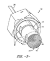
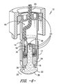
ここで図面を参照すると、図1〜図9及び図13〜図14は、本開示によるMCMセンサ組立体10の種々の実施形態を示す。本明細書で用いる場合、MCMは、一般に、複数の集積回路(IC)、半導体ダイ、及び/又はその他のディスクリートなダイ構成要素が通常は一体化された基板上に集積されて、使用時にはあたかも単一の構成要素であるかのように扱われるようになっている電子組立体(多数の導体端子又は「ピン」を有するパッケージなど)を指す。より詳細には、図1〜図3に示すように、統合型MCM組立体10の1つの実施形態を例証する。例えば、図1は、統合型MCM組立体10の斜視図を示し、図2は、統合型MCM組立体10の断面図を示し、図3は、統合型MCM組立体10の平面図を示す。図4〜図9は、MCMセンサ組立体10の別の実施形態を示し、ここでは電子機器は、短縮ケーブル25を介して接近して結合されているが一体化されていない。
With reference to the drawings here, FIGS. 1-9 and 13-14 show various embodiments of the
特に図1〜図3を参照すると、統合型MCM組立体10は、外側ハウジング14又はケーシングを有する少なくとも1つの静電気センサ12を含む。より詳細には、図示するように、外側ハウジング14は、センサ12を所望の位置に取り付けるか又はそれ以外の方法で固定するように構成された基部又は取付け部分17を含むことができる。例えば、図1及び図3に示すように、センサ12の取付け部分17は、静電気センサ12を所望の位置に取り付けるように構成された1又は2以上の貫通穴19を含むことができる。より詳細には、特定の実施形態において、貫通穴19の各々は、締結具(例えばねじ付きボルト)を受け入れてセンサ12を所望の位置に固定するように構成することができる。代替的に、静電気センサ12は、金属クリップ、クランプ、溶接ニクロム箔、溶接、又はそれに類する方法を含むが限定されない他のいずれかの適切な方法によって固定する又は取り付けることができる。
Particularly with reference to FIGS. 1-3, the
さらに、図示するように、静電気センサ12は、外側ハウジング14内に設けられた電極16を収容する。電極16は、所定の長さLで隔てられた第1の端部18及び第2の端部20を含む。特定の実施形態において、所定の長さLは、エンジン設置の幾何学的制約によって設定することができる。例えば、1つの実施形態において、所定の長さLは、電子26が電極16内で移動し、従って増幅器28(これは後述する)によって検出可能であるように、約1インチ乃至約3インチとすることができる。加えて、図示するように、電極16は、荷電粒子が矢印30で示すように検知面22を通過する場合に移動するようになった複数の電子26を包含する。このように、所定の長さLは、電子26が、その近くを流れる粒子の電荷に応じて検知面22に向かう方向及び/又は検知面22から遠ざかる方向に容易に流れることを可能にする。さらに、電極16の第1の端部18は、一般に外側ハウジング14内に固定され、他方、検知面22を含む第2の端部20は、外側ハウジング14の縁24と面一にすることができる。さらに、図1及び図2に示すように、電極16の検知面22は、所定の半径を有する湾曲面を含むことができる。
Further, as shown, the
加えて、図示した実施形態で示すように、静電気センサ12は、外側ハウジング14内に設けられた、電極16に電気的に結合された少なくとも1つの増幅器28を含むことができる。かかる実施形態において、増幅器28は、摂氏約−55度(℃)乃至約250℃、より好ましくは約150℃乃至約230℃の範囲の動作温度を有することができる。より詳細には、増幅器28は、シリコン・オン・インシュレータ(SOI)演算増幅器を含むことができる。例えば、特定の実施形態において、本開示の増幅器28は、米国ミネソタ州PlymouthのHoneywell,Incによって製造された広帯域SOI演算増幅器を含むことができる。かかる増幅器は、極めて低い漏れ電流を有し、高温で動作することが可能である。このように、本開示の増幅器28は、検知面22を通過する粒子レベルを電子移動の関数として検出又は測定するように構成される。
In addition, as shown in the illustrated embodiment, the
さらに、MCM組立体10は、外側ハウジング14内に設けられた、センサ12に例えば増幅器28を介して電気的に結合した集積回路基板32を含むことができる。より詳細には、図示するように、回路基板32は、電極16に隣接しかつ検知面22に対向するように構成することができる。付加的な実施形態において、回路基板32は、静電気センサ12の外側ハウジング14内のいずれかの適切な位置に配置することができる。さらに、本明細書で説明する場合の回路基板32は、センサ12の外側ハウジング14内で電子構成要素を支持して電気的に接続するあらゆる適切な回路基板を含むことができる。より詳細には、本開示の特定の回路基板は、非導電性基板上に積層された銅などの金属のシートからエッチングされた、導電性トラック、パッド、及び/又は他の特徴部を含むことができる。さらに、本開示の回路基板32は、片面、両面、又は多層とすることができる。従って、本明細書で説明する場合の回路基板32は、検知面22を通過する粒子レベルを示す1又は2以上の信号をコントローラ182に送るように構成され、これについてはより詳細に後述する。
Further, the
特に図2を参照すると、静電気センサ12はまた、1又は2以上の絶縁体又は絶縁層34を含むことができる。例えば、図示するように、静電気センサ12は、電極16と外側ハウジング14との間に1又は2以上の絶縁層34を含むことができる。加えて、静電気センサ12は、センサ構成要素を動作環境から絶縁するように取付け部分17内に1又2以上の絶縁層34を含むことができる。任意の数の絶縁層をセンサ12内のいずれかの適切な位置で使用することができることをさらに理解されたい。
In particular, with reference to FIG. 2, the
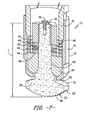
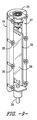
図4〜図9を参照すると、本開示のMCMセンサ組立体10の別の実施形態が例証される。より詳細には、図4に示すように、MCM組立体10は、ケーブル25を介して電子機器ハウジング15に結合された少なくとも1つの静電気センサ12を含む。さらに、図4〜図7に示すように、静電気センサ12は、外側ハウジング14又はケーシングを有する。より詳細には、図示するように、外側ハウジング14は、センサ12を所望の位置に取り付ける又はそれ以外の方法で固定するように構成された取付け部分17を含むことができる。例えば、図5〜図7に示すように、センサ12の取付け部分17は、静電気センサ12を所望の位置に固定する又は設置するように構成されたねじ外面又はBナットを含むことができる。さらに、図5及び図6に示すように、センサ12の外側ハウジング14はまた、センサの組み付け及び/又は取外し並びに設置を補助するように構成されたレンチ用平坦部(wrenching flat)21を含むこともできる。加えて、図6に示すように、センサ12の種々の構成要素は、1又は2以上のねじ接合部23を介して容易に固定することができる。
Referring to FIGS. 4-9, another embodiment of the
さらに、図4〜図7に一般的に示すように、静電気センサ12は、少なくとも部分的に外側ハウジング14内に設けられた電極16を有する。より詳細には、図7に示すように、電極16は、所定の長さLで隔てられた第1の端部18と第2の端部20とを含む。このように、電極16は、「電子湖(electron lake)」としての役割を果たし、その上を通過する荷電粒子は、その電荷に基づいて、「湖中」の電子を電極の第2の端部20に向かう方向又はそこから遠ざかる方向のいずれかに移動させる。電極16内のこの電子分布のシフトが増幅器28によって検出される。従ってこのような特徴は、センサ12の低周波数帯域を1ヘルツ(Hz)より下に拡張するように構成される。より詳細には、第1の端部18は、外側ハウジング14内に固定され、他方、第2の端部20は、外側ハウジング14の縁24を越えて延びた検知面22を含む。例えば、図示するように、第1の端部18は、少なくとも1つの固定具、例えばナット41を介して外側ハウジング14内に固定される。電極16の第1の端部18は、他のいずれかの適切な手段を用いてさらに固定することができることを理解されたい。加えて、図6及び図7に示すように、ケーブル25は、開放キャビティ45を通ってセンサ12の中に延びて、締結具36を介してセンサ12に固定される及び/又は電気的に結合することができる。より詳細には、ケーブル25の外側シースは、溶接ニクロムストリップを介してセンサ12の本体に接地することができ、他方、ケーブル25の内側導体は、締結具36を介してセンサ12に取り付けることができる。
Further, as generally shown in FIGS. 4-7, the
さらに、図5〜図7に示すように、電極16の検知面22は、所定の半径を有する湾曲面を含むことができる。特定の実施形態において、所定の半径を導入することで、検知面22の表面積を増大させ、及び/又はセンサ利得を増大させる。従って、特定の実施形態において、半径は、センサ組立体10を設置するのに利用可能な空間に応じたものとすることができる。1つの実施形態において、例えば、可能であれば検知面22の表面積を平坦な検知面と比べて約50%増大させる半径を導入することが望ましい場合がある。かかるセンサは、より大きい設置容積を必要とするが、粒子をより低濃度レベルで検出することが可能となる。
Further, as shown in FIGS. 5 to 7, the
さらに、図示するように、検知面22の湾曲面は、1又は2以上の突起38を有する刻み目付きの輪郭を有することができる。例えば、図示するように、突起38は、検知面22の表面積を約50%増大させる弓形の隆起に対応する。さらなる実施形態において、湾曲面及び/又は突起38は、検知面22の表面積を50%未満又は50%より多く増大させるように構成することができることを理解されたい。このように、湾曲面及び/又は突起38は、センサ12の流れストリームに提示される面積を最大限にしてセンサ12の感度を高めるように構成される。本明細書で説明される検知面22の突起38は、センサ12の感度を高めるように、いずれかの適切な形状及び/又はサイズをさらに有することができることを理解されたい。
Further, as shown, the curved surface of the
加えて、図6及び図7に示すように、センサ12の電極16は、荷電粒子が検知面22を通過した場合に移動するようになった複数の電子26を包含する。従って、電子26は、荷電ダスト粒子が検知面22を通過した場合に移動する又は流れるようになっている。より詳細には、電子26は、電極16内で、通過する粒子の電荷に基づいて、検知面22に向かう方向又は検知面22から遠ざかる方向のいずれかで移動する。
In addition, as shown in FIGS. 6 and 7, the
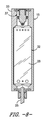
特に図4及び図8〜図9を参照すると、MCMセンサ組立体10の電子機器ハウジング15は、静電気センサ12とは分離しているが、それでもなおケーブル25を介して静電気センサ12に接近して結合される。より詳細には、特定の実施形態において、ケーブル25の長さは、約10インチ乃至約48インチ、より好ましくは約12インチ乃至約24インチの範囲とすることができる。これにより、電子機器は、外側ハウジング14内に組み込まれない場合であってもなおセンサ構成要素に接近して結合されており、高められたセンサ12の感度をもたらすようになっている。さらに、ケーブル25は、センサ12を電子機器ハウジング15内の適切な電子機器に電気的に結合するように構成されたいずれかの適切な電気ケーブルとすることができる。例えば、特定の実施形態において、ケーブル25は同軸ケーブルである。より詳細には、特定の実施形態において、ケーブル25は、一体型無機絶縁ハードラインケーブルを含むことができる。かかる実施形態において、電子機器ハウジング15をセンサ12から離れたより低温の位置に配設することができ、このことは後でより詳細に論じる。
In particular, referring to FIGS. 4 and 8-9, the
さらに、電子機器ハウジング15は、いずれかの適切な形状を有することができる。例えば、図示するように、電子機器ハウジング15は、略円筒形状を有する。さらに、図示するように、電子機器ハウジング15は、複数の締結具35によって互いに固定される2つの半部分33から形成することができる。このように、ケーブル25は、ケーブル25を半部分33の各々の間に配置し、半部分33を互いに固定することによって、回路基板32に電気的に結合することができる。加えて、図8〜図9に示すように、電子機器ハウジング15はまた、回路基板32に電気的に結合したピンコネクタ37を例えばケーブル接続の反対側に含むこともできる。
In addition, the
特に図4及び図8〜図9を参照すると、電子機器ハウジング15は、電極16に電気的に結合した少なくとも1つの増幅器28を収容するように構成される。図4〜図9の増幅器28(及び残りの電子機器)はセンサ12から分離しているので、MCMセンサ組立体10は、図1〜図3の統合型センサ組立体よりも高い、摂氏約250度(℃)乃至約550℃、より好ましくは約370℃乃至約538℃の範囲の動作温度を有することができる。さらに、増幅器28は、増幅器28がセンサ12の検知面22を通過する粒子レベルを電子移動の関数として検出又は測定するようになっている、本明細書で説明するようないずれかの増幅器を含むことができる。加えて、図示するように、電子機器ハウジング15はまた、ケーブル25を介してセンサ12に電気的に結合された回路基板32も収容する。上述のように、本明細書で説明される場合の回路基板32は、電子機器(例えば増幅器28など)を機械的に支持しかつセンサ12に電気的に接続するいずれかの適切な回路基板を含むことができる。より詳細には、本開示の特定の回路基板は、非導電性基板上に積層された銅などの金属のシートからエッチングされた、導電性トラック、パッド、及び/又は他の特徴部を含むことができる。
In particular, with reference to FIGS. 4 and 8-9, the
本開示の集積増幅器28は、極めて高感度であり、粒子レベルをより正確に検出することが可能である。より詳細には、特定の実施形態において、増幅器28は、約1フェムトアンペア乃至約5フェムトアンペア、より好ましくは約3フェムトアンペアの漏れ電流を含むことができる。従って、漏れ電流が低いことで、増幅器28の直流結合が容易になり、このことにより粒子レベルの低周波数変化を捕捉することが可能になる。さらに、本開示の電極16は、約1Gオームを超える、例えば約10Gオームのインピーダンスを有することができる。このように、電極16の高入力インピーダンスは、検知面22における電荷の小さい変化に対するセンサ感度を改善するように構成される。さらに、高入力インピーダンスはまた、検知された電荷が漏れ出して出力電圧を生成することができなくなることを防止することによって、静電気センサ12の低周波数応答を改善するようになっている。従って、本開示の静電気センサ12は、粒子質量基準で約7百万分の1を検出することが可能である。
The
特に図6及び図7を参照すると、静電気センサ12はまた、1又は2以上の絶縁体又は絶縁層34を含むことができる。例えば、図6及び図7に示すように、静電気センサ12は、電極16と外側ハウジング14との間にセラミック絶縁体34(アルミナなど)を含むことができる。任意の数の絶縁層をセンサ12内のいずれかの適切な位置で使用することができることをさらに理解されたい。
In particular, with reference to FIGS. 6 and 7, the
加えて、図示されるように、静電気センサ12は、外側ハウジング14内でセラミック絶縁体34とケーブル25との間で構成された1又は2以上の機械的締結具をさらに含むことができる。機械的締結具は、平ワッシャ、傾斜ワッシャ、ナット、ねじ、又はねじ山を含むことができる。より詳細には、図7に示すように、センサ12は、2つの内側平ワッシャ40とそれらの間に設けられた内側傾斜ワッシャ42とを含む。さらに、図示されるように、センサ12はまた、2つの外側平ワッシャとそれらの間に設けられた外側傾斜ワッシャ46とを含む。このように、傾斜ワッシャ42、46は、センサ12内でばねとして作用し、熱応力を解放する及び/又は高温で動作するときのセンサ12の種々の構成要素の膨張を可能にするようになっている。加えて、内側及び外側ワッシャのスタックは、高温においてセラミック絶縁体34に亀裂を入れることなく移動することを可能にするように、間隙48によって互いに分離される又は隔離されるようにすることができる。同様に、別の間隙49がセラミック絶縁体34と電極16との間に存在してもよく、それらの間の熱応力をさらに解放する。さらに図7を参照すると、上述のように、機械的締結具はまた、電極16を外側ハウジング14内に固定するように構成された、内側ワッシャ40、42に隣接したナット41を含むことができる。
In addition, as shown, the
ここで図10を参照すると、本開示による静電気センサ12に適した回路トポロジ50の1つの実施形態の概略図を示す。図示するように、回路50は、静電気センサ12から1又は2以上のセンサ入力を受け取る。例えば、センサ入力は、センサ12の電極16から受け取ることができる。入力は、次に第1の増幅器52に伝送される。より詳細には、センサ入力は、信号の静電放電(ESD)を防止する及び/又は低減するように、最初に抵抗器R1を通ることができる。さらに、図示するように、大きな抵抗値の抵抗器R2を入力経路(Pin1で示される)上に設けて、増幅器の漏れ電流を接地にバイパスするようになっている。Pin2から、入力信号のコピーが第2の増幅器54のPin1に伝送される。図示するように、信号は、抵抗器R3及びR4を通って進み、これが信号の利得を設定する。R5は、増幅器54のPin1の入力キャパシタンスを入力信号から切り離す。抵抗器の少なくとも1つ(例えばR3)はまた、それと並列に設けられた、増幅器52の帯域幅を制限するキャパシタC1を含むこともできる。キャパシタC2、C3、C4及びC5は、増幅器52及び54に対する減結合キャパシタとして働く。抵抗器R6及びR7は、増幅器出力をESDから保護するとともに回路を長い外部ケーブルから切り離す。第2の増幅器54の目的は、小さなセンサ信号をガードすることである。例えば、第2の増幅器54は、第1の増幅器52の入力と同じ電圧及び振幅で構成することができるが、低インピーダンスソース電流を供給する。このように、Pin3において示すように、第2の増幅器54は、センサ入力電圧をトラッキングして不要の電荷をセンサ入力から分流させることによって、センサ信号をガードする。従って、本発明の増幅器構成は、センサ入力電圧をトラッキングする第2の増幅器54によってガードされた利得を有する電圧フォロアを含み、センサ入力電圧をガードしてより良好な信号対雑音比をもたらす。
Here, with reference to FIG. 10, a schematic diagram of one embodiment of the
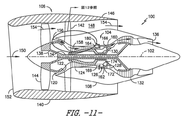
本明細書で説明する静電気センサ12は、あらゆる適切な用途を有することができる。例えば、特定の実施形態において、本開示の静電気センサ12は、航空機産業において、例えば航空機ガスタービンエンジン、並びに他のいずれかの適切なエンジン型式で利用することができる。より詳細には、図11は、本明細書で説明するような静電気センサ12の恩恵を受けることができるガスタービンエンジン100(高バイパスタイプ)の1つの実施形態の概略断面図を示す。図示するように、ガスタービンエンジン100は、貫通する長手方向中心軸線102を基準目的で有する。さらに図示するように、ガスタービンエンジン100は、好ましくは、全般的に符号104で示されるコアガスタービンエンジンセクションと、その上流に位置決めされたファンセクション106とを含む。コアエンジン104は、典型的には、環状入口120を定める略管状の外部ケーシング108を含む。外部ケーシング108は、さらに、コアエンジン104に入る空気の圧力を第1の圧力レベルまで高めるためのブースタ122を囲んで支持する。高圧多段軸流圧縮機124は、ブースタ122から加圧空気を受け取り、空気圧力をさらに高める。圧縮機124は、タービンエンジン100内で空気を方向付けて圧縮する機能を有する回転ブレード及び固定ベーンを含む。加圧空気は、燃焼器126へ流れ、ここで加圧空気ストリームに燃料を注入して点火し、加圧空気の温度及びエネルギーレベルを上昇させる。高エネルギーの燃焼生成物は、燃焼器126から、第1の(高圧)駆動シャフト130を通して高圧圧縮機124を駆動するための第1の(高圧)タービン128へ流れ、次いで、第1の駆動シャフト130と同軸の第2の(低圧)駆動シャフト134を通してブースタ122及びファンセクション106を駆動するための第2の(低圧)タービン132へ流れる。各タービン128及び132を駆動した後、燃焼生成物は、排出ノズル136を通ってコアエンジン104から出て、エンジン100のジェット推進推力の少なくとも一部をもたらす。
The
ファンセクション106は、環状ファンケーシング140によって取り囲まれた回転可能な軸流ファンロータ138を含む。ファンケーシング140は、複数の実質的に半径方向に延びた円周方向に離間した出口ガイドベーン142によってコアエンジン104から支持されることが認識されるであろう。このようにして、ファンケーシング140は、ファンロータ138及びファンロータブレード144を囲む。ファンケーシング140の下流セクション146は、コアエンジン104の外側部分の上に延びて、付加的なジェット推進推力をもたらす二次的な、すなわちバイパスの空気流通路148を定める。
The
流れの観点から見れば、矢印150で表される初期空気流は、ファンケーシング140への入口152を通ってガスタービンエンジン100に入ることが認識されるであろう。空気流はファンブレード144を通過して、通路148を通って移動する第1の空気流(矢印154で表される)と、ブースタ122に入る第2の空気流(矢印156で表される)とに分かれる。
From a flow point of view, it will be recognized that the initial airflow represented by the
第2の圧縮空気流156の圧力が高められて、矢印158で表されるように高圧圧縮機124に入る。燃焼器126内で燃料と混合されて燃焼した後、燃焼生生成物160は、燃焼器126から出て第1のタービン128を通って流れる。燃焼生生成物160は次に、第2のタービン132を通って流れ、排出ノズル136から出て、ガスタービンエンジン100の推力の少なくとも一部をもたらす。
The pressure of the second
引き続き図11を参照すると、燃焼器126は、長手方向中心軸線102と同軸の環状燃焼室162、並びに入口164及び出口166を含む。上記のように、燃焼器126は、高圧圧縮機排出出口169から加圧空気の環状ストリームを受け取る。この圧縮機排出空気流の一部は、混合器(図示せず)に入る。燃料は、燃料ノズル180から注入され、空気と混ざり合って燃料−空気混合物を形成し、これが燃焼のために燃焼室162に供給される。適切な点火器によって燃料−空気混合物の点火が達成され、得られた燃料ガス160は、環状の第1段タービンノズル172に向かって軸線方向に流入する。ノズル172は、環状流れチャネルによって定められ、これは、ガスの向きを変えてガスが第1のタービン128の第1段タービンブレードに角度を成して衝突するようにする複数の半径方向に延びた円周方向に離間したノズルベーン174を含む。第1のタービン128は、好ましくは第1の駆動シャフト130を介して高圧圧縮機124を回転させ、他方、低圧タービン132は、好ましくはブースタ122及びファンロータ138を第2の駆動シャフト134を介して駆動する。
Continuing with reference to FIG. 11, the
燃焼室162は、エンジンの外部ケーシング108内に収容され、燃料は、1又は2以上の燃料ノズル180によって燃焼室162内に供給される。より詳細には、液体燃料は、燃料ノズル180のステム内の1又は2以上の通路又は導管を通って輸送される。
The
動作中、ダスト及び他のタイプの粒子は、例えば入口152に入る空気から、ガスタービンエンジン100によって吸い込まれる。ダスト及び粒子の蓄積は、それらのレベルがエンジンのサービス時間、摩損、及び/又は他の保守スケジュールの評価において重要であるので、エンジン解析に対する重要な入力である。従って、上述のように、本開示の静電気センサ12は、かかるエンジン100内のダスト及び/又はデブリを検出するのに特に有用である。このように、本開示の静電気センサ12は、ガスタービンエンジン100のいずれかの適切な位置に配置することができる。例えば、本開示の静電気センサ12は、エンジン100のボアスコープポート、圧縮機入口167(図12)、圧縮機ブリード管(図13)、ブースタ入口165(図12)、又はエンジンのタービン若しくはアフタバーナ出口内に配置することができる。より詳細には、静電気センサ12は、旅客機が地球の赤道付近の高高度で遭遇する場合がある非常に微細な氷晶を検出することが可能である。かかる氷検出のために、センサ12をブースタ入口165又は圧縮機入口167に取り付けることができる。さらに、検知面22を非導電性エポキシコーティングで封止して、水又は溶けた氷が電極16をセンサ12の本体にショートさせることを防止することができる。
During operation, dust and other types of particles are sucked in by the
より詳細には、本開示の静電気センサ12は、所望の取付け位置に対応するあらゆる適切な形状を有することができることを理解されたい。例えば、特定の実施形態において、静電気センサ12は、ガスタービンエンジン100の既存の部位、穴、又は入口に取り付けられた検知面22がその内部表面と面一になるように構成された所定形状を有することができる。具体的には、図1〜図3及び図12に示すように、静電気センサ12は、略長円又は楕円形状を有することができる。かかる形状は一般に、エンジン100の既存の入口位置、例えば限定されないが圧縮機入口167及び/又はブースタ入口165などに対応する。代替的に、図4〜図7及び図13〜14に示すように、静電気センサ12は、エンジン100の圧縮機ブリード管170の入口に対応する略円筒形状を有することができる。さらに、図14に具体的に示すように、センサ12は、圧縮機ブリード管170に隣接して、検知面22がその内部の流路に入り込まない又は交差しないように取り付けることができる。
More specifically, it should be appreciated that the
図12、図13、及び図15を参照すると、MCMセンサ組立体10はまた、センサ12の電極16によって発生されるセンサ信号を受け取るように構成されたコントローラ182に通信可能に結合することできる。より詳細には、図15に示すように、本開示によるコントローラ182に含めることができる適切な構成要素の1つの実施形態のブロック図が示される。図示するように、コントローラ182は、種々のコンピュータ実装機能を実行する(例えば、本明細書で開示するように、方法、ステップ、計算等を実行する、及び関連データを格納する)ように構成された、1又は2以上のプロセッサ184及び関連付けられた記憶デバイス186を含むことができる。さらに、コントローラ182はまた、コントローラ182と静電気センサ12との間の通信を支援する通信モジュール188を含むことができる。さらに、通信モジュール188は、センサ12から伝送された信号をプロセッサ184が理解しかつ処理することができる信号に変換するセンサインタフェース190(例えば、1又は2以上のアナログデジタルコンバータ)を含むことができる。センサ12は、いずれかの適切な手段を用いて通信モジュール188に通信可能に結合することができることを認識されたい。例えば、図15に示すように、センサ12は、有線接続でセンサインタフェース190に結合される。しかしながら、他の実施形態において、センサ12は、例えば当該分野で公知のいずれかの適切な無線通信プロトコルを用いて無線接続でセンサインタフェース190に結合することができる。このように、プロセッサ184は、センサ12から1又は2以上の信号を受け取るように構成することができる。
With reference to FIGS. 12, 13, and 15, the
本明細書で用いる場合、「プロセッサ」という用語は、当該分野でコンピュータに含まれるものとして言及される集積回路のみならず、コントローラ、マイクロコントローラ、マイクロコンピュータ、プログラム可能論理コントローラ(PLC)、特定用途向け集積回路、及び他のプログラム可能回路をも指す。加えて、記憶デバイス186は、一般に、コンピュータ可読媒体(例えばランダムアクセスメモリ(RAM))、コンピュータ可読不揮発性媒体(例えばフラッシュメモリ)、クラウドストレージ、フロッピーディスク、コンパクトディスク読出し専用メモリ(CD−ROM)、光磁気ディスク(MOD)、デジタル多目的ディスク(DVD)及び/又は他の適切な記憶素子を含むがこれらに限定されない記憶素子を含むことができる。かかる記憶デバイス186は、一般に、プロセッサ184によって実装されたときにコントローラ182にガスタービンエンジン100の種々の機能を実行させる適切なコンピュータ可読命令を格納するように構成することができる。
As used herein, the term "processor" refers to integrated circuits referred to in the art as being included in a computer, as well as controllers, microcontrollers, microcomputers, programmable logic controllers (PLCs), and specific uses. Also refers to integrated circuits for, and other programmable circuits. In addition, the
ここで図16を参照すると、ガスタービンエンジン100、例えば航空機エンジン内の粒子を検出するための方法200の1つの実施形態のフロー図が示されている。202に示すように、方法200は、ガスタービンエンジン100内の1又は2以上の位置に上述のような少なくとも1つの静電気センサ12を設けることを含む。さらに、204に示すように、方法200は、各センサ12の検知面22を、1又は2以上の位置において粒子流路内に配置することを含む。従って、206に示すように、方法200はまた、各センサ12の増幅器28によって、ガスタービンエンジン100内の粒子レベルを電極16内の電子移動の関数として決定することを含む。208に示すように、方法200は、荷電ダスト粒子を検出したことに応答して、センサ12に接近して結合された回路基板86によって、粒子レベルを示す1又は2以上の信号を発生することを含む。
Here, with reference to FIG. 16, a flow diagram of one embodiment of the
1つの実施形態において、方法200は、静電気センサ12の各々の回路基板32によって、ガスタービンエンジン100のコントローラ182に信号を送信することをさらに含むことができる。このように、本明細書で説明されるセンサ12は、リアルタイムで正確な微粒子レベルデータをユーザに提供する。
In one embodiment, the
本明細書は、最良の形態を含む実施例を用いて本発明を開示し、更に、あらゆる当業者があらゆるデバイス又はシステムを実施及び利用すること及びあらゆる包含の方法を実施することを含む本発明を実施することを可能にする。本発明の特許保護される範囲は、請求項によって定義され、当業者であれば想起される他の実施例を含むことができる。このような他の実施例は、請求項の文言と差違のない構造要素を含む場合、或いは、請求項の文言と僅かな差違を有する均等な構造要素を含む場合には、本発明の範囲内にあるものとする。 The present invention discloses the present invention using examples including the best embodiments, and further comprises the present invention comprising the implementation and utilization of any device or system by any person skilled in the art and the implementation of any inclusion method. Allows you to carry out. The patent-protected scope of the invention is defined by the claims and may include other embodiments reminiscent of those skilled in the art. Such other embodiments are within the scope of the present invention if they include structural elements that are not different from the wording of the claim, or if they include equal structural elements that are slightly different from the wording of the claim. It shall be in.
10:MCMセンサ組立体
12:静電気センサ
14:外側ハウジング
15:電子機器ハウジング
16:電極
17:取付け部分
18:第1の端部
19:貫通穴
20:第2の端部
21:レンチ用平坦部
22:検知面
23:ねじ接合部
24:ハウジングの縁
25:ケーブル
26:電子
28:増幅器
30:矢印
32:回路基板
33:半部分
34:絶縁体
35:締結具
36:締結具
37:ピンコネクタ
38:突起
40:内側平ワッシャ
41:ナット
42:内側傾斜ワッシャ
45:開放キャビティ
46:外側傾斜ワッシャ
48:間隙
49:間隙
50:回路トポロジ
52:第1の増幅器
54:第2の増幅器
100:ガスタービンエンジン
102:中心軸線
104:コアエンジン
106:ファンセクション
108:外部ケーシング
120:環状入口
122:ブースタ
124:圧縮機
126:燃焼器
128:第1のタービン
130:第1の駆動シャフト
132:第2のタービン
134:第2の駆動シャフト
136:排出ノズル
138:ファンロータ
140:ファンケーシング
142:ガイドベーン
144:ロータブレード
146:下流セクション
148:空気流通路
150:矢印
152:入口
154:矢印
156:矢印
158:矢印
160:燃焼生成物
162:燃焼室
164:入口
165:ブースタ入口
166:出口
167:圧縮機入口
169:排出出口
170:圧縮機ブリード管
172:第1段タービンノズル
174:ノズルベーン
180:燃料ノズル
182:コントローラ
184:プロセッサ
186:記憶デバイス
188:通信モジュール
190:センサインタフェース
200:方法
202:方法ステップ
204:方法ステップ
206:方法ステップ
208:方法ステップ
10: MCM sensor assembly 12: Electrostatic sensor 14: Outer housing 15: Electronic equipment housing 16: Electrode 17: Mounting part 18: First end 19: Through hole 20: Second end 21: Flat part for wrench 22: Detection surface 23: Screw joint 24: Housing edge 25: Cable 26: Electronic 28: Amplifier 30: Arrow 32: Circuit board 33: Half part 34: Insulator 35: Fastener 36: Fastener 37: Pin connector 38: Protrusion 40: Inner flat washer 41: Nut 42: Inner inclined washer 45: Open cavity 46: Outer inclined washer 48: Gap 49: Gap 50: Circuit topology 52: First amplifier 54: Second amplifier 100: Gas Turbine engine 102: Central axis 104: Core engine 106: Fan section 108: External casing 120: Circular inlet 122: Booster 124: Compressor 126: Combustor 128: First turbine 130: First drive shaft 132: Second Turbine 134: Second drive shaft 136: Discharge nozzle 138: Fan rotor 140: Fan casing 142: Guide vane 144: Rotor blade 146: Downstream section 148: Air flow passage 150: Arrow 152: Inlet 154: Arrow 156: Arrow 158: Arrow 160: Combustion product 162: Combustion chamber 164: Inlet 165: Booster inlet 166: Outlet 167: Compressor inlet 169: Discharge outlet 170: Compressor bleed pipe 172: First stage turbine nozzle 174: Nozzle vane 180: Fuel Nozzle 182: Controller 184: Processor 186: Storage device 188: Communication module 190: Sensor interface 200: Method 202: Method step 204: Method step 206: Method step 208: Method step
Claims (20)
外側ハウジング(14)と、
前記外側ハウジング内に設けられ、所定の長さで隔てられた第1の端部(18)と第2の端部(20)とを備え、前記第2の端部は、前記外側ハウジングの縁(24)と実質的に面一の検知面(22)を備え、前記検知面を通過する1又は2以上の荷電粒子に対して前記第2の端部に向かう方向又は遠ざかる方向のいずれかに移動することによって応答するようになった複数の電子を含む、電極(16)と、
前記外側ハウジング内に設けられ、前記電極に電気的に結合され、前記検知面を通過する粒子レベルを電子移動の関数として検出するようになった増幅器(28)と、
前記外側ハウジング内に設けられ、前記センサに電気的に結合された回路基板(32)と、
を備え、
前記回路基板は、前記電極に隣接して配された、センサ組立体。 An integrated sensor assembly (10) comprising at least one electrostatic sensor (12), said electrostatic sensor.
Outer housing (14) and
It comprises a first end (18) and a second end (20) provided within the outer housing and separated by a predetermined length, the second end being the edge of the outer housing. It has a detection surface (22) that is substantially flush with (24), and either toward or away from the second end with respect to one or more charged particles passing through the detection surface. An electrode (16), which contains multiple electrons that have become responsive by moving, and
An amplifier (28) provided in the outer housing and electrically coupled to the electrodes to detect the particle level passing through the detection surface as a function of electron transfer.
A circuit board (32) provided in the outer housing and electrically coupled to the sensor.
Equipped with
The circuit board is a sensor assembly arranged adjacent to the electrodes.
外側ハウジング(14)と、
前記外側ハウジング内に設けられ、所定の長さで隔てられた第1の端部(18)と第2の端部(20)とを備え、前記第2の端部は、前記外側ハウジングの縁(24)と実質的に面一の検知面(22)を備え、前記検知面を通過する1又は2以上の荷電粒子に対して前記第2の端部に向かう方向又は遠ざかる方向のいずれかに移動することによって応答するようになった複数の電子を含む、電極(16)と、
前記外側ハウジング内に設けられ、前記電極に電気的に結合され、前記検知面を通過する粒子レベルを電子移動の関数として検出するようになった増幅器(28)と、
前記外側ハウジング内に設けられ、前記センサに電気的に結合された回路基板(32)と、
を備え、
前記電極の前記検知面は、所定の半径を有する湾曲面を備える、センサ組立体。 An integrated sensor assembly (10) comprising at least one electrostatic sensor (12), said electrostatic sensor.
Outer housing (14) and
It comprises a first end (18) and a second end (20) provided within the outer housing and separated by a predetermined length, the second end being the edge of the outer housing. It has a detection surface (22) that is substantially flush with (24), and either toward or away from the second end with respect to one or more charged particles passing through the detection surface. An electrode (16), which contains multiple electrons that have become responsive by moving, and
An amplifier (28) provided in the outer housing and electrically coupled to the electrodes to detect the particle level passing through the detection surface as a function of electron transfer.
A circuit board (32) provided in the outer housing and electrically coupled to the sensor.
Equipped with
The sensing surface of the electrode is provided with a curved surface having a predetermined radius, sensor assembly.
外側ハウジング(14)と、
前記外側ハウジング内に設けられ、所定の長さで隔てられた第1の端部(18)と第2の端部(20)とを備え、前記第2の端部は、前記外側ハウジングの縁(24)と実質的に面一の検知面(22)を備え、前記検知面を通過する1又は2以上の荷電粒子に対して前記第2の端部に向かう方向又は遠ざかる方向のいずれかに移動することによって応答するようになった複数の電子を含む、電極(16)と、
前記外側ハウジング内に設けられ、前記電極に電気的に結合され、前記検知面を通過する粒子レベルを電子移動の関数として検出するようになった増幅器(28)と、
前記外側ハウジング内に設けられ、前記センサに電気的に結合された回路基板(32)と、
を備え、
前記増幅器は、1フェムトアンペア乃至5フェムトアンペアの漏れ電流を有し、
前記回路基板における前記センサと接続される抵抗器は、1Gオームを超えるインピーダンスを有する、センサ組立体。 An integrated sensor assembly (10) comprising at least one electrostatic sensor (12), said electrostatic sensor.
Outer housing (14) and
It comprises a first end (18) and a second end (20) provided within the outer housing and separated by a predetermined length, the second end being the edge of the outer housing. It has a detection surface (22) that is substantially flush with (24), and either toward or away from the second end with respect to one or more charged particles passing through the detection surface. An electrode (16), which contains multiple electrons that have become responsive by moving, and
An amplifier (28) provided in the outer housing and electrically coupled to the electrodes to detect the particle level passing through the detection surface as a function of electron transfer.
A circuit board (32) provided in the outer housing and electrically coupled to the sensor.
Equipped with
The amplifier has a leakage current of 1 femtoamp乃optimum 5 femtoampere,
Resistor connected to the sensor in the circuit board has an impedance of greater than 1 G ohms, sensor assembly.
外側ハウジング(14)と、
前記外側ハウジング内に設けられ、第1の端部(18)と、検知面(22)を有する対
向した第2の端部(20)とを備え、前記検知面を通過する1又は2以上の荷電粒子に対して前記第2の端部に向かう方向又は遠ざかる方向のいずれかに移動することによって応答するようになった複数の電子を含む、電極(16)と、
前記外側ハウジング内に設けられ、前記電極に電気的に結合され、前記検知面を通過する粒子レベルを電子移動の関数として検出するようになった増幅器(28)と、
前記センサに電気的に結合された回路基板(32)と、
を備え、
前記回路基板は、前記電極に隣接して配された、センサ組立体。 An integrated multi-chip module (MCM) sensor assembly (10) comprising at least one electrostatic sensor (12), said electrostatic sensor.
Outer housing (14) and
One or more, provided in the outer housing, comprising a first end (18) and an opposed second end (20) having a detection surface (22) and passing through the detection surface. An electrode (16) containing a plurality of electrons that have become responsive to a charged particle by moving either towards or away from the second end.
An amplifier (28) provided in the outer housing and electrically coupled to the electrodes to detect the particle level passing through the detection surface as a function of electron transfer.
A circuit board (32) electrically coupled to the sensor and
Equipped with
The circuit board is a sensor assembly arranged adjacent to the electrodes.
外側ハウジング(14)と、
前記外側ハウジング内に少なくとも部分的に設けられ、所定の長さで隔てられた第1の端部(18)と第2の端部(20)とを備え、前記第1の端部は前記外側ハウジング内に固定され、前記第2の端部は前記外側ハウジングの縁(24)を越えて延びた検知面(22)を備え、前記検知面を通過する1又は2以上の荷電粒子に対して前記第2の端部に向かう方向又は遠ざかる方向のいずれかに移動することによって応答するようになった複数の電子を含む、電極(16)と、
ケーブル(25)を介して前記センサに電気的に結合された回路基板(32)と、
を備え、
前記検知面は、1又は2以上の突起を備える、センサ組立体。 A sensor assembly (10) comprising at least one electrostatic sensor (12), wherein the electrostatic sensor is.
Outer housing (14) and
It comprises a first end (18) and a second end (20) that are at least partially provided within the outer housing and are spaced apart by a predetermined length, the first end being said outer. Fixed within the housing, the second end comprises a sensing surface (22) extending beyond the edge (24) of the outer housing for one or more charged particles passing through the sensing surface. An electrode (16) containing a plurality of electrons that have become responsive by moving either towards or away from the second end .
And electrically coupled to the circuit board (32) to the sensor through a cable (25),
Equipped with
The detection surface is a sensor assembly comprising one or more protrusions.
Applications Claiming Priority (6)
| Application Number | Priority Date | Filing Date | Title |
|---|---|---|---|
| US15/007,282 | 2016-01-27 | ||
| US15/007,289 | 2016-01-27 | ||
| US15/007,289 US9714967B1 (en) | 2016-01-27 | 2016-01-27 | Electrostatic dust and debris sensor for an engine |
| US15/007,282 US10073008B2 (en) | 2016-01-27 | 2016-01-27 | Electrostatic sensor |
| US15/375,882 | 2016-12-12 | ||
| US15/375,882 US9651469B1 (en) | 2016-01-27 | 2016-12-12 | Electrostatic particle sensor |
Publications (2)
| Publication Number | Publication Date |
|---|---|
| JP2017134066A JP2017134066A (en) | 2017-08-03 |
| JP6973845B2 true JP6973845B2 (en) | 2021-12-01 |
Family
ID=57758551
Family Applications (1)
| Application Number | Title | Priority Date | Filing Date |
|---|---|---|---|
| JP2017008017A Active JP6973845B2 (en) | 2016-01-27 | 2017-01-20 | Electrostatic particle sensor |
Country Status (5)
| Country | Link |
|---|---|
| US (1) | US9651469B1 (en) |
| EP (2) | EP4001894A1 (en) |
| JP (1) | JP6973845B2 (en) |
| CN (2) | CN117092002A (en) |
| CA (1) | CA2955451A1 (en) |
Families Citing this family (2)
| Publication number | Priority date | Publication date | Assignee | Title |
|---|---|---|---|---|
| CN102985536B (en) * | 2010-04-14 | 2017-12-05 | Emd密理博公司 | Produce high-titer, high-purity virus stocks method and use its method |
| BR112020011307A2 (en) * | 2017-12-11 | 2020-11-17 | Hewlett-Packard Development Company, L.P. | detection of fluid particle concentrations |
Family Cites Families (10)
| Publication number | Priority date | Publication date | Assignee | Title |
|---|---|---|---|---|
| US4531402A (en) * | 1983-05-02 | 1985-07-30 | Battelle Development Corp. | Apparatus and method for measuring the concentration of large particles in a gas |
| US4531486A (en) * | 1983-05-02 | 1985-07-30 | Battelle Development Corporation | Apparatus and method for measuring the concentration of particles in a gas |
| CN1427898A (en) * | 2000-03-31 | 2003-07-02 | 伍斯特综合理工学院 | System for detecting and measuring inclusions |
| CN100592070C (en) * | 2006-04-25 | 2010-02-24 | 何宗彦 | Method for in-situ detection of aerosol particle concentration and detector thereof |
| WO2009140677A2 (en) * | 2008-05-16 | 2009-11-19 | Honeywell International Inc. | Particulate matter sensor |
| JP5438538B2 (en) * | 2010-02-08 | 2014-03-12 | 日本碍子株式会社 | Apparatus with abnormality determination function and abnormality determination method |
| GB2482480A (en) | 2010-08-02 | 2012-02-08 | Lockheed Martin Uk Insys Ltd | An electrostatic particle ingress inhibitor |
| US8459103B2 (en) * | 2011-06-24 | 2013-06-11 | United Technologies Corporation | IDMS signal processing to distinguish inlet particulates |
| US9010198B2 (en) * | 2011-07-29 | 2015-04-21 | United Technologies Corporation | Aircraft debris monitoring sensor assembly |
| GB201410283D0 (en) * | 2014-06-10 | 2014-07-23 | Cambridge Entpr Ltd | Sensing methods and apparatus |
-
2016
- 2016-12-12 US US15/375,882 patent/US9651469B1/en active Active
-
2017
- 2017-01-16 EP EP21202633.0A patent/EP4001894A1/en active Pending
- 2017-01-16 EP EP17151613.1A patent/EP3199940B1/en active Active
- 2017-01-19 CA CA2955451A patent/CA2955451A1/en active Pending
- 2017-01-20 JP JP2017008017A patent/JP6973845B2/en active Active
- 2017-01-25 CN CN202310851120.1A patent/CN117092002A/en active Pending
- 2017-01-25 CN CN201710055889.7A patent/CN107024418A/en active Pending
Also Published As
| Publication number | Publication date |
|---|---|
| EP4001894A1 (en) | 2022-05-25 |
| US9651469B1 (en) | 2017-05-16 |
| EP3199940B1 (en) | 2022-03-30 |
| CN107024418A (en) | 2017-08-08 |
| CN117092002A (en) | 2023-11-21 |
| CA2955451A1 (en) | 2017-07-27 |
| JP2017134066A (en) | 2017-08-03 |
| EP3199940A1 (en) | 2017-08-02 |
Similar Documents
| Publication | Publication Date | Title |
|---|---|---|
| JP6397515B2 (en) | Electrostatic dust and debris sensors for engines | |
| JP6937580B2 (en) | Electrostatic dust sensor for engine | |
| JP6973845B2 (en) | Electrostatic particle sensor | |
| US10436612B2 (en) | Encapsulated soft-lead capacitance probe for a gas turbine engine | |
| CN111323729A (en) | Arc detection and remaining life prediction for probe heater PHM | |
| US9320181B1 (en) | System and method for dissipating thermal energy away from electronic components in a rotatable shaft | |
| US9240660B1 (en) | Slip ring assembly and method for impedance matching high frequency signals across the slip ring assembly | |
| US11422081B2 (en) | Sensor for use in an exhaust gas stream of an internal combustion engine | |
| US20210003458A1 (en) | Method and system for measuring temperature in a gas turbine engine | |
| US9863269B2 (en) | System for packaging electronic components in a rotatable shaft | |
| CN215952796U (en) | Sensor and aircraft engine comprising same | |
| US10359383B2 (en) | Method of detecting galvanic insulation integrity | |
| FR3075877A1 (en) | SYSTEM FOR DETECTING A TEMPERATURE FAULT IN THE INTER-VEIN COMPARTMENT OF A DOUBLE FLOW TURBOREACTOR | |
| Liu et al. | The study of turbo-engine early fault detection technology based PHM sensor |
Legal Events
| Date | Code | Title | Description |
|---|---|---|---|
| RD03 | Notification of appointment of power of attorney |
Free format text: JAPANESE INTERMEDIATE CODE: A7423 Effective date: 20190402 |
|
| A621 | Written request for application examination |
Free format text: JAPANESE INTERMEDIATE CODE: A621 Effective date: 20200116 |
|
| A977 | Report on retrieval |
Free format text: JAPANESE INTERMEDIATE CODE: A971007 Effective date: 20210129 |
|
| A131 | Notification of reasons for refusal |
Free format text: JAPANESE INTERMEDIATE CODE: A131 Effective date: 20210215 |
|
| A521 | Request for written amendment filed |
Free format text: JAPANESE INTERMEDIATE CODE: A523 Effective date: 20210517 |
|
| TRDD | Decision of grant or rejection written | ||
| A01 | Written decision to grant a patent or to grant a registration (utility model) |
Free format text: JAPANESE INTERMEDIATE CODE: A01 Effective date: 20211004 |
|
| A61 | First payment of annual fees (during grant procedure) |
Free format text: JAPANESE INTERMEDIATE CODE: A61 Effective date: 20211028 |
|
| R150 | Certificate of patent or registration of utility model |
Ref document number: 6973845 Country of ref document: JP Free format text: JAPANESE INTERMEDIATE CODE: R150 |