JP6972811B2 - Manufacturing method of 3D model - Google Patents
Manufacturing method of 3D model Download PDFInfo
- Publication number
- JP6972811B2 JP6972811B2 JP2017174985A JP2017174985A JP6972811B2 JP 6972811 B2 JP6972811 B2 JP 6972811B2 JP 2017174985 A JP2017174985 A JP 2017174985A JP 2017174985 A JP2017174985 A JP 2017174985A JP 6972811 B2 JP6972811 B2 JP 6972811B2
- Authority
- JP
- Japan
- Prior art keywords
- dimensional model
- constituent
- layer
- solvent
- binder
- Prior art date
- Legal status (The legal status is an assumption and is not a legal conclusion. Google has not performed a legal analysis and makes no representation as to the accuracy of the status listed.)
- Active
Links
Images


Classifications
-
- B—PERFORMING OPERATIONS; TRANSPORTING
- B29—WORKING OF PLASTICS; WORKING OF SUBSTANCES IN A PLASTIC STATE IN GENERAL
- B29C—SHAPING OR JOINING OF PLASTICS; SHAPING OF MATERIAL IN A PLASTIC STATE, NOT OTHERWISE PROVIDED FOR; AFTER-TREATMENT OF THE SHAPED PRODUCTS, e.g. REPAIRING
- B29C64/00—Additive manufacturing, i.e. manufacturing of three-dimensional [3D] objects by additive deposition, additive agglomeration or additive layering, e.g. by 3D printing, stereolithography or selective laser sintering
- B29C64/10—Processes of additive manufacturing
- B29C64/165—Processes of additive manufacturing using a combination of solid and fluid materials, e.g. a powder selectively bound by a liquid binder, catalyst, inhibitor or energy absorber
-
- B—PERFORMING OPERATIONS; TRANSPORTING
- B22—CASTING; POWDER METALLURGY
- B22F—WORKING METALLIC POWDER; MANUFACTURE OF ARTICLES FROM METALLIC POWDER; MAKING METALLIC POWDER; APPARATUS OR DEVICES SPECIALLY ADAPTED FOR METALLIC POWDER
- B22F10/00—Additive manufacturing of workpieces or articles from metallic powder
- B22F10/10—Formation of a green body
- B22F10/16—Formation of a green body by embedding the binder within the powder bed
-
- B—PERFORMING OPERATIONS; TRANSPORTING
- B29—WORKING OF PLASTICS; WORKING OF SUBSTANCES IN A PLASTIC STATE IN GENERAL
- B29C—SHAPING OR JOINING OF PLASTICS; SHAPING OF MATERIAL IN A PLASTIC STATE, NOT OTHERWISE PROVIDED FOR; AFTER-TREATMENT OF THE SHAPED PRODUCTS, e.g. REPAIRING
- B29C64/00—Additive manufacturing, i.e. manufacturing of three-dimensional [3D] objects by additive deposition, additive agglomeration or additive layering, e.g. by 3D printing, stereolithography or selective laser sintering
- B29C64/20—Apparatus for additive manufacturing; Details thereof or accessories therefor
- B29C64/264—Arrangements for irradiation
-
- B—PERFORMING OPERATIONS; TRANSPORTING
- B29—WORKING OF PLASTICS; WORKING OF SUBSTANCES IN A PLASTIC STATE IN GENERAL
- B29C—SHAPING OR JOINING OF PLASTICS; SHAPING OF MATERIAL IN A PLASTIC STATE, NOT OTHERWISE PROVIDED FOR; AFTER-TREATMENT OF THE SHAPED PRODUCTS, e.g. REPAIRING
- B29C64/00—Additive manufacturing, i.e. manufacturing of three-dimensional [3D] objects by additive deposition, additive agglomeration or additive layering, e.g. by 3D printing, stereolithography or selective laser sintering
- B29C64/20—Apparatus for additive manufacturing; Details thereof or accessories therefor
- B29C64/295—Heating elements
-
- B—PERFORMING OPERATIONS; TRANSPORTING
- B29—WORKING OF PLASTICS; WORKING OF SUBSTANCES IN A PLASTIC STATE IN GENERAL
- B29C—SHAPING OR JOINING OF PLASTICS; SHAPING OF MATERIAL IN A PLASTIC STATE, NOT OTHERWISE PROVIDED FOR; AFTER-TREATMENT OF THE SHAPED PRODUCTS, e.g. REPAIRING
- B29C64/00—Additive manufacturing, i.e. manufacturing of three-dimensional [3D] objects by additive deposition, additive agglomeration or additive layering, e.g. by 3D printing, stereolithography or selective laser sintering
- B29C64/30—Auxiliary operations or equipment
- B29C64/379—Handling of additively manufactured objects, e.g. using robots
-
- B—PERFORMING OPERATIONS; TRANSPORTING
- B29—WORKING OF PLASTICS; WORKING OF SUBSTANCES IN A PLASTIC STATE IN GENERAL
- B29C—SHAPING OR JOINING OF PLASTICS; SHAPING OF MATERIAL IN A PLASTIC STATE, NOT OTHERWISE PROVIDED FOR; AFTER-TREATMENT OF THE SHAPED PRODUCTS, e.g. REPAIRING
- B29C71/00—After-treatment of articles without altering their shape; Apparatus therefor
- B29C71/02—Thermal after-treatment
-
- B—PERFORMING OPERATIONS; TRANSPORTING
- B29—WORKING OF PLASTICS; WORKING OF SUBSTANCES IN A PLASTIC STATE IN GENERAL
- B29C—SHAPING OR JOINING OF PLASTICS; SHAPING OF MATERIAL IN A PLASTIC STATE, NOT OTHERWISE PROVIDED FOR; AFTER-TREATMENT OF THE SHAPED PRODUCTS, e.g. REPAIRING
- B29C71/00—After-treatment of articles without altering their shape; Apparatus therefor
- B29C71/04—After-treatment of articles without altering their shape; Apparatus therefor by wave energy or particle radiation, e.g. for curing or vulcanising preformed articles
-
- B—PERFORMING OPERATIONS; TRANSPORTING
- B33—ADDITIVE MANUFACTURING TECHNOLOGY
- B33Y—ADDITIVE MANUFACTURING, i.e. MANUFACTURING OF THREE-DIMENSIONAL [3D] OBJECTS BY ADDITIVE DEPOSITION, ADDITIVE AGGLOMERATION OR ADDITIVE LAYERING, e.g. BY 3D PRINTING, STEREOLITHOGRAPHY OR SELECTIVE LASER SINTERING
- B33Y10/00—Processes of additive manufacturing
-
- B—PERFORMING OPERATIONS; TRANSPORTING
- B33—ADDITIVE MANUFACTURING TECHNOLOGY
- B33Y—ADDITIVE MANUFACTURING, i.e. MANUFACTURING OF THREE-DIMENSIONAL [3D] OBJECTS BY ADDITIVE DEPOSITION, ADDITIVE AGGLOMERATION OR ADDITIVE LAYERING, e.g. BY 3D PRINTING, STEREOLITHOGRAPHY OR SELECTIVE LASER SINTERING
- B33Y40/00—Auxiliary operations or equipment, e.g. for material handling
- B33Y40/20—Post-treatment, e.g. curing, coating or polishing
-
- B—PERFORMING OPERATIONS; TRANSPORTING
- B22—CASTING; POWDER METALLURGY
- B22F—WORKING METALLIC POWDER; MANUFACTURE OF ARTICLES FROM METALLIC POWDER; MAKING METALLIC POWDER; APPARATUS OR DEVICES SPECIALLY ADAPTED FOR METALLIC POWDER
- B22F10/00—Additive manufacturing of workpieces or articles from metallic powder
- B22F10/40—Structures for supporting workpieces or articles during manufacture and removed afterwards
- B22F10/43—Structures for supporting workpieces or articles during manufacture and removed afterwards characterised by material
-
- B—PERFORMING OPERATIONS; TRANSPORTING
- B22—CASTING; POWDER METALLURGY
- B22F—WORKING METALLIC POWDER; MANUFACTURE OF ARTICLES FROM METALLIC POWDER; MAKING METALLIC POWDER; APPARATUS OR DEVICES SPECIALLY ADAPTED FOR METALLIC POWDER
- B22F12/00—Apparatus or devices specially adapted for additive manufacturing; Auxiliary means for additive manufacturing; Combinations of additive manufacturing apparatus or devices with other processing apparatus or devices
- B22F12/30—Platforms or substrates
- B22F12/33—Platforms or substrates translatory in the deposition plane
-
- B—PERFORMING OPERATIONS; TRANSPORTING
- B22—CASTING; POWDER METALLURGY
- B22F—WORKING METALLIC POWDER; MANUFACTURE OF ARTICLES FROM METALLIC POWDER; MAKING METALLIC POWDER; APPARATUS OR DEVICES SPECIALLY ADAPTED FOR METALLIC POWDER
- B22F12/00—Apparatus or devices specially adapted for additive manufacturing; Auxiliary means for additive manufacturing; Combinations of additive manufacturing apparatus or devices with other processing apparatus or devices
- B22F12/30—Platforms or substrates
- B22F12/37—Rotatable
-
- B—PERFORMING OPERATIONS; TRANSPORTING
- B22—CASTING; POWDER METALLURGY
- B22F—WORKING METALLIC POWDER; MANUFACTURE OF ARTICLES FROM METALLIC POWDER; MAKING METALLIC POWDER; APPARATUS OR DEVICES SPECIALLY ADAPTED FOR METALLIC POWDER
- B22F12/00—Apparatus or devices specially adapted for additive manufacturing; Auxiliary means for additive manufacturing; Combinations of additive manufacturing apparatus or devices with other processing apparatus or devices
- B22F12/50—Means for feeding of material, e.g. heads
- B22F12/55—Two or more means for feeding material
-
- B—PERFORMING OPERATIONS; TRANSPORTING
- B29—WORKING OF PLASTICS; WORKING OF SUBSTANCES IN A PLASTIC STATE IN GENERAL
- B29C—SHAPING OR JOINING OF PLASTICS; SHAPING OF MATERIAL IN A PLASTIC STATE, NOT OTHERWISE PROVIDED FOR; AFTER-TREATMENT OF THE SHAPED PRODUCTS, e.g. REPAIRING
- B29C35/00—Heating, cooling or curing, e.g. crosslinking or vulcanising; Apparatus therefor
- B29C35/02—Heating or curing, e.g. crosslinking or vulcanizing during moulding, e.g. in a mould
- B29C35/08—Heating or curing, e.g. crosslinking or vulcanizing during moulding, e.g. in a mould by wave energy or particle radiation
- B29C35/0805—Heating or curing, e.g. crosslinking or vulcanizing during moulding, e.g. in a mould by wave energy or particle radiation using electromagnetic radiation
- B29C2035/0822—Heating or curing, e.g. crosslinking or vulcanizing during moulding, e.g. in a mould by wave energy or particle radiation using electromagnetic radiation using IR radiation
-
- B—PERFORMING OPERATIONS; TRANSPORTING
- B29—WORKING OF PLASTICS; WORKING OF SUBSTANCES IN A PLASTIC STATE IN GENERAL
- B29C—SHAPING OR JOINING OF PLASTICS; SHAPING OF MATERIAL IN A PLASTIC STATE, NOT OTHERWISE PROVIDED FOR; AFTER-TREATMENT OF THE SHAPED PRODUCTS, e.g. REPAIRING
- B29C71/00—After-treatment of articles without altering their shape; Apparatus therefor
- B29C71/02—Thermal after-treatment
- B29C2071/022—Annealing
-
- Y—GENERAL TAGGING OF NEW TECHNOLOGICAL DEVELOPMENTS; GENERAL TAGGING OF CROSS-SECTIONAL TECHNOLOGIES SPANNING OVER SEVERAL SECTIONS OF THE IPC; TECHNICAL SUBJECTS COVERED BY FORMER USPC CROSS-REFERENCE ART COLLECTIONS [XRACs] AND DIGESTS
- Y02—TECHNOLOGIES OR APPLICATIONS FOR MITIGATION OR ADAPTATION AGAINST CLIMATE CHANGE
- Y02P—CLIMATE CHANGE MITIGATION TECHNOLOGIES IN THE PRODUCTION OR PROCESSING OF GOODS
- Y02P10/00—Technologies related to metal processing
- Y02P10/25—Process efficiency
Landscapes
- Engineering & Computer Science (AREA)
- Chemical & Material Sciences (AREA)
- Materials Engineering (AREA)
- Manufacturing & Machinery (AREA)
- Physics & Mathematics (AREA)
- Mechanical Engineering (AREA)
- Optics & Photonics (AREA)
- Thermal Sciences (AREA)
- Toxicology (AREA)
- Health & Medical Sciences (AREA)
- Robotics (AREA)
- Powder Metallurgy (AREA)
- Producing Shaped Articles From Materials (AREA)
Description
本発明は、三次元造形物の製造方法に関する。 The present invention relates to a method for manufacturing a three-dimensional model.
従来から、様々な三次元造形物を製造する製造方法が実施されている。このうち、複数の層を積層して三次元造形物を製造する三次元造形物の製造方法がある。
例えば、特許文献1には、光硬化性樹脂に選択的に光を照射することにより複数の硬化樹脂層を形成することで三次元造形物を製造する三次元造形物の製造方法が開示されている。
Conventionally, a manufacturing method for manufacturing various three-dimensional shaped objects has been implemented. Among these, there is a method for manufacturing a three-dimensional model in which a plurality of layers are laminated to produce a three-dimensional model.
For example, Patent Document 1 discloses a method for manufacturing a three-dimensional model, which produces a three-dimensional model by forming a plurality of cured resin layers by selectively irradiating a photocurable resin with light. There is.
三次元造形物は、様々な材料で構成でき、例えば、金属やセラミックスなどで三次元造形物の形状を形成し、三次元造形物の形状が完成した後にそれを脱脂したり焼結させたりする場合がある。また、三次元造形物を構成する粉末と溶媒とバインダーとを含む組成物を用いて複数の層を積層して三次元造形物を製造する場合、溶媒の揮発などに伴って、各層において脱脂や焼結の前に溶媒及びバインダーの分布が偏り、三次元造形物の積層物内で応力が発生することがある。これは、各層における溶媒の除去速度(揮発速度など)が各層の端部側(速い)と中央部側(遅い)とで異なる(偏る)ことに起因する。溶媒の除去速度の偏りに伴って溶媒及びバインダーの分布が偏ると、三次元造形物の積層物内で、各層の端部側から中央部側に向かう応力が発生し、このような状態で脱脂や焼結を実行すると、三次元造形物の積層物に該応力に起因する反りなどが発生し、変形してしまう場合がある。 The 3D model can be composed of various materials. For example, the shape of the 3D model is formed from metal or ceramics, and after the shape of the 3D model is completed, it is degreased or sintered. In some cases. In addition, when a plurality of layers are laminated using a composition containing a powder, a solvent, and a binder constituting the three-dimensional model to produce a three-dimensional model, degreasing or degreasing is performed in each layer due to volatilization of the solvent. Prior to sintering, the distribution of solvent and binder may be biased and stress may occur in the laminate of the 3D model. This is because the solvent removal rate (volatilization rate, etc.) in each layer differs (biased) between the end side (fast) and the center side (slow) of each layer. When the distribution of the solvent and the binder is biased due to the bias in the removal rate of the solvent, stress is generated from the end side to the center side of each layer in the laminate of the three-dimensional model, and degreasing is performed in such a state. When or sintering is performed, the laminate of the three-dimensional model may be warped due to the stress and may be deformed.
そこで、本発明の目的は、複数の層が積層されてなる三次元造形物を製造する際に、脱脂や焼結に伴って三次元造形物の積層物が変形することを抑制することである。 Therefore, an object of the present invention is to suppress deformation of the three-dimensional modeled product due to degreasing and sintering when manufacturing a three-dimensional model product in which a plurality of layers are laminated. ..
上記課題を解決するための本発明の第1の態様の三次元造形物の製造方法は、複数の層が積層されてなる三次元造形物を製造する三次元造形物の製造方法であって、前記三次元造形物を構成する粉末と、溶媒と、バインダーと、を含む組成物を用いて、前記層を形成する層形成工程と、前記層に含まれる前記溶媒を除去する溶媒除去工程と、前記層形成工程と前記溶媒除去工程とが実行されることで得られた前記層に前記バインダーのガラス転移温度以上の温度の熱を加える熱処理工程と、前記熱処理工程で熱処理された前記三次元造形物の積層物に対して、脱脂及び焼結の少なくともいずれかを実行する加熱工程と、を有することを特徴とする。 The method for manufacturing a three-dimensional model according to the first aspect of the present invention for solving the above problems is a method for manufacturing a three-dimensional model in which a plurality of layers are laminated. A layer forming step of forming the layer by using a composition containing a powder, a solvent, and a binder constituting the three-dimensional model, and a solvent removing step of removing the solvent contained in the layer. A heat treatment step of applying heat at a temperature equal to or higher than the glass transition temperature of the binder to the layer obtained by executing the layer forming step and the solvent removing step, and the three-dimensional modeling heat-treated in the heat treatment step. It is characterized by having a heating step of performing at least one of degreasing and sintering on a laminate of objects.
本態様によれば、脱脂及び焼結の少なくともいずれかを実行する加熱工程の前に、三次元造形物の積層物を構成する層に熱を加える熱処理工程を実行する。このため、溶媒除去工程で溶媒及びバインダーの分布が偏ったとしても、該熱処理工程によりその偏り(該偏りに伴う応力)を低減又は解消できる。したがって、脱脂や焼結を実行する前に三次元造形物の積層物内での応力を低減又は解消でき、加熱工程(脱脂や焼結)に伴って三次元造形物の積層物が変形することを抑制することができる。 According to this aspect, before the heating step of performing at least one of degreasing and sintering, a heat treatment step of applying heat to the layers constituting the laminate of the three-dimensional model is performed. Therefore, even if the distribution of the solvent and the binder is biased in the solvent removing step, the bias (stress associated with the bias) can be reduced or eliminated by the heat treatment step. Therefore, stress in the laminate of the three-dimensional model can be reduced or eliminated before degreasing or sintering is performed, and the laminate of the three-dimensional model is deformed with the heating process (defatting or sintering). Can be suppressed.
本発明の第2の態様の三次元造形物の製造方法は、前記第1の態様において、前記熱処理工程は、前記層形成工程と前記溶媒除去工程とが実行されることで得られた複数の前記層からなる前記三次元造形物の積層物に前記バインダーのガラス転移温度以上の温度の熱を加えることを特徴とする。 The method for producing a three-dimensional model according to the second aspect of the present invention is a plurality of methods obtained by executing the layer forming step and the solvent removing step in the heat treatment step in the first aspect. It is characterized in that heat of a temperature equal to or higher than the glass transition temperature of the binder is applied to the laminate of the three-dimensional model composed of the layers.
本態様によれば、熱処理工程は複数の層からなる三次元造形物の積層物に熱を加えるので、熱処理工程の実行回数を減らすことができ、三次元造形物の製造効率(製造速度)を高めることができる。 According to this aspect, since the heat treatment step applies heat to the laminate of the three-dimensional shaped object composed of a plurality of layers, the number of executions of the heat treatment step can be reduced, and the manufacturing efficiency (manufacturing speed) of the three-dimensional shaped object can be improved. Can be enhanced.
本発明の第3の態様の三次元造形物の製造方法は、前記第2の態様において、前記熱処理工程は、前記バインダーの軟化点以下の温度の熱を加えることを特徴とする。 The method for producing a three-dimensional model according to a third aspect of the present invention is characterized in that, in the second aspect, the heat treatment step applies heat at a temperature equal to or lower than the softening point of the binder.
本態様によれば、熱処理工程はバインダーの軟化点以下の温度の熱を加えるので、熱処理工程に伴ってバインダーが軟化して三次元造形物の積層物が変形することを抑制できる。 According to this aspect, since the heat treatment step applies heat at a temperature equal to or lower than the softening point of the binder, it is possible to prevent the binder from softening and deforming the laminate of the three-dimensional model with the heat treatment step.
本発明の第4の態様の三次元造形物の製造方法は、前記第2または第3の態様において、前記組成物に前記バインダーが複数種類含まれていた場合、前記熱処理工程は、前記バインダーのうちの最高のガラス転移温度以上の温度の熱を加えることを特徴とする。 In the method for producing a three-dimensional model according to the fourth aspect of the present invention, when a plurality of types of the binder are contained in the composition in the second or third aspect, the heat treatment step is performed on the binder. It is characterized by applying heat at a temperature higher than the highest glass transition temperature.
本態様によれば、バインダーが複数種類含まれていた場合でも、バインダーの分布の偏りを特に効果的に低減又は解消できる。 According to this aspect, even when a plurality of types of binders are contained, the bias of the distribution of the binders can be particularly effectively reduced or eliminated.
本発明の第5の態様の三次元造形物の製造方法は、前記第1から第4のいずれか1つの態様において、前記溶媒除去工程は、前記層形成工程が1回行われる毎に実行されることを特徴とする。 In the method for producing a three-dimensional model according to the fifth aspect of the present invention, in any one of the first to fourth aspects, the solvent removing step is executed every time the layer forming step is performed. It is characterized by that.
本態様によれば、溶媒除去工程を1回行う毎に層形成工程が実行されるので、溶媒除去工程に伴うバインダーの分布の偏りを特に効果的に低減できる。 According to this aspect, since the layer forming step is executed every time the solvent removing step is performed, the bias of the binder distribution due to the solvent removing step can be particularly effectively reduced.
本発明の第6の態様の三次元造形物の製造方法は、前記第1から第4のいずれか1つの態様において、前記溶媒除去工程は、前記層形成工程が複数回行われてから実行されることを特徴とする。 In the method for producing a three-dimensional model according to the sixth aspect of the present invention, in any one of the first to fourth aspects, the solvent removing step is executed after the layer forming step is performed a plurality of times. It is characterized by that.
本態様によれば、溶媒除去工程を複数回行ってから層形成工程が実行されるので、三次元造形物の製造効率(製造速度)を高めることができる。 According to this aspect, since the layer forming step is executed after performing the solvent removing step a plurality of times, the manufacturing efficiency (manufacturing speed) of the three-dimensional model can be improved.
以下、図面を参照して、本発明に係る実施形態を説明する。
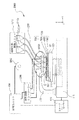
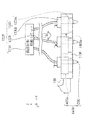
図1〜図4は本発明の一の実施形態に係る三次元造形物の製造装置の構成を示す概略構成図である。
ここで、本実施形態の三次元造形物の製造装置は、2種類の材料供給部(ヘッドベース)を備えている。このうち、図1及び図2は、一の材料供給部(三次元造形物の構成材料を供給する材料供給部)のみを表した図である。また、図3及び図4は、別の一の材料供給部(三次元造形物を形成する際に該三次元造形物を支持する支持部を形成する支持部形成用材料を供給する材料供給部)のみを表した図である。
なお、本明細書における「三次元造形」とは、いわゆる立体造形物を形成することを示すものであって、例えば、平板状、いわゆる二次元形状の形状であっても厚さを有する形状を形成することも含まれる。また、「支持する」とは、下側から支持する場合の他、横側から支持する場合や、場合によっては上側から支持する場合も含む意味である。
また、本実施例の構成材料は、三次元造形物を構成する粉末粒子と溶媒と該溶媒に可溶なバインダーとを含む三次元造形用ペースト(ペースト状の組成物)である。そして、本実施例の支持部形成用材料は、支持層形成用粒子と溶媒と該溶媒に可溶なバインダーとを含む三次元造形用ペースト(ペースト状の組成物)である。
Hereinafter, embodiments according to the present invention will be described with reference to the drawings.
1 to 4 are schematic configuration diagrams showing a configuration of a three-dimensional model manufacturing apparatus according to an embodiment of the present invention.
Here, the three-dimensional model manufacturing apparatus of the present embodiment includes two types of material supply units (head bases). Of these, FIGS. 1 and 2 are views showing only one material supply unit (material supply unit that supplies constituent materials of a three-dimensional model). Further, FIGS. 3 and 4 show another material supply unit (a material supply unit that supplies a material for forming a support portion that forms a support portion that supports the three-dimensional model when forming the three-dimensional model). ) Only.
In addition, "three-dimensional modeling" in the present specification indicates that a so-called three-dimensional model is formed, and for example, a flat plate shape, that is, a shape having a thickness even if it is a so-called two-dimensional shape. It also includes forming. Further, "supporting" means not only the case of supporting from the lower side, but also the case of supporting from the side side and, in some cases, the case of supporting from the upper side.
Further, the constituent material of this example is a paste for three-dimensional modeling (paste-like composition) containing powder particles constituting the three-dimensional model, a solvent, and a binder soluble in the solvent. The material for forming the support portion of this example is a three-dimensional modeling paste (paste-like composition) containing particles for forming a support layer, a solvent, and a binder soluble in the solvent.
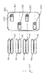
図1及び図3に示す三次元造形物の製造装置2000(以下、形成装置2000という)は、基台110と、基台110に備える駆動手段としての駆動装置111によって、図示するX,Y,Z方向の移動、あるいはZ軸を中心とする回転方向に駆動可能に備えられたステージ120を備えている。
そして、図1及び図2で表されるように、一方の端部が基台110に固定され、他方の端部に構成材料を吐出する構成材料吐出部1230を備えるヘッドユニット1400を複数保持するヘッドベース1100が保持固定される、ヘッドベース支持部130を備えている。
また、図3及び図4で表されるように、一方の端部が基台110に固定され、他方の端部に三次元造形物を支持する支持層形成用材料を吐出する支持層形成用材料吐出部1730を備えるヘッドユニット1900を複数保持するヘッドベース1600が保持固定される、ヘッドベース支持部730と、を備えている。
ここで、ヘッドベース1100と、ヘッドベース1600とは、XY平面において並列に設けられている。
なお、構成材料吐出部1230と支持層形成用材料吐出部1730とは同様の構成のものである。ただし、このような構成に限定されない。
The three-dimensional model manufacturing apparatus 2000 (hereinafter referred to as a forming apparatus 2000) shown in FIGS. 1 and 3 includes X, Y, illustrated by a
Then, as shown in FIGS. 1 and 2, one end is fixed to the
Further, as shown in FIGS. 3 and 4, one end is fixed to the
Here, the
The constituent
ステージ120上には、三次元造形物500が形成される過程での層501、502及び503が形成される。三次元造形物500の形成には、電磁波照射部1000などによる熱エネルギーの照射がなされるため、ステージ120の熱からの保護のため、耐熱性を有する試料プレート121を用いて、試料プレート121の上に三次元造形物500を形成してもよい。本実施形態の試料プレート121は頑丈で製造の容易な金属製のものである。しかしながら、試料プレート121としては、例えばセラミック板を用いることで、高い耐熱性を得ることができ、更に脱脂や焼結などがされる三次元造形物の構成材料との反応性も低く、三次元造形物500の変質を防止することができる。なお、図1及び図3では、説明の便宜上、層501、502及び503の3層を例示したが、所望の三次元造形物500の形状まで(図1及び図3中の層50nまで)積層される。
ここで、層501、502、503、・・・50nは、各々、支持層形成用材料吐出部1730から吐出される支持層形成用材料で形成される支持層300と、構成材料吐出部1230から吐出される構成材料で形成される構成層310と、で構成される。
なお、本実施形態の形成装置2000は、三次元造形物500の構成材料のほか支持層形成用材料を用いて層501、502、503、・・・50nと複数の層を形成可能な三次元造形物の製造装置であるが、支持層形成用材料を用いることなく複数の層を形成可能な三次元造形物の製造装置であってもよい。
Here, the
The forming
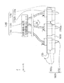
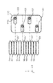
また、図2は、図1に示すヘッドベース1100を示すC部拡大概念図である。図2に示すように、ヘッドベース1100は、複数のヘッドユニット1400が保持されている。詳細は後述するが、1つのヘッドユニット1400は、構成材料供給装置1200に備える構成材料吐出部1230が保持治具1400aに保持されることで構成される。構成材料吐出部1230は、吐出ノズル1230aと、材料供給コントローラー1500によって吐出ノズル1230aから構成材料を吐出させる吐出駆動部1230bと、を備えている。
Further, FIG. 2 is an enlarged conceptual diagram of part C showing the
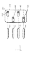
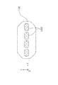
図4は、図3に示すヘッドベース1600を示すC’部拡大概念図である。図4に示すように、ヘッドベース1600は、複数のヘッドユニット1900が保持されている。ヘッドユニット1900は、支持層形成用材料供給装置1700に備える支持層形成用材料吐出部1730が保持治具1900aに保持されることで構成される。支持層形成用材料吐出部1730は、吐出ノズル1730aと、材料供給コントローラー1500によって吐出ノズル1730aから支持層形成用材料を吐出させる吐出駆動部1730bと、を備えている。
FIG. 4 is an enlarged conceptual diagram of a C'section showing the
図1及び図2で表されるように、構成材料吐出部1230は、ヘッドベース1100に保持されるヘッドユニット1400それぞれに対応させた構成材料を収容した構成材料供給ユニット1210と供給チューブ1220により接続されている。そして、所定の構成材料が構成材料供給ユニット1210から構成材料吐出部1230に供給される。構成材料供給ユニット1210には、本実施形態に係る形成装置2000によって造形される三次元造形物500の構成材料が構成材料収容部1210aに収容され、個々の構成材料収容部1210aは、供給チューブ1220によって、個々の構成材料吐出部1230に接続されている。このように、個々の構成材料収容部1210aを備えることにより、ヘッドベース1100から、複数の異なる種類の材料を供給することができる。
As shown in FIGS. 1 and 2, the constituent
図3及び図4で表されるように、支持層形成用材料吐出部1730は、ヘッドベース1600に保持されるヘッドユニット1900それぞれに対応させた支持層形成用材料を収容した支持層形成用材料供給ユニット1710と供給チューブ1720により接続されている。そして、所定の支持層形成用材料が支持層形成用材料供給ユニット1710から支持層形成用材料吐出部1730に供給される。支持層形成用材料供給ユニット1710には、三次元造形物500を造形する際の支持層を構成する支持層形成用材料が支持層形成用材料収容部1710aに収容され、個々の支持層形成用材料収容部1710aは、供給チューブ1720によって、個々の支持層形成用材料吐出部1730に接続されている。このように、個々の支持層形成用材料収容部1710aを備えることにより、ヘッドベース1600から、複数の異なる種類の支持層形成用材料を供給することができる。
なお、本実施例の形成装置2000で使用される構成材料及び支持層形成用材料としての各々の三次元造形用ペーストについての詳細は後述する。
As shown in FIGS. 3 and 4, the support layer forming
The details of the constituent materials used in the forming
形成装置2000には、図示しない、例えばパーソナルコンピューター等のデータ出力装置から出力される三次元造形物の造形用データに基づいて、上述したステージ120、構成材料供給装置1200に備える構成材料吐出部1230、並びに、支持層形成用材料供給装置1700に備える支持層形成用材料吐出部1730を制御する制御手段としての制御ユニット400を備えている。そして、制御ユニット400には、図示しないが、ステージ120及び構成材料吐出部1230が連携して駆動及び動作するよう制御し、ステージ120及び支持層形成用材料吐出部1730が連携して駆動及び動作するよう制御する制御部を備えている。
The forming
基台110に移動可能に備えられているステージ120は、制御ユニット400からの制御信号に基づき、ステージコントローラー410においてステージ120の移動開始と停止、移動方向、移動量、移動速度などを制御する信号が生成され、基台110に備える駆動装置111に送られ、図示するX、Y、Z方向にステージ120が移動する。ヘッドユニット1400に備える構成材料吐出部1230では、制御ユニット400からの制御信号に基づき、材料供給コントローラー1500において構成材料吐出部1230に備える吐出駆動部1230bにおける吐出ノズル1230aからの材料吐出量などを制御する信号が生成され、生成された信号により吐出ノズル1230aから所定量の構成材料が吐出される。
同様に、ヘッドユニット1900に備える支持層形成用材料吐出部1730では、制御ユニット400からの制御信号に基づき、材料供給コントローラー1500において支持層形成用材料吐出部1730に備える吐出駆動部1730bにおける吐出ノズル1730aからの材料吐出量などを制御する信号が生成され、生成された信号により吐出ノズル1730aから所定量の支持層形成用材料が吐出される。
また、電磁波照射部1000も、制御ユニット400による制御で、ステージ120(試料プレート121)に形成された三次元造形物500の層501、502、503、・・・50nに向けて、電磁波を照射可能な構成になっている。
The
Similarly, in the support layer forming
Further, the electromagnetic
次に、ヘッドユニット1400についてさらに詳細に説明する。なお、ヘッドユニット1900は、ヘッドユニット1400と同様の構成である。このため、ヘッドユニット1900についての詳細な構成の説明は省略する。
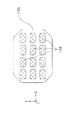
図5、並びに、図6〜図8は、ヘッドベース1100に複数保持されるヘッドユニット1400及び構成材料吐出部1230の保持形態の一例を示し、このうち図6〜図8は、図2に示す矢印D方向からのヘッドベース1100の外観図である。
Next, the
5 and 6 to 8 show an example of a holding form of the
図5に示すように、ヘッドベース1100に複数のヘッドユニット1400が、図示しない固定手段によって保持されている。また、図6〜図8で表されるように、本実施形態に係る形成装置2000のヘッドベース1100では、図下方より第1列目のヘッドユニット1401、第2列目のヘッドユニット1402、第3列目のヘッドユニット1403、そして第4列目のヘッドユニット1404の、4ユニットが千鳥状(互い違い)に配置されたヘッドユニット1400を備えている。そして、図6で表されるように、ステージ120をヘッドベース1100に対してX方向に移動させながら各ヘッドユニット1400から構成材料を吐出させて構成層構成部50(構成層構成部50a、50b、50c及び50d)が形成される。構成層構成部50の形成手順については後述する。
なお、図示しないが、それぞれのヘッドユニット1401〜1404に備える構成材料吐出部1230は、吐出駆動部1230bを介して構成材料供給ユニット1210に供給チューブ1220で繋がれる構成となっている。
As shown in FIG. 5, a plurality of
Although not shown, the component
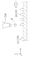
図5に示すように、構成材料吐出部1230は吐出ノズル1230aから、ステージ120上に載置された試料プレート121上に向けて三次元造形物の構成材料(ペースト状の組成物)である材料Mが吐出される。ヘッドユニット1401では、材料Mが液滴状で吐出される吐出形態を例示し、ヘッドユニット1402では、材料Mが連続体状で供給される吐出形態を例示している。材料Mの吐出形態は、液滴状であっても連続体状であっても、どちらでもよいが、本実施形態では材料Mは液滴状で吐出される形態により説明する。
As shown in FIG. 5, the constituent
吐出ノズル1230aから液滴状に吐出された材料Mは、略重力方向に飛翔し、試料プレート121上に着弾する。ステージ120は移動し、着弾した材料Mにより構成層構成部50が形成される。この構成層構成部50の集合体が、試料プレート121上に形成される三次元造形物500の構成層310(図1参照)として形成される。
The material M discharged in the form of droplets from the
次に、構成層構成部50の形成手順について、図6〜図8、並びに、図9及び図10を用いて説明する。
図6〜図8は、本実施形態のヘッドユニット1400の配置と、構成層構成部50の形成形態と、の関係を概念的に説明する平面図である。そして、図9及び図10は、構成層構成部50の形成形態を概念的に表す側面図である。
Next, the procedure for forming the constituent layer
6 to 8 are plan views conceptually explaining the relationship between the arrangement of the
まず、ステージ120が+X方向に移動すると、複数の吐出ノズル1230aから材料Mが液滴状に吐出され、試料プレート121の所定の位置に材料Mが配置され、構成層構成部50が形成される。
より具体的には、まず、図9で表されるように、ステージ120を+X方向に移動させながら、複数の吐出ノズル1230aから試料プレート121の所定の位置に一定の間隔で材料Mを配置させる。
First, when the
More specifically, first, as shown in FIG. 9, the material M is arranged at a predetermined position of the
次に、図10で表されるように、ステージ120を−X方向に移動させながら、一定の間隔で配置された材料Mの間を埋めるように新たに材料Mを配置させる。
ただし、ステージ120を+X方向に移動させながら、複数の吐出ノズル1230aから試料プレート121の所定の位置に材料Mが重なるように(間隔を空けないように)配置させる構成(ステージ120のX方向における往復移動で構成層構成部50を形成する構成ではなく、ステージ120のX方向における片側の移動のみで構成層構成部50を形成する構成)としても良い。
Next, as shown in FIG. 10, while moving the
However, while moving the
上記のように構成層構成部50を形成することによって、図6で表されるような、各ヘッドユニット1401、1402、1403及び1404のX方向における1ライン分(Y方向における1ライン目)の構成層構成部50(構成層構成部50a、50b、50c及び50d)が形成される。
By forming the
次に、各ヘッドユニット1401、1402、1403及び1404のY方向における2ライン目の構成層構成部50’(構成層構成部50a’、50b’、50c’及び50d’)を形成するため、−Y方向にヘッドベース1100を移動させる。移動量は、ノズル間のピッチをPとすると、P/n(nは自然数)ピッチ分だけ−Y方向に移動させる。本実施例ではnを3として説明する。
図9及び図10で表されるような、上記と同様な動作を行うことで、図7で表されるような、Y方向における2ライン目の構成層構成部50’(構成層構成部50a’、50b’、50c’及び50d’)が形成される。
Next, in order to form the second line constituent layer constituents 50'(
By performing the same operation as described above as shown in FIGS. 9 and 10, the constituent layer constituent unit 50'(constituent layer
次に、各ヘッドユニット1401、1402、1403及び1404のY方向における3ライン目の構成層構成部50’’
(構成層構成部50a’’、50b’’、50c’’及び50d’’)を形成するため、−Y方向にヘッドベース1100を移動させる。移動量は、P/3ピッチ分だけ−Y方向に移動させる。
そして、図9及び図10で表されるような、上記と同様な動作を行うことで、図8で表されるような、Y方向における3ライン目の構成層構成部50’’
(構成層構成部50a’’、50b’’、50c’’及び50d’’)が形成され、構成層310を得ることができる。
Next, the constituent layer constituent unit 50'' of the third line in the Y direction of each
The
Then, by performing the same operation as described above as shown in FIGS. 9 and 10, the third line constituent layer
(Constructive layer
また、構成材料吐出部1230から吐出される材料Mを、ヘッドユニット1401、1402、1403、1404のいずれか1ユニット、あるいは2ユニット以上からその他ヘッドユニットと異なる構成材料を吐出供給することもできる。従って、本実施形態に係る形成装置2000を用いることによって、異種材料から形成される三次元造形物を得ることができる。
Further, the material M discharged from the constituent
なお、第1層目の層501において、上述したように構成層310を形成する前或いは後に、支持層形成用材料吐出部1730から支持層形成用材料を吐出させて、同様の方法で、支持層300を形成することができる。そして、層501に積層させて層502、503、・・・50nを形成する際にも、同様に、構成層310及び支持層300を形成することができる。
In the
上述の本実施形態に係る形成装置2000が備えるヘッドユニット1400及び1900の数及び配列は、上述した数及び配列に限定されない。図11及び図12に、その例として、ヘッドベース1100に配置されるヘッドユニット1400の、その他の配置の例を模式図的に示す。
The number and arrangement of the
図11は、ヘッドベース1100にヘッドユニット1400をX軸方向に複数、並列させた形態を示す。図12は、ヘッドベース1100にヘッドユニット1400を格子状に配列させた形態を示す。なお、いずれも配列されるヘッドユニットの数は、図示の例に限定されない。
FIG. 11 shows a form in which a plurality of
次に、本実施例の構成材料及び支持層形成用材料としての各々の三次元造形用ペーストについて詳細に説明する。
構成材料及び支持層形成用材料としては、例えばマグネシウム(Mg)、鉄(Fe)、コバルト(Co)やクロム(Cr)、アルミニウム(Al)、チタン(Ti)、銅(Cu)、ニッケル(Ni)の単体粉末、もしくはこれらの金属を1つ以上含む合金(マルエージング鋼、ステンレス、コバルトクロムモリブデン、チタニウム合金、ニッケル合金、アルミニウム合金、コバルト合金、コバルトクロム合金)などの混合粉末を、溶剤と、バインダーとを含むペースト状の混合材料にして用いることが可能である。
また、ポリアミド、ポリアセタール、ポリカーボネート、変性ポリフェニレンエーテル、ポリブチレンテレフタレート、ポリエチレンテレフタレートなどの汎用エンジニアリングプラスチックを用いることが可能である。その他、ポリサルフォン、ポリエーテルサルフォン、ポリフェニレンサルファイド、ポリアリレート、ポリイミド、ポリアミドイミド、ポリエーテルイミド、ポリエーテルエーテルケトンなどのエンジニアリングプラスチック(樹脂)も用いることが可能である。
このように、構成材料及び支持層形成用材料に特に限定はなく、上記金属以外の金属やセラミックスや樹脂等も使用可能である。また、二酸化ケイ素、二酸化チタン、酸化アルミニウム、酸化ジルコニウムなどを好ましく使用可能である。
さらには、セルロースなどの繊維も用いることが可能である。
Next, each three-dimensional modeling paste as a constituent material and a support layer forming material of this embodiment will be described in detail.
Examples of the constituent material and the material for forming the support layer include magnesium (Mg), iron (Fe), cobalt (Co), chromium (Cr), aluminum (Al), titanium (Ti), copper (Cu), and nickel (Ni). ) Is a single powder, or a mixed powder such as an alloy containing one or more of these metals (malaging steel, stainless steel, cobalt chrome molybdenum, titanium alloy, nickel alloy, aluminum alloy, cobalt alloy, cobalt chrome alloy) is used as a solvent. , Can be used as a paste-like mixed material containing a binder.
Further, general-purpose engineering plastics such as polyamide, polyacetal, polycarbonate, modified polyphenylene ether, polybutylene terephthalate, and polyethylene terephthalate can be used. In addition, engineering plastics (resins) such as polysulfone, polyethersulfone, polyphenylene sulfide, polyallylate, polyimide, polyamideimide, polyetherimide, and polyetheretherketone can also be used.
As described above, the constituent material and the material for forming the support layer are not particularly limited, and metals other than the above metals, ceramics, resins and the like can also be used. Further, silicon dioxide, titanium dioxide, aluminum oxide, zirconium oxide and the like can be preferably used.
Furthermore, fibers such as cellulose can also be used.
溶剤としては、例えば、水;エチレングリコールモノメチルエーテル、エチレングリコールモノエチルエーテル、プロピレングリコールモノメチルエーテル、プロピレングリコールモノエチルエーテル等の(ポリ)アルキレングリコールモノアルキルエーテル類;酢酸エチル、酢酸n−プロピル、酢酸iso−プロピル、酢酸n−ブチル、酢酸iso−ブチル等の酢酸エステル類;ベンゼン、トルエン、キシレン等の芳香族炭化水素類;メチルエチルケトン、アセトン、メチルイソブチルケトン、エチル−n−ブチルケトン、ジイソプロピルケトン、アセチルアセトン等のケトン類;エタノール、プロパノール、ブタノール等のアルコール類;テトラアルキルアンモニウムアセテート類;ジメチルスルホキシド、ジエチルスルホキシド等のスルホキシド系溶剤;ピリジン、γ−ピコリン、2,6−ルチジン等のピリジン系溶剤;テトラアルキルアンモニウムアセテート(例えば、テトラブチルアンモニウムアセテート等)等のイオン液体等が挙げられ、これらから選択される1種または2種以上を組み合わせて用いることができる。
バインダーとしては、例えば、アクリル樹脂、エポキシ樹脂、シリコーン樹脂、セルロース系樹脂或いはその他の合成樹脂又はPLA(ポリ乳酸)、PA(ポリアミド)、PPS(ポリフェニレンサルファイド)或いはその他の熱可塑性樹脂である。
Examples of the solvent include water; (poly) alkylene glycol monoalkyl ethers such as ethylene glycol monomethyl ether, ethylene glycol monoethyl ether, propylene glycol monomethyl ether, and propylene glycol monoethyl ether; ethyl acetate, n-propyl acetate, and acetate. Acetate esters such as iso-propyl, n-butyl acetate, iso-butyl acetate; aromatic hydrocarbons such as benzene, toluene and xylene; methyl ethyl ketone, acetone, methyl isobutyl ketone, ethyl-n-butyl ketone, diisopropyl ketone, acetyl acetone Ketones such as; alcohols such as ethanol, propanol and butanol; tetraalkylammonium acetates; sulfoxide solvents such as dimethyl sulfoxide and diethyl sulfoxide; pyridine solvents such as pyridine, γ-picolin and 2,6-lutidine; tetra Examples thereof include ionic liquids such as alkylammonium acetate (for example, tetrabutylammonium acetate), and one or a combination of two or more selected from these can be used.
Examples of the binder include acrylic resin, epoxy resin, silicone resin, cellulose resin or other synthetic resin, PLA (polylactic acid), PA (polyamide), PPS (polyphenylene sulfide) or other thermoplastic resin.
次に、上記形成装置2000を用いて行う三次元造形物の製造方法の一例についてフローチャートを用いて説明する。
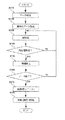
ここで、図13は、本実施例に係る三次元造形物の製造方法のフローチャートである。
Next, an example of a method for manufacturing a three-dimensional model using the forming
Here, FIG. 13 is a flowchart of a method for manufacturing a three-dimensional model according to the present embodiment.
図13で表されるように、本実施例の三次元造形物の製造方法においては、最初にステップS110で、三次元造形物のデータを取得する。詳細には、例えばパーソナルコンピューターにおいて実行されているアプリケーションプログラム等から、三次元造形物の形状を表すデータを取得する。 As shown in FIG. 13, in the method for manufacturing a three-dimensional model of the present embodiment, first, in step S110, data of the three-dimensional model is acquired. Specifically, for example, data representing the shape of a three-dimensional model is acquired from an application program executed on a personal computer.
次に、ステップS120で、層毎のデータを作成(生成)する。詳細には、三次元造形物の形状を表すデータにおいて、Z方向の造形解像度に従ってスライスし、断面毎にビットマップデータ(断面データ)を生成する。 Next, in step S120, data for each layer is created (generated). Specifically, in the data representing the shape of the three-dimensional modeled object, slices are made according to the modeling resolution in the Z direction, and bitmap data (cross-section data) is generated for each cross-section.
次に、ステップS130で、ステップS120で生成したデータに基づき、構成材料吐出部1230から構成材料を吐出して(なお、場合によっては、支持層形成用材料吐出部1730から支持層形成用材料も吐出して)、1層分の層(三次元造形物500の層)を形成する。
Next, in step S130, based on the data generated in step S120, the constituent material is discharged from the constituent material discharging unit 1230 (in some cases, the supporting layer forming material is also discharged from the supporting layer forming material discharging unit 1730). (Discharge) to form one layer (three-
次に、ステップS150で、電磁波照射部1000から電磁波(赤外線)を照射して、ステップS130で形成した三次元造形物500の層を加熱させることで、構成材料に含まれる溶媒を除去(揮発)させる。
なお、本実施例の三次元造形物の製造方法においては、電磁波照射部1000から電磁波を照射して溶媒を揮発させることで、三次元造形物500の層から溶媒を除去させるが、このような方法に限定されない。例えば、光やレーザーなどを三次元造形物500の層に照射して溶媒を除去させてもよいし、ホットプレートや他の加熱機構を用いて溶媒を除去させてもよいし、さらには、雰囲気を減圧させることや自然乾燥により溶媒を除去させてもよい。
Next, in step S150, the solvent contained in the constituent material is removed (volatile) by irradiating the electromagnetic wave (infrared ray) from the electromagnetic
In the method for manufacturing a three-dimensional model of the present embodiment, the solvent is removed from the layer of the three-
そして、ステップS160により、ステップS120において生成された各層に対応するビットマップデータに基づく三次元造形物500の積層物の造形が終了するまで、ステップS130からステップS160までが繰り返される。
Then, in step S160, steps S130 to S160 are repeated until the modeling of the laminate of the three-
ステップS130からステップS160までが繰り返されることでステップS120において生成された各層に対応するビットマップデータに基づく三次元造形物500の積層物の造形が終了すると、ステップS170で熱処理(所謂アニール)が行われる。
具体的には、例えば、不図示の恒温槽に三次元造形物500の積層物を移動し、該恒温槽において構成材料に含まれるバインダーのガラス転移温度(Tg)以上の温度であって軟化点以下の温度で該積層物を加熱する。なお、熱処理方法は、このような方法に限定されず、例えば、形成装置2000の内部に熱処理可能な加熱機構を備え形成装置2000の内部で熱処理を実行してもよく、また、加熱温度も上記のような温度範囲に限定されない。なお、恒温槽内部の雰囲気に関しての限定は特にないが、窒素雰囲気や、還元気体の雰囲気などを好ましく採用できる。
When the modeling of the laminate of the three-
Specifically, for example, a laminate of three-dimensional shaped
そして、ステップS180により、例えば上記の恒温槽において、上記ステップで形成した三次元造形物500の積層物を加熱して脱脂及び焼結の少なくともいずれかを実行する。
そして、ステップS180の終了に伴い、本実施例の三次元造形物の製造方法を終了する。
Then, in step S180, for example, in the above-mentioned constant temperature bath, the laminate of the three-
Then, with the end of step S180, the method for manufacturing the three-dimensional model of the present embodiment is completed.
上記のように、本実施例の三次元造形物の製造方法は、複数の層(層501、502、503、・・・50n)が積層されてなる三次元造形物500を製造する三次元造形物の製造方法であって、三次元造形物500を構成する粉末と、溶媒と、バインダーと、を含む組成物である構成材料(材料M)を用いて、前記層を形成する層形成工程(ステップS130)と、前記層に含まれる溶媒を除去する溶媒除去工程(ステップS150)と、層形成工程と溶媒除去工程とが実行されることで得られた複数の前記層からなる三次元造形物500の積層物に熱を加える熱処理工程(ステップS170)と、熱処理工程で熱処理された三次元造形物500の積層物に対して、脱脂及び焼結の少なくともいずれかを実行する加熱工程(ステップS180)と、を有する。
このように、本実施例の三次元造形物の製造方法は、脱脂及び焼結の少なくともいずれかを実行する加熱工程の前に、三次元造形物500の積層物(三次元造形物500を構成する層)に熱を加える熱処理工程を実行するため、溶媒除去工程で溶媒及びバインダーの分布が偏ったとしても、該熱処理工程によりその偏り(該偏りに伴う応力)を低減又は解消できる。したがって、本実施例の三次元造形物の製造方法は、脱脂や焼結を実行する前に三次元造形物500の積層物内での応力を低減又は解消でき、加熱工程(脱脂や焼結)に伴って三次元造形物500の積層物が変形することを抑制することができる。
なお、本実施例の三次元造形物の製造方法においては、ステップS170の熱処理工程において層形成工程と溶媒除去工程とが実行されることで得られた複数の前記層からなる三次元造形物500の積層物に熱を加えている。このため、熱処理工程の実行回数を減らすことができ、三次元造形物500の製造効率(製造速度)を高めることができる。しかしながら、ステップS170の熱処理工程において層形成工程と溶媒除去工程とが実行されることで得られた1層分の層に熱を加える方法(ステップS160とステップS170の順番を入れ替える)としてもよい。
As described above, the method for manufacturing a three-dimensional model of the present embodiment is a three-dimensional model for producing a three-
As described above, in the method for producing a three-dimensional model of the present embodiment, a laminate of the three-dimensional model 500 (constituting the three-
In the method for manufacturing the three-dimensional model of the present embodiment, the three-
また、本実施例の三次元造形物の製造方法では、熱処理工程において、バインダーのガラス転移温度以上の温度の熱を加えるので、溶媒除去工程でバインダーの分布が偏ったとしても、該熱処理工程によりその偏りを特に効果的に低減又は解消できる。したがって、本実施例の三次元造形物の製造方法は、脱脂や焼結を実行する前に三次元造形物500の積層物内での応力を特に効果的に低減又は解消でき、加熱工程(脱脂や焼結)に伴って三次元造形物の積層物が変形することを特に効果的に抑制することができる。
なお、熱処理工程において加える熱の温度は、バインダーのガラス転移温度+5℃の温度、或いは、バインダーのガラス転移温度+10℃の温度などが好ましく採用できる。
Further, in the method for producing a three-dimensional model of the present embodiment, heat is applied at a temperature equal to or higher than the glass transition temperature of the binder in the heat treatment step, so that even if the distribution of the binder is biased in the solvent removal step, the heat treatment step is performed. The bias can be reduced or eliminated particularly effectively. Therefore, the method for manufacturing the three-dimensional model of the present embodiment can particularly effectively reduce or eliminate the stress in the laminate of the three-
As the temperature of the heat applied in the heat treatment step, a temperature of the glass transition temperature of the binder + 5 ° C., a temperature of the glass transition temperature of the binder + 10 ° C., or the like can be preferably adopted.
さらに、本実施例の三次元造形物の製造方法では、前記熱処理工程において、バインダーの軟化点以下の温度の熱を加えるので、熱処理工程に伴ってバインダーが軟化して三次元造形物500の積層物が変形することを抑制できる。
Further, in the method for manufacturing a three-dimensional model of the present embodiment, heat at a temperature equal to or lower than the softening point of the binder is applied in the heat treatment step, so that the binder softens with the heat treatment step and the three-
ここで、構成材料には、各々複数種類の、三次元造形物を構成する粉末、溶剤、バインダーを含有させることができる。
そして、構成材料にバインダーが複数種類含まれていた場合、熱処理工程では、構成材料に含まれるバインダーのうちの最高のガラス転移温度以上の温度の熱を加えることができる。このような温度の熱を加えることで、バインダーが複数種類含まれていた場合でも、バインダーの分布の偏りを特に効果的に低減又は解消できる。
ただし、このような方法に限定されず、例えば、構成材料にバインダーが複数種類含まれていた場合、含有量が最大のバインダーのガラス転移温度以上の温度の熱を加える方法としてもよい。
Here, the constituent material may contain a plurality of types of powders, solvents, and binders constituting the three-dimensional model.
When a plurality of types of binders are contained in the constituent materials, heat at a temperature equal to or higher than the highest glass transition temperature among the binders contained in the constituent materials can be applied in the heat treatment step. By applying heat at such a temperature, even when a plurality of types of binders are contained, the bias in the distribution of the binders can be particularly effectively reduced or eliminated.
However, the method is not limited to such a method, and for example, when a plurality of types of binders are contained in the constituent material, a method of applying heat having a temperature equal to or higher than the glass transition temperature of the binder having the maximum content may be used.
また、本実施例の三次元造形物の製造方法では、溶媒除去工程は、層形成工程が1回行われる毎に実行される方法になっている。溶媒除去工程を1回行う毎に層形成工程が実行されるので、溶媒除去工程に伴うバインダーの分布の偏りを特に効果的に低減できる方法になっている。しかしながら、このような三次元造形物の製造方法に限定されない。 Further, in the method for manufacturing a three-dimensional model of the present embodiment, the solvent removing step is a method that is executed every time the layer forming step is performed. Since the layer forming step is executed every time the solvent removing step is performed, the method can particularly effectively reduce the bias of the binder distribution due to the solvent removing step. However, the method is not limited to the method for manufacturing such a three-dimensional model.
以下に、図13で表される三次元造形物の製造方法とは別の三次元造形物の製造方法(層形成工程が複数回行われてから溶媒除去工程が実行される三次元造形物の製造方法)について、図14を用いて説明する。
ここで、図14は、本実施例に係る三次元造形物の製造方法のフローチャートであって、図13で表される三次元造形物の製造方法に対してステップS130(層形成工程)とステップS150(溶媒除去工程)との間にステップS140(所定数の層が形成されたか否かを判断する工程)を実行する方法のフローチャートである。ステップS110からステップS130までとステップ150からステップS180までのフローは図13で表される上記三次元造形物の製造方法と同様なので、詳細な説明は省略する。
Below, a method for manufacturing a three-dimensional model different from the method for manufacturing the three-dimensional model shown in FIG. 13 (a three-dimensional model in which the solvent removing step is executed after the layer forming step is performed a plurality of times). The manufacturing method) will be described with reference to FIG.
Here, FIG. 14 is a flowchart of a three-dimensional model manufacturing method according to the present embodiment, and is a step S130 (layer forming step) and a step with respect to the three-dimensional model manufacturing method represented by FIG. It is a flowchart of the method of executing a step S140 (a step of determining whether or not a predetermined number of layers are formed) with S150 (a process of removing a solvent). Since the flow from step S110 to step S130 and from
本実施例の三次元造形物の製造方法は、ステップS130の層形成工程の終了後、ステップS150の溶媒除去工程に進むまでの間に、ステップS140で、所定数の層が形成されたか否かを判断する。すなわち、所定数の層が形成されるまで(所定の厚さの積層物となるまで)ステップS130を繰り返す。 In the method for producing a three-dimensional model of the present embodiment, whether or not a predetermined number of layers have been formed in step S140 after the layer forming step of step S130 is completed and before proceeding to the solvent removing step of step S150. To judge. That is, step S130 is repeated until a predetermined number of layers are formed (until a laminate having a predetermined thickness is obtained).
別の表現をすると、本実施例の三次元造形物の製造方法は、溶媒除去工程は、層形成工程が複数回行われてから実行される。このように、溶媒除去工程を複数回行ってから層形成工程を実行することで、溶媒除去工程の実行回数を減らすことができ、三次元造形物500の製造効率(製造速度)を高めることができる。
なお、ステップS140における所定数(溶媒除去工程が実行されるまでに行われる層形成工程の連続実行回数)は、三次元造形物500の積層物の形成が完成する数としてもよいが、そのような数に限定されず、2回以上であればよい。
In other words, in the method for producing a three-dimensional model of the present embodiment, the solvent removing step is executed after the layer forming step is performed a plurality of times. In this way, by executing the layer forming step after performing the solvent removing step a plurality of times, the number of executions of the solvent removing step can be reduced, and the manufacturing efficiency (manufacturing speed) of the three-
The predetermined number in step S140 (the number of consecutive executions of the layer forming step performed until the solvent removing step is executed) may be the number in which the formation of the laminate of the three-
本発明は、上述の実施例に限られるものではなく、その趣旨を逸脱しない範囲において種々の構成で実現することができる。例えば、発明の概要の欄に記載した各形態中の技術的特徴に対応する実施例中の技術的特徴は、上述の課題の一部又は全部を解決するために、あるいは、上述の効果の一部又は全部を達成するために、適宜、差し替えや、組み合わせを行うことが可能である。また、その技術的特徴が本明細書中に必須なものとして説明されていなければ、適宜、削除することが可能である。 The present invention is not limited to the above-described embodiment, and can be realized with various configurations within a range not deviating from the gist thereof. For example, the technical features in the examples corresponding to the technical features in each form described in the column of the outline of the invention are for solving a part or all of the above-mentioned problems, or one of the above-mentioned effects. It is possible to replace or combine as appropriate to achieve the part or all. Further, if the technical feature is not described as essential in the present specification, it can be appropriately deleted.
50、50a、50b、50c、50d…構成層構成部、110…基台、
111…駆動装置、120…ステージ、121…試料プレート、
130…ヘッドベース支持部、300…支持層、310…構成層、
400…制御ユニット、410…ステージコントローラー、
500…三次元造形物、501、502、503、・・・50n…層、
730…ヘッドベース支持部、1000…電磁波照射部、1100…ヘッドベース、
1200…構成材料供給装置、1210…構成材料供給ユニット、
1210a…構成材料収容部、1220…供給チューブ、1230…構成材料吐出部、
1230a…吐出ノズル、1230b…吐出駆動部、1400…ヘッドユニット、
1400a…保持治具、
1401、1402、1403及び1404…ヘッドユニット、
1500…材料供給コントローラー、1600…ヘッドベース、
1700…支持層形成用材料供給装置、1710…支持層形成用材料供給ユニット、
1710a…支持層形成用材料収容部、1720…供給チューブ、
1730…支持層形成用材料吐出部、1730a…吐出ノズル、
1730b…吐出駆動部、1900…ヘッドユニット、
1900a…保持治具、2000…形成装置(三次元造形物の製造装置)、
M…材料(構成材料、組成物)
50, 50a, 50b, 50c, 50d ... constituent layer constituent part, 110 ... base,
111 ... drive device, 120 ... stage, 121 ... sample plate,
130 ... head base support, 300 ... support layer, 310 ... constituent layer,
400 ... control unit, 410 ... stage controller,
500 ... 3D model, 501, 502, 503, ... 50n ... layer,
730 ... head base support, 1000 ... electromagnetic wave irradiation unit, 1100 ... head base,
1200 ... constituent material supply device, 1210 ... constituent material supply unit,
1210a ... Constituent material accommodating part, 1220 ... Supply tube, 1230 ... Constituent material discharge part,
1230a ... Discharge nozzle, 1230b ... Discharge drive unit, 1400 ... Head unit,
1400a ... Holding jig,
1401, 1402, 1403 and 1404 ... Head unit,
1500 ... Material supply controller, 1600 ... Head base,
1700 ... Support layer forming material supply device, 1710 ... Support layer forming material supply unit,
1710a ... Material accommodating portion for forming a support layer, 1720 ... Supply tube,
1730 ... Material discharge unit for forming a support layer, 1730a ... Discharge nozzle,
1730b ... Discharge drive unit, 1900 ... Head unit,
1900a ... Holding jig, 2000 ... Forming device (manufacturing device for three-dimensional model),
M ... Material (constituent material, composition)
Claims (1)
前記三次元造形物を構成する粉末と、溶媒と、バインダーと、を含む組成物を用いて、構成材料吐出部からペースト状の構成材料を液滴状または連続体形状で前記三次元造形物に対応する領域に吐出し、かつ、前記三次元造形物に対応する領域と隣接する領域に支持層形成用材料吐出部から前記構成材料を支持するペースト状の支持層形成用材料を液滴状または連続体形状で吐出することで、前記層を形成する層形成工程と、
前記層形成工程を繰り返し実行して、前記層が複数積層されてなる積層体を形成する積層工程と、
前記積層体に含まれる前記溶媒を除去する溶媒除去工程と、
前記溶媒除去工程が実行されることで得られた前記積層体に前記バインダーのガラス転移温度以上、かつ、前記バインダーの軟化点以下の温度の熱を加える熱処理工程と、
前記熱処理工程で熱処理された前記積層体に対して、脱脂及び焼結の少なくともいずれかを実行する加熱工程と、
を有し、
前記組成物に前記バインダーが複数種類含まれていた場合、前記熱処理工程は、前記バインダーのうちの最高のガラス転移温度以上の温度の熱を加えることを特徴とする三次元造形物の製造方法。 It is a manufacturing method of a three-dimensional model that manufactures a three-dimensional model in which a plurality of layers are laminated.
Using a composition containing the powder, solvent, and binder that make up the three-dimensional model, the paste-like constituent material can be made into the three-dimensional model in the form of droplets or a continuum from the component discharge section. A paste-like support layer-forming material that discharges to the corresponding region and supports the constituent material from the support layer-forming material discharge portion in the region adjacent to the region corresponding to the three-dimensional modeled object is droplet-shaped or A layer forming step of forming the layer by discharging in a continuous body shape, and
A laminating step of repeatedly executing the layer forming step to form a laminated body in which a plurality of the layers are laminated, and a laminating step.
A solvent removing step of removing the solvent contained in the laminate, and
A heat treatment step of applying heat to the laminate obtained by executing the solvent removing step at a temperature equal to or higher than the glass transition temperature of the binder and lower than the softening point of the binder.
A heating step of performing at least one of degreasing and sintering of the laminate heat-treated in the heat treatment step, and
Have a,
When a plurality of types of the binder are contained in the composition, the heat treatment step is a method for producing a three-dimensional molded product, which comprises applying heat having a temperature equal to or higher than the highest glass transition temperature among the binders.
Priority Applications (3)
| Application Number | Priority Date | Filing Date | Title |
|---|---|---|---|
| JP2017174985A JP6972811B2 (en) | 2017-09-12 | 2017-09-12 | Manufacturing method of 3D model |
| CN201811055231.7A CN109483879B (en) | 2017-09-12 | 2018-09-10 | Manufacturing method of three-dimensional shaped object |
| US16/127,752 US10994478B2 (en) | 2017-09-12 | 2018-09-11 | Method for producing three-dimensional shaped article |
Applications Claiming Priority (1)
| Application Number | Priority Date | Filing Date | Title |
|---|---|---|---|
| JP2017174985A JP6972811B2 (en) | 2017-09-12 | 2017-09-12 | Manufacturing method of 3D model |
Publications (2)
| Publication Number | Publication Date |
|---|---|
| JP2019052325A JP2019052325A (en) | 2019-04-04 |
| JP6972811B2 true JP6972811B2 (en) | 2021-11-24 |
Family
ID=65630384
Family Applications (1)
| Application Number | Title | Priority Date | Filing Date |
|---|---|---|---|
| JP2017174985A Active JP6972811B2 (en) | 2017-09-12 | 2017-09-12 | Manufacturing method of 3D model |
Country Status (3)
| Country | Link |
|---|---|
| US (1) | US10994478B2 (en) |
| JP (1) | JP6972811B2 (en) |
| CN (1) | CN109483879B (en) |
Families Citing this family (4)
| Publication number | Priority date | Publication date | Assignee | Title |
|---|---|---|---|---|
| JP7346917B2 (en) * | 2019-06-04 | 2023-09-20 | セイコーエプソン株式会社 | Manufacturing method for three-dimensional objects |
| JP7380080B2 (en) * | 2019-10-25 | 2023-11-15 | セイコーエプソン株式会社 | Method for manufacturing metal objects with porous structure |
| DE102020114471A1 (en) | 2020-05-29 | 2021-12-02 | Bayerische Motoren Werke Aktiengesellschaft | Process for the additive production of a molded body |
| JP7543755B2 (en) * | 2020-07-23 | 2024-09-03 | セイコーエプソン株式会社 | Machine Learning Equipment |
Family Cites Families (18)
| Publication number | Priority date | Publication date | Assignee | Title |
|---|---|---|---|---|
| US3953562A (en) * | 1974-07-15 | 1976-04-27 | International Business Machines Corporation | Process for the elimination of dimensional changes in ceramic green sheets |
| US4281420A (en) * | 1979-02-15 | 1981-08-04 | Raab S | Bone connective prostheses adapted to maximize strength and durability of prostheses-bone cement interface; and methods of forming same |
| US5382251A (en) * | 1989-01-31 | 1995-01-17 | Biomet, Inc. | Plug pulling method |
| US6220703B1 (en) * | 1999-12-29 | 2001-04-24 | Younger Manufacturing Co., Inc. | Ophthalmic lenses utilizing polyethylene terephthalate polarizing films |
| JP4438198B2 (en) | 2000-08-29 | 2010-03-24 | Jsr株式会社 | Post-processing method of stereolithography |
| US6471800B2 (en) * | 2000-11-29 | 2002-10-29 | Nanotek Instruments, Inc. | Layer-additive method and apparatus for freeform fabrication of 3-D objects |
| US6852272B2 (en) * | 2001-03-07 | 2005-02-08 | Advanced Ceramics Research, Inc. | Method for preparation of metallic and ceramic foam products and products made |
| US20020162642A1 (en) * | 2001-05-04 | 2002-11-07 | Walker Edward L. | Process for producing dental devices |
| US20060119017A1 (en) * | 2004-12-02 | 2006-06-08 | Hwa-Hsing Tang | Method for making ceramic work piece and cermet work piece |
| TWI482699B (en) * | 2012-05-21 | 2015-05-01 | Univ Nat Taipei Technology | A method for preparing inorganic green bodies with three - dimensional contours |
| EP3725497B1 (en) * | 2013-03-22 | 2024-07-03 | Markforged, Inc. | Three-dimensional printer |
| JP2015182424A (en) * | 2014-03-26 | 2015-10-22 | セイコーエプソン株式会社 | Three-dimensional structure manufacturing method, three-dimensional structure manufacturing apparatus, and three-dimensional structure |
| JP6536108B2 (en) * | 2015-03-19 | 2019-07-03 | 株式会社リコー | Composition liquid for three-dimensional modeling and three-dimensional modeling material set, and method and apparatus for manufacturing three-dimensional article |
| JP6569269B2 (en) * | 2015-03-30 | 2019-09-04 | 株式会社リコー | 3D modeling powder material, 3D modeling material set, 3D model manufacturing apparatus, and 3D model manufacturing method |
| KR102383504B1 (en) * | 2015-06-30 | 2022-04-06 | 엘에스오토모티브테크놀로지스 주식회사 | Regurating sound generating system for environment friendly vehicle and a method for controlling the system |
| JP6718132B2 (en) | 2015-11-06 | 2020-07-08 | セイコーエプソン株式会社 | Method and apparatus for manufacturing three-dimensional structure |
| JP6844225B2 (en) * | 2016-11-30 | 2021-03-17 | セイコーエプソン株式会社 | Manufacturing method of sintering powder and sintered body |
| CN110049838B (en) * | 2016-12-06 | 2022-06-07 | 马克弗巨德有限公司 | Method of additive manufacturing |
-
2017
- 2017-09-12 JP JP2017174985A patent/JP6972811B2/en active Active
-
2018
- 2018-09-10 CN CN201811055231.7A patent/CN109483879B/en active Active
- 2018-09-11 US US16/127,752 patent/US10994478B2/en active Active
Also Published As
| Publication number | Publication date |
|---|---|
| JP2019052325A (en) | 2019-04-04 |
| CN109483879B (en) | 2021-08-03 |
| CN109483879A (en) | 2019-03-19 |
| US10994478B2 (en) | 2021-05-04 |
| US20190077075A1 (en) | 2019-03-14 |
Similar Documents
| Publication | Publication Date | Title |
|---|---|---|
| JP6836101B2 (en) | Manufacturing method of 3D model | |
| US12103083B2 (en) | Three-dimensional shaped article production method | |
| JP6972811B2 (en) | Manufacturing method of 3D model | |
| JP6981558B2 (en) | 3D modeling stage, 3D modeling equipment and 3D modeling method | |
| US11745418B2 (en) | Method of manufacturing three-dimensionally formed object and three-dimensionally formed object manufacturing apparatus | |
| US20210154743A1 (en) | Method of manufacturing three-dimensionally formed object and three-dimensionally formed object manufacturing apparatus | |
| JP6826321B2 (en) | Modeling stage of 3D model, 3D model manufacturing device and 3D model manufacturing method | |
| JP6802517B2 (en) | Modeling stage of 3D model, 3D model manufacturing device and 3D model manufacturing method | |
| JP6950498B2 (en) | Manufacturing method of 3D model | |
| JP6924380B2 (en) | 3D model manufacturing equipment and 3D model manufacturing method | |
| JP6931205B2 (en) | Manufacturing method of 3D model | |
| JP6950780B2 (en) | Manufacturing method of 3D model | |
| JP2019099859A (en) | Method for manufacturing three-dimensional molded article |
Legal Events
| Date | Code | Title | Description |
|---|---|---|---|
| A621 | Written request for application examination |
Free format text: JAPANESE INTERMEDIATE CODE: A621 Effective date: 20200805 |
|
| A977 | Report on retrieval |
Free format text: JAPANESE INTERMEDIATE CODE: A971007 Effective date: 20210519 |
|
| A131 | Notification of reasons for refusal |
Free format text: JAPANESE INTERMEDIATE CODE: A131 Effective date: 20210526 |
|
| A521 | Request for written amendment filed |
Free format text: JAPANESE INTERMEDIATE CODE: A523 Effective date: 20210604 |
|
| A02 | Decision of refusal |
Free format text: JAPANESE INTERMEDIATE CODE: A02 Effective date: 20210812 |
|
| A521 | Request for written amendment filed |
Free format text: JAPANESE INTERMEDIATE CODE: A523 Effective date: 20210902 |
|
| C60 | Trial request (containing other claim documents, opposition documents) |
Free format text: JAPANESE INTERMEDIATE CODE: C60 Effective date: 20210902 |
|
| A911 | Transfer to examiner for re-examination before appeal (zenchi) |
Free format text: JAPANESE INTERMEDIATE CODE: A911 Effective date: 20210909 |
|
| C21 | Notice of transfer of a case for reconsideration by examiners before appeal proceedings |
Free format text: JAPANESE INTERMEDIATE CODE: C21 Effective date: 20210914 |
|
| TRDD | Decision of grant or rejection written | ||
| A01 | Written decision to grant a patent or to grant a registration (utility model) |
Free format text: JAPANESE INTERMEDIATE CODE: A01 Effective date: 20211005 |
|
| A61 | First payment of annual fees (during grant procedure) |
Free format text: JAPANESE INTERMEDIATE CODE: A61 Effective date: 20211018 |
|
| R150 | Certificate of patent or registration of utility model |
Ref document number: 6972811 Country of ref document: JP Free format text: JAPANESE INTERMEDIATE CODE: R150 |