JP6971563B2 - Manufacturing method of liquid supply unit and manufacturing method of liquid discharge head - Google Patents
Manufacturing method of liquid supply unit and manufacturing method of liquid discharge head Download PDFInfo
- Publication number
- JP6971563B2 JP6971563B2 JP2016228084A JP2016228084A JP6971563B2 JP 6971563 B2 JP6971563 B2 JP 6971563B2 JP 2016228084 A JP2016228084 A JP 2016228084A JP 2016228084 A JP2016228084 A JP 2016228084A JP 6971563 B2 JP6971563 B2 JP 6971563B2
- Authority
- JP
- Japan
- Prior art keywords
- flow path
- mold
- supply unit
- liquid supply
- joining
- Prior art date
- Legal status (The legal status is an assumption and is not a legal conclusion. Google has not performed a legal analysis and makes no representation as to the accuracy of the status listed.)
- Active
Links
- 239000007788 liquid Substances 0.000 title claims description 221
- 238000004519 manufacturing process Methods 0.000 title claims description 30
- 239000000758 substrate Substances 0.000 claims description 56
- 238000005304 joining Methods 0.000 claims description 49
- 239000000463 material Substances 0.000 claims description 36
- 239000011347 resin Substances 0.000 claims description 33
- 229920005989 resin Polymers 0.000 claims description 33
- 238000000465 moulding Methods 0.000 claims description 31
- 238000000034 method Methods 0.000 claims description 21
- 238000001746 injection moulding Methods 0.000 claims description 19
- 238000003466 welding Methods 0.000 claims description 17
- 239000000945 filler Substances 0.000 claims description 2
- 239000000976 ink Substances 0.000 description 118
- 238000011084 recovery Methods 0.000 description 55
- 238000004891 communication Methods 0.000 description 23
- 230000007246 mechanism Effects 0.000 description 16
- 230000008859 change Effects 0.000 description 13
- 238000010586 diagram Methods 0.000 description 5
- 239000000428 dust Substances 0.000 description 5
- 239000003566 sealing material Substances 0.000 description 5
- 230000000694 effects Effects 0.000 description 4
- 239000012778 molding material Substances 0.000 description 4
- 239000000123 paper Substances 0.000 description 3
- 230000008569 process Effects 0.000 description 3
- 238000001454 recorded image Methods 0.000 description 3
- 230000008719 thickening Effects 0.000 description 3
- 229920000106 Liquid crystal polymer Polymers 0.000 description 2
- 239000004977 Liquid-crystal polymers (LCPs) Substances 0.000 description 2
- VYPSYNLAJGMNEJ-UHFFFAOYSA-N Silicium dioxide Chemical compound O=[Si]=O VYPSYNLAJGMNEJ-UHFFFAOYSA-N 0.000 description 2
- 241000519995 Stachys sylvatica Species 0.000 description 2
- PNEYBMLMFCGWSK-UHFFFAOYSA-N aluminium oxide Inorganic materials [O-2].[O-2].[O-2].[Al+3].[Al+3] PNEYBMLMFCGWSK-UHFFFAOYSA-N 0.000 description 2
- 239000003086 colorant Substances 0.000 description 2
- 238000005260 corrosion Methods 0.000 description 2
- 230000007797 corrosion Effects 0.000 description 2
- 238000007599 discharging Methods 0.000 description 2
- 238000006073 displacement reaction Methods 0.000 description 2
- 238000009429 electrical wiring Methods 0.000 description 2
- 238000005187 foaming Methods 0.000 description 2
- 239000002184 metal Substances 0.000 description 2
- 238000005192 partition Methods 0.000 description 2
- 229920002492 poly(sulfone) Polymers 0.000 description 2
- 229920001955 polyphenylene ether Polymers 0.000 description 2
- 239000000126 substance Substances 0.000 description 2
- 238000011144 upstream manufacturing Methods 0.000 description 2
- XUIMIQQOPSSXEZ-UHFFFAOYSA-N Silicon Chemical compound [Si] XUIMIQQOPSSXEZ-UHFFFAOYSA-N 0.000 description 1
- UCKMPCXJQFINFW-UHFFFAOYSA-N Sulphide Chemical compound [S-2] UCKMPCXJQFINFW-UHFFFAOYSA-N 0.000 description 1
- 239000000853 adhesive Substances 0.000 description 1
- 230000001070 adhesive effect Effects 0.000 description 1
- 230000002411 adverse Effects 0.000 description 1
- 230000002238 attenuated effect Effects 0.000 description 1
- 238000009835 boiling Methods 0.000 description 1
- 238000006243 chemical reaction Methods 0.000 description 1
- 239000011248 coating agent Substances 0.000 description 1
- 238000000576 coating method Methods 0.000 description 1
- 239000002131 composite material Substances 0.000 description 1
- 230000006837 decompression Effects 0.000 description 1
- 238000001704 evaporation Methods 0.000 description 1
- 230000008020 evaporation Effects 0.000 description 1
- 239000000835 fiber Substances 0.000 description 1
- 239000010408 film Substances 0.000 description 1
- 239000010419 fine particle Substances 0.000 description 1
- 230000001771 impaired effect Effects 0.000 description 1
- 238000002347 injection Methods 0.000 description 1
- 239000007924 injection Substances 0.000 description 1
- 239000011256 inorganic filler Substances 0.000 description 1
- 229910003475 inorganic filler Inorganic materials 0.000 description 1
- 238000000206 photolithography Methods 0.000 description 1
- 229920003023 plastic Polymers 0.000 description 1
- 239000004033 plastic Substances 0.000 description 1
- 229920006389 polyphenyl polymer Polymers 0.000 description 1
- 229910052710 silicon Inorganic materials 0.000 description 1
- 239000010703 silicon Substances 0.000 description 1
- 239000000377 silicon dioxide Substances 0.000 description 1
- 238000011282 treatment Methods 0.000 description 1
- 239000002759 woven fabric Substances 0.000 description 1
Images


Classifications
-
- B—PERFORMING OPERATIONS; TRANSPORTING
- B29—WORKING OF PLASTICS; WORKING OF SUBSTANCES IN A PLASTIC STATE IN GENERAL
- B29C—SHAPING OR JOINING OF PLASTICS; SHAPING OF MATERIAL IN A PLASTIC STATE, NOT OTHERWISE PROVIDED FOR; AFTER-TREATMENT OF THE SHAPED PRODUCTS, e.g. REPAIRING
- B29C45/00—Injection moulding, i.e. forcing the required volume of moulding material through a nozzle into a closed mould; Apparatus therefor
- B29C45/0053—Injection moulding, i.e. forcing the required volume of moulding material through a nozzle into a closed mould; Apparatus therefor combined with a final operation, e.g. shaping
- B29C45/006—Joining parts moulded in separate cavities
-
- B—PERFORMING OPERATIONS; TRANSPORTING
- B29—WORKING OF PLASTICS; WORKING OF SUBSTANCES IN A PLASTIC STATE IN GENERAL
- B29C—SHAPING OR JOINING OF PLASTICS; SHAPING OF MATERIAL IN A PLASTIC STATE, NOT OTHERWISE PROVIDED FOR; AFTER-TREATMENT OF THE SHAPED PRODUCTS, e.g. REPAIRING
- B29C65/00—Joining or sealing of preformed parts, e.g. welding of plastics materials; Apparatus therefor
- B29C65/02—Joining or sealing of preformed parts, e.g. welding of plastics materials; Apparatus therefor by heating, with or without pressure
-
- B—PERFORMING OPERATIONS; TRANSPORTING
- B41—PRINTING; LINING MACHINES; TYPEWRITERS; STAMPS
- B41J—TYPEWRITERS; SELECTIVE PRINTING MECHANISMS, i.e. MECHANISMS PRINTING OTHERWISE THAN FROM A FORME; CORRECTION OF TYPOGRAPHICAL ERRORS
- B41J2/00—Typewriters or selective printing mechanisms characterised by the printing or marking process for which they are designed
- B41J2/005—Typewriters or selective printing mechanisms characterised by the printing or marking process for which they are designed characterised by bringing liquid or particles selectively into contact with a printing material
- B41J2/01—Ink jet
- B41J2/135—Nozzles
- B41J2/14—Structure thereof only for on-demand ink jet heads
- B41J2/14016—Structure of bubble jet print heads
- B41J2/14024—Assembling head parts
-
- B—PERFORMING OPERATIONS; TRANSPORTING
- B41—PRINTING; LINING MACHINES; TYPEWRITERS; STAMPS
- B41J—TYPEWRITERS; SELECTIVE PRINTING MECHANISMS, i.e. MECHANISMS PRINTING OTHERWISE THAN FROM A FORME; CORRECTION OF TYPOGRAPHICAL ERRORS
- B41J2/00—Typewriters or selective printing mechanisms characterised by the printing or marking process for which they are designed
- B41J2/005—Typewriters or selective printing mechanisms characterised by the printing or marking process for which they are designed characterised by bringing liquid or particles selectively into contact with a printing material
- B41J2/01—Ink jet
- B41J2/135—Nozzles
- B41J2/14—Structure thereof only for on-demand ink jet heads
- B41J2/14016—Structure of bubble jet print heads
- B41J2/14032—Structure of the pressure chamber
- B41J2/1404—Geometrical characteristics
-
- B—PERFORMING OPERATIONS; TRANSPORTING
- B41—PRINTING; LINING MACHINES; TYPEWRITERS; STAMPS
- B41J—TYPEWRITERS; SELECTIVE PRINTING MECHANISMS, i.e. MECHANISMS PRINTING OTHERWISE THAN FROM A FORME; CORRECTION OF TYPOGRAPHICAL ERRORS
- B41J2/00—Typewriters or selective printing mechanisms characterised by the printing or marking process for which they are designed
- B41J2/005—Typewriters or selective printing mechanisms characterised by the printing or marking process for which they are designed characterised by bringing liquid or particles selectively into contact with a printing material
- B41J2/01—Ink jet
- B41J2/135—Nozzles
- B41J2/14—Structure thereof only for on-demand ink jet heads
- B41J2/14016—Structure of bubble jet print heads
- B41J2/14072—Electrical connections, e.g. details on electrodes, connecting the chip to the outside...
-
- B—PERFORMING OPERATIONS; TRANSPORTING
- B41—PRINTING; LINING MACHINES; TYPEWRITERS; STAMPS
- B41J—TYPEWRITERS; SELECTIVE PRINTING MECHANISMS, i.e. MECHANISMS PRINTING OTHERWISE THAN FROM A FORME; CORRECTION OF TYPOGRAPHICAL ERRORS
- B41J2/00—Typewriters or selective printing mechanisms characterised by the printing or marking process for which they are designed
- B41J2/005—Typewriters or selective printing mechanisms characterised by the printing or marking process for which they are designed characterised by bringing liquid or particles selectively into contact with a printing material
- B41J2/01—Ink jet
- B41J2/135—Nozzles
- B41J2/16—Production of nozzles
- B41J2/1601—Production of bubble jet print heads
- B41J2/1603—Production of bubble jet print heads of the front shooter type
-
- B—PERFORMING OPERATIONS; TRANSPORTING
- B41—PRINTING; LINING MACHINES; TYPEWRITERS; STAMPS
- B41J—TYPEWRITERS; SELECTIVE PRINTING MECHANISMS, i.e. MECHANISMS PRINTING OTHERWISE THAN FROM A FORME; CORRECTION OF TYPOGRAPHICAL ERRORS
- B41J2/00—Typewriters or selective printing mechanisms characterised by the printing or marking process for which they are designed
- B41J2/005—Typewriters or selective printing mechanisms characterised by the printing or marking process for which they are designed characterised by bringing liquid or particles selectively into contact with a printing material
- B41J2/01—Ink jet
- B41J2/135—Nozzles
- B41J2/16—Production of nozzles
- B41J2/1621—Manufacturing processes
- B41J2/1623—Manufacturing processes bonding and adhesion
-
- B—PERFORMING OPERATIONS; TRANSPORTING
- B41—PRINTING; LINING MACHINES; TYPEWRITERS; STAMPS
- B41J—TYPEWRITERS; SELECTIVE PRINTING MECHANISMS, i.e. MECHANISMS PRINTING OTHERWISE THAN FROM A FORME; CORRECTION OF TYPOGRAPHICAL ERRORS
- B41J2/00—Typewriters or selective printing mechanisms characterised by the printing or marking process for which they are designed
- B41J2/005—Typewriters or selective printing mechanisms characterised by the printing or marking process for which they are designed characterised by bringing liquid or particles selectively into contact with a printing material
- B41J2/01—Ink jet
- B41J2/135—Nozzles
- B41J2/16—Production of nozzles
- B41J2/1621—Manufacturing processes
- B41J2/1637—Manufacturing processes molding
-
- B—PERFORMING OPERATIONS; TRANSPORTING
- B41—PRINTING; LINING MACHINES; TYPEWRITERS; STAMPS
- B41J—TYPEWRITERS; SELECTIVE PRINTING MECHANISMS, i.e. MECHANISMS PRINTING OTHERWISE THAN FROM A FORME; CORRECTION OF TYPOGRAPHICAL ERRORS
- B41J2/00—Typewriters or selective printing mechanisms characterised by the printing or marking process for which they are designed
- B41J2/005—Typewriters or selective printing mechanisms characterised by the printing or marking process for which they are designed characterised by bringing liquid or particles selectively into contact with a printing material
- B41J2/01—Ink jet
- B41J2/135—Nozzles
- B41J2/16—Production of nozzles
- B41J2/1648—Production of print heads with thermal bend detached actuators
-
- B—PERFORMING OPERATIONS; TRANSPORTING
- B29—WORKING OF PLASTICS; WORKING OF SUBSTANCES IN A PLASTIC STATE IN GENERAL
- B29C—SHAPING OR JOINING OF PLASTICS; SHAPING OF MATERIAL IN A PLASTIC STATE, NOT OTHERWISE PROVIDED FOR; AFTER-TREATMENT OF THE SHAPED PRODUCTS, e.g. REPAIRING
- B29C45/00—Injection moulding, i.e. forcing the required volume of moulding material through a nozzle into a closed mould; Apparatus therefor
- B29C45/0053—Injection moulding, i.e. forcing the required volume of moulding material through a nozzle into a closed mould; Apparatus therefor combined with a final operation, e.g. shaping
- B29C45/006—Joining parts moulded in separate cavities
- B29C2045/0063—Joining parts moulded in separate cavities facing before assembling, i.e. bringing the parts opposite to each other before assembling
-
- B—PERFORMING OPERATIONS; TRANSPORTING
- B29—WORKING OF PLASTICS; WORKING OF SUBSTANCES IN A PLASTIC STATE IN GENERAL
- B29K—INDEXING SCHEME ASSOCIATED WITH SUBCLASSES B29B, B29C OR B29D, RELATING TO MOULDING MATERIALS OR TO MATERIALS FOR MOULDS, REINFORCEMENTS, FILLERS OR PREFORMED PARTS, e.g. INSERTS
- B29K2081/00—Use of polymers having sulfur, with or without nitrogen, oxygen or carbon only, in the main chain, as moulding material
- B29K2081/04—Polysulfides, e.g. PPS, i.e. polyphenylene sulfide or derivatives thereof
-
- B—PERFORMING OPERATIONS; TRANSPORTING
- B29—WORKING OF PLASTICS; WORKING OF SUBSTANCES IN A PLASTIC STATE IN GENERAL
- B29K—INDEXING SCHEME ASSOCIATED WITH SUBCLASSES B29B, B29C OR B29D, RELATING TO MOULDING MATERIALS OR TO MATERIALS FOR MOULDS, REINFORCEMENTS, FILLERS OR PREFORMED PARTS, e.g. INSERTS
- B29K2105/00—Condition, form or state of moulded material or of the material to be shaped
- B29K2105/0079—Liquid crystals
-
- B—PERFORMING OPERATIONS; TRANSPORTING
- B29—WORKING OF PLASTICS; WORKING OF SUBSTANCES IN A PLASTIC STATE IN GENERAL
- B29K—INDEXING SCHEME ASSOCIATED WITH SUBCLASSES B29B, B29C OR B29D, RELATING TO MOULDING MATERIALS OR TO MATERIALS FOR MOULDS, REINFORCEMENTS, FILLERS OR PREFORMED PARTS, e.g. INSERTS
- B29K2105/00—Condition, form or state of moulded material or of the material to be shaped
- B29K2105/06—Condition, form or state of moulded material or of the material to be shaped containing reinforcements, fillers or inserts
- B29K2105/16—Fillers
-
- B—PERFORMING OPERATIONS; TRANSPORTING
- B29—WORKING OF PLASTICS; WORKING OF SUBSTANCES IN A PLASTIC STATE IN GENERAL
- B29L—INDEXING SCHEME ASSOCIATED WITH SUBCLASS B29C, RELATING TO PARTICULAR ARTICLES
- B29L2031/00—Other particular articles
- B29L2031/767—Printing equipment or accessories therefor
- B29L2031/7678—Ink or toner cartridges
-
- B—PERFORMING OPERATIONS; TRANSPORTING
- B41—PRINTING; LINING MACHINES; TYPEWRITERS; STAMPS
- B41J—TYPEWRITERS; SELECTIVE PRINTING MECHANISMS, i.e. MECHANISMS PRINTING OTHERWISE THAN FROM A FORME; CORRECTION OF TYPOGRAPHICAL ERRORS
- B41J2/00—Typewriters or selective printing mechanisms characterised by the printing or marking process for which they are designed
- B41J2/005—Typewriters or selective printing mechanisms characterised by the printing or marking process for which they are designed characterised by bringing liquid or particles selectively into contact with a printing material
- B41J2/01—Ink jet
- B41J2/135—Nozzles
- B41J2/14—Structure thereof only for on-demand ink jet heads
- B41J2002/14467—Multiple feed channels per ink chamber
-
- B—PERFORMING OPERATIONS; TRANSPORTING
- B41—PRINTING; LINING MACHINES; TYPEWRITERS; STAMPS
- B41J—TYPEWRITERS; SELECTIVE PRINTING MECHANISMS, i.e. MECHANISMS PRINTING OTHERWISE THAN FROM A FORME; CORRECTION OF TYPOGRAPHICAL ERRORS
- B41J2202/00—Embodiments of or processes related to ink-jet or thermal heads
- B41J2202/01—Embodiments of or processes related to ink-jet heads
- B41J2202/12—Embodiments of or processes related to ink-jet heads with ink circulating through the whole print head
-
- B—PERFORMING OPERATIONS; TRANSPORTING
- B41—PRINTING; LINING MACHINES; TYPEWRITERS; STAMPS
- B41J—TYPEWRITERS; SELECTIVE PRINTING MECHANISMS, i.e. MECHANISMS PRINTING OTHERWISE THAN FROM A FORME; CORRECTION OF TYPOGRAPHICAL ERRORS
- B41J2202/00—Embodiments of or processes related to ink-jet or thermal heads
- B41J2202/01—Embodiments of or processes related to ink-jet heads
- B41J2202/19—Assembling head units
-
- B—PERFORMING OPERATIONS; TRANSPORTING
- B41—PRINTING; LINING MACHINES; TYPEWRITERS; STAMPS
- B41J—TYPEWRITERS; SELECTIVE PRINTING MECHANISMS, i.e. MECHANISMS PRINTING OTHERWISE THAN FROM A FORME; CORRECTION OF TYPOGRAPHICAL ERRORS
- B41J2202/00—Embodiments of or processes related to ink-jet or thermal heads
- B41J2202/01—Embodiments of or processes related to ink-jet heads
- B41J2202/20—Modules
Landscapes
- Engineering & Computer Science (AREA)
- Manufacturing & Machinery (AREA)
- Mechanical Engineering (AREA)
- Physics & Mathematics (AREA)
- Geometry (AREA)
- Particle Formation And Scattering Control In Inkjet Printers (AREA)
Description
本発明は、インク等の液体を供給するための液体供給ユニットの製造方法、およびインク等の液体を吐出可能な液体吐出ヘッドの製造方法に関するものである。 The present invention relates to a method for manufacturing a liquid supply unit for supplying a liquid such as ink, and a method for manufacturing a liquid ejection head capable of ejecting a liquid such as ink.
特許文献1には、いわゆるシリアル型の液体吐出ヘッドが記載されており、この液体吐出ヘッドは、記録素子基板、流路プレート、インクタンクを搭載するタンクホルダー、流路形成部材、およびフィルタなどから構成されている。流路プレート、流路形成部材、およびフィルタは、液体吐出ヘッドに液体を供給するための液体供給ユニットとして機能する。流路プレートは接着等によってタンクホルダーに結合され、流路形成部材は超音波溶着によってホルダーに結合される。フィルタは、インクタンクとホルダーとの間に配されて、外部からの塵埃の侵入を防止する。
特許文献1に記載の比較的短い液体吐出ヘッドをライン型の長尺な液体吐出ヘッドに適用する場合には、液体吐出ヘッドの長さに対応する長尺な流路形成部材が必要となる。このような長尺な流路形成部材を樹脂の射出成形によって作製する場合には、金型から離型した際の流路形成部材の硬化収縮、ねじれ、および反りなどによって、その流路形成部材に大きな形状変化が生じるおそれがある。また、液体供給ユニットを作製する際には、流路形成部材に形成された流路から液体が漏れないように、流路形成部材に蓋部材などを接合する必要がある。しかし、形状変化が生じた長尺な流路形成部材に対して、流路から液体が漏れないように蓋部材などを接合することは困難である。また、流路抵抗を抑制するためにフィルタの面積を拡大した場合には、形状変化が生じた長尺な流路形成部材に対して、そのようなフィルタを接合することも困難となる。
When the relatively short liquid discharge head described in
本発明の目的は、液体供給ユニットを構成する部材の射出成形後、その部材の形状変化を抑制しつつ、その部材に、液体供給ユニットを構成する他の部材を接合することができる液体供給ユニットおよび液体吐出ヘッドの製造方法を提供することにある。 An object of the present invention is a liquid supply unit capable of joining another member constituting the liquid supply unit to the member while suppressing a change in the shape of the member after injection molding of the member constituting the liquid supply unit. And to provide a method of manufacturing a liquid discharge head.
本発明の液体供給ユニットの製造方法は、液体吐出ヘッドに液体を供給するための液体流路を形成する長手形状を有する液体供給ユニットの製造方法であって、開閉可能な第1および第2金型を含む射出成形用金型によって、前記液体供給ユニットを構成する長手形状の第1および第2部材のうちの少なくとも前記第1部材を射出成形する成形工程と、前記成形工程にて射出成形された前記第1部材を前記第1金型に残したまま、前記第1および第2金型を開く型開き工程と、前記第1金型に残された前記第1部材に、前記液体供給ユニットを構成するフィルタを溶着接合する第1接合工程と、前記第1および第2金型を閉じて、前記フィルタが溶着接合されかつ前記第1金型に残された前記第1部材と、前記第2金型に残された前記第2部材とを接合する第2接合工程と、を含み、前記成形工程において、前記第1部材の長手方向における中心に対して前記長手方向の一端側に位置する第1のゲート位置、及び前記一端側と反対側の他端側に位置する第2のゲート位置から樹脂を前記第1金型内に射出して前記第1部材を成形し、前記第2接合工程において、前記第1部材の前記中心に対して前記第1のゲート位置よりも前記一端側に位置する第3のゲート位置、及び前記第2のゲート位置よりも前記他端側に位置する第4のゲート位置から樹脂を射出して前記第1部材と前記第2部材とを接合する、ことを特徴とする。The method for manufacturing a liquid supply unit of the present invention is a method for manufacturing a liquid supply unit having a longitudinal shape forming a liquid flow path for supplying liquid to a liquid discharge head, and is a method for manufacturing a first and second metal that can be opened and closed. An injection molding die including a mold is used for injection molding in a molding step of injection molding at least the first member of the first and second members having a longitudinal shape constituting the liquid supply unit, and an injection molding in the molding step. The liquid supply unit is used in the mold opening step of opening the first and second molds while leaving the first member in the first mold, and in the first member left in the first mold. The first joining step of welding and joining the filters constituting the above, the first member which is welded and joined by closing the first and second molds and left in the first mold, and the first member. 2 A second joining step of joining the second member left in the mold is included, and in the molding step, the first member is located on one end side in the longitudinal direction with respect to the center in the longitudinal direction. The resin is injected into the first mold from the first gate position and the second gate position located on the other end side opposite to the one end side to form the first member, and the second joining is performed. In the step, a third gate position located on the one end side of the first gate position with respect to the center of the first member, and a second gate position located on the other end side of the second gate position. It is characterized in that a resin is injected from the gate position of No. 4 to join the first member and the second member.
本発明によれば、液体供給ユニットを構成する部材の射出成形後、その部材を金型に残して形状変化を抑制したまま、その部材に、液体供給ユニットを構成する他の部材を接合することができる。 According to the present invention, after injection molding of a member constituting a liquid supply unit, another member constituting the liquid supply unit is joined to the member while the member is left in a mold and the shape change is suppressed. Can be done.
以下、本発明の実施形態を図面に基づいて説明する。 Hereinafter, embodiments of the present invention will be described with reference to the drawings.
(第1の実施形態)
図1から図14は、本発明の第1の実施形態を説明するための図である。本実施形態の液体吐出装置は、液体吐出ヘッドとしてのインクジェット記録ヘッドから、液体としてのインクを吐出して画像を記録するインクジェット記録装置としての適用例である。
(First Embodiment)
1 to 14 are diagrams for explaining the first embodiment of the present invention. The liquid ejection device of the present embodiment is an application example as an inkjet recording apparatus that ejects ink as a liquid from an inkjet recording head as a liquid ejection head and records an image.
(液体吐出装置の構成例)
図1は、本例のインクジェット記録装置1000(以下、「記録装置」とも称す)の概略構成図である。記録装置1000は記録媒体2を矢印Yの搬送方向に搬送する搬送部1、記録媒体2の搬送方向と交差(本例の場合は、直交)する方向に延在するように配置されるライン型の液体吐出ヘッド3と、を備える。本例の記録装置1000は、記録媒体2を連続的もしくは間欠的に搬送しながら、記録媒体2に画像を連続的に記録するライン型記録装置である。記録媒体2はカット紙に限らず、連続したロール紙であってもよい。液体吐出ヘッド3は、シアン(C)、マゼンタ(M)、イエロー(Y)、ブラック(K)のインクを吐出することによって、フルカラーの画像の記録が可能である。液体吐出ヘッド3には、それらのインクを液体吐出ヘッド3へ供給するための供給路、メインタンク、およびバッファタンクが接続される。また、液体吐出ヘッド3には、液体吐出ヘッド3へ電力およびインクの吐出制御信号を伝送するための電気制御部が接続される。液体吐出ヘッド3内におけるインクおよび電気信号の経路については後述する。
(Configuration example of liquid discharge device)
FIG. 1 is a schematic configuration diagram of the inkjet recording apparatus 1000 (hereinafter, also referred to as “recording apparatus”) of this example. The
(インクの循環経路)
図2は、記録装置1000に適用可能なインクの循環経路の説明図である。液体吐出ヘッド3は、第1循環ポンプ(P3)1002およびバッファタンク1003等に流体的に接続されている。図2においては、説明を簡略化するために、CMYKインクの内の一色のインクの循環経路のみを示す。実際には、それら4色分のインクの循環経路と、それらの対応する液体吐出ヘッド3と、が記録装置本体に備えられている。メインタンク1006に接続されるサブタンクとしてのバッファタンク1003は、その内部と外部とを連通する大気連通口(不図示)を有し、その大気連通口によって、インク中の気泡を外部に排出可能である。バッファタンク1003に接続される補充ポンプ1005は、液体吐出ヘッド3によって消費された分のインクをメインタンク1006からバッファタンク1003へ補充する。インクは、記録時における液体吐出ヘッド3からの吐出、およびインクの吐出状態を良好に位置するための回復処理(吸引回復および予備吐出など)時に排出されることによって、消費される。
(Ink circulation path)
FIG. 2 is an explanatory diagram of an ink circulation path applicable to the
第1循環ポンプ1002は、流出口301cおよび液体接続部111bを介して、液体吐出ヘッド3内のインクを吸引してバッファタンク1003へ送る。第1循環ポンプ1002としては、定量的な送液能力を有する容積型ポンプが好ましい。具体的には、チューブポンプ、ギアポンプ、ダイヤフラムポンプ、およびシリンジポンプ等が挙げられる。例えば、一般的な定流量弁またはリリーフ弁がポンプ出口に配されて、一定流量を確保する形態のポンプを用いることができる。液体吐出ヘッド3の駆動時には、第1循環ポンプ1002によって、共通回収流路212内を一定量のインクが矢印A方向に流される。その流量は、記録画像の画質に影響しない程度に、液体吐出ヘッド3における各記録素子基板10の相互間の温度差を抑える量に設定することが好ましい。その流量が大き過ぎた場合には、液体吐出ユニット300内の流路の圧損の影響により、各記録素子基板10におけるインクの負圧差が大きくなり過ぎて、画像に濃度ムラが生じるおそれがある。そのため、各記録素子基板10の相互間における温度差と負圧差を考慮して、流量を設定することが好ましい。
The
負圧制御ユニット230は、第2循環ポンプ(P)1004と液体吐出ユニット300との間の流路に設けられている。負圧制御ユニット230は、画像の記録デューティーに応じてインクの循環系における流量が変動した場合でも、負圧制御ユニット230よりも下流側(液体吐出ユニット300側)のインクの圧力を、予め設定した一定圧力に維持する機能を有する。負圧制御ユニット230を構成する2つの圧力調整機構230a,230bは、それらよりも下流側の圧力を、所望の設定圧を中心とする一定の範囲内に制御できるものであれば、どのような機構であってよい。一例として、いわゆる「減圧レギュレーター」と同様の機構を採用することができる。減圧レギュレーターを用いた場合には、図2のように、第2循環ポンプ1004によって、液体供給ユニット220を介して負圧制御ユニット230の上流側を加圧することが好ましい。これにより、バッファタンク1003が液体吐出ヘッド3に及ぼす水頭圧の影響を抑制して、記録装置1000におけるバッファタンク1003のレイアウトの自由度を高めることができる。第2循環ポンプ1004は、液体吐出ヘッド3の駆動時におけるインクの循環流量の範囲内において、一定圧以上の揚程圧を有するものであればよく、ターボ型ポンプおよび容積型ポンプなどが使用できる。具体的には、ダイヤフラムポンプ等が適用可能である。また、第2循環ポンプ1004の代わりに、例えば、負圧制御ユニット230に対してある一定の水頭差をもって配置された水頭タンクが適用可能である。負圧制御ユニット230には、第2循環ポンプ1004からのインクが液体接続部111aおよびフィルタ221を通して導入される。
The negative
図2における負圧制御ユニット230は、設定圧が互いに異なる2つの圧力調整機構230a,230bを備える。設定圧が相対的に高い圧力調整機構(H)230aは、液体供給ユニット220内の液体流路および流入口301aを介して、液体吐出ユニット300内の共通供給流路211(211(1),211(2))に接続されている。また、設定圧が相対的に低い圧力調整機構(L)230bは、液体供給ユニット220内の流路および流入口301bを介して、液体吐出ユニット300内の共通回収流路212に接続されている。液体吐出ユニット300には、共通供給流路211、共通回収流路212、個別供給流路213、および個別回収流路214が形成されている。個別供給流路213は、各記録素子基板10内の複数の圧力室に個別に連通し、個別回収流路214は、各記録素子基板10内の複数の圧力室に個別に連通する。個別供給流路213は共通供給流路211に連通し、個別回収流路214は共通回収流路212に連通する。共通供給流路211内のインクは、圧力調整機構230aによって比較的高圧に制御され、共通回収流路212内のインクは、圧力調整機構230bによって比較的低圧に制御される。このように、共通供給流路211と共通回収流路212との間に所定の圧力差が設定され、共通回収流路212内のインクが第1循環ポンプ1002によって吸引される。これらの結果、共通供給流路211内のインクは、個別供給流路213および個別回収流路214を介して、記録素子基板10の複数の圧力室内を矢印B方向に通過して共通回収流路212へ流れる。
The negative
このように、液体吐出ユニット300においては、共通供給流路211から各記録素子基板10の圧力室内を通過して共通回収流路212に回収されるインクの流れと、共通回収流路212内を矢印A方向に通過するインクの流れと、が発生する。個別供給流路213および個別回収流路214介して、共通供給流路211から共通回収流路212へ流れるインクによって、各記録素子基板10において発生する熱を外部へ排出することができる。また、液体吐出ヘッド3による記録動作時に、インクを吐出しない圧力室にもインクの流れを生じさせることができるため、その圧力室に対応するインクの吐出口におけるインクの増粘を抑制することができる。また、増粘したインクおよびインク中の異物は、共通回収流路212を通して外部へ排出することができる。これらの結果、本例の液体吐出ヘッド3は、高画質な画像を高速に記録することが可能となる。
As described above, in the
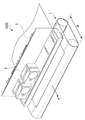
(液体吐出ヘッド構成)
図3(a),(b)は、本実施形態における液体吐出ヘッド3の斜視図である。本例の液体吐出ヘッド3は、記録素子基板10が直線上に15個配列(インラインに配置)されるライン型の液体吐出ヘッドであり、1つの記録素子基板10においてCMYKの4色のインクが吐出可能である。負圧制御ユニット230は、それらの4色のインクのそれぞれに対応するように計4つ配備されている。図3(a)のように、液体吐出ヘッド3における各記録素子基板10は、フレキシブル配線基板40および電気配線基板90を介して、信号入力端子91と電力供給端子92に電気的に接続される。信号入力端子91および電力供給端子92は、記録装置1000の制御部に電気的に接続され、それぞれ、インクを吐出されるための吐出駆動信号、およびインクの吐出に必要な電力を記録素子基板10に供給する。電気配線基板90内の電気回路によって配線を集約することにより、信号出力端子91および電力供給端子92の数を記録素子基板10の数に比べて少なくすることができる。そのため、記録装置1000に対して液体吐出ヘッド3を組み付ける時、および液体吐出ヘッドの交換時に、取り外しが必要な電気接続部の数を少なくすることができる。液体接続部111a,111bは、CMYKの4色のインクのそれぞれに対応するように4つずつ配備されており、図2のように、それぞれのインク色に対応する記録装置1000の液体供給系に接続される。これにより、CMYKの4色のインクが記録装置1000の供給系から液体吐出ヘッド3に供給され、また液体吐出ヘッド3内を通過したインクが記録装置1000の供給系へ回収される。このように、各色のインクは、記録装置1000の流路と、液体吐出ヘッド3の流路と、を介して循環される。
(Liquid discharge head configuration)
3 (a) and 3 (b) are perspective views of the
図4は、液体吐出ヘッド3の分解斜視図であり、液体吐出ユニット300、液体供給ユニット220、および電気配線基板90は筺体80に取り付けられている。液体供給ユニット220には、インク色毎に対応する液体接続部111a,111b(図3(b)参照)が設けられている。また、液体供給ユニット220の内部には、各色のインク中の異物を取り除くために、各色のインクに対応する液体接続部111aのそれぞれに連通するインク色毎のフィルタ221(図2参照)が備えられている。フィルタ221を通過したインクは、インク色毎の負圧制御ユニット230へ供給される。負圧制御ユニット230は圧力調整弁からなるユニットであり、その内部の弁およびバネ部材などによってインクの圧力を調整する。すなわち、インクの流量の変動に伴って生じる記録装置1000の供給系(液体吐出ヘッド3の上流側の供給系)内の圧損変化を大幅に減衰させて、負圧制御ユニット230よりも下流側(液体吐出ユニット300側)の負圧をある一定範囲内に安定させる。負圧制御ユニット230内には、図2のように2つの圧力調整機構230a,230bが内蔵されている。高圧側の圧力調整機構230aが液体吐出ユニット300内の共通供給流路211に接続され、低圧側の圧力調整機構230bが共通回収流路212に接続されている。
FIG. 4 is an exploded perspective view of the
筐体80は、液体吐出ユニット用の支持部81と電気配線基板用の支持部82とを含み、液体吐出ユニット300と電気配線基板90を支持すると共に、液体吐出ヘッド3の剛性を確保する。支持部82には、電気配線基板90がネジによって固定される。支持部81には、ジョイントゴム100が挿入される開口83,84,85,86が設けられている。液体供給ユニット220から供給されるインクは、ジョイントゴム100を介して、液体吐出ユニット300を構成する第3流路部材70へ導入される。
The
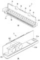
液体吐出ユニット300は、複数の吐出モジュール200と、流路部材210と、を含む。液体吐出ユニット300における記録媒体2側の面には、カバー部材130が取り付けられる。カバー部材130は、長尺の開口131が形成された額縁状の部材であり、開口131からは、吐出モジュール200に含まれる記録素子基板10および封止材110(図8)が露出する。開口131の周囲の枠部は、記録待機時に、液体吐出ヘッド3をキャップするキャップ部材が当接する当接面として機能する。その開口131の周囲に沿って接着剤、封止材、および充填材等を塗布して、液体吐出ユニット300の吐出口面(インク吐出口の形成面)上の凹凸および隙間を埋めることにより、キャップ時に閉空間が形成されるようにすることが好ましい。
The
流路部材210は、第1流路部材50、第2流路部材60、および第3流路部材70を積層した構成である。流路部材210は、液体供給ユニット220から供給されたインクを各吐出モジュール200へ分配し、また吐出モジュール200から環流するインクを液体供給ユニット220へと戻す。この流路部材210は、液体吐出ユニット支持部81にネジによって固定される。
The
図5(a)から(f)は、第1,第2および第3流路部材の説明図である。図5(a)は第1流路部材50を図4中の下方から見た図、図5(b)は第1流路部材50を図4中の上方から見た図である。同様に、図5(c)は第2流路部材60を図4中の下方から見た図、図5(d)は第2流路部材60を図4中の上方から見た図、図5(e)は第3流路部材70を図4中の下方から見た図、図5(f)は第3流路部材70を図4中の上方から見た図ある。図5(b)の第1流路部材50の面、および図5(c)の第2流路部材60の面は、互いに当接する接合面であり、図5(d)の第2流路部材60の面、および図5(e)の第3流路部材70の面は、互いに当接する接合面である。
5 (a) to 5 (f) are explanatory views of the first, second and third flow path members. 5 (a) is a view of the first
第2流路部材60と第3流路部材70との接合により、前者の接合面における8つの共通流路溝62と、後者の接合面における8つの共通流路溝71と、によって、それらの流路部材の長手方向に延在する8つの共通流路が形成される。これら8つの共通流路によって、図6のように、インク色毎の共通供給流路211(211a,211b,211c,211d)と共通回収流路212(212a,212b,212c,212d)とが流路部材210内に形成される。第3流路部材70には、液体供給ユニット220におけるインク色毎の流入口301a,301bおよび流出口301cに対応する複数の連通口72が形成されている。これらの連通口72は、ジョイントゴム100の複数の穴を介して液体供給ユニット220と流体的に流通している。第2流路部材60における共通流路溝62の背面には、図5(c)および図6のように、インク色毎の共通供給流路211および共通回収流路212に対応するように、共通流路溝62に連通する複数の連通口61が形成されている。これらの連通口61は、図6のように、第1流路部材50に形成された複数の個別流路溝52の一端部に連通する。これらの個別流路溝52は、図6のように、インク色毎の個別供給流路213(213a,213b,213c,213d)および個別回収流路214(214a,214b,214c,214d)を形成する。第1流路部材50には、図6のように、それぞれの個別流路溝52の他端部に連通する連通口51が形成されており、これらの連通口51は、複数の吐出モジュール200と流体的に連通する。この個別流路溝52により、流路部材の中央側へインクの流路を集約させることができる。
By joining the second
第1、第2、および第3流路部材の形成材料は、インクに対して耐腐食性を有するとともに、線膨張率の低い材質であることが好ましい。材質としては、例えば、アルミナまたは樹脂材料が好ましく、樹脂材料としては、LCP(液晶ポリマー)またはPPS(ポリフェニルサルファイド)が好ましい。また、PSF(ポリサルフォン)または変性PPE(ポリフェニレンエーテル)を母材として、シリカ微粒子またはファイバーなどの無機フィラーを添加した複合材料(樹脂材料)を好適に用いることもできる。 The materials for forming the first, second, and third flow path members are preferably materials having corrosion resistance to ink and having a low coefficient of linear expansion. As the material, for example, alumina or a resin material is preferable, and as a resin material, LCP (liquid crystal polymer) or PPS (polyphenyl sulfide) is preferable. Further, a composite material (resin material) in which PSF (polysulfone) or modified PPE (polyphenylene ether) is used as a base material and an inorganic filler such as silica fine particles or fibers is added can also be preferably used.
図6は、第1から第3流路部材の接合により形成される流路部材210内の流路を、第1流路部材50の図4中の下方側(吐出モジュール200が搭載される面側)から透視した要部の拡大図である。流路部材210には、前述したように、液体吐出ヘッド3の長手方向に延在するインク色毎に共通供給流路211(211a,211b,211c,211d)および共通回収流路212(212a,212b,212c,212d)が形成される。インク色毎の共通供給流路211には、個別流路溝52によって形成される複数の個別供給流路213(213a,213b,213c,213d)が連通口61を介して接続される。また、インク色毎の共通回収流路212には、個別流路溝52によって形成される複数の個別回収流路214(214a,214b,214c,214d)が連通口61を介して接続される。このような流路構成により、流路部材において図6中の上下方向の中央部に位置する記録素子基板10に対して、共通供給流路211から個別供給流路213を介して、インクを集約的に供給することができる。また、その記録素子基板10から、個別回収流路214を介して共通回収流路212にインクを回収することができる。
FIG. 6 shows the flow path in the
図7は、図6のVII−VII線に沿う断面図である。個別供給流路213cおよび個別回収流路214aは、連通口51を介して吐出モジュール200に連通する。別の断面においては、同様に、他の個別供給流路および個別回収流路が吐出モジュール200に連通する。各吐出モジュール200に含まれる支持部材30および記録素子基板10には、インクの流路が形成されている。その流路は、記録素子15(図9(b)参照)が位置する記録素子基板10の圧力室に、第1流路部材50からのインクを供給するための流路と、その圧力室に供給されたインクの一部または全部を第1流路部材50に回収(環流)するための流路と、を含む。前述したように、インク色毎の共通供給流路211は、液体供給ユニット220を介して、対応する負圧制御ユニット230における高圧側の圧力調整機構230aに接続される。また、インク色毎の共通回収流路212は、液体供給ユニット220を介して、対応する負圧制御ユニット230における低圧側の圧力調整機構230bに接続される。このような共通供給流路211と共通回収流路212との間の圧力差、および共通回収流路212のみに接続された第1循環ポンプ1002によって、前述したようにインクが循環する。すなわち、インク色毎に、共通供給流路211、個別供給流路213、記録素子基板10、個別回収流路214、および共通回収流路212を順次通ってインクが流れる。
FIG. 7 is a cross-sectional view taken along the line VII-VII of FIG. The individual
(吐出モジュール)
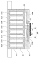
図8(a)は、1つの吐出モジュール200の斜視図、図8(b)は、その分解図である。吐出モジュール200の製造に際しては、まず、予め連通口31が設けられている支持部材30上に、記録素子基板10およびフレキシブル配線基板40を接着する。その後、記録素子基板10上の端子16と、フレキシブル配線基板40上の端子41と、をワイヤーボンディングによって接続し、その後、ワイヤーボンディング部(電気接続部)を封止材110により覆って封止する。フレキシブル配線基板40において記録素子基板10と反対側に位置する端子42は、電気配線基板90の接続端子93(図4参照)と電気的に接続される。支持部材30は、記録素子基板10を支持する支持体であると共に、記録素子基板10と流路部材210とを流体的に連通させる流路部材でもある。そのため、支持部材30としては、平面度が高く、また十分に高い信頼性をもって記録素子基板10と接合できるものが好ましい。材質としては、例えばアルミナや樹脂材料が好ましい。
(Discharge module)
8 (a) is a perspective view of one
(記録素子基板)
図9(a)は、記録素子基板10を吐出口13側から見た平面図、図9(b)は、図9(a)のIXb円部の拡大図、図9(c)は、図9(a)は、記録素子基板10を吐出口13と反対側から見た平面図である。図9(a)のように、記録素子基板10における吐出口形成部材12には、インク色毎に対応する4列の吐出口列14が形成されている。以降、複数の吐出口13が配列される吐出口列14の延在方向を「吐出口列方向」ともいう。
(Recording element substrate)
9 (a) is a plan view of the
図9(b)のように、各吐出口13に対応する位置には、記録素子15として、インクを吐出するためのエネルギを発生する吐出エネルギ発生素子が備えられている。本例における記録素子15は、熱エネルギによりインクを発泡させるための発熱素子(電気熱変換素子)である。隔壁22により、記録素子15を内部に備える圧力室23が区画されている。記録素子15は、記録素子基板10に設けられる電気配線(不図示)によって、図9(a)における端子16と電気的に接続されている。記録素子15は、電気配線基板90(図4参照)およびフレキシブル配線基板40(図8(a)参照)を介して、記録装置1000の制御回路から入力されるパルス信号に基づいて発熱することにより、インクを沸騰させる。この沸騰によって生じる発泡エネルギにより、吐出口13からインクが吐出される。記録素子基板10には、図9(b)のように、各吐出口列14に沿って延在するように、液体供給路18と液体回収路19が形成されている。液体供給路18は、吐出口列14の一方側に位置しており、供給口17aを介して吐出口13と連通する。液体回収路19は、吐出口列14の他方側に位置しており、回収口17bを介して吐出口13と連通する。
As shown in FIG. 9B, an ejection energy generating element for generating energy for ejecting ink is provided as a
図9(c)および図10のように、記録素子基板10において吐出口形成部材12と反対側に位置する面には、シート状の蓋部材20が積層されている。この蓋部材20には、液体供給路18および液体回収路19に連通する開口21が複数設けられている。本実施形態においては、液体供給路18の1つに対して2つの開口21が設けられ、液体回収路19の1つに対して1つの開口21が設けられている。これらの蓋部材20の開口21は、図5(a)における第1流路部材50の連通口51に連通する。蓋部材20は、図10のように、記録素子基板10の基板11に形成される液体供給路18および液体回収路19の壁の一部を形成する、蓋としての機能を有する。蓋部材20は、インクに対して十分な耐食性を有していること好ましく、また、インクの混色防止の観点から、開口21の開口形状および開口位置には高い精度が要求される。そのため、蓋部材20の材質として、感光性樹脂材料またはシリコン板を用い、フォトリソプロセスによって開口21を設けることが好ましい。このように蓋部材は、開口21によって流路のピッチを変換するものであり、その厚みは、圧力損失を考慮すると薄いことが望ましく、フィルム状の部材によって構成されることが望ましい。
As shown in FIGS. 9C and 10, a sheet-shaped
図10は、図9(a)におけるX−X線に沿って断面した記録素子基板10および蓋部材20の斜視図である。記録素子基板10においては、Siにより形成される基板11と、感光性の樹脂により形成される吐出口形成部材12と、が積層されており、基板11の裏面には蓋部材20が接合されている。基板11の一方側の面には記録素子15が形成されており(図9参照)、基板11の他方側の面には、吐出口列14に沿って延在する液体供給路18および液体回収路19を構成する溝が形成されている。基板11と蓋部材20とによって形成される液体供給路18および液体回収路19は、それぞれ、流路部材210内の共通供給流路211および共通回収流路212に接続される。したがって、液体供給路18と液体回収路19との間には差圧が生じる。液体吐出ヘッド3の複数の吐出口13からインクを吐出して画像を記録する際に、インクを吐出していない吐出口においては、液体供給路18と液体回収路19との間の差圧によってインクが流れる。すなわち、基板11における液体供給路18内のインクは、図10中の矢印Cのように、供給口17a、圧力室23、および回収口17bを経由して液体回収路19へ流れる。この流れによって、インクの吐出を休止している吐出口13および圧力室23において、吐出口13からの蒸発によって生じる増粘インク、および泡などの異物を液体回収路19へ回収することができる。また、吐出口13および圧力室23におけるインクの増粘を抑制することができる。液体回収路19へ回収されたインクは、蓋部材20の開口21および支持部材30の液体連通口31(図8(b)参照)から、流路部材210内の連通口51、個別回収流路214、および共通回収流路212を通って回収される。そのインクは、最終的には、記録装置1000の供給流路へ回収される。
FIG. 10 is a perspective view of the
つまり、記録装置本体から液体吐出ヘッド3へ供給されるインクは、下記の順に流動して、供給および回収される。インクは、まず、液体供給ユニット220の液体接続部111aから液体吐出ヘッド3の内部に流入する。そのインクは、ジョイントゴム100の穴、第3流路部材70の連通口72および共通流路溝71、第2流路部材60の共通流路溝62および連通口61、第1流路部材50の個別流路溝52および連通口51の順に供給される。その後、そのインクは、支持部材30の液体連通口31、蓋部材20の開口21、基板11の液体供給路18および供給口17aを順に通って、圧力室23に供給される。圧力室23に供給されたインクのうち、吐出口13から吐出されなかったインクは、基板11の回収口17bおよび液体回収路19、蓋部材20の開口21、支持部材30の液体連通口31を順に通って流れる。そのインクは、さらに、第1流路部材50の連通口51および個別流路溝52、第2流路部材60の連通口61および共通流路溝62、第3流路部材70の共通流路溝71および連通口72、ジョイントゴム100の穴を順に通って流れる。そのインクは、さらに、液体供給ユニット220の液体接続部111bを通って、液体吐出ヘッド3の外部へと流れる。図2のインクの循環経路において、液体接続部111aに流入したインクは、負圧制御ユニット230を経由してから、ジョイントゴム100の穴を通して供給される。
That is, the ink supplied from the recording device main body to the
このように、本実施形態の液体吐出ヘッドは、圧力室および吐出口近傍部におけるインクの増粘に起因する、インクの吐出方向のヨレおよび吐出不良の発生を抑制して、高画質の画像を記録することができる。 As described above, the liquid ejection head of the present embodiment suppresses the occurrence of twisting of the ink ejection direction and ejection failure due to thickening of the ink in the pressure chamber and the vicinity of the ejection port, and produces a high-quality image. Can be recorded.
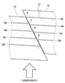
(記録素子基板間の位置関係)
図11は、互いに隣接する2つの吐出モジュール200における一方の記録素子基板10と、その他方の記録素子基板10と、の隣接部分の拡大平面図である。図9(a)のように、本実施形態においては平面が略平行四辺形の記録素子基板10が用いられる。図11のように、各記録素子基板10において吐出口13が配列される吐出口列14(14a,14b,14c,14d)は、記録媒体2の搬送方向(矢印Y方向)に対して、一定角度傾くように配置されている。これにより、記録素子基板10同士の隣接部における吐出口列14は、少なくとも1つの吐出口13が記録媒体2の搬送方向にオーバーラップする。図11においては、搬送方向に沿うD線上の2つの吐出口13が互いにオーバーラップする。このような吐出口列14の配置により、仮に、記録素子基板10の配備位置が所定位置から多少ずれた場合でも、互いにオーバーラップする吐出口13の駆動制御によって、記録画像における黒スジまたは白抜けなどを目立たなくすることができる。複数の記録素子基板10を千鳥配置ではなく、直線上(インライン)に配置した場合においても、図11のような構成を採用することができる。これにより、記録媒体2の搬送方向における液体吐出ヘッド3の長さを抑えつつ、記録素子基板10同士のつなぎ部に対応する記録画像における黒スジまたは白抜けなどを目立たなくすることができる。なお、記録素子基板の平面形状は、本実施形態のような平行四辺形に限定されず、例えば、長方形、台形、その他形状であってもよい。
(Positional relationship between recording element boards)
FIG. 11 is an enlarged plan view of an adjacent portion of one
(型内接合)
液体供給ユニット220は、図12(a)のように、流路形成部材2221と、流路蓋部材2231と、フィルタ221と、を含む。流路形成部材2221には、インクを液体吐出ユニットに供給するための液体供給路が形成され、流路蓋部材2231は、流路形成部材2221と接合してインクの漏出を防ぐ。フィルタ221は、液体供給路中を流れるインク内のゴミおよび気泡を除去する。流路形成部材2221は、その量産性の観点から、樹脂を射出成形して作製することが望ましい。
(Joining in the mold)
As shown in FIG. 12A, the
特に、本例のようなライン型の液体吐出ヘッドの場合には、シリアル型の液体吐出ヘッドに比べて構成部品が大型化する。そのため、流路形成部材2221を射出成形によって作製する際に、射出成型後の流路形成部材2221を金型から離型したときに、樹脂の硬化収縮に起因する捩れまたは反りが流路形成部材2221に生じて、その形状が変化するおそれがある。流路形成部材2221の形状が大きく変化した場合には、その流路形成部材2221と、フィルタ221などの部品と、を接合する際に、それらを良好に接合できなくなるおそれがある。具体的には、離型後の硬化収縮に起因する流路形成部材2221の形状変化によって、その流路形成部材2221におけるフィルタ221との接合面の平面度が低下し、その接合面の一部においてフィルタ221が接合できなくなるおそれがある。この場合には、フィルタ221がゴミおよび気泡の除去機能を果たせなくなる。また、このような流路形成部材2221に、射出成形によって製作した流路蓋部材2231を接合する場合には、その流路蓋部材2231の接合面も硬化収縮によって変形するおそれがある。この場合には、平面度の低い2つの接合面を接合しなければならず、それらの接合面の全てにおいて良好に接合することは難しい。つまり、2つの接合部品の接合面をインクが漏れないように密着させることができず、流路蓋部材2231の機能が損なわれるおそれがある。
In particular, in the case of a line-type liquid discharge head as in this example, the components are larger than those of the serial-type liquid discharge head. Therefore, when the flow
このような2つの接合部品を良好に接合するためには、流路形成部材2221の形状変化を矯正して、その平面度を高めることが必要となる。そのため、流路形成部材2221の形状変化の影響を小さく抑えた状態において、その流路形成部材2221に、フィルタ221および流路蓋部材2231を接合することが好ましい。また、それらの接合面の直下を治具により保持して、接合時に掛ける力を接合面に効率的に伝えることが好ましい。
In order to satisfactorily join such two joining parts, it is necessary to correct the shape change of the flow
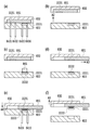
そこで本実施形態においては、流路形成部材2221の形状変化の影響を抑制するために、図13(a),(b)のような射出成形用金型を用いる。
Therefore, in the present embodiment, an injection molding die as shown in FIGS. 13 (a) and 13 (b) is used in order to suppress the influence of the shape change of the flow
本例の射出成形用金型は、図13(a)のように、成形位置811を有する固定側金型821と、可動側金型831と、を相対移動可能に備える。このような開閉可能な射出成形用金型の内部において、成型品である流路形成部材2221が射出成形される。また、図13(a)中の8401、8402、8403、8404は、樹脂を射出するためのバルブゲートである。図13(b)は、本例の射出成形用金型の平面図である。
As shown in FIG. 13A, the injection molding die of this example includes a fixed
図14(a),(b),(c)は、液体吐出ヘッド3の液体供給ユニット220を作製する際に、その液体供給ユニット220の構成部品である流路形成部材2221と、他の部品と、を接合および固定する工程を説明するための断面図である。これらの断面図は、図13(b)中のXIV−XIV線に沿う断面図である。
14 (a), (b), and (c) show the flow
図14(a)は、固定側金型821と可動側金型831とを型締めしてから、成形位置811に成形樹脂を充填して流路形成部材2221を射出成形する第1工程を示す。成形樹脂は、バルブゲートから射出される。その後の第2工程において、図14(b)のように可動側金型831を矢印A1方向に開く。射出成形された流路形成部材2221は、可動側金型831が矢印A1方向へ移動する際に固定側金型821に保持される。そのため、固定側金型821によって、硬化収縮に起因する流路形成部材2221の捩れおよび反りなどの形状変化が抑制できる。その後の第3工程において、図14(c)のように、流路形成部材2221を固定側金型821に残したまま、接合治具861を用いて、フィルタ2211を流路形成部材2221に接合する。このように、流路形成部材2221を固定側金型821に残すことにより、固定側金型821によって、フィルタ2211と流路形成部材2221との接合面の直下が隙間なく保持される。したがって、それらの接合時に掛ける力を接合面に効率的に伝えて、それらを良好に接合することができる。
FIG. 14A shows a first step of molding the fixed-
また、流路形成部材2221の接合面に、その流路形成部材2221に接合する接合対象の部品を押し当て、流路形成部材2221の硬化収縮による形状変化を矯正することが好ましい。さらに、その矯正の効果を高めるため、剛性の高い治具等を用いて、接合対象の部品を流路形成部材2221の接合面に押し当てることが好ましい。接合対象の部品は、例えば、液体供給路内を流れるインク中に含まれるゴミおよび気泡を除去するためのフィルタ2211、インクの漏れが発生しないように液体供給路に蓋をする流路蓋部材2231、および流路が形成された第2の流路形成部材などを含む。接合対象の部品としては、液体供給ユニット220に機能を付与することのできる部品が好ましい。また、これらの部品を接合して形成される流路の流路抵抗は低いことが好ましい。また、接合対象の部品として、大面積のフィルタ、流路断面積を大きく設定可能な第2の流路形成部材および流路蓋部材が好ましい。
Further, it is preferable to press the component to be joined to the flow
また、流路形成部材2221に接合する部品は複数であってもよい。例えば、図12(b)のように、複数のフィルタ2212,2213と複数の流路とが並列する流路を構成するように、多色のインクに対応する液体供給ユニット220を作製することができる。また、液体供給ユニット220は、前述した液体吐出ユニット300の一部を構成する流路形成部材を含む構成であってもよい。例えば、液体供給ユニット220は、図12(c)のような流路形成部材2223,2224,2225を接合する構成とすることができる。この場合には、固定側金型821に残される流路形成部材2223と、その流路形成部材2223に接合される流路形成部材2224と、が接合される。流路形成部材2224側の接合面は、流路形成部材2223側の接合面よりも大きくてもよく、または略同面積であってもよい。
Further, there may be a plurality of parts to be joined to the flow
流路形成部材2221にフィルタ221を接合するためには、流路形成部材2221の樹脂を溶かしてフィルタ221に染み込ませて固定して、それらの接合強度を高めることができる熱溶着、超音波溶着、振動溶着等が好ましい。また、流路形成部材2221に第2の流路形成部材などの樹脂成形部品を接合するためには、固定側金型821が流路形成部材2221の接合箇所の直下を隙間なく受けることができることを活かして、超音波溶着、振動溶着、レーザー溶着などが好ましい。
In order to bond the
以上の工程により、流路形成部材の形状変化の影響を抑制しつつ、その流路形成部材に種々の部品を接合するため、液体供給ユニットを高精度に製造することができる。また、このような液体供給ユニットを記録ヘッドと結合することにより、高い画像品質を実現するライン型の液体吐出ヘッドを作製することができる。 By the above steps, various parts are joined to the flow path forming member while suppressing the influence of the shape change of the flow path forming member, so that the liquid supply unit can be manufactured with high accuracy. Further, by combining such a liquid supply unit with a recording head, it is possible to manufacture a line-type liquid discharge head that realizes high image quality.
(第2の実施形態)
本実施形態における液体供給ユニット220は、第1の実施形態と同様に、流路形成部材2221と、流路蓋部材2231と、フィルタ221と、を含む。本例においては、1つの金型内において、流路形成部材2221および流路蓋部材2231の2つの成形部品と、フィルタ221などの部品と、を接合する。流路形成部材2221と接合する部品は流路蓋部材2231に限定されず、流路が形成された第2の流路形成部材2222等、種々の他の機能をもつ部品であってもよい。
(Second embodiment)
The
図15(a)は、本発明の第2の実施形態における射出成形用の金型の斜視図であり、図15(b)は、その金型の平面図である。本例の金型は、成形位置812,813を有する固定側金型822と、可動側金型832と、によって構成され、可動側金型832には、ダイスライド機構851(図16(d)参照)が配置されている。金型は、その内部に、流路形成部材2223を成形する第1の成形位置812と、流路蓋部材2231を成形する第2の成形位置813と、を有する。バルブゲート8401から8404は、流路形成部材2223を成形するための樹脂を射出し、バルブゲート8405から8408は、流路蓋部材2231を成形するための樹脂を射出する。また、バルブゲート8409から8412は、流路形成部材2223と流路蓋部材2231とを接合するための樹脂を射出する。
15 (a) is a perspective view of a mold for injection molding according to the second embodiment of the present invention, and FIG. 15 (b) is a plan view of the mold. The mold of this example is composed of a fixed-
図16(a)から(f)は、液体供給ユニット220を製造する際に、その構成部品である流路形成部材2223と、他の部品と、を接合して固定する工程を説明するための断面図である。これらの断面図は、図15(b)中のXVI−XVI線の沿う断面図である。
16 (a) to 16 (f) are for explaining a process of joining and fixing the flow
まず、第1工程においては、図16(a)のように、固定側金型822と可動側金型832とを型締めしてから、第1の成形位置812において流路形成部材2221を射出成形し、第2の成形位置813において流路蓋部材2231を射出成形する。流路形成部材2221および流路蓋部材2231の成形樹脂は、それぞれの成形位置に配置されているバルブゲート8401から8408から射出される。その後の第2工程においては、図16(b)のように、可動側金型832が矢印A2方向へ移動して金型を開く。第2の成形位置813にて成形された流路蓋部材2231は、可動側金型832に保持されたまま、可動側金型832と共に移動する。また、第1の成形位置812にて成形された流路形成部材2221は、固定側金型822に保持されたまま移動しない。このように、射出成形された流路蓋部材2231が可動側金型832に保持され、射出成形された流路形成部材2223が固定側金型822に保持される。したがって、硬化収縮に起因する流路蓋部材2231および流路形成部材2223の捩れおよび反りなどの形状変化を抑制することができる。
First, in the first step, as shown in FIG. 16A, the fixed
その後の第3工程においては、図16(c)のように、固定側金型822に流路形成部材2221を残したまま、接合治具861を用いて、第2の流路形成部材2222(フィルタ221等を含む)を接合する。このとき、流路形成部材2221を固定側金型822に残すことにより、固定側金型822によって、流路形成部材2221における接合面の直下が隙間なく保持される。したがって、接合時に掛ける力を接合面に効率的に伝えて、良好な接合が可能となる。また、流路形成部材2222などの接合対象の部品を流路形成部材2221の接合面に押し当て、流路形成部材2221の硬化収縮による形状変化を矯正することが好ましい。さらに、その矯正の効果を高めるため、剛性の高い治具等を用いて、接合対象の部品を流路形成部材2221の接合面に押し当てることが好ましい。
In the subsequent third step, as shown in FIG. 16C, the second flow path forming member 2222 (2) using the joining
接合対象の部品は、例えば、液体供給路内を流れる液体中に含まれるゴミおよび気泡を除去するためのフィルタ221、流路が形成された第2の流路形成部材2222、インクの漏れが発生しないように液体供給路に蓋をする流路蓋部材2231などを含む。流路形成部材2221に対して、種々の機能をもつ部品を接合することができる。また、これらの部品を接合して形成される流路の流路抵抗は低いことが好ましい。また、接合対象の部品として、大面積のフィルタ、流路断面積を大きく設定可能な第2の流路形成部材および流路蓋部材が好ましい。また、流路形成部材2221に接合する部品は複数であってもよく、複数のフィルタ221と複数の流路が並列する流路を構成するように、多色のインクに対応する液体供給ユニット220を製造することができる。
The parts to be joined include, for example, a
また、フィルタ221を接合するためには、流路形成部材2221の樹脂を溶かしてフィルタ221に染み込ませて固定して、それらの接合強度を高めることができる熱溶着、超音波溶着、振動溶着等が好ましい。また、流路形成部材2221に第2の流路形成部材2222などの樹脂成形部品を接合するためには、固定側金型821が流路形成部材2221の接合箇所の直下を隙間なく受けられることを活かして、超音波溶着、振動溶着、レーザー溶着などが好ましい。
Further, in order to join the
その後、図16(d)のように、可動側金型832が流路蓋部材2231を保持したまま矢印A3方向に移動し、その流路蓋部材2231と、固定側金型822に保持されている流路形成部材2221と、を対向させる。このような移動を実現するために、可動側金型832は、矢印A3へスライド可能なダイスライド機構851を備えており、可動側金型832の外縁は移動せずに、可動側金型832がダイスライド機構851によって移動される。このような可動側金型832の移動は、図16(b)のような型開きの後であれば、図16(c)のような流路形成部材2222(フィルタ221等を含む)等の部品を接合前であってもよい。
After that, as shown in FIG. 16D, the
次に、図16(e)のように、固定側金型822に向かって、可動側金型832が矢印A4の方向へ移動して、金型を閉じる。このとき、可動側金型832に保持されている流路蓋部材2231側の接合箇所は、固定側金型822に保持されている流路形成部材2221側の接合箇所に当接する。その後、流路形成部材2221と流路蓋部材2231との当接部を接合する。この接合のために、流路形成部材2223と流路蓋部材2231との当接部に、バルブゲート8409から8412から樹脂材料を射出する。このような接合を一連の工程内において実施できるため、液体供給ユニット220の製造におけるタクトタイムの短縮が可能である。また、射出成形された流路形成部材2221を固定側金型822に保持し、射出成形された流路蓋部材2231を可動側金型832保持することにより、それらの部材2221,2231の硬化収縮に起因する捩れおよび反りなどの形状変化を抑制することができる。
Next, as shown in FIG. 16E, the
接合対象の成形部材を接合するために、それらの当接部に充填する接合材料(樹脂材料)は、接合強度を高めるために、接合対象の成形材料と同程度の線膨張係数であることが好ましい。また、それらの当接部には、接合材料を充填する際の充填圧力が作用する。この充填圧力に拘わらず、接合対象の成形部材を適正な当接状態を維持するためには、流路形成部材2221と流路蓋部材2231に対して、この充填圧力が同等に掛かることが望ましい。
In order to join the molded members to be joined, the joining material (resin material) to be filled in the contact portions thereof may have a linear expansion coefficient similar to that of the molding material to be joined in order to increase the joining strength. preferable. Further, the filling pressure at the time of filling the joining material acts on those abutting portions. In order to maintain an appropriate contact state between the molded members to be joined regardless of the filling pressure, it is desirable that the filling pressure is applied equally to the flow
例えば、図18のように、流路Lを形成する流路形成部材2221と、流路蓋部材2231と、の間に、接合材料(樹脂材料)2241を充填して流路形成部材2221と流路蓋部材2231とを接合する場合を想定する。この場合、流路形成部材2221側の接合面2221Aが接合材料2241に接し、流路蓋部材2231側の接合面2231A,2231B,2231Cが接合材料2241に接する。接合面2221Aを流路蓋部材2231側に投影したしときの投影面積は、接合面2221Aの面積に対応する。一方、接合面2231A,2231B,2231Cを流路形成部材2221側に投影したときの投影面積は、接合面2231Aの面積に対応する。これらの投影面積が略等しくなるように、流路形成部材2221と流路蓋部材2231の接合面を設定する。これにより、流路形成部材2221と流路蓋部材2231との接合方向において、それらに対して、接合材料2241の充填圧力を同等に掛けることができる。この結果、流路形成部材2221および流路蓋部材2231の変形を抑制し、かつ、それらの間を密閉するために充填される接合材料の漏れ等の弊害を防止することができる。これらの結果、流路形成部材2221と流路蓋部材2231とを適確に接合して、それらの間を確実に封止することができる。したがって、接合材料2241は封止材料としても機能する。
For example, as shown in FIG. 18, a joining material (resin material) 2241 is filled between the flow
また、接合対象の部材の当接部に充填する樹脂材料は、接合対象の部材の成形材料と相溶する材料であればよく、接合対象の部材の成形材料と異なる材料であっても同様の効果が得られる。また、樹脂材料の充填領域が大面積、あるいは複雑に入り組んでいる場合には、接合対象の部材の成形材料と相溶する流動性の高い樹脂材料を充填することが好ましい。 Further, the resin material to be filled in the contact portion of the member to be joined may be any material that is compatible with the molding material of the member to be joined, and the same may be applied even if the material is different from the molding material of the member to be joined. The effect is obtained. Further, when the filling region of the resin material has a large area or is complicatedly complicated, it is preferable to fill the resin material having high fluidity that is compatible with the molding material of the member to be joined.
最後に、図16(f)のように、可動側金型832が矢印A5方向へ移動して型開きし、3つの部材2221,2222,2231によって構成された液体供給ユニット220を取り出す。本例において、流路形成部材2221と第2の流路形成部材2222(フィルタ等を含む)との接合面と、流路形成部材2221と流路蓋部材2231との接合面と、は異なる平面上に位置する。
Finally, as shown in FIG. 16 (f), the
前述した実施形態と同様に、本実施形態においても図12(b)のように、複数のフィルタ2212,2213と複数の流路とが並列する流路を構成するように、多色のインクに対応する液体供給ユニット220を製造することができる。また、液体供給ユニット220は、前述した液体吐出ユニット300の一部を構成する流路形成部材を含む構成であってもよい。例えば、液体供給ユニット220は、図12(c)のような流路形成部材2223,2224,2225を接合する構成とすることができる。この場合には、固定側金型821に残される流路形成部材2223と、その流路形成部材2223に接合される流路形成部材2224と、が接合される。
Similar to the above-described embodiment, in the present embodiment as well, as shown in FIG. 12B, the multicolor ink is used so as to form a flow path in which the plurality of
(第3の実施形態)
本発明は、同一金型内において、液体供給ユニットを構成する3つの以上の部材(各流路形成部材を含む)を射出成形して、それらを接合する場合にも有効である。前述した実施形態と同様に、同一金型内において複数の部材を同時に射出成形した後、それらの部材を当接させてから接合材料(封止材料)を充填することにより、それらの部材を接合して液体供給ユニット220を製造することができる。例えば、図17のように、流路形成部材2221(1),2221(2)と流路蓋部材2231との3つの部材を同時に射出成形してから、それらを接合材料により接合することにより液体供給ユニット220を製造することができる。その際、それら3つの部材を同時に接合してもよく、あるいは2つの部材を先に接合してから、残りの1つと接合するように2回に分けて接合してもよい。接合する3つの部材のうち、2つの部材は、金型に残したまま接合することが好ましい。
(Third embodiment)
The present invention is also effective when three or more members (including each flow path forming member) constituting the liquid supply unit are injection-molded in the same mold and joined to each other. Similar to the above-described embodiment, a plurality of members are injection-molded at the same time in the same mold, and then the members are brought into contact with each other and then filled with a joining material (sealing material) to join the members. The
本発明は、種々の液体を供給する液体供給ユニット、および種々の液体を吐出可能な液体吐出ヘッドの製造方法として広く適用することができる。また本発明は、種々の媒体(シートなど)に対して、種々の処理(記録、加工、塗布など)を施すための液体を供給および吐出する液体供給ユニットおよび液体吐出ヘッドの製造方法としても適用可能である。その媒体(記録媒体を含む)は、紙、プラスチック、フィルム、織物、金属、フレキシブル基板等、材質は問わず、インクを含む種々の液体が付与される種々の媒体を含む。 The present invention can be widely applied as a method for manufacturing a liquid supply unit for supplying various liquids and a liquid discharge head capable of discharging various liquids. The present invention is also applied as a method for manufacturing a liquid supply unit and a liquid discharge head for supplying and discharging a liquid for performing various treatments (recording, processing, coating, etc.) on various media (sheets, etc.). It is possible. The medium (including a recording medium) includes various media to which various liquids including ink are applied, regardless of the material, such as paper, plastic, film, woven fabric, metal, and flexible substrate.
1000 記録装置(液体吐出装置)
220 液体供給ユニット
221 フィルタ
222 流路形成部材
223 流路蓋部材
3 液体吐出ヘッド
300 液体吐出ユニット
82 固定側金型
83 可動側金型
1000 Recording device (liquid discharge device)
220
82 Fixed side mold
83 Movable side mold
Claims (11)
前記型開き工程において、前記成形工程にて射出成形された前記第1部材を前記第1金型に残し、かつ前記成形工程にて射出成形された前記第2部材を前記第2金型に残したまま、前記第1および第2金型を開くことを特徴とする請求項1に記載の液体供給ユニットの製造方法。 In the molding step, the first and second members are injection-molded.
In the mold opening step, the first member injection-molded in the molding step is left in the first mold, and the second member injection-molded in the molding step is left in the second mold. The method for manufacturing a liquid supply unit according to claim 1, wherein the first and second molds are opened while they are still in place.
Priority Applications (2)
| Application Number | Priority Date | Filing Date | Title |
|---|---|---|---|
| JP2016228084A JP6971563B2 (en) | 2016-11-24 | 2016-11-24 | Manufacturing method of liquid supply unit and manufacturing method of liquid discharge head |
| US15/794,232 US20180141247A1 (en) | 2016-11-24 | 2017-10-26 | Method of manufacturing liquid supply unit and method of manufacturing liquid ejecting head |
Applications Claiming Priority (1)
| Application Number | Priority Date | Filing Date | Title |
|---|---|---|---|
| JP2016228084A JP6971563B2 (en) | 2016-11-24 | 2016-11-24 | Manufacturing method of liquid supply unit and manufacturing method of liquid discharge head |
Publications (3)
| Publication Number | Publication Date |
|---|---|
| JP2018083351A JP2018083351A (en) | 2018-05-31 |
| JP2018083351A5 JP2018083351A5 (en) | 2019-12-19 |
| JP6971563B2 true JP6971563B2 (en) | 2021-11-24 |
Family
ID=62144240
Family Applications (1)
| Application Number | Title | Priority Date | Filing Date |
|---|---|---|---|
| JP2016228084A Active JP6971563B2 (en) | 2016-11-24 | 2016-11-24 | Manufacturing method of liquid supply unit and manufacturing method of liquid discharge head |
Country Status (2)
| Country | Link |
|---|---|
| US (1) | US20180141247A1 (en) |
| JP (1) | JP6971563B2 (en) |
Families Citing this family (1)
| Publication number | Priority date | Publication date | Assignee | Title |
|---|---|---|---|---|
| JP6877965B2 (en) * | 2016-11-24 | 2021-05-26 | キヤノン株式会社 | Manufacturing method of liquid supply unit |
Family Cites Families (17)
| Publication number | Priority date | Publication date | Assignee | Title |
|---|---|---|---|---|
| JP2920150B2 (en) * | 1993-06-30 | 1999-07-19 | 株式会社日本製鋼所 | Method for forming hollow body product and mold device used for carrying out the method |
| US5556541A (en) * | 1994-04-26 | 1996-09-17 | Filtertek, Inc. | Process for making hermetically sealed filter units and filters made thereby |
| JPH08316652A (en) * | 1995-05-17 | 1996-11-29 | Sanyo Electric Co Ltd | Portable power source |
| JPH09187938A (en) * | 1996-01-08 | 1997-07-22 | Canon Inc | Ink jet head and ink jet recording apparatus |
| JPH09254383A (en) * | 1996-03-19 | 1997-09-30 | Rohm Co Ltd | Color ink jet printer |
| JP3789178B2 (en) * | 1996-11-19 | 2006-06-21 | 株式会社アズマ工機 | Heat staking equipment |
| JP3390131B2 (en) * | 1997-11-14 | 2003-03-24 | ジー・ピー・ダイキョー株式会社 | Method and apparatus for producing synthetic resin hollow body incorporating intermediate and hollow body made of synthetic resin |
| JPH11240168A (en) * | 1998-02-25 | 1999-09-07 | Canon Inc | Ink tank and manufacture for thereof |
| JP3368203B2 (en) * | 1998-06-02 | 2003-01-20 | ジー・ピー・ダイキョー株式会社 | Method and apparatus for manufacturing synthetic resin hollow body |
| US6210619B1 (en) * | 1998-10-19 | 2001-04-03 | Ford Motor Company | Method for manufacturing a two-piece plastic assembly |
| JP3027150B1 (en) * | 1998-11-13 | 2000-03-27 | 大協株式会社 | Method and apparatus for manufacturing hollow body made of synthetic resin incorporating intermediate |
| TW200532103A (en) * | 2004-03-29 | 2005-10-01 | Mitsubishi Electric Corp | Fuel supply system |
| JP4854281B2 (en) * | 2005-11-29 | 2012-01-18 | キヤノン株式会社 | Recording head, ink tank, and manufacturing method of recording head |
| KR101141004B1 (en) * | 2007-03-09 | 2012-05-02 | 아사히 카세이 쿠라레 메디칼 가부시키가이샤 | Method of forming body fluid purification cassette |
| JP2010082894A (en) * | 2008-09-30 | 2010-04-15 | Seiko Epson Corp | Liquid ejecting head, method for manufacturing the same, and liquid ejecting apparatus |
| JP5515302B2 (en) * | 2009-01-27 | 2014-06-11 | セイコーエプソン株式会社 | Mold apparatus and method for producing molded product |
| JP5549085B2 (en) * | 2009-02-23 | 2014-07-16 | セイコーエプソン株式会社 | Method for manufacturing molded article and liquid supply unit |
-
2016
- 2016-11-24 JP JP2016228084A patent/JP6971563B2/en active Active
-
2017
- 2017-10-26 US US15/794,232 patent/US20180141247A1/en not_active Abandoned
Also Published As
| Publication number | Publication date |
|---|---|
| JP2018083351A (en) | 2018-05-31 |
| US20180141247A1 (en) | 2018-05-24 |
Similar Documents
| Publication | Publication Date | Title |
|---|---|---|
| US10549533B2 (en) | Flow path structure, liquid ejecting head, and liquid ejecting apparatus | |
| WO2016152166A1 (en) | Liquid ejecting head and liquid ejecting apparatus | |
| US8727503B2 (en) | Liquid jet recording head and manufacturing method thereof | |
| CN109203717B (en) | Control method of liquid ejection apparatus | |
| JP2019014172A (en) | Liquid discharge head | |
| JP6987548B2 (en) | Liquid discharge head and liquid discharge device | |
| JP5856493B2 (en) | Liquid ejecting head and liquid ejecting apparatus | |
| JP6768467B2 (en) | Manufacturing method of liquid discharge head | |
| JP2017121794A (en) | Liquid discharge device and control method for liquid discharge device | |
| CN107825855B (en) | The manufacturing method of ink gun and ink gun | |
| JP6971563B2 (en) | Manufacturing method of liquid supply unit and manufacturing method of liquid discharge head | |
| JP2017071163A (en) | Liquid discharge head, liquid discharge unit and liquid discharge device | |
| US10532574B2 (en) | Method of manufacturing liquid ejecting head, and liquid ejecting head | |
| US6623094B2 (en) | Ink jet recording device | |
| JP6877965B2 (en) | Manufacturing method of liquid supply unit | |
| EP1336497B1 (en) | Ink-jet printhead and method of manufacturing the same | |
| JP7057111B2 (en) | Manufacturing method of sealing mechanism | |
| US11613130B2 (en) | Sealing member, method of manufacturing the same, pressure adjustment mechanism, liquid ejection head, and liquid ejection apparatus | |
| JP6672913B2 (en) | Liquid discharge head, liquid discharge unit, device for discharging liquid | |
| US20100201760A1 (en) | Liquid ejecting head, method of manufacturing the same, and liquid ejecting apparatus | |
| JP3731484B2 (en) | Ink jet recording apparatus and manufacturing method thereof | |
| US12115787B2 (en) | Liquid ejection head and method of manufacturing liquid ejection head | |
| JP7602720B2 (en) | Joint member, liquid ejection head, liquid ejection unit, and liquid ejection device | |
| JP7414495B2 (en) | Manufacturing method of liquid ejection head | |
| JP7707260B2 (en) | LIQUID DISCHARGE UNIT AND LIQUID DISCHARGE APPARATUS |
Legal Events
| Date | Code | Title | Description |
|---|---|---|---|
| A521 | Request for written amendment filed |
Free format text: JAPANESE INTERMEDIATE CODE: A523 Effective date: 20191106 |
|
| A621 | Written request for application examination |
Free format text: JAPANESE INTERMEDIATE CODE: A621 Effective date: 20191106 |
|
| A131 | Notification of reasons for refusal |
Free format text: JAPANESE INTERMEDIATE CODE: A131 Effective date: 20200825 |
|
| A977 | Report on retrieval |
Free format text: JAPANESE INTERMEDIATE CODE: A971007 Effective date: 20200826 |
|
| A521 | Request for written amendment filed |
Free format text: JAPANESE INTERMEDIATE CODE: A523 Effective date: 20201014 |
|
| A131 | Notification of reasons for refusal |
Free format text: JAPANESE INTERMEDIATE CODE: A131 Effective date: 20210316 |
|
| A521 | Request for written amendment filed |
Free format text: JAPANESE INTERMEDIATE CODE: A523 Effective date: 20210423 |
|
| TRDD | Decision of grant or rejection written | ||
| A01 | Written decision to grant a patent or to grant a registration (utility model) |
Free format text: JAPANESE INTERMEDIATE CODE: A01 Effective date: 20211005 |
|
| A61 | First payment of annual fees (during grant procedure) |
Free format text: JAPANESE INTERMEDIATE CODE: A61 Effective date: 20211102 |
|
| R151 | Written notification of patent or utility model registration |
Ref document number: 6971563 Country of ref document: JP Free format text: JAPANESE INTERMEDIATE CODE: R151 |