JP6968674B2 - Image forming device - Google Patents
Image forming device Download PDFInfo
- Publication number
- JP6968674B2 JP6968674B2 JP2017230995A JP2017230995A JP6968674B2 JP 6968674 B2 JP6968674 B2 JP 6968674B2 JP 2017230995 A JP2017230995 A JP 2017230995A JP 2017230995 A JP2017230995 A JP 2017230995A JP 6968674 B2 JP6968674 B2 JP 6968674B2
- Authority
- JP
- Japan
- Prior art keywords
- sheet
- motor
- image forming
- value
- rotating body
- Prior art date
- Legal status (The legal status is an assumption and is not a legal conclusion. Google has not performed a legal analysis and makes no representation as to the accuracy of the status listed.)
- Active
Links
Images


Landscapes
- Fixing For Electrophotography (AREA)
- Paper Feeding For Electrophotography (AREA)
- Control Or Security For Electrophotography (AREA)
Description
本発明は、画像形成装置におけるモータの制御に関する。 The present invention relates to the control of a motor in an image forming apparatus.
従来、画像形成装置において、記録媒体に転写されたトナー像を加熱及び加圧によって当該記録媒体に定着させる定着ローラを有する定着装置が知られている。 Conventionally, in an image forming apparatus, a fixing device having a fixing roller for fixing a toner image transferred to a recording medium to the recording medium by heating and pressurizing is known.
定着装置においては、定着ローラのニップ部を通過した記録媒体が定着ローラから分離しない可能性がある。即ち、定着ローラのニップ部を通過した記録媒体が定着ローラに貼り付いた状態で定着ローラが回転し、記録媒体が定着ローラに巻き付いてしまう可能性がある。 In the fixing device, the recording medium that has passed through the nip portion of the fixing roller may not be separated from the fixing roller. That is, there is a possibility that the fixing roller rotates in a state where the recording medium that has passed through the nip portion of the fixing roller is attached to the fixing roller, and the recording medium is wound around the fixing roller.
特許文献1では、定着ローラを駆動するモータにかかる負荷トルクに基づいて、記録媒体が定着ローラに巻き付いたか否かを検出する構成が述べられている。具体的には、記録媒体の先端が定着ローラのニップ部に突入することに起因して負荷トルクが増大した後に、当該記録媒体の先端が再びニップ部に突入することに起因して負荷トルクが増大すると記録媒体が定着ローラに巻き付いたことが判定される。即ち、前記特許文献1では、記録媒体が定着ローラに貼り付いた状態で定着ローラが1回転したら記録媒体が定着ローラに巻き付いたことが判定される。なお、当該判定結果はユーザに通知される。 Patent Document 1 describes a configuration for detecting whether or not the recording medium is wound around the fixing roller based on the load torque applied to the motor for driving the fixing roller. Specifically, after the load torque increases due to the tip of the recording medium plunging into the nip portion of the fixing roller, the load torque increases due to the tip of the recording medium plunging into the nip portion again. When it increases, it is determined that the recording medium is wound around the fixing roller. That is, in Patent Document 1, it is determined that the recording medium is wound around the fixing roller when the fixing roller makes one rotation while the recording medium is attached to the fixing roller. The determination result is notified to the user.
前記特許文献1では、記録媒体が貼り付いた定着ローラが1回転した後に判定結果がユーザに通知されるため、記録媒体を定着ローラから取り除くことが困難になってしまう。 In Patent Document 1, since the determination result is notified to the user after one rotation of the fixing roller to which the recording medium is attached, it becomes difficult to remove the recording medium from the fixing roller.
この場合、記録媒体が搬送方向において、定着ローラよりも下流側に記録媒体の有無を検知するセンサを設けることが考えられるが、センサを設けることに起因して装置が大型化したりコストが増大したりしてしまう。 In this case, it is conceivable to provide a sensor for detecting the presence or absence of the recording medium on the downstream side of the fixing roller in the transport direction of the recording medium, but the provision of the sensor increases the size of the device and the cost. I will do it.
上記課題に鑑み、本発明は、シートが回転体に貼り付いた状態で当該回転体が1回転してしまうことをより安価な構成で抑制することを目的とする。 In view of the above problems, it is an object of the present invention to prevent the rotating body from rotating once while the sheet is attached to the rotating body with a cheaper configuration.
上記課題を解決するために、本発明にかかる画像形成装置は、
シートに画像を形成する画像形成手段と、
ヒータと回転体とを備え、前記回転体によって前記シートを搬送しながら、前記画像形成手段によって当該シートに形成された前記画像を前記ヒータの熱によって当該シートに定着させる定着手段と、
前記回転体に隣接し且つ前記シートが搬送される搬送方向において前記回転体よりも下流側に設けられ、前記シートを搬送する搬送ローラと、
前記搬送ローラを駆動するモータと、
前記モータの回転子の回転位相を決定する位相決定手段と、
前記モータの回転子の目標位相を表す指令位相と前記位相決定手段によって決定された前記回転子の回転位相との偏差が小さくなるように、前記モータの巻線に流れる駆動電流を制御する第1制御手段と、
前記シートの搬送を制御する第2制御手段と、
前記モータの回転子にかかる負荷トルクに対応するパラメータの値の絶対値が所定値を超えると所定の信号を出力する出力手段と、
を有し、
前記回転体のニップ部から前記搬送ローラのニップ部までの距離は、前記回転体の周長よりも短く、
前記制御手段は、前記回転体と前記搬送ローラとが異なる速度で回転するように前記モータの巻線に流れる駆動電流を制御し、
前記第2制御手段は、前記シートの先端が前記回転体のニップ部よりも上流側の所定位置に到達してから所定時間が経過するまでの期間に前記所定の信号が前記出力手段から出力されない場合は前記シートの搬送を停止し、前記期間に前記所定の信号が前記出力手段から出力された場合は前記シートの搬送を継続し、
前記所定時間は、前記所定位置に到達した前記シートの先端が前記搬送ローラのニップ部に到達するのに要する時間よりも長く、且つ、前記所定位置に到達した前記シートの先端が、前記回転体のニップ部から前記搬送方向において前記回転体の周長分下流側の位置に到達するのに要する時間よりも短いことを特徴とする。
In order to solve the above problems, the image forming apparatus according to the present invention is
An image forming means for forming an image on a sheet,
A heater with a rotating body, while conveying the sheet by said rotary member, and a fixing means for fixing to the sheet the image formed on the sheet by the heat of the heater by said image forming means,
A transport roller adjacent to the rotating body and provided on the downstream side of the rotating body in the transport direction in which the sheet is transported, and a transport roller for transporting the sheet.
The motor that drives the transfer roller and
A phase determining means for determining the rotational phase of the rotor of the motor,
A first that controls the drive current flowing through the winding of the motor so that the deviation between the command phase representing the target phase of the rotor of the motor and the rotation phase of the rotor determined by the phase determining means becomes small. Control means and
A second control means for controlling the transfer of the sheet,
An output means that outputs a predetermined signal when the absolute value of the parameter value corresponding to the load torque applied to the rotor of the motor exceeds a predetermined value.
Have,
The distance from the nip portion of the rotating body to the nip portion of the transport roller is shorter than the peripheral length of the rotating body.
The control means controls the drive current flowing through the winding of the motor so that the rotating body and the transport roller rotate at different speeds.
The second control means does not output the predetermined signal from the output means during the period from when the tip of the sheet reaches the predetermined position on the upstream side of the nip portion of the rotating body until the predetermined time elapses. In that case, the transfer of the sheet is stopped, and when the predetermined signal is output from the output means during the period, the transfer of the sheet is continued.
The predetermined time is longer than the time required for the tip of the sheet that has reached the predetermined position to reach the nip portion of the transport roller, and the tip of the sheet that has reached the predetermined position is the rotating body. It is characterized in that it is shorter than the time required to reach the position on the downstream side by the peripheral length of the rotating body from the nip portion of the above.
本発明によれば、シートが回転体に貼り付いた状態で当該回転体が1回転してしまうことをより安価な構成で抑制することができる。 According to the present invention, it is possible to prevent the rotating body from rotating once while the sheet is attached to the rotating body with a cheaper configuration.
以下に図面を参照して、本発明の好適な実施の形態を説明する。ただし、この実施の形態に記載されている構成部品の形状及びそれらの相対配置などは、この発明が適用される装置の構成や各種条件により適宜変更されるべきものであり、この発明の範囲が以下の実施の形態に限定される趣旨のものではない。なお、以下の説明においては、モータ制御装置が画像形成装置に設けられる場合について説明するが、モータ制御装置が設けられるのは画像形成装置に限定されるわけではない。例えば、記録媒体や原稿等のシートを搬送するシート搬送装置等にも用いられる。 Hereinafter, preferred embodiments of the present invention will be described with reference to the drawings. However, the shapes of the components and their relative arrangements described in this embodiment should be appropriately changed depending on the configuration of the apparatus to which the present invention is applied and various conditions, and the scope of the present invention is the scope of the present invention. It is not limited to the following embodiments. In the following description, the case where the motor control device is provided in the image forming apparatus will be described, but the case where the motor control device is provided is not limited to the image forming apparatus. For example, it is also used in a sheet transfer device for transporting a sheet such as a recording medium or a document.
〔第1実施形態〕
[画像形成装置]
図1は、本実施形態で用いられるシート搬送装置を有するモノクロの電子写真方式の複写機(以下、画像形成装置と称する)100の構成を示す断面図である。なお、画像形成装置は複写機に限定されず、例えば、ファクシミリ装置、印刷機、プリンタ等であっても良い。また、記録方式は、電子写真方式に限らず、例えば、インクジェット等であっても良い。更に、画像形成装置の形式はモノクロ及びカラーのいずれの形式であっても良い。
[First Embodiment]
[Image forming device]
FIG. 1 is a cross-sectional view showing the configuration of a monochrome electrophotographic copying machine (hereinafter referred to as an image forming apparatus) 100 having a sheet transporting apparatus used in the present embodiment. The image forming apparatus is not limited to the copying machine, and may be, for example, a facsimile apparatus, a printing machine, a printer, or the like. Further, the recording method is not limited to the electrophotographic method, and may be, for example, an inkjet method. Further, the format of the image forming apparatus may be either monochrome or color.
以下に、図1を用いて、画像形成装置100の構成および機能について説明する。図1に示すように、画像形成装置100は、原稿給送装置201、読取装置202及び画像印刷装置301を有する。
Hereinafter, the configuration and function of the
原稿給送装置201の原稿積載部203に積載された原稿は、給紙ローラ204によって1枚ずつ給紙され、搬送ガイド206に沿って読取装置202の原稿ガラス台214上に搬送される。更に、原稿は、搬送ベルト208によって一定速度で搬送されて、排紙ローラ205によって不図示の排紙トレイへ排紙される。読取装置202の読取位置において照明209によって照明された原稿画像からの反射光は、反射ミラー210、211、212からなる光学系によって画像読取部111に導かれ、画像読取部111によって画像信号に変換される。画像読取部111は、レンズ、光電変換素子であるCCD、CCDの駆動回路等で構成される。画像読取部111から出力された画像信号は、ASIC等のハードウェアデバイスで構成される画像処理部112によって各種補正処理が行われた後、画像印刷装置301へ出力される。前述の如くして、原稿の読取が行われる。即ち、原稿給送装置201及び読取装置202は、原稿読取装置として機能する。
The documents loaded on the
また、原稿の読取モードとして、第1読取モードと第2読取モードがある。第1読取モードは、一定速度で搬送される原稿の画像を、所定の位置に固定された照明系209及び光学系によって読み取るモードである。第2読取モードは、読取装置202の原稿ガラス214上に載置された原稿の画像を、一定速度で移動する照明系209及び光学系によって読み取るモードである。通常、シート状の原稿の画像は第1読取モードで読み取られ、本や冊子等の綴じられた原稿の画像は第2読取モードで読み取られる。
Further, as the document scanning mode, there are a first scanning mode and a second scanning mode. The first reading mode is a mode in which an image of a document conveyed at a constant speed is read by an
画像印刷装置301の内部には、シート収納トレイ302、304が設けられている。シート収納トレイ302、304には、それぞれ異なる種類の記録媒体を収納することができる。例えば、シート収納トレイ302にはA4サイズの普通紙が収納され、シート収納トレイ304にはA4サイズの厚紙が収納される。なお、記録媒体とは、画像形成装置によって画像が形成されるものであって、例えば、用紙、樹脂シート、布、OHPシート、ラベル等は記録媒体に含まれる。
シート収納トレイ302に収納された記録媒体は、給紙ローラ303によって給送されて、搬送ローラ306によって停止状態のレジストレーションローラ308へ送り出される。また、シート収納トレイ304に収納された記録媒体は、給紙ローラ305によって給送されて、搬送ローラ307及び306によって停止状態のレジストレーションローラ308へ送り出される。
The recording medium stored in the
読取装置202から出力された画像信号は、半導体レーザ及びポリゴンミラーを含む光走査装置311に入力される。また、感光ドラム309は、帯電器310によって外周面が帯電される。感光ドラム309の外周面が帯電された後、読取装置202から光走査装置311に入力された画像信号に応じたレーザ光が、光走査装置311からポリゴンミラー及びミラー312、313を経由し、感光ドラム309の外周面に照射される。この結果、感光ドラム309の外周面に静電潜像が形成される。なお、感光ドラムの帯電には、例えば、コロナ帯電器や帯電ローラを用いた帯電方法が用いられる。
The image signal output from the
続いて、静電潜像が現像器314内のトナーによって現像され、感光ドラム309の外周面にトナー像が形成される。感光ドラム309に形成されたトナー像は、感光ドラム309と対向する位置(転写位置)に設けられた転写帯電器315によって記録媒体に転写される。この転写タイミングに合わせて、レジストレーションローラ308は転写位置への記録媒体の搬送を開始する。
Subsequently, the electrostatic latent image is developed by the toner in the
前述の如くして、トナー像が転写された記録媒体は、搬送ベルト317によって定着器318へ送り込まれる。
As described above, the recording medium on which the toner image is transferred is sent to the
定着器318は、定着ローラ318a及び搬送ローラ318bを有する。定着ローラ318aは、トナー像を加熱及び加圧によって記録媒体に定着させる。搬送ローラ318bは、定着ローラ318aによってトナー像が定着された記録媒体を下流側へ搬送する。
The
上述のようにして、画像形成装置100によって記録媒体に画像が形成される。
As described above, the
片面印刷モードで画像形成が行われる場合は、定着器318を通過した記録媒体は、排紙ローラ319、324によって、不図示の排紙トレイへ排紙される。また、両面印刷モードで画像形成が行われる場合は、定着器318によって記録媒体の第1面に定着処理が行われた後に、記録媒体は、排紙ローラ319、搬送ローラ320、及び反転ローラ321によって、反転パス325へと搬送される。その後、記録媒体は、搬送ローラ322、323によって再度レジストレーションローラ308へと搬送され、前述した方法で記録媒体の第2面に画像が形成される。その後、記録媒体は、排紙ローラ319、324によって不図示の排紙トレイへ排紙される。
When image formation is performed in the single-sided printing mode, the recording medium that has passed through the
また、第1面に画像形成された記録媒体がフェースダウンで画像形成装置100の外部へ排紙される場合は、定着器318を通過した記録媒体は、排紙ローラ319を通って搬送ローラ320へ向かう方向へ搬送される。その後、記録媒体の後端が搬送ローラ320のニップ部を通過する直前に搬送ローラ320の回転が反転することによって、記録媒体の第1面が下向きになった状態で、記録媒体が排紙ローラ324を経由して、画像形成装置100の外部へ排出される。
When the recording medium on which the image is formed on the first surface is discharged face-down to the outside of the
以上が画像形成装置100の構成および機能についての説明である。
The above is a description of the configuration and function of the
図2は、画像形成装置100の制御構成の例を示すブロック図である。システムコントローラ151は、図2に示すように、CPU151a、ROM151b、RAM151cを備えている。また、システムコントローラ151は、画像処理部112、操作部152、アナログ・デジタル(A/D)変換器153、高圧制御部155、モータ制御装置157、158、センサ類159、ACドライバ160、シート検出器700と接続されている。システムコントローラ151は、接続された各ユニットとの間でデータやコマンドの送受信をすることが可能である。
FIG. 2 is a block diagram showing an example of a control configuration of the
CPU151aは、ROM151bに格納された各種プログラムを読み出して実行することによって、予め定められた画像形成シーケンスに関連する各種シーケンスを実行する。
The
RAM151cは記憶デバイスである。RAM151cには、例えば、高圧制御部155に対する設定値、モータ制御装置157に対する指令値及び操作部152から受信される情報等の各種データが記憶される。
The
システムコントローラ151は、画像処理部112における画像処理に必要となる、画像形成装置100の内部に設けられた各種装置の設定値データを画像処理部112に送信する。更に、システムコントローラ151は、センサ類159からの信号を受信して、受信した信号に基づいて高圧制御部155の設定値を設定する。
The
高圧制御部155は、システムコントローラ151によって設定された設定値に応じて、高圧ユニット156(帯電器310、現像器314、転写帯電器315等)に必要な電圧を供給する。
The high-
モータ制御装置157は、CPU151aから出力された指令に応じて、搬送ローラ318bを駆動するモータM2を制御する。また、モータ制御装置158は、CPU151aから出力された指令に応じて、定着ローラ318aを駆動するモータM1を制御する。なお、図2においては、画像形成装置のモータとしてモータM1、M2のみが記載されているが、実際には、画像形成装置には3個以上のモータが設けられている。また、1個のモータ制御装置が複数個のモータを制御する構成であっても良い。更に、図2においては、モータ制御装置が2個しか設けられていないが、実際には、3個以上のモータ制御装置が画像形成装置に設けられている。
The
A/D変換器153は、定着ヒータ161の温度を検出するためのサーミスタ154が検出した検出信号を受信し、検出信号をアナログ信号からデジタル信号に変換してシステムコントローラ151に送信する。システムコントローラ151は、A/D変換器153から受信したデジタル信号に基づいてACドライバ160の制御を行う。ACドライバ160は、定着ヒータ161の温度が定着処理を行うために必要な温度となるように定着ヒータ161を制御する。なお、定着ヒータ161は、定着処理に用いられるヒータであり、定着器318に含まれる。
The A /
システムコントローラ151は、使用する記録媒体の種類(以下、紙種と称する)等の設定をユーザが行うための操作画面を、操作部152に設けられた表示部に表示するように、操作部152を制御する。システムコントローラ151は、ユーザが設定した情報を操作部152から受信し、ユーザが設定した情報に基づいて画像形成装置100の動作シーケンスを制御する。また、システムコントローラ151は、画像形成装置の状態を示す情報を操作部152に送信する。なお、画像形成装置の状態を示す情報とは、例えば、画像形成枚数、画像形成動作の進行状況、原稿読取装置201及び画像印刷装置301におけるシート材のジャムや重送等に関する情報である。操作部152は、システムコントローラ151から受信した情報を表示部に表示する。
The
前述の如くして、システムコントローラ151は画像形成装置100の動作シーケンスを制御する。なお、シート検出器700については後述する。
As described above, the
[モータ制御装置]
次に、本実施形態におけるモータ制御装置について説明する。本実施形態におけるモータ制御装置は、ベクトル制御を用いてモータを制御する。
[Motor control device]
Next, the motor control device in this embodiment will be described. The motor control device in the present embodiment controls the motor by using vector control.
<ベクトル制御>
まず、図3及び図4を用いて、本実施形態におけるモータ制御装置157がベクトル制御を行う方法について説明する。なお、モータ制御装置158の構成は、モータ制御装置157の構成と同様であるため、説明を省略する。また、以下の説明におけるモータには、モータの回転子の回転位相を検出するためのロータリエンコーダなどのセンサは設けられていないが、ロータリエンコーダなどのセンサが設けられていてもよい。
<Vector control>
First, a method in which the
図3は、A相(第1相)とB相(第2相)との2相から成るステッピングモータ(以下、モータと称する)M2と、d軸及びq軸によって表される回転座標系との関係を示す図である。図3では、静止座標系において、A相の巻線に対応した軸であるα軸と、B相の巻線に対応した軸であるβ軸とが定義されている。また、図3では、回転子402に用いられている永久磁石の磁極によって作られる磁束の方向に沿ってd軸が定義され、d軸から反時計回りに90度進んだ方向(d軸に直交する方向)に沿ってq軸が定義されている。α軸とd軸との成す角度はθと定義され、回転子402の回転位相は角度θによって表される。ベクトル制御では、回転子402の回転位相θを基準とした回転座標系が用いられる。具体的には、ベクトル制御では、巻線に流れる駆動電流に対応する電流ベクトルの、回転座標系における電流成分であって、回転子にトルクを発生させるq軸成分(トルク電流成分)と巻線を貫く磁束の強度に影響するd軸成分(励磁電流成分)とが用いられる。
FIG. 3 shows a stepping motor (hereinafter referred to as a motor) M2 composed of two phases, A phase (first phase) and B phase (second phase), and a rotating coordinate system represented by the d-axis and the q-axis. It is a figure which shows the relationship of. In FIG. 3, in the rest coordinate system, the α-axis, which is the axis corresponding to the A-phase winding, and the β-axis, which is the axis corresponding to the B-phase winding, are defined. Further, in FIG. 3, the d-axis is defined along the direction of the magnetic flux generated by the magnetic poles of the permanent magnet used in the
ベクトル制御とは、回転子の目標位相を表す指令位相と実際の回転位相との偏差が小さくなるようにトルク電流成分の値と励磁電流成分の値とを制御する位相フィードバック制御を行うことによってモータを制御する制御方法である。また、回転子の目標速度を表す指令速度と実際の回転速度との偏差が小さくなるようにトルク電流成分の値と励磁電流成分の値とを制御する速度フィードバック制御を行うことによってモータを制御する方法もある。 Vector control is a motor by performing phase feedback control that controls the value of the torque current component and the value of the exciting current component so that the deviation between the command phase representing the target phase of the rotor and the actual rotation phase becomes small. It is a control method to control. In addition, the motor is controlled by performing speed feedback control that controls the value of the torque current component and the value of the exciting current component so that the deviation between the command speed representing the target speed of the rotor and the actual rotation speed becomes small. There is also a method.
図4は、モータM2を制御するモータ制御装置157の構成の例を示すブロック図である。なお、モータ制御装置157は、少なくとも1つのASICで構成されており、以下に説明する各機能を実行する。
FIG. 4 is a block diagram showing an example of the configuration of the
図4に示すように、モータ制御装置157は、ベクトル制御を行う回路として、位相制御器502、電流制御器503、座標逆変換器505、座標変換器511、モータの巻線に駆動電流を供給するPWMインバータ506等を有する。座標変換器511は、モータM2のA相及びB相の巻線に流れる駆動電流に対応する電流ベクトルを、α軸及びβ軸で表される静止座標系からq軸及びd軸で表される回転座標系に座標変換する。この結果、巻線に流れる駆動電流は、回転座標系における電流値であるq軸成分の電流値(q軸電流)とd軸成分の電流値(d軸電流)とによって表される。なお、q軸電流は、モータM2の回転子402にトルクを発生させるトルク電流に相当する。また、d軸電流は、モータM2の巻線を貫く磁束の強度に影響する励磁電流に相当し、回転子402のトルクの発生には寄与しない。モータ制御装置157は、q軸電流及びd軸電流をそれぞれ独立に制御することができる。この結果、モータ制御装置157は、回転子402にかかる負荷トルクに応じてq軸電流を制御することによって、回転子402が回転するために必要なトルクを効率的に発生させることができる。即ち、ベクトル制御においては、図3に示す電流ベクトルの大きさは、回転子402にかかる負荷トルクに応じて変化する。
As shown in FIG. 4, the
モータ制御装置157は、モータM2の回転子402の回転位相θを後述する方法により決定し、その決定結果に基づいてベクトル制御を行う。CPU151aは、モータM2の回転子402の目標位相を表す指令位相θ_refを生成し、指令位相θ_refをモータ制御装置157へ出力する。なお、指令位相θ_refは、搬送ローラ318bの周速度の目標速度に対応するモータM2の回転子の目標速度に基づいて設定される。
The
減算器101は、位相決定器513から出力された、モータM2の回転子402の回転位相θと指令位相θ_refとの偏差Δθを演算して出力する。
The
位相制御器502は、偏差Δθを周期T(例えば、200μs)で取得する。位相制御器502は、比例制御(P)、積分制御(I)、微分制御(D)に基づいて、減算器101から取得する偏差Δθが小さくなるように、q軸電流指令値iq_ref及びd軸電流指令値id_refを生成して出力する。具体的には、位相制御器502は、P制御、I制御、D制御に基づいて減算器101から取得する偏差Δθが0になるように、q軸電流指令値iq_ref及びd軸電流指令値id_refを生成して出力する。なお、P制御とは、制御する対象の値を指令値と推定値との偏差に比例する値に基づいて制御する制御方法である。また、I制御とは、制御する対象の値を指令値と推定値との偏差の時間積分に比例する値に基づいて制御する制御方法である。また、D制御とは、制御する対象の値を指令値と推定値との偏差の時間変化に比例する値に基づいて制御する制御方法である。本実施形態における位相制御器502は、PID制御に基づいてq軸電流指令値iq_ref及びd軸電流指令値id_refを生成しているが、これに限定されるものではない。例えば、位相制御器502は、PI制御に基づいてq軸電流指令値iq_ref及びd軸電流指令値id_refを生成しても良い。なお、回転子402に永久磁石を用いる場合、通常は巻線を貫く磁束の強度に影響するd軸電流指令値id_refは0に設定されるが、これに限定されるものではない。
The
モータM2のA相及びB相の巻線に流れる駆動電流は、電流検出器507、508によって検出され、その後、A/D変換器510によってアナログ値からデジタル値へと変換される。なお、電流検出器507、508が電流を検出する周期は、例えば、位相制御器502が偏差Δθを取得する周期T以下の周期(例えば、25μs)である。
The drive currents flowing in the A-phase and B-phase windings of the motor M2 are detected by the
A/D変換器510によってアナログ値からデジタル値へと変換された駆動電流の電流値は、静止座標系における電流値iα及びiβとして、図3に示す電流ベクトルの位相θeを用いて次式によって表される。なお、電流ベクトルの位相θeは、α軸と電流ベクトルとの成す角度と定義される。また、Iは電流ベクトルの大きさを示す。
iα=I*cosθe (1)
iβ=I*sinθe (2)
The current value of the drive current converted from the analog value to the digital value by the A /
iα = I * cosθe (1)
iβ = I * sinθe (2)
これらの電流値iα及びiβは、座標変換器511と誘起電圧決定器512に入力される。
These current values iα and iβ are input to the coordinate
座標変換器511は、次式によって、静止座標系における電流値iα及びiβを回転座標系におけるq軸電流の電流値iq及びd軸電流の電流値idに変換する。
id= cosθ*iα+sinθ*iβ (3)
iq=−sinθ*iα+cosθ*iβ (4)
The coordinate
id = cosθ * iα + sinθ * iβ (3)
iq = −sinθ * iα + cosθ * iβ (4)
座標変換器511は、変換された電流値iqを減算器102に出力する。また、座標変換器511は、変換された電流値idを減算器103に出力する。
The coordinate
減算器102は、q軸電流指令値iq_refと電流値iqとの偏差を演算し、該偏差を電流制御器503に出力する。
The
また、減算器103は、d軸電流指令値id_refと電流値idとの偏差を演算し、該偏差を電流制御器503に出力する。
Further, the
電流制御器503は、PID制御に基づいて、入力される偏差がそれぞれ小さくなるように駆動電圧Vq及びVdを生成する。具体的には、電流制御器503は、入力される偏差がそれぞれ0になるように駆動電圧Vq及びVdを生成して座標逆変換器505に出力する。即ち、電流制御器503は、生成手段として機能する。なお、本実施形態における電流制御器503は、PID制御に基づいて駆動電圧Vq及びVdを生成しているが、これに限定されるものではない。例えば、電流制御器503は、PI制御に基づいて駆動電圧Vq及びVdを生成しても良い。
The
座標逆変換器505は、電流制御器503から出力された回転座標系における駆動電圧Vq及びVdを、次式によって、静止座標系における駆動電圧Vα及びVβに逆変換する。
Vα=cosθ*Vd−sinθ*Vq (5)
Vβ=sinθ*Vd+cosθ*Vq (6)
The coordinate
Vα = cosθ * Vd-sinθ * Vq (5)
Vβ = sinθ * Vd + cosθ * Vq (6)
座標逆変換器505は、逆変換されたVα及びVβを誘起電圧決定器512及びPWMインバータ506に出力する。
The coordinate
PWMインバータ506は、フルブリッジ回路を有する。フルブリッジ回路は座標逆変換器505から入力された駆動電圧Vα及びVβに基づくPWM信号によって駆動される。その結果、PWMインバータ506は、駆動電圧Vα及びVβに応じた駆動電流iα及びiβを生成し、駆動電流iα及びiβをモータM2の各相の巻線に供給することによって、モータM2を駆動させる。即ち、PWMインバータ506は、モータM2の各相の巻線に電流を供給する供給手段として機能する。なお、本実施形態においては、PWMインバータはフルブリッジ回路を有しているが、PWMインバータはハーフブリッジ回路等であっても良い。
The
次に、回転位相θの決定方法について説明する。回転子402の回転位相θの決定には、回転子402の回転によってモータM2のA相及びB相の巻線に誘起される誘起電圧Eα及びEβの値が用いられる。誘起電圧の値は誘起電圧決定器512によって決定(算出)される。具体的には、誘起電圧Eα及びEβは、A/D変換器510から誘起電圧決定器512に入力された電流値iα及びiβと、座標逆変換器505から誘起電圧決定器512に入力された駆動電圧Vα及びVβとから、次式によって決定される。
Eα=Vα−R*iα−L*diα/dt (7)
Eβ=Vβ−R*iβ−L*diβ/dt (8)
Next, a method of determining the rotation phase θ will be described. In determining the rotation phase θ of the
Eα = Vα-R * iα-L * diα / dt (7)
Eβ = Vβ-R * iβ-L * diβ / dt (8)
ここで、Rは巻線レジスタンス、Lは巻線インダクタンスである。巻線レジスタンスR及び巻線インダクタンスLの値は使用されているモータM2に固有の値であり、ROM151b又はモータ制御装置157に設けられたメモリ(不図示)等に予め格納されている。
Here, R is the winding resistance and L is the winding inductance. The values of the winding resistance R and the winding inductance L are values unique to the motor M2 used, and are stored in advance in a memory (not shown) provided in the
誘起電圧決定器512によって決定された誘起電圧Eα及びEβは位相決定器513に出力される。
The induced voltages Eα and Eβ determined by the induced
位相決定器513は、誘起電圧決定器512から出力された誘起電圧Eαと誘起電圧Eβとの比に基づいて、次式によってモータM2の回転子402の回転位相θを決定する。
θ=tan^−1(−Eβ/Eα) (9)
The
θ = tan ^ -1 (-Eβ / Eα) (9)
なお、本実施形態においては、位相決定器513は、式(9)に基づく演算を行うことによって回転位相θを決定したが、この限りではない。例えば、位相決定器513は、ROM151b等に記憶されている、誘起電圧Eα及び誘起電圧Eβと誘起電圧Eα及び誘起電圧Eβとに対応する回転位相θとの関係を示すテーブルを参照することによって回転位相θを決定してもよい。
In the present embodiment, the
前述の如くして得られた回転子402の回転位相θは、減算器101、座標逆変換器505、座標変換器511に入力される。
The rotation phase θ of the
モータ制御装置157は、上述の制御を繰り返し行う。
The
以上のように、本実施形態におけるモータ制御装置157は、指令位相θ_refと回転位相θとの偏差が小さくなるように回転座標系における電流値を制御するベクトル制御を行う。ベクトル制御を行うことによって、モータが脱調状態となることや、余剰トルクに起因してモータ音が増大すること及び消費電力が増大することを抑制することができる。
As described above, the
[定着器の構成]
図5は、本実施形態における定着器の構成を説明する図である。図5に示すように、定着ローラ318aはステッピングモータ(以下、モータと称する)M1によって駆動され、モータM1はモータ制御装置158によって制御される。また、定着ローラ318aに隣接する搬送ローラ318bはモータM2によって駆動され、モータM2はモータ制御装置157によって制御される。
[Fuser configuration]
FIG. 5 is a diagram illustrating a configuration of a fuser in the present embodiment. As shown in FIG. 5, the fixing
本実施形態では、定着ローラ318aのニップ部から搬送ローラ318bのニップ部までの距離Lは、定着ローラ318aの円周の長さ(周長)π*Rよりも短い値に設定される。なお、Rは定着ローラの直径である。
In the present embodiment, the distance L from the nip portion of the fixing
また、本実施形態では、定着ローラ318aのニップ部から搬送ローラ318bのニップ部までの距離Lは、画像形成装置100において搬送が許容されているシートのうち、搬送方向におけるシートの長さが最少であるシートの長さよりも短い値に設定される。
Further, in the present embodiment, the distance L from the nip portion of the fixing
シート検出器700は後述する方法により、シートの先端が搬送ローラ318bのニップ部に到達したか否かを検出し、検出結果をCPU151aに出力する。CPU151aは、当該検出結果に基づいて、シートの搬送に異常が生じたか否か(シートが定着ローラに巻きついたか否か)を判定する。
The
<シートが定着ローラに巻き付いたか否かを判定する構成>
以下に、シートが定着ローラに巻きついたか否かを判定する構成について説明する。本実施形態では、以下の構成が適用されることによって、画像形成装置の大型化を抑制する。
<Structure to determine whether the sheet is wound around the fixing roller>
The configuration for determining whether or not the sheet is wound around the fixing roller will be described below. In the present embodiment, the size of the image forming apparatus is suppressed by applying the following configuration.
{シートの先端を検知する方法}
以下に、シートの先端が搬送ローラ318bのニップ部に到達したか否かをシート検出器700が判定する(検出する)方法を説明する。本実施形態では、シートの先端が搬送ローラ318bのニップ部に到達したか否かがフォトセンサ等のセンサで判定されるのではなく、モータ制御装置157から出力される信号に基づいて判定される。なお、シート検出器700は、例えば、検出結果を所定の時間周期(例えば、偏差Δθが入力される周期)で出力する。
{How to detect the tip of the sheet}
Hereinafter, a method for determining (detecting) whether or not the tip of the sheet has reached the nip portion of the
なお、以下の説明において、モータ制御装置157、158は、CPU151aから出力された指令位相θ_refに基づいて位相フィードバック制御を行うが、指令位相θ_refはモータM1、M2の目標速度に基づいてCPU151aによって生成される。なお、実際には、CPU151aはモータ制御装置157及び158の各々に対してパルス信号を出力しており、パルスの数が指令位相に対応し、パルスの周波数が目標速度に対応する。また、目標速度は、ローラの周速度の目標値に基づいて決定される。
In the following description, the
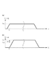
図6は、定着ローラ318aの周速度V1及び搬送ローラ318bの周速度V2を示すタイムチャートである。図6(a)は、定着ローラ318aの周速度V1を示す図である。また、図6(b)は、搬送ローラ318bの周速度V2を示す図である。
FIG. 6 is a time chart showing the peripheral speed V1 of the fixing
本実施形態では、搬送ローラ318bの周速度V2がVP2となるようにモータM2が制御され、定着ローラ318aの周速度V1がVP1となるようにモータM1が制御される。なお、搬送ローラ318bの周速度VP2は定着ローラ318aの周速度VP1よりもΔV大きい値である。即ち、搬送ローラ318bは定着ローラ318aよりもΔV速い周速度で回転する。
In the present embodiment, the motor M2 is controlled so that the peripheral speed V2 of the
このように、搬送ローラ318bの周速度が定着ローラ318aの周速度よりも速い周速度に設定されることによって、搬送ローラ318bと定着ローラ318aとの間で記録媒体が撓んでしまうことを防止することができる。この結果、搬送ローラ318bと定着ローラ318aとの間で記録媒体が撓むことに起因して定着後の記録媒体が定着ローラに接し、画像が乱れてしまうことを防止することができる。
In this way, by setting the peripheral speed of the
また、搬送ローラ318bの周速度が定着ローラ318aの周速度よりも速い周速度に設定されることによって、後述するように、シートを検出する精度が、搬送ローラ306と搬送ローラ307とが同じ周速度で回転する場合よりも向上する。なお、速度差ΔVは、周速度V1で回転する搬送ローラ307によって搬送されるシートの表面を搬送ローラ306がスリップしたとしてもシートに定着された画像にダメージが与えられないような速度差に設定される。なお、本実施形態においては、例えば、搬送されるシートの種類が厚紙である場合の周速差ΔVは薄紙である場合の周速差ΔVと同じ周速差である。
Further, by setting the peripheral speed of the
図7は、搬送ローラ318bを駆動するモータM2を制御するモータ制御装置157から出力された偏差Δθを示す図である。なお、図7においては、偏差Δθが負の値であることは回転位相θが指令位相θ_refよりも遅れていることを意味し、偏差Δθが正の値であることは回転位相θが指令位相θ_refよりも進んでいることを意味する。しかしながら、偏差Δθの極性と回転位相θ及び指令位相θ_refの関係は、これに限定されるわけではない。例えば、回転位相θが指令位相θ_refよりも遅れている場合は偏差Δθが正の値であり、回転位相θが指令位相θ_refよりも進んでいる場合は偏差Δθが負の値である構成でもよい。
FIG. 7 is a diagram showing a deviation Δθ output from the
本実施形態では、周速度VP1で回転する定着ローラ318aによってシートが搬送される。また、CPU151aは、予め決められた画像形成装置100の動作シーケンスによって設定された時刻t0で搬送ローラ318bの駆動を開始する。なお、定着ローラ318aの周速度VP1はシートが搬送される搬送速度である。また、搬送ローラ318bの周速度V2は、周速度VP1よりもΔV大きい周速度VP2に設定される。また、搬送ローラ318bの駆動が開始される時刻t0は、定着ローラ318aによって搬送されているシートの先端が搬送ローラ318bのニップ部に到達するまでに搬送ローラ318bの周速度がVP2に到達するように設定される。
In the present embodiment, the sheet is conveyed by the fixing
シートが搬送ローラ307と搬送ローラ306との両方によって搬送される際に搬送ローラ306にかかるトルクは、搬送ローラ306が搬送ローラ307と同じ周速度で回転する場合より搬送ローラ306が搬送ローラ307より速い周速度で回転する場合のほうが大きい。これは、搬送ローラ306が搬送ローラ307より速い周速度で回転する場合、搬送ローラ306は、搬送ローラ307にニップされているシートを下流側へ引っ張るからである。搬送ローラ306にかかる負荷トルクが大きくなると、搬送ローラ306を駆動するモータM2の回転子の回転位相θが指令位相θ_refよりも遅れることに起因して、偏差Δθの絶対値が大きくなる。具体的には、例えば、図7に示すように、搬送ローラ306によるシートの搬送が開始される(シートが搬送ローラ306にニップされる)時刻t1において、偏差Δθの絶対値は増大する。このように、搬送ローラ306を搬送ローラ307よりも速い速度で駆動させることによって、シートの先端が搬送ローラ306のニップ部にニップされるときの負荷トルクの変動幅を大きくさせることができる。
When the sheet is conveyed by both the
本実施形態においては、搬送ローラ318bによるシートの搬送が開始されたか(シートが搬送ローラ318bにニップされたか)否かを判定するための偏差Δθの閾値(所定値)として閾値Δθthが設定されている。
In the present embodiment, the threshold value Δθth is set as the threshold value (predetermined value) of the deviation Δθ for determining whether or not the sheet transfer by the
シート検出器700は、偏差Δθの絶対値が閾値Δθth以上になったか否かを判定する。シート検出器700は、偏差Δθの絶対値が閾値Δθth以上になると、搬送ローラ318bによるシートの搬送が開始された(シートが搬送ローラ318bにニップされた)ことを示す信号をCPU151aに検出結果として出力する。なお、シート検出器700は、偏差Δθの絶対値が閾値Δθth未満である場合、シートの先端が搬送ローラ318bのニップ部に到達していないことを示す信号をCPU151aに検出結果として出力する。
The
なお、本実施形態では、画像形成装置100において搬送され得るシートの種類のうち、当該シートが搬送される際に搬送ローラに生じる負荷変動が最も小さいシートの種類に基づいて閾値Δθthが設定される。具体的には、例えば、画像形成装置100において搬送され得るシートの種類が厚紙、普通紙、薄紙である場合、厚紙の先端が搬送される際に排紙ローラに生じる負荷変動は、普通紙や薄紙が搬送される際に排紙ローラに生じる負荷変動よりも大きい。また、普通紙が搬送される際に排紙ローラに生じる負荷変動は、薄紙が搬送される際に排紙ローラに生じる負荷変動よりも大きい。したがって、閾値Δθthは、薄紙が搬送される際に排紙ローラに生じる負荷変動に基づいて設定される。
In the present embodiment, among the types of sheets that can be conveyed by the
閾値Δθthは、例えば、搬送ローラ318bのニップ部に薄紙(シート)がニップされていない状態であって且つ搬送ローラ318bが定速回転している状態において想定される偏差Δθの絶対値より大きい値に設定される。また、閾値Δθthは、薄紙(シート)が定着ローラ318aと搬送ローラ318bとによって搬送されることによって増大する偏差Δθの絶対値の最大値(ピーク値)より小さい値に設定される。即ち、偏差Δθの絶対値が閾値Δθth以上になることは、シートの先端が搬送ローラ318bのニップ部に到達したことを意味する。
The threshold value Δθth is, for example, a value larger than the absolute value of the deviation Δθ assumed in a state where the thin paper (sheet) is not nipped in the nip portion of the
以上のように、本実施形態では、シートの搬送方向における下流側の搬送ローラ318bを上流側の定着ローラ318aよりも速い速度で駆動させる。この結果、シートの先端が搬送ローラ318bのニップ部にニップされるときの負荷トルクの変動幅を比較的大きくすることができる。その結果、シートの検出を高精度に行うことができる。
As described above, in the present embodiment, the
{シートが定着ローラに巻き付いたか否かを判定する方法}
図8は、搬送ローラ318bの制御方法を説明するフローチャートである。以下に、図8を用いて、搬送ローラ318bの制御について説明する。このフローチャートの処理は、CPU151aによって実行される。
{How to determine if the sheet is wrapped around the fixing roller}
FIG. 8 is a flowchart illustrating a control method of the
まず、CPU151aからモータ制御装置157にenable信号‘H’が出力されると、モータ制御装置157はCPU151aから出力される指令に基づいてモータM2の駆動を開始する。この結果、搬送ローラ318bの駆動が開始される。なお、enable信号とは、モータ制御装置157の稼働を許可又は禁止する信号である。enable信号が‘L(ローレベル)’である場合は、CPU151aはモータ制御装置157の稼働を禁止する。即ち、モータ制御装置157によるモータM2の制御は終了される。また、enable信号が‘H(ハイレベル)’である場合は、CPU151aはモータ制御装置157の稼働を許可して、モータ制御装置はCPU151aから出力される指令に基づいてモータM2の制御を行う。
First, when the enable signal ‘H’ is output from the
次に、S1001において、CPU151aは、定着ローラ318aの周速度がVP1で回転するようにモータM1を制御する指示をモータ制御装置158に出力する。この結果、モータ制御装置158は定着ローラ318aが周速度VP1で回転するようにモータM1を制御する。また、CPU151aは、搬送ローラ318bが定着ローラ318aの周速度VP1よりもΔV大きい周速度VP2で回転するようにモータM2を制御する指示をモータ制御装置157に出力する。この結果、モータ制御装置157は搬送ローラ318bが周速度VP2で回転するようにモータM2を制御する。
Next, in S1001, the
S1002において、偏差Δθの絶対値が閾値Δθthより小さい値から閾値Δθth以上の値に変化すると、即ち、シート検出器700からシートの先端が搬送ローラ318bのニップ部に到達したことを示す信号がCPU151aに入力されると、処理はS1003に進む。
In S1002, when the absolute value of the deviation Δθ changes from a value smaller than the threshold value Δθth to a value equal to or higher than the threshold value Δθth, that is, a signal indicating that the tip of the sheet has reached the nip portion of the
S1003において、印刷ジョブが終了する場合は、S1008において、CPU151aは搬送ローラ318b、定着ローラ318aの駆動を停止し、このフローチャートの処理を終了する。
When the print job ends in S1003, in S1008, the
また、S1002において、偏差Δθの絶対値が閾値Δθth未満である場合、即ち、シートの先端が搬送ローラ318bのニップ部に到達していないことを示す信号がシート検出器700からCPU151aに入力されると、処理はS1004に進む。
Further, in S1002, when the absolute value of the deviation Δθ is less than the threshold value Δθth, that is, a signal indicating that the tip of the sheet has not reached the nip portion of the
S1004において、レジストレーションローラ308が転写位置へのシートの搬送を開始してから所定時間T1が経過していない場合は、処理は再びS1002に戻る。
In S1004, if T1 has not elapsed for a predetermined time since the
また、S1004において、レジストレーションローラ308が転写位置へのシートの搬送を開始してから偏差Δθの絶対値が閾値Δθth1以上になることなく所定時間T1が経過した場合は、処理はS1005に進む。
Further, in S1004, if T1 elapses for a predetermined time without the absolute value of the deviation Δθ becoming equal to or greater than the threshold value Δθth1 after the
S1005において、CPU151aは、定着ヒータ161に電力を供給しないようにACドライバ160を制御する。この結果、定着ヒータ161による定着器の加熱が停止される。
In S1005, the
その後、S1006において、CPU151aは、定着ローラ318a及び搬送ローラ318bの駆動を停止する。
After that, in S1006, the
なお、所定時間T1は、レジストレーションローラ308が転写位置へのシートの搬送を開始するタイミングからシートが搬送ローラ318bのニップ部に到達するまでにかかる時間よりも長い時間である。更に、所定時間T1は、当該タイミングから、レジストレーションローラ308のニップ部から定着ローラ318aのニップ部までの距離と定着ローラ318aの円周の長さπ*Rとを足し合わせた距離シートが搬送されるまでの時間よりも短い時間である。
The predetermined time T1 is longer than the time required from the timing at which the
その後、S1007において、CPU151aは、シートの搬送に異常(例えば、定着ローラ318aへのシートの巻き付き、遅延ジャム等)が生じたことを、操作部152に設けられた表示部に表示してユーザに知らせる。このように、レジストレーションローラ308が転写位置へのシートの搬送を開始してから所定時間T1が経過したか否かが判断されることによって、シートが正常に搬送されているか否かを検出することができる。
After that, in S1007, the
以上のように、本実施形態では、フォトセンサ等のセンサではなくモータ制御装置157から出力される信号に基づいてシートの検出が行われる。この結果、画像形成装置の大型化及びコストの増大を抑制することができる。
As described above, in the present embodiment, the sheet is detected based on the signal output from the
また、本実施形態では、定着ローラ318aのニップ部から搬送ローラ318bのニップ部までの距離Lは、定着ローラ318aの円周の長さπ*R(Rは定着ローラの直径である)よりも短い値に設定される。また、レジストレーションローラ308が転写位置へのシートの搬送を開始してから偏差Δθの絶対値が閾値Δθthよりも小さい状態が所定時間T1継続すると、CPU151aは、定着ヒータへの電力供給の停止、定着ローラ318a及び搬送ローラ318bの駆動の停止を行う。そして、CPU151aは、シートの搬送に異常(例えば、定着ローラ318aへのシートの巻き付き、遅延ジャム等)が生じたことを、操作部152に設けられた表示部に表示してユーザに知らせる。この結果、記録媒体が貼り付いた定着ローラが1回転した後に当該記録媒体を定着ローラから取り除く場合よりも、容易に記録媒体を定着ローラから取り除くことができる。
Further, in the present embodiment, the distance L from the nip portion of the fixing
なお、本実施形態では、偏差Δθの絶対値が閾値Δθth未満である状態が、レジストレーションローラが転写位置へのシートの搬送を開始してから所定時間T1継続したら、定着ヒータへの電力供給が停止され、シートの搬送が停止されたが、この限りではない。例えば、偏差Δθの絶対値が閾値Δθth未満である状態が、シートが搬送ローラ318bの上流側の所定位置に到達してから所定時間継続したら、定着ヒータへの電力供給が停止され、シートの搬送が停止される構成でもよい。なお、所定時間は、シートが当該所定位置に到達するタイミングからシートが搬送ローラ318bのニップ部に到達するまでにかかる時間よりも長い時間である。更に、所定時間は、当該タイミングから、レジストレーションローラ308のニップ部から定着ローラ318aのニップ部までの距離と定着ローラ318aの円周の長さπ*Rとを足し合わせた距離シートが搬送されるまでの時間よりも短い時間である。
In the present embodiment, when the absolute value of the deviation Δθ is less than the threshold value Δθth and T1 continues for a predetermined time after the registration roller starts the transfer of the sheet to the transfer position, the power supply to the fixing heater is supplied. It was stopped and the sheet transfer was stopped, but this is not the case. For example, if the absolute value of the deviation Δθ is less than the threshold value Δθth and continues for a predetermined time after the sheet reaches a predetermined position on the upstream side of the
〔第2実施形態〕
画像形成装置100の構成が第1実施形態と同様である部分については説明を省略する。
[Second Embodiment]
The description of the portion where the configuration of the
第1実施形態では、搬送ローラ318bを駆動するモータは定着ローラ318aを駆動するモータとは異なるモータであった。即ち、第1実施形態では、搬送ローラ318b及び定着ローラ318aはそれぞれ独立して駆動され、搬送ローラ318bを駆動するモータに関する信号に基づいて、シートが定着ローラに巻き付いたか否かが判定された。
In the first embodiment, the motor for driving the
本実施形態では、搬送ローラ318bを駆動するモータが定着ローラ318aを駆動するモータと同じモータである構成において、シートが定着ローラに巻き付いたか否かが判定される方法について説明する。
In the present embodiment, in a configuration in which the motor for driving the
[定着器の構成]
図9は、本実施形態における定着器の構成を説明する図である。図9に示すように、定着ローラ318a及び搬送ローラ318bはモータM2によって駆動され、モータM2はモータ制御装置157によって制御される。
[Fuser configuration]
FIG. 9 is a diagram illustrating a configuration of a fuser in the present embodiment. As shown in FIG. 9, the fixing
本実施形態では、定着ローラ318aのニップ部から搬送ローラ318bのニップ部までの距離Lは、定着ローラ318aの円周の長さπ*R(Rは定着ローラの直径である)よりも短い値に設定される。
In the present embodiment, the distance L from the nip portion of the fixing
また、本実施形態では、定着ローラ318aのニップ部から搬送ローラ318bのニップ部までの距離Lは、画像形成装置100において搬送が許容されているシートのうち、搬送方向におけるシートの長さが最少であるシートの長さよりも短い値に設定される。
Further, in the present embodiment, the distance L from the nip portion of the fixing
シート検出器700は、第1実施形態において説明した方法により、シートの先端が搬送ローラ318bのニップ部に到達したか否かを検出し、検出結果をCPU151aに出力する。CPU151aは、当該検出結果に基づいて、シートが定着ローラに巻きついたか否かを判定する。
The
なお、本実施形態では、搬送ローラ318bの周速度V2が定着ローラ318aの周速度V1よりもΔV大きくなるように、例えば、ギア等でモータM2から搬送ローラ318bに伝達される回転力が調整される。
In this embodiment, the rotational force transmitted from the motor M2 to the
このように、搬送ローラ318bの周速度が定着ローラ318aの周速度よりも速い周速度に設定されることによって、搬送ローラ318bと定着ローラ318aとの間で記録媒体が撓んでしまうことを防止することができる。この結果、搬送ローラ318bと定着ローラ318aとの間で記録媒体が撓むことに起因して定着後の記録媒体が定着ローラに接し、画像が乱れてしまうことを防止することができる。
In this way, by setting the peripheral speed of the
また、搬送ローラ318bの周速度が定着ローラ318aの周速度よりも速い周速度に設定されることによって、第1実施形態において説明したように、シートを検出する精度が、搬送ローラ306と搬送ローラ307とが同じ周速度で回転する場合よりも向上する。
Further, by setting the peripheral speed of the
図10は、モータ制御装置157から出力された偏差Δθを示す図である。なお、図10においては、偏差Δθが負の値であることは回転位相θが指令位相θ_refよりも遅れていることを意味し、偏差Δθが正の値であることは回転位相θが指令位相θ_refよりも進んでいることを意味する。しかしながら、偏差Δθの極性と回転位相θ及び指令位相θ_refの関係は、これに限定されるわけではない。例えば、回転位相θが指令位相θ_refよりも遅れている場合は偏差Δθが正の値であり、回転位相θが指令位相θ_refよりも進んでいる場合は偏差Δθが負の値である構成でもよい。
FIG. 10 is a diagram showing a deviation Δθ output from the
本実施形態においては、定着ローラ318aによるシートの搬送が開始されたか(シートが定着ローラ318aにニップされたか)否かを判定するための偏差Δθの閾値として閾値Δθth1(所定値)が設定されている。また、搬送ローラ318bによるシートの搬送が開始されたか(シートが搬送ローラ318bにニップされたか)否かを判定するための偏差Δθの閾値として閾値Δθth2が設定されている。
In the present embodiment, a threshold value Δθth1 (predetermined value) is set as a threshold value of the deviation Δθ for determining whether or not the sheet transfer by the fixing
シート検出器700は、偏差Δθの絶対値が閾値Δθth1以上になったか否かを判定する。シート検出器700は、偏差Δθの絶対値が閾値Δθth1以上になると、定着ローラ318aによるシートの搬送が開始された(シートが定着ローラ318aにニップされた)ことを示す信号をCPU151aに検出結果として出力する。なお、シート検出器700は、偏差Δθの絶対値が閾値Δθth1未満である場合、シートの先端が定着ローラ318aのニップ部に到達していないことを示す信号をCPU151aに検出結果として出力する。
The
偏差Δθの絶対値が閾値Δθth1以上になると、次に、シート検出器700は偏差Δθの絶対値が閾値Δθth2以上になったか否かを判定する。シート検出器700は、偏差Δθの絶対値が閾値Δθth2以上になると、搬送ローラ318bによるシートの搬送が開始された(シートが搬送ローラ318bにニップされた)ことを示す信号をCPU151aに検出結果として出力する。なお、シート検出器700は、偏差Δθの絶対値が閾値Δθth2未満である場合、シートの先端が搬送ローラ318bのニップ部に到達していないことを示す信号をCPU151aに検出結果として出力する。
When the absolute value of the deviation Δθ becomes the threshold value Δθth1 or more, the
なお、本実施形態では、画像形成装置100において搬送され得るシートの種類のうち、当該シートが搬送される際に搬送ローラに生じる負荷変動が最も小さいシートの種類に基づいて閾値Δθth1及びΔθth2が設定される。具体的には、例えば、画像形成装置100において搬送され得るシートの種類が厚紙、普通紙、薄紙である場合、厚紙の先端が搬送される際に排紙ローラに生じる負荷変動は、普通紙や薄紙が搬送される際に排紙ローラに生じる負荷変動よりも大きい。また、普通紙が搬送される際に排紙ローラに生じる負荷変動は、薄紙が搬送される際に排紙ローラに生じる負荷変動よりも大きい。したがって、閾値Δθth1及びΔθth2は、薄紙が搬送される際に排紙ローラに生じる負荷変動に基づいて設定される。
In the present embodiment, the threshold values Δθth1 and Δθth2 are set based on the type of sheet that has the smallest load fluctuation generated in the transport roller when the sheet is transported among the types of sheets that can be transported by the
閾値Δθth1は、例えば、定着ローラ318aのニップ部に薄紙(シート)がニップされていない状態であって且つ定着ローラ318aが定速回転している状態において想定される偏差Δθの絶対値より大きい値に設定される。また、閾値Δθth1は、薄紙(シート)が定着ローラ318aのニップ部にシートがニップされることによって増大する偏差Δθの絶対値の最大値(ピーク値)より小さい値に設定される。即ち、偏差Δθの絶対値が閾値Δθth1以上になることは、シートの先端が定着ローラ318aのニップ部に到達したことを意味する。
The threshold value Δθth1 is, for example, a value larger than the absolute value of the deviation Δθ assumed in the state where the thin paper (sheet) is not nipped in the nip portion of the fixing
また、閾値Δθth2は、例えば、搬送ローラ318bのニップ部に薄紙(シート)がニップされていない状態であって且つ搬送ローラ318bが定速回転している状態において想定される偏差Δθの絶対値より大きい値に設定される。また、閾値Δθth2は、薄紙(シート)が定着ローラ318aと搬送ローラ318bとによって搬送されることによって増大する偏差Δθの絶対値の最大値(ピーク値)より小さい値に設定される。即ち、偏差Δθの絶対値が閾値Δθth2以上になることは、シートの先端が搬送ローラ318bのニップ部に到達したことを意味する。
Further, the threshold value Δθth2 is, for example, from the absolute value of the deviation Δθ assumed in the state where the thin paper (sheet) is not nipped in the nip portion of the
以上のように、本実施形態では、シートの搬送方向における下流側の搬送ローラ318bを上流側の定着ローラ318aよりも速い速度で駆動させる。この結果、シートの先端が搬送ローラ318bのニップ部にニップされるときの負荷トルクの変動幅を比較的大きくすることができる。その結果、シートの検出を高精度に行うことができる。
As described above, in the present embodiment, the
図11は、搬送ローラ318bの制御方法を説明するフローチャートである。以下に、図11を用いて、搬送ローラ318bの制御について説明する。このフローチャートの処理は、CPU151aによって実行される。
FIG. 11 is a flowchart illustrating a control method of the
まず、CPU151aからモータ制御装置157にenable信号‘H’が出力されると、モータ制御装置157はCPU151aから出力される指令に基づいてモータM2の駆動を開始する。この結果、搬送ローラ318bの駆動が開始される。なお、enable信号とは、モータ制御装置157の稼働を許可又は禁止する信号である。enable信号が‘L(ローレベル)’である場合は、CPU151aはモータ制御装置157の稼働を禁止する。即ち、モータ制御装置157によるモータM2の制御は終了される。また、enable信号が‘H(ハイレベル)’である場合は、CPU151aはモータ制御装置157の稼働を許可して、モータ制御装置はCPU151aから出力される指令に基づいてモータM2の制御を行う。
First, when the enable signal ‘H’ is output from the
次に、S2001において、CPU151aは、定着ローラ318a及び搬送ローラ318bが回転するようにモータM2を制御する指示をモータ制御装置157に出力する。この結果、モータ制御装置157は定着ローラ318a及び搬送ローラ318bが回転するようにモータM2を制御する。
Next, in S2001, the
S2002において、偏差Δθの絶対値が閾値Δθth1より小さい値から閾値Δθth1以上の値に変化すると、即ち、シート検出器700からシートの先端が定着ローラ318aのニップ部に到達したことを示す信号がCPU151aに入力されると、処理はS2003に進む。
In S2002, when the absolute value of the deviation Δθ changes from a value smaller than the threshold value Δθth1 to a value of the threshold value Δθth1 or more, that is, a signal indicating that the tip of the sheet has reached the nip portion of the fixing
S2003において、偏差Δθの絶対値が閾値Δθth2より小さい値から閾値Δθth2以上の値に変化すると、即ち、シート検出器700からシートの先端が搬送ローラ318bのニップ部に到達したことを示す信号がCPU151aに入力されると、処理はS2004に進む。
In S2003, when the absolute value of the deviation Δθ changes from a value smaller than the threshold value Δθth2 to a value of the threshold value Δθth2 or more, that is, a signal indicating that the tip of the sheet has reached the nip portion of the
S2004において、印刷ジョブが終了する場合は、S2005において、CPU151aは搬送ローラ318b、定着ローラ318aの駆動を停止し、このフローチャートの処理を終了する。
When the print job ends in S2004, the
また、S2003において、偏差Δθの絶対値が閾値Δθth2未満である場合、即ち、シートの先端が搬送ローラ318bのニップ部に到達していないことを示す信号がシート検出器700からCPU151aに入力されると、処理はS2006に進む。
Further, in S2003, when the absolute value of the deviation Δθ is less than the threshold value Δθth2, that is, a signal indicating that the tip of the sheet has not reached the nip portion of the
S2006において、偏差Δθの絶対値が閾値Δθth1以上になってから所定時間T2が経過していない場合は、処理は再びS2003に戻る。 In S2006, if the predetermined time T2 has not elapsed since the absolute value of the deviation Δθ becomes the threshold value Δθth1 or more, the process returns to S2003 again.
また、S2006において、偏差Δθの絶対値が閾値Δθth1以上になってから偏差Δθの絶対値が閾値Δθth2以上になることなく所定時間T2が経過した場合は、処理はS2007に進む。 Further, in S2006, if the predetermined time T2 elapses without the absolute value of the deviation Δθ becoming the threshold value Δθth2 or more after the absolute value of the deviation Δθ becomes the threshold value Δθth1 or more, the process proceeds to S2007.
S2007において、CPU151aは、定着ヒータ161に電力を供給しないようにACドライバ160を制御する。この結果、定着ヒータ161による定着器の加熱が停止される。
In S2007, the
その後、S2008において、CPU151aは、定着ローラ318a及び搬送ローラ318bの駆動を停止する。
After that, in S2008, the
なお、所定時間T2は、偏差Δθの絶対値が閾値Δθth1以上になってからシートが搬送ローラ318bのニップ部に到達するまでにかかる時間よりも長い時間である。更に、所定時間T2は、偏差Δθの絶対値が閾値Δθth1以上になってから定着ローラ318aの円周の長さπ*R分シートが搬送されるまでの時間よりも短い時間である。
The predetermined time T2 is longer than the time required for the sheet to reach the nip portion of the
その後、S2009において、CPU151aは、シートの搬送に異常(例えば、定着ローラ318aへのシートの巻き付き、遅延ジャム等)が生じたことを、操作部152に設けられた表示部に表示してユーザに知らせる。
After that, in S2009, the
また、S2002において、偏差Δθの絶対値が閾値Δθth1未満である場合、即ち、シートの先端が定着ローラ318aのニップ部に到達していないことを示す信号がシート検出器700からCPU151aに入力されると、処理はS2010に進む。
Further, in S2002, when the absolute value of the deviation Δθ is less than the threshold value Δθth1, that is, a signal indicating that the tip of the sheet has not reached the nip portion of the fixing
S2010において、レジストレーションローラ308が転写位置へのシートの搬送を開始してから所定時間T3が経過していない場合は、処理は再びS2002に戻る。
In S2010, if T3 has not elapsed for a predetermined time since the
また、S2010において、レジストレーションローラ308が転写位置へのシートの搬送を開始してから偏差Δθの絶対値が閾値Δθth1以上になることなく所定時間T3が経過した場合は、CPU151aは、処理をS2011に進める。
Further, in S2010, when the predetermined time T3 elapses without the absolute value of the deviation Δθ becoming equal to or greater than the threshold value Δθth1 after the
S2011において、CPU151aは、定着ヒータ161に電力を供給しないようにACドライバ160を制御する。この結果、定着ヒータ161による定着器の加熱が停止される。
In S2011, the
その後、S2012において、CPU151aは、定着ローラ318a及び搬送ローラ318bの駆動を停止する。
After that, in S2012, the
なお、所定時間T3は、レジストレーションローラ308が転写位置へのシートの搬送を開始するタイミングからシートが定着ローラ318aのニップ部に到達するまでにかかる時間よりも長い時間である。更に、所定時間T3は、当該タイミングからシートの先端が搬送ローラ318bのニップ部に到達するまでの時間よりも短い時間である。
The predetermined time T3 is longer than the time required from the timing at which the
その後、S2013において、CPU151aは、シートの搬送に異常(例えば、遅延ジャム)が生じたことを、操作部152に設けられた表示部に表示してユーザに知らせる。
After that, in S2013, the
以上のように、本実施形態では、フォトセンサ等のセンサではなくモータ制御装置157から出力される信号に基づいてシートの検出が行われる。この結果、画像形成装置の大型化及びコストの増大を抑制することができる。
As described above, in the present embodiment, the sheet is detected based on the signal output from the
また、本実施形態では、定着ローラ318aのニップ部から搬送ローラ318bのニップ部までの距離Lは、定着ローラ318aの円周の長さπ*R(Rは定着ローラの直径である)よりも短い値に設定される。
Further, in the present embodiment, the distance L from the nip portion of the fixing
レジストレーションローラ308が転写位置へのシートの搬送を開始してから偏差Δθの絶対値が閾値Δθth1よりも小さい状態が所定時間T3継続すると、CPU151aは、定着ヒータへの電力供給を停止し、定着ローラ318a及び搬送ローラ318bの駆動を停止する。そして、CPU151aは、シートの搬送に異常(例えば、遅延ジャム)が生じたことを、操作部152に設けられた表示部に表示してユーザに知らせる。この結果、記録媒体が貼り付いた定着ローラが1回転した後に当該記録媒体を定着ローラから取り除く場合よりも、容易に記録媒体を定着ローラから取り除くことができる。
When the state in which the absolute value of the deviation Δθ is smaller than the threshold value Δθth1 continues for T3 for a predetermined time after the
また、偏差Δθの絶対値が閾値Δθth1以上になってから偏差Δθの絶対値が閾値Δθth2よりも小さい状態が所定時間T2継続すると、CPU151aは、定着ヒータへの電力供給を停止し、定着ローラ318a及び搬送ローラ318bの駆動を停止する。そして、CPU151aは、シートの搬送に異常(例えば、定着ローラ318aへのシートの巻き付き、遅延ジャム等)が生じたことを、操作部152に設けられた表示部に表示してユーザに知らせる。この結果、記録媒体が貼り付いた定着ローラが1回転した後に当該記録媒体を定着ローラから取り除く場合よりも、容易に記録媒体を定着ローラから取り除くことができる。
Further, when the absolute value of the deviation Δθ becomes smaller than the threshold value Δθth1 and the state in which the absolute value of the deviation Δθ is smaller than the threshold value Δθth2 continues for T2 for a predetermined time, the
なお、第1実施形態及び第2実施形態では、レジストレーションローラ308が転写位置へのシートの搬送を開始してから偏差Δθの絶対値が閾値未満である状態が所定時間継続したら、定着ヒータへの電力供給が停止され、定着ローラ318a及び搬送ローラ318bの駆動が停止されたが、この限りではない。
In the first embodiment and the second embodiment, if the absolute value of the deviation Δθ is less than the threshold value for a predetermined time after the
なお、本実施形態では、偏差Δθの絶対値が閾値Δθth1未満である状態が、レジストレーションローラが転写位置へのシートの搬送を開始してから所定時間T3継続したら、定着ヒータへの電力供給が停止され、シートの搬送が停止されたが、この限りではない。例えば、偏差Δθの絶対値が閾値Δθth1未満である状態が、シートが搬送ローラ318bの上流側の所定位置に到達してから所定時間継続したら、定着ヒータへの電力供給が停止され、シートの搬送が停止される構成でもよい。なお、所定時間は、シートが当該所定位置に到達するタイミングからシートが搬送ローラ318bのニップ部に到達するまでにかかる時間よりも長い時間である。更に、所定時間は、当該タイミングから、レジストレーションローラ308のニップ部から定着ローラ318aのニップ部までの距離と定着ローラ318aの円周の長さπ*Rとを足し合わせた距離シートが搬送されるまでの時間よりも短い時間である。
In the present embodiment, when the absolute value of the deviation Δθ is less than the threshold value Δθth1 and T3 continues for a predetermined time after the registration roller starts the transfer of the sheet to the transfer position, the power supply to the fixing heater is supplied. It was stopped and the sheet transfer was stopped, but this is not the case. For example, if the absolute value of the deviation Δθ is less than the threshold value Δθth1 and continues for a predetermined time after the sheet reaches a predetermined position on the upstream side of the
第1実施形態及び第2実施形態におけるシート検出器700の機能をCPU151aが有する構成であってもよい。
The
また、第1実施形態及び第2実施形態においては、周速差ΔVは、搬送されるシートの種類(紙種)に拘わらず所定の値に設定されたが、この限りではない。例えば、ユーザによって設定された紙種に応じて周速差ΔVが設定されてもよい。なお、厚紙に対応する周速差ΔVは薄紙に対応する周速差ΔV及び普通紙に対応する周速差ΔVより小さくてもよい。また、普通紙に対応する周速差ΔVは薄紙に対応する周速差ΔVより小さくてもよい。 Further, in the first embodiment and the second embodiment, the peripheral speed difference ΔV is set to a predetermined value regardless of the type (paper type) of the sheet to be conveyed, but the present invention is not limited to this. For example, the peripheral speed difference ΔV may be set according to the paper type set by the user. The peripheral speed difference ΔV corresponding to the thick paper may be smaller than the peripheral speed difference ΔV corresponding to the thin paper and the peripheral speed difference ΔV corresponding to the plain paper. Further, the peripheral speed difference ΔV corresponding to plain paper may be smaller than the peripheral speed difference ΔV corresponding to thin paper.
また、第1実施形態及び第2実施形態においては、紙種に拘わらず偏差Δθの閾値Δθthは所定の値であったが、閾値Δθthは紙種ごとに設定されてもよい。 Further, in the first embodiment and the second embodiment, the threshold value Δθth of the deviation Δθ is a predetermined value regardless of the paper type, but the threshold value Δθth may be set for each paper type.
また、第1実施形態及び第2実施形態においては、搬送ローラ318bの駆動が開始される時刻t0は、画像形成装置100の動作シーケンスによって予め定められているが、この限りではない。例えば、CPU151aからモータ制御装置に出力されるパルス数に基づいて搬送ローラ306の駆動が開始される構成であってもよい。
Further, in the first embodiment and the second embodiment, the time t0 at which the driving of the
また、第1実施形態及び第2実施形態においては、偏差Δθに基づいてシートの検出が行われたが、この限りではない。例えば、座標変換器511から出力される電流値iqの変化に基づいてシートの検出が行われてもよい。具体的には、例えば、電流値iqが閾値Δθthに対応する閾値iqthより大きくなったら、シートの先端が搬送ローラ306のニップ部に到達したと判断される構成であってもよい。なお、指令位相θ_refと位相決定器513によって決定された回転位相θとの偏差に基づいて決定されたq軸電流指令値(目標値)iq_refの変化に基づいてシートの検出が行われてもよい。また、静止座標系の電流値iα又はiβの振幅(大きさ)の変化に基づいてシートの検出が行われてもよい。
Further, in the first embodiment and the second embodiment, the sheet is detected based on the deviation Δθ, but this is not the case. For example, the sheet may be detected based on the change in the current value iq output from the coordinate
なお、電流値iq、電流値iq_ref及び静止座標系の電流値iα又はiβの振幅は、本発明におけるモータの回転子にかかる負荷トルクに対応するパラメータに対応する。 The amplitudes of the current value iq, the current value iq_ref, and the current value iα or iβ in the rest coordinate system correspond to the parameters corresponding to the load torque applied to the rotor of the motor in the present invention.
また、第1実施形態及び第2実施形態においては、下流側の搬送ローラを駆動するモータの回転速度が制御されることによって、下流側の搬送ローラと上流側の搬送ローラとの周速度に差がつけられたが、この限りではない。例えば、上流側の搬送ローラを駆動するモータの回転速度が制御されることによって、下流側の搬送ローラと上流側の搬送ローラとの周速度に差がつけられてもよい。また、上流側の搬送ローラを駆動するモータと下流側の搬送ローラを駆動するモータとの両方の回転速度が制御されることによって、下流側の搬送ローラと上流側の搬送ローラとの周速度に差がつけられてもよい。 Further, in the first embodiment and the second embodiment, the rotational speed of the motor that drives the transport roller on the downstream side is controlled, so that the peripheral speed between the transport roller on the downstream side and the transport roller on the upstream side is different. Was added, but this is not the case. For example, by controlling the rotation speed of the motor that drives the transport roller on the upstream side, the peripheral speed between the transport roller on the downstream side and the transport roller on the upstream side may be different. In addition, by controlling the rotation speeds of both the motor that drives the upstream transfer roller and the motor that drives the downstream transfer roller, the peripheral speed between the downstream transfer roller and the upstream transfer roller can be adjusted. A difference may be made.
第1実施形態及び第2実施形態が適用されるのは、ベクトル制御によるモータ制御に限らない。例えば、回転位相や回転速度をフィードバックする構成を有するモータ制御装置であれば本実施形態は適用される。 The first embodiment and the second embodiment are not limited to motor control by vector control. For example, the present embodiment is applied to a motor control device having a configuration for feeding back a rotation phase and a rotation speed.
第1実施形態及び第2実施形態における感光ドラム309、転写帯電器315等は画像形成手段に対応する。
The photosensitive drum 309, the
また、第1実施形態及び第2実施形態では、画像を熱によってシートに定着させる回転体として定着ローラ318aが用いられているが、例えば、回転体として定着ベルトが用いられてもよい。
Further, in the first embodiment and the second embodiment, the fixing
また、第1実施形態及び第2実施形態においては、負荷を駆動するモータとしてステッピングモータが用いられているが、DCモータ等の他のモータであっても良い。また、モータは2相モータである場合に限らず、3相モータ等の他のモータであっても第1実施形態、第2実施形態を適用することができる。 Further, in the first embodiment and the second embodiment, the stepping motor is used as the motor for driving the load, but other motors such as a DC motor may be used. Further, the motor is not limited to the case of a two-phase motor, and the first embodiment and the second embodiment can be applied to other motors such as a three-phase motor.
また、第1実施形態及び第2実施形態におけるベクトル制御では、位相フィードバック制御を行うことによってモータを制御しているが、これに限定されるものではない。例えば、回転子402の回転速度ωをフィードバックしてモータを制御する構成であっても良い。具体的には、図12に示すように、モータ制御装置内部に速度決定器514を設け、速度決定器514が位相決定器513から出力された回転位相θの所定期間における変化量に基づいて回転速度ωを決定する。なお、速度の決定には、以下の式(10)が用いられるものとする。
ω=dθ/dt (10)
Further, in the vector control in the first embodiment and the second embodiment, the motor is controlled by performing the phase feedback control, but the present invention is not limited to this. For example, the motor may be controlled by feeding back the rotation speed ω of the
ω = dθ / dt (10)
そして、CPU151aは回転子の目標速度を表す指令速度ω_refを出力する。更に、モータ制御装置内部に速度制御器500を設け、速度制御器500が回転速度ωと指令速度ω_refとの偏差が小さくなるように、q軸電流指令値iq_ref及びd軸電流指令値id_refを生成して出力する構成とする。このような速度フィードバック制御を行うことによって、モータを制御する構成であっても良い。このような構成の場合、シートの検知は、例えば、回転速度ωと指令速度ω_refとの偏差Δωに基づいて、本実施形態において説明した方法で行われる。なお、指令速度ω_refは、搬送ローラ306の周速度の目標速度に対応するモータM2の回転子の目標速度である。
Then, the
また、第1実施形態及び第2実施形態においては、回転子として永久磁石が用いられているが、これに限定されるものではない。 Further, in the first embodiment and the second embodiment, a permanent magnet is used as the rotor, but the present invention is not limited to this.
151a CPU
157 モータ制御装置
309 感光ドラム
315 転写帯電器
318 定着器
318a 定着ローラ
318b 搬送ローラ
402 回転子
502 位相制御器
513 位相決定器
700 シート検出器
M1、M2 ステッピングモータ
151a CPU
157 Motor control device 309
Claims (13)
ヒータと回転体とを備え、前記回転体によって前記シートを搬送しながら、前記画像形成手段によって当該シートに形成された前記画像を前記ヒータの熱によって当該シートに定着させる定着手段と、
前記回転体に隣接し且つ前記シートが搬送される搬送方向において前記回転体よりも下流側に設けられ、前記シートを搬送する搬送ローラと、
前記搬送ローラを駆動するモータと、
前記モータの回転子の回転位相を決定する位相決定手段と、
前記モータの回転子の目標位相を表す指令位相と前記位相決定手段によって決定された前記回転子の回転位相との偏差が小さくなるように、前記モータの巻線に流れる駆動電流を制御する第1制御手段と、
前記シートの搬送を制御する第2制御手段と、
前記モータの回転子にかかる負荷トルクに対応するパラメータの値の絶対値が所定値を超えると所定の信号を出力する出力手段と、
を有し、
前記回転体のニップ部から前記搬送ローラのニップ部までの距離は、前記回転体の周長よりも短く、
前記制御手段は、前記回転体と前記搬送ローラとが異なる速度で回転するように前記モータの巻線に流れる駆動電流を制御し、
前記第2制御手段は、前記シートの先端が前記回転体のニップ部よりも上流側の所定位置に到達してから所定時間が経過するまでの期間に前記所定の信号が前記出力手段から出力されない場合は前記シートの搬送を停止し、前記期間に前記所定の信号が前記出力手段から出力された場合は前記シートの搬送を継続し、
前記所定時間は、前記所定位置に到達した前記シートの先端が前記搬送ローラのニップ部に到達するのに要する時間よりも長く、且つ、前記所定位置に到達した前記シートの先端が、前記回転体のニップ部から前記搬送方向において前記回転体の周長分下流側の位置に到達するのに要する時間よりも短いことを特徴とする画像形成装置。 An image forming means for forming an image on a sheet,
A heater with a rotating body, while conveying the sheet by said rotary member, and a fixing means for fixing to the sheet the image formed on the sheet by the heat of the heater by said image forming means,
A transport roller adjacent to the rotating body and provided on the downstream side of the rotating body in the transport direction in which the sheet is transported, and a transport roller for transporting the sheet.
The motor that drives the transfer roller and
A phase determining means for determining the rotational phase of the rotor of the motor,
A first that controls the drive current flowing through the winding of the motor so that the deviation between the command phase representing the target phase of the rotor of the motor and the rotation phase of the rotor determined by the phase determining means becomes small. Control means and
A second control means for controlling the transfer of the sheet,
An output means that outputs a predetermined signal when the absolute value of the parameter value corresponding to the load torque applied to the rotor of the motor exceeds a predetermined value.
Have,
The distance from the nip portion of the rotating body to the nip portion of the transport roller is shorter than the peripheral length of the rotating body.
The control means controls the drive current flowing through the winding of the motor so that the rotating body and the transport roller rotate at different speeds.
The second control means does not output the predetermined signal from the output means during the period from when the tip of the sheet reaches the predetermined position on the upstream side of the nip portion of the rotating body until the predetermined time elapses. In that case, the transfer of the sheet is stopped, and when the predetermined signal is output from the output means during the period, the transfer of the sheet is continued.
The predetermined time is longer than the time required for the tip of the sheet that has reached the predetermined position to reach the nip portion of the transport roller, and the tip of the sheet that has reached the predetermined position is the rotating body. An image forming apparatus characterized in that it is shorter than the time required to reach a position on the downstream side by the peripheral length of the rotating body from the nip portion of the rotating body in the transport direction.
ヒータと回転体とを備え、前記回転体によって前記シートを搬送しながら、前記画像形成手段によって当該シートに形成された前記画像を前記ヒータの熱によって当該シートに定着させる定着手段と、
前記回転体に隣接し且つ前記シートが搬送される搬送方向において前記回転体よりも下流側に設けられ、前記シートを搬送する搬送ローラと、
前記搬送ローラを駆動するモータと、
前記モータの回転子の回転速度を決定する速度決定手段と、
前記モータの回転子の目標速度を表す指令速度と前記速度決定手段によって決定された前記回転子の回転速度との偏差が小さくなるように、前記モータの巻線に流れる駆動電流を制御する第1制御手段と、
前記シートの搬送を制御する第2制御手段と、
前記モータの回転子にかかる負荷トルクに対応するパラメータの値の絶対値が所定値を超えると所定の信号を出力する出力手段と、
を有し、
前記回転体のニップ部から前記搬送ローラのニップ部までの距離は、前記回転体の周長よりも短く、
前記制御手段は、前記回転体と前記搬送ローラとが異なる速度で回転するように前記モータの巻線に流れる駆動電流を制御し、
前記第2制御手段は、前記シートの先端が前記回転体のニップ部よりも上流側の所定位置に到達してから所定時間が経過するまでの期間に前記所定の信号が前記出力手段から出力されない場合は前記シートの搬送を停止し、前記期間に前記所定の信号が前記出力手段から出力された場合は前記シートの搬送を継続し、
前記所定時間は、前記所定位置に到達した前記シートの先端が前記搬送ローラのニップ部に到達するのに要する時間よりも長く、且つ、前記所定位置に到達した前記シートの先端が、前記回転体のニップ部から前記搬送方向において前記回転体の周長分下流側の位置に到達するのに要する時間よりも短いことを特徴とする画像形成装置。 An image forming means for forming an image on a sheet,
A heater with a rotating body, while conveying the sheet by said rotary member, and a fixing means for fixing to the sheet the image formed on the sheet by the heat of the heater by said image forming means,
A transport roller adjacent to the rotating body and provided on the downstream side of the rotating body in the transport direction in which the sheet is transported, and a transport roller for transporting the sheet.
The motor that drives the transfer roller and
A speed determining means for determining the rotational speed of the rotor of the motor,
A first that controls the drive current flowing through the winding of the motor so that the deviation between the command speed representing the target speed of the rotor of the motor and the rotation speed of the rotor determined by the speed determining means becomes small. Control means and
A second control means for controlling the transfer of the sheet,
An output means that outputs a predetermined signal when the absolute value of the parameter value corresponding to the load torque applied to the rotor of the motor exceeds a predetermined value.
Have,
The distance from the nip portion of the rotating body to the nip portion of the transport roller is shorter than the peripheral length of the rotating body.
The control means controls the drive current flowing through the winding of the motor so that the rotating body and the transport roller rotate at different speeds.
The second control means does not output the predetermined signal from the output means during the period from when the tip of the sheet reaches the predetermined position on the upstream side of the nip portion of the rotating body until the predetermined time elapses. In that case, the transfer of the sheet is stopped, and when the predetermined signal is output from the output means during the period, the transfer of the sheet is continued.
The predetermined time is longer than the time required for the tip of the sheet that has reached the predetermined position to reach the nip portion of the transport roller, and the tip of the sheet that has reached the predetermined position is the rotating body. An image forming apparatus characterized in that it is shorter than the time required to reach a position on the downstream side by the peripheral length of the rotating body from the nip portion of the rotating body in the transport direction.
前記第2制御手段は、前記期間に前記所定の信号が前記出力手段から出力されない場合は前記ヒータへの電力の供給を停止することを特徴とする請求項1乃至3のいずれか一項に記載の画像形成装置。 The second control means controls the supply of electric power to the heater, and the second control means controls the supply of electric power.
The second control means according to any one of claims 1 to 3, wherein the supply of electric power to the heater is stopped when the predetermined signal is not output from the output means during the period. Image forming device.
前記出力手段は、前記負荷トルクに対応するパラメータの値の絶対値が前記所定値より小さい第2の所定値より小さい値から前記第2の所定値より大きい値に変化した後に、前記負荷トルクに対応するパラメータの値の絶対値が前記所定値より小さい値から前記所定値より大きい値に変化すると、前記所定の信号を出力することを特徴とする請求項1乃至5のいずれか一項に記載の画像形成装置。 The motor drives the transport roller and the rotating body.
The output means obtains the load torque after the absolute value of the parameter value corresponding to the load torque changes from a value smaller than the second predetermined value smaller than the predetermined value to a value larger than the second predetermined value. The invention according to any one of claims 1 to 5 , wherein when the absolute value of the value of the corresponding parameter changes from a value smaller than the predetermined value to a value larger than the predetermined value, the predetermined signal is output. Image forming device.
前記制御手段は、前記位相決定手段によって決定された前記回転子の回転位相を基準とした回転座標系において表される、前記回転子にトルクを発生させるトルク電流成分に基づいて、前記巻線に流れる駆動電流を制御し、
前記負荷トルクに対応するパラメータは前記検出手段によって検出された前記駆動電流の前記トルク電流成分の値であることを特徴とする請求項1又は請求項1を引用する請求項3乃至8のいずれか一項に記載の画像形成装置。 The image forming apparatus has a detecting means for detecting a drive current flowing through the winding.
The control means applies to the winding based on a torque current component that generates torque in the rotor, which is represented in a rotating coordinate system based on the rotation phase of the rotor determined by the phase determining means. Control the flowing drive current,
One of claims 1 or any of claims 3 to 8 quoting claim 1, wherein the parameter corresponding to the load torque is a value of the torque current component of the drive current detected by the detection means. The image forming apparatus according to claim 1.
前記負荷トルクに対応するパラメータは前記トルク電流成分の目標値であることを特徴とする請求項1又は請求項1を引用する請求項3乃至8のいずれか一項に記載の画像形成装置。 The control means applies to the winding based on a torque current component that generates torque in the rotor, which is represented in a rotating coordinate system based on the rotation phase of the rotor determined by the phase determining means. Control the flowing drive current,
The image forming apparatus according to claim 1, wherein the parameter corresponding to the load torque is a target value of the torque current component, or any one of claims 3 to 8 quoting claim 1.
前記回転子の回転位相を決定する位相決定手段と、
前記巻線に流れる駆動電流を検出する検出手段を有し、
前記制御手段は、前記位相決定手段によって決定された前記回転子の回転位相を基準とした回転座標系において表される、前記回転子にトルクを発生させるトルク電流成分に基づいて、前記巻線に流れる駆動電流を制御し、
前記負荷トルクに対応するパラメータは前記検出手段によって検出された前記駆動電流の前記トルク電流成分の値であることを特徴とする請求項2又は請求項2を引用する請求項3乃至8のいずれか一項に記載の画像形成装置。 The image forming apparatus is
A phase determining means for determining the rotational phase of the rotor and
It has a detecting means for detecting the drive current flowing through the winding.
The control means applies to the winding based on a torque current component that generates torque in the rotor, which is represented in a rotating coordinate system based on the rotation phase of the rotor determined by the phase determining means. Control the flowing drive current,
Any one of claims 3 to 8 parameters corresponding to the load torque cites claim 2 or claim 2, characterized in that the value of the torque current component of the driving current detected by said detecting means The image forming apparatus according to claim 1.
前記制御手段は、前記位相決定手段によって決定された前記回転子の回転位相を基準とした回転座標系において表される、前記回転子にトルクを発生させるトルク電流成分に基づいて、前記巻線に流れる駆動電流を制御し、
前記負荷トルクに対応するパラメータは前記トルク電流成分の目標値であることを特徴とする請求項2又は請求項2を引用する請求項3乃至8のいずれか一項に記載の画像形成装置。 The image forming apparatus has a phase determining means for determining the rotational phase of the rotor.
The control means applies to the winding based on a torque current component that generates torque in the rotor, which is represented in a rotating coordinate system based on the rotation phase of the rotor determined by the phase determining means. Control the flowing drive current,
The image forming apparatus according to any one of claims 3 to 8 , wherein the parameter corresponding to the load torque is a target value of the torque current component.
Priority Applications (1)
| Application Number | Priority Date | Filing Date | Title |
|---|---|---|---|
| JP2017230995A JP6968674B2 (en) | 2017-11-30 | 2017-11-30 | Image forming device |
Applications Claiming Priority (1)
| Application Number | Priority Date | Filing Date | Title |
|---|---|---|---|
| JP2017230995A JP6968674B2 (en) | 2017-11-30 | 2017-11-30 | Image forming device |
Publications (3)
| Publication Number | Publication Date |
|---|---|
| JP2019101190A JP2019101190A (en) | 2019-06-24 |
| JP2019101190A5 JP2019101190A5 (en) | 2020-12-03 |
| JP6968674B2 true JP6968674B2 (en) | 2021-11-17 |
Family
ID=66973515
Family Applications (1)
| Application Number | Title | Priority Date | Filing Date |
|---|---|---|---|
| JP2017230995A Active JP6968674B2 (en) | 2017-11-30 | 2017-11-30 | Image forming device |
Country Status (1)
| Country | Link |
|---|---|
| JP (1) | JP6968674B2 (en) |
Family Cites Families (3)
| Publication number | Priority date | Publication date | Assignee | Title |
|---|---|---|---|---|
| JP3252501B2 (en) * | 1992-12-02 | 2002-02-04 | キヤノン株式会社 | Image forming device |
| JP2003248392A (en) * | 2002-02-25 | 2003-09-05 | Canon Inc | Image forming apparatus |
| JP6704868B2 (en) * | 2016-05-09 | 2020-06-03 | キヤノン株式会社 | Sheet conveying device, original reading device and image forming apparatus including the sheet conveying device |
-
2017
- 2017-11-30 JP JP2017230995A patent/JP6968674B2/en active Active
Also Published As
| Publication number | Publication date |
|---|---|
| JP2019101190A (en) | 2019-06-24 |
Similar Documents
| Publication | Publication Date | Title |
|---|---|---|
| JP6505155B2 (en) | Motor control device, sheet conveying device, and image forming apparatus | |
| US10439531B2 (en) | Sheet conveying apparatus and image forming apparatus | |
| JP6647262B2 (en) | Motor control device, sheet transport device, document reading device, and image forming device | |
| JP6552532B2 (en) | Sheet conveying apparatus and image forming apparatus | |
| JP6991758B2 (en) | Sheet transfer device and image forming device | |
| JP7080700B2 (en) | Motor control device, sheet transfer device and image forming device | |
| JP6980555B2 (en) | Motor control device, sheet transfer device and image forming device | |
| JP6632642B2 (en) | Sheet conveying device and image forming device | |
| JP6776418B2 (en) | Sheet transfer device and image forming device | |
| JP6968674B2 (en) | Image forming device | |
| JP6720046B2 (en) | Motor control device, sheet conveying device, document reading device, and image forming device | |
| JP2020078236A (en) | Motor control device, sheet conveying device, document reading device, and image forming apparatus | |
| JP6849637B2 (en) | Sheet transfer device, document reader and image forming device | |
| JP6580180B2 (en) | Sheet conveying apparatus and image forming apparatus | |
| JP2020138811A (en) | Sheet transport device and image forming device | |
| JP7034727B2 (en) | Motor control device, sheet transfer device and image forming device | |
| JP6812505B2 (en) | Sheet transfer device, document feeding device, document reading device and image forming device | |
| JP2019104552A (en) | Sheet conveying equipment and image forming device | |
| JP7233987B2 (en) | image forming device | |
| JP7005733B2 (en) | Motor control device, sheet transfer device, and image forming device | |
| JP6849729B2 (en) | Motor control device, sheet transfer device and image forming device | |
| JP2018087076A (en) | Sheet conveying device | |
| JP2018076154A (en) | Image forming apparatus | |
| JP2019071731A (en) | Sheet transfer device and image formation device | |
| JP2020079130A (en) | Manuscript feeding device, manuscript reading device and image formation device |
Legal Events
| Date | Code | Title | Description |
|---|---|---|---|
| A521 | Written amendment |
Free format text: JAPANESE INTERMEDIATE CODE: A523 Effective date: 20201009 |
|
| A621 | Written request for application examination |
Free format text: JAPANESE INTERMEDIATE CODE: A621 Effective date: 20201009 |
|
| A977 | Report on retrieval |
Free format text: JAPANESE INTERMEDIATE CODE: A971007 Effective date: 20210830 |
|
| TRDD | Decision of grant or rejection written | ||
| A01 | Written decision to grant a patent or to grant a registration (utility model) |
Free format text: JAPANESE INTERMEDIATE CODE: A01 Effective date: 20210928 |
|
| A61 | First payment of annual fees (during grant procedure) |
Free format text: JAPANESE INTERMEDIATE CODE: A61 Effective date: 20211027 |
|
| R151 | Written notification of patent or utility model registration |
Ref document number: 6968674 Country of ref document: JP Free format text: JAPANESE INTERMEDIATE CODE: R151 |