JP6980555B2 - Motor control device, sheet transfer device and image forming device - Google Patents
Motor control device, sheet transfer device and image forming device Download PDFInfo
- Publication number
- JP6980555B2 JP6980555B2 JP2018026352A JP2018026352A JP6980555B2 JP 6980555 B2 JP6980555 B2 JP 6980555B2 JP 2018026352 A JP2018026352 A JP 2018026352A JP 2018026352 A JP2018026352 A JP 2018026352A JP 6980555 B2 JP6980555 B2 JP 6980555B2
- Authority
- JP
- Japan
- Prior art keywords
- phase
- motor
- control
- control mode
- command
- Prior art date
- Legal status (The legal status is an assumption and is not a legal conclusion. Google has not performed a legal analysis and makes no representation as to the accuracy of the status listed.)
- Active
Links
Images


Classifications
-
- H—ELECTRICITY
- H02—GENERATION; CONVERSION OR DISTRIBUTION OF ELECTRIC POWER
- H02P—CONTROL OR REGULATION OF ELECTRIC MOTORS, ELECTRIC GENERATORS OR DYNAMO-ELECTRIC CONVERTERS; CONTROLLING TRANSFORMERS, REACTORS OR CHOKE COILS
- H02P21/00—Arrangements or methods for the control of electric machines by vector control, e.g. by control of field orientation
- H02P21/22—Current control, e.g. using a current control loop
-
- G—PHYSICS
- G03—PHOTOGRAPHY; CINEMATOGRAPHY; ANALOGOUS TECHNIQUES USING WAVES OTHER THAN OPTICAL WAVES; ELECTROGRAPHY; HOLOGRAPHY
- G03G—ELECTROGRAPHY; ELECTROPHOTOGRAPHY; MAGNETOGRAPHY
- G03G15/00—Apparatus for electrographic processes using a charge pattern
- G03G15/50—Machine control of apparatus for electrographic processes using a charge pattern, e.g. regulating differents parts of the machine, multimode copiers, microprocessor control
- G03G15/5004—Power supply control, e.g. power-saving mode, automatic power turn-off
-
- G—PHYSICS
- G03—PHOTOGRAPHY; CINEMATOGRAPHY; ANALOGOUS TECHNIQUES USING WAVES OTHER THAN OPTICAL WAVES; ELECTROGRAPHY; HOLOGRAPHY
- G03G—ELECTROGRAPHY; ELECTROPHOTOGRAPHY; MAGNETOGRAPHY
- G03G15/00—Apparatus for electrographic processes using a charge pattern
- G03G15/65—Apparatus which relate to the handling of copy material
- G03G15/6502—Supplying of sheet copy material; Cassettes therefor
- G03G15/6508—Automatic supply devices interacting with the rest of the apparatus, e.g. selection of a specific cassette
-
- G—PHYSICS
- G03—PHOTOGRAPHY; CINEMATOGRAPHY; ANALOGOUS TECHNIQUES USING WAVES OTHER THAN OPTICAL WAVES; ELECTROGRAPHY; HOLOGRAPHY
- G03G—ELECTROGRAPHY; ELECTROPHOTOGRAPHY; MAGNETOGRAPHY
- G03G15/00—Apparatus for electrographic processes using a charge pattern
- G03G15/80—Details relating to power supplies, circuits boards, electrical connections
-
- H—ELECTRICITY
- H02—GENERATION; CONVERSION OR DISTRIBUTION OF ELECTRIC POWER
- H02P—CONTROL OR REGULATION OF ELECTRIC MOTORS, ELECTRIC GENERATORS OR DYNAMO-ELECTRIC CONVERTERS; CONTROLLING TRANSFORMERS, REACTORS OR CHOKE COILS
- H02P21/00—Arrangements or methods for the control of electric machines by vector control, e.g. by control of field orientation
- H02P21/14—Estimation or adaptation of machine parameters, e.g. flux, current or voltage
- H02P21/18—Estimation of position or speed
-
- H—ELECTRICITY
- H02—GENERATION; CONVERSION OR DISTRIBUTION OF ELECTRIC POWER
- H02P—CONTROL OR REGULATION OF ELECTRIC MOTORS, ELECTRIC GENERATORS OR DYNAMO-ELECTRIC CONVERTERS; CONTROLLING TRANSFORMERS, REACTORS OR CHOKE COILS
- H02P21/00—Arrangements or methods for the control of electric machines by vector control, e.g. by control of field orientation
- H02P21/24—Vector control not involving the use of rotor position or rotor speed sensors
-
- H—ELECTRICITY
- H02—GENERATION; CONVERSION OR DISTRIBUTION OF ELECTRIC POWER
- H02P—CONTROL OR REGULATION OF ELECTRIC MOTORS, ELECTRIC GENERATORS OR DYNAMO-ELECTRIC CONVERTERS; CONTROLLING TRANSFORMERS, REACTORS OR CHOKE COILS
- H02P8/00—Arrangements for controlling dynamo-electric motors of the kind having motors rotating step by step
- H02P8/12—Control or stabilisation of current
-
- H—ELECTRICITY
- H04—ELECTRIC COMMUNICATION TECHNIQUE
- H04N—PICTORIAL COMMUNICATION, e.g. TELEVISION
- H04N1/00—Scanning, transmission or reproduction of documents or the like, e.g. facsimile transmission; Details thereof
-
- G—PHYSICS
- G03—PHOTOGRAPHY; CINEMATOGRAPHY; ANALOGOUS TECHNIQUES USING WAVES OTHER THAN OPTICAL WAVES; ELECTROGRAPHY; HOLOGRAPHY
- G03G—ELECTROGRAPHY; ELECTROPHOTOGRAPHY; MAGNETOGRAPHY
- G03G15/00—Apparatus for electrographic processes using a charge pattern
- G03G15/65—Apparatus which relate to the handling of copy material
- G03G15/6529—Transporting
-
- G—PHYSICS
- G03—PHOTOGRAPHY; CINEMATOGRAPHY; ANALOGOUS TECHNIQUES USING WAVES OTHER THAN OPTICAL WAVES; ELECTROGRAPHY; HOLOGRAPHY
- G03G—ELECTROGRAPHY; ELECTROPHOTOGRAPHY; MAGNETOGRAPHY
- G03G2215/00—Apparatus for electrophotographic processes
- G03G2215/00362—Apparatus for electrophotographic processes relating to the copy medium handling
- G03G2215/00535—Stable handling of copy medium
- G03G2215/00611—Detector details, e.g. optical detector
- G03G2215/00632—Electric detector, e.g. of voltage or current
-
- G—PHYSICS
- G03—PHOTOGRAPHY; CINEMATOGRAPHY; ANALOGOUS TECHNIQUES USING WAVES OTHER THAN OPTICAL WAVES; ELECTROGRAPHY; HOLOGRAPHY
- G03G—ELECTROGRAPHY; ELECTROPHOTOGRAPHY; MAGNETOGRAPHY
- G03G2215/00—Apparatus for electrophotographic processes
- G03G2215/00362—Apparatus for electrophotographic processes relating to the copy medium handling
- G03G2215/00535—Stable handling of copy medium
- G03G2215/00679—Conveying means details, e.g. roller
Description
本発明は、モータ制御装置、シート搬送装置及び画像形成装置におけるモータの制御に関する。 The present invention relates to motor control in a motor control device, a sheet transfer device and an image forming device.
従来、モータを制御する方法として、モータの回転子の回転位相を基準とした回転座標系における電流値を制御することによってモータを制御するベクトル制御と称される制御方法が知られている。具体的には、回転子の指令位相と回転位相との偏差が小さくなるように回転座標系における電流値を制御する位相フィードバック制御を行うことによってモータを制御する制御方法が知られている。なお、回転子の指令速度と回転速度との偏差が小さくなるように回転座標系における電流値を制御する速度フィードバック制御を行うことによってモータを制御する制御方法も知られている。 Conventionally, as a method for controlling a motor, a control method called vector control is known in which the motor is controlled by controlling a current value in a rotating coordinate system based on the rotation phase of the rotor of the motor. Specifically, a control method for controlling a motor by performing phase feedback control for controlling a current value in a rotating coordinate system so that a deviation between a command phase of a rotor and a rotation phase becomes small is known. A control method for controlling the motor by performing speed feedback control for controlling the current value in the rotating coordinate system so that the deviation between the command speed of the rotor and the rotation speed becomes small is also known.
ベクトル制御において、モータの巻線に流れる駆動電流は、回転子が回転するためのトルクを発生させる電流成分であるq軸成分(トルク電流成分)と、モータの巻線を貫く磁束の強度に影響する電流成分であるd軸成分(励磁電流成分)とにより表される。回転子にかかる負荷トルクの変化に応じてトルク電流成分の値が制御されることによって、回転に必要なトルクが効率的に発生する。この結果、余剰トルクに起因したモータ音の増大や消費電力の増大が抑制される。また、回転子にかかる負荷トルクがモータの巻線に供給された駆動電流に対応した出力トルクを超えることに起因して回転子が入力信号に同期しなくなり、モータが制御不能な状態(脱調状態)になってしまうことを抑制することができる。 In vector control, the drive current flowing through the windings of the motor affects the q-axis component (torque current component), which is the current component that generates torque for the rotor to rotate, and the strength of the magnetic flux that penetrates the windings of the motor. It is represented by a d-axis component (excited current component) which is a current component to be generated. By controlling the value of the torque current component according to the change in the load torque applied to the rotor, the torque required for rotation is efficiently generated. As a result, the increase in motor noise and the increase in power consumption due to the excess torque are suppressed. In addition, the load torque applied to the rotor exceeds the output torque corresponding to the drive current supplied to the windings of the motor, causing the rotor to become out of sync with the input signal and the motor to be out of control (step-out). It is possible to prevent it from becoming a state).
ベクトル制御では、回転子の回転位相を決定する構成が必要となる。特許文献1では、回転子が回転することによってモータの各相の巻線に発生する誘起電圧に基づいて回転子の回転位相を決定する構成が述べられている。
Vector control requires a configuration that determines the rotational phase of the rotor.
巻線に発生する誘起電圧の大きさは、回転子の回転速度が小さいほど小さくなる。巻線に発生する誘起電圧の大きさが、回転子の回転位相が決定されるために十分な大きさでない場合は、回転位相が精度良く決定されない可能性がある。即ち、回転子の回転速度が小さいほど、回転子の回転位相を決定する精度が悪くなってしまう可能性がある。 The magnitude of the induced voltage generated in the winding becomes smaller as the rotation speed of the rotor becomes smaller. If the magnitude of the induced voltage generated in the winding is not large enough to determine the rotational phase of the rotor, the rotational phase may not be determined accurately. That is, the smaller the rotation speed of the rotor, the worse the accuracy of determining the rotation phase of the rotor may be.
そこで、特許文献2では、回転子の指令速度が所定の回転速度よりも小さい場合は、モータの巻線に予め決められた電流を供給することによってモータを制御する定電流制御が用いられる構成が述べられている。なお、定電流制御においては、位相フィードバック制御と速度フィードバック制御とのいずれも行われない。特許文献2には、更に、回転子の指令速度が所定の回転速度以上の場合は、ベクトル制御が用いられる構成が述べられている。 Therefore, in Patent Document 2, when the command speed of the rotor is smaller than a predetermined rotation speed, a constant current control that controls the motor by supplying a predetermined current to the winding of the motor is used. It is stated. In the constant current control, neither the phase feedback control nor the velocity feedback control is performed. Patent Document 2 further describes a configuration in which vector control is used when the command speed of the rotor is equal to or higher than a predetermined rotation speed.
図12は、指令位相と回転子の回転位相との関係の一例を示す図である。図12の実線はモータに対する指令位相を示し、破線は回転子の回転位相を示す。なお、図12では、回転子が一定速度で回転している状態における指令位相と回転子の回転位相との関係が示されている。 FIG. 12 is a diagram showing an example of the relationship between the command phase and the rotation phase of the rotor. The solid line in FIG. 12 indicates the command phase for the motor, and the broken line indicates the rotation phase of the rotor. Note that FIG. 12 shows the relationship between the command phase and the rotation phase of the rotor in a state where the rotor is rotating at a constant speed.
図12に示すように、定電流制御においては、指令位相と回転子の回転位相との位相差が当該回転子のかかる負荷トルクに応じた位相差である状態で、回転子が回転する。一方、ベクトル制御においては、指令位相と回転子の回転位相との偏差が小さくなるようにモータが制御されることに起因して、指令位相と回転子の回転位相との位相差が定電流制御における位相差よりも小さい状態で回転子が回転する。 As shown in FIG. 12, in constant current control, the rotor rotates in a state where the phase difference between the command phase and the rotation phase of the rotor is the phase difference corresponding to the load torque applied to the rotor. On the other hand, in vector control, the phase difference between the command phase and the rotation phase of the rotor is controlled by constant current because the motor is controlled so that the deviation between the command phase and the rotation phase of the rotor becomes small. The rotor rotates in a state smaller than the phase difference in.
モータの制御が定電流制御からベクトル制御に切り替わる際には、瞬間的にモータの回転速度が変動する可能性がある。具体的には、図12に示すように、モータの制御が定電流制御からベクトル制御に切り替わる際には、指令位相と回転子の回転位相との位相差が減少することに起因して、モータの回転速度が変動する可能性がある。 When the motor control is switched from the constant current control to the vector control, the rotation speed of the motor may fluctuate momentarily. Specifically, as shown in FIG. 12, when the control of the motor is switched from the constant current control to the vector control, the phase difference between the command phase and the rotation phase of the rotor is reduced, so that the motor Rotation speed may fluctuate.
また、モータの制御がベクトル制御から定電流制御に切り替わる際には、瞬間的にモータの回転速度が変動する可能性がある。具体的には、図12に示すように、モータの制御がベクトル制御から定電流制御に切り替わる際には、指令位相と回転子の回転位相との位相差が増大することに起因して、モータの回転速度が変動する可能性がある。 Further, when the control of the motor is switched from the vector control to the constant current control, the rotation speed of the motor may fluctuate momentarily. Specifically, as shown in FIG. 12, when the control of the motor is switched from the vector control to the constant current control, the phase difference between the command phase and the rotation phase of the rotor increases, so that the motor Rotation speed may fluctuate.
このように、モータの制御がベクトル制御と定電流制御との間で切り替わる際にモータの回転速度が変動すると、モータの制御が不安定になってしまう可能性がある。 As described above, if the rotation speed of the motor fluctuates when the control of the motor is switched between the vector control and the constant current control, the control of the motor may become unstable.
上記課題に鑑み、本発明は、モータの巻線に流れる駆動電流を制御する制御モードが切り替わる際にモータの制御が不安定になることを抑制することを目的とする。 In view of the above problems, it is an object of the present invention to prevent the control of the motor from becoming unstable when the control mode for controlling the drive current flowing through the winding of the motor is switched.
上記課題を解決するために、本発明にかかるモータ制御装置は、
モータの巻線に流れる駆動電流を検出する検出手段と、
前記モータの回転子の回転によって前記巻線に誘起される誘起電圧の大きさを、前記検出手段によって検出された駆動電流に基づいて決定する誘起電圧決定手段と、
前記誘起電圧決定手段によって決定された誘起電圧の大きさに基づいて、前記回転子の回転位相を決定する位相決定手段と、
前記回転子の目標位相を表す指令位相を生成する生成手段と、
前記生成手段によって生成された前記指令位相と前記位相決定手段によって決定された前記回転位相との偏差が小さくなるように、前記位相決定手段によって決定された回転位相に基づく回転座標系において表される電流成分であって前記回転子にトルクを発生させる電流成分であるトルク電流成分に基づいて、前記巻線に流れる駆動電流を制御する第1制御モードと、前記生成手段によって生成された前記指令位相と予め決められた大きさの電流とに基づいて前記駆動電流を制御する第2制御モードと、を備える制御手段と、
を有し、
前記位相決定手段は、前記第2制御モードの実行中においても、前記回転位相を決定し、
前記生成手段は、前記制御手段により前記モータが加速されている加速期間に前記駆動電流を制御する制御モードが前記第2制御モードから前記第1制御モードに切り替わった場合の当該第1制御モードにおける前記指令位相を、前記加速期間における前記第2制御モードにおいて前記位相決定手段によって決定された前記回転位相に基づいて生成し、
前記生成手段は、前記制御手段により前記モータが減速されている減速期間に前記制御モードが前記第1制御モードから前記第2制御モードに切り替わった場合の当該第2制御モードにおける前記指令位相を、前記加速期間における前記第2制御モードにおいて前記位相決定手段によって決定された前記回転位相と前記加速期間における前記第2制御モードにおいて前記生成手段によって生成された指令位相とに基づいて生成することを特徴とする。
In order to solve the above problems, the motor control device according to the present invention is
A detection means that detects the drive current flowing through the windings of the motor,
An induced voltage determining means for determining the magnitude of the induced voltage induced in the winding by the rotation of the rotor of the motor based on the drive current detected by the detecting means.
A phase determining means for determining the rotational phase of the rotor based on the magnitude of the induced voltage determined by the induced voltage determining means,
A generation means for generating a command phase representing the target phase of the rotor, and
It is represented in a rotational coordinate system based on the rotational phase determined by the phase determining means so that the deviation between the command phase generated by the generating means and the rotational phase determined by the phase determining means is small. The first control mode for controlling the drive current flowing through the winding based on the torque current component which is a current component and is the current component for generating torque in the rotor, and the command phase generated by the generation means. When the control means comprising a second control mode, the controlling the drive current based on a current of a predetermined magnitude,
Have,
The phase determining means determines the rotational phase even during execution of the second control mode.
It said generating means in said first control mode when the control mode for controlling the drive current in the acceleration period in which the motor is accelerated is switched from the second control mode to said first control mode by the control means The command phase is generated based on the rotation phase determined by the phase determining means in the second control mode during the acceleration period .
The generation means sets the command phase in the second control mode when the control mode is switched from the first control mode to the second control mode during the deceleration period in which the motor is decelerated by the control means. It is characterized in that it is generated based on the rotation phase determined by the phase determining means in the second control mode in the acceleration period and the command phase generated by the generation means in the second control mode in the acceleration period. And.
本発明によれば、モータの巻線に流れる駆動電流を制御する制御モードが切り替わる際にモータの制御が不安定になることを抑制することができる。 According to the present invention, it is possible to prevent the control of the motor from becoming unstable when the control mode for controlling the drive current flowing through the winding of the motor is switched.
以下に図面を参照して、本発明の好適な実施の形態を説明する。ただし、この実施の形態に記載されている構成部品の形状及びそれらの相対配置などは、この発明が適用される装置の構成や各種条件により適宜変更されるべきものであり、この発明の範囲が以下の実施の形態に限定される趣旨のものではない。なお、以下の説明においては、モータ制御装置が画像形成装置に設けられる場合について説明するが、モータ制御装置が設けられるのは画像形成装置に限定されるわけではない。例えば、記録媒体や原稿等のシートを搬送するシート搬送装置等にも用いられる。 Hereinafter, preferred embodiments of the present invention will be described with reference to the drawings. However, the shapes of the components and their relative arrangements described in this embodiment should be appropriately changed depending on the configuration of the apparatus to which the present invention is applied and various conditions, and the scope of the present invention is the scope of the present invention. It is not limited to the following embodiments. In the following description, the case where the motor control device is provided in the image forming apparatus will be described, but the case where the motor control device is provided is not limited to the image forming apparatus. For example, it is also used in a sheet transfer device for transporting a sheet such as a recording medium or a document.
〔第1実施形態〕
[画像形成装置]
図1は、本実施形態で用いられるシート搬送装置を有するモノクロの電子写真方式の複写機(以下、画像形成装置と称する)100の構成を示す断面図である。なお、画像形成装置は複写機に限定されず、例えば、ファクシミリ装置、印刷機、プリンタ等であっても良い。また、記録方式は、電子写真方式に限らず、例えば、インクジェット等であっても良い。更に、画像形成装置の形式はモノクロ及びカラーのいずれの形式であっても良い。
[First Embodiment]
[Image forming device]
FIG. 1 is a cross-sectional view showing the configuration of a monochrome electrophotographic copying machine (hereinafter referred to as an image forming apparatus) 100 having a sheet transporting apparatus used in the present embodiment. The image forming apparatus is not limited to the copying machine, and may be, for example, a facsimile apparatus, a printing machine, a printer, or the like. Further, the recording method is not limited to the electrophotographic method, and may be, for example, an inkjet method. Further, the format of the image forming apparatus may be either monochrome or color.
以下に、図1を用いて、画像形成装置100の構成および機能について説明する。図1に示すように、画像形成装置100は、原稿給送装置201、読取装置202及び画像印刷装置301を有する。
Hereinafter, the configuration and function of the
原稿給送装置201の原稿積載部203に積載された原稿は、給紙ローラ204によって給送され、搬送ガイド206に沿って読取装置202の原稿ガラス台214上に搬送される。更に、原稿は、搬送ベルト208によって搬送されて、排紙ローラ205によって不図示の排紙トレイへ排紙される。読取装置202の読取位置において照明209によって照明された原稿画像からの反射光は、反射ミラー210、211、212からなる光学系によって画像読取部111に導かれ、画像読取部111によって画像信号に変換される。画像読取部111は、レンズ、光電変換素子であるCCD、CCDの駆動回路等で構成される。画像読取部111から出力された画像信号は、ASIC等のハードウェアデバイスで構成される画像処理部112によって各種補正処理が行われた後、画像印刷装置301へ出力される。前述の如くして、原稿の読取が行われる。即ち、原稿給送装置201及び読取装置202は、原稿読取装置として機能する。
The documents loaded on the
また、原稿の読取モードとして、第1読取モードと第2読取モードがある。第1読取モードは、一定速度で搬送される原稿の画像を、所定の位置に固定された照明系209及び光学系によって読み取るモードである。第2読取モードは、読取装置202の原稿ガラス214上に載置された原稿の画像を、一定速度で移動する照明系209及び光学系によって読み取るモードである。通常、シート状の原稿の画像は第1読取モードで読み取られ、本や冊子等の綴じられた原稿の画像は第2読取モードで読み取られる。
Further, as the document scanning mode, there are a first scanning mode and a second scanning mode. The first reading mode is a mode in which an image of a document conveyed at a constant speed is read by an
画像印刷装置301の内部には、シート収納トレイ302、304が設けられている。シート収納トレイ302、304には、それぞれ異なる種類の記録媒体を収納することができる。例えば、シート収納トレイ302にはA4サイズの普通紙が収納され、シート収納トレイ304にはA4サイズの厚紙が収納される。なお、記録媒体とは、画像形成装置によって画像が形成されるものであって、例えば、用紙、樹脂シート、布、OHPシート、ラベル等は記録媒体に含まれる。
シート収納トレイ302に収納された記録媒体は、ピックアップローラ303によって給送されて、搬送ローラ306によってレジストレーションローラ308へ送り出される。また、シート収納トレイ304に収納された記録媒体は、ピックアップローラ305によって給送されて、搬送ローラ307及び306によってレジストレーションローラ308へ送り出される。
The recording medium stored in the
読取装置202から出力された画像信号は、半導体レーザ及びポリゴンミラーを含む光走査装置311に入力される。また、感光ドラム309は、帯電器310によって外周面が帯電される。感光ドラム309の外周面が帯電された後、読取装置202から光走査装置311に入力された画像信号に応じたレーザ光が、光走査装置311からポリゴンミラー及びミラー312、313を経由し、感光ドラム309の外周面に照射される。この結果、感光ドラム309の外周面に静電潜像が形成される。
The image signal output from the
続いて、静電潜像が現像器314内のトナーによって現像され、感光ドラム309の外周面にトナー像が形成される。感光ドラム309に形成されたトナー像は、感光ドラム309と対向する位置(転写位置)に設けられた転写帯電器315によって記録媒体に転写される。この転写タイミングに合わせて、レジストレーションローラ308は記録媒体を転写位置へ送り込む。
Subsequently, the electrostatic latent image is developed by the toner in the developer 314, and the toner image is formed on the outer peripheral surface of the
前述の如くして、トナー像が転写された記録媒体は、搬送ベルト317によって定着器318へ送り込まれ、定着器318によって加熱加圧されて、トナー像が記録媒体に定着される。このようにして、画像形成装置100によって記録媒体に画像が形成される。
As described above, the recording medium on which the toner image is transferred is sent to the
片面印刷モードで画像形成が行われる場合は、定着器318を通過した記録媒体は、排紙ローラ319、324によって、不図示の排紙トレイへ排紙される。また、両面印刷モードで画像形成が行われる場合は、定着器318によって記録媒体の第1面に定着処理が行われた後に、記録媒体は、排紙ローラ319、搬送ローラ320、及び反転ローラ321によって、反転パス325へと搬送される。その後、記録媒体は、搬送ローラ322、323によって再度レジストレーションローラ308へと搬送され、前述した方法で記録媒体の第2面に画像が形成される。その後、記録媒体は、排紙ローラ319、324によって不図示の排紙トレイへ排紙される。
When image formation is performed in the single-sided printing mode, the recording medium that has passed through the
また、第1面に画像形成された記録媒体がフェースダウンで画像形成装置100の外部へ排紙される場合は、定着器318を通過した記録媒体は、排紙ローラ319を通って搬送ローラ320へ向かう方向へ搬送される。その後、記録媒体の後端が搬送ローラ320のニップ部を通過する直前に搬送ローラ320の回転が反転することによって、記録媒体の第1面が下向きになった状態で、記録媒体が排紙ローラ324を経由して、画像形成装置100の外部へ排出される。
When the recording medium on which the image is formed on the first surface is discharged face-down to the outside of the
以上が画像形成装置100の構成および機能についての説明である。なお、本実施形態における負荷とはモータによって駆動される対象物である。例えば、給紙ローラ204、303、305、レジストレーションローラ308及び排紙ローラ319等の各種ローラ(搬送ローラ)は本実施形態における負荷に対応する。本実施形態のモータ制御装置は、これら負荷を駆動するモータに適用することができる。
The above is a description of the configuration and function of the
図2は、画像形成装置100の制御構成の例を示すブロック図である。システムコントローラ151は、図2に示すように、CPU151a、ROM151b、RAM151cを備えている。また、システムコントローラ151は、画像処理部112、操作部152、アナログ・デジタル(A/D)変換器153、高圧制御部155、モータ制御装置157、センサ類159、ACドライバ160と接続されている。システムコントローラ151は、接続された各ユニットとの間でデータやコマンドの送受信をすることが可能である。
FIG. 2 is a block diagram showing an example of a control configuration of the
CPU151aは、ROM151bに格納された各種プログラムを読み出して実行することによって、予め定められた画像形成シーケンスに関連する各種シーケンスを実行する。
The
RAM151cは記憶デバイスである。RAM151cには、例えば、高圧制御部155に対する設定値、モータ制御装置157に対する指令値及び操作部152から受信される情報等の各種データが記憶される。
The
システムコントローラ151は、画像処理部112における画像処理に必要となる、画像形成装置100の内部に設けられた各種装置の設定値データを画像処理部112に送信する。更に、システムコントローラ151は、センサ類159からの信号を受信して、受信した信号に基づいて高圧制御部155の設定値を設定する。
The
高圧制御部155は、システムコントローラ151によって設定された設定値に応じて、高圧ユニット156(帯電器310、現像器314、転写帯電器315等)に必要な電圧を供給する。
The high-
モータ制御装置157は、CPU151aから出力された指令に応じて、負荷を駆動するモータ509を制御する。なお、図2においては、画像形成装置のモータとしてモータ509のみが記載されているが、実際には、画像形成装置には2個以上のモータが設けられている。また、1個のモータ制御装置が複数個のモータを制御する構成であっても良い。更に、図2においては、モータ制御装置が1個しか設けられていないが、実際には、2個以上のモータ制御装置が画像形成装置に設けられている。
The
A/D変換器153は、定着ヒータ161の温度を検出するためのサーミスタ154が検出した検出信号を受信し、検出信号をアナログ信号からデジタル信号に変換してシステムコントローラ151に送信する。システムコントローラ151は、A/D変換器153から受信したデジタル信号に基づいてACドライバ160の制御を行う。ACドライバ160は、定着ヒータ161の温度が定着処理を行うために必要な温度となるように定着ヒータ161を制御する。なお、定着ヒータ161は、定着処理に用いられるヒータであり、定着器318に含まれる。
The A /
システムコントローラ151は、使用する記録媒体の種類(以下、紙種と称する)等の設定をユーザが行うための操作画面を、操作部152に設けられた表示部に表示するように、操作部152を制御する。システムコントローラ151は、ユーザが設定した情報を操作部152から受信し、ユーザが設定した情報に基づいて画像形成装置100の動作シーケンスを制御する。また、システムコントローラ151は、画像形成装置の状態を示す情報を操作部152に送信する。なお、画像形成装置の状態を示す情報とは、例えば、画像形成枚数、画像形成動作の進行状況、原稿読取装置201及び画像印刷装置301におけるシート材のジャムや重送等に関する情報である。操作部152は、システムコントローラ151から受信した情報を表示部に表示する。
The
前述の如くして、システムコントローラ151は画像形成装置100の動作シーケンスを制御する。
As described above, the
[モータ制御装置]
次に、本実施形態におけるモータ制御装置157について説明する。本実施形態におけるモータ制御装置157は、第1制御モードとしてのベクトル制御と第2制御モードとしての定電流制御とのいずれの制御方法でもモータを制御することができる。なお、以下の説明においては、電気角としての回転位相θ、指令位相θ_ref及び電流の位相等に基づいて以下の制御が行われるが、例えば、電気角が機械角に変換され、当該機械角に基づいて以下の制御が行われてもよい。
[Motor control device]
Next, the
<ベクトル制御>
まず、図3及び図4を用いて、本実施形態におけるモータ制御装置157がベクトル制御を行う方法について説明する。なお、以下の説明におけるモータには、モータの回転子の回転位相を検出するためのロータリエンコーダなどのセンサは設けられていない。
<Vector control>
First, a method in which the
図3は、A相(第1相)とB相(第2相)との2相から成るステッピングモータ(以下、モータと称する)509と、d軸及びq軸によって表される回転座標系との関係を示す図である。図3では、静止座標系において、A相の巻線に対応した軸であるα軸と、B相の巻線に対応した軸であるβ軸とが定義されている。また、図3では、回転子402に用いられている永久磁石の磁極によって作られる磁束の方向に沿ってd軸が定義され、d軸から反時計回りに90度進んだ方向(d軸に直交する方向)に沿ってq軸が定義されている。α軸とd軸との成す角度はθと定義され、回転子402の回転位相は角度θによって表される。ベクトル制御では、回転子402の回転位相θを基準とした回転座標系が用いられる。具体的には、ベクトル制御では、巻線に流れる駆動電流に対応する電流ベクトルの、回転座標系における電流成分であって、回転子にトルクを発生させるq軸成分(トルク電流成分)と巻線を貫く磁束の強度に影響するd軸成分(励磁電流成分)とが用いられる。
FIG. 3 shows a stepping motor (hereinafter referred to as a motor) 509 composed of two phases, A phase (first phase) and B phase (second phase), and a rotating coordinate system represented by a d-axis and a q-axis. It is a figure which shows the relationship of. In FIG. 3, in the rest coordinate system, the α-axis, which is the axis corresponding to the A-phase winding, and the β-axis, which is the axis corresponding to the B-phase winding, are defined. Further, in FIG. 3, the d-axis is defined along the direction of the magnetic flux generated by the magnetic poles of the permanent magnet used in the
ベクトル制御とは、回転子の目標位相を表す指令位相と実際の回転位相との偏差が小さくなるようにトルク電流成分の値と励磁電流成分の値とを制御する位相フィードバック制御を行うことによってモータを制御する制御方法である。また、回転子の目標速度を表す指令速度と実際の回転速度との偏差が小さくなるようにトルク電流成分の値と励磁電流成分の値とを制御する速度フィードバック制御を行うことによってモータを制御する方法もある。 Vector control is a motor by performing phase feedback control that controls the value of the torque current component and the value of the exciting current component so that the deviation between the command phase representing the target phase of the rotor and the actual rotation phase becomes small. It is a control method to control. In addition, the motor is controlled by performing speed feedback control that controls the value of the torque current component and the value of the exciting current component so that the deviation between the command speed representing the target speed of the rotor and the actual rotation speed becomes small. There is also a method.
図4は、モータ509を制御するモータ制御装置157の構成の例を示すブロック図である。なお、モータ制御装置157は、少なくとも1つのASICで構成されており、以下に説明する各機能を実行する。
FIG. 4 is a block diagram showing an example of the configuration of the
図4に示すように、モータ制御装置157は、定電流制御を行う定電流制御器517、ベクトル制御を行うベクトル制御器518を有する。
As shown in FIG. 4, the
モータ制御装置157は、ベクトル制御を行う回路として、位相制御器502、電流制御器503、座標逆変換器505、座標変換器511、モータの巻線に駆動電流を供給するPWMインバータ506等を有する。座標変換器511は、モータ509のA相及びB相の巻線に流れる駆動電流に対応する電流ベクトルを、α軸及びβ軸で表される静止座標系からq軸及びd軸で表される回転座標系に座標変換する。この結果、巻線に流れる駆動電流は、回転座標系における電流値であるq軸成分の電流値(q軸電流)とd軸成分の電流値(d軸電流)とによって表される。なお、q軸電流は、モータ509の回転子402にトルクを発生させるトルク電流に相当する。また、d軸電流は、モータ509の巻線を貫く磁束の強度に影響する励磁電流に相当し、回転子402のトルクの発生には寄与しない。モータ制御装置157は、q軸電流及びd軸電流をそれぞれ独立に制御することができる。この結果、モータ制御装置157は、回転子402にかかる負荷トルクに応じてq軸電流を制御することによって、回転子402が回転するために必要なトルクを効率的に発生させることができる。即ち、ベクトル制御においては、図3に示す電流ベクトルの大きさは、回転子402にかかる負荷トルクに応じて変化する。
The
モータ制御装置157は、モータ509の回転子402の回転位相θを後述する方法により決定し、その決定結果に基づいてベクトル制御を行う。CPU151aは、モータ509の動作シーケンスに基づいて、指令生成器500にモータを駆動する指令として駆動パルスを出力する。なお、モータの動作シーケンス(モータの駆動パターン)は、例えば、ROM151bに格納されており、CPU151aは、ROM151bに格納された動作シーケンスに基づいて、パルス列としての駆動パルスを出力する。
The
指令生成器500は、CPU151aから出力される駆動パルスに基づいて、回転子402の目標位相を表す指令位相θ_refを生成して出力する。なお、指令生成器500の構成については後述する。
The
減算器101は、モータ509の回転子402の回転位相θと指令位相θ_refとの偏差を演算して出力する。
The
位相制御器502は、偏差Δθを周期T(例えば、200μs)で取得する。位相制御器502は、比例制御(P)、積分制御(I)、微分制御(D)に基づいて、減算器101から出力される偏差が小さくなるように、q軸電流指令値iq_ref及びd軸電流指令値id_refを生成して出力する。具体的には、位相制御器502は、P制御、I制御、D制御に基づいて減算器101から出力される偏差が0になるように、q軸電流指令値iq_ref及びd軸電流指令値id_refを生成して出力する。なお、P制御とは、制御する対象の値を指令値と推定値との偏差に比例する値に基づいて制御する制御方法である。また、I制御とは、制御する対象の値を指令値と推定値との偏差の時間積分に比例する値に基づいて制御する制御方法である。また、D制御とは、制御する対象の値を指令値と推定値との偏差の時間変化に比例する値に基づいて制御する制御方法である。本実施形態における位相制御器502は、PID制御に基づいてq軸電流指令値iq_ref及びd軸電流指令値id_refを生成しているが、これに限定されるものではない。例えば、位相制御器502は、PI制御に基づいてq軸電流指令値iq_ref及びd軸電流指令値id_refを生成しても良い。なお、回転子402に永久磁石を用いる場合、通常は巻線を貫く磁束の強度に影響するd軸電流指令値id_refは0に設定されるが、これに限定されるものではない。
The
モータ509のA相の巻線に流れる駆動電流は、電流検出器507によって検出され、その後、A/D変換器510によってアナログ値からデジタル値へと変換される。また、モータ509のB相の巻線に流れる駆動電流は、電流検出器508によって検出され、その後、A/D変換器510によってアナログ値からデジタル値へと変換される。なお、電流検出器507、508が電流を検出する周期(所定周期)は、例えば、位相制御器502が偏差Δθを取得する周期T以下の周期(例えば、25μs)である。
The drive current flowing through the A-phase winding of the
A/D変換器510によってアナログ値からデジタル値へと変換された駆動電流の電流値は、静止座標系における電流値iα及びiβとして、図3に示す電流ベクトルの位相θeを用いて次式によって表される。なお、電流ベクトルの位相θeは、α軸と電流ベクトルとの成す角度と定義される。また、Iは電流ベクトルの大きさを示す。
iα=I*cosθe (1)
iβ=I*sinθe (2)
The current value of the drive current converted from the analog value to the digital value by the A /
iα = I * cosθe (1)
iβ = I * sinθe (2)
これらの電流値iα及びiβは、座標変換器511と誘起電圧決定器512とに入力される。
These current values iα and iβ are input to the coordinate converter 511 and the induced
座標変換器511は、静止座標系における電流値iα及びiβを、次式によって、回転座標系におけるq軸電流の電流値iq及びd軸電流の電流値idに変換する。
id= cosθ*iα+sinθ*iβ (3)
iq=−sinθ*iα+cosθ*iβ (4)
The coordinate converter 511 converts the current values iα and iβ in the stationary coordinate system into the current value iq of the q-axis current and the current value id of the d-axis current in the rotating coordinate system by the following equation.
id = cosθ * iα + sinθ * iβ (3)
iq = −sinθ * iα + cosθ * iβ (4)
減算器102には、位相制御器502から出力されたq軸電流指令値iq_refと座標変換器511から出力された電流値iqとが入力される。減算器102は、q軸電流指令値iq_refと電流値iqとの偏差を演算し、該偏差を電流制御器503に出力する。
The q-axis current command value iq_ref output from the
また、減算器103には、位相制御器502から出力されたd軸電流指令値id_refと座標変換器511から出力された電流値idとが入力される。減算器103は、d軸電流指令値id_refと電流値idとの偏差を演算し、該偏差を電流制御器503に出力する。
Further, the d-axis current command value id_ref output from the
電流制御器503は、PID制御に基づいて、減算器102から出力される偏差が小さくなるように駆動電圧Vqを生成する。具体的には、電流制御器503は、減算器102から出力される偏差が0になるように駆動電圧Vqを生成して座標逆変換器505に出力する。
The
また、電流制御器503は、PID制御に基づいて、減算器103から出力される偏差が小さくなるように駆動電圧Vdを生成する。具体的には、電流制御器503は、減算器103から出力される偏差が0になるように駆動電圧Vdを生成して座標逆変換器505に出力する。
Further, the
なお、本実施形態における電流制御器503は、PID制御に基づいて駆動電圧Vq及びVdを生成しているが、これに限定されるものではない。例えば、電流制御器503は、PI制御に基づいて駆動電圧Vq及びVdを生成しても良い。
The
座標逆変換器505は、電流制御器503から出力された回転座標系における駆動電圧Vq及びVdを、次式によって、静止座標系における駆動電圧Vα及びVβに逆変換する。
Vα=cosθ*Vd−sinθ*Vq (5)
Vβ=sinθ*Vd+cosθ*Vq (6)
The coordinate
Vα = cosθ * Vd-sinθ * Vq (5)
Vβ = sinθ * Vd + cosθ * Vq (6)
座標逆変換器505は、逆変換された駆動電圧Vα及びVβを誘起電圧決定器512及びPWMインバータ506に出力する。
The coordinate
PWMインバータ506は、フルブリッジ回路を有する。フルブリッジ回路は座標逆変換器505から入力された駆動電圧Vα及びVβに基づくPWM信号によって駆動される。その結果、PWMインバータ506は、駆動電圧Vα及びVβに応じた駆動電流iα及びiβを生成し、駆動電流iα及びiβをモータ509の各相の巻線に供給することによって、モータ509を駆動させる。即ち、PWMインバータ506は、モータ509の各相の巻線に電流を供給する供給手段として機能する。なお、本実施形態においては、PWMインバータはフルブリッジ回路を有しているが、PWMインバータはハーフブリッジ回路等であっても良い。
The
次に、回転位相θを決定する構成について説明する。回転子402の回転位相θの決定には、回転子402の回転によってモータ509のA相及びB相の巻線に誘起される誘起電圧Eα及びEβの値が用いられる。誘起電圧の値は誘起電圧決定器512によって決定(算出)される。具体的には、誘起電圧Eα及びEβは、A/D変換器510から誘起電圧決定器512に入力された電流値iα及びiβと、座標逆変換器505から誘起電圧決定器512に入力された駆動電圧Vα及びVβとから、次式によって決定される。
Eα=Vα−R*iα−L*diα/dt (7)
Eβ=Vβ−R*iβ−L*diβ/dt (8)
Next, a configuration for determining the rotation phase θ will be described. In determining the rotation phase θ of the
Eα = Vα-R * iα-L * diα / dt (7)
Eβ = Vβ-R * iβ-L * diβ / dt (8)
ここで、Rは巻線レジスタンス、Lは巻線インダクタンスである。巻線レジスタンスR及び巻線インダクタンスLの値は使用されているモータ509に固有の値であり、ROM151b又はモータ制御装置157に設けられたメモリ(不図示)等に予め格納されている。
Here, R is the winding resistance and L is the winding inductance. The values of the winding resistance R and the winding inductance L are values peculiar to the
誘起電圧決定器512によって決定された誘起電圧Eα及びEβは位相決定器513に出力される。
The induced voltages Eα and Eβ determined by the induced
位相決定器513は、誘起電圧決定器512から出力された誘起電圧Eαと誘起電圧Eβとの比に基づいて、次式によってモータ509の回転子402の回転位相θを決定する。
θ=tan^−1(−Eβ/Eα) (9)
The
θ = tan ^ -1 (-Eβ / Eα) (9)
なお、本実施形態においては、位相決定器513は、式(9)に基づく演算を行うことによって回転位相θを決定したが、この限りではない。例えば、位相決定器513は、ROM151b等に記憶されている、誘起電圧Eα及び誘起電圧Eβと誘起電圧Eα及び誘起電圧Eβとに対応する回転位相θとの関係を示すテーブルを参照することによって回転位相θを決定してもよい。
In the present embodiment, the
前述の如くして得られた回転子402の回転位相θは、減算器101、指令生成器500、座標逆変換器505及び座標変換器511に入力される。
The rotation phase θ of the
モータ制御装置157は、ベクトル制御を行う場合は、上述の制御を繰り返し行う。
When the
以上のように、本実施形態におけるモータ制御装置157は、指令位相θ_refと回転位相θとの偏差が小さくなるように回転座標系における電流値を制御する位相フィードバック制御を用いたベクトル制御を行う。ベクトル制御を行うことによって、モータが脱調状態となることや、余剰トルクに起因してモータ音が増大すること及び消費電力が増大することを抑制することができる。また、位相フィードバック制御を行うことによって、回転子の回転位相が所望の位相になるように回転子の回転位相を制御することができる。したがって、画像形成装置において、回転子の回転位相を精度よく制御する必要がある負荷(レジストレーションローラ等)を駆動するモータに位相フィードバック制御によるベクトル制御が適用されることによって、記録媒体への画像形成を適切に行うことができる。
As described above, the
<定電流制御>
次に、本実施形態における定電流制御について説明する。
<Constant current control>
Next, the constant current control in this embodiment will be described.
定電流制御においては、予め決められた電流がモータの巻線に供給されることによって、巻線に流れる駆動電流が制御される。具体的には、定電流制御では、回転子にかかる負荷トルクの変動が起こったとしてもモータが脱調しないように、回転子の回転に必要と想定されるトルクに所定のマージンが加算されたトルクに対応する大きさ(振幅)を持った駆動電流が巻線に供給される。これは、定電流制御では、決定(推定)された回転位相や回転速度に基づいて駆動電流の大きさが制御される構成は用いられない(フィードバック制御が行われない)ので、回転子にかかる負荷トルクに応じて駆動電流を調整できないからである。なお、電流の大きさが大きいほど回転子に与えるトルクは大きくなる。また、振幅は電流ベクトルの大きさに対応する。 In constant current control, a predetermined current is supplied to the winding of the motor to control the drive current flowing through the winding. Specifically, in constant current control, a predetermined margin is added to the torque assumed to rotate the rotor so that the motor does not step out even if the load torque applied to the rotor fluctuates. A drive current having a magnitude (amplitude) corresponding to the torque is supplied to the winding. This depends on the rotor because the constant current control does not use a configuration in which the magnitude of the drive current is controlled based on the determined (estimated) rotation phase and rotation speed (feedback control is not performed). This is because the drive current cannot be adjusted according to the load torque. The larger the current, the larger the torque applied to the rotor. Also, the amplitude corresponds to the magnitude of the current vector.
以下の説明では、定電流制御中は、予め決められた所定の大きさの電流がモータの巻線に供給されることによってモータが制御されるが、この限りではない。例えば、定電流制御中は、モータの加速中及び減速中のそれぞれに応じて予め決められた大きさの電流がモータの巻線に供給されることによってモータが制御されてもよい。 In the following description, during constant current control, the motor is controlled by supplying a predetermined amount of current to the windings of the motor, but this is not the case. For example, during constant current control, the motor may be controlled by supplying a predetermined amount of current to the windings of the motor according to each of acceleration and deceleration of the motor.
図4において、指令生成器500は、CPU151aから出力された駆動パルスに基づいて、定電流制御器517に指令位相θ_refを出力する。定電流制御器517は、指令生成器500から出力された指令位相θ_refに対応した、静止座標系における電流の指令値iα_ref及びiβ_refを生成して出力する。なお、本実施形態においては、静止座標系における電流の指令値iα_ref及びiβ_refに対応する電流ベクトルの大きさは常に一定である。
In FIG. 4, the
モータ509のA相及びB相の巻線に流れる駆動電流は、電流検出器507、508によって検出される。検出された駆動電流は、前述したように、A/D変換器510によってアナログ値からデジタル値へと変換される。
The drive currents flowing through the A-phase and B-phase windings of the
減算器102には、A/D変換器510から出力された電流値iαと定電流制御器517から出力された電流指令値iα_refとが入力される。減算器102は、電流指令値iα_refと電流値iαとの偏差を演算し、該偏差を電流制御器503に出力する。
The current value iα output from the A /
また、減算器103には、A/D変換器510から出力された電流値iβと定電流制御器517から出力された電流指令値iβ_refとが入力される。減算器103は、電流指令値iβ_refと電流値iβとの偏差を演算し、該偏差を電流制御器503に出力する。
Further, the current value iβ output from the A /
電流制御器503は、入力される偏差が小さくなるように、PID制御に基づいて駆動電圧Vα及びVβを出力する。具体的には、電流制御器503は、入力される偏差が0に近づくように駆動電圧Vα及びVβを出力する。
The
PWMインバータ506は前述した方法で、入力された駆動電圧Vα及びVβに基づいて、モータ509の各相の巻線に駆動電流を供給してモータ509を駆動させる。
The
このように、本実施形態における定電流制御では、位相フィードバック制御と速度フィードバック制御とのいずれも行われない。即ち、本実施形態における定電流制御では、巻線に供給する駆動電流が回転子の回転状況に応じて調整されない。したがって、定電流制御では、モータが脱調状態にならないように、回転子を回転させるために必要な電流に所定のマージンが加算された電流が巻線に供給される。具体的には、静止座標系における電流の指令値iα_ref及びiβ_refには、回転子を回転させるために必要な電流値と所定のマージンに対応する電流値とが含まれる。 As described above, in the constant current control in the present embodiment, neither the phase feedback control nor the speed feedback control is performed. That is, in the constant current control in this embodiment, the drive current supplied to the winding is not adjusted according to the rotation state of the rotor. Therefore, in the constant current control, a current obtained by adding a predetermined margin to the current required to rotate the rotor is supplied to the winding so that the motor does not go out of step. Specifically, the command values iα_ref and iβ_ref of the current in the stationary coordinate system include a current value required for rotating the rotor and a current value corresponding to a predetermined margin.
<指令生成器>
図5は、本実施形態における指令生成器500の構成を示すブロック図である。図5に示すように、指令生成器500は、指令速度の代わりとなる回転速度ω_ref´を生成する速度決定手段としての速度生成器500a及びCPU151aから出力された駆動パルスに基づいて指令位相θ_refを生成する指令値生成器500bを有する。
<Command generator>
FIG. 5 is a block diagram showing the configuration of the
速度生成器500aは、連続する駆動パルスの立ち下がりエッジの時間間隔に基づいて回転速度ω_ref´を生成して出力する。即ち、回転速度ω_ref´は、駆動パルスの周期に対応する周期で変化する。
The
指令値生成器500bは、CPU151aから出力される駆動パルスに基づいて、以下の式(10)のようにして指令位相θ_refを生成して出力する。
θ_ref=θini+θstep*n (10)
The
θ_ref = θini + θstep * n (10)
なお、θiniはモータの駆動が開始されるときの回転子の位相(初期位相)である。また、θstepは、駆動パルス1個当たりのθ_refの増加量(変化量)である。また、nは指令値生成器500bに入力されるパルスの個数である。
Note that θini is the phase (initial phase) of the rotor when the driving of the motor is started. Further, θstep is an increase amount (change amount) of θ_ref per drive pulse. Further, n is the number of pulses input to the
{マイクロステップ駆動方式}
本実施形態では、定電流制御において、マイクロステップ駆動方式が用いられる。なお、定電流制御において用いられる駆動方式は、マイクロステップ駆動方式に限定されるわけではなく、例えば、フルステップ駆動方式等の駆動方式であってもよい。
{Micro step drive method}
In this embodiment, a microstep drive method is used in constant current control. The drive method used in the constant current control is not limited to the microstep drive method, and may be, for example, a drive method such as a full step drive method.
図6は、マイクロステップ駆動方式を行う方法の例を示す図である。図6には、CPU151aから出力される駆動パルス、指令値生成器500bによって生成される指令位相θ_ref、A相及びB相の巻線に流れる電流が示されている。
FIG. 6 is a diagram showing an example of a method of performing a microstep drive system. FIG. 6 shows a drive pulse output from the
以下に、図5及び図6を用いて、本実施形態におけるマイクロステップ駆動を行う方法について説明する。なお、図6に示す駆動パルス及び指令位相は、回転子が一定速度で回転している状態を示す。 Hereinafter, a method of performing microstep driving in the present embodiment will be described with reference to FIGS. 5 and 6. The drive pulse and command phase shown in FIG. 6 indicate a state in which the rotor is rotating at a constant speed.
マイクロステップ駆動方式における指令位相θ_refの進み量は、フルステップ駆動方式における指令位相θ_refの進み量である90°が1/N(Nは正の整数)に分割された量(90°/N)である。この結果、電流波形は図6に示すように正弦波状に滑らかに変化し、その結果、回転子の回転位相θをより細かく制御することができる。 The advancing amount of the command phase θ_ref in the microstep drive system is the amount obtained by dividing 90 °, which is the advancing amount of the command phase θ_ref in the full step drive system, into 1 / N (N is a positive integer) (90 ° / N). Is. As a result, the current waveform changes smoothly in a sinusoidal shape as shown in FIG. 6, and as a result, the rotation phase θ of the rotor can be controlled more finely.
マイクロステップ駆動が行われる場合、指令値生成器500bは、CPU151aから出力された駆動パルスに基づいて、以下の式(11)にようにして指令位相θ_refを生成して出力する。
θ_ref=45°+90/N°*n (11)
When the microstep drive is performed, the
θ_ref = 45 ° + 90 / N ° * n (11)
このように、指令値生成器500bは、駆動パルスが1個入力されると、指令位相θ_refに90/N°を加算することによって指令位相θ_refを更新する。即ち、CPU151aから出力される駆動パルスの個数は、指令位相に対応する。なお、CPU151aから出力される駆動パルスの周期(周波数)は、モータ509の目標速度(指令速度)に対応する。
In this way, the
<ベクトル制御と定電流制御との切り替え>
次に、ベクトル制御と定電流制御との切り替え方法について説明する。図4に示すように、本実施形態におけるモータ制御装置157は、定電流制御とベクトル制御とを切り替える構成を有する。具体的には、モータ制御装置157は、制御切替器515、切替スイッチ516a、516b、遅延回路519を有する。なお、定電流制御が行われている期間中、ベクトル制御を行う回路は稼働している。また、ベクトル制御が行われている期間中、定電流制御を行う回路は稼働していても良いし、停止していてもよい。
<Switching between vector control and constant current control>
Next, a method of switching between vector control and constant current control will be described. As shown in FIG. 4, the
図5に示すように、制御切替器515には、速度生成器500aから出力された回転速度ω_ref´が入力される。制御切替器515は、回転速度ω_ref´と所定値としての閾値ωthとを比較し、比較結果に基づいて、定電流制御とベクトル制御との切り替えを行うための切替信号を出力する。
As shown in FIG. 5, the rotation speed ω_ref' output from the
図7は、回転速度ω_ref´と閾値ωthとの関係及び切替信号を示す図である。なお、図7に示す時刻tc1は、回転速度ω_ref´が閾値ωthより小さい値から閾値ωthより大きい値へと変化するタイミングを示す。また、図7に示す時刻tc2は、回転速度ω_ref´が閾値ωthより大きい値から閾値ωthより小さい値へと変化するタイミングを示す。本実施形態における閾値ωthは、回転位相θが精度よく決定される回転速度のうち最も小さい回転速度に設定されるが、この限りではない。例えば、閾値ωthは、回転位相θが精度よく決定される回転速度のうち最も小さい回転速度以上の値に設定されてもよい。また、閾値ωthは、例えば、制御切替器515に設けられたメモリ515aに予め記憶されている。
FIG. 7 is a diagram showing the relationship between the rotation speed ω_ref'and the threshold value ωth and the switching signal. The time ct1 shown in FIG. 7 indicates the timing at which the rotation speed ω_ref'changes from a value smaller than the threshold value ωth to a value larger than the threshold value ωth. Further, the time ct2 shown in FIG. 7 indicates the timing at which the rotation speed ω_ref'changes from a value larger than the threshold value ωth to a value smaller than the threshold value ωth. The threshold value ωth in the present embodiment is set to the smallest rotation speed among the rotation speeds at which the rotation phase θ is accurately determined, but the present invention is not limited to this. For example, the threshold value ωth may be set to a value equal to or higher than the smallest rotation speed among the rotation speeds at which the rotation phase θ is accurately determined. Further, the threshold value ωth is stored in advance in, for example, a
図7に示すように、制御切替器515は、定電流制御が行われる場合は切替信号を‘H’にし、ベクトル制御が行われる場合は、切替信号を‘L’にする。制御切替器515から出力された切替信号は、図4に示すように、指令生成器500と遅延回路519とに入力される。なお、制御切替器515は、例えば、回転速度ω_ref´が入力される周期と同じ周期で切替信号を出力している。
As shown in FIG. 7, the
遅延回路519は、切替信号が制御切替器515から出力されてから所定の遅延時間後に、入力された当該切替信号を出力する。なお、所定の遅延時間は、切替信号が制御切替器515から出力されてから指令生成器500が当該切替信号に応じて指令位相θ_refを出力するまでの時間よりも長い時間である。位相制御器502が切替信号に応じて指令位相θ_refを出力する構成については後述する。
The
定電流制御器517による制御中において、回転速度ω_ref´が閾値ωth以上(ω_ref´≧ωth)になると、制御切替器515は、モータ509を制御する制御器を切り替える。即ち、制御切替器515は、モータ509を制御する制御器を定電流制御器517からベクトル制御器518に切り替えるように、切替信号を‘H’から‘L’に切り替えて出力する。遅延回路519は、制御切替器515から切替信号が出力されてから所定の遅延時間後に、入力された当該切替信号を切替スイッチ516a、516bに出力する。その結果、切替信号に応じて切替スイッチ516a、516b及び516cの状態が切り替わり、ベクトル制御器518によるベクトル制御が行われる。
During control by the constant
また、定電流制御器517による制御中において、回転速度ω_ref´が閾値ωthより小さい(ω_ref´<ωth)場合は、制御切替器515は、モータ509を制御する制御器を切り替えない。即ち、制御切替器515は、モータ509が定電流制御器517によって制御される状態を維持するように、切替信号‘H’を出力する。遅延回路519は、制御切替器515から切替信号が出力されてから所定の遅延時間後に、入力された当該切替信号を切替スイッチ516a、516bに出力する。その結果、切替スイッチ516a、516b及び516cの状態が維持され、定電流制御器517による定電流制御が続行される。
Further, when the rotation speed ω_ref'is smaller than the threshold value ωth (ω_ref'<ωth) during the control by the constant
ベクトル制御器518による制御中において、回転速度ω_ref´が閾値ωthより小さくなると(ω_ref´<ωth)、制御切替器515は、モータ509を制御する制御器を切り替える。即ち、制御切替器515は、モータ509を制御する制御器をベクトル制御器518から定電流制御器517に切り替えるように切替信号を‘L’から‘H’に切り替えて出力する。遅延回路519は、制御切替器515から切替信号が出力されてから所定の遅延時間後に、入力された当該切替信号を切替スイッチ516a、516bに出力する。その結果、切替スイッチ516a、516b及び516cの状態が切り替わり、定電流制御器517による定電流制御が行われる。
During control by the vector controller 518, when the rotation speed ω_ref'is smaller than the threshold value ωth (ω_ref'<ωth), the
また、ベクトル制御器518による制御中において、回転速度ω_ref´が閾値ωth以上(ω_ref´≧ωth)の場合は、制御切替器515は、モータ509を制御する制御器を切り替えない。即ち、制御切替器515は、モータ509がベクトル制御器518によって制御される状態を維持するように、切替信号‘L’を出力する。遅延回路519は、制御切替器515から切替信号が出力されてから所定の遅延時間後に、入力された当該切替信号を切替スイッチ516a、516bに出力する。その結果、切替スイッチ516a、516b及び516cの状態が維持され、ベクトル制御器518によるベクトル制御が続行される。
Further, when the rotation speed ω_ref'is equal to or higher than the threshold value ωth (ω_ref'≧ ωth) during the control by the vector controller 518, the
<制御切替時の処理>
次に、モータの制御方法が切り替わる際にモータ制御装置157が行う処理について説明する。本実施形態では、以下の構成が適用されることによって、モータを制御する制御モードが切り替わる際にモータの制御が不安定になることを抑制する。
<Processing when switching control>
Next, the process performed by the
図8は、本実施形態におけるモータの制御切替時の処理方法を説明する図である。図8の実線はモータの指令位相θ_refを示し、破線は回転子の回転位相θを示す。 FIG. 8 is a diagram illustrating a processing method at the time of control switching of the motor in the present embodiment. The solid line in FIG. 8 indicates the command phase θ_ref of the motor, and the broken line indicates the rotation phase θ of the rotor.
図8に示すように、定電流制御においては、指令位相と回転子の回転位相との位相差が当該回転子のかかる負荷トルクに応じた位相差である状態で、回転子が回転する。一方、ベクトル制御においては、指令位相と回転子の回転位相との偏差が小さくなるようにモータが制御されることに起因して、指令位相と回転子の回転位相との位相差が定電流制御における位相差よりも小さい状態で回転子が回転する。具体的には、ベクトル制御においては、指令位相と回転子の回転位相との偏差が小さくなるようにモータが制御されることに起因して、指令位相と回転子の回転位相との位相差が略0である状態で回転子が回転する。 As shown in FIG. 8, in the constant current control, the rotor rotates in a state where the phase difference between the command phase and the rotation phase of the rotor is the phase difference corresponding to the load torque applied to the rotor. On the other hand, in vector control, the phase difference between the command phase and the rotation phase of the rotor is controlled by constant current because the motor is controlled so that the deviation between the command phase and the rotation phase of the rotor becomes small. The rotor rotates in a state smaller than the phase difference in. Specifically, in vector control, the phase difference between the command phase and the rotation phase of the rotor is due to the fact that the motor is controlled so that the deviation between the command phase and the rotation phase of the rotor becomes small. The rotor rotates in a state of being approximately 0.
図4に示すように、本実施形態では、位相決定器513によって決定された回転位相θは指令生成器500に出力される。本実施形態では、指令生成器500は、モータの制御方法が定電流制御からベクトル制御に切り替わる際に、出力する指令位相θ_refを調整する。具体的には、指令生成器500(指令値生成器500b)は、制御切替器515から入力される切替信号が‘H’から‘L’に切り替わると、当該切替信号が‘H’から‘L’に切り替わる前の最後に入力された回転位相θを指令位相θ_refとして出力する。その後、指令値生成器500bは、当該回転位相θを初期値として、CPU151aから入力される駆動パルスに基づいて指令位相θ_refを生成して出力する。なお、指令値生成器500bは、出力した指令位相θ_refをメモリ500cに記憶しており、指令位相θ_refを出力する度に、メモリ500cに記憶されている指令位相θ_refを新たに出力した指令位相θ_refに更新する。
As shown in FIG. 4, in the present embodiment, the rotation phase θ determined by the
指令値生成器500bは、切替信号が‘H’から‘L’に切り替わる前の最後に入力された回転位相θと切替信号が‘H’から‘L’に切り替わる前の最後に出力した(メモリ500cに記憶されている)指令位相θ_refとの位相差δをメモリ500cに記憶する。位相差δ(負荷角)は、モータの回転子にかかる負荷トルクに対応する値であり、当該負荷トルクが大きいほど大きくなる。
The
また、本実施形態では、指令生成器500は、モータの制御方法がベクトル制御から定電流制御に切り替わる際に、指令位相θ_refを調整する。具体的には、指令値生成器500bは、切替信号が‘L’から‘H’に切り替わる前の最後に出力した(メモリ500cに記憶されている)指令位相θ_refに、メモリ500cに記憶されている位相差δを加算した位相を指令位相θ_refとして出力する。なお、位相差δは、モータの制御方法が定電流制御からベクトル制御に切り替わる際にメモリ500cに記憶された位相差である。その後、指令値生成器500bは、当該指令位相θ_refを初期値として、CPU151aから入力される駆動パルスに基づいて指令位相θ_refを生成して出力する。
Further, in the present embodiment, the
なお、切替信号が制御切替器515から出力されてから、遅延回路519が当該切替信号を遅延させる所定の遅延時間は、指令値生成器500bが上述の処理を行う時間より長く、切替信号が制御切替器515から出力される周期より短い時間である。
After the switching signal is output from the
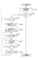
図9は、モータ制御装置157によるモータの制御方法を示すフローチャートである。以下に、図9を用いて、本実施形態におけるモータ509の制御について説明する。このフローチャートの処理は、CPU151aからの指示を受けたモータ制御装置157によって実行される。なお、このフローチャートの処理が実行されている期間中、指令生成器500は、位相決定器513が回転位相θを出力する周期に対応した周期で当該回転位相θを取得している。
FIG. 9 is a flowchart showing a motor control method by the
まず、CPU151aからモータ制御装置157にenable信号‘H’が出力されると、モータ制御装置157はCPU151aから出力される指令に基づいてモータ509の駆動を開始する。enable信号とは、モータ制御装置157の稼働を許可又は禁止する信号である。enable信号が‘L(ローレベル)’である場合は、CPU151aはモータ制御装置157の稼働を禁止する。即ち、モータ制御装置157によるモータ509の制御は終了される。また、enable信号が‘H(ハイレベル)’である場合は、CPU151aはモータ制御装置157の稼働を許可して、モータ制御装置157はCPU151aから出力される指令に基づいてモータ509の制御を行う。
First, when the enable signal ‘H’ is output from the
次に、S1001において、制御切替器515は、モータ509の駆動が定電流制御器517によって制御される状態になるように切替信号‘H’を出力する。その結果、定電流制御器517による定電流制御が行われる。
Next, in S1001, the
その後、S1002において、CPU151aからモータ制御装置157にenable信号‘L’が出力された場合は、モータ制御装置157はモータ509の駆動を終了する。
After that, when the enable signal ‘L’ is output from the
また、S1002おいて、CPU151aからモータ制御装置157にenable信号‘H’が出力されている場合は、モータ制御装置157は処理をS1003に進める。
Further, in S1002, when the enable signal ‘H’ is output from the
次に、S1003において、回転速度ω_ref´が閾値ωth未満である場合は、処理は再びS1001に戻る。即ち、定電流制御器517による定電流制御が維持される。
Next, in S1003, when the rotation speed ω_ref'is less than the threshold value ωth, the process returns to S1001 again. That is, the constant current control by the constant
また、S1003において、回転速度ω_ref´が閾値ωth以上である場合は、S1004において、制御切替器515は、切替信号を‘H’から‘L’に切り替えて出力する。
Further, in S1003, when the rotation speed ω_ref'is equal to or higher than the threshold value ωth, in S1004, the
その後、S1005において、指令値生成器500cは、切替信号が‘H’から‘L’に切り替わる前の最後に入力された回転位相θを指令位相θ_refとして出力する。
After that, in S1005, the
そして、S1006において、所定の遅延時間が経過すると、S1007において、遅延回路519から切替スイッチ516a、516b及び516cに切替信号‘L’が出力される。この結果、ベクトル制御器518によるベクトル制御が行われる。
Then, when the predetermined delay time elapses in S1006, the changeover signal'L'is output from the
S1008において、回転速度ω_ref´が閾値ωth以上である場合は、処理は再びS1007に戻り、ベクトル制御器518によるベクトル制御が続行される。 In S1008, when the rotation speed ω_ref'is equal to or higher than the threshold value ωth, the process returns to S1007 again, and the vector control by the vector controller 518 is continued.
また、S1008において、回転速度ω_ref´が閾値ωthより小さい場合は、S1009において、切替信号が‘L’から‘H’に切り替わる前の最後に出力した指令位相θ_refに、位相差δを加算した位相を指令位相θ_refとして出力する。 Further, in S1008, when the rotation speed ω_ref'is smaller than the threshold value ωth, in S1009, the phase obtained by adding the phase difference δ to the last output command phase θ_ref before the switching signal is switched from'L'to'H'. Is output as the command phase θ_ref.
その後、処理は再びS1001に戻り、制御切替器515は、モータ509の駆動を制御する制御器を切り替える。即ち、制御切替器515は、モータ509を制御する制御器をベクトル制御器518から定電流制御器517に切り替えるように切替信号を‘L’から‘H’に切り替えて出力する。遅延回路519は、制御切替器515から切替信号が出力されてから所定の遅延時間後に、入力された当該切替信号を切替スイッチ516a、516b、516cに出力する。その結果、切替スイッチ516a、516b、516cの状態が切り替わり、定電流制御器517による定電流制御が行われる。
After that, the process returns to S1001 again, and the
以降、CPU151aがモータ制御装置157にenable信号‘L’を出力するまで、モータ制御装置157は上述の制御を繰り返し行う。なお、ベクトル制御中であっても、CPU151aがモータ制御装置157にenable信号‘L’を出力した場合は、モータ制御装置157はモータの制御を中止する。
After that, the
以上のように、本実施形態では、指令生成器500は、モータの制御方法が定電流制御からベクトル制御に切り替わる際に、出力する指令位相θ_refを調整する。具体的には、指令生成器500(指令値生成器500b)は、制御切替器515から入力される切替信号が‘H’から‘L’に切り替わると、当該切替信号が‘H’から‘L’に切り替わる前の最後に入力された回転位相θを指令位相θ_refとして出力する。この結果、モータの制御が定電流制御からベクトル制御に切り替わる際に指令位相と回転子の回転位相との位相差が減少することに起因してモータの回転速度が変動してしまうことを抑制することができる。即ち、モータを制御する制御モードが切り替わる際にモータの制御が不安定になることを抑制することができる。
As described above, in the present embodiment, the
また、指令生成器500は、モータの制御方法がベクトル制御から定電流制御に切り替わる際に、指令位相θ_refを調整する。具体的には、指令値生成器500bは、切替信号が‘L’から‘H’に切り替わる前の最後に出力した指令位相θ_refに、位相差δを加算した位相を指令位相θ_refとして出力する。この結果、モータの制御がベクトル制御から定電流制御に切り替わる際に指令位相と回転子の回転位相との位相差が増大することに起因してモータの回転速度が変動してしまうことを抑制することができる。即ち、モータを制御する制御モードが切り替わる際にモータの制御が不安定になることを抑制することができる。
Further, the
なお、本実施形態では、指令生成器500は、モータの制御方法がベクトル制御から定電流制御に切り替わる際に、指令位相θ_refを以下のようにして調整した。具体的には、指令生成器500は、切替信号が‘L’から‘H’に切り替わる前の最後に出力した指令位相θ_refに、メモリ500cに記憶されている位相差δを加算した位相を指令位相θ_refとして出力したが、この限りではない。例えば、指令生成器500は、切替信号が‘L’から‘H’に切り替わる前の最後に座標変換器511によって変換された電流値iqと位相決定器513によって決定された回転位相θとに基づいて、指令位相θ_refを生成してもよい。具体的には、例えば、指令位相θ_refと回転位相θとの位相差(負荷角)と電流値iqとの関係を示すテーブルがROM151bに格納されており、指令生成器500は、当該テーブルと電流値iqとに基づいて負荷角を決定する。そして、指令生成器500は、当該負荷角を回転位相θに加算することによって指令位相θ_refを生成して出力してもよい。また、指令生成器500は、予め実験等で決定された位相θ0を、切替信号が‘L’から‘H’に切り替わる前の最後に生成した指令位相θ_refに加算することによって指令位相θ_refを生成して出力してもよい。なお、位相θ0は、例えば、定電流制御の実行中に回転子にかかる負荷トルクに基づいて設定されても良いし、ベクトル制御の実行中に回転子にかかる負荷トルクに基づいて設定されても良い。
In this embodiment, the
〔第2実施形態〕
画像形成装置及びモータ制御装置の構成が第1実施形態と同様である部分については、説明を省略する。
[Second Embodiment]
The description of the portion where the configuration of the image forming apparatus and the motor control apparatus is the same as that of the first embodiment will be omitted.
第1実施形態において説明したように、位相差δ(負荷角)はモータの回転子にかかる負荷トルクに対応する値であり、当該負荷トルクが大きいほど大きくなる。例えば、時刻tc2における負荷トルクが時刻tc1における負荷トルクよりも大きい場合、時刻tc2における位相差δは時刻tc1における位相差δよりも大きい。 As described in the first embodiment, the phase difference δ (load angle) is a value corresponding to the load torque applied to the rotor of the motor, and becomes larger as the load torque is larger. For example, when the load torque at time ct2 is larger than the load torque at time ct1, the phase difference δ at time ct2 is larger than the phase difference δ at time ct1.
制御方法が定電流制御からベクトル制御に切り替わる際にメモリ500cに記憶された位相差δが、制御方法がベクトル制御から定電流制御に切り替わる際の指令位相θ_refの調整量として用いられる場合、以下のことが起こる可能性がある。具体的には、例えば、時刻tc2における負荷トルクが時刻tc1における負荷トルクよりも大きいと、制御方法がベクトル制御から定電流制御に切り替わった直後の負荷角に対応するトルクが負荷トルクに比べて小さいことに起因してモータの制御が不安定になってしまう可能性がある。そこで、本実施形態では、以下の構成が適用されることによって、モータを制御する制御モードが切り替わる際にモータの制御が不安定になることを抑制する。
When the phase difference δ stored in the
図10は、本実施形態におけるモータ制御装置157の構成の例を示すブロック図である。本実施形態では、図10に示すように、座標変換器511から出力された電流値iqは指令生成器500に入力される。
FIG. 10 is a block diagram showing an example of the configuration of the
図11は、本実施形態におけるモータの制御切替時の処理方法を説明する図である。図11の実線はモータの指令位相θ_refを示し、破線は回転子の回転位相θを示す。 FIG. 11 is a diagram illustrating a processing method at the time of control switching of the motor in the present embodiment. The solid line in FIG. 11 indicates the command phase θ_ref of the motor, and the broken line indicates the rotation phase θ of the rotor.
本実施形態では、指令値生成器500bは、切替信号が‘H’から‘L’に切り替わると、当該切替信号が‘H’から‘L’に切り替わる前の最後に入力された回転位相θを指令位相θ_refとして出力する。なお、指令値生成器500bは、切替信号が‘H’から‘L’に切り替わる前の最後に入力された回転位相θと切替信号が‘H’から‘L’に切り替わる前の最後に出力した指令位相θ_refとの位相差δをメモリ500cに記憶する。更に、指令値生成器500bは、切替信号が‘H’から‘L’に切り替わると、当該切替信号が‘H’から‘L’に切り替わる前の最後に入力された電流値iqを電流値iq1としてメモリ500cに記憶する。
In the present embodiment, when the switching signal is switched from'H'to'L', the
切替信号が‘L’から‘H’に切り替わると、指令値生成器500bは、メモリ500cに記憶されている位相差δ及び電流値iq1と切替信号が‘L’から‘H’に切り替わる前の最後に入力された電流値iq2とに基づいて、位相θ´を生成する。そして、指令値生成器500bは、切替信号が‘L’から‘H’に切り替わる前の最後に出力した指令位相θ_refに位相θ´を加算した位相を指令位相θ_refとして出力する。なお、指令値生成器500bは、以下の式(12)に基づいて、位相θ´を生成する。
θ´=δ*iq2/iq1 (12)
When the switching signal is switched from'L'to'H', the
θ'= δ * iq2 / iq1 (12)
その後、指令値生成器500bは、位相θ´が加算された指令位相θ_refを初期値として、パルス生成器500bから入力されるパルス信号に基づいて指令位相θ_refを生成して出力する。
After that, the
なお、切替信号が制御切替器515から出力されてから、遅延回路519が当該切替信号を遅延させる所定の遅延時間は、指令値生成器500bが上述の処理を行う時間より長く、切替信号が制御切替器515から出力される周期より短い時間である。
After the switching signal is output from the
以上のように、本実施形態では、指令値生成器500bは、電流値iq1、電流値iq2及び位相差δに基づいて、指令位相θ_refの調整量(位相θ´)を決定する。具体的には、指令値生成器500bは、電流値iq1に対する電流値iq2の比率を位相差δに乗算することによって得られる位相θ´を指令位相θ_refに加算することによって指令位相θ_refを調整する。この結果、時刻tc2における負荷トルクが時刻tc1における負荷トルクよりも大きい場合であっても、制御方法がベクトル制御から定電流制御に切り替わる際にモータの制御が不安定になってしまうことを抑制することができる。即ち、モータを制御する制御モードが切り替わる際にモータの制御が不安定になることを抑制することができる。
As described above, in the present embodiment, the
なお、第1実施形態及び第2実施形態では、制御方法が定電流制御からベクトル制御に切り替わる際に、指令値生成器500bは、切替信号が‘H’から‘L’に切り替わる前の最後に入力された回転位相θを指令位相θ_refとして出力したが、この限りではない。例えば、指令値生成器500bは、切替信号が‘H’から‘L’に切り替わる前の最後に出力した指令位相θ_refよりも遅れた位相且つ切替信号が‘H’から‘L’に切り替わる前の最後に入力された回転位相θよりも進んだ位相を指令位相θ_refとして出力してもよい。このとき出力される指令位相θ_refは、例えば、切替信号が‘H’から‘L’に切り替わる前の最後に入力された回転位相θよりも所定量進んだ位相になるように、入力される回転位相θに基づいて決定される。
In the first embodiment and the second embodiment, when the control method is switched from the constant current control to the vector control, the
また、指令値生成器500bは、切替信号が‘H’から‘L’に切り替わる前の最後に検出された駆動電流のトルク電流成分(電流値iq)に基づいて、出力する指令位相θ_refを生成して出力してもよい。具体的には、例えば、指令値生成器500bは、ROM151に格納された、指令位相θ_refと回転位相θとの位相差(負荷角)と電流値iqとの関係を示すテーブル及び電流値iqに基づいて、出力する指令位相θ_refを生成して出力してもよい。
Further, the
また、指令値生成器500bは、以下の式(13)に基づいて指令位相θ_refを補正し、補正後の位相θ_ref´を指令位相θ_refとして出力してもよい。
θ_ref´=θ_ref−θc (13)
Further, the
θ_ref'= θ_ref-θc (13)
なお、補正値θcは、例えば、モータが駆動する負荷に起因して当該モータの回転子にかかる負荷トルクに基づいて予め設定される値であり、ROM151bに予め格納されている値である。補正値θcは、例えば、補正後の位相θ_ref´が、切替信号が‘H’から‘L’に切り替わる前の最後に出力した指令位相θ_refよりも遅れた位相且つ切替信号が‘H’から‘L’に切り替わる前の最後に入力された回転位相θよりも進んだ位相になるように設定される。
The correction value θc is, for example, a value preset based on the load torque applied to the rotor of the motor due to the load driven by the motor, and is a value stored in advance in the
また、第1実施形態及び第2実施形態においては、連続する駆動パルスの立ち下がりエッジの時間間隔に基づいて速度生成器500aが回転速度ω_ref´を生成したがこの限りではない。例えば、CPU151aが、予め決められたモータの動作シーケンスに基づいて回転速度ω_ref´を生成し、当該回転速度ω_ref´を制御切替器515に所定の周期で出力する構成でもよい。
Further, in the first embodiment and the second embodiment, the
また、第1実施形態及び第2実施形態において、ベクトル制御器518を用いてモータ509の駆動を制御する回路は本発明における第1の制御回路に相当する。更に、第1実施形態及び第2実施形態において、定電流制御器517を用いてモータ509の駆動を制御する回路は本発明における第2の制御回路に相当する。
Further, in the first embodiment and the second embodiment, the circuit for controlling the drive of the
また、第1実施形態及び第2実施形態においては、負荷を駆動するモータとしてステッピングモータが用いられているが、DCモータ等の他のモータであっても良い。また、モータは2相モータである場合に限らず、3相モータ等の他のモータであっても第1実施形態、第2実施形態を適用することができる。 Further, in the first embodiment and the second embodiment, the stepping motor is used as the motor for driving the load, but other motors such as a DC motor may be used. Further, the motor is not limited to the case of a two-phase motor, and the first embodiment and the second embodiment can be applied to other motors such as a three-phase motor.
また、第1実施形態及び第2実施形態においては、回転子として永久磁石が用いられているが、これに限定されるものではない。 Further, in the first embodiment and the second embodiment, a permanent magnet is used as the rotor, but the present invention is not limited to this.
151a CPU
157 モータ制御装置
402 回転子
500 指令生成器
502 位相制御器
507,508 電流検出器
509 ステッピングモータ
513 位相決定器
517 定電流制御器
518 ベクトル制御器
151a CPU
157
Claims (8)
前記モータの回転子の回転によって前記巻線に誘起される誘起電圧の大きさを、前記検出手段によって検出された駆動電流に基づいて決定する誘起電圧決定手段と、
前記誘起電圧決定手段によって決定された誘起電圧の大きさに基づいて、前記回転子の回転位相を決定する位相決定手段と、
前記回転子の目標位相を表す指令位相を生成する生成手段と、
前記生成手段によって生成された前記指令位相と前記位相決定手段によって決定された前記回転位相との偏差が小さくなるように、前記位相決定手段によって決定された回転位相に基づく回転座標系において表される電流成分であって前記回転子にトルクを発生させる電流成分であるトルク電流成分に基づいて、前記巻線に流れる駆動電流を制御する第1制御モードと、前記生成手段によって生成された前記指令位相と予め決められた大きさの電流とに基づいて前記駆動電流を制御する第2制御モードと、を備える制御手段と、
を有し、
前記位相決定手段は、前記第2制御モードの実行中においても、前記回転位相を決定し、
前記生成手段は、前記制御手段により前記モータが加速されている加速期間に前記駆動電流を制御する制御モードが前記第2制御モードから前記第1制御モードに切り替わった場合の当該第1制御モードにおける前記指令位相を、前記加速期間における前記第2制御モードにおいて前記位相決定手段によって決定された前記回転位相に基づいて生成し、
前記生成手段は、前記制御手段により前記モータが減速されている減速期間に前記制御モードが前記第1制御モードから前記第2制御モードに切り替わった場合の当該第2制御モードにおける前記指令位相を、前記加速期間における前記第2制御モードにおいて前記位相決定手段によって決定された前記回転位相と前記加速期間における前記第2制御モードにおいて前記生成手段によって生成された指令位相とに基づいて生成することを特徴とするモータ制御装置。 A detection means that detects the drive current flowing through the windings of the motor,
An induced voltage determining means for determining the magnitude of the induced voltage induced in the winding by the rotation of the rotor of the motor based on the drive current detected by the detecting means.
A phase determining means for determining the rotational phase of the rotor based on the magnitude of the induced voltage determined by the induced voltage determining means,
A generation means for generating a command phase representing the target phase of the rotor, and
It is represented in a rotational coordinate system based on the rotational phase determined by the phase determining means so that the deviation between the command phase generated by the generating means and the rotational phase determined by the phase determining means is small. The first control mode for controlling the drive current flowing through the winding based on the torque current component which is a current component and is the current component for generating torque in the rotor, and the command phase generated by the generation means. When the control means comprising a second control mode, the controlling the drive current based on a current of a predetermined magnitude,
Have,
The phase determining means determines the rotational phase even during execution of the second control mode.
It said generating means in said first control mode when the control mode for controlling the drive current in the acceleration period in which the motor is accelerated is switched from the second control mode to said first control mode by the control means The command phase is generated based on the rotation phase determined by the phase determining means in the second control mode during the acceleration period .
The generation means sets the command phase in the second control mode when the control mode is switched from the first control mode to the second control mode during the deceleration period in which the motor is decelerated by the control means. It is characterized in that it is generated based on the rotation phase determined by the phase determining means in the second control mode in the acceleration period and the command phase generated by the generation means in the second control mode in the acceleration period. Motor control device.
前記生成手段は、前記減速期間に前記制御モードが前記第1制御モードから前記第2制御モードに切り替わった場合の当該第2制御モードにおける前記指令位相を、前記格納手段に格納された前記差分値に基づいて生成することを特徴とする請求項1に記載のモータ制御装置。The generation means stores the command phase in the second control mode when the control mode is switched from the first control mode to the second control mode during the deceleration period, and the difference value stored in the storage means. The motor control device according to claim 1, wherein the motor control device is generated based on the above.
前記生成手段は、パルス生成手段から出力される前記パルス列の各パルスが入力される毎に前記指令位相に所定の変化量を加算することによって前記指令位相を更新することを特徴とする請求項1乃至3のいずれか一項に記載のモータ制御装置。 The motor control device has a pulse generation means for generating a pulse train.
It said generating means, claims and updates the command phase by each pulse of the pulse train output from the pulse generating means for adding a constant amount of change Tokoro the command phase each input The motor control device according to any one of 1 to 3.
前記制御手段は、前記速度決定手段によって決定される前記回転速度が所定値より大きい値になった場合に、前記制御モードを前記第2制御モードから前記第1制御モードに切り替えることを特徴とする請求項4に記載のモータ制御装置。 The control means has a speed determining means for determining a rotation speed corresponding to a target speed of the rotor based on the frequency of the pulse train output from the pulse generating means.
It said control means, wherein when said said rotational speed determined by the speed determining means becomes a predetermined value greater than the value, to switch the pre-SL control mode from the second control mode to said first control mode The motor control device according to claim 4.
前記搬送ローラを駆動するモータと、
請求項1乃至6のいずれか一項に記載のモータ制御装置と、
を有し、
前記モータ制御装置は、前記搬送ローラを駆動するモータの駆動を制御することを特徴とするシート搬送装置。 A transport roller that transports the sheet and
The motor that drives the transfer roller and
The motor control device according to any one of claims 1 to 6.
Have,
The motor control device is a sheet transfer device characterized in that it controls the drive of a motor that drives the transfer roller.
負荷を駆動するモータと、
請求項1乃至6のいずれか一項に記載のモータ制御装置と、
を有し、
前記モータ制御装置は、前記負荷を駆動するモータの駆動を制御することを特徴とする画像形成装置。 An image forming apparatus that forms an image on a recording medium.
The motor that drives the load and
The motor control device according to any one of claims 1 to 6.
Have,
The motor control device is an image forming device characterized in that it controls the drive of a motor that drives the load.
Priority Applications (3)
| Application Number | Priority Date | Filing Date | Title |
|---|---|---|---|
| JP2018026352A JP6980555B2 (en) | 2018-02-16 | 2018-02-16 | Motor control device, sheet transfer device and image forming device |
| US16/262,614 US10637382B2 (en) | 2018-02-16 | 2019-01-30 | Motor control apparatus, sheet conveyance apparatus, and image forming apparatus |
| CN201910114099.0A CN110165958B (en) | 2018-02-16 | 2019-02-14 | Motor control device, sheet conveying device, and image forming apparatus |
Applications Claiming Priority (1)
| Application Number | Priority Date | Filing Date | Title |
|---|---|---|---|
| JP2018026352A JP6980555B2 (en) | 2018-02-16 | 2018-02-16 | Motor control device, sheet transfer device and image forming device |
Publications (3)
| Publication Number | Publication Date |
|---|---|
| JP2019146308A JP2019146308A (en) | 2019-08-29 |
| JP2019146308A5 JP2019146308A5 (en) | 2021-03-04 |
| JP6980555B2 true JP6980555B2 (en) | 2021-12-15 |
Family
ID=67618205
Family Applications (1)
| Application Number | Title | Priority Date | Filing Date |
|---|---|---|---|
| JP2018026352A Active JP6980555B2 (en) | 2018-02-16 | 2018-02-16 | Motor control device, sheet transfer device and image forming device |
Country Status (3)
| Country | Link |
|---|---|
| US (1) | US10637382B2 (en) |
| JP (1) | JP6980555B2 (en) |
| CN (1) | CN110165958B (en) |
Families Citing this family (2)
| Publication number | Priority date | Publication date | Assignee | Title |
|---|---|---|---|---|
| JP6849729B2 (en) * | 2019-04-15 | 2021-03-24 | キヤノン株式会社 | Motor control device, sheet transfer device and image forming device |
| CN113386475B (en) * | 2021-04-30 | 2022-10-11 | 深圳市博思得科技发展有限公司 | Paper feeding precision calibration method and calibration system |
Family Cites Families (11)
| Publication number | Priority date | Publication date | Assignee | Title |
|---|---|---|---|---|
| JP4099845B2 (en) * | 1998-01-29 | 2008-06-11 | 三菱電機株式会社 | Machine operation control device and stop command generation device |
| JP2000166007A (en) * | 1998-12-01 | 2000-06-16 | Hitachi Ltd | Controller for motor car |
| JP2005039955A (en) | 2003-07-17 | 2005-02-10 | Yaskawa Electric Corp | Driving method and control device for stepping motor |
| JP4979646B2 (en) * | 2008-07-17 | 2012-07-18 | オリエンタルモーター株式会社 | Stepping motor drive control device |
| GB2465379A (en) | 2008-11-17 | 2010-05-19 | Technelec Ltd | Controller for electrical machines |
| JP5338776B2 (en) * | 2010-08-31 | 2013-11-13 | ブラザー工業株式会社 | Stepping motor control device and image reading device |
| JP5770701B2 (en) * | 2012-10-05 | 2015-08-26 | シナノケンシ株式会社 | Stepping motor drive control device |
| JP6498227B2 (en) * | 2016-03-30 | 2019-04-10 | キヤノン株式会社 | Sheet conveying apparatus and image forming apparatus |
| US10277152B2 (en) * | 2016-03-30 | 2019-04-30 | Canon Kabushiki Kaisha | Motor control apparatus, sheet conveying apparatus, image forming apparatus |
| JP6745659B2 (en) * | 2016-07-07 | 2020-08-26 | キヤノン株式会社 | Motor control device, sheet conveying device, and image forming device |
| JP2018019510A (en) * | 2016-07-28 | 2018-02-01 | キヤノン株式会社 | Motor control apparatus and image forming apparatus |
-
2018
- 2018-02-16 JP JP2018026352A patent/JP6980555B2/en active Active
-
2019
- 2019-01-30 US US16/262,614 patent/US10637382B2/en active Active
- 2019-02-14 CN CN201910114099.0A patent/CN110165958B/en active Active
Also Published As
| Publication number | Publication date |
|---|---|
| JP2019146308A (en) | 2019-08-29 |
| CN110165958A (en) | 2019-08-23 |
| CN110165958B (en) | 2023-02-17 |
| US10637382B2 (en) | 2020-04-28 |
| US20190260320A1 (en) | 2019-08-22 |
Similar Documents
| Publication | Publication Date | Title |
|---|---|---|
| JP6505155B2 (en) | Motor control device, sheet conveying device, and image forming apparatus | |
| JP6647262B2 (en) | Motor control device, sheet transport device, document reading device, and image forming device | |
| JP6328172B2 (en) | Motor control apparatus, sheet conveying apparatus, and image forming apparatus | |
| JP6552532B2 (en) | Sheet conveying apparatus and image forming apparatus | |
| JP6980555B2 (en) | Motor control device, sheet transfer device and image forming device | |
| JP7080700B2 (en) | Motor control device, sheet transfer device and image forming device | |
| JP6991758B2 (en) | Sheet transfer device and image forming device | |
| US20180358913A1 (en) | Motor control apparatus, sheet conveyance apparatus, document feeding apparatus, document reading apparatus, and image forming apparatus | |
| JP6728433B2 (en) | Motor control device, sheet conveying device, document reading device, and image forming device | |
| JP6900444B2 (en) | Motor control device, sheet transfer device, and image forming device | |
| JP6643388B2 (en) | Motor control device, sheet conveying device, and image forming device | |
| JP6498227B2 (en) | Sheet conveying apparatus and image forming apparatus | |
| JP6720046B2 (en) | Motor control device, sheet conveying device, document reading device, and image forming device | |
| JP6915133B2 (en) | Motor control device, sheet transfer device, document reader and image forming device | |
| JP2019196272A (en) | Sheet conveyance device and image formation device | |
| JP7233987B2 (en) | image forming device | |
| JP7301556B2 (en) | Motor control device and image forming device | |
| JP6789851B2 (en) | Motor control device, sheet transfer device, document reader and image forming device | |
| JP7034727B2 (en) | Motor control device, sheet transfer device and image forming device | |
| JP2019115087A (en) | Motor controller, image formation device, manuscript feeding device, and manuscript reading device | |
| JP6812505B2 (en) | Sheet transfer device, document feeding device, document reading device and image forming device | |
| JP7208351B2 (en) | MOTOR CONTROL DEVICE, SHEET CONVEYING DEVICE, AND IMAGE FORMING APPARATUS | |
| JP7005733B2 (en) | Motor control device, sheet transfer device, and image forming device | |
| JP6801065B2 (en) | Motor control device, sheet transfer device, document reader and image forming device | |
| JP6849729B2 (en) | Motor control device, sheet transfer device and image forming device |
Legal Events
| Date | Code | Title | Description |
|---|---|---|---|
| A521 | Request for written amendment filed |
Free format text: JAPANESE INTERMEDIATE CODE: A523 Effective date: 20210115 |
|
| A621 | Written request for application examination |
Free format text: JAPANESE INTERMEDIATE CODE: A621 Effective date: 20210115 |
|
| A977 | Report on retrieval |
Free format text: JAPANESE INTERMEDIATE CODE: A971007 Effective date: 20210915 |
|
| A131 | Notification of reasons for refusal |
Free format text: JAPANESE INTERMEDIATE CODE: A131 Effective date: 20210921 |
|
| A521 | Request for written amendment filed |
Free format text: JAPANESE INTERMEDIATE CODE: A523 Effective date: 20210930 |
|
| TRDD | Decision of grant or rejection written | ||
| A01 | Written decision to grant a patent or to grant a registration (utility model) |
Free format text: JAPANESE INTERMEDIATE CODE: A01 Effective date: 20211019 |
|
| A61 | First payment of annual fees (during grant procedure) |
Free format text: JAPANESE INTERMEDIATE CODE: A61 Effective date: 20211117 |
|
| R151 | Written notification of patent or utility model registration |
Ref document number: 6980555 Country of ref document: JP Free format text: JAPANESE INTERMEDIATE CODE: R151 |