JP6967123B1 - How to build a box-shaped roof stand - Google Patents
How to build a box-shaped roof stand Download PDFInfo
- Publication number
- JP6967123B1 JP6967123B1 JP2020114123A JP2020114123A JP6967123B1 JP 6967123 B1 JP6967123 B1 JP 6967123B1 JP 2020114123 A JP2020114123 A JP 2020114123A JP 2020114123 A JP2020114123 A JP 2020114123A JP 6967123 B1 JP6967123 B1 JP 6967123B1
- Authority
- JP
- Japan
- Prior art keywords
- box
- shaped roof
- shaped
- pedestal
- roof
- Prior art date
- Legal status (The legal status is an assumption and is not a legal conclusion. Google has not performed a legal analysis and makes no representation as to the accuracy of the status listed.)
- Active
Links
Images


Landscapes
- Excavating Of Shafts Or Tunnels (AREA)
Abstract
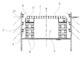
【課題】工法使用予定の箱形ルーフを推進架台として使用することで、推進架台作成に必要な鋼材量の削減、ルーフ置き場の確保、および架台組み直しの作業削減が可能となる箱形ルーフ用架台の構築法を提供する。【解決手段】発進坑に工法使用予定の箱形ルーフ6を先行搬入し、これを積み上げて箱形ルーフ発進用の推進架台5として転用する。【選択図】図1PROBLEM TO BE SOLVED: To reduce the amount of steel required for creating a propulsion pedestal, secure a roof storage space, and reduce the work of reassembling the pedestal by using a box-shaped roof to be used in the construction method as a propulsion pedestal. Provides a construction method for. SOLUTION: A box-shaped roof 6 to be used by the construction method is carried in advance into a starting pit, and the box-shaped roof 6 is stacked and diverted as a propulsion stand 5 for starting the box-shaped roof. [Selection diagram] Fig. 1
Description
本発明は、箱形ルーフを防護工として用いて函体を推進または牽引させて鉄道、道路下に横断地下道を構築する地下構造物の構築方法で使用する箱形ルーフ用架台の構築法に関するものである。 The present invention relates to a method for constructing a frame for a box-shaped roof used in a method for constructing an underground structure for constructing a crossing underpass under a railroad or a road by propelling or towing a box body using a box-shaped roof as a protective work. Is.
鉄道、道路等の下部地中に大幅員の地下構造物を横断方向に掘進させるには、上部交通を支承するための防護工が必要となり、かかる防護工として従来鋼管等を水平に並列させるパイプルーフを設けることなどが挙げられるが、地中に掘進させる地下構造物の防護工を別工事として施工することなく、地下構造物の掘進と同時に行うので安全かつ確実に、しかも安価に工事ができ、また土被りも浅く施工できるものとして、次のようなR&C工法と称する地下構造物の施工法が知られている。 In order to dig a large number of underground structures in the lower ground such as railroads and roads in the crossing direction, a protective work to support the upper traffic is required, and as such a protective work, conventional pipes etc. are arranged horizontally in parallel. For example, installing a roof can be mentioned, but since the protection work for the underground structure to be dug into the ground is not carried out as a separate work, it is carried out at the same time as the excavation of the underground structure, so the work can be done safely, reliably and inexpensively. In addition, the following R & C construction method for underground structures is known as one that can be constructed with a shallow overburden.
これは図25にも示すように、まず、鉄道等上部交通1の脇に土留め鋼矢板2を打設して、発進坑3と到達坑4を築造し、該発進坑3内に推進設備(図示せず)を設置してこれで鋼管による略正方形断面の箱形筒体である箱形ルーフ6を到達坑4に向けて圧入させる。
As shown in FIG. 25, first, a retaining
箱形ルーフ6は側面に継手を長手方向に連続して形成し、また上面に平板からなるフリクションカッタープレート(FCプレート)7を取付けている。
The box-
かかる箱形ルーフ6は単位筒体を1本ずつ圧入するものであり、端部にボルト接合用の継手フランジを形成し、この継手フランジ同士をボルト、ナットで締結することにより1ピースずつ長さ方向に継ぎ足して必要長を埋設し、さらに継手を介して横方向に連続させながら並列させる。
The box-
箱形ルーフ6の並べ方は一文字型、門型、函型などで配設する地下構造物9に合わせて適宜選択される。
The arrangement of the box-
次いで、発進坑3内に反力壁8、コンクリート函体による地下構造物9をセットし、反力壁8と地下構造物9との間には元押しの推進ジャッキ10を設け、地下構造物9の先端に刃口11を設けるとともに地下構造物9の先端と前記箱形ルーフ6との間に小ジャッキ12を介在させる。
Next, a
図中13は箱形ルーフ6の支持材、14はフリクションカッター7の止め部材でこれらは発進坑3側に設け、一方、到達坑4側に受台15を設ける。
In the figure, 13 is a support material for the box-
小ジャッキ12を伸長して地下構造物9を反力としてフリクションカッター7を残しながら箱形ルーフ6を1本ずつ順次押し進め、一通り箱形ルーフ6が前進したならば、小ジャッキ12を縮め、今度は推進ジャッキ10を伸長して地下構造物9を掘進させる。図中16は推進ジャッキ10と地下構造物9間に介在させるストラットである。
The
このようにして、箱形ルーフ6の前進と地下構造物9の前進とを交互に繰り返しながら、到達坑4に出た箱形ルーフ6は順次撤去する。
In this way, the box-
そして、地下構造物9の先端が到達坑4に達したならば、刃口11等を撤去し適宜裏込めグラウトを行って施工を完了する。
Then, when the tip of the
なお、地下構造物9はプレキャスト製のコンクリート函体を発進坑3内に順次吊り下ろして接続していくようにしてもよいし、発進坑3内でコンクリートを打設して必要長を増設するようにしてもよい。
In the
また、地下構造物9の前進方法について、到達坑4側に反力壁及びセンターホール式の牽引ジャッキを設け、一端を地下構造物9に定着したPC鋼線による牽引部材をこの牽引ジャッキで引くことにより到達坑4側から地下構造物9を引き込むようにする工法もある。
Regarding the method of advancing the
下記特許文献は箱形ルーフ6を使用する他の工法例であり、SFT工法“(Simple and Face-Less Method of Construction of Tunnel)「シンプルで切羽の無いトンネルの構築工法」の略称”と名付けられ、下記特許文献1にも掲載されている。
SFT工法は、推進しようとする函体の外形に対応するように箱型ルーフを組み配置して、発進坑から地中に圧入した後、前記箱型ルーフ端部に函体の先端部を配置して函体の推進とともに切羽部の土砂を箱型ルーフといっしょに押し出すことを特徴とする地下構造物の施工法である。 In the SFT method, a box-shaped roof is assembled and arranged so as to correspond to the outer shape of the box to be propelled, and after being pressed into the ground from the starting pit, the tip of the box is arranged at the end of the box-shaped roof. This is a construction method for underground structures, which is characterized by pushing out the earth and sand at the face together with the box-shaped roof while promoting the box body.
箱形ルーフを圧入後、コンクリート函体を推進させる場合、函体の推進とともに切羽部の土砂を箱形ルーフと一緒に押し出すので、切羽部を掘削する作業を別途必要とせず、コスト削減と工期短縮を図ることができ、また、危険を伴う切羽部の掘削作業を省くことで安全性も向上でき、しかも、函体を推進するための反力抵抗を分散することで、大掛かりな設備を必要としない地下構造物の施工法である。 When propelling a concrete box body after press-fitting the box-shaped roof, the earth and sand of the face part is pushed out together with the box-shaped roof, so there is no need to excavate the face part separately, cost reduction and construction period. It can be shortened, safety can be improved by eliminating the dangerous excavation work of the face part, and large-scale equipment is required by distributing the reaction force resistance for propelling the box body. It is a construction method for underground structures.
前記箱形ルーフ6の推進は図27〜図32に示すようにH形鋼等の鋼材で組んだ推進架台5を発進坑内にセットして行われるが、箱形ルーフ6の配置位置(水平又は垂直)により、推進架台5の状態は高低を適宜変化させる。
As shown in FIGS. 27 to 32, the propulsion of the box-
例えば箱形ルーフ6を函型(ロ字形)に配置する場合、上の天井部の横列の箱形ルーフ6を配列し、これを順次、推進ジャッキ18、ストラット19からなる推進設備17で圧入させる。(図27,28)
For example, when the box-
上の横一列の箱形ルーフ6が終えたならば、推進架台5を順次低くして、左右の縦列の箱形ルーフ6を上から下へと並べて挿入して行く。(図29、30)
When the upper horizontal row of box-
この左右の縦列の箱形ルーフ6を挿入し終えたならば、推進架台5は一番低い状態まで解体し、下段の横一列の箱形ルーフ6を挿入して行き、最終的には箱形ルーフ6をロの字(函型)に配列する。(図31、32)
After inserting the left and right vertical rows of box-
このように箱形ルーフ6の施工において、箱形ルーフ6の配置における水平部と垂直部の施工で推進架台5の構造が異なるため、組立直しが発生している。
As described above, in the construction of the box-
前記図25に示す工法(R&C工法)では、水平ルーフを施工した後、架台の両端を解体し、垂直ルーフが施工できるように推進架台5を組み替える。
In the construction method (R & C construction method) shown in FIG. 25, after the horizontal roof is constructed, both ends of the gantry are disassembled and the
前記SFT工法では、下段水平ルーフを施工した後に垂直ルーフ施工の架台を組む。垂直ルーフ用の架台を解体し、上段水平ルーフ用の架台を組み直す。 In the SFT method, a pedestal for vertical roof construction is assembled after the lower horizontal roof is constructed. Dismantle the pedestal for the vertical roof and reassemble the pedestal for the upper horizontal roof.
いずれの場合も作業ヤードの狭い現場では、ルーフの仮置き場が確保できず、必要な本数をその都度、現場に運搬している。 In either case, a temporary storage space for the roof cannot be secured at the site where the work yard is narrow, and the required number of roofs is transported to the site each time.
本発明の目的は前記従来例の不都合を解消し、工法使用予定の箱形ルーフを推進架台として使用することで、推進架台作成に必要な鋼材量の削減、ルーフ置き場の確保、および架台組み直しの作業削減が可能となる箱形ルーフ用架台の構築法を提供することにある。 An object of the present invention is to eliminate the inconvenience of the above-mentioned conventional example and to use a box-shaped roof to be used as a propulsion pedestal to reduce the amount of steel required for creating the propulsion pedestal, secure a roof storage space, and reassemble the gantry. The purpose is to provide a method for constructing a box-shaped roof stand that can reduce work.
前記目的を達成するため請求項1記載の本発明は、発進坑に工法使用予定の箱形ルーフを先行搬入し、これを積み上げて箱形ルーフ発進用の推進架台として転用することを要旨とするものである。
In order to achieve the above object, the gist of the present invention according to
請求項1記載の本発明によれば、工法使用予定の箱形ルーフを発進坑にしてこれで箱形ルーフ発進用の推進架台を組み上げ、その推進架台に使用した箱形ルーフを今度は当該工法に使用する箱形ルーフとして順次接続して推進するものであり、推進架台作成に必要な鋼材量の削減、ルーフ置き場の確保、および架台組み直しの作業削減が可能となる。 According to the first aspect of the present invention, the box-shaped roof to be used in the construction method is used as a starting pit, and a propulsion pedestal for starting the box-shaped roof is assembled. As the box-shaped roof used for the above, it is sequentially connected and propelled, and it is possible to reduce the amount of steel required to create the propulsion pedestal, secure the roof storage space, and reduce the work of reassembling the gantry.
請求項2記載の本発明は、箱形ルーフは井桁に組んで積み上げて箱形ルーフ発進用の推進架台を形成し、これの上から順次、箱形ルーフを挿入に用いて架台高さを低くすることを要旨とするものである。
In the present invention according to
請求項2記載の本発明によれば、門型に施工するものとして、水平部を先に施工し、垂直部を順次下げながら施工する場合に適する。 According to the second aspect of the present invention, it is suitable for the case where the horizontal portion is constructed first and the vertical portion is sequentially lowered as the construction is performed on the gate type.
請求項3記載の本発明は、箱形ルーフは下段水平部を配列し、その左右端の箱形ルーフに上に箱形ルーフを積み上げて順次高さを高くしていくことを要旨とするものである。
The gist of the present invention according to
請求項3記載の本発明によれば、ロ字型(函型)に施工するものとして、垂直部を順次積上げていく場合に適する。 According to the third aspect of the present invention, it is suitable for the case where the vertical portions are sequentially stacked as the construction is performed in a square shape (box shape).
以上述べたように本発明の箱形ルーフ用架台の構築法は、工法使用予定の箱形ルーフを推進架台として使用することで、推進架台作成に必要な鋼材量の削減、ルーフ置き場の確保、および架台組み直しの作業削減が可能となるものである。 As described above, in the method for constructing the box-shaped roof pedestal of the present invention, the amount of steel required for creating the propulsion pedestal is reduced and the roof storage space is secured by using the box-shaped roof to be used as the propulsion pedestal. And it is possible to reduce the work of reassembling the gantry.
以下、図面について本発明の実施の形態を詳細に説明する。図1〜図12は前記図25に示すR&C工法に本発明の箱形ルーフ用架台の構築法を適用する場合であり、図中6は鋼管による略正方形断面の箱形ルーフで、これを門型に配列する場合である。 Hereinafter, embodiments of the present invention will be described in detail with respect to the drawings. 1 to 12 show a case where the method for constructing a box-shaped roof pedestal of the present invention is applied to the R & C method shown in FIG. 25, and FIG. When arranging in a type.
先に箱形ルーフ6について説明すると、図26に示すように端部に継手フランジ6cが形成してあり、継手フランジ6cはボルト挿通孔を形成した板体であり、これを相互に重ねることでボルト・ナット29で締結ができる。
Explaining the box-shaped
箱形ルーフ6は断面形状が1,000×1,000(mm)、長さ3,000(mm)、もしくは、断面形状が800×800(mm)、長さ6,000(mm)で、側面の継手は鉤状の雄型継手6aと雌型継手6bを設けた場合、もしくは鉤状ではない単なる平板の継手の場合、もしくは継手がない場合がある。
The box-shaped
また、箱形ルーフ6は端部隅角を外向き開放の箱抜き6dとし、ここをボルト・ナットの締結部としている。
Further, the box-shaped
箱形ルーフ6の使い方としては、前記図25に示した通りであり、鉄道等上部交通1の脇に土留め鋼矢板2を打設して、発進坑3と到達坑4を築造し、該発進坑3内に圧入機を設置してこれで箱形ルーフ6を到達坑4に向けて圧入させなどである。
The usage of the box-shaped
箱形ルーフ6は、継手フランジ6c同士をボルト・ナット29で締結することにより1ピースずつ長さ方向に継ぎ足して必要長を埋設する。
In the box-shaped
図1、図2に示すように、土留め鋼矢板2を打設して築造した発進坑3内にベース(基礎)20を設置し、その上にR&C工法に使用予定の箱形ルーフ6を先行搬入し、これを井桁に組んで左右に積み上げて箱形ルーフ発進用の推進架台5を構築し、その上に構台21を設けて推進ジャッキ18、ストラット19からなる推進設備17を設置し、箱形ルーフ6を到達坑に向けて推進させる。
As shown in FIGS. 1 and 2, a base (foundation) 20 is installed in the starting
箱形ルーフ6を用いて推進架台5を構築するには、箱形ルーフ6は繋ぎ合わせて必要長のものとしておき、また、略正方形断面の鋼管なので、載置だけで安定して組み立てることができる。
In order to construct the
なお、構台21は左右に分けた箱形ルーフ6の積み上げ推進架台5の上に架け渡すものであり、相互空間にはサポート22を枠組んでこれで構台21の中央部を支承する。
The
水平部である最上段の水平列に箱形ルーフ6を並べて挿入したならば、図3、図4に示すように、構台21も左右に分けて小さなものとし、かつ、高さを下げて、水平列の箱形ルーフ6の左右端の箱形ルーフ6の下側に箱形ルーフ6を重ねて挿入して垂直部の施工を行なう。
If the box-shaped
このようにして、図5、図6に示すように、縦方向の箱形ルーフ6を重ねて挿入して行くが、その際、推進架台5は上部から解体して高さを低め、解体した箱形ルーフ6は挿入に用いる。
In this way, as shown in FIGS. 5 and 6, the vertical box-shaped
図7、図8は垂直部の途中の段階を示し、図9、図10はさらに垂直部を下方に伸ばした途中の段階を示す。 7 and 8 show a stage in the middle of the vertical portion, and FIGS. 9 and 10 show a stage in the middle of extending the vertical portion further downward.
図11、図12はさらに垂直部を下方に伸ばした途中の段階を示す。 11 and 12 show a stage in which the vertical portion is further extended downward.
このようにして図示は省略するが、推進架台5を構成するすべての箱形ルーフ6を挿入に使用し、門型に箱形ルーフ6を配置して地下構造物9の前進に備える。
Although not shown in this way, all the box-shaped
図13〜図24は前記SFT工法に本発明の箱形ルーフ用架台の構築法を適用する場合であり、ロ字型(函型)に箱形ルーフ6を配置して地下構造物9の前進に備える場合である。
13 to 24 are cases where the method for constructing a box-shaped roof stand of the present invention is applied to the SFT method, and the box-shaped
この場合は発進坑3内にベース(基礎)20を設置し、図13、図14に示すように、水平部である最下段の水平列に箱形ルーフ6を並べて挿入し、その左右端の箱形ルーフ6の後方には使用予定の箱形ルーフ6を搬入して、これを推進架台5として使用する。
In this case, a base (foundation) 20 is installed in the starting
推進架台5を用いて、最下段の水平列に箱形ルーフ6の左右端の箱形ルーフ6の上に箱形ルーフ6を積み重ねて挿入する。
Using the
同様に推進架台5の上に箱形ルーフ6を積み重ねて推進架台5の高さを増し、垂直部の箱形ルーフ6を順次挿入施工する。(図15、図16、図17、図18、図19、図20、図21、図22)
Similarly, the box-shaped
左右の垂直部の箱形ルーフ6の挿入施工を完了したならば、図23,24に示すように、別途H形鋼等の鋼材で組んだ架台23を構築し、その上に構台21を設けて推進ジャッキ18、ストラット19からなる推進設備17を設置し、箱形ルーフ6を到達坑に向けて推進させる。この箱形ルーフ6は前記推進架台5に使用した箱形ルーフ6を用いる。(a)の部分の箱形ルーフ6を(b)の部分の箱形ルーフ6に転用するものである。
After the insertion work of the box-shaped
なお、構台21を設けるについは、構台21の中央部はサポート22で支承する。
When the
1…上部交通 2…土留め鋼矢板
3…発進坑 4…到達坑
5…推進架台 6…箱形ルーフ
6a、6b…継手 6c…継手フランジ
6d…箱抜き 7…フリクションカッタープレート
8…反力壁 9…地下構造物
10…推進ジャッキ 11…刃口
12…小ジャッキ 13…支持材
14…止め部材 15…受台
16…ストラット 17…推進設備
18…推進ジャッキ 19…ストラット
20…ベース(基礎) 21…構台
22…サポート 23…架台
29…ボルト・ナット
1 ...
Claims (3)
Priority Applications (1)
| Application Number | Priority Date | Filing Date | Title |
|---|---|---|---|
| JP2020114123A JP6967123B1 (en) | 2020-07-01 | 2020-07-01 | How to build a box-shaped roof stand |
Applications Claiming Priority (1)
| Application Number | Priority Date | Filing Date | Title |
|---|---|---|---|
| JP2020114123A JP6967123B1 (en) | 2020-07-01 | 2020-07-01 | How to build a box-shaped roof stand |
Publications (2)
| Publication Number | Publication Date |
|---|---|
| JP6967123B1 true JP6967123B1 (en) | 2021-11-17 |
| JP2022012335A JP2022012335A (en) | 2022-01-17 |
Family
ID=78509571
Family Applications (1)
| Application Number | Title | Priority Date | Filing Date |
|---|---|---|---|
| JP2020114123A Active JP6967123B1 (en) | 2020-07-01 | 2020-07-01 | How to build a box-shaped roof stand |
Country Status (1)
| Country | Link |
|---|---|
| JP (1) | JP6967123B1 (en) |
Family Cites Families (6)
| Publication number | Priority date | Publication date | Assignee | Title |
|---|---|---|---|---|
| JPH0663420B2 (en) * | 1989-03-25 | 1994-08-22 | 株式会社奥村組 | How to build an underground structure |
| JP3106303B2 (en) * | 1997-06-03 | 2000-11-06 | 誠 植村 | Box-type roof cylinder |
| JP2005179941A (en) * | 2003-12-17 | 2005-07-07 | San Shield Kk | Base for main push device |
| JP3887383B2 (en) * | 2004-06-04 | 2007-02-28 | 誠 植村 | Construction method for underground structures |
| JP6081512B2 (en) * | 2015-03-20 | 2017-02-15 | 植村 誠 | Construction method for underground structures |
| JP7075821B2 (en) * | 2018-05-31 | 2022-05-26 | 株式会社フジタ | Shield machine moving stand |
-
2020
- 2020-07-01 JP JP2020114123A patent/JP6967123B1/en active Active
Also Published As
| Publication number | Publication date |
|---|---|
| JP2022012335A (en) | 2022-01-17 |
Similar Documents
| Publication | Publication Date | Title |
|---|---|---|
| JP4317843B2 (en) | Construction method for underground structures | |
| JP2008223397A (en) | Construction method for underground structure | |
| JP6967123B1 (en) | How to build a box-shaped roof stand | |
| JP7177233B2 (en) | Start Reaction Force Structure and Method for Concrete Box or Open Shield Machine | |
| JP2020063640A (en) | Spacer and propulsion method for box structure | |
| JP5054164B2 (en) | Construction method for underground structures | |
| JP6982603B2 (en) | Box-shaped roof construction method | |
| CN108979641A (en) | The construction method of structure in ground | |
| CN209907410U (en) | Slope reinforcement supporting structure and pile plate retaining wall | |
| JP6441871B2 (en) | Box roof deflection reduction method for box roof method | |
| JP3116098B2 (en) | Construction method for underground structures | |
| JP6445478B2 (en) | Construction method for underground structures | |
| JP3702265B2 (en) | Roof subsidence prevention apparatus and subsidence prevention method in construction method of underground structure | |
| JP7082225B1 (en) | Construction method of underground structure | |
| JPH02252892A (en) | Method for constructing underground structure | |
| JP6081512B2 (en) | Construction method for underground structures | |
| JP2020066923A (en) | Construction method of underground structure | |
| JP7093930B2 (en) | Main push jack equipment in the box propulsion method and the box propulsion method using it | |
| JP7032737B2 (en) | How to install FC plate fixing member and box structure | |
| JP2732007B2 (en) | How to build underground structures | |
| KR101362465B1 (en) | Trenchless construction method of underground structure | |
| JP2017128944A (en) | Construction method of underground structure | |
| JP7032736B2 (en) | How to install FC plate fixing member and box structure | |
| JP3106302B2 (en) | How to build underground structures | |
| JP4926093B2 (en) | How to build a box structure |
Legal Events
| Date | Code | Title | Description |
|---|---|---|---|
| A621 | Written request for application examination |
Free format text: JAPANESE INTERMEDIATE CODE: A621 Effective date: 20201005 |
|
| TRDD | Decision of grant or rejection written | ||
| A01 | Written decision to grant a patent or to grant a registration (utility model) |
Free format text: JAPANESE INTERMEDIATE CODE: A01 Effective date: 20211019 |
|
| A61 | First payment of annual fees (during grant procedure) |
Free format text: JAPANESE INTERMEDIATE CODE: A61 Effective date: 20211022 |
|
| R150 | Certificate of patent or registration of utility model |
Ref document number: 6967123 Country of ref document: JP Free format text: JAPANESE INTERMEDIATE CODE: R150 |