JP6966839B2 - Breathing aid - Google Patents
Breathing aid Download PDFInfo
- Publication number
- JP6966839B2 JP6966839B2 JP2016560790A JP2016560790A JP6966839B2 JP 6966839 B2 JP6966839 B2 JP 6966839B2 JP 2016560790 A JP2016560790 A JP 2016560790A JP 2016560790 A JP2016560790 A JP 2016560790A JP 6966839 B2 JP6966839 B2 JP 6966839B2
- Authority
- JP
- Japan
- Prior art keywords
- user
- opening
- channel
- teeth
- oral cavity
- Prior art date
- Legal status (The legal status is an assumption and is not a legal conclusion. Google has not performed a legal analysis and makes no representation as to the accuracy of the status listed.)
- Active
Links
- 230000029058 respiratory gaseous exchange Effects 0.000 title claims description 23
- 238000000034 method Methods 0.000 claims description 91
- 210000000214 mouth Anatomy 0.000 claims description 74
- 238000004519 manufacturing process Methods 0.000 claims description 51
- 230000000241 respiratory effect Effects 0.000 claims description 42
- 238000000576 coating method Methods 0.000 claims description 23
- 239000011248 coating agent Substances 0.000 claims description 21
- 229910052751 metal Inorganic materials 0.000 claims description 16
- 239000002184 metal Substances 0.000 claims description 16
- 229920000642 polymer Polymers 0.000 claims description 14
- 239000000654 additive Substances 0.000 claims description 11
- 230000000996 additive effect Effects 0.000 claims description 11
- 210000004373 mandible Anatomy 0.000 claims description 11
- 238000005498 polishing Methods 0.000 claims description 11
- 229920002635 polyurethane Polymers 0.000 claims description 11
- 239000004814 polyurethane Substances 0.000 claims description 11
- 210000001584 soft palate Anatomy 0.000 claims description 9
- 238000002591 computed tomography Methods 0.000 claims description 8
- 238000003384 imaging method Methods 0.000 claims description 8
- 210000002050 maxilla Anatomy 0.000 claims description 8
- 239000004593 Epoxy Substances 0.000 claims description 5
- 229910001069 Ti alloy Inorganic materials 0.000 claims description 5
- 229920001296 polysiloxane Polymers 0.000 claims description 5
- 238000005507 spraying Methods 0.000 claims description 5
- -1 Polyvinylsiloxane Polymers 0.000 claims description 4
- 239000000919 ceramic Substances 0.000 claims description 4
- 229920001971 elastomer Polymers 0.000 claims description 4
- 239000000806 elastomer Substances 0.000 claims description 4
- 238000001914 filtration Methods 0.000 claims description 4
- 229920000052 poly(p-xylylene) Polymers 0.000 claims description 4
- 238000007740 vapor deposition Methods 0.000 claims description 4
- 230000001105 regulatory effect Effects 0.000 claims description 3
- 238000007654 immersion Methods 0.000 claims description 2
- 230000003434 inspiratory effect Effects 0.000 claims description 2
- 230000002829 reductive effect Effects 0.000 claims description 2
- 239000000788 chromium alloy Substances 0.000 claims 2
- 230000003796 beauty Effects 0.000 claims 1
- BFMKFCLXZSUVPI-UHFFFAOYSA-N ethyl but-3-enoate Chemical compound CCOC(=O)CC=C BFMKFCLXZSUVPI-UHFFFAOYSA-N 0.000 claims 1
- 239000012530 fluid Substances 0.000 claims 1
- 210000000515 tooth Anatomy 0.000 description 89
- 210000001847 jaw Anatomy 0.000 description 76
- 125000006850 spacer group Chemical group 0.000 description 38
- 230000008569 process Effects 0.000 description 26
- 206010041235 Snoring Diseases 0.000 description 20
- 229920005989 resin Polymers 0.000 description 17
- 239000011347 resin Substances 0.000 description 17
- 238000013461 design Methods 0.000 description 15
- 239000000463 material Substances 0.000 description 13
- 230000000694 effects Effects 0.000 description 12
- 208000001797 obstructive sleep apnea Diseases 0.000 description 11
- 210000003928 nasal cavity Anatomy 0.000 description 10
- 238000010146 3D printing Methods 0.000 description 8
- 238000011282 treatment Methods 0.000 description 8
- 238000010894 electron beam technology Methods 0.000 description 7
- 238000005516 engineering process Methods 0.000 description 6
- 238000002844 melting Methods 0.000 description 6
- 230000008018 melting Effects 0.000 description 6
- 229920003023 plastic Polymers 0.000 description 6
- 239000004033 plastic Substances 0.000 description 6
- 201000002859 sleep apnea Diseases 0.000 description 6
- XTXRWKRVRITETP-UHFFFAOYSA-N Vinyl acetate Chemical compound CC(=O)OC=C XTXRWKRVRITETP-UHFFFAOYSA-N 0.000 description 5
- 210000001331 nose Anatomy 0.000 description 5
- 230000036961 partial effect Effects 0.000 description 5
- 230000009467 reduction Effects 0.000 description 5
- 208000028911 Temporomandibular Joint disease Diseases 0.000 description 4
- 230000008859 change Effects 0.000 description 4
- 150000002739 metals Chemical class 0.000 description 4
- 239000000123 paper Substances 0.000 description 4
- WAIPAZQMEIHHTJ-UHFFFAOYSA-N [Cr].[Co] Chemical class [Cr].[Co] WAIPAZQMEIHHTJ-UHFFFAOYSA-N 0.000 description 3
- 238000007792 addition Methods 0.000 description 3
- 238000002680 cardiopulmonary resuscitation Methods 0.000 description 3
- 239000000356 contaminant Substances 0.000 description 3
- 230000006378 damage Effects 0.000 description 3
- 238000011049 filling Methods 0.000 description 3
- 230000006870 function Effects 0.000 description 3
- 238000007373 indentation Methods 0.000 description 3
- 230000007794 irritation Effects 0.000 description 3
- 230000000670 limiting effect Effects 0.000 description 3
- 239000007788 liquid Substances 0.000 description 3
- 210000004072 lung Anatomy 0.000 description 3
- 239000000843 powder Substances 0.000 description 3
- 238000001356 surgical procedure Methods 0.000 description 3
- 238000002560 therapeutic procedure Methods 0.000 description 3
- 208000000884 Airway Obstruction Diseases 0.000 description 2
- OKTJSMMVPCPJKN-UHFFFAOYSA-N Carbon Chemical compound [C] OKTJSMMVPCPJKN-UHFFFAOYSA-N 0.000 description 2
- 208000006545 Chronic Obstructive Pulmonary Disease Diseases 0.000 description 2
- 206010014561 Emphysema Diseases 0.000 description 2
- XEKOWRVHYACXOJ-UHFFFAOYSA-N Ethyl acetate Natural products CCOC(C)=O XEKOWRVHYACXOJ-UHFFFAOYSA-N 0.000 description 2
- 208000002193 Pain Diseases 0.000 description 2
- 206010063968 Upper airway resistance syndrome Diseases 0.000 description 2
- NIXOWILDQLNWCW-UHFFFAOYSA-N acrylic acid group Chemical group C(C=C)(=O)O NIXOWILDQLNWCW-UHFFFAOYSA-N 0.000 description 2
- 210000003484 anatomy Anatomy 0.000 description 2
- QVGXLLKOCUKJST-UHFFFAOYSA-N atomic oxygen Chemical compound [O] QVGXLLKOCUKJST-UHFFFAOYSA-N 0.000 description 2
- 230000008901 benefit Effects 0.000 description 2
- 238000007408 cone-beam computed tomography Methods 0.000 description 2
- 238000007796 conventional method Methods 0.000 description 2
- 238000003618 dip coating Methods 0.000 description 2
- 238000002567 electromyography Methods 0.000 description 2
- 210000003811 finger Anatomy 0.000 description 2
- 238000000227 grinding Methods 0.000 description 2
- 208000000122 hyperventilation Diseases 0.000 description 2
- 230000000870 hyperventilation Effects 0.000 description 2
- 238000003754 machining Methods 0.000 description 2
- 230000007246 mechanism Effects 0.000 description 2
- 238000012986 modification Methods 0.000 description 2
- 230000004048 modification Effects 0.000 description 2
- 238000000465 moulding Methods 0.000 description 2
- 210000003205 muscle Anatomy 0.000 description 2
- 210000003300 oropharynx Anatomy 0.000 description 2
- 229910052760 oxygen Inorganic materials 0.000 description 2
- 239000001301 oxygen Substances 0.000 description 2
- 239000002861 polymer material Substances 0.000 description 2
- 238000012545 processing Methods 0.000 description 2
- 230000005855 radiation Effects 0.000 description 2
- 230000000284 resting effect Effects 0.000 description 2
- 238000000110 selective laser sintering Methods 0.000 description 2
- 208000019116 sleep disease Diseases 0.000 description 2
- 208000022925 sleep disturbance Diseases 0.000 description 2
- 210000004872 soft tissue Anatomy 0.000 description 2
- 210000001738 temporomandibular joint Anatomy 0.000 description 2
- 229920001169 thermoplastic Polymers 0.000 description 2
- 239000004416 thermosoftening plastic Substances 0.000 description 2
- 210000004357 third molar Anatomy 0.000 description 2
- 210000003813 thumb Anatomy 0.000 description 2
- 238000009966 trimming Methods 0.000 description 2
- 239000011165 3D composite Substances 0.000 description 1
- 241000894006 Bacteria Species 0.000 description 1
- 229920001651 Cyanoacrylate Polymers 0.000 description 1
- 208000007590 Disorders of Excessive Somnolence Diseases 0.000 description 1
- 208000000059 Dyspnea Diseases 0.000 description 1
- 206010013975 Dyspnoeas Diseases 0.000 description 1
- 206010016059 Facial pain Diseases 0.000 description 1
- 206010020751 Hypersensitivity Diseases 0.000 description 1
- JVTAAEKCZFNVCJ-UHFFFAOYSA-M Lactate Chemical compound CC(O)C([O-])=O JVTAAEKCZFNVCJ-UHFFFAOYSA-M 0.000 description 1
- 208000019693 Lung disease Diseases 0.000 description 1
- MWCLLHOVUTZFKS-UHFFFAOYSA-N Methyl cyanoacrylate Chemical compound COC(=O)C(=C)C#N MWCLLHOVUTZFKS-UHFFFAOYSA-N 0.000 description 1
- 208000001705 Mouth breathing Diseases 0.000 description 1
- 206010028735 Nasal congestion Diseases 0.000 description 1
- 206010028748 Nasal obstruction Diseases 0.000 description 1
- 206010038687 Respiratory distress Diseases 0.000 description 1
- 206010041349 Somnolence Diseases 0.000 description 1
- RTAQQCXQSZGOHL-UHFFFAOYSA-N Titanium Chemical compound [Ti] RTAQQCXQSZGOHL-UHFFFAOYSA-N 0.000 description 1
- 208000027418 Wounds and injury Diseases 0.000 description 1
- 238000009825 accumulation Methods 0.000 description 1
- 239000003570 air Substances 0.000 description 1
- 208000026935 allergic disease Diseases 0.000 description 1
- 230000007815 allergy Effects 0.000 description 1
- 229940035674 anesthetics Drugs 0.000 description 1
- 238000000149 argon plasma sintering Methods 0.000 description 1
- 208000006673 asthma Diseases 0.000 description 1
- 238000006243 chemical reaction Methods 0.000 description 1
- 239000003795 chemical substances by application Substances 0.000 description 1
- 238000004140 cleaning Methods 0.000 description 1
- 239000002131 composite material Substances 0.000 description 1
- 238000012790 confirmation Methods 0.000 description 1
- 208000027744 congestion Diseases 0.000 description 1
- 230000001276 controlling effect Effects 0.000 description 1
- 238000005520 cutting process Methods 0.000 description 1
- 239000005548 dental material Substances 0.000 description 1
- 210000004268 dentin Anatomy 0.000 description 1
- 230000037213 diet Effects 0.000 description 1
- 235000005911 diet Nutrition 0.000 description 1
- 238000007598 dipping method Methods 0.000 description 1
- 239000006185 dispersion Substances 0.000 description 1
- 206010013781 dry mouth Diseases 0.000 description 1
- 238000001035 drying Methods 0.000 description 1
- 239000004744 fabric Substances 0.000 description 1
- 210000000887 face Anatomy 0.000 description 1
- 230000001815 facial effect Effects 0.000 description 1
- 239000010419 fine particle Substances 0.000 description 1
- 238000010100 freeform fabrication Methods 0.000 description 1
- 239000007789 gas Substances 0.000 description 1
- 239000003193 general anesthetic agent Substances 0.000 description 1
- 239000011521 glass Substances 0.000 description 1
- 210000004247 hand Anatomy 0.000 description 1
- 230000036541 health Effects 0.000 description 1
- 239000007943 implant Substances 0.000 description 1
- 210000004283 incisor Anatomy 0.000 description 1
- 208000014674 injury Diseases 0.000 description 1
- 238000003780 insertion Methods 0.000 description 1
- 230000037431 insertion Effects 0.000 description 1
- 230000008407 joint function Effects 0.000 description 1
- 210000003563 lymphoid tissue Anatomy 0.000 description 1
- 230000013011 mating Effects 0.000 description 1
- 239000000203 mixture Substances 0.000 description 1
- 210000001989 nasopharynx Anatomy 0.000 description 1
- 230000002232 neuromuscular Effects 0.000 description 1
- 230000003287 optical effect Effects 0.000 description 1
- 230000037361 pathway Effects 0.000 description 1
- 230000003239 periodontal effect Effects 0.000 description 1
- 230000002688 persistence Effects 0.000 description 1
- 210000003800 pharynx Anatomy 0.000 description 1
- 239000011505 plaster Substances 0.000 description 1
- 230000008092 positive effect Effects 0.000 description 1
- 238000007639 printing Methods 0.000 description 1
- KCTAWXVAICEBSD-UHFFFAOYSA-N prop-2-enoyloxy prop-2-eneperoxoate Chemical group C=CC(=O)OOOC(=O)C=C KCTAWXVAICEBSD-UHFFFAOYSA-N 0.000 description 1
- 230000003252 repetitive effect Effects 0.000 description 1
- 230000005801 respiratory difficulty Effects 0.000 description 1
- 210000002345 respiratory system Anatomy 0.000 description 1
- 208000023504 respiratory system disease Diseases 0.000 description 1
- 238000012552 review Methods 0.000 description 1
- 229920002631 room-temperature vulcanizate silicone Polymers 0.000 description 1
- 210000003296 saliva Anatomy 0.000 description 1
- 238000012216 screening Methods 0.000 description 1
- 238000007493 shaping process Methods 0.000 description 1
- 229920002050 silicone resin Polymers 0.000 description 1
- 230000003860 sleep quality Effects 0.000 description 1
- 239000007787 solid Substances 0.000 description 1
- 238000010561 standard procedure Methods 0.000 description 1
- 239000000126 substance Substances 0.000 description 1
- 230000003746 surface roughness Effects 0.000 description 1
- 230000008961 swelling Effects 0.000 description 1
- 208000024891 symptom Diseases 0.000 description 1
- 238000012360 testing method Methods 0.000 description 1
- 229920001187 thermosetting polymer Polymers 0.000 description 1
- 210000001519 tissue Anatomy 0.000 description 1
- 239000010936 titanium Substances 0.000 description 1
- 229910052719 titanium Inorganic materials 0.000 description 1
- 238000003325 tomography Methods 0.000 description 1
- 238000012549 training Methods 0.000 description 1
- 230000007704 transition Effects 0.000 description 1
- 238000013519 translation Methods 0.000 description 1
- XLYOFNOQVPJJNP-UHFFFAOYSA-N water Chemical compound O XLYOFNOQVPJJNP-UHFFFAOYSA-N 0.000 description 1
- 230000004580 weight loss Effects 0.000 description 1
- 230000002087 whitening effect Effects 0.000 description 1
Images


Classifications
-
- A—HUMAN NECESSITIES
- A61—MEDICAL OR VETERINARY SCIENCE; HYGIENE
- A61F—FILTERS IMPLANTABLE INTO BLOOD VESSELS; PROSTHESES; DEVICES PROVIDING PATENCY TO, OR PREVENTING COLLAPSING OF, TUBULAR STRUCTURES OF THE BODY, e.g. STENTS; ORTHOPAEDIC, NURSING OR CONTRACEPTIVE DEVICES; FOMENTATION; TREATMENT OR PROTECTION OF EYES OR EARS; BANDAGES, DRESSINGS OR ABSORBENT PADS; FIRST-AID KITS
- A61F5/00—Orthopaedic methods or devices for non-surgical treatment of bones or joints; Nursing devices; Anti-rape devices
- A61F5/56—Devices for preventing snoring
- A61F5/566—Intra-oral devices
-
- A—HUMAN NECESSITIES
- A61—MEDICAL OR VETERINARY SCIENCE; HYGIENE
- A61M—DEVICES FOR INTRODUCING MEDIA INTO, OR ONTO, THE BODY; DEVICES FOR TRANSDUCING BODY MEDIA OR FOR TAKING MEDIA FROM THE BODY; DEVICES FOR PRODUCING OR ENDING SLEEP OR STUPOR
- A61M16/00—Devices for influencing the respiratory system of patients by gas treatment, e.g. mouth-to-mouth respiration; Tracheal tubes
- A61M16/10—Preparation of respiratory gases or vapours
- A61M16/1045—Devices for humidifying or heating the inspired gas by using recovered moisture or heat from the expired gas
-
- A—HUMAN NECESSITIES
- A61—MEDICAL OR VETERINARY SCIENCE; HYGIENE
- A61M—DEVICES FOR INTRODUCING MEDIA INTO, OR ONTO, THE BODY; DEVICES FOR TRANSDUCING BODY MEDIA OR FOR TAKING MEDIA FROM THE BODY; DEVICES FOR PRODUCING OR ENDING SLEEP OR STUPOR
- A61M16/00—Devices for influencing the respiratory system of patients by gas treatment, e.g. mouth-to-mouth respiration; Tracheal tubes
- A61M16/10—Preparation of respiratory gases or vapours
- A61M16/105—Filters
- A61M16/106—Filters in a path
- A61M16/107—Filters in a path in the inspiratory path
-
- A—HUMAN NECESSITIES
- A61—MEDICAL OR VETERINARY SCIENCE; HYGIENE
- A61M—DEVICES FOR INTRODUCING MEDIA INTO, OR ONTO, THE BODY; DEVICES FOR TRANSDUCING BODY MEDIA OR FOR TAKING MEDIA FROM THE BODY; DEVICES FOR PRODUCING OR ENDING SLEEP OR STUPOR
- A61M16/00—Devices for influencing the respiratory system of patients by gas treatment, e.g. mouth-to-mouth respiration; Tracheal tubes
- A61M16/20—Valves specially adapted to medical respiratory devices
-
- A—HUMAN NECESSITIES
- A63—SPORTS; GAMES; AMUSEMENTS
- A63B—APPARATUS FOR PHYSICAL TRAINING, GYMNASTICS, SWIMMING, CLIMBING, OR FENCING; BALL GAMES; TRAINING EQUIPMENT
- A63B71/00—Games or sports accessories not covered in groups A63B1/00 - A63B69/00
- A63B71/08—Body-protectors for players or sportsmen, i.e. body-protecting accessories affording protection of body parts against blows or collisions
- A63B71/085—Mouth or teeth protectors
-
- A—HUMAN NECESSITIES
- A61—MEDICAL OR VETERINARY SCIENCE; HYGIENE
- A61M—DEVICES FOR INTRODUCING MEDIA INTO, OR ONTO, THE BODY; DEVICES FOR TRANSDUCING BODY MEDIA OR FOR TAKING MEDIA FROM THE BODY; DEVICES FOR PRODUCING OR ENDING SLEEP OR STUPOR
- A61M2207/00—Methods of manufacture, assembly or production
-
- A—HUMAN NECESSITIES
- A63—SPORTS; GAMES; AMUSEMENTS
- A63B—APPARATUS FOR PHYSICAL TRAINING, GYMNASTICS, SWIMMING, CLIMBING, OR FENCING; BALL GAMES; TRAINING EQUIPMENT
- A63B71/00—Games or sports accessories not covered in groups A63B1/00 - A63B69/00
- A63B71/08—Body-protectors for players or sportsmen, i.e. body-protecting accessories affording protection of body parts against blows or collisions
- A63B71/085—Mouth or teeth protectors
- A63B2071/086—Mouth inserted protectors with breathing holes
Description
本発明は、呼吸を補助するための装置に関し、より詳細には、呼吸補助装置、および呼吸補助装置を製造し嵌め合わせるための方法に関する。 The present invention relates to a device for assisting breathing, and more particularly to a respiratory assist device and a method for manufacturing and fitting the respiratory assist device.
本明細書において、従来の刊行物(またはそこから引き出される情報)または公知事項の参照は、従来の刊行物(またはそこから引き出される情報)または公知事項が、本明細書が関連する努力傾注分野における共通の一般知識の一部を形成する事項であると認識、自認、または任意の形の提案として解釈されるものではなく、解釈すべきではない。 In the present specification, references to conventional publications (or information derived from them) or publicly known matters are the areas of effort in which conventional publications (or information derived from them) or publicly known matters are relevant herein. It is not and should not be construed as a matter that forms part of the common general knowledge in.
質の悪い呼吸または効果的でない呼吸は、人が起きている間および/または寝ているときの日常活動において人のパフォーマンスに影響を与え得る問題である。起きている間、これは、スポーツなどの活動においてまたは日常的な仕事を実行する間でも最適とは言えないパフォーマンスになり得る。寝ている間、呼吸障害は、いびきおよび/または睡眠時無呼吸を招き得る。 Poor or ineffective breathing is a problem that can affect a person's performance during daily activities while a person is awake and / or sleeping. While awake, this can be suboptimal performance in activities such as sports or even while performing routine tasks. While sleeping, respiratory distress can lead to snoring and / or sleep apnea.
いびきは、人間の呼吸経路内の軟質組織の振動によって生じ、通常、睡眠中の呼吸時に、閉塞された気動によって引き起こされる。いびきは、鼻づまりなど様々な身体的要因から生じ、通常、上咽喉の筋肉が睡眠中に弛緩したときに生じる。 Snoring is caused by vibrations of soft tissues in the human respiratory pathway, usually caused by obstructed air movements during sleep breathing. Snoring results from a variety of physical factors, such as stuffy nose, and usually occurs when the muscles of the nasopharynx relax during sleep.
また、いびきは閉塞性睡眠時無呼吸(Obstructive Sleep Apnoea:OSA)を伴う可能性があり、これは上気道の閉塞によって生じ、その結果、正常睡眠中に呼吸が反復的に停止する。OSAを患う人は、しばしば、かなりの睡眠妨害に伴う日中の眠気や疲労感に苦しみ、一方でパートナーの睡眠パターンもまた、それに伴ういびきによって妨害される。 Snoring can also be accompanied by obstructive sleep apnea (OSA), which is caused by obstruction of the upper respiratory tract, resulting in repetitive arrest of breathing during normal sleep. People with OSA often suffer from daytime sleepiness and fatigue associated with significant sleep disturbances, while their partner's sleep patterns are also disturbed by the accompanying snoring.
現在のOSAの治療法には、生活様式の変更、気道を拡大させる口腔内または鼻内装置などの機械的装置の使用、睡眠中の気道を拡大し、安定させるための外科的処置、および持続的または可変式の気道陽圧(positive airway pressure:CPAP、VPAP)装置などがある。 Current treatments for OSA include lifestyle changes, the use of mechanical devices such as intraoral or nasal devices that dilate the airways, surgical procedures to dilate and stabilize the airways during sleep, and persistence. There are positive airway pressure (CPAP, VPAP) devices and the like.
しかし、外科的処置は、難しい場合があるため、絶対的に必要でない限り広くは使用されていない。CPAPおよびVPAP装置は、好影響を与えているが、長期にわたって装着するのが不快になり、また高価で、しばしばうるさく、ひいては、さらなる睡眠妨害を招き得る。したがって、外科的、VPAPおよびCPAPの治療は、睡眠時無呼吸を治療する上で用途が限定されており、一般的には、いびきの適切な治療であるとは考えられていない。 However, surgical procedures can be difficult and are not widely used unless absolutely necessary. CPAP and VPAP devices have a positive effect, but are uncomfortable to wear for long periods of time and can be expensive, often noisy, and thus lead to further sleep disturbances. Therefore, surgical, VPAP and CPAP treatments have limited uses in treating sleep apnea and are generally not considered to be appropriate treatments for snoring.
その他の機械的装置に関して、けん引または副子固定を使用して鼻気道を拡張する鼻内装置が使用されている。しかし、これらは通常、それほど成功しておらず、使用者にとって不快なものになり得る。 For other mechanical devices, intranasal devices that dilate the nasal airways using traction or splint fixation are used. However, these are usually less successful and can be offensive to the user.
特許文献1は、いびき防止装置を記載しており、このいびき防止装置は、使用者の口に挿入するための、近位および遠位端部と、外側周囲とを有する可撓式中空チューブを含む。当該チューブは、その近位端部に口外セグメントと、その遠位端部に口内セグメントと、それらの間を延びる中間セグメントとを含む。口外および口内セグメント各々は、少なくとも1つの開口部を含む。口外セグメントは、使用者の外側唇を超えて延ばすためのものであり、中間セグメントは、使用者の口の頬咽頭通路に沿って延びるのに十分な長さのものであり、口内セグメントは、使用者の口内の大臼歯後方空間を超えて延び、中咽頭内に入り、舌根と軟口蓋の間で終端するのに十分な長さのものである。いびき防止装置はまた、口内セグメントを使用者の中咽頭内に固定するための、口内セグメント上のチューブの外側周囲から延びるストッパを含む。しかし、この配置は、付加的な気道をもたらすのを補助し、したがっていびきおよび無呼吸事象を低減することができるが、着用が不快であり、使用中口内で移動することがあり、それによって装置の効果性を低減し、ひいてはさらなる呼吸問題を招き得る。
特許文献2は、睡眠中に呼吸し易くするための、口内に取り外し可能に挿入可能な装置を記載しており、この装置は、下顎の前方位置決めおよび/または口の奥への加圧された空気の送出によって妨害の無い、閉塞されない気道をもたらす。当該装置は、上側および下側の歯接触部材と、それらの間に画定された気道とを有し、詳細にはCPAP機と共に使用するように設計される。その結果、この装置は、CPAP機が利用可能である限定された状況でのみ使用することができ、睡眠時無呼吸の治療のみに使用される。 U.S. Pat. The delivery of air provides an unobstructed, unobstructed airway. The device has upper and lower tooth contact members and an airway defined between them, and is specifically designed for use with a CPAP machine. As a result, this device can only be used in the limited circumstances in which a CPAP machine is available and is used only for the treatment of sleep apnea.
特許文献3は、呼吸を補助するための装置であって、本体を含み、当該本体が、使用者の歯を受け入れ、それによって本体を使用者の口腔内に位置決めするためのくぼみと、使用者の唇を超えて延びる第1の開口部であって、口腔の外側からの空気が開口部を通って中に引き入れられることを可能にする、第1の開口部と、口腔内に設けられて、空気を口腔の後方領域内に向けることを可能にする第2の開口部と、第1および第2の開口部を連結するチャネルであって、使用者の頬側溝の少なくとも一部を通って延びるチャネルとを含む、装置を記載している。 Patent Document 3 is a device for assisting breathing, which includes a main body, a recess for receiving the user's teeth, thereby positioning the main body in the user's oral cavity, and a user. A first opening that extends beyond the lips and is provided in the oral cavity to allow air from the outside of the oral cavity to be drawn in through the opening. A channel connecting the first and second openings, which allows air to be directed into the posterior region of the oral cavity, through at least a portion of the user's buccal groove. Describes the device, including extending channels.
また、スポーツ時に使用するためのマウスガードを提供することも公知である。たとえば、特許文献4は、歯科装具を記載しており、この歯科装具は、咬合パッドの周りに配設されて歯科装具を使用者の歯に取り外し式に固定するアームを含む。咬合パッドは、さまざまな側面において、柔軟な状態と非柔軟な状態の間で変質可能な咬合パッド材料から形成される。関連する使用方法はまた、本明細書においても開示される。 It is also known to provide a mouthguard for use during sports. For example, Patent Document 4 describes a dental orthotic device, which includes an arm disposed around an occlusal pad to detachably secure the orthotic device to a user's teeth. The occlusal pad is formed from the occlusal pad material that can be altered between the flexible and inflexible states in various aspects. Related usages are also disclosed herein.
特許文献5は、交換可能なマウスガード構成要素システムを記載している。当該システムは、受け入れくぼみがその少なくとも正面表面に位置決めされたマウスガード・ベースと、くぼみ内に嵌まるように位置決めされた固定式に取り付け可能なマウスガード構成要素と、くぼみまたは構成要素の1つ上に位置決めされた1つまたは複数の取り付け支柱と、くぼみまたは構成要素のいずれか上の支柱に対向して位置決めされた1つまたは複数の穴とを含む。マウスガード構成要素は、取り付けられたとき、ベースの実質的に同一平面の正面表面を維持できるように位置決めされる。 Patent Document 5 describes an interchangeable mouthguard component system. The system includes a mouthguard base with the receiving recess positioned at least on its front surface, a fixedly attachable mouthguard component positioned to fit within the recess, and one of the recesses or components. Includes one or more mounting stanchions positioned above and one or more holes positioned facing the stanchions on either the indentation or the component. The mouthguard component is positioned to maintain a substantially coplanar front surface of the base when attached.
しかし、スポーツ時に使用するためのマウスガードは、呼吸補助には適応しておらず、一部の状況では、呼吸しづらくなる場合がある。 However, mouthguards for use during sports are not adapted for breathing assistance and may be difficult to breathe in some situations.
特許文献6は、患者に合わせた歯列矯正装具の製造時に使用する仮想上の歯列矯正部材を作成するための方法を記載している。当該方法は、患者の患者データセットを得るステップであって、患者データセットは、患者の口の上顎および下顎それぞれに類似する仮想の上顎および仮想の下顎を含む、仮想の3D歯モデルを含む、ステップと、患者の終末蝶番運動軸(terminal hinge axis)を表す少なくとも1つの軸に対する動作に少なくとも基づいて、仮想の上顎と仮想の下顎の間の咬み合わせをシミュレートすることができる仮想の咬合器内に、仮想の上顎および仮想の下顎を初期相対構成で配置するステップと、仮想の3D歯モデルおよび仮想の咬合器内の3D歯モデルの配置の少なくとも一部に基づいて仮想の歯列矯正要素を設計するステップとを含む。 Patent Document 6 describes a method for creating a virtual orthodontic member to be used in manufacturing an orthodontic appliance tailored to a patient. The method is a step of obtaining a patient data set of a patient, wherein the patient data set includes a virtual 3D tooth model, including a virtual maxilla and a virtual lower jaw similar to the upper and lower jaws of the patient's mouth, respectively. A virtual articulator that can simulate the occlusion between the virtual maxilla and the virtual lower jaw based on at least the steps and movements with respect to at least one axis representing the patient's terminal tooth axes. A virtual orthodontic element based on the steps of placing the virtual maxilla and virtual lower jaw in an initial relative configuration within, and at least part of the placement of the virtual 3D tooth model and the 3D tooth model within the virtual articulator. Includes steps to design.
しかし、仮想の咬み合わせを用いることは、結果の歯列矯正要素が、患者の顎の特定の咬み合わせを考慮に入れないことがあるため、必ずしも患者にとって快適に最適化されるものではない。 However, the use of virtual occlusal is not always optimized comfortably for the patient, as the resulting orthodontic element may not take into account the particular occlusal of the patient's jaw.
広範な一形態において、本発明は、呼吸を補助するための装置であって、使用者の口腔内に配置するための本体を含み、本体は、
a)使用者の唇間に空気を流すための少なくとも1つの第1の開口部と、
b)口腔内に設けられて、空気流が口腔の後方領域に出入りすることを可能にする2つの第2の開口部と、
c)2つのチャネルであって、各チャネルは、それぞれの前記第2の開口部と前記少なくとも1つの第1の開口部をつなげ、また、各チャネルが、少なくとも部分的に前記頬側口腔に沿って及び/又は少なくとも部分的に前記歯の間を通ることにより、鼻腔を少なくとも部分的に迂回し、健康な鼻腔および咽頭空間を複製するように作用する気道を使用者に提供する、2つのチャネルと
を備える、装置を提供しようとするものである。
In one broad form, the invention includes a body for assisting breathing, the body of which is to be placed in the oral cavity of the user.
a) At least one first opening for allowing air to flow between the user's lips, and
b) Two second openings provided in the oral cavity that allow airflow to enter and exit the posterior region of the oral cavity.
c) Two channels, each connecting the respective second opening to the at least one first opening, and each channel is at least partially along the buccal oral cavity. Two channels that provide the user with an airway that at least partially bypasses the nasal cavity and acts to replicate a healthy nasal cavity and pharyngeal space by passing between the teeth and / or at least partially. It is intended to provide a device equipped with and.
広範な一形態において、本発明は、呼吸を補助するための装置であって、使用者の口腔内に配置するための本体を含み、本体は、
a)使用者の唇間に空気を流すための少なくとも1つの第1の開口部と、
b)口腔内に設けられて、空気流が口腔の後方領域に出入りすることを可能にする2つの第2の開口部と、
c)2つのチャネルであって、各チャネルは、それぞれの前記第2の開口部と前記少なくとも1つの第1の開口部をつなげ、また、各チャネルが、少なくとも部分的に前記頬側口腔に沿って及び/又は少なくとも部分的に前記歯の間を通ることにより、鼻腔を少なくとも部分的に迂回し、健康な鼻腔および咽頭空間を複製するように作用する気道を使用者に提供する、2つのチャネルと
を備える、装置である。
典型的には、装置が安静時の使用に適応するように、各チャネルは、
a)少なくとも10mm2、
b)少なくとも20mm2、
c)少なくとも30mm2、
d)少なくとも40mm2、
e)少なくとも50mm2
の少なくとも1つの断面積を有する。
In one broad form, the invention includes a body for assisting breathing, the body of which is to be placed in the oral cavity of the user.
a) At least one first opening for allowing air to flow between the user's lips, and
b) Two second openings provided in the oral cavity that allow airflow to enter and exit the posterior region of the oral cavity.
c) Two channels, each connecting the respective second opening to the at least one first opening, and each channel is at least partially along the buccal oral cavity. Two channels that provide the user with an airway that at least partially bypasses the nasal cavity and acts to replicate a healthy nasal cavity and pharyngeal space by passing between the teeth and / or at least partially. It is a device provided with.
Typically, each channel will be adapted for use at rest.
a) At least 10 mm 2 ,
b) At least 20 mm 2 ,
c) At least 30 mm 2 ,
d) At least 40 mm 2 ,
e) at least 50 mm 2
Has at least one cross-sectional area of.
典型的には、装置が安静時の使用に適応するように、第1の開口部および第2の開口部の少なくとも1つは、
a)少なくとも50mm2、
b)少なくとも70mm2、
c)少なくとも90mm2、
d)少なくとも100mm2、および
e)少なくとも110mm2
の少なくとも1つの断面積を有する。
Typically, at least one of the first and second openings is such that the device is adapted for resting use.
a) At least 50 mm 2 ,
b) At least 70 mm 2 ,
c) At least 90 mm 2 ,
d) at least 100 mm 2 and e) at least 110 mm 2
Has at least one cross-sectional area of.
典型的には、装置が運動中の使用に適応するように、各チャネルは、
a)少なくとも20mm2、
b)少なくとも40mm2、
c)少なくとも60mm2、
d)少なくとも80mm2、
e)少なくとも100mm2、
f)少なくとも150mm2、
g)少なくとも200mm2、
h)少なくとも250mm2、および
i)少なくとも300mm2
の少なくとも1つの断面積を有する。
Typically, each channel is adapted for use during exercise.
a) At least 20 mm 2 ,
b) At least 40 mm 2 ,
c) At least 60 mm 2 ,
d) At least 80 mm 2 ,
e) At least 100 mm 2 ,
f) at least 150 mm 2 ,
g) At least 200 mm 2 ,
h) at least 250 mm 2 and i) at least 300 mm 2
Has at least one cross-sectional area of.
典型的には、装置が運動中の使用に適応するように、第1の開口部および第2の開口部の少なくとも1つは、
a)少なくとも100mm2、
b)少なくとも140mm2、
c)少なくとも180mm2、
d)少なくとも200mm2、
e)少なくとも220mm2、
f)少なくとも330mm2、
g)少なくとも440mm2、および
h)少なくとも550mm2
の少なくとも1つの断面積を有する。
Typically, at least one of the first and second openings is such that the device adapts for use during exercise.
a) At least 100 mm 2 ,
b) At least 140 mm 2 ,
c) at least 180 mm 2 ,
d) At least 200 mm 2 ,
e) At least 220 mm 2 ,
f) at least 330 mm 2 ,
g) at least 440 mm 2 and h) at least 550 mm 2
Has at least one cross-sectional area of.
典型的には、各チャネルは、
a)使用者の口腔を通り抜けて延びる第1のチャネル部分と、
b)第1のチャネル部分と流体連通し、使用者の上顎歯と下顎歯の間を延びる第2のチャネル部分とを含む。
Typically, each channel
a) The first channel portion extending through the user's oral cavity,
b) Includes a second channel portion that communicates fluidly with the first channel portion and extends between the user's maxillary and mandibular teeth.
典型的には、第1のチャネル部分は、実質的に半楕円形の断面を有し、第2のチャネル部分は、実質的に矩形の断面を有し、第2のチャネル部分は、第1のチャネル部分から横方向に内方向に延びる。 Typically, the first channel portion has a substantially semi-elliptical cross section, the second channel portion has a substantially rectangular cross section, and the second channel portion has a first. Extends laterally and inwardly from the channel portion of.
典型的には、第1および第2のチャネル部分の少なくとも1つの断面形状および断面積の少なくとも1つは、第1の開口部から第2の開口部にかけて変化する。 Typically, at least one of at least one cross-sectional shape and cross-sectional area of the first and second channel portions varies from the first opening to the second opening.
典型的には、チャネルの形状およびサイズは、使用者の口腔の生体構造にしたがって変化する。 Typically, the shape and size of the channel will vary according to the anatomy of the user's oral cavity.
典型的には、本体は、チャネル壁を備え、チャネル壁の少なくとも一部は、
a)0.5mm未満、および
b)約0.3mm
の少なくとも1つの厚さを有する。
Typically, the body comprises a channel wall, at least a portion of the channel wall.
a) less than 0.5 mm, and b) about 0.3 mm
Has at least one thickness of.
典型的には、第1の開口部は、本体に取り外し可能に装着される。 Typically, the first opening is detachably attached to the body.
典型的には、第2の開口部は、
a)10°から50°の間、
b)20°から40°の間、および
c)約30°
の少なくとも1つによって内方向に傾斜される。
Typically, the second opening is
a) Between 10 ° and 50 °
b) between 20 ° and 40 °, and c) about 30 °
Tilt inward by at least one of.
典型的には、第2の開口部は、上顎の各側の最後または後方の歯の付近に位置決めされる。 Typically, the second opening is positioned near the last or posterior teeth on each side of the maxilla.
典型的には、本体は、
a)金属、
b)チタン合金、
c)高強度ポリマー、および
d)コバルトクロム合金
の少なくとも1つから作製される。
Typically, the body is
a) Metal,
b) Titanium alloy,
It is made from at least one of c) a high-strength polymer and d) a cobalt-chromium alloy.
典型的には、本体は、付加製造を使用して作製される。 Typically, the body is made using additive manufacturing.
典型的には、本体は、
a)医療等級のポリマー、
b)医療等級のエラストマー、
c)シリコーン、
d)ポリウレタン、
e)エポキシ、および
f)パリレン
の少なくとも1つでコーティングされる。
Typically, the body is
a) Medical grade polymer,
b) Medical grade elastomer,
c) Silicone,
d) Polyurethane,
It is coated with at least one of e) epoxy and f) parylene.
代替的には、本体の少なくとも一部は、機械的研磨および電気化学的研磨の少なくとも1つを使用して研磨され得る。 Alternatively, at least a portion of the body can be polished using at least one of mechanical and electrochemical polishing.
典型的には、装置は、少なくとも1つのインサートを含み、インサートは、使用時に使用者の歯と本体の間に少なくとも部分的に位置決めされる。 Typically, the device comprises at least one insert, which is at least partially positioned between the user's teeth and the body at the time of use.
典型的には、インサートは、使用者の歯に合わせてカスタマイズされる。 Typically, the insert is customized to the user's teeth.
典型的には、インサートは、取り外し可能および交換可能の少なくとも1つである。 Typically, the insert is at least one removable and replaceable.
典型的には、装置は、各々の使用者のための複数のインサートを含み、各々のインサートは、本体および使用者の歯の少なくとも1つの異なる配置に適応するように適合される。 Typically, the device comprises multiple inserts for each user, each insert adapted to adapt to at least one different arrangement of the body and the user's teeth.
典型的には、インサートは、衝撃を吸収するように適応される。 Typically, the insert is adapted to absorb the impact.
典型的には、インサートは、
a)金属、
b)セラミック、
c)ポリマー、
d)ポリビニルシロキサン、
e)ポリウレタン、および
f)エチル酢酸ビニル
の少なくとも1つから作製される。
Typically, the insert is
a) Metal,
b) Ceramic,
c) Polymer,
d) Polyvinylsiloxane,
It is made from at least one of e) polyurethane and f) vinyl acetate.
典型的には、各々のチャネルは、空気が使用者の鉤切痕に通るように設けられる。 Typically, each channel is provided so that air passes through the user's hook notch.
典型的には、装置は、装置を流れる空気をろ過するためのフィルタを含む。 Typically, the device includes a filter for filtering the air flowing through the device.
典型的には、フィルタは、少なくとも1つの第1の開口部内に位置決めされる。 Typically, the filter is positioned within at least one first opening.
典型的には、装置は、吸入空気と吐き出し空気の間で熱および水分の少なくとも1つを交換するための交換器を含む。 Typically, the device comprises a switch for exchanging at least one of heat and moisture between inspiratory air and exhaled air.
典型的には、交換器は、少なくとも1つの第1の開口部内に位置決めされる。 Typically, the exchanger is positioned within at least one first opening.
典型的には、装置は、装置に出入りする空気の流れを調節するための弁を含む。 Typically, the device includes a valve to regulate the flow of air in and out of the device.
典型的には、弁は、第2の開口部から第1の開口部への空気の流出に抵抗するためのものである。 Typically, the valve is for resisting the outflow of air from the second opening to the first opening.
典型的には、本体は、下顎の歯と係合し、それによって下顎位置を維持するための舌側フランジを含む。 Typically, the body includes a lingual flange to engage the mandibular teeth and thereby maintain the mandibular position.
典型的には、舌側フランジは、本体に移動可能に装着され、それによって公知の単位で使用者の下顎の位置の調整を可能にする。 Typically, the lingual flange is movably attached to the body, thereby allowing adjustment of the position of the user's mandible in known units.
典型的には、装置は、舌側フランジの少なくとも一部にわたって延びる舌側フランジ層を有するインサートを含み、舌側フランジ層の厚さによって、使用者の下顎位置を調整する。 Typically, the device comprises an insert having a lingual flange layer extending over at least a portion of the lingual flange, and the thickness of the lingual flange layer adjusts the user's mandibular position.
典型的には、装置は、各々の使用者のための複数のインサートを含み、各々のインサートは、使用者の下顎位置を公知の単位で調整するための異なる厚さの舌側フランジ層を有する。 Typically, the device comprises multiple inserts for each user, each insert having a lingual flange layer of different thickness for adjusting the user's mandibular position in known units. ..
典型的には、装置は、本体を下顎整復デバイスに結合させるためのコネクタを含む。 Typically, the device includes a connector for connecting the body to the mandibular reduction device.
典型的には、下顎整復デバイスは、歯と係合するための保持装置に連結されたアームを含む。 Typically, the mandibular reduction device includes an arm attached to a holding device for engaging with the tooth.
典型的には、アームの長さは、調整可能である。 Typically, the length of the arm is adjustable.
典型的には、装置は、本体から延びるメッシュを含み、メッシュは、舌側および唇側の少なくとも1つ上の使用者の歯肉線を通過して延び、それによって使用時に、使用者の歯を保護する、メッシュを含む。 Typically, the device comprises a mesh extending from the body, which extends through the user's gingival line at least one above the lingual and labial sides, thereby pulling the user's teeth in use. Includes mesh to protect.
1つの広範な形態において、本発明は、使用者に合わせて呼吸補助装置を製造するための方法であって、付加製造を使用して使用者の口腔内に配置するための本体を作り出すステップを含み、本体が、
a)使用者の唇間に空気を流すための少なくとも1つの第1の開口部と、
b)口腔内に設けられて、空気流が口腔の後方領域に出入りすることを可能にする2つの第2の開口部と、
c)2つのチャネルであって、各チャネルは、それぞれの前記第2の開口部と前記少なくとも1つの第1の開口部をつなげ、また、各チャネルが、少なくとも部分的に前記頬側口腔に沿って及び/又は少なくとも部分的に前記歯の間を通ることにより、鼻腔を少なくとも部分的に迂回し、健康な鼻腔および咽頭空間を複製するように作用する気道を使用者に提供する、2つのチャネルとを含む、方法を提供しようとするものである。
In one broad form, the invention is a method for manufacturing a respiratory assist device tailored to the user, the step of creating a body for placement in the user's oral cavity using additive manufacturing. Including, the main body,
a) At least one first opening for allowing air to flow between the user's lips, and
b) Two second openings provided in the oral cavity that allow airflow to enter and exit the posterior region of the oral cavity.
c) Two channels, each connecting the respective second opening to the at least one first opening, and each channel is at least partially along the buccal oral cavity. Two channels that provide the user with an airway that at least partially bypasses the nasal cavity and acts to replicate a healthy nasal cavity and pharyngeal space by passing between the teeth and / or at least partially. It seeks to provide methods, including.
典型的には、本体は、
a)金属、
b)チタン合金、
c)高強度ポリマー、および
d)コバルトクロム合金
の少なくとも1つから作製される。
Typically, the body is
a) Metal,
b) Titanium alloy,
It is made from at least one of c) a high-strength polymer and d) a cobalt-chromium alloy.
典型的には、方法は、本体にコーティングを施すステップを含む。 Typically, the method comprises the step of applying a coating to the body.
典型的には、方法コーティングは、本体の内側表面に施される。 Typically, the method coating is applied to the inner surface of the body.
典型的には、方法は、
a)浸漬コーティング、
b)吹き付けコーティング、および
c)蒸着コーティング
の少なくとも1つによってコーティングを本体に施すステップを含む。
Typically, the method is
a) Immersion coating,
b) involves applying a coating to the body by at least one of a spray coating and c) a vapor deposition coating.
典型的には、方法は、コーティング前にプライマを本体に施与するステップを含む。 Typically, the method comprises applying a primer to the body prior to coating.
典型的には、方法は、機械的研磨および電気化学的研磨の少なくとも1つを使用して本体の少なくとも一部を研磨するステップを含む。 Typically, the method comprises the step of polishing at least a portion of the body using at least one of mechanical and electrochemical polishing.
典型的には、方法は、
a)使用者の口腔の形状を示す形状情報を得るステップと、
b)形状情報を使用して呼吸補助装置を製造するステップと
を含む。
Typically, the method is
a) Steps to obtain shape information indicating the shape of the user's oral cavity,
b) Includes the step of manufacturing a respiratory assist device using shape information.
典型的には、方法は、
a)印象、
b)一続きの写真、
c)スキャン、
d)CTスキャン、
e)使用者の歯の3Dスキャン、および
f)円錐ビーム画像化
の少なくとも一部から形状情報を得るステップを含む。
Typically, the method is
a) Impression,
b) A series of photos,
c) Scan,
d) CT scan,
It involves 3D scanning of the user's teeth and f) obtaining shape information from at least part of the conical beam imaging.
典型的には、スマートフォンで撮影した患者の口の一続きの写真、または印象および写真を、次いで、ソフトウェア・プログラムにロードしてSTLファイルを含む3D画像を得る。 Typically, a series of photographs or impressions and photographs of the patient's mouth taken with a smartphone are then loaded into a software program to obtain a 3D image containing an STL file.
典型的には、形状情報は、使用者の口腔の寸法を含む。 Typically, the shape information includes the dimensions of the user's oral cavity.
典型的には、方法は、
a)いくつかの標準本体の1つを形状情報にしたがって選択するステップと、
b)形状情報を用いて、
i)選択された標準本体を変更すること、および
ii)少なくとも1つのインサートを作製すること
の少なくとも1つを行うステップとを含む。
Typically, the method is
a) The step of selecting one of several standard bodies according to the shape information,
b) Using shape information,
It comprises the steps of i) modifying the selected standard body and ii) performing at least one of making at least one insert.
典型的には、方法は、
a)本体設計を表すテンプレート・データを得るステップと、
b)スキャンから得た情報を用いて本体設計を変更するステップと、
c)変更された本体設計を用いて変更したテンプレート・データを生成するステップと、
d)変更したテンプレート・データを用いて本体を製造するステップとを含む。
Typically, the method is
a) Steps to obtain template data representing the main unit design,
b) Steps to change the main body design using the information obtained from the scan,
c) Steps to generate modified template data with modified body design,
d) Includes a step of manufacturing the body using the modified template data.
典型的には、変更されたテンプレート・データは、付加製造機において使用するための印刷ファイルの形態である。 Typically, the modified template data is in the form of a print file for use in an add-on machine.
1つの広範の形態において、本発明は、使用者に合わせた呼吸補助装置の製造時に用いる方法であって、
a)所望の顎位置を決定するステップと、
b)使用者の顎が、所望の顎位置にある状態の少なくとも使用者の歯の形状を示す形状情報を得るステップと、
c)形状情報を用いて呼吸補助装置の本体を少なくとも部分的に製造するステップと、
d)使用者の所望の顎位置に合わせて少なくとも1つのインサートを製造するステップであって、インサートが、使用時に使用者の歯と本体の間に少なくとも部分的に配置される、ステップとを含む、方法を提供しようとするものである。
In one broad form, the invention is a method used in the manufacture of a user-tailored respiratory assist device.
a) Steps to determine the desired jaw position and
b) A step of obtaining shape information indicating at least the shape of the user's teeth in a state where the user's jaw is in a desired jaw position.
c) Steps to at least partially manufacture the body of the respiratory assist device using shape information,
d) Including a step of manufacturing at least one insert for the user's desired jaw position, wherein the insert is at least partially placed between the user's teeth and the body at the time of use. , Is intended to provide a method.
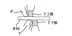
典型的には、方法は、使用者の歯間にスペーサを設けることによって所望の顎位置を決定するステップを含む。 Typically, the method comprises the step of determining the desired jaw position by providing spacers between the user's teeth.
典型的には、スペーサは、
a)使用者の舌、
b)相対的顎位置を示すマーキングを含む層状部材、
c)互いに対して移動する上部および底部アーチ・トレイ、
d)折り畳まれた紙片、
e)3mmから5mmの間の厚さ、および
f)3.5mmから4.5mmの厚さ
の少なくとも1つのものである。
Typically, the spacer is
a) User's tongue,
b) Layered members containing markings indicating relative jaw positions,
c) Top and bottom arch trays that move relative to each other,
d) Folded piece of paper,
e) at least one with a thickness between 3 mm and 5 mm, and f) with a thickness between 3.5 mm and 4.5 mm.
典型的には、方法は、
a)スペーサを使用者の歯間に設けるステップと、
b)使用者を背臥位に寝かせるステップと、
c)使用者に呼吸させるステップと、
d)呼吸中、ノイズが生じるか否かに応じて、
i)現在の位置が所望の顎位置であることを決定すること、および
ii)下顎を前進させ、c)およびd)のステップを反復すること
の少なくとも1つを行うステップとを含む。
Typically, the method is
a) Steps to install spacers between the user's teeth and
b) Steps to lay the user on his back and
c) Steps to make the user breathe and
d) Depending on whether or not noise is generated during breathing
It includes i) determining that the current position is the desired jaw position, and ii) advancing the mandible and performing at least one of steps c) and d).
典型的には、方法は、使用者の歯を、使用者の顎が少なくとも所望の顎位置にある状態で画像化することおよびスキャンすることの少なくとも1つによって形状情報を決定するステップを含む。 Typically, the method comprises the step of determining shape information by at least one of imaging and scanning the user's teeth with the user's jaw in at least the desired jaw position.
典型的には、方法は、さらに、使用者の歯を、顎が開位置および閉位置にある状態で画像化することおよびスキャンすることの少なくとも1つを含む。 Typically, the method further comprises at least one of imaging and scanning the user's teeth with the jaws in open and closed positions.
典型的には、方法は、
a)一続きの写真、
b)スキャン、
c)CTスキャン、
d)使用者の歯の3Dスキャン、および
e)円錐ビーム画像化
の少なくとも1つから形状情報を決定するステップを含む。
Typically, the method is
a) A series of photos,
b) Scan,
c) CT scan,
It comprises the steps of determining shape information from at least one of d) 3D scanning of the user's teeth and e) conical beam imaging.
典型的には、画像は、
a)使用者の歯、
b)使用者の歯の印象および/または咬合記録、および
c)印象に注入するまたは3D印刷から作り出された歯科モデル
の少なくとも1つから得られる。
Typically, the image is
a) User's teeth,
b) the impression and / or occlusal record of the user's teeth, and c) obtained from at least one of the dental models injected into the impression or produced from 3D printing.
典型的には、方法は、
a)印刷ファイルを形状にしたがって変更するステップと、
b)変更された印刷ファイルを使用して本体を製造するステップと
を含む。
Typically, the method is
a) Steps to change the print file according to the shape,
b) Includes steps to manufacture the body using the modified print file.
典型的には、方法は、
a)レジンを本体に施与し、
b)顎が所望の顎位置にある状態の使用者の歯に基づいてレジンを成形し、
c)成形されたレジンを硬化させる
ことによって少なくとも1つのインサートを製造するステップを含む。
Typically, the method is
a) Apply the resin to the main body and
b) Mold the resin based on the user's teeth with the jaw in the desired jaw position.
c) Including the step of making at least one insert by curing the molded resin.
典型的には、方法は、
a)形状情報を用いて、使用者の歯および顎のモデルである顎モデルを製造するステップと、
b)顎モデルを使用してレジンを成形するステップと
を含む。
Typically, the method is
a) Steps to manufacture a jaw model that is a model of the user's teeth and jaw using shape information,
b) Includes the step of molding the resin using the jaw model.
典型的には、方法は、硬化したレジンをトリミングすることおよび研磨することの少なくとも1つを含む。 Typically, the method comprises at least one of trimming and polishing the cured resin.
典型的には、3Dファイルからの3D印刷を使用して少なくとも1つのインサートを製造するステップを含む、請求項53から61のいずれか一項に記載の方法。 13. The method of any one of claims 53-61, comprising the steps of manufacturing at least one insert, typically using 3D printing from a 3D file.
典型的には、インサートは、
a)ポリウレタン、および
b)エチル酢酸ビニル
の少なくとも1つを使用して印刷される。
Typically, the insert is
Printed using at least one of a) polyurethane and b) vinyl acetate.
典型的には、方法は、
a)熱可塑性物質の薄いシートを顎モデル上で熱成形し、
b)熱成形されたシートを本体内に置き、
c)本体と熱成形されたシートの間のすべての空間に、同じ材料および類似の材料の少なくとも1つである、加熱された液体を充填する
ことによって少なくとも1つのインサートを製造するステップを含む。
Typically, the method is
a) Thermoform a thin sheet of thermoplastic on the jaw model and
b) Place the thermoformed sheet inside the main body and place it.
c) The step of making at least one insert by filling all the space between the body and the thermoformed sheet with a heated liquid, which is at least one of the same and similar materials.
典型的には、方法は、
a)呼吸補助装置を使用者に嵌め合わせるステップと、
b)呼吸補助装置を、使用時に
i)安定性、
ii)快適性、および
iii)呼吸ノイズ
の少なくとも1つに関して確認するステップと、
c)呼吸補助装置を必要に応じて変更するステップと
を含む。
Typically, the method is
a) The step of fitting the respiratory assist device to the user,
b) When using the respiratory assist device i) Stability,
ii) Comfort, and ii) Steps to check for at least one of respiratory noise,
c) Includes steps to change the respiratory assist device as needed.
典型的には、本体は、
a)使用者の唇間に空気を流すための少なくとも1つの第1の開口部と、
b)口腔内に設けられて、空気流が口腔の後方領域に出入りすることを可能にする2つの第2の開口部と、
c)2つのチャネルであって、各チャネルは、それぞれの前記第2の開口部と前記少なくとも1つの第1の開口部をつなげ、また、各チャネルが、少なくとも部分的に前記頬側口腔に沿って及び/又は少なくとも部分的に前記歯の間を通ることにより、鼻腔を少なくとも部分的に迂回し、健康な鼻腔および咽頭空間を複製するように作用する気道を使用者に提供する、2つのチャネルと
を備える。
Typically, the body is
a) At least one first opening for allowing air to flow between the user's lips, and
b) Two second openings provided in the oral cavity that allow airflow to enter and exit the posterior region of the oral cavity.
c) Two channels, each connecting the respective second opening to the at least one first opening, and each channel is at least partially along the buccal oral cavity. Two channels that provide the user with an airway that at least partially bypasses the nasal cavity and acts to replicate a healthy nasal cavity and pharyngeal space by passing between the teeth and / or at least partially. And.
口腔内装置の製造時に用いる方法であって、
a)所望の顎位置を決定するステップと、
b)使用者の顎が少なくとも所望の顎位置にある状態の使用者の歯の形状を示す形状情報を得るステップと、
c)形状情報を使用して口腔内装置を少なくとも部分的に製造するステップとを含む、方法。
This method is used when manufacturing an intraoral device.
a) Steps to determine the desired jaw position and
b) A step of obtaining shape information indicating the shape of the user's teeth in a state where the user's jaw is at least in a desired jaw position, and
c) A method comprising the steps of at least partially manufacturing an intraoral device using shape information.
本発明の別個の形態は限定的であるようには意図されないため、本発明の広範の形態およびそのそれぞれの特徴が独立的におよび/または連動して使用され得ることが、理解されよう。 It will be appreciated that the broad forms of the invention and their respective features can be used independently and / or in conjunction, as the distinct forms of the invention are not intended to be limiting.
本発明の例が、次に、添付の図を参照して説明される。 An example of the present invention will then be described with reference to the accompanying figures.
図1A〜図1Iを参照して、呼吸補助装置の一例を以下に説明する。 An example of the respiratory assist device will be described below with reference to FIGS. 1A to 1I.
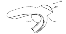
この例では、装置100は、使用者の口腔内に配置するための本体110を含む。本体110は、使用者の唇間に空気流を可能にするための少なくとも第1の開口部111と、口腔内に設けられて、口腔の後方領域への空気の流出入を可能にする2つの第2の開口部112とを含む。2つのチャネル113が設けられ、各々のチャネルは、それぞれの第2の開口部112を第1の開口部111に連結し、各々のチャネル113は、少なくとも部分的に頬側口腔に沿って及び/又は少なくとも部分的に歯の間を通り、これにより、鼻腔を少なくとも部分的に迂回し、健康な鼻腔および咽頭空間を複製するように作用する気道を使用者にもたらす。
In this example, the
この配置により、息を吸っている間、空気は、矢印121によって示すように、第1の開口部111を介して装置100に入り、チャネル113に沿って第2の開口部112まで進むことができる。第2の開口部112は、典型的には、使用者の口腔の後方に向かって、使用者の歯の舌側に設けられ、それにより、空気は、矢印122に示すように口腔の後方内へと向けられる。1つの特定例では、チャネル113および第2の開口部112は、空気が使用者の鉤切痕を流れ抜けるように設けられる。息を吐いている間、空気流は、当業者によって理解されるように逆になる。
With this arrangement, while inhaling, air can enter the
このようにして、該装置は、呼吸補助をもたらす口腔内装置を提供する。これは、睡眠中、たとえばいびきおよび睡眠時無呼吸の両方の治療に使用することができ、また、他のとき、たとえば運動中、最適な空気流を維持しやすくするために、肺気腫などの呼吸状態の治療において、およびたとえば手術中、CPR(心肺蘇生)中に空気を供給するのを補助するためなどにも使用することができる。該装置は、唇を超えて延出し、または少なくとも唇を離したまま空気流が通り抜けられる、第1の開口部111を有する。空気は、口腔の両側においてチャネル113によって画定された気道を通り抜け、第2の開口部112を通って口の後方領域内へと向けられ、舌および下顎の位置に伴う問題が回避される。より重度の場合では、第1の開口部111は、CPAP(持続的気道陽圧)機、空気供給装置、等などの外部デバイスに連結することができ、マスクと比較してより快適に患者コンプライアンスを向上させることができる。
In this way, the device provides an intraoral device that provides respiratory assistance. It can be used to treat both sleep, eg snoring and sleep apnea, and at other times, eg during exercise, breathing such as pulmonary emphysema to help maintain optimal airflow. It can also be used in the treatment of conditions and, for example, during surgery, to assist in supplying air during CPR (cardiopulmonary resuscitation). The device has a
使用者の口腔の後方部分に空気流を直接流すことには、多くの利点がある。特に、このことは、鼻腔、軟口蓋、および舌によって生じ、いびきや無呼吸事象を招き得る閉塞を回避し、結果、使用者の不快を招き得る空気流の乾燥作用を低減するのを助ける。これにより、該装置は、確実に空気の流れが妨げられないようにすることによっていびきおよび無呼吸事象を防止しつつ、着用が快適なものとなる。こうして、たとえば鼻閉塞は、装置内を流れる空気流によって迂回でき、よって鼻気道を迂回し、または、部分的な閉塞の場合は鼻気道に追加する。さらに、軟口蓋の下方または両側を流れる空気によって、その後さらなる閉塞を招き得る軟口蓋の崩壊防止を助ける。 Directly flowing airflow through the posterior part of the user's oral cavity has many advantages. In particular, this helps to avoid obstruction caused by the nasal passages, soft palate, and tongue, which can lead to snoring and apneic events, and thus reduce the drying effect of the airflow, which can cause discomfort to the user. This makes the device comfortable to wear while preventing snoring and apneic events by ensuring that the air flow is not obstructed. Thus, for example, a nasal obstruction can be circumvented by the airflow flowing through the device, thus circumventing the nasal airway or, in the case of a partial obstruction, adding to the nasal airway. In addition, the air flowing below or on both sides of the soft palate helps prevent the soft palate from collapsing, which can subsequently lead to further obstruction.
さらに、該装置は、スポーツ中、空気流が増しながらも、例えば衝撃を和らげるおよび/または吸収することによって、使用者の歯を保護する作用を持ち得る。 In addition, the device may have the effect of protecting the user's teeth, for example by cushioning and / or absorbing impact, while increasing airflow during sports.
1つの例では、本体は、3D印刷プロセスなどの付加製造を使用して製造される。これは、チャネル113の配置を、チャネル壁の厚さを最小限にしながら作り出すことを可能にするため、特に有益である。これにより、チャネルの断面積を最大限にすることができ、全体的な装置の大きさを最小限に押さえながら、空気流を補助し、それによって快適性が維持される。たとえば、付加製造の使用は、0.5mm未満、より一般的には約0.3mmまたはそれ以下のチャネル壁厚さを有する本体を可能にするが、必要に応じて、他の厚さに対応することもできることは理解されよう。こうして、標準的なプロセスを使用して作製されたアクリル製装置と比較してボリューム/かさを大きく低減し、それによって利用可能な気道サイズを最大限にしながら、使用者にとってより快適であり、かつコンプライアンスも改善される。
In one example, the body is manufactured using additive manufacturing such as a 3D printing process. This is particularly useful as it allows the placement of
さらに別の特徴を説明する。 Yet another feature will be described.
1つの例では、装置を、たとえば睡眠中または着席中など、安静時の使用に適応させるために、各々のチャネルは、少なくとも10mm2、少なくとも20mm2、少なくとも30mm2、少なくとも40mm2、および少なくとも50mm2の少なくとも1つの断面積を有する。さらに、第1の開口部および/または第2の開口部の少なくとも1つは、少なくとも50mm2、少なくとも70mm2、少なくとも90mm2、少なくとも100mm2、および少なくとも110mm2の少なくとも1つの断面積を有する。選択される寸法は、装置により部分的な気道が必要とされるのか、又は完全な気道が必要とされるのかによって、たとえば迂回する必要があるのは部分的な閉塞か完全な閉塞かを含む、広い範囲の要因に応じて変化する。さらに、これは、使用目的および関連する空気流の要求事項によって決まる。典型的には、チャネル113および/または開口部111、112の寸法は、使用者の既存の気道と併用して、利用可能な総気道が、鼻および咽頭の両方の軌道に関し健康な被験者における気道の断面積に対応するように選択される。
In one example, to adapt the device for resting use, for example during sleep or sitting, each channel is at least 10 mm 2 , at least 20 mm 2 , at least 30 mm 2 , at least 40 mm 2 , and at least 50 mm. It has at least one cross-sectional area of 2. Further, at least one of the first and / or second openings has at least one cross-sectional area of at least 50 mm 2 , at least 70 mm 2 , at least 90 mm 2 , at least 100 mm 2 , and at least 110 mm 2. The dimensions selected may include, for example, partial or complete obstruction that needs to be circumvented, depending on whether the device requires a partial airway or a complete airway. , Varies according to a wide range of factors. In addition, this depends on the intended use and associated airflow requirements. Typically, the dimensions of
いずれの場合においても、上記から、使用される断面積が、好ましい実施状況および意図される用途に応じて決定されることから、たとえば、子供、青年、または部分的な閉塞しか有さない個人にはより小さい断面積のものが使用されることが理解されよう。対照的に、大きい断面積のものは、高流量が必要とされる場合、たとえば、装置が運動中の呼吸補助のために使用される場合に使用され得る。 In any case, from the above, the cross-sectional area used will be determined according to the preferred practice and intended use, for example for children, adolescents, or individuals with only partial obstruction. It will be understood that those with a smaller cross-sectional area are used. In contrast, those with a large cross-sectional area can be used when high flow rates are required, for example when the device is used for respiratory assistance during exercise.
吸入される空気量は、活動レベルに応じて変化する。以下の表1は、安静時、運動中の男性および一流運動選手を示すものである。明確なことに、1分あたりの呼吸回数が多く、かつ呼吸中の空気量がより多いと、必要とされる空気量は増大する。
[表1]

[Table 1]
したがって、本発明の気道のサイズは、装置を有酸素活動に使用する場合大きくなる。一般的な運動の場合は安静時の使用面積の2〜3倍となり、一流運動選手ではその面積の5〜6倍となる。 Therefore, the size of the airways of the present invention increases when the device is used for aerobic activity. In the case of general exercise, it is 2 to 3 times the area used at rest, and in the case of first-class athletes, it is 5 to 6 times the area.
その結果、装置を運動時の使用に適応させるために、各々のチャネルは、少なくとも20mm2、少なくとも40mm2、少なくとも60mm2、少なくとも80mm2、少なくとも100mm2、少なくとも150mm2、少なくとも200mm2、少なくとも250mm2、および少なくとも300mm2の少なくとも1つの断面積を有する。同様に、第1の開口部および第2の開口部の少なくとも1つは、少なくとも100mm2、少なくとも140mm2、少なくとも180mm2、少なくとも200mm2、少なくとも220mm2、少なくとも330mm2、少なくとも440mm2、および少なくとも550mm2の少なくとも1つの断面積を有する。したがって、種々のチャネルおよび開口部寸法が、意図する用途に応じて臨機応変に決定され得ることが、当然ながら理解されよう。 As a result, in order to adapt the device for exercise use, each channel is at least 20 mm 2 , at least 40 mm 2 , at least 60 mm 2 , at least 80 mm 2 , at least 100 mm 2 , at least 150 mm 2 , at least 200 mm 2 , at least 250 mm. It has at least one cross-sectional area of 2 and at least 300 mm 2. Similarly, at least one of the first and second openings is at least 100 mm 2 , at least 140 mm 2 , at least 180 mm 2 , at least 200 mm 2 , at least 220 mm 2 , at least 330 mm 2 , at least 440 mm 2 , and at least. It has at least one cross-sectional area of 550 mm 2. Therefore, it will of course be understood that the various channel and opening dimensions can be flexibly determined according to the intended use.
チャネルは、多様な構成を有することができ、使用者の口腔の生体構造に応じてサイズ設定され成形され得る。典型的には、使用者の快適性を確実にしながら、利用可能な気道を最大限にするように行われる。1つの例では、以下で詳述するように、使用者の口腔を測定し、たとえば使用者の歯および/または口腔の歯科印象、一続きの写真、またはスキャン画像をとり、次いで、測定されたサイズに基づいて装置をカスタマイズすることによって達成される。一方で、一般的に、装置は、使用者に関係無く、いくつかの共通特徴を有する。 The channels can have a variety of configurations and can be sized and shaped according to the anatomy of the user's oral cavity. Typically, it is done to maximize the available airways while ensuring user comfort. In one example, the user's oral cavity was measured, eg, a dental impression of the user's teeth and / or oral cavity, a series of photographs, or scanned images, and then measured, as detailed below. Achieved by customizing the device based on size. On the other hand, in general, the device has some common features regardless of the user.
1つの例では、チャネルは、頬側口腔を介して使用者の頬と歯の間を延びる第1のチャネル部分113.1と、第1のチャネル部分と流体連通し、使用者の上顎の歯と下顎の歯の間を延びる第2のチャネル部分113.2とを含む、2つの相互連結されたチャネル部分を含む。チャネル部分は、一体的に形成され、主に例示目的のため別個の部分として参照されることが、理解されよう。いずれの場合も、この配置により、気道を使用者の歯と頬の間および使用者の歯の間に分散させることによって、使用者の快適性を維持しながら、チャネル113の断面積が最大限となる。特に、この配置により、歯間の第2のチャネル部分113.2が高くなりすぎて口を大きく開いたままでいなければならないことを回避しつつ、かつ第1のチャネル部分113.1によって頬を膨らむことも回避する。
In one example, the channel fluidly communicates with the first channel portion 113.1 extending between the user's cheek and teeth through the buccal oral cavity and the user's upper jaw teeth. Includes two interconnected channel portions, including a second channel portion 113.2 extending between the teeth of the mandible and the lower jaw. It will be appreciated that the channel parts are formed integrally and are referred to as separate parts primarily for illustrative purposes. In either case, this arrangement maximizes the cross-sectional area of
1つの例では、第1のチャネル部分113.1は、実質的に半楕円形の断面を有し、第2のチャネル部分113.2は、実質的に矩形の断面を有し、第2のチャネル部分113.2は、第1のチャネル部分113.1から横方向に内方向に延びる。第1のチャネル部分の断面を半楕円形にすることにより、湾曲した外側表面113.11が使用者の頬の内側表面に接触し、鋭敏な縁が頬と接触することを回避でき、快適性が確保される。直線状の内側表面113.12は、歯に接して配置され、それによって第1のチャネル部分の容積を最大限にする。第2のチャネル部分113.2は、矩形の断面を有し、よって、使用時は歯が、第2のチャネル部分113.2の上側面113.21および下側面113.22に接して配置される。 In one example, the first channel portion 113.1 has a substantially semi-elliptical cross section and the second channel portion 113.2 has a substantially rectangular cross section and a second The channel portion 113.2 extends laterally and inwardly from the first channel portion 113.1. By making the cross section of the first channel portion semi-elliptical, it is possible to prevent the curved outer surface 113.11 from contacting the inner surface of the user's cheek and the sharp edges from contacting the cheek for comfort. Is secured. The linear inner surface 113.12 is placed in contact with the teeth, thereby maximizing the volume of the first channel portion. The second channel portion 113.2 has a rectangular cross section, so that in use the teeth are placed in contact with the upper side surface 113.21 and the lower side surface 113.22 of the second channel portion 113.2. NS.
1つの例では、第1および第2のチャネル部分の断面積は、第1と第2の開口部111、112間で変化する。たとえば、図1A〜1Iの配置では、第1のチャネル部分は、第1の開口部111から第2の開口部112にかけて漸進的に低減し、一方で第2のチャネル部分113.2の断面積は、第1の開口部111から第2の開口部112にかけて漸進的に増大する。これにより、チャネル部分113.1、113.2を口腔内で利用可能な自然の空間にできるだけ適合させながら、チャネル113の全体的な断面積を維持することが可能になる。たとえば使用者の口腔の構成に応じて、任意のバリエーションが使用できることが理解されよう。
In one example, the cross-sectional areas of the first and second channel portions vary between the first and
こうして、チャネル113によって画定された気道は、これが人の口腔、特に、上顎の歯と下顎の歯の間ならびに歯と頬の間の利用可能な空間に適合するように成形された断面積を有する。1つの例では、第1の開口部111は、唇間の空気入口における楕円形状と、さらに、歯肉線に沿って両側の第1の大臼歯まで、次いで第1の大臼歯から装具の後方までのL字形状断面に円滑に移行する半楕円形の形状(縦方向)とを有し、それにより、気道の少なくとも一部は、この領域内では使用者の歯の間にある。
Thus, the airway defined by
1つの例では、第1の開口部は、本体に取り外し可能に装着される。この点に関して、これにより、種々のスタイルの第1の開口部を使用して、たとえば外部装置などにつなぎ合わせることを可能にすると共に、種々のサイズの第1の開口部を使用して使用者の要求に適合させることも可能にする。これはまた、開口部の容易な洗浄および/またはここに設けられたフィルタ、人工鼻、弁などの取り換えも可能にし、これは以下でより詳細に説明する。第1の開口部は、任意の適切な材料から作製可能であり、プラスチック、金属、セラミックなどを含むことができ、本体とは異なる材料を使用して作製することもできる。 In one example, the first opening is detachably attached to the body. In this regard, this allows the user to use the first openings of various styles to connect to, for example, external devices, and to use the first openings of various sizes. It also makes it possible to meet the requirements of. It also allows for easy cleaning of the openings and / or replacement of filters, artificial noses, valves, etc. provided herein, which will be described in more detail below. The first opening can be made from any suitable material, can include plastics, metals, ceramics, etc., and can also be made using a material different from the body.
1つの例では、第2の開口部は、10°から50°の間、より典型的には、20°から40°の間、好ましくは約30°で内方向に傾斜させて、空気流の口腔の出入りを補助し、特に、空気流を口腔の中心に向ける。追加的におよび/または代替的に、第2の開口部は、上顎の各側の最後または後方の歯の付近に位置決めされる。 In one example, the second opening is tilted inward between 10 ° and 50 °, more typically between 20 ° and 40 °, preferably about 30 °, to allow air flow. Assists in and out of the oral cavity, especially directing airflow to the center of the oral cavity. Additional and / or alternative, the second opening is positioned near the last or posterior teeth on each side of the maxilla.
上記で述べたように、本体110は、通常、付加製造を使用して作製され、1つの例では本体を金属、特にチタン合金および/またはコバルトクロム合金で作製する際に使用される。上記金属は高強度ポリマー、プラスチック、VeroGlaze(MED620)歯科材料などを含む、任意の適切な材料を使用してよいことが理解されよう。本体は、快適性を改善すると共に生体適合性を確実にするために、医療等級のポリマーでコーティング可能であり、1つの例では、シリコーンもしくはポリウレタンなどの医療等級のエラストマー、エポキシまたはパリレンでコーティング可能である。1つの例では、コーティングは、アクティブ・コンポジット・ガイダンス(Active Composite Guidance)を含むことができ、これは、種々の形状およびサイズを有する3次元コンポジット・レジンであり、使用者の歯に対する本体の正確な位置決めを確実するために本体に結合させることができる。コーティングは、浸漬コーティング、蒸着コーティング、または吹き付けコーティングなどの任意の適切な技術を使用して本体に施与することができ、これにより、チャネルの内部表面を含むすべての露出された表面を確実にコーティングする。このプロセスの一部として、コーティング前にプライマを本体に施与するステップを含むことができ、これにより、コーティングが本体に接着することを確実にする。
As mentioned above, the
コーティングの代替策として、またはコーティングに加えて、本体の少なくとも一部を、機械的研磨および電気化学的研磨の少なくとも1つを用いて研磨することができる。 As an alternative to coating, or in addition to coating, at least a portion of the body can be polished using at least one of mechanical and electrochemical polishing.
1つの例では、装置は、装置内を通る空気をろ過するためのフィルタ120を含む。これにより、装置内を流れる空気に混入する微粒子、花粉または他の汚染物質を除去することができるため、いびきおよび呼吸問題をさらに悪化させ得る呼吸器系への刺激を低減することができる。フィルタ120は、本体110内のいずれの場所にも配置することができるが、典型的には、第1の開口部111内に設け、必要に応じて容易に取り外したり交換することができる。フィルタは、任意の適切な形態でよく、多孔性プラスチックまたは布ベースのフィルタを含むことができ、追加機能のために追加材料を含んでもよい。たとえば、フィルタは、汚染物質/細菌をろ過して取り除くための活性炭素を含むこともできる。
In one example, the device includes a filter 120 for filtering air passing through the device. This can remove fine particles, pollen or other contaminants from the air flowing through the device, thus reducing snoring and respiratory irritation that can further exacerbate respiratory problems. The filter 120 can be placed anywhere in the
追加的におよび/または代替的に、人工鼻を設けることができ、この人工鼻は吸入された空気の湿度および温度を、吐き出された空気の熱および水分を交換することによって制御する。そのような人工鼻の例は、たとえば特許文献7に見出すことができ、したがって、これらは、これ以上詳しく説明しない。 An additional and / or alternative, an artificial nose can be provided, which controls the humidity and temperature of the inhaled air by exchanging the heat and moisture of the exhaled air. Examples of such artificial noses can be found, for example, in Patent Document 7, and therefore these are not described in further detail.
追加的にまたは代替的に、装置は、装置を通る空気の流れを調節するための弁(図示せず)を含むことができる。1つの例では、これは、第2の開口部から第1の開口部への空気の流出に抵抗するために使用され得る。これにより、呼吸の調節を補助することができ、特に、確実に吐き出しを遅くしつつ吸入を早めることができ、それによって肺内でのガス交換を最適にし、たとえば過呼吸の可能性を最小限に抑える。弁は、ボール弁、傘型弁、等などの任意の適切な形態のものになることができ、流れ制御のレベルが使用者に適切であることを確実にするように調整可能または微調整可能である。 Additionally or optionally, the device can include a valve (not shown) for regulating the flow of air through the device. In one example, it can be used to resist the outflow of air from the second opening to the first opening. This can assist in the regulation of breathing, in particular to ensure slowing exhalation and accelerating inhalation, thereby optimizing gas exchange in the lungs and minimizing the possibility of hyperventilation, for example. To suppress. The valve can be of any suitable form, such as a ball valve, umbrella valve, etc., and can be adjusted or fine-tuned to ensure that the level of flow control is appropriate for the user. Is.
本体は、下顎の歯と係合し、それによって下顎位置を維持するための舌側フランジ130を含むことができる。この点に関して、舌側フランジ130は、使用時、使用者の下顎の門歯と係合し、それによって上顎および下顎の相対位置を制御する第1の面131を含む。この点に関して、上側および下側の顎が不整合であるときに顎関節症(TMD)が生じることが知られている。これは、自然に起こる場合もあり、または負傷などに起因する場合もある。いずれの場合も、そのような顎の不整合により、上気道が変形し、舌が口腔の後方に移動することによって気道閉塞の一因となる傾向があり、ひいてはOSAおよびいびきに付随する問題を悪化させ得る。したがって、舌側フランジ300を適切な場所に設けることにより、使用者の顎を整合させることが可能になり、それによってTMDの影響を低減し、よっていびきおよびOSAの可能性がさらに低減される。以下に詳述するように、装置は、さらに、舌側フランジの第1の面を覆うように適合し得るインサートを含むことができ、当該インサートは、規定の単位で下顎位置を調整できるよう様々な厚さで提供される。
The body can include a
加えて、舌側フランジの第2の面132は、使用者の舌を受け入れるためのポケットを画定するように設けられ得る。この点において、第2の面132は、凹状形状のものであり、それにより、舌が舌側フランジ132と当接したとき、吸着効果が作り出され、使用者の舌を口腔の前方に向かって保持するのを助け、ひいては、使用者の舌の位置によって引き起こされる気道閉塞をさらに低減することを助ける。
In addition, the
したがって、この例では、舌側フランジ130は、曲線状であり、45°などの適切な角度で下方向および後方向に面して、舌の下方の舌側領域の形状に底部側および上部を適合させて舌を位置決めすることを快適に可能にする。
Thus, in this example, the
1つの例では、舌側フランジは、本体に取り外し可能に装着され、よって使用者の下顎位置の調整を可能にする。これは任意の適切な方法で達成することができるが、1つの例では、舌側フランジ130は、本体110の下側表面から突出するフランジ装着部を受け入れるためのフランジくぼみを含む。舌側フランジおよびフランジ装着部を通って延びるねじが設けられ、それにより、ねじが回転するとき、フランジくぼみ内のフランジ装着部の相対位置が調整され、それによってフランジを漸進的に移動させる。したがって、フランジ130を本体110に移動可能に装着することにより、下顎の前進の相対角度を調整し、それによって使用者にとって最適な結果をもたらすことが可能になることが理解されよう。
In one example, the lingual flange is detachably attached to the body, thus allowing the user to adjust the mandibular position. This can be achieved in any suitable way, but in one example, the
図2に示すように、追加的におよび/または代替的に、装置は、コネクタ140を含むことができ、このコネクタは、本体を下顎整復デバイスに結合させ、下顎整復デバイスは、たとえば、歯と係合するために任意選択のヒンジ143を介して保持装置142に連結されたアーム141を含む。こうして、1つの例では、コネクタ140は、可変の長さから形成された調整可能なアーム、または種々の長さの取り外し可能/交換可能なアームに結合し、本体110を第1の下顎大臼歯などの特定の歯に連結するように使用することができ、それによって下顎を前方にもっていくために1mm単位の調整を可能にする。
As shown in FIG. 2, an additional and / or alternative device can include a
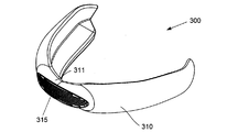
スポーツ用途などに使用するのに適した第2の実施例の装置が、図3Aから3Iに示される。この例では、200ずつ増えた類似の参照番号が、類似の特徴を示すように使用される。したがって、主に、使用者の唇を超えて突出していない、異なる開口部111の形状であることが理解されよう。これは、使用者の唇が離れるように促して適切な空気流を確実にすることを依然として補助しながら、装置による衝撃の可能性を低減することによってスポーツ場面において補助可能となる。この例では、装置はまた、衝撃が起った場合に歯に損傷を招き得るため、舌側フランジを含んでいない。また、装置は本体から延びるメッシュを含むこともでき、このメッシュは、歯肉接面を超え、舌側および唇側の少なくとも1つの使用者の歯肉溝まで延び、使用時に使用者の歯を保護する。これにより、衝撃を吸収するのを補助することができ、よって、確実に気道を維持しつつ、使用者の歯を保護することが、理解されよう。
Devices of the second embodiment suitable for use in sports applications and the like are shown in FIGS. 3A to 3I. In this example, similar reference numbers incremented by 200 are used to indicate similar features. Therefore, it will be appreciated that it is primarily the shape of the
いずれの場合も、スポーツ用途において有用であると説明してきたが、これは必須という訳ではなく、いずれの場合も、様々な構成範囲を提供できることを強調することが、理解されよう。 It has been explained that in each case it is useful in sports applications, but it is not essential and it will be appreciated that in each case it is emphasized that different configuration ranges can be provided.
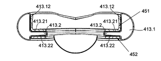
第2の実施例の装置が、図4A〜4Cに示される。この例では、300ずつ増えた類似の参照番号が、類似の特徴を示すように使用される。 The device of the second embodiment is shown in FIGS. 4A-4C. In this example, similar reference numbers incremented by 300 are used to indicate similar features.
この例では、装置400は、少なくとも1つ、より典型的には2つのインサート451、452を含み、インサートは、使用時、使用者の歯と本体410の間に配置される。インサートの断面は、チャネルの形状に適合するように、通常、鋭角およびL字形状である。特に、上側インサート451は、第2のチャネル部分413.2の上側面413.21と当接するように適合され、一方で下側インサート452は、第1のチャネル部分413.1の直線形内側表面413.12および第2のチャネル部分413.2の下側面413.22と当接するように適合される。
In this example, the
インサートは、通常、アクリル、ポリビニルシロキサン、ポリウレタンまたはエチル酢酸ビニル、別の適切なポリマーなどから形成され、任意選択により、使用者の歯に合わせてカスタマイズされ、それによって使用時の装置の快適性を最大限にする。インサートは、取り外し可能または交換可能であり、複数のインサートを提供することが可能であり、各々のインサートは、本体およびユーザの歯の少なくとも1つの異なる位置決めをもたらすように適合される。 Inserts are usually made of acrylic, polyvinylsiloxane, polyurethane or vinyl acetate, another suitable polymer, etc., and are optionally customized to the user's teeth, thereby providing equipment comfort during use. Maximize. The inserts are removable or replaceable and can provide multiple inserts, each insert adapted to provide at least one different positioning of the body and the user's teeth.
1つの特定例では、装置は、舌側フランジの少なくとも一部にわたって延びる舌側フランジ層を有するインサートを含み、舌側フランジ層の厚さは、使用者の下顎位置を調整するために用いられる。こうして、装置は、各々の使用者のための複数のインサートを含むことができ、各々のインサートは、使用者の下顎位置を公知の単位で調整するために異なる厚さの舌側フランジ層を有する。 In one particular example, the device comprises an insert having a lingual flange layer extending over at least a portion of the lingual flange, the thickness of the lingual flange layer being used to adjust the position of the user's mandible. Thus, the device can include multiple inserts for each user, each insert having a lingual flange layer of different thickness to adjust the user's mandibular position in known units. ..
インサートはまた、たとえばスポーツ用途に使用するために衝撃を保護するように適合され得る。 The insert may also be adapted to protect against impact, for example for use in sports applications.
上記で説明した装置を製造する際、通常、各使用者に合わせたカスタム装置を作り出すことを伴う。このため、方法は、通常、使用者の口腔の形状を示す形状情報を得るステップと、形状情報を使用して呼吸補助装置を製造するステップとを含む。 Manufacturing the equipment described above usually involves creating a custom device tailored to each user. For this reason, the method usually includes a step of obtaining shape information indicating the shape of the user's oral cavity and a step of manufacturing a respiratory assist device using the shape information.
形状情報は、使用者の口腔の寸法を含むことができ、使用者の口腔のCTスキャンなどのスキャンから得ることができる。または代替的に、歯科用印象、3Dモデル、使用者の歯の3Dスキャン、円錐ビーム画像化、型、口腔内スキャンのデジタル印象などから得ることができる。代替的に、当該寸法は、スマートフォンなどでとられた患者の口の一続きの写真または印象から得ることができる。 The shape information can include the dimensions of the user's oral cavity and can be obtained from a scan such as a CT scan of the user's oral cavity. Alternatively, it can be obtained from a dental impression, a 3D model, a 3D scan of the user's teeth, a conical beam imaging, a mold, a digital impression of an intraoral scan, and the like. Alternatively, the dimensions can be obtained from a series of photographs or impressions of the patient's mouth taken, such as on a smartphone.
このプロセスの一部として、当該方法は、いくつかの標準本体の1つを形状情報にしたがって選択するステップと、形状情報を使用して、選択された標準本体を変更することおよび少なくとも1つのインサートを作り出すことの少なくとも1つを行うステップとを伴うことができる。こうして、標準テンプレート本体の範囲を提供することができ、このとき、各使用者に合わせてカスタム本体を準備するために必要に応じて変更される。したがって、たとえば、6個から10個の設計などのテンプレート・デバイスの範囲は、患者の80〜90%に適合することができ、これらのテンプレート・デバイスは、歯科医または歯科技工室によって各々の患者に合わせて個々にカスタマイズされ得る。 As part of this process, the method involves selecting one of several standard bodies according to shape information, and using shape information to modify the selected standard body and at least one insert. Can be accompanied by a step of doing at least one of creating. In this way, a range of standard template bodies can be provided, which are then modified as needed to prepare a custom body for each user. Thus, a range of template devices, for example 6 to 10 designs, can be adapted to 80-90% of patients, and these template devices are each patient by the dentist or dental laboratory. Can be customized individually to suit.
変更/カスタム化は、カスタム・インサートを付加し、追加的にまたは代替的には本体のカスタム製造または仕上げを行うことによって実行され得る。カスタム製造は、本体設計を表わすテンプレート・データを得るステップと、形状情報から引き出された情報を使用して本体設計を変更するステップと、変更された本体設計を使用して変更されたテンプレート・データを生成するステップと、次いで、変更されたテンプレート・データを使用して本体を製造するステップとを含むことができる。1つの特定の情報では、変更されたテンプレート・データは、付加製造機において使用するための印刷ファイルの形態である。したがって、たとえば、このプロセスは、カスタムSTL(ステレオリソグラフィ)印刷ファイルを生成するために使用することができ、それによって本体110を各々の個人に合わせてカスタム印刷することを可能にする。こうして、たとえば、一続きの写真をソフトウェア・プログラムにロードして3D画像を引き出すことができ、次いで、この3D画像は、STLファイルを生成するために使用される。しかし、代替的には、カスタム化は、従来の技術を使用して成形する製造後プロセスになることもできる。
Modifications / customizations can be performed by adding custom inserts and, additionally or optionally, custom-manufacturing or finishing the body. Custom manufacturing is a step to obtain template data representing the main body design, a step to change the main body design using the information extracted from the shape information, and a modified template data using the changed main body design. Can include a step of generating the body and then a step of manufacturing the body using the modified template data. In one particular piece of information, the modified template data is in the form of a print file for use in the additive manufacturing machine. Thus, for example, this process can be used to generate a custom STL (stereolithography) print file, which allows the
上記の製造プロセスの一部として、下顎前進機構またはインサートなどの追加の構成要素をSTLファイル内に含み、故にデバイス内に「印刷する」ことができる。 As part of the manufacturing process described above, additional components such as mandibular advancement mechanisms or inserts can be included within the STL file and thus "printed" within the device.
1つの特定の例では、製造プロセスは、STLファイルを使用するチタンの付加製造を使用し、STLファイルは、患者の口のスキャンまたは患者の歯の印象のスキャンに適合するように適合されたデバイス設計特徴を併合したものであるが、代替的には、限定された数の標準形状を使用することができ、このとき、手動でもしくは標準的技術を使用する機械加工によって、または別個の追加のカスタム・インサートを使用することによってカスタマイズされる。 In one particular example, the manufacturing process uses additive manufacturing of titanium using an STL file, which is a device adapted to fit a scan of the patient's mouth or a scan of the impression of the patient's teeth. It is a merger of design features, but in the alternative, a limited number of standard shapes can be used, either manually or by machining using standard techniques, or in separate additions. Customized by using custom inserts.
1つの例では、本体110を製造したとき、該本体を洗浄し、次いで、医療等級のエラストマーなどの適切なポリマー材料、たとえばシリコーンもしくはポリウレタンまたはエポキシなどのポリマーなどでコーティングする。これは、手動による溶液の容器内への浸漬または吹き付けプロセスを使用して、または米国のDipTech Systems Incから入手可能なものなどの専用装置を用いて達成することができる。浸漬または吹き付けコーティング溶液の使用により、気道の内側領域のコーティングが可能になる。プライマは、接着を最適化するために使用してよく、または装置の自然な表面粗さにより機械的に取り付けするために使用してよい。コーティングの例は、それだけに限定されないが、93013カリフォルニア州、Carpinteria、Cindy Lane、1050所在のNusil TechnologyからのMED16−6606 RTV Silicone Dispersion;ドイツ国、Leverkusen 513168所在のBayer MaterialScience AGからのシームレスポリウレタンフィルムのBaymedix SD、01821マサチューセッツ州、Fortune Dr.Billerica 14所在のEpoxy Technology,Inc.からのエポキシまたはシアノアクリレートコーティングの301−2および302−3Mを含む。
In one example, when the
別の例では、本体110を製造したとき、該本体を洗浄し、次いで、パリレンなどの蒸着形態からの医療等級のポリマーなどの適切なポリマー材料でコーティングする。このような装置および材料は、USA、カリフォルニア州、Ontario所在のSpecialty Coating Systemsによって供給され得る。
In another example, when the
別の例では、本体110を製造したとき、該本体を機械的手段および/または電気化学的手段を使用して研磨する。これは、手またはベンチツールを使用する研削ビットおよび研磨パッドによるものでよい。また、フランス国、St.Priest所在の業界内で最高クラス(BinC)などからの会社からの専用の研削および電気化学処理剤を使用して達成することもできる。
In another example, when the
上記で説明したように、下顎前進装置を組み込むこともできる。1つの例では、本体110の一部として示される、固定された舌側フランジ130の形態である。代替的には、調整可能な機構が必要とされる場合、舌側フランジ130は、ねじ調整を用いてトラック上に位置決めされる別個の構成要素として設けられる。代替的には、アーム(金属またはプラスチック)を上気道装具、次いで下顎の歯の咬合領域に取り付けることができる。これらは、ねじまたは他の機械的取り付け方法を使用して患者によって容易に嵌め合わせられ得る。
As described above, a mandibular advance device can also be incorporated. In one example, it is in the form of a fixed
いずれの場合においても、上記で説明した装置は、唇間から頬溝に入り、および/または歯間、次いで親知らずの上方または後方の領域内に入り、鉤切痕を通って進み、次いで軟口蓋の近くまたはすぐ出たところの領域内に開く気道を提供する歯科インサートを提供する。これは、代替の気道を提供し、鼻孔、軟口蓋内の、または舌によって作り出された部分的な閉塞または全閉塞の衝撃を軽減するのを助け、それによってそのような閉塞の衝撃を低減し、故にいびきおよびOSAを防止する。 In each case, the device described above enters the buccal sulcus from between the lips and / or between the teeth, then into the upper or posterior region of the wisdom tooth, through the hook notch, and then on the soft palate. Provides a dental insert that provides an open airway within a near or immediate area. This provides an alternative airway and helps reduce the impact of partial or total obstruction created by the nostrils, soft palate, or tongue, thereby reducing the impact of such obstructions, Therefore, it prevents snoring and OSA.
舌側フランジの対策は、使用者の下顎を前方に移動させるために使用して、舌による閉塞の防止を助けることができ、これにより妨害の無い舌咽神径気道が維持され、このとき前進の角度は、症状の重症度に応じて制御される。たとえば、舌閉塞を取り除くために必要であれば神経筋ゾーンの耐性の極限以上まで可能である。舌フランジの凹状内側表面もまた、任意選択の舌くぼみと一緒になって、吸い込みカップとして作用して舌を前方に保持することができる。 Countermeasures for the lingual flange can be used to move the user's lower jaw forward to help prevent obstruction by the tongue, which maintains an unobstructed glossopharyngeal airway, which is then advanced. The angle of the tongue is controlled according to the severity of the symptom. For example, it is possible to exceed the limit of tolerance of the neuromuscular zone if necessary to remove the tongue obstruction. The concave inner surface of the tongue flange can also be combined with an optional tongue indentation to act as a suction cup and hold the tongue forward.
これに加えて、装置は、上側および下側の顎の整合を維持するのを補助し、TMDの影響を低減することができる。 In addition to this, the device can help maintain the alignment of the upper and lower jaws and reduce the effects of TMD.
装置はまた、舌側フランジ内に挿入されるねじを含み、装置をPSG(ポリソムノグラフィ)およびEMG(筋電図検査)と共に使用するために微調整可能になることを可能にすることができる。 The device also includes a screw that is inserted into the lingual flange, allowing the device to be fine-tuned for use with PSG (polysomnography) and EMG (electromyography). can.
上記で説明した例から、唇間から頬溝内に入り、および/または歯間、次いで後部歯または親知らずの上方または後方の領域内に入り、鉤切痕を通って進み、次いで軟口蓋の近くまたはすぐ出たところの領域内に開く気道の使用は、口腔内に挿入可能な本体を含む既存のインサートの一部として実施することができることが、理解されよう。したがって、上記で説明した例は、例示の目的ためにすぎず、限定的であるようには意図されない。 From the example described above, it enters the buccal sulcus from between the lips and / or between the teeth, then into the posterior or upper or posterior region of the wisdom tooth, through the hook notch, and then near or near the soft palate. It will be appreciated that the use of an airway that opens into the immediate area can be performed as part of an existing insert that contains a body that can be inserted into the oral cavity. Therefore, the examples described above are for illustrative purposes only and are not intended to be limiting.
したがって、上記の装置は、睡眠時無呼吸を有する人を治療することができるが(特により重度の場合)、典型的には、マスクと比較してより快適であり、故により大きいコンプライアンス率を有することが、理解されよう。この点に関して、CPAP使用者の30〜50%が、治療を開始して2年以内のノンコンプライアンス(non−compliance)/非使用者であることが示されており、さらに別の最近の研究は、口呼吸が、ノンコンプライアンスを示すものであることを示している。 Thus, although the above device can treat a person with sleep apnea (especially in more severe cases), it is typically more comfortable compared to a mask and therefore has a higher compliance rate. It will be understood to have. In this regard, 30-50% of CPAP users have been shown to be non-compliance / non-users within 2 years of starting treatment, yet another recent study has shown. , Mouth breathing indicates non-compliance.
該装置は、CPAPの有無にかかわらず、睡眠検査と一般的な家庭での使用(睡眠の質および日中の機能)によって示される睡眠を大きく改善させることができる。装置は、口渇の問題を解消し、理想的には、初期使用により過剰に唾液が分泌する件数を低減する。該装置は、着用がより快適であり、歯の摩擦、歯の移動、顎の不整合、または移動によって知覚される「口ノイズ」などの副次的影響をより軽減する。また、該装置は、歯の象牙質にいかなる損傷も引き起こさず、製造のコストをより低くし、よって、必要に応じて現行の販売価格が低減される場合、利益性を高くすることもでき、規制要件に適合する。 The device can significantly improve the sleep exhibited by sleep tests and general home use (sleep quality and daytime function) with or without CPAP. The device eliminates the problem of dry mouth and ideally reduces the number of excessive saliva production with initial use. The device is more comfortable to wear and further reduces side effects such as tooth friction, tooth movement, jaw mismatch, or "mouth noise" perceived by movement. The device can also be profitable if it does not cause any damage to the dentin of the tooth, lowering the cost of manufacture and thus, if necessary, reducing the current selling price. Meet regulatory requirements.
しかし、上記の説明は、睡眠時無呼吸およびいびきの用途に焦点を当てているが、装置の使用は、そのように限定されず、呼吸補助が必要とされる任意のシナリオにおいて適用することができる。 However, although the above description focuses on sleep apnea and snoring applications, the use of the device is not so limited and may be applied in any scenario where respiratory assistance is required. can.
たとえば、当該装置を、スポーツ用途で使用して運動選手の肺内により多くの空気を送出することによって、運動選手が、トレーニング/運動中により容易に呼吸することができる。この場合、気道は、より大きくなり得るが、基本的設計は同じである。装置は、典型的には、風邪またはアレルギーによる鼻詰まりの人の場合に良好に使用されると共に、水蒸気などの他の療法の送出を補助して、たとえばぜんそくによる詰まりおよび気道の刺激を軽減させるために使用され得る。この点に関して、内蔵フィルタの使用は、汚染物質からの刺激を低減するのを助けることができるが、制御弁の使用は、呼吸を調節するのを補助することができ、それによって呼吸効率性を改善し、呼吸困難の影響を軽減する。弁はまた、吸い込むときの空気率を制御し、次いで、吐き出しを遅くして肺内の酸素およびCO2交換を釣り合わせるのを助け、過換気または運動選手の体内の乳酸の蓄積の機会を低減することができる。また、COPD(慢性閉塞性肺疾患)または肺気腫などの肺疾患または呼吸障害を治療するために、たとえば、酸素、空気、麻酔薬、CPRなどの投与中にマスクの使用に置き換えて、または他の気道デバイスに加えて、ならびに他のときは日中活動のために使用することもできる。 For example, by using the device in sports applications to deliver more air into the athlete's lungs, the athlete can breathe more easily during training / exercise. In this case, the airways can be larger, but the basic design is the same. The device is typically used well in people with nasal congestion due to a cold or allergy, while assisting in the delivery of other therapies such as water vapor to reduce asthma congestion and airway irritation, for example. Can be used for. In this regard, the use of built-in filters can help reduce irritation from contaminants, while the use of control valves can help regulate breathing, thereby improving respiratory efficiency. Improve and reduce the effects of dyspnea. The valve also controls the rate of air when inhaling, then slows exhalation to help balance oxygen and CO 2 exchange in the lungs, reducing the chances of hyperventilation or the accumulation of lactate in the athlete's body. can do. Also, to treat lung diseases or respiratory disorders such as COPD (chronic obstructive pulmonary disease) or emphysema, replace with the use of masks during administration of, for example, oxygen, air, anesthetics, CPR, or other In addition to airway devices, it can also be used for daytime activities at other times.
上記から、装置は、歯列矯正または歯科の装具の一部を形成することができ、この場合、気道は、他の機能も有して本体内に組み込むことができることも理解されよう。 From the above, it will also be appreciated that the device can form part of an orthodontic or dental device, in which case the airway can also be incorporated into the body with other functions.
また、インサートは、歯とインサートの壁の間に空隙または空間を有するように作製することができ、それによってデバイスを着用しているときに歯の美白ゲルを使用することを可能にすることも、理解されよう。 The insert can also be made to have a gap or space between the tooth and the wall of the insert, thereby allowing the tooth whitening gel to be used while wearing the device. , Will be understood.
使用者に合わせて呼吸補助装置を製造する際に用いる方法の一例、特にカスタム呼吸補助装置を製造するための例を、図5を参照して以下に説明する。 An example of a method used in manufacturing a respiratory assist device tailored to the user, particularly an example for manufacturing a custom respiratory assist device, will be described below with reference to FIG.
この例では、ステップ500において、当該方法が所望の顎位置を決定するステップを含む。この点に関して、所望の顎位置は、呼吸補助装置が着用されているときに使用者がとる顎位置、特に、快適であり、使用者に合わせて空気流を最適化し、それによっていびきまたは他の望ましくない呼吸事象を最小限に抑える顎位置であるとみなされる。
In this example, in
所望の顎位置は、通常、咬合縦方向寸法、舌サイズ、アーチ間関係、歯の整合、顎関節機能、軟組織状態、リンパ組織、歯周状態、上顎骨アーキテクチャ、アーチ形態、口蓋深などの種々の要因の範囲に応じて、各使用者に合わせて変化する。したがって、快適性を維持しながら、舌咽頭の閉塞を取り除きやすい所望の顎位置を決定することが、典型的である。 Desired jaw positions usually vary from occlusal longitudinal dimensions, tongue size, arch-tooth relationships, tooth alignment, temporomandibular joint function, soft tissue status, lymphatic tissue, periodontal status, maxillary architecture, arch morphology, palatal depth, etc. It changes according to each user according to the range of factors. Therefore, it is typical to determine the desired jaw position where it is easy to remove the obstruction of the tongue and pharynx while maintaining comfort.
したがって、所望の顎位置は、通常、使用者の上顎および下顎の歯を、呼吸の補助装置を収容するのに十分な角度で、任意選択により、下側の顎を前進させて舌を口腔内で前方に移動させる状態で、離間させることを可能にする。 Therefore, the desired jaw position is usually at an angle sufficient to accommodate the user's maxillary and mandibular teeth to accommodate a breathing aid, and optionally the lower jaw is advanced to advance the tongue into the oral cavity. It is possible to separate it while moving it forward with.
これに続いて、ステップ510において、使用者の顎が所望の顎位置にある状態の使用者の歯の形状を示す形状情報が、得られる。これは、前に説明したように任意の適切な方法で達成することができ、この後でスキャンされる咬合印象を得るステップを含むことができるが、より典型的には、使用者の歯および顎を、顎が所望の顎位置にあるときに、たとえば、円錐ビーム断層撮影法(CBCT)、CTスキャン、口内スキャンのデジタル印象などを使用してスキャンするステップを含む。代替的には、3D画像化技術などを使用して達成することができ、このことについては、以下でより詳細に説明する。こうして、ステップ500において決定された所望の顎位置は、通常、たとえば、咬合記録材料、位置決めスペーサなどを使用して記録され、後続のスキャンプロセス中に使用することで、顎が所望の顎位置にあるときの形状情報が得られる。
Following this, in
ステップ520において、呼吸補助装置の本体は、形状情報を使用して少なくとも部分的に製造される。これは、カスタム設計された本体を作り出すステップを含むことができ、典型的には、標準テンプレート本体のSTL印刷ファイルなどを形状情報にしたがって変更するステップを含む。
In
ステップ530において、少なくとも1つのインサートが、使用者の所望の顎位置に合わせて製造されて、インサートを、使用時に使用者の歯と本体の間に少なくとも部分的に位置決めすることを可能にし、それによって装置の着用をより快適にする。これは、任意の適切な方法で達することができ、典型的には、レジンを所望の形状にした後でこれを硬化させるステップを伴う。
In
したがって、上記で説明したプロセスは、形状情報が決定される前に使用者の顎を所望の顎位置に置くステップを伴う。形状情報は、次いで、呼吸補助装置または他の口腔インプラントの本体を製造するために使用することができ、これにより、使用者に合わせて、特に、使用者の顎が所望の顎位置に保持されるように適切に構成され、よって呼吸が最適化されることを確実にする。 Therefore, the process described above involves the step of placing the user's jaw in the desired jaw position before the shape information is determined. The shape information can then be used to make the body of a respiratory aid or other oral implant, which holds the user's jaw in the desired jaw position, in particular for the user. Properly configured to ensure that breathing is optimized.
使用者に合わせて呼吸補助装置を製造する際に用いる方法の第2の例を、図5を参照して説明する。 A second example of a method used in manufacturing a respiratory assist device tailored to the user will be described with reference to FIG.
この例では、ステップ600において、所望の顎位置は、使用者の歯間にスペーサを設けることによって少なくとも部分的に決定される。スペーサの性質は、好ましい実施に応じて変化し、使用者の舌、相対顎位置を示すマーキングもしくは折り畳まれた紙片を含む層状部材、または他の適切な放射線透過性のスペーサを含むことができる。スペーサは、典型的には、使用者の上顎および下顎の歯が、確実に3mmから5mmの間、より典型的には3.5mmから4.5mmの間で離間して配置されるように設計される。しかし、間隔は使用者によって決まり、代替的間隔を適宜使用できることが理解されよう。スペーサはまた、下顎の前進を誘発させるように設計されてもよく、これは、使用者を案内するマーキングを使用することによって、スペーサの刻み目によって、または相対的に位置決め可能な本体からスペーサを形成することなどによって、任意の適切な方法で達成することができる。一部の特有の例のスペーサを、以下に説明する。別の例では、スペーサは、互いに対して移動する上部および底部のアーチ・トレイを含む。
In this example, in
第1の実施例のスペーサを、図7Aから7Cに示す。この例では、スペーサ700は、第1および第2のスペーサ本体710、720を含み、その各々は湾曲され、使用者の下顎および上顎の歯T上顎、T下顎それぞれの少なくとも一部を受け入れるためのくぼみ711、721を含む。各々のスペーサ本体710、720は、それぞれ本体の鋸歯状の縁712、722を含み、本体の鋸歯状の縁は、本体710、720の相対位置を制御することを可能にするように共働し、それによって下顎の前進の相対角度を調整することを可能にする。
Spacers of the first embodiment are shown in FIGS. 7A-7C. In this example, the
第2の実施例のスペーサを、図8Aおよび8Bに示す。この例では、スペーサ800は、上側および下側表面上にマークされた目盛を有する平坦本体810を含む。使用時、使用者は、自身の親指Tおよび人さし指Fを所望のマーキング上に置き、次いで、自身の歯と親指および人指し指を図示するように位置合わせして顎を所望の顎位置に置くことができる。
Spacers of the second embodiment are shown in FIGS. 8A and 8B. In this example, the
第2のスペーサは、所望の厚さを有するカード片またはプラスチック片の形態で提供することができる。別の例では、これは、1枚のA4の紙を図示する点線の折り畳み線に沿って折り畳むことによって達成することができ、その結果、所望の厚さを有するスペーサを生じさせる。 The second spacer can be provided in the form of a piece of card or piece of plastic having the desired thickness. In another example, this can be achieved by folding a piece of A4 paper along the dotted fold lines shown, resulting in spacers of the desired thickness.
しかし、使用者が上顎と下顎の歯の間に自身の舌を置いた時が、一般的には、両顎の正しい間隔であり、かつ下顎の適切な前進状態であるため、最初の近似として、これが所望の顎位置を決定するための好ましい方法となることが多いことに留意されたい。 However, as a first approximation, when the user places his tongue between the teeth of the upper and lower jaws, it is generally the correct spacing between the jaws and the proper advancement of the lower jaw. Note that this is often the preferred method for determining the desired jaw position.
ステップ610において、使用者の顎が、使用者の歯間に配置されたスペーサによって所望の顎位置に設けられた後、使用者は背臥位に寝かされ、その後ステップ620において呼吸する。特に、使用者は、鼻から深く呼吸するよう求められ、このとき、呼吸作用は、ステップ630において、UARS(上気道抵抗症候群)またはいびきを示す過度のノイズが存在するかどうかを決定するために査定される。ノイズが存在する場合、プロセスは、ステップ640において下顎を前進させるステップを含み、呼吸して呼吸ノイズを査定するプロセスが反復される。このプロセスは、ほとんどの呼吸ノイズが解消されるまで、または顎の前進が快適でなくなるまで続き、ノイズが解消された時点で、または顎の前進が快適でなくなった時点でプロセスを停止し、現在の位置を所望の顎位置として使用する。この位置を、スペーサを使用して、たとえば、本体710、720の相対位置、使用者の舌の位置、またはスペーサ上のマーキングに基づいて記録する。
In
所望の顎位置が決定された後、ステップ650において、この例では、使用者の歯、任意選択により顎を、CBCTスキャンなどの3Dスキャンを使用してスキャンすることによって形状情報を決定し、顎は、関連するスペーサを使用して所望の顎位置に保持される。この点において、スペーサは、放射線透過性であるため、スキャンプロセス中に使用可能である。また、スキャンは、通常、顎を開いた位置および閉じた位置で実行される。
After the desired jaw position has been determined, in
あるいは、スキャンは、1つまたは複数の口内カメラを使用して実行することができ、口内カメラは、下顎(下側アーチ)および上顎(上部アーチ)の複数の写真をマクロおよびミクロのレベルでとるために使用される。このプロセスを容易にするために、例えば、口腔、故に歯を制限なく利用するために、咬合ブロック開創鈎および鏡を含むさまざまな歯科ツールを使用することができる。 Alternatively, the scan can be performed using one or more intraoral cameras, which take multiple photographs of the lower jaw (lower arch) and upper jaw (upper arch) at the macro and micro levels. Used for. To facilitate this process, various dental tools can be used, including occlusal block open hooks and mirrors, for example to utilize the oral cavity and therefore the teeth without limitation.
スペーサを適所に配置して(また、下顎を上顎に対して適切に位置決めして)、開創鈎を所定位置に配置して歯のいくつかのセグメントまたはすべての歯の写真を複数枚とるように繰り返し、装具作製ために下顎に対する上顎の位置を画定し、記録する。次いで、画像処理技術を用いて得られた画像からスペーサを削除することができ、その後、画像は、重要となる指標点を特定するために分析される。 Place the spacer in place (and position the mandible properly with respect to the maxilla) and place the open hook in place to take multiple pictures of some segments or all teeth of the tooth. Repeatedly define and record the position of the maxilla with respect to the mandible for equipment fabrication. Spacers can then be removed from the image obtained using image processing techniques, after which the image is analyzed to identify key index points.
代替的に、所要の嵌合関係を有する歯科印象は、USA、ニューヨーク、Rochester所在のCarestream Healthからの歯科画像化システムなどの適切なコンピュータ断層撮影(CT)装置を使用して直接的にスキャン可能である。 Alternatively, dental impressions with the required mating relationship can be scanned directly using a suitable computed tomography (CT) device such as a dental imaging system from Carestream Health located in USA, NY, Rochester. Is.
続いて、重要となる指標点の場所に関する情報を用いて、必要に応じ、(CTの場合)2D DICOM画像を、必須関係にあるすべての歯の3Dモデルおよび/またはSTLファイルに転換することによって、以下で説明するステップを使用する装具作製が可能になる。この画像スキャンおよび3Dモデルへの変換は、既存の画像処理技術を使用して実行することができ、したがって、これは、これ以上詳細には説明しない。 Then, using information about the location of key indicator points, if necessary, by converting the 2D DICOM image (in the case of CT) into a 3D model and / or STL file of all the required teeth. , Allows the fabrication of equipment using the steps described below. This image scanning and conversion to a 3D model can be performed using existing image processing techniques, and therefore this is not described in further detail.
ステップ660において、スキャンデータの形態の形状情報は、製造設備に提供され、製造者が、STLファイルなどのカスタム印刷ファイルを準備することを可能にする。これは、典型的には、形状情報にしたがって印刷ファイルを変更することによって達成され、ステップ670において呼吸補助装置の本体を製造するために使用される。
In
ステップ680において、物理的顎モデルは、形状情報を使用して、使用者の顎のモデルを付加製造するために後で使用されるSTLファイルを作り出すことによって作成され得る。モデルは、典型的には、3D印刷等を使用して作り出されるプラスチックモデルである。
In
次いで、ステップ690において、1つまたは複数のインサートが、レジンを本体に施与し、顎が所望の顎位置にある状態の使用者の歯に基づいてレジンを成形し、次いで、成形されたレジンを硬化させることによって作り出される。使用されるレジンの性質は、好ましい方法によって変わり、上述したようにシリコーンレジンなどの化学的または熱硬化性レジンを含むことができる。このプロセスは、レジンを施与し、使用者に本体を口内に置かせ、レジンを噛ませることによって実行することができ、または代替的に、モデルの顎を使用して、たとえば、本体を顎モデル内に位置決めし、次いでレジンをモデルの歯を取り囲むように注入することによって実行することができる。
Then, in
モデル顎を使用してインサートを作り出すことは、スキャンステップ以外は、使用者が物理的に存在しなくとも呼吸補助装置を製造することができるため、特に有利である。したがって、このプロセスにより、嵌め合わせを実行するのに、歯科医師などの専門家の介入は必要最低限で済む。特に、通常いくつかの歯科設備の任意の場所で行われるスキャンを一度実施すると、装置を遠隔で製造することができ、次いで、仕上げられた状態で使用者に供給することができる。このことは、典型的に、たとえば最終的な使用者の歯の金型を作成し、仮に嵌め合わせし、カスタム化するなどのいくつかの異なる段階において歯科医による介入を必要とし、それによって全体的なコスト、およびインサートを得る不便性を大きく増す、従来の歯科装具嵌め合わせ技術とは対照的である。従来の技術とは異なり、上記で説明したプロセスは、主に遠隔で実施することができるため、より安価でより便利である。 Creating an insert using a model jaw is particularly advantageous because, except for the scan step, the respiratory assist device can be manufactured without the physical presence of the user. Therefore, this process requires minimal intervention by a specialist such as a dentist to perform the fit. In particular, once a scan, which is usually done anywhere in some dental equipment, can be performed once, the device can be manufactured remotely and then supplied to the user in a finished state. This typically requires dentist intervention at several different stages, such as creating, tentatively fitting, and customizing the final user's tooth mold, thereby overall. This is in contrast to traditional dental orthotic fitting techniques, which greatly increase the cost and inconvenience of obtaining inserts. Unlike conventional techniques, the process described above is cheaper and more convenient because it can be performed primarily remotely.
これに続いて、方法は、硬化したレジンをトリミングするステップおよび/または研磨するステップを含み、これにより、快適性を確実にすることができ、その後、呼吸補助装置を使用者に嵌め合わせて適切性を確実にする。特に、本装置は、典型的には、安定性および快適性について確認がなされ、それと共に使用時、呼吸ノイズが顕著であるかどうかを決定するための確認がなされる。特に、この確認は、揺れまたは持ち上がりが生じず、装置が歯肉上を擦らず、きつすぎず、歯、筋肉、または顎関節に疼痛を引き起こさないことを確実にするステップを伴う。 Following this, the method comprises trimming and / or polishing the cured resin, which can ensure comfort, after which the respiratory assist device is fitted to the user appropriately. Ensure sex. In particular, the device is typically checked for stability and comfort, as well as for determining if respiratory noise is significant during use. In particular, this confirmation involves steps to ensure that there is no shaking or lifting, the device does not rub over the gums, is not too tight, and does not cause pain in the teeth, muscles, or temporomandibular joints.
インサートの遠隔製造の代替策は、ソフトウェアを使用して、患者の歯のSTLファイルと設計された装具との間の空間を埋めることによって必要とされる構成要素の正確な3Dファイルを設計することである。この構造は、次いで、ポリウレタンまたはエチル酢酸ビニルなどのレジンから3D印刷され得る。 An alternative to remote manufacturing of inserts is to use software to design an accurate 3D file of the components required by filling the space between the STL file of the patient's teeth and the designed orthotic device. Is. This structure can then be 3D printed from a resin such as polyurethane or vinyl acetate.
したがって、この場合、該方法は、3Dファイルからの3D印刷を使用して少なくとも1つのインサートを製造することを含む。インサートは、ポリウレタンまたはエチル酢酸ビニルを使用して印刷される。 Thus, in this case, the method comprises making at least one insert using 3D printing from a 3D file. Inserts are printed using polyurethane or vinyl ethyl acetate.
代替的には、方法は、熱可塑物質の薄いシートを顎モデル上で熱成形し、熱成形されたシートを本体内に置き、本体と熱成形されたシートとの間のあらゆる空間を、同一材料および類似材料の少なくとも1つの加熱された液体で充填することによって少なくとも1つのインサートを製造するステップを含むことができる。 Alternatively, the method is to thermoform a thin sheet of thermoplastic on the jaw model, place the thermoformed sheet inside the body, and make every space between the body and the thermoformed sheet the same. It can include the step of making at least one insert by filling with at least one heated liquid of material and similar material.
呼吸補助装置の典型的な査定プロセスの例が、図9に示される。 An example of a typical assessment process for a respiratory assist device is shown in FIG.
この例では、ステップ900において、使用者は、典型的には、睡眠調査などの事前査定を受けて、使用者が睡眠中に呼吸の困難性を有しているかどうかを確定する。これは、通常、使用者が重度または軽度〜中程度のOSA910、920を患っているかどうかを決定するために用いられる。使用者が重度のOSAを患っている場合、典型的には、CPAPまたは類似の療法が薦められ、または使用者のOSAが軽度〜中程度になるまで食事療法および生活様式の変更を行う。
In this example, at step 900, the user typically undergoes a pre-assessment, such as a sleep survey, to determine if the user has respiratory difficulties during sleep. It is typically used to determine if a user has severe or mild to
使用者が軽度〜中程度のOSAを患っている場合、またはCPAPまたは類似の療法が適切でない場合、940において呼吸補助装置が薦められる。次いで、当該装置を上記で説明したプロセスを使用して製造し、嵌め合わせ、使用期間後に、950において装置の使用見直す。これは、通常、快適性、コンプライアンス、および効用を査定するステップを伴う。このプロセスは、通常、追跡調査の質問書、睡眠調査、および口腔顔面痛スクリーニングの使用を含む。 Respiratory aids are recommended at 940 if the user has mild to moderate OSA, or if CPAP or similar therapy is not appropriate. The device is then manufactured using the process described above, fitted, and after a period of use, the device is reviewed for use at 950. This usually involves steps to assess comfort, compliance, and utility. This process usually involves the use of follow-up questionnaires, sleep surveys, and orofacial pain screening.
患者にとって最適な形の治療がCPAPであるが、使用者はマスクを着用することができない、または着用することを好まない場合、使用者には装具が嵌め合わされ、この装具はCPAP機に連結されて、漏出を低減し、顔マスクの閉所恐怖症の性質を解消する。この場合、CPAP機からのチューブは、たとえば、標準的なマスクコネクタを使用して開口部111に直接的に連結され得る。1つの例では、開口部111は、市販のCPAPマスクコネクタと直接的に結び付けられて、これらを開口部111に直接的に連結できるように構成され得る。
If CPAP is the optimal form of treatment for the patient, but the user is unable or unwilling to wear a mask, the user is fitted with a device and the device is coupled to the CPAP machine. It reduces leakage and eliminates the claustrophobic nature of facial masks. In this case, the tube from the CPAP machine may be connected directly to the
見直しが肯定的である場合、PSGが、効き目をより詳細に調査するために実行され得る。代替的には、デバイスの効き目が効果的でない場合、9601において、たとえばシリコーン、ポリウレタンまたはエチル酢酸ビニルのインサートをより前進した位置に置き直すことによって下顎をより前進させるように微調整することで装置を改良することができる。これは、肯定的な結果または疼痛を引き起こさない前進の限界に達するまで継続され得る。 If the review is positive, PSG may be performed to investigate the efficacy in more detail. Alternatively, if the device does not work well, the device in 9601, for example, by repositioning the insert of silicone, polyurethane or vinyl acetate in a more advanced position to fine-tune the mandible to advance more. Can be improved. This can be continued until a positive result or the limit of advancement that does not cause pain is reached.
また、上記で説明した製造技術は、いかなる口腔または歯科装具にも適用することができ、本明細書において説明する呼吸補助装置に当てはめることに限定されないことが、理解されよう。この例では、方法は、典型的には、所望の顎位置を決定するステップと、少なくとも所望の顎位置にある顎の形状を示す形状情報を得るステップと、形状情報を使用して少なくとも部分的に口腔内装置を製造するステップとを含む。 It will also be appreciated that the manufacturing techniques described above can be applied to any oral or dental device and are not limited to the respiratory assist devices described herein. In this example, the method typically uses shape information to at least partially determine the desired jaw position, and at least obtain shape information indicating the shape of the jaw at the desired jaw position. Including the step of manufacturing an intraoral device.
上記の説明では、用語「付加製造」または「3D印刷」は、仮想上の任意の形状の三次元固体をデジタルモデルから作製するプロセスである。3D印刷は、付加プロセスを用いて達成され、ここでは材料の連続層が種々の形状で置かれる。3D印刷はまた、ほとんどが切断または穿孔などの方法(減量プロセス)による材料の除去に頼る従来の機械加工技術とは別個のものと考えられる。 In the above description, the term "additional manufacturing" or "3D printing" is the process of creating a virtual three-dimensional solid of any shape from a digital model. 3D printing is achieved using an addition process, where continuous layers of material are placed in various shapes. 3D printing is also considered to be separate from traditional machining techniques that rely mostly on the removal of material by methods such as cutting or perforation (weight loss process).
3D印刷機は、コンピュータ制御の下で付加プロセスを行うことができる限定されたタイプの産業ロボットである。印刷を実行するために、機械は、STLファイルから設計を読み取り、液体、粉末、紙、またはシート材料の連続層を置いて一続きの断面からモデルを築く。CADモデルからの仮想断面に対応するこれらの層は、接合され、または自動的に融合されて最終形状を作り出す。この技術の主な利点は、ほとんどあらゆる形状または幾何学的特徴を作り出すことができる能力である。 A 3D printer is a limited type of industrial robot capable of performing additional processes under computer control. To perform printing, the machine reads the design from the STL file, places a continuous layer of liquid, powder, paper, or sheet material and builds a model from a series of cross sections. These layers corresponding to the virtual cross sections from the CAD model are joined or automatically fused to create the final shape. The main advantage of this technique is the ability to create almost any shape or geometric feature.
機械、技術、および付加製造から作製されたさまざまな部分は、現在、ポリマー、金属、しっくい、およびセラミックにおけるさまざまな用途に合わせて市販されている。これらは、アーキテクチャ、構造(AEC)、工業設計、自動車、航空宇宙、軍事、工学、土木工学、歯科および医療業界、生命工学(人体組織置換)、ファッション、履物、ジュエリ、メガネ、教育、地理情報システム、食品、および数多くの他の分野を含む。 Various parts made from machinery, technology, and additive manufacturing are now commercially available for a variety of applications in polymers, metals, plaster, and ceramics. These are Architecture, Structure (AEC), Industrial Design, Automotive, Aerospace, Military, Engineering, Civil Engineering, Dental and Medical Industry, Biotechnology (Human Tissue Replacement), Fashion, Footwear, Jewelery, Glasses, Education, Geographic Information Includes systems, food, and many other areas.
金属に関して、汎用的な用語「付加製造」に対するいくつかのバリエーションが存在し、各々の機械メーカは、この技術の独自の特定のバージョンに自らの名前を付与している。これらは、電子ビーム自由形状造形法(Electron Beam Freeform Fabrication:EBF3)を使用するワイヤ、直接金属レーザ焼結法(Direct metal laser sintering:DMLS)、電子ビーム溶融法(Electron−beam melting:EBM)、選択的レーザ溶融法(Selective laser melting:SLM)、および選択的レーザ焼結法(Selective laser sintering:SLS)を使用する粒状金属を含む。 With respect to metals, there are several variations to the general term "addition manufacturing", and each machine maker gives its own name to a particular version of this technology. These include wires using the Electron Beam Freeform Fabrication (EBF3), direct metal laser sintering (DMLS), and electron beam melting (Electron-beam Melting): E. Includes granular metals using Selective Laser Melting (SLM) and Selective Laser Sintering (SLS).
本発明の装置は、スウェーデン、Molndal所在のArcam ABからの機械を使用して電子ビーム溶融法を使用して製造される。この技術は、強力な電子ビーム(最大3500W)を使用して、「電子ビーム溶融法」(EBM)プロセスを使用して金属粉末を層ごとに構築する。EBM技術は、複雑な幾何学形状を、定義された3DCADコンピュータソフトウェアから最大80cm3/時間の速度で生産することができる。各々の金属粉末層は、3D CADモデルによって定義された正確な形状になるように溶解される。電子ビームは、光学式および可動式の機械的部分ではなく電磁コイルによって管理され、これは、非常に良好なビーム制御および極めて高速のビーム並進を可能にすると言われている。EBM技術はまた、高い溶解能力および最終的な高い生産性を可能にする高エネルギービームも提供する。 The apparatus of the present invention is manufactured using an electron beam melting method using a machine from Arcam AB located in Mölndal, Sweden. This technique uses a powerful electron beam (up to 3500 W) to build metal powder layer by layer using an "electron beam melting method" (EBM) process. EBM technology can produce complex geometric shapes from defined 3D CAD computer software at speeds of up to 80 cm 3 / hour. Each metal powder layer is melted to the exact shape defined by the 3D CAD model. The electron beam is controlled by an electromagnetic coil rather than an optical and movable mechanical part, which is said to enable very good beam control and extremely fast beam translation. EBM technology also provides a high energy beam that allows for high melting capacity and ultimate high productivity.
EBMは本明細書において提案されたデバイス設計に使用されたが、他の付加製造機を使用して類似の設計を生み出すことができる。 EBM has been used in the device design proposed herein, but other additive manufacturing machines can be used to produce similar designs.
当業者は、数多くの変形形態および改変形態が明らかになることを理解するであろう。当業者に明らかになるすべてのそのような変形形態および改変形態は、説明する前に本発明がおおむね明らかになる本発明の趣旨および範囲に含まれるように考えられなければならない。 Those skilled in the art will appreciate that numerous variants and variants will be revealed. All such variants and modifications that will be apparent to those of skill in the art must be considered to be included in the spirit and scope of the invention to which the invention becomes largely apparent before being described.
したがって、たとえば、気道はまた、弾性前進のための装具、コネクタによる前進、舌保持デバイス、両顎固定装具、両顎閉塞装具などを含む既存の下顎前進デバイスなどの他の形態の装置に組み込むこともできることが理解されよう。上記の説明した構成は、したがって、例示の目的のためであり、限定的であるようには意図されない。 Thus, for example, the airway may also be incorporated into other forms of equipment such as existing lower jaw advancement devices, including elastic advancement devices, connector advancement, tongue holding devices, bimaxillary fixation devices, bimaxillary obstruction devices, and the like. It will be understood that it can also be done. The configurations described above are therefore for illustrative purposes only and are not intended to be limiting.
100、400 装置
110 本体
111 第1の開口部
112 第2の開口部
113 2つのチャネル
113.1 第1のチャネル部分
113.11 外側表面
113.12 内側表面
113.2 第2のチャネル部分
113.21 上側面
113.22 下側面
120 フィルタ
121、122 矢印
130 舌側フランジ
131 第1の面
132 第2の面
140 コネクタ
141 アーム
142 保持装置
143 任意選択のヒンジ
410 本体
413.1 第1のチャネル部分
413.12 線形内側表面
413.2 第2のチャネル部分
413.21 上側面
413.22 下側面
451 上側インサート
452 下側インサート
700、800 スペーサ
710 第1のスペーサ本体
720 第2のスペーサ本体
711、721 くぼみ
712、722 鋸歯状の縁
810 平坦本体
500、510、520、530、600、610、620、630、640、650、660、670、680、690、900、910、920、930、940、950、960 ステップ
100, 400
Claims (12)
a)使用者の唇間に空気を流すための少なくとも1つの第1の開口部と、
b)前記口腔内に設けられ、前記口腔の後方領域での空気の流出入を可能にする2つの第2の開口部と、
c)2つのチャネルであって、各チャネルは流体連通し、それぞれの前記第2の開口部と前記少なくとも1つの第1の開口部をつなげ、また、各チャネルが、実質的に半楕円形の断面を有し且つ少なくとも部分的に頬側口腔に沿って延びる第1のチャネル部分と、実質的に矩形の断面を有し且つ少なくとも部分的に使用者の上顎歯と下顎歯の間を延びる第2のチャネル部分の少なくとも1つを含むことにより、鼻腔、軟口蓋、および舌を少なくとも部分的に迂回する気道を使用者に提供し、且つ
i)前記本体がチャネル壁を画定し、
ii)前記本体が付加製造を使用して作製される製造品であって、前記チャネル壁の少なくとも一部が0.5mm未満の最小限の厚さであり、
iii)前記チャネルが画定する気道によって使用者の上顎の歯と下顎の歯の間及び/又は歯と頬の間の利用可能な空間が最大限になるように、前記使用者の前記口腔の生体構造にしたがって前記2つのチャネルの少なくとも1つのチャネルの断面形状および断面積が前記第1の開口部から前記第2の開口部にかけて変化し、
iiii)各チャネルの断面積が少なくとも40mm2である、2つのチャネルと
を備える、呼吸を補助するための装置。 A device for assisting breathing, including a body consisting of a continuous layer for placement in the user's oral cavity, said body.
a) At least one first opening for allowing air to flow between the user's lips, and
b) Two second openings provided in the oral cavity that allow air inflow and outflow in the posterior region of the oral cavity.
c) Two channels, each channel fluidized , connecting each said second opening to said at least one first opening, and each channel being substantially semi-elliptical. A first channel portion having a cross section and at least partially extending along the buccal oral cavity and a second having a substantially rectangular cross section and at least partially extending between the user's maxillary and mandibular teeth. by including at least one of the second channel portion, to provide nasal, soft palate, and the airway to at least partially bypass the tongue to the user, and
i) The body defines the channel wall and
ii) The main body is a manufactured product manufactured by using additive manufacturing, and at least a part of the channel wall has a minimum thickness of less than 0.5 mm.
iii) The living body of the oral cavity of the user so that the airway defined by the channel maximizes the available space between the teeth of the maxilla and / or the teeth of the user. cross-sectional shape and cross sectional area of the at least one channel of the two channels is changed toward the second opening from the first opening according to the structure,
iii ) A device for assisting breathing, comprising two channels having a cross-sectional area of at least 40 mm 2 for each channel.
前記第1のチャネル部分の断面積が、前記第1の開口部から前記第2の開口部にかけて低減し、且つ、前記第2のチャネル部分の断面積が、前記第1の開口部から前記第2の開口部にかけて増大している、請求項1に記載の装置。 It said second channel portion in fluid communication with said first channel portion, said second channel portion, extends Beauty inward laterally from said first channel portion,
Sectional area of the pre-Symbol first channel portion is reduced from the first opening toward the second opening, and, the cross-sectional area of the second channel portion, said from the first opening The device according to claim 1, which is increasing toward the second opening.
a)i)10°から50°の間、
ii)20°から40°の間、および
iii)約30°
の少なくとも1つの角度で前記口腔の中心方向に傾斜され、
且つ、
b)前記使用者の上顎の各側の最後または後方の歯の付近に位置決めされる、
請求項1から3のいずれか一項に記載の装置。 The second opening is from the coronal or frontal plane a) i) between 10 ° and 50 °.
ii) between 20 ° and 40 °, and ii) about 30 °
Tilt toward the center of the oral cavity at at least one angle of
and,
b) Positioned near the last or posterior teeth on each side of the user's maxilla.
Apparatus according to any one of the請Motomeko 1 3.
a)i)金属、
ii)チタン合金、
iii)高強度ポリマー、および
iv)コバルトクロム合金
の少なくとも1つから作製され、
且つ、
b)i)医療等級のポリマー、
ii)医療等級のエラストマー
iii)シリコーン、
iv)ポリウレタン、
v)エポキシ、および
vi)パリレン
の少なくとも1つでコーティングされ、
且つ、
c)機械的研磨および電気化学的研磨の少なくとも1つを使用して研磨される、
請求項1に記載の装置。 The main body
a) i) Metal,
ii) Titanium alloy,
iii) made from at least one of high-strength polymers and iv) cobalt-chromium alloys,
and,
b) i) Medical grade polymer,
ii) Medical grade elastomer ii) Silicone,
iv) Polyurethane,
Coated with at least one of v) epoxy and vi) parylene,
and,
c) Polished using at least one of mechanical and electrochemical polishing ,
The apparatus according to 請Motomeko 1.
a)前記インサートが、使用者の歯に合わせてカスタマイズされ、
b)前記インサートが、取り外し可能および交換可能の少なくとも1つであり、
c)前記装置が、各使用者のための複数のインサートを含み、各々のインサートは、本体および使用者の歯の少なくとも1つの異なる配置に適応し、
d)前記インサートが、衝撃を吸収するように適応され、
e)前記インサートが、
i)金属、
ii)セラミック、
iii)ポリマー、
iv)ポリビニルシロキサン、
v)ポリウレタン、および
vi)エチル酢酸ビニル
の少なくとも1つから作製される
請求項1から5のいずれか一項に記載の装置。 The device comprises at least one insert, which is at least partially positioned between the user's teeth and the body during use, and a) the insert is customized for the user's teeth. Being done
b) The insert is at least one removable and replaceable.
c) The device comprises multiple inserts for each user, each insert adapting to at least one different arrangement of the body and the user's teeth.
d) The insert is adapted to absorb impact
e) The insert
i) Metal,
ii) Ceramic,
iii) Polymer,
iv) Polyvinylsiloxane,
v) a polyurethane, and vi) from at least one of ethyl vinyl acetate Ru produced
Apparatus according to any one of the請Motomeko 1 5.
a)前記装置を流れる空気をろ過するためのフィルタで、
b)前記少なくとも1つの第1の開口部内に位置決めされるフィルタを含み、
c)吸入空気と吐き出し空気の間で熱および水分の少なくとも1つを交換するための交換器で、
d)前記少なくとも1つの第1の開口部内に位置決めされる交換器を含み、
e)前記装置に出入りする空気の流れを調節するための弁であって、前記第2の開口部から前記第1の開口部への空気の流れに抵抗するための弁
を含む、請求項1から6のいずれか一項に記載の装置。 The device
a) A filter for filtering the air flowing through the device.
b) a filter positioned in said at least one first opening portion,
c) A switch for exchanging at least one of heat and moisture between inspiratory air and exhaled air.
d) wherein the exchanger is positioned in said at least one first opening portion,
a valve for regulating the flow of air into and out of e) said apparatus, said second valve to resist flow of air from the opening to the first opening
The device according to any one of claims 1 to 6 , comprising the above.
a)前記使用者の唇間に空気を流すための少なくとも1つの第1の開口部と、
b)前記口腔内に設けられて、前記口腔の後方領域での空気の流出入を可能にする2つの第2の開口部と、
c)2つのチャネルであって、各チャネルは流体連通し、それぞれの前記第2の開口部と前記少なくとも1つの第1の開口部をつなげ、また、各チャネルが、実質的に半楕円形の断面を有し且つ少なくとも部分的に頬側口腔に沿って延びる第1のチャネル部分と、実質的に矩形の断面を有し且つ少なくとも部分的に使用者の上顎歯と下顎歯の間を延びる第2のチャネル部分の少なくとも1つを含むことにより、鼻腔、軟口蓋、および舌を少なくとも部分的に迂回する気道を使用者に提供し、且つ
i)前記本体がチャネル壁を画定し、前記チャネル壁の少なくとも一部が0.5mm未満の最小限の厚さであり、
ii)前記チャネルが画定する気道によって使用者の上顎の歯と下顎の歯の間及び/又は歯と頬の間の利用可能な空間が最大限になるように、前記使用者の前記口腔の生体構造にしたがって前記2つのチャネルの少なくとも1つのチャネルの断面形状および断面積が前記第1の開口部から前記第2の開口部にかけて変化し、
iii)各チャネルの断面積が少なくとも40mm2である、2つのチャネルと
を含む、使用者に合わせた呼吸補助装置を製造するための方法。 A method for manufacturing a respiratory assist device tailored to the user, comprising the step of using additive manufacturing to create a body consisting of a continuous layer for placement in the user's oral cavity.
a) At least one first opening for allowing air to flow between the user's lips, and
b) Two second openings provided in the oral cavity to allow air inflow and outflow in the posterior region of the oral cavity.
c) Two channels, each channel fluidized , connecting each said second opening to said at least one first opening, and each channel being substantially semi-elliptical. A first channel portion having a cross section and at least partially extending along the buccal oral cavity and a second having a substantially rectangular cross section and at least partially extending between the user's maxillary and mandibular teeth. by including at least one of the second channel portion, to provide nasal, soft palate, and the airway to at least partially bypass the tongue to the user, and
i) The body defines the channel wall, at least a portion of the channel wall having a minimum thickness of less than 0.5 mm.
ii ) The living body of the oral cavity of the user so that the airway defined by the channel maximizes the available space between the teeth of the maxilla and / or the teeth of the user. cross-sectional shape and cross sectional area of the at least one channel of the two channels is changed toward the second opening from the first opening according to the structure,
iii ) A method for manufacturing a user-tailored respiratory assist device, comprising two channels having a cross-sectional area of at least 40 mm 2 for each channel.
i)金属、
ii)チタン合金、
iii)高強度ポリマー、および
iv)コバルトクロム合金
の少なくとも1つから作製され、
b)前記方法が、前記本体にコーティングを施すステップ、前記本体の内側表面にコーティングを施すステップ、
i)浸漬コーティング、
ii)吹き付けコーティング、および
iii)蒸着コーティング
の少なくとも1つによって前記本体をコーティングするステップ
の少なくとも1つを含み、
c)前記方法が、コーティング前にプライマを前記本体に施与するステップ、ならびに、機械的研磨および電気化学的研磨の少なくとも1つを使用して前記本体の少なくとも一部を研磨するステップ、の少なくとも1つを含む、請求項9に記載の方法。 a) The main body
i) Metal,
ii) Titanium alloy,
iii) made from at least one of high-strength polymers and iv) cobalt-chromium alloys,
b) said method comprising steps of applying a coating to the body, before Symbol steps of applying a coating to an inner surface of the body,
i ) Immersion coating,
The step of coating the body with at least one of ii) spray coating and ii) vapor deposition coating.
Including at least one of
c) the method, steps of applying to the body a primer prior to coating, and the step of polishing at least a portion of the body using at least one of mechanical polishing and electrochemical polishing, the 9. The method of claim 9, comprising at least one.
a)前記使用者の口腔の形状および寸法の少なくとも1つを示す形状情報を得るステップと、
b)前記形状情報を使用して前記呼吸補助装置を製造するステップと
を含み、且つ、前記方法が、
i)歯科印象、
ii)患者の口の一続きの写真、
iii)スキャン、
iv)CTスキャン、
v)前記使用者の歯の3Dスキャン、
vi)円錐ビーム画像化、および
vii)スマートフォンで撮影した前記患者の口の一続きの写真または印象であって、前記一続きの写真はその後STLファイルを含む3D画像を得るためにソフトウェア・プログラムにロードされる、一続きの写真または印象の少なくとも1つから前記形状情報を得るステップを含む、請求項10に記載の方法。 The above method
a) A step of obtaining shape information indicating at least one of the shape and dimensions of the user's oral cavity .
b ) With the step of manufacturing the respiratory assist device using the shape information
And the above method
i) Dental impression,
ii) A series of photographs of the patient's mouth,
iii) Scan,
iv) CT scan,
v) 3D scan of the user's teeth,
vi) Conical beam imaging, and vii) A series of photographs or impressions of the patient's mouth taken with a smartphone, the sequence of photographs then in a software program to obtain a 3D image containing an STL file. loaded, including steps for obtaining the shape information from at least one series of photos or impression the method of claim 10.
a)いくつかの標準本体の1つを前記形状情報にしたがって選択するステップと、
b)前記形状情報を用いて、
i)選択された標準本体を変更すること、および
ii)少なくとも1つのインサートを作製すること
のうち少なくとも1つを行うステップと
を含む、請求項11に記載の方法。 The above method
a) The step of selecting one of several standard bodies according to the shape information,
b) Using the shape information,
i) selection altering the-option is standard body, and ii) a step of performing at least one of making a least one insert A method according to claim 11.
Applications Claiming Priority (7)
| Application Number | Priority Date | Filing Date | Title |
|---|---|---|---|
| AU2014901181A AU2014901181A0 (en) | 2014-04-01 | Breathing assist device | |
| AU2014901181 | 2014-04-01 | ||
| AU2014901655A AU2014901655A0 (en) | 2014-05-06 | Breathing assist device | |
| AU2014901655 | 2014-05-06 | ||
| AU2014903083 | 2014-08-08 | ||
| AU2014903083A AU2014903083A0 (en) | 2014-08-08 | Breathing assist device | |
| PCT/AU2015/050144 WO2015149127A1 (en) | 2014-04-01 | 2015-03-31 | Breathing assist device |
Publications (3)
| Publication Number | Publication Date |
|---|---|
| JP2017509446A JP2017509446A (en) | 2017-04-06 |
| JP2017509446A5 JP2017509446A5 (en) | 2018-05-17 |
| JP6966839B2 true JP6966839B2 (en) | 2021-11-17 |
Family
ID=54239140
Family Applications (1)
| Application Number | Title | Priority Date | Filing Date |
|---|---|---|---|
| JP2016560790A Active JP6966839B2 (en) | 2014-04-01 | 2015-03-31 | Breathing aid |
Country Status (9)
| Country | Link |
|---|---|
| US (2) | US10632010B2 (en) |
| EP (1) | EP3125836B1 (en) |
| JP (1) | JP6966839B2 (en) |
| KR (1) | KR102264125B1 (en) |
| CN (2) | CN110680595B (en) |
| AU (2) | AU2015240431B2 (en) |
| CA (2) | CA3193175A1 (en) |
| DK (1) | DK3125836T3 (en) |
| WO (1) | WO2015149127A1 (en) |
Families Citing this family (50)
| Publication number | Priority date | Publication date | Assignee | Title |
|---|---|---|---|---|
| USD333433S (en) * | 1991-04-22 | 1993-02-23 | Colgate-Palmolive Company | Combined bottle and cap |
| US11129746B2 (en) | 2010-06-23 | 2021-09-28 | Dental Choice Holdings Llc | Method and oral appliance for improving air intake and reducing bruxism |
| DE202014010625U1 (en) * | 2013-01-11 | 2016-03-03 | Somnics, Inc. | Oral device for eliminating air space in the oral cavity |
| US9925440B2 (en) | 2014-05-13 | 2018-03-27 | Bauer Hockey, Llc | Sporting goods including microlattice structures |
| US10328225B2 (en) | 2015-10-20 | 2019-06-25 | Garner Geniothrust Llc | Dental appliance apparatus and respiratory performance |
| US20170224441A1 (en) | 2016-02-06 | 2017-08-10 | Margaret Anderson | System and method for treating sleep apnea while straightening teeth |
| CN206880919U (en) * | 2016-03-30 | 2018-01-16 | 奥温特斯医疗有限公司 | Equipment for providing Respiration assistance |
| CN109789330A (en) | 2016-03-30 | 2019-05-21 | P3竞技股份有限公司 | Air flue and oxygen promote the increasing material printing of bite |
| CN107789114B (en) * | 2016-08-30 | 2019-11-12 | 太旸科技国际股份有限公司 | The method of adjustment of sleep-respiratory facing |
| JP2019528990A (en) * | 2016-10-10 | 2019-10-17 | オーベンタス・メディカル・リミテッドOventus Medical Limited | Respiratory assist system including oral appliance and connector system thereof |
| EP3530231A4 (en) * | 2016-10-20 | 2020-09-23 | DIO Corporation | Dental retractor |
| US20190320977A1 (en) * | 2016-11-30 | 2019-10-24 | Oventus Medical Limited | Oral appliance monitoring |
| DE102017102101A1 (en) * | 2017-02-03 | 2018-08-09 | Dreve-Dentamid Gmbh | Tooth protector |
| EP3681431A4 (en) * | 2017-09-13 | 2021-09-22 | Christopher John Farrell | An oral training appliance |
| WO2019060624A2 (en) * | 2017-09-22 | 2019-03-28 | Shah Mamta Ketan | Systems, methods, and devices for treating mouth and jaw disorders |
| CA181446S (en) | 2017-11-21 | 2019-06-06 | Farrell Christopher John | Oral appliance |
| WO2019133781A1 (en) * | 2017-12-28 | 2019-07-04 | Mueller James F | Athletic mouthguard with lung exerciser |
| KR20210008830A (en) | 2018-03-12 | 2021-01-25 | 오벤투스 메디칼 리미티드 | Oral instruments and valve arrangement |
| USD862705S1 (en) * | 2018-04-30 | 2019-10-08 | Shanghai Mugang Medical Technology Ltd. | Dental appliance |
| EP3787574A4 (en) * | 2018-05-02 | 2022-01-19 | Oventus Medical Limited | Breathing assistance oral apparatus |
| AU201813151S (en) | 2018-05-25 | 2019-01-24 | An oral appliance | |
| USD909586S1 (en) | 2018-05-25 | 2021-02-02 | Christopher John Farrell | Oral appliance |
| AU201813153S (en) | 2018-05-25 | 2019-01-25 | An oral appliance | |
| US11083956B1 (en) | 2018-05-25 | 2021-08-10 | Dental Choice Holdings Llc | Customizable guard |
| EP4279110A3 (en) | 2018-07-20 | 2024-01-24 | Myosa Pty Ltd | Oral appliance |
| CN108670533A (en) * | 2018-07-25 | 2018-10-19 | 湖南省天骑医学新技术股份有限公司 | A kind of metal snore relieving facing and preparation method thereof |
| CN108992236A (en) * | 2018-08-07 | 2018-12-14 | 佛山科学技术学院 | A kind of device for preventing snoring |
| USD924389S1 (en) * | 2018-08-28 | 2021-07-06 | Chemomouthpiece, Llc | Mouthpiece |
| KR102098391B1 (en) * | 2018-10-23 | 2020-04-07 | 박동신 | hyperdyhamia brace |
| KR102128382B1 (en) * | 2018-11-01 | 2020-06-30 | 스타일치과기공 주식회사 | Oral airway, method for manufacturing threof and respiration monitoring system |
| CA3026695C (en) * | 2018-12-05 | 2021-09-07 | Imd Research Inc. | Single arch device for gradual mandibular advancement |
| KR101997238B1 (en) * | 2019-01-14 | 2019-07-05 | 김희윤 | Device for snoring prevention |
| CA188766S (en) | 2019-01-25 | 2020-12-21 | Farrell Dr Christopher John | Oral appliance |
| USD875237S1 (en) * | 2019-04-18 | 2020-02-11 | Firas Kasem Ghazzawi | Resistance breathing device |
| US20220222823A1 (en) | 2019-05-20 | 2022-07-14 | Commonwealth Scientific And Industrial Research Organisation | Prediction and intervention of obstructive sleep apnoea |
| WO2020232550A1 (en) | 2019-05-21 | 2020-11-26 | Bauer Hockey Ltd. | Helmets comprising additively-manufactured components |
| US11285035B2 (en) | 2019-07-19 | 2022-03-29 | Dental Choice Holdings Llc | Single arch dental device and method of manufacture |
| TR201911545A2 (en) * | 2019-07-31 | 2021-02-22 | Tobb Ekonomi Ve Teknoloji Ueniversitesi | MANUFACTURING METHOD OF A PROTECTION GEAR |
| CA193365S (en) | 2019-08-27 | 2022-01-11 | Myosa Pty Ltd | Oral appliance |
| CA194146S (en) | 2019-10-11 | 2022-01-12 | Farrell Christopher John | Oral appliance |
| KR102085779B1 (en) * | 2019-11-11 | 2020-03-06 | 정다이 | Apparatus for making a customized snoring and apnea prevention device |
| CN110960764B (en) * | 2019-12-05 | 2020-09-29 | 吉林大学 | Artificial respiration device for cardiology department nursing |
| KR102358631B1 (en) * | 2020-02-14 | 2022-02-10 | 주식회사 함바이오텍 | System and method for dental tongue training service |
| US11420105B2 (en) | 2020-03-04 | 2022-08-23 | Custom Club, Inc. | Oral device having wedges and method of manufacture |
| US11110192B1 (en) | 2020-03-06 | 2021-09-07 | Custom Club, Inc. | Oral device container and oral device sanitation system |
| US11185148B2 (en) | 2020-03-06 | 2021-11-30 | Custom Club, Inc. | Oral device container and oral device container and bottle assembly |
| CA202322S (en) | 2020-10-08 | 2024-03-12 | Myosa Pty Ltd | Oral appliance |
| KR102613153B1 (en) * | 2021-09-24 | 2023-12-13 | 주식회사 뉴마핏 | A device for assisting to breath |
| KR20230064666A (en) * | 2021-11-03 | 2023-05-11 | (주) 케이제이 메디텍 | Method for manufacturing a customized maxilofacial forming plate using 3d printing technology and maxilofacial forming plate manufactured accordingly |
| WO2024003795A1 (en) * | 2022-06-29 | 2024-01-04 | 11584022 Canada Inc. | Biopolymer compositions for use in agriculture |
Family Cites Families (79)
| Publication number | Priority date | Publication date | Assignee | Title |
|---|---|---|---|---|
| US2521039A (en) * | 1949-03-16 | 1950-09-05 | Victor H Carpenter | Tooth guard |
| US2820457A (en) | 1955-01-14 | 1958-01-21 | John W Phillips | Positioning retainer for oro-tracheal tubes |
| US4304227A (en) | 1978-03-03 | 1981-12-08 | Samelson Charles F | Device for treatment of snoring, bruxism or for avoidance of sleep apnea |
| US4169473A (en) * | 1978-03-03 | 1979-10-02 | Samelson Charles F | Anti-snoring and anti-bruxism device |
| US4170230A (en) | 1978-04-14 | 1979-10-09 | Nelson Byron G | Breathing apparatus |
| US4289127A (en) | 1979-10-29 | 1981-09-15 | Nelson Byron G | Breathing apparatus stabilizer |
| US4676240A (en) | 1985-09-09 | 1987-06-30 | Gardy Victor R | Tongue locking device to minimize effects of sleep apnea and to reduce snoring |
| US5092346A (en) * | 1987-10-13 | 1992-03-03 | Hays & Meade, Inc. | Dental orthosis for alleviation of snoring |
| FI87625C (en) * | 1990-12-28 | 1993-02-10 | Olavi Ebeling | ANDNINGSMASK |
| US5067896A (en) | 1991-04-24 | 1991-11-26 | Marcel Korn | Orthodontic appliance |
| US5313960A (en) * | 1992-11-04 | 1994-05-24 | Marc S. Bernstein | Apparatus and method for reducing snoring and method of making same |
| US5465734A (en) * | 1994-01-12 | 1995-11-14 | Snorex, Inc. | Adjustable tongue positioning device and method |
| US5954048A (en) | 1994-06-03 | 1999-09-21 | Thornton; W. Keith | Device and method for improving breathing |
| US5537994A (en) | 1994-06-03 | 1996-07-23 | Thornton; W. Keith | Combination face mask and dental device for improved breathing during sleep |
| US5983892A (en) | 1994-06-03 | 1999-11-16 | Thornton; W. Keith | Device for improving breathing |
| US5792067A (en) | 1995-11-21 | 1998-08-11 | Karell; Manuel L. | Apparatus and method for mitigating sleep and other disorders through electromuscular stimulation |
| US6055989A (en) | 1996-03-21 | 2000-05-02 | Robert D. Rehnke | Method for surgical dissection, sizing and expansion |
| FR2752725B1 (en) | 1996-09-05 | 1999-01-15 | Grosbois Jacques | DEVICE FOR AVOIDING SNORING AND SLEEP APNEA |
| CN1217640A (en) * | 1997-02-11 | 1999-05-26 | 爱普斯产品公司 | Jaw-joint protective device |
| US5941246A (en) | 1997-10-31 | 1999-08-24 | Roopchand; Roland | Endotracheal tube support |
| US7404403B2 (en) * | 1998-12-16 | 2008-07-29 | Christopher John Farrell | Oral appliance |
| US6877513B2 (en) | 2000-01-21 | 2005-04-12 | Respironics, Inc. | Intraoral apparatus for enhancing airway patency |
| US6494209B2 (en) | 2001-04-02 | 2002-12-17 | George Kulick | Method and apparatus for treatment of snoring, hypopnea and apnea |
| CN2494659Y (en) * | 2001-07-17 | 2002-06-12 | 舒自生 | Multi-funtion antisnoring device |
| US8771149B2 (en) | 2001-10-01 | 2014-07-08 | The Nemours Foundation | Compliance monitor and method for a medical device |
| US20040194787A1 (en) | 2003-04-01 | 2004-10-07 | Miller Chipp St. Kevin | Anti-snoring device and method of use |
| AU2004202518A1 (en) | 2003-06-13 | 2005-01-06 | Christopher John Farrell | Oral appliance |
| US8464709B2 (en) | 2003-11-17 | 2013-06-18 | Lowell R. Wedemeyer | Cheek path airway and cheek pouch anchor |
| US20050150504A1 (en) * | 2004-01-14 | 2005-07-14 | Heeke David W. | Method and device for addressing sleep apnea and related breathing disorders |
| US8091554B2 (en) * | 2004-01-30 | 2012-01-10 | The General Hospital Corporation | Methods and devices for relieving upper airway obstructions |
| US20060169289A1 (en) * | 2004-09-16 | 2006-08-03 | Christopher Zacco | Mouthpiece for reducing snoring |
| WO2006063403A1 (en) * | 2004-12-15 | 2006-06-22 | John Razmovski | Oral cavity manipulator |
| US20060174897A1 (en) * | 2005-02-10 | 2006-08-10 | Edvard Sarkisian | Apparatus and method for caring for obstructive sleep disorder breathing |
| US7748386B2 (en) | 2006-04-06 | 2010-07-06 | Thornton W Keith | Oral appliance for treating a breathing condition |
| KR100856672B1 (en) * | 2007-03-16 | 2008-09-04 | 홍이표 | Apparatus for treatment of snoring and obstructive sleep apnea |
| US7726968B2 (en) | 2007-03-22 | 2010-06-01 | 3M Innovative Properties Company | Methods and assemblies for making an orthodontic bonding tray using rapid prototyping |
| US20080257358A1 (en) | 2007-04-23 | 2008-10-23 | Goodhealth, Llc | Passive Treatment Device |
| WO2008144768A1 (en) * | 2007-05-21 | 2008-11-27 | Creighton University | Bite blocks |
| AU2007202799A1 (en) | 2007-06-15 | 2009-01-08 | John Razmovski | Improved Oral Cavity Manipulator |
| CN201076542Y (en) * | 2007-08-09 | 2008-06-25 | 郑新科 | Snore stopper |
| US8122890B2 (en) | 2007-11-13 | 2012-02-28 | Apnicure, Inc. | Methods and systems for saliva management with an oral device |
| US8505540B2 (en) | 2007-11-13 | 2013-08-13 | Apnicure, Inc. | Methods and systems for improving airway patency |
| US8127769B2 (en) * | 2007-11-18 | 2012-03-06 | Dreamscape Medical Llc | Integrated oral appliance for sleep-disordered breathing |
| US20100163043A1 (en) | 2008-06-25 | 2010-07-01 | Hart William T | Self-contained oral ventilation device |
| JP2010029615A (en) * | 2008-07-29 | 2010-02-12 | New Wave Medical:Kk | Mouthpiece for prevention of sleep apnea or the like |
| US20100152599A1 (en) | 2008-09-15 | 2010-06-17 | Duhamel James Brian | Oral appliance compliance monitoring system |
| RU2505271C2 (en) | 2008-10-01 | 2014-01-27 | Конинклейке Филипс Электроникс, Н.В. | Oral care section device |
| JP2010142497A (en) * | 2008-12-19 | 2010-07-01 | Taiichiro Motomura | Mouthpiece for assisting and improving respiration at the time of sleeping and for suppressing snoring |
| BRPI0901237A2 (en) * | 2009-04-15 | 2010-12-28 | Kenya Karla Felicissimo Goncalves | snoring and sleep apnea treatment apparatus and for use as a mouthguard |
| WO2010123944A1 (en) * | 2009-04-20 | 2010-10-28 | Robert De Heer | Systems and methods for breathing assistance |
| US20100311003A1 (en) | 2009-06-04 | 2010-12-09 | Aleksey Yuriy Kozlov | Oral respiration interface and a digital container |
| AU2010256468B2 (en) | 2009-06-05 | 2016-02-11 | Zst Holdings, Inc. | Apparatuses and methods for mandibular protrusion |
| JP2010009615A (en) | 2009-09-18 | 2010-01-14 | Murata Mach Ltd | Server device |
| EP2539005A4 (en) | 2010-02-22 | 2015-12-23 | Merit Medical Systems Inc | Mouthpiece and methods of use of same |
| US8534289B2 (en) * | 2010-03-22 | 2013-09-17 | David Hernandez | Apparatus for reducing snoring |
| US8684006B2 (en) | 2010-03-26 | 2014-04-01 | Advanced Brain Monitoring, Inc. | Systems and methods for optimizing oral appliance therapy for the treatment of sleep apnea |
| EP2575982A1 (en) | 2010-06-01 | 2013-04-10 | Bite Tech, Inc. | Dental appliance |
| US20130066236A1 (en) | 2010-06-01 | 2013-03-14 | Bite Tech, Inc. | Mouthguard apparatus and related method |
| US8402973B2 (en) * | 2010-08-16 | 2013-03-26 | Apnicure, Inc. | Method and system for sizing an oral device |
| WO2012064684A2 (en) | 2010-11-10 | 2012-05-18 | Kent Moore | Compliance monitoring system for oral appliance wear |
| US8833374B2 (en) * | 2010-12-13 | 2014-09-16 | James S. Fallon | Intra-oral mandibular advancement appliance |
| WO2012140021A2 (en) | 2011-04-10 | 2012-10-18 | 3Shape A/S | Modeling and manufacturing orthodontic appliances |
| AU2012255625B2 (en) | 2011-05-19 | 2016-03-31 | Open Airway Dental Solutions Ltd | Breathing assist device |
| WO2012172112A1 (en) * | 2011-06-17 | 2012-12-20 | Carsten Dursteler | Intraoral snoring therapy device |
| CA2754793A1 (en) * | 2011-10-03 | 2013-04-03 | Philippe Bertrand | System and method for restoring body parts |
| AU2011254095B1 (en) * | 2011-12-16 | 2012-03-15 | Hibobi Pty Ltd | Oral Sleep Apnoea Device |
| US20150007830A1 (en) * | 2011-12-30 | 2015-01-08 | Zst Holdings, Inc. | Oral appliances and methods of use |
| US20130236848A1 (en) | 2012-03-06 | 2013-09-12 | Airton Arruda | Method for orthodontic treatment |
| WO2013134235A1 (en) * | 2012-03-07 | 2013-09-12 | Bryan Keropian | Sleep appliance with oxygen |
| DE202014010625U1 (en) * | 2013-01-11 | 2016-03-03 | Somnics, Inc. | Oral device for eliminating air space in the oral cavity |
| EP2961361B1 (en) | 2013-03-01 | 2021-01-13 | Somnics, Inc. | Oral device for mandibular advancement and medial tongue constraint |
| WO2014144717A2 (en) * | 2013-03-15 | 2014-09-18 | Airway Control Technologies, Llc | Medical breathing apparatus |
| US20140261450A1 (en) | 2013-03-15 | 2014-09-18 | Michael Brady Morehead | Intraoral mandibular advancing positive pressure apparatus |
| US20140290668A1 (en) | 2013-03-28 | 2014-10-02 | W. Keith Thornton | Adjustable Breathing Device |
| US20140350354A1 (en) | 2013-05-24 | 2014-11-27 | 12th Man Technologies, Inc. | Oral Appliance Monitor and Method of Using the Same |
| US20150101615A1 (en) | 2013-10-11 | 2015-04-16 | Apnicure, Inc. | Systems, Devices, and Methods for Retaining Oral Devices for Airway Treatment |
| US20150272773A1 (en) | 2014-03-31 | 2015-10-01 | MAP Laboratory LLC | Intraoral apparatus for managing snoring and obstructive sleep apnea |
| US10716701B2 (en) | 2014-10-07 | 2020-07-21 | Allrest Technologies | Oral and nasal devices for the treatment of sleep apnea and/or snoring with filter and sensors to provide remote digital monitoring and remote data analysis |
| EP3331476A4 (en) * | 2015-08-03 | 2020-03-11 | Oventus Medical Limited | Breathing assistance apparatus |
-
2015
- 2015-03-31 DK DK15773894.9T patent/DK3125836T3/en active
- 2015-03-31 JP JP2016560790A patent/JP6966839B2/en active Active
- 2015-03-31 CA CA3193175A patent/CA3193175A1/en active Pending
- 2015-03-31 AU AU2015240431A patent/AU2015240431B2/en active Active
- 2015-03-31 EP EP15773894.9A patent/EP3125836B1/en active Active
- 2015-03-31 CN CN201910973267.1A patent/CN110680595B/en active Active
- 2015-03-31 US US15/300,865 patent/US10632010B2/en active Active
- 2015-03-31 WO PCT/AU2015/050144 patent/WO2015149127A1/en active Application Filing
- 2015-03-31 CN CN201580026949.1A patent/CN106413638B/en active Active
- 2015-03-31 KR KR1020167028505A patent/KR102264125B1/en active IP Right Grant
- 2015-03-31 CA CA2944525A patent/CA2944525C/en active Active
-
2017
- 2017-09-14 AU AU2017228641A patent/AU2017228641B2/en active Active
-
2020
- 2020-03-10 US US16/814,355 patent/US11844719B2/en active Active
Also Published As
| Publication number | Publication date |
|---|---|
| US20170020716A1 (en) | 2017-01-26 |
| US20200206020A1 (en) | 2020-07-02 |
| AU2017228641B2 (en) | 2019-02-28 |
| CN106413638B (en) | 2019-11-01 |
| KR102264125B1 (en) | 2021-06-11 |
| EP3125836B1 (en) | 2020-08-12 |
| CA3193175A1 (en) | 2015-10-08 |
| AU2015240431B2 (en) | 2017-06-15 |
| AU2015240431A1 (en) | 2016-11-03 |
| CN110680595B (en) | 2022-08-19 |
| EP3125836A4 (en) | 2017-08-30 |
| CA2944525C (en) | 2023-05-16 |
| CA2944525A1 (en) | 2015-10-08 |
| DK3125836T3 (en) | 2020-11-09 |
| KR20170018809A (en) | 2017-02-20 |
| JP2017509446A (en) | 2017-04-06 |
| EP3125836A1 (en) | 2017-02-08 |
| US10632010B2 (en) | 2020-04-28 |
| US11844719B2 (en) | 2023-12-19 |
| CN106413638A (en) | 2017-02-15 |
| AU2017228641A1 (en) | 2017-10-05 |
| CN110680595A (en) | 2020-01-14 |
| WO2015149127A1 (en) | 2015-10-08 |
Similar Documents
| Publication | Publication Date | Title |
|---|---|---|
| JP6966839B2 (en) | Breathing aid | |
| JP6833808B2 (en) | Respiratory assist device | |
| US11484390B2 (en) | Direct 3D-printed orthodontic aligners with torque, rotation, and full control anchors | |
| US20190125574A1 (en) | Adjustable breathing assistance apparatus | |
| WO2017165918A1 (en) | Adjustable breathing assistance apparatus | |
| CN112351754B (en) | Breathing auxiliary oral appliance | |
| US20230181350A1 (en) | Dual purpose orthodontic appliance for alignment, bruxism, and sleep apnea with smart sensors and control module system |
Legal Events
| Date | Code | Title | Description |
|---|---|---|---|
| A521 | Request for written amendment filed |
Free format text: JAPANESE INTERMEDIATE CODE: A523 Effective date: 20180328 |
|
| A621 | Written request for application examination |
Free format text: JAPANESE INTERMEDIATE CODE: A621 Effective date: 20180328 |
|
| A521 | Request for written amendment filed |
Free format text: JAPANESE INTERMEDIATE CODE: A523 Effective date: 20180830 |
|
| A131 | Notification of reasons for refusal |
Free format text: JAPANESE INTERMEDIATE CODE: A131 Effective date: 20190206 |
|
| A601 | Written request for extension of time |
Free format text: JAPANESE INTERMEDIATE CODE: A601 Effective date: 20190423 |
|
| A521 | Request for written amendment filed |
Free format text: JAPANESE INTERMEDIATE CODE: A523 Effective date: 20190705 |
|
| A02 | Decision of refusal |
Free format text: JAPANESE INTERMEDIATE CODE: A02 Effective date: 20190903 |
|
| A521 | Request for written amendment filed |
Free format text: JAPANESE INTERMEDIATE CODE: A523 Effective date: 20191227 |
|
| C60 | Trial request (containing other claim documents, opposition documents) |
Free format text: JAPANESE INTERMEDIATE CODE: C60 Effective date: 20191227 |
|
| A521 | Request for written amendment filed |
Free format text: JAPANESE INTERMEDIATE CODE: A821 Effective date: 20191227 |
|
| A911 | Transfer to examiner for re-examination before appeal (zenchi) |
Free format text: JAPANESE INTERMEDIATE CODE: A911 Effective date: 20200123 |
|
| C21 | Notice of transfer of a case for reconsideration by examiners before appeal proceedings |
Free format text: JAPANESE INTERMEDIATE CODE: C21 Effective date: 20200124 |
|
| A912 | Re-examination (zenchi) completed and case transferred to appeal board |
Free format text: JAPANESE INTERMEDIATE CODE: A912 Effective date: 20200403 |
|
| C211 | Notice of termination of reconsideration by examiners before appeal proceedings |
Free format text: JAPANESE INTERMEDIATE CODE: C211 Effective date: 20200407 |
|
| C22 | Notice of designation (change) of administrative judge |
Free format text: JAPANESE INTERMEDIATE CODE: C22 Effective date: 20200819 |
|
| C22 | Notice of designation (change) of administrative judge |
Free format text: JAPANESE INTERMEDIATE CODE: C22 Effective date: 20201005 |
|
| C13 | Notice of reasons for refusal |
Free format text: JAPANESE INTERMEDIATE CODE: C13 Effective date: 20201124 |
|
| A601 | Written request for extension of time |
Free format text: JAPANESE INTERMEDIATE CODE: A601 Effective date: 20210222 |
|
| C272 | Notice of ex officio correction |
Free format text: JAPANESE INTERMEDIATE CODE: C272 Effective date: 20210224 |
|
| A601 | Written request for extension of time |
Free format text: JAPANESE INTERMEDIATE CODE: A601 Effective date: 20210324 |
|
| A521 | Request for written amendment filed |
Free format text: JAPANESE INTERMEDIATE CODE: A523 Effective date: 20210423 |
|
| C22 | Notice of designation (change) of administrative judge |
Free format text: JAPANESE INTERMEDIATE CODE: C22 Effective date: 20210513 |
|
| C23 | Notice of termination of proceedings |
Free format text: JAPANESE INTERMEDIATE CODE: C23 Effective date: 20210902 |
|
| C03 | Trial/appeal decision taken |
Free format text: JAPANESE INTERMEDIATE CODE: C03 Effective date: 20210930 |
|
| C30A | Notification sent |
Free format text: JAPANESE INTERMEDIATE CODE: C3012 Effective date: 20210930 |
|
| A61 | First payment of annual fees (during grant procedure) |
Free format text: JAPANESE INTERMEDIATE CODE: A61 Effective date: 20211022 |
|
| R150 | Certificate of patent or registration of utility model |
Ref document number: 6966839 Country of ref document: JP Free format text: JAPANESE INTERMEDIATE CODE: R150 |
|
| S111 | Request for change of ownership or part of ownership |
Free format text: JAPANESE INTERMEDIATE CODE: R313113 |
|
| R360 | Written notification for declining of transfer of rights |
Free format text: JAPANESE INTERMEDIATE CODE: R360 |
|
| R360 | Written notification for declining of transfer of rights |
Free format text: JAPANESE INTERMEDIATE CODE: R360 |
|
| R371 | Transfer withdrawn |
Free format text: JAPANESE INTERMEDIATE CODE: R371 |