JP6965754B2 - Cutting inserts and cutting tools with replaceable cutting edges - Google Patents
Cutting inserts and cutting tools with replaceable cutting edges Download PDFInfo
- Publication number
- JP6965754B2 JP6965754B2 JP2018001398A JP2018001398A JP6965754B2 JP 6965754 B2 JP6965754 B2 JP 6965754B2 JP 2018001398 A JP2018001398 A JP 2018001398A JP 2018001398 A JP2018001398 A JP 2018001398A JP 6965754 B2 JP6965754 B2 JP 6965754B2
- Authority
- JP
- Japan
- Prior art keywords
- cutting
- region
- insert
- blade
- corner
- Prior art date
- Legal status (The legal status is an assumption and is not a legal conclusion. Google has not performed a legal analysis and makes no representation as to the accuracy of the status listed.)
- Active
Links
Images


Landscapes
- Milling Processes (AREA)
Description
本発明は、刃先交換式のエンドミル等の刃先交換式切削工具に着脱可能に取り付けられて、特に高切り込み加工を行うのに好適な切削インサート、およびこのような切削インサートを着脱可能に取り付けた刃先交換式切削工具に関するものである。 INDUSTRIAL APPLICABILITY The present invention is a cutting insert that is detachably attached to a cutting tool with a replaceable cutting edge such as an end mill with a replaceable cutting edge, and is particularly suitable for performing high cutting, and a cutting edge to which such a cutting insert is detachably attached. It relates to a replaceable cutting tool.
高送り加工を行う切削インサートおよび刃先交換式切削工具としては、例えば特許文献1に、インサート本体が3つの角部を備えた2つの略三角形状をなす2つの三角形面を有する三角形板状の切削インサート、およびこの切削インサートの1つの三角形面をすくい面として工具回転方向に向け、この1つの三角形面の1つの角部に形成されたコーナ刃を工具本体の外周側に向けるとともに、この1つのコーナ刃の一端から延びる主切刃を工具本体の先端側に向け、さらにこの主切刃の一端から延びる副切刃(ワイパー刃)を工具本体の回転軸線に垂直な平面上に略位置させて着脱可能に取り付けられた刃先交換式切削工具が記載されている。 As a cutting insert and a cutting tool with a replaceable cutting edge for performing high feed machining, for example, in Patent Document 1, a triangular plate-shaped cutting having two triangular surfaces having two substantially triangular shapes having an insert body having three corners. The insert and one triangular surface of this cutting insert are directed in the tool rotation direction as a rake face, and the corner blades formed at one corner of this one triangular surface are directed toward the outer peripheral side of the tool body, and this one. The main cutting blade extending from one end of the corner blade is directed toward the tip side of the tool body, and the secondary cutting blade (wiper blade) extending from one end of the main cutting blade is substantially positioned on a plane perpendicular to the rotation axis of the tool body. Detachable cutting tools with replaceable cutting edges are listed.
このような切削インサートでは、工具本体の先端側に向けられて工具本体の外周側に向かうに従い上記回転軸線に垂直な平面に対して緩やかな角度で後端側に向かうことになる主切刃により、この主切刃の工具本体内周側や上記ワイパー刃では厚さの薄い切屑が生成されることになるので、工具本体を高い送り量で送り出しても切削抵抗が増大するのを抑制することができ、金型等の加工において効率的な切削加工を行うことができる。また、この特許文献1には、傾斜切削加工においてZ軸方向への切り込み量を大きく設定した場合には、第1の副切刃に繋がっている第2の副切刃も切刃として作用することになることが記載されている。 In such a cutting insert, the main cutting edge is directed toward the tip end side of the tool body and toward the rear end side at a gentle angle with respect to the plane perpendicular to the rotation axis as it is directed toward the outer peripheral side of the tool body. Since thin chips are generated on the inner peripheral side of the tool body of this main cutting blade and the above-mentioned wiper blade, it is necessary to suppress an increase in cutting resistance even if the tool body is fed with a high feed amount. It is possible to perform efficient cutting in the processing of dies and the like. Further, in Patent Document 1, when the cutting amount in the Z-axis direction is set to be large in the inclined cutting process, the second secondary cutting edge connected to the first secondary cutting edge also acts as a cutting edge. It is stated that it will be.
ところで、このようにZ軸方向への切り込み量を大きく設定した高切り込み加工では、幅の広い切屑が生成されて切屑排出性が損なわれ易く、切屑の流出方向を安定させることが困難となって切屑が噛み込みを生じ、被削材の加工面品位を劣化させるおそれがある。このような切屑の噛み込みを防ぐには、切刃のすくい角を正角側において大きな角度に設定して切屑のカール径を小さくし、切屑の流出方向を安定させて排出性を向上させることが考えられる。 By the way, in the high cutting process in which the cutting amount in the Z-axis direction is set large in this way, wide chips are easily generated and the chip discharging property is easily impaired, and it becomes difficult to stabilize the outflow direction of the chips. Chips may get caught and deteriorate the quality of the machined surface of the work material. To prevent such chip biting, set the rake angle of the cutting edge to a large angle on the conformal side to reduce the curl diameter of the chip, stabilize the outflow direction of the chip, and improve the discharge performance. Can be considered.
しかしながら、切刃のすくい角を正角側において大きくすると、切刃の刃物角は小さくなって切刃強度が損なわれ、大きな切削負荷や応力が作用した場合には切刃の欠損を招いてしまう。特に、工具本体の先端側に向けられる主切刃の外周部から工具本体の外周側に向けられるコーナ刃、および切り込み量が大きい場合に切刃として作用するコーナ刃の他端に連なる副切刃には、このような大きな切削負荷や応力が作用し易い。 However, if the rake angle of the cutting edge is increased on the conformal side, the cutting edge angle of the cutting edge becomes smaller and the cutting edge strength is impaired, which causes the cutting edge to be chipped when a large cutting load or stress is applied. .. In particular, a corner blade that is directed from the outer peripheral portion of the main cutting blade that is directed to the tip side of the tool body to the outer peripheral side of the tool body, and a secondary cutting blade that is connected to the other end of the corner blade that acts as a cutting blade when the cutting amount is large. Such a large cutting load and stress are likely to act on the blade.
本発明は、このような背景の下になされたもので、高切り込み加工において切屑の噛み込みを防いで被削材の加工面品位の向上を図りつつ、切刃強度は確保して切刃の欠損等を防止することが可能な切削インサート、およびこのような切削インサートを着脱可能に取り付けた刃先交換式切削工具を提供することを目的としている。 The present invention has been made under such a background, and the cutting edge strength is ensured while improving the machined surface quality of the work material by preventing the biting of chips in the high cutting process. It is an object of the present invention to provide a cutting insert capable of preventing a chipping or the like, and a cutting tool with a replaceable cutting edge to which such a cutting insert is detachably attached.
上述した課題を解決して、このような目的を達成するために、本発明の切削インサートは、多角形状をなして一方がすくい面とされたときに他方が着座面とされる2つの多角形面と、これら2つの多角形面の周りに配されて該多角形面の上記すくい面と交差する逃げ面が形成される側面と、上記すくい面と上記逃げ面との交差稜線部に形成される切刃とを有する多角形板状のインサート本体を備えた切削インサートであって、上記インサート本体は、上記2つの多角形面の中心を通るインサート中心線に関して回転対称形状であるとともに、これら2つの多角形面に関して表裏反転対称形状であり、上記切刃は、上記多角形面の角部に位置するコーナ刃と、このコーナ刃の一端から延びる主切刃と、上記コーナ刃の他端から延びる副切刃とを備えるとともに、上記コーナ刃とは反対側の上記主切刃の端部から該コーナ刃側に向かうに従い上記インサート中心線に沿った断面におけるすくい角が漸次増大する第1領域と、この第1領域から上記コーナ刃側に向かうに従い上記すくい角が漸次減少する第2領域と、この第2領域から上記コーナ刃と上記副切刃との少なくとも一部を含む部分で該副切刃側に向かうに従い上記すくい角が漸次増大する第3領域とを有し、上記第3領域は上記第1領域よりも領域の大きさが小さく、上記第3領域における上記すくい角が15°〜18°の範囲であることを特徴とする。
In order to solve the above-mentioned problems and achieve such an object, the cutting insert of the present invention has two polygonal shapes in which one is a rake face and the other is a seating surface. It is formed on a surface, a side surface on which a flank surface is formed which is arranged around these two polygonal planes and intersects with the rake face of the polygonal plane, and a crossing ridge portion between the rake face and the flank face. It is a cutting insert provided with a polygonal plate-shaped insert body having a cutting edge, and the insert body has a rotationally symmetric shape with respect to an insert center line passing through the centers of the two polygonal surfaces, and these 2 The two polygonal surfaces have an inverted symmetrical shape, and the cutting blades are a corner blade located at a corner of the polygonal surface, a main cutting blade extending from one end of the corner blade, and the other end of the corner blade. A first region provided with an extending secondary cutting edge and in which the rake angle in the cross section along the insert center line gradually increases from the end of the main cutting edge opposite to the corner cutting edge toward the corner cutting edge side. A second region in which the rake angle gradually decreases from the first region toward the corner blade side, and a portion including at least a part of the corner blade and the secondary cutting blade from the second region. and a third region to increase the rake angle GaSusumu next toward the cutting edge side, the third region has a small size of the region than the first region, the rake angle in the
また、本発明の刃先交換式工具は、軸線回りに回転される工具本体の先端部外周に形成されたインサート取付座に、このような切削インサートが、上記2つの多角形面のうちの一方の多角形面をすくい面として工具回転方向に向け、この一方の多角形面の1つの上記コーナ刃を上記工具本体の外周側に向けるとともに、この1つの上記コーナ刃の一端から延びる1つの上記主切刃を上記工具本体の先端側に向け、この1つの上記主切刃の上記コーナ刃とは反対側の端部を上記工具本体の最先端に突出させて着脱可能に取り付けられていることを特徴とする。 Further, in the blade tip exchange type tool of the present invention, such a cutting insert is placed on one of the above two polygonal surfaces on an insert mounting seat formed on the outer periphery of the tip portion of the tool body that is rotated around the axis. The polygonal surface is used as a rake face in the tool rotation direction, one of the corner blades of one of the polygonal surfaces is directed to the outer peripheral side of the tool body, and one main of the corner blades extending from one end of the corner blade. The cutting edge is directed toward the tip end side of the tool body, and the end portion of this one main cutting edge opposite to the corner blade is projected to the tip of the tool body so as to be detachably attached. It is a feature.
このようにして刃先交換式切削工具の工具本体に取り付けられる上述のように構成された切削インサートでは、高切り込み加工においては、工具本体の先端側に向けられた上記1つの主切刃のコーナ刃とは反対側の端部から工具本体の外周側に向けられたコーナ刃、およびこのコーナ刃の他端から延びる副切刃のコーナ刃側の部分が専ら切削に使用されることになる。 In the cutting insert configured as described above, which is attached to the tool body of the cutting tool with replaceable cutting edge in this way, in high cutting, the corner blade of the one main cutting edge directed toward the tip side of the tool body. The corner blade directed from the end on the opposite side to the outer peripheral side of the tool body, and the corner blade side portion of the secondary cutting blade extending from the other end of the corner blade are exclusively used for cutting.
ここで、コーナ刃とは反対側の主切刃の端部からコーナ刃側に向かう工具本体内周側の部分では、比較的厚さの薄い切屑が生成されるのに対し、上記構成の切削インサートではこの部分が上記インサート中心線に沿った断面におけるすくい角が漸次増大する第1領域とされており、厚さの薄い切屑に対する切刃強度は確保しながら、主切刃に鋭い切れ味を与えて幅広に生成される切屑全体を工具本体の内周側(軸線側)に案内するように流出方向を制御することができ、切屑排出性の向上を図ることができる。 Here, in the portion on the inner peripheral side of the tool body from the end of the main cutting blade on the opposite side of the corner blade to the corner blade side, chips having a relatively thin thickness are generated, whereas the cutting having the above configuration is performed. In the insert, this part is regarded as the first region where the rake angle in the cross section along the insert center line gradually increases, and gives a sharp sharpness to the main cutting edge while ensuring the cutting edge strength against thin chips. The outflow direction can be controlled so as to guide the entire widely generated chips to the inner peripheral side (axis side) of the tool body, and the chip discharge property can be improved.
また、この第1領域から主切刃のコーナ刃側に向かう部分は、上記すくい角が漸次減少する第2領域とされており、切屑の厚さが工具本体の外周側に向かうに従い漸次厚くなって切削負荷や応力が大きくなるのに対し、切刃強度を確保して欠損等を防止することが可能となる。 Further, the portion from this first region toward the corner blade side of the main cutting blade is defined as the second region where the rake angle gradually decreases, and the chip thickness gradually increases toward the outer peripheral side of the tool body. Therefore, while the cutting load and stress increase, it is possible to secure the cutting edge strength and prevent defects and the like.
さらに、この第2領域からコーナ刃と副切刃との少なくとも一部を含む部分は、副切刃側に向かうに従い上記すくい角が第1領域よりも小さな範囲で漸次増大する第3領域とされている。従って、工具本体の最外周に位置することとなるこの第3領域では、第2領域を経て減少した上記すくい角によって切刃強度は維持しつつ、上記すくい角を副切刃側に向かうに従い漸次増大させることにより、切屑を小さなカール径で工具本体の内周側に巻き込ませることができ、第1領域による切屑排出性の向上と相俟って切屑の噛み込みを防いで良好な加工面品位を得ることができる。そして、この第3領域における切刃の上記すくい角が15°〜18°の範囲とされているので、後述する実施例で実証するように確実に切刃強度を確保しつつ切屑の噛み込みを防止することができる。 Further, the portion including at least a part of the corner blade and the secondary cutting edge from this second region is defined as a third region in which the rake angle gradually increases in a range smaller than the first region toward the secondary cutting edge side. ing. Therefore, in this third region, which is located on the outermost circumference of the tool body, the cutting edge strength is maintained by the rake angle reduced through the second region, and the rake angle is gradually increased toward the secondary cutting edge side. By increasing the amount, chips can be caught in the inner peripheral side of the tool body with a small curl diameter, and in combination with the improvement of chip discharge performance by the first region, the biting of chips is prevented and the machined surface quality is good. Can be obtained. Since the rake angle of the cutting edge in this third region is in the range of 15 ° to 18 °, chips can be bitten while ensuring the cutting edge strength as demonstrated in Examples described later. Can be prevented.
ここで、上記切刃は、上記第3領域から上記コーナ刃とは反対側の上記副切刃の端部に向かうに従い、上記第1領域から第3領域よりも大きな変化率で上記すくい角が漸次減少する第4領域を有していてもよい。このような第4領域は、上述した傾斜切削加工において専ら使用されるが、生成される切屑の厚さは依然厚いままであるのに対し、第3領域において増加した上記すくい角を第4領域において第1領域から第3領域よりも大きな変化率で減少させることにより、切刃強度を再び確保して欠損等の発生を防止することが可能となる。 Here, the rake angle of the cutting edge is larger than that of the first to third regions as the cutting blade moves from the third region toward the end of the auxiliary cutting blade on the side opposite to the corner blade. It may have a fourth region that gradually decreases. Such a fourth region is used exclusively in the above-mentioned inclined cutting process, and while the thickness of the generated chips remains thick, the above-mentioned rake angle increased in the third region is used as the fourth region. By reducing the rate of change from the first region to the third region at a larger rate, it is possible to secure the cutting edge strength again and prevent the occurrence of defects and the like.
また、上記第2領域における上記すくい角は15°〜25°の範囲であることが望ましい。第2領域における上記すくい角が15°を下回ると、第3領域における上記すくい角を15°〜18°の範囲とすることができなくなる一方、第2領域における上記すくい角が25°を上回ると、第2領域における切刃の刃物角が小さくなって切刃強度を確保することが困難となるおそれがある。 Further, it is desirable that the rake angle in the second region is in the range of 15 ° to 25 °. When the rake angle in the second region is less than 15 °, the rake angle in the third region cannot be in the range of 15 ° to 18 °, while when the rake angle in the second region exceeds 25 °. , The cutting edge angle of the cutting edge in the second region may become small, and it may be difficult to secure the cutting edge strength.
さらに、上記インサート本体が、特許文献1に記載された切削インサートのように上記2つの多角形面がそれぞれ3つの角部を有する三角形板状である場合には、上記第1領域と第2領域との境界において上記すくい角が最大となる位置は、上記インサート中心線に沿って上記多角形面に対向する方向から見て、上記コーナ刃とは反対側の上記主切刃の端部と上記インサート中心線とを通る直線から上記インサート中心線を中心に上記コーナ刃側に向けて15°〜45°の角度範囲内であることが望ましい。 Further, when the insert body has a triangular plate shape in which the two polygonal surfaces each have three corners as in the cutting insert described in Patent Document 1, the first region and the second region The position where the rake angle is maximized at the boundary with and is the end of the main cutting edge on the opposite side of the corner blade and the above when viewed from the direction facing the polygonal surface along the insert center line. It is desirable that the angle range is from 15 ° to 45 ° from the straight line passing through the insert center line toward the corner blade side with the insert center line as the center.
この上記すくい角が最大となる位置が15°未満の上記角度範囲にあると、第1領域が小さくなって切屑を十分に工具本体の内周側に案内するように流出方向を制御することが困難となるおそれがある一方、上記すくい角が最大となる位置が45°を上回る上記角度範囲にあると、切屑が厚く生成される部分で主切刃の刃物角が小さくなり、切刃の欠損等を確実に防止することができなくなるおそれが生じる。なお、この上記すくい角が最大となる上記角度範囲は、17°〜40°の範囲であることが望ましく、19°〜35°の範囲であることがより望ましい。 When the position where the rake angle is maximized is in the angle range of less than 15 °, the first region becomes small and the outflow direction can be controlled so as to sufficiently guide the chips to the inner peripheral side of the tool body. On the other hand, if the position where the rake angle is maximized is in the above angle range exceeding 45 °, the cutting edge angle of the main cutting edge becomes small at the part where thick chips are generated, and the cutting edge is chipped. Etc. may not be reliably prevented. The angle range in which the rake angle is maximized is preferably in the range of 17 ° to 40 °, and more preferably in the range of 19 ° to 35 °.
以上説明したように、本発明によれば、高切り込み加工において切屑の流出方向を工具本体の内周側に案内するように制御して、切屑の噛み込みを防ぐことにより被削材の加工面品位の向上を図ることができるとともに、切刃強度は生成される切屑の厚さに応じて十分に確保して切刃の欠損等を防止することが可能となる。 As described above, according to the present invention, in high-cutting machining, the outflow direction of chips is controlled to be guided to the inner peripheral side of the tool body, and the machined surface of the work material is prevented from being bitten by chips. The quality can be improved, and the cutting edge strength can be sufficiently secured according to the thickness of the generated chips to prevent the cutting edge from being chipped.
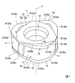
図1ないし図8は、本発明の切削インサートの一実施形態を示すものであり、図9は、この実施形態の切削インサートが着脱可能に取り付けられる刃先交換式切削工具の工具本体を示すものであり、図10は、この工具本体に上記実施形態の切削インサートが着脱可能に取り付けられた本発明の刃先交換式切削工具の一実施形態を示すものである。本実施形態の切削インサートは、超硬合金等の硬質材料により形成された多角形板状のインサート本体11を備え、このインサート本体11は、2つの多角形面12がそれぞれ3つの角部を有する三角形板状であって、これら2つの多角形面12の中心を通るインサート中心線Lに関して回転対称形状であるとともに、2つの多角形面12に関して表裏反転対称形状である。
1 to 8 show an embodiment of the cutting insert of the present invention, and FIG. 9 shows a tool body of a cutting tool with a replaceable cutting edge to which the cutting insert of this embodiment can be detachably attached. FIG. 10 shows an embodiment of the cutting tool with a replaceable cutting edge of the present invention in which the cutting insert of the above embodiment is detachably attached to the tool body. The cutting insert of the present embodiment includes a polygonal plate-shaped
これら2つの多角形面12は、図10に示すように刃先交換式切削工具の工具本体21に取り付けられたときに、一方の多角形面12がすくい面とされるとともに、他方の多角形面12は工具本体21に形成されたインサート取付座22への着座面とされる。これら2つの多角形面12の周りに配されるインサート本体11の側面13には、2つの多角形面12のすくい面と交差する逃げ面14が形成され、これらのすくい面(多角形面12)と逃げ面14との交差稜線部に切刃15が形成される。なお、2つの多角形面12の中央部には、インサート本体11をインサート取付座22に取り付けるためのインサート中心線Lを中心とした断面円形の取付孔16が、インサート本体11を上記インサート中心線L方向に貫通して開口している。
When these two
切刃15は、インサート中心線L方向から見て、多角形面12の3つの角部に配置される円弧等の凸曲線状をなすコーナ刃15aと、このコーナ刃15aの一端(図2においてインサート中心線Lを中心として時計回り方向側の端部)からコーナ刃15aに接して延びる直線状またはコーナ刃15aがなす凸曲線よりも曲率半径が大きい凸曲線状の主切刃15bと、この主切刃15bの一端において主切刃15bと鈍角に交差する方向に延びる直線状または主切刃15bがなす凸曲線よりも曲率半径が大きい凸曲線状のワイパー刃15cを備えている。また、切刃15はさらに、コーナ刃15aの他端からコーナ刃15aに接して延びるインサート中心線L方向から見て直線状の副切刃15dを備えており、この副切刃15dは1つの切刃15の他端側(図2において反時計回り方向側)に隣接する他の切刃15のワイパー刃15cと鈍角に交差する方向に延びている。
The
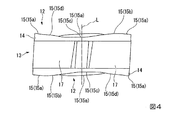
逃げ面14は、インサート本体11の側面13のうち、2つの多角形面12側の縁部に形成されており、これらの逃げ面14の間には、インサート中心線Lに沿った断面においてインサート中心線L方向に延びる複数のインサート拘束面17が、インサート中心線L方向から見て互いに交差する方向に形成されている。これらのインサート拘束面17は、本実施形態ではインサート中心線Lに平行な平面状であって、主切刃15bと副切刃15dのインサート中心線L方向の内側に形成されており、隣接するインサート拘束面17の間においてコーナ刃15aのインサート中心線L方向内側に位置する部分は凸曲面で繋げられている。
The
また、すくい面とされる上記多角形面12には、上記取付孔16の開口部の周りにインサート中心線Lに垂直な平面部12aが形成されるとともに、コーナ刃15a側には、この平面部12aから切刃15側に向かうに従いインサート中心線L方向に突出するように傾斜する傾斜部12bが形成されている。本実施形態では、切刃15のうち、コーナ刃15aおよび主切刃15bの全長と、ワイパー刃15cの主切刃15bと交差する側の一部と、副切刃15dのコーナ刃15aに接する側の一部とが傾斜部12bと逃げ面14との交差稜線部に形成され、ワイパー刃15cと副切刃15dの残りの部分は平面部12aと逃げ面14との交差稜線部に形成されている。なお、切刃15のインサート中心線L方向に最も突出した位置と上記平面部12aとの間のインサート中心線L方向における高さの差は、たとえば0.6mmとされている。
Further, a
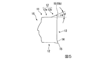
そして、上記切刃15は、コーナ刃15aとは反対側の主切刃15bの端部15eからコーナ刃15a側に向かうに従いインサート中心線Lに沿った断面における上記平面部12aに対するすくい角θが漸次増大する第1領域15Aと、この第1領域15Aからコーナ刃15a側に向かうに従い上記すくい角θが漸次減少する第2領域15Bと、この第2領域15Bからコーナ刃15aと副切刃15dとの少なくとも一部を含む部分で副切刃15d側に向かうに従い上記すくい角θが第1領域15Aよりも小さな範囲で漸次増大する第3領域15Cとを有している。さらに、この第3領域15Cにおける上記すくい角θは15°〜18°の範囲とされている。なお、本明細書においては、上述のように切削インサート単体での平面部12aを基準とした傾斜部12bのすくい面の傾斜角度のことを、便宜上すくい角θとする。
Then, the
また、切刃15はさらに、上記第3領域15Cからコーナ刃15aとは反対側の副切刃15dの端部15fに向かうに従い、上記第1領域15Aから第3領域15Cよりも大きな変化率で上記すくい角θが漸次減少する第4領域15Dを有している。なお、切刃15のうち上記平面部12aと逃げ面14との交差稜線部に形成される部分の上記すくい角θは0°である。
Further, the
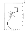
ここで、図11に符号Aで示すのは、三角形板状のインサート本体11を有する本実施形態の切削インサートにおいて、インサート中心線Lに沿ってコーナ刃15aとは反対側の主切刃15bの端部15eを通る断面を基準の0°位置とし、この基準の断面から図2においてインサート中心線Lを中心として反時計回り方向に120°の位置にある上記他の切刃15のコーナ刃15aとは反対側の主切刃15bの端部15eまでのインサート中心線Lに沿った断面におけるすくい角θを5°ずつ計算して表したものであり、これによると、本実施形態では断面位置の角度が0°〜25°の角度範囲が上記第1領域15Aとなる。
Here, reference numeral A in FIG. 11 indicates that in the cutting insert of the present embodiment having the triangular plate-shaped insert
また、この第1領域15Aからコーナ刃15a側の上記断面位置の角度が25°〜60°の角度範囲が本実施形態における第2領域15Bとなり、従って上記すくい角θは、この第2領域15Bと第1領域15Aとの境界である断面位置が25°付近で図5に示すように最大値となる。本実施形態では、この上記すくい角θの最大値は、23.526°である。さらに、本実施形態では、主切刃15bは、断面位置の角度が0°〜60°の角度範囲に形成されていて、全体がこれら第1、第2領域15A、15Bに形成されている。ここで、第2領域15Bにおける上記すくい角θは15°〜25°の範囲であることが望ましく、図6に示す断面位置の角度が45°の位置の上記すくい角θは20.456°である。
Further, the angle range in which the angle of the cross-sectional position on the
さらにまた、本実施形態では、第3領域15Cは上記断面位置の角度が60°〜75°の角度範囲とされるとともに、コーナ刃15aは断面位置の角度が60°〜70°の角度範囲に形成されており、従って上記コーナ刃15aの一端は第2領域15Bと第3領域15Cとの境界に位置していて、図7に示すこの境界における上記すくい角θは例えば16.572°である。すなわち、コーナ刃15aはその全体が第3領域に形成されるとともに、副切刃15dのコーナ刃15a側の一部も第3領域15Cに形成されている。
Furthermore, in the present embodiment, the third region 15C has the angle of the cross-sectional position in the angle range of 60 ° to 75 °, and the
さらに、本実施形態では、上記断面位置の角度が75°〜95°の角度範囲は第4領域15Dとされている。従って、断面位置の角度が75°の位置が第3領域15Cと第4領域15Dとの境界となり、図8に示すこの境界の位置における上記すくい角θは17.147°とされ、15°〜18°の範囲内とされている。
Further, in the present embodiment, the angle range in which the angle of the cross-sectional position is 75 ° to 95 ° is defined as the
また、図11に示すようにこの第4領域15Dにおいては、第1〜第3領域15A〜15Cよりも大きな変化率で上記すくい角θが漸次減少している。ここで、[すくい角θの変化量(°)]/[断面位置の角度変化量(°)]を上記すくい角θの角度変化率とすると、第1領域15Aの角度変化率は30%〜45%の範囲であって、本実施形態では40%であり、第2領域15Bの角度変化率は−15%〜−25%の範囲であって、本実施形態では−20%であり、第3領域15Cの角度変化率は0.3%〜8%の範囲であって、本実施形態では5%であるのに対し、第4領域15Dにおける角度変化率は−97%〜−77%の範囲であり、本実施形態では−87%とされている。
Further, as shown in FIG. 11, in the
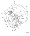
このような本実施形態の切削インサートは、図9に示すような刃先交換式切削工具の工具本体21の先端部外周に形成された上記インサート取付座22に着脱可能に取り付けられ、図10に示すような本発明の一実施形態の刃先交換式切削工具を構成する。この工具本体21は軸線Oを中心とした概略円筒状をなしており、切削加工時にはその後端部が工作機械の主軸に把持されて軸線O回りに工具回転方向Tに回転され、上記切削インサートによって被削材に切削加工を施す。
Such a cutting insert of the present embodiment is detachably attached to the
工具本体21の先端部外周には複数(本実施形態では5つ)のチップポケット23が形成されていて、インサート取付座22は、これらのチップポケット23の工具回転方向Tを向く壁面の先端部外周に形成されており、工具回転方向T側を向く平面状の底面22aと、この底面22aから工具回転方向T側に間隔をあけて配置されてインサート本体11の上記インサート拘束面17に当接可能な複数の平面状の壁面22bとを備えている。底面22aには、上記取付孔16に挿通されたクランプネジ24がねじ込まれるネジ孔22cが形成されている。
A plurality of (five in this embodiment) tip pockets 23 are formed on the outer periphery of the tip portion of the
このようなインサート取付座22に、本実施形態の切削インサートは、インサート本体11の一方の多角形面12をすくい面として工具回転方向T側に向けるとともに、他方の多角形面12の平面部12aをインサート取付座22の底面22aに密着させて着座させられる。さらに、切削インサートは、この一方の多角形面12の1つの角部に位置するコーナ刃15aを工具本体21の外周側に突出させるとともに、このコーナ刃15aの一端から延びる主切刃15bを工具本体21の先端側に向け、この主切刃15bの工具本体21外周側に突出させられたコーナ刃15aとは反対側の端部15eを工具本体21の最先端に突出させて、取付孔16に挿通したクランプネジ24をネジ孔22cにねじ込むことにより固定される。
In such an
なお、この工具本体21の最先端に突出させられた端部15eから延びるワイパー刃15cは、軸線Oに垂直な平面に対してすかし角が2°以下となるように配置され、すなわち、このワイパー刃15cは軸線Oに垂直な平面に沿って配置されるか、またはこの平面に対して2°以下の角度で工具本体21の内周側に向かうに従い後端側に向かうように傾斜して配置される。このとき、切削に使用されない切刃15に連なる側面13のインサート拘束面17はインサート取付座22の壁面22bに当接させられて、インサート中心線L回りのインサート本体11の回転が拘束される。
The
このように切削インサートが取り付けられた刃先交換式切削工具は、軸線O回りに回転されつつ該軸線Oに垂直な方向に送り出されて、高切り込み加工の場合には工具本体21最先端に突出した主切刃15bの端部15eから外周側に突出したコーナ刃15aと、このコーナ刃15aの他端に連なる副切刃15dのコーナ刃15a側の部分によって被削材を切削するとともに、端部15eに連なるワイパー刃15cによって加工面の底面を仕上げ加工する。
The blade tip exchange type cutting tool to which the cutting insert is attached in this way is sent out in the direction perpendicular to the axis O while being rotated around the axis O, and protrudes to the tip of the
主切刃15bは直線状またはコーナ刃15aよりも曲率半径の大きな凸曲線状をなしているので、その工具本体21の内周側部分によって生成される切屑の厚さは比較的薄くなる。これに対して、上記構成の切削インサートでは、この部分はインサート中心線Lに沿った断面におけるすくい角θが漸次増大する第1領域15Aとされており、このような厚さの薄い切屑に対する切刃強度は確保しながら、主切刃15bに鋭い切れ味を与えることができて、幅広に生成される切屑全体を工具本体21の内周側(軸線側)に案内するように流出方向を制御することができ、切屑排出性の向上を図ることができる。
Since the
このような主切刃15bの工具本体21内周側の部分から工具本体21外周側のコーナ刃15aに向かうに従って切屑の厚さは徐々に厚くなり、切刃15に作用する切削負荷や応力は漸次大きくなってゆく。これに対して、上記構成の切削インサートでは、この部分はコーナ刃15a側に向かうに従い上記すくい角θが正角側でも漸次減少する第2領域15Bとされており、こうして厚さが厚くなる切屑による切削負荷や応力に対して切刃強度を確保して欠損等が発生するのを防止することができる。
The thickness of the chips gradually increases from the portion of the
そして、さらにこの第2領域15Bからコーナ刃15aと副切刃15dとの少なくとも一部を含む部分(本実施形態では、コーナ刃15aの全体と副切刃15dのコーナ刃15a側の部分)は、副切刃15d側に向かうに従い上記すくい角θが第1領域15Aよりも小さな範囲で漸次増大する第3領域15Cとされている。このため、工具本体21の最外周に位置するこの第3領域15Cでは、第2領域15Bにおいて減少した上記すくい角θにより切刃強度は維持しながら、切屑を小さなカール径で工具本体21の内周側に巻き込ませることができ、第1領域15Aによって切屑排出性が向上するのと相俟って切屑の噛み込みを防ぐことができ、良好な加工面品位を得ることができる。
Further, the portion including at least a part of the
さらに、この第3領域15Cにおける切刃15の上記すくい角θは15°〜18°の範囲とされているので、確実に切刃強度を確保しつつ切屑の噛み込みを防止することができる。すなわち、後述する実施例で実証するように、第3領域15Cにおける上記すくい角θが15°を下回ったり18°を上回ったりすると、切屑を小さなカール径でカールさせることが困難となって噛み込みを生じてしまうおそれがある。また、上記すくい角θが18°を上回ると刃物角が小さくなって切刃強度が損なわれ、容易に欠損を生じるおそれもある。
Further, since the rake angle θ of the
また、本実施形態では、切刃15が、上記第3領域15Cからコーナ刃15aとは反対側の副切刃15dの端部15fに向かうに従い、第1〜第3領域15A〜15Cよりも大きな変化率(角度変化率)で上記すくい角θが漸次減少する第4領域15Dを有している。このような第4領域15Dは、工具本体21を軸線Oに対して斜め先端側に送り出して切削を行う傾斜切削加工において専ら使用されるが、この第4領域15Dにおいて生成される切屑の厚さは依然厚いままであるのに対し、第3領域15Cにおいて増加した上記すくい角θを第4領域15Dにおいて第1領域15A〜第3領域15Cよりも大きな角度変化率で減少させることにより、切刃強度を再び確保して欠損等の発生を防止することが可能となる。
Further, in the present embodiment, the
ここで、第2領域15Bにおける上記すくい角θは、上述のように15°〜25°の範囲であることが望ましい。この第2領域15Bにおける上記すくい角θが15°を下回ると、第3領域15Cにおける上記すくい角θを15°〜18°の範囲とすることができなくなって切屑処理性が損なわれるそれがある一方、第2領域15Bにおける上記すくい角θが25°を上回ると、第2、第3領域15B、15Cにおける切刃15の刃物角が小さくなりすぎて欠損等を招くおそれがある。
Here, it is desirable that the rake angle θ in the
なお、インサート本体11が上記2つの多角形面12にそれぞれ3つの角部を有する三角形板状である本実施形態の切削インサートでは、上記第1領域15Aと第2領域15Bとの境界において上記すくい角θが最大となる位置は、インサート中心線Lに沿って多角形面12に対向する方向から見て、コーナ刃15aとは反対側の主切刃15bの端部15eとインサート中心線Lとを通る直線からインサート中心線Lを中心にコーナ刃15a側に向けて15°〜45°の角度範囲内にあるのが望ましく、本実施形態では上述のように断面位置が25°付近となる。
In the cutting insert of the present embodiment in which the
この上記すくい角θが最大となる位置が15°未満の上記角度範囲にあると、第1領域15Aが小さくなって切屑を十分に工具本体の内周側に案内するように流出方向を制御することが困難となるおそれがある。その一方で、上記すくい角θが最大となる位置が45°を上回る上記角度範囲にあると、切屑が厚く生成される部分で切刃15の刃物角が小さくなり、切刃15の欠損等を確実に防止することができなくなるおそれが生じる。なお、この上記すくい角θが最大となる上記角度範囲は、17°〜40°の範囲であることが望ましく、19°〜35°の範囲であることがより望ましい。
When the position where the rake angle θ is maximized is in the angle range of less than 15 °, the
また、本実施形態の切削インサートでは、インサート本体11の側面13において2つの多角形面12側の逃げ面14の間に、インサート中心線Lに沿った断面においてこのインサート中心線L方向に延びる複数のインサート拘束面17が、インサート中心線L方向から見て互いに交差する方向に形成されている。従って、上述のようにこれらのインサート拘束面17をインサート取付座22の壁面22bに当接させることにより、インサート本体11のインサート中心線L回りの回転を拘束することができ、一層安定した切削加工を行うことが可能となる。
Further, in the cutting insert of the present embodiment, a plurality of cutting inserts extending in the insert center line L direction in a cross section along the insert center line L between the
次に、実施例を挙げて、本発明の特に第3領域15Cにおける上記すくい角θの効果について実証する。本実施例では、図11に符号Aで示したように第3領域15Cにおける上記すくい角θが15°〜18°の範囲である切削インサートを用いて、主軸回転速度808.0rpm、1刃当たりの送り量0.7mm、半径方向切り込み深さ45.0mm、軸方向切り込み深さ3.0mmの切削条件でS50Cよりなる被削材に高切り込み加工を行った場合を解析した。また、この実施例に対する比較例1として、上記図11に符号Bで示す第3領域15Cにおける上記すくい角θが15°を下回るものと、比較例2として上記図11に符号Cで示す第3領域15Cにおける上記すくい角θが18°を上回るもので、実施例と同様の切削条件により高切り込み加工を行った場合も解析した。 Next, an example will be given to demonstrate the effect of the rake angle θ in the third region 15C of the present invention. In this embodiment, as shown by reference numeral A in FIG. 11, a cutting insert in which the rake angle θ in the third region 15C is in the range of 15 ° to 18 ° is used, and the spindle rotation speed is 808.0 rpm per blade. A case was analyzed in which a work material made of S50C was subjected to high cutting under the cutting conditions of a feed amount of 0.7 mm, a cutting depth of 45.0 mm in the radial direction, and a cutting depth of 3.0 mm in the axial direction. Further, as Comparative Example 1 with respect to this Example, the rake angle θ in the third region 15C shown by reference numeral B in FIG. 11 is less than 15 °, and as Comparative Example 2, the third region shown by reference numeral C in FIG. 11 It was also analyzed when the rake angle θ in the region 15C exceeded 18 ° and high cutting was performed under the same cutting conditions as in the examples.
図12(a)〜(c)は、これら実施例および比較例1、2による切屑の流出状態を示すものであり、図12(a)は実施例、図12(b)は比較例1、図12(c)は比較例2の結果を示すものである。これら図12(a)〜(c)により、実施例では切屑が小さなカール径でカールしているのに対し、比較例1、2では切屑がカールせずに延び気味となり、噛み込みを生じるおそれがあることが分かる。 12 (a) to 12 (c) show the outflow state of chips according to these Examples and Comparative Examples 1 and 2. FIG. 12 (a) shows Examples and FIG. 12 (b) shows Comparative Examples 1 and 2. FIG. 12 (c) shows the result of Comparative Example 2. According to FIGS. 12 (a) to 12 (c), in the examples, the chips are curled with a small curl diameter, whereas in the comparative examples 1 and 2, the chips tend to extend without curling, which may cause biting. It turns out that there is.
また、図13(a)〜(c)は、実施例と比較例1、2の応力集中を解析したものであり、図13(a)は実施例、図12(b)は比較例1、図12(c)は比較例2の結果を示すものであって、切刃側の色の濃い部分が高い応力が作用している部分である。これら図12(a)〜(c)の結果により、実施例および比較例1、2ともに切削に使用される切刃15には応力が集中していることが分かるが、特に上記すくい角θが18°を上回る比較例2では高い応力が作用しており、刃物角が小さくなっていることにより切刃に欠損を生じるおそれがあることが分かる。
13 (a) to 13 (c) are analysis of the stress concentration of Examples and Comparative Examples 1 and 2, FIG. 13 (a) shows Examples, and FIG. 12 (b) shows Comparative Examples 1 and 2. FIG. 12C shows the result of Comparative Example 2, and the dark-colored portion on the cutting edge side is the portion on which high stress is applied. From the results of FIGS. 12A to 12C, it can be seen that stress is concentrated on the
なお、以下に、切削インサートのすくい面の傾斜角度(本明細書における上述したすくい角θ)の測定方法の一例を述べる。まず、第1のステップとして、非接触三次元測定器を用いてインサート本体1の三次元形状の測定を行い、これらの測定結果を電子データとして保存する。次に、第2ステップとして、この三次元測定データと形状測定ソフトを用いて、インサート本体1の切刃15の稜線部分において、インサート中心線Lからの所定の放射角度の間隔幅毎に、インサート中心線Lに沿った複数の断面図を作成する。最後に、第3のステップとして、図5から図8に示すようなインサート本体1の切刃15の稜線部分の断面図を得ることによって、インサート本体の平面部12aを基準面として、すくい面となる傾斜部12bのすくい面の傾斜角度、すなわち上記すくい角θを求めることができる。
An example of a method for measuring the inclination angle of the rake face of the cutting insert (the rake angle θ described above in the present specification) will be described below. First, as a first step, the three-dimensional shape of the insert body 1 is measured using a non-contact three-dimensional measuring device, and these measurement results are stored as electronic data. Next, as a second step, using the three-dimensional measurement data and the shape measurement software, the insert is inserted at the ridgeline portion of the
11 インサート本体
12 多角形面
12a 平面部
12b 傾斜部
13 側面
14 逃げ面
15 切刃
15a コーナ刃
15b 主切刃
15c ワイパー刃
15d 副切刃
15A 第1領域
15B 第2領域
15C 第3領域
15D 第4領域
16 取付孔
17 インサート拘束面
21 工具本体
22 インサート取付座
23 チップポケット
24 クランプネジ
L インサート中心線
θ インサート中心線に沿った断面における切刃15のすくい角
O 工具本体21の軸線
T 工具回転方向
11
Claims (5)
上記インサート本体は、上記2つの多角形面の中心を通るインサート中心線に関して回転対称形状であるとともに、これら2つの多角形面に関して表裏反転対称形状であり、
上記切刃は、上記多角形面の角部に位置するコーナ刃と、このコーナ刃の一端から延びる主切刃と、上記コーナ刃の他端から延びる副切刃とを備えるとともに、
上記コーナ刃とは反対側の上記主切刃の端部から該コーナ刃側に向かうに従い上記インサート中心線に沿った断面におけるすくい角が漸次増大する第1領域と、この第1領域から上記コーナ刃側に向かうに従い上記すくい角が漸次減少する第2領域と、この第2領域から上記コーナ刃と上記副切刃との少なくとも一部を含む部分で該副切刃側に向かうに従い上記すくい角が漸次増大する第3領域とを有し、
上記第3領域は上記第1領域よりも領域の大きさが小さく、
上記第3領域における上記すくい角が15°〜18°の範囲であることを特徴とする切削インサート。 Two polygonal surfaces that form a polygon and one of which is a rake face and the other is a seating surface, and are arranged around these two polygonal surfaces and intersect with the rake surface of the polygonal surface. A cutting insert having a polygonal plate-shaped insert body having a side surface on which a flank surface is formed and a cutting edge formed at a crossing ridge between the rake face and the flank surface.
The insert body has a rotationally symmetric shape with respect to the insert center line passing through the centers of the two polygonal planes, and has a front-back inverted symmetric shape with respect to these two polygonal planes.
The cutting blade includes a corner blade located at a corner of the polygonal surface, a main cutting blade extending from one end of the corner blade, and a secondary cutting blade extending from the other end of the corner blade.
A first region in which the rake angle in the cross section along the insert center line gradually increases from the end of the main cutting blade on the side opposite to the corner blade toward the corner blade side, and the corner from this first region. A second region in which the rake angle gradually decreases toward the blade side, and a portion including at least a part of the corner blade and the sub-cutting blade from this second region, and the rake angle toward the sub-cutting blade side. and a third region GaSusumu increased following,
The size of the third region is smaller than that of the first region.
The cutting insert, characterized in that said rake angle in the third region is in the range of 15 ° ~ 18 °.
上記第1領域と第2領域との境界において上記すくい角が最大となる位置は、上記インサート中心線に沿って上記多角形面に対向する方向から見て、上記コーナ刃とは反対側の上記主切刃の端部と上記インサート中心線とを通る直線から上記インサート中心線を中心に上記コーナ刃側に向けて15°〜45°の角度範囲内であることを特徴とする請求項1から請求項3のうちいずれか一項に記載の切削インサート。 The insert body has a triangular plate shape in which the two polygonal surfaces each have three corners.
The position where the rake angle is maximized at the boundary between the first region and the second region is the position opposite to the corner blade when viewed from the direction facing the polygonal surface along the insert center line. From claim 1, the straight line passing through the end of the main cutting edge and the insert center line is within an angle range of 15 ° to 45 ° from the straight line passing through the insert center line toward the corner blade side with the insert center line as the center. The cutting insert according to any one of claims 3.
上記2つの多角形面のうちの一方の多角形面をすくい面として工具回転方向に向け、
この一方の多角形面の1つの上記コーナ刃を上記工具本体の外周側に向けるとともに、
この1つの上記コーナ刃の一端から延びる1つの上記主切刃を上記工具本体の先端側に向け、この1つの上記主切刃の上記コーナ刃とは反対側の端部を上記工具本体の最先端に突出させて着脱可能に取り付けられていることを特徴とする刃先交換式切削工具。 The cutting insert according to any one of claims 1 to 4 is attached to an insert mounting seat formed on the outer periphery of the tip of a tool body that is rotated around an axis.
One of the above two polygonal surfaces is used as a rake face and oriented in the tool rotation direction.
One of the corner blades on one of the polygonal surfaces is directed toward the outer peripheral side of the tool body, and
One of the main cutting blades extending from one end of the one corner blade is directed toward the tip end side of the tool body, and the end of the one main cutting blade opposite to the corner blade is the most of the tool body. A cutting tool with a replaceable cutting edge that is attached to the tip so that it can be attached and detached.
Priority Applications (1)
| Application Number | Priority Date | Filing Date | Title |
|---|---|---|---|
| JP2018001398A JP6965754B2 (en) | 2018-01-09 | 2018-01-09 | Cutting inserts and cutting tools with replaceable cutting edges |
Applications Claiming Priority (1)
| Application Number | Priority Date | Filing Date | Title |
|---|---|---|---|
| JP2018001398A JP6965754B2 (en) | 2018-01-09 | 2018-01-09 | Cutting inserts and cutting tools with replaceable cutting edges |
Publications (2)
| Publication Number | Publication Date |
|---|---|
| JP2019119022A JP2019119022A (en) | 2019-07-22 |
| JP6965754B2 true JP6965754B2 (en) | 2021-11-10 |
Family
ID=67307063
Family Applications (1)
| Application Number | Title | Priority Date | Filing Date |
|---|---|---|---|
| JP2018001398A Active JP6965754B2 (en) | 2018-01-09 | 2018-01-09 | Cutting inserts and cutting tools with replaceable cutting edges |
Country Status (1)
| Country | Link |
|---|---|
| JP (1) | JP6965754B2 (en) |
Families Citing this family (1)
| Publication number | Priority date | Publication date | Assignee | Title |
|---|---|---|---|---|
| JP7344168B2 (en) * | 2020-03-25 | 2023-09-13 | 京セラ株式会社 | Manufacturing method for cutting inserts, cutting tools, and cut products |
Family Cites Families (4)
| Publication number | Priority date | Publication date | Assignee | Title |
|---|---|---|---|---|
| JP3196566B2 (en) * | 1995-05-10 | 2001-08-06 | 三菱マテリアル株式会社 | Indexable inserts and indexable cutters |
| DE102006044605A1 (en) * | 2006-09-19 | 2008-03-27 | Komet Group Holding Gmbh | Indexable insert and use of the indexable insert in a solid drill |
| JP5243396B2 (en) * | 2009-12-10 | 2013-07-24 | 住友電工ハードメタル株式会社 | Interchangeable cutting edge insert and milling cutter |
| JP2016144831A (en) * | 2013-06-05 | 2016-08-12 | 株式会社タンガロイ | Cutting insert |
-
2018
- 2018-01-09 JP JP2018001398A patent/JP6965754B2/en active Active
Also Published As
| Publication number | Publication date |
|---|---|
| JP2019119022A (en) | 2019-07-22 |
Similar Documents
| Publication | Publication Date | Title |
|---|---|---|
| JP6127439B2 (en) | Replaceable cutting tool and cutting insert | |
| JP6531883B1 (en) | Cutting insert and indexable cutting tool | |
| EP2444188B1 (en) | Cutting insert and face milling cutter | |
| US8845241B2 (en) | Radius end mill and cutting insert | |
| WO2017122715A1 (en) | Cutting insert and blade-tip-replaceable cutting tool | |
| WO2015115379A1 (en) | Insert and cutting edge-replaceable rotary cutting tool | |
| JP5227342B2 (en) | Cutting insert, cutting tool, and cutting method | |
| JP6855024B1 (en) | Cutting inserts and cutting tools equipped with them | |
| JP2008229745A (en) | Cutting insert and insert removable type rotary cutting tool | |
| KR20160101158A (en) | Drill insert and indexable drill | |
| EP3167991A1 (en) | Cutting insert and face milling cutter | |
| JP4876977B2 (en) | Cutting insert and insert detachable rolling tool | |
| JP5783025B2 (en) | Cutting insert and cutting edge exchangeable end mill | |
| JP4983352B2 (en) | Cutting insert and insert detachable rolling tool | |
| KR102407067B1 (en) | Cutting inserts and indexable cutting tools | |
| JP7119781B2 (en) | Cutting inserts and indexable cutting tools | |
| JP4983351B2 (en) | Cutting insert and insert detachable rolling tool | |
| JP4821244B2 (en) | Throw-away tip and throw-away end mill | |
| JP6965754B2 (en) | Cutting inserts and cutting tools with replaceable cutting edges | |
| JP2008279519A (en) | Throwaway type cutting tool and cutting edge tip equipped with the same | |
| JP5849817B2 (en) | Square end mill | |
| JP5126205B2 (en) | Ball end mill | |
| JP7242997B2 (en) | End mill body of indexable end mill | |
| JPH11156625A (en) | Throw away tip, and throw away type ball end mill mounting it | |
| JP6014427B2 (en) | Cutting insert and cutting tool using the same |
Legal Events
| Date | Code | Title | Description |
|---|---|---|---|
| A621 | Written request for application examination |
Free format text: JAPANESE INTERMEDIATE CODE: A621 Effective date: 20201120 |
|
| A977 | Report on retrieval |
Free format text: JAPANESE INTERMEDIATE CODE: A971007 Effective date: 20210415 |
|
| A131 | Notification of reasons for refusal |
Free format text: JAPANESE INTERMEDIATE CODE: A131 Effective date: 20210427 |
|
| A521 | Written amendment |
Free format text: JAPANESE INTERMEDIATE CODE: A523 Effective date: 20210623 |
|
| TRDD | Decision of grant or rejection written | ||
| A01 | Written decision to grant a patent or to grant a registration (utility model) |
Free format text: JAPANESE INTERMEDIATE CODE: A01 Effective date: 20210921 |
|
| A61 | First payment of annual fees (during grant procedure) |
Free format text: JAPANESE INTERMEDIATE CODE: A61 Effective date: 20211004 |
|
| R150 | Certificate of patent or registration of utility model |
Ref document number: 6965754 Country of ref document: JP Free format text: JAPANESE INTERMEDIATE CODE: R150 |