JP6965731B2 - Power storage module and manufacturing method of power storage module - Google Patents
Power storage module and manufacturing method of power storage module Download PDFInfo
- Publication number
- JP6965731B2 JP6965731B2 JP2017247841A JP2017247841A JP6965731B2 JP 6965731 B2 JP6965731 B2 JP 6965731B2 JP 2017247841 A JP2017247841 A JP 2017247841A JP 2017247841 A JP2017247841 A JP 2017247841A JP 6965731 B2 JP6965731 B2 JP 6965731B2
- Authority
- JP
- Japan
- Prior art keywords
- side portion
- rib
- outer edge
- stacking direction
- resin
- Prior art date
- Legal status (The legal status is an assumption and is not a legal conclusion. Google has not performed a legal analysis and makes no representation as to the accuracy of the status listed.)
- Active
Links
Images


Classifications
-
- Y—GENERAL TAGGING OF NEW TECHNOLOGICAL DEVELOPMENTS; GENERAL TAGGING OF CROSS-SECTIONAL TECHNOLOGIES SPANNING OVER SEVERAL SECTIONS OF THE IPC; TECHNICAL SUBJECTS COVERED BY FORMER USPC CROSS-REFERENCE ART COLLECTIONS [XRACs] AND DIGESTS
- Y02—TECHNOLOGIES OR APPLICATIONS FOR MITIGATION OR ADAPTATION AGAINST CLIMATE CHANGE
- Y02E—REDUCTION OF GREENHOUSE GAS [GHG] EMISSIONS, RELATED TO ENERGY GENERATION, TRANSMISSION OR DISTRIBUTION
- Y02E60/00—Enabling technologies; Technologies with a potential or indirect contribution to GHG emissions mitigation
- Y02E60/10—Energy storage using batteries
-
- Y—GENERAL TAGGING OF NEW TECHNOLOGICAL DEVELOPMENTS; GENERAL TAGGING OF CROSS-SECTIONAL TECHNOLOGIES SPANNING OVER SEVERAL SECTIONS OF THE IPC; TECHNICAL SUBJECTS COVERED BY FORMER USPC CROSS-REFERENCE ART COLLECTIONS [XRACs] AND DIGESTS
- Y02—TECHNOLOGIES OR APPLICATIONS FOR MITIGATION OR ADAPTATION AGAINST CLIMATE CHANGE
- Y02P—CLIMATE CHANGE MITIGATION TECHNOLOGIES IN THE PRODUCTION OR PROCESSING OF GOODS
- Y02P70/00—Climate change mitigation technologies in the production process for final industrial or consumer products
- Y02P70/50—Manufacturing or production processes characterised by the final manufactured product
Description
本発明の一側面は、蓄電モジュール及び蓄電モジュールの製造方法に関する。 One aspect of the present invention relates to a power storage module and a method for manufacturing the power storage module.
従来の蓄電モジュールとして、電極板の一方面に正極が形成され、他方面に負極が形成されたバイポーラ電極を備えた、いわゆるバイポーラ型の蓄電モジュールが知られている(特許文献1参照)。かかる蓄電モジュールは、複数のバイポーラ電極を積層してなる電極積層体を備えている。電極積層体の周囲には、積層方向で隣り合うバイポーラ電極間を封止する封止体が設けられている。封止体によってバイポーラ電極間に形成された内部空間には電解液が収容されている。 As a conventional power storage module, a so-called bipolar type power storage module having a bipolar electrode having a positive electrode formed on one surface of an electrode plate and a negative electrode formed on the other surface is known (see Patent Document 1). Such a power storage module includes an electrode laminate formed by laminating a plurality of bipolar electrodes. Around the electrode laminate, a sealant is provided to seal between the bipolar electrodes adjacent to each other in the lamination direction. The electrolytic solution is housed in the internal space formed between the bipolar electrodes by the sealant.
ところで、上述の蓄電モジュールでは、封止体を構成する樹脂材料の熱収縮によりバイポーラ電極が変形する場合がある。これによって、例えば、バイポーラ電極にしわが発生すると、積層方向で隣り合うバイポーラ電極間の距離が増大する結果、蓄電モジュールの抵抗が増大するおそれがある。 By the way, in the above-mentioned power storage module, the bipolar electrode may be deformed due to heat shrinkage of the resin material constituting the sealing body. As a result, for example, when the bipolar electrodes are wrinkled, the distance between the bipolar electrodes adjacent to each other in the stacking direction increases, and as a result, the resistance of the power storage module may increase.
本発明の一側面は、上記課題の解決のためになされたものであり、バイポーラ電極の変形を抑制することができる蓄電モジュール及び蓄電モジュールの製造方法を提供する。 One aspect of the present invention has been made to solve the above problems, and provides a power storage module and a method for manufacturing a power storage module capable of suppressing deformation of a bipolar electrode.
本発明の一側面に係る蓄電モジュールは、電極板、電極板の一方面に設けられた正極、及び電極板の他方面に設けられた負極を含むバイポーラ電極が積層されてなる電極積層体と、電極積層体の積層方向において隣り合うバイポーラ電極間を封止する封止体と、を備え、封止体は、バイポーラ電極の外縁部に設けられた第1樹脂部と、第1樹脂部の周囲に設けられた第2樹脂部と、第2樹脂部を構成する樹脂材料と同じ樹脂材料によって構成されたリブと、を有し、外縁部は矩形枠状であり、第2樹脂部は、外縁部に沿って延在する第1側部、第2側部、第3側部及び第4側部を有し、リブは、第1側部の外面に設けられた第1リブ部分を有し、第1リブ部分は、外縁部に沿って延在すると共に、積層方向に分布している。 The power storage module according to one aspect of the present invention includes an electrode laminate, an electrode laminate in which a bipolar electrode including a positive electrode provided on one surface of the electrode plate and a negative electrode provided on the other surface of the electrode plate is laminated. A sealing body for sealing between adjacent bipolar electrodes in the stacking direction of the electrode laminated body is provided, and the sealing body includes a first resin portion provided on the outer edge portion of the bipolar electrode and a periphery of the first resin portion. It has a second resin portion provided in the above and ribs made of the same resin material as the resin material constituting the second resin portion, the outer edge portion has a rectangular frame shape, and the second resin portion has an outer edge. It has a first side portion, a second side portion, a third side portion and a fourth side portion extending along the portion, and the rib has a first rib portion provided on the outer surface of the first side portion. , The first rib portion extends along the outer edge portion and is distributed in the stacking direction.
この蓄電モジュールでは、バイポーラ電極間を封止する封止体が、第1樹脂部及び第2樹脂部に加えて、第2樹脂部を構成する樹脂材料と同じ樹脂材料によって構成されたリブを有している。リブは、第2樹脂部における第1側部の外面に設けられた第1リブ部分を有している。このため、例えば、射出成型により第1側部及び第1リブ部分を同時に形成した場合、第1リブ部分は、形状的に第1側部よりも冷却され易いので、第1側部よりも先に溶融状態から凝固状態に移行する。凝固状態の樹脂材料の強度は、溶融状態の樹脂材料の強度よりも高い。このように強度の高い第1リブ部分が、外縁部に沿って延在しているので、第1側部を構成する樹脂材料が外縁部に沿って熱収縮することが抑制される。また、第1リブ部分は積層方向に分布しているので、第1側部が積層方向に湾曲することが抑制される。この結果、バイポーラ電極の変形が抑制される。 In this power storage module, the sealant that seals between the bipolar electrodes has ribs made of the same resin material as the resin material constituting the second resin portion in addition to the first resin portion and the second resin portion. doing. The rib has a first rib portion provided on the outer surface of the first side portion of the second resin portion. Therefore, for example, when the first side portion and the first rib portion are formed at the same time by injection molding, the first rib portion is more easily cooled than the first side portion in terms of shape, so that the first rib portion is ahead of the first side portion. It shifts from the molten state to the solidified state. The strength of the resin material in the solidified state is higher than the strength of the resin material in the molten state. Since the first rib portion having high strength extends along the outer edge portion, the resin material constituting the first side portion is suppressed from heat shrinking along the outer edge portion. Further, since the first rib portions are distributed in the stacking direction, it is possible to prevent the first side portion from being curved in the stacking direction. As a result, the deformation of the bipolar electrode is suppressed.
第1リブ部分は、外縁部に沿って延在する成分と、積層方向に沿って延在する成分と、を有していてもよい。この場合、第1リブ部分は、外縁部だけでなく積層方向に沿って延在する成分も有しているので、第1側部を構成する樹脂材料が外縁部だけでなく積層方向に沿って熱収縮することも抑制される。 The first rib portion may have a component extending along the outer edge portion and a component extending along the stacking direction. In this case, since the first rib portion has a component extending not only in the outer edge portion but also in the laminating direction, the resin material constituting the first side portion is not only in the outer edge portion but also in the laminating direction. Heat shrinkage is also suppressed.
第1側部及び第2側部は、電極積層体を挟んで互いに対向し、リブは、第2側部の外面に設けられた第2リブ部分を更に有し、第2リブ部分は、外縁部に沿って延在すると共に、積層方向に分布していてもよい。第1側部及び第2側部は、電極積層体を挟んで互いに対向しているので、第1側部及び第2側部を構成する樹脂材料の熱収縮量の差が大きい場合、バイポーラ電極に歪みが生じるおそれがある。また、第1側部及び第2側部の湾曲が互いに異なる場合も、バイポーラ電極に歪みが生じるおそれがある。この蓄電モジュールでは、リブは、第2側部の外面に設けられた第2リブ部分を更に有している。このため、第2リブ部分によれば、第1リブ部分と同様に、第2側部を構成する樹脂材料が外縁部に沿って熱収縮することが抑制されると共に、第2側部が積層方向に湾曲することが抑制される。これにより、第1側部及び第2側部を構成する樹脂材料の熱収縮がいずれも抑制される。また、第1側部及び第2側部の積層方向における湾曲がいずれも抑制される。したがって、バイポーラ電極の歪みを抑制することができる。 The first side portion and the second side portion face each other with the electrode laminate interposed therebetween, the rib further has a second rib portion provided on the outer surface of the second side portion, and the second rib portion has an outer edge. It may extend along the portion and may be distributed in the stacking direction. Since the first side portion and the second side portion face each other with the electrode laminate interposed therebetween, when the difference in the amount of heat shrinkage of the resin materials constituting the first side portion and the second side portion is large, the bipolar electrode May be distorted. Further, when the curvatures of the first side portion and the second side portion are different from each other, the bipolar electrode may be distorted. In this power storage module, the rib further has a second rib portion provided on the outer surface of the second side portion. Therefore, according to the second rib portion, similarly to the first rib portion, the resin material constituting the second side portion is suppressed from heat shrinking along the outer edge portion, and the second side portion is laminated. Curving in the direction is suppressed. As a result, the heat shrinkage of the resin material constituting the first side portion and the second side portion is suppressed. Further, the curvature of the first side portion and the second side portion in the stacking direction is suppressed. Therefore, the distortion of the bipolar electrode can be suppressed.
外縁部は長方形枠状であり、第1側部及び第2側部が外縁部に沿って延在する長さは、第3側部及び第4側部が外縁部に沿って延在する長さよりも長くてもよい。この場合、第1側部及び第2側部は、長方形枠状である外縁部の長辺部分に沿って設けられている。長辺部分は短辺部分よりも変形し易いので、第1リブ部分により効果的にバイポーラ電極の変形が抑制される。 The outer edge portion has a rectangular frame shape, and the length of the first side portion and the second side portion extending along the outer edge portion is the length of the third side portion and the fourth side portion extending along the outer edge portion. It may be longer than that. In this case, the first side portion and the second side portion are provided along the long side portion of the outer edge portion having a rectangular frame shape. Since the long side portion is more easily deformed than the short side portion, the deformation of the bipolar electrode is effectively suppressed by the first rib portion.
リブは、第3側部の外面に設けられた第3リブ部分を更に有し、第3リブ部分は、外縁部に沿って延在すると共に、積層方向に分布しており、第4側部には、電極積層体において隣り合うバイポーラ電極間の複数の内部空間と連通する開口が設けられていてもよい。この場合、リブは、第3側部の外面に設けられた第3リブ部分を更に有している。このため、第3リブ部分によれば、第1リブ部分と同様に、第3側部を構成する樹脂材料が外縁部に沿って熱収縮することが抑制されると共に、第3側部が積層方向に湾曲することが抑制される。第4側部には開口が設けられているので、第4側部を構成する樹脂材料の熱収縮が抑制されると共に、第4側部の積層方向における湾曲が抑制される。このように、第2樹脂部の各側部を構成する樹脂材料の熱収縮が抑制されると共に、第2樹脂部の各側部の積層方向における湾曲が抑制される。この結果、バイポーラ電極の変形が一層抑制される。 The rib further has a third rib portion provided on the outer surface of the third side portion, and the third rib portion extends along the outer edge portion and is distributed in the stacking direction, and the fourth side portion. May be provided with an opening communicating with a plurality of internal spaces between adjacent bipolar electrodes in the electrode laminate. In this case, the rib further has a third rib portion provided on the outer surface of the third side portion. Therefore, according to the third rib portion, similarly to the first rib portion, the resin material constituting the third side portion is suppressed from heat shrinking along the outer edge portion, and the third side portion is laminated. Curving in the direction is suppressed. Since the opening is provided in the fourth side portion, the heat shrinkage of the resin material constituting the fourth side portion is suppressed, and the curvature of the fourth side portion in the stacking direction is suppressed. In this way, the heat shrinkage of the resin material constituting each side portion of the second resin portion is suppressed, and the curvature of each side portion of the second resin portion in the stacking direction is suppressed. As a result, the deformation of the bipolar electrode is further suppressed.
第1リブ部分は、積層方向から見て重複部分を有していなくてもよい。この場合、第1リブ部分は、積層方向に互いに接離可能な一対の金型に対してアンダーカット形状ではない。したがって、第1リブ部分を容易に形成することができる。 The first rib portion does not have to have an overlapping portion when viewed from the stacking direction. In this case, the first rib portion does not have an undercut shape with respect to a pair of molds that can be brought into contact with each other in the stacking direction. Therefore, the first rib portion can be easily formed.
本発明の一側面に係る蓄電モジュールの製造方法は、電極板、電極板の一方面に設けられた正極、及び電極板の他方面に設けられた負極を含むバイポーラ電極が積層されてなる電極積層体と、第1樹脂部、第2樹脂部、及びリブを有し、電極積層体の積層方向において隣り合うバイポーラ電極間を封止する封止体と、を備える蓄電モジュールの製造方法であって、バイポーラ電極の外縁部に第1樹脂部を設ける工程と、第1樹脂部が設けられたバイポーラ電極を積層することにより、電極積層体を形成する工程と、矩形枠状である外縁部に沿って延在する第1側部、第2側部、第3側部、及び第4側部を有する第2樹脂部を第1樹脂部の周囲に設ける工程と、外縁部に沿って延在すると共に、積層方向に分布している第1リブ部分を有し、第2樹脂部を構成する樹脂材料と同じ樹脂材料によって構成されたリブを設ける工程と、を含み、第2樹脂部を設ける工程と、リブを設ける工程とは、一対の金型を用いた射出成型により同時に行われ、第1樹脂部の周囲に第1側部が設けられると共に、積層方向からみて重複部分を有していない第1リブ部分が第1側部の外面に設けられる。 The method for manufacturing a power storage module according to one aspect of the present invention is an electrode lamination in which a bipolar electrode including an electrode plate, a positive electrode provided on one surface of the electrode plate, and a negative electrode provided on the other surface of the electrode plate is laminated. A method for manufacturing a power storage module including a body, a first resin portion, a second resin portion, and a sealing body having ribs and sealing between adjacent bipolar electrodes in the stacking direction of the electrode laminate. , A step of providing a first resin portion on the outer edge portion of the bipolar electrode, a step of forming an electrode laminate by laminating the bipolar electrode provided with the first resin portion, and along the outer edge portion having a rectangular frame shape. A step of providing a second resin portion having a first side portion, a second side portion, a third side portion, and a fourth side portion extending around the first resin portion and extending along the outer edge portion. A step of providing a second resin portion including a step of providing a rib having a first rib portion distributed in the stacking direction and made of the same resin material as the resin material constituting the second resin portion. The step of providing the ribs is simultaneously performed by injection molding using a pair of molds, the first side portion is provided around the first resin portion, and there is no overlapping portion when viewed from the stacking direction. The first rib portion is provided on the outer surface of the first side portion.
この蓄電モジュールの製造方法は、第2樹脂部を第1樹脂部の周囲に設ける工程と、バイポーラ電極の外縁部に沿って延在すると共に、積層方向に分布している第1リブ部分を有し、第2樹脂部を構成する樹脂材料と同じ樹脂材料によって構成されたリブを設ける工程と、を含んでいる。これらの工程は、一対の金型を用いた射出成型により同時に行われ、第1樹脂部の周囲に第2樹脂部の第1側部が設けられると共に、第1リブ部分が第1側部の外面に設けられる。第1リブ部分は、形状的に第1側部よりも冷却され易いので、第1側部よりも先に溶融状態から凝固状態に移行する。凝固状態の樹脂材料の強度は、溶融状態の樹脂材料の強度よりも高い。このように強度の高い第1リブ部分が、外縁部に沿って延在しているので、第1側部を構成する樹脂材料が外縁部に沿って熱収縮することが抑制される。また、第1リブ部分は積層方向に分布しているので、第1側部が積層方向に湾曲することが抑制される。この結果、バイポーラ電極の変形が抑制される。また、第1リブ部分は、積層方向からみて重複部分を有していない。したがって、第1リブ部分は、積層方向に接離可能な一対の金型に対してアンダーカット形状にならない。このため、第1リブ部分を容易に形成することができる。 The manufacturing method of this power storage module includes a step of providing a second resin portion around the first resin portion and a first rib portion extending along the outer edge portion of the bipolar electrode and distributed in the stacking direction. However, it includes a step of providing ribs made of the same resin material as the resin material constituting the second resin portion. These steps are simultaneously performed by injection molding using a pair of molds, the first side portion of the second resin portion is provided around the first resin portion, and the first rib portion is the first side portion. It is provided on the outer surface. Since the first rib portion is shaped to be cooled more easily than the first side portion, the first rib portion shifts from the molten state to the solidified state before the first side portion. The strength of the resin material in the solidified state is higher than the strength of the resin material in the molten state. Since the first rib portion having high strength extends along the outer edge portion, the resin material constituting the first side portion is suppressed from heat shrinking along the outer edge portion. Further, since the first rib portions are distributed in the stacking direction, it is possible to prevent the first side portion from being curved in the stacking direction. As a result, the deformation of the bipolar electrode is suppressed. Further, the first rib portion does not have an overlapping portion when viewed from the stacking direction. Therefore, the first rib portion does not have an undercut shape with respect to a pair of molds that can be brought into contact with each other in the stacking direction. Therefore, the first rib portion can be easily formed.
本発明の一側面によれば、バイポーラ電極の変形を抑制することができる蓄電モジュール及び蓄電モジュールの製造方法を提供することができる。 According to one aspect of the present invention, it is possible to provide a power storage module and a method for manufacturing a power storage module capable of suppressing deformation of the bipolar electrode.
以下、添付図面を参照して、実施形態について詳細に説明する。説明において、同一要素又は同一機能を有する要素には、同一符号を用いることとし、重複する説明は省略する。 Hereinafter, embodiments will be described in detail with reference to the accompanying drawings. In the description, the same reference numerals will be used for the same elements or elements having the same function, and duplicate description will be omitted.
図1は、実施形態に係る蓄電装置を示す概略断面図である。図1に示される蓄電装置1は、例えばフォークリフト、ハイブリッド自動車、電気自動車等の各種車両のバッテリとして用いられる。蓄電装置1は、複数の蓄電モジュール4を積層してなる蓄電モジュール積層体2と、蓄電モジュール積層体2に対して積層方向に拘束荷重を付加する拘束部材3とを備えて構成されている。
FIG. 1 is a schematic cross-sectional view showing a power storage device according to an embodiment. The power storage device 1 shown in FIG. 1 is used as a battery for various vehicles such as forklifts, hybrid vehicles, and electric vehicles. The power storage device 1 includes a power
蓄電モジュール積層体2は、複数(本実施形態では3体)の蓄電モジュール4と、複数(本実施形態では4枚)の導電板5とによって構成されている。蓄電モジュール4は、例えば後述するバイポーラ電極14を備えたバイポーラ電池であり、積層方向から見て矩形状である。蓄電モジュール4は、例えばニッケル水素二次電池、リチウムイオン二次電池等の二次電池、又は電気二重層キャパシタである。以下の説明では、ニッケル水素二次電池を例示する。
The power
積層方向に隣り合う蓄電モジュール4,4同士は、導電板5を介して電気的に接続されている。導電板5は、積層方向に隣り合う蓄電モジュール4,4間と、積層端に位置する蓄電モジュール4の外側と、にそれぞれ配置されている。積層端に位置する蓄電モジュール4の外側に配置された一方の導電板5には、正極端子6が接続されている。積層端に位置する蓄電モジュール4の外側に配置された他方の導電板5には、負極端子7が接続されている。正極端子6及び負極端子7は、例えば導電板5の縁部から積層方向に交差する方向に引き出されている。正極端子6及び負極端子7により、蓄電装置1の充放電が実施される。
The
各導電板5の内部には、空気等の冷媒を流通させる複数の流路5aが設けられている。各流路5aは、例えば積層方向と、正極端子6及び負極端子7の引き出し方向とにそれぞれ直交する方向に互いに平行に延在している。これらの流路5aに冷媒を流通させることで、導電板5は、蓄電モジュール4,4同士を電気的に接続する接続部材としての機能のほか、蓄電モジュール4で発生した熱を放熱する放熱板としての機能を併せ持つ。なお、図1の例では、積層方向から見た導電板5の面積は、蓄電モジュール4の面積よりも小さいが、放熱性の向上の観点から、導電板5の面積は、蓄電モジュール4の面積と同じであってもよく、蓄電モジュール4の面積よりも大きくてもよい。
Inside each
拘束部材3は、蓄電モジュール積層体2を積層方向に挟む一対のエンドプレート8,8と、エンドプレート8,8同士を締結する締結ボルト9及びナット10とによって構成されている。エンドプレート8は、積層方向から見た蓄電モジュール4及び導電板5の面積よりも一回り大きい面積を有する矩形状の金属板である。エンドプレート8の内側面(蓄電モジュール積層体2側の面)には、電気絶縁性を有するフィルムFが設けられている。フィルムFにより、エンドプレート8と導電板5との間が絶縁されている。
The restraint member 3 is composed of a pair of end plates 8 and 8 that sandwich the power
エンドプレート8の縁部には、蓄電モジュール積層体2よりも外側となる位置に挿通孔8aが設けられている。締結ボルト9は、一方のエンドプレート8の挿通孔8aから他方のエンドプレート8の挿通孔8aに向かって通され、他方のエンドプレート8の挿通孔8aから突出した締結ボルト9の先端部分には、ナット10が螺合されている。これにより、蓄電モジュール4及び導電板5がエンドプレート8,8によって挟持されて蓄電モジュール積層体2としてユニット化されると共に、蓄電モジュール積層体2に対して積層方向に拘束荷重が付加される。
An
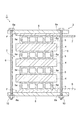
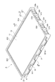
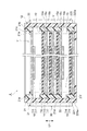
次に、蓄電モジュール4の構成について更に詳細に説明する。図2及び図3は、図1の蓄電モジュールの斜視図である。図4は、図3のIV−IV線に沿っての断面図である。図5は、図1の蓄電モジュールの側面図である。図2〜図5に示されるように、蓄電モジュール4は、電極積層体11と、封止体12とを備えている。
Next, the configuration of the
電極積層体11は、セパレータ13を介して複数のバイポーラ電極14が積層されてなる。この例では、電極積層体11の積層方向D1は蓄電モジュール積層体2の積層方向と一致している。バイポーラ電極14は、電極板15、電極板15の一方面15aに設けられた正極16、及び電極板15の他方面15bに設けられた負極17を含んでいる。正極16は、正極活物質が塗工されてなる正極活物質層である。負極17は、負極活物質が塗工されてなる負極活物質層である。電極積層体11において、一のバイポーラ電極14の正極16は、セパレータ13を挟んで積層方向D1に隣り合う一方のバイポーラ電極14の負極17と対向している。電極積層体11において、一のバイポーラ電極14の負極17は、セパレータ13を挟んで積層方向D1に隣り合う他方のバイポーラ電極14の正極16と対向している。
The
電極積層体11において、積層方向D1の一端には負極終端電極18が配置され、積層方向D1の他端には正極終端電極19が配置されている。負極終端電極18は、電極板15、及び電極板15の他方面15bに設けられた負極17を含んでいる。負極終端電極18の負極17は、セパレータ13を介して積層方向D1の一端のバイポーラ電極14の正極16と対向している。負極終端電極18の電極板15の一方面15aには、蓄電モジュール4に隣接する一方の導電板5が接触している。正極終端電極19は、電極板15、及び電極板15の一方面15aに設けられた正極16を含んでいる。正極終端電極19の電極板15の他方面15bには、蓄電モジュール4に隣接する他方の導電板5が接触している。正極終端電極19の正極16は、セパレータ13を介して積層方向D1の他端のバイポーラ電極14の負極17と対向している。
In the
電極板15は、金属製であり、例えばニッケル又はニッケルメッキ鋼板からなる。電極板15は、例えばニッケルからなる金属箔である。積層方向D1から見て、電極板15は、例えば矩形状であり、電極板15の外縁部15c(バイポーラ電極14の外縁部)は、例えば矩形枠状である。本実施形態では、積層方向D1から見て、電極板15は長方形状であり、外縁部15cは長方形枠状である。外縁部15cは、正極活物質及び負極活物質が塗工されない未塗工領域である。なお、矩形枠状とは、外縁及び内縁が矩形状である枠の形状を示している。長方形枠状とは、外縁及び内縁が長方形状である枠の形状を示している。また、矩形状は、完全な矩形状に限らず、略矩形状であってもよく、例えば、角部が丸められた形状、角部が面取りされた形状、辺に凹凸が設けられた形状であってもよい。長方形状は、完全な長方形状に限らず、略長方形状であってもよく、例えば、角部が丸められた形状、角部が面取りされた形状、辺に凹凸が設けられた形状であってもよい。
The
正極16を構成する正極活物質としては、例えば水酸化ニッケルが挙げられる。負極17を構成する負極活物質としては、例えば水素吸蔵合金が挙げられる。本実施形態では、電極板15の他方面15bにおける負極17の形成領域は、電極板15の一方面15aにおける正極16の形成領域に対して一回り大きくなっている。
Examples of the positive electrode active material constituting the
セパレータ13は、例えばシート状に形成されている。セパレータ13としては、ポリエチレン(PE)、ポリプロピレン(PP)等のポリオレフィン系樹脂からなる多孔質フィルム、ポリプロピレン、ポリエチレンテレフタレート(PET)、メチルセルロース等からなる織布又は不織布等が例示される。セパレータ13は、フッ化ビニリデン樹脂化合物で補強されたものであってもよい。なお、セパレータ13は、シート状に限られず、袋状のものを用いてもよい。
The
封止体12は、電極積層体11の積層方向D1において隣り合うバイポーラ電極14,14間を封止している。封止体12は、第1樹脂部21と、第2樹脂部22と、リブ30と、を有している。封止体12は、例えば矩形筒状に形成されている。封止体12は、電極積層体11を取り囲み、複数の電極板15の外縁部15cを保持するように構成されている。
The sealing
第1樹脂部21は、外縁部15cに設けられている。第1樹脂部21は所定の厚さ(積層方向D1の長さ)を有するフィルムである。第1樹脂部21は、積層方向D1から見て、矩形枠状であり、例えば超音波又は熱により、外縁部15cの全周にわたって連続的に溶着されている。第1樹脂部21は、電極板15の一方面15a側の外縁部15cに設けられている。第1樹脂部21は、外縁部15cを埋設した状態で、外縁部15cに設けられ、電極板15の端面を覆っている。第1樹脂部21は、積層方向D1から見て、正極16及び負極17から離間して設けられている。積層方向D1で隣り合う第1樹脂部21,21同士は、互いに当接している。
The
第1樹脂部21を構成する樹脂材料としては、例えばポリプロピレン(PP)、ポリフェニレンサルファイド(PPS)、又は変性ポリフェニレンエーテル(変性PPE)などが挙げられる。
Examples of the resin material constituting the
第1樹脂部21は、第1部分21aと第2部分21bとを有している。第1部分21aは、一方面15a上に設けられ、積層方向D1から見て電極板15と重なっている。第2部分21bは、第1部分21aと一体的に形成され、積層方向D1から見て電極板15の外側に設けられている。第1部分21aの厚さは、第2部分21bの厚さよりも小さく、正極16の厚さと同等であるが、同等以上であってもよい。第1部分21aと第2部分21bとの間には、積層方向D1に延在する段差面21cが形成されている。
The
第1部分21aの上面には、セパレータ13の外縁部が配置されている。積層方向D1から見て、第1部分21aとセパレータ13の外縁部とは互いに重なっている。セパレータ13の外縁部は、セパレータ13の外縁に沿って並ぶ複数箇所において、例えば溶着により第1部分21aの上面に固定されている。セパレータ13の外縁は、段差面21cに当接していてもよいし、段差面21cから離間していてもよい。本実施形態では、段差面21cの高さ(積層方向D1の長さ)は、セパレータ13の厚さと負極17の厚さとの和と同等であるが、同等以上であってもよい。
An outer edge portion of the
第2樹脂部22は、第1樹脂部21の周囲に設けられている。第2樹脂部22は、電極積層体11、及び第1樹脂部21の外側に設けられ、蓄電モジュール4の外壁(筐体)を構成している。第2樹脂部22は、積層方向D1において電極積層体11の全長にわたって延在している。第2樹脂部22は、積層方向D1を軸方向として延在する矩形筒状である。
The
第2樹脂部22を構成する樹脂材料としては、例えばポリプロピレン(PP)、ポリフェニレンサルファイド(PPS)、又は変性ポリフェニレンエーテル(変性PPE)などが挙げられる。本実施形態では、第2樹脂部22を構成する樹脂材料は、第1樹脂部21を構成する樹脂材料と同じであるが、異なっていてもよい。
Examples of the resin material constituting the
第2樹脂部22は、外縁部15cに沿って延在する第1側部221、第2側部222、第3側部223及び第4側部224を有している。第1側部221及び第2側部222は、電極積層体11を挟んで互いに対向している。第3側部223及び第4側部224は、電極積層体11を挟んで互いに対向している。第1側部221及び第2側部222の対向方向は、電極板15の短辺方向と一致している。第3側部223及び第4側部224の対向方向は、電極板15の長辺方向と一致している。
The
第1側部221及び第2側部222は、長方形枠状である外縁部15cの長辺部分に沿って延在している。第3側部223及び第4側部224は、長方形枠状である外縁部15cの短辺部分に沿って延在している。すなわち、第1側部221及び第2側部222が外縁部15cに沿って延在する長さは、第3側部223及び第4側部224が外縁部15cに沿って延在する長さよりも長い。
The
各側部221〜224は、第1樹脂部21の外側面21dを覆っている。各側部221〜224は、外側面21dに溶着されている。第2樹脂部22は、例えば射出成型時の熱によって外側面21dに溶着されている。第2樹脂部22は、外側面21dに接合され、外側面21dを封止している。各側部221〜224は、負極終端電極18に設けられた第1樹脂部21の積層方向D1の一端面21eと、正極終端電極19に設けられた第1樹脂部21の積層方向D1の他端面21fとにも溶着されている。
Each
リブ30は、第2樹脂部22を構成する樹脂材料と同じ樹脂材料から構成されている。リブ30は、第1リブ部分31、第2リブ部分32及び第3リブ部分33を有している。本実施形態では、第1リブ部分31と第2リブ部分32とは同一形状を呈している。
The
第1リブ部分31は、第1側部221の外面221aに設けられた板状部材である。第1リブ部分31は、外面221aに立設されている。第1リブ部分31の高さは、例えば、第1側部221の厚さ(外側面21dと外面221aとの間の距離)と同等又はそれよりも小さい。第1リブ部分31の厚さは、例えば、第1側部221の厚さと同等又はそれよりも小さい。射出成形における樹脂の充填の観点から、第1リブ部分31の高さ及び厚さを第1側部221の厚さと同等としてもよい。
The
第1リブ部分31は、特に、図5に示されるように、外縁部15c(図4参照)に沿う方向(電極板15の長辺方向)において、外面221aの略全体に設けられている。第1リブ部分31は、積層方向D1において、外面221aの略全体に設けられている。外面221aに直交する方向(電極板15の短辺方向)から見て、第1リブ部分31は、複数の直線部分31a及び複数の直線部分31bと、を有している。直線部分31aは、外縁部15cに沿って延在している。直線部分31bは、外縁部15c及び積層方向D1のそれぞれに交差する方向に延在している。つまり、直線部分31aは、外縁部15cに沿って延在する成分を有している。直線部分31bは、外縁部15cに沿って延在する成分と、積層方向D1に沿って延在する成分と、を有している。したがって、第1リブ部分31は、外縁部15cに沿って延在する成分と、積層方向D1に沿って延在する成分と、を有している。
As shown in FIG. 5, the
直線部分31a及び直線部分31bは、屈曲部31cにより互いに接続されている。複数の直線部分31a及び複数の直線部分31bは、屈曲部31cにより互いに接続されながら、外縁部15cに沿って交互に並んでいる。これにより、第1リブ部分31は、外縁部15cに沿って外面221aの一端部から他端部まで延在しながら、積層方向D1における外面221aの一端部と他端部との間を交互に複数回行き来するジグザグ形状(凹凸形状、台形波状)を呈している。第1リブ部分31は、外面221aにおいて、外縁部15cに沿って延在すると共に、積層方向D1に分布している。各直線部分31a,31bは、積層方向D1から見て互いに重ならないように配置されている。すなわち、第1リブ部分31は、積層方向D1から見て重複部分を有していない。
The
第2リブ部分32は、第2側部222の外面222aに設けられた板状部材である。第2リブ部分32は、外面222aに立設されている。第2リブ部分32の高さは、例えば、第2側部222の厚さ(外側面21dと外面222aとの間の距離)と同等又はそれよりも小さい。第2リブ部分32の厚さは、例えば、第2側部222の厚さと同等又はそれよりも小さい。射出成形における樹脂の充填の観点から、第2リブ部分32の高さ及び厚さを第2側部222の厚さと同等としてもよい。
The
第2リブ部分32は、外縁部15cに沿う方向(電極板15の長辺方向)において、外面222aの略全体に設けられている。第2リブ部分32は、積層方向D1において、外面222aの略全体に設けられている。第2リブ部分32は、第1リブ部分31と同様の形状を有している。すなわち、第2リブ部分32は、複数の直線部分が屈曲部により互いに接続されてなり、外縁部15cに沿って延在する成分と、積層方向D1に沿って延在する成分と、を有している。これにより、第2リブ部分32は、外縁部15cに沿って外面222aの一端部から他端部まで延在しながら、積層方向D1における外面222aの一端部と他端部との間を交互に複数回行き来するジグザグ形状(凹凸形状、台形波状)を呈している。第2リブ部分32は、外面222aにおいて、外縁部15cに沿って延在すると共に、積層方向D1に分布している。第2リブ部分32を構成する直線部分は、積層方向D1から見て互いに重ならないように配置されている。すなわち、第2リブ部分32は、積層方向D1から見て重複部分を有していない。
The
第3リブ部分33は、第3側部223の外面223aに設けられた板状部材である。第3リブ部分33は、外面223aに立設されている。第3リブ部分33の高さは、例えば、第3側部223の厚さ(外側面21dと外面223aとの間の距離)と同等又はそれよりも小さい。第3リブ部分33の厚さは、例えば、第3側部223の厚さと同等又はそれよりも小さい。射出成形における樹脂の充填の観点から、第3リブ部分33の高さ及び厚さを第3側部223の厚さと同等としてもよい。
The
第3リブ部分33は、外縁部15cに沿う方向(電極板15の短辺方向)において、外面223aの略全体に設けられている。第3リブ部分33は、積層方向D1において、外面223aの略全体に設けられている。第3リブ部分33は、第1リブ部分31と同様の形状を有している。すなわち、第3リブ部分33は、複数の直線部分が屈曲部により互いに接続されてなり、外縁部15cに沿って延在する成分と、積層方向D1に沿って延在する成分と、を有している。これにより、第3リブ部分33は、外縁部15cに沿って外面223aの一端部から他端部まで延在しながら、積層方向D1における外面223aの一端部と他端部との間を交互に複数回行き来するジグザグ形状(凹凸形状、台形波状)を呈している。第3リブ部分33は、外面223aにおいて、外縁部15cに沿って延在すると共に、積層方向D1に分布している。第3リブ部分33を構成する直線部分は、積層方向D1から見て互いに重ならないように配置されている。すなわち、第3リブ部分33は、積層方向D1から見て重複部分を有していない。
The
積層方向D1で隣り合う電極板15,15の間には、当該電極板15と封止体12とにより気密及び水密に仕切られた内部空間Vが形成されている。この内部空間Vには、例えば水酸化カリウム水溶液等のアルカリ水溶液からなる電解液(不図示)が収容されている。電解液は、セパレータ13、正極16及び負極17内に含浸されている。電解液は強アルカリ性なので、封止体12は、耐強アルカリ性を有する樹脂材料により構成されている。
An internal space V is formed between the
第2樹脂部22の第4側部224には、第1樹脂部21の外側面21dを部分的に露出させる複数(ここでは4つ)の開口22hが設けられている。複数の開口22hは、外縁部15cの他方の短辺部分に沿って並んでいる。第1樹脂部21において、開口22hにより露出された各部分には、複数(ここでは6つ)の連通孔21hが設けられている。連通孔21hは、積層方向D1に交差(ここでは、直交)する方向に延び、各内部空間Vに連通している。開口22hは、連通孔21hを介して内部空間Vと連通している。連通孔21h及び開口22hは、各内部空間Vに電解液を注入するための注液口として機能すると共に、電解液が注入された後は、圧力調整弁(不図示)の接続口として機能する。
The
リブ30は、第4側部224には設けられていない。換言すると、リブ30は、第4側部224を除く第1側部221、第2側部222及び第3側部223に設けられている。
The
次に、上述した蓄電モジュール4の製造方法について説明する。蓄電モジュール4の製造方法では、まず、バイポーラ電極14、負極終端電極18、及び正極終端電極19の電極板15の外縁部15cに第1樹脂部21を形成する工程が行われる。この工程では、各電極板15の一方面15a側の外縁部15cに枠状の第1樹脂部21が形成される。例えば、予め射出成型により枠状の第1樹脂部21を形成した後、第1樹脂部21を溶着により外縁部15cに取り付ける。これにより、第1樹脂部21を外縁部15cに形成することができる。バイポーラ電極14及び正極終端電極19に設けられた第1樹脂部21には、連通孔21hとなる凹部が予め射出成型により設けられている。なお、凹部は、第1樹脂部21の形成後に設けられてもよい。
Next, the manufacturing method of the
続いて、第1樹脂部21にセパレータ13を取り付ける工程が行われる。この工程では、バイポーラ電極14及び正極終端電極19に設けられた第1樹脂部21の第1部分21aの上面に、セパレータ13の外縁部が配置される。その後、セパレータ13の外縁部に沿って並ぶ複数箇所において、セパレータ13の外縁部が例えば溶着により第1部分21aに固定される。
Subsequently, a step of attaching the
続いて、複数のバイポーラ電極14、負極終端電極18、及び正極終端電極19を積層することにより電極積層体11を形成する工程が行われる。この工程では、まず、第1樹脂部21及びセパレータ13が設けられた正極終端電極19が積層冶具(不図示)上に載置される。その後、正極終端電極19上に、第1樹脂部21及びセパレータ13が設けられた複数のバイポーラ電極14が積層される。最後に、バイポーラ電極14上に、第1樹脂部21が設けられた負極終端電極18が積層される。これにより、電極積層体11が形成される。
Subsequently, a step of forming the
続いて、図6に示される一対の金型51,52を用いた射出成型により、第2樹脂部22(各側部221〜224)及びリブ30(各リブ部分31〜33)を設ける工程が同時に行われる。この工程では、連通孔21hに予め入れ子(不図示)を配置した状態で、射出成型が行われる。入れ子は射出成型後に除去される。一対の金型51,52は、積層方向D1において互いに接離可能に構成されている。互いに接した状態(型閉状態)において、一対の金型51,52の内部には、電極積層体11を配置するための空間と、第2樹脂部22及びリブ30を形成するための空間と、が設けられている。図6には、第1リブ部分31が形成される様子が示されている。このような一対の金型51,52を用いることにより、各側部221〜224の形成と、各リブ部分31〜33の形成とが一度に行われる。
Subsequently, a step of providing the second resin portion 22 (each
上述のように各リブ部分31〜33の厚さは、各側部221〜223の厚さよりも小さく、冷却され易い(放熱し易い)形状を有している。このため、各リブ部分31〜33を構成する樹脂材料は、各側部221〜223を構成する樹脂材料よりも先に溶融状態から凝固状態へと移行する。凝固状態の樹脂材料の強度は、溶融状態の樹脂材料の強度よりも高い。このように強度の高い各リブ部分31〜33が外縁部15cに沿って延在しているので、各側部221〜223を構成する樹脂材料は、溶融状態から凝固状態に移行する際に、外縁部15cに沿って熱収縮することが抑制される。また、各リブ部分31〜33は積層方向D1に分布しているので、各側部221〜223が積層方向D1に湾曲することが抑制される。以上のようにして、熱収縮及び湾曲が抑制された第2樹脂部22が、リブ30と共に設けられる。
As described above, the thickness of each
各リブ部分31〜33は、上述のように積層方向D1から見て重複部分を有していない。このため、各リブ部分31〜33は、積層方向D1に互いに接離可能な一対の金型51,52に対してアンダーカット形状ではない。したがって、一対の金型51,52を積層方向D1において互いに離間させることにより、各リブ部分31〜33を第2樹脂部22と共に離型させることができる。各リブ部分31〜33が一対の金型51,52に対してアンダーカット形状である場合、一対の金型51,52を積層方向D1において互いに離間させるだけでは、各リブ部分31〜33が一対の金型51,52に引っ掛かり、各リブ部分31〜33を第2樹脂部22と共に離型させることができない。
As described above, the
続いて、連通孔21hと、第2樹脂部22に形成された開口22hとを通じて電解液を内部空間Vに注入する工程が行われる。以上により、蓄電モジュール4が製造される。
Subsequently, a step of injecting the electrolytic solution into the internal space V is performed through the
以上説明したように、蓄電モジュール4では、バイポーラ電極14間を封止する封止体12が、第1樹脂部21及び第2樹脂部22に加えて、第2樹脂部22を構成する樹脂材料と同じ樹脂材料によって構成されたリブ30を有している。リブ30は、第2樹脂部22における第1側部221の外面221aに設けられた第1リブ部分31を有している。このため、一対の金型51,52を用いた射出成型により第1側部221及び第1リブ部分31を同時に形成した場合、第1リブ部分31は、形状的に第1側部221よりも冷却され易い。つまり、第1リブ部分31は、全体的に金型51,52に覆われる形状であるため、内面が第1樹脂部21の外側面21dと接している第1側部221よりも冷却され易い。したがって、第1側部221よりも先に溶融状態から凝固状態に移行する。凝固状態の樹脂材料の強度は、溶融状態の樹脂材料の強度よりも高い。このように強度の高い第1リブ部分31が、外縁部15cに沿って延在しているので、第1側部221を構成する樹脂材料が外縁部15cに沿って熱収縮することが抑制される。また、第1リブ部分31は積層方向D1に分布しているので、第1側部221が積層方向D1に湾曲することが抑制される。この結果、バイポーラ電極14の変形が抑制される。また、第1側部221の湾曲が抑制されることにより、蓄電モジュール4の外形寸法精度が向上するので、蓄電装置1において、複数の蓄電モジュール4が互いにずれて積層される積層ずれが抑制される。したがって、蓄電装置1の組み付け性が向上する。
As described above, in the
第1リブ部分31は、外縁部15cだけでなく積層方向D1に沿って延在する成分も有しているので、第1側部221を構成する樹脂材料が外縁部15cだけでなく積層方向D1に沿って熱収縮することも抑制される。
Since the
リブ30は、第2樹脂部22における第2側部222の外面222aに設けられた第2リブ部分32を更に有している。第2リブ部分32は、外縁部15cに沿って延在すると共に、積層方向D1に分布している。第1側部221及び第2側部222は、電極積層体11を挟んで互いに対向しているので、第1側部221及び第2側部222を構成する樹脂材料の熱収縮量の差が大きい場合、バイポーラ電極14に歪みが生じるおそれがある。また、第1側部221及び第2側部222の湾曲が互いに異なる場合も、バイポーラ電極14に歪みが生じるおそれがある。第2リブ部分32によれば、第1リブ部分31と同様に、第2側部222を構成する樹脂材料が外縁部15cに沿って熱収縮することが抑制されると共に、第2側部222が積層方向D1に湾曲することが抑制される。これにより、第1側部221及び第2側部222を構成する樹脂材料の熱収縮がいずれも抑制される。また、第1側部221及び第2側部222の積層方向D1における湾曲がいずれも抑制される。したがって、バイポーラ電極14の歪みを抑制することができる。また、第2リブ部分32は、第1リブ部分31と同様に、外縁部15cだけでなく積層方向D1に沿って延在する成分も有しているので、第2側部222を構成する樹脂材料が外縁部15cだけでなく積層方向D1に沿って熱収縮することも抑制される。
The
外縁部15cは長方形枠状であり、第1側部221及び第2側部222が外縁部15cに沿って延在する長さは、第3側部223及び第4側部224が外縁部15cに沿って延在する長さよりも長い。つまり、第1側部221及び第2側部222は、長方形枠状である外縁部15cの長辺部分に沿って設けられている。長辺部分は短辺部分よりも変形し易いので、第1リブ部分31により効果的にバイポーラ電極14の変形が抑制される。
The
リブ30は、第2樹脂部22における第3側部223の外面223aに設けられた第3リブ部分33を更に有している。第3リブ部分33は、外縁部15cに沿って延在すると共に、積層方向D1に分布している。このため、第3リブ部分33によれば、第1リブ部分31と同様に、第3側部223を構成する樹脂材料が外縁部15cに沿って熱収縮することが抑制されると共に、第3側部223が積層方向D1に湾曲することが抑制される。また、第3リブ部分33は、第1リブ部分31及び第2リブ部分32と同様に、外縁部15cだけでなく積層方向D1に沿って延在する成分も有しているので、第3側部223を構成する樹脂材料が外縁部15cだけでなく積層方向D1に沿って熱収縮することも抑制される。
The
第2樹脂部22における第4側部224には、電極積層体11において隣り合うバイポーラ電極14間の複数の内部空間Vと連通する開口22hが設けられている。このため、第4側部224を構成する樹脂材料の熱収縮が抑制されると共に、第4側部224の積層方向D1における湾曲が抑制される。このように、第2樹脂部22の各側部221〜224を構成する樹脂材料の熱収縮が抑制されると共に、第2樹脂部22の各側部221〜224の積層方向D1における湾曲が抑制される。この結果、バイポーラ電極14の変形が一層抑制される。
The
各リブ部分31〜33は、積層方向D1から見て重複部分を有していない。このため、各リブ部分31〜33は、積層方向D1において接離可能な一対の金型51,52に対して、アンダーカット形状ではない。したがって、一対の金型51,52を用いた射出成型により、各リブ部分31〜33を容易に形成することができる。
Each
蓄電モジュール4の製造方法は、第2樹脂部22を第1樹脂部21の周囲に設ける工程と、第1リブ部分31を有し、第2樹脂部22を構成する樹脂材料と同じ樹脂材料によって構成されたリブ30を設ける工程と、を含んでいる。これらの工程は、一対の金型51,52を用いた射出成型により同時に行われ、第1樹脂部21の周囲に第2樹脂部22の第1側部221が設けられると共に、第1リブ部分31が第1側部221の外面221aに設けられる。第1リブ部分31は、形状的に第1側部221よりも冷却され易い。つまり、第1リブ部分31は、全体的に金型51,52に覆われる形状であるため、内面が第1樹脂部21の外側面21dと接している第1側部221よりも冷却され易い。したがって、第1側部221よりも先に溶融状態から凝固状態に移行する。凝固状態の樹脂材料の強度は、溶融状態の樹脂材料の強度よりも高い。このように強度の高い第1リブ部分31が、外縁部15cに沿って延在しているので、第1側部221を構成する樹脂材料が外縁部15cに沿って熱収縮することが抑制される。また、第1リブ部分31は積層方向D1に分布しているので、第1側部221が積層方向D1に湾曲することが抑制される。この結果、バイポーラ電極14の変形が抑制される。また、第1リブ部分31は、積層方向D1からみて重複部分を有していない。したがって、第1リブ部分31は、積層方向D1に接離可能な一対の金型51,52に対してアンダーカット形状にならない。このため、スライドコア等を使用しなくても、第1リブ部分31を一対の金型51,52から容易に離型させることができる。これにより、第1リブ部分31を容易に形成することができる。また、金型構造の簡易化によりコストを削減することができる。
The method of manufacturing the
本発明は上述した実施形態に限らず、様々な変形が可能である。 The present invention is not limited to the above-described embodiment, and various modifications are possible.
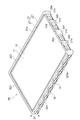
図7は、第1変形例に係る蓄電モジュールの斜視図である。図7に示されるように、第1変形例に係る蓄電モジュール4Aは、各リブ部分31〜33の形状の点で、蓄電モジュール4と相違している。各リブ部分31〜33は互いに略同様の形状を有しているため、ここでは、第1リブ部分31について説明し、第2リブ部分32及び第3リブ部分33の説明を省略する。
FIG. 7 is a perspective view of the power storage module according to the first modification. As shown in FIG. 7, the
蓄電モジュール4Aでは、第1リブ部分31は、外面221aに直交する方向から見て、互いに交差する一対の直線部分の組が、外縁部15cに沿って複数配列されたような形状を呈している。各直線部分は、外縁部15c及び積層方向D1のそれぞれに交差する方向に延在している。したがって、第1リブ部分31は、外縁部15cに沿って延在する成分と、積層方向D1に沿って延在する成分と、を有している。各組の一方の直線部分の一端は、隣り合う組の一方の直線部分の一端と接続され、各組の他方の直線部分の一端は、隣り合う組の他方の直線部分の一端と接続されているが、接続されてなくてもよい。蓄電モジュール4Aでも、第1リブ部分31は、外面221aにおいて、外縁部15cに沿って延在すると共に、積層方向D1に分布していると言える。このため、蓄電モジュール4Aでも、蓄電モジュール4と同様に、バイポーラ電極14の変形が抑制される。なお、第1リブ部分31は、複数の菱形が外縁部15cに沿って配列されたような形状を呈しているとも言える。第1リブ部分31は、外縁部15cに沿って延在すると共に、積層方向D1に配列された一対の三角波の頂点同士が互いに接続されたような形状を呈しているとも言える。
In the
図8は、第2変形例に係る蓄電モジュールの斜視図である。図8に示されるように、第2変形例に係る蓄電モジュール4Bは、各リブ部分31〜33の形状の点で、蓄電モジュール4と相違している。各リブ部分31〜33は互いに略同様の形状を有しているため、ここでは、第1リブ部分31について説明し、第2リブ部分32及び第3リブ部分33の説明を省略する。
FIG. 8 is a perspective view of the power storage module according to the second modification. As shown in FIG. 8, the
蓄電モジュール4Bでは、第1リブ部分31は、外面221aに直交する方向から見て、外縁部15cに沿う方向(電極板15の長辺方向)に延在すると共に、積層方向D1に配列された複数(ここでは3つ)の直線部分により構成されている。各直線部分は、積層方向D1において互いに離間している。蓄電モジュール4Bでも、第1リブ部分31は、外面221aにおいて、外縁部15cに沿って延在すると共に、積層方向D1に分布していると言える。このため、蓄電モジュール4Bでも、蓄電モジュール4と同様に、バイポーラ電極14の変形が抑制される。
In the
各リブ部分31〜33は、外縁部15cに沿って延在すると共に、積層方向D1に分布していればよく、蓄電モジュール4,4A,4Bにおける各リブ部分31〜33の形状に限られない。例えば、各リブ部分31〜33は、外縁部15cに沿って延在すると共に、積層方向D1に湾曲する波状(正弦波状)であってもよいし、三角波状、又は矩形波状であってもよい。各リブ部分31〜33は、各外面221a〜223aの一部に設けられていればよく、全体に設けられていなくてもよい。
The
蓄電モジュール4,4A,4Bのリブ30は、少なくとも第1リブ部分31を有していればよく、第2リブ部分32及び第3リブ部分33を有していなくてもよい。また、リブ30は、例えば、第1リブ部分31及び第2リブ部分32を有し、第3リブ部分33を有していなくてもよい。各リブ部分31〜33の形状が互いに異なっていてもよい。第1側部221及び第2側部222は、長方形枠状である外縁部15cの短辺部分に沿って延在していてもよい。外縁部15cは、正方形枠状であってもよい。
The
4,4A,4B…蓄電モジュール、11…電極積層体、12…封止体、14…バイポーラ電極、15…電極板、15a…一方面、15b…他方面、15c…外縁部、16…正極、17…負極、21…第1樹脂部、22…第2樹脂部、22h…開口、221…第1側部、222…第2側部、223…第3側部、224…第4側部、30…リブ、31…第1リブ部分、32…第2リブ部分、33…第3リブ部分、51,52…金型、V…内部空間。 4,4A, 4B ... Energy storage module, 11 ... Electrode laminate, 12 ... Sealed body, 14 ... Bipolar electrode, 15 ... Electrode plate, 15a ... One side, 15b ... Other side, 15c ... Outer edge, 16 ... Positive electrode, 17 ... Negative electrode, 21 ... 1st resin part, 22 ... 2nd resin part, 22h ... Opening, 221 ... 1st side part, 222 ... 2nd side part, 223 ... 3rd side part, 224 ... 4th side part, 30 ... Rib, 31 ... 1st rib part, 32 ... 2nd rib part, 33 ... 3rd rib part, 51, 52 ... Mold, V ... Internal space.
Claims (6)
前記電極積層体の積層方向において隣り合うバイポーラ電極間を封止する封止体と、を備え、
前記封止体は、
前記電極板の外縁部に設けられた第1樹脂部と、
前記第1樹脂部の周囲に設けられた第2樹脂部と、
前記第2樹脂部を構成する樹脂材料と同じ樹脂材料によって構成されたリブと、を有し、
前記第2樹脂部は、前記外縁部に沿って延在する第1側部、第2側部、第3側部及び第4側部を有し、
前記リブは、前記第1側部の外面に立設され、厚さが前記第1側部の厚さよりも小さい板状部材であり、前記第1側部が前記外縁部及び前記積層方向に沿って熱収縮することを抑制する第1リブ部分を有し、
前記第1側部及び前記第1リブ部分は、互いに同時に形成される射出成形体であり、
前記第1リブ部分は、前記積層方向から見て前記外縁部に沿って延在すると共に、前記外縁部に沿う方向から見て前記積層方向に沿って延在する、蓄電モジュール。 An electrode laminate in which a rectangular electrode plate, a positive electrode provided on one surface of the electrode plate, and a bipolar electrode including a negative electrode provided on the other surface of the electrode plate are laminated via a separator.
A sealant for sealing between adjacent bipolar electrodes in the stacking direction of the electrode laminate is provided.
The sealant is
A first resin portion provided on the outer edge portion of the electrode plate and
A second resin portion provided around the first resin portion and
It has ribs made of the same resin material as the resin material constituting the second resin portion, and has.
The second resin portion has a first side portion, a second side portion, a third side portion, and a fourth side portion extending along the outer edge portion.
The rib is a plate-like member that is erected on the outer surface of the first side portion and has a thickness smaller than the thickness of the first side portion , and the first side portion is along the outer edge portion and the stacking direction. Has a first rib portion that suppresses heat shrinkage
The first side portion and the first rib portion are injection molded bodies formed at the same time.
The first rib portion is adapted to extend along the outer edge portion when viewed from the laminating direction, that Mashimasu extending along the stacking direction as viewed from a direction along the outer edge portion, the power storage module.
前記リブは、前記第2側部の外面に立設され、厚さが前記第2側部の厚さよりも小さい板状部材であり、前記第2側部が前記外縁部及び前記積層方向に沿って熱収縮することを抑制する第2リブ部分を更に有し、
前記第2側部及び前記第2リブ部分は、互いに同時に形成される射出成形体であり、
前記第2リブ部分は、前記積層方向から見て前記外縁部に沿って延在すると共に、前記外縁部に沿う方向から見て前記積層方向に沿って延在する、請求項1に記載の蓄電モジュール。 The first side portion and the second side portion face each other with the electrode laminate interposed therebetween.
The rib is a plate-like member erected on the outer surface of the second side portion and having a thickness smaller than the thickness of the second side portion , and the second side portion is along the outer edge portion and the stacking direction. It also has a second rib portion that suppresses heat shrinkage.
The second side portion and the second rib portion are injection molded bodies formed at the same time.
The second rib portion is configured to extend along the outer edge portion when viewed from the laminating direction, that Mashimasu extending along the stacking direction as viewed from a direction along the outer edge portion, according to請Motomeko 1 Power storage module.
前記第1側部及び前記第2側部が前記外縁部に沿って延在する長さは、前記第3側部及び前記第4側部が前記外縁部に沿って延在する長さよりも長い、請求項1又は2に記載の蓄電モジュール。 The outer edge has a rectangular frame shape and has a rectangular frame shape.
The length of the first side portion and the second side portion extending along the outer edge portion is longer than the length of the third side portion and the fourth side portion extending along the outer edge portion. , The power storage module according to claim 1 or 2.
前記第3側部及び前記第3リブ部分は、互いに同時に形成される射出成形体であり、
前記第3リブ部分は、前記積層方向から見て前記外縁部に沿って延在すると共に、前記外縁部に沿う方向から見て前記積層方向に沿って延在し、
前記第4側部には、前記電極積層体において隣り合う前記バイポーラ電極間の複数の内部空間と連通する開口が設けられている、請求項1〜3のいずれか一項に記載の蓄電モジュール。 The rib is a plate-like member erected on the outer surface of the third side portion and having a thickness smaller than the thickness of the third side portion , and the third side portion is along the outer edge portion and the stacking direction. It also has a third rib portion that suppresses heat shrinkage.
The third side portion and the third rib portion are injection molded bodies formed at the same time.
The third rib portion is configured to extend along the outer edge portion when viewed from the stacking direction, and extend along the stacking direction as viewed from a direction along the outer edge portion,
The power storage module according to any one of claims 1 to 3, wherein the fourth side portion is provided with an opening communicating with a plurality of internal spaces between adjacent bipolar electrodes in the electrode laminate.
前記電極板の外縁部に前記第1樹脂部を設ける工程と、
前記第1樹脂部が設けられた前記バイポーラ電極を前記セパレータを介して積層することにより、前記電極積層体を形成する工程と、
矩形枠状である前記外縁部に沿って延在する第1側部、第2側部、第3側部、及び第4側部を有する前記第2樹脂部を前記第1樹脂部の周囲に設ける工程と、
板状部材であり、前記第1側部が前記外縁部及び前記積層方向に沿って熱収縮することを抑制する第1リブ部分であって、前記積層方向から見て前記外縁部に沿って延在すると共に、前記外縁部に沿う方向から見て前記積層方向に沿って延在する第1リブ部分を有し、前記第2樹脂部を構成する樹脂材料と同じ樹脂材料によって構成された前記リブを設ける工程と、を含み、
前記第2樹脂部を設ける工程と、前記リブを設ける工程とは、一対の金型を用いた射出成型により同時に行われ、前記第1樹脂部の周囲に前記第1側部が設けられると共に、前記積層方向からみて重複部分を有しておらず、厚さが前記第1側部の厚さよりも小さい前記第1リブ部分が前記第1側部の外面に立設される、蓄電モジュールの製造方法。 A first electrode laminate obtained by laminating a bipolar electrode including a rectangular electrode plate, a positive electrode provided on one surface of the electrode plate, and a negative electrode provided on the other surface of the electrode plate via a separator. A method for manufacturing a power storage module, comprising a resin portion, a second resin portion, and a sealing body having ribs and sealing between adjacent bipolar electrodes in the stacking direction of the electrode laminate.
A step of providing the first resin portion on the outer edge portion of the electrode plate, and
A step of forming the electrode laminate by laminating the bipolar electrode provided with the first resin portion via the separator.
The second resin portion having a first side portion, a second side portion, a third side portion, and a fourth side portion extending along the outer edge portion having a rectangular frame shape is placed around the first resin portion. The process of setting and
It is a plate-shaped member, and is a first rib portion that suppresses heat shrinkage of the first side portion along the outer edge portion and the stacking direction, and extends along the outer edge portion when viewed from the stacking direction. while standing, said when viewed from a direction along the outer edge along the stacking direction includes a first rib portion that Mashimasu extension, constituted by the same resin material as the resin material constituting the second resin portion and the Including the process of providing ribs
The step of providing the second resin portion and the step of providing the rib are simultaneously performed by injection molding using a pair of molds, and the first side portion is provided around the first resin portion and the first side portion is provided. Manufacture of a power storage module in which the first rib portion having no overlapping portion when viewed from the stacking direction and having a thickness smaller than the thickness of the first side portion is erected on the outer surface of the first side portion. Method.
Priority Applications (1)
| Application Number | Priority Date | Filing Date | Title |
|---|---|---|---|
| JP2017247841A JP6965731B2 (en) | 2017-12-25 | 2017-12-25 | Power storage module and manufacturing method of power storage module |
Applications Claiming Priority (1)
| Application Number | Priority Date | Filing Date | Title |
|---|---|---|---|
| JP2017247841A JP6965731B2 (en) | 2017-12-25 | 2017-12-25 | Power storage module and manufacturing method of power storage module |
Publications (3)
| Publication Number | Publication Date |
|---|---|
| JP2019114456A JP2019114456A (en) | 2019-07-11 |
| JP2019114456A5 JP2019114456A5 (en) | 2020-05-28 |
| JP6965731B2 true JP6965731B2 (en) | 2021-11-10 |
Family
ID=67221650
Family Applications (1)
| Application Number | Title | Priority Date | Filing Date |
|---|---|---|---|
| JP2017247841A Active JP6965731B2 (en) | 2017-12-25 | 2017-12-25 | Power storage module and manufacturing method of power storage module |
Country Status (1)
| Country | Link |
|---|---|
| JP (1) | JP6965731B2 (en) |
Family Cites Families (8)
| Publication number | Priority date | Publication date | Assignee | Title |
|---|---|---|---|---|
| JPS49102916U (en) * | 1972-12-25 | 1974-09-04 | ||
| US4900643A (en) * | 1988-04-08 | 1990-02-13 | Globe-Union Inc. | Lead acid bipolar battery plate and method of making the same |
| CA2118866A1 (en) * | 1993-06-21 | 1994-12-22 | Clarence A. Meadows | Bipolar battery housing and method |
| JPH07142040A (en) * | 1993-11-15 | 1995-06-02 | Honda Motor Co Ltd | Battery |
| US5508131A (en) * | 1994-04-07 | 1996-04-16 | Globe-Union Inc. | Injection molded battery containment for bipolar batteries |
| US5912090A (en) * | 1996-03-08 | 1999-06-15 | Hitachi Maxell, Ltd. | Nickel-hydrogen stacked battery pack |
| JP2013062109A (en) * | 2011-09-13 | 2013-04-04 | Furukawa Battery Co Ltd:The | Battery jar lid for lead acid battery |
| JP6743417B2 (en) * | 2016-02-29 | 2020-08-19 | 株式会社Gsユアサ | Storage element |
-
2017
- 2017-12-25 JP JP2017247841A patent/JP6965731B2/en active Active
Also Published As
| Publication number | Publication date |
|---|---|
| JP2019114456A (en) | 2019-07-11 |
Similar Documents
| Publication | Publication Date | Title |
|---|---|---|
| JP6721053B2 (en) | Power storage device and method of manufacturing power storage device | |
| JP6860091B2 (en) | Power storage module and manufacturing method of power storage module | |
| JP6805979B2 (en) | Power storage device and its manufacturing method | |
| JP7102912B2 (en) | Manufacturing method of power storage module and power storage module | |
| JP2018106967A (en) | Power storage device and manufacturing method thereof | |
| JP6911749B2 (en) | Power storage device | |
| JP6959523B2 (en) | Power storage module and manufacturing method of power storage module | |
| JP6988089B2 (en) | Power storage module and manufacturing method of power storage module | |
| JP6959514B2 (en) | Power storage module, manufacturing method of power storage module, and manufacturing method of power storage device | |
| JP6965731B2 (en) | Power storage module and manufacturing method of power storage module | |
| JP7222335B2 (en) | Storage module and method for manufacturing storage module | |
| JP7164459B2 (en) | storage module | |
| JP7070279B2 (en) | Power storage module | |
| JP7063762B2 (en) | Power storage module and manufacturing method of power storage module | |
| JP7152948B2 (en) | power storage device | |
| JP6870641B2 (en) | Battery module | |
| JP7056167B2 (en) | Power storage module and manufacturing method of power storage module | |
| JP2020145102A (en) | Manufacturing method of power storage module | |
| JP7103055B2 (en) | Power storage module and manufacturing method of power storage module | |
| JP7110875B2 (en) | Electric storage module manufacturing method and electric storage module manufacturing apparatus | |
| JP7095630B2 (en) | Power storage module manufacturing equipment and power storage module manufacturing method | |
| JP6858165B2 (en) | Power storage module and manufacturing method of power storage module | |
| JP7103033B2 (en) | Power storage module and manufacturing method of power storage module | |
| JP6965730B2 (en) | Manufacturing method of power storage module | |
| JP7172696B2 (en) | Electrode unit and power storage module |
Legal Events
| Date | Code | Title | Description |
|---|---|---|---|
| A521 | Written amendment |
Free format text: JAPANESE INTERMEDIATE CODE: A523 Effective date: 20200410 |
|
| A621 | Written request for application examination |
Free format text: JAPANESE INTERMEDIATE CODE: A621 Effective date: 20200410 |
|
| A977 | Report on retrieval |
Free format text: JAPANESE INTERMEDIATE CODE: A971007 Effective date: 20210226 |
|
| A131 | Notification of reasons for refusal |
Free format text: JAPANESE INTERMEDIATE CODE: A131 Effective date: 20210316 |
|
| A521 | Written amendment |
Free format text: JAPANESE INTERMEDIATE CODE: A523 Effective date: 20210513 |
|
| TRDD | Decision of grant or rejection written | ||
| A01 | Written decision to grant a patent or to grant a registration (utility model) |
Free format text: JAPANESE INTERMEDIATE CODE: A01 Effective date: 20210921 |
|
| A61 | First payment of annual fees (during grant procedure) |
Free format text: JAPANESE INTERMEDIATE CODE: A61 Effective date: 20211004 |
|
| R151 | Written notification of patent or utility model registration |
Ref document number: 6965731 Country of ref document: JP Free format text: JAPANESE INTERMEDIATE CODE: R151 |