JP6965211B2 - Electric motor - Google Patents
Electric motor Download PDFInfo
- Publication number
- JP6965211B2 JP6965211B2 JP2018114487A JP2018114487A JP6965211B2 JP 6965211 B2 JP6965211 B2 JP 6965211B2 JP 2018114487 A JP2018114487 A JP 2018114487A JP 2018114487 A JP2018114487 A JP 2018114487A JP 6965211 B2 JP6965211 B2 JP 6965211B2
- Authority
- JP
- Japan
- Prior art keywords
- phase
- circumferential direction
- rotating shaft
- coil
- core
- Prior art date
- Legal status (The legal status is an assumption and is not a legal conclusion. Google has not performed a legal analysis and makes no representation as to the accuracy of the status listed.)
- Active
Links
Images


Description
本発明は、電動機に関し、詳しくは、永久磁石やコイルに代えて特定形状の鉄心によって構成されたロータを有する電動機に関する。 The present invention relates to an electric motor, and more particularly to an electric motor having a rotor composed of an iron core having a specific shape instead of a permanent magnet or a coil.
従来、永久磁石やコイルに代えて特定形状の鉄心によって構成されたロータを有する電動機として、SR(Switched Reluctance)モータが知られている。このようなSRモータは、例えば、下記特許文献1に開示されている。
Conventionally, an SR (Switched Reluctance) motor is known as an electric motor having a rotor composed of an iron core having a specific shape instead of a permanent magnet or a coil. Such an SR motor is disclosed in, for example,
特許文献1に記載のSRモータは、突極鉄心を有するロータと、当該ロータを囲む円環状のステータとを備える。ロータは、その外周面からステータに向かって突出するとともに周方向に等間隔に位置する4つのロータ側突極を有している。ステータは、その内周面からロータに向かって突出するとともに周方向に等間隔に位置する6つのステータ側突極を有している。これらのステータ側突極の各々には、交番電流が供給されるコイルが巻き回されている。
The SR motor described in
このようなSRモータにおいては、コイルに交番電流を供給することで発生する磁束がロータの軸方向に対して直交する方向に広がる平面内に形成される磁気回路を通過する。具体的には、ステータ側突極に巻き回されたコイルに交番電流が供給されると、それに伴って発生する磁束が当該ステータ側突極を通過し、当該ステータ側突極に対してロータの径方向で対向する位置にあるロータ側突極からロータに入る。ロータに入ってきた磁束は、当該ロータ側突極に対してロータの径方向で反対側に位置するロータ側突極を通過した後、当該ロータ側突極に対してロータの径方向で対向する位置にあるステータ側突極からステータに入る。 In such an SR motor, the magnetic flux generated by supplying an alternating current to the coil passes through a magnetic circuit formed in a plane extending in a direction orthogonal to the axial direction of the rotor. Specifically, when an alternating current is supplied to the coil wound around the stator-side salient pole, the magnetic flux generated accordingly passes through the stator-side salient pole, and the rotor with respect to the stator-side salient pole. Enter the rotor from the rotor side salient poles that face each other in the radial direction. The magnetic flux entering the rotor passes through the rotor side salient pole located on the opposite side of the rotor side salient pole in the radial direction of the rotor, and then faces the rotor side salient pole in the radial direction of the rotor. Enter the stator from the stator side salient pole at the position.
このような磁気回路の磁気抵抗は、ロータ側突極とステータ側突極との間に形成される隙間の大きさに依存する。ここで、ロータ側突極とステータ側突極との間に形成される隙間は、ロータ側突極とステータ側突極がロータの径方向で対向しているときに最も小さくなる。 The reluctance of such a magnetic circuit depends on the size of the gap formed between the rotor side salient pole and the stator side salient pole. Here, the gap formed between the rotor side salient pole and the stator side salient pole is the smallest when the rotor side salient pole and the stator side salient pole are opposed to each other in the radial direction of the rotor.
上記SRモータでは、磁気回路の磁気抵抗が最小となる位置にロータ側突極が存在するときに電流値が極大又は極小となるように、コイルに交番電流が供給される。このように交番電流がコイルに供給されることで、ロータ側突極を引き付けるステータ側突極の位置が周方向に順次移動する。その結果、ロータが回転する。 In the SR motor, an alternating current is supplied to the coil so that the current value becomes maximum or minimum when the rotor side salient pole exists at the position where the magnetic resistance of the magnetic circuit is minimized. By supplying the alternating current to the coil in this way, the positions of the stator side salient poles that attract the rotor side salient poles move sequentially in the circumferential direction. As a result, the rotor rotates.
近年、SRモータをより高速で駆動することが求められている。しかしながら、特許文献1に記載のSRモータでは、ロータとステータとの間に跨って形成される磁気回路がロータの軸方向に対して直交する方向に広がる平面内に形成されるため、ステータのコイルに供給される交番電流の周波数よりも高い周波数でロータを回転させることができない。具体的には、特許文献1に記載のSRモータでは、ロータが4つのロータ側突極を有するとともにステータが6つのステータ側突極を有しているため、交番電流の周波数の半分の周波数でしかロータを回転させることができない。仮に、特許文献1に記載のSRモータが4つのロータ側突極を有するロータの代わりに2つのロータ側突極を有するロータを備えていたとしても、ロータを交番電流の周波数と同じ周波数でしか回転させることができない。なお、交番電流の周波数を高くすると、当該交番電流を生成するインバータの負荷が大きくなるとともにインバータの冷却機構としてより高性能なものが必要になってしまう。
In recent years, it has been required to drive an SR motor at a higher speed. However, in the SR motor described in
本発明の目的は、ステータのコイルに供給される交番電流の周波数よりも高い周波数にてロータを回転させることができる電動機を提供することである。 An object of the present invention is to provide an electric motor capable of rotating a rotor at a frequency higher than the frequency of the alternating current supplied to the coil of the stator.
上記の目的を達成するために、本願の発明者等は、コイルへの通電に伴って形成される磁気回路に着目して検討を進めた。その結果、従来のようにロータとともに回転する回転軸の軸方向に対して直交する方向に広がる平面内にて閉じられた経路を磁束が流れるように磁気回路を形成するのではなく、少なくとも回転軸の軸方向及び径方向に磁束が流れるように磁気回路を形成すればよいことに気付いた。そして、このような磁気回路を形成するには、特定の形状を有するロータと、当該ロータを囲むように回転軸の周方向に等間隔に且つ互いに独立して配置された3つのコアとを備えるとともに、これら3つのコアの各々に巻き回されたコイルに対して互いに異なる位相を有する交番電流を供給すればよいという知見を得た。本発明は、このような知見に基づいて完成されたものである。 In order to achieve the above object, the inventors of the present application have focused on a magnetic circuit formed by energizing a coil and proceeded with a study. As a result, instead of forming a magnetic circuit so that the magnetic flux flows in a closed path in a plane extending in a direction orthogonal to the axial direction of the rotating shaft rotating with the rotor as in the conventional case, at least the rotating shaft I noticed that the magnetic circuit should be formed so that the magnetic flux flows in the axial direction and the radial direction of. Then, in order to form such a magnetic circuit, a rotor having a specific shape and three cores arranged so as to surround the rotor at equal intervals in the circumferential direction of the rotation axis and independently of each other are provided. At the same time, it was found that alternating currents having different phases should be supplied to the coils wound around each of these three cores. The present invention has been completed based on such findings.
本発明の電動機は、回転軸に配置されて前記回転軸とともに回転可能なロータと、前記ロータの周囲に配置され、前記ロータとの間に作用する電磁力によって前記ロータを回転させるステータとを備え、前記ステータは、前記ロータを回転させるための交番電流が流れるU相コイルと、前記U相コイルが巻き回され、前記U相コイルへの通電に起因して発生する磁束の通過を許容するU相コアと、前記回転軸の周方向において前記U相コイルとは異なる位置に配置され、前記U相コイルを流れる交番電流とは異なる位相の交番電流が流れるV相コイルと、前記V相コイルが巻き回され、前記V相コイルへの通電に起因して発生する磁束の通過を許容するとともに、前記U相コアから分離して配置されたV相コアと、前記回転軸の周方向において前記U相コイル及び前記V相コイルとは異なる位置に配置され、前記U相コイルを流れる交番電流及び前記V相コイルを流れる交番電流とは異なる位相の交番電流が流れるW相コイルと、前記W相コイルが巻き回され、前記W相コイルへの通電に起因して発生する磁束の通過を許容するとともに、前記U相コア及び前記V相コアから分離して配置されたW相コアとを含み、前記U相コイル、前記V相コイル及び前記W相コイルは、前記回転軸の周方向に等間隔に配置され、前記U相コア、前記V相コア及び前記W相コアは、それぞれ、前記U相コイル、前記V相コイル及び前記W相コイルのうち対応するコイルが巻き回されるコイル巻回部と、前記コイル巻回部に巻き回された前記コイルの軸方向において前記コイル巻回部よりも一端側に位置して前記ロータに対向する一端側対向部と、前記コイル巻回部に巻き回された前記コイルの軸方向において前記コイル巻回部よりも他端側に位置して前記ロータに対向するとともに前記回転軸の軸方向において前記一端側対向部から離れて配置される他端側対向部とを含み、前記ロータは、前記U相コイル、前記V相コイル及び前記W相コイルへの通電に起因して発生する磁束の通過を許容する磁性材料によって形成され、前記回転軸の外周面に沿って前記回転軸の周方向に延びるとともに前記回転軸の周方向において一端及び他端を有する第1周方向部と、前記第1周方向部から前記回転軸の軸方向に離れて配置され、前記回転軸の外周面に沿って前記回転軸の周方向に延びるとともに前記回転軸の周方向において一端及び他端を有する第2周方向部と、前記回転軸の軸方向に延びて、前記第1周方向部と前記第2周方向部を連結する軸方向連結部とを含み、前記第1周方向部及び前記第2周方向部は、前記U相コイル、前記V相コイル及び前記W相コイルへの通電に起因して発生する磁束が前記ロータと前記U相コア、前記V相コア及び前記W相コアとの間に跨って形成される磁気回路を通過するように、前記ロータの回転位置に関わらず前記回転軸の軸方向及び径方向の何れかにおいて前記U相コア、前記V相コア及び前記W相コアの何れかが有する前記一端側対向部及び前記他端側対向部に対向可能な長さを有し、前記U相コイル、前記V相コイル及び前記W相コイルの各々を流れる交番電流の位相は互いに120度ずれており、前記U相コイルには、前記軸方向連結部が前記回転軸の周方向において前記U相コアと同じ位置にあるときに電流値が極大又は極小となるように交番電流が供給され、前記V相コイルには、前記軸方向連結部が前記回転軸の周方向において前記V相コアと同じ位置にあるときに電流値が極大又は極小となるように交番電流が供給され、前記W相コイルには、前記軸方向連結部が前記回転軸の周方向において前記W相コアと同じ位置にあるときに電流値が極大又は極小となるように交番電流が供給される。 The electric motor of the present invention includes a rotor arranged on a rotating shaft and rotatable together with the rotating shaft, and a stator arranged around the rotor and rotating the rotor by an electromagnetic force acting between the rotor. The stator allows the passage of a U-phase coil through which an alternating current for rotating the rotor flows and a magnetic flux generated by winding the U-phase coil and energizing the U-phase coil. The phase core, the V-phase coil arranged at a position different from the U-phase coil in the circumferential direction of the rotation axis, and the V-phase coil in which an alternating current having a phase different from the alternating current flowing through the U-phase coil flows, and the V-phase coil The V-phase core, which is wound and allows the passage of electric current generated by energization of the V-phase coil, and is arranged separately from the U-phase core, and the U in the circumferential direction of the rotation axis. A W-phase coil arranged at a position different from that of the phase coil and the V-phase coil, and an alternating current having a phase different from that of the alternating current flowing through the U-phase coil and the alternating current flowing through the V-phase coil, and the W-phase coil. Is wound around to allow the passage of electric current generated by energization of the W-phase coil, and includes the U-phase core and the W-phase core arranged separately from the V-phase core. The U-phase coil, the V-phase coil, and the W-phase coil are arranged at equal intervals in the circumferential direction of the rotation axis, and the U-phase core, the V-phase core, and the W-phase core are each the U-phase coil. A coil winding portion around which the corresponding coil of the V-phase coil and the W-phase coil is wound, and one end of the coil winding portion in the axial direction of the coil wound around the coil winding portion. One end side facing portion located on the side facing the rotor and the other end side facing the rotor in the axial direction of the coil wound around the coil winding portion and facing the rotor. The rotor also energizes the U-phase coil, the V-phase coil, and the W-phase coil, including the other-side facing portion that is arranged away from the one-side facing portion in the axial direction of the rotating shaft. It is formed of a magnetic material that allows the passage of electric current generated due to the above, extends along the outer peripheral surface of the rotating shaft in the circumferential direction of the rotating shaft, and has one end and the other end in the circumferential direction of the rotating shaft. The one circumferential direction portion and the first circumferential direction portion are arranged apart from each other in the axial direction of the rotating shaft, and extend in the circumferential direction of the rotating shaft along the outer peripheral surface of the rotating shaft and in the circumferential direction of the rotating shaft. Has one end and the other end The first circumferential direction portion and the first circumferential direction portion include a second circumferential direction portion and an axial connecting portion that extends in the axial direction of the rotating shaft and connects the first circumferential direction portion and the second circumferential direction portion. In the two-circumferential direction portion, the magnetic current generated due to the energization of the U-phase coil, the V-phase coil, and the W-phase coil is generated between the rotor and the U-phase core, the V-phase core, and the W-phase core. The U-phase core, the V-phase core, and the W-phase core in either the axial direction or the radial direction of the rotation axis regardless of the rotation position of the rotor so as to pass through the magnetic circuit formed across the space. The phase of the alternating current flowing through each of the U-phase coil, the V-phase coil, and the W-phase coil has a length that allows any of the above-mentioned one to face the one-side facing portion and the other-one facing portion. The U-phase coil is offset by 120 degrees from each other, and the alternating current is applied to the U-phase coil so that the current value becomes maximum or minimum when the axial connecting portion is at the same position as the U-phase core in the circumferential direction of the rotating shaft. Is supplied, and an alternating current is supplied to the V-phase coil so that the current value becomes maximum or minimum when the axial connecting portion is at the same position as the V-phase core in the circumferential direction of the rotating shaft. An alternating current is supplied to the W-phase coil so that the current value becomes maximum or minimum when the axial connecting portion is at the same position as the W-phase core in the circumferential direction of the rotating shaft.
上記電動機においては、周方向に等間隔に配置されたU相コア、V相コア及びW相コアとロータを利用して、少なくとも回転軸の軸方向及び径方向に磁束が流れるように磁気回路が形成される。そのため、ロータを交番電流の周波数よりも高い周波数にて回転させることができる。その理由は、以下のとおりである。 In the above motor, a magnetic circuit is used so that magnetic flux flows at least in the axial direction and the radial direction of the rotating shaft by using the U-phase core, the V-phase core, the W-phase core, and the rotor arranged at equal intervals in the circumferential direction. It is formed. Therefore, the rotor can be rotated at a frequency higher than the frequency of the alternating current. The reason is as follows.
先ず、U相コイル、V相コイル及びW相コイルへの交番電流の供給に伴って発生する磁束が通過する磁気回路について説明する。 First, a magnetic circuit through which a magnetic flux generated by supplying an alternating current to a U-phase coil, a V-phase coil, and a W-phase coil passes will be described.
コイル巻回部に巻き回されたコイルに交番電流が供給されると、それに伴って発生する磁束が一方の対向部(一端側対向部及び他端側対向部の何れか)を通過し、当該一方の対向部に対して回転軸の径方向で対向する一方の周方向部(第1周方向部及び第2周方向部の何れか)からロータに入る。ロータに入ってきた磁束は、一方の周方向部から軸方向連結部に入った後、他方の周方向部を通過し、当該他方の周方向部に対して回転軸の径方向で対向する対向部であって上記一方の対向部と対を為す他方の対向部に入る。このようにして他方の対向部に入ってきた磁束は、コイル巻回部を通過した後、一方の対向部を再び通過する。つまり、上記電動機においては、コイルに交番電流が供給されることにより、少なくとも回転軸の軸方向及び径方向に磁束が流れるように、磁気回路が形成される。 When an alternating current is supplied to the coil wound around the coil winding portion, the magnetic flux generated by the alternating current passes through one facing portion (either one facing portion or the other facing portion), and the relevant magnetic flux is generated. The rotor is entered from one circumferential portion (either the first circumferential portion or the second circumferential portion) that faces the one facing portion in the radial direction of the rotation axis. The magnetic flux that has entered the rotor enters the axial connecting portion from one circumferential portion, passes through the other circumferential portion, and faces the other circumferential portion in the radial direction of the rotation axis. It is a part and enters the other facing part which is paired with the one facing part. The magnetic flux that has entered the other facing portion in this way passes through the coil winding portion and then passes through the one facing portion again. That is, in the above motor, the magnetic circuit is formed so that the magnetic flux flows at least in the axial direction and the radial direction of the rotating shaft by supplying the alternating current to the coil.
このような磁気回路は、ロータとコアの位置関係によって、その長さが変化する。具体的には、一方の周方向部のうち回転軸の径方向において一方の対向部に対向する部分(つまり、磁束が入ってくる部分)から軸方向連結部までの距離と、他方の周方向部のうち回転軸の径方向において他方の対向部に対向する部分(つまり、磁束が出てゆく部分)から軸方向連結部までの距離が長くなるほど、磁気回路全体の長さが長くなる。 The length of such a magnetic circuit changes depending on the positional relationship between the rotor and the core. Specifically, the distance from the portion of one circumferential portion facing the opposite portion in the radial direction of the rotation axis (that is, the portion where the magnetic flux enters) to the axial connecting portion and the other circumferential direction. The longer the distance from the portion of the portion facing the other opposing portion in the radial direction of the rotating shaft (that is, the portion where the magnetic flux is emitted) to the axially connecting portion, the longer the length of the entire magnetic circuit becomes.
このように磁気回路の長さが変化すると、磁気回路の磁気抵抗が変化する。具体的には、磁気回路の長さが長くなるほど、磁気回路の磁気抵抗が大きくなる。磁気回路の磁気抵抗は、ロータの軸方向連結部とコアが回転軸の周方向において同じ位置にあるときに最小となる。 When the length of the magnetic circuit changes in this way, the magnetic resistance of the magnetic circuit changes. Specifically, the longer the length of the magnetic circuit, the greater the reluctance of the magnetic circuit. The reluctance of the magnetic circuit is minimized when the axial connection of the rotor and the core are in the same position in the circumferential direction of the rotating shaft.
ここで、上記電動機では、磁気回路の磁気抵抗が最小となる位置にロータの軸方向連結部が存在する状態で電流値が極大又は極小となるようにコイルに交番電流が供給され、且つ、このように交番電流が供給されるコイルが巻き回されたコアが互いに分離された状態で回転軸の周方向に等間隔(つまり、周方向に120度の間隔)で配置されている。そのため、交番電流の位相が180度進む毎に、つまり、交番電流の電流値が極大から極小或いは極小から極大に変化する間にロータが1回転する。その結果、上記電動機においては、交番電流の周波数の2倍の周波数にてロータを回転させることができる。 Here, in the above electric motor, an alternating current is supplied to the coil so that the current value becomes maximum or minimum in a state where the axial connection portion of the rotor exists at a position where the magnetic resistance of the magnetic circuit is minimized, and this The cores around which the coils to which the alternating current is supplied are wound are arranged at equal intervals in the circumferential direction of the rotation axis (that is, at intervals of 120 degrees in the circumferential direction) in a state where they are separated from each other. Therefore, every time the phase of the alternating current advances by 180 degrees, that is, the rotor makes one rotation while the current value of the alternating current changes from the maximum to the minimum or from the minimum to the maximum. As a result, in the above motor, the rotor can be rotated at a frequency twice the frequency of the alternating current.
上記電動機において、前記第1周方向部及び前記第2周方向部は、前記回転軸の径方向において前記U相コア、前記V相コア及び前記W相コアよりも内側に位置していてもよい。この場合、前記第1周方向部及び前記第2周方向部の一方は、当該径方向において前記U相コア、前記V相コア及び前記W相コアの何れかが有する前記一端側対向部及び前記他端側対向部の一方に対向しており、前記第1周方向部及び前記第2周方向部の他方は、当該径方向において前記U相コア、前記V相コア及び前記W相コアの何れかが有する前記一端側対向部及び前記他端側対向部の他方に対向していることが好ましい。 In the motor, the first circumferential direction portion and the second circumferential direction portion may be located inside the U-phase core, the V-phase core, and the W-phase core in the radial direction of the rotation shaft. .. In this case, one of the first circumferential direction portion and the second circumferential direction portion has the U-phase core, the V-phase core, and the W-phase core having one end side facing portion and the said portion in the radial direction. The other of the first circumferential direction portion and the second circumferential direction portion faces one of the other end side facing portions, and is any of the U phase core, the V phase core, and the W phase core in the radial direction. It is preferable that the portion facing the one end side and the other portion facing the other end side are opposed to each other.
このような態様においては、第1周方向部及び第2周方向部が回転軸の軸方向でU相コア、V相コア及びW相コアの各々に対してオーバーラップするので、回転軸の軸方向における電動機のサイズを小さくすることができる。 In such an embodiment, since the first circumferential direction portion and the second circumferential direction portion overlap each of the U-phase core, the V-phase core, and the W-phase core in the axial direction of the rotation axis, the axis of the rotation axis. The size of the motor in the direction can be reduced.
上記電動機において、前記第1周方向部及び前記第2周方向部は、前記回転軸の軸方向において前記U相コア、前記V相コア及び前記W相コアの両側に位置していてもよい。この場合、前記第1周方向部及び前記第2周方向部の一方は、当該軸方向において前記U相コア、前記V相コア及び前記W相コアの何れかが有する前記一端側対向部及び前記他端側対向部の一方に対向しており、前記第1周方向部及び前記第2周方向部の他方は、当該軸方向において前記U相コア、前記V相コア及び前記W相コアの何れかが有する前記一端側対向部及び前記他端側対向部の他方に対向していることが好ましい。 In the electric motor, the first circumferential direction portion and the second circumferential direction portion may be located on both sides of the U-phase core, the V-phase core, and the W-phase core in the axial direction of the rotation axis. In this case, one of the first circumferential direction portion and the second circumferential direction portion has the U-phase core, the V-phase core, and the W-phase core having one end side facing portion and the said portion in the axial direction. The other of the first circumferential direction portion and the second circumferential direction portion faces one of the other end side facing portions, and is any of the U phase core, the V phase core, and the W phase core in the axial direction. It is preferable that the portion facing the one end side and the other portion facing the other end side are opposed to each other.
このような態様においては、第1周方向部及び第2周方向部が回転軸の径方向でU相コア、V相コア及びW相コアの各々に対してオーバーラップするので、回転軸の径方向における電動機のサイズを小さくすることができる。 In such an embodiment, since the first circumferential direction portion and the second circumferential direction portion overlap each of the U-phase core, the V-phase core, and the W-phase core in the radial direction of the rotation shaft, the diameter of the rotation shaft The size of the motor in the direction can be reduced.
上記電動機において、好ましくは、前記第1周方向部及び前記第2周方向部は、それぞれ、前記回転軸の軸方向に積層された複数の電磁鋼板によって形成されている。 In the electric motor, preferably, the first circumferential direction portion and the second circumferential direction portion are each formed of a plurality of electromagnetic steel sheets laminated in the axial direction of the rotation shaft.
このような態様においては、第1周方向部及び第2周方向部の各々を回転軸の周方向に磁束が流れるときの渦電流の発生を抑制することができる。 In such an embodiment, it is possible to suppress the generation of eddy current when the magnetic flux flows in the circumferential direction of the rotation axis in each of the first circumferential direction portion and the second circumferential direction portion.
上記電動機において、好ましくは、前記軸方向連結部は、前記回転軸の軸方向に対して直交する方向に積層された複数の電磁鋼板によって形成されている。 In the motor, preferably, the axial connecting portion is formed of a plurality of electromagnetic steel sheets laminated in a direction orthogonal to the axial direction of the rotating shaft.
このような態様においては、軸方向連結部を回転軸の軸方向に磁束が流れるときの渦電流の発生を抑制することができる。 In such an embodiment, it is possible to suppress the generation of eddy current when the magnetic flux flows in the axial direction of the rotating shaft through the axial connecting portion.
上記電動機において、好ましくは、前記第1周方向部、前記第2周方向部及び前記軸方向連結部は互いに独立しており、前記第1周方向部及び前記第2周方向部は、それぞれ、少なくとも一部が前記回転軸の外周面に接する接触部を有しており、前記接触部には、前記回転軸の径方向内側に向かって開口するとともに前記回転軸の軸方向に延びて前記軸方向連結部の一部が嵌め込まれる溝が形成されており、前記軸方向連結部は、その一部が前記回転軸の外周面に開口して前記回転軸の軸方向に延びる溝に嵌め込まれた状態で前記第1周方向部及び前記第2周方向部の各々によって前記回転軸の径方向外側から押え込まれることにより、前記回転軸とともに回転可能となるように前記回転軸に固定されている。 In the electric motor, preferably, the first circumferential direction portion, the second circumferential direction portion, and the axial connecting portion are independent of each other, and the first circumferential direction portion and the second circumferential direction portion are respectively. At least a part of the contact portion has a contact portion in contact with the outer peripheral surface of the rotary shaft, and the contact portion opens inward in the radial direction of the rotary shaft and extends in the axial direction of the rotary shaft. A groove is formed in which a part of the directional connecting portion is fitted, and the axial connecting portion is fitted in a groove in which a part of the axial connecting portion opens on the outer peripheral surface of the rotating shaft and extends in the axial direction of the rotating shaft. In this state, each of the first circumferential direction portion and the second circumferential direction portion is pressed from the radial outside of the rotation shaft, so that the rotation shaft is fixed to the rotation shaft so as to be rotatable together with the rotation shaft. ..
このような態様においては、軸方向連結部の一部が回転軸の外周面に形成された溝に嵌め込まれた状態で、軸方向連結部の他の一部が第1周方向部及び第2周方向部の各々に形成された溝に嵌め込まれることにより、ロータが回転軸に対してその周方向に相対移動するのを規制することができる。また、軸方向連結部を機械要素であるキーとして利用することにより、第1周方向部及び第2周方向部が回転軸に対してその周方向に相対移動するのを規制することができる。 In such an embodiment, while a part of the axial connecting portion is fitted into the groove formed on the outer peripheral surface of the rotating shaft, the other part of the axial connecting portion is the first circumferential direction portion and the second peripheral direction portion. By fitting into the grooves formed in each of the circumferential portions, it is possible to restrict the rotor from moving relative to the rotation axis in the circumferential direction. Further, by using the axial connection portion as a key which is a mechanical element, it is possible to regulate the relative movement of the first circumferential direction portion and the second circumferential direction portion in the circumferential direction with respect to the rotation axis.
また、第1周方向部、第2周方向部及び軸方向連結部が互いに分離しているので、ロータが複雑な形状であっても容易に形成することができる。 Further, since the first circumferential direction portion, the second circumferential direction portion, and the axial connection portion are separated from each other, even if the rotor has a complicated shape, it can be easily formed.
上記電動機において、前記回転軸が磁性材料によって形成されていてもよい。この場合、好ましくは、前記第1周方向部及び前記第2周方向部は、それぞれ、前記回転軸の周方向の両端部分が前記回転軸の径方向において前記回転軸の外周面から離れて位置することによって前記回転軸の外周面との間に隙間を形成している。 In the motor, the rotating shaft may be formed of a magnetic material. In this case, preferably, both ends of the first circumferential direction portion and the second circumferential direction portion of the rotary shaft in the circumferential direction are located apart from the outer peripheral surface of the rotary shaft in the radial direction of the rotary shaft. By doing so, a gap is formed between the rotating shaft and the outer peripheral surface.
このような態様においては、回転軸を利用してロータに突極性を持たせることができる。この突極性は、発生トルクの向上や脈動の抑制を可能にする。具体的に、前記ロータとステータとの間の空隙中の磁場変化がトルクを生じさせるので、前記ロータが突極性を有すること、つまり前記空隙の形状を周方向に変化させる形状を有すること、は発生トルクの制御を容易にしてその向上を可能にし、また脈動を抑制する設計を可能にする。 In such an embodiment, the rotating shaft can be used to give the rotor polarity. This salient pole makes it possible to improve the generated torque and suppress pulsation. Specifically, since the change in the magnetic field in the gap between the rotor and the stator generates torque, the rotor has a salient polarity, that is, the shape of the gap is changed in the circumferential direction. It facilitates the control of the generated torque, enables its improvement, and enables a design that suppresses pulsation.
上記電動機において、前記回転軸が非磁性材料によって形成されていてもよい。 In the motor, the rotating shaft may be made of a non-magnetic material.
このような態様においては、回転軸の軽量化を実現することができるので、回転軸が磁性材料からなる場合よりも回転軸の回転に必要な電力を少なくすることができる。 In such an embodiment, the weight of the rotating shaft can be reduced, so that the electric power required for the rotation of the rotating shaft can be reduced as compared with the case where the rotating shaft is made of a magnetic material.
本発明の電動機によれば、ステータのコイルに供給される交番電流の周波数よりも高い周波数にてロータを回転させることができる。 According to the motor of the present invention, the rotor can be rotated at a frequency higher than the frequency of the alternating current supplied to the coil of the stator.
以下、添付図面を参照しながら、本発明の実施の形態について詳述する。 Hereinafter, embodiments of the present invention will be described in detail with reference to the accompanying drawings.
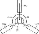
図1及び図2を参照しながら、本発明の実施の形態による電動機10について説明する。図1は、電動機10の斜視図である。図2は、図1に示す電動機10において回転軸20を取り除いた状態を示す斜視図である。
The
電動機10は、ロータ30と、ステータ40とを備える。以下、これらについて説明する。
The
ロータ30は、回転軸20に配置されて、回転軸20とともに回転する。ロータ30は、後述するコイルへの通電に起因して発生する磁束の通過を許容する磁性材料によって形成されている。本実施の形態では、ロータ30は、圧粉鉄心からなる。なお、回転軸20は、非磁性材料によって形成されている。
The
ロータ30は、第1周方向部32と、第2周方向部34と、軸方向連結部36とを含む。以下、これらについて説明する。
The
第1周方向部32及び第2周方向部34は、それぞれ、回転軸20の外周面に沿って回転軸20の周方向に略一定の断面形状(本実施の形態では、矩形形状)で延びる。第1周方向部32及び第2周方向部34は、それぞれ、回転軸20の周方向において一端及び他端を有する。別の表現をすれば、第1周方向部32及び第2周方向部34は、何れも、円環の一部を切り欠いた形状を有している。このような形状を有する第1周方向部32及び第2周方向部34においては、環状の磁路が分断されている。第1周方向部32及び第2周方向部34は、それぞれ、回転軸20の周方向において半周以上の長さに亘って延びるように形成されている。第1周方向部32及び第2周方向部34は、回転軸20の周方向において互いに同じ長さを有している。第1周方向部32の一端は、回転軸20の周方向において、第2周方向部34の一端と同じ位置にある。第1周方向部32の他端は、回転軸20の周方向において、第2周方向部34の他端と同じ位置にある。第2周方向部34は、第1周方向部32から回転軸20の軸方向に離れて配置されている。第1周方向部32及び第2周方向部34は、互いに同じ大きさ及び形状を有している。
The first
軸方向連結部36は、回転軸20の軸方向に略一定の断面形状(本実施の形態では、略矩形形状)で延びて、第1周方向部32と第2周方向部34を連結する。本実施の形態では、軸方向連結部36は、第1周方向部32と第2周方向部34に対して一体的に形成されている。
The axial connecting
ここで、第1周方向部32は、軸方向連結部36の軸方向一端部分のうち回転軸20の径方向外側の端面に接続されている。第1周方向部32は、当該端面から回転軸20の径方向外側に向かって突出している。第1周方向部32のうち回転軸20の周方向中央部分が軸方向連結部36に接続されている。
Here, the first
また、第2周方向部34は、軸方向連結部36の軸方向他端部分のうち回転軸20の径方向外側の端面に接続されている。第2周方向部34は、当該端面から回転軸20の径方向外側に向かって突出している。第2周方向部34のうち回転軸20の周方向中央部分が軸方向連結部36に接続されている。
Further, the second
なお、第1周方向部32、第2周方向部34及び軸方向連結部36の各々の断面は、後述する磁束がロータ30を通過するときに部分的な磁気飽和が生じるのを回避するように、同程度の大きさで形成される。
The cross sections of the first
ステータ40は、ロータ30の周囲に配置され、ロータ30との間に作用する電磁力によってロータ30を回転させる。ステータ40は、例えば、図示しないハウジングに収容された状態で当該ハウジングに固定される。ステータ40は、U相コイル42Uと、U相コア44Uと、V相コイル42Vと、V相コア44Vと、W相コイル42Wと、W相コア44Wとを含む。
The
U相コイル42U、V相コイル42V及びW相コイル42Wは、回転軸20の周方向に等間隔に配置されている。別の表現をすれば、U相コイル42U、V相コイル42V及びW相コイル42Wは、回転軸20の周方向において互いに異なる位置に配置されている。
The
U相コイル42U、V相コイル42V及びW相コイル42Wの各々には、ロータ30を回転させるための交番電流が流れる。U相コイル42U、V相コイル42V及びW相コイル42Wの各々を流れる交番電流の位相は互いに120度ずれている。つまり、U相コイル42U、V相コイル42V及びW相コイル42Wの各々を流れる交番電流は、互いに異なる位相を有している。なお、U相コイル42U、V相コイル42V及びW相コイル42Wの各々を流れる交番電流の詳細については、後述する。
An alternating current for rotating the
U相コア44U、V相コア44V及びW相コア44Wは、回転軸20の周方向に等間隔に配置されている。別の表現をすれば、U相コア44U、V相コア44V及びW相コア44Wは、互いに分離して配置されている。
The
U相コア44Uには、U相コイル42Uが巻き回されている。U相コア44Uは、U相コイル42Uへの通電に起因して発生する磁束の通過を許容する。
A
V相コア44Vには、V相コイル42Vが巻き回されている。V相コア44Vは、V相コイル42Vへの通電に起因して発生する磁束の通過を許容する。
A V-
W相コア44Wには、W相コイル42Wが巻き回されている。W相コア44Wは、W相コイル42Wへの通電に起因して発生する磁束の通過を許容する。
A W-
U相コア44U、V相コア44V及びW相コア44Wは、それぞれ、コイル巻回部441と、一端側対向部442と、他端側対向部443とを含む。以下、これらについて説明する。
The
コイル巻回部441には、U相コイル42U、V相コイル42V及びW相コイル42Wのうち対応するコイルが巻き回されている。コイル巻回部441は、回転軸20の軸方向に略一定の矩形断面でストレートに延びている。
A coil of the
一端側対向部442は、コイル巻回部441に巻き回されたコイルの軸方向においてコイル巻回部441よりも一端側に位置してロータ30に対向する。一端側対向部442は、コイル巻回部441の一端から径方向内側に延び出している。一端側対向部442は、本体部4421と先端部4422とを含む。
The one-end
本体部4421は、コイル巻回部441の一端から径方向内側に向かって略一定の矩形断面でストレートに延びている。先端部4422は、本体部4421の先端に設けられている。先端部4422は、回転軸20の外周面に沿って回転軸20の周方向に延びている。先端部4422は、本体部4421から回転軸20の周方向両側に突出するように延びている。
The
他端側対向部443は、コイル巻回部441に巻き回されたコイルの軸方向においてコイル巻回部441よりも他端側に位置してロータ30に対向する。他端側対向部443は、回転軸20の軸方向において一端側対向部442から離れて配置されている。他端側対向部443は、コイル巻回部441の他端から回転軸20の径方向内側に延び出している。他端側対向部443は、本体部4431と先端部4432とを含む。
The other end
本体部4431は、コイル巻回部441の他端から径方向内側に向かって略一定の矩形断面でストレートに延びている。先端部4432は、本体部4431の先端に設けられている。先端部4432は、回転軸20の外周面に沿って回転軸20の周方向に延びている。先端部4432は、本体部4431から回転軸20の周方向両側に突出するように延びている。
The
ここで、第1周方向部32及び第2周方向部34は、回転軸20の径方向においてU相コア44U、V相コア44V及びW相コア44Wよりも内側に位置するとともに当該径方向においてU相コア44U、V相コア44V及びW相コア44Wの何れかが有する一端側対向部442及び他端側対向部443に対向している。具体的には、第1周方向部32が一端側対向部442に対して回転軸20の径方向で対向しており、第2周方向部34が他端側対向部443に対して回転軸の径方向で対向している。第1周方向部32は、一端側対向部442に対して回転軸20の径方向で対向するとともに一端側対向部442における対向面との間に所定の隙間を形成する外周面320を有している。第2周方向部34は、他端側対向部443に対して回転軸20の径方向で対向するとともに他端側対向部443における対向面との間に所定の隙間を形成する外周面340を有している。
Here, the first
また、第1周方向部32及び第2周方向部34は、U相コイル42U、V相コイル42V及びW相コイル42Wに交番電流が供給されることで発生する磁束がロータ30とU相コア44U、V相コア44V及びW相コア44Wとの間に跨って形成される磁気回路を通過するように、ロータ30の回転位置に関わらず回転軸20の径方向においてU相コア44U、V相コア44V及びW相コア44Wの何れかが有する一端側対向部442及び他端側対向部443に対向可能な長さを有している。具体的には、第1周方向部32はU相コア44U、V相コア44V及びW相コア44Wの何れかが有する一端側対向部442に対して回転軸20の径方向で対向可能な長さを有しており、第2周方向部34がU相コア44U、V相コア44V及びW相コア44Wの何れかが有する他端側対向部443に対して回転軸の径方向で対向可能な長さを有している。
Further, in the first
また、U相コイル42Uには、ロータ30の軸方向連結部36が回転軸20の周方向においてU相コア44Uと同じ位置にあるときに電流値が極大又は極小となるように交番電流が供給される。ここで、軸方向連結部36が回転軸20の周方向においてU相コア44Uと同じ位置にある状態とは、軸方向連結部36が回転軸20の周方向においてU相コア44Uが有するコイル巻回部441と同じ位置にある状態をいう。
Further, an alternating current is supplied to the
また、V相コイル42Vには、ロータ30の軸方向連結部36が回転軸20の周方向においてV相コア44Vと同じ位置にあるときに電流値が極大又は極小となるように交番電流が供給される。ここで、軸方向連結部36が回転軸20の周方向においてV相コア44Vと同じ位置にある状態とは、軸方向連結部36が回転軸20の周方向においてV相コア44Vが有するコイル巻回部441と同じ位置にある状態をいう。
Further, an alternating current is supplied to the V-
また、W相コイル42Wには、ロータ30の軸方向連結部36が回転軸20の周方向においてW相コア44Wと同じ位置にあるときに電流値が極大又は極小となるように交番電流が供給される。ここで、軸方向連結部36が回転軸20の周方向においてW相コア44Wと同じ位置にある状態とは、軸方向連結部36が回転軸20の周方向においてW相コア44Wが有するコイル巻回部441と同じ位置にある状態をいう。
Further, an alternating current is supplied to the W-
図3及び図4を参照しながら、電動機10においてロータ30とステータ40との間に跨って形成される磁気回路について説明する。図3は、電動機10を回転軸20の軸方向から見たときのロータ30とU相コア44U、V相コア44V及びW相コア44Wとの位置関係を示す模式図である。図4は、図3におけるIV−IV方向に相当する断面を示す説明図であって、U相コア44Uとロータ30との間に形成される磁気回路を示す説明図である。なお、図4では、U相コア44Uに巻き回されたU相コイル42Uも図示している。
A magnetic circuit formed between the
以下、U相コイル42Uに交番電流を供給したときにロータ30とU相コア44Uとの間に形成される磁気回路について説明するが、V相コイル42Vに交番電流を供給したときにロータ30とV相コア44Vとの間に形成される磁気回路や、W相コイル42Wに交番電流を供給したときにロータ30とW相コア44Wとの間に形成される磁気回路については、U相コイル42Uへの通電に起因して形成される磁気回路と同様であるから、それらの詳細な説明については省略する。
Hereinafter, the magnetic circuit formed between the
先ず、U相コイル42Uに交番電流が供給されると、磁束が発生する。当該磁束は、U相コイル42Uが巻き回されたコイル巻回部441(U相コア44Uが有するコイル巻回部441)を通過した後、一方の対向部(一端側対向部442及び他端側対向部443)からロータ30に入る。具体的には、ロータ30のうち一方の対向部に対して回転軸20の径方向で対向する一方の周方向部(第1周方向部32及び第2周方向部34の何れか)からロータ30に入る。このようにしてロータ30に入ってきた磁束は、一方の周方向部から軸方向連結部36に入った後、他方の周方向部を通過して、U相コア44Uに戻る。具体的には、当該他方の周方向部に対して回転軸20の径方向で対向する対向部であって上記一方の対向部と対を為す他方の対向部に入る。このようにして他方の対向部に入ってきた磁束は、U相コア44Uが有するコイル巻回部441を再び通過する。つまり、電動機10においては、U相コイル42Uに交番電流が供給されることにより、少なくとも回転軸20の軸方向及び径方向に磁束が流れるように、磁気回路が形成される。
First, when an alternating current is supplied to the
このようなU相コイル42Uへの通電に起因して形成される磁気回路は、ロータ30とU相コア44の位置関係によって、その長さが変化する。具体的には、一方の周方向部のうち回転軸20の径方向において一方の対向部に対向する部分(つまり、磁束が入ってくる部分)から軸方向連結部36までの距離(つまり、回転軸20の周方向での距離)と、他方の周方向部のうち回転軸20の径方向において他方の対向部に対向する部分(つまり、磁束が出てゆく部分)から軸方向連結部36までの距離(つまり、回転軸20の周方向での距離)が長くなるほど、磁気回路全体の長さが長くなる。
The length of the magnetic circuit formed by energizing the
このように磁気回路の長さが変化すると、磁気回路の磁気抵抗が変化する。具体的には、磁気回路の長さが長くなるほど、磁気回路の磁気抵抗が大きくなる。磁気回路の磁気抵抗は、ロータ30の軸方向連結部36とU相コア44Uのコイル巻回部441とが回転軸20の周方向において同じ位置にあるときに最小となる。
When the length of the magnetic circuit changes in this way, the magnetic resistance of the magnetic circuit changes. Specifically, the longer the length of the magnetic circuit, the greater the reluctance of the magnetic circuit. The magnetic resistance of the magnetic circuit is minimized when the axial connecting
ここで、電動機10では、磁気回路の磁気抵抗が最小となる位置にロータ30の軸方向連結部36が存在する状態で電流値が極大又は極小となるようにU相コイル42U、V相コイル42V及びW相コイル42Wの各々に交番電流が供給され、且つ、このように交番電流が供給されるU相コイル42U、V相コイル42V及びW相コイル42Wが巻き回されたU相コア44U、V相コア44V及びW相コア44Wが互いに分離された状態で回転軸20の周方向に等間隔(つまり、周方向に120度の間隔)で配置されている。そのため、交番電流の位相が180度進む毎に、つまり、交番電流の電流値が極大から極小或いは極小から極大に変化する間にロータ30が1回転する。その結果、電動機10においては、交番電流の周波数の2倍の周波数にてロータ30を回転させることができる。
Here, in the
図5〜図12を参照しながら、電動機10において交番電流の周波数の2倍の周波数にてロータ30を回転させることができる理由について、もう少し詳しく説明する。図5は、U相コイル42U、V相コイル42V及びW相コイル42Wの各々に供給される交番電流の位相と振幅との関係を示すグラフである。図6〜図12は、それぞれ、図5に示す位相P0〜P6でのロータ30とU相コア44U、V相コア44V及びW相コア44Wとの位置関係を示す模式図である。
With reference to FIGS. 5 to 12, the reason why the
位相P0(図5参照)では、U相コイル42Uに供給される交番電流の電流値が極大値であり、図6に示す位置にてロータ30が安定する。位相P0よりも30度進んだ位相である位相P1(図5参照)では、W相コイル42Wに供給される交番電流の電流値がゼロであり、図7に示す位置にてロータ30が安定する。位相P1よりも30度進んだ位相である位相P2(図5参照)では、V相コイル42Vに供給される交番電流の電流値が極小値であり、図8に示す位置にてロータ30が安定する。位相P2よりも30度進んだ位相である位相P3(図5参照)では、U相コイル42Uに供給される交番電流の電流値がゼロであり、図9に示す位置にてロータ30が安定する。位相P3よりも30度進んだ位相である位相P4(図5参照)では、W相コイル42Wに供給される交番電流の電流値が極大値であり、図10に示す位置にてロータ30が安定する。位相P4よりも30度進んだ位相である位相P5(図5参照)では、V相コイル42Vに供給される交番電流の電流値がゼロであり、図11に示す位置にてロータ30が安定する。位相P5よりも30度進んだ位相である位相P6(図5参照)では、U相コイル42Uに供給される交番電流の電流値が極小値であり、図12に示す位置にてロータ30が安定する。
In the phase P0 (see FIG. 5), the current value of the alternating current supplied to the
ここで、ある位相(例えば、位相P3)でのロータ30の位置は、当該位相よりも30度遅れた位相(例えば、位相P2)でのロータ30の位置よりも60度進んでいる。つまり、U相コイル42U、V相コイル42V及びW相コイル42Wの各々に供給される交番電流の位相が30度進むごとに、ロータ30が60度回転する。
Here, the position of the
したがって、電動機10においては、交番電流の周波数の2倍の周波数にてロータ30を回転させることができる。
Therefore, in the
また、電動機10においては、ロータ30の第1周方向部32がU相コア44U、V相コア44V及びW相コア44Wの何れかが有する一端側対向部442に対して回転軸20の径方向で対向するとともに、ロータ30の第2周方向部34がU相コア44U、V相コア44V及びW相コア44Wの何れかが有する他端側対向部443に対して回転軸20の径方向で対向する。そのため、第1周方向部32を一端側対向部442に対して軸方向でオーバーラップさせることができるとともに、第2周方向部34を他端側対向部443に対して軸方向でオーバーラップさせることができる。その結果、電動機10における回転軸20の軸方向での長さを短くすることができる。
Further, in the
[実施の形態の変形例1]
図13を参照しながら、上記実施の形態の変形例1に係る電動機10Aについて説明する。図13は、実施の形態の変形例1に係る電動機10Aを示す斜視図である。
[
The
上記実施の形態では、圧粉鉄心からなるロータ30が採用されているが、図13に示す変形例1では、複数の電磁鋼板321、341、361を用いて形成されたロータ30Aが採用されている。
In the above embodiment, the
ロータ30Aは、第1周方向部32A、第2周方向部34A及び軸方向連結部36Aを有している。第1周方向部32A、第2周方向部34A及び軸方向連結部36Aは、それぞれ、複数の電磁鋼板321、341、361を積層したものである。
The
具体的には、第1周方向部32A及び第2周方向部34Aでは、複数の電磁鋼板321、341が回転軸20の軸方向に積層されている。第1周方向部32A及び第2周方向部34Aを形成する複数の電磁鋼板321、341は、積層された状態で接着されている。複数の電磁鋼板321、341の表面はそれぞれ絶縁層で覆われている。
Specifically, in the first
また、軸方向連結部36Aでは、複数の電磁鋼板361が回転軸20の軸方向に対して直交する方向に積層されている。軸方向連結部36Aを形成する複数の電磁鋼板361は、積層された状態で接着されている。複数の電磁鋼板361の表面はそれぞれ絶縁層で覆われている。
Further, in the axial
なお、図13に示す例では、第1周方向部32A、第2周方向部34A及び軸方向連結部36Aの各々が複数の電磁鋼板を積層することで形成されているが、例えば、第1周方向部32A、第2周方向部34A及び軸方向連結部36Aの幾つかを複数の電磁鋼板を積層することで形成し、残りを圧粉鉄心で形成してもよい。
In the example shown in FIG. 13, each of the first
電動機10Aにおいては、第1周方向部32A及び第2周方向部34Aがそれぞれ回転軸20の軸方向に積層された複数の電磁鋼板321、341によって形成されており、当該積層された複数の電磁鋼板321、341の間には、各電磁鋼板の表面を覆う絶縁層が存在している。そのため、第1周方向部32A及び第2周方向部34Aの各々を回転軸20の周方向に磁束が流れるときの渦電流の発生を抑制することができる。
In the
電動機10Aにおいては、軸方向連結部36Aが回転軸20の軸方向に対して直交する方向に積層された複数の電磁鋼板361によって形成されており、当該積層された複数の電磁鋼板361の間には、各電磁鋼板の表面を覆う絶縁層が存在している。そのため、軸方向連結部36Aを回転軸20の軸方向に磁束が流れるときの渦電流の発生を抑制することができる。
In the
電動機10Aにおいては、第1周方向部32A、第2周方向部34A及び軸方向連結部36Aがそれぞれ積層された複数の電磁鋼板321、341、361によって形成されている。そのため、例えば圧粉からなるものに比べて前記ロータ30Aの透磁率を大きくすることができる。その結果、より大きなトルクを発生させることができる。
In the
[実施の形態の変形例2]
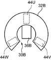
図14及び図15を参照しながら、上記実施の形態の変形例2に係る電動機について説明する。図14は、本変形例に係る電動機を回転軸の軸方向から見たときのロータ30BとU相コア44U、V相コア44V及びW相コア44Wとの位置関係を示す模式図である。図15は、図14におけるXV−XV方向に相当する断面を示す説明図であって、U相コア44Uとロータ30との間に形成される磁気回路を示す説明図である。なお、図15では、U相コア44Uに巻き回されたU相コイル42Uも図示している。
[Modification 2 of the embodiment]
The electric motor according to the second modification of the above embodiment will be described with reference to FIGS. 14 and 15. FIG. 14 is a schematic view showing the positional relationship between the
上記実施の形態に係る電動機10では、ロータ30の第1周方向部32がU相コア44U、V相コア44V及びW相コア44Wの何れかが有する一端側対向部442に対して回転軸20の径方向で対向するとともに、ロータ30の第2周方向部34がU相コア44U、V相コア44V及びW相コア44Wの何れかが有する他端側対向部443に対して回転軸20の径方向で対向している。
In the
これに対して、上記実施の形態の変形例2に係る電動機では、ロータ30Bの第1周方向部32BがU相コア44U、V相コア44V及びW相コア44Wの各々が有する一端側対向部442よりも回転軸20の軸方向において外側に位置している。これにより、第1周方向部32BがU相コア44U、V相コア44V及びW相コア44Wの何れかが有する一端側対向部442に対して回転軸20の軸方向で対向している。そのため、第1周方向部32Bを一端側対向部442に対して径方向でオーバーラップさせることができる。
On the other hand, in the electric motor according to the second modification of the above embodiment, the first
また、ロータ30の第2周方向部34BがU相コア44U、V相コア44V及びW相コア44Wの各々が有する他端側対向部443よりも回転軸20の軸方向において外側に位置している。これにより、第2周方向部34BがU相コア44U、V相コア44V及びW相コア44Wの何れかが有する他端側対向部443に対して回転軸20の軸方向で対向している。そのため、第2周方向部34Bを他端側対向部443に対して径方向でオーバーラップさせることができる。
Further, the second
したがって、本変形例に係る電動機においては、回転軸20の径方向での長さを短くすることができる。
Therefore, in the electric motor according to the present modification, the length of the
[実施の形態の変形例3]
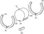
図16及び図17を参照しながら、上記実施の形態の変形例3に係る電動機10Cについて説明する。図16は、実施の形態の変形例3に係る電動機10Cを示す斜視図である。図17は、電動機10Cを構成するロータ30Cの分解斜視図である。なお、図17では、理解を容易にするために、ロータ30Cの他に回転軸20も図示している。
[Modification 3 of the embodiment]
The
電動機10Cでは、ロータ30の代わりに、ロータ30Bを備える。ロータ30Bを構成する第1周方向部32C、第2周方向部34C及び軸方向連結部36Cは、互いに独立している。つまり、第1周方向部32C、第2周方向部34C及び軸方向連結部36Cは、互いに分離可能である。
The
第1周方向部32C、第2周方向部34C及び軸方向連結部36Cは、圧粉鉄心からなるものであってもよいし、複数の電磁鋼板が積層されたものであってもよい。第1周方向部32C及び第2周方向部34Cが積層された複数の電磁鋼板からなる場合、当該複数の電磁鋼板は回転軸20の軸方向に積層される。軸方向連結部36Cが積層された複数の電磁鋼板からなる場合、当該複数の電磁鋼板は回転軸20の軸方向に対して直交する方向に積層される。
The first
第1周方向部32Cは、回転軸20の外周面に接する接触部321を有している。接触部321には、溝3211が形成されている。溝3211は、回転軸20の径方向内側に向かって開口するとともに、回転軸20の軸方向に延びている。溝3211は、第1周方向部32Cが延びる方向(回転軸20の周方向)において、第1周方向部32Cの中央部分に位置している。
The first
第2周方向部34Cは、回転軸20の外周面に接する接触部341を有している。接触部341には、溝3411が形成されている。溝3411は、回転軸20の径方向内側に向かって開口するとともに、回転軸20の軸方向に延びている。溝3411は、第2周方向部34Cが延びる方向(回転軸20の周方向)において、第2周方向部34Cの中央部分に位置している。
The second
軸方向連結部36Cは、回転軸20の外周面に固定されている。具体的には、軸方向連結部36Cの一部が回転軸20の外周面に形成された溝201に嵌め込まれている。溝201は、回転軸20の外周面に開口して、回転軸20の軸方向に延びている。
The axial connecting
軸方向連結部36Cの一部が回転軸20の外周面に形成された溝201に嵌め込まれた状態で、第1周方向部32C及び第2周方向部34Cが軸方向連結部36Cに組み付けられている。具体的には、第1周方向部32Cの溝3211に対して軸方向連結部36Cの一端部分が嵌め込まれることにより、第1周方向部32Cが軸方向連結部36Cに組み付けられている。第2周方向部34Cの溝3411に対して軸方向連結部36Cの他端部分が嵌め込まれることにより、第2周方向部34Cが軸方向連結部36Cに組み付けられている。
The first
このようにして第1周方向部32C及び第2周方向部34Cがそれぞれ軸方向連結部36Cに組み付けられることにより、軸方向連結部36Cが回転軸20の径方向外側から第1周方向部32C及び第2周方向部34Cによって押え込まれる。その結果、ロータ30が回転軸20とともに回転可能となるように回転軸20に固定される。
In this way, the first
ここで、図16及び図17に示す例では、回転軸20が磁性材料によって形成されている。また、回転軸20の外周面は、第1外周面20Aと、第2外周面20Bとを含む。
Here, in the examples shown in FIGS. 16 and 17, the rotating
第1外周面20Aは、回転軸20の径方向において第1周方向部32C及び第2周方向部34Cに接触する。第1外周面20Aには、溝201が形成されている。
The first outer
第2外周面20Bは、第1外周面20Aよりも回転軸20の径方向で内側に位置している。つまり、第2外周面20Bは、第1外周面20Aよりも小さな直径で形成されている。そのため、第1外周面20Aと第2外周面20Bとの間には、段差が形成されている。第2外周面20Bは、回転軸20の外周面のうち第1外周面20Aを除いた領域に形成されている。第2外周面20Bにおける回転軸20の周方向での長さは、第1外周面20Aにおける回転軸20の周方向での長さよりも大きい。
The second outer
このように回転軸20の外周面が第1外周面20Aと第2外周面20Bとを有することにより、第1周方向部32Cにおける回転軸20の周方向の両端部分がそれぞれ回転軸20の径方向において回転軸20の外周面における第2外周面20Bから離れているとともに、第2周方向部34Cにおける回転軸20の周方向の両端部分がそれぞれ回転軸20の径方向において回転軸20の外周面における第2外周面20Bから離れている。つまり、第1周方向部32Cにおける回転軸20の周方向の両端部分は、それぞれ、回転軸20の外周面における第2外周面20Bとの間に隙間を形成している。また、第2周方向部34Cにおける回転軸20の周方向の両端部分も、それぞれ、回転軸20の径方向において回転軸20の外周面における第2外周面20Bとの間に隙間を形成している。
As described above, since the outer peripheral surface of the
電動機10Cにおいては、軸方向連結部36Cの一部が回転軸20の外周面における第1外周面20Aに形成された溝201に嵌め込まれた状態で、軸方向連結部36Cの他の一部が第1周方向部32C及び第2周方向部34Cの各々に形成された溝321、341に嵌め込まれることにより、ロータ30が回転軸20に対してその周方向に相対移動するのを規制することができる。
In the
電動機10Cにおいては、軸方向連結部36Cを利用して、第1周方向部32C及び第2周方向部34Cの回転軸20に対する相対回転を規制することができる。
In the
電動機10Cにおいては、第1周方向部32C、第2周方向部34C及び軸方向連結部36Cが互いに分離しているので、ロータ30が複雑な形状であっても容易に形成することができる。
In the
電動機10Cにおいては、回転軸20が磁性材料によって形成されているとともに、第1周方向部32C及び第2周方向部34Cは、それぞれ、回転軸20の周方向の両端部分が回転軸20の径方向において回転軸20の外周面における第2外周面20Bから離れて位置することによって回転軸20の外周面における第2外周面20Bとの間に隙間を形成している。そのため、回転軸20を利用してロータ30に突極性を持たせることができる。この突極性は、発生トルクの向上や脈動の抑制を可能にする。具体的に、前記ロータ30とステータ40との間の空隙中の磁場変化がトルクを生じさせるので、前記ロータ30が突極性を有すること、つまり前記空隙の形状を周方向に変化させる形状を有すること、は発生トルクの制御を容易にしてその向上を可能にし、また脈動を抑制する設計を可能にする。
In the
なお、図16に示す例では、磁性材料で形成された回転軸20と第1周方向部32C及び第2周方向部34Cとの間に隙間を形成するために、回転軸20の外周面が第1外周面20Aと第2外周面20Bとを有しているが、例えば、回転軸20が非磁性材料で形成されている場合には、図18に示すように、回転軸20の外周面が溝201以外に段差を有していないようにしてもよい。
In the example shown in FIG. 16, the outer peripheral surface of the
[実施の形態の変形例4]
例えば、ロータが、非磁性材料で形成されて回転軸20の周方向に延びるとともに第1周方向部32の一端及び他端を接続する第1接続部を有するとともに、非磁性材料で形成されて回転軸20の周方向に延びるとともに第2周方向部34の一端及び他端を接続する第2接続部を有するようにしてもよい。この場合、ロータの軸方向両端部分を環状にすることができるので、ロータの回転バランスを向上させることができる。
[Modification 4 of the embodiment]
For example, the rotor is made of a non-magnetic material, extends in the circumferential direction of the
以上、本発明の実施の形態について詳述してきたが、これらはあくまでも例示であって、本発明は、上述の実施の形態の記載によって、何等、限定的に解釈されるものではない。 Although the embodiments of the present invention have been described in detail above, these are merely examples, and the present invention is not to be interpreted in a limited manner by the above description of the embodiments.
例えば、上記実施の形態では、U相コイル、V相コイル及びW相コイルの各々が回転軸の軸方向に延びるコイル巻回部に巻き回されているが、例えば、U相コイル、V相コイル及びW相コイルの各々が回転軸の径方向に延びるコイル巻回部に巻き回されていてもよい。 For example, in the above embodiment, each of the U-phase coil, the V-phase coil, and the W-phase coil is wound around a coil winding portion extending in the axial direction of the rotation axis. Each of the W-phase coil and the W-phase coil may be wound around a coil winding portion extending in the radial direction of the rotation shaft.
例えば、上記実施の形態では、U相コア、V相コア及びW相コアの各々が有する一端側対向部及び他端側対向部において先端部が設けられているが、当該先端部はなくてもよい。 For example, in the above embodiment, the tip portions are provided at one end side facing portion and the other end side facing portion of each of the U phase core, the V phase core, and the W phase core, but even if the tip portion is not provided. good.
例えば、上記実施の形態において、ロータを覆う筒状又は管状の部材を採用してもよい。この場合、ロータの強度を確保することができる。 For example, in the above embodiment, a tubular or tubular member that covers the rotor may be adopted. In this case, the strength of the rotor can be ensured.
例えば、一端側対向部及び他端側対向部の一方が第1周方向部及び第2周方向部の一方に対して径方向で対向するとともに、一端側対向部及び他端側対向部の他方が第1周方向部及び第2周方向部の他方に対して軸方向で対向してもよい。 For example, one of the one end side facing portion and the other end side facing portion is radially opposed to one of the first circumferential direction portion and the second circumferential direction portion, and the other end side facing portion and the other end side facing portion are opposed to each other. May face the other of the first circumferential direction portion and the second circumferential direction portion in the axial direction.
10 電動機
20 回転軸
30 ロータ
32 第1周方向部
34 第2周方向部
36 軸方向連結部
40 ステータ
42U U相コイル
42V V相コイル
42W W相コイル
44U U相コア
44V V相コア
44W W相コア
441 コイル巻回部
442 一端側対向部
443 他端側対向部
10
Claims (8)
前記ロータの周囲に配置され、前記ロータとの間に作用する電磁力によって前記ロータを回転させるステータとを備え、
前記ステータは、
前記ロータを回転させるための交番電流が流れるU相コイルと、
前記U相コイルが巻き回され、前記U相コイルへの通電に起因して発生する磁束の通過を許容するU相コアと、
前記回転軸の周方向において前記U相コイルとは異なる位置に配置され、前記U相コイルを流れる交番電流とは異なる位相の交番電流が流れるV相コイルと、
前記V相コイルが巻き回され、前記V相コイルへの通電に起因して発生する磁束の通過を許容するとともに、前記U相コアから分離して配置されたV相コアと、
前記回転軸の周方向において前記U相コイル及び前記V相コイルとは異なる位置に配置され、前記U相コイルを流れる交番電流及び前記V相コイルを流れる交番電流とは異なる位相の交番電流が流れるW相コイルと、
前記W相コイルが巻き回され、前記W相コイルへの通電に起因して発生する磁束の通過を許容するとともに、前記U相コア及び前記V相コアから分離して配置されたW相コアとを含み、
前記U相コイル、前記V相コイル及び前記W相コイルは、前記回転軸の周方向に等間隔に配置され、
前記U相コア、前記V相コア及び前記W相コアは、それぞれ、
前記U相コイル、前記V相コイル及び前記W相コイルのうち対応するコイルが巻き回されるコイル巻回部と、
前記コイル巻回部に巻き回された前記コイルの軸方向において前記コイル巻回部よりも一端側に位置して前記ロータに対向する一端側対向部と、
前記コイル巻回部に巻き回された前記コイルの軸方向において前記コイル巻回部よりも他端側に位置して前記ロータに対向するとともに前記回転軸の軸方向において前記一端側対向部から離れて配置される他端側対向部とを含み、
前記ロータは、
前記U相コイル、前記V相コイル及び前記W相コイルへの通電に起因して発生する磁束の通過を許容する磁性材料によって形成され、
前記回転軸の外周面に沿って前記回転軸の周方向に延びるとともに前記回転軸の周方向において一端及び他端を有する第1周方向部と、
前記第1周方向部から前記回転軸の軸方向に離れて配置され、前記回転軸の外周面に沿って前記回転軸の周方向に延びるとともに前記回転軸の周方向において一端及び他端を有する第2周方向部と、
前記回転軸の軸方向に延びて、前記第1周方向部と前記第2周方向部を連結する軸方向連結部とを含み、
前記第1周方向部及び前記第2周方向部は、前記U相コイル、前記V相コイル及び前記W相コイルへの通電に起因して発生する磁束が前記ロータと前記U相コア、前記V相コア及び前記W相コアとの間に跨って形成される磁気回路を通過するように、前記ロータの回転位置に関わらず前記回転軸の軸方向及び径方向の何れかにおいて前記U相コア、前記V相コア及び前記W相コアの何れかが有する前記一端側対向部及び前記他端側対向部に対向可能な長さを有し、
前記U相コイル、前記V相コイル及び前記W相コイルの各々を流れる交番電流の位相は互いに120度ずれており、
前記U相コイルには、前記軸方向連結部が前記回転軸の周方向において前記U相コアと同じ位置にあるときに電流値が極大又は極小となるように交番電流が供給され、
前記V相コイルには、前記軸方向連結部が前記回転軸の周方向において前記V相コアと同じ位置にあるときに電流値が極大又は極小となるように交番電流が供給され、
前記W相コイルには、前記軸方向連結部が前記回転軸の周方向において前記W相コアと同じ位置にあるときに電流値が極大又は極小となるように交番電流が供給される、電動機。 A rotor that is arranged on a rotating shaft and can rotate with the rotating shaft,
It is provided with a stator which is arranged around the rotor and rotates the rotor by an electromagnetic force acting between the rotor and the rotor.
The stator is
A U-phase coil through which an alternating current for rotating the rotor flows, and
A U-phase core in which the U-phase coil is wound and allows the passage of magnetic flux generated due to energization of the U-phase coil, and a U-phase core.
A V-phase coil that is arranged at a position different from that of the U-phase coil in the circumferential direction of the rotation axis and has an alternating current having a phase different from that of the alternating current flowing through the U-phase coil.
The V-phase coil is wound to allow the passage of magnetic flux generated by energization of the V-phase coil, and the V-phase core is arranged separately from the U-phase core.
It is arranged at a position different from the U-phase coil and the V-phase coil in the circumferential direction of the rotating shaft, and an alternating current having a phase different from the alternating current flowing through the U-phase coil and the alternating current flowing through the V-phase coil flows. W-phase coil and
The W-phase coil is wound to allow the passage of magnetic flux generated by energization of the W-phase coil, and the W-phase core and the W-phase core arranged separately from the V-phase core are used. Including
The U-phase coil, the V-phase coil, and the W-phase coil are arranged at equal intervals in the circumferential direction of the rotation axis.
The U-phase core, the V-phase core, and the W-phase core are each
A coil winding portion around which the corresponding coil of the U-phase coil, the V-phase coil, and the W-phase coil is wound,
An end-side facing portion that is located on one end side of the coil winding portion and faces the rotor in the axial direction of the coil wound around the coil winding portion.
It is located on the other end side of the coil winding portion in the axial direction of the coil wound around the coil winding portion and faces the rotor and is separated from the one end side facing portion in the axial direction of the rotating shaft. Includes the other end facing portion
The rotor
It is formed of a magnetic material that allows the passage of magnetic flux generated by energization of the U-phase coil, the V-phase coil, and the W-phase coil.
A first circumferential portion extending in the circumferential direction of the rotary shaft along the outer peripheral surface of the rotary shaft and having one end and the other end in the circumferential direction of the rotary shaft.
It is arranged apart from the first circumferential direction portion in the axial direction of the rotating shaft, extends in the circumferential direction of the rotating shaft along the outer peripheral surface of the rotating shaft, and has one end and the other end in the circumferential direction of the rotating shaft. The second circumference direction part and
Includes an axial connecting portion that extends in the axial direction of the rotating shaft and connects the first circumferential direction portion and the second circumferential direction portion.
In the first circumferential direction portion and the second circumferential direction portion, magnetic flux generated due to energization of the U-phase coil, the V-phase coil, and the W-phase coil is generated by the rotor, the U-phase core, and the V. The U-phase core, so as to pass through a magnetic circuit formed straddling the phase core and the W-phase core, in either the axial direction or the radial direction of the rotation axis regardless of the rotation position of the rotor. It has a length that can face the one end side facing portion and the other end side facing portion of either the V phase core or the W phase core.
The phases of the alternating currents flowing through the U-phase coil, the V-phase coil, and the W-phase coil are 120 degrees out of phase with each other.
Alternating current is supplied to the U-phase coil so that the current value becomes maximum or minimum when the axial connecting portion is at the same position as the U-phase core in the circumferential direction of the rotating shaft.
Alternating current is supplied to the V-phase coil so that the current value becomes maximum or minimum when the axial connecting portion is at the same position as the V-phase core in the circumferential direction of the rotating shaft.
An electric motor to which an alternating current is supplied to the W-phase coil so that the current value becomes maximum or minimum when the axial connecting portion is at the same position as the W-phase core in the circumferential direction of the rotating shaft.
前記第1周方向部及び前記第2周方向部は、前記回転軸の径方向において前記U相コア、前記V相コア及び前記W相コアよりも内側に位置しており、
前記第1周方向部及び前記第2周方向部の一方は、当該径方向において前記U相コア、前記V相コア及び前記W相コアの何れかが有する前記一端側対向部及び前記他端側対向部の一方に対向しており、
前記第1周方向部及び前記第2周方向部の他方は、当該径方向において前記U相コア、前記V相コア及び前記W相コアの何れかが有する前記一端側対向部及び前記他端側対向部の他方に対向している、電動機。 The electric motor according to claim 1.
The first circumferential direction portion and the second circumferential direction portion are located inside the U-phase core, the V-phase core, and the W-phase core in the radial direction of the rotation axis.
One of the first circumferential direction portion and the second circumferential direction portion is the one end side facing portion and the other end side of any one of the U phase core, the V phase core, and the W phase core in the radial direction. It faces one of the facing parts and
The other of the first circumferential direction portion and the second circumferential direction portion is the one end side facing portion and the other end side of any of the U phase core, the V phase core, and the W phase core in the radial direction. An electric motor facing the other side of the facing portion.
前記第1周方向部及び前記第2周方向部は、前記回転軸の軸方向において前記U相コア、前記V相コア及び前記W相コアの両側に位置しており、
前記第1周方向部及び前記第2周方向部の一方は、当該軸方向において前記U相コア、前記V相コア及び前記W相コアの何れかが有する前記一端側対向部及び前記他端側対向部の一方に対向しており、
前記第1周方向部及び前記第2周方向部の他方は、当該軸方向において前記U相コア、前記V相コア及び前記W相コアの何れかが有する前記一端側対向部及び前記他端側対向部の他方に対向している、電動機。 The electric motor according to claim 1.
The first circumferential direction portion and the second circumferential direction portion are located on both sides of the U-phase core, the V-phase core, and the W-phase core in the axial direction of the rotation axis.
One of the first circumferential direction portion and the second circumferential direction portion is the one end side facing portion and the other end side of any one of the U phase core, the V phase core, and the W phase core in the axial direction. It faces one of the facing parts and
The other of the first circumferential direction portion and the second circumferential direction portion is the one end side facing portion and the other end side of any one of the U phase core, the V phase core, and the W phase core in the axial direction. An electric motor facing the other side of the facing portion.
前記第1周方向部及び前記第2周方向部は、それぞれ、前記回転軸の軸方向に積層された複数の電磁鋼板によって形成されている、電動機。 The electric motor according to any one of claims 1 to 3.
An electric motor in which the first circumferential direction portion and the second circumferential direction portion are each formed of a plurality of electromagnetic steel sheets laminated in the axial direction of the rotating shaft.
前記軸方向連結部は、前記回転軸の軸方向に対して直交する方向に積層された複数の電磁鋼板によって形成されている、電動機。 The electric motor according to any one of claims 1 to 4.
The axial connecting portion is an electric motor formed of a plurality of electromagnetic steel sheets laminated in a direction orthogonal to the axial direction of the rotating shaft.
前記第1周方向部、前記第2周方向部及び前記軸方向連結部は互いに独立しており、
前記第1周方向部及び前記第2周方向部は、それぞれ、少なくとも一部が前記回転軸の外周面に接する接触部を有しており、
前記接触部には、前記回転軸の径方向内側に向かって開口するとともに前記回転軸の軸方向に延びて前記軸方向連結部の一部が嵌め込まれる溝が形成されており、
前記軸方向連結部は、その一部が前記回転軸の外周面に開口して前記回転軸の軸方向に延びる溝に嵌め込まれた状態で前記第1周方向部及び前記第2周方向部の各々によって前記回転軸の径方向外側から押え込まれることにより、前記回転軸とともに回転可能となるように前記回転軸に固定されている、電動機。 The electric motor according to any one of claims 1 to 5.
The first circumferential direction portion, the second circumferential direction portion, and the axial connection portion are independent of each other.
Each of the first circumferential direction portion and the second circumferential direction portion has a contact portion in which at least a part of the first circumferential direction portion is in contact with the outer peripheral surface of the rotation shaft.
The contact portion is formed with a groove that opens inward in the radial direction of the rotating shaft and extends in the axial direction of the rotating shaft into which a part of the axial connecting portion is fitted.
A part of the axial connecting portion is opened in the outer peripheral surface of the rotating shaft and is fitted in a groove extending in the axial direction of the rotating shaft. An electric motor fixed to the rotating shaft so as to be rotatable together with the rotating shaft by being pressed from the radial outside of the rotating shaft by each of them.
前記回転軸が磁性材料によって形成されており、
前記第1周方向部及び前記第2周方向部は、それぞれ、前記回転軸の周方向の両端部分が前記回転軸の径方向において前記回転軸の外周面から離れて位置することによって前記回転軸の外周面との間に隙間を形成している、電動機。 The electric motor according to claim 6.
The axis of rotation is formed of a magnetic material and
The first circumferential direction portion and the second circumferential direction portion are respectively such that both end portions in the circumferential direction of the rotary shaft are located apart from the outer peripheral surface of the rotary shaft in the radial direction of the rotary shaft. An electric motor that forms a gap with the outer peripheral surface of the motor.
前記回転軸が非磁性材料によって形成されている、電動機。 The electric motor according to claim 6.
An electric motor in which the rotating shaft is made of a non-magnetic material.
Priority Applications (1)
| Application Number | Priority Date | Filing Date | Title |
|---|---|---|---|
| JP2018114487A JP6965211B2 (en) | 2018-06-15 | 2018-06-15 | Electric motor |
Applications Claiming Priority (1)
| Application Number | Priority Date | Filing Date | Title |
|---|---|---|---|
| JP2018114487A JP6965211B2 (en) | 2018-06-15 | 2018-06-15 | Electric motor |
Publications (2)
| Publication Number | Publication Date |
|---|---|
| JP2019221013A JP2019221013A (en) | 2019-12-26 |
| JP6965211B2 true JP6965211B2 (en) | 2021-11-10 |
Family
ID=69097226
Family Applications (1)
| Application Number | Title | Priority Date | Filing Date |
|---|---|---|---|
| JP2018114487A Active JP6965211B2 (en) | 2018-06-15 | 2018-06-15 | Electric motor |
Country Status (1)
| Country | Link |
|---|---|
| JP (1) | JP6965211B2 (en) |
Family Cites Families (8)
| Publication number | Priority date | Publication date | Assignee | Title |
|---|---|---|---|---|
| IE71676B1 (en) * | 1994-02-11 | 1997-02-26 | Forfas | Two-phase unidirectional reluctance motor |
| JP3428871B2 (en) * | 1997-09-02 | 2003-07-22 | オークマ株式会社 | motor |
| JP2003339128A (en) * | 2002-03-12 | 2003-11-28 | Toyota Motor Corp | Motor, stator core and rotor core, and manufacturing methods of motor, stator core and rotor core |
| JP2004104853A (en) * | 2002-09-05 | 2004-04-02 | Toyota Motor Corp | Motor |
| JP2005051996A (en) * | 2003-07-15 | 2005-02-24 | Kazutoshi Hirai | Vibration motor |
| JP2005124309A (en) * | 2003-10-16 | 2005-05-12 | Toyota Motor Corp | Reluctance motor, rotor core of motor and method for manufacturing rotor core of motor |
| JP2008148519A (en) * | 2006-12-13 | 2008-06-26 | Denso Corp | Reluctance electric machine |
| JP2013188123A (en) * | 2012-03-08 | 2013-09-19 | Secoh Giken Inc | Reluctance motor |
-
2018
- 2018-06-15 JP JP2018114487A patent/JP6965211B2/en active Active
Also Published As
| Publication number | Publication date |
|---|---|
| JP2019221013A (en) | 2019-12-26 |
Similar Documents
| Publication | Publication Date | Title |
|---|---|---|
| JP6128419B2 (en) | Rotating electric machine | |
| EP2159903B1 (en) | Transverse flux machine | |
| WO2009081766A1 (en) | Motor and rotor for dynamo-electric machine | |
| JP2009148158A6 (en) | Permanent excitation type synchronous machine with shell magnet | |
| JP2009148158A (en) | Permanently excited synchronous machine with shell magnet | |
| JP2012161227A (en) | Rotor for rotary electric machine | |
| JP6048191B2 (en) | Multi-gap rotating electric machine | |
| JP2020188611A (en) | Rotor and motor having the same | |
| JP2011078202A (en) | Axial gap motor | |
| JP2010004634A (en) | Axial-gap type rotating electrical machine | |
| JP5066813B2 (en) | Rotating electric machine | |
| JP6862925B2 (en) | Rotating machine | |
| JP2018082600A (en) | Double-rotor dynamoelectric machine | |
| WO2021106395A1 (en) | Rotary electric machine, rotor, and electromagnetic steel plate | |
| JP6965211B2 (en) | Electric motor | |
| JP4704883B2 (en) | Permanent magnet rotating electrical machine and cylindrical linear motor | |
| JP2009291036A (en) | Ac motor | |
| JP7172979B2 (en) | Rotating electric machine | |
| JP7116667B2 (en) | Rotating electric machine | |
| KR102652587B1 (en) | rotating electric machine | |
| JP6745212B2 (en) | Rotor and reluctance rotating electric machine | |
| US10778052B2 (en) | Synchronous reluctance type rotary electric machine | |
| JP6830073B2 (en) | Rotating machine | |
| JP5918070B2 (en) | IPM motor | |
| JP3797488B2 (en) | Multi-pole rotating electric machine |
Legal Events
| Date | Code | Title | Description |
|---|---|---|---|
| A621 | Written request for application examination |
Free format text: JAPANESE INTERMEDIATE CODE: A621 Effective date: 20201130 |
|
| A977 | Report on retrieval |
Free format text: JAPANESE INTERMEDIATE CODE: A971007 Effective date: 20211008 |
|
| TRDD | Decision of grant or rejection written | ||
| A01 | Written decision to grant a patent or to grant a registration (utility model) |
Free format text: JAPANESE INTERMEDIATE CODE: A01 Effective date: 20211019 |
|
| A61 | First payment of annual fees (during grant procedure) |
Free format text: JAPANESE INTERMEDIATE CODE: A61 Effective date: 20211020 |
|
| R150 | Certificate of patent or registration of utility model |
Ref document number: 6965211 Country of ref document: JP Free format text: JAPANESE INTERMEDIATE CODE: R150 |