JP2012161227A - Rotor for rotary electric machine - Google Patents
Rotor for rotary electric machine Download PDFInfo
- Publication number
- JP2012161227A JP2012161227A JP2011021411A JP2011021411A JP2012161227A JP 2012161227 A JP2012161227 A JP 2012161227A JP 2011021411 A JP2011021411 A JP 2011021411A JP 2011021411 A JP2011021411 A JP 2011021411A JP 2012161227 A JP2012161227 A JP 2012161227A
- Authority
- JP
- Japan
- Prior art keywords
- rotor
- magnetic
- permanent magnets
- permanent magnet
- pair
- Prior art date
- Legal status (The legal status is an assumption and is not a legal conclusion. Google has not performed a legal analysis and makes no representation as to the accuracy of the status listed.)
- Granted
Links
Images


Classifications
-
- H—ELECTRICITY
- H02—GENERATION; CONVERSION OR DISTRIBUTION OF ELECTRIC POWER
- H02K—DYNAMO-ELECTRIC MACHINES
- H02K1/00—Details of the magnetic circuit
- H02K1/06—Details of the magnetic circuit characterised by the shape, form or construction
- H02K1/22—Rotating parts of the magnetic circuit
- H02K1/27—Rotor cores with permanent magnets
- H02K1/2706—Inner rotors
- H02K1/272—Inner rotors the magnetisation axis of the magnets being perpendicular to the rotor axis
- H02K1/274—Inner rotors the magnetisation axis of the magnets being perpendicular to the rotor axis the rotor consisting of two or more circumferentially positioned magnets
- H02K1/2753—Inner rotors the magnetisation axis of the magnets being perpendicular to the rotor axis the rotor consisting of two or more circumferentially positioned magnets the rotor consisting of magnets or groups of magnets arranged with alternating polarity
- H02K1/276—Magnets embedded in the magnetic core, e.g. interior permanent magnets [IPM]
- H02K1/2766—Magnets embedded in the magnetic core, e.g. interior permanent magnets [IPM] having a flux concentration effect
Abstract
Description
本発明は、回転電機用回転子に係り、特に、回転子鉄心の外周部に複数の磁極が周方向に間隔を置いて設けられている回転電機用回転子に関する。 The present invention relates to a rotor for a rotating electrical machine, and more particularly to a rotor for a rotating electrical machine in which a plurality of magnetic poles are provided at intervals in the circumferential direction on an outer peripheral portion of a rotor core.
従来、例えば特開2008−306849号公報(以下、特許文献1という)には、内周部にステータコイルが分布巻きされた固定子と、固定子内に回転可能に設けられた永久埋込型の回転子とを備える回転電機が開示されている。上記回転子は、回転シャフトとこれに固定された円筒状のコア体とから構成されている。 Conventionally, for example, in Japanese Patent Application Laid-Open No. 2008-306849 (hereinafter referred to as Patent Document 1), a stator in which a stator coil is distributedly wound around an inner peripheral portion, and a permanent embedded type that is rotatably provided in the stator. A rotating electrical machine including a rotor of the above is disclosed. The rotor includes a rotating shaft and a cylindrical core body fixed to the rotating shaft.
上記コア体は、円環状に打ち抜き加工された磁性鋼板を軸方向に積層してかしめ等により一体に構成されている。そして、コア体の外周部には複数の磁極が円周方向に等間隔で設けられている。図8に、1つの磁極を軸方向端面視状態で拡大して示す。図8では、回転子100のコア体102の外周部に等間隔(すなわち回転シャフトの中心軸を扇形の中心とする45°の角度間隔)で配置されているもののうち1つの磁極104が固定子106の一部とともに示されている。
The core body is integrally formed by laminating magnetic steel plates punched into an annular shape in the axial direction and caulking. A plurality of magnetic poles are provided at equal intervals in the circumferential direction on the outer peripheral portion of the core body. FIG. 8 shows an enlarged view of one magnetic pole in the axial end view. In FIG. 8, one of the
固定子106の内周には、複数のティース108が円周方向に等間隔で且つ径方向内側へ向かって突設されている。隣り合うティース106間には、それぞれ、ティースと同数のスロット108が内周側と軸方向両端で開口して形成されている。そして、スロット108には、ティース106の周囲に巻回されるステータコイル(不図示)が挿入配置される。これにより、ステータコイルに通電されると、固定子100の内側に回転磁界が形成されることになる。
On the inner periphery of the
回転子100のコア体102に設けられる各磁極104は、3枚の永久磁石112,14,116を含んで構成されている。磁極104において周方向中央に配置される永久磁石112は、コア体102の外周面103近傍に埋設されている。永久磁石112は、扁平長方形状の端面および断面を有するとともに、コア体102とほぼ同等の軸方向長さに形成されている。そして、永久磁石112は、磁石端面上の長手方向がコア体102の外周面103に略沿って配置されており、長手方向幅Wを有している。
Each
一方、他の2つの永久磁石114,116は、上記永久磁石112の周方向両側において外周側に向かってV字状に広がるように対称配置されている。逆にいえば、永久磁石114,116は、内周側へ向かって互いの間の距離または間隔が狭まるように配置されており、最も狭い間隔である永久磁石114,116の各内周側端部間の間隔が長手方向幅Wよりも狭くなっている。これにより、磁極104では、3つの永久磁石112,114,116によって囲まれた略三角状の磁路領域118が形成され、この磁路領域118の周方向両端側が永久磁石112と永久磁石114,116との間の領域を介してコア体102の外周面103へとつながっている。
On the other hand, the other two
上記構成からなる回転子100を備える回転電機では、永久磁石114,116の周方向端部と回転シャフトの中心とを結ぶ仮想直線と、永久磁石112の周方向中心を通る径方向直線に直交し且つ回転シャフトの中心を通る仮想基準線とによって規定される交差角度を所定角度に設定することによって、回転電機の作動時に発生する特定次数の逆起電圧を低減することができノイズの低減を図れる、と特許文献1には記載されている。
In the rotating electrical machine including the
上記特許文献1の回転電機において、ステータコイルに電流が流れて回転子100が回転駆動されるとき、回転子100のコア体102の磁極104には図9に示すような磁束の流れが形成される。図9中の(A)は永久磁石114から生じた磁束(以下、磁石磁束という)が磁路領域118を通って外周側へ流れる様子を模式的に示し、図9中の(B)はステータコイルに流れる電流を直交座標系であるq軸d軸平面上でベクトル展開したときのq軸電流成分によって生じた磁束(以下、q軸電流磁束または励磁電流磁束という)が固定子106のティース108の内周端部からコア体102に流れ込んで磁極104内の磁路領域118を通る様子を模式的に示し、図9中の(C)は上記磁石磁束と上記q軸電流磁束とを合成した磁束の流れを模式的に示している。
In the rotating electrical machine disclosed in Patent Document 1, when a current flows through the stator coil and the
図9(A)を参照すると、永久磁石114から生じた磁石磁束は、コア本体102の外周面103へと向かう。ここで、永久磁石114から出た磁束のうち一部は永久磁石112を通過して外周面側へと向かうが、コア体102に埋設された永久磁石112は空隙と等価な比透磁率または磁気抵抗を有することから、大部分は磁気抵抗が小さい鋼板部分である磁路領域118の周方向端部領域を通って外周面側へと流れることになる。また、図9(B)を参照すると、コア体102内の磁極104に流れ込んだq軸電流磁束についても同様に、磁気抵抗が小さい磁路領域118を略円弧状に流れて外周面側へと向かう。
Referring to FIG. 9A, the magnet magnetic flux generated from the
したがって、上記のように流れる磁石磁束とq軸電流磁束とが重なると、図9(C)に示すように、略三角状に形成される磁路領域118のうちハッチング部分で示す下流側領域120で合成磁束の密度が高くなって磁気飽和が発生しやすくなり、その結果、回転電機におけるトルク低下をつながるという問題がある。
Therefore, when the magnet magnetic flux flowing as described above and the q-axis current magnetic flux overlap, as shown in FIG. 9C, the
なお、図9(A)では永久磁石116から生じる磁束の表示を省略しているが、永久磁石116からの磁束も上記下流側領域120に流れることから、上記のような磁気飽和の可能性がより高くなる。また、磁路領域118における磁束の流れ方向が反転すれば、磁路領域118のうち永久磁石112と永久磁石116との間に位置する領域においても同じように磁気飽和が生じやすい。
In FIG. 9A, the display of the magnetic flux generated from the
本発明の目的は、少なくとも3つの永久磁石を含んで各磁極が構成される回転電機用回転子において、磁極内における磁気飽和を抑制することによって回転電機のトルク向上を図れる回転電機用回転子を提供することにある。 An object of the present invention is to provide a rotor for a rotating electrical machine in which each magnetic pole is configured to include at least three permanent magnets, and the torque of the rotating electrical machine can be improved by suppressing magnetic saturation in the magnetic pole. It is to provide.
本発明に係る回転電機用回転子は、回転子鉄心の外周部に複数の磁極を周方向に間隔を置いて設けた回転電機用回転子であって、前記各磁極は、磁極中央に埋設された第1永久磁石と、前記第1永久磁石の周方向両側に埋設され径方向内方へ向かって互いの間隔が狭まるように配置された一対の第2永久磁石とを含み、前記第1永久磁石および前記一対の第2永久磁石に囲まれて形成される磁路領域において前記一対の第2永久磁石間の最も狭い間隔が前記第1永久磁石の長手方向幅よりも広く設定されているものである。 A rotor for a rotating electrical machine according to the present invention is a rotor for a rotating electrical machine in which a plurality of magnetic poles are provided at intervals in the circumferential direction on an outer peripheral portion of a rotor core, and each of the magnetic poles is embedded in the center of the magnetic pole. A first permanent magnet and a pair of second permanent magnets that are embedded on both sides in the circumferential direction of the first permanent magnet and are arranged so that the distance from each other decreases radially inward. In the magnetic path region formed by being surrounded by the magnet and the pair of second permanent magnets, the narrowest distance between the pair of second permanent magnets is set wider than the longitudinal width of the first permanent magnet It is.
本発明に係る回転電機用回転子において、前記各磁極は、前記一対の第2永久磁石の内周側端部間であって前記磁路領域を挟んで前記第1永久磁石に対向する位置に形成された磁束抑制穴をさらに含んでもよい。 In the rotor for a rotating electrical machine according to the present invention, each of the magnetic poles is located between the inner peripheral side ends of the pair of second permanent magnets and at a position facing the first permanent magnet across the magnetic path region. A magnetic flux suppression hole formed may be further included.
また、本発明に係る回転電機用回転子において、前記磁束抑制穴は、前記一対の第2永久磁石がそれぞれ挿入されている第2磁石挿入穴の内周側端部に連通して形成される2つの第1の穴と、前記第1の穴の間にブリッジ部を介して形成されている第2の穴とにより構成され、前記第1および第2の穴の少なくとも一方は前記回転子鉄心を形成する磁性材料よりも比透磁率が低い空隙または樹脂を含んでもよい。 Further, in the rotor for a rotating electrical machine according to the present invention, the magnetic flux suppression hole is formed to communicate with an inner peripheral side end of the second magnet insertion hole into which the pair of second permanent magnets are respectively inserted. Two first holes and a second hole formed through a bridge portion between the first holes, and at least one of the first and second holes is the rotor core. Voids or resins having a relative permeability lower than that of the magnetic material forming the film may be included.
また、本発明に係る回転電機用回転子において、前記第1永久磁石は、互いに近接し且つ外周側へ向かって略V字状に広がるように配置された2つの永久磁石により構成されてもよい。 Moreover, in the rotor for a rotating electrical machine according to the present invention, the first permanent magnet may be composed of two permanent magnets arranged so as to be close to each other and spread in a substantially V shape toward the outer peripheral side. .
また、本発明に係る回転電機用回転子において、前記一対の第2永久磁石は、それぞれ、互いに近接し且つ前記第1永久磁石に向かって略V字状に広がるように配置された2つの永久磁石により構成されてもよい。 Further, in the rotor for a rotating electrical machine according to the present invention, the pair of second permanent magnets are two permanent magnets arranged so as to be close to each other and spread in a substantially V shape toward the first permanent magnet. You may comprise with a magnet.
さらに、本発明に係る回転電機用回転子において、前記各磁極は、前記一対の第2永久磁石の内周側端部間であって前記第1永久磁石に対向する位置に形成された第1磁束抑制穴を含み、前記第1永久磁石、前記第2永久磁石および前記第1磁束抑制穴によって第1磁路領域が形成されており、前記各磁極はさらに、前記一対の第2永久磁石の周方向両側に埋設され径方向内方へ向かって互いの間隔が狭まるように配置された一対の第3永久磁石と、前記一対の第3永久磁石の内周側端部間であって前記第1磁束抑制穴に対向して形成される第2磁束抑制穴とを含み、前記第2および第3永久磁石ならびに前記第1および第2磁束抑制穴によって第2磁路領域が前記第1磁路領域の内周側に形成されており、前記第2磁路領域において前記一対の第3永久磁石間の最も狭い間隔が、径方向と直交する方向における前記一対の第2永久磁石の周方向外側縁部間の幅以上に設定されていてもよい。 Furthermore, in the rotor for a rotating electrical machine according to the present invention, each of the magnetic poles is formed between the inner peripheral side ends of the pair of second permanent magnets and at a position facing the first permanent magnet. A first magnetic path region is formed by the first permanent magnet, the second permanent magnet, and the first magnetic flux suppression hole, the magnetic poles further including a pair of second permanent magnets. A pair of third permanent magnets embedded on both sides in the circumferential direction and arranged so as to be spaced from each other inward in the radial direction, and between the inner peripheral side ends of the pair of third permanent magnets, A second magnetic flux suppression hole formed opposite to the first magnetic flux suppression hole, and a second magnetic path region is formed by the second and third permanent magnets and the first and second magnetic flux suppression holes. Formed on the inner peripheral side of the region, and in the second magnetic path region, the one Third narrowest spacing between the permanent magnets may be set to a width more between circumferential outer edges of the pair of second permanent magnets in the direction perpendicular to the radial.
本発明に係る回転電機用回転子によれば、回転子鉄心の外周部に設けられた磁極が、磁極中央に埋設された第1永久磁石と、その周方向両側に埋設され径方向内方へ向かって互いの間隔が狭まるように配置された一対の第2永久磁石とを含み、第1永久磁石および一対の第2永久磁石に囲まれて形成される磁路領域において一対の第2永久磁石間の最も狭い間隔が第1永久磁石の長手方向幅よりも広く設定されていることから、第1永久磁石と第2永久磁石との間に形成される磁路領域を広く確保することができる。これにより、この磁路領域における磁気飽和を緩和することができ、その結果、上記回転子を備えた回転電機のトルク向上を図れる。 According to the rotor for a rotating electrical machine according to the present invention, the magnetic poles provided on the outer peripheral portion of the rotor core are embedded in the first permanent magnet embedded in the center of the magnetic pole and on both sides in the circumferential direction, and radially inward. And a pair of second permanent magnets disposed in a magnetic path region formed by being surrounded by the first permanent magnet and the pair of second permanent magnets. Since the narrowest gap between the first permanent magnets is set wider than the longitudinal width of the first permanent magnets, a wide magnetic path region can be secured between the first permanent magnets and the second permanent magnets. . Thereby, the magnetic saturation in this magnetic path area | region can be relieved, As a result, the torque improvement of the rotary electric machine provided with the said rotor can be aimed at.
以下に、本発明に係る実施の形態について添付図面を参照しながら詳細に説明する。この説明において、具体的な形状、材料、数値、方向等は、本発明の理解を容易にするための例示であって、用途、目的、仕様等にあわせて適宜変更することができる。 Embodiments according to the present invention will be described below in detail with reference to the accompanying drawings. In this description, specific shapes, materials, numerical values, directions, and the like are examples for facilitating the understanding of the present invention, and can be appropriately changed according to the application, purpose, specification, and the like.
図1は本実施形態の回転子10を備える回転電機1の軸方向断面を示し、図2は回転子10の1つの磁極を固定子2の一部とともに拡大して示す。
FIG. 1 shows an axial cross section of a rotating electrical machine 1 including a
回転電機1は、筒状の固定子2と、固定子2の内部に回転可能に設けられる回転子10とを備える。固定子2の内周には、複数のティース3が円周方向に等間隔で且つ径方向内側へ向かって突設されている。隣り合うティース3間には、それぞれ、ティース3と同数のスロット4が内周側と軸方向両端で開口して形成されている。そして、スロット4には、ティース3の周囲に巻回される固定子コイル5が挿入配置される。これにより、固定子コイル5に通電されると、固定子2の内周側に回転磁界が形成されて、回転子10が回転駆動されることになる。
The rotating electrical machine 1 includes a
なお、ティース3の周囲に巻回される固定子コイル5は、複数のティース3をまたいでコイルが巻回される分布巻きであってもよいし、または、各ティース3ごとにコイルがそれぞれ巻回される集中巻きであってもよい。
The
回転子10は、径方向中心に軸穴11を有する円筒状をなす回転子鉄心12と、回転子鉄心12の軸穴11を貫通して固定されるシャフト14と、矢印Xで示すシャフト14(および回転子鉄心12)の軸方向に関して回転子鉄心12の両側に接して配置されるエンドプレート16と、回転子鉄心12およびエンドプレート16をシャフト14上に固定する固定部材18とを備える。
The
回転子鉄心12は、例えば板厚0.3mmの珪素鋼板等を円環状に打ち抜き加工してそれぞれ形成された多数の電磁鋼板を軸方向に積層して構成されている。回転子鉄心12を構成する各電磁鋼板は、回転子鉄心12を軸方向に複数分割したブロックごとに又は全て一括してカシメ、接着、溶接等の方法によって一体に連結されている。また、回転子鉄心12には、複数の磁極が周方向に均等な間隔で設けられている。各磁極は複数の永久磁石と磁束抑制穴とを含んで構成されるが、その詳細については後述する。
The
シャフト14は、丸棒鋼材から形成されており、その外周には径方向外側へ突出するフランジ部15が形成されている。このフランジ部は、回転子10が組み立てられる際にエンドプレート16に当接してシャフト14での回転子鉄心12の軸方向位置を決める当り部として機能する。また、回転子鉄心12は、シャフト14に対して締り嵌めによって固定されるか、または、軸穴11の縁部に突設したキーをシャフト14上のキー溝に嵌合して取り付けらことによって、シャフト14に対する周方向位置が固定されている。
The
エンドプレート16は、回転子鉄心12の軸方向端面とほぼ同じ外形状の円板によって構成される。エンドプレート16は、例えばアルミニウム、銅等の非磁性金属材料により好適に形成されている。ここで非磁性金属材料とするのは、磁極を構成する永久磁石の軸方向端部における磁束の短絡を抑制するためである。ただし、非磁性材料であれば金属材料に限定されるものではなく、樹脂材料で形成されてもよい。
The
回転子鉄心12の軸方向両側に設けられるエンドプレート16には、回転子鉄心12を両側から押え付ける機能、回転子10が組み上がった後に部分的に切削加工を施して回転子10のアンバランスを修正する機能、磁極を構成する永久磁石が回転子鉄心12から軸方向に飛び出すのを防止する機能などがある。
The
なお、本実施形態ではエンドプレート16が回転子鉄心12とほぼ同等の直径を有するものとして説明および図示するが、磁極を構成する永久磁石が回転子鉄心内に樹脂等によって固定される場合等には、エンドプレートを小径化または廃止等してコスト低減を図ってもよい。
In the present embodiment, the
固定部材18は、円筒状をなすかしめ部20と、かしめ部20の一方端部から径方向外側へ突出する押え部22とを含む。固定部材18は、その押え部22によって回転子鉄心12および2枚のエンドプレート16を上記フランジ部15に向かって押圧した状態で、かしめ部20がシャフト14に対してかしめられることによってシャフト14上に固定される。これにより、回転子鉄心12がエンドプレート16と共にシャフト14に対して固定されることになる。
The fixing member 18 includes a caulking portion 20 that has a cylindrical shape, and a pressing portion 22 that protrudes radially outward from one end portion of the caulking portion 20. The fixing member 18 is formed on the
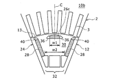
次に、図2を参照して、回転子鉄心12の磁極24の構成について説明する。なお、図2は回転子鉄心12の軸方向端面視状態で1つの磁極24を示す図であるが、回転子鉄心12を軸方向に垂直な断面の構成もこれと同様である。また、図2では固定子コイルの図示を省略している。さらに、図2において磁極24の周方向中心線が一点鎖線Cで示されている。
Next, the configuration of the
回転子鉄心12の外周部には、複数の磁極24が周方向に等間隔で設けられている。本実施形態では回転子鉄心12に8つの磁極24が設けられている例を示すので、各磁極24はシャフト14の回転軸位置を中心として周方向に45°ごとに磁極中央が位置するように設けられている。各磁極24は同様に構成されるので、以下においては1つの磁極の構成を記述するものとする。
A plurality of
磁極24は、周方向に関して磁極中央に埋設された第1永久磁石26と、第1永久磁石26の周方向両側に埋設され径方向内方または内周側へ向かって互いの間隔が狭まるように配置された一対の第2永久磁石28と、一対の第2永久磁石28の内周側端部間であって磁路領域30を挟んで第1永久磁石26と対向する位置に形成された磁束抑制穴32とを含む。
The
第1永久磁石26は、回転子鉄心12の外周面13近傍の内部に埋設されている。第1永久磁石26は、各2つの短辺側面および長辺側面を有する扁平長方形の軸方向端面(および軸方向に直交する断面)を有するとともに、回転子鉄心12と略同一の軸方向長さに形成されている。また、永久磁石26は、磁極中心線Cに対して線対称となる位置であって長辺側面が直交する姿勢で配置されている。ここで第1永久磁石26は、軸方向端面視上でW1の長手方向幅(すなわち長辺側面の長さ)を有している。
The first
第1永久磁石26は、回転子鉄心12内で軸方向に延伸して形成された磁石挿入穴34に挿入されている。磁石挿入穴34の周方向両側には、ポケット部36がそれぞれ連通して形成されている。ポケット部36を介して注入されるたとえば熱硬化性の樹脂が第1永久磁石26と磁石挿入穴34の内壁面との間に流入して硬化することにより、第1永久磁石26が磁石挿入穴34内に固定されている。
The first
ただし、磁石固定用の樹脂注入は何れか一方のポケット部36を介して行えばよく、他方のポケット部36は空隙のままとしてもよい。いずれにしてもポケット部36は、回転子鉄心12を構成する電磁鋼板よりも比透磁率が低い樹脂または空隙を内部に含むことから、第1永久磁石26の周方向両端における磁束の短絡を抑制する機能を有する。
However, the resin injection for fixing the magnet may be performed through one of the
第2永久磁石28もまた、第1永久磁石26と同様に、各2つの短辺側面および長辺側面を有する扁平長方形の軸方向端面(および軸方向に直交する断面)を有するとともに、回転子鉄心12と略同一の軸方向長さに形成されている。第2永久磁石28は、第1永久磁石26と同一の形状および大きさのものを用いてもよい。このように第1および第2永久磁石26,28を同一のものとすれば、永久磁石の製造および管理等に要するコストを低減できる利点がある。ただし、第1永久磁石26と第2永久磁石28とが異なる形状または大きさであってもよいことは勿論である。
Similarly to the first
磁極24において一対の第2永久磁石28は、それぞれ、回転子鉄心12内で軸方向に延伸して形成された磁石挿入穴38に挿入されて樹脂により固定されている。これにより、一対の第2永久磁石28は、回転子鉄心12の外周面13へ向かって互いに間隔が広がるように配置されている。逆にいえば、一対の第2永久磁石28は、上記のとおり内周側へ向かって互いの間隔が狭まるように配置されている。また、第2永久磁石28は、長手方向である長辺側面が径方向にほぼ沿って配置されているともいえる。さらに、一対の第2永久磁石28は、磁極中心線Cの周方向両側に線対称の関係に配置されている。そして、一対の第2永久磁石28の内周側端部間の間隔(すなわち磁極中心線Cと直交する方向の距離)W2は、上記第1永久磁石26の長手方向幅W1よりも広く設定されている。
換言すれば、第2永久磁石28は、磁極中心線Cに対して第1永久磁石26よりも外側に位置するように配置されている。詳細には、本実施形態によれば、第2永久磁石28の内周側端部が、第1永久磁石26の周方向端部に接するとともに上記磁極中心線Cと平行な接線に対して、周方向外側に位置している。すなわち、磁極中心線Cからの第2永久磁石28の内周側端部までの距離(W2の1/2)が、磁極中心線Cから第1永久磁石26の長手方向端部までの距離(W1の1/2)以上に設定されている。
In the
In other words, the second
上記磁石挿入穴38の外周側には、ポケット部40が磁石挿入穴38に連通して形成されている。このポケット部40は、第2永久磁石28の短辺側面に沿って軸方向に延伸して形成されている。ポケット部40は、電磁鋼板よりも比透磁率が低い空隙または樹脂を内部に含むことから、第2永久磁石28の外周側端部における磁束の短絡を抑制する機能を有する。第2永久磁石28を固定するための樹脂は、このポケット部40を介して注入されてもよい。
A
上記磁束抑制穴32は、一対の第2永久磁石28の内周側端部間であって内周寄り位置(図2中の下側)に形成されている。また、磁束抑制穴32は、磁路領域30を挟んで第1永久磁石26に対向して配置されている。磁束抑制穴32は、電磁鋼板よりも比透磁率が低い空隙を内部に含むことから、永久磁石26,28から発生した磁束の流れ、および、固定子2のティース3の内周先端から回転子鉄心12の磁極24の磁路領域30へ進入する磁束の流れを抑制する又は変化させる機能を有する。
The magnetic
本実施形態では磁束抑制穴32は、2つの第1の穴41,42と1つの第2の穴44によって構成されている。第1の穴41,42は、第2永久磁石28が挿入されている磁石挿入穴38の内周側端部に連通してそれぞれ形成される。第1の穴41,42は、磁極中心線Cの両側の対称位置に略三角形状に形成されている。また、第1の穴41,42は、第2永久磁石28の内周側の長辺方向端部における磁束の短絡を抑制する機能を有する。なお、第2永久磁石28を固定するための樹脂が第1の穴41,42を介して磁石挿入穴38に注入されてもよく、この場合、第1の穴も上記樹脂によって充填されてもよい。樹脂もまた、空隙と同様に低い比透磁率を有するので、上記のように磁束流を抑制する機能を果たすことができる。
In the present embodiment, the magnetic
第2の穴44は、第1の穴41,42の間に積層鋼板部分であるブリッジ部46をそれぞれ介して形成されている。また、第2の穴44は、磁極中心線Cが中央を通る対称形状の略矩形状に形成されている。そして、第2の穴44は、周方向に関して一対の第2永久磁石28間の中央に位置にして回転子鉄心12の外周面13に対向している。第2の穴44も同様に、電磁鋼板よりも比透磁率が低い空隙(または樹脂)を内部に含むことから、上記のように磁束流を抑制する機能を果たす。
The
なお、本実施形態では磁束抑制穴32が3つの穴41,42,44によって構成されるものとして説明するが、これに限定されるものではなく、形状および数において種々の変形が可能である。たとえば、磁極中心線Cに沿って1本のブリッジ部があってその両側に形成された2つの穴によって構成されてもよいし、または、ブリッジ部が存在しない1つの穴によって構成されてもよいし、あるいは、4つ以上の穴で構成されてもよい。また、磁束抑制穴32の全ての穴に、たとえば樹脂等の比透磁率が低い材料を充填してもよい。
In the present embodiment, the magnetic
磁極24において、第1永久磁石26、第2永久磁石28および磁束抑制穴32によって囲まれた積層鋼板部分が磁路領域30として形成されている。本実施形態では、第2永久磁石28の内周側端部間の間隔W2を第1永久磁石26の長手方向幅W1よりも広く設定していることで、第1永久磁石26および一対の第2永久磁石28によって囲まれた磁路領域30は略台形状をなしている。これにより、第2永久磁石28の内周側端部を互いに近接してV字型に配置した従来例の3枚永久磁石タイプの磁極での磁路領域に比べて各第2永久磁石28と第1永久磁石26との間の鉄心領域が広くなっている。また、略台形状の磁路領域30は、周方向両端側で外周側へ延伸して回転子鉄心12の外周面13へとつながっている。
In the
続いて、上記記構成からなる回転子10の磁極24における磁束の流れについて説明する。固定子2の固定子コイル5に電流が流れて回転子100が回転駆動されるとき、回転子10の磁極24には図3に示すような磁束の流れが形成される。
Next, the flow of magnetic flux in the
図3中の(A)は一方の第2永久磁石28から生じた磁石磁束が磁路領域30を通って外周側へ流れる様子を模式的に示し、図3中の(B)は固定子コイル5に流れる電流を直交座標系であるq軸d軸平面上でベクトル展開したときのq軸電流成分によって生じたq軸電流磁束が固定子2のティース3の内周先端から回転子鉄心12に流れ込んで磁極24内の磁路領域30を通る様子を模式的に示し、図3中の(C)は上記磁石磁束と上記q軸電流磁束とを合成した磁束の流れを模式的に示している。
3A schematically shows a state in which the magnetic flux generated from one second
図3(A)を参照すると、一方の第2永久磁石28から生じた磁石磁束は、磁路領域30を通って回転子鉄心12の外周面13へと向かう。また、図3(B)を参照すると、回転子鉄心12内の磁極24に流れ込んだq軸電流磁束についても同様に、磁気抵抗が小さい磁路領域30を略円弧状に通って外周面13側へと向かう。したがって、上記のように流れる磁石磁束とq軸電流磁束とが重なると、図3(C)に示すように、略台形状に形成される磁路領域30のうちハッチング部分で示す下流側領域または出口側領域48で合成磁束の密度が比較的高くはなるが、図9(C)に示すハッチング領域120と比較すると磁気飽和が懸念される領域を大幅に縮小することがきる。これにより、磁極24の磁石磁束が増加して磁石トルクの向上につながるとともに、q軸インダクタンスLqの増加によりリラクタンストルクも向上する。したがって、回転子10を用いた回転電機1において磁石トルクおよびリラクタンストルクの和である総トルクを効果的に向上させることができる。
Referring to FIG. 3A, the magnet magnetic flux generated from one second
また、本実施形態の回転子10では、磁極24の内周側に設けた磁束抑制穴32は磁束が通るのを抑制するため、第1永久磁石26からの磁束が磁極24の内周方向へ漏れるのを抑制することができるとともに、第2永久磁石28からの磁束が磁路領域30を介して磁極24の外周面13側へ効果的に流れることができる。これにより、磁極24の磁石磁束がさらに増加して磁石トルクの向上につながるとともに、d軸インダクタンスLdを低下させることができる。したがって、回転子10を用いた回転電機1において磁石トルクおよびリラクタンストルクをより効果的に向上させることができる。
Further, in the
そして、本実施形態の回転子10では、磁極24において磁極中央の第1永久磁石26とその周方向両側に一対の第2永久磁石28とを上記のように分散配置したことで、固定子コイル5に発生する逆起電圧を略正弦波状にすることができ、逆起電圧に含まれる特定次数の高調波成分によって生じる鉄損を低減することができる。
In the
なお、上記においては第1永久磁石28の内周側位置に磁束抑制穴32を設けた好適な実施形態について説明したが、このような磁束抑制穴は本発明における必須の構成要件ではないことから省略されてもよい。
In the above description, the preferred embodiment in which the magnetic
次に、図4〜7を参照して、上記実施形態の回転子10の変形例について説明する。
Next, with reference to FIGS. 4-7, the modification of the
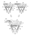
図4は、磁極24の中央にある第1永久磁石26が複数に分割されている例を示す。この例では、2つに分割された第1永久磁石26a,26bが磁極中心線Cを挟んだ対象位置で互いに近接して略V字状に外周側へ広がるように配置されている。2つの第1永久磁石26a,26bの間には、磁束の短絡を抑制するためのポケット部36がそれぞれ設けられている。この場合、2つの第1永久磁石26a,26bの外周側角部間の距離が第1永久磁石の長手方向幅W1に相当する。なお、第1永久磁石26a,26bの間にある2つの磁束抑制穴32は互いに連通して1つの穴として形成されてもよい。他の構成は、上記回転子10と同様であるため、同一または類似の構成要素に同一または類似の符合を付して説明を省略する。
FIG. 4 shows an example in which the first
図5は、磁極24の中央にある第1永久磁石28cの外周側面が略円弧状の湾曲面をなした例を示す。このように第1永久磁石の端面形状は矩形状でなくてもよく、このことは第2永久磁石についても同様である。他の構成は、上記回転子10と同様である。
FIG. 5 shows an example in which the outer peripheral side surface of the first permanent magnet 28 c at the center of the
図6は、一対の第2永久磁石が第1永久磁石26に向かって略V字状に配置されている例を示す。この例では、一対の第2永久磁石28は、それぞれ、互いに近接し且つ第1永久磁石26に向かって略V字状に広がるように配置された2つの永久磁石28a,28bにより構成される。この場合、一対の第2永久磁石28間で最も狭い間隔は、内周側にそれぞれ配置された2つの第2永久磁石28b,28bの内周側角部間の距離に相当する。他の構成は、上記回転子10と同様である。
FIG. 6 shows an example in which a pair of second permanent magnets are arranged in a substantially V shape toward the first
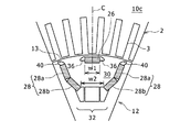
図7は、1つの磁極24内に複数のq軸磁路領域が形成されている例を示す。この例において磁極24は、一対の第2永久磁石の周方向両側に埋設され径方向内方へ向かって互いの間隔が狭まるように配置された一対の第3永久磁石50と、一対の第3永久磁石50の内周側端部間であって第1磁束抑制穴32に対向して形成される第2磁束抑制穴52とをさらに含む。そして、各一対の第2および第3永久磁石28,50ならびに第1および第2磁束抑制穴32,52によって第2磁路領域54が磁路領域30(第1磁路領域)の内周側に形成されている。この場合にも、一対の第3永久磁石50間の最も狭い間隔が、径方向と直交する方向における一対の第2永久磁石28の周方向外側縁部間の幅以上に設定されていることが好ましい。また、この場合には、磁極24の周方向幅の拡大を極力抑えるため、第1永久磁石26、一対の第2永久磁石28および磁束抑制穴32の形状、大きさ、配置等を上記回転子10の場合よりもコンパクトに設計するのが好ましい。他の構成は、上記回転子10と同様である。
FIG. 7 shows an example in which a plurality of q-axis magnetic path regions are formed in one
1 回転電機、2 固定子、3 ティース、4 スロット、5 固定子コイル、10,10a,10b,10c,10d 回転電機用回転子、11 軸穴、12 回転子鉄心、13 外周面、14 シャフト、15 フランジ部、16 エンドプレート、18 固定部材、20 かしめ部、22 押え部、24 磁極、26,26a,26b 第1永久磁石、28,28a,28b,28c 第2永久磁石、30 (第1)磁路領域、32,52 磁束抑制穴、34,38 磁石挿入穴、36,40 ポケット部、41,42 第1の穴、44 第2の穴、46 ブリッジ部、48 出口側領域、50 第3永久磁石、54 第2磁路領域、C 磁極中心線、Ld d軸インダクタンス、Lq q軸インダクタンス、W1 長手方向幅、W2 間隔。 DESCRIPTION OF SYMBOLS 1 Rotating electrical machine, 2 Stator, 3 teeth, 4 slots, 5 Stator coil, 10, 10a, 10b, 10c, 10d Rotating electrical machine rotor, 11 Shaft hole, 12 Rotor core, 13 Outer peripheral surface, 14 Shaft, 15 flange portion, 16 end plate, 18 fixing member, 20 caulking portion, 22 presser portion, 24 magnetic pole, 26, 26a, 26b first permanent magnet, 28, 28a, 28b, 28c second permanent magnet, 30 (first) Magnetic path region, 32, 52 Magnetic flux suppression hole, 34, 38 Magnet insertion hole, 36, 40 Pocket portion, 41, 42 First hole, 44 Second hole, 46 Bridge portion, 48 Outlet side region, 50 Third Permanent magnet, 54 second magnetic path region, C magnetic pole center line, Ld d-axis inductance, Lq q-axis inductance, W1 longitudinal width, W2 spacing.
Claims (6)
前記各磁極は、磁極中央に埋設された第1永久磁石と、前記第1永久磁石の周方向両側に埋設され径方向内方へ向かって互いの間隔が狭まるように配置された一対の第2永久磁石とを含み、前記第1永久磁石および前記一対の第2永久磁石に囲まれて形成される磁路領域において前記一対の第2永久磁石間の最も狭い間隔が前記第1永久磁石の長手方向幅よりも広く設定されている、
回転電機用回転子。 A rotor for a rotating electrical machine in which a plurality of magnetic poles are provided at intervals in the circumferential direction on an outer peripheral portion of a rotor core,
The magnetic poles include a first permanent magnet embedded in the center of the magnetic pole and a pair of second permanent magnets embedded on both sides in the circumferential direction of the first permanent magnet so as to be spaced from each other inward in the radial direction. A narrowest interval between the pair of second permanent magnets in a magnetic path region formed by being surrounded by the first permanent magnet and the pair of second permanent magnets. It is set wider than the direction width,
Rotor for rotating electrical machines.
前記各磁極は、前記一対の第2永久磁石の内周側端部間であって前記磁路領域を挟んで前記第1永久磁石に対向する位置に形成された磁束抑制穴をさらに含むことを特徴とする回転電機用回転子。 The rotor for a rotating electrical machine according to claim 1,
Each of the magnetic poles further includes a magnetic flux suppression hole formed between the inner peripheral side ends of the pair of second permanent magnets and facing the first permanent magnet with the magnetic path region interposed therebetween. A rotor for a rotating electrical machine.
前記磁束抑制穴は、前記一対の第2永久磁石がそれぞれ挿入されている第2磁石挿入穴の内周側端部に連通して形成される2つの第1の穴と、前記第1の穴の間にブリッジ部を介して形成されている第2の穴とにより構成され、前記第1および第2の穴の少なくとも一方は前記回転子鉄心を形成する磁性材料よりも比透磁率が低い空隙または樹脂を含むことを特徴とする回転電機用回転子。 The rotor for a rotating electrical machine according to claim 2,
The magnetic flux suppression holes include two first holes formed in communication with inner end portions of second magnet insertion holes into which the pair of second permanent magnets are inserted, and the first holes. And a second hole formed through a bridge portion, and at least one of the first and second holes has a lower relative permeability than the magnetic material forming the rotor core. Or the rotor for rotary electric machines characterized by including resin.
前記第1永久磁石は、互いに近接し且つ外周側へ向かって略V字状に広がるように配置された2つの永久磁石により構成されることを特徴とする回転電機用回転子。 The rotor for a rotating electrical machine according to claim 1 or 2,
The first permanent magnet is constituted by two permanent magnets arranged so as to be close to each other and spread in a substantially V shape toward the outer peripheral side.
前記一対の第2永久磁石は、それぞれ、互いに近接し且つ前記第1永久磁石に向かって略V字状に広がるように配置された2つの永久磁石により構成されることを特徴とする回転電機用回転子。 In the rotor for rotating electrical machines according to any one of claims 1 to 3,
The pair of second permanent magnets is composed of two permanent magnets arranged so as to be close to each other and spread in a substantially V shape toward the first permanent magnet. Rotor.
前記各磁極は、前記一対の第2永久磁石の内周側端部間であって前記第1永久磁石に対向する位置に形成された第1磁束抑制穴を含み、前記第1永久磁石、前記第2永久磁石および前記第1磁束抑制穴によって第1磁路領域が形成されており、
前記各磁極はさらに、前記一対の第2永久磁石の周方向両側に埋設され径方向内方へ向かって互いの間隔が狭まるように配置された一対の第3永久磁石と、前記一対の第3永久磁石の内周側端部間であって前記第1磁束抑制穴に対向して形成される第2磁束抑制穴とを含み、前記第2および第3永久磁石ならびに前記第1および第2磁束抑制穴によって第2磁路領域が前記第1磁路領域の内周側に形成されており、前記第2磁路領域において前記一対の第3永久磁石間の最も狭い間隔が、径方向と直交する方向における前記一対の第2永久磁石の周方向外側縁部間の幅以上に設定されていることを特徴とする回転電機用回転子。 In the rotor for rotary electric machines as described in any one of Claims 1-4,
Each of the magnetic poles includes a first magnetic flux suppression hole formed between the inner peripheral side ends of the pair of second permanent magnets and facing the first permanent magnet, and the first permanent magnet, A first magnetic path region is formed by the second permanent magnet and the first magnetic flux suppression hole,
Each of the magnetic poles further includes a pair of third permanent magnets that are embedded on both sides in the circumferential direction of the pair of second permanent magnets and arranged so that the distance from each other decreases radially inward, and the pair of third permanent magnets. A second magnetic flux suppression hole formed between the inner peripheral side ends of the permanent magnet and opposed to the first magnetic flux suppression hole, and the second and third permanent magnets and the first and second magnetic fluxes A second magnetic path region is formed on the inner peripheral side of the first magnetic path region by the suppression hole, and the narrowest distance between the pair of third permanent magnets in the second magnetic path region is orthogonal to the radial direction. The rotor for a rotating electrical machine is set to be equal to or larger than a width between circumferential edges of the pair of second permanent magnets in the direction in which the pair of second permanent magnets moves.
Priority Applications (6)
| Application Number | Priority Date | Filing Date | Title |
|---|---|---|---|
| JP2011021411A JP5643127B2 (en) | 2011-02-03 | 2011-02-03 | Rotating machine rotor |
| BR112013018579-1A BR112013018579B1 (en) | 2011-02-03 | 2012-02-02 | rotor for rotational electric machine |
| DE112012000667.4T DE112012000667T8 (en) | 2011-02-03 | 2012-02-02 | Rotor for electric machine |
| PCT/IB2012/000170 WO2012104715A1 (en) | 2011-02-03 | 2012-02-02 | Rotor for electric machine |
| CN201280007126.0A CN103339831B (en) | 2011-02-03 | 2012-02-02 | For the rotor of motor |
| US13/982,629 US9231445B2 (en) | 2011-02-03 | 2012-02-02 | Rotor for the electric machine |
Applications Claiming Priority (2)
| Application Number | Priority Date | Filing Date | Title |
|---|---|---|---|
| JP2011021411A JP5643127B2 (en) | 2011-02-03 | 2011-02-03 | Rotating machine rotor |
| PCT/IB2012/000170 WO2012104715A1 (en) | 2011-02-03 | 2012-02-02 | Rotor for electric machine |
Publications (2)
| Publication Number | Publication Date |
|---|---|
| JP2012161227A true JP2012161227A (en) | 2012-08-23 |
| JP5643127B2 JP5643127B2 (en) | 2014-12-17 |
Family
ID=45768255
Family Applications (1)
| Application Number | Title | Priority Date | Filing Date |
|---|---|---|---|
| JP2011021411A Active JP5643127B2 (en) | 2011-02-03 | 2011-02-03 | Rotating machine rotor |
Country Status (6)
| Country | Link |
|---|---|
| US (1) | US9231445B2 (en) |
| JP (1) | JP5643127B2 (en) |
| CN (1) | CN103339831B (en) |
| BR (1) | BR112013018579B1 (en) |
| DE (1) | DE112012000667T8 (en) |
| WO (1) | WO2012104715A1 (en) |
Cited By (12)
| Publication number | Priority date | Publication date | Assignee | Title |
|---|---|---|---|---|
| US8803394B2 (en) | 2011-02-03 | 2014-08-12 | Toyota Jidosha Kabushiki Kaisha | Rotor for rotary electric machine having a magnetic flux-restraining hole |
| WO2014155438A1 (en) * | 2013-03-29 | 2014-10-02 | 株式会社 東芝 | Permanent magnet reluctance dynamo-electric machine |
| US8890385B2 (en) | 2011-02-03 | 2014-11-18 | Toyota Jidosha Kabushiki Kaisha | Rotor for rotary electric machine |
| US8957561B2 (en) | 2011-02-03 | 2015-02-17 | Toyota Jidosha Kabushiki Kaisha | Rotor for rotary electric machine |
| JP2016082733A (en) * | 2014-10-17 | 2016-05-16 | 株式会社明電舎 | Magnet embedded motor |
| JP2018082540A (en) * | 2016-11-15 | 2018-05-24 | トヨタ自動車株式会社 | Rotary electric machine |
| CN109510347A (en) * | 2017-09-15 | 2019-03-22 | 丰田自动车株式会社 | Rotating electric machine |
| JP2020137139A (en) * | 2019-02-12 | 2020-08-31 | トヨタ自動車株式会社 | Rotary electric machine |
| CN113224876A (en) * | 2020-02-05 | 2021-08-06 | 本田技研工业株式会社 | Rotor of rotating electric machine |
| WO2021250921A1 (en) * | 2020-06-08 | 2021-12-16 | アイシン・エィ・ダブリュ株式会社 | Rotor for dynamo-electric machine |
| WO2022097322A1 (en) * | 2020-11-09 | 2022-05-12 | 日本電産株式会社 | Rotary electrical machine |
| JP7390203B2 (en) | 2020-02-05 | 2023-12-01 | 本田技研工業株式会社 | Rotor and arc magnet manufacturing method for rotating electric machine |
Families Citing this family (56)
| Publication number | Priority date | Publication date | Assignee | Title |
|---|---|---|---|---|
| WO2012014260A1 (en) * | 2010-07-30 | 2012-02-02 | 株式会社 日立製作所 | Rotating electrical machine, and electric vehicle using same |
| KR101429848B1 (en) * | 2013-02-13 | 2014-08-12 | 한승주 | Air Expander driven by Rotating Magnetic Field |
| US10511198B2 (en) * | 2013-05-01 | 2019-12-17 | Hitachi Automotive Systems, Ltd. | Rotary electrical machine, and rotor for rotary electrical machine |
| US10135307B2 (en) * | 2014-04-28 | 2018-11-20 | Mitsubishi Electric Corporation | Rotor, permanent-magnet-embedded motor, and compressor |
| DE102014214469A1 (en) * | 2014-07-24 | 2016-01-28 | Siemens Aktiengesellschaft | Rotor for an electric machine |
| CN106030988B (en) * | 2014-08-11 | 2018-08-31 | 富士电机株式会社 | Electric rotating machine |
| WO2016024324A1 (en) * | 2014-08-11 | 2016-02-18 | 富士電機株式会社 | Dynamo-electric machine |
| JP6137121B2 (en) * | 2014-11-07 | 2017-05-31 | トヨタ自動車株式会社 | Rotor structure and rotor manufacturing method |
| JP6390506B2 (en) | 2015-04-28 | 2018-09-19 | 株式会社デンソー | Rotating electrical machine rotor |
| GB2545627B (en) * | 2015-10-16 | 2021-04-21 | Yasa Ltd | Axial flux machine arrangement |
| JP6279685B2 (en) * | 2015-10-26 | 2018-02-14 | 株式会社三井ハイテック | Manufacturing method of laminated iron core |
| JP6894663B2 (en) * | 2015-10-29 | 2021-06-30 | 株式会社富士通ゼネラル | Rotor and permanent magnet motor |
| CN105811684A (en) * | 2016-05-11 | 2016-07-27 | 山东理工大学 | Production method of radial and built-in tangential permanent magnetic steel drive motor rotor for electric automobile |
| CN105811704A (en) * | 2016-05-11 | 2016-07-27 | 山东理工大学 | Composite permanent-magnet invisible magnetic pole and brushless electromagnetic hybrid excitation driving motor |
| CN105790471A (en) * | 2016-05-11 | 2016-07-20 | 山东理工大学 | Permanent magnet generator and vacuum pump integrating device |
| DE102016209711A1 (en) * | 2016-06-02 | 2018-01-04 | Volkswagen Aktiengesellschaft | rotor core |
| GB2551537A (en) * | 2016-06-21 | 2017-12-27 | Jaguar Land Rover Ltd | Electrical machine |
| EP3352331A1 (en) * | 2017-01-19 | 2018-07-25 | Siemens Aktiengesellschaft | Rotor sheet for a permanently excited electric motor and rotor |
| DE102017103619A1 (en) * | 2017-02-22 | 2018-08-23 | Ebm-Papst St. Georgen Gmbh & Co. Kg | Electric motor, inner rotor and rotor plate |
| CN110326191B (en) * | 2017-02-28 | 2022-02-08 | 日立安斯泰莫株式会社 | Rotor of rotating electrical machine and rotating electrical machine provided with same |
| CN110383637A (en) * | 2017-03-03 | 2019-10-25 | 通用电气再生能源技术公司 | Salient-pole machine |
| US10608487B2 (en) * | 2017-03-07 | 2020-03-31 | Ford Global Technologies, Llc | Electric machine rotor |
| US10355537B2 (en) | 2017-03-27 | 2019-07-16 | Ford Global Technologies, Llc | Method for adjusting magnetic permeability of electrical steel |
| FR3064837B1 (en) * | 2017-04-03 | 2020-01-17 | Moving Magnet Technologies | ROTOR FOR ELECTRIC MACHINE WITH INTERNAL PERMANENT MAGNETS |
| EP3386075B1 (en) * | 2017-04-06 | 2020-07-29 | LG Electronics Inc. | Electric motor with permament magnet and compressor having the same |
| JP6821022B2 (en) * | 2017-06-19 | 2021-01-27 | 日産自動車株式会社 | Rotor of rotating electric machine |
| JP6503016B2 (en) * | 2017-06-21 | 2019-04-17 | ファナック株式会社 | Rotor and rotating electric machine |
| EP3675328A1 (en) * | 2017-08-22 | 2020-07-01 | Kabushiki Kaisha Toshiba | Rotary electric device |
| CN108566005B (en) | 2018-03-16 | 2020-10-30 | 珠海格力节能环保制冷技术研究中心有限公司 | Rotor structure, permanent magnet auxiliary synchronous reluctance motor and electric automobile |
| CN108321954B (en) * | 2018-03-16 | 2020-10-23 | 珠海格力节能环保制冷技术研究中心有限公司 | Rotor structure, permanent magnet auxiliary synchronous reluctance motor and electric automobile |
| CN108429375B (en) * | 2018-05-08 | 2020-06-16 | 珠海格力电器股份有限公司 | Rotor structure, permanent magnet auxiliary synchronous reluctance motor and electric automobile |
| CN108711977A (en) * | 2018-06-25 | 2018-10-26 | 苏州汇川联合动力系统有限公司 | Rotor and magneto |
| CN110875657A (en) * | 2018-08-31 | 2020-03-10 | 比亚迪股份有限公司 | Motor rotor, motor and electric automobile |
| DE102018215864A1 (en) * | 2018-09-18 | 2020-03-19 | Robert Bosch Gmbh | Rotor of an electric motor and electric motor |
| JPWO2020067348A1 (en) * | 2018-09-28 | 2021-08-30 | 本田技研工業株式会社 | Rotating electric rotor |
| JP2020078200A (en) * | 2018-11-08 | 2020-05-21 | 本田技研工業株式会社 | Rotary electric machine rotor |
| DE102019102540A1 (en) * | 2019-02-01 | 2020-08-06 | Bayerische Motoren Werke Aktiengesellschaft | Embedded magnet arrangement for permanently excited electrical machines |
| CN110138119A (en) * | 2019-03-11 | 2019-08-16 | 浙江龙芯电驱动科技有限公司 | A kind of permanent-magnetic synchronous motor rotor of the tangential magnetic structure of high-performance |
| CN109995164A (en) * | 2019-04-23 | 2019-07-09 | 山东理工大学 | Asymmetric magnetic pole type permanent magnetism for electric vehicle and pawl pole electrical excitation driving motor |
| TWI711246B (en) * | 2019-06-03 | 2020-11-21 | 威剛科技股份有限公司 | Axial rotor of axial gap type electrical rotation machine |
| WO2021000184A1 (en) * | 2019-06-30 | 2021-01-07 | 瑞声声学科技(深圳)有限公司 | Vibration motor |
| US11289985B2 (en) * | 2019-08-09 | 2022-03-29 | Hamilton Sundstrand Corporation | Dual stator machine with a rotor magnet set configured to minimize flux leakage |
| US11264850B2 (en) * | 2019-09-05 | 2022-03-01 | Nidec Motor Corporation | Laminated rotor having deflecting magnet retaining prongs and support posts for the prongs |
| JP7131516B2 (en) * | 2019-09-18 | 2022-09-06 | トヨタ自動車株式会社 | Embedded magnet motor and manufacturing method thereof |
| KR20210089500A (en) * | 2020-01-08 | 2021-07-16 | 엘지전자 주식회사 | Stator ofelectric rotation machine |
| JP2021122163A (en) * | 2020-01-31 | 2021-08-26 | 日立金属株式会社 | Rotary electric machine |
| DE102020115286A1 (en) * | 2020-06-09 | 2021-12-09 | Schaeffler Technologies AG & Co. KG | Electric motor with pockets for holding magnets |
| JP7415871B2 (en) * | 2020-10-22 | 2024-01-17 | トヨタ自動車株式会社 | rotating electric machine |
| DE102020214035A1 (en) | 2020-11-09 | 2022-05-12 | Robert Bosch Gesellschaft mit beschränkter Haftung | Rotor of an electrical machine with a multi-layer permanent magnet arrangement |
| US11791678B2 (en) * | 2021-02-25 | 2023-10-17 | National Cheng Kung University | Motor and rotor structure thereof |
| CN112865368A (en) * | 2021-02-26 | 2021-05-28 | 合肥巨一动力系统有限公司 | Rotor punching sheet structure |
| CN112968560A (en) * | 2021-03-26 | 2021-06-15 | 合肥巨一动力系统有限公司 | Rotary motor punching sheet and rotor |
| JP7090773B1 (en) * | 2021-04-01 | 2022-06-24 | 三菱電機株式会社 | Rotating electric machine |
| US11641151B2 (en) * | 2021-05-11 | 2023-05-02 | Aac Microtech (Changzhou) Co., Ltd. | Linear vibration motor with elastic members with brackets, foams and damping glue |
| CN113644768B (en) * | 2021-08-13 | 2022-12-06 | 北京中科三环高技术股份有限公司 | Motor rotor and IPM motor |
| DE102021126750B4 (en) | 2021-10-15 | 2023-06-22 | Schaeffler Technologies AG & Co. KG | Process for manufacturing a rotor for an electrical machine |
Citations (2)
| Publication number | Priority date | Publication date | Assignee | Title |
|---|---|---|---|---|
| JP2006311772A (en) * | 2005-05-02 | 2006-11-09 | Nissan Motor Co Ltd | Dynamo-electric motor |
| JP2007274798A (en) * | 2006-03-31 | 2007-10-18 | Hitachi Ltd | Permanent-magnet rotating electric machine |
Family Cites Families (18)
| Publication number | Priority date | Publication date | Assignee | Title |
|---|---|---|---|---|
| US6087751A (en) * | 1997-07-01 | 2000-07-11 | Kabushiki Kaisha Toshiba | Reluctance type rotating machine with permanent magnets |
| JP2002078259A (en) * | 2000-08-31 | 2002-03-15 | Yamaha Motor Co Ltd | Permanent magnet rotor |
| JP2002354730A (en) * | 2001-05-25 | 2002-12-06 | Hitachi Ltd | Permanent magnet electric rotating machine |
| US7518278B2 (en) | 2004-05-18 | 2009-04-14 | Ut-Battelle, Llc | High strength undiffused brushless machine and method |
| JP2006314152A (en) * | 2005-05-06 | 2006-11-16 | Nissan Motor Co Ltd | Permanent-magnet motor |
| US7436095B2 (en) * | 2005-10-31 | 2008-10-14 | Caterpillar Inc. | Rotary electric machine |
| CN2894036Y (en) * | 2006-02-28 | 2007-04-25 | 曹小元 | Economic self-starting permanent magnetic synchronous motor |
| JP2008306849A (en) | 2007-06-07 | 2008-12-18 | Toyota Motor Corp | Rotating electrical machine |
| JP4492681B2 (en) * | 2007-11-16 | 2010-06-30 | 株式会社デンソー | Synchronous machine |
| JP5253098B2 (en) * | 2008-11-07 | 2013-07-31 | トヨタ自動車株式会社 | Rotating electric machine |
| JP4821902B2 (en) * | 2009-09-30 | 2011-11-24 | ダイキン工業株式会社 | Motor and motor drive system including the same |
| JP5479978B2 (en) * | 2010-03-30 | 2014-04-23 | アイシン・エィ・ダブリュ株式会社 | Rotating electric machine |
| WO2012008295A1 (en) | 2010-07-14 | 2012-01-19 | 株式会社 豊田自動織機 | Rotating element with embedded permanent magnet and rotating electrical machine |
| JP5480176B2 (en) | 2011-02-03 | 2014-04-23 | アイシン・エィ・ダブリュ株式会社 | Rotating machine rotor |
| JP5382012B2 (en) | 2011-02-03 | 2014-01-08 | トヨタ自動車株式会社 | Rotor for rotating electrical machine and method for manufacturing the same |
| JP5328821B2 (en) | 2011-02-03 | 2013-10-30 | トヨタ自動車株式会社 | Rotating machine rotor |
| JP5353917B2 (en) | 2011-02-03 | 2013-11-27 | トヨタ自動車株式会社 | Rotating machine rotor |
| JP2012161226A (en) | 2011-02-03 | 2012-08-23 | Toyota Motor Corp | Rotor for rotary electric machine |
-
2011
- 2011-02-03 JP JP2011021411A patent/JP5643127B2/en active Active
-
2012
- 2012-02-02 BR BR112013018579-1A patent/BR112013018579B1/en active IP Right Grant
- 2012-02-02 WO PCT/IB2012/000170 patent/WO2012104715A1/en active Application Filing
- 2012-02-02 CN CN201280007126.0A patent/CN103339831B/en active Active
- 2012-02-02 US US13/982,629 patent/US9231445B2/en active Active
- 2012-02-02 DE DE112012000667.4T patent/DE112012000667T8/en active Active
Patent Citations (2)
| Publication number | Priority date | Publication date | Assignee | Title |
|---|---|---|---|---|
| JP2006311772A (en) * | 2005-05-02 | 2006-11-09 | Nissan Motor Co Ltd | Dynamo-electric motor |
| JP2007274798A (en) * | 2006-03-31 | 2007-10-18 | Hitachi Ltd | Permanent-magnet rotating electric machine |
Cited By (16)
| Publication number | Priority date | Publication date | Assignee | Title |
|---|---|---|---|---|
| US8803394B2 (en) | 2011-02-03 | 2014-08-12 | Toyota Jidosha Kabushiki Kaisha | Rotor for rotary electric machine having a magnetic flux-restraining hole |
| US8890385B2 (en) | 2011-02-03 | 2014-11-18 | Toyota Jidosha Kabushiki Kaisha | Rotor for rotary electric machine |
| US8957561B2 (en) | 2011-02-03 | 2015-02-17 | Toyota Jidosha Kabushiki Kaisha | Rotor for rotary electric machine |
| WO2014155438A1 (en) * | 2013-03-29 | 2014-10-02 | 株式会社 東芝 | Permanent magnet reluctance dynamo-electric machine |
| JP2014200150A (en) * | 2013-03-29 | 2014-10-23 | 株式会社東芝 | Permanent magnet type reluctance rotary electric machine |
| JP2016082733A (en) * | 2014-10-17 | 2016-05-16 | 株式会社明電舎 | Magnet embedded motor |
| JP2018082540A (en) * | 2016-11-15 | 2018-05-24 | トヨタ自動車株式会社 | Rotary electric machine |
| CN109510347A (en) * | 2017-09-15 | 2019-03-22 | 丰田自动车株式会社 | Rotating electric machine |
| JP2020137139A (en) * | 2019-02-12 | 2020-08-31 | トヨタ自動車株式会社 | Rotary electric machine |
| JP7107243B2 (en) | 2019-02-12 | 2022-07-27 | トヨタ自動車株式会社 | Rotating electric machine |
| CN113224876A (en) * | 2020-02-05 | 2021-08-06 | 本田技研工业株式会社 | Rotor of rotating electric machine |
| CN113224876B (en) * | 2020-02-05 | 2023-09-22 | 本田技研工业株式会社 | Rotor of rotating electrical machine |
| JP7379196B2 (en) | 2020-02-05 | 2023-11-14 | 本田技研工業株式会社 | Rotating electric machine rotor |
| JP7390203B2 (en) | 2020-02-05 | 2023-12-01 | 本田技研工業株式会社 | Rotor and arc magnet manufacturing method for rotating electric machine |
| WO2021250921A1 (en) * | 2020-06-08 | 2021-12-16 | アイシン・エィ・ダブリュ株式会社 | Rotor for dynamo-electric machine |
| WO2022097322A1 (en) * | 2020-11-09 | 2022-05-12 | 日本電産株式会社 | Rotary electrical machine |
Also Published As
| Publication number | Publication date |
|---|---|
| BR112013018579A2 (en) | 2016-09-27 |
| WO2012104715A8 (en) | 2013-03-07 |
| US9231445B2 (en) | 2016-01-05 |
| JP5643127B2 (en) | 2014-12-17 |
| WO2012104715A1 (en) | 2012-08-09 |
| CN103339831A (en) | 2013-10-02 |
| DE112012000667T5 (en) | 2013-10-31 |
| DE112012000667T8 (en) | 2014-03-06 |
| BR112013018579B1 (en) | 2021-02-23 |
| US20130307363A1 (en) | 2013-11-21 |
| CN103339831B (en) | 2015-09-02 |
Similar Documents
| Publication | Publication Date | Title |
|---|---|---|
| JP5643127B2 (en) | Rotating machine rotor | |
| JP5353917B2 (en) | Rotating machine rotor | |
| JP5328821B2 (en) | Rotating machine rotor | |
| JP5480176B2 (en) | Rotating machine rotor | |
| JP5709907B2 (en) | Permanent magnet embedded rotary electric machine for vehicles | |
| CN112838693B (en) | Rotary electric machine | |
| JP5962632B2 (en) | Rotor for rotating electrical machine and method for manufacturing the same | |
| WO2013179375A1 (en) | Composite torque rotating electric machine | |
| CN108352744B (en) | Permanent magnet motor | |
| JP2012161226A (en) | Rotor for rotary electric machine | |
| WO2013128979A1 (en) | Hybrid excitation-type rotating machine | |
| JP6748852B2 (en) | Brushless motor | |
| JP2016220514A (en) | Rotary electric machine | |
| WO2014162804A1 (en) | Rotating electrical machine with embedded permanent magnet | |
| JP6019876B2 (en) | Rotating electric machine | |
| JP2018011466A (en) | Permanent-magnet embedded synchronous machine | |
| JP2013236418A (en) | Rotary electric machine | |
| JP4687687B2 (en) | Axial gap type rotating electric machine and field element | |
| JP2019161828A (en) | Rotary electric machine | |
| JP2013176267A (en) | Rotor | |
| JP2005210828A (en) | Rotating electric machine and rotor therefor | |
| JP2015006110A (en) | Motor device | |
| JP2014050253A (en) | Permanent magnet rotary electric machine rotor, and permanent magnet rotary electric machine | |
| JP2009038897A (en) | Axial gap motor | |
| JP6338139B2 (en) | Permanent magnet embedded motor |
Legal Events
| Date | Code | Title | Description |
|---|---|---|---|
| A621 | Written request for application examination |
Free format text: JAPANESE INTERMEDIATE CODE: A621 Effective date: 20130328 |
|
| A977 | Report on retrieval |
Free format text: JAPANESE INTERMEDIATE CODE: A971007 Effective date: 20140131 |
|
| A131 | Notification of reasons for refusal |
Free format text: JAPANESE INTERMEDIATE CODE: A131 Effective date: 20140218 |
|
| A521 | Request for written amendment filed |
Free format text: JAPANESE INTERMEDIATE CODE: A523 Effective date: 20140404 |
|
| TRDD | Decision of grant or rejection written | ||
| A01 | Written decision to grant a patent or to grant a registration (utility model) |
Free format text: JAPANESE INTERMEDIATE CODE: A01 Effective date: 20141014 |
|
| A61 | First payment of annual fees (during grant procedure) |
Free format text: JAPANESE INTERMEDIATE CODE: A61 Effective date: 20141030 |
|
| R151 | Written notification of patent or utility model registration |
Ref document number: 5643127 Country of ref document: JP Free format text: JAPANESE INTERMEDIATE CODE: R151 |
|
| R250 | Receipt of annual fees |
Free format text: JAPANESE INTERMEDIATE CODE: R250 |
|
| R250 | Receipt of annual fees |
Free format text: JAPANESE INTERMEDIATE CODE: R250 |
|
| R250 | Receipt of annual fees |
Free format text: JAPANESE INTERMEDIATE CODE: R250 |
|
| R250 | Receipt of annual fees |
Free format text: JAPANESE INTERMEDIATE CODE: R250 |
|
| R250 | Receipt of annual fees |
Free format text: JAPANESE INTERMEDIATE CODE: R250 |
|
| R250 | Receipt of annual fees |
Free format text: JAPANESE INTERMEDIATE CODE: R250 |
|
| R250 | Receipt of annual fees |
Free format text: JAPANESE INTERMEDIATE CODE: R250 |