JP6965032B2 - Pachinko machine - Google Patents

Pachinko machine Download PDF

Info

Publication number
JP6965032B2
JP6965032B2 JP2017119423A JP2017119423A JP6965032B2 JP 6965032 B2 JP6965032 B2 JP 6965032B2 JP 2017119423 A JP2017119423 A JP 2017119423A JP 2017119423 A JP2017119423 A JP 2017119423A JP 6965032 B2 JP6965032 B2 JP 6965032B2
Authority
JP
Japan
Prior art keywords
effect
display
image
symbol
game
Prior art date
Legal status (The legal status is an assumption and is not a legal conclusion. Google has not performed a legal analysis and makes no representation as to the accuracy of the status listed.)
Active
Application number
JP2017119423A
Other languages
Japanese (ja)
Other versions
JP2019000514A (en
JP2019000514A5 (en
Inventor
敏男 小倉
Current Assignee (The listed assignees may be inaccurate. Google has not performed a legal analysis and makes no representation or warranty as to the accuracy of the list.)
Sankyo Co Ltd
Original Assignee
Sankyo Co Ltd
Priority date (The priority date is an assumption and is not a legal conclusion. Google has not performed a legal analysis and makes no representation as to the accuracy of the date listed.)
Filing date
Publication date
Application filed by Sankyo Co Ltd filed Critical Sankyo Co Ltd
Priority to JP2017119423A priority Critical patent/JP6965032B2/en
Publication of JP2019000514A publication Critical patent/JP2019000514A/en
Publication of JP2019000514A5 publication Critical patent/JP2019000514A5/ja
Application granted granted Critical
Publication of JP6965032B2 publication Critical patent/JP6965032B2/en
Active legal-status Critical Current
Anticipated expiration legal-status Critical

Links

Images

Description

本発明は、遊技が可能な遊技機に関する。 The present invention relates to a gaming machine capable of playing a game.

従来の遊技機は、プッシュセンサ(検出手段)によって遊技者によるプッシュボタンの操作(遊技者の動作)を検出したことに基づいて特定演出(動作演出)を実行可能であるとともに、演出表示装置(演出表示手段)において、遊技者に対してプッシュボタンの操作を促す操作指示画像(動作促進表示)としてのプッシュボタンの画像と、該操作指示画像よりも前に、操作指示画像が表示されることを示唆する動作示唆表示としても複数のプッシュボタンの画像を表示可能なものがある(例えば、特許文献1参照)。 The conventional game machine can execute a specific effect (motion effect) based on the detection of the push button operation (movement of the player) by the player by the push sensor (detection means), and also can execute the effect display device (effect display device). In the effect display means), the image of the push button as the operation instruction image (operation promotion display) for urging the player to operate the push button and the operation instruction image are displayed before the operation instruction image. There is also an operation suggestion display that can display images of a plurality of push buttons (see, for example, Patent Document 1).

特開2015−167701号公報Japanese Unexamined Patent Publication No. 2015-167701

しかしながら、特許文献1にあっては、演出表示装置に動作示唆表示を表示することによって、動作促進表示が表示されることを示唆するのみであるため、遊技興趣を向上できないという問題がある。 However, in Patent Document 1, there is a problem that the game entertainment cannot be improved because it only suggests that the operation promotion display is displayed by displaying the operation suggestion display on the effect display device.

本発明は、このような問題点に着目してなされたもので、遊技興趣を向上できる遊技機を提供することを目的とする。 The present invention has been made by paying attention to such a problem, and an object of the present invention is to provide a gaming machine capable of improving the enjoyment of gaming.

前記課題を解決するために、手段Aに記載の遊技機は、
遊技者にとって有利な有利状態に制御可能な遊技機であって、
演出表示手段と、
遊技者の動作を検出可能な検出手段と、
遊技に関する演出の実行を制御する演出制御手段と、
を備え、
前記演出制御手段は、
遊技者に対する動作促進表示を前記演出表示手段に表示し遊技者の動作を検出したことに基づいて演出表示を行う動作演出と、前記動作演出が実行されることを示唆する動作示唆表示を前記演出表示手段に表示する動作示唆演出とを実行可能であり、
演出表示の種類の異なる複数の前記動作演出を実行可能であり、
前記動作示唆演出の実行中に、前記動作演出の演出表示の種類を示唆する複数の演出種類示唆表示を前記演出表示手段に表示可能であり、
前記演出表示手段に表示される前記動作示唆演出の数と前記動作種類示唆表示の数とが同数であり、
特定の動作示唆表示を表示した後に、該特定の動作示唆表示に対応する動作促進表示を表示して前記動作演出を実行し、
前記特定の動作示唆表示が表示されている間に、前記特定の動作示唆表示に対応しない前記動作演出を実行可能であり、
前記特定の動作示唆表示に対応しない前記動作演出は、前記有利状態に制御される期待度を示唆する演出表示を行う、
ことを特徴としている。
前記課題を解決するために、手段1に記載の遊技機は、
遊技が可能な遊技機(例えば、パチンコ遊技機1)であって、
演出表示手段(例えば、演出表示装置5)と、
遊技者の動作を検出可能な検出手段(例えば、プッシュボタン31Bやスティックコントローラ31A)と、
遊技に関する演出の実行を制御する演出制御手段(例えば、演出制御用CPU120が演出図柄変動開始処理や演出図柄変動中処理を実行する部分)と、
を備え、
前記演出制御手段は、
遊技者に対する動作促進表示を前記演出表示手段に表示し遊技者の動作を検出したことに基づいて演出表示を行う動作演出(例えば、第1操作後演出)と、前記動作演出が実行されることを示唆する動作示唆表示(例えば、操作示唆画像としてのプッシュボタン31Bの画像210)を前記演出表示手段に表示する動作示唆演出(例えば、演出表示装置5の表示領域に操作示唆画像としての2つのプッシュボタン31Bの画像210を表示する部分)とを実行可能であり、
演出表示の種類の異なる複数の前記動作演出を実行可能であり(例えば、第1操作後演出として、味方キャラクタが敵キャラクタに勝利する演出と、味方キャラクタが敵キャラクタに敗北する演出と、味方キャラクタが敵キャラクタと引き分ける演出と、を実行可能な部分)、
前記動作示唆演出の実行中に、前記動作演出の演出表示の種類を示唆する複数の演出種類示唆表示を前記演出表示手段に表示可能である(例えば、図28に示すように、味方キャラクタが敵キャラクタに勝利することを示唆する「勝利!」のメッセージ画像220や、味方キャラクタが敵キャラクタと引き分けることを示唆する「引分!」のメッセージ画像220を表示可能な部分)
ことを特徴としている。
この特徴によれば、動作促進表示が表示されるよりも前に、動作示唆表示とともに演出種類示唆表示が表示されて、動作演出の演出表示の種類が事前に示唆されるため、動作演出にて表示される演出表示の種類がどのようになるかに遊技者に注目させることができ、遊技興趣を向上できる。
In order to solve the above-mentioned problems, the gaming machine according to the means A is
A gaming machine that can be controlled to an advantageous state that is advantageous to the player.
Production display means and
A detection means that can detect the movement of the player,
Production control means that controls the execution of production related to the game,
With
The effect control means
The effect of displaying the motion promotion display for the player on the effect display means and displaying the effect based on the detection of the player's motion, and the effect suggestion display suggesting that the motion effect is executed. It is possible to execute the action suggestion effect to be displayed on the display means.
It is possible to execute a plurality of the above-mentioned operation effects having different types of effect displays.
During the execution of the motion suggestion effect, a plurality of effect type suggestion displays suggesting the type of effect display of the motion effect can be displayed on the effect display means.
The number of the motion suggestion effects displayed on the effect display means and the number of the motion type suggestion displays are the same.
After displaying the specific motion suggestion display, the motion promotion display corresponding to the specific motion suggestion display is displayed to execute the motion effect.
While the specific motion suggestion display is displayed, it is possible to execute the motion effect that does not correspond to the specific motion suggestion display.
The motion effect that does not correspond to the specific motion suggestion display performs an effect display that suggests the degree of expectation controlled in the advantageous state.
It is characterized by that.
In order to solve the above-mentioned problems, the gaming machine according to the means 1 is
A gaming machine capable of playing (for example, pachinko gaming machine 1).
The effect display means (for example, effect display device 5) and
Detection means (for example, push button 31B or stick controller 31A) capable of detecting the movement of the player, and
The effect control means (for example, the portion where the effect control CPU 120 executes the effect symbol change start process and the effect symbol change process) and the effect control means for controlling the execution of the effect related to the game.
With
The effect control means
An operation effect (for example, an effect after the first operation) in which an action promotion display for the player is displayed on the effect display means and the effect is displayed based on the detection of the player's operation, and the operation effect is executed. (For example, the image 210 of the push button 31B as the operation suggestion image) for displaying the action suggestion display (for example, the image 210 of the push button 31B as the operation suggestion image) on the effect display means. The part of the push button 31B that displays the image 210) can be executed.
It is possible to execute a plurality of the above-mentioned motion effects having different types of effect displays (for example, as an effect after the first operation, an effect in which a ally character wins an enemy character, an effect in which a ally character is defeated by an enemy character, and an ally character The part where you can perform the effect of drawing with the enemy character),
During the execution of the motion suggestion effect, a plurality of effect type suggestion displays suggesting the type of effect display of the motion effect can be displayed on the effect display means (for example, as shown in FIG. 28, a ally character is an enemy. A part that can display a "victory!" Message image 220 that suggests winning the character and a "draw!" Message image 220 that suggests that the ally character draws with the enemy character)
It is characterized by that.
According to this feature, the effect type suggestion display is displayed together with the motion suggestion display before the motion promotion display is displayed, and the type of the effect display of the motion effect is suggested in advance. It is possible to draw attention to the player to see what kind of effect display will be displayed, and it is possible to improve the interest of the game.

段2の遊技機は、手段1に記載の遊技機であって、
前記演出制御手段は、
特定の動作示唆表示を表示した後に、該特定の動作示唆表示に対応する動作促進表示を表示して前記動作演出を実行し(例えば、操作示唆画像としての2つのプッシュボタン31Bの画像210を演出表示装置5の表示領域の中央に表示した後、該表示領域の中央に操作促進画像としてのプッシュボタン31Bの画像230を表示して第1操作後演出を実行する部分)、
前記特定の動作示唆表示が表示されている間に、前記特定の動作示唆表示に対応しない前記動作演出を実行可能である(例えば、変形例2として図37に示すように、演出表示装置5の表示領域の右端部においてボタン操作演出を実行する部分)
ことを特徴としている。
この特徴によれば、遊技の興趣を向上させることができる。
Gaming machine hand stage 2, a gaming machine according to the means 1,
The effect control means
After displaying the specific motion suggestion display, the motion promotion display corresponding to the specific motion suggestion display is displayed and the motion effect is executed (for example, the image 210 of the two push buttons 31B as the operation suggestion image is produced. After displaying in the center of the display area of the display device 5, the image 230 of the push button 31B as the operation promotion image is displayed in the center of the display area to execute the first post-operation effect).
While the specific motion suggestion display is displayed, the motion effect that does not correspond to the specific motion suggestion display can be executed (for example, as shown in FIG. 37 as a modification 2, the effect display device 5 The part that executes the button operation effect at the right end of the display area)
It is characterized by that.
According to this feature, the interest of the game can be improved.

段3の遊技機は、手段1または手段2に記載の遊技機であって、
前記演出種類示唆表示の数と前記動作示唆表示の数は同数である(例えば、図28(E)に示すように、演出表示装置5の表示領域に操作示唆画像としての2つのプッシュボタン31Bの画像210と、結果示唆画像としての2つのメッセージ画像220を表示する部分)
ことを特徴としている。
この特徴によれば、演出種類示唆表示の数と動作示唆表示の数とが異なる場合と比較して、演出種類示唆表示と動作示唆表示とを遊技者が識別し易くできるので、遊技興趣を向上できる。
Gaming machine Hand stage 3, a gaming machine according to the means 1 or means 2,
The number of the effect type suggestion display and the number of the operation suggestion display are the same (for example, as shown in FIG. 28E), two push buttons 31B as operation suggestion images are displayed in the display area of the effect display device 5. Image 210 and two message images 220 as result suggestion images are displayed)
It is characterized by that.
According to this feature, the player can easily distinguish between the effect type suggestion display and the action suggestion display as compared with the case where the number of effect type suggestion displays and the number of action suggestion displays are different. can.

段4の遊技機は、手段1〜手段3のいずれかに記載の遊技機であって、
前記演出制御手段は、前記動作促進表示が表示されるまでに、前記演出種類示唆表示を終了する(例えば、図29(G)に示すように、操作促進画像が表示されるタイミングで結果示唆画像としての2つのメッセージ画像220の表示を終了する部分)
ことを特徴としている。
この特徴によれば、演出種類示唆表示と動作促進表示とが重複して表示されることによって演出が解り難くなってしまうことを防ぐことができるので、遊技興趣を向上できる。
Gaming machine Hand stage 4, a gaming machine according to any of the means 1 to means 3,
The effect control means ends the effect type suggestion display by the time the operation promotion display is displayed (for example, as shown in FIG. 29 (G), the result suggestion image is displayed at the timing when the operation promotion image is displayed. The part that ends the display of the two message images 220 as
It is characterized by that.
According to this feature, it is possible to prevent the effect from becoming difficult to understand due to the overlapping display of the effect type suggestion display and the operation promotion display, so that the game entertainment can be improved.

段5の遊技機は、手段1〜手段4のいずれかに記載の遊技機であって、
前記演出制御手段は、異なる態様の複数の動作示唆表示を表示可能であり、前記複数の動作示唆表示の態様を特定可能な態様により前記動作促進表示を表示可能である(例えば、変形例4に示すように、演出表示装置5の表示領域の左端部から該表示領域の中央に向けて移動する操作示唆画像としてのプッシュボタン31Bの画像210を赤色、演出表示装置5の表示領域の右端部から該表示領域の中央に向けて移動する操作示唆画像としてのプッシュボタン31Bの画像210を青色にて表示し、操作促進画像としてのプッシュボタン31Bの画像230の左半分を赤色、右半分を青色にて表示する部分)
この特徴によれば、遊技者が動作促進表示の態様から動作示唆表示の態様を把握できるようになるので、動作演出の興趣を向上できる。
Gaming machine Hand stage 5 is a gaming machine according to any of the means 1 to means 4,
The effect control means can display a plurality of motion suggestion displays having different modes, and can display the motion promotion display in a mode capable of specifying the mode of the plurality of motion suggestion displays (for example, in the modified example 4). As shown, the image 210 of the push button 31B as an operation suggestion image that moves from the left end of the display area of the effect display device 5 toward the center of the display area is red, and from the right end of the display area of the effect display device 5. The image 210 of the push button 31B as an operation suggestion image that moves toward the center of the display area is displayed in blue, and the left half of the image 230 of the push button 31B as an operation promotion image is red and the right half is blue. Displayed part)
According to this feature, the player can grasp the mode of the motion suggestion display from the mode of the motion promotion display, so that the interest of the motion effect can be improved.

段6の遊技機は、手段1〜手段5のいずれかに記載の遊技機であって、
可変表示が可能な遊技機(例えば、パチンコ遊技機1)であって、
遊技者にとって有利な有利状態(例えば、大当り遊技状態)に制御可能な制御手段(例えば、CPU103が特別図柄プロセス処理を実行する部分)を備え、
前記演出制御手段は、
前記有利状態に制御されることを報知する特定演出(例えば、第1リーチ演出〜第3リーチ演出)を可変表示中に実行可能であり、
前記動作示唆演出と前記動作演出とを、前記特定演出中に実行可能であり(例えば、図28〜図29に示すように、第1リーチ演出として、演出表示装置5の表示領域に操作示唆画像としての2つのプッシュボタン31Bの画像210を表示可能であるとともに、第1操作後演出を実行可能な部分)、
前記動作演出では、前記特定演出の演出結果に対応する演出表示を行い(例えば、結果示唆画像として「勝利!」と「引分!」、または、「敗北!」と「引分!」のメッセージ画像220を表示する部分)、
前記動作示唆演出の実行中に、前記動作演出の演出表示の種類として前記特定演出の異なる複数の演出結果を示唆するように複数の演出種類示唆表示を前記演出表示手段に表示可能である(例えば、図28(F)、図29(G)〜図29(I)に示すように、結果示唆画像として「勝利!」と「引分!」のメッセージ画像220が表示された場合は、第1操作後演出として味方キャラクタが敵キャラクタに勝利する演出、または、味方キャラクタが敵キャラクタと引き分ける演出を実行する部分)
ことを特徴としている。
この特徴によれば、特定演出の興趣を向上できる。
Gaming machine Hand stage 6 is a gaming machine according to any of the means 1 to means 5,
A gaming machine capable of variable display (for example, pachinko gaming machine 1).
A control means (for example, a part where the CPU 103 executes a special symbol process process) that can be controlled to an advantageous state (for example, a big hit game state) that is advantageous to the player is provided.
The effect control means
It is possible to execute a specific effect (for example, a first reach effect to a third reach effect) for notifying that the control is performed in the advantageous state during the variable display.
The operation suggestion effect and the operation suggestion effect can be executed during the specific effect (for example, as shown in FIGS. 28 to 29, as a first reach effect, an operation suggestion image is displayed in the display area of the effect display device 5. The part where the image 210 of the two push buttons 31B can be displayed and the effect after the first operation can be executed),
In the motion effect, an effect display corresponding to the effect result of the specific effect is performed (for example, a message of "win!" And "draw!" Or "defeat!" And "draw!" As a result suggestion image. The part that displays the image 220),
During the execution of the motion suggestion effect, a plurality of effect type suggestion displays can be displayed on the effect display means so as to suggest a plurality of different effect results of the specific effect as the effect display type of the motion effect (for example). , As shown in FIGS. 28 (F) and 29 (G) to 29 (I), when the message images 220 of “win!” And “draw!” Are displayed as result suggestion images, the first As a post-operation effect, the effect that the ally character wins over the enemy character, or the effect that the ally character draws with the enemy character is executed)
It is characterized by that.
According to this feature, the interest of a specific production can be improved.

段7の遊技機は、手段1〜手段6のいずれかに記載の遊技機であって、
遊技者にとって有利な有利状態(例えば、大当り遊技状態)に制御可能な制御手段(例えば、CPU103が特別図柄プロセス処理を実行する部分)を備え、
前記演出制御手段は、前記動作促進表示が表示されるよりも前の所定期間(例えば、第2リーチ演出が開始されてから操作促進画像としてのプッシュボタン31Bの画像230が表示されるまでの期間)に亘って、前記動作示唆演出を実行可能であり(例えば、操作示唆画像としてのプッシュボタン31Bの画像210を操作促進画像としてのプッシュボタン31Bの画像230よりも前に表示する部分)、
前記動作促進表示として、第1態様の前記動作促進表示(例えば、大きさが「小」の操作促進画像としてのプッシュボタン31Bの画像230)と該第1態様よりも前記有利状態に制御される割合が高い第2態様の前記動作促進表示(例えば、大きさが「大」の操作促進画像としてのプッシュボタン31Bの画像230)を表示可能であって、
前記動作示唆表示の態様は、複数あり(例えば、操作示唆画像としての白色のプッシュボタン31Bの画像210と、青色のプッシュボタン31Bの画像210と、赤色のプッシュボタン31Bの画像210)、
前記動作示唆演出の実行中に、前記動作示唆表示の態様を異なる態様に変更可能であり(例えば、図30に示すように、操作示唆画像としてのプッシュボタン31Bの画像の色を白→青→赤と変化可能な部分)、
前記動作促進表示が前記第2態様にて表示される割合は、前記動作示唆表示の態様に応じて異なる(例えば、操作示唆画像として赤色のプッシュボタン31Bの画像210が表示された場合が最も操作促進画像として「大」のプッシュボタン31Bの画像230が表示される割合が高く、操作示唆画像として白色のプッシュボタン31Bの画像210が表示された場合が最も操作促進画像として「大」のプッシュボタン31Bの画像230が表示される割合が低い)
ことを特徴としている。
この特徴によれば、示唆表示の表示態様の変化に遊技者を注目させることができるので、遊技興趣を向上できる。
Gaming machine Hand stage 7, a gaming machine according to any of the means 1 to means 6,
A control means (for example, a part where the CPU 103 executes a special symbol process process) that can be controlled to an advantageous state (for example, a big hit game state) that is advantageous to the player is provided.
The effect control means is a predetermined period before the operation promotion display is displayed (for example, a period from the start of the second reach effect to the display of the image 230 of the push button 31B as the operation promotion image). ), The operation suggestion effect can be executed (for example, a portion in which the image 210 of the push button 31B as the operation suggestion image is displayed before the image 230 of the push button 31B as the operation promotion image).
As the operation promotion display, the operation promotion display of the first aspect (for example, the image 230 of the push button 31B as the operation promotion image having a “small” size) and the advantageous state are controlled as compared with the first aspect. The operation promotion display of the second aspect having a high ratio (for example, the image 230 of the push button 31B as the operation promotion image having a “large” size) can be displayed.
There are a plurality of modes of the operation suggestion display (for example, the image 210 of the white push button 31B as the operation suggestion image, the image 210 of the blue push button 31B, and the image 210 of the red push button 31B).
During the execution of the motion suggestion effect, the mode of the motion suggestion display can be changed to a different mode (for example, as shown in FIG. 30, the color of the image of the push button 31B as the operation suggestion image is changed from white to blue →. Red and changeable part),
The ratio of the operation promotion display displayed in the second aspect differs depending on the mode of the operation suggestion display (for example, the operation is most when the image 210 of the red push button 31B is displayed as the operation suggestion image). The case where the image 230 of the "large" push button 31B is displayed as the promotion image is high, and the image 210 of the white push button 31B is displayed as the operation suggestion image is the most "large" push button as the operation promotion image. The rate at which image 230 of 31B is displayed is low)
It is characterized by that.
According to this feature, the player can pay attention to the change in the display mode of the suggestion display, so that the game interest can be improved.

段8の遊技機は、手段1〜手段7のいずれかに記載の遊技機であって、
前記動作示唆演出は、複数の前記動作示唆表示を移動表示した後に重畳表示を経て前記動作促進表示を行う成功パターン(例えば、第3リーチ演出におけるパターン1)と、複数の前記動作示唆表示を移動表示した後に重畳表示を経て失敗強調表示を行う失敗パターン(例えば、第3リーチ演出におけるパターン4)とを含み、
前記失敗パターンにおける前記失敗強調表示に対応する期間は、前記失敗パターンにおける前記重畳表示に対応する期間よりも長い(例えば、図27(A)に示すように、失敗強調表示に対応する期間L2が操作示唆画像として2つのプッシュボタン31Bの画像210を演出表示装置5の表示領域の中央に重複表示する期間L1よりも長い部分)
ことを特徴としている。
この特徴によれば、失敗強調表示の期間を長くして残念感を強調することにより、遊技興趣を向上できる。
Gaming machine Hand stage 8 is a gaming machine according to any of the means 1 to means 7,
In the motion suggestion effect, a success pattern (for example, pattern 1 in the third reach effect) in which the motion suggestion display is moved and displayed, and then the motion promotion display is performed through the superimposed display, and the plurality of motion suggestion displays are moved. Including a failure pattern (for example, pattern 4 in the third reach effect) in which failure highlighting is performed through superimposed display after display.
The period corresponding to the failure highlighting in the failure pattern is longer than the period corresponding to the superimposed display in the failure pattern (for example, as shown in FIG. 27 (A), the period L2 corresponding to the failure highlighting is A portion longer than the period L1 in which the images 210 of the two push buttons 31B are overlapped and displayed in the center of the display area of the effect display device 5 as operation suggestion images)
It is characterized by that.
According to this feature, the game entertainment can be improved by lengthening the failure highlighting period and emphasizing the disappointment.

段9の遊技機は、手段1〜手段8のいずれかに記載の遊技機であって、
前記動作示唆演出は、複数の前記動作示唆表示を移動表示した後に重畳表示を経て前記動作促進表示を行う成功パターン(例えば、第3リーチ演出におけるパターン1)と、複数の前記動作示唆表示を移動表示した後に重畳表示を経て失敗強調表示を行う失敗パターン(例えば、第3リーチ演出におけるパターン4)とを含み、
前記成功パターンでの前記動作促進表示は、前記演出表示手段における所定領域に表示され(例えば、操作促進画像としてのプッシュボタン31Bの画像230が演出表示装置5の表示領域の中央に表示される部分)、
前記失敗パターンでの前記失敗強調表示は、前記演出表示手段における前記所定領域とは異なる領域に表示される(例えば、操作示唆画像としての2つのプッシュボタン31Bの画像210が演出表示装置5の表示領域の左右端部に表示される部分)
ことを特徴としている。
この特徴によれば、動作促進表示の表示される領域とは異なる領域に失敗強調表示を表示することによって残念感を強調することにより、遊技興趣を向上できる。
Gaming machine Hand stage 9, a gaming machine according to any of the means 1 to means 8,
The motion suggestion effect moves a success pattern (for example, pattern 1 in the third reach effect) in which a plurality of motion suggestion displays are moved and displayed, and then superimposed and displayed, and the motion suggestion display is moved. Including a failure pattern (for example, pattern 4 in the third reach effect) in which failure highlighting is performed through superimposed display after display.
The operation promotion display in the success pattern is displayed in a predetermined area in the effect display means (for example, a portion where the image 230 of the push button 31B as the operation promotion image is displayed in the center of the display area of the effect display device 5. ),
The failure highlighting in the failure pattern is displayed in an area different from the predetermined area in the effect display means (for example, the image 210 of the two push buttons 31B as the operation suggestion image displays the effect display device 5). The part displayed at the left and right edges of the area)
It is characterized by that.
According to this feature, the game entertainment can be improved by emphasizing the disappointment by displaying the failure highlighting in an area different from the area where the motion promotion display is displayed.

段10の遊技機は、手段1〜手段9のいずれかに記載の遊技機であって、
前記演出制御手段は、前記動作示唆演出として、演出態様が異なる複数種類の前記動作示唆演出(例えば、パターン1やパターン4に示すように、操作示唆画像としての2つのプッシュボタン31Bの画像210を演出表示装置5の表示領域の左右端部から該表示領域の中央に向けて移動表示する演出、パターン2やパターン5に示すように、操作示唆画像としてのプッシュボタン31Bの画像210を演出表示装置5の表示領域の上端部から該表示領域の中央に向けて移動表示する演出、パターン3やパターン6に示すように、操作示唆画像としてのプッシュボタン31Bの画像210を演出表示装置の表示領域の中央において出現表示する演出)を実行可能であり、
前記動作示唆演出は、前記動作示唆表示を表示した後に前記動作促進表示を行う成功パターン(例えば、第3リーチ演出におけるパターン1〜パターン3)と、前記動作示唆表示を表示した後に失敗強調表示を行う失敗パターン(例えば、第3リーチ演出におけるパターン4〜パターン6)とを含み、
前記動作示唆演出の種類によって、前記失敗強調表示に対応する期間の長さが異なる(例えば、図27(A)〜図27(C)に示すように、パターン4での失敗強調表示の期間L2、パターン5での失敗強調表示の期間L3、パターン6での失敗強調表示の期間L6、の長さがそれぞれ異なる部分)
ことを特徴としている。
この特徴によれば、失敗強調表示に対応する期間の長さに多様性を持たせることができるので、遊技興趣を向上できる。
Gaming machine Hand stage 10, a gaming machine according to any of the means 1 to means 9,
As the operation suggestion effect, the effect control means displays a plurality of types of operation suggestion effects (for example, as shown in patterns 1 and 4), images 210 of two push buttons 31B as operation suggestion images. The effect display device displays the image 210 of the push button 31B as an operation suggestion image as shown in the effect, pattern 2 and pattern 5, which are moved and displayed from the left and right ends of the display area of the effect display device 5 toward the center of the display area. As shown in pattern 3 and pattern 6, the effect of moving and displaying from the upper end of the display area of 5 toward the center of the display area, the image 210 of the push button 31B as the operation suggestion image is displayed in the display area of the effect display device. It is possible to execute the effect of appearing and displaying in the center.
The motion suggestion effect includes a success pattern (for example, patterns 1 to 3 in the third reach effect) in which the motion promotion display is performed after the motion suggestion display is displayed, and a failure highlighting after the motion suggestion display is displayed. Includes failure patterns to be performed (for example, patterns 4 to 6 in the third reach effect).
The length of the period corresponding to the failure highlighting differs depending on the type of the operation suggestion effect (for example, as shown in FIGS. 27 (A) to 27 (C), the period L2 of the failure highlighting in the pattern 4). , The length of the failure highlighting period L3 in pattern 5 and the failure highlighting period L6 in pattern 6 are different from each other)
It is characterized by that.
According to this feature, the length of the period corresponding to the failure highlighting can be varied, so that the game entertainment can be improved.

段11の遊技機は、手段1〜手段10のいずれかに記載の遊技機であって、
前記演出制御手段は、
特定の動作示唆表示(例えば、操作示唆画像のとしての2つのプッシュボタン31Bの画像210)を表示した後に、該特定の動作示唆表示に対応する動作促進表示を表示して前記動作演出を実行し(例えば、操作示唆画像としての2つのプッシュボタン31Bの画像210を演出表示装置5の表示領域の中央に表示した後、該表示領域の中央に操作促進画像としてのプッシュボタン31Bの画像230を表示して第1操作後演出を実行する部分)、
前記特定の動作示唆表示が表示されている間に、該特定の動作示唆表示により示唆されている第1動作演出とは異なる第2動作演出(例えば、変形例2に示すボタン操作演出)を実行可能であり、
所定の制限の下で第2動作演出を実行する(例えば、図37(E)に示すように、操作示唆画像としてのプッシュボタン31Bの画像210と重複しないように、ボタン操作演出を演出表示装置5の表示領域の右端部に表示する部分)
ことを特徴としている。
この特徴によれば、演出がわかりづらくなってしまうことを防止することができる。
Gaming machine Hand stage 11, a gaming machine according to any of the means 1 to means 10,
The effect control means
After displaying a specific motion suggestion display (for example, an image 210 of two push buttons 31B as an operation suggestion image), a motion promotion display corresponding to the specific motion suggestion display is displayed and the motion effect is executed. (For example, after displaying the image 210 of the two push buttons 31B as the operation suggestion image in the center of the display area of the effect display device 5, the image 230 of the push button 31B as the operation promotion image is displayed in the center of the display area. And the part that executes the production after the first operation),
While the specific motion suggestion display is displayed, a second motion effect (for example, the button operation effect shown in the modification 2) different from the first motion effect suggested by the specific motion suggestion display is executed. It is possible and
The second operation effect is executed under a predetermined restriction (for example, as shown in FIG. 37 (E), the button operation effect is displayed so as not to overlap with the image 210 of the push button 31B as the operation suggestion image. The part to be displayed at the right end of the display area of 5)
It is characterized by that.
According to this feature, it is possible to prevent the production from becoming difficult to understand.

尚、本発明は、本発明の請求項に記載された発明特定事項のみを有するものであって良いし、本発明の請求項に記載された発明特定事項とともに該発明特定事項以外の構成を有するものであっても良い。 The present invention may have only the invention-specific matters described in the claims of the present invention, and has a configuration other than the invention-specific matters together with the invention-specific matters described in the claims of the present invention. It may be a thing.

パチンコ遊技機を正面から見た正面図である。It is a front view which looked at the pachinko machine from the front. パチンコ遊技機の回路構成例を示すブロック図である。It is a block diagram which shows the circuit structure example of a pachinko game machine. (A),(B)は、演出制御コマンドを例示する図である。(A) and (B) are diagrams illustrating production control commands. 各乱数を示す説明図である。It is explanatory drawing which shows each random number. 変動パターンを例示する図である。It is a figure which illustrates the fluctuation pattern. 表示結果判定テーブルを示す説明図である。It is explanatory drawing which shows the display result determination table. (A)は、大当り種別判定テーブルの構成例を示す図であり、(B)は、各種大当りの内容を示す図である。(A) is a diagram showing a configuration example of a jackpot type determination table, and (B) is a diagram showing the contents of various jackpots. 遊技制御用データ保持エリアの構成例を示すブロック図である。It is a block diagram which shows the structural example of the data holding area for game control. 遊技制御用タイマ割込み処理の一例を示すフローチャートである。It is a flowchart which shows an example of timer interrupt processing for game control. 特別図柄プロセス処理の一例を示すフローチャートである。It is a flowchart which shows an example of a special symbol process process. 演出制御メイン処理の一例を示すフローチャートである。It is a flowchart which shows an example of the effect control main processing. 演出制御プロセス処理の一例を示すフローチャートである。It is a flowchart which shows an example of an effect control process process. 演出図柄変動開始処理の一例を示すフローチャートである。It is a flowchart which shows an example of the effect symbol variation start processing. (A)〜(C)はリーチ演出の決定割合を示す図であり、(D)は各リーチ演出の内容を示す図である。(A) to (C) are diagrams showing the determination ratio of the reach effect, and (D) is a diagram showing the contents of each reach effect. 第1リーチ演出における演出ルートの決定割合を示す図である。It is a figure which shows the determination ratio of the production route in the 1st reach production. (A)は第2リーチ演出における操作促進画像としてのプッシュボタンの画像の表示態様の決定割合を示す図であり、(B)は第2リーチ演出における操作示唆画像としてのプッシュボタンの画像の表示態様変化回数を示す図である。(A) is a diagram showing the determination ratio of the display mode of the push button image as the operation promotion image in the second reach effect, and (B) is the display of the push button image as the operation suggestion image in the second reach effect. It is a figure which shows the mode change number of times. (A),(B)は第3リーチ演出における操作示唆画像としてのプッシュボタンの画像の表示パターンを示す図であり、(C)は各表示パターンの操作示唆画像としてのプッシュボタンの画像の表示内容を示す図である。(A) and (B) are diagrams showing the display pattern of the push button image as the operation suggestion image in the third reach effect, and (C) is the display of the push button image as the operation suggestion image of each display pattern. It is a figure which shows the content. 演出図柄変動中処理の一例を示すフローチャートである。It is a flowchart which shows an example of the process in the process of changing the effect symbol. 演出図柄変動中処理の一例を示すフローチャートである。It is a flowchart which shows an example of the process in the process of changing the effect symbol. 第1操作後演出実行処理の一例を示すフローチャートである。It is a flowchart which shows an example of the effect execution processing after the 1st operation. 演出図柄変動中処理の一例を示すフローチャートである。It is a flowchart which shows an example of the process in the process of changing the effect symbol. 第2操作後演出実行処理の一例を示すフローチャートである。It is a flowchart which shows an example of the effect execution processing after the 2nd operation. 演出図柄変動中処理の一例を示すフローチャートである。It is a flowchart which shows an example of the process in the process of changing the effect symbol. 演出図柄変動中処理の一例を示すフローチャートである。It is a flowchart which shows an example of the process in the process of changing the effect symbol. 第3操作後演出実行処理の一例を示すフローチャートである。It is a flowchart which shows an example of the effect execution processing after the 3rd operation. 第3リーチ演出における表示パターン毎のタイミングチャートである。It is a timing chart for each display pattern in the 3rd reach production. 第3リーチ演出における表示パターン毎のタイミングチャートである。It is a timing chart for each display pattern in the 3rd reach production. 第1リーチ演出を実行する場合の演出表示装置における表示態様を示す図である。It is a figure which shows the display mode in the effect display device at the time of executing the 1st reach effect. 第1リーチ演出を実行する場合の演出表示装置における表示態様を示す図である。It is a figure which shows the display mode in the effect display device at the time of executing the 1st reach effect. 第2リーチ演出を実行する場合の演出表示装置における表示態様を示す図である。It is a figure which shows the display mode in the effect display device at the time of executing the 2nd reach effect. 第2リーチ演出を実行する場合の演出表示装置における表示態様を示す図である。It is a figure which shows the display mode in the effect display device at the time of executing the 2nd reach effect. パターン1またはパター4にて第3リーチ演出を実行する場合の演出表示装置における表示態様を示す図である。It is a figure which shows the display mode in the effect display device when the 3rd reach effect is executed by the pattern 1 or the putter 4. パターン1またはパター4にて第3リーチ演出を実行する場合の演出表示装置における表示態様を示す図である。It is a figure which shows the display mode in the effect display device when the 3rd reach effect is executed by the pattern 1 or the putter 4. パターン2またはパター5にて第3リーチ演出を実行する場合の演出表示装置における表示態様を示す図である。It is a figure which shows the display mode in the effect display device when the 3rd reach effect is executed by the pattern 2 or the putter 5. パターン3またはパターン6にて第3リーチ演出を実行する場合の演出表示装置における表示態様を示す図である。It is a figure which shows the display mode in the effect display device when the 3rd reach effect is executed in pattern 3 or pattern 6. 変形例1において第2リーチ演出を実行する場合の演出表示装置における表示態様を示す図である。It is a figure which shows the display mode in the effect display device when the 2nd reach effect is executed in the modification 1. FIG. 変形例2におい先読み予告演出を実行する場合の演出表示装置における表示態様を示す図である。It is a figure which shows the display mode in the effect display device when the odor look-ahead notice effect is executed in the modification 2. FIG. 変形例3において第2リーチ演出を実行する場合の演出表示装置における表示態様を示す図である。It is a figure which shows the display mode in the effect display apparatus when the 2nd reach effect is executed in the modification 3.

本発明に係る遊技機を実施するための形態を実施例に基づいて以下に説明する。 A mode for carrying out the gaming machine according to the present invention will be described below based on examples.

まず、遊技機の一例であるパチンコ遊技機1の全体の構成について説明する。図1は、パチンコ遊技機1を正面からみた正面図である。図2は、パチンコ遊技機1の回路構成例を示すブロック図である。尚、以下の説明において、図1の手前側をパチンコ遊技機1の前方(前面、正面)側、奥側を後方(背面)側として説明する。尚、本実施例におけるパチンコ遊技機1の前面とは、遊技者側からパチンコ遊技機1を見たときに該遊技者と対向する対向面である。尚、本実施例におけるフローチャートの各ステップの説明において、例えば「ステップS1」と記載する箇所を「S1」と略記する場合がある。 First, the overall configuration of the pachinko gaming machine 1 which is an example of the gaming machine will be described. FIG. 1 is a front view of the pachinko gaming machine 1 as viewed from the front. FIG. 2 is a block diagram showing a circuit configuration example of the pachinko gaming machine 1. In the following description, the front side of FIG. 1 will be described as the front (front, front) side of the pachinko gaming machine 1, and the back side will be described as the rear (back) side. The front surface of the pachinko gaming machine 1 in this embodiment is a facing surface facing the pachinko gaming machine 1 when the pachinko gaming machine 1 is viewed from the player side. In the description of each step of the flowchart in this embodiment, for example, the part described as "step S1" may be abbreviated as "S1".

図1は、本実施例におけるパチンコ遊技機1の正面図であり、主要部材の配置レイアウトを示す。パチンコ遊技機1(以下、遊技機と略記する場合がある)は、大別して、遊技盤面を構成する遊技盤2(ゲージ盤)と、遊技盤2を支持固定する遊技機用枠3(台枠)とから構成されている。遊技盤2には、ガイドレールによって囲まれた、ほぼ円形状の遊技領域が形成されている。この遊技領域には、遊技媒体としての遊技球が、所定の打球発射装置から発射されて打ち込まれる。 FIG. 1 is a front view of the pachinko gaming machine 1 in this embodiment, and shows an arrangement layout of main members. The pachinko game machine 1 (hereinafter, may be abbreviated as a game machine) is roughly divided into a game board 2 (gauge board) constituting the game board surface and a game machine frame 3 (underframe) for supporting and fixing the game board 2. ) And. The game board 2 is formed with a substantially circular game area surrounded by guide rails. In this game area, a game ball as a game medium is launched from a predetermined ball launching device and is driven into the game area.

遊技盤2の所定位置(図1に示す例では、遊技領域の右側方)には、第1特別図柄表示器4Aと、第2特別図柄表示器4Bとが設けられている。第1特別図柄表示器4Aと第2特別図柄表示器4Bはそれぞれ、例えば7セグメントやドットマトリクスのLED(発光ダイオード)等から構成され、変動表示ゲームの一例となる特図ゲームにおいて、各々を識別可能な複数種類の識別情報(特別識別情報)である特別図柄(「特図」ともいう)が、変動可能に表示(変動表示または可変表示ともいう)される。例えば、第1特別図柄表示器4Aと第2特別図柄表示器4Bはそれぞれ、「0」〜「9」を示す数字や「−」を示す記号等から構成される複数種類の特別図柄を変動表示する。尚、第1特別図柄表示器4Aや第2特別図柄表示器4Bにおいて表示される特別図柄は、「0」〜「9」を示す数字や「−」を示す記号等から構成されるものに限定されず、例えば7セグメントのLEDにおいて点灯させるものと消灯させるものとの組合せを異ならせた複数種類の点灯パターンが、複数種類の特別図柄として予め設定されていればよい。 A first special symbol display 4A and a second special symbol display 4B are provided at a predetermined position of the game board 2 (in the example shown in FIG. 1, on the right side of the game area). The first special symbol display 4A and the second special symbol display 4B are each composed of, for example, 7 segments or dot matrix LEDs (light emitting diodes), and are identified in a special symbol game which is an example of a variable display game. A special symbol (also referred to as a "special figure"), which is a plurality of types of possible identification information (special identification information), is displayed in a variable manner (also referred to as a variable display or a variable display). For example, the first special symbol display 4A and the second special symbol display 4B each variablely display a plurality of types of special symbols composed of numbers indicating "0" to "9" and symbols indicating "-". do. The special symbols displayed on the first special symbol display 4A and the second special symbol display 4B are limited to those composed of numbers indicating "0" to "9" and symbols indicating "-". However, for example, a plurality of types of lighting patterns having different combinations of those to be turned on and those to be turned off in the 7-segment LED may be preset as a plurality of types of special symbols.

複数種類の特別図柄には、それぞれに対応した図柄番号が付されている。一例として、「0」〜「9」を示す数字それぞれには、「0」〜「9」の図柄番号が付され、「−」を示す記号には、「10」の図柄番号が付されていればよい。以下では、第1特別図柄表示器4Aにおいて変動表示される特別図柄を「第1特図」ともいい、第2特別図柄表示器4Bにおいて変動表示される特別図柄を「第2特図」ともいう。尚、本実施例では、特別図柄を文字や記号等の各々を識別可能な複数種類の識別情報とする形態を例示しているが、本発明はこれに限定されるものではなく、例えば、特別図柄を複数のドット表示の組み合わせにより一定の法則性を有さない識別困難なもの、或いは識別不能なものとしてもよい。 A symbol number corresponding to each of a plurality of types of special symbols is assigned. As an example, each of the numbers indicating "0" to "9" is assigned a symbol number of "0" to "9", and the symbol indicating "-" is assigned a symbol number of "10". Just do it. Hereinafter, the special symbol that is variablely displayed on the first special symbol display 4A is also referred to as a "first special symbol", and the special symbol that is variablely displayed on the second special symbol display 4B is also referred to as a "second special symbol". .. In this embodiment, a form in which a special symbol is used as a plurality of types of identification information such as characters and symbols that can be identified is illustrated, but the present invention is not limited to this, and for example, a special symbol is used. The design may be difficult to identify or indistinguishable without a certain rule by combining a plurality of dot displays.

第1特別図柄表示器4Aと第2特別図柄表示器4Bはともに、例えば方形状に形成されている。尚、第1特図の種類と第2特図の種類は同じ(例えば、ともに「0」〜「9」を示す数字、及び、「−」を示す記号)であってもよいし、種類が異なっていてもよい。また、第1特別図柄表示器4Aと第2特別図柄表示器4Bはそれぞれ、例えば「00」〜「99」を示す数字(あるいは2桁の記号)を変動表示するように構成されていてもよい。 Both the first special symbol display 4A and the second special symbol display 4B are formed in a square shape, for example. The type of the first special figure and the type of the second special figure may be the same (for example, a number indicating "0" to "9" and a symbol indicating "-"), and the types may be the same. It may be different. Further, the first special symbol display 4A and the second special symbol display 4B may be configured to variablely display numbers (or two-digit symbols) indicating, for example, "00" to "99", respectively. ..

遊技盤2における遊技領域の中央付近には、演出表示装置5が設けられている。演出表示装置5は、例えばLCD(液晶表示装置)等から構成され、各種の演出画像を表示する表示領域を形成している。演出表示装置5の表示領域では、特図ゲームにおける第1特別図柄表示器4Aによる第1特図の変動表示や第2特別図柄表示器4Bによる第2特図の変動表示のそれぞれに対応して、例えば3つといった複数の変動表示部となる演出図柄表示エリアにて、各々を識別可能な複数種類の識別情報(装飾識別情報)である演出図柄が変動表示される。この演出図柄の変動表示も、変動表示ゲームに含まれる。 An effect display device 5 is provided near the center of the game area on the game board 2. The effect display device 5 is composed of, for example, an LCD (liquid crystal display) or the like, and forms a display area for displaying various effect images. In the display area of the effect display device 5, the variation display of the first special symbol by the first special symbol display 4A and the variation display of the second special symbol by the second special symbol display 4B in the special symbol game are supported. In the effect symbol display area, which is a plurality of variable display units such as three, the effect symbols, which are a plurality of types of identification information (decorative identification information) that can identify each of them, are variablely displayed. The variable display of this effect symbol is also included in the variable display game.

一例として、演出表示装置5の表示領域には、「左」、「中」、「右」の演出図柄表示エリア5L,5C,5Rが配置されている。そして、特図ゲームにおいて第1特別図柄表示器4Aにおける第1特図の変動と第2特別図柄表示器4Bにおける第2特図の変動のうち、いずれかが開始されることに対応して、「左」、「中」、「右」の各演出図柄表示エリア5L,5C,5Rにおいて演出図柄(飾り図柄ともいう)の変動(例えば上下方向のスクロール表示)が開始される。その後、特図ゲームにおける変動表示結果として確定特別図柄が停止表示されるときに、演出表示装置5における「左」、「中」、「右」の各演出図柄表示エリア5L,5C,5Rにて、演出図柄の変動表示結果となる確定演出図柄(最終停止図柄)が停止表示される。 As an example, in the display area of the effect display device 5, "left", "middle", and "right" effect symbol display areas 5L, 5C, and 5R are arranged. Then, in the special symbol game, one of the fluctuation of the first special symbol in the first special symbol display 4A and the variation of the second special symbol in the second special symbol display 4B is started. Fluctuations (for example, scroll display in the vertical direction) of the effect symbols (also referred to as decorative symbols) are started in the effect symbol display areas 5L, 5C, and 5R of "left", "middle", and "right". After that, when the confirmed special symbol is stopped and displayed as the variable display result in the special symbol game, in each of the "left", "middle", and "right" effect symbol display areas 5L, 5C, and 5R of the effect display device 5. , The final stop symbol (final stop symbol), which is the variable display result of the effect symbol, is stopped and displayed.

このように、演出表示装置5の表示領域では、第1特別図柄表示器4Aにおける第1特図を用いた特図ゲーム、または、第2特別図柄表示器4Bにおける第2特図を用いた特図ゲームと同期して、各々が識別可能な複数種類の演出図柄の変動表示を行い、変動表示結果となる確定演出図柄を導出表示(あるいは単に「導出」ともいう)する。尚、例えば特別図柄や演出図柄といった、各種の表示図柄を導出表示するとは、演出図柄等の識別情報を停止表示(完全停止表示や最終停止表示ともいう)して変動表示を終了させることである。これに対して、演出図柄の変動表示を開始してから変動表示結果となる確定演出図柄が導出表示されるまでの変動表示中には、演出図柄の変動速度が「0」となって、演出図柄が停留して表示され、例えば微少な揺れや伸縮などを生じさせる表示状態となることがある。このような表示状態は、仮停止表示ともいい、変動表示における表示結果が確定的に表示されていないものの、スクロール表示や更新表示による演出図柄の変動が進行していないことを遊技者が認識可能となる。尚、仮停止表示には、微少な揺れや伸縮なども生じさせず、所定時間(例えば1秒間)よりも短い時間だけ、演出図柄を完全停止表示することなどが含まれてもよい。 As described above, in the display area of the effect display device 5, the special figure game using the first special figure in the first special symbol display 4A or the special figure using the second special figure in the second special symbol display 4B is used. In synchronization with the figure game, a plurality of types of effect symbols that can be identified by each are displayed in a variable manner, and a definite effect symbol that is a variable display result is derived and displayed (or simply referred to as “derivative”). In addition, to derive and display various display symbols such as special symbols and effect symbols is to end the variable display by displaying the identification information such as the effect symbols as a stop display (also referred to as a complete stop display or a final stop display). .. On the other hand, during the variable display from the start of the variable display of the effect symbol to the derivation display of the final effect symbol that is the variable display result, the variable speed of the effect symbol becomes "0", and the effect is produced. The design may be stagnant and displayed, and may be in a display state that causes slight shaking or expansion / contraction, for example. Such a display state is also called a temporary stop display, and although the display result in the variable display is not definitively displayed, the player can recognize that the change of the effect symbol due to the scroll display or the update display is not progressing. It becomes. The temporary stop display may include displaying the effect symbol completely stopped for a time shorter than a predetermined time (for example, 1 second) without causing slight shaking or expansion / contraction.

「左」、「中」、「右」の各演出図柄表示エリア5L,5C,5Rにて変動表示される演出図柄には、例えば8種類の図柄(英数字「1」〜「8」あるいは漢数字や、英文字、所定のモチーフに関連する8個のキャラクタ画像、数字や文字あるいは記号とキャラクタ画像との組合せなどであればよく、キャラクタ画像は、例えば人物や動物、これら以外の物体、もしくは、文字などの記号、あるいは、その他の任意の図形を示す飾り画像であればよい)で構成される。演出図柄のそれぞれには、対応する図柄番号が付されている。例えば、「1」〜「8」を示す英数字それぞれに対して、「1」〜「8」の図柄番号が付されている。尚、演出図柄は8種類に限定されず、「大当り」となる組合せや「はずれ」となる組合せなど適当な数の組合せを構成可能であれば、何種類であってもよい(例えば7種類や9種類など)。 There are eight types of symbols (alphanumeric characters "1" to "8" or Chinese characters) that are variablely displayed in the "left", "middle", and "right" effect symbol display areas 5L, 5C, and 5R. It may be a number, an English character, eight character images related to a predetermined motif, a combination of numbers, characters or symbols and a character image, and the character image may be, for example, a person or an animal, an object other than these, or an object other than these. , Characters and other symbols, or decorative images showing any other figure). Each of the effect symbols is given a corresponding symbol number. For example, a symbol number of "1" to "8" is assigned to each of the alphanumeric characters indicating "1" to "8". The production symbols are not limited to eight types, and may be any number of types as long as an appropriate number of combinations such as "big hit" combinations and "missing" combinations can be configured (for example, seven types). 9 types, etc.).

演出図柄の変動表示が開始された後、変動表示結果となる確定演出図柄が導出表示されるまでには、「左」、「中」、「右」の各演出図柄表示エリア5L,5C,5Rにおいて、例えば図柄番号が小さいものから大きいものへと順次に上方から下方へと流れるようなスクロール表示が行われ、図柄番号が最大(例えば「8」)である演出図柄が表示されると、続いて図柄番号が最小(例えば「1」)である演出図柄が表示される。あるいは、演出図柄表示エリア5L,5C,5Rのうち少なくともいずれか1つ(例えば「左」の演出図柄表示エリア5Lなど)において、図柄番号が大きいものから小さいものへとスクロール表示を行って、図柄番号が最小である演出図柄が表示されると、続いて図柄番号が最大である演出図柄が表示されるようにしてもよい。 After the variable display of the effect symbol is started, until the final effect symbol that is the variable display result is derived and displayed, each effect symbol display area 5L, 5C, 5R of "left", "middle", and "right" In, for example, a scroll display is performed in which the symbol numbers flow from the top to the bottom in order from the smallest to the largest, and when the effect symbol having the maximum symbol number (for example, "8") is displayed, the process continues. The effect symbol having the smallest symbol number (for example, "1") is displayed. Alternatively, in at least one of the effect symbol display areas 5L, 5C, and 5R (for example, the "left" effect symbol display area 5L, etc.), scroll display is performed from the one with the larger symbol number to the one with the smaller symbol number, and the symbol is displayed. When the effect symbol having the smallest number is displayed, the effect symbol having the largest symbol number may be displayed subsequently.

演出表示装置5の表示領域の下部の左右2箇所には、第1保留記憶表示エリア5D、第2保留記憶表示エリア5Uが設定されている。第1保留記憶表示エリア5D、第2保留記憶表示エリア5Uでは、特図ゲームに対応した変動表示の保留記憶数(特図保留記憶数)を特定可能に表示する保留記憶表示が行われる。 A first reserved storage display area 5D and a second reserved storage display area 5U are set at two locations on the left and right below the display area of the effect display device 5. In the first hold storage display area 5D and the second hold storage display area 5U, the hold storage display for identifiablely displaying the hold storage number (special figure hold storage number) of the variable display corresponding to the special figure game is performed.

ここで、特図ゲームに対応した変動表示の保留は、普通入賞球装置6Aが形成する第1始動入賞口や、普通可変入賞球装置6Bが形成する第2始動入賞口を、遊技球が通過(進入)することによる始動入賞に基づいて発生する。即ち、特図ゲームや演出図柄の変動表示といった変動表示ゲームを実行するための始動条件(「実行条件」ともいう)は成立したが、先に成立した開始条件に基づく変動表示ゲームが実行中であることやパチンコ遊技機1が大当り遊技状態に制御されていることなどにより、変動表示ゲームの開始を許容する開始条件が成立していないときに、成立した始動条件に対応する変動表示の保留が行われる。本実施例では、第1始動入賞口を遊技球が通過(進入)することによる始動入賞に基づいて発生した保留記憶表示を丸型の白色表示とし、第2始動入賞口を遊技球が通過(進入)することによる始動入賞に基づいて発生した保留記憶表示を同様に丸型の白色表示とする。 Here, the holding of the variable display corresponding to the special figure game is such that the game ball passes through the first starting winning opening formed by the normal winning ball device 6A and the second starting winning opening formed by the ordinary variable winning ball device 6B. It occurs based on the starting prize by (entering). That is, the start condition (also referred to as "execution condition") for executing the variable display game such as the special figure game or the variable display of the effect symbol is satisfied, but the variable display game based on the previously established start condition is being executed. When the start condition that allows the start of the variable display game is not satisfied due to the fact that the pachinko game machine 1 is controlled to the jackpot game state, the variable display corresponding to the established start condition is suspended. Will be done. In this embodiment, the hold memory display generated based on the start winning due to the game ball passing (entering) through the first starting winning opening is displayed as a round white display, and the game ball passes through the second starting winning opening (entering). The hold memory display generated based on the start winning by entering) is similarly made into a round white display.

尚、以下の説明において、第1保留記憶表示エリア5D、第2保留記憶表示エリア5Uを保留表示エリアと称することがあり、保留記憶数は、第1保留記憶表示エリア5D、第2保留記憶表示エリア5Uに表示される保留記憶表示の数により認識できるようになっている。更に、この保留記憶表示が集まった表示を保留表示と称することがある。 In the following description, the first hold storage display area 5D and the second hold storage display area 5U may be referred to as hold display areas, and the number of hold storages is the first hold storage display area 5D and the second hold storage display. It can be recognized by the number of hold storage displays displayed in the area 5U. Further, the display in which the hold storage displays are collected may be referred to as a hold display.

第1保留記憶表示エリア5D、第2保留記憶表示エリア5Uにおける保留表示は、第1始動入賞口を遊技球が通過(進入)することによる始動入賞に基づいて発生したものであるか、第2始動入賞口を遊技球が通過(進入)することによる始動入賞に基づいて発生したものであるかに応じて、その表示態様(例えば表示色や形状)を異ならせても良い。尚、本実施例においては、『実行』と『実施』とは同義である。 Whether the hold display in the first hold storage display area 5D and the second hold storage display area 5U is generated based on the start prize caused by the game ball passing (entering) the first start prize opening, or the second The display mode (for example, display color and shape) may be different depending on whether the game ball is generated based on the start winning by passing (entering) the starting winning opening. In this embodiment, "execution" and "execution" are synonymous.

図1に示す例では、保留記憶表示エリアとともに、第1特別図柄表示器4A及び第2特別図柄表示器4Bの上部と下部に、特図保留記憶数を特定可能に表示するための第1保留表示器25Aと第2保留表示器25Bとが設けられている。第1保留表示器25Aは、第1特図保留記憶数を特定可能に表示する。第2保留表示器25Bは、第2特図保留記憶数を特定可能に表示する。第1特図保留記憶数は、第1特図を用いた特図ゲームの実行が保留されている記憶数である。第2特図保留記憶数は、第2特図を用いた特図ゲームの実行が保留されている記憶数である。第1特図保留記憶数と第2特図保留記憶数とを加算した変動表示の保留記憶数は、特に、合計保留記憶数ともいう。単に「特図保留記憶数」というときには、通常、第1特図保留記憶数、第2特図保留記憶数及び合計保留記憶数のいずれも含む概念を指すが、特に、これらの一部(例えば第1特図保留記憶数と第2特図保留記憶数を含む一方で合計保留記憶数は除く概念)を指すこともあるものとする。 In the example shown in FIG. 1, the first hold for identifiable display of the number of special symbol hold storages on the upper and lower parts of the first special symbol display 4A and the second special symbol display 4B together with the hold storage display area. A display 25A and a second hold display 25B are provided. The first hold indicator 25A displays the number of hold storages of the first special figure in a identifiable manner. The second hold indicator 25B displays the number of second special figure hold storage so as to be identifiable. The first special figure reservation number is the number of memories in which execution of the special figure game using the first special figure is suspended. The second special figure reservation number is the number of memories in which the execution of the special figure game using the second special figure is suspended. The number of reserved storages in the variable display obtained by adding the number of reserved storages in the first special figure and the number of reserved storages in the second special figure is also particularly referred to as the total number of reserved storages. The term "special figure reserved memory" usually refers to a concept that includes all of the first special figure reserved memory, the second special figure reserved memory, and the total reserved memory, but in particular, some of these (for example, the number of reserved memory). It may also refer to the concept of including the number of reserved memory of the first special figure and the number of stored memory of the second special figure, but excluding the total number of reserved memories).

また、本実施例では、特別図柄の変動表示に同期して演出図柄の変動表示が実行されるのであるが、このように演出表示装置5を用いた演出を行う場合において、例えば、演出図柄の変動表示を含む演出内容が画面上から一瞬消えるような演出が行われたり、可動物が画面上の全部または一部を遮蔽するような演出が行われるなど、近年においては演出態様が多様化してきている。そのため、演出表示装置5上の表示領域を見ていても、現在変動表示中の状態であるのか否か認識しにくい場合も生じている。よって、これら現在変動表示中の状態であるのか否か認識しにくいことを解消することを目的として、演出表示装置5に、演出図柄と特別図柄及び普通図柄とに次ぐ第4図柄を表示する第4図柄表示エリアを設けても良い。これら第4図柄は、第1特別図柄の変動表示に同期して第1特別図柄用の第4図柄の変動表示が行われるとともに、第2特別図柄の変動表示に同期して第2特別図柄用の第4図柄の変動表示が行われるようにすれば良い。尚、第4図柄は、常に一定の動作で変動表示され、画面上から消えたり遮蔽物で遮蔽されたりすることはないため、常に視認することができる。 Further, in the present embodiment, the variable display of the effect symbol is executed in synchronization with the variable display of the special symbol. In the case of performing the effect using the effect display device 5 in this way, for example, the effect symbol In recent years, the production modes have been diversified, such as the production in which the production content including the variable display disappears from the screen for a moment, and the production in which a movable object shields all or part of the screen. ing. Therefore, even when looking at the display area on the effect display device 5, it may be difficult to recognize whether or not the variable display is currently being performed. Therefore, for the purpose of solving the difficulty of recognizing whether or not the state is currently in the variable display, the effect display device 5 displays the fourth symbol next to the effect symbol, the special symbol, and the normal symbol. 4 A symbol display area may be provided. These 4th symbols are displayed in a variable manner for the 1st special symbol in synchronization with the variable display of the 1st special symbol, and for the 2nd special symbol in synchronization with the variable display of the 2nd special symbol. The variable display of the fourth symbol of the above may be performed. It should be noted that the fourth symbol is always displayed in a variable manner with a constant operation, and is not erased from the screen or shielded by a shield, so that it can always be visually recognized.

演出表示装置5の下方には、普通入賞球装置6Aと、普通可変入賞球装置6Bとが設けられている。普通入賞球装置6Aは、例えば所定の玉受部材によって常に一定の開放状態に保たれる始動領域(第1始動領域)としての第1始動入賞口を形成する。普通可変入賞球装置6Bは、図2に示す普通電動役物用となるソレノイド81によって、垂直位置となる通常開放状態と傾動位置となる拡大開放状態とに変化する一対の可動翼片を有する電動チューリップ型役物(普通電動役物)を備え、始動領域(第2始動領域)としての第2始動入賞口を形成する。 Below the effect display device 5, a normal winning ball device 6A and a normal variable winning ball device 6B are provided. The ordinary winning ball device 6A forms a first starting winning opening as a starting region (first starting region) that is always kept in a constant open state by, for example, a predetermined ball receiving member. The ordinary variable winning ball device 6B is an electric motor having a pair of movable wing pieces that are changed into a normal open state in a vertical position and an expanded open state in a tilting position by a solenoid 81 for an ordinary electric accessory shown in FIG. It is provided with a tulip-shaped accessory (ordinary electric accessory) and forms a second starting winning opening as a starting area (second starting area).

一例として、普通可変入賞球装置6Bでは、普通電動役物用のソレノイド81がオフ状態であるときに可動翼片が垂直位置となることにより、遊技球が第2始動入賞口を通過(進入)しがたい通常開放状態となる。その一方で、普通可変入賞球装置6Bでは、普通電動役物用のソレノイド81がオン状態であるときに可動翼片が傾動位置となる傾動制御により、遊技球が第2始動入賞口を通過(進入)しやすい拡大開放状態となる。尚、普通可変入賞球装置6Bは、通常開放状態であるときでも、第2始動入賞口には遊技球が進入可能であるものの、拡大開放状態であるときよりも遊技球が進入する可能性が低くなるように構成してもよい。あるいは、普通可変入賞球装置6Bは、通常開放状態において、例えば第2始動入賞口を閉鎖することなどにより、第2始動入賞口には遊技球が進入しないように構成してもよい。このように、第2始動領域としての第2始動入賞口は、遊技球が通過(進入)しやすい拡大開放状態と、遊技球が通過(進入)しにくいまたは通過(進入)できない通常開放状態とに変化する。 As an example, in the ordinary variable winning ball device 6B, the game ball passes (enters) the second starting winning opening because the movable wing piece is in the vertical position when the solenoid 81 for the ordinary electric accessory is in the off state. It becomes a difficult normal open state. On the other hand, in the normal variable winning ball device 6B, the game ball passes through the second starting winning opening by the tilt control in which the movable wing piece is in the tilting position when the solenoid 81 for the normal electric accessory is on. It will be in an expanded and open state that is easy to enter. Although the normally variable winning ball device 6B allows the game ball to enter the second starting winning opening even when it is in the normally open state, there is a possibility that the game ball will enter more than when it is in the expanded open state. It may be configured to be low. Alternatively, the normally variable winning ball device 6B may be configured so that the game ball does not enter the second starting winning opening, for example, by closing the second starting winning opening in the normally open state. In this way, the second start winning opening as the second start area has an expanded open state in which the game ball easily passes (enters) and a normally open state in which the game ball does not easily pass (enter) or cannot pass (enter). Changes to.

普通入賞球装置6Aに形成された第1始動入賞口を通過(進入)した遊技球は、例えば図2に示す第1始動口スイッチ22Aによって検出される。普通可変入賞球装置6Bに形成された第2始動入賞口を通過(進入)した遊技球は、例えば図2に示す第2始動口スイッチ22Bによって検出される。第1始動口スイッチ22Aによって遊技球が検出されたことに基づき、所定個数(例えば3個)の遊技球が賞球として払い出され、第1特図保留記憶数が所定の上限値(例えば「4」)未満であれば、第1始動条件が成立する。第2始動口スイッチ22Bによって遊技球が検出されたことに基づき、所定個数(例えば3個)の遊技球が賞球として払い出され、第2特図保留記憶数が所定の上限値(例えば「4」)未満であれば、第2始動条件が成立する。尚、第1始動口スイッチ22Aによって遊技球が検出されたことに基づいて払い出される賞球の個数と、第2始動口スイッチ22Bによって遊技球が検出されたことに基づいて払い出される賞球の個数は、互いに同一の個数であってもよいし、異なる個数であってもよい。 The game ball that has passed (entered) the first starting winning opening formed in the ordinary winning ball device 6A is detected by, for example, the first starting opening switch 22A shown in FIG. The game ball that has passed (entered) the second starting winning opening formed in the normally variable winning ball device 6B is detected by, for example, the second starting opening switch 22B shown in FIG. Based on the detection of the game balls by the first start port switch 22A, a predetermined number (for example, 3) of game balls are paid out as prize balls, and the first special figure reserved memory number is a predetermined upper limit value (for example, "" If it is less than 4 ”), the first starting condition is satisfied. Based on the detection of the game balls by the second start port switch 22B, a predetermined number (for example, 3) of game balls are paid out as prize balls, and the second special figure reserved memory number is a predetermined upper limit value (for example, "" If it is less than 4 ”), the second starting condition is satisfied. The number of prize balls to be paid out based on the detection of the game ball by the first start port switch 22A and the number of prize balls to be paid out based on the detection of the game ball by the second start port switch 22B. May be the same number or different numbers from each other.

普通入賞球装置6Aと普通可変入賞球装置6Bの下方位置には、特別可変入賞球装置7が設けられている。特別可変入賞球装置7は、図2に示す大入賞口扉用となるソレノイド82によって開閉駆動される大入賞口扉を備え、その大入賞口扉によって開放状態と閉鎖状態とに変化する特定領域としての大入賞口を形成する。 A special variable winning ball device 7 is provided at a position below the normal winning ball device 6A and the normal variable winning ball device 6B. The special variable winning ball device 7 includes a large winning opening door that is opened and closed by a solenoid 82 for the large winning opening door shown in FIG. 2, and a specific area that changes between an open state and a closed state depending on the large winning opening door. Form a big winning door as.

一例として、特別可変入賞球装置7では、大入賞口扉用のソレノイド82がオフ状態であるときに大入賞口扉が大入賞口を閉鎖状態として、遊技球が大入賞口を通過(進入)できなくする。その一方で、特別可変入賞球装置7では、大入賞口扉用のソレノイド82がオン状態であるときに大入賞口扉が大入賞口を開放状態として、遊技球が大入賞口を通過(進入)しやすくする。このように、特定領域としての大入賞口は、遊技球が通過(進入)しやすく遊技者にとって有利な開放状態と、遊技球が通過(進入)できず遊技者にとって不利な閉鎖状態とに変化する。尚、遊技球が大入賞口を通過(進入)できない閉鎖状態に代えて、あるいは閉鎖状態の他に、遊技球が大入賞口を通過(進入)しにくい一部開放状態を設けてもよい。 As an example, in the special variable winning ball device 7, when the solenoid 82 for the large winning opening door is in the off state, the large winning opening door is in the closed state and the game ball passes through (entering) the large winning opening. I can't do it. On the other hand, in the special variable winning ball device 7, when the solenoid 82 for the big winning door is on, the big winning door opens the big winning door and the game ball passes through (entering) the big winning door. ) Make it easier. In this way, the large winning opening as a specific area changes into an open state in which the game ball easily passes (enters) and is advantageous to the player, and a closed state in which the game ball cannot pass (enter) and is disadvantageous to the player. do. In addition, instead of the closed state in which the game ball cannot pass (enter) the large winning opening, or in addition to the closed state, a partially open state in which the game ball does not easily pass (enter) the large winning opening may be provided.

大入賞口を通過(進入)した遊技球は、例えば図2に示すカウントスイッチ23によって検出される。カウントスイッチ23によって遊技球が検出されたことに基づき、所定個数(例えば15個)の遊技球が賞球として払い出される。こうして、特別可変入賞球装置7において開放状態となった大入賞口を遊技球が通過(進入)したときには、例えば第1始動入賞口や第2始動入賞口といった、他の入賞口を遊技球が通過(進入)したときよりも多くの賞球が払い出される。従って、特別可変入賞球装置7において大入賞口が開放状態となれば、その大入賞口に遊技球が進入可能となり、遊技者にとって有利な第1状態となる。その一方で、特別可変入賞球装置7において大入賞口が閉鎖状態となれば、大入賞口に遊技球を通過(進入)させて賞球を得ることが不可能または困難になり、遊技者にとって不利な第2状態となる。 The game ball that has passed (entered) the large winning opening is detected by, for example, the count switch 23 shown in FIG. Based on the detection of the game balls by the count switch 23, a predetermined number (for example, 15) of game balls are paid out as prize balls. In this way, when the game ball passes (enters) the large winning opening opened in the special variable winning ball device 7, the game ball passes through another winning opening such as the first starting winning opening or the second starting winning opening. More prize balls will be paid out than when passing (entering). Therefore, if the large winning opening is opened in the special variable winning ball device 7, the game ball can enter the large winning opening, which is a first state advantageous for the player. On the other hand, if the large winning opening is closed in the special variable winning ball device 7, it becomes impossible or difficult for the player to pass (enter) the game ball through the large winning opening to obtain the winning ball. It becomes a disadvantageous second state.

遊技盤2の所定位置(図1に示す例では、遊技領域の左側方)には、普通図柄表示器20が設けられている。一例として、普通図柄表示器20は、第1特別図柄表示器4Aや第2特別図柄表示器4Bと同様に7セグメントやドットマトリクスのLED等から構成され、特別図柄とは異なる複数種類の識別情報である普通図柄(「普図」あるいは「普通図」ともいう)を変動可能に表示(変動表示)する。このような普通図柄の変動表示は、普図ゲーム(「普通図ゲーム」ともいう)と称される。 A normal symbol display 20 is provided at a predetermined position of the game board 2 (in the example shown in FIG. 1, the left side of the game area). As an example, the ordinary symbol display 20 is composed of 7 segments, dot matrix LEDs, and the like like the first special symbol display 4A and the second special symbol display 4B, and has a plurality of types of identification information different from the special symbol. The normal pattern (also called "normal figure" or "normal figure") is variably displayed (variable display). Such a variable display of a normal pattern is called a normal figure game (also referred to as a "normal figure game").

普通図柄表示器20の上方には、普図保留表示器25Cが設けられている。普図保留表示器25Cは、例えば4個のLEDを含んで構成され、通過ゲート41を通過した有効通過球数としての普図保留記憶数を表示する。 Above the normal symbol display 20, a normal symbol hold display 25C is provided. The normal figure hold indicator 25C is configured to include, for example, four LEDs, and displays the normal figure hold storage number as the number of effective passing balls that have passed through the passing gate 41.

遊技盤2の表面には、上記の構成以外にも、遊技球の流下方向や速度を変化させる風車及び多数の障害釘が設けられている。また、第1始動入賞口、第2始動入賞口及び大入賞口とは異なる入賞口として、例えば所定の玉受部材によって常に一定の開放状態に保たれる単一または複数の一般入賞口が設けられてもよい。この場合には、一般入賞口のいずれかに進入した遊技球が所定の一般入賞球スイッチによって検出されたことに基づき、所定個数(例えば10個)の遊技球が賞球として払い出されればよい。遊技領域の最下方には、いずれの入賞口にも進入しなかった遊技球が取り込まれるアウト口が設けられている。 In addition to the above configuration, the surface of the game board 2 is provided with a windmill for changing the flow direction and speed of the game ball and a large number of obstacle nails. Further, as a winning opening different from the first starting winning opening, the second starting winning opening and the large winning opening, for example, a single or a plurality of general winning openings that are always kept in a constant open state by a predetermined ball receiving member are provided. May be done. In this case, a predetermined number (for example, 10) of game balls may be paid out as prize balls based on the fact that the game balls that have entered any of the general prize openings are detected by the predetermined general prize ball switch. At the bottom of the game area, there is an out opening for taking in a game ball that has not entered any of the winning openings.

遊技機用枠3の左右上部位置には、効果音等を再生出力するためのスピーカ8L,8Rが設けられており、更に遊技領域周辺部には、遊技効果LED9が設けられている。パチンコ遊技機1の遊技領域における各構造物(例えば普通入賞球装置6A、普通可変入賞球装置6B、特別可変入賞球装置7等)の周囲には、装飾用LEDが配置されていてもよい。遊技機用枠3の右下部位置には、遊技媒体としての遊技球を遊技領域に向けて発射するために遊技者等によって操作される打球操作ハンドル(操作ノブ)が設けられている。例えば、打球操作ハンドルは、遊技者等による操作量(回転量)に応じて遊技球の弾発力を調整する。打球操作ハンドルには、打球発射装置が備える発射モータの駆動を停止させるための単発発射スイッチや、タッチリング(タッチセンサ)が設けられていればよい。 Speakers 8L and 8R for reproducing and outputting sound effects and the like are provided at the upper left and right positions of the gaming machine frame 3, and game effect LEDs 9 are provided around the gaming area. Decorative LEDs may be arranged around each structure (for example, a normal winning ball device 6A, a normal variable winning ball device 6B, a special variable winning ball device 7, etc.) in the gaming area of the pachinko gaming machine 1. At the lower right position of the gaming machine frame 3, a ball striking operation handle (operation knob) operated by a player or the like to launch a gaming ball as a gaming medium toward a gaming area is provided. For example, the hitting ball operation handle adjusts the elastic force of the game ball according to the amount of operation (rotation amount) by the player or the like. The ball striking operation handle may be provided with a single-shot launch switch for stopping the drive of the launch motor included in the ball striking device, or a touch ring (touch sensor).

遊技領域の下方における遊技機用枠3の所定位置には、賞球として払い出された遊技球や貸し出しによって払い出された遊技球を、打球発射装置へと供給可能に保持(貯留)する上皿(打球供給皿)が設けられている。遊技機用枠3の下部には、上皿から溢れた余剰球などを、パチンコ遊技機1の外部へと排出可能に保持(貯留)する下皿が設けられている。 At a predetermined position of the gaming machine frame 3 below the gaming area, the gaming balls paid out as prize balls and the gaming balls paid out by renting are held (stored) so as to be able to be supplied to the hitting ball launching device. A plate (ball hitting plate) is provided. At the lower part of the gaming machine frame 3, a lower plate is provided for holding (storing) surplus balls and the like overflowing from the upper plate so that they can be discharged to the outside of the pachinko gaming machine 1.

下皿を形成する部材には、例えば下皿本体の上面における手前側の所定位置(例えば下皿の中央部分)などに、遊技者が把持して傾倒操作が可能なスティックコントローラ31Aが設けられている。スティックコントローラ31Aは、遊技者が把持する操作桿を含み、操作桿の所定位置(例えば遊技者が操作桿を把持したときに操作手の人差し指が掛かる位置など)には、トリガボタンが設けられている。トリガボタンは、遊技者がスティックコントローラ31Aの操作桿を操作手(例えば左手など)で把持した状態において、所定の操作指(例えば人差し指など)で押引操作することなどにより所定の指示操作ができるように構成されていればよい。操作桿の内部には、トリガボタンに対する押引操作などによる所定の指示操作を検出するトリガセンサが内蔵されていればよい。 The member forming the lower plate is provided with a stick controller 31A that can be gripped and tilted by the player, for example, at a predetermined position on the front side of the upper surface of the lower plate body (for example, the central portion of the lower plate). There is. The stick controller 31A includes an operation rod held by the player, and a trigger button is provided at a predetermined position of the operation rod (for example, a position where the index finger of the operator hangs when the player holds the operation rod). There is. The trigger button can be operated by pushing and pulling with a predetermined operating finger (for example, index finger) while the player holds the operating rod of the stick controller 31A with an operating hand (for example, left hand). It suffices if it is configured as follows. A trigger sensor that detects a predetermined instruction operation such as a push-pull operation on the trigger button may be built in the operation rod.

スティックコントローラ31Aの下部における下皿の本体内部などには、操作桿に対する傾倒操作を検出するコントローラセンサユニット35Aが設けられていればよい。例えば、コントローラセンサユニット35Aは、パチンコ遊技機1と正対する遊技者の側からみて操作桿の中心位置よりも左側で遊技盤2の盤面と平行に配置された2つの透過形フォトセンサ(平行センサ対)と、この遊技者の側からみて操作桿の中心位置よりも右側で遊技盤2の盤面と垂直に配置された2つの透過形フォトセンサ(垂直センサ対)とを組合せた4つの透過形フォトセンサを含んで構成されていればよい。 A controller sensor unit 35A for detecting a tilting operation with respect to the operating rod may be provided inside the main body of the lower plate at the lower part of the stick controller 31A. For example, the controller sensor unit 35A has two transmissive photosensors (parallel sensors) arranged parallel to the board surface of the game board 2 on the left side of the center position of the operation rod when viewed from the side of the player facing the pachinko game machine 1. Four transmissive types that combine (pair) and two transmissive photosensors (vertical sensor pair) arranged perpendicular to the board surface of the game board 2 on the right side of the center position of the operation rod when viewed from the player's side. It suffices if it is configured to include a photo sensor.

上皿を形成する部材には、例えば上皿本体の上面における手前側の所定位置(例えばスティックコントローラ31Aの上方)などに、遊技者が押下動作などにより所定の指示操作を可能なプッシュボタン31Bが設けられている。プッシュボタン31Bは、遊技者からの押下動作を、機械的、電気的、あるいは、電磁的に、検出できるように構成されていればよい。プッシュボタン31Bの配置位置における上皿の本体内部などには、プッシュボタン31Bに対してなされた遊技者による押下動作を検出するプッシュセンサ35Bが設けられていればよい。 The member forming the upper plate includes, for example, a push button 31B capable of a player performing a predetermined instruction operation by a pressing operation or the like at a predetermined position on the front side (for example, above the stick controller 31A) on the upper surface of the upper plate body. It is provided. The push button 31B may be configured so that the pressing operation from the player can be detected mechanically, electrically, or electromagnetically. A push sensor 35B for detecting a player's pressing operation on the push button 31B may be provided inside the main body of the upper plate at the position where the push button 31B is arranged.

パチンコ遊技機1には、例えば図2に示すような主基板11、演出制御基板12、音声制御基板13、LED制御基板14といった、各種の制御基板が搭載されている。また、パチンコ遊技機1には、主基板11と演出制御基板12との間で伝送される各種の制御信号を中継するための中継基板15なども搭載されている。その他にも、パチンコ遊技機1における遊技盤2などの背面には、例えば払出制御基板、情報端子基板、発射制御基板、インタフェース基板などといった、各種の基板が配置されている。 The pachinko gaming machine 1 is equipped with various control boards such as a main board 11, an effect control board 12, a voice control board 13, and an LED control board 14, as shown in FIG. 2, for example. Further, the pachinko gaming machine 1 is also equipped with a relay board 15 for relaying various control signals transmitted between the main board 11 and the effect control board 12. In addition, various boards such as a payout control board, an information terminal board, a launch control board, and an interface board are arranged on the back surface of the game board 2 and the like in the pachinko game machine 1.

主基板11は、メイン側の制御基板であり、パチンコ遊技機1における遊技の進行を制御するための各種回路が搭載されている。主基板11は、主として、特図ゲームにおいて用いる乱数の設定機能、所定位置に配設されたスイッチ等からの信号の入力を行う機能、演出制御基板12などからなるサブ側の制御基板に宛てて、指令情報の一例となる制御コマンドを制御信号として出力して送信する機能、ホールの管理コンピュータに対して各種情報を出力する機能などを備えている。また、主基板11は、第1特別図柄表示器4Aと第2特別図柄表示器4Bを構成する各LED(例えばセグメントLED)などの点灯/消灯制御を行って第1特図や第2特図の変動表示を制御することや、普通図柄表示器20の点灯/消灯/発色制御などを行って普通図柄表示器20による普通図柄の変動表示を制御することといった、所定の表示図柄の変動表示を制御する機能も備えている。 The main board 11 is a control board on the main side, and is equipped with various circuits for controlling the progress of the game in the pachinko gaming machine 1. The main board 11 is mainly addressed to a sub-side control board including a random number setting function used in a special figure game, a function of inputting a signal from a switch or the like arranged at a predetermined position, and an effect control board 12. , It has a function to output and transmit a control command as an example of command information as a control signal, and a function to output various information to the hall management computer. Further, the main board 11 controls lighting / extinguishing of each LED (for example, segment LED) constituting the first special symbol display 4A and the second special symbol display 4B to control the lighting / extinguishing of the first special symbol and the second special symbol. The variable display of a predetermined display symbol, such as controlling the variable display of the normal symbol 20 and controlling the variable display of the normal symbol by the normal symbol display 20 by performing lighting / extinguishing / color development control of the normal symbol display 20 and the like. It also has a control function.

主基板11には、例えば遊技制御用マイクロコンピュータ100や、遊技球検出用の各種スイッチからの検出信号を取り込んで遊技制御用マイクロコンピュータ100に伝送するスイッチ回路110、遊技制御用マイクロコンピュータ100からのソレノイド駆動信号をソレノイド81,82に伝送するソレノイド回路111などが搭載されている。 On the main board 11, for example, a game control microcomputer 100, a switch circuit 110 that takes in detection signals from various switches for game ball detection and transmits the detection signals to the game control microcomputer 100, and a game control microcomputer 100. A solenoid circuit 111 or the like that transmits a solenoid drive signal to the solenoids 81 and 82 is mounted.

演出制御基板12は、主基板11とは独立したサブ側の制御基板であり、中継基板15を介して主基板11から伝送された制御信号を受信して、演出表示装置5、スピーカ8L,8R及び遊技効果LED9といった演出用の電気部品による演出動作を制御するための各種回路が搭載されている。即ち、演出制御基板12は、演出表示装置5における表示動作や、スピーカ8L,8Rからの音声出力動作の全部または一部、遊技効果LED9などにおける点灯/消灯動作の全部または一部といった、演出用の電気部品に所定の演出動作を実行させるための制御内容を決定する機能を備えている。 The effect control board 12 is a control board on the sub side independent of the main board 11, receives a control signal transmitted from the main board 11 via the relay board 15, and receives the effect display device 5, the speakers 8L, and 8R. And various circuits for controlling the effect operation by the electric component for the effect such as the game effect LED 9 are mounted. That is, the effect control board 12 is used for effect such as display operation in the effect display device 5, all or part of the sound output operation from the speakers 8L and 8R, and all or part of the lighting / extinguishing operation in the game effect LED9 and the like. It has a function of determining the control content for causing the electric parts of the above to execute a predetermined effect operation.

音声制御基板13は、演出制御基板12とは別個に設けられた音声出力制御用の制御基板であり、演出制御基板12からの指令や制御データなどに基づき、スピーカ8L,8Rから音声を出力させるための音声信号処理を実行する処理回路などが搭載されている。LED制御基板14は、演出制御基板12とは別個に設けられたLED出力制御用の制御基板であり、演出制御基板12からの指令や制御データなどに基づき、遊技効果LED9などにおける点灯/消灯駆動を行うLEDドライバ回路などが搭載されている。 The audio control board 13 is a control board for audio output control provided separately from the effect control board 12, and outputs audio from the speakers 8L and 8R based on commands and control data from the effect control board 12. It is equipped with a processing circuit that executes voice signal processing for this purpose. The LED control board 14 is a control board for LED output control provided separately from the effect control board 12, and is driven to turn on / off in the game effect LED 9 or the like based on commands and control data from the effect control board 12. It is equipped with an LED driver circuit that performs the above.

図2に示すように、主基板11には、ゲートスイッチ21、第1始動口スイッチ22A、第2始動口スイッチ22B、カウントスイッチ23からの検出信号を伝送する配線が接続されている。尚、ゲートスイッチ21、第1始動口スイッチ22A、第2始動口スイッチ22B、カウントスイッチ23は、例えばセンサと称されるものなどのように、遊技媒体としての遊技球を検出できる任意の構成を有するものであればよい。また、主基板11には、第1特別図柄表示器4A、第2特別図柄表示器4B、普通図柄表示器20、第1保留表示器25A、第2保留表示器25B、普図保留表示器25Cなどの表示制御を行うための指令信号を伝送する配線が接続されている。 As shown in FIG. 2, the main board 11 is connected to a wiring for transmitting detection signals from the gate switch 21, the first start port switch 22A, the second start port switch 22B, and the count switch 23. The gate switch 21, the first start port switch 22A, the second start port switch 22B, and the count switch 23 have an arbitrary configuration capable of detecting a game ball as a game medium, such as a sensor. Anything that has it will do. Further, on the main board 11, the first special symbol display 4A, the second special symbol display 4B, the normal symbol display 20, the first hold display 25A, the second hold display 25B, and the general figure hold display 25C Wiring for transmitting command signals for performing display control such as is connected.

主基板11から演出制御基板12に向けて伝送される制御信号は、中継基板15によって中継される。中継基板15を介して主基板11から演出制御基板12に対して伝送される制御コマンドは、例えば電気信号として送受信される演出制御コマンドである。 The control signal transmitted from the main board 11 to the effect control board 12 is relayed by the relay board 15. The control command transmitted from the main board 11 to the effect control board 12 via the relay board 15 is, for example, an effect control command transmitted and received as an electric signal.

図3(A)は、本実施例で用いられる演出制御コマンドの内容の一例を示す説明図である。演出制御コマンドは、例えば2バイト構成であり、1バイト目はMODE(コマンドの分類)を示し、2バイト目はEXT(コマンドの種類)を表す。MODEデータの先頭ビット(ビット7)は必ず「1」とされ、EXTデータの先頭ビットは「0」とされる。尚、図3(A)に示されたコマンド形態は一例であって、他のコマンド形態を用いてもよい。また、この例では、制御コマンドが2つの制御信号で構成されることになるが、制御コマンドを構成する制御信号数は、1であってもよいし、3以上の複数であってもよい。 FIG. 3A is an explanatory diagram showing an example of the contents of the effect control command used in this embodiment. The effect control command has, for example, a 2-byte configuration, the first byte represents MODE (command classification), and the second byte represents EXT (command type). The first bit (bit 7) of the MODE data is always set to "1", and the first bit of the EXT data is set to "0". The command form shown in FIG. 3A is an example, and other command forms may be used. Further, in this example, the control command is composed of two control signals, but the number of control signals constituting the control command may be one or a plurality of three or more.

図3(A)に示す例において、コマンド8001Hは、第1特別図柄表示器4Aにおける第1特図を用いた特図ゲームにおける変動開始を指定する第1変動開始コマンドである。コマンド8002Hは、第2特別図柄表示器4Bにおける第2特図を用いた特図ゲームにおける変動開始を指定する第2変動開始コマンドである。コマンド81XXHは、特図ゲームにおける特別図柄の変動表示に対応して演出表示装置5における「左」、「中」、「右」の各演出図柄表示エリア5L,5C,5Rで変動表示される演出図柄などの変動パターン(変動時間)を指定する変動パターン指定コマンドである。ここで、XXHは不特定の16進数であることを示し、演出制御コマンドによる指示内容に応じて任意に設定される値であればよい。尚、変動パターン指定コマンドでは、指定する変動パターンなどに応じて、異なるEXTデータが設定される。 In the example shown in FIG. 3A, the command 8001H is a first fluctuation start command for designating the fluctuation start in the special figure game using the first special figure in the first special symbol display 4A. The command 8002H is a second fluctuation start command for designating the fluctuation start in the special symbol game using the second special symbol on the second special symbol display 4B. The command 81XXH is an effect that is variablely displayed in each of the "left", "middle", and "right" effect symbol display areas 5L, 5C, and 5R in the effect display device 5 in response to the variable display of the special symbol in the special symbol game. This is a fluctuation pattern specification command that specifies a fluctuation pattern (fluctuation time) such as a symbol. Here, XXH indicates that it is an unspecified hexadecimal number, and may be a value arbitrarily set according to the content of instruction by the effect control command. In the variation pattern specification command, different EXT data is set according to the variation pattern to be specified.

コマンド8CXXHは、変動表示結果指定コマンドであり、特別図柄や演出図柄などの変動表示結果を指定する演出制御コマンドである。変動表示結果指定コマンドでは、例えば図3(B)に示すように、変動表示結果が「はずれ」であるか「大当り」であるかの決定結果(事前決定結果)や、変動表示結果が「大当り」となる場合の大当り種別を複数種類のいずれとするかの決定結果(大当り種別決定結果)に応じて、異なるEXTデータが設定される。 The command 8CXXXH is a variable display result designation command, and is an effect control command for designating a variable display result such as a special symbol or an effect symbol. In the variable display result specification command, for example, as shown in FIG. 3 (B), the determination result (predetermined result) of whether the variable display result is "missing" or "big hit" and the variable display result are "big hit". ”, Different EXT data are set according to the decision result (big hit type determination result) of which of the plurality of types the jackpot type is to be used.

変動表示結果指定コマンドでは、例えば図3(B)に示すように、コマンド8C00Hは、変動表示結果が「はずれ」となる旨の事前決定結果を示す第1変動表示結果指定コマンドである。コマンド8C01Hは、変動表示結果が「大当り」で大当り種別が「確変大当りA」となる旨の事前決定結果及び大当り種別決定結果を通知する第2変動表示結果指定コマンドである。コマンド8C02Hは、変動表示結果が「大当り」で大当り種別が「確変大当りB」となる旨の事前決定結果及び大当り種別決定結果を通知する第3変動表示結果指定コマンドである。コマンド8C03Hは、変動表示結果が「大当り」で大当り種別が「非確変大当り」となる旨の事前決定結果及び大当り種別決定結果を通知する第4変動表示結果指定コマンドである。 In the variation display result designation command, for example, as shown in FIG. 3 (B), the command 8C00H is the first variation display result designation command indicating the predetermined result that the variation display result is “missing”. The command 8C01H is a second variable display result designation command for notifying the pre-determined result that the variable display result is "big hit" and the big hit type is "probability variable big hit A" and the big hit type determination result. The command 8C02H is a third variable display result designation command for notifying the pre-determined result that the variable display result is "big hit" and the big hit type is "probability variable big hit B" and the big hit type determination result. The command 8C03H is a fourth variable display result designation command for notifying the pre-determined result that the variable display result is "big hit" and the big hit type is "non-probable variable big hit" and the big hit type determination result.

コマンド8F00Hは、演出表示装置5における「左」、「中」、「右」の各演出図柄表示エリア5L,5C,5Rで演出図柄の変動停止(確定)を指定する図柄確定コマンドである。コマンド95XXHは、パチンコ遊技機1における現在の遊技状態を指定する遊技状態指定コマンドである。遊技状態指定コマンドでは、例えばパチンコ遊技機1における現在の遊技状態に応じて、異なるEXTデータが設定される。具体的な一例として、コマンド9500Hを時短制御と確変制御がいずれも行われない遊技状態(低確低ベース状態、通常状態)に対応した第1遊技状態指定コマンドとし、コマンド9501Hを時短制御が行われる一方で確変制御は行われない遊技状態(低確高ベース状態、時短状態)に対応した第2遊技状態指定コマンドとする。また、コマンド9502Hを確変制御が行われる一方で時短制御は行われない遊技状態(高確低ベース状態、時短なし確変状態)に対応した第3遊技状態指定コマンドとし、コマンド9503Hを時短制御と確変制御がともに行われる遊技状態(高確高ベース状態、時短付確変状態)に対応した第4遊技状態指定コマンドとする。 The command 8F00H is a symbol confirmation command for designating the change stop (confirmation) of the effect symbol in the effect symbol display areas 5L, 5C, and 5R of the “left”, “middle”, and “right” in the effect display device 5. The command 95XXH is a game state designation command for designating the current gaming state in the pachinko gaming machine 1. In the game state designation command, different EXT data are set according to, for example, the current game state in the pachinko gaming machine 1. As a specific example, the command 9500H is used as the first game state specification command corresponding to the game state (low probability low base state, normal state) in which neither the time saving control nor the probability variation control is performed, and the command 9501H is executed by the time saving control. On the other hand, it is a second game state specification command corresponding to a game state (low probability high base state, time saving state) in which probability change control is not performed. Further, the command 9502H is set as the third game state specification command corresponding to the game state (high probability low base state, time saving no probability change state) in which the time saving control is performed while the probability change control is performed, and the command 9503H is set as the time saving control and probability change. This is the fourth game state specification command corresponding to the game state (high accuracy high base state, time reduction probability change state) in which control is performed together.

コマンドA0XXHは、大当り遊技状態の開始を示す演出画像の表示を指定する大当り開始指定コマンド(「ファンファーレコマンド」ともいう)である。コマンドA1XXHは、大当り遊技状態において、大入賞口が開放状態となっている期間であることを通知する大入賞口開放中通知コマンドである。コマンドA2XXHは、大当り遊技状態において、大入賞口が開放状態から閉鎖状態に変化した期間であることを通知する大入賞口開放後通知コマンドである。コマンドA3XXHは、大当り遊技状態の終了時における演出画像の表示を指定する大当り終了指定コマンドである。 The command A0XXH is a jackpot start designation command (also referred to as a “fanfare command”) that specifies the display of an effect image indicating the start of the jackpot gaming state. The command A1XXH is a notification command during the opening of the big winning opening that notifies that the big winning opening is in the open state in the big hit game state. The command A2XXH is a notification command after opening the big winning opening that notifies that it is a period during which the big winning opening has changed from the open state to the closed state in the big hit game state. The command A3XXH is a jackpot end designation command that specifies the display of the effect image at the end of the jackpot game state.

大当り開始指定コマンドや大当り終了指定コマンドでは、例えば変動表示結果指定コマンドと同様のEXTデータが設定されることなどにより、事前決定結果や大当り種別決定結果に応じて異なるEXTデータが設定されてもよい。あるいは、大当り開始指定コマンドや大当り終了指定コマンドでは、事前決定結果及び大当り種別決定結果と設定されるEXTデータとの対応関係を、変動表示結果指定コマンドにおける対応関係とは異ならせるようにしてもよい。大入賞口開放中通知コマンドや大入賞口開放後通知コマンドでは、例えば通常開放大当り状態や短期開放大当り状態におけるラウンドの実行回数(例えば「1」〜「16」)に対応して、異なるEXTデータが設定される。 In the jackpot start designation command and the jackpot end designation command, different EXT data may be set according to the pre-determination result and the jackpot type determination result, for example, by setting the same EXT data as the variable display result specification command. .. Alternatively, in the jackpot start designation command or the jackpot end designation command, the correspondence relationship between the pre-determined result and the jackpot type determination result and the set EXT data may be different from the correspondence relationship in the variable display result specification command. .. In the notification command during opening of the big winning opening and the notification command after opening of the big winning opening, different EXT data correspond to, for example, the number of round executions (for example, "1" to "16") in the normal open big hit state and the short-term open big hit state. Is set.

コマンドB100Hは、普通入賞球装置6Aが形成する第1始動入賞口を通過(進入)した遊技球が第1始動口スイッチ22Aにより検出されて始動入賞(第1始動入賞)が発生したことに基づき、第1特別図柄表示器4Aにおける第1特図を用いた特図ゲームを実行するための第1始動条件が成立したことを通知する第1始動口入賞指定コマンドである。コマンドB200Hは、普通可変入賞球装置6Bが形成する第2始動入賞口を通過(進入)した遊技球が第2始動口スイッチ22Bにより検出されて始動入賞(第2始動入賞)が発生したことに基づき、第2特別図柄表示器4Bにおける第2特図を用いた特図ゲームを実行するための第2始動条件が成立したことを通知する第2始動口入賞指定コマンドである。 The command B100H is based on the fact that the game ball that has passed (entered) the first starting winning opening formed by the normal winning ball device 6A is detected by the first starting opening switch 22A and the starting winning (first starting winning) is generated. , The first start opening winning designation command for notifying that the first start condition for executing the special figure game using the first special figure on the first special symbol display 4A has been satisfied. The command B200H indicates that a game ball that has passed (entered) the second start winning opening formed by the normally variable winning ball device 6B is detected by the second starting opening switch 22B and a starting winning (second starting winning) is generated. Based on this, it is a second start opening winning designation command for notifying that the second start condition for executing the special figure game using the second special figure on the second special symbol display 4B is satisfied.

コマンドB5XXHは、時短回数の残り回数(変動回数)を通知するための演出制御コマンドであり、時短回数の残り回数(変動回数)に応じたEXTデータが設定されることにより、時短回数の残り回数(変動回数)が通知される。 Command B5XXH is an effect control command for notifying the remaining number of time reductions (variation number), and by setting EXT data according to the remaining number of time reductions (variation number), the remaining number of time reductions (variation number) is set. (Number of fluctuations) is notified.

コマンドC1XXHは、第1保留記憶表示エリア5Dなどにて特図保留記憶数を特定可能に表示するために、第1特図保留記憶数を通知する第1保留記憶数通知コマンドである。コマンドC2XXHは、第2保留記憶表示エリア5Uなどにて特図保留記憶数を特定可能に表示するために、第2特図保留記憶数を通知する第2保留記憶数通知コマンドである。第1保留記憶数通知コマンドは、例えば第1始動入賞口を遊技球が通過(進入)して第1始動条件が成立したことに基づいて、第1始動口入賞指定コマンドが送信されるときに、主基板11から演出制御基板12に対して送信される。第2保留記憶数通知コマンドは、例えば第2始動入賞口を遊技球が通過(進入)して第2始動条件が成立したことに基づいて、第2始動口入賞指定コマンドが送信されるときに、主基板11から演出制御基板12に対して送信される。また、第1保留記憶数通知コマンドや第2保留記憶数通知コマンドは、第1開始条件と第2開始条件のいずれかが成立したとき(保留記憶数が減少したとき)に、特図ゲームの実行が開始されることなどに対応して送信されるようにしてもよい。 The command C1XXH is a first hold storage number notification command for notifying the first special figure hold storage number in order to display the special figure hold storage number in a identifiable manner in the first hold storage display area 5D or the like. The command C2XXH is a second hold storage number notification command for notifying the second special figure hold storage number in order to display the special figure hold storage number identifiable in the second hold storage display area 5U or the like. The first hold memory number notification command is, for example, when the first start opening prize designation command is transmitted based on the fact that the game ball passes (enters) the first start winning opening and the first starting condition is satisfied. , Is transmitted from the main board 11 to the effect control board 12. The second hold memory number notification command is, for example, when the second start opening prize designation command is transmitted based on the fact that the game ball passes (enters) the second start winning opening and the second starting condition is satisfied. , Is transmitted from the main board 11 to the effect control board 12. Further, the first hold storage number notification command and the second hold storage number notification command are used in the special figure game when either the first start condition or the second start condition is satisfied (when the hold storage number decreases). It may be transmitted in response to the start of execution.

第1保留記憶数通知コマンドや第2保留記憶数通知コマンドに代えて、合計保留記憶数を通知する合計保留記憶数通知コマンドを送信するようにしてもよい。即ち、合計保留記憶数の増加(または減少)を通知するための合計保留記憶数通知コマンドが用いられてもよい。 Instead of the first hold storage number notification command and the second hold storage number notification command, the total hold storage number notification command for notifying the total hold storage number may be transmitted. That is, a total hold storage number notification command may be used to notify an increase (or decrease) of the total hold storage number.

コマンドC4XXH及びコマンドC6XXHは、入賞時判定結果の内容を示す演出制御コマンド(入賞時判定結果指定コマンド)である。このうち、コマンドC4XXHは、入賞時判定結果として、変動表示結果が「大当り」となるか否か及び大当り種別(確変や非確変や突確)の判定結果を示す図柄指定コマンドである。また、コマンドC6XXHは、入賞時判定結果として、変動パターン判定用の乱数値MR3が、「非リーチ」、「スーパーリーチ」、「その他」のいずれの変動パターンとなるかの判定結果を示す変動カテゴリコマンドである。 The command C4XXH and the command C6XXH are effect control commands (commands for designating a winning determination result) indicating the contents of the winning determination result. Of these, the command C4XXH is a symbol designation command that indicates whether or not the variable display result is a "big hit" and the judgment result of the big hit type (probability change, non-probability change, or sudden change) as the judgment result at the time of winning. Further, the command C6XXH is a variation category indicating a determination result of whether the random value MR3 for determining the variation pattern is the variation pattern of "non-reach", "super reach", or "other" as the determination result at the time of winning. It is a command.

主基板11に搭載された遊技制御用マイクロコンピュータ100は、例えば1チップのマイクロコンピュータであり、遊技制御用のプログラムや固定データ等を記憶するROM101(Read Only Memory 101)と、遊技制御用のワークエリアを提供するRAM102(Random Access Memory 102)と、遊技制御用のプログラムを実行して制御動作を行うCPU103(Central Processing Unit 103)と、CPU103とは独立して乱数値を示す数値データの更新を行う乱数回路104と、I/O105(Input/Outputport 105)とを備えて構成される。 The game control microcomputer 100 mounted on the main board 11 is, for example, a one-chip microcomputer, and is a ROM 101 (Read Only Memory 101) that stores a game control program, fixed data, and the like, and a game control work. The RAM 102 (Random Access Memory 102) that provides the area, the CPU 103 (Central Processing Unit 103) that executes the game control program to perform the control operation, and the numerical data indicating the random value is updated independently of the CPU 103. It is configured to include a random number circuit 104 to perform and an I / O 105 (Input / Outputport 105).

一例として、遊技制御用マイクロコンピュータ100では、CPU103がROM101から読み出したプログラムを実行することにより、パチンコ遊技機1における遊技の進行を制御するための処理が実行される。このときには、CPU103がROM101から固定データを読み出す固定データ読出動作や、CPU103がRAM102に各種の変動データを書き込んで一時記憶させる変動データ書込動作、CPU103がRAM102に一時記憶されている各種の変動データを読み出す変動データ読出動作、CPU103がI/O105を介して遊技制御用マイクロコンピュータ100の外部から各種信号の入力を受け付ける受信動作、CPU103がI/O105を介して遊技制御用マイクロコンピュータ100の外部へと各種信号を出力する送信動作なども行われる。 As an example, in the game control microcomputer 100, a process for controlling the progress of the game in the pachinko gaming machine 1 is executed by executing the program read from the ROM 101 by the CPU 103. At this time, a fixed data read operation in which the CPU 103 reads fixed data from the ROM 101, a variable data writing operation in which the CPU 103 writes various variable data to the RAM 102 and temporarily stores them, and various variable data temporarily stored in the RAM 102 by the CPU 103. The variable data read operation, the CPU 103 receives input of various signals from the outside of the game control microcomputer 100 via the I / O 105, and the CPU 103 goes to the outside of the game control microcomputer 100 via the I / O 105. A transmission operation that outputs various signals is also performed.

図4は、主基板11の側においてカウントされる乱数値を例示する説明図である。図4に示すように、本実施例では、主基板11の側において、特図表示結果判定用の乱数値MR1、大当り種別判定用の乱数値MR2、変動パターン判定用の乱数値MR3、普図表示結果判定用の乱数値MR4のそれぞれを示す数値データが、カウント可能に制御される。尚、遊技効果を高めるために、これら以外の乱数値が用いられてもよい。こうした遊技の進行を制御するために用いられる乱数は、遊技用乱数ともいう。 FIG. 4 is an explanatory diagram illustrating a random number value counted on the side of the main board 11. As shown in FIG. 4, in this embodiment, on the side of the main board 11, the random number value MR1 for determining the special figure display result, the random number value MR2 for determining the jackpot type, the random number value MR3 for determining the fluctuation pattern, and the general drawing. Numerical data indicating each of the random number values MR4 for determining the display result is controlled so as to be countable. In addition, a random number value other than these may be used in order to enhance the game effect. Random numbers used to control the progress of such games are also called game random numbers.

乱数回路104は、これらの乱数値MR1〜MR4の一部または全部を示す数値データをカウントするものであればよい。CPU103は、例えば図8に示す遊技制御カウンタ設定部154に設けられたランダムカウンタといった、乱数回路104とは異なるランダムカウンタを用いて、ソフトウェアによって各種の数値データを更新することで、乱数値MR1〜MR4の一部を示す数値データをカウントするようにしてもよい。 The random number circuit 104 may count numerical data indicating a part or all of these random number values MR1 to MR4. The CPU 103 uses a random counter different from the random number circuit 104, such as a random counter provided in the game control counter setting unit 154 shown in FIG. 8, and updates various numerical data by software to update the random number values MR1 to MR1. Numerical data indicating a part of MR4 may be counted.

特図表示結果判定用の乱数値MR1は、特図ゲームにおける特別図柄などの変動表示結果を「大当り」として大当り遊技状態に制御するか否かを決定するために用いられる乱数値であり、例えば「1」〜「65536」の範囲の値をとる。大当り種別判定用の乱数値MR2は、変動表示結果を「大当り」とする場合における大当り種別を「確変大当りA」、「確変大当りB」、「非確変」のいずれかに決定するために用いられる乱数値であり、例えば「1」〜「100」の範囲の値をとる。 The random number value MR1 for determining the special figure display result is a random number value used for determining whether or not to control the variable display result such as a special symbol in the special figure game as a “big hit” to the big hit game state, for example. It takes a value in the range of "1" to "65536". The random value MR2 for determining the jackpot type is used to determine the jackpot type to be one of "probability variation jackpot A", "probability variation jackpot B", and "non-probability variation" when the fluctuation display result is "big hit". It is a random number value, and takes a value in the range of "1" to "100", for example.

変動パターン判定用の乱数値MR3は、特別図柄や演出図柄の変動表示における変動パターンを、予め用意された複数種類のいずれかに決定するために用いられる乱数値であり、例えば「1」〜「997」の範囲の値をとる。 The random value MR3 for determining the fluctuation pattern is a random value used to determine the fluctuation pattern in the fluctuation display of the special symbol or the effect symbol to any of a plurality of types prepared in advance, and is, for example, "1" to "1" to "". It takes a value in the range of 997.

普図表示結果判定用の乱数値MR4は、普通図柄表示器20による普図ゲームにおける変動表示結果を「普図当り」とするか「普図はずれ」とするかなどの決定を行うために用いられる乱数値であり、例えば「3」〜「13」の範囲の値をとる。 The random number value MR4 for determining the normal figure display result is used to determine whether the variable display result in the normal figure game by the normal symbol display 20 is "per normal figure" or "out of normal figure". It is a random number value to be obtained, and takes a value in the range of "3" to "13", for example.

図5は、本実施例における変動パターンを示している。本実施例では、変動表示結果が「はずれ」となる場合のうち、演出図柄の変動表示態様が「非リーチ」である場合と「リーチ」である場合のそれぞれに対応して、また、変動表示結果が「大当り」となる場合などに対応して、複数の変動パターンが予め用意されている。尚、変動表示結果が「はずれ」で演出図柄の変動表示態様が「非リーチ」である場合に対応した変動パターンは、非リーチ変動パターン(「非リーチはずれ変動パターン」ともいう)と称され、変動表示結果が「はずれ」で演出図柄の変動表示態様が「リーチ」である場合に対応した変動パターンは、リーチ変動パターン(「リーチはずれ変動パターン」ともいう)と称される。また、非リーチ変動パターンとリーチ変動パターンは、変動表示結果が「はずれ」となる場合に対応したはずれ変動パターンに含まれる。変動表示結果が「大当り」である場合に対応した変動パターンは、大当り変動パターンと称される。 FIG. 5 shows the fluctuation pattern in this embodiment. In this embodiment, among the cases where the variation display result is "off", the variation display mode corresponds to the case where the variation display mode of the effect symbol is "non-reach" and the case where the variation display mode is "reach", and the variation display is also performed. A plurality of fluctuation patterns are prepared in advance in response to a case where the result is a "big hit". The variation pattern corresponding to the case where the variation display result is "off" and the variation display mode of the effect symbol is "non-reach" is called a non-reach variation pattern (also referred to as "non-reach out-of-reach variation pattern"). The variation pattern corresponding to the case where the variation display result is "out of reach" and the variation display mode of the effect symbol is "reach" is called a reach variation pattern (also referred to as "reach loss variation pattern"). Further, the non-reach fluctuation pattern and the reach fluctuation pattern are included in the missed fluctuation pattern corresponding to the case where the fluctuation display result is “off”. The fluctuation pattern corresponding to the case where the fluctuation display result is "big hit" is called a jackpot fluctuation pattern.

大当り変動パターンやリーチ変動パターンには、ノーマルリーチのリーチ演出が実行されるノーマルリーチ変動パターンと、スーパーリーチα、スーパーリーチβといったスーパーリーチのリーチ演出が実行されるスーパーリーチ変動パターンとがある。尚、本実施例では、ノーマルリーチ変動パターンを1種類のみしか設けていないが、本発明はこれに限定されるものではなく、スーパーリーチと同様に、ノーマルリーチα、ノーマルリーチβ、…のように、複数のノーマルリーチ変動パターンを設けても良い。また、スーパーリーチ変動パターンでも、スーパーリーチαやスーパーリーチβに加えてスーパーリーチγ…といった3以上のスーパーリーチ変動パターンを設けても良い。 The jackpot fluctuation pattern and the reach fluctuation pattern include a normal reach fluctuation pattern in which a normal reach reach effect is executed and a super reach fluctuation pattern in which a super reach reach effect such as super reach α and super reach β is executed. In this embodiment, only one type of normal reach variation pattern is provided, but the present invention is not limited to this, and like the super reach, a plurality of normal reach α, normal reach β, ... The normal reach fluctuation pattern of is also provided. Further, as for the super reach fluctuation pattern, three or more super reach fluctuation patterns such as super reach γ may be provided in addition to the super reach α and the super reach β.

図5に示すように、本実施例におけるノーマルリーチのリーチ演出が実行されるノーマルリーチ変動パターンの特図変動時間については、スーパーリーチ変動パターンであるスーパーリーチα、スーパーリーチβよりも短く設定されている。また、本実施例におけるスーパーリーチα、スーパーリーチβといったスーパーリーチのリーチ演出が実行されるスーパーリーチ変動パターンの特図変動時間については、スーパーリーチβのスーパーリーチ演出が実行される変動パターンの方が、スーパーリーチαのスーパーリーチ演出が実行される変動パターンよりも特図変動時間が長く設定されている。 As shown in FIG. 5, the special figure fluctuation time of the normal reach fluctuation pattern in which the reach effect of the normal reach is executed in this embodiment is set shorter than the super reach α and the super reach β, which are the super reach fluctuation patterns. .. Further, regarding the special figure fluctuation time of the super reach fluctuation pattern in which the super reach effect such as super reach α and super reach β is executed in this embodiment, the fluctuation pattern in which the super reach effect of super reach β is executed is the one. However, the special figure fluctuation time is set longer than the fluctuation pattern in which the super reach effect of the super reach α is executed.

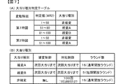
尚、本実施例では、前述したようにスーパーリーチβ、スーパーリーチα、ノーマルリーチの順に変動表示結果が「大当り」となる大当り期待度が高くなるように設定されているため、ノーマルリーチ変動パターン及びスーパーリーチ変動パターンにおいては変動時間が長いほど大当り期待度が高くなっている。 In this embodiment, as described above, the normal reach fluctuation pattern and the super In the reach fluctuation pattern, the longer the fluctuation time, the higher the expectation of a big hit.

尚、本実施例においては、後述するように、これら変動パターンを、例えば、非リーチの種別や、ノーマルリーチの種別や、スーパーリーチの種別等のように、変動パターンの種別を先に決定してから、該決定した種別に属する変動パターンに属する変動パターンから実行する変動パターンを決定するのではなく、これらの種別を決定することなしに変動パターン判定用の乱数値MR3のみを用いて決定するようにしているが、本発明はこれに限定されるものではなく、たとえば、変動パターン判定用の乱数値MR3に加えて、変動パターン種別判定用の乱数値を設けて、これら変動パターン種別判定用の乱数値から変動パターンの種別を先に決定してから、該決定した種別に属する変動パターンに属する変動パターンから実行する変動パターンを決定するようにしても良い。 In this embodiment, as will be described later, these fluctuation patterns are determined first, such as a non-reach type, a normal reach type, a super reach type, and the like. Therefore, instead of determining the variation pattern to be executed from the variation pattern belonging to the determined type, it is determined using only the random value MR3 for determining the variation pattern without determining these types. However, the present invention is not limited to this. For example, in addition to the random value MR3 for determining the variation pattern, a random value for determining the variation pattern type is provided to determine these variation pattern types. The type of the variation pattern may be determined first from the random number value, and then the variation pattern to be executed may be determined from the variation patterns belonging to the variation pattern belonging to the determined type.

図2に示す遊技制御用マイクロコンピュータ100が備えるROM101には、ゲーム制御用のプログラムの他にも、遊技の進行を制御するために用いられる各種の選択用データ、テーブルデータなどが格納されている。例えば、ROM101には、CPU103が各種の判定や決定、設定を行うために予め用意された複数の判定テーブルや設定テーブルなどを構成するデータが記憶されている。また、ROM101には、CPU103が主基板11から各種の制御コマンドとなる制御信号を送信するために用いられる複数のコマンドテーブルを構成するテーブルデータや、図5に示すような変動パターンを複数種類格納する変動パターンテーブルを構成するテーブルデータなどが、記憶されている。 The ROM 101 included in the game control microcomputer 100 shown in FIG. 2 stores various selection data, table data, and the like used for controlling the progress of the game, in addition to the game control program. .. For example, the ROM 101 stores data constituting a plurality of determination tables and setting tables prepared in advance for the CPU 103 to perform various determinations, determinations, and settings. Further, the ROM 101 stores table data constituting a plurality of command tables used for the CPU 103 to transmit control signals to be various control commands from the main board 11, and a plurality of types of fluctuation patterns as shown in FIG. Table data and the like that make up the fluctuation pattern table are stored.

図6は、ROM101に記憶される表示結果判定テーブルの構成例を示している。本実施例では、表示結果判定テーブルとして、第1特図と第2特図とで共通の表示結果判定テーブルを用いているが、本発明はこれに限定されるものではなく、第1特図と第2特図とで個別の表示結果判定テーブルを用いるようにしても良い。 FIG. 6 shows a configuration example of the display result determination table stored in the ROM 101. In the present embodiment, the display result determination table common to the first special figure and the second special figure is used as the display result determination table, but the present invention is not limited to this, and the first special figure is not limited to this. And the second special figure may use individual display result determination tables.

表示結果判定テーブルは、第1特別図柄表示器4Aによる第1特図を用いた特図ゲームや第2特別図柄表示器4Bによる第2特図を用いた特図ゲームにおいて変動表示結果となる確定特別図柄が導出表示される以前に、その変動表示結果を「大当り」として大当り遊技状態に制御するか否かを、特図表示結果判定用の乱数値MR1に基づいて決定するために参照されるテーブルである。 The display result determination table is determined to be a variable display result in the special figure game using the first special figure by the first special symbol display 4A and the special figure game using the second special figure by the second special symbol display 4B. Before the special symbol is derived and displayed, it is referred to to determine whether or not to control the variable display result as a "big hit" to the big hit game state based on the random number value MR1 for determining the special symbol display result. It's a table.

本実施例の表示結果判定テーブルでは、パチンコ遊技機1における遊技状態が通常状態または時短状態(低確状態)であるか、確変状態(高確状態)であるかに応じて、特図表示結果判定用の乱数値MR1と比較される数値(判定値)が、「大当り」や「はずれ」の特図表示結果に割り当てられている。 In the display result determination table of this embodiment, the special figure display result is shown according to whether the gaming state in the pachinko gaming machine 1 is a normal state, a time saving state (low probability state), or a probability change state (high probability state). A numerical value (judgment value) to be compared with the random value MR1 for determination is assigned to the special figure display result of "big hit" or "missing".

表示結果判定テーブルにおいて、特図表示結果判定用の乱数値MR1と比較される判定値を示すテーブルデータは、特図表示結果を「大当り」として大当り遊技状態に制御するか否かの決定結果に割り当てられる判定用データとなっている。本実施例の表示結果判定テーブルでは、遊技状態が確変状態(高確状態)であるときに、通常状態または時短状態(低確状態)であるときよりも多くの判定値が、「大当り」の特図表示結果に割り当てられている。これにより、パチンコ遊技機1において確変制御が行われる確変状態(高確状態)では、通常状態または時短状態(低確状態)であるときに特図表示結果を「大当り」として大当り遊技状態に制御すると決定される確率(本実施例では約1/300)に比べて、特図表示結果を「大当り」として大当り遊技状態に制御すると決定される確率が高くなる(本実施例では約1/30)。即ち、表示結果判定テーブルでは、パチンコ遊技機1における遊技状態が確変状態(高確状態)であるときに、通常状態や時短状態であるときに比べて大当り遊技状態に制御すると決定される確率が高くなるように、判定用データが大当り遊技状態に制御するか否かの決定結果に割り当てられている。 In the display result determination table, the table data indicating the determination value to be compared with the random number value MR1 for determining the special figure display result is used as the determination result of whether or not to control the special figure display result as a "big hit" to the big hit game state. It is the judgment data to be assigned. In the display result judgment table of this embodiment, when the game state is the probability change state (high probability state), more judgment values are "big hit" than when the game state is the normal state or the time saving state (low probability state). It is assigned to the special figure display result. As a result, in the probability change state (high probability state) in which the probability change control is performed in the pachinko gaming machine 1, the special figure display result is set as a "big hit" and controlled to the big hit game state in the normal state or the time saving state (low probability state). Then, the probability of being determined to control the special figure display result as a "big hit" to the big hit gaming state is higher than the probability of being determined (about 1/300 in this embodiment) (about 1/30 in this embodiment). ). That is, in the display result determination table, there is a probability that when the gaming state of the pachinko gaming machine 1 is in the probability variation state (high probability state), it is determined to control the jackpot gaming state as compared with the case of the normal state or the time saving state. The determination data is assigned to the determination result of whether or not to control the jackpot gaming state so as to be higher.

図7は、ROM101に記憶される大当り種別判定テーブルの構成例を示している。本実施例の大当り種別判定テーブルは、特図表示結果を「大当り」として大当り遊技状態に制御すると決定されたときに、大当り種別判定用の乱数値MR2に基づき、大当り種別を複数種類のいずれかに決定するために参照されるテーブルである。大当り種別判定テーブルでは、特図ゲームにおいて変動表示(変動)が行われた特別図柄が第1特図(第1特別図柄表示器4Aによる特図ゲーム)であるか第2特図(第2特別図柄表示器4Bによる特図ゲーム)であるかに応じて、大当り種別判定用の乱数値MR2と比較される数値(判定値)が、「非確変」や「確変大当りA」、「確変大当りB」といった複数種類の大当り種別に割り当てられている。 FIG. 7 shows a configuration example of the jackpot type determination table stored in the ROM 101. In the jackpot type determination table of this embodiment, when it is determined that the special figure display result is "big hit" and the jackpot game state is controlled, the jackpot type is selected from any of a plurality of types based on the random number value MR2 for determining the jackpot type. The table referenced to determine. In the jackpot type determination table, whether the special symbol whose variation is displayed (variable) in the special symbol game is the first special symbol (special symbol game by the first special symbol display 4A) or the second special symbol (second special symbol). The numerical value (judgment value) to be compared with the random number value MR2 for determining the jackpot type is "non-probability variation", "probability variation jackpot A", or "probability variation jackpot B" depending on whether the game is a special figure game using the symbol display 4B). It is assigned to multiple types of jackpots such as ".

ここで、本実施例における大当り種別について、図7(B)を用いて説明すると、本実施例では、大当り種別として、大当り遊技状態の終了後において高確制御と時短制御とが実行されて高確高ベース状態に移行する確変大当りAや確変大当りBと、大当り遊技状態の終了後において時短制御のみが実行されて低確高ベース状態に移行する非確変大当りとが設定されている。 Here, the jackpot type in this embodiment will be described with reference to FIG. 7B. In this embodiment, high accuracy control and time saving control are executed as the jackpot type after the end of the jackpot game state. Probability change jackpot A and probability variation jackpot B that shift to the probability high base state, and non-probability change jackpot that shifts to the low probability variation base state by executing only the time saving control after the end of the jackpot game state are set.

「確変大当りA」による大当り遊技状態と「非確変大当り」による大当り遊技状態では、前述したように、特別可変入賞球装置7を遊技者にとって有利な第1状態に変化させるラウンドが16回(いわゆる16ラウンド)、繰返し実行される通常開放大当りである。一方、「確変大当りB」による大当り遊技状態では、前述したように、特別可変入賞球装置7を遊技者にとって有利な第1状態に変化させるラウンドが5回(いわゆる5ラウンド)、繰返し実行される短期開放大当りである。よって、「確変大当りA」を16ラウンド(16R)確変大当りと呼称し、「確変大当りB」を5ラウンド(5R)確変大当りと呼称する場合がある。 In the big hit game state by "probability change big hit A" and the big hit game state by "non-probability change big hit", as described above, the special variable winning ball device 7 is changed to the first state which is advantageous for the player 16 times (so-called). 16 rounds), a normally open jackpot that is repeatedly executed. On the other hand, in the big hit game state by the "probability change big hit B", as described above, the round for changing the special variable winning ball device 7 to the first state advantageous to the player is repeatedly executed five times (so-called 5 rounds). It is a short-term open jackpot. Therefore, the "probability change jackpot A" may be referred to as a 16-round (16R) probability variation jackpot, and the "probability variation jackpot B" may be referred to as a 5-round (5R) probability variation jackpot.

確変大当りAや確変大当りBの大当り遊技状態の終了後において実行される高確制御と時短制御は、該大当り遊技状態の終了後において再度大当りが発生するまで継続して実行される。よって、再度発生した大当りが確変大当りAや確変大当りBである場合には、大当り遊技状態の終了後に再度、高確制御と時短制御が実行されるので、大当り遊技状態が通常状態を介することなく連続的に発生する、いわゆる連荘状態となる。 The high-accuracy control and the time-saving control executed after the end of the jackpot gaming state of the probabilistic jackpot A and the probabilistic jackpot B are continuously executed until the jackpot occurs again after the end of the jackpot gaming state. Therefore, when the jackpot that occurs again is the probability variation jackpot A or the probability variation jackpot B, the high accuracy control and the time saving control are executed again after the end of the jackpot gaming state, so that the jackpot gaming state does not go through the normal state. It becomes a so-called consecutive villa state that occurs continuously.

一方、「非確変大当り」による大当り遊技状態の終了後において実行される時短制御は、所定回数(本実施例では100回)の特図ゲームが実行されること、或いは該所定回数の特図ゲームが実行される前に大当り遊技状態となることにより終了する。 On the other hand, the time saving control executed after the end of the big hit game state by the "non-probability change big hit" is that the special figure game is executed a predetermined number of times (100 times in this embodiment), or the special figure game of the predetermined number of times. It ends when it becomes a big hit game state before it is executed.

図7(A)に示す大当り種別判定テーブルの設定例では、変動特図が第1特図であるか第2特図であるかに応じて、「確変大当りA」と「確変大当りB」の大当り種別に対する判定値の割当てが異なっている。即ち、変動特図が第1特図である場合には、所定範囲の判定値(「81」〜「100」の範囲の値)がラウンド数の少ない「確変大当りB」の大当り種別に割り当てられる一方で、変動特図が第2特図である場合には、「確変大当りB」の大当り種別に対して判定値が割り当てられていない。このような設定により、第1特別図柄表示器4Aによる第1特図を用いた特図ゲームを開始するための第1開始条件が成立したことに基づいて大当り種別を複数種類のいずれかに決定する場合と、第2特別図柄表示器4Bによる第2特図を用いた特図ゲームを開始するための第2開始条件が成立したことに基づいて大当り種別を複数種類のいずれかに決定する場合とで、大当り種別をラウンド数の少ない「確変大当りB」に決定する割合を、異ならせることができる。特に、第2特図を用いた特図ゲームでは大当り種別を「確変大当りB」としてラウンド数の少ない短期開放大当り状態に制御すると決定されることがないので、例えば時短制御に伴う高開放制御により、普通可変入賞球装置6Bが形成する第2始動入賞口に遊技球が進入しやすい遊技状態において、得られる賞球が少ない短期開放大当り状態の頻発を回避して遊技興趣が低下してしまうことを防止できるようになっている。 In the setting example of the jackpot type determination table shown in FIG. 7 (A), "probability variation jackpot A" and "probability variation jackpot B" are set according to whether the fluctuation special figure is the first special figure or the second special figure. The allocation of judgment values for the jackpot type is different. That is, when the variable special figure is the first special figure, the judgment value in a predetermined range (value in the range of "81" to "100") is assigned to the big hit type of "probability variable big hit B" with a small number of rounds. On the other hand, when the variable special figure is the second special figure, the determination value is not assigned to the big hit type of "probability variation big hit B". With such a setting, the jackpot type is determined to be one of a plurality of types based on the fact that the first start condition for starting the special figure game using the first special figure by the first special symbol display 4A is satisfied. When the jackpot type is determined to be one of a plurality of types based on the establishment of the second start condition for starting the special figure game using the second special figure by the second special symbol display 4B. Therefore, the ratio of determining the jackpot type to "probability variation jackpot B" with a small number of rounds can be made different. In particular, in the special figure game using the second special figure, it is not determined that the jackpot type is set to "probability variation jackpot B" and controlled to the short-term open jackpot state with a small number of rounds. In a gaming state in which a game ball easily enters the second starting winning opening formed by the normally variable winning ball device 6B, the game interest is reduced by avoiding the frequent occurrence of a short-term open jackpot state in which a small number of winning balls can be obtained. Can be prevented.

尚、図7(A)に示す大当り種別判定テーブルの設定例では、「非確変」の大当り種別に対する判定値の割当ては、変動特図が第1特図であるか第2特図であるかに係わらず同一とされているので、非確変の大当りとなる確率と確変の大当りとなる確率は、変動特図が第1特図であるか第2特図であるかにかかわらず同一とされている。 In the setting example of the jackpot type determination table shown in FIG. 7A, the allocation of the determination value for the jackpot type of "non-probability variation" is whether the fluctuation special figure is the first special figure or the second special figure. Since it is the same regardless of the fact, the probability of becoming a non-probability jackpot and the probability of becoming a probabilistic jackpot are the same regardless of whether the fluctuation special figure is the first special figure or the second special figure. ing.

よって、上記したように、「確変大当りB」に対する判定値の割り当てが、変動特図が第1特図であるか第2特図であるかに応じて異なることに応じて、「確変大当りA」に対する判定値の割り当ても変動特図が第1特図であるか第2特図であるかに応じて異なり、ラウンド数の多い「確変大当りA」については、変動特図が第2特図である場合の方が第1特図である場合よりも決定され易くなるように設定されている。 Therefore, as described above, the assignment of the judgment value to the "probability change jackpot B" differs depending on whether the fluctuation special figure is the first special figure or the second special figure, and the "probability change jackpot A" is used. The assignment of the judgment value to "" also differs depending on whether the variable special figure is the first special figure or the second special figure, and for "probability variable jackpot A" with a large number of rounds, the variable special figure is the second special figure. It is set so that the case of is easier to determine than the case of the first special figure.

尚、変動特図が第2特図である場合にも、変動特図が第1特図である場合とは異なる所定範囲の判定値が、「確変大当りB」の大当り種別に割り当てられるようにしてもよい。例えば、変動特図が第2特図である場合には、変動特図が第1特図である場合に比べて少ない判定値が、「確変大当りB」の大当り種別に割り当てられてもよい。あるいは、変動特図が第1特図であるか第2特図であるかにかかわらず、共通のテーブルデータを参照して、大当り種別の決定を行うようにしてもよい。 Even when the variable special figure is the second special figure, a judgment value in a predetermined range different from the case where the variable special figure is the first special figure is assigned to the big hit type of "probability variable big hit B". You may. For example, when the variable special figure is the second special figure, a smaller determination value than when the variable special figure is the first special figure may be assigned to the big hit type of "probability variable big hit B". Alternatively, regardless of whether the variable special figure is the first special figure or the second special figure, the jackpot type may be determined by referring to the common table data.

また、ROM101には、変動パターン判定用の乱数値MR3に基づいて変動パターンを決定するための変動パターン判定テーブルも記憶されており、変動パターンを、事前決定結果に応じて前述した複数種類のうちのいずれかの変動パターンに決定する。 Further, the ROM 101 also stores a variation pattern determination table for determining the variation pattern based on the random number value MR3 for determining the variation pattern, and the variation pattern can be selected from the plurality of types described above according to the predetermined determination result. Determine to one of the fluctuation patterns of.

具体的には、変動パターン判定テーブルとしては、特図表示結果を「大当り」にすることが事前決定されたときに使用される大当り用変動パターン判定テーブルと、特図表示結果を「はずれ」にすることが事前決定されたときに使用されるはずれ用変動パターン判定テーブルとが予め用意されている。 Specifically, as the fluctuation pattern judgment table, the fluctuation pattern judgment table for big hits used when it is determined in advance that the special figure display result is "big hit" and the special figure display result are "missing". A variation pattern determination table for deviation, which is used when it is determined in advance to be performed, is prepared in advance.

大当り用変動パターン判定テーブルにおいては、ノーマルリーチ大当りの変動パターン(PB1−1)、スーパーリーチα大当りの変動パターン(PB1−2)、スーパーリーチβ大当りの変動パターン(PB1−3)の各変動パターンに対して、変動パターン判定用の乱数値MR3がとりうる範囲のうち所定の乱数値が判定値として割り当てられている。尚、本実施例では、これらの判定値が、大当りの種別が「確変大当りA」または「確変大当りB」である場合にはスーパーリーチβが決定され易く、大当りの種別が「非確変大当り」である場合には、スーパーリーチαが決定され易いように割り当てられていることで、スーパーリーチβの変動パターンが実行されたときには、「確変大当りA」または「確変大当りB」となるのではないかという遊技者の期待感を高めることできる。 In the jackpot fluctuation pattern determination table, the fluctuation patterns of the normal reach jackpot (PB1-1), the fluctuation pattern of the super reach α jackpot (PB1-2), and the fluctuation pattern of the super reach β jackpot (PB1-3) are used. On the other hand, a predetermined random number value is assigned as the determination value in the range that the random number value MR3 for determining the fluctuation pattern can take. In this embodiment, when the type of jackpot is "probability variation jackpot A" or "probability variation jackpot B", the super reach β is easily determined, and the jackpot type is "non-probability variation jackpot". In the case of, the super reach α is assigned so as to be easily determined, so that when the fluctuation pattern of the super reach β is executed, it does not become “probability change jackpot A” or “probability variation jackpot B”. It is possible to raise the expectation of the player.

また、はずれ用変動パターン判定テーブルには、保留記憶数が1個以下である場合に使用されるはずれ用変動パターン判定テーブルAと、合計保留記憶数が2〜4個である場合に使用されるはずれ用変動パターン判定テーブルBと、合計保留記憶数が5〜8個である場合に使用されるはずれ用変動パターン判定テーブルCと、遊技状態が時短制御の実施されている高ベース状態である場合に使用されるはずれ用変動パターン判定テーブルDとが予め用意されている。 Further, the deviation pattern determination table is used when the number of reserved storages is 1 or less and the deviation pattern determination table A is used, and when the total number of reserved storages is 2 to 4. The variation pattern determination table B for deviation, the variation pattern determination table C for deviation used when the total number of reserved storages is 5 to 8, and the game state is a high base state in which time reduction control is implemented. The deviation pattern determination table D used for the above is prepared in advance.

はずれ用変動パターン判定テーブルAにおいては、短縮なしの非リーチはずれの変動パターン(PA1−1)、ノーマルリーチはずれの変動パターン(PA2−1)、スーパーリーチαはずれの変動パターン(PA2−2)、スーパーリーチβはずれの変動パターン(PA2−3)に対して変動パターン判定用の乱数値MR3がとりうる範囲のうち所定の乱数値が判定値として割り当てられている。また、はずれ用変動パターン判定テーブルBにおいては、合計保留記憶数が2〜4個に対応する短縮の非リーチはずれの変動パターン(PA1−2)、ノーマルリーチはずれの変動パターン(PA2−1)、スーパーリーチαはずれの変動パターン(PA2−2)、スーパーリーチβはずれの変動パターン(PA2−3)に対して変動パターン判定用の乱数値MR3がとりうる範囲のうち所定の乱数値が判定値として割り当てられている。また、はずれ用変動パターン判定テーブルCにおいては、合計保留記憶数が5〜8個に対応する短縮の非リーチはずれの変動パターン(PA1−3)、ノーマルリーチはずれの変動パターン(PA2−1)、スーパーリーチαはずれの変動パターン(PA2−2)、スーパーリーチβはずれの変動パターン(PA2−3)に対して変動パターン判定用の乱数値MR3がとりうる範囲のうち所定の乱数値が判定値として割り当てられている。また、はずれ用変動パターン判定テーブルDにおいては、時短制御中に対応する短縮の非リーチはずれの変動パターン(PA1−4)、ノーマルリーチはずれの変動パターン(PA2−1)、スーパーリーチαはずれの変動パターン(PA2−2)、スーパーリーチβはずれの変動パターン(PA2−3)に対して変動パターン判定用の乱数値MR3がとりうる範囲のうち所定の乱数値が判定値として割り当てられている。 In the deviation pattern determination table A, the non-reach deviation variation pattern without shortening (PA1-1), the normal reach deviation variation pattern (PA2-1), the super reach α deviation variation pattern (PA2-2), and the super A predetermined random number value within the range that the random number value MR3 for determining the variation pattern can take is assigned as the determination value to the variation pattern (PA2-3) out of reach β. Further, in the deviation pattern determination table B, the shortened non-reach deviation variation pattern (PA1-2), the normal reach deviation variation pattern (PA2-1), and the super A predetermined random number value within the range that the random number value MR3 for determining the variation pattern can be assigned to the variation pattern (PA2-2) out of reach α and the variation pattern (PA2-3) out of reach β is assigned as the determination value. Has been done. Further, in the deviation pattern determination table C, the shortened non-reach deviation variation pattern (PA1-3), the normal reach deviation variation pattern (PA2-1), and the super A predetermined random number value within the range that the random number value MR3 for determining the variation pattern can be assigned to the variation pattern (PA2-2) out of reach α and the variation pattern (PA2-3) out of reach β is assigned as the determination value. Has been done. Further, in the deviation pattern determination table D, the shortening non-reach deviation variation pattern (PA1-4), the normal reach deviation variation pattern (PA2-1), and the super reach α deviation variation pattern corresponding to the time reduction control are performed. (PA2-2), a predetermined random number value within the range that the random number value MR3 for determining the fluctuation pattern can take is assigned as the determination value to the fluctuation pattern (PA2-3) out of the super reach β.

尚、図5に示すように、短縮なしの非リーチはずれの変動パターン(PA1−1)よりも非リーチはずれの変動パターン(PA1−2)の方が変動時間は短く、更に、変動パターン(PA1−2)よりも非リーチはずれの変動パターン(PA1−3)の方が変動時間は短い。よって、保留記憶数が増加した場合には、変動時間が短い非リーチはずれの変動パターンが決定されることにより、保留記憶が消化されやすくなって、保留記憶数が上限数である4に達しているときに始動入賞することで、保留記憶がなされない無駄な始動入賞が発生し難くなるようになるとともに、保留記憶数が減少した場合には、変動時間が長い短縮なしの非リーチはずれの変動パターン(PA1−1)が決定されることによって、変動表示の時間が長くなることにより、変動表示が実行されないことによる遊技の興趣低下を防ぐことができるようになる。 As shown in FIG. 5, the variation pattern (PA1-2) without shortening has a shorter variation time than the variation pattern (PA1-1) without shortening, and further, the variation pattern (PA1). The fluctuation time of the non-reach out-of-reach fluctuation pattern (PA1-3) is shorter than that of -2). Therefore, when the number of reserved memories increases, the non-reach out-of-reach fluctuation pattern with a short fluctuation time is determined, so that the reserved memories are easily digested, and the number of reserved memories reaches the upper limit of 4. By winning a start prize while the player is in the game, it becomes difficult for a useless start prize to be stored, and when the number of stored memories decreases, the fluctuation time is long and the non-reach is out of reach. By determining the pattern (PA1-1), the time of the variable display becomes long, so that it is possible to prevent the game from being less interesting due to the variable display not being executed.

図2に示す遊技制御用マイクロコンピュータ100が備えるRAM102は、その一部または全部が所定の電源基板において作成されるバックアップ電源によってバックアップされているバックアップRAMであればよい。即ち、パチンコ遊技機1に対する電力供給が停止しても、所定期間(バックアップ電源としてのコンデンサが放電してバックアップ電源が電力供給不能になるまで)は、RAM102の一部または全部の内容は保存される。特に、少なくとも、遊技状態、即ち遊技制御手段の制御状態に応じたデータ(特図プロセスフラグなど)と未払出賞球数を示すデータとは、バックアップRAMに保存されるようにすればよい。遊技制御手段の制御状態に応じたデータとは、停電等が生じた後に復旧した場合に、そのデータにもとづいて、制御状態を停電等の発生前に復旧させるために必要なデータである。また、制御状態に応じたデータと未払出賞球数を示すデータとを遊技の進行状態を示すデータと定義する。 The RAM 102 included in the game control microcomputer 100 shown in FIG. 2 may be a backup RAM in which a part or all of the RAM 102 is backed up by a backup power source created on a predetermined power supply board. That is, even if the power supply to the pachinko gaming machine 1 is stopped, a part or all of the contents of the RAM 102 are stored for a predetermined period (until the capacitor as the backup power supply is discharged and the backup power supply cannot be supplied with power). NS. In particular, at least the game state, that is, the data corresponding to the control state of the game control means (such as the special figure process flag) and the data indicating the number of unpaid prize balls may be stored in the backup RAM. The data according to the control state of the game control means is data necessary for recovering the control state before the occurrence of the power failure or the like based on the data when the data is restored after the power failure or the like occurs. Further, the data corresponding to the control state and the data indicating the number of unpaid prize balls are defined as the data indicating the progress state of the game.

このようなRAM102には、パチンコ遊技機1における遊技の進行などを制御するために用いられる各種のデータを保持する領域として、例えば図8に示すような遊技制御用データ保持エリア150が設けられている。図8に示す遊技制御用データ保持エリア150は、第1特図保留記憶部151Aと、第2特図保留記憶部151Bと、普図保留記憶部151Cと、遊技制御フラグ設定部152と、遊技制御タイマ設定部153と、遊技制御カウンタ設定部154と、遊技制御バッファ設定部155とを備えている。 The RAM 102 is provided with a game control data holding area 150 as shown in FIG. 8, for example, as an area for holding various data used for controlling the progress of the game in the pachinko gaming machine 1. There is. The game control data holding area 150 shown in FIG. 8 includes a first special figure holding storage unit 151A, a second special figure holding storage unit 151B, a normal drawing holding storage unit 151C, a game control flag setting unit 152, and a game. It includes a control timer setting unit 153, a game control counter setting unit 154, and a game control buffer setting unit 155.

第1特図保留記憶部151Aは、普通入賞球装置6Aが形成する第1始動入賞口を遊技球が通過(進入)して始動入賞(第1始動入賞)が発生したものの未だ開始されていない特図ゲーム(第1特別図柄表示器4Aにおける第1特図を用いた特図ゲーム)の保留データを記憶する。一例として、第1特図保留記憶部151Aは、第1始動入賞口への入賞順(遊技球の検出順)に保留番号と関連付けて、その遊技球の通過(進入)における第1始動条件の成立に基づいてCPU103により乱数回路104等から抽出された特図表示結果判定用の乱数値MR1や大当り種別判定用の乱数値MR2、変動パターン判定用の乱数値MR3を示す数値データなどを保留データとして、その記憶数が所定の上限値(例えば「4」)に達するまで記憶する。こうして第1特図保留記憶部151Aに記憶された保留データは、第1特図を用いた特図ゲームの実行が保留されていることを示し、この特図ゲームにおける変動表示結果(特図表示結果)に基づき大当りとなるか否かなどを判定可能にする保留情報となる。 The first special figure reservation storage unit 151A has not been started yet, although the game ball has passed (entered) the first starting winning opening formed by the normal winning ball device 6A and the starting winning (first starting winning) has occurred. The reserved data of the special figure game (the special figure game using the first special figure in the first special symbol display 4A) is stored. As an example, the first special figure reservation storage unit 151A associates the winning order (the order of detecting the game ball) with the holding number with the first starting winning opening, and sets the first starting condition in the passage (entry) of the game ball. Hold data such as a random number value MR1 for determining a special figure display result, a random number value MR2 for determining a jackpot type, and a random number value MR3 for determining a fluctuation pattern extracted from a random number circuit 104 or the like by the CPU 103 based on the establishment. As a result, the data is stored until the number of stored data reaches a predetermined upper limit value (for example, "4"). The hold data stored in the first special figure hold storage unit 151A in this way indicates that the execution of the special figure game using the first special figure is suspended, and the variation display result (special figure display) in this special figure game. Based on the result), it becomes the pending information that makes it possible to judge whether or not it will be a big hit.

第2特図保留記憶部151Bは、普通可変入賞球装置6Bが形成する第2始動入賞口を遊技球が通過(進入)して始動入賞(第2始動入賞)が発生したものの未だ開始されていない特図ゲーム(第2特別図柄表示器4Bにおける第2特図を用いた特図ゲーム)の保留データを記憶する。一例として、第2特図保留記憶部151Bは、第2始動入賞口への入賞順(遊技球の検出順)に保留番号と関連付けて、その遊技球の通過(進入)における第2始動条件の成立に基づいてCPU103により乱数回路104等から抽出された特図表示結果判定用の乱数値MR1や大当り種別判定用の乱数値MR2、変動パターン判定用の乱数値MR3を示す数値データなどを保留データとして、その数が所定の上限値(例えば「4」)に達するまで記憶する。こうして第2特図保留記憶部151Bに記憶された保留データは、第2特図を用いた特図ゲームの実行が保留されていることを示し、この特図ゲームにおける変動表示結果(特図表示結果)に基づき大当りとなるか否かなどを判定可能にする保留情報となる。 The second special figure reservation storage unit 151B is still started although the game ball passes (enters) the second starting winning opening formed by the normally variable winning ball device 6B and the starting winning (second starting winning) is generated. Stores the reserved data of a special figure game (a special figure game using the second special figure on the second special symbol display 4B). As an example, the second special figure reservation storage unit 151B associates the winning order (the order of detecting the game ball) with the holding number with the second starting winning opening, and sets the second starting condition in the passage (entry) of the game ball. Hold data such as a random number value MR1 for determining a special figure display result, a random number value MR2 for determining a jackpot type, and a random number value MR3 for determining a fluctuation pattern extracted from a random number circuit 104 or the like by the CPU 103 based on the establishment. As a result, the number is stored until it reaches a predetermined upper limit value (for example, "4"). The hold data stored in the second special figure hold storage unit 151B in this way indicates that the execution of the special figure game using the second special figure is suspended, and the variation display result (special figure display) in this special figure game. Based on the result), it becomes the pending information that makes it possible to judge whether or not it will be a big hit.

尚、第1始動入賞口を遊技球が通過(進入)したことによる第1始動条件の成立に基づく保留情報(第1保留情報)と、第2始動入賞口を遊技球が通過(進入)したことによる第2始動入賞の成立に基づく保留情報(第2保留情報)とを、共通の保留記憶部にて保留番号と対応付けて記憶するようにしてもよい。この場合には、第1始動入賞口と第2始動入賞口のいずれを遊技球が通過(進入)したかを示す始動口データを保留情報に含め、保留番号と対応付けて記憶させればよい。 It should be noted that the hold information (first hold information) based on the establishment of the first start condition due to the game ball passing (entering) through the first start winning opening and the game ball passing (entering) through the second start winning opening. The hold information (second hold information) based on the establishment of the second start winning prize may be stored in association with the hold number in the common hold storage unit. In this case, the start port data indicating which of the first start winning opening and the second starting winning opening the game ball has passed (entered) may be included in the hold information and stored in association with the hold number. ..

普図保留記憶部151Cは、通過ゲート41を通過した遊技球がゲートスイッチ21によって検出されたにもかかわらず、未だ普通図柄表示器20により開始されていない普図ゲームの保留情報を記憶する。例えば、普図保留記憶部151Cは、遊技球が通過ゲート41を通過した順に保留番号と対応付けて、その遊技球の通過に基づいてCPU103により乱数回路104等から抽出された普図表示結果判定用の乱数値MR4を示す数値データなどを保留データとして、その数が所定の上限値(例えば「4」)に達するまで記憶する。 The normal figure hold storage unit 151C stores the hold information of the normal figure game that has not yet been started by the normal symbol display 20 even though the game ball that has passed through the passing gate 41 is detected by the gate switch 21. For example, the normal map holding storage unit 151C associates the game ball with the hold number in the order of passing through the passing gate 41, and determines the normal figure display result extracted from the random number circuit 104 or the like by the CPU 103 based on the passing of the game ball. Numerical data indicating the random number value MR4 for use is set as pending data, and is stored until the number reaches a predetermined upper limit value (for example, “4”).

遊技制御フラグ設定部152には、パチンコ遊技機1における遊技の進行状況などに応じて状態を更新可能な複数種類のフラグが設けられている。例えば、遊技制御フラグ設定部152には、複数種類のフラグそれぞれについて、フラグの値を示すデータや、オン状態あるいはオフ状態を示すデータが記憶される。 The game control flag setting unit 152 is provided with a plurality of types of flags whose state can be updated according to the progress of the game in the pachinko gaming machine 1. For example, the game control flag setting unit 152 stores data indicating a flag value and data indicating an on state or an off state for each of a plurality of types of flags.

遊技制御タイマ設定部153には、パチンコ遊技機1における遊技の進行を制御するために用いられる各種のタイマが設けられている。例えば、遊技制御タイマ設定部153には、複数種類のタイマそれぞれにおけるタイマ値を示すデータが記憶される。 The game control timer setting unit 153 is provided with various timers used to control the progress of the game in the pachinko gaming machine 1. For example, the game control timer setting unit 153 stores data indicating timer values for each of a plurality of types of timers.

遊技制御カウンタ設定部154には、パチンコ遊技機1における遊技の進行を制御するために用いられるカウント値を計数するための複数種類のカウンタが設けられている。例えば、遊技制御カウンタ設定部154には、複数種類のカウンタそれぞれにおけるカウント値を示すデータが記憶される。ここで、遊技制御カウンタ設定部154には、遊技用乱数の一部または全部をCPU103がソフトウェアにより更新可能にカウントするためのランダムカウンタが設けられてもよい。 The game control counter setting unit 154 is provided with a plurality of types of counters for counting the count values used for controlling the progress of the game in the pachinko gaming machine 1. For example, the game control counter setting unit 154 stores data indicating count values for each of a plurality of types of counters. Here, the game control counter setting unit 154 may be provided with a random counter for the CPU 103 to count a part or all of the game random numbers so that they can be updated by software.

遊技制御カウンタ設定部154のランダムカウンタには、乱数回路104で生成されない乱数値、例えば、乱数値MR2〜MR4を示す数値データが、ランダムカウント値として記憶され、CPU103によるソフトウェアの実行に応じて、定期的あるいは不定期に、各乱数値を示す数値データが更新される。CPU103がランダムカウント値を更新するために実行するソフトウェアは、ランダムカウント値を乱数回路104における数値データの更新動作とは別個に更新するためのものであってもよいし、乱数回路104から抽出された数値データの全部または一部にスクランブル処理や演算処理といった所定の処理を施すことによりランダムカウント値を更新するためのものであってもよい。 In the random counter of the game control counter setting unit 154, a random number value not generated by the random number circuit 104, for example, numerical data indicating the random number values MR2 to MR4 is stored as a random count value, and according to the execution of the software by the CPU 103, Numerical data indicating each random number value is updated periodically or irregularly. The software executed by the CPU 103 to update the random count value may be for updating the random count value separately from the operation of updating the numerical data in the random number circuit 104, or may be extracted from the random number circuit 104. It may be for updating the random count value by performing a predetermined process such as scramble processing or arithmetic processing on all or a part of the numerical data.

遊技制御バッファ設定部155には、パチンコ遊技機1における遊技の進行を制御するために用いられるデータを一時的に記憶する各種のバッファが設けられている。例えば、遊技制御バッファ設定部155には、複数種類のバッファそれぞれにおけるバッファ値を示すデータが記憶される。 The game control buffer setting unit 155 is provided with various buffers for temporarily storing data used for controlling the progress of the game in the pachinko gaming machine 1. For example, the game control buffer setting unit 155 stores data indicating buffer values in each of a plurality of types of buffers.

図2に示す遊技制御用マイクロコンピュータ100が備えるI/O105は、遊技制御用マイクロコンピュータ100に伝送された各種信号を取り込むための入力ポートと、遊技制御用マイクロコンピュータ100の外部へと各種信号を伝送するための出力ポートとを含んで構成されている。 The I / O 105 included in the game control microcomputer 100 shown in FIG. 2 has an input port for capturing various signals transmitted to the game control microcomputer 100 and various signals to the outside of the game control microcomputer 100. It is configured to include an output port for transmission.

図2に示すように、演出制御基板12には、プログラムに従って制御動作を行う演出制御用CPU120と、演出制御用のプログラムや固定データ等を記憶するROM121と、演出制御用CPU120のワークエリアを提供するRAM122と、演出表示装置5における表示動作の制御内容を決定するための処理などを実行する表示制御部123と、演出制御用CPU120とは独立して乱数値を示す数値データの更新を行う乱数回路124と、I/O125とが搭載されている。 As shown in FIG. 2, the effect control board 12 provides an effect control CPU 120 that performs a control operation according to a program, a ROM 121 that stores an effect control program, fixed data, and the like, and a work area of the effect control CPU 120. RAM 122, a display control unit 123 that executes processing for determining the control content of the display operation in the effect display device 5, and a random number that updates numerical data indicating a random number value independently of the effect control CPU 120. The circuit 124 and the I / O 125 are mounted.

一例として、演出制御基板12では、演出制御用CPU120がROM121から読み出した演出制御用のプログラムを実行することにより、演出用の電気部品による演出動作を制御するための処理が実行される。このときには、演出制御用CPU120がROM121から固定データを読み出す固定データ読出動作や、演出制御用CPU120がRAM122に各種の変動データを書き込んで一時記憶させる変動データ書込動作、演出制御用CPU120がRAM122に一時記憶されている各種の変動データを読み出す変動データ読出動作、演出制御用CPU120がI/O125を介して演出制御基板12の外部から各種信号の入力を受け付ける受信動作、演出制御用CPU120がI/O125を介して演出制御基板12の外部へと各種信号を出力する送信動作なども行われる。 As an example, in the effect control board 12, the effect control CPU 120 executes the effect control program read from the ROM 121, thereby executing the process for controlling the effect operation by the effect electric components. At this time, the effect control CPU 120 reads the fixed data from the ROM 121, the effect control CPU 120 writes various variation data to the RAM 122, and the effect control CPU 120 temporarily stores the variation data in the RAM 122. A variable data read operation for reading various temporarily stored variable data, a reception operation in which the effect control CPU 120 receives input of various signals from the outside of the effect control board 12 via the I / O 125, and an effect control CPU 120 is I / A transmission operation for outputting various signals to the outside of the effect control board 12 via the O125 is also performed.

演出制御用CPU120、ROM121、RAM122は、演出制御基板12に搭載された1チップの演出制御用マイクロコンピュータに含まれてもよい。 The effect control CPU 120, ROM 121, and RAM 122 may be included in the one-chip effect control microcomputer mounted on the effect control board 12.

演出制御基板12には、演出表示装置5に対して映像信号を伝送するための配線や、音声制御基板13に対して音番号データを示す情報信号としての効果音信号を伝送するための配線、LED制御基板14に対してLEDデータを示す情報信号としての電飾信号を伝送するための配線などが接続されている。 The effect control board 12 has wiring for transmitting a video signal to the effect display device 5, and wiring for transmitting an effect sound signal as an information signal indicating sound number data to the sound control board 13. Wiring for transmitting an illumination signal as an information signal indicating LED data is connected to the LED control board 14.

尚、演出制御基板12の側においても、主基板11と同様に、例えば、予告演出等の各種の演出の種別を決定するための乱数値(演出用乱数ともいう)が設定されている。 On the side of the effect control board 12, as in the main board 11, for example, a random number value (also referred to as an effect random number) for determining the type of various effects such as a notice effect is set.

図2に示す演出制御基板12に搭載されたROM121には、演出制御用のプログラムの他にも、演出動作を制御するために用いられる各種のデータテーブルなどが格納されている。例えば、ROM121には、演出制御用CPU120が各種の判定や決定、設定を行うために用意された複数の判定テーブルを構成するテーブルデータ、各種の演出制御パターンを構成するパターンデータなどが記憶されている。 The ROM 121 mounted on the effect control board 12 shown in FIG. 2 stores various data tables and the like used for controlling the effect operation in addition to the program for effect control. For example, the ROM 121 stores table data constituting a plurality of determination tables prepared for the effect control CPU 120 to perform various determinations, determinations, and settings, pattern data constituting various effect control patterns, and the like. There is.

一例として、ROM121には、演出制御用CPU120が各種の演出装置(例えば演出表示装置5やスピーカ8L,8R、遊技効果LED9及び装飾用LED、演出用模型など)による演出動作を制御するために使用する演出制御パターンを複数種類格納した演出制御パターンテーブルが記憶されている。演出制御パターンは、パチンコ遊技機1における遊技の進行状況に応じて実行される各種の演出動作に対応して、その制御内容を示すデータなどから構成されている。演出制御パターンテーブルには、例えば特図変動時演出制御パターンと、予告演出制御パターンと、各種演出制御パターン等が、格納されていればよい。 As an example, in the ROM 121, the effect control CPU 120 is used to control the effect operation by various effect devices (for example, the effect display device 5, the speakers 8L, 8R, the game effect LED 9, the decorative LED, the effect model, etc.). An effect control pattern table that stores a plurality of types of effect control patterns to be performed is stored. The effect control pattern is composed of data indicating the control content or the like corresponding to various effect operations executed according to the progress of the game in the pachinko gaming machine 1. The effect control pattern table may store, for example, an effect control pattern when the special figure fluctuates, a notice effect control pattern, various effect control patterns, and the like.

特図変動時演出制御パターンは、複数種類の変動パターンに対応して、特図ゲームにおいて特別図柄の変動が開始されてから特図表示結果となる確定特別図柄が導出表示されるまでの期間における、演出図柄の変動表示動作やリーチ演出、再抽選演出などにおける演出表示動作、あるいは、演出図柄の変動表示を伴わない各種の演出表示動作といった、様々な演出動作の制御内容を示すデータなどから構成されている。予告演出制御パターンは、例えば、予め複数パターンが用意された予告パターンに対応して実行される予告演出となる演出動作の制御内容を示すデータなどから構成されている。各種演出制御パターンは、パチンコ遊技機1における遊技の進行状況に応じて実行される各種の演出動作に対応して、その制御内容を示すデータなどから構成されている。 The effect control pattern at the time of special symbol fluctuation corresponds to a plurality of types of fluctuation patterns, and is in the period from the start of fluctuation of the special symbol in the special symbol game to the derivation display of the definite special symbol which is the special symbol display result. , It is composed of data showing the control contents of various production operations such as the variable display operation of the effect symbol, the reach effect, the effect display operation in the re-lottery effect, or various effect display operations without the variable display of the effect symbol. Has been done. The advance notice effect control pattern is composed of, for example, data indicating the control content of the effect operation that is the advance notice effect executed in response to the advance notice patterns in which a plurality of patterns are prepared in advance. The various effect control patterns are composed of data indicating the control contents and the like corresponding to various effect operations executed according to the progress of the game in the pachinko gaming machine 1.

特図変動時演出制御パターンのうちには、例えばリーチ演出を実行する変動パターンごとに、それぞれのリーチ演出における演出態様を異ならせた複数種類のリーチ演出制御パターンが含まれてもよい。 The special figure variation time effect control pattern may include, for example, a plurality of types of reach effect control patterns in which the effect mode in each reach effect is different for each variation pattern for executing the reach effect.

図2に示す演出制御基板12に搭載されたRAM122には、演出動作を制御するために用いられる各種データを保持する領域として、図示しない演出制御用データ保持エリアが設けられている。この演出制御用データ保持エリアは、演出制御フラグ設定部と、演出制御タイマ設定部と、演出制御カウンタ設定部と、演出制御バッファ設定部とを備えている。 The RAM 122 mounted on the effect control board 12 shown in FIG. 2 is provided with an effect control data holding area (not shown) as an area for holding various data used for controlling the effect operation. This effect control data holding area includes an effect control flag setting unit, an effect control timer setting unit, an effect control counter setting unit, and an effect control buffer setting unit.

演出制御フラグ設定部には、例えば演出表示装置5の画面上における演出画像の表示状態などといった演出動作状態や主基板11から伝送された演出制御コマンド等に応じて状態を更新可能な複数種類のフラグが設けられている。例えば、演出制御フラグ設定部には、複数種類のフラグそれぞれについて、フラグの値を示すデータや、オン状態あるいはオフ状態を示すデータが記憶される。 There are a plurality of types of effect control flag setting units that can update the state according to the effect operation state such as the display state of the effect image on the screen of the effect display device 5 and the effect control command transmitted from the main board 11. A flag is provided. For example, the effect control flag setting unit stores data indicating the value of the flag and data indicating the on state or the off state for each of the plurality of types of flags.

演出制御タイマ設定部には、例えば演出表示装置5の画面上における演出画像の表示動作などといった各種演出動作の進行を制御するために用いられる複数種類のタイマが設けられている。例えば、演出制御タイマ設定部には、複数種類のタイマそれぞれにおけるタイマ値を示すデータが記憶される。 The effect control timer setting unit is provided with a plurality of types of timers used to control the progress of various effect operations such as the display operation of the effect image on the screen of the effect display device 5. For example, the effect control timer setting unit stores data indicating timer values for each of a plurality of types of timers.

演出制御カウンタ設定部には、各種演出動作の進行を制御するために用いられる複数種類のカウンタが設けられている。例えば、演出制御カウンタ設定部には、複数種類のカウンタそれぞれにおけるカウント値を示すデータが記憶される。 The effect control counter setting unit is provided with a plurality of types of counters used to control the progress of various effect operations. For example, the effect control counter setting unit stores data indicating the count values of the plurality of types of counters.

演出制御バッファ設定部には、各種演出動作の進行を制御するために用いられるデータを一時的に記憶する各種のバッファが設けられている。例えば、演出制御バッファ設定部には、複数種類のバッファそれぞれにおけるバッファ値を示すデータが記憶される。 The effect control buffer setting unit is provided with various buffers for temporarily storing data used for controlling the progress of various effect operations. For example, the effect control buffer setting unit stores data indicating buffer values in each of a plurality of types of buffers.

本実施例では、演出制御バッファ設定部の所定領域に、第1保留記憶表示エリア5D及び第2保留記憶表示エリア5Uにて保留記憶表示を行うための始動入賞時受信コマンドバッファが設定されている。始動入賞時受信コマンドバッファには、第1特図保留記憶の合計保留記憶数の最大値(例えば「4」)に対応した格納領域(バッファ番号「1」〜「4」に対応した領域)が設けられており、各格納領域に、始動入賞の有無を示すデータ(具体的には始動入賞無しを示す「0」と、始動入賞有りを示す「1」)とが記憶されている。尚、これら始動入賞時受信コマンドバッファのデータは、第1始動口入賞指定コマンドや第2始動口入賞指定コマンドの受信や、第1変動開始コマンドや第2変動開始コマンドの受信に応じて、後述する演出制御プロセス処理内の保留表示更新処理(S72、図12参照)にて更新されるとともに、更新後の始動入賞時受信コマンドバッファのデータに基づいて第1保留記憶表示エリア5D及び第2保留記憶表示エリア5Uにおける保留記憶表示が更新される。 In this embodiment, a start winning command receive command buffer for performing a hold storage display in the first hold storage display area 5D and the second hold storage display area 5U is set in a predetermined area of the effect control buffer setting unit. .. The command buffer received at the time of starting winning has a storage area (area corresponding to buffer numbers "1" to "4") corresponding to the maximum value (for example, "4") of the total number of reserved storages in the first special figure reserved storage. Data indicating the presence or absence of a start prize (specifically, "0" indicating no start prize and "1" indicating that there is a start prize) are stored in each storage area. The data in the command buffer received at the time of starting winning will be described later in response to the reception of the first starting opening winning designation command, the second starting opening winning designation command, the first fluctuation start command, and the second fluctuation start command. It is updated in the hold display update process (S72, see FIG. 12) in the effect control process process, and the first hold storage display area 5D and the second hold are held based on the data of the received command buffer at the time of starting winning after the update. The hold storage display in the storage display area 5U is updated.

具体的には、第1始動入賞口への始動入賞があったことに基づいて第1始動口入賞指定コマンドを受信したときには、第1保留記憶表示エリア5Dにおける保留記憶表示に、丸型の白色表示が新たに追加される一方、新たに第1特図の変動が開始されたことに基づいて第1変動開始コマンドを受信したときには、第1保留記憶表示エリア5Dにおける保留記憶表示のうち、最上位(最も先に始動入賞した保留記憶)の丸型の白色表示が消去されて、その他の丸型の白色表示が、所定方向(例えば、左方向)にシフト(移動)するように、保留表示を更新する。同様に、第2始動入賞口への始動入賞があったことに基づいて第2始動口入賞指定コマンドを受信したときには、第2保留記憶表示エリア5Uにおける保留記憶表示に、丸型の白色表示が新たに追加される一方、新たに第2特図の変動が開始されたことに基づいて第2変動開始コマンドを受信したときには、第2保留記憶表示エリア5Uにおける保留記憶表示のうち、最上位(最も先に始動入賞した保留記憶)の丸型の白色表示が消去されて、その他の丸型の白色表示が、所定方向(例えば、左方向)にシフト(移動)するように、保留表示を更新する。 Specifically, when the first start opening prize designation command is received based on the start winning to the first start winning opening, the hold storage display in the first hold storage display area 5D is displayed in a round white color. While the display is newly added, when the first fluctuation start command is received based on the fact that the fluctuation of the first special figure is newly started, the most of the reserved storage displays in the first reserved storage display area 5D. Hold display so that the round white display of the upper (first start winning memory) is erased and the other round white display shifts (moves) in a predetermined direction (for example, left direction). To update. Similarly, when the second start opening prize designation command is received based on the start winning to the second start winning opening, a round white display is displayed on the hold storage display in the second hold storage display area 5U. On the other hand, when the second fluctuation start command is received based on the fact that the fluctuation of the second special figure is newly started, the highest rank among the reserved storage displays in the second reserved storage display area 5U ( The hold display is updated so that the round white display of the earliest start-winning hold memory is erased and the other round white displays shift (move) in a predetermined direction (for example, to the left). do.

次に、パチンコ遊技機1における遊技の進行を概略的に説明する。パチンコ遊技機1では、遊技領域に設けられた通過ゲート41を通過した遊技球が図2に示すゲートスイッチ21によって検出されたことといった、普通図柄表示器20にて普通図柄の変動表示を実行するための普図始動条件が成立した後に、例えば前回の普図ゲームが終了したことといった、普通図柄の変動表示を開始するための普図開始条件が成立したことに基づいて、普通図柄表示器20による普図ゲームが開始される。 Next, the progress of the game in the pachinko gaming machine 1 will be schematically described. In the pachinko gaming machine 1, the normal symbol display 20 executes a variable display of the normal symbol, such that a game ball that has passed through the passing gate 41 provided in the game area is detected by the gate switch 21 shown in FIG. The normal symbol display 20 is based on the fact that the normal symbol start condition for starting the variable display of the normal symbol is satisfied, for example, the previous normal symbol game is completed after the normal symbol start condition is satisfied. The game of pachinko is started.

この普図ゲームでは、普通図柄の変動を開始させた後、普図変動時間となる所定時間が経過すると、普通図柄の変動表示結果となる確定普通図柄を停止表示(導出表示)する。このとき、確定普通図柄として、例えば「7」を示す数字といった、特定の普通図柄(普図当り図柄)が停止表示されれば、普通図柄の変動表示結果が「普図当り」となる。その一方、確定普通図柄として、例えば「7」を示す数字以外の数字や記号といった、普図当り図柄以外の普通図柄が停止表示されれば、普通図柄の変動表示結果が「普図はずれ」となる。普通図柄の変動表示結果が「普図当り」となったことに対応して、普通可変入賞球装置6Bを構成する電動チューリップの可動翼片が傾動位置となる拡大開放制御(傾動制御)が行われ、所定時間が経過すると垂直位置に戻る通常開放制御が行われる。 In this normal symbol game, when a predetermined time, which is the normal symbol fluctuation time, elapses after starting the fluctuation of the normal symbol, the confirmed normal symbol, which is the result of the fluctuation display of the normal symbol, is stopped and displayed (derived display). At this time, if a specific ordinary symbol (symbol per ordinary symbol) such as a number indicating "7" is stopped and displayed as the confirmed ordinary symbol, the variable display result of the ordinary symbol becomes "per ordinary symbol". On the other hand, if a normal symbol other than the normal symbol, such as a number or symbol other than the number indicating "7", is stopped and displayed as a confirmed normal symbol, the variable display result of the normal symbol is "out of the normal symbol". Become. In response to the fact that the variation display result of the normal symbol is "per normal figure", the expansion / opening control (tilt control) is performed in which the movable wing piece of the electric tulip constituting the normal variable winning ball device 6B is in the tilt position. However, normal opening control is performed to return to the vertical position after a predetermined time elapses.

普通入賞球装置6Aに形成された第1始動入賞口を通過(進入)した遊技球が図2に示す第1始動口スイッチ22Aによって検出されたことなどにより第1始動条件が成立した後に、例えば前回の特図ゲームや大当り遊技状態が終了したことなどにより第1開始条件が成立したことに基づいて、第1特別図柄表示器4Aによる特図ゲームが開始される。また、普通可変入賞球装置6Bに形成された第2始動入賞口を通過(進入)した遊技球が図2に示す第2始動口スイッチ22Bによって検出されたことなどにより第2始動条件が成立した後に、例えば前回の特図ゲームや大当り遊技状態が終了したことなどにより第2開始条件が成立したことに基づいて、第2特別図柄表示器4Bによる特図ゲームが開始される。 After the first starting condition is satisfied, for example, after the game ball that has passed (entered) the first starting winning opening formed in the normal winning ball device 6A is detected by the first starting opening switch 22A shown in FIG. Based on the fact that the first start condition is satisfied due to the end of the previous special figure game or the jackpot game state, the special figure game by the first special symbol display 4A is started. Further, the second starting condition is satisfied because the game ball that has passed (entered) the second starting winning opening formed in the normally variable winning ball device 6B is detected by the second starting opening switch 22B shown in FIG. Later, based on the fact that the second start condition is satisfied, for example, due to the end of the previous special figure game or the jackpot game state, the special figure game by the second special symbol display 4B is started.

第1特別図柄表示器4Aや第2特別図柄表示器4Bによる特図ゲームでは、特別図柄の変動表示を開始させた後、特図変動時間としての変動表示時間が経過すると、特別図柄の変動表示結果となる確定特別図柄(特図表示結果)を導出表示する。このとき、確定特別図柄として特定の特別図柄(大当り図柄)が停止表示されれば、特定表示結果としての「大当り」となり、大当り図柄とは異なる特別図柄が確定特別図柄として停止表示されれば「はずれ」となる。尚、大当り図柄とは異なる所定の特別図柄(小当り図柄)が停止表示されるようにしても良く、これら所定表示結果としての所定の特別図柄(小当り図柄)が停止表示される場合には、大当り遊技状態とは異なる特殊遊技状態としての小当り遊技状態に制御すれば良い。 In the special symbol game by the first special symbol display 4A and the second special symbol display 4B, when the fluctuation display time as the special symbol fluctuation time elapses after the fluctuation display of the special symbol is started, the fluctuation display of the special symbol is performed. The final confirmed special symbol (special symbol display result) that is the result is derived and displayed. At this time, if a specific special symbol (big hit symbol) is stopped and displayed as a confirmed special symbol, it becomes a "big hit" as a specific display result, and if a special symbol different from the jackpot symbol is stopped and displayed as a confirmed special symbol, " It becomes "off". In addition, a predetermined special symbol (small hit symbol) different from the big hit symbol may be stopped and displayed, and when the predetermined special symbol (small hit symbol) as a result of these predetermined display results is stopped and displayed. , The small hit game state as a special game state different from the big hit game state may be controlled.

特図ゲームでの変動表示結果が「大当り」になった後には、遊技者にとって有利なラウンド(「ラウンド遊技」ともいう)を所定回数実行する特定遊技状態としての大当り遊技状態に制御される。 After the variable display result in the special figure game becomes a "big hit", the game is controlled to a big hit game state as a specific game state in which a round (also referred to as a "round game") advantageous to the player is executed a predetermined number of times.

本実施例におけるパチンコ遊技機1では、一例として、「3」、「5」、「7」の数字を示す特別図柄を大当り図柄とし、「−」の記号を示す特別図柄をはずれ図柄としている。尚、第1特別図柄表示器4Aによる特図ゲームにおける大当り図柄やはずれ図柄といった各図柄は、第2特別図柄表示器4Bによる特図ゲームにおける各図柄とは異なる特別図柄となるようにしてもよいし、双方の特図ゲームにおいて共通の特別図柄が大当り図柄やはずれ図柄となるようにしてもよい。 In the pachinko gaming machine 1 of the present embodiment, as an example, a special symbol indicating the numbers "3", "5", and "7" is used as a jackpot symbol, and a special symbol indicating the symbol "-" is used as an off symbol. It should be noted that each symbol such as the jackpot symbol or the missed symbol in the special symbol game by the first special symbol display 4A may be a special symbol different from each symbol in the special symbol game by the second special symbol display 4B. However, the special symbol common to both special symbol games may be a jackpot symbol or a missed symbol.

特図ゲームにおける確定特別図柄として大当り図柄が停止表示されて特定表示結果としての「大当り」となった後、大当り遊技状態において、特別可変入賞球装置7の大入賞口扉が、所定の上限時間(例えば29秒間や0.1秒間)が経過するまでの期間あるいは所定個数(例えば9個)の入賞球が発生するまでの期間にて、大入賞口を開放状態とする。これにより、特別可変入賞球装置7を遊技者にとって有利な第1状態(開放状態)とするラウンドが実行される。 After the big hit symbol is stopped and displayed as a confirmed special symbol in the special figure game and becomes a "big hit" as a specific display result, in the big hit game state, the big winning door of the special variable winning ball device 7 is set to the predetermined upper limit time. The large winning opening is opened during the period until (for example, 29 seconds or 0.1 seconds) elapses or the period until a predetermined number (for example, 9) of winning balls are generated. As a result, a round is executed in which the special variable winning ball device 7 is set to the first state (open state) which is advantageous for the player.

ラウンドの実行中に大入賞口を開放状態とした大入賞口扉は、遊技盤2の表面を落下する遊技球を受け止め、その後に大入賞口を閉鎖状態とすることにより、特別可変入賞球装置7を遊技者にとって不利な第2状態(閉鎖状態)に変化させて、1回のラウンドを終了させる。大入賞口の開放サイクルであるラウンドは、その実行回数が所定の上限回数(例えば「16」など)に達するまで、繰り返し実行可能となっている。尚、ラウンドの実行回数が上限回数に達する前であっても、所定条件の成立(例えば大入賞口に遊技球が入賞しなかったことなど)により、ラウンドの実行が終了するようにしてもよい。 The large winning opening door that opens the large winning opening during the execution of the round catches the game ball falling on the surface of the game board 2, and then closes the large winning opening, thereby causing a special variable winning ball device. 7 is changed to a second state (closed state) which is disadvantageous to the player, and one round is completed. The round, which is the opening cycle of the big winning opening, can be repeatedly executed until the number of executions reaches a predetermined upper limit (for example, "16"). Even before the number of rounds to be executed reaches the upper limit, the execution of the round may be completed when a predetermined condition is satisfied (for example, the game ball has not won a prize in the large winning opening). ..

大当り遊技状態におけるラウンドのうち、特別可変入賞球装置7を遊技者にとって有利な第1状態(開放状態)とする上限時間が比較的に長い時間(例えば29秒など)となるラウンドは、通常開放ラウンドともいう。一方、特別可変入賞球装置7を第1状態(開放状態)とする上限時間が比較的に短い時間(例えば0.1秒など)となるラウンドは、短期開放ラウンドともいう。 Of the rounds in the jackpot game state, the round in which the upper limit time for setting the special variable winning ball device 7 to the first state (open state) advantageous to the player is relatively long (for example, 29 seconds) is normally open. Also called a round. On the other hand, a round in which the upper limit time for setting the special variable winning ball device 7 in the first state (open state) is relatively short (for example, 0.1 second) is also referred to as a short-term open round.

大当り図柄となる「3」、「5」、「7」の数字を示す特別図柄のうち、「7」の数字を示す特別図柄は後述する確変大当りAに対応する大当り図柄となり、「5」の数字を示す特別図柄は後述する確変大当りBに対応する大当り図柄となる。特図ゲームにおける確定特別図柄として、「3」または「7」の大当り図柄が導出された後に制御される大当り遊技状態(通常開放大当り状態)では、特別可変入賞球装置7の大入賞口扉が、所定の上限時間(例えば29秒間)が経過するまでの期間、あるいは所定個数(例えば9個)の入賞球が発生するまでの期間にて大入賞口を開放状態とすることにより、特別可変入賞球装置7を遊技者にとって有利な第1状態(開放状態)に変化させるラウンドが第1回数(例えば、16回)繰返し実行される。尚、通常開放大当り状態は、第1特定遊技状態ともいう。 Of the special symbols indicating the numbers "3", "5", and "7" that are the jackpot symbols, the special symbol indicating the number "7" is the jackpot symbol corresponding to the probability variation jackpot A described later, and is "5". The special symbol indicating the number is a jackpot symbol corresponding to the probability variation jackpot B described later. In the jackpot game state (normally open jackpot state), which is controlled after the jackpot symbol of "3" or "7" is derived as the finalized special symbol in the special symbol game, the jackpot door of the special variable winning ball device 7 is opened. , Special variable winning by opening the large winning opening during the period until the predetermined upper limit time (for example, 29 seconds) elapses, or the period until the predetermined number (for example, 9) of winning balls is generated. The first round (for example, 16 times) of changing the ball device 7 to the first state (open state) which is advantageous for the player is repeatedly executed. The normally open jackpot state is also referred to as the first specific game state.

尚、大当り図柄となる「3」、「5」、「7」の数字を示す特別図柄のうち、「3」の数字を示す特別図柄は後述する非確変大当りに対応する大当り図柄となり、特別可変入賞球装置7の大入賞口扉が、所定の上限時間(例えば29秒間)が経過するまでの期間、あるいは所定個数(例えば9個)の入賞球が発生するまでの期間にて大入賞口を開放状態とすることにより、特別可変入賞球装置7を遊技者にとって有利な第1状態(開放状態)に変化させるラウンドが、確変大当りAと同じく第1回数(例えば、16回)繰返し実行される。 Of the special symbols indicating the numbers "3", "5", and "7" that are the jackpot symbols, the special symbol indicating the number "3" is a jackpot symbol corresponding to the non-probability variable jackpot, which will be described later, and is specially variable. The large winning opening door of the winning ball device 7 opens the large winning opening during the period until a predetermined upper limit time (for example, 29 seconds) elapses, or until a predetermined number (for example, 9) of winning balls are generated. By setting the open state, the round for changing the special variable winning ball device 7 to the first state (open state) which is advantageous for the player is repeatedly executed the first time (for example, 16 times) as in the probability change jackpot A. ..

特図ゲームにおける確定特別図柄として、大当り図柄となる「3」、「5」、「7」の数字を示す特別図柄のうち、「5」の数字を示す特別図柄が導出された後に制御される大当り遊技状態(短期開放大当り状態)では、各ラウンドで特別可変入賞球装置7を遊技者にとって有利な第1状態に変化させる上限時間(大入賞口扉により大入賞口を開放状態とする期間の上限)が、通常開放大当り状態における所定期間と同じであるが、特別可変入賞球装置7を遊技者にとって有利な第1状態(開放状態)に変化させるラウンドが通常開放大当り状態における第1回数(例えば、16回)よりも少ない第2回数(例えば、5回)繰返し実行される。尚、短期開放大当り状態は、第2特定遊技状態ともいう。尚、これら短期開放大当り状態では、ラウンド回数を第2回数である5回とした形態を例示しているが、ラウンド回数は通常開放大当り状態における第1回数(例えば、16回)と同一とする一方、所定数(例えば6)以降の各ラウンドで特別可変入賞球装置7を遊技者にとって有利な第1状態に変化させる上限時間(大入賞口扉により大入賞口を開放状態とする期間の上限)を、通常開放大当り状態における第1期間よりも短い第2期間(例えば0.1秒間)とすることで、実質的なラウンド回数を通常開放大当り状態よりも少なくするようにしても良い。 As a definite special symbol in the special symbol game, it is controlled after the special symbol indicating the number "5" is derived from the special symbols indicating the numbers "3", "5", and "7" which are the jackpot symbols. In the jackpot game state (short-term open jackpot state), the upper limit time for changing the special variable winning ball device 7 to the first state advantageous to the player in each round (the period during which the jackpot is opened by the jackpot door). The upper limit) is the same as the predetermined period in the normal open jackpot state, but the round that changes the special variable winning ball device 7 to the first state (open state) that is advantageous to the player is the first number of times in the normal open jackpot state (upper limit). For example, it is repeatedly executed a second time (for example, 5 times) less than 16 times). The short-term open jackpot state is also referred to as the second specific game state. In these short-term open jackpot states, the number of rounds is set to 5 which is the second number, but the number of rounds is the same as the first number (for example, 16 times) in the normal open jackpot state. On the other hand, the upper limit time for changing the special variable winning ball device 7 to the first state which is advantageous for the player in each round after a predetermined number (for example, 6) (the upper limit of the period for which the big winning opening is opened by the large winning opening door). ) May be set to a second period (for example, 0.1 seconds) shorter than the first period in the normally open jackpot state, so that the actual number of rounds may be made smaller than in the normally open jackpot state.

このような短期開放大当り状態では、ラウンド数が通常開放大当り状態よりも少ないことにより、通常開放大当り状態よりも獲得できる出玉(賞球)の期待値が少ない大当り状態であれば良い。尚、これら短期開放大当り状態では、全てのラウンドについて、大入賞口の開放期間を第2期間(0.1秒間など)とすることで、実質的には出玉(賞球)が得られない大当り遊技状態としても良い。即ち、短期開放ラウンド特定遊技状態としての大当り遊技状態は、各ラウンドで大入賞口を遊技球が通過(進入)しやすい第1状態に変化させる期間が通常開放ラウンド特定遊技状態における第1期間よりも短い第2期間となることと、ラウンドの実行回数が通常開放ラウンド特定遊技状態における第1ラウンド数よりも少ない第2ラウンド数となることのうち、少なくともいずれか一方となることで、通常開放大当り状態よりも獲得可能な出玉(賞球)が少ないものであればよい。 In such a short-term open jackpot state, the number of rounds is smaller than that in the normal open jackpot state, so that the jackpot state in which the expected value of the balls (prize balls) that can be obtained is smaller than that in the normal open jackpot state is sufficient. In these short-term open jackpot states, by setting the opening period of the big winning opening to the second period (0.1 seconds, etc.) for all rounds, it is practically impossible to obtain a ball (prize ball). It may be in a big hit game state. That is, in the big hit game state as the short-term open round specific game state, the period for changing the big prize opening to the first state in which the game ball easily passes (enters) in each round is from the first period in the normal open round specific game state. The number of rounds executed is at least one of the short second period and the number of second rounds, which is less than the number of first rounds in the normal open round specific game state. It suffices if the number of balls (prize balls) that can be obtained is smaller than that in the jackpot state.

演出表示装置5に設けられた「左」、「中」、「右」の演出図柄表示エリア5L,5C,5Rでは、第1特別図柄表示器4Aにおける第1特図を用いた特図ゲームと、第2特別図柄表示器4Bにおける第2特図を用いた特図ゲームとのうち、いずれかの特図ゲームが開始されることに対応して、演出図柄の変動表示が開始される。そして、演出図柄の変動表示が開始されてから「左」、「中」、「右」の各演出図柄表示エリア5L,5C,5Rにおける確定演出図柄の停止表示により変動表示が終了するまでの期間では、演出図柄の変動表示状態が所定のリーチ状態となることがある。 In the "left", "middle", and "right" effect symbol display areas 5L, 5C, and 5R provided in the effect display device 5, the special symbol game using the first special symbol in the first special symbol display 4A , Of the special symbol game using the second special symbol on the second special symbol display 4B, the variable display of the effect symbol is started corresponding to the start of any of the special symbol games. Then, the period from the start of the variable display of the effect symbol to the end of the variable display due to the stop display of the final effect symbol in the "left", "middle", and "right" effect symbol display areas 5L, 5C, and 5R. Then, the variable display state of the effect symbol may become a predetermined reach state.

ここで、リーチ状態とは、演出表示装置5の表示領域にて停止表示された演出図柄が大当り組合せの一部を構成しているときに未だ停止表示されていない演出図柄(「リーチ変動図柄」ともいう)については変動が継続している表示状態、あるいは、全部または一部の演出図柄が大当り組合せの全部または一部を構成しながら同期して変動している表示状態のことである。具体的には、「左」、「中」、「右」の演出図柄表示エリア5L,5C,5Rにおける一部(例えば「左」及び「右」の演出図柄表示エリア5L,5Rなど)では予め定められた大当り組合せを構成する演出図柄(例えば「7」の英数字を示す演出図柄)が停止表示されているときに未だ停止表示していない残りの演出図柄表示エリア(例えば「中」の演出図柄表示エリア5Cなど)では演出図柄が変動している表示状態、あるいは、「左」、「中」、「右」の演出図柄表示エリア5L,5C,5Rにおける全部または一部で演出図柄が大当り組合せの全部または一部を構成しながら同期して変動している表示状態である。 Here, the reach state is an effect symbol that has not yet been stopped and displayed when the effect symbol that has been stopped and displayed in the display area of the effect display device 5 constitutes a part of the jackpot combination (“reach variable symbol”). (Also referred to as) is a display state in which the fluctuation is continuous, or a display state in which all or a part of the effect symbols are fluctuating in synchronization while forming all or a part of the jackpot combination. Specifically, some of the "left", "middle", and "right" effect symbol display areas 5L, 5C, and 5R (for example, the "left" and "right" effect symbol display areas 5L, 5R, etc.) are preliminarily used. When the effect symbol (for example, the effect symbol indicating alphanumeric characters of "7") that constitutes the specified jackpot combination is stopped and displayed, the remaining effect symbol display area (for example, "medium" effect) that has not yet been stopped is displayed. In the symbol display area 5C, etc.), the effect symbol is fluctuating, or the effect symbol is a big hit in all or part of the effect symbol display areas 5L, 5C, 5R of "left", "middle", and "right". It is a display state that fluctuates synchronously while forming all or part of the combination.

また、リーチ状態となったことに対応して、演出図柄の変動速度を低下させたり、演出表示装置5の表示領域に演出図柄とは異なるキャラクタ画像(人物等を模した演出画像)を表示させたり、背景画像の表示態様を変化させたり、演出図柄とは異なる動画像を再生表示させたり、演出図柄の変動態様を変化させたりすることで、リーチ状態となる以前とは異なる演出動作が実行される場合がある。このようなキャラクタ画像の表示や背景画像の表示態様の変化、動画像の再生表示、演出図柄の変動態様の変化といった演出動作を、リーチ演出表示(あるいは単にリーチ演出)という。尚、リーチ演出には、演出表示装置5における表示動作のみならず、スピーカ8L,8Rによる音声出力動作や、遊技効果LED9などの発光体における点灯動作(点滅動作)などを、リーチ状態となる以前の動作態様とは異なる動作態様とすることが、含まれていてもよい。 In addition, in response to the reach state, the fluctuation speed of the effect symbol is reduced, or a character image (effect image imitating a person or the like) different from the effect symbol is displayed in the display area of the effect display device 5. By changing the display mode of the background image, reproducing and displaying a moving image different from the effect symbol, or changing the variation mode of the effect symbol, a different effect operation than before the reach state is executed. May be done. Such an effect operation such as a character image display, a change in the display mode of the background image, a reproduction display of the moving image, and a change in the variation mode of the effect symbol is called a reach effect display (or simply a reach effect). In the reach effect, not only the display operation on the effect display device 5, but also the sound output operation by the speakers 8L and 8R, the lighting operation (blinking operation) on the light emitting body such as the game effect LED9, and the like are performed before the reach state is reached. It may be included that the operation mode is different from the operation mode of the above.

リーチ演出における演出動作としては、互いに動作態様(リーチ態様)が異なる複数種類の演出パターン(「リーチパターン」ともいう)が、予め用意されていればよい。そして、それぞれのリーチ態様では「大当り」となる可能性(「信頼度」あるいは「大当り信頼度」ともいう)が異なる。即ち、複数種類のリーチ演出のいずれが実行されるかに応じて、変動表示結果が「大当り」となる可能性を異ならせることができる。 As the effect operation in the reach effect, a plurality of types of effect patterns (also referred to as "reach patterns") having different operation modes (reach modes) may be prepared in advance. Then, in each reach mode, the possibility of becoming a "big hit" (also referred to as "reliability" or "big hit reliability") is different. That is, the possibility that the variable display result will be a "big hit" can be different depending on which of the plurality of types of reach effects is executed.

一例として、本実施例では、図5に示すように、ノーマルリーチ、スーパーリーチα、スーパーリーチβといったリーチ態様が予め設定されている。そして、スーパーリーチα、スーパーリーチβといったスーパーリーチのリーチ態様が出現した場合には、ノーマルリーチのリーチ態様が出現した場合に比べて、変動表示結果が「大当り」となる可能性(大当り期待度)が高くなる。更に、本実施例では、スーパーリーチα、スーパーリーチβといったスーパーリーチのリーチ態様においては、スーパーリーチβが出現した場合には、スーパーリーチαが出現した場合よりも変動表示結果が「大当り」となる大当り期待度が高い(大当り期待度:スーパーリーチβ>スーパーリーチα>ノーマルリーチ)。 As an example, in this embodiment, as shown in FIG. 5, reach modes such as normal reach, super reach α, and super reach β are preset. Then, when a reach mode of super reach such as super reach α and super reach β appears, there is a possibility that the variable display result will be a “big hit” as compared with the case where the reach mode of normal reach appears (big hit expectation). Will be higher. Further, in this embodiment, in the reach mode of super reach such as super reach α and super reach β, when the super reach β appears, the variable display result is “big hit” than when the super reach α appears. Expectations for big hits are high (expectations for big hits: Super Reach β> Super Reach α> Normal Reach).

尚、本実施例では、後述するように、リーチにおいては、変動時間がスーパーリーチβ>スーパーリーチα>ノーマルリーチとなるように設定されており(図5参照)、変動時間が長くなる程、大当り期待度が高くなるようになっている。 In this embodiment, as will be described later, in the reach, the fluctuation time is set to be super reach β> super reach α> normal reach (see FIG. 5), and the longer the fluctuation time, the larger the hit. Expectations are getting higher.

演出図柄の変動表示中には、リーチ演出とは異なり、演出図柄の変動表示状態がリーチ状態となる可能性があることや、変動表示結果が「大当り」となる可能性があることなどを、演出図柄の変動表示態様などにより遊技者に報知するための「滑り」や「擬似連」といった変動表示演出が実行されることがあるようにしてもよい。これら「滑り」や「擬似連」の変動表示演出は、主基板11の側で変動パターンが決定されることなどに対応して実行するか否かが決定されればよい。尚、「滑り」の変動表示演出は、主基板11の側で決定された変動パターンにかかわらず、演出制御基板12の側で実行するか否かが決定されてもよい。 During the variable display of the effect symbol, unlike the reach effect, the variable display state of the effect symbol may be in the reach state, and the variable display result may be a "big hit". Depending on the variation display mode of the effect symbol, a variation display effect such as "sliding" or "pseudo-ream" for notifying the player may be executed. It suffices to decide whether or not to execute the variation display effect of the “slip” and the “pseudo-ream” in response to the determination of the variation pattern on the main board 11 side. It should be noted that it may be determined whether or not the variation display effect of "slip" is executed on the effect control board 12 side regardless of the variation pattern determined on the side of the main board 11.

演出図柄の変動表示中には、リーチ演出などの変動表示演出とは異なり、例えば所定の演出画像を表示することや、メッセージとなる画像表示や音声出力、LED点灯などのように、演出図柄の変動表示動作とは異なる演出動作により、演出図柄の変動表示状態がリーチ状態となる可能性があることや、スーパーリーチによるリーチ演出が実行される可能性があること、変動表示結果が「大当り」となる可能性があることなどを、遊技者に予め報知するための予告演出が実行されることがある。予告演出となる演出動作は、「左」、「中」、「右」の演出図柄表示エリア5L,5C,5Rの全部にて演出図柄の変動表示が開始されてから、演出図柄の変動表示状態がリーチ状態となるより前(「左」及び「右」の演出図柄表示エリア5L,5Rにて演出図柄が仮停止表示されるより前)に実行(開始)されるものであればよい。また、変動表示結果が「大当り」となる可能性があることを報知する予告演出には、演出図柄の変動表示状態がリーチ状態となった後に実行されるものが含まれていてもよい。 During the variable display of the effect symbol, unlike the variable display effect such as the reach effect, for example, displaying a predetermined effect image, displaying a message image, outputting a voice, lighting an LED, etc. Due to the effect operation different from the variable display operation, the variable display state of the effect symbol may be in the reach state, the reach effect by super reach may be executed, and the variable display result is "big hit". In some cases, a notice effect for notifying the player in advance of the possibility of such a situation may be executed. The effect operation that becomes the advance notice effect is the variable display state of the effect symbol after the variable display of the effect symbol is started in all of the effect symbol display areas 5L, 5C, and 5R of "left", "middle", and "right". Is executed (started) before the effect symbol reaches the reach state (before the effect symbol is temporarily stopped and displayed in the effect symbol display areas 5L and 5R of "left" and "right"). Further, the advance notice effect for notifying that the variation display result may be a "big hit" may include one that is executed after the variation display state of the effect symbol becomes the reach state.

予告演出のうちには、保留表示予告演出となるものが含まれていてもよい。保留表示予告演出は、変動表示結果が「大当り」となる可能性などが、予告される対象となる変動表示を開始するより前に、特図ゲームの保留表示などの表示態様の変化に基づいて示唆される予告演出である。特に、複数回の特図ゲームに対応して複数回実行される演出図柄の変動表示にわたり、変動表示結果が「大当り」となる可能性などを連続して予告する演出は、連続予告演出(連続演出)とも称される。尚、特図ゲームが1回実行される間に、演出図柄を一旦仮停止表示させた後、当該演出図柄を再び変動(擬似連変動、再変動)させる演出表示を所定回数行い、擬似的に複数回の変動表示が実行されているかのように見せる「擬似連」の変動表示演出を実行する遊技機においては、当該擬似的な複数回の変動表示にわたり、変動表示結果が「大当り」となる可能性などを連続して予告する予告演出も連続予告演出(連続演出)に含まれる。 The notice effect may include a hold display advance notice effect. The hold display notice effect is based on changes in the display mode such as the hold display of the special figure game before the start of the change display that is the target of the notice, such as the possibility that the change display result will be a "big hit". It is a suggested notice production. In particular, the effect of continuously announcing the possibility that the variable display result will be a "big hit" over the variable display of the effect symbol that is executed multiple times in response to multiple special figure games is a continuous advance notice effect (continuous). Also called (directing). In addition, while the special figure game is executed once, after the effect symbol is temporarily stopped and displayed, the effect display for changing the effect symbol again (pseudo-continuous variation, re-variation) is performed a predetermined number of times to simulate. In a gaming machine that executes a "pseudo-ream" variable display effect that makes it appear as if multiple variable displays are being executed, the variable display result is a "big hit" over the pseudo multiple variable displays. The continuous advance notice effect (continuous effect) also includes the advance notice effect that continuously announces the possibility.

特図ゲームにおける確定特別図柄として、はずれ図柄となる特別図柄が停止表示(導出)される場合には、演出図柄の変動表示が開始されてから、演出図柄の変動表示状態がリーチ状態とならずに、所定の非リーチ組合せとなる確定演出図柄が停止表示されることがある。このような演出図柄の変動表示態様は、変動表示結果が「はずれ」となる場合における「非リーチ」(「通常はずれ」ともいう)の変動表示態様と称される。 When the special symbol that is the out-of-order symbol is stopped and displayed (derived) as the finalized special symbol in the special symbol game, the variable display state of the effect symbol does not become the reach state after the variable display of the effect symbol is started. In some cases, a fixed effect symbol that is a predetermined non-reach combination may be stopped and displayed. Such a variable display mode of the effect symbol is referred to as a “non-reach” (also referred to as “normally off”) variable display mode when the variable display result is “off”.

特図ゲームにおける確定特別図柄として、はずれ図柄となる特別図柄が停止表示(導出)される場合には、演出図柄の変動表示が開始されてから、演出図柄の変動表示状態がリーチ状態となったことに対応して、リーチ演出が実行された後に、あるいは、リーチ演出が実行されずに、所定のリーチはずれ組合せとなる確定演出図柄が停止表示されることがある。このような演出図柄の変動表示結果は、変動表示結果が「はずれ」となる場合における「リーチ」(「リーチはずれ」ともいう)の変動表示態様と称される。 When the special symbol that is the out-of-order symbol is stopped and displayed (derived) as the finalized special symbol in the special symbol game, the variable display state of the effect symbol becomes the reach state after the variable display of the effect symbol is started. Correspondingly, after the reach effect is executed or the reach effect is not executed, the final effect symbol which is a predetermined reach-out combination may be stopped and displayed. Such a variation display result of the effect symbol is referred to as a variation display mode of "reach" (also referred to as "reach loss") when the variation display result is "out of reach".

特図ゲームにおける確定特別図柄として、大当り図柄となる特別図柄のうち「3」の数字を示す大当り図柄が停止表示される場合には、演出図柄の変動表示状態がリーチ状態となったことに対応して、所定のリーチ演出が実行された後に、複数種類の大当り組合せのうち、所定の通常大当り組合せ(「非確変大当り組合せ」ともいう)となる確定演出図柄が停止表示される。尚、リーチ演出が実行されずに、確定演出図柄として非確変大当り組合せを停止表示しても良い。 As a confirmed special symbol in the special symbol game, when the jackpot symbol indicating the number "3" is stopped and displayed among the special symbols that are the jackpot symbols, it corresponds to the fact that the variable display state of the effect symbol is in the reach state. Then, after the predetermined reach effect is executed, the definite effect symbol which is the predetermined normal jackpot combination (also referred to as “non-probability variation jackpot combination”) among the plurality of types of jackpot combinations is stopped and displayed. It should be noted that the non-probability variation jackpot combination may be stopped and displayed as the finalized effect symbol without executing the reach effect.

通常大当り組合せ(非確変大当り組合せ)となる確定演出図柄は、例えば演出表示装置5における「左」、「中」、「右」の各演出図柄表示エリア5L,5C,5Rにて変動表示される図柄番号が「1」〜「8」の演出図柄のうち、図柄番号が偶数「2」、「4」、「6」、「8」である演出図柄のいずれか1つが、「左」、「中」、「右」の各演出図柄表示エリア5L,5C,5Rにて所定の有効ライン上に揃って停止表示されるものであればよい。通常大当り組合せを構成する図柄番号が偶数「2」、「4」、「6」、「8」である演出図柄は、通常図柄(「非確変図柄」ともいう)と称される。 The finalized effect symbol, which is a normal jackpot combination (non-probability variable jackpot combination), is variablely displayed in each of the “left”, “middle”, and “right” effect symbol display areas 5L, 5C, and 5R of the effect display device 5, for example. Among the effect symbols whose symbol numbers are "1" to "8", any one of the effect symbols whose symbol numbers are even numbers "2", "4", "6", and "8" is "left" or "8". It suffices that the effect symbols display areas 5L, 5C, and 5R of "middle" and "right" are aligned on a predetermined effective line and stopped and displayed. The effect symbols whose symbol numbers constituting the normal jackpot combination are even numbers "2", "4", "6", and "8" are called ordinary symbols (also referred to as "non-probability variation symbols").

特図ゲームにおける確定特別図柄が通常大当り図柄となることに対応して、所定のリーチ演出が実行された後に、通常大当り組合せ(非確変大当り組合せ)の確定演出図柄が停止表示される演出図柄の変動表示態様は、変動表示結果が「大当り」となる場合における「非確変」(「通常大当り」ともいう)の変動表示態様(「大当り種別」ともいう)と称される。尚、リーチ演出が実行されずに、確定演出図柄として通常大当り組合せ(非確変大当り組合せ)を停止表示しても良い。「非確変」の大当り種別で変動表示結果が「大当り」となったことに基づいて、通常開放大当り状態に制御され、その終了後には、時間短縮制御(時短制御)が行われる。時短制御が行われることにより、特図ゲームにおける特別図柄の変動表示時間(特図変動時間)は、通常状態に比べて短縮される。尚、時短制御では、後述するように普通図柄の当選頻度が高められて、普通可変入賞球装置6Bへの入賞頻度が高められる、いわゆる電チューサポートが実施される。ここで、通常状態とは、大当り遊技状態等の特定遊技状態などとは異なる通常遊技状態であり、パチンコ遊技機1の初期設定状態(例えばシステムリセットが行われた場合のように、電源投入後に初期化処理を実行した状態)と同一の制御が行われる。時短制御は、大当り遊技状態の終了後に所定回数(例えば100回)の特図ゲームが実行されることと、変動表示結果が「大当り」となることのうち、いずれかの条件が先に成立したときに、終了すればよい。 In response to the confirmed special symbol in the special symbol game becoming a normal jackpot symbol, after the predetermined reach effect is executed, the confirmed effect symbol of the normal jackpot combination (non-probability variable jackpot combination) is stopped and displayed. The variable display mode is referred to as a variable display mode (also referred to as "big hit type") of "non-probability variation" (also referred to as "normal big hit") when the variable display result is "big hit". It should be noted that the normal jackpot combination (non-probability variation jackpot combination) may be stopped and displayed as the finalized effect symbol without executing the reach effect. Based on the fact that the variable display result is "big hit" in the big hit type of "non-probability change", it is controlled to the normally open big hit state, and after the end, the time reduction control (time reduction control) is performed. By performing the time reduction control, the fluctuation display time (special figure fluctuation time) of the special symbol in the special figure game is shortened as compared with the normal state. In the time saving control, as will be described later, the so-called electric chew support is implemented in which the winning frequency of the normal symbol is increased and the winning frequency of the normal variable winning ball device 6B is increased. Here, the normal state is a normal gaming state different from a specific gaming state such as a jackpot gaming state, and is an initial setting state of the pachinko gaming machine 1 (for example, after the power is turned on, such as when a system reset is performed). The same control as (the state in which the initialization process is executed) is performed. In the time saving control, one of the conditions that the special figure game is executed a predetermined number of times (for example, 100 times) after the end of the big hit game state and that the variable display result becomes "big hit" is satisfied first. Sometimes you just have to quit.

特図ゲームにおける確定特別図柄として、大当り図柄となる特別図柄のうち、「7」の数字を示す特別図柄といった確変大当り図柄が停止表示される場合には、演出図柄の変動表示状態がリーチ状態となったことに対応して、演出図柄の変動表示態様が「通常」である場合と同様のリーチ演出が実行された後に、複数種類の大当り組合せのうち、所定の確変大当り組合せとなる確定演出図柄が停止表示されることがある。尚、リーチ演出が実行されずに、確定演出図柄として確変大当り組合せを停止表示しても良い。確変大当り組合せとなる確定演出図柄は、例えば演出表示装置5における「左」、「中」、「右」の各演出図柄表示エリア5L,5C,5Rにて変動表示される図柄番号が「1」〜「8」の演出図柄のうち、図柄番号が「7」である演出図柄が、「左」、「中」、「右」の各演出図柄表示エリア5L,5C,5Rにて所定の有効ライン上に揃って停止表示されるものであればよい。確変大当り組合せを構成する図柄番号が「7」である演出図柄は、確変図柄と称される。特図ゲームにおける確定特別図柄として確変大当り図柄が停止表示される場合に、演出図柄の変動表示結果として、通常大当り組合せとなる確定演出図柄が停止表示されることがあるようにしてもよい。 As a confirmed special symbol in the special symbol game, when the probabilistic jackpot symbol such as the special symbol indicating the number "7" is stopped and displayed among the special symbols that are the jackpot symbols, the variable display state of the effect symbol is the reach state. In response to this, after the same reach effect as when the variable display mode of the effect symbol is "normal" is executed, the final effect symbol becomes a predetermined probability variation jackpot combination among a plurality of types of jackpot combinations. May be displayed as stopped. It should be noted that the probability variation jackpot combination may be stopped and displayed as a finalized effect symbol without executing the reach effect. As for the finalized effect symbol that is a probabilistic jackpot combination, for example, the symbol number that is variablely displayed in each of the “left”, “middle”, and “right” effect symbol display areas 5L, 5C, and 5R in the effect display device 5 is “1”. ~ Of the "8" effect symbols, the effect symbol whose symbol number is "7" is a predetermined valid line in each of the "left", "middle", and "right" effect symbol display areas 5L, 5C, and 5R. It suffices as long as it is aligned on the top and stopped and displayed. The effect symbol whose symbol number constituting the probability variation jackpot combination is "7" is called a probability variation symbol. When the probabilistic jackpot symbol is stopped and displayed as the finalized special symbol in the special symbol game, the finalized effect symbol, which is usually a jackpot combination, may be stopped and displayed as a variable display result of the effect symbol.

特図ゲームにおける確定特別図柄として、短期開放ラウンド大当り図柄となる特別図柄のうち、「5」の数字を示す特別図柄といった確変大当り図柄が停止表示される場合には、演出図柄の変動表示状態がリーチ状態となったことに対応して、演出図柄の変動表示態様が「通常」である場合と同様のリーチ演出が実行された後に、複数種類の大当り組合せのうち、所定の確変大当り組合せとなる確定演出図柄が停止表示されることがある。尚、リーチ演出が実行されずに、確定演出図柄として確変大当り組合せを停止表示しても良い。確変大当り組合せとなる確定演出図柄は、例えば演出表示装置5における「左」、「中」、「右」の各演出図柄表示エリア5L,5C,5Rにて変動表示される図柄番号が「1」〜「8」の演出図柄のうち、図柄番号が「7」以外の奇数「1」、「3」、「5」である演出図柄のいずれか1つが、「左」、「中」、「右」の各演出図柄表示エリア5L,5C,5Rにて所定の有効ライン上に揃って停止表示されるものであればよい。確変大当り組合せを構成する図柄番号が「1」、「3」、「5」である演出図柄は、上記した「7」である演出図柄と同様に確変図柄と称される。尚、特図ゲームにおける確定特別図柄として確変大当り図柄が停止表示される場合には、演出図柄の変動表示結果として、通常大当り組合せとなる確定演出図柄が停止表示されることがあるようにしてもよい。 As a confirmed special symbol in the special symbol game, when the probabilistic jackpot symbol such as the special symbol indicating the number "5" is stopped and displayed among the special symbols that are the short-term open round jackpot symbols, the variable display state of the effect symbol is displayed. In response to the reach state, after the same reach effect as in the case where the variation display mode of the effect symbol is "normal" is executed, a predetermined probability variation jackpot combination is obtained among a plurality of types of jackpot combinations. The finalized effect symbol may be stopped and displayed. It should be noted that the probability variation jackpot combination may be stopped and displayed as a finalized effect symbol without executing the reach effect. The definite effect symbol that is a probabilistic jackpot combination is, for example, the symbol number that is variablely displayed in each of the "left", "middle", and "right" effect symbol display areas 5L, 5C, and 5R in the effect display device 5 is "1". ~ Of the production symbols of "8", any one of the production symbols whose symbol numbers are odd numbers "1", "3", and "5" other than "7" is "left", "middle", and "right". In each of the effect symbol display areas 5L, 5C, and 5R, the stop display may be aligned on a predetermined effective line. The effect symbols whose symbol numbers constituting the probability variation jackpot combination are "1", "3", and "5" are referred to as probability variation symbols as in the above-mentioned effect symbol of "7". When the probabilistic jackpot symbol is stopped and displayed as the finalized special symbol in the special symbol game, the finalized effect symbol, which is usually a jackpot combination, may be stopped and displayed as the variable display result of the effect symbol. good.

確定演出図柄が通常大当り組合せであるか確変大当り組合せであるかにかかわらず、特図ゲームにおける確定特別図柄として確変大当り図柄が停止表示される変動表示態様は、変動表示結果が「大当り」となる場合における「確変」の変動表示態様(「大当り種別」ともいう)と称される。尚、本実施例では、「確変」の大当り種別のうち、確定特別図柄として「7」の変動表示結果にて「大当り」となったことに基づいて、通常開放大当り状態に制御され、その終了後には、時短制御とともに確率変動制御(確変制御)が行われる。一方、「確変」の大当り種別のうち、確定特別図柄として「5」の変動表示結果にて「大当り」となったことに基づいて、短期開放大当り状態に制御され、その終了後には、時短制御とともに確率変動制御(確変制御)が行われる。 Regardless of whether the finalized production symbol is a normal jackpot combination or a probabilistic jackpot combination, the variable display mode in which the probabilistic jackpot symbol is stopped and displayed as the finalized special symbol in the special symbol game has a variable display result of "big hit". It is also referred to as a variable display mode (also referred to as "big hit type") of "probability change" in the case. In this embodiment, among the jackpot types of "probability change", the normal open jackpot state is controlled based on the fact that the variable display result of "7" is "big hit" as the confirmed special symbol, and the end of the jackpot. Later, probability fluctuation control (probability variation control) is performed together with time reduction control. On the other hand, among the jackpot types of "probability change", based on the fact that the variable display result of "5" is "big hit" as a definite special symbol, it is controlled to the short-term open jackpot state, and after that, the time reduction control At the same time, probability fluctuation control (probability variation control) is performed.

これら確変制御が行われることにより、各回の特図ゲームにおいて変動表示結果(特図表示結果)が「大当り」となる確率は、通常状態に比べて高くなるように向上する。確変制御は、大当り遊技状態の終了後に変動表示結果が「大当り」となって再び大当り遊技状態に制御されるという条件が成立したときに、終了すればよい。尚、時短制御と同様に、大当り遊技状態の終了後に所定回数(例えば時短回数と同じ100回や、時短回数とは異なる90回)の特図ゲームが実行されたときに、確変制御を終了してもよい。また、大当り遊技状態の終了後に特図ゲームが開始されるごとに実行される確変転落抽選にて確変制御を終了させる「確変転落あり」の決定がなされたときに、確変制御を終了してもよい。 By performing these probabilistic change controls, the probability that the variable display result (special figure display result) becomes a "big hit" in each special figure game is improved so as to be higher than in the normal state. The probability variation control may be terminated when the condition that the variation display result becomes "big hit" after the end of the big hit game state and the control is performed again in the big hit game state is satisfied. As with the time reduction control, the probability variation control is terminated when a predetermined number of special figure games (for example, 100 times, which is the same as the time reduction number, or 90 times, which is different from the time reduction number) are executed after the end of the jackpot game state. You may. In addition, even if the probability change control is terminated when the "probability change fall" decision to end the probability change control is made in the probability change fall lottery executed every time the special figure game is started after the end of the jackpot game state. good.

時短制御が行われるときには、普通図柄表示器20による普図ゲームにおける普通図柄の変動時間(普図変動時間)を通常状態のときよりも短くする制御や、各回の普図ゲームで普通図柄の変動表示結果が「普図当り」となる確率を通常状態のときよりも向上させる制御、変動表示結果が「普図当り」となったことに基づく普通可変入賞球装置6Bにおける可動翼片の傾動制御を行う傾動制御時間を通常状態のときよりも長くする制御、その傾動回数を通常状態のときよりも増加させる制御といった、遊技球が第2始動入賞口を通過(進入)しやすくして第2始動条件が成立する可能性を高めることで遊技者にとって有利となる制御(電チューサポート制御)が行われる。このように、時短制御に伴い第2始動入賞口に遊技球が進入しやすくして遊技者にとって有利となる制御は、高開放制御ともいう。高開放制御としては、これらの制御のいずれか1つが行われるようにしてもよいし、複数の制御が組合せられて行われるようにしてもよい。 When the time reduction control is performed, the normal symbol display 20 controls the fluctuation time of the normal symbol (normal symbol fluctuation time) in the normal symbol game to be shorter than that in the normal state, and the fluctuation of the normal symbol in each normal symbol game. Control to improve the probability that the display result will be "per normal", and control the tilt of the movable wing piece in the normal variable winning ball device 6B based on the fact that the variable display result is "per normal". The second is to make it easier for the game ball to pass (enter) the second start winning opening, such as control to make the tilt control time to be longer than in the normal state and control to increase the number of tilts than in the normal state. Control (electric chew support control) that is advantageous to the player is performed by increasing the possibility that the starting condition is satisfied. As described above, the control that makes it easier for the game ball to enter the second start winning opening due to the time saving control and is advantageous for the player is also referred to as a high opening control. As the high open control, any one of these controls may be performed, or a plurality of controls may be combined and performed.

高開放制御が行われることにより、第2始動入賞口は、高開放制御が行われていないときよりも拡大開放状態となる頻度が高められる。これにより、第2特別図柄表示器4Bにおける第2特図を用いた特図ゲームを実行するための第2始動条件が成立しやすくなり、特図ゲームが頻繁に実行可能となることで、次に変動表示結果が「大当り」となるまでの時間が短縮される。高開放制御が実行可能となる期間は、高開放制御期間ともいい、この期間は、時短制御が行われる期間と同一であればよい。 By performing the high opening control, the frequency of the second start winning opening being in the expanded open state is increased as compared with the case where the high opening control is not performed. As a result, the second start condition for executing the special figure game using the second special figure on the second special symbol display 4B becomes easy to be satisfied, and the special figure game can be executed frequently. The time until the variable display result becomes a "big hit" is shortened. The period during which the high opening control can be executed is also referred to as the high opening control period, and this period may be the same as the period during which the time saving control is performed.

時短制御と高開放制御がともに行われる遊技状態は、時短状態あるいは高ベース状態ともいう。また、確変制御が行われる遊技状態は、確変状態あるいは高確状態ともいう。確変制御とともに時短制御や高開放制御が行われる遊技状態は、高確高ベース状態とも称される。尚、本実施例では制御される遊技状態としては設定されていないが、確変制御のみが行われて時短制御や高開放制御が行われない確変状態は、高確低ベース状態とも称される。また、確変制御とともに時短制御や高開放制御が行われる遊技状態のみを、特に「確変状態」ということもあり、高確低ベース状態とは区別するために、時短付確変状態ということもある。一方、確変制御のみが行われて時短制御や高開放制御が行われない確変状態(高確低ベース状態)は、高確高ベース状態と区別するために、時短なし確変状態ということもある。確変制御が行われずに時短制御や高開放制御が行われる時短状態は、低確高ベース状態とも称される。確変制御や時短制御及び高開放制御がいずれも行われない通常状態は、低確低ベース状態とも称される。通常状態以外の遊技状態において時短制御や確変制御の少なくともいずれかが行われるときには、特図ゲームが頻繁に実行可能となることや、各回の特図ゲームにおける変動表示結果が「大当り」となる確率が高められることにより、遊技者にとって有利な状態となる。大当り遊技状態とは異なる遊技者にとって有利な遊技状態は、特別遊技状態とも称される。 The gaming state in which both the time saving control and the high opening control are performed is also referred to as a time saving state or a high base state. Further, the gaming state in which the probability change control is performed is also referred to as a probability change state or a high probability state. The gaming state in which the time saving control and the high opening control are performed together with the probability change control is also called a high probability high base state. Although not set as the game state to be controlled in this embodiment, the probability change state in which only the probability change control is performed and the time saving control and the high opening control are not performed is also referred to as a high probability low base state. Further, only the gaming state in which the time reduction control and the high opening control are performed together with the probability change control is sometimes referred to as a "probability change state", and in order to distinguish it from the high probability low base state, it may be referred to as a time reduction probability change state. On the other hand, the probability variation state (high accuracy low base state) in which only the probability variation control is performed and the time reduction control or the high opening control is not performed may be a probability variation state without time reduction in order to distinguish it from the high accuracy high base state. The time saving state in which the time saving control or the high opening control is performed without the probability change control is also called the low probability high base state. The normal state in which the probability change control, the time reduction control, and the high opening control are not performed is also referred to as a low probability low base state. When at least one of the time saving control and the probability variation control is performed in a game state other than the normal state, the probability that the special figure game can be executed frequently and that the variation display result in each special figure game becomes a "big hit". Is increased, which is advantageous for the player. A gaming state that is advantageous for a player different from the jackpot gaming state is also called a special gaming state.

確定演出図柄が非確変大当り組合せや確変大当り組合せとなる演出図柄の変動表示中には、再抽選演出を実行しても良い。再抽選演出では、演出表示装置5における「左」、「中」、「右」の演出図柄表示エリア5L,5C,5Rに通常大当り組合せとなる演出図柄を仮停止表示させた後に、例えば「左」、「中」、「右」の各演出図柄表示エリア5L,5C,5Rにて同一の演出図柄が揃った状態で再び変動させ、確変大当り組合せとなる演出図柄(確変図柄)と、通常大当り組合せとなる演出図柄(通常図柄)のうちいずれかを、確定演出図柄として停止表示(最終停止表示)させる。ここで、大当り種別が「非確変」である場合に再抽選演出が実行されるときには、その再抽選演出として、仮停止表示させた演出図柄を再変動させた後に通常大当り組合せとなる確定演出図柄を導出表示する再抽選落選演出が行われば良い。これに対して、大当り種別が「確変」である場合に再抽選演出が実行されるときには、その再抽選演出として、仮停止表示させた演出図柄を再変動させた後に確変大当り組合せとなる確定演出図柄を停止表示する再抽選当選演出が実行されることもあれば、再抽選落選演出が実行されることもある。 A re-lottery effect may be executed during the variable display of the effect symbol in which the final effect symbol is a non-probability change jackpot combination or a probability change jackpot combination. In the re-lottery effect, after temporarily stopping and displaying the effect symbols that are usually a big hit combination in the effect symbol display areas 5L, 5C, and 5R of the "left", "middle", and "right" in the effect display device 5, for example, "left". , "Middle", and "Right" in each of the effect symbol display areas 5L, 5C, and 5R, the same effect symbol is changed again in the same state, and the effect symbol (probability variation symbol) that becomes a probability variation jackpot combination and the normal jackpot One of the effect symbols (normal symbols) to be combined is displayed as a stop display (final stop display) as a final effect symbol. Here, when the re-lottery effect is executed when the jackpot type is "non-probability change", as the re-lottery effect, the finalized effect symbol that becomes a normal jackpot combination after the effect symbol temporarily stopped and displayed is re-variated. It suffices to perform a re-lottery defeat production that derives and displays. On the other hand, when the re-lottery effect is executed when the jackpot type is "probability change", as the re-lottery effect, a definite effect that becomes a probability change jackpot combination after the effect symbol temporarily stopped and displayed is re-variated. The re-lottery winning effect of stopping and displaying the symbol may be executed, or the re-lottery losing effect may be executed.

通常大当り組合せ(非確変大当り組合せ)となる確定演出図柄が導出表示された後には、大当り遊技状態の開始時や大当り遊技状態におけるラウンドの実行中、大当り遊技状態においていずれかのラウンドが終了してから次のラウンドが開始されるまでの期間、大当り遊技状態において最終のラウンドが終了してから次の変動表示ゲームが開始されるまでの期間などにて、確変状態に制御するか否かの確変報知演出となる大当り中昇格演出が実行されてもよい。尚、大当り中昇格演出と同様の報知演出が、大当り遊技状態の終了後における最初の変動表示ゲーム中などにて実行されてもよい。大当り遊技状態において最終のラウンドが終了してから実行される大当り中昇格演出を、特に「エンディング昇格演出」ということもある。 After the definite effect symbol that is a normal jackpot combination (non-probability variation jackpot combination) is derived and displayed, one of the rounds is completed at the start of the jackpot game state, during the execution of the round in the jackpot game state, and in the jackpot game state. From to the start of the next round, from the end of the final round to the start of the next variable display game in the jackpot game state, etc., the probability change of whether or not to control the probability change state. A jackpot promotion effect that serves as a notification effect may be executed. It should be noted that the same notification effect as the jackpot promotion effect may be executed during the first variable display game after the end of the jackpot game state. The big hit middle promotion effect that is executed after the final round is completed in the big hit game state is sometimes called "ending promotion effect" in particular.

大当り中昇格演出には、確定演出図柄が通常大当り組合せであるにもかかわらず遊技状態が確変状態となる昇格がある旨を報知する大当り中昇格成功演出と、確変状態となる昇格がない旨を報知する大当り中昇格失敗演出とがある。例えば、大当り中昇格演出では、演出表示装置5の表示領域にて演出図柄を変動表示させて通常図柄と確変図柄のいずれかを演出表示結果として停止表示させること、あるいは、演出図柄の変動表示とは異なる演出画像の表示を行うことなどにより、確変状態となる昇格の有無を、遊技者が認識できるように報知すればよい。 The jackpot medium promotion production includes a jackpot medium promotion success production that notifies that there is a promotion in which the game state becomes a probable change state even though the final production symbol is a normal jackpot combination, and that there is no promotion that becomes a probable change state. There is a promotion failure production during the big hit to notify. For example, in the jackpot promotion effect, the effect symbol is variablely displayed in the display area of the effect display device 5, and either the normal symbol or the probability variation symbol is stopped and displayed as the effect display result, or the effect symbol is variablely displayed. By displaying different effect images, the player may be notified of the presence or absence of promotion in a probable change state so that the player can recognize it.

次に、本実施例におけるパチンコ遊技機1の動作(作用)を説明する。主基板11では、所定の電源基板からの電力供給が開始されると、遊技制御用マイクロコンピュータ100が起動し、CPU103によって遊技制御メイン処理となる所定の処理が実行される。遊技制御メイン処理を開始すると、CPU103は、割込み禁止に設定した後、必要な初期設定を行う。この初期設定では、例えばRAM102がクリアされる。また、遊技制御用マイクロコンピュータ100に内蔵されたCTC(カウンタ/タイマ回路)のレジスタ設定を行う。これにより、以後、所定時間(例えば、2ミリ秒)ごとにCTCから割込み要求信号がCPU103へ送出され、CPU103は定期的にタイマ割込み処理を実行することができる。初期設定が終了すると、割込みを許可した後、ループ処理に入る。尚、遊技制御メイン処理では、パチンコ遊技機1の内部状態を前回の電力供給停止時における状態に復帰させるための処理を実行してから、ループ処理に入るようにしてもよい。 Next, the operation (action) of the pachinko gaming machine 1 in this embodiment will be described. When the power supply from the predetermined power supply board is started on the main board 11, the game control microcomputer 100 is started, and the CPU 103 executes a predetermined process which is the game control main process. When the game control main process is started, the CPU 103 sets the interrupt disabled and then performs the necessary initial settings. In this initial setting, for example, RAM 102 is cleared. In addition, the register of the CTC (counter / timer circuit) built in the game control microcomputer 100 is set. As a result, after that, an interrupt request signal is sent from the CTC to the CPU 103 every predetermined time (for example, 2 milliseconds), and the CPU 103 can periodically execute the timer interrupt process. When the initial setting is completed, interrupts are permitted and then loop processing is started. In the game control main process, the process for returning the internal state of the pachinko game machine 1 to the state at the time of the previous power supply stop may be executed, and then the loop process may be started.

こうした遊技制御メイン処理を実行したCPU103は、CTCからの割込み要求信号を受信して割込み要求を受け付けると、図9のフローチャートに示す遊技制御用タイマ割込み処理を実行する。図9に示す遊技制御用タイマ割込み処理を開始すると、CPU103は、まず、所定のスイッチ処理を実行することにより、スイッチ回路110を介してゲートスイッチ21、第1始動口スイッチ22A、第2始動口スイッチ22B、カウントスイッチ23といった各種スイッチから入力される検出信号の状態を判定する(S11)。続いて、所定のメイン側エラー処理を実行することにより、パチンコ遊技機1の異常診断を行い、その診断結果に応じて必要ならば警告を発生可能とする(S12)。この後、所定の情報出力処理を実行することにより、例えばパチンコ遊技機1の外部に配置されたホール管理用コンピュータに供給される大当り情報、始動情報、確率変動情報などのデータを出力する(S13)。 When the CPU 103 that has executed the game control main process receives the interrupt request signal from the CTC and receives the interrupt request, the CPU 103 executes the game control timer interrupt process shown in the flowchart of FIG. When the game control timer interrupt process shown in FIG. 9 is started, the CPU 103 first executes a predetermined switch process to perform the gate switch 21, the first start port switch 22A, and the second start port via the switch circuit 110. The state of the detection signal input from various switches such as the switch 22B and the count switch 23 is determined (S11). Subsequently, by executing a predetermined main-side error process, an abnormality diagnosis of the pachinko gaming machine 1 is performed, and a warning can be generated if necessary according to the diagnosis result (S12). After that, by executing a predetermined information output process, data such as jackpot information, start information, and probability fluctuation information supplied to the hall management computer arranged outside the pachinko gaming machine 1 is output (S13). ).

情報出力処理に続いて、主基板11の側で用いられる乱数値MR1〜MR4といった遊技用乱数の少なくとも一部をソフトウェアにより更新するための遊技用乱数更新処理を実行する(S14)。この後、CPU103は、特別図柄プロセス処理を実行する(S15)。特別図柄プロセス処理では、遊技制御フラグ設定部152に設けられた特図プロセスフラグの値をパチンコ遊技機1における遊技の進行状況に応じて更新し、第1特別図柄表示器4Aや第2特別図柄表示器4Bにおける表示動作の制御や、特別可変入賞球装置7における大入賞口の開閉動作設定などを、所定の手順で行うために、各種の処理が選択されて実行される。 Following the information output process, a game random number update process for updating at least a part of the game random numbers such as the random number values MR1 to MR4 used on the main board 11 side by software is executed (S14). After that, the CPU 103 executes a special symbol process process (S15). In the special symbol process processing, the value of the special symbol process flag provided in the game control flag setting unit 152 is updated according to the progress of the game in the pachinko gaming machine 1, and the first special symbol display 4A and the second special symbol are updated. Various processes are selected and executed in order to control the display operation on the display 4B and set the opening / closing operation of the large winning opening in the special variable winning ball device 7 according to a predetermined procedure.

特別図柄プロセス処理に続いて、普通図柄プロセス処理が実行される(S16)。CPU103は、普通図柄プロセス処理を実行することにより、普通図柄表示器20における表示動作(例えばセグメントLEDの点灯、消灯など)を制御して、普通図柄の変動表示や普通可変入賞球装置6Bにおける可動翼片の傾動動作設定などを可能にする。 Following the special symbol process processing, the normal symbol process processing is executed (S16). The CPU 103 controls the display operation (for example, turning on and off of the segment LED) on the normal symbol display 20 by executing the normal symbol process processing, and is movable in the variable display of the normal symbol and the normal variable winning ball device 6B. It enables the tilting motion setting of the wing piece.

普通図柄プロセス処理を実行した後、CPU103は、コマンド制御処理を実行することにより、主基板11から演出制御基板12などのサブ側の制御基板に対して制御コマンドを伝送させる(S17)。これらの一例として、コマンド制御処理では、遊技制御バッファ設定部155に設けられた送信コマンドバッファの値によって指定されたコマンド送信テーブルにおける設定に対応して、I/O105に含まれる出力ポートのうち、演出制御基板12に対して演出制御コマンドを送信するための出力ポートに制御データをセットした後、演出制御INT信号の出力ポートに所定の制御データをセットして演出制御INT信号を所定時間にわたりオン状態としてからオフ状態とすることなどにより、コマンド送信テーブルでの設定に基づく演出制御コマンドの伝送を可能とする。コマンド制御処理を実行した後には、割込み許可状態に設定してから、遊技制御用タイマ割込み処理を終了する。 After executing the normal symbol process process, the CPU 103 transmits a control command from the main board 11 to a control board on the sub side such as the effect control board 12 by executing the command control process (S17). As an example of these, in the command control process, among the output ports included in the I / O 105, among the output ports included in the I / O 105, corresponding to the setting in the command transmission table specified by the value of the transmission command buffer provided in the game control buffer setting unit 155. After setting the control data in the output port for transmitting the effect control command to the effect control board 12, set the predetermined control data in the output port of the effect control INT signal and turn on the effect control INT signal for a predetermined time. By turning it off after the state is set, it is possible to transmit the effect control command based on the setting in the command transmission table. After executing the command control process, the interrupt enable state is set, and then the game control timer interrupt process is terminated.

図10は、特別図柄プロセス処理として、図9に示すS15にて実行される処理の一例を示すフローチャートである。この特別図柄プロセス処理において、CPU103は、まず、始動入賞処理を実行する(S21)。該始動入賞処理を実行した後、CPU103は、遊技制御フラグ設定部152に設けられた特図プロセスフラグの値に応じて、S22〜S29の処理のいずれかを選択して実行する。 FIG. 10 is a flowchart showing an example of the process executed in S15 shown in FIG. 9 as the special symbol process process. In this special symbol process process, the CPU 103 first executes a start winning process (S21). After executing the start winning process, the CPU 103 selects and executes any of the processes S22 to S29 according to the value of the special figure process flag provided in the game control flag setting unit 152.

S21の始動入賞処理では、第1始動口スイッチ22Aや第2始動口スイッチ22Bによる第1始動入賞や第2始動入賞があったか否かを判定し、入賞があった場合には、特図表示結果判定用の乱数値MR1、大当り種別判定用の乱数値MR2、変動パターン判定用の乱数値MR3を抽出して、第1始動入賞である場合には、第1特図保留記憶部151Aにおける空きエントリの最上位に格納し、第2始動入賞である場合には、第2特図保留記憶部151Bにおける空きエントリの最上位に格納する。 In the start winning process of S21, it is determined whether or not there is a first start winning or a second starting winning by the first starting port switch 22A or the second starting port switch 22B, and if there is a winning, the special figure display result. The random value MR1 for judgment, the random value MR2 for determining the jackpot type, and the random value MR3 for determining the fluctuation pattern are extracted, and in the case of the first start winning, an empty entry in the first special figure reservation storage unit 151A. If it is the second start winning prize, it is stored in the highest level of the empty entry in the second special figure reservation storage unit 151B.

S22の特別図柄通常処理は、特図プロセスフラグの値が“0”のときに実行される。この特別図柄通常処理では、第1特図保留記憶部151Aや第2特図保留記憶部151Bに記憶されている保留データの有無などに基づいて、第1特別図柄表示器4Aや第2特別図柄表示器4Bによる特図ゲームを開始するか否かの判定が行われる。また、特別図柄通常処理では、特図表示結果判定用の乱数値MR1を示す数値データに基づき、特別図柄や演出図柄の変動表示結果を「大当り」とするか否かを、その変動表示結果が導出表示される前に決定(事前決定)する。更に、特別図柄通常処理では、特図ゲームにおける特別図柄の変動表示結果に対応して、第1特別図柄表示器4Aや第2特別図柄表示器4Bによる特図ゲームにおける確定特別図柄(大当り図柄やはずれ図柄のいずれか)が設定される。特別図柄通常処理では、特別図柄や演出図柄の変動表示結果を事前決定したときに、特図プロセスフラグの値が“1”に更新される。 The special symbol normal processing of S22 is executed when the value of the special symbol process flag is “0”. In this special symbol normal processing, the first special symbol display 4A and the second special symbol are based on the presence or absence of the reserved data stored in the first special symbol reservation storage unit 151A and the second special symbol reservation storage unit 151B. The display 4B determines whether or not to start the special figure game. Further, in the special symbol normal processing, the variation display result determines whether or not the variation display result of the special symbol or the effect symbol is a "big hit" based on the numerical data indicating the random value MR1 for determining the special symbol display result. Derivation Determined (predetermined) before being displayed. Further, in the special symbol normal processing, the fixed special symbol (big hit symbol or Any of the outliers) is set. In the special symbol normal processing, the value of the special symbol process flag is updated to "1" when the variation display result of the special symbol or the effect symbol is determined in advance.

S23の変動パターン設定処理は、特図プロセスフラグの値が“1”のときに実行される。この変動パターン設定処理には、変動表示結果を「大当り」とするか否かの事前決定結果などに基づき、変動パターン判定用の乱数値MR3を示す数値データを用いて変動パターンを複数種類のいずれかに決定する処理などが含まれている。変動パターン設定処理が実行されて特別図柄の変動表示が開始されたときには、特図プロセスフラグの値が“2”に更新される。 The fluctuation pattern setting process of S23 is executed when the value of the special figure process flag is “1”. In this fluctuation pattern setting process, any of a plurality of types of fluctuation patterns are performed using numerical data indicating a random number value MR3 for determining the fluctuation pattern, based on a preliminary determination result of whether or not the fluctuation display result is a "big hit". It includes processing to determine the number. When the variation pattern setting process is executed and the variation display of the special symbol is started, the value of the special symbol process flag is updated to "2".

S22の特別図柄通常処理やS23の変動パターン設定処理により、特別図柄の変動表示結果となる確定特別図柄や特別図柄及び演出図柄の変動表示時間を含む変動パターンが決定される。即ち、特別図柄通常処理や変動パターン設定処理は、特図表示結果判定用の乱数値MR1、大当り種別判定用の乱数値MR2、変動パターン判定用の乱数値MR3を用いて、特別図柄や演出図柄の変動表示態様を決定する処理を含んでいる。 By the special symbol normal processing of S22 and the variation pattern setting process of S23, the variation pattern including the variation display time of the confirmed special symbol, the special symbol, and the effect symbol, which is the variation display result of the special symbol, is determined. That is, the special symbol normal processing and the variation pattern setting processing use the random value MR1 for determining the special symbol display result, the random value MR2 for determining the jackpot type, and the random value MR3 for determining the variation pattern, and use the special symbol and the effect symbol. It includes a process of determining a variable display mode of.

S24の特別図柄変動処理は、特図プロセスフラグの値が“2”のときに実行される。この特別図柄変動処理には、第1特別図柄表示器4Aや第2特別図柄表示器4Bにおいて特別図柄を変動させるための設定を行う処理や、その特別図柄が変動を開始してからの経過時間を計測する処理などが含まれている。例えば、S24の特別図柄変動処理が実行されるごとに、遊技制御タイマ設定部153に設けられた特図変動タイマにおける格納値である特図変動タイマ値を1減算あるいは1加算して、第1特別図柄表示器4Aにおける第1特図を用いた特図ゲームであるか、第2特別図柄表示器4Bにおける第2特図を用いた特図ゲームであるかにかかわらず、共通のタイマによって経過時間の測定が行われる。また、計測された経過時間が変動パターンに対応する特図変動時間に達したか否かの判定も行われる。このように、S24の特別図柄変動処理は、第1特別図柄表示器4Aにおける第1特図を用いた特図ゲームでの特別図柄の変動や、第2特別図柄表示器4Bにおける第2特図を用いた特図ゲームでの特別図柄の変動を、共通の処理ルーチンによって制御する処理となっていればよい。そして、特別図柄の変動を開始してからの経過時間が特図変動時間に達したときには、特図プロセスフラグの値が“3”に更新される。 The special symbol variation process of S24 is executed when the value of the special symbol process flag is “2”. In this special symbol change process, the process of setting the first special symbol display 4A and the second special symbol display 4B to change the special symbol and the elapsed time from the start of the change of the special symbol are performed. It includes processing to measure. For example, each time the special symbol variation processing of S24 is executed, the special symbol variation timer value, which is a stored value in the special symbol variation timer provided in the game control timer setting unit 153, is subtracted or added by 1, and the first Regardless of whether it is a special figure game using the first special figure on the special symbol display 4A or a special figure game using the second special figure on the second special symbol display 4B, it is elapsed by a common timer. Time is measured. In addition, it is also determined whether or not the measured elapsed time has reached the special figure fluctuation time corresponding to the fluctuation pattern. As described above, the special symbol variation processing of S24 includes the variation of the special symbol in the special symbol game using the first special symbol in the first special symbol display 4A, and the second special symbol in the second special symbol display 4B. It suffices if the processing is such that the fluctuation of the special symbol in the special symbol game using the above is controlled by a common processing routine. Then, when the elapsed time from the start of the fluctuation of the special symbol reaches the special symbol fluctuation time, the value of the special symbol process flag is updated to "3".

S25の特別図柄停止処理は、特図プロセスフラグの値が“3”のときに実行される。この特別図柄停止処理には、第1特別図柄表示器4Aや第2特別図柄表示器4Bにて特別図柄の変動を停止させ、特別図柄の変動表示結果となる確定特別図柄を停止表示(導出)させるための設定を行う処理が含まれている。そして、遊技制御フラグ設定部152に設けられた大当りフラグがオンとなっているか否かの判定などが行われ、大当りフラグがオンである場合には特図プロセスフラグの値が“4”に更新される。その一方で、大当りフラグがオフである場合には、特図プロセスフラグの値が“0”に更新される。 The special symbol stop processing of S25 is executed when the value of the special symbol process flag is “3”. In this special symbol stop processing, the fluctuation of the special symbol is stopped by the first special symbol display 4A and the second special symbol display 4B, and the confirmed special symbol that is the result of the variation display of the special symbol is stopped and displayed (derivated). It includes a process to set the settings. Then, it is determined whether or not the jackpot flag provided in the game control flag setting unit 152 is on, and if the jackpot flag is on, the value of the special figure process flag is updated to "4". Will be done. On the other hand, when the jackpot flag is off, the value of the special figure process flag is updated to "0".

S26の大当り開放前処理は、特図プロセスフラグの値が“4”のときに実行される。この大当り開放前処理には、変動表示結果が「大当り」となったことなどに基づき、大当り遊技状態においてラウンドの実行を開始して大入賞口を開放状態とするための設定を行う処理などが含まれている。このときには、例えば大当り種別が「非確変大当り」、「確変大当りA」、「確変大当りB」のいずれであるかに対応して、大入賞口を開放状態とする期間の上限を設定するようにしてもよい。一例として、大当り種別に関係なく、大入賞口を開放状態とする期間の上限を「29秒」に設定するとともに、ラウンドを実行する上限回数となる大入賞口の開放回数を、「非確変大当り」または「確変大当りA」である場合には、「16回」に設定することにより、通常開放大当り状態とする設定が行われればよい。一方、大当り種別が「確変大当りB」である場合には、ラウンドを実行する上限回数となる大入賞口の開放回数を「5回」に設定することにより、短期開放大当り状態とする設定が行われればよい。このときには、特図プロセスフラグの値が“5”に更新される。 The jackpot release preprocessing of S26 is executed when the value of the special figure process flag is “4”. In this big hit pre-opening process, based on the fact that the variable display result is "big hit", the process of starting the execution of the round in the big hit game state and setting to open the big winning opening is performed. include. At this time, for example, the upper limit of the period for keeping the big winning opening open is set according to whether the big hit type is "non-probable big hit", "probable change big hit A", or "probable change big hit B". You may. As an example, regardless of the jackpot type, the upper limit of the period for opening the jackpot is set to "29 seconds", and the number of times the jackpot is opened, which is the maximum number of rounds to be executed, is set to "non-probability variable jackpot". "Or" Probability change jackpot A ", it may be set to" 16 times "to set the normal open jackpot state. On the other hand, when the jackpot type is "probability variation jackpot B", the number of times the jackpot is opened, which is the upper limit of the number of rounds to be executed, is set to "5 times", so that the short-term open jackpot state is set. You just have to be. At this time, the value of the special figure process flag is updated to "5".

S27の大当り開放中処理は、特図プロセスフラグの値が“5”のときに実行される。この大当り開放中処理には、大入賞口を開放状態としてからの経過時間を計測する処理や、その計測した経過時間やカウントスイッチ23によって検出された遊技球の個数などに基づいて、大入賞口を開放状態から閉鎖状態に戻すタイミングとなったか否かを判定する処理などが含まれている。そして、大入賞口を閉鎖状態に戻すときには、大入賞口扉用のソレノイド82に対するソレノイド駆動信号の供給を停止させる処理などを実行した後、特図プロセスフラグの値が“6”に更新される。 The process of opening the jackpot in S27 is executed when the value of the special figure process flag is “5”. In this big hit opening process, the big winning opening is based on the process of measuring the elapsed time since the big winning opening is opened, the measured elapsed time, the number of game balls detected by the count switch 23, and the like. It includes a process of determining whether or not it is time to return the device from the open state to the closed state. Then, when the large winning opening is returned to the closed state, the value of the special figure process flag is updated to "6" after executing a process of stopping the supply of the solenoid drive signal to the solenoid 82 for the large winning opening door. ..

S28の大当り開放後処理は、特図プロセスフラグの値が“6”のときに実行される。この大当り開放後処理には、大入賞口を開放状態とするラウンドの実行回数が大入賞口開放回数最大値に達したか否かを判定する処理や、大入賞口開放回数最大値に達した場合に大当り終了指定コマンドを送信するための設定を行う処理などが含まれている。そして、ラウンドの実行回数が大入賞口開放回数最大値に達していないときには、特図プロセスフラグの値が“5”に更新される一方、大入賞口開放回数最大値に達したときには、特図プロセスフラグの値が“7”に更新される。 The post-processing after opening the jackpot in S28 is executed when the value of the special figure process flag is “6”. In this post-opening of the big hit, the process of determining whether or not the number of executions of the round that opens the big winning opening has reached the maximum number of opening of the big winning opening has reached the maximum number of opening of the big winning opening. In some cases, it includes processing to make settings for sending a jackpot end specification command. Then, when the number of round executions has not reached the maximum number of open winning openings, the value of the special figure process flag is updated to "5", while when the maximum number of opening of large winning openings is reached, the special figure The value of the process flag is updated to "7".

S29の大当り終了処理は、特図プロセスフラグの値が“7”のときに実行される。この大当り終了処理には、演出表示装置5やスピーカ8L,8R、遊技効果LED9などといった演出装置により、大当り遊技状態の終了を報知する演出動作としてのエンディング演出が実行される期間に対応した待ち時間が経過するまで待機する処理や、大当り遊技状態の終了に対応して確変制御や時短制御を開始するための各種の設定(確変フラグや時短フラグのセット)を行う処理などが含まれている。こうした設定が行われたときには、特図プロセスフラグの値が“0”に更新される。 The jackpot end processing of S29 is executed when the value of the special figure process flag is “7”. In this jackpot end processing, a waiting time corresponding to the period during which the ending effect as an effect operation for notifying the end of the jackpot game state is executed by the effect device such as the effect display device 5, the speakers 8L, 8R, and the game effect LED9. It includes a process of waiting until the elapse of, and a process of performing various settings (a set of a probability change flag and a time reduction flag) for starting probability change control and time reduction control in response to the end of the jackpot game state. When such a setting is made, the value of the special figure process flag is updated to "0".

尚、大当り終了処理においては、遊技制御バッファ設定部155に記憶されている大当り種別バッファ値を読み出して、大当り種別が「非確変大当り」、「確変大当りA」、「確変大当りB」のいずれであったかを特定する。そして、特定した大当り種別が「非確変大当り」ではないと判定された場合には、確変制御を開始するための設定(確変フラグのセット)を行う。 In the jackpot end process, the jackpot type buffer value stored in the game control buffer setting unit 155 is read out, and the jackpot type is any of "non-probability change jackpot", "probability variation jackpot A", and "probability variation jackpot B". Identify if it was there. Then, when it is determined that the specified jackpot type is not "non-probability variation jackpot", a setting (set of probability variation flag) for starting probability variation control is performed.

また、特定した大当り種別が「非確変大当り」である場合には、時短制御を開始するための設定(時短フラグのセットと時短制御中に実行可能な特図ゲームの上限値に対応して予め定められたカウント初期値(本実施例では「100」)を時短回数カウンタにセット)を行う。 In addition, when the specified jackpot type is "non-probability variable jackpot", the setting for starting the time reduction control (the set of the time reduction flag and the upper limit value of the special figure game that can be executed during the time reduction control are supported in advance. The predetermined count initial value (“100” in this embodiment) is set in the time reduction counter).

次に、演出制御基板12の動作を説明する。図11は、演出制御基板12に搭載されている演出制御用CPU120が実行する演出制御メイン処理を示すフローチャートである。演出制御用CPU120は、電源が投入されると、メイン処理の実行を開始する。メイン処理では、まず、RAM領域のクリアや各種初期値の設定、また演出制御の起動間隔(例えば、2ms)を決めるためのタイマの初期設定等を行うための初期化処理を行う(S51)。その後、演出制御用CPU120は、タイマ割込フラグの監視(S52)を行うループ処理に移行する。タイマ割込が発生すると、演出制御用CPU120は、タイマ割込処理においてタイマ割込フラグをセットする。メイン処理において、タイマ割込フラグがセット(オン)されていたら、演出制御用CPU120は、そのフラグをクリアし(S53)、以下の処理を実行する。 Next, the operation of the effect control board 12 will be described. FIG. 11 is a flowchart showing an effect control main process executed by the effect control CPU 120 mounted on the effect control board 12. When the power is turned on, the effect control CPU 120 starts executing the main process. In the main process, first, the initialization process for clearing the RAM area, setting various initial values, and initializing the timer for determining the activation interval (for example, 2 ms) of the effect control is performed (S51). After that, the effect control CPU 120 shifts to the loop process for monitoring the timer interrupt flag (S52). When the timer interrupt occurs, the effect control CPU 120 sets the timer interrupt flag in the timer interrupt process. If the timer interrupt flag is set (on) in the main process, the effect control CPU 120 clears the flag (S53) and executes the following process.

演出制御用CPU120は、まず、受信した演出制御コマンドを解析し、受信した演出制御コマンドに応じたフラグをセットする処理等を行う(コマンド解析処理:S54)。このコマンド解析処理において演出制御用CPU120は、受信コマンドバッファに格納されている主基板11から送信されてきたコマンドの内容を確認する。尚、遊技制御用マイクロコンピュータ100から送信された演出制御コマンドは、演出制御INT信号にもとづく割込処理で受信され、RAM122に形成されているバッファ領域に保存されている。コマンド解析処理では、バッファ領域に保存されている演出制御コマンドがどのコマンド(図3参照)であるのか解析する。 The effect control CPU 120 first analyzes the received effect control command, and performs a process of setting a flag corresponding to the received effect control command (command analysis process: S54). In this command analysis process, the effect control CPU 120 confirms the content of the command transmitted from the main board 11 stored in the reception command buffer. The effect control command transmitted from the game control microcomputer 100 is received by the interrupt process based on the effect control INT signal, and is stored in the buffer area formed in the RAM 122. In the command analysis process, which command (see FIG. 3) is the effect control command stored in the buffer area is analyzed.

次いで、演出制御用CPU120は、演出制御プロセス処理を行う(S55)。演出制御プロセス処理では、制御状態に応じた各プロセスのうち、現在の制御状態(演出制御プロセスフラグ)に対応した処理を選択して演出表示装置5の表示制御を実行する。 Next, the effect control CPU 120 performs the effect control process process (S55). In the effect control process process, the process corresponding to the current control state (effect control process flag) is selected from each process according to the control state, and the display control of the effect display device 5 is executed.

次いで、大当り図柄判定用乱数などの演出用乱数を生成するためのカウンタのカウント値を更新する演出用乱数更新処理を実行し(S56)、その後、S52に移行する。 Next, an effect random number update process for updating the count value of the counter for generating an effect random number such as a jackpot symbol determination random number is executed (S56), and then the process proceeds to S52.

図12は、演出制御メイン処理における演出制御プロセス処理(S55)を示すフローチャートである。演出制御プロセス処理では、演出制御用CPU120は、先ず、演出表示装置5の第1保留記憶表示エリア5D及び第2保留記憶表示エリア5Uにおける保留記憶表示を、演出制御バッファ設定部の記憶内容に応じた表示に更新する保留表示更新処理を実行する(S72)。 FIG. 12 is a flowchart showing the effect control process process (S55) in the effect control main process. In the effect control process process, the effect control CPU 120 first displays the hold storage display in the first hold storage display area 5D and the second hold storage display area 5U of the effect display device 5 according to the storage contents of the effect control buffer setting unit. The hold display update process for updating the display is executed (S72).

その後、演出制御用CPU120は、演出制御プロセスフラグの値に応じてS73〜S79のうちのいずれかの処理を行う。各処理において、以下のような処理を実行する。 After that, the effect control CPU 120 performs any of the processes S73 to S79 according to the value of the effect control process flag. In each process, the following processes are executed.

変動パターン指定コマンド受信待ち処理(S73):遊技制御用マイクロコンピュータ100から変動パターン指定コマンドを受信しているか否か確認する。具体的には、コマンド解析処理で変動パターン指定コマンドを受信しているか否か確認する。変動パターン指定コマンドを受信していれば、演出制御プロセスフラグの値を演出図柄変動開始処理(S74)に対応した値に変更する。 Variation pattern designation command reception waiting process (S73): It is confirmed whether or not a variation pattern designation command has been received from the game control microcomputer 100. Specifically, it is confirmed whether or not the fluctuation pattern specification command is received in the command analysis process. If the variation pattern specification command is received, the value of the effect control process flag is changed to a value corresponding to the effect symbol variation start process (S74).

演出図柄変動開始処理(S74):演出図柄の変動が開始されるように制御する。そして、演出制御プロセスフラグの値を演出図柄変動中処理(S75)に対応した値に更新する。 Effect symbol variation start processing (S74): Control is performed so that the effect symbol variation is started. Then, the value of the effect control process flag is updated to a value corresponding to the effect symbol changing process (S75).

演出図柄変動中処理(S75):変動パターンを構成する各変動状態(変動速度)の切替タイミング等を制御するとともに、変動時間の終了を監視する。そして、変動時間が終了したら、演出制御プロセスフラグの値を演出図柄変動停止処理(S76)に対応した値に更新する。 Processing during effect symbol fluctuation (S75): Controls the switching timing of each fluctuation state (fluctuation speed) constituting the fluctuation pattern, and monitors the end of the fluctuation time. Then, when the fluctuation time ends, the value of the effect control process flag is updated to a value corresponding to the effect symbol variation stop process (S76).

演出図柄変動停止処理(S76):全図柄停止を指示する演出制御コマンド(図柄確定コマンド)を受信したことにもとづいて、演出図柄の変動を停止し表示結果(停止図柄)を導出表示する制御を行う。そして、演出制御プロセスフラグの値を大当り表示処理(S77)または変動パターン指定コマンド受信待ち処理(S73)に対応した値に更新する。 Effect symbol fluctuation stop processing (S76): Control to stop the variation of the effect symbol and derive and display the display result (stop symbol) based on the reception of the effect control command (symbol confirmation command) instructing to stop all symbols. conduct. Then, the value of the effect control process flag is updated to a value corresponding to the jackpot display process (S77) or the variation pattern designation command reception wait process (S73).

大当り表示処理(S77):変動時間の終了後、演出表示装置5に大当りの発生を報知するための画面を表示する制御を行う。そして、演出制御プロセスフラグの値を大当り遊技中処理(S78)に対応した値に更新する。 Big hit display process (S77): After the end of the fluctuation time, the effect display device 5 is controlled to display a screen for notifying the occurrence of the big hit. Then, the value of the effect control process flag is updated to a value corresponding to the jackpot game in-game process (S78).

大当り遊技中処理(S78):大当り遊技中の制御を行う。例えば、大入賞口開放中指定コマンドや大入賞口開放後指定コマンドを受信したら、演出表示装置5におけるラウンド数の表示制御等を行う。そして、演出制御プロセスフラグの値を大当り終了演出処理(S79)に対応した値に更新する。 Process during big hit game (S78): Control during big hit game. For example, when a designated command during the opening of the large winning opening or a designated command after opening the large winning opening is received, the display control of the number of rounds in the effect display device 5 is performed. Then, the value of the effect control process flag is updated to a value corresponding to the jackpot end effect process (S79).

大当り終了演出処理(S79):演出表示装置5において、大当り遊技状態が終了したことを遊技者に報知する表示制御を行う。そして、演出制御プロセスフラグの値を変動パターン指定コマンド受信待ち処理(S73)に対応した値に更新する。 Big hit end effect processing (S79): In the effect display device 5, display control is performed to notify the player that the big hit game state has ended. Then, the value of the effect control process flag is updated to a value corresponding to the variation pattern designation command reception waiting process (S73).

図13は、図12に示された演出制御プロセス処理における演出図柄変動開始処理(S74)を示すフローチャートである。演出図柄変動開始処理において、演出制御用CPU120は、まず、S271において第1変動開始コマンド受信フラグがセットされているか否かを判定する(S271)。第1変動開始コマンド受信フラグがセットされている場合は(S271;Y)、始動入賞時受信コマンドバッファにおける第1特図保留記憶のバッファ番号「1」〜「4」に対応付けて格納されている各種コマンドデータと各種フラグを、バッファ番号1個分ずつ上位にシフトする(S272)。尚、バッファ番号「1」の内容については、シフトする先が存在しないためにシフトすることはできないので消去される。 FIG. 13 is a flowchart showing the effect symbol variation start process (S74) in the effect control process process shown in FIG. In the effect symbol variation start process, the effect control CPU 120 first determines whether or not the first variation start command reception flag is set in S271 (S271). When the first variable start command reception flag is set (S271; Y), it is stored in association with the buffer numbers "1" to "4" of the first special figure hold storage in the start winning command receive command buffer. The various command data and various flags are shifted upward by one buffer number (S272). The content of the buffer number "1" is deleted because it cannot be shifted because there is no shift destination.

また、S271において第1変動開始コマンド受信フラグがセットされていない場合は(S271;N)、第2変動開始コマンド受信フラグがセットされているか否かを判定する(S273)。第2変動開始コマンド受信フラグがセットされていない場合は(S273;N)、演出図柄変動開始処理を終了し、第2変動開始コマンド受信フラグがセットされている場合は(S273;Y)、始動入賞時受信コマンドバッファにおける第2特図保留記憶のバッファ番号「1」〜「4」に対応付けて格納されている各種コマンドデータと各種フラグを、バッファ番号1個分ずつ上位にシフトする(S274)。尚、バッファ番号「1」の内容については、シフトする先が存在しないためにシフトすることはできないので消去される。 If the first fluctuation start command reception flag is not set in S271 (S271; N), it is determined whether or not the second fluctuation start command reception flag is set (S273). If the second variation start command reception flag is not set (S273; N), the effect symbol variation start process is terminated, and if the second variation start command reception flag is set (S273; Y), the start is started. The various command data and various flags stored in association with the buffer numbers "1" to "4" of the second special figure hold storage in the command buffer received at the time of winning are shifted upward by one buffer number (S274). ). The content of the buffer number "1" is deleted because it cannot be shifted because there is no shift destination.

S272またはS274の実行後、演出制御用CPU120は、変動パターン指定コマンド格納領域から変動パターン指定コマンドを読み出す(S275)。 After the execution of S272 or S274, the effect control CPU 120 reads the variation pattern designation command from the variation pattern designation command storage area (S275).

次いで、表示結果指定コマンド格納領域に格納されているデータ(即ち、受信した表示結果指定コマンド)に応じて演出図柄の表示結果(停止図柄)を決定する(S276)。この場合、演出制御用CPU120は、表示結果指定コマンドで指定される表示結果に応じた演出図柄の停止図柄を決定し、決定した演出図柄の停止図柄を示すデータを演出図柄表示結果格納領域に格納する。 Next, the display result (stop symbol) of the effect symbol is determined according to the data stored in the display result designation command storage area (that is, the received display result designation command) (S276). In this case, the effect control CPU 120 determines the stop symbol of the effect symbol according to the display result specified by the display result specification command, and stores the data indicating the stop symbol of the determined effect symbol in the effect symbol display result storage area. do.

尚、本実施例では、受信した変動表示結果指定コマンドが確変大当りAに該当する第2変動表示結果指定コマンドである場合において、演出制御用CPU120は、例えば、停止図柄として3図柄が「7」で揃った演出図柄の組合せ(大当り図柄)を決定する。また、受信した変動表示結果指定コマンドが確変大当りBに該当する第3変動表示結果指定コマンドである場合においては、停止図柄として、「7」以外の奇数図柄の複数の組合せ(例えば「111」、「333」、「555」、「999」などの演出図柄の組合せ)の中から決定する。また、受信した変動表示結果指定コマンドが非確変大当りに該当する第4変動表示結果指定コマンドである場合において、演出制御用CPU120は、例えば、停止図柄として3図柄が偶数図柄で揃った演出図柄の組合せ(大当り図柄)を決定する。また、受信した変動表示結果指定コマンドが、はずれに該当する第1変動表示結果指定コマンドである場合には、停止図柄として3図柄が不揃いとなる演出図柄の組合せ(はずれ図柄)を決定する。 In this embodiment, when the received variation display result specification command is the second variation display result specification command corresponding to the probability variation jackpot A, the effect control CPU 120 has, for example, "7" as the stop symbol. Determine the combination of the production symbols (big hit symbol) aligned with. Further, when the received variation display result specification command is the third variation display result specification command corresponding to the probability variation jackpot B, a plurality of combinations of odd symbols other than "7" (for example, "111") are used as stop symbols. It is determined from the combination of the production symbols such as "333", "555", and "999"). Further, when the received variation display result specification command is the fourth variation display result specification command corresponding to the non-probability variation jackpot, the effect control CPU 120 has, for example, an effect symbol in which three symbols are arranged as even symbols as stop symbols. Determine the combination (big hit symbol). Further, when the received variation display result designation command is the first variation display result designation command corresponding to the loss, the combination of the effect symbols (the missed symbols) in which the three symbols are not uniform is determined as the stop symbol.

これら停止図柄の決定においては、演出制御用CPU120は、例えば、停止図柄を決定するための乱数を抽出し、演出図柄の組合せを示すデータと数値とが対応付けられている停止図柄判定テーブルを用いて、演出図柄の停止図柄を決定すれば良い。即ち、抽出した乱数に一致する数値に対応する演出図柄の組合せを示すデータを選択することによって停止図柄を決定すれば良い。 In determining these stop symbols, the effect control CPU 120 extracts, for example, a random number for determining the stop symbol, and uses a stop symbol determination table in which data indicating a combination of effect symbols and a numerical value are associated with each other. Then, the stop symbol of the effect symbol may be determined. That is, the stop symbol may be determined by selecting the data indicating the combination of the effect symbols corresponding to the numerical value corresponding to the extracted random number.

そして、演出制御用CPU120は、遊技状態が高ベース状態(高確高ベース状態または低確高ベース状態)中であるか否かを判定する(S277)。遊技状態が高ベース状態中である場合(S277;Y)は、更に当該変動表示の変動パターンがスーパーリーチの変動パターンであるか否かを判定する(S278)。当該変動表示の変動パターンがスーパーリーチの変動パターンである場合(S278;Y)は、乱数回路124等からリーチ演出決定用乱数を抽出するとともに、該抽出したリーチ演出決定用乱数、図示しないリーチ演出決定用テーブル、及び当該変動表示における変動表示結果に基づいてリーチ演出を第1リーチ演出〜第3リーチ演出の中から決定する(S279)。 Then, the effect control CPU 120 determines whether or not the gaming state is in the high base state (high accuracy high base state or low accuracy high base state) (S277). When the gaming state is in the high base state (S277; Y), it is further determined whether or not the fluctuation pattern of the fluctuation display is the fluctuation pattern of the super reach (S278). When the fluctuation pattern of the fluctuation display is a fluctuation pattern of super reach (S278; Y), a random number for determining the reach effect is extracted from the random number circuit 124 or the like, and the extracted random number for determining the reach effect and a reach effect (not shown) are extracted. The reach effect is determined from the first reach effect to the third reach effect based on the determination table and the variation display result in the variation display (S279).

図14(D)に示すように、第1リーチ演出は、演出表示装置5において味方キャラクタと敵キャラクタが戦うバトル演出を実行し、該バトル演出中のプッシュボタン31Bの操作受付期間中に遊技者がプッシュボタン31Bを操作すること、または、該操作受付期間が経過したことに基づいて味方キャラクタが勝利するか敗北するか引分となるリーチ演出である。尚、バトル演出において味方キャラクタが勝利する場合は、変動表示結果が確変大当りとなることによって大当り遊技終了後に遊技状態が確変状態(高確高ベース状態)に制御されることを報知し、バトル演出において味方キャラクタが敗北する場合は、変動表示結果が非確変大当りとなることによって大当り遊技終了後に遊技状態が高ベース状態(低確高ベース状態)に制御されることを報知する。更に、バトル演出において味方キャラクタが敵キャラクタと引き分ける場合は、変動表示結果がはずれ(スーパーリーチはずれ)となることによって高ベース状態(高確高ベース状態または低確高ベース状態)が継続することを報知する。 As shown in FIG. 14D, in the first reach effect, a battle effect in which a ally character and an enemy character fight on the effect display device 5 is executed, and the player during the operation acceptance period of the push button 31B during the battle effect. Is a reach effect in which the ally character wins or loses or draws based on the operation of the push button 31B or the elapse of the operation acceptance period. In addition, when the ally character wins in the battle production, the fluctuation display result becomes the probability variation jackpot, so that the game state is controlled to the probability variation state (high accuracy and high base state) after the jackpot game ends, and the battle production is performed. When the ally character is defeated in, the variable display result becomes a non-probability variable jackpot, so that the game state is controlled to the high base state (low probability high base state) after the jackpot game ends. Furthermore, when the ally character draws with the enemy character in the battle production, the high base state (high accuracy high base state or low accuracy high base state) continues due to the fluctuation display result being out of sync (super reach out of order). Notify.

また、第2リーチ演出は、演出表示装置5において後述する操作示唆画像としてのプッシュボタン31Bの画像210を表示するとともに、該プッシュボタン31Bの画像の表示態様を時間経過に基づいて変化させていき、プッシュボタン31Bの操作受付期間中に遊技者がプッシュボタン31Bを操作すること、または、該操作受付期間が経過したことに基づいて変動表示結果が確変大当りであることを報知したり、変動表示結果がはずれであることを報知するリーチ演出である。 Further, in the second reach effect, the effect display device 5 displays the image 210 of the push button 31B as an operation suggestion image described later, and changes the display mode of the image of the push button 31B based on the passage of time. , The player operates the push button 31B during the operation acceptance period of the push button 31B, or notifies that the variation display result is a probability variation jackpot based on the lapse of the operation acceptance period, or the variation display. It is a reach effect that notifies that the result is out of order.

また、第3リーチ演出は、演出表示装置5において後述する操作示唆画像としてのプッシュボタン31Bの画像210を該演出表示装置5の表示領域に停止表示または出現表示させるリーチ演出である。尚、プッシュボタン31Bの画像が演出表示装置5の表示領域の中央に停止表示されない場合や出現表示されない場合は、変動表示結果がはずれであることを報知し、プッシュボタン31Bの画像が演出表示装置5の表示領域の中央に停止表示された場合や出現表示された場合は、プッシュボタン31Bの操作受付期間中に遊技者がプッシュボタン31Bを操作すること、または、該操作受付期間が経過したことに基づいて変動表示結果が確変大当りであることを報知する。 Further, the third reach effect is a reach effect in which the image 210 of the push button 31B as an operation suggestion image described later in the effect display device 5 is stopped or appeared in the display area of the effect display device 5. If the image of the push button 31B is not stopped or displayed in the center of the display area of the effect display device 5, it is notified that the variable display result is out of order, and the image of the push button 31B is displayed on the effect display device. If the display is stopped or appears in the center of the display area of 5, the player operates the push button 31B during the operation acceptance period of the push button 31B, or the operation acceptance period has elapsed. Notifies that the variable display result is a probabilistic jackpot based on.

尚、本実施例の第1リーチ演出〜第3リーチ演出において演出表示装置5の表示領域に操作示唆画像として表示するプッシュボタン31Bの画像210は、半透明の画像であるが、本発明はこれに限定されるものではなく、第1リーチ演出〜第3リーチ演出において演出表示装置5の表示領域に操作示唆画像として表示するプッシュボタン31Bの画像210は、演出表示装置5の表示領域に操作促進画像として表示するプッシュボタン31Bの画像230と判別可能な表示態様であれば、例えば、操作促進画像としてのプッシュボタン31Bの画像230と大きさや色が異なる画像、プッシュボタン31Bの一部の画像等であってもよい。 The image 210 of the push button 31B displayed as an operation suggestion image in the display area of the effect display device 5 in the first reach effect to the third reach effect of the present embodiment is a translucent image. The image 210 of the push button 31B displayed as an operation suggestion image in the display area of the effect display device 5 in the first reach effect to the third reach effect is not limited to the above, and the operation is promoted in the display area of the effect display device 5. If the display mode can be distinguished from the image 230 of the push button 31B to be displayed as an image, for example, an image having a size and color different from that of the image 230 of the push button 31B as an operation promotion image, a part of the image of the push button 31B, etc. It may be.

尚、S279において演出制御用CPU120は、変動表示結果が確変大当りの場合は、図14(A)に示すように、33.3%の割合で勝利パターンでの第1リーチ演出の実行を決定し、33.3%の割合で成功パターンでの第2リーチ演出の実行を決定し、33.4%の割合で成功パターンでの第3リーチ演出の実行を決定する。つまり、変動表示結果が確変大当りである場合は、勝利パターンでの第1リーチ演出の実行、成功パターンでの第2リーチ演出の実行、成功パターンでの第3リーチ演出の実行をほぼ同一の割合で決定する。 In S279, when the variation display result is a probability variation jackpot, the effect control CPU 120 determines the execution of the first reach effect in the winning pattern at a rate of 33.3% as shown in FIG. 14 (A). , 33.3% determine the execution of the second reach effect in the success pattern, and 33.4% determine the execution of the third reach effect in the success pattern. That is, when the variable display result is a probability variation jackpot, the execution of the first reach effect in the victory pattern, the execution of the second reach effect in the success pattern, and the execution of the third reach effect in the success pattern are almost the same ratio. To decide with.

また、演出制御用CPU120は、変動表示結果が非確変大当りの場合は、図14(B)に示すように、100%の割合で敗北パターンでの第1リーチ演出の実行を決定し、第2リーチ演出や第3リーチ演出の実行は決定しない。 Further, when the variation display result is a non-probability variation jackpot, the effect control CPU 120 determines the execution of the first reach effect in the defeat pattern at a rate of 100% as shown in FIG. 14 (B), and the second The execution of the reach production and the third reach production is not decided.

また、演出制御用CPU120は、変動表示結果がはずれの場合は、図14(C)に示すように、33.3%の割合で引分けパターンでの第1リーチ演出の実行を決定し、33.3%の割合で失敗パターンでの第2リーチ演出の実行を決定し、33.4%の割合で失敗パターンでの第3リーチ演出の実行を決定する。つまり、変動表示結果がはずれである場合は引分けパターンでの第1リーチ演出の実行、失敗パターンでの第2リーチ演出の実行、失敗パターンでの第3リーチ演出の実行をほぼ同一の割合で決定する。 Further, when the variation display result is out of alignment, the effect control CPU 120 determines the execution of the first reach effect in the draw pattern at a rate of 33.3% as shown in FIG. 14 (C), and 33 The execution of the second reach effect in the failure pattern is determined at a rate of .3%, and the execution of the third reach effect in the failure pattern is determined at a rate of 33.4%. That is, when the variable display result is out of alignment, the execution of the first reach effect in the draw pattern, the execution of the second reach effect in the failure pattern, and the execution of the third reach effect in the failure pattern are performed at almost the same ratio. decide.

尚、本実施例では、変動表示結果が確変大当りである場合とはずれである場合とで、第1リーチ演出の実行、第2リーチ演出の実行、第3リーチ演出の実行を略同一の割合で決定する形態を例示しているが、本発明はこれに限定されるものではなく、第1リーチ演出の実行、第2リーチ演出の実行、第3リーチ演出の実行は、変動表示結果が確変大当りである場合とはずれである場合とで、異なる割合で決定してもよい。このようにすることで、変動表示結果が確変大当りである場合に実行され易いリーチ演出を作り出すことができるので、いずれのリーチ演出が実行されるかに遊技者を注目させることができるので、遊技興趣を向上できる。 In this embodiment, the execution of the first reach effect, the execution of the second reach effect, and the execution of the third reach effect are performed at substantially the same ratio depending on whether the variable display result is a probability variation jackpot or not. Although the form to be determined is illustrated, the present invention is not limited to this, and in the execution of the first reach effect, the execution of the second reach effect, and the execution of the third reach effect, the variable display result is a probable change jackpot. It may be determined at different ratios depending on whether it is or not. By doing so, it is possible to create a reach effect that is easy to be executed when the variable display result is a probabilistic jackpot, so that the player can pay attention to which reach effect is executed. You can improve your interest.

また、本実施例では、変動表示結果が非確変大当りの場合に実行が決定されるリーチ演出は敗北パターンの第1リーチ演出のみとなっているが、本発明はこれに限定されるものではなく、変動表示結果が非確変大当りの場合においても第2リーチ演出や第3リーチ演出の実行を決定してもよい。更に、本実施例では、遊技状態が高ベース状態である場合のみ第1リーチ演出〜第3リーチ演出を実行可能な形態を例示しているが、本発明はこれに限定されるものではなく、第1リーチ演出〜第3リーチ演出は、低ベース状態においても実行してよい。 Further, in the present embodiment, the reach effect whose execution is determined when the variable display result is a non-probability change jackpot is only the first reach effect of the defeat pattern, but the present invention is not limited to this. , Even when the variable display result is a non-probability change jackpot, the execution of the second reach effect or the third reach effect may be decided. Further, in the present embodiment, a mode in which the first reach effect to the third reach effect can be executed only when the gaming state is in the high base state is illustrated, but the present invention is not limited to this. The first reach effect to the third reach effect may be performed even in a low base state.

次いで演出制御用CPU120は、S279において第1リーチ演出の実行を決定したか否かを判定する(S280)。S279において第2リーチ演出や第3リーチ演出の実行を決定している場合(S280;N)は、S283に進み、S279において第1リーチ演出の実行を決定している場合(S280;Y)は、乱数回路124等から第1リーチ演出用の演出ルート決定用乱数を抽出するとともに、該抽出した演出ルート決定用乱数、図示しない演出ルート決定用テーブル、及び当該変動表示における変動表示結果に基づいて第1リーチ演出での演出ルートをチャンスルートまたはピンチルートに決定する。尚、チャンスルートとは、バトル演出において味方キャラクタが敵キャラクタに攻撃を行うことで演出結果が勝利(確変大当り)または引分け(はずれ)となることを示唆する演出ルートであり、ピンチルートとは、バトル演出において敵キャラクタが味方キャラクタに攻撃をおこなうことで演出結果が敗北(非確変大当り)または引分け(はずれ)となることを示唆する演出ルートである。 Next, the effect control CPU 120 determines whether or not the execution of the first reach effect is determined in S279 (S280). If the execution of the second reach effect or the third reach effect is decided in S279 (S280; N), the process proceeds to S283, and if the execution of the first reach effect is decided in S279 (S280; Y), the process proceeds to S283. , The random number for determining the effect route for the first reach effect is extracted from the random number circuit 124 and the like, and the extracted random number for determining the effect route, the table for determining the effect route (not shown), and the variation display result in the variation display are used. The production route in the first reach production is determined as a chance route or a pinch route. In addition, the chance route is a production route that suggests that the production result will be a victory (probability change jackpot) or a draw (missing) when the ally character attacks the enemy character in the battle production, and the pinch route is , It is a production route that suggests that the production result will be defeat (non-probability change jackpot) or draw (miss) when the enemy character attacks the ally character in the battle production.

具体的には、図15に示すように、変動表示結果が確変大当りである、つまり、勝利パターンでの第1リーチ演出の実行が決定されている場合は、100%の割合で演出ルートをチャンスルートに決定する。また、変動表示結果が非確変大当りである、つまり、敗北パターンでの第1リーチ演出の実行が決定されている場合は、100%の割合で演出ルートをチャンスルートに決定する。また、変動表示結果がはずれである、つまり、引分けパターンでの第1リーチ演出の実行が決定されている場合は、50%の割合で演出ルートをチャンスルートに決定し、50%の割合で演出ルートをピンチルートに決定する。 Specifically, as shown in FIG. 15, when the variable display result is a probabilistic jackpot, that is, when the execution of the first reach effect in the winning pattern is decided, the effect route is chanced at a rate of 100%. Decide on the route. Further, when the variable display result is a non-probability change jackpot, that is, when the execution of the first reach effect in the defeat pattern is decided, the effect route is determined as the chance route at a rate of 100%. In addition, if the variable display result is out of alignment, that is, if the execution of the first reach effect in the draw pattern is decided, the effect route is determined as the chance route at a rate of 50%, and the effect route is determined at a rate of 50%. Determine the production route as a pinch route.

そして、演出制御用CPU120は、第1リーチ演出を実行するためのプロセステーブルとして、演出ルートに応じたプロセステーブルを選択してS290に進む(S282)。尚、図15に示す演出ルートの決定割合は一例であり、本実施例とは異なる割合にて演出ルートを決定するようにしてもよい。 Then, the effect control CPU 120 selects a process table according to the effect route as the process table for executing the first reach effect, and proceeds to S290 (S282). The determination ratio of the production route shown in FIG. 15 is an example, and the production route may be determined at a ratio different from that of the present embodiment.

一方、S283において演出制御用CPU120は、S279において第2リーチ演出の実行を決定したか否かを判定する。S279において第3リーチ演出の実行を決定した場合(S283;N)は、S287に進み、S279において第2リーチ演出の実行を決定した場合(S283;Y)は、乱数回路124等から操作促進画像表示態様決定用乱数を抽出するとともに、該抽出した操作促進画像表示態様決定用乱数、図示しない操作促進画像表示態様決定用テーブル、及び当該変動表示における変動表示結果に基づいて、遊技者に対してプッシュボタン31Bの操作を促す操作促進画像としてのプッシュボタン31Bの画像230の最終表示態様(操作促進画像として最終的に表示されるプッシュボタン31Bの画像230の大きさ)を決定する(S284)。 On the other hand, in S283, the effect control CPU 120 determines whether or not the execution of the second reach effect is determined in S279. When the execution of the third reach effect is decided in S279 (S283; N), the process proceeds to S287, and when the execution of the second reach effect is decided in S279 (S283; Y), the operation promotion image is transmitted from the random number circuit 124 or the like. A random number for determining the display mode is extracted, and based on the extracted random number for determining the operation-promoted image display mode, a table for determining the operation-promoted image display mode (not shown), and the variation display result in the variation display, the player is asked. The final display mode of the image 230 of the push button 31B as the operation promotion image for prompting the operation of the push button 31B (the size of the image 230 of the push button 31B finally displayed as the operation promotion image) is determined (S284).

具体的には、図16(A)に示すように、変動表示結果が大当り(確変大当り)である場合は、プッシュボタン31Bの画像の最終表示態様(大きさ)を80%の割合で「大」に決定し、20%の割合で「小」に決定する。また、変動表示結果がはずれである場合は、プッシュボタン31Bの画像の最終表示態様(大きさ)を20%の割合で「大」に決定し、80%の割合で「大」に決定する。尚、本実施例における操作促進画像の表示態様の決定割合は一例であり、本実施例とは異なる決定割合にて操作促進画像の表示態様を決定するようにしてもよい。 Specifically, as shown in FIG. 16A, when the variable display result is a big hit (probability variable big hit), the final display mode (size) of the image of the push button 31B is set to "large" at a rate of 80%. Is decided, and it is decided to be "small" at a rate of 20%. If the variable display result is out of alignment, the final display mode (size) of the image of the push button 31B is determined to be "large" at a rate of 20% and "large" at a rate of 80%. The determination ratio of the display mode of the operation promotion image in this embodiment is an example, and the display mode of the operation promotion image may be determined at a determination ratio different from that of this embodiment.

次いで、演出制御用CPU120は、乱数回路124等から表示態様変化回数決定用乱数を抽出するとともに、該抽出した表示態様変化回数決定用乱数、図示しない表示態様変化回数決定用テーブル、及びS284において決定した操作促進画像としてのプッシュボタン31Bの画像230の最終表示態様に基づいて、第2リーチ演出中における操作示唆画像であるプッシュボタン31Bの画像210の表示態様の変化回数を1回〜3回のいずれかに決定する(S285)。尚、本実施例における操作示唆画像とは、操作促進画像としてのプッシュボタン31Bの画像230が表示されること、つまり、プッシュボタン31Bの操作が受け付けられることを示唆する画像である。 Next, the effect control CPU 120 extracts a random number for determining the number of display mode changes from the random number circuit 124 and the like, and determines the extracted random number for determining the number of display mode changes, a table for determining the number of display mode changes (not shown), and S284. Based on the final display mode of the image 230 of the push button 31B as the operation promotion image, the number of changes in the display mode of the image 210 of the push button 31B which is the operation suggestion image during the second reach effect is changed from 1 to 3 times. It is decided to be either (S285). The operation suggestion image in this embodiment is an image suggesting that the image 230 of the push button 31B as the operation promotion image is displayed, that is, the operation of the push button 31B is accepted.

尚、操作示唆画像であるプッシュボタン31Bの画像210の表示態様の変化回数を1回に決定した場合の第2リーチ演出は、操作示唆画像として表示された白色のプッシュボタン31Bの画像210を、操作促進画像(大きさが「大」または「小」のプッシュボタン31Bの画像230)に変化させる。また、操作示唆画像であるプッシュボタン31Bの画像210の表示態様の変化回数を2回に決定した場合の第2リーチ演出は、操作示唆画像として表示された白色のプッシュボタン31Bの画像210を、青色のプッシュボタン31Bの画像210に変化させた後、操作促進画像(大きさが「大」または「小」のプッシュボタン31Bの画像230)に変化させる。また、操作示唆画像であるプッシュボタン31Bの画像210の表示態様の変化回数を3回に決定した場合の第2リーチ演出は、操作示唆画像として表示された白色のプッシュボタン31Bの画像210を、青色のプッシュボタン31Bの画像210に変化させた後、更に赤色のプッシュボタン31Bの画像210に変化させて、操作促進画像(大きさが「大」または「小」のプッシュボタン31Bの画像230)に変化させる。 In the second reach effect when the number of changes in the display mode of the image 210 of the push button 31B, which is the operation suggestion image, is determined to be one, the image 210 of the white push button 31B displayed as the operation suggestion image is displayed. The operation promotion image (image 230 of the push button 31B having a size of "large" or "small") is changed. Further, in the second reach effect when the number of changes in the display mode of the image 210 of the push button 31B which is the operation suggestion image is determined to be two, the image 210 of the white push button 31B displayed as the operation suggestion image is displayed. After changing to the image 210 of the blue push button 31B, it is changed to the operation promotion image (the image 230 of the push button 31B having a size of "large" or "small"). Further, in the second reach effect when the number of changes in the display mode of the image 210 of the push button 31B which is the operation suggestion image is determined to be three, the image 210 of the white push button 31B displayed as the operation suggestion image is displayed. After changing to the image 210 of the blue push button 31B, it is further changed to the image 210 of the red push button 31B to promote the operation (image 230 of the push button 31B having a size of "large" or "small"). Change to.

具体的には、図16(B)に示すように、操作促進画像としてのプッシュボタン31Bの画像230の最終表示態様が「大」である場合は、操作示唆画像としてのプッシュボタン31Bの画像210の表示態様変化回数を、10%の割合で1回、20%の割合で2回、70%の割合で3回に決定する。また、操作促進画像としてのプッシュボタン31Bの画像230の最終表示態様が「小」である場合は、操作示唆画像としてのプッシュボタン31Bの画像210の表示態様変化回数を、70%の割合で1回、20%の割合で2回、10%の割合で3回に決定する。尚、本実施例における操作示唆画像としてのプッシュボタン31Bの画像210の表示態様の変化回数は一例であり、本実施例とは異なる割合で操作示唆画像としてのプッシュボタン31Bの画像210の表示態様の変化回数を決定してもよい。 Specifically, as shown in FIG. 16B, when the final display mode of the image 230 of the push button 31B as the operation promotion image is “large”, the image 210 of the push button 31B as the operation suggestion image. The number of changes in the display mode is determined to be once at a rate of 10%, twice at a rate of 20%, and three times at a rate of 70%. When the final display mode of the image 230 of the push button 31B as the operation promotion image is "small", the number of changes in the display mode of the image 210 of the push button 31B as the operation suggestion image is set to 1 at a rate of 70%. It is decided twice at a rate of 20% and three times at a rate of 10%. The number of changes in the display mode of the image 210 of the push button 31B as the operation suggestion image in this embodiment is an example, and the display mode of the image 210 of the push button 31B as the operation suggestion image is different from that in this embodiment. The number of changes in may be determined.

また、本実施例では、操作示唆画像としてプッシュボタン31Bの画像210の表示態様の変化回数が3回に決定されている場合は、操作促進画像としてのプッシュボタン31Bの画像230が「大」にて表示される場合と「小」にて表示される場合の両方が設けられているが、操作示唆画像としてプッシュボタン31Bの画像210の表示態様の変化回数が3回に決定された場合は、操作促進画像としてのプッシュボタン31Bの画像230が必ず「大」にて表示されるようにしてもよい。更に、本実施例では、操作示唆画像としてプッシュボタン31Bの画像210の表示態様の変化回数が1回に決定されている場合は、操作促進画像としてのプッシュボタン31Bの画像230が「大」にて表示される場合と「小」にて表示される場合の両方が設けられているが、操作示唆画像としてプッシュボタン31Bの画像210の表示態様の変化回数が1回に決定された場合は、操作促進画像としてのプッシュボタン31Bの画像230が必ず「小」にて表示されるようにしてもよい。 Further, in this embodiment, when the number of changes in the display mode of the image 210 of the push button 31B is determined to be 3 as the operation suggestion image, the image 230 of the push button 31B as the operation promotion image is set to "large". Both the case where the image is displayed as "small" and the case where the image 210 is displayed as "small" are provided. However, when the number of changes in the display mode of the image 210 of the push button 31B is determined to be three as the operation suggestion image, The image 230 of the push button 31B as the operation promotion image may always be displayed as "large". Further, in this embodiment, when the number of changes in the display mode of the image 210 of the push button 31B is determined to be one as the operation suggestion image, the image 230 of the push button 31B as the operation promotion image becomes “large”. Both the case where the image is displayed as "small" and the case where the image 210 is displayed as "small" are provided. However, when the number of changes in the display mode of the image 210 of the push button 31B is determined to be one as the operation suggestion image, The image 230 of the push button 31B as the operation promotion image may always be displayed in "small".

そして、演出制御用CPU120は、第2リーチ演出を実行するためのプロセステーブルとして、操作促進画像としてのプッシュボタン31Bの画像230の最終表示態様と、操作示唆画像としてのプッシュボタン31Bの画像210の表示態様変化回数と、に応じたプロセステーブルを選択してS290に進む。 Then, the effect control CPU 120 serves as a process table for executing the second reach effect, that is, the final display mode of the image 230 of the push button 31B as the operation promotion image and the image 210 of the push button 31B as the operation suggestion image. The process table is selected according to the number of changes in the display mode and the process proceeds to S290.

つまり、本実施例における第2リーチ演出は、操作示唆画像として表示されたプッシュボタン31Bの画像210の色が白→青→赤の順に変化していき、操作促進画像として異なる大きさ(大または小)のプッシュボタン31Bの画像230が表示される演出である。また、本実施例における第2リーチ演出では、操作促進画像として大きなプッシュボタン31Bの画像(操作促進画像として「大」のプッシュボタン31Bの画像230)が表示された場合は、操作促進画像として小さなプッシュボタン31Bの画像(操作促進画像として「小」のプッシュボタン31Bの画像230)が表示された場合よりも高い割合で変動表示結果が大当り(確変大当り)となるとともに、操作示唆画像として表示されるプッシュボタン31Bの画像210の色に応じて操作促進画像として「大」のプッシュボタン31Bの画像230が表示される割合が異なる。 That is, in the second reach effect in this embodiment, the color of the image 210 of the push button 31B displayed as the operation suggestion image changes in the order of white → blue → red, and the size (large or large) is different as the operation promotion image. This is an effect in which the image 230 of the push button 31B of (small) is displayed. Further, in the second reach effect in the present embodiment, when a large push button 31B image (“large” push button 31B image 230 as the operation promotion image) is displayed as the operation promotion image, it is small as the operation promotion image. The variable display result becomes a big hit (probability variable big hit) at a higher rate than when the image of the push button 31B (the image 230 of the "small" push button 31B as the operation promotion image) is displayed, and is displayed as an operation suggestion image. The ratio of displaying the image 230 of the “large” push button 31B as the operation promotion image differs depending on the color of the image 210 of the push button 31B.

具体的には、操作示唆画像として赤色のプッシュボタン31Bの画像210が表示された場合が最も操作促進画像として「大」のプッシュボタン31Bの画像230が表示される割合が高く、操作示唆画像として白色のプッシュボタン31Bの画像210が表示された場合が最も操作促進画像として「大」のプッシュボタン31Bの画像230が表示される割合が低い。このため、第2リーチ演出においては、操作示唆画像としてのプッシュボタン31Bの画像210の色の変化(表示態様変化回数)に遊技者を注目させることが可能となっている。 Specifically, when the image 210 of the red push button 31B is displayed as the operation suggestion image, the ratio of displaying the image 230 of the “large” push button 31B as the operation promotion image is high, and as the operation suggestion image. When the image 210 of the white push button 31B is displayed, the ratio of displaying the image 230 of the “large” push button 31B as the operation promotion image is low. Therefore, in the second reach effect, it is possible to draw the player's attention to the color change (number of changes in display mode) of the image 210 of the push button 31B as the operation suggestion image.

また、図16(B)に示すように、本実施例では、操作示唆画像の表示態様変化回数が3回に決定される場合(つまり、操作示唆画像として赤色のプッシュボタン31Bの画像210が表示される場合)においても操作促進画像として「小」のプッシュボタン31Bの画像230が表示される場合があるため、操作示唆画像として赤色のプッシュボタン31Bの画像210が表示された場合であっても、作促進画像として「小」のプッシュボタン31Bの画像230と「大」のプッシュボタン31Bの画像230のどちらが表示されるかに遊技者を注目させることが可能となっている。 Further, as shown in FIG. 16B, in this embodiment, when the number of times the display mode change of the operation suggestion image is determined to be three (that is, the image 210 of the red push button 31B is displayed as the operation suggestion image). Even when the image 230 of the "small" push button 31B is displayed as the operation promotion image, even if the image 210 of the red push button 31B is displayed as the operation suggestion image. It is possible to draw the player's attention to which of the image 230 of the "small" push button 31B and the image 230 of the "large" push button 31B is displayed as the work promotion image.

S287において演出制御用CPU120は、第3リーチ演出における操作示唆画像としてのプッシュボタン31Bの画像210の表示パターンをパターン1〜パターン6のいずれかに決定する。 In S287, the effect control CPU 120 determines the display pattern of the image 210 of the push button 31B as the operation suggestion image in the third reach effect to be one of patterns 1 to 6.

図17(C)及び図26(A)に示すように、パターン1は、操作示唆画像としての2つのプッシュボタン31Bの画像210を演出表示装置5の表示領域の左右側から該表示領域の中央に向けて期間L(図26(A)参照、例えば1.5秒)に亘って移動させていき、これら2つのプッシュボタン31Bの画像を演出表示装置5の表示領域の中央において期間L1(図26(A)参照、例えば0.7秒)に亘って重複(重畳)して停止させ、該停止した位置(演出表示装置5の表示領域の中央)において操作示唆画像としての2つのプッシュボタン31Bの画像210に替えて操作促進画像としてのプッシュボタン31Bの画像230を表示するパターンである。 As shown in FIGS. 17 (C) and 26 (A), in the pattern 1, the image 210 of the two push buttons 31B as the operation suggestion image is displayed from the left and right sides of the display area of the effect display device 5 to the center of the display area. The images of these two push buttons 31B are moved toward the period L (see FIG. 26 (A), for example, 1.5 seconds), and the images of these two push buttons 31B are displayed in the center of the display area of the effect display device 5 in the period L1 (FIG. See 26 (A), for example, 0.7 seconds) to overlap (superimpose) and stop, and at the stopped position (center of the display area of the effect display device 5), two push buttons 31B as operation suggestion images. It is a pattern which displays the image 230 of the push button 31B as an operation promotion image instead of the image 210 of.

尚、図26(A)に示すように、本実施例において操作示唆画像としての2つのプッシュボタン31Bの画像210を演出表示装置5の表示領域の左右側から該表示領域の中央に向けて移動させる期間Lは、2つのプッシュボタン31Bの画像を演出表示装置5の表示領域の中央において重複して停止させる期間L1(L>L1)よりも長い期間である。 As shown in FIG. 26A, in this embodiment, the images 210 of the two push buttons 31B as operation suggestion images are moved from the left and right sides of the display area of the effect display device 5 toward the center of the display area. The period L for causing the images of the two push buttons 31B is longer than the period L1 (L> L1) for overlapping and stopping the images of the two push buttons 31B in the center of the display area of the effect display device 5.

また、図17(C)及び図26(B)に示すように、パターン2は、操作示唆画像としてのプッシュボタン31Bの画像210を演出表示装置5の表示領域の上方側から該表示領域の中央に向けて移動させ、該プッシュボタン31Bの画像を演出表示装置5の表示領域の中央において停止させ、該停止した位置(演出表示装置5の表示領域の中央)において操作示唆画像としてのプッシュボタン31Bの画像210に替えて操作促進画像としてのプッシュボタン31Bの画像230を表示するパターンである。 Further, as shown in FIGS. 17C and 26B, in the pattern 2, the image 210 of the push button 31B as the operation suggestion image is displayed from the upper side of the display area of the effect display device 5 to the center of the display area. The image of the push button 31B is stopped at the center of the display area of the effect display device 5, and the push button 31B as an operation suggestion image is stopped at the stopped position (center of the display area of the effect display device 5). It is a pattern which displays the image 230 of the push button 31B as an operation promotion image instead of the image 210 of.

また、図17(C)及び図26(C)に示すように、パターン3は、操作示唆画像としてのプッシュボタン31Bの画像210を演出表示装置5の表示領域の中央にて漸次表示(出現表示)させていき、該操作示唆画像としてのプッシュボタン31Bの画像210の漸次表示が完了したことに基づいて、該表示領域に中央において操作示唆画像としてのプッシュボタン31Bの画像210に替えて操作促進画像としてのプッシュボタン31Bの画像230を表示するパターンである。つまり、パターン1〜パターン3は、変動表示結果が大当り(確変大当り)であることを報知するためのパターンである。 Further, as shown in FIGS. 17 (C) and 26 (C), in the pattern 3, the image 210 of the push button 31B as the operation suggestion image is gradually displayed (appearance display) in the center of the display area of the effect display device 5. ), And based on the completion of the gradual display of the image 210 of the push button 31B as the operation suggestion image, the operation is promoted in place of the image 210 of the push button 31B as the operation suggestion image in the center of the display area. It is a pattern which displays the image 230 of the push button 31B as an image. That is, the patterns 1 to 3 are patterns for notifying that the variation display result is a big hit (probability variable big hit).

尚、パターン1〜パターン3においては、演出表示装置5の表示領域の中央に操作促進画像としてのプッシュボタン31Bの画像230が表示された後は、プッシュボタン31Bの操作受付期間中に遊技者がプッシュボタン31Bを操作すること、または、該操作受付期間が経過したことに基づいて変動表示結果が大当りであることが報知される。 In patterns 1 to 3, after the image 230 of the push button 31B as the operation promotion image is displayed in the center of the display area of the effect display device 5, the player can perform the operation acceptance period of the push button 31B. It is notified that the variable display result is a big hit based on the operation of the push button 31B or the elapse of the operation acceptance period.

また、図17(C)及び図27(A)に示すように、パターン4は、操作示唆画像としての2つのプッシュボタン31Bの画像210を演出表示装置5の表示領域の左右側から該表示領域の中央に向けて等速で期間Lに亘って移動させていき、これら2つのプッシュボタン31Bの画像を演出表示装置5の表示領域の中央において期間Lよりも短い期間L1(図27(A)参照:L>L1)に亘って重複して停止させた後に離散(演出表示装置5の表示領域の左右端部に向けて移動、例えば移動期間は0.5秒)させ、これら2つのプッシュボタン31Bの画像を失敗強調表示として演出表示装置5の表示領域の左右端部にて期間L1よりも長い期間L2(L2>L1、例えばL2は1.0秒)に亘って停止表示させるパターンである。 Further, as shown in FIGS. 17C and 27A, in the pattern 4, the image 210 of the two push buttons 31B as the operation suggestion image is displayed in the display area from the left and right sides of the display area of the effect display device 5. The images of these two push buttons 31B are moved toward the center of the display device 5 at a constant velocity over the period L, and the images of these two push buttons 31B are displayed in the center of the display area of the effect display device 5 in a period L1 shorter than the period L (FIG. 27 (A)). Reference: After overlapping and stopping over L> L1), the two push buttons are separated (moved toward the left and right ends of the display area of the effect display device 5, for example, the moving period is 0.5 seconds). This is a pattern in which the image of 31B is stopped and displayed at the left and right ends of the display area of the effect display device 5 as failure highlighting for a period L2 (L2> L1, for example, L2 is 1.0 second) longer than the period L1. ..

尚、パターン4は、操作示唆画像としての2つのプッシュボタン31Bの画像210を演出表示装置5の表示領域の左右側から該表示領域の中央に向けて等速で期間Lに亘って移動させる形態を例示しているが、これら操作示唆画像としての2つのプッシュボタン31Bの画像210を演出表示装置5の表示領域の中央に向けて移動させる期間を異ならせてもよい。このように操作示唆画像としての2つのプッシュボタン31Bの画像210を演出表示装置5の表示領域の中央に向けて移動させる期間を異ならせる場合は、一方の操作示唆画像としてのプッシュボタン31Bの画像210を演出表示装置5の表示領域の中央に向けて移動させる期間を、演出表示装置5の表示領域の中央において2つのプッシュボタン31Bの画像を重複表示する期間L1よりも短くしてもよい。 In the pattern 4, the images 210 of the two push buttons 31B as operation suggestion images are moved from the left and right sides of the display area of the effect display device 5 toward the center of the display area at a constant speed over the period L. However, the period for moving the images 210 of the two push buttons 31B as the operation suggestion images toward the center of the display area of the effect display device 5 may be different. In this way, when the period for moving the images 210 of the two push buttons 31B as the operation suggestion images toward the center of the display area of the effect display device 5 is different, the image of the push buttons 31B as one of the operation suggestion images is used. The period for moving the 210 toward the center of the display area of the effect display device 5 may be shorter than the period L1 for displaying the images of the two push buttons 31B in the center of the display area of the effect display device 5.

尚、本実施例では、本発明における『失敗強調表示に対応する期間』を、操作示唆画像としての2つのプッシュボタン31Bの画像210を演出表示装置5の表示領域の左右端部に表示する期間L2としているが、『失敗強調表示に対応する期間』は、操作示唆画像としての2つのプッシュボタン31Bの画像210を演出表示装置5の表示領域の左右端部に表示する期間を含んでいれば、他の表示を含む期間であってもよい。 In this embodiment, the period corresponding to the failure highlighting in the present invention is the period during which the images 210 of the two push buttons 31B as operation suggestion images are displayed at the left and right ends of the display area of the effect display device 5. Although it is set to L2, if the "period corresponding to the failure highlighting" includes the period for displaying the image 210 of the two push buttons 31B as the operation suggestion image at the left and right ends of the display area of the effect display device 5. , May include other indications.

また、本実施例では、本発明における『重畳表示に対応する期間』を、操作示唆画像としての2つのプッシュボタン31Bの画像210を演出表示装置5の表示領域の中央に重複表示する期間L1としているが、『重畳表示に対応する期間』は、操作示唆画像としての2つのプッシュボタン31Bの画像210を演出表示装置5の表示領域の中央に重複表示する期間を含んでいれば、他の表示を含む期間であってもよい。 Further, in the present embodiment, the "period corresponding to the superimposed display" in the present invention is set as the period L1 in which the images 210 of the two push buttons 31B as the operation suggestion images are overlapped and displayed in the center of the display area of the effect display device 5. However, if the "period corresponding to the superimposed display" includes a period in which the image 210 of the two push buttons 31B as the operation suggestion image is overlapped in the center of the display area of the effect display device 5, another display is displayed. It may be a period including.

また、図17(C)及び図27(B)に示すように、パターン5は、操作示唆画像としてのプッシュボタン31Bの画像210を演出表示装置5の表示領域の上方側から該表示領域の中央に向けて下方に移動させ、該プッシュボタン31Bの画像を演出表示装置5の表示領域の中央において所定期間に亘って停止させた後に該プッシュボタン31Bの画像を失敗強調表示として演出表示装置5の表示領域の下端部にて期間L2よりも長い期間L3(L3:1.5秒>L2:1.0秒>L1:0.7秒)に亘って停止表示させるパターンである。 Further, as shown in FIGS. 17C and 27B, in the pattern 5, the image 210 of the push button 31B as the operation suggestion image is displayed from the upper side of the display area of the effect display device 5 to the center of the display area. After moving the image of the push button 31B downward for a predetermined period in the center of the display area of the effect display device 5, the image of the push button 31B is regarded as a failure highlighting of the effect display device 5. This is a pattern in which the display is stopped and displayed at the lower end of the display area for a period L3 (L3: 1.5 seconds> L2: 1.0 seconds> L1: 0.7 seconds) longer than the period L2.

また、図17(C)及び図27(C)に示すように、パターン6は、操作示唆画像としてのプッシュボタン31Bの画像210を演出表示装置5の表示領域の中央にて所定期間に亘って漸次表示(出現表示)させた後に、期間L1よりも短い期間L4(L3:1.5秒>L2:1.0秒>L1:0.7秒>L4:0.3秒)に亘って該プッシュボタン31Bの画像を失敗強調表示として漸次表示(出現表示)が完了することなく該表示領域の中央から消滅(消去)させるパターンである。つまり、パターン4〜パターン6は、変動表示結果がはずれであることを報知するためのパターンである。つまり、本実施例では、第3リーチ演出におけるプッシュボタン31Bの画像の表示パターンがパターン4〜パターン6である場合は、失敗強調表示を行う期間がそれぞれで異なっている。 Further, as shown in FIG. 17 (C) and FIG. 27 (C), the pattern 6, Tsu over a predetermined time period at the center of the display area of the effect display device 5 the image 210 of the push button 31B as an operation suggestion images After the gradual display (appearance display), the period L4 (L3: 1.5 seconds> L2: 1.0 seconds> L1: 0.7 seconds> L4: 0.3 seconds) shorter than the period L1 This is a pattern in which the image of the push button 31B is regarded as a failure highlighting and disappears (erased) from the center of the display area without gradually completing the display (appearance display). That is, the patterns 4 to 6 are patterns for notifying that the variation display result is out of order. That is, in this embodiment, when the display pattern of the image of the push button 31B in the third reach effect is pattern 4 to pattern 6, the period for highlighting the failure is different for each.

尚、S287では、図17(A)に示すように、変動表示結果が確変大当りである場合は、第3リーチ演出におけるプッシュボタン31Bの画像の表示パターンを、10%の割合でパターン1に決定し、20%の割合でパターン2に決定し、70%の割合でパターン3に決定する。一方で、図17(B)に示すように、変動表示結果がはずれである場合は、第3リーチ演出におけるプッシュボタン31Bの画像の表示パターンを、70%の割合でパターン1に決定し、20%の割合でパターン5に決定し、10%の割合でパターン6に決定する。 In S287, as shown in FIG. 17A, when the variation display result is a probability variation jackpot, the display pattern of the image of the push button 31B in the third reach effect is determined to be pattern 1 at a rate of 10%. Then, the pattern 2 is determined at a rate of 20%, and the pattern 3 is determined at a rate of 70%. On the other hand, as shown in FIG. 17B, when the variable display result is out of alignment, the display pattern of the image of the push button 31B in the third reach effect is determined to be pattern 1 at a rate of 70%, and 20 Pattern 5 is determined at a rate of%, and pattern 6 is determined at a rate of 10%.

このように、本実施例では、第3リーチ演出において操作示唆画像としての2つのプッシュボタン31Bの画像210を演出表示装置5の表示領域の左右側から該表示領域の中央に向けて移動させていき、これら2つのプッシュボタン31Bの画像210を演出表示装置5の表示領域の中央において重複して停止させる演出が実行される場合(パターン1またはパターン4)が最も変動表示結果が大当りとなる割合が低く、操作示唆画像としてのプッシュボタン31Bの画像210を演出表示装置5の表示領域の中央にて漸次表示(出現表示)させていく演出(パターン3またはパターン6)が最も変動表示結果が大当りとなる割合が高くなっている。つまり、本実施例では、第3リーチ演出における操作示唆画像としてのプッシュボタン31Bの画像210の表示パターンに応じて大当り期待度が異なる形態を例示しているが、本発明はこれに限定されるものではなく、これら第3リーチ演出における操作示唆画像としてのプッシュボタン31Bの画像210の各表示パターンの大当り期待度は、全てまたは一部が同一であってもよい。また、これら各表示パターンにおいて変動表示結果が大当りとなる割合の順番は、本実施例と異なっていてもよい。 As described above, in the present embodiment, in the third reach effect, the images 210 of the two push buttons 31B as the operation suggestion images are moved from the left and right sides of the display area of the effect display device 5 toward the center of the display area. Suddenly, when the effect of stopping the images 210 of these two push buttons 31B in duplicate in the center of the display area of the effect display device 5 is executed (pattern 1 or pattern 4), the ratio at which the variable display result becomes the big hit. The effect (pattern 3 or pattern 6) in which the image 210 of the push button 31B as the operation suggestion image is gradually displayed (appearance display) in the center of the display area of the effect display device 5 is the most variable display result. The ratio is high. That is, in the present embodiment, a mode in which the jackpot expectation is different depending on the display pattern of the image 210 of the push button 31B as the operation suggestion image in the third reach effect is illustrated, but the present invention is limited to this. However, the jackpot expectation of each display pattern of the image 210 of the push button 31B as the operation suggestion image in the third reach effect may be the same in all or in part. In addition, the order of the ratio of the variable display results to the big hits in each of these display patterns may be different from that of the present embodiment.

尚、本実施例では、期間L4を期間L1よりも短い期間として例示しているが、本発明はこれに限定されるものではなく、期間L4は、期間L2よりも短い期間であれば期間L1よりも長い期間であってもよい。 In the present embodiment, the period L4 is illustrated as a period shorter than the period L1, but the present invention is not limited to this, and the period L4 is a period L1 if the period is shorter than the period L2. It may be a longer period.

そして、S287の実行後、演出制御用CPU120は、第3リーチ演出を実行するためのプロセステーブルとして、プッシュボタン31Bの画像の表示パターンに応じたプロセステーブルを選択してS289に進む(S288)。 Then, after the execution of S287, the effect control CPU 120 selects a process table corresponding to the image display pattern of the push button 31B as the process table for executing the third reach effect, and proceeds to S289 (S288).

尚、遊技状態が低ベース状態(通常状態)中である場合(S277;N)や当該変動表示の変動パターンがノーマルリーチや非リーチの変動パターンである場合(S278;N)は、変動パターン指定コマンドに応じたプロセステーブルを選択してS290に進む(S289)。 When the gaming state is in the low base state (normal state) (S277; N) or when the fluctuation pattern of the fluctuation display is a normal reach or non-reach fluctuation pattern (S278; N), the fluctuation pattern designation command is used. Select the process table according to the above and proceed to S290 (S289).

そして、S290において演出制御用CPU120は、S282、S288、S289のいずれかにて選択したプロセステーブルのプロセスデータ1におけるプロセスタイマをスタートさせる(S290)。 Then, in S290, the effect control CPU 120 starts the process timer in the process data 1 of the process table selected in any of S282, S288, and S289 (S290).

尚、プロセステーブルには、演出表示装置5の表示を制御するための表示制御実行データ、各LEDの点灯を制御するためのLED制御実行データ、スピーカ8L,8Rから出力する音の制御するための音制御実行データや、プッシュボタン31B、スティックコントローラ31Aの操作を制御するための操作部制御実行データ等が、各プロセスデータn(1〜N番まで)に対応付けて時系列に順番配列されている。 In the process table, display control execution data for controlling the display of the effect display device 5, LED control execution data for controlling the lighting of each LED, and sound output from the speakers 8L and 8R are controlled. The sound control execution data, the operation unit control execution data for controlling the operation of the push button 31B, the stick controller 31A, etc. are sequentially arranged in chronological order in association with each process data n (1 to N). There is.

次いで、演出制御用CPU120は、プロセスデータ1の内容(表示制御実行データ1、LED制御実行データ1、音制御実行データ1、操作部制御実行データ1)に従って演出装置(演出用部品としての演出表示装置5、演出用部品としての各種LED及び演出用部品としてのスピーカ8L,8R、操作部(プッシュボタン31B、スティックコントローラ31A等))の制御を実行する(S291)。例えば、演出表示装置5において変動パターンに応じた画像を表示させるために、表示制御部123に指令を出力する。また、各種LEDを点灯/消灯制御を行わせるために、LED制御基板14に対して制御信号(LED制御実行データ)を出力する。また、スピーカ8L,8Rからの音声出力を行わせるために、音声制御基板13に対して制御信号(音番号データ)を出力する。 Next, the effect control CPU 120 determines the effect device (effect display as an effect component) according to the contents of the process data 1 (display control execution data 1, LED control execution data 1, sound control execution data 1, operation unit control execution data 1). The device 5, various LEDs as production parts, speakers 8L and 8R as production parts, and operation units (push button 31B, stick controller 31A, etc.) are controlled (S291). For example, the effect display device 5 outputs a command to the display control unit 123 in order to display an image according to the fluctuation pattern. Further, in order to control the lighting / extinguishing of various LEDs, a control signal (LED control execution data) is output to the LED control board 14. Further, in order to output the voice from the speakers 8L and 8R, the control signal (sound number data) is output to the voice control board 13.

そして、変動時間タイマに、変動パターン指定コマンドで特定される変動時間に相当する値を設定する(S292)。また、変動制御タイマに所定時間を設定する(S293)。尚、所定時間は例えば30msであり、演出制御用CPU120は、所定時間が経過する毎に左中右の演出図柄の表示状態を示す画像データをVRAMに書き込み、表示制御部123がVRAMに書き込まれた画像データに応じた信号を演出表示装置5に出力し、演出表示装置5が信号に応じた画像を表示することによって演出図柄の変動が実現される。次いで、演出制御プロセスフラグの値を演出図柄変動中処理(S75)に対応した値にする(S294)。 Then, a value corresponding to the fluctuation time specified by the fluctuation pattern designation command is set in the fluctuation time timer (S292). Further, a predetermined time is set in the fluctuation control timer (S293). The predetermined time is, for example, 30 ms. Every time the predetermined time elapses, the effect control CPU 120 writes the image data indicating the display state of the left, middle, and right effect symbols to the VRAM, and the display control unit 123 writes the image data to the VRAM. The effect symbol changes are realized by outputting the signal corresponding to the image data to the effect display device 5 and displaying the image according to the signal by the effect display device 5. Next, the value of the effect control process flag is set to a value corresponding to the effect symbol changing process (S75) (S294).

図18、図19、図21、図23、図24は、演出制御プロセス処理における演出図柄変動中処理(S75)を示すフローチャートである。演出図柄変動中処理において、演出制御用CPU120は、プロセスタイマ、変動時間タイマ、変動制御タイマのそれぞれの値を−1する(S301,S302,S303)。 18, FIG. 19, FIG. 21, FIG. 23, and FIG. 24 are flowcharts showing the effect symbol changing process (S75) in the effect control process process. In the effect symbol variation processing, the effect control CPU 120 sets the respective values of the process timer, the variation time timer, and the variation control timer to -1 (S301, S302, S303).

そして、演出制御用CPU120は、プロセスタイマがタイマアウトしたか否か確認する(S306)。プロセスタイマがタイマアウトしていたら、プロセスデータの切り替えを行う(S307)。即ち、プロセステーブルにおける次に設定されているプロセスタイマ設定値をプロセスタイマに設定することによってプロセスタイマをあらためてスタートさせる(S308)。また、その次に設定されている表示制御実行データ、LED制御実行データ、音制御実行データ、操作部制御データ等にもとづいて演出装置(演出用部品)に対する制御状態を変更する(S309a)。一方、プロセスタイマがタイマアウトしていない場合は、プロセスタイマに対応するプロセスデータの内容(表示制御実行データ、LED制御実行データ、音制御実行データ、操作部制御データ等)に従って演出装置(演出用部品)の制御を実行する(S309b)。 Then, the effect control CPU 120 confirms whether or not the process timer has timed out (S306). If the process timer is out, the process data is switched (S307). That is, the process timer is started again by setting the next set process timer setting value in the process table in the process timer (S308). Further, the control state for the effect device (effect component) is changed based on the display control execution data, the LED control execution data, the sound control execution data, the operation unit control data, etc., which are set next (S309a). On the other hand, when the process timer is not timer-out, the effect device (for effect) according to the contents of the process data corresponding to the process timer (display control execution data, LED control execution data, sound control execution data, operation unit control data, etc.). The control of the component) is executed (S309b).

そして、演出制御用CPU120は、第1リーチ演出、第2リーチ演出、第3リーチ演出のいずれかのリーチ演出の実行期間中であるか否かを判定する(S310、S311、S312)。 Then, the effect control CPU 120 determines whether or not the reach effect of any of the first reach effect, the second reach effect, and the third reach effect is being executed (S310, S311, S312).

いずれのリーチ演出の実行期間中でもない場合(S310;N、S311;N、S312;N)は、変動制御タイマがタイマアウトしているか否かを確認する(S313)。変動制御タイマがタイマアウトしている場合には(S313;Y)、演出制御用CPU120は、左中右の演出図柄の次表示画面(前回の演出図柄の表示切り替え時点から30ms経過後に表示されるべき画面)の画像データを作成し、VRAMの所定領域に書き込む(S314)。そのようにして、演出表示装置5において、演出図柄の変動制御が実現される。表示制御部123は、設定されている背景画像等の所定領域の画像データと、プロセステーブルに設定されている表示制御実行データにもとづく画像データとを重畳したデータに基づく信号を演出表示装置5に出力する。そのようにして、演出表示装置5において、演出図柄の変動における背景画像、キャラクタ画像及び演出図柄が表示される。また、変動制御タイマに所定値を再セットする(S315)。 When it is not during the execution period of any of the reach effects (S310; N, S311; N, S312; N), it is confirmed whether or not the fluctuation control timer is timer-out (S313). When the fluctuation control timer is out of the timer (S313; Y), the effect control CPU 120 is displayed on the next display screen of the effect symbol on the left, middle, and right (30 ms after the previous display switching time of the effect symbol). Image data of the screen to be output) is created and written in a predetermined area of VRAM (S314). In this way, the effect display device 5 realizes fluctuation control of the effect symbol. The display control unit 123 outputs a signal based on data obtained by superimposing image data of a predetermined area such as a set background image and image data based on display control execution data set in the process table to the effect display device 5. Output. In this way, the effect display device 5 displays the background image, the character image, and the effect symbol in the variation of the effect symbol. Further, a predetermined value is reset in the fluctuation control timer (S315).

また、変動制御タイマがタイマアウトしていない場合(S313;N)、S315の実行後、演出制御用CPU120は、変動時間タイマがタイマアウトしているか否か確認する(S316)。変動時間タイマがタイマアウトしていれば、演出制御プロセスフラグの値を演出図柄変動停止処理(S76)に応じた値に更新する(S318)。変動時間タイマがタイマアウトしていなくても、図柄確定指定コマンドを受信したことを示す確定コマンド受信フラグがセットされていたら(S317;Y)、演出制御プロセスフラグの値を演出図柄変動停止処理(S76)に応じた値に更新する(S318)。変動時間タイマがタイマアウトしていなくても図柄確定指定コマンドを受信したら変動を停止させる制御に移行するので、例えば、基板間でのノイズ等に起因して長い変動時間を示す変動パターン指定コマンドを受信したような場合でも、正規の変動時間経過時(特別図柄の変動終了時)に、演出図柄の変動を終了させることができる。 Further, when the fluctuation control timer is not timer-out (S313; N), after the execution of S315, the effect control CPU 120 confirms whether or not the fluctuation time timer is timer-out (S316). If the fluctuation time timer is out of the timer, the value of the effect control process flag is updated to a value corresponding to the effect symbol fluctuation stop process (S76) (S318). Even if the fluctuation time timer is not timer-out, if the confirmation command reception flag indicating that the symbol confirmation designation command has been received is set (S317; Y), the value of the effect control process flag is set to the effect symbol fluctuation stop processing ( The value is updated according to S76) (S318). Even if the fluctuation time timer is not timered out, the control shifts to stop the fluctuation when the symbol confirmation specification command is received. Therefore, for example, a fluctuation pattern specification command indicating a long fluctuation time due to noise between boards is used. Even if it is received, the fluctuation of the effect symbol can be ended when the regular fluctuation time elapses (at the end of the fluctuation of the special symbol).

尚、演出図柄の変動制御に用いられているプロセステーブルには、演出図柄の変動表示中のプロセスデータが設定されている。つまり、プロセステーブルにおけるプロセスデータ1〜nのプロセスタイマ設定値の和は演出図柄の変動時間に相当する。よって、S306の処理において最後のプロセスデータnのプロセスタイマがタイマアウトしたときには、切り替えるべきプロセスデータ(表示制御実行データやLED制御実行データ等)はなく、プロセステーブルにもとづく演出図柄の演出制御は終了する。 In the process table used for controlling the fluctuation of the effect symbol, the process data during the variation display of the effect symbol is set. That is, the sum of the process timer setting values of the process data 1 to n in the process table corresponds to the fluctuation time of the effect symbol. Therefore, when the process timer of the last process data n in the process of S306 times out, there is no process data (display control execution data, LED control execution data, etc.) to be switched, and the effect control of the effect symbol based on the process table ends. do.

一方、第1リーチ演出の実行期間中である場合(S310;Y)は、後述する操作後演出が実行中であることを示す操作後演出実行中フラグがセットされているか否かを判定する(S321)。操作後演出実行中フラグがセットされている場合(S321;Y)はS333に進み、操作後演出実行中フラグがセットされていない場合(S321;N)は、プッシュボタン31Bの操作受付期間中であるか否かを判定する(S322)。プッシュボタン31Bの操作受付期間中である場合(S322;Y)はS330に進み、プッシュボタン31Bの操作受付期間中でない場合(S322;N)は、操作示唆画像としての2つのプッシュボタン31Bの画像210を、演出表示装置5の表示領域の左右端部側から該表示領域の中央にて向けて移動表示させる(S323)。 On the other hand, when the first reach effect is being executed (S310; Y), it is determined whether or not the post-operation effect executing flag indicating that the post-operation effect described later is being executed is set ( S321). If the post-operation effect execution flag is set (S321; Y), the process proceeds to S333, and if the post-operation effect execution flag is not set (S321; N), the push button 31B is in the operation acceptance period. It is determined whether or not there is (S322). If the push button 31B is in the operation acceptance period (S322; Y), the process proceeds to S330, and if the push button 31B is not in the operation acceptance period (S322; N), the images of the two push buttons 31B as operation suggestion images are displayed. The 210 is moved and displayed from the left and right end sides of the display area of the effect display device 5 toward the center of the display area (S323).

そして、演出制御用CPU120は、当該第1リーチ演出の演出ルートがチャンスルートであるか否かを判定する(S324)。当該第1リーチ演出の演出ルートがチャンスルートである場合(S324;Y)は、当該第1リーチ演出の演出結果を示唆する「勝利」と「引分」のメッセージ画像220を、各プッシュボタン31Bの画像に対応する結果示唆画像として演出表示装置5の表示領域の左右端部側から該表示領域の中央に向けて移動表示させる(S325)。また、当該第1リーチ演出の演出ルートがピンチルートである場合(S324;N)は、当該第1リーチ演出の演出結果を示唆する「敗北!」と「引分!」のメッセージ画像220を、各プッシュボタン31Bの画像に対応する結果示唆画像として演出表示装置5の表示領域の左右端部側から該表示領域の中央に向けて移動表示させる(S326)。 Then, the effect control CPU 120 determines whether or not the effect route of the first reach effect is a chance route (S324). When the production route of the first reach effect is a chance route (S324; Y), the message images 220 of "victory" and "draw" suggesting the effect result of the first reach effect are displayed on each push button 31B. As a result suggestion image corresponding to the image of (S325), the effect display device 5 is moved and displayed from the left and right end sides of the display area toward the center of the display area (S325). Further, when the production route of the first reach effect is a pinch route (S324; N), the message images 220 of "defeat!" And "draw!" Suggesting the effect result of the first reach effect are displayed. As a result suggestion image corresponding to the image of each push button 31B, the effect display device 5 is moved and displayed from the left and right end sides toward the center of the display area (S326).

S325またはS326の実行後、演出制御用CPU120は、プッシュボタン31Bの操作受付開始タイミングであるか否かを判定する(S327)。プッシュボタン31Bの操作受付開始タイミングでない場合(S327;N)は、S313〜S318の処理を実行し、プッシュボタン31Bの操作受付開始タイミングである合(S327;Y)は、演出表示装置5の表示領域の中央にて操作促進画像としてのプッシュボタン31Bの画像230の表示を開始するとともに(S328)、結果示唆画像(「勝利!」と「引分!」のメッセージ画像220や、「敗北!」と「引分!」のメッセージ画像220)の表示を終了し(S329)、S330に進む。 After the execution of S325 or S326, the effect control CPU 120 determines whether or not it is the operation acceptance start timing of the push button 31B (S327). If it is not the operation reception start timing of the push button 31B (S327; N), the processes of S313 to S318 are executed, and if it is the operation reception start timing of the push button 31B (S327; Y), the display of the effect display device 5 is displayed. In addition to starting the display of the image 230 of the push button 31B as the operation promotion image in the center of the area (S328), the result suggestion image (the message image 220 of "win!" And "draw!" And "defeat!" And the display of the message image 220) of "draw!" Is finished (S329), and the process proceeds to S330.

S330において演出制御用CPU120は、プッシュボタン31Bが操作されたか否かを判定する。プッシュボタン31Bが操作された場合(S330;Y)は、プッシュボタン31Bが操作されたことに基づいて、第1リーチ演出におけるバトル演出結果を報知するための第1操作後演出が実行中であることを示す操作後演出実行中フラグをセットしてS333に進む(S332)また、プッシュボタン31Bが操作された場合(S330;N)は、プッシュボタン31Bの操作受付期間の終了タイミングであるか否かを判定する(S331)。プッシュボタン31Bの操作受付期間の終了タイミングである場合(S331;Y)は、操作後演出実行中フラグをセットしてS333に進む(S332)。尚、プッシュボタン31Bの操作受付期間の終了タイミングでない場合(S331;Y)は、S313〜S318の処理を実行して演出図柄変動中処理を終了する。 In S330, the effect control CPU 120 determines whether or not the push button 31B has been operated. When the push button 31B is operated (S330; Y), the first post-operation effect for notifying the battle effect result in the first reach effect is being executed based on the operation of the push button 31B. After the operation, the post-operation effect executing flag is set to indicate that the process proceeds to S333 (S332). If the push button 31B is operated (S330; N), it is the end timing of the operation acceptance period of the push button 31B. (S331). When it is the end timing of the operation acceptance period of the push button 31B (S331; Y), the post-operation effect execution flag is set and the process proceeds to S333 (S332). If it is not the end timing of the operation acceptance period of the push button 31B (S331; Y), the processes of S313 to S318 are executed to end the process during the effect symbol change.

そして、S333において演出制御用CPU120は、第1操作後演出を実行するための第1操作後演出実行処理を実行し、S313〜S318の処理を実行して演出図柄変動中処理を終了する。 Then, in S333, the effect control CPU 120 executes the first post-operation effect execution process for executing the first post-operation effect, executes the processes S313 to S318, and ends the effect symbol changing process.

図20は、演出図柄変動中処理における第1操作後演出実行処理(S333)を示すフローチャートである。第1操作後演出実行処理において演出制御用CPU120は、先ず、後述する第1操作後演出プロセスタイマの動作中であるか否かを判定する(S401)。第1操作後演出プロセスタイマが動作中でない場合(S401;N)は、更に変動表示結果が確変大当り(確変大当りAまたは確変大当りB)であるか否かを判定する(S402)。変動表示結果が確変大当りである場合(S402;Y)は、確変大当り用の第1操作後演出プロセステーブルを選択してS407に進む(S403)。また、変動表示結果が確変大当りでない場合(S402;N)は、変動表示結果が非確変大当りであるか否かを判定する(S404)。変動表示結果が非確変大当りである場合(S404;Y)は、非確変大当り用の第1操作後演出プロセステーブルを選択してS407に進み(S405)、変動表示結果がはずれである場合(S404;N)は、はずれ用の第1操作後演出プロセステーブルを選択してS407に進む(S406)。 FIG. 20 is a flowchart showing the effect execution process (S333) after the first operation in the effect symbol changing process. In the post-operation effect execution process, the effect control CPU 120 first determines whether or not the first post-operation effect process timer, which will be described later, is in operation (S401). When the effect timer after the first operation is not operating (S401; N), it is further determined whether or not the variation display result is a probability variation jackpot (probability variation jackpot A or probability variation jackpot B) (S402). When the variation display result is the probabilistic jackpot (S402; Y), the first post-operation effect process table for the probabilistic jackpot is selected and the process proceeds to S407 (S403). Further, when the variation display result is not a probability variation jackpot (S402; N), it is determined whether or not the variation display result is a non-probability variation jackpot (S404). When the variation display result is a non-probability variation jackpot (S404; Y), the first post-operation effect process table for the non-probability variation jackpot is selected and the process proceeds to S407 (S405), and the variation display result is out of order (S404). In (N), the first post-operation effect process table for disengagement is selected and the process proceeds to S407 (S406).

そして、S407において演出制御用CPU120は、S403、S405、S406のいずれかにて選択した第1操作後演出プロセステーブルのプロセスデータ1におけるプロセスタイマをスタートさせる。 Then, in S407, the effect control CPU 120 starts the process timer in the process data 1 of the first post-operation effect process table selected in any of S403, S405, and S406.

尚、第1操作後演出プロセステーブルには、演出表示装置5の表示を制御するための表示制御実行データ、各LEDの点灯を制御するためのLED制御実行データ、スピーカ8L,8Rから出力する音の制御するための音制御実行データや、プッシュボタン31B、スティックコントローラ31Aの操作を制御するための操作部制御実行データ等が、各プロセスデータn(1〜N番まで)に対応付けて時系列に順番配列されている。 In the effect process table after the first operation, display control execution data for controlling the display of the effect display device 5, LED control execution data for controlling the lighting of each LED, and sounds output from the speakers 8L and 8R are displayed. The sound control execution data for controlling, the push button 31B, the operation unit control execution data for controlling the operation of the stick controller 31A, etc. are associated with each process data n (1 to N) in a time series. It is arranged in order.

その後、演出制御用CPU120は、プロセスデータ1の内容(表示制御実行データ1、LED制御実行データ1、音制御実行データ1、操作部制御実行データ1)に従って演出装置(演出用部品としての演出表示装置5、演出用部品としての各種LED及び演出用部品としてのスピーカ8L,8R、操作部(プッシュボタン31B、スティックコントローラ31A等))の制御を実行して第1操作後演出実行処理を終了する(S408)。例えば、演出表示装置5において第1リーチ演出に応じた画像を表示させるために、表示制御部123に指令を出力する。また、各種LEDを点灯/消灯制御を行わせるために、LED制御基板14に対して制御信号(LED制御実行データ)を出力する。また、スピーカ8L,8Rからの音声出力を行わせるために、音声制御基板13に対して制御信号(音番号データ)を出力する。 After that, the effect control CPU 120 determines the effect device (effect display as an effect component) according to the contents of the process data 1 (display control execution data 1, LED control execution data 1, sound control execution data 1, operation unit control execution data 1). The device 5, various LEDs as effect parts, speakers 8L, 8R as effect parts, and operation units (push button 31B, stick controller 31A, etc.) are controlled to end the effect execution process after the first operation. (S408). For example, the effect display device 5 outputs a command to the display control unit 123 in order to display an image corresponding to the first reach effect. Further, in order to control the lighting / extinguishing of various LEDs, a control signal (LED control execution data) is output to the LED control board 14. Further, in order to output the voice from the speakers 8L and 8R, the control signal (sound number data) is output to the voice control board 13.

一方、S401において第1操作後演出プロセスタイマが動作中である場合(S401;Y)は、演出制御用CPU120は、第1操作後演出プロセスタイマの値を−1し(S409)、第1操作後演出プロセスタイマがタイマアウトしたか否かを判定する(S410)。第1操作後演出プロセスタイマがタイマアウトした場合(S410;Y)は、更に、タイマアウトしたのは最後の第1操作後演出プロセスタイマであるか否かを判定する(S411)。 On the other hand, when the post-operation effect process timer is operating in S401 (S401; Y), the effect control CPU 120 decrements the value of the post-operation effect process timer by -1 (S409) and performs the first operation. It is determined whether or not the post-effect process timer has timed out (S410). When the effect timer after the first operation is timer-out (S410; Y), it is further determined whether or not it is the last effect process timer after the first operation that the timer is out (S411).

タイマアウトしたのが最後の第1操作後演出プロセスタイマでない場合(S411;N)は、第1操作後演出プロセスデータの切り替えを行う(S412)。即ち、第1操作後演出プロセステーブルにおける次に設定されているプロセスタイマ設定値を第1操作後演出プロセスタイマに設定することによって第1操作後演出プロセスタイマをあらためてスタートさせる(S413)。また、その次に設定されている表示制御実行データ、LED制御実行データ、音制御実行データ、操作部制御データ等にもとづいて演出装置(演出用部品)に対する制御状態を変更し、第1操作後演出実行処理を終了する(S414)。 If it is not the last post-first operation effect process timer (S411; N) that the timer is out, the post-first operation effect process data is switched (S412). That is, the first post-operation effect process timer is started again by setting the next set process timer setting value in the first post-operation effect process table to the first post-operation effect process timer (S413). In addition, the control state for the effect device (effect component) is changed based on the display control execution data, LED control execution data, sound control execution data, operation unit control data, etc. that are set next, and after the first operation. The effect execution process is terminated (S414).

また、S411においてタイマアウトしたのが最後の第1操作後演出プロセスタイマである場合(S411;Y)は、操作後演出実行中フラグをクリアして、第1操作後演出実行処理を終了する(S415)。 Further, when the timer out in S411 is the last post-operation effect effect process timer (S411; Y), the post-operation effect execution flag is cleared and the first post-operation effect execution process ends (S411; Y). S415).

尚、S410において第1操作後演出プロセスタイマがタイマアウトしていない場合は、第1操作後演出プロセスタイマに対応するプロセスデータの内容(表示制御実行データ、LED制御実行データ、音制御実行データ、操作部制御データ等)に従って演出装置(演出用部品)の制御を実行して、第1操作後演出実行処理を終了する(S416)。 If the post-operation effect process timer in S410 is not timer-out, the contents of the process data corresponding to the first post-operation effect process timer (display control execution data, LED control execution data, sound control execution data, The effect device (effect component) is controlled according to (operation unit control data, etc.), and the effect execution process after the first operation is completed (S416).

演出図柄変動中処理に戻り、第2リーチ演出の実行期間中であると判定した場合(S311;Y)は、演出制御用CPU120は、操作後演出実行中フラグがセットされているか否かを判定する(S421)。操作後演出実行中フラグがセットされている場合(S421;Y)は、S434に進み、操作後演出実行中フラグがセットされていない場合(S421;N)は、更にプッシュボタン31Bの操作受付期間中であるか否かを判定する(S422)。プッシュボタン31Bの操作受付期間中である場合(S422;Y)はS431に進み、プッシュボタン31Bの操作受付期間中でない場合(S422;N)は、操作示唆画像としての1段階目のプッシュボタン31Bの画像(白色のプッシュボタン31Bの画像210)の表示開始タイミングであるか否かを判定する(S423)。 When returning to the effect symbol changing process and determining that the second reach effect is being executed (S311; Y), the effect control CPU 120 determines whether or not the post-operation effect execution flag is set. (S421). If the post-operation effect executing flag is set (S421; Y), the process proceeds to S434, and if the post-operation effect executing flag is not set (S421; N), the operation acceptance period of the push button 31B is further increased. It is determined whether or not it is inside (S422). If the push button 31B is in the operation acceptance period (S422; Y), the process proceeds to S431, and if the push button 31B is not in the operation acceptance period (S422; N), the first stage push button 31B as an operation suggestion image is performed. It is determined whether or not it is the display start timing of the image (image 210 of the white push button 31B) (S423).

操作示唆画像としての1段階目のプッシュボタン31Bの画像210の表示開始タイミングである場合(S423;Y)は、演出表示装置5の表示領域において該操作示唆画像としての1段階目のプッシュボタン31Bの画像210の表示を開始する(S424)。そして、S313〜S318の処理を実行して演出図柄変動中処理を終了する。 When it is the display start timing of the image 210 of the first-stage push button 31B as the operation suggestion image (S423; Y), the first-stage push button 31B as the operation suggestion image is displayed in the display area of the effect display device 5. The display of the image 210 of the above is started (S424). Then, the processes of S313 to S318 are executed to end the process during the effect symbol change.

また、操作示唆画像としての1段階目のプッシュボタン31Bの画像210の表示開始タイミングでない場合(S423;N)は、演出表示装置5の表示領域に操作示唆画像としての2段階目のプッシュボタン31Bの画像(青色のプッシュボタン31Bの画像210)の表示開始タイミングであるか否かを判定する(S425)。操作示唆画像としての2段階目のプッシュボタン31Bの画像210の表示開始タイミングである場合(S425;Y)は、演出表示装置5の表示領域において該操作示唆画像としての2段階目のプッシュボタン31Bの画像210の表示を開始する(S426)。そして、S313〜S318の処理を実行して演出図柄変動中処理を終了する。 If it is not the display start timing of the image 210 of the first-stage push button 31B as the operation suggestion image (S423; N), the second-stage push button 31B as the operation suggestion image is displayed in the display area of the effect display device 5. It is determined whether or not it is the display start timing of the image (image 210 of the blue push button 31B) (S425). When it is the display start timing of the image 210 of the second-stage push button 31B as the operation suggestion image (S425; Y), the second-stage push button 31B as the operation suggestion image is displayed in the display area of the effect display device 5. The display of the image 210 of the above is started (S426). Then, the processes of S313 to S318 are executed to end the process during the effect symbol change.

また、操作示唆画像としての2段階目のプッシュボタン31Bの画像210の表示開始タイミングでない場合(S425;N)は、演出表示装置5の表示領域に操作示唆画像としての3段階目のプッシュボタン31Bの画像(赤色のプッシュボタン31Bの画像210)の表示開始タイミングであるか否かを判定する(S427)。操作示唆画像としての3段階目のプッシュボタン31Bの画像210の表示開始タイミングである場合(S427;Y)は、演出表示装置5の表示領域において該操作示唆画像としての3段階目のプッシュボタン31Bの画像210の表示を開始する(S428)。そして、S313〜S318の処理を実行して演出図柄変動中処理を終了する。 If it is not the display start timing of the image 210 of the second-stage push button 31B as the operation suggestion image (S425; N), the third-stage push button 31B as the operation suggestion image is displayed in the display area of the effect display device 5. It is determined whether or not it is the display start timing of the image (image 210 of the red push button 31B) (S427). When it is the display start timing of the image 210 of the third-stage push button 31B as the operation suggestion image (S427; Y), the third-stage push button 31B as the operation suggestion image is displayed in the display area of the effect display device 5. The display of the image 210 of the above is started (S428). Then, the processes of S313 to S318 are executed to end the process during the effect symbol change.

また、操作示唆画像としての3段階目のプッシュボタン31Bの画像210の表示開始タイミングでない場合(S427;N)は、演出制御用CPU120は、プッシュボタン31Bの操作受付開始タイミングであるか否かを判定する(S429)。プッシュボタン31Bの操作受付開始タイミングでない場合(S429;N)は、S313〜S318の処理を実行して演出図柄変動中処理を終了し、プッシュボタン31Bの操作受付開始タイミングである場合(S429;Y)は、操作示唆画像としてのプッシュボタン31Bの画像210に替えて、操作促進画像としてのプッシュボタン31Bの画像230の表示を、演出図柄変動開始処理のS284において決定した表示態様(大または小)にて開始し、S431に進む。 Further, when it is not the display start timing of the image 210 of the third stage push button 31B as the operation suggestion image (S427; N), the effect control CPU 120 determines whether or not it is the operation reception start timing of the push button 31B. Judgment (S429). When it is not the operation reception start timing of the push button 31B (S429; N), the processing of S313 to S318 is executed to end the processing during the effect symbol change, and the operation reception start timing of the push button 31B is reached (S429; Y). ) Substitutes the image 210 of the push button 31B as the operation suggestion image, and displays the image 230 of the push button 31B as the operation promotion image in the display mode (large or small) determined in S284 of the effect symbol variation start processing. Start at and proceed to S431.

S431において演出制御用CPU120は、プッシュボタン31Bが操作されたか否かを判定する。プッシュボタン31Bが操作された場合(S431;Y)はS433に進み、プッシュボタン31Bが操作されていない場合(S431;N)は、プッシュボタン31Bの操作受付期間の終了タイミングであるか否かを判定する(S432)。プッシュボタン31Bの操作受付期間の終了タイミングでない場合(S432;N)は、S313〜S318の処理を実行して演出図柄変動中処理を終了し、プッシュボタン31Bの操作受付期間の終了タイミングである場合(S432;Y)は、S433に進む。尚、S433では、演出制御用CPU120は、操作後演出実行中フラグをセットしてS434に進む。 In S431, the effect control CPU 120 determines whether or not the push button 31B has been operated. When the push button 31B is operated (S431; Y), the process proceeds to S433, and when the push button 31B is not operated (S431; N), it is determined whether or not it is the end timing of the operation acceptance period of the push button 31B. Judgment (S432). When it is not the end timing of the operation acceptance period of the push button 31B (S432; N), the processing of S313 to S318 is executed to end the processing during the effect symbol change, and the end timing of the operation acceptance period of the push button 31B is reached. (S432; Y) proceeds to S433. In S433, the effect control CPU 120 sets the post-operation effect execution flag and proceeds to S434.

次いで、演出制御用CPU120は、S434において、第2操作後演出事項処理を実行してS313〜S318の処理を実行し、演出図柄変動中処理を終了する。 Next, in S434, the effect control CPU 120 executes the effect item processing after the second operation, executes the processes S313 to S318, and ends the effect symbol changing process.

図22は、演出図柄変動中処理における第2操作後演出実行処理(S434)を示すフローチャートである。第2操作後演出実行処理において演出制御用CPU120は、先ず、後述する第2操作後演出プロセスタイマの動作中であるか否かを判定する(S441)。第2操作後演出プロセスタイマが動作中でない場合(S441;N)は、更に変動表示結果が確変大当り(確変大当りAまたは確変大当りB)であるか否かを判定する(S442)。変動表示結果が確変大当りである場合(S442;Y)は、確変大当り用の第2操作後演出プロセステーブルを選択してS445に進む(S443)。また、変動表示結果がはずれである場合(S442;N)は、はずれ用の第2操作後演出プロセステーブルを選択してS445に進む(S444)。 FIG. 22 is a flowchart showing a second post-operation effect execution process (S434) in the effect symbol changing process. In the post-operation effect execution process, the effect control CPU 120 first determines whether or not the second post-operation effect process timer, which will be described later, is in operation (S441). When the post-second operation effect process timer is not operating (S441; N), it is further determined whether or not the variation display result is a probability variation jackpot (probability variation jackpot A or probability variation jackpot B) (S442). When the variation display result is the probability variation jackpot (S442; Y), the second post-operation post-operation effect process table for the probability variation jackpot is selected and the process proceeds to S445 (S443). If the variation display result is out of alignment (S442; N), the second operation post-operation effect process table for out of alignment is selected and the process proceeds to S445 (S444).

そして、S445において演出制御用CPU120は、S443またはS444にて選択した第2操作後演出プロセステーブルのプロセスデータ1におけるプロセスタイマをスタートさせる。 Then, in S445, the effect control CPU 120 starts the process timer in the process data 1 of the second post-operation effect process table selected in S443 or S444.

尚、第2操作後演出プロセステーブルには、演出表示装置5の表示を制御するための表示制御実行データ、各LEDの点灯を制御するためのLED制御実行データ、スピーカ8L,8Rから出力する音の制御するための音制御実行データや、プッシュボタン31B、スティックコントローラ31Aの操作を制御するための操作部制御実行データ等が、各プロセスデータn(1〜N番まで)に対応付けて時系列に順番配列されている。 In the post-second operation effect process table, display control execution data for controlling the display of the effect display device 5, LED control execution data for controlling the lighting of each LED, and sounds output from the speakers 8L and 8R are displayed. The sound control execution data for controlling, the push button 31B, the operation unit control execution data for controlling the operation of the stick controller 31A, etc. are associated with each process data n (1 to N) in a time series. It is arranged in order.

その後、演出制御用CPU120は、プロセスデータ1の内容(表示制御実行データ1、LED制御実行データ1、音制御実行データ1、操作部制御実行データ1)に従って演出装置(演出用部品としての演出表示装置5、演出用部品としての各種LED及び演出用部品としてのスピーカ8L,8R、操作部(プッシュボタン31B、スティックコントローラ31A等))の制御を実行して第2操作後演出実行処理を終了する(S446)。例えば、演出表示装置5において第2リーチ演出に応じた画像を表示させるために、表示制御部123に指令を出力する。また、各種LEDを点灯/消灯制御を行わせるために、LED制御基板14に対して制御信号(LED制御実行データ)を出力する。また、スピーカ8L,8Rからの音声出力を行わせるために、音声制御基板13に対して制御信号(音番号データ)を出力する。 After that, the effect control CPU 120 determines the effect device (effect display as an effect component) according to the contents of the process data 1 (display control execution data 1, LED control execution data 1, sound control execution data 1, operation unit control execution data 1). The device 5, various LEDs as effect parts, speakers 8L, 8R as effect parts, and operation units (push button 31B, stick controller 31A, etc.) are controlled to end the effect execution process after the second operation. (S446). For example, the effect display device 5 outputs a command to the display control unit 123 in order to display an image corresponding to the second reach effect. Further, in order to control the lighting / extinguishing of various LEDs, a control signal (LED control execution data) is output to the LED control board 14. Further, in order to output the voice from the speakers 8L and 8R, the control signal (sound number data) is output to the voice control board 13.

一方、S441において第2操作後演出プロセスタイマが動作中である場合(S441;Y)は、演出制御用CPU120は、第2操作後演出プロセスタイマの値を−1し(S447)、第2操作後演出プロセスタイマがタイマアウトしたか否かを判定する(S448)。第2操作後演出プロセスタイマがタイマアウトした場合(S448;Y)は、更に、タイマアウトしたのは最後の第2操作後演出プロセスタイマであるか否かを判定する(S449)。 On the other hand, when the second operation post-operation effect process timer is operating in S441 (S441; Y), the effect control CPU 120 decrements the value of the second post-operation effect process timer by -1 (S447) and performs the second operation. It is determined whether or not the post-effect process timer has timed out (S448). When the post-second operation effect process timer is timered out (S448; Y), it is further determined whether or not the timer is out of the last post-second operation effect process timer (S449).

タイマアウトしたのが最後の第2操作後演出プロセスタイマでない場合(S449;N)は、第2操作後演出プロセスデータの切り替えを行う(S450)。即ち、第2操作後演出プロセステーブルにおける次に設定されているプロセスタイマ設定値を第2操作後演出プロセスタイマに設定することによって第2操作後演出プロセスタイマをあらためてスタートさせる(S451)。また、その次に設定されている表示制御実行データ、LED制御実行データ、音制御実行データ、操作部制御データ等にもとづいて演出装置(演出用部品)に対する制御状態を変更し、第2操作後演出実行処理を終了する(S452)。 If it is not the last post-second operation effect process timer (S449; N) that the timer is out, the second post-operation effect process data is switched (S450). That is, the second post-operation effect process timer is started again by setting the next set process timer setting value in the second post-operation effect process table to the second post-operation effect process timer (S451). In addition, the control state for the effect device (effect component) is changed based on the display control execution data, LED control execution data, sound control execution data, operation unit control data, etc. that are set next, and after the second operation. The effect execution process is terminated (S452).

また、S449においてタイマアウトしたのが最後の第2操作後演出プロセスタイマである場合(S449;Y)は、操作後演出実行中フラグをクリアして、第2操作後演出実行処理を終了する(S454)。 If it is the last post-operation effect effect process timer (S449; Y) that the timer is out in S449, the post-operation effect execution flag is cleared and the second post-operation effect execution process is terminated (S449; Y). S454).

尚、S448において第2操作後演出プロセスタイマがタイマアウトしていない場合(S448;N)は、第2操作後演出プロセスタイマに対応するプロセスデータの内容(表示制御実行データ、LED制御実行データ、音制御実行データ、操作部制御データ等)に従って演出装置(演出用部品)の制御を実行して、第2操作後演出実行処理を終了する(S453)。 When the second operation post-operation effect process timer is not timer-out in S448 (S448; N), the contents of the process data corresponding to the second post-operation effect process timer (display control execution data, LED control execution data, The effect device (effect component) is controlled according to the sound control execution data, the operation unit control data, etc.), and the effect execution process after the second operation is completed (S453).

演出図柄変動中処理に戻り、第3リーチ演出の実行期間中であると判定した場合(S312;Y)は、演出制御用CPU120は、操作後演出実行期間中フラグがセットされているか否かを判定する(S461)。操作後演出実行期間中フラグがセットされている場合(S461;Y)はS480に進み、操作後演出実行期間中フラグがセットされていない場合(S461;N)は、プッシュボタン31Bの操作受付期間中であるか否かを判定する(S462)。プッシュボタン31Bの操作受付期間中である場合(S462;Y)はS476に進み、プッシュボタン31Bの操作受付期間中でない場合(S462;N)は、更に失敗強調表示の期間中であるか否かを判定する(S463)。 When returning to the effect symbol changing process and determining that the third reach effect is being executed (S312; Y), the effect control CPU 120 determines whether or not the post-operation effect execution period flag is set. Judgment (S461). If the post-operation effect execution period flag is set (S461; Y), the process proceeds to S480, and if the post-operation effect execution period flag is not set (S461; N), the push button 31B operation acceptance period It is determined whether or not it is inside (S462). If the operation acceptance period of the push button 31B is in progress (S462; Y), the process proceeds to S476, and if the operation acceptance period of the push button 31B is not in progress (S462; N), whether or not the failure highlighting period is in progress. Is determined (S463).

失敗強調表示の期間中である場合(S463;Y)はS482に進み、失敗強調表示の期間中でない場合(S463;N)は、第3リーチ演出における操作示唆画像としてのプッシュボタン31Bの画像210の表示パターンがパターン1またはパターン4であるか否かを判定する(S464)。パターン1またはパターン4である場合(S464;Y)は、操作示唆画像としての2つのプッシュボタン31Bの画像210を演出表示装置5の表示領域の中央に向けて移動させる期間中(2つのプッシュボタン31Bの画像の移動表示期間中)であるか否かを判定する(S465)。 If it is during the failure highlighting period (S463; Y), the process proceeds to S482, and if it is not during the failure highlighting period (S463; N), the image 210 of the push button 31B as an operation suggestion image in the third reach effect. It is determined whether or not the display pattern of is pattern 1 or pattern 4 (S464). In the case of pattern 1 or pattern 4 (S464; Y), during the period of moving the image 210 of the two push buttons 31B as the operation suggestion image toward the center of the display area of the effect display device 5 (two push buttons). It is determined whether or not (during the moving display period of the image of 31B).

2つのプッシュボタン31Bの画像210の移動期間中である場合は(S465;Y)、操作示唆進画像としての2つのプッシュボタン31Bの画像210を、演出表示装置5の表示領域における左右端部側から中央に向けて移動表示させ、S473に進む(S466)。また、2つのプッシュボタン31Bの画像210の移動期間中でない場合は(S465;N)、操作示唆画像としての2つのプッシュボタン31Bの画像210を、演出表示装置5の表示領域の中央にて停止表示させ、これら2つのプッシュボタン31Bの画像が重複した状態(重複表示)とする(S467)。そして、S473に進む。 When the images 210 of the two push buttons 31B are being moved (S465; Y), the images 210 of the two push buttons 31B as operation suggestion images are displayed on the left and right end sides in the display area of the effect display device 5. The image is moved toward the center from the above, and the process proceeds to S473 (S466). If the images 210 of the two push buttons 31B are not in the moving period (S465; N), the images 210 of the two push buttons 31B as operation suggestion images are stopped at the center of the display area of the effect display device 5. The images of these two push buttons 31B are displayed in an overlapping state (overlapping display) (S467). Then, the process proceeds to S473.

また、S464において第3リーチ演出における操作示唆画像としてのプッシュボタン31Bの画像210の表示パターンがパターン1及びパターン4でない場合(S464;N)は、第3リーチ演出における操作示唆画像としてのプッシュボタン31Bの画像210の表示パターンがパターン2またはパターン5であるか否かを判定する(S468)。プッシュボタン31Bの画像210の表示パターンがパターン2またはパターン5である場合(S468;Y)は、更に、操作示唆画像としてのプッシュボタン31Bの画像210を演出表示装置5の表示領域の中央に向けて移動させる期間中(プッシュボタン31Bの画像の移動表示期間中)であるか否かを判定する(S469)。 Further, in S464, when the display pattern of the image 210 of the push button 31B as the operation suggestion image in the third reach effect is not the pattern 1 and the pattern 4 (S464; N), the push button as the operation suggestion image in the third reach effect. It is determined whether or not the display pattern of the image 210 of 31B is pattern 2 or pattern 5 (S468). When the display pattern of the image 210 of the push button 31B is pattern 2 or pattern 5 (S468; Y), the image 210 of the push button 31B as the operation suggestion image is further directed toward the center of the display area of the effect display device 5. It is determined whether or not the image is being moved (during the moving display period of the image of the push button 31B) (S469).

操作示唆画像としてのプッシュボタン31Bの画像210の移動期間中である場合(S469;Y)は、操作示唆画像としてのプッシュボタン31Bの画像210を、演出表示装置5の表示領域における上端部側から中央に向けて移動表示させ、S473に進む(S470)。また、プッシュボタン31Bの画像210の移動期間中でない場合(S469;N)は、操作示唆画像としてのプッシュボタン31Bの画像210を、演出表示装置5の表示領域の中央にて停止表示させ(S471)、S473に進む。 When the image 210 of the push button 31B as the operation suggestion image is being moved (S469; Y), the image 210 of the push button 31B as the operation suggestion image is displayed from the upper end side in the display area of the effect display device 5. The movement is displayed toward the center, and the process proceeds to S473 (S470). When the image 210 of the push button 31B is not in the moving period (S469; N), the image 210 of the push button 31B as the operation suggestion image is stopped and displayed at the center of the display area of the effect display device 5 (S471). ), Proceed to S473.

尚、S468において操作示唆画像としてのプッシュボタン31Bの画像210の表示パターンがパターン3またはパターン6である場合(S468;N)は、操作示唆画像としてのプッシュボタン31Bの画像210を演出表示装置5の表示領域の中央にて漸次表示(出現表示)させ(S472)、S473に進む。 In S468, when the display pattern of the image 210 of the push button 31B as the operation suggestion image is pattern 3 or pattern 6 (S468; N), the image 210 of the push button 31B as the operation suggestion image is displayed on the effect display device 5. It is gradually displayed (appearance display) in the center of the display area of (S472), and the process proceeds to S473.

次いで、S473において演出制御用CPU120は、第3リーチ演出における操作示唆画像としてのプッシュボタン31Bの画像210の表示パターンがパターン1〜パターン3のいずれかであるか否か、つまり、変動表示結果が確変大当りであるか否かを判定する。第3リーチ演出における操作示唆画像としてのプッシュボタン31Bの画像210の表示パターンがパターン4〜パターン6のいずれかである場合(S473;N)はS481に進み、第3リーチ演出における操作示唆画像としてのプッシュボタン31Bの画像210の表示パターンがパターン1〜パターン3のいずれかである場合(S473;N)は、プッシュボタン31Bの操作受付開始タイミングであるか否かを判定する(S474)。プッシュボタン31Bの操作受付開始タイミングでない場合(S474;N)は、S313〜S318の処理を実行して演出図柄変動中処理を終了し、プッシュボタン31Bの操作受付開始タイミングである場合(S474;Y)は、演出表示装置5の表示領域の中央において操作促進画像としてのプッシュボタン31Bの画像230の表示を開始してS476に進む。 Next, in S473, the effect control CPU 120 determines whether or not the display pattern of the image 210 of the push button 31B as the operation suggestion image in the third reach effect is any of patterns 1 to 3, that is, the variable display result. Determine if it is a probabilistic jackpot. When the display pattern of the image 210 of the push button 31B as the operation suggestion image in the third reach effect is any of patterns 4 to 6 (S473; N), the process proceeds to S481 as the operation suggestion image in the third reach effect. When the display pattern of the image 210 of the push button 31B is any of patterns 1 to 3 (S473; N), it is determined whether or not it is the operation acceptance start timing of the push button 31B (S474). When it is not the operation reception start timing of the push button 31B (S474; N), the processing of S313 to S318 is executed to end the processing during the effect symbol change, and the operation reception start timing of the push button 31B is reached (S474; Y). ) Starts the display of the image 230 of the push button 31B as the operation promotion image in the center of the display area of the effect display device 5, and proceeds to S476.

S476において演出制御用CPU120は、プッシュボタン31Bが操作されたか否かを判定する。プッシュボタン31Bが操作された場合(S476;Y)はS478に進み、プッシュボタン31Bが操作されていない場合(S476;N)は、更にプッシュボタン31Bの操作受付終了タイミングであるか否かを判定する(S477)。プッシュボタン31Bの操作受付終了タイミングである場合(S477;Y)はS478に進み、プッシュボタン31Bの操作受付終了タイミングでない場合は、S313〜S318の処理を実行して演出図柄変動中処理を終了する。 In S476, the effect control CPU 120 determines whether or not the push button 31B has been operated. When the push button 31B is operated (S476; Y), the process proceeds to S478, and when the push button 31B is not operated (S476; N), it is further determined whether or not it is the operation acceptance end timing of the push button 31B. (S477). If it is the operation reception end timing of the push button 31B (S477; Y), the process proceeds to S478, and if it is not the operation reception end timing of the push button 31B, the processes of S313 to S318 are executed to end the processing during the effect symbol change. ..

そして、S478において演出制御用CPU120は、操作後演出実行中フラグをセットするとともに、第3操作後演出実行処理を実行する(S480)。そして、S313〜S318の処理を実行して演出図柄変動中処理を終了する。 Then, in S478, the effect control CPU 120 sets the post-operation effect execution flag and executes the third post-operation effect execution process (S480). Then, the processes of S313 to S318 are executed to end the process during the effect symbol change.

図25は、演出図柄変動中処理における第3操作後演出実行処理(S480)を示すフローチャートである。第3操作後演出実行処理において演出制御用CPU120は、先ず、後述する第3操作後演出プロセスタイマの動作中であるか否かを判定する(S501)。第3操作後演出プロセスタイマが動作中でない場合(S501;N)は、操作示唆画像としてのプッシュボタン31Bの画像210の表示パターンに応じた第3操作後演出プロセステーブルを選択し(S502)、該選択した第3操作後演出プロセステーブルのプロセスデータ1におけるプロセスタイマをスタートさせる(S503)。 FIG. 25 is a flowchart showing a third post-operation effect execution process (S480) in the effect symbol changing process. In the post-operation effect execution process, the effect control CPU 120 first determines whether or not the third post-operation effect process timer, which will be described later, is in operation (S501). When the third post-operation effect process timer is not operating (S501; N), the third post-operation effect process table corresponding to the display pattern of the image 210 of the push button 31B as the operation suggestion image is selected (S502). The process timer in the process data 1 of the selected post-operation effect process table is started (S503).

尚、第3操作後演出プロセステーブルには、演出表示装置5の表示を制御するための表示制御実行データ、各LEDの点灯を制御するためのLED制御実行データ、スピーカ8L,8Rから出力する音の制御するための音制御実行データや、プッシュボタン31B、スティックコントローラ31Aの操作を制御するための操作部制御実行データ等が、各プロセスデータn(1〜N番まで)に対応付けて時系列に順番配列されている。 In the effect process table after the third operation, display control execution data for controlling the display of the effect display device 5, LED control execution data for controlling the lighting of each LED, and sounds output from the speakers 8L and 8R are displayed. The sound control execution data for controlling, the push button 31B, the operation unit control execution data for controlling the operation of the stick controller 31A, etc. are associated with each process data n (1 to N) in a time series. It is arranged in order.

その後、演出制御用CPU120は、プロセスデータ1の内容(表示制御実行データ1、LED制御実行データ1、音制御実行データ1、操作部制御実行データ1)に従って演出装置(演出用部品としての演出表示装置5、演出用部品としての各種LED及び演出用部品としてのスピーカ8L,8R、操作部(プッシュボタン31B、スティックコントローラ31A等))の制御を実行して第3操作後演出実行処理を終了する(S504)。例えば、演出表示装置5において第3リーチ演出に応じた画像を表示させるために、表示制御部123に指令を出力する。また、各種LEDを点灯/消灯制御を行わせるために、LED制御基板14に対して制御信号(LED制御実行データ)を出力する。また、スピーカ8L,8Rからの音声出力を行わせるために、音声制御基板13に対して制御信号(音番号データ)を出力する。 After that, the effect control CPU 120 determines the effect device (effect display as an effect component) according to the contents of the process data 1 (display control execution data 1, LED control execution data 1, sound control execution data 1, operation unit control execution data 1). The device 5, various LEDs as effect parts, speakers 8L, 8R as effect parts, and operation units (push button 31B, stick controller 31A, etc.) are controlled to end the effect execution process after the third operation. (S504). For example, the effect display device 5 outputs a command to the display control unit 123 in order to display an image corresponding to the third reach effect. Further, in order to control the lighting / extinguishing of various LEDs, a control signal (LED control execution data) is output to the LED control board 14. Further, in order to output the voice from the speakers 8L and 8R, the control signal (sound number data) is output to the voice control board 13.

一方、S501において第2操作後演出プロセスタイマが動作中である場合(S501;Y)は、演出制御用CPU120は、第2操作後演出プロセスタイマの値を−1する(S505)。そして、第3操作後演出プロセスタイマがタイマアウトしたか否かを判定する(S506)。第3操作後演出プロセスタイマがタイマアウトした場合(S506;Y)は、更に、タイマアウトしたのは最後の第3操作後演出プロセスタイマであるか否かを判定する(S507)。 On the other hand, when the second operation post-operation effect process timer is operating in S501 (S501; Y), the effect control CPU 120 sets the value of the second post-operation effect process timer to -1 (S505). Then, it is determined whether or not the effect process timer after the third operation has timed out (S506). When the post-operation effect process timer is out of the timer (S506; Y), it is further determined whether or not the timer is out of the last post-operation effect process timer (S507).

タイマアウトしたのが最後の第3操作後演出プロセスタイマでない場合(S507;N)は、第3操作後演出プロセスデータの切り替えを行う(S508)。即ち、第3操作後演出プロセステーブルにおける次に設定されているプロセスタイマ設定値を第3操作後演出プロセスタイマに設定することによって第3操作後演出プロセスタイマをあらためてスタートさせる(S509)。また、その次に設定されている表示制御実行データ、LED制御実行データ、音制御実行データ、操作部制御データ等にもとづいて演出装置(演出用部品)に対する制御状態を変更し、第3操作後演出実行処理を終了する(S510)。 If it is not the last post-operation effect process timer (S507; N) that has timed out, the third post-operation effect process data is switched (S508). That is, the third post-operation effect process timer is started again by setting the next set process timer setting value in the third post-operation effect process table to the third post-operation effect process timer (S509). In addition, the control state for the effect device (effect component) is changed based on the display control execution data, LED control execution data, sound control execution data, operation unit control data, etc. that are set next, and after the third operation. The effect execution process is terminated (S510).

また、S507においてタイマアウトしたのが最後の第3操作後演出プロセスタイマである場合(S507;Y)は、操作後演出実行中フラグをクリアして、第3操作後演出実行処理を終了する(S512)。 If it is the last post-operation effect effect process timer (S507; Y) that the timer is out in S507, the post-operation effect execution flag is cleared and the third post-operation effect execution process is terminated (S507; Y). S512).

尚、S506において第3操作後演出プロセスタイマがタイマアウトしていない場合(S506;N)は、第3操作後演出プロセスタイマに対応するプロセスデータの内容(表示制御実行データ、LED制御実行データ、音制御実行データ、操作部制御データ等)に従って演出装置(演出用部品)の制御を実行して、第3操作後演出実行処理を終了する(S511)。 When the third operation post-operation effect process timer is not timer-out in S506 (S506; N), the contents of the process data corresponding to the third post-operation effect process timer (display control execution data, LED control execution data, The effect device (effect component) is controlled according to the sound control execution data, the operation unit control data, etc.), and the effect execution process after the third operation is completed (S511).

演出図柄変動中処理に戻り、S481において演出制御用CPU120は、失敗強調表示の期間中であるか否かを判定する。失敗強調表示の期間中でない場合(S481;N)は、S313〜S318の処理を実行して演出図柄変動中処理を終了し、失敗強調表示の期間中である場合(S481;Y)はS482に進む。S482において演出制御用CPU120は、第3リーチ演出における操作示唆画像としてのプッシュボタン31Bの画像210の表示パターンがパターン4であるか否かを判定する。第3リーチ演出における操作示唆画像としてのプッシュボタン31Bの画像210の表示パターンがパターン4である場合(S482;Y)は、失敗強調表示として2つのプッシュボタン31Bの画像を演出表示装置5の表示領域の左右端部に停止表示する(S483)。そして、S313〜S318の処理を実行して演出図柄変動中処理を終了する。 Returning to the effect symbol changing process, in S481, the effect control CPU 120 determines whether or not the failure highlighting period is in progress. If it is not during the failure highlighting period (S481; N), the processing of S313 to S318 is executed to end the processing during the effect symbol change, and if it is during the failure highlighting period (S481; Y), it is set to S482. move on. In S482, the effect control CPU 120 determines whether or not the display pattern of the image 210 of the push button 31B as the operation suggestion image in the third reach effect is the pattern 4. When the display pattern of the image 210 of the push button 31B as the operation suggestion image in the third reach effect is pattern 4 (S482; Y), the images of the two push buttons 31B are displayed by the effect display device 5 as the failure highlighting. A stop display is displayed at the left and right ends of the area (S483). Then, the processes of S313 to S318 are executed to end the process during the effect symbol change.

また、第3リーチ演出における操作示唆画像としてのプッシュボタン31Bの画像210の表示パターンがパターン4でない場合(S482;N)は、第3リーチ演出における操作示唆画像としてのプッシュボタン31Bの画像210の表示パターンがパターン5であるか否かを判定する(S484)。第3リーチ演出における操作示唆画像としてのプッシュボタン31Bの画像210の表示パターンがパターン5である場合(S484;Y)は、失敗強調表示としてプッシュボタン31Bの画像210を演出表示装置5の表示領域の下端部に停止表示する(S485)。そして、S313〜S318の処理を実行して演出図柄変動中処理を終了する。 When the display pattern of the image 210 of the push button 31B as the operation suggestion image in the third reach effect is not pattern 4 (S482; N), the image 210 of the push button 31B as the operation suggestion image in the third reach effect. It is determined whether or not the display pattern is pattern 5 (S484). When the display pattern of the image 210 of the push button 31B as the operation suggestion image in the third reach effect is pattern 5 (S484; Y), the image 210 of the push button 31B is displayed as the failure highlighting in the display area of the effect display device 5. A stop display is displayed at the lower end of (S485). Then, the processes of S313 to S318 are executed to end the process during the effect symbol change.

また、第3リーチ演出における操作示唆画像としてのプッシュボタン31Bの画像210の表示パターンがパターン6である場合(S484;N)は、失敗強調表示としてプッシュボタン31Bの画像210を演出表示装置5の中央から消滅(表示を終了)させる(S486)。そして、S313〜S318の処理を実行して演出図柄変動中処理を終了する。 Further, when the display pattern of the image 210 of the push button 31B as the operation suggestion image in the third reach effect is pattern 6 (S484; N), the image 210 of the push button 31B is displayed as the failure highlighting of the effect display device 5. It disappears from the center (display ends) (S486). Then, the processes of S313 to S318 are executed to end the process during the effect symbol change.

次に、第1リーチ演出を実行する場合の演出表示装置5の表示態様について図28及び図29に基づいて説明する。先ず、図28(A)及び図28(B)に示すように、「左」、「右」の演出図柄表示エリア5L,5Rに演出図柄がリーチの組み合わせで停止すると、演出表示装置5に味方キャラクタと敵キャラクタとが表示され、第1リーチ演出が開始される。次いで、図28(C)及び図28(D)に示すように、該第1リーチ演出においてチャンスルートの実行が決定されている場合は、味方キャラクタが敵キャラクタに対して攻撃を行う。 Next, the display mode of the effect display device 5 when the first reach effect is executed will be described with reference to FIGS. 28 and 29. First, as shown in FIGS. 28 (A) and 28 (B), when the effect symbols stop in the "left" and "right" effect symbol display areas 5L and 5R in a combination of reach, the effect display device 5 is on the side. The character and the enemy character are displayed, and the first reach effect is started. Next, as shown in FIGS. 28 (C) and 28 (D), when the execution of the chance route is determined in the first reach effect, the ally character attacks the enemy character.

そして、図28(E)に示すように、操作示唆画像としての2つのプッシュボタン31Bの画像210が演出表示装置5の表示領域の左右端部に表示される。このとき、演出表示装置5の表示領域の左端部に表示されたプッシュボタン31Bの画像210の上方には、第1操作後演出の演出内容に対応する結果示唆画像として、該プッシュボタン31Bの画像に対応する「勝利!」のメッセージ画像220が表示され、演出表示装置5の表示領域の右端部に表示されたプッシュボタン31Bの画像210の上方には、該プッシュボタン31Bの画像に対応する「引分!」のメッセージ画像220が表示される。つまり、本実施例の第1リーチ演出において操作示唆画像として表示されるプッシュボタン31Bの画像210の数と結果示唆画像として表示されるメッセージ画像220の数は同数となっている。 Then, as shown in FIG. 28E, the images 210 of the two push buttons 31B as operation suggestion images are displayed at the left and right ends of the display area of the effect display device 5. At this time, above the image 210 of the push button 31B displayed at the left end of the display area of the effect display device 5, the image of the push button 31B is used as a result suggestion image corresponding to the effect content of the effect after the first operation. The message image 220 of "Victory!" Corresponding to the above is displayed, and above the image 210 of the push button 31B displayed at the right end of the display area of the effect display device 5, the "win!" Message image 220 corresponding to the image of the push button 31B is displayed. The message image 220 of "Draw!" Is displayed. That is, in the first reach effect of this embodiment, the number of images 210 of the push button 31B displayed as the operation suggestion image and the number of message images 220 displayed as the result suggestion image are the same.

次に、図28(F)及び図29(G)に示すように、これら操作示唆画像としての2つのプッシュボタン31Bの画像と各プッシュボタン31Bの画像に対応する結果示唆画像としてのメッセージ画像220を演出表示装置5の表示領域の中央に向けて移動表示させていき、操作示唆画像としての2つのプッシュボタン31Bの画像210を該表示領域の中央にて重複表示させる。尚、操作示唆画像としての2つのプッシュボタン31Bの画像210を該表示領域の中央にて重複表示させる際には、各メッセージ画像220の表示を終了させる。また、操作示唆画像としての2つのプッシュボタン31Bの画像210を該表示領域の中央にて期間L1に亘って重複表示した後は、演出表示装置5の表示領域の中央において、これら操作示唆画像としての2つのプッシュボタン31Bの画像210に替えて、操作促進画像としてのプッシュボタン31Bの画像230の表示が開始されるとともに、プッシュボタン31Bの操作の受付が開始される。 Next, as shown in FIGS. 28 (F) and 29 (G), an image of the two push buttons 31B as these operation suggestion images and a message image 220 as a result suggestion image corresponding to each push button 31B image. Is moved and displayed toward the center of the display area of the effect display device 5, and the images 210 of the two push buttons 31B as operation suggestion images are overlapped and displayed at the center of the display area. When the images 210 of the two push buttons 31B as the operation suggestion images are overlapped and displayed in the center of the display area, the display of each message image 220 is terminated. Further, after the images 210 of the two push buttons 31B as the operation suggestion images are overlapped and displayed in the center of the display area for the period L1, they are displayed as the operation suggestion images in the center of the display area of the effect display device 5. Instead of the image 210 of the two push buttons 31B, the display of the image 230 of the push button 31B as an operation promotion image is started, and the acceptance of the operation of the push button 31B is started.

そして、該プッシュボタン31Bの操作受付期間中に遊技者がプッシュボタン31Bを操作した場合やプッシュボタン31Bの操作受付期間が終了した場合は、図29(H)及び図29(I)に示すように、第1操作後演出として味方キャラクタが敵キャラクタに勝利して変動表示結果が確変大当りであることが報知されるか、第1操作後演出として味方キャラクタと敵キャラクタが引き分けて変動表示結果がはずれであることが報知される。 Then, when the player operates the push button 31B during the operation acceptance period of the push button 31B or when the operation acceptance period of the push button 31B ends, as shown in FIGS. 29 (H) and 29 (I). In addition, as a post-operation effect, the ally character wins over the enemy character and is notified that the variable display result is a probabilistic jackpot, or as a post-operation effect, the ally character and the enemy character are drawn and the variable display result is displayed. It is notified that it is out of order.

尚、図28及び図29では、第1リーチ演出がチャンスルートにて実行される場合について説明したが、第1リーチ演出がピンチルートにて実行される場合は、第1リーチ演出が開始されると敵キャラクタが味方キャラクタに対して攻撃を加える。そして、操作示唆画像としての2つのプッシュボタン31Bの画像210を演出表示装置5の表示領域の左右端部に表示させる。このとき、演出表示装置5の表示領域の左端部に表示されたプッシュボタン31Bの画像210の上方には、該プッシュボタン31Bの画像に対応する結果示唆画像としての「敗北!」のメッセージ画像220が表示され、演出表示装置5の表示領域の右端部に表示されたプッシュボタン31Bの画像210の上方には、該プッシュボタン31Bの画像に対応する結果示唆画像としての「引分!」のメッセージ画像220が表示される。 In addition, in FIGS. 28 and 29, the case where the first reach effect is executed by the chance route has been described, but when the first reach effect is executed by the pinch route, the first reach effect is started. And the enemy character attacks the ally character. Then, the images 210 of the two push buttons 31B as the operation suggestion images are displayed at the left and right ends of the display area of the effect display device 5. At this time, above the image 210 of the push button 31B displayed at the left end of the display area of the effect display device 5, the message image 220 of "defeat!" As a result suggestion image corresponding to the image of the push button 31B. Is displayed, and above the image 210 of the push button 31B displayed at the right end of the display area of the effect display device 5, a message of "draw!" As a result suggestion image corresponding to the image of the push button 31B. Image 220 is displayed.

以後は、図28(F)及び図29(G)に示した場合と同じく操作示唆画像としての2つのプッシュボタン31Bの画像210と各プッシュボタン31Bの画像210に対応した結果示唆画像としてのメッセージ画像220とが演出表示装置5の表示領域の中央に向けて移動表示される。そして、該表示領域の中央にて操作示唆画像としての2つのプッシュボタン31Bの画像210が期間L1に亘って重複表示された後は、これら操作示唆画像としての2つのプッシュボタン31Bの画像210に替えて、操作促進画像としてのプッシュボタン31Bの画像230の表示が開始されるとともに、遊技者によるプッシュボタン31Bの操作の受付が開始される。 After that, a message as a result suggestion image corresponding to the image 210 of the two push buttons 31B as the operation suggestion image and the image 210 of each push button 31B as in the case shown in FIGS. 28 (F) and 29 (G). The image 220 is moved and displayed toward the center of the display area of the effect display device 5. Then, after the images 210 of the two push buttons 31B as the operation suggestion images are overlapped and displayed over the period L1 in the center of the display area, the images 210 of the two push buttons 31B as the operation suggestion images are displayed. Instead, the display of the image 230 of the push button 31B as the operation promotion image is started, and the reception of the operation of the push button 31B by the player is started.

尚、プッシュボタン31Bの操作受付期間中に遊技者がプッシュボタン31Bを操作した場合やプッシュボタン31Bの操作受付期間が終了した場合は、第1操作後演出として敵キャラクタが味方キャラクタに勝利して変動表示結果が非確変大当りであることが報知されるか、第1操作後演出として味方キャラクタと敵キャラクタが引き分けて変動表示結果がはずれであることが報知される。 If the player operates the push button 31B during the operation acceptance period of the push button 31B or the operation acceptance period of the push button 31B ends, the enemy character wins the ally character as the effect after the first operation. It is notified that the variable display result is a non-probable variable jackpot, or that the ally character and the enemy character are drawn as a post-first operation effect and the variable display result is out of order.

尚、本実施例では、第1リーチ演出中にバトル演出を実行し、該バトル演出の結果(第1操作後演出)として変動表示結果が確変大当り、非確変大当り、はずれのいずれを報知する形態を例示しているが、本発明はこれに限定されるものではなく、第1リーチ演出中に実行する演出は、複数の演出結果を示唆するものであればバトル演出以外の演出であってもよい。また、本実施例では、図29(G)に示すように、演出表示装置5の表示領域において操作促進画像としてのプッシュボタン31Bの画像230を1つのみ表示する形態を例示しているが、本発明はこれに限定されるものではなく、演出表示装置5の表示領域には、操作促進画像としてのプッシュボタン31Bの画像230を複数表示可能としてもよい。尚、このように演出表示装置5の表示領域に操作促進画像としてのプッシュボタン31Bの画像230を複数表示する場合は、遊技者によるプッシュボタン31Bの操作に基づいて、遊技者に有利な結果に対応する演出(チャンスルートであれば味方キャラクタが敵キャラクタに勝利する演出、ピンチルートであれば味方キャラクタと敵キャラクタとが引き分ける演出)を実行してもよい。 In this embodiment, the battle effect is executed during the first reach effect, and the variable display result is notified as the result of the battle effect (effect after the first operation) whether it is a probable big hit, a non-probable big hit, or a miss. However, the present invention is not limited to this, and the effect executed during the first reach effect may be an effect other than the battle effect as long as it suggests a plurality of effect results. good. Further, in this embodiment, as shown in FIG. 29 (G), a mode in which only one image 230 of the push button 31B as an operation promotion image is displayed in the display area of the effect display device 5 is illustrated. The present invention is not limited to this, and a plurality of images 230 of the push button 31B as operation promotion images may be displayed in the display area of the effect display device 5. When a plurality of images 230 of the push button 31B as operation promotion images are displayed in the display area of the effect display device 5 in this way, the result is advantageous to the player based on the operation of the push button 31B by the player. The corresponding effect (in the case of a chance route, the effect in which the ally character wins the enemy character, and in the case of the pinch route, the effect in which the ally character and the enemy character draw) may be executed.

また、本実施例では、バトル演出をチャンスルートとピンチルートとで実行可能な形態を例示しているが、本発明はこれに限定されるものではなく、該バトル演出はチャンスルートとピンチルートのいずれか一方のみで実行してもよい。尚、このようにバトル演出をチャンスルートとピンチルートのいずれか一方のみで実行する場合は、例えば、操作示唆画像として3つのプッシュボタン31Bの画像210と、結果示唆画像としての「勝利!」、「敗北!」、「引分!」のぞれぞれのメッセージ画像220と、を演出表示装置5の表示領域の中央に向けて移動表示した後に動作促進画像としてのプッシュボタン31Bの画像を表示し、遊技者によるプッシュボタン31Bの操作に基づいて第1操作後演出として味方キャラクタが敵キャラクタに勝利する演出(確変大当り報知)、味方キャラクタが敵キャラクタに敗北する演出(非確変大当り報知)、味方キャラクタと敵キャラクタとが引き分ける演出(はずれ報知)のいずれかを実行すればよい。 Further, in the present embodiment, a mode in which the battle effect can be executed by the chance route and the pinch route is illustrated, but the present invention is not limited to this, and the battle effect is the chance route and the pinch route. It may be executed by only one of them. When the battle effect is executed by only one of the chance route and the pinch route in this way, for example, the image 210 of the three push buttons 31B as the operation suggestion image and the "victory!" As the result suggestion image, After moving and displaying the message images 220 of "defeat!" And "draw!" Toward the center of the display area of the effect display device 5, the image of the push button 31B as the operation promotion image is displayed. Then, based on the operation of the push button 31B by the player, as the effect after the first operation, the effect that the ally character wins the enemy character (probability change jackpot notification), the effect that the ally character loses to the enemy character (non-probability change jackpot notification), Any of the effects (disengagement notification) in which the ally character and the enemy character are drawn may be executed.

次に、第2リーチ演出を実行する場合の演出表示装置5の表示態様について図30及び図31に基づいて説明する。先ず、図30(A)及び図30(B)に示すように、「左」、「右」の演出図柄表示エリア5L,5Rに演出図柄がリーチの組み合わせで停止すると、演出表示装置5の表示領域の中央に操作示唆画像としてのプッシュボタン31Bの画像210が表示され、第2リーチ演出が開始される。尚、第2リーチ演出の開始時には、図30(B)に示すように、操作示唆画像としてのプッシュボタン31Bの画像210とともに、「ボタン操作待機中」等のプッシュボタン31Bの操作受付期間中でないことを示すメッセージ画像220が表示される。 Next, the display mode of the effect display device 5 when the second reach effect is executed will be described with reference to FIGS. 30 and 31. First, as shown in FIGS. 30 (A) and 30 (B), when the effect symbols stop in the "left" and "right" effect symbol display areas 5L and 5R in a combination of reach, the effect display device 5 is displayed. The image 210 of the push button 31B as the operation suggestion image is displayed in the center of the area, and the second reach effect is started. At the start of the second reach effect, as shown in FIG. 30 (B), together with the image 210 of the push button 31B as the operation suggestion image, the operation acceptance period of the push button 31B such as "waiting for button operation" is not in progress. A message image 220 indicating that is displayed.

そして、図30(B)〜図30(D)に示すように、操作示唆画像としてのプッシュボタン31Bの画像210は、時間経過とともに色が白→青→赤の順に変化していく。次いで、図31(E)及び図31(F)に示すように、演出表示装置5の表示領域の中央には、操作示唆画像としての白、青、赤のいずれかの色のプッシュボタン31Bの画像210に替えて、該操作示唆画像としてのプッシュボタン31Bの画像210と同一サイズの操作促進画像としてのプッシュボタン31Bの画像(大きさが「小」のプッシュボタン31Bの画像230)、または、操作示唆画像としてのプッシュボタン31Bの画像210よりも大きいサイズの操作促進画像としてのプッシュボタン31Bの画像(大きさが「大」のプッシュボタン31Bの画像230)が表示されるとともに、プッシュボタン31Bの操作の受付が開始される。 Then, as shown in FIGS. 30 (B) to 30 (D), the color of the image 210 of the push button 31B as the operation suggestion image changes in the order of white → blue → red with the passage of time. Next, as shown in FIGS. 31 (E) and 31 (F), in the center of the display area of the effect display device 5, a push button 31B of any color of white, blue, or red as an operation suggestion image is displayed. Instead of the image 210, an image of the push button 31B as an operation promotion image having the same size as the image 210 of the push button 31B as the operation suggestion image (image 230 of the push button 31B having a “small” size) or An image of the push button 31B (image 230 of the push button 31B having a "large" size) as an operation promotion image having a size larger than the image 210 of the push button 31B as an operation suggestion image is displayed, and the push button 31B is displayed. The acceptance of the operation of is started.

そして、該プッシュボタン31Bの操作受付期間中に遊技者がプッシュボタン31Bを操作した場合やプッシュボタン31Bの操作受付期間が終了した場合は、図31(G)及び図31(H)に示すように、第2操作後演出として変動表示結果が確変大当りであること、または、変動表示結果がはずれであることが報知される。 Then, when the player operates the push button 31B during the operation acceptance period of the push button 31B or when the operation acceptance period of the push button 31B ends, as shown in FIGS. 31 (G) and 31 (H). In addition, as a post-second operation effect, it is notified that the variation display result is a probability variation jackpot, or that the variation display result is out of order.

次に、第3リーチ演出を実行する場合の演出表示装置5の表示態様について図32〜図35に基づいて説明する。先ず、図32(A)及び図32(B)に示すように、「左」、「右」の演出図柄表示エリア5L,5Rに演出図柄がリーチの組み合わせで停止すると、第3リーチ演出が開始される。 Next, the display mode of the effect display device 5 when the third reach effect is executed will be described with reference to FIGS. 32 to 35. First, as shown in FIGS. 32 (A) and 32 (B), when the effect symbols stop in the “left” and “right” effect symbol display areas 5L and 5R in a combination of reach, the third reach effect starts. Will be done.

そして、第3リーチ演出における操作示唆画像としてのプッシュボタン31Bの画像210の表示パターンがパターン1またはパターン4である場合は、図32(B)〜図32(D)に示すように、演出表示装置5の表示領域の左端部側と左端部側からそれぞれ操作示唆画像としてのプッシュボタン31Bの画像210が該表示領域の中央に向けて移動表示される。これら操作示唆画像としての2つのプッシュボタン31Bの画像210は、前述したように、該表示領域の中央において期間L1に亘って重複表示される(図26(A)及び図27(A)参照)。 When the display pattern of the image 210 of the push button 31B as the operation suggestion image in the third reach effect is pattern 1 or pattern 4, the effect display is as shown in FIGS. 32 (B) to 32 (D). The image 210 of the push button 31B as an operation suggestion image is moved and displayed toward the center of the display area from the left end side and the left end side of the display area of the device 5, respectively. As described above, the images 210 of the two push buttons 31B as the operation suggestion images are overlapped and displayed in the center of the display area over the period L1 (see FIGS. 26 (A) and 27 (A)). ..

次いで、第3リーチ演出における操作示唆画像としてのプッシュボタン31Bの画像210の表示パターンがパターン1である場合は、図33(E)に示すように、期間L1が経過すると、演出表示装置5の表示領域の中央に、操作示唆画像としての2つのプッシュボタン31Bの画像210に替えて操作促進画像としてのプッシュボタン31Bの画像230が表示され、プッシュボタン31Bの操作の受付が開始される。そして、該プッシュボタン31Bの操作受付期間中に遊技者がプッシュボタン31Bを操作した場合やプッシュボタン31Bの操作受付期間が終了した場合は、図33(F)に示すように、第3操作後演出として変動表示結果が確変大当りであることが報知される。 Next, when the display pattern of the image 210 of the push button 31B as the operation suggestion image in the third reach effect is pattern 1, as shown in FIG. 33 (E), when the period L1 elapses, the effect display device 5 In the center of the display area, the image 230 of the push button 31B as the operation promotion image is displayed instead of the image 210 of the two push buttons 31B as the operation suggestion image, and the acceptance of the operation of the push button 31B is started. Then, when the player operates the push button 31B during the operation acceptance period of the push button 31B or when the operation acceptance period of the push button 31B ends, as shown in FIG. 33 (F), after the third operation. As an effect, it is notified that the variable display result is a probabilistic jackpot.

第3リーチ演出における操作示唆画像としてのプッシュボタン31Bの画像210の表示パターンがパターン4である場合は、図33(G)及び図33(H)に示すように、期間L1が経過すると、演出表示装置5の表示領域の中央に重複表示されていた操作示唆画像としての2つのプッシュボタン31Bの画像210が、それぞれ該表示領域の右端部側と左端部側に向けて移動表示される。そして、これら2つのプッシュボタン31Bの画像は、失敗強調表示として該表示領域の右端部と左端部とに停止表示された後、消去される。つまり、第3リーチ演出における操作示唆画像としてのプッシュボタン31Bの画像210の表示パターンがパターン4である場合は、失敗強調表示としての2つのプッシュボタン31Bの画像210は、操作促進画像としてのプッシュボタン31Bの画像230とは異なる領域に表示される。 When the display pattern of the image 210 of the push button 31B as the operation suggestion image in the third reach effect is pattern 4, as shown in FIGS. 33 (G) and 33 (H), when the period L1 elapses, the effect is produced. The images 210 of the two push buttons 31B as operation suggestion images, which are overlapped and displayed in the center of the display area of the display device 5, are moved and displayed toward the right end side and the left end side of the display area, respectively. Then, the images of these two push buttons 31B are stopped and displayed at the right end portion and the left end portion of the display area as failure highlighting, and then erased. That is, when the display pattern of the image 210 of the push button 31B as the operation suggestion image in the third reach effect is pattern 4, the image 210 of the two push buttons 31B as the failure highlighting is pushed as the operation promotion image. It is displayed in an area different from the image 230 of the button 31B.

尚、図32(D)に示すように、操作示唆画像としての2つのプッシュボタン31Bの画像210が演出表示装置5の表示領域の中央にて表示される場合は、重複表示されるため、これら操作示唆画像としての2つのプッシュボタン31Bの画像210が演出表示装置5の表示領域にて表示される際の表示面積は、プッシュボタン31Bの画像1つ分である。一方で、図33(H)に示すように、失敗強調表示として操作示唆画像としての2つのプッシュボタン31Bの画像210が演出表示装置5の表示領域に表示される場合は、一方のプッシュボタン31Bの画像が該表示領域の右端部に表示され、他方のプッシュボタン31Bの画像が該表示領域の左端部に表示されるため、これら失敗強調表示としての2つのプッシュボタン31Bの画像が演出表示装置5の表示領域に表示される際の表示面積はこれらプッシュボタン31Bの画像2つ分である。つまり、第3リーチ演出をパターン4にて実行する場合は、失敗強調表示としての2つのプッシュボタン31Bの画像は、操作示唆画像としての2つのプッシュボタン31Bの画像210よりも演出表示装置5における表示領域が大きくなっている。 As shown in FIG. 32 (D), when the images 210 of the two push buttons 31B as operation suggestion images are displayed in the center of the display area of the effect display device 5, they are displayed in duplicate. The display area when the images 210 of the two push buttons 31B as the operation suggestion images are displayed in the display area of the effect display device 5 is one image of the push buttons 31B. On the other hand, as shown in FIG. 33 (H), when the image 210 of the two push buttons 31B as the operation suggestion image as the failure highlighting is displayed in the display area of the effect display device 5, one push button 31B Is displayed at the right end of the display area, and the image of the other push button 31B is displayed at the left end of the display area. Therefore, the images of the two push buttons 31B as the failure highlighting are displayed on the effect display device. The display area when displayed in the display area of 5 is two images of these push buttons 31B. That is, when the third reach effect is executed in the pattern 4, the image of the two push buttons 31B as the failure highlighting is in the effect display device 5 rather than the image 210 of the two push buttons 31B as the operation suggestion image. The display area is large.

また、第3リーチ演出における操作示唆画像としてのプッシュボタン31Bの画像210の表示パターンがパターン2またはパターン5である場合は、図34(A)〜図34(D)に示すように、「左」、「右」の演出図柄表示エリア5L,5Rに演出図柄がリーチの組み合わせで停止すると、操作示唆画像としてのプッシュボタン31Bの画像210が演出表示装置5の表示領域の上端部側から該表示領域の中央に向けて移動表示される。該操作示唆画像としてのプッシュボタン31Bの画像210は、該表示領域の中央において期間L2に亘って停止表示される。 When the display pattern of the image 210 of the push button 31B as the operation suggestion image in the third reach effect is pattern 2 or pattern 5, as shown in FIGS. 34 (A) to 34 (D), "left". When the effect symbols stop in the effect symbol display areas 5L and 5R of "right" due to the combination of reach, the image 210 of the push button 31B as the operation suggestion image is displayed from the upper end side of the display area of the effect display device 5. It is displayed as it moves toward the center of the area. The image 210 of the push button 31B as the operation suggestion image is stopped and displayed at the center of the display area for the period L2.

次いで、第3リーチ演出における操作示唆画像としてのプッシュボタン31Bの画像210の表示パターンがパターン2である場合は、図34(E)に示すように、所定期間が経過すると、演出表示装置5の表示領域の中央に、操作示唆画像としてのプッシュボタン31Bの画像210に替えて操作促進画像としてのプッシュボタン31Bの画像230が表示され、プッシュボタン31Bの操作の受付が開始される。そして、該プッシュボタン31Bの操作受付期間中に遊技者がプッシュボタン31Bを操作した場合やプッシュボタン31Bの操作受付期間が終了した場合は、第3操作後演出として変動表示結果が確変大当りであることが報知される。 Next, when the display pattern of the image 210 of the push button 31B as the operation suggestion image in the third reach effect is the pattern 2, as shown in FIG. 34 (E), when the predetermined period elapses, the effect display device 5 In the center of the display area, the image 230 of the push button 31B as the operation promotion image is displayed instead of the image 210 of the push button 31B as the operation suggestion image, and the acceptance of the operation of the push button 31B is started. Then, when the player operates the push button 31B during the operation acceptance period of the push button 31B or when the operation acceptance period of the push button 31B ends, the variable display result is a probable change jackpot as the effect after the third operation. Is notified.

第3リーチ演出における操作示唆画像としてのプッシュボタン31Bの画像210の表示パターンがパターン5である場合は、図34(F)に示すように、所定期間が経過すると、演出表示装置5の表示領域の中央に停止表示されていた操作示唆画像としてのプッシュボタン31Bの画像210は、該表示領域の下端部に向けて移動表示される。そして、該プッシュボタン31Bの画像210は、失敗強調表示として該表示領域の下端部に停止表示された後、消去される。 When the display pattern of the image 210 of the push button 31B as the operation suggestion image in the third reach effect is pattern 5, as shown in FIG. 34 (F), when a predetermined period elapses, the display area of the effect display device 5 The image 210 of the push button 31B as the operation suggestion image stopped and displayed in the center of the display area is moved and displayed toward the lower end of the display area. Then, the image 210 of the push button 31B is erased after being stopped and displayed at the lower end of the display area as a failure highlighting.

また、第3リーチ演出における操作示唆画像としてのプッシュボタン31Bの画像210の表示パターンがパターン3またはパターン6である場合は、図35(A)〜図35(C)に示すように、「左」、「右」の演出図柄表示エリア5L,5Rに演出図柄がリーチの組み合わせで停止すると、操作示唆画像としてのプッシュボタン31Bの画像210が演出表示装置5の表示領域の中央において操作示唆画像210としてのプッシュボタン31Bの画像の出現表示が開始される。 When the display pattern of the image 210 of the push button 31B as the operation suggestion image in the third reach effect is pattern 3 or pattern 6, as shown in FIGS. 35 (A) to 35 (C), "left". When the effect symbols stop in the effect symbol display areas 5L and 5R of "right" due to the combination of reach, the image 210 of the push button 31B as the operation suggestion image is displayed in the center of the display area of the effect display device 5 as the operation suggestion image 210. The appearance display of the image of the push button 31B is started.

次いで、第3リーチ演出における操作示唆画像としてのプッシュボタン31Bの画像210の表示パターンがパターン3である場合は、図35(D)に示すように、所定期間の経過に基づいて操作示唆画像としてのプッシュボタン31Bの画像210の出現表示が完了すると、演出表示装置5の表示領域の中央において、該操作示唆画像としてのプッシュボタン31Bの画像210に替えて、操作促進画像としてのプッシュボタン31Bの画像230が表示されるとともに、プッシュボタン31Bの操作の受付が開始される。そして、該プッシュボタン31Bの操作受付期間中に遊技者がプッシュボタン31Bを操作した場合やプッシュボタン31Bの操作受付期間が終了した場合は、第3操作後演出として変動表示結果が確変大当りであることが報知される。 Next, when the display pattern of the image 210 of the push button 31B as the operation suggestion image in the third reach effect is the pattern 3, as shown in FIG. 35 (D), as the operation suggestion image based on the lapse of a predetermined period. When the appearance display of the image 210 of the push button 31B is completed, in the center of the display area of the effect display device 5, the push button 31B as the operation promotion image is replaced with the image 210 of the push button 31B as the operation suggestion image. The image 230 is displayed, and the reception of the operation of the push button 31B is started. Then, when the player operates the push button 31B during the operation acceptance period of the push button 31B or when the operation acceptance period of the push button 31B ends, the variable display result is a probable change jackpot as the effect after the third operation. Is notified.

尚、第3リーチ演出における操作示唆画像としてのプッシュボタン31Bの画像210の表示パターンがパターン6である場合は、図35(E)に示すように、演出表示装置5の表示領域の中央に途中まで出現表示されていた操作示唆画像としてのプッシュボタン31Bの画像210が、失敗強調表示として消去される。 When the display pattern of the image 210 of the push button 31B as the operation suggestion image in the third reach effect is the pattern 6, as shown in FIG. 35 (E), it is in the middle of the display area of the effect display device 5. The image 210 of the push button 31B as the operation suggestion image that has appeared and displayed up to is deleted as the failure highlighting.

以上、本実施例のパチンコ遊技機1にあっては、図28及び図29に示すように、第1リーチ演出を実行する場合は、操作促進画像としてのプッシュボタン31Bの画像230が演出表示装置5の表示領域の中央に表示されるよりも前に、操作示唆画像と結果示唆画像として、プッシュボタン31Bの画像210、220と「勝利!」のメッセージ画像220、プッシュボタン31Bの画像と「引分!」のメッセージ画像220が演出表示装置5の表示領域に表示されることによって、第1操作後演出の演出結果が事前に図29(H)に示す「勝利」と図29(I)に示す「引き分け」のいずれかであることが示唆されるため、操作示唆画像として表示されるプッシュボタン31Bの画像210とともに表示される結果示唆画像の種類(「勝利!」や「引分!」、図示しない「敗北!」等のメッセージ画像220)に遊技者を注目させることができるので、遊技興趣を向上できる。尚、本実施例の第1リーチ演出では、図28(E)に示すように、操作示唆画像としての2つのプッシュボタン31Bの画像210と、結果示唆画像としての2つのメッセージ画像220と、を演出表示装置5の表示領域の異なる領域に表示する演出であればよい。 As described above, in the pachinko gaming machine 1 of the present embodiment, as shown in FIGS. 28 and 29, when the first reach effect is executed, the image 230 of the push button 31B as the operation promotion image is the effect display device. Before being displayed in the center of the display area of 5, as the operation suggestion image and the result suggestion image, the push button 31B images 210 and 220, the "victory!" Message image 220, the push button 31B image and the "pull". By displaying the message image 220 of "minutes!" In the display area of the effect display device 5, the effect results of the effect after the first operation are shown in advance in "Victory" and FIG. 29 (I) shown in FIG. 29 (H). Since it is suggested that it is one of the "draws" shown, the type of result suggestion image displayed together with the image 210 of the push button 31B displayed as the operation suggestion image ("win!" Or "draw!", Since the player can be drawn to the message image 220) such as "defeat!" (Not shown), the game interest can be improved. In the first reach effect of this embodiment, as shown in FIG. 28 (E), the image 210 of the two push buttons 31B as the operation suggestion image and the two message images 220 as the result suggestion image are displayed. Any effect may be used as long as the effect is displayed in a different area of the display area of the effect display device 5.

また、本実施例では、操作示唆画像としてのプッシュボタン31Bの画像210と結果示唆画像としてのメッセージ画像220とを別体の画像として演出表示装置5に表示する形態を例示したが、本発明はこれに限定されるものではなく、操作示唆画像としてのプッシュボタン31Bの画像と結果示唆画像としてのメッセージ画像とを一体の画像として演出表示装置5に表示してもよい。また、本実施例では、図28(E)及び図28(F)に示すように、演出表示装置5の表示領域において、作示唆画像としてのプッシュボタン31Bの画像210と結果示唆画像としてのメッセージ画像220とを近接して表示する形態を例示したが、本発明はこれに限定されるものではなく、これら作示唆画像としてのプッシュボタン31Bの画像210と結果示唆画像としてのメッセージ画像220とは、演出表示装置5の表示領域のうち、全く異なる領域に表示してもよい。 Further, in the present embodiment, an embodiment in which the image 210 of the push button 31B as the operation suggestion image and the message image 220 as the result suggestion image are displayed on the effect display device 5 as separate images has been illustrated, but the present invention has been illustrated. The present invention is not limited to this, and the image of the push button 31B as the operation suggestion image and the message image as the result suggestion image may be displayed on the effect display device 5 as an integrated image. Further, in this embodiment, as shown in FIGS. 28 (E) and 28 (F), in the display area of the effect display device 5, the image 210 of the push button 31B as the work suggestion image and the message as the result suggestion image. Although the embodiment in which the image 220 is displayed in close proximity to the image 220 is illustrated, the present invention is not limited to this, and the image 210 of the push button 31B as the suggestive image of these works and the message image 220 as the suggestive result image are , The display may be displayed in a completely different area of the display area of the effect display device 5.

また、図28及び図29に示すように、第1リーチ演出を実行する場合は、操作示唆画像として演出表示装置5に表示されるプッシュボタン31Bの画像210の数と、結果示唆画像として演出表示装置5に表示されるメッセージ画像220の数とが同一(本実施例では操作示唆画像として演出表示装置5に表示されるプッシュボタン31Bの画像210の数と結果示唆画像として演出表示装置5に表示されるメッセージ画像220の数とがいずれも2つ)であるので、操作示唆画像として演出表示装置5に表示されるプッシュボタン31Bの画像210の数と結果示唆画像として演出表示装置5に表示されるメッセージ画像220の数と異なる場合と比較してこれら操作示唆画像として演出表示装置5に表示されるプッシュボタン31Bの画像210と結果示唆画像として演出表示装置5に表示されるメッセージ画像220とを遊技者が識別し易くできるので、遊技興趣を向上できる。 Further, as shown in FIGS. 28 and 29, when the first reach effect is executed, the number of images 210 of the push button 31B displayed on the effect display device 5 as operation suggestion images and the effect display as result suggestion images. The number of message images 220 displayed on the device 5 is the same (in this embodiment, the number of images 210 of the push button 31B displayed on the effect display device 5 as an operation suggestion image and the result suggestion image are displayed on the effect display device 5). Since the number of message images 220 to be displayed is 2), the number of images 210 of the push button 31B displayed on the effect display device 5 as an operation suggestion image and the result suggestion image are displayed on the effect display device 5. Compared with the case where the number of message images 220 is different from the number of message images 220, the image 210 of the push button 31B displayed on the effect display device 5 as the operation suggestion image and the message image 220 displayed on the effect display device 5 as the result suggestion image are displayed. Since it can be easily identified by the player, it is possible to improve the enjoyment of the game.

特に本実施例では、操作示唆画像としての一方のプッシュボタン31Bの画像210と該一方のプッシュボタン31Bの画像210に対応する結果示唆画像としてのメッセージ画像220が近接して表示され、操作示唆画像としての他方のプッシュボタン31Bの画像210と該他方のプッシュボタン31Bの画像210に対応する結果示唆画像としてのメッセージ画像220が近接して表示されるので、操作示唆画像として演出表示装置5に表示されるプッシュボタン31Bの画像210と結果示唆画像として演出表示装置5に表示されるメッセージ画像220とを遊技者がより一層識別し易くできる。 In particular, in this embodiment, the image 210 of one push button 31B as the operation suggestion image and the message image 220 as the result suggestion image corresponding to the image 210 of the one push button 31B are displayed in close proximity to each other, and the operation suggestion image is displayed. Since the image 210 of the other push button 31B and the message image 220 as the result suggestion image corresponding to the image 210 of the other push button 31B are displayed close to each other, they are displayed on the effect display device 5 as the operation suggestion image. The image 210 of the push button 31B to be displayed and the message image 220 displayed on the effect display device 5 as a result suggestion image can be more easily identified by the player.

尚、本実施例では、操作示唆画像の数と結果示唆画像の数とが同一である形態を例示したが、本発明はこれに限定されるものではなく、これら操作示唆画像の数と結果示唆画像の数とは、それぞれ2以上の異なる数表示してもよい。例えば、操作示唆画像としてのプッシュボタン31Bの画像210を結果示唆画像としてのメッセージ画像220よりも多く表示してもよいし、結果示唆画像としてのメッセージ画像220を操作示唆画像としてのプッシュボタン31Bの画像210よりも多く表示してもよい。 In this example, the number of operation suggestion images and the number of result suggestion images are the same, but the present invention is not limited to this, and the number of operation suggestion images and the result suggestion are not limited to this. The number of images may be displayed in a different number of 2 or more. For example, the image 210 of the push button 31B as the operation suggestion image may be displayed more than the message image 220 as the result suggestion image, or the message image 220 as the result suggestion image may be displayed on the push button 31B as the operation suggestion image. More than image 210 may be displayed.

また、図29(G)に示すように、第1リーチ演出中に、操作促進画像としてのプッシュボタン31Bの画像230を表示すると同時に結果示唆画像としてのメッセージ画像220の表示を終了することによって、操作促進画像としてのプッシュボタン31Bの画像230と結果示唆画像としてのメッセージ画像220とが重複して表示されることにより演出が分かり難くなってしまうことを防ぐことができ、興趣を向上できる。 Further, as shown in FIG. 29 (G), during the first reach effect, the image 230 of the push button 31B as the operation promotion image is displayed, and at the same time, the display of the message image 220 as the result suggestion image is terminated. It is possible to prevent the effect from becoming difficult to understand due to the overlapping display of the image 230 of the push button 31B as the operation promotion image and the message image 220 as the result suggestion image, and it is possible to improve the interest.

尚、本実施例では、第1リーチ演出中に、操作促進画像としてのプッシュボタン31Bの画像230を表示すると同時に結果示唆画像としてのメッセージ画像220の表示を終了する、つまり、操作促進画像としてのプッシュボタン31Bの画像230を表示するタイミングと結果示唆画像としてのメッセージ画像220の表示を終了するタイミングとを同時とすることによって第1リーチ演出が間延びしてしまうことを防いでいるが、本発明はこれに限定されるものではなく、結果示唆画像としてのメッセージ画像220の表示は、操作促進画像としてのプッシュボタン31Bの画像230を表示するよりも前のタイミングで消去するようにしてもよい。つまり、本発明における『動作促進表示が表示されるまでに、演出種類示唆表示を終了する』とは、操作促進画像(操作促進表示)としてのプッシュボタン31Bの画像230を表示するタイミングと結果示唆画像(演出種類示唆表示)としてのメッセージ画像220の表示を終了するタイミングを同時とすることと、これらタイミングを異ならせること(操作促進画像(操作促進表示)としてのプッシュボタン31Bの画像230を表示するタイミングよりも前のタイミングで結果示唆画像としてのメッセージ画像220の表示を終了すること)の両方を含む概念である。 In this embodiment, during the first reach effect, the image 230 of the push button 31B as the operation promotion image is displayed, and at the same time, the display of the message image 220 as the result suggestion image is terminated, that is, as the operation promotion image. By simultaneously displaying the image 230 of the push button 31B and the timing of ending the display of the message image 220 as the result suggestion image, it is possible to prevent the first reach effect from being delayed. Is not limited to this, and the display of the message image 220 as the result suggestion image may be erased at a timing before displaying the image 230 of the push button 31B as the operation promotion image. That is, in the present invention, "finishing the effect type suggestion display by the time the operation promotion display is displayed" means the timing and result suggestion of displaying the image 230 of the push button 31B as the operation promotion image (operation promotion display). The timing at which the display of the message image 220 as an image (invention type suggestion display) ends at the same time and the timing at which these timings are different are displayed (the image 230 of the push button 31B as an operation promotion image (operation promotion display) is displayed. It is a concept including both (to end the display of the message image 220 as the result suggestion image) at a timing before the timing of the operation.

尚、本実施例では、第1リーチ演出中に、操作示唆画像としてのプッシュボタン31Bの画像210に替えて操作促進画像としてのプッシュボタン31Bの画像230を表示する迄に結果示唆画像としてのメッセージ画像220の表示を終了する形態を例示しているが、本発明はこれに限定されるものではなく、操作促進画像としてのプッシュボタン31Bの画像230が表示された後に結果示唆画像としてのメッセージ画像220の表示を終了してもよい。 In this embodiment, during the first reach effect, a message as a result suggestion image is displayed before the image 230 of the push button 31B as the operation promotion image is displayed instead of the image 210 of the push button 31B as the operation suggestion image. Although the embodiment in which the display of the image 220 is terminated is illustrated, the present invention is not limited to this, and the message image as the result suggestion image after the image 230 of the push button 31B as the operation promotion image is displayed. The display of 220 may be terminated.

また、本実施例では、特別図柄の変動表示中の演出として第1リーチ演出を実行可能であり、該第1リーチ演出中に操作示唆画像としての複数のプッシュボタン31Bの画像210と結果示唆画像としての複数のメッセージ画像220とを表示することによって第1操作後演出の演出結果を示唆した後、該第1操作後演出を実行するので、当該第1リーチ演出を実行する変動表示の結果を示唆することができ、第1リーチ演出の興趣を向上できる。 Further, in the present embodiment, the first reach effect can be executed as the effect during the variable display of the special symbol, and the image 210 of the plurality of push buttons 31B and the result suggestion image as the operation suggestion image during the first reach effect. After suggesting the effect result of the first post-operation effect by displaying the plurality of message images 220 as It can be suggested, and the interest of the first reach production can be improved.

また、本実施例の第2リーチ演出では、図30及び図31に示すように、操作促進画像としてのプッシュボタン31Bの画像230として、大きさの異なるプッシュボタン31Bの画像(大きさが「小」のプッシュボタン31Bの画像と、大きさが「大」のプッシュボタン31Bの画像)を表示可能である。更に、本実施例の第2リーチ演出では、操作示唆画像としてのプッシュボタン31Bの画像210の色を複数段階に亘って変化可能であって、操作促進画像として大きさが「大」のプッシュボタン31Bの画像230が表示される割合は、操作示唆画像としてのプッシュボタン31Bの画像210の色に応じて異なっている。このため、操作示唆画像としてのプッシュボタン31Bの画像210の色に遊技者を注目させることができ、遊技興趣を向上できる。 Further, in the second reach effect of the present embodiment, as shown in FIGS. 30 and 31, the image 230 of the push button 31B as the operation promotion image is an image of the push buttons 31B having different sizes (the size is "small"). The image of the push button 31B of "" and the image of the push button 31B of "large" size) can be displayed. Further, in the second reach effect of the present embodiment, the color of the image 210 of the push button 31B as the operation suggestion image can be changed in a plurality of steps, and the size of the push button is “large” as the operation promotion image. The rate at which the image 230 of the 31B is displayed differs depending on the color of the image 210 of the push button 31B as the operation suggestion image. Therefore, the player can be made to pay attention to the color of the image 210 of the push button 31B as the operation suggestion image, and the game entertainment can be improved.

尚、本実施例では、第2リーチ演出において、操作示唆画像としてのプッシュボタン31Bの画像210の色を変化可能とし、操作促進画像として大きさが「大」のプッシュボタン31Bの画像230が表示される割合が操作示唆画像としてのプッシュボタン31Bの画像210の色に応じて異なる形態を例示したが、本発明はこれに限定されるものではなく、第2リーチ演出では、操作示唆画像としてのプッシュボタン31Bの画像210の大きさを変化可能とし、操作促進画像として大きさが「大」のプッシュボタン31Bの画像230が表示される割合が操作示唆画像としてのプッシュボタン31Bの画像210の大きさ応じて異なってもよい。 In this embodiment, in the second reach effect, the color of the image 210 of the push button 31B as the operation suggestion image can be changed, and the image 230 of the push button 31B having a “large” size is displayed as the operation promotion image. Although the form in which the ratio is different depending on the color of the image 210 of the push button 31B as the operation suggestion image is illustrated, the present invention is not limited to this, and in the second reach effect, the operation suggestion image is used. The size of the image 210 of the push button 31B can be changed, and the ratio of displaying the image 230 of the push button 31B having a size of "large" as the operation promotion image is the size of the image 210 of the push button 31B as the operation suggestion image. It may be different depending on the situation.

また、本実施例では、操作示唆画像としてのプッシュボタン31Bの画像210の色の変化を2段階まで可能(白→青と白→青→赤)な形態を例示しているが、本発明はこれに限定されるものではなく、操作示唆画像としてのプッシュボタン31Bの画像210の色は、1段階のみや3段階以上であってもよい。更に、本実施例では、操作示唆画像としてのプッシュボタン31Bの画像210の色を1段階ずつ変化させていく形態を例示しているが、本実施例ではこれに限定されるものではなく、操作示唆画像としてのプッシュボタン31Bの画像210の色を1回の変化で2段回以上変化させる場合を設けることによって遊技者に意外性を与え、遊技興趣を向上できるようにしてもよい。 Further, in the present embodiment, a form in which the color of the image 210 of the push button 31B as an operation suggestion image can be changed in up to two stages (white → blue and white → blue → red) is illustrated, but the present invention illustrates the form. The color of the image 210 of the push button 31B as the operation suggestion image is not limited to this, and may be only one step or three or more steps. Further, in this embodiment, a mode in which the color of the image 210 of the push button 31B as the operation suggestion image is changed step by step is illustrated, but the present embodiment is not limited to this, and the operation is not limited to this. By providing a case where the color of the image 210 of the push button 31B as a suggestion image is changed two or more times by one change, the player may be surprised and the game interest may be improved.

また、本実施例では、操作促進画像としてのプッシュボタン31Bの画像230の表示態様として、大きさが「大」と「小」の2つのプッシュボタン31Bの画像230を設けたが、本発明はこれに限定されるものではなく、操作促進画像としてのプッシュボタン31Bの画像230の表示態様は3つ以上設けてもよい。 Further, in the present embodiment, as the display mode of the image 230 of the push button 31B as the operation promotion image, the image 230 of the push button 31B having two sizes "large" and "small" is provided, but the present invention provides. The present invention is not limited to this, and three or more display modes of the image 230 of the push button 31B as the operation promotion image may be provided.

また、第2リーチ演出において、操作示唆画像としてのプッシュボタン31Bの画像としては、白色のプッシュボタン31Bの画像210と、該白色のプッシュボタン31Bの画像210よりも操作促進画像として大きさが「大」のプッシュボタン31Bの画像230が表示される割合が高い青色や赤色のプッシュボタン31Bの画像210が設けられており、操作示唆画像として青色や赤色のプッシュボタン31Bの画像210が表示されても操作促進画像として大きさが「小」のプッシュボタン31Bの画像230が表示される場合があるので、操作示唆画像としていずれの色のプッシュボタン31Bの画像210が表示されるかに遊技者を注目させることが可能となり、遊技興趣を向上できる。 Further, in the second reach effect, the image of the push button 31B as the operation suggestion image is larger in size as the operation promotion image than the image 210 of the white push button 31B and the image 210 of the white push button 31B. The image 210 of the blue or red push button 31B, which has a high ratio of displaying the image 230 of the push button 31B of "large", is provided, and the image 210 of the blue or red push button 31B is displayed as an operation suggestion image. Since the image 230 of the push button 31B having a size of "small" may be displayed as the operation promotion image, the player is asked which color the image 210 of the push button 31B is displayed as the operation suggestion image. It becomes possible to attract attention and improve the entertainment of the game.

尚、本実施例では、第2リーチ演出において、操作示唆画像として青色や赤色のプッシュボタン31Bの画像210が表示されても操作促進画像として大きさが「小」のプッシュボタン31Bの画像230が表示される場合がある形態を例示しているが、本発明はこれに限定されるものではなく、操作示唆画像としてのプッシュボタン31Bの画像210としては、操作促進画像として必ず大きさが「大」または「小」のプッシュボタン31Bの画像230が表示される色を設けてもよい。 In this embodiment, even if the blue or red push button 31B image 210 is displayed as the operation suggestion image in the second reach effect, the small size push button 31B image 230 is displayed as the operation promotion image. Although the form that may be displayed is illustrated, the present invention is not limited to this, and the image 210 of the push button 31B as the operation suggestion image always has a size of "large" as the operation promotion image. Or "small" push button 31B may be provided with a color in which the image 230 is displayed.

また、図27(A)に示すように、第3リーチ演出を操作促進画像としてのプッシュボタン31Bの画像230を表示しないパターン4にて実行する場合は、操作示唆画像としての2つのプッシュボタン31Bの画像210を演出表示装置5の表示領域の中央において期間L1に亘って重複表示させた後、これら操作示唆画像としての2つのプッシュボタン31Bの画像210を演出表示装置5の表示領域の左右端部に期間L1よりも長い期間L2に亘って失敗強調表示として停止表示することで、操作促進画像としてのプッシュボタン31Bの画像230が表示されてないことに対する残念感を強調できるので、遊技興趣を向上できる。 Further, as shown in FIG. 27 (A), when the third reach effect is executed in the pattern 4 in which the image 230 of the push button 31B as the operation promotion image is not displayed, the two push buttons 31B as the operation suggestion image are executed. The image 210 of the above is overlapped over the period L1 in the center of the display area of the effect display device 5, and then the images 210 of the two push buttons 31B as these operation suggestion images are displayed at the left and right ends of the display area of the effect display device 5. By stopping and displaying as a failure highlighting for a period L2 longer than the period L1, it is possible to emphasize the disappointment that the image 230 of the push button 31B as the operation promotion image is not displayed. Can be improved.

尚、本実施例では、第3リーチ演出を操作促進画像としてのプッシュボタン31Bの画像230を表示しないパターン4にて実行する場合は、操作促進画像としての2つのプッシュボタン31Bの画像230を演出表示装置5の表示領域の中央に重複表示することによってこれら2つのプッシュボタン31Bの画像が重複表示されていることを遊技者から視認しやすくしたが、本発明はこれに限定されるものではなく、第3リーチ演出を操作促進画像としてのプッシュボタン31Bの画像230を表示しないパターン4にて実行する場合は、操作促進画像としての2つのプッシュボタン31Bの画像230を演出表示装置5の表示領域の中央以外の領域にて重複表示してもよい。尚、この場合は、失敗強調表示として、操作促進画像としてのプッシュボタン31Bの画像230を演出表示装置5の表示領域の中央等に停止表示させればよい。 In this embodiment, when the third reach effect is executed in the pattern 4 in which the image 230 of the push button 31B as the operation promotion image is not displayed, the image 230 of the two push buttons 31B as the operation promotion image is produced. The overlapping display in the center of the display area of the display device 5 makes it easier for the player to visually recognize that the images of these two push buttons 31B are duplicated, but the present invention is not limited to this. When the third reach effect is executed in the pattern 4 in which the image 230 of the push button 31B as the operation promotion image is not displayed, the image 230 of the two push buttons 31B as the operation promotion image is displayed in the display area of the effect display device 5. It may be duplicated in an area other than the center of. In this case, as a failure highlighting display, the image 230 of the push button 31B as the operation promotion image may be stopped and displayed at the center of the display area of the effect display device 5.

尚、本実施例では、第3リーチ演出を操作促進画像としてのプッシュボタン31Bの画像230を表示しないパターン4にて実行する場合は、操作示唆画像としての2つのプッシュボタン31Bの画像210を演出表示装置5の表示領域の中央において期間L1に亘って重複表示させた後、これら操作示唆画像としての2つのプッシュボタン31Bの画像210を演出表示装置5の表示領域の左右端部に期間L1よりも長い期間L2(L2>L1)に亘って失敗強調表示として停止表示する形態を例示しているが、本発明はこれに限定されるものではなく、操作示唆画像としての2つのプッシュボタン31Bの画像210を演出表示装置5の表示領域の中央において重複表示させる期間L1は、操作示唆画像としての2つのプッシュボタン31Bの画像210を演出表示装置5の表示領域の左右端部に表示させる期間L2以上の長さ(L1≧L2)の期間であってもよい。 In this embodiment, when the third reach effect is executed in the pattern 4 in which the image 230 of the push button 31B as the operation promotion image is not displayed, the image 210 of the two push buttons 31B as the operation suggestion image is produced. After overlapping display over the period L1 in the center of the display area of the display device 5, images 210 of the two push buttons 31B as these operation suggestion images are displayed at the left and right ends of the display area of the effect display device 5 from the period L1. Also exemplifies a form in which stop display is performed as failure highlighting over a long period of time L2 (L2> L1), but the present invention is not limited to this, and the two push buttons 31B as operation suggestion images The period L1 for displaying the image 210 in the center of the display area of the effect display device 5 is a period L2 for displaying the image 210 of the two push buttons 31B as the operation suggestion image at the left and right ends of the display area of the effect display device 5. It may be a period of the above length (L1 ≧ L2).

また、図27(A)に示すように、第3リーチ演出を操作促進画像としてのプッシュボタン31Bの画像230を表示するパターン1にて実行する場合は、操作促進画像としてのプッシュボタン31Bの画像230を演出表示装置5の表示領域の中央に表示し、第3リーチ演出を操作促進画像としてのプッシュボタン31Bの画像230を表示しないパターン4にて実行する場合は、失敗強調表示として、操作示唆画像としての2つのプッシュボタン31Bの画像210を演出表示装置5の表示領域の左右端部に表示する、つまり、第3リーチ演出をパターン4にて実行する場合は、操作促進画像としてのプッシュボタン31Bの画像230が表示される領域(演出表示装置5の表示領域の中央)とは異なる領域に操作示唆画像210としての2つのプッシュボタン31Bの画像を表示することによって操作促進画像としてのプッシュボタン31Bの画像230が表示されてないことに対する残念感を強調できるので、遊技興趣を向上できる。 Further, as shown in FIG. 27 (A), when the third reach effect is executed in the pattern 1 for displaying the image 230 of the push button 31B as the operation promotion image, the image of the push button 31B as the operation promotion image is executed. When the 230 is displayed in the center of the display area of the effect display device 5 and the third reach effect is executed in the pattern 4 in which the image 230 of the push button 31B as the operation promotion image is not displayed, the operation is suggested as a failure highlighting. When the image 210 of the two push buttons 31B as an image is displayed at the left and right ends of the display area of the effect display device 5, that is, when the third reach effect is executed in the pattern 4, the push button as an operation promotion image is displayed. Two push buttons as operation suggestion images 210 in an area different from the area where the image 230 of 31B is displayed (center of the display area of the effect display device 5) Push buttons as operation promotion images by displaying images of 31B. Since the disappointment that the image 230 of 31B is not displayed can be emphasized, the game entertainment can be improved.

また、本実施例では、第3リーチ演出をパターン4にて実行する場合は、操作促進画像としてのプッシュボタン31Bの画像230が表示される領域(演出表示装置5の表示領域の中央)とは異なる領域(演出表示装置5の表示領域の左右端部)に操作示唆画像としての2つのプッシュボタン31Bの画像210を表示する形態を例示しているが、本発明はこれに限定されるものではなく、第3リーチ演出をパターン4にて実行する場合は、操作促進画像としてのプッシュボタン31Bの画像230が表示される領域と同一の領域にて操作示唆画像としての2つのプッシュボタン31Bの画像210の少なくとも一部を表示してもよい。 Further, in the present embodiment, when the third reach effect is executed in the pattern 4, the area where the image 230 of the push button 31B as the operation promotion image is displayed (center of the display area of the effect display device 5) is The embodiment in which the images 210 of the two push buttons 31B as operation suggestion images are displayed in different areas (left and right ends of the display area of the effect display device 5) is illustrated, but the present invention is not limited thereto. When the third reach effect is executed in pattern 4, the images of the two push buttons 31B as operation suggestion images are in the same area as the area where the image 230 of the push button 31B as the operation promotion image is displayed. At least a part of 210 may be displayed.

また、本実施例では、図26及び図27に示すように、第3リーチ演出をパターン1〜パターン6のいずれかにて実行可能であり、第3リーチ演出を操作促進画像としてのプッシュボタン31Bの画像230を表示しないパターン4〜パターン6のいずれかにて実行する場合は、それぞれのパターンにて失敗強調表示を行う期間が異なっているので、失敗強調表示の期間の長さに多様性を持たせることができ、遊技興趣を向上できる。 Further, in this embodiment, as shown in FIGS. 26 and 27, the third reach effect can be executed by any of patterns 1 to 6, and the third reach effect can be performed by the push button 31B as an operation promotion image. When executing in any of patterns 4 to 6 in which the image 230 of the above is not displayed, the period for which the failure highlighting is performed is different for each pattern, so that the length of the failure highlighting period can be varied. It can be held and the game entertainment can be improved.

尚、本実施例では、第3リーチ演出のパターン4〜パターン6の全てのパターンにて失敗強調表示を行う期間を異ならせる形態を例示したが、本発明はこれに限定されるものではなく、第3リーチ演出のパターン4〜パターン6の全てのパターンにて失敗強調表示を行う期間が同一であってもよいし、また、少なくとも1のパターンにて失敗強調表示を行う期間が他のパターンにて失敗強調表示を行う期間と異なっていてもよい。 In this embodiment, a mode in which the period for highlighting the failure is different in all the patterns 4 to 6 of the third reach effect is illustrated, but the present invention is not limited to this. The period of failure highlighting may be the same in all the patterns 4 to 6 of the third reach effect, and the period of failure highlighting in at least one pattern may be another pattern. It may be different from the period for highlighting the failure.

また、図32に示すように、第3リーチ演出を操作促進画像としてのプッシュボタン31Bの画像230を表示しないパターン4にて実行する場合は、操作示唆画像としての2つのプッシュボタン31Bの画像210を演出表示装置5の左右端部から表示領域の中央にて重複するように移動表示した後、これら操作示唆画像としての2つのプッシュボタン31Bの画像210を演出表示装置5の表示領域の中央から該表示領域の左右端部に向けて離散させることで、操作促進画像としてのプッシュボタン31Bの画像230が表示されないことを強調できるので、操作促進画像としてのプッシュボタン31Bの画像230を表示させることへの意欲をより一層喚起できる。 Further, as shown in FIG. 32, when the third reach effect is executed in the pattern 4 in which the image 230 of the push button 31B as the operation promotion image is not displayed, the image 210 of the two push buttons 31B as the operation suggestion image is executed. Is moved and displayed from the left and right ends of the effect display device 5 so as to overlap at the center of the display area, and then the images 210 of the two push buttons 31B as these operation suggestion images are displayed from the center of the display area of the effect display device 5. By dispersing toward the left and right ends of the display area, it is possible to emphasize that the image 230 of the push button 31B as the operation promotion image is not displayed. Therefore, the image 230 of the push button 31B as the operation promotion image is displayed. You can further arouse your motivation.

尚、本実施例では、第3リーチ演出を操作促進画像としてのプッシュボタン31Bの画像230を表示しないパターン4にて実行する場合は、操作示唆画像としての2つのプッシュボタン31Bの画像210を演出表示装置5の左右端部から表示領域の中央にて重複するように移動表示した後、これら操作示唆画像としての2つのプッシュボタン31Bの画像210を演出表示装置5の表示領域の中央から該表示領域の左右端部に向けて離散させる形態を例示しているが、本発明はこれに限定されるものではなく、第3リーチ演出をパターン4にて実行する場合は、操作示唆画像としての2つのプッシュボタン31Bの画像210を演出表示装置5の左右端部から表示領域の中央にて重複するように移動表示した後、これら操作示唆画像としての2つのプッシュボタン31Bの画像210を演出表示装置5の表示領域の中央において消去することで遊技者に意外性を与えて操作促進画像としてのプッシュボタン31Bの画像230が表示されないことを強調し、操作促進画像としてのプッシュボタン31Bの画像230を表示させることへの意欲をより一層喚起してもよい。 In this embodiment, when the third reach effect is executed in the pattern 4 in which the image 230 of the push button 31B as the operation promotion image is not displayed, the image 210 of the two push buttons 31B as the operation suggestion image is produced. After moving and displaying from the left and right ends of the display device 5 so as to overlap at the center of the display area, the images 210 of the two push buttons 31B as these operation suggestion images are displayed from the center of the display area of the effect display device 5. Although the form of dispersing toward the left and right ends of the region is illustrated, the present invention is not limited to this, and when the third reach effect is executed in the pattern 4, 2 as an operation suggestion image is used. After the images 210 of the two push buttons 31B are moved and displayed so as to overlap from the left and right ends of the effect display device 5 at the center of the display area, the images 210 of the two push buttons 31B as these operation suggestion images are displayed by the effect display device. By erasing in the center of the display area of 5, the player is surprised to emphasize that the image 230 of the push button 31B as the operation promotion image is not displayed, and the image 230 of the push button 31B as the operation promotion image is displayed. You may further arouse the willingness to display.

また、図26(A)及び図27(A)に示すように第3リーチ演出をパターン1またはパターン4にて実行する場合は、操作示唆画像としての2つのプッシュボタン31Bの画像210を演出表示装置5の表示領域の左右端部から中央に向けて移動表示する期間Lが、操作示唆画像としての2つのプッシュボタン31Bの画像210を演出表示装置5の表示領域の中央にて重複表示する期間L1よりも長い期間であることによって、操作示唆画像としての2つのプッシュボタン31Bの画像210を移動表示させる期間を確保することができるので、操作示唆画像としての2つのプッシュボタン31Bの画像210に対する遊技者の注目を高めることができ、遊技興趣を向上できる。 Further, when the third reach effect is executed in pattern 1 or pattern 4 as shown in FIGS. 26 (A) and 27 (A), the image 210 of the two push buttons 31B as the operation suggestion image is displayed as an effect. The period L for moving and displaying the display area of the device 5 from the left and right ends toward the center overlaps the image 210 of the two push buttons 31B as the operation suggestion image at the center of the display area of the effect display device 5. Since the period is longer than L1, it is possible to secure a period for moving and displaying the images 210 of the two push buttons 31B as the operation suggestion images, so that the image 210 of the two push buttons 31B as the operation suggestion images can be secured. It is possible to raise the attention of the player and improve the interest of the game.

尚、本実施例では、第3リーチ演出をパターン1またはパターン4にて実行する場合は、操作示唆画像としての2つのプッシュボタン31Bの画像210を演出表示装置5の表示領域の左右端部から中央に向けて移動表示する期間Lが、操作示唆画像としての2つのプッシュボタン31Bの画像210を演出表示装置5の表示領域の中央にて重複表示する期間L1よりも長い(L>L1)形態を例示しているが、本発明はこれに限定されるものではなく、操作示唆画像としての2つのプッシュボタン31Bの画像210を演出表示装置5の表示領域の中央にて重複表示する期間L1は、操作示唆画像としての2つのプッシュボタン31Bの画像210を演出表示装置5の表示領域の左右端部から中央に向けて移動表示する期間L以上の長さの期間(L1≧L)であってもよい。 In this embodiment, when the third reach effect is executed in pattern 1 or pattern 4, the images 210 of the two push buttons 31B as operation suggestion images are displayed from the left and right ends of the display area of the effect display device 5. The period L for moving and displaying toward the center is longer than the period L1 for displaying the images 210 of the two push buttons 31B as operation suggestion images in the center of the display area of the effect display device 5 (L> L1). However, the present invention is not limited to this, and the period L1 in which the images 210 of the two push buttons 31B as the operation suggestion images are overlapped and displayed in the center of the display area of the effect display device 5 is The period (L1 ≧ L) of the period L or more of moving and displaying the image 210 of the two push buttons 31B as the operation suggestion image from the left and right ends of the display area of the effect display device 5 toward the center. May be good.

また、本実施例では、図27(A)に示すように、第3リーチ演出をパターン4にて実行する場合は、操作示唆画像としての2つのプッシュボタン31Bの画像210が演出表示装置5の表示領域の中央において重複表示する期間L1よりも、失敗強調表示としてこれら操作示唆画像としての2つのプッシュボタン31Bの画像210が演出表示装置5の表示領域の左右端部に表示される期間L2の方が長いので、操作促進画像としてのプッシュボタン31Bの画像230が表示されないことに対する残念感を強調することができ、遊技者に対して操作促進画像としてのプッシュボタン31Bの画像230を表示させることへの意欲をより一層喚起できる。 Further, in this embodiment, as shown in FIG. 27 (A), when the third reach effect is executed in the pattern 4, the image 210 of the two push buttons 31B as the operation suggestion image is the effect display device 5. In the period L2 in which the images 210 of the two push buttons 31B as the operation suggestion images are displayed at the left and right ends of the display area of the effect display device 5 as failure highlighting, rather than the period L1 in which the overlapping display is performed in the center of the display area. Since the length is longer, it is possible to emphasize the disappointment that the image 230 of the push button 31B as the operation promotion image is not displayed, and the player is made to display the image 230 of the push button 31B as the operation promotion image. You can further arouse your motivation.

尚、本実施例では、第3リーチ演出をパターン4にて実行する場合は、操作示唆画像としての2つのプッシュボタン31Bの画像210が演出表示装置5の表示領域の中央において重複表示する期間L1よりも、失敗強調表示としてこれら操作示唆画像としての2つのプッシュボタン31Bの画像210が演出表示装置5の表示領域の左右端部に表示される期間L2の方が長い(L2>L1)形態を例示しているが、本発明はこれに限定されるものではなく、操作示唆画像としての2つのプッシュボタン31Bの画像210が演出表示装置5の表示領域の中央において重複表示する期間L1は、失敗強調表示として操作示唆画像としての2つのプッシュボタン31Bの画像210が演出表示装置5の表示領域の左右端部に表示される期間L2以上の長さの期間(L1≧L2)であってもよい。 In this embodiment, when the third reach effect is executed in the pattern 4, the period L1 in which the images 210 of the two push buttons 31B as the operation suggestion images are overlapped and displayed in the center of the display area of the effect display device 5. The period L2 in which the images 210 of the two push buttons 31B as the operation suggestion images are displayed at the left and right ends of the display area of the effect display device 5 as failure highlighting is longer (L2> L1). Although illustrated, the present invention is not limited to this, and the period L1 in which the images 210 of the two push buttons 31B as the operation suggestion images are overlapped in the center of the display area of the effect display device 5 fails. As highlighting, the image 210 of the two push buttons 31B as the operation suggestion image may be displayed at the left and right ends of the display area of the effect display device 5 for a period of a length L2 or more (L1 ≧ L2). ..

以上、本発明の実施例を図面により説明してきたが、具体的な構成はこれら実施例に限られるものではなく、本発明の要旨を逸脱しない範囲における変更や追加があっても本発明に含まれる。 Although examples of the present invention have been described above with reference to the drawings, the specific configuration is not limited to these examples, and any changes or additions within the scope of the gist of the present invention are included in the present invention. Is done.

例えば、前記実施例では、第2リーチ演出として、操作示唆画像としてのプッシュボタン31Bの画像210の表示態様(色)を変動時間の経過に基づいて変化させる演出を実行する形態、つまり、該演出を1の変動表示において実行する形態を例示したが、本発明はこれに限定されるものではなく、操作示唆画像としてのプッシュボタン31Bの画像210の表示態様を変化させていく演出は、大当り遊技状態に制御されることを示唆する先読み予告演出として、複数回の変動表示に亘って実行してもよい。つまり、本発明における『動作促進表示が表示されるよりも前の所定期間』とは1の変動表示において第2リーチ演出が開始されてから操作促進画像としてのプッシュボタン31Bの画像230が表示されるまでの期間の他、複数回の変動表示を実行して操作促進画像としてのプッシュボタン31Bの画像230が表示されるまでの期間も含む。更に、第2リーチ演出に相当する演出を変動中予告演出等のリーチ演出以外の演出として実行する場合には、該演出が開始されてから操作促進画像としてのプッシュボタン31Bの画像230が表示されるまでの期間が本発明における『動作促進表示が表示されるよりも前の所定期間』に相当する。 For example, in the above embodiment, as the second reach effect, an effect of changing the display mode (color) of the image 210 of the push button 31B as the operation suggestion image based on the passage of the fluctuation time is executed, that is, the effect. However, the present invention is not limited to this, and the effect of changing the display mode of the image 210 of the push button 31B as the operation suggestion image is a big hit game. As a look-ahead notice effect suggesting that the state is controlled, it may be executed over a plurality of variable displays. That is, in the "predetermined period before the operation promotion display is displayed" in the present invention, the image 230 of the push button 31B as the operation promotion image is displayed after the second reach effect is started in the variation display of 1. In addition to the period until the image 230 of the push button 31B is displayed as the operation promotion image by executing the variable display a plurality of times, the period until the image 230 is displayed is also included. Further, when the effect corresponding to the second reach effect is executed as an effect other than the reach effect such as the variable notice effect, the image 230 of the push button 31B as the operation promotion image is displayed after the effect is started. The period until the operation is displayed corresponds to the "predetermined period before the operation promotion display is displayed" in the present invention.

また、前記実施例では、第2リーチ演出において操作示唆画像としてのプッシュボタン31Bの画像210の表示態様(色)を変動時間の経過に基づいて変化可能な形態を例示したが、本発明はこれに限定されるものではなく、操作促進画像としては、プッシュボタン31Bの画像230に加えて、プッシュボタン31B以外の遊技者が操作可能な操作手段(例えば、スティックコントローラ31A)の画像240を表示可能とし、該操作促進画像として表示された操作手段を遊技者が操作したことに基づいて操作後演出(第2操作後演出)が実行されるようにしてもよい。尚、このように操作促進画像としてプッシュボタン31Bの画像230とスティックコントローラ31Aの画像240とを表示可能な場合は、変動表示結果に応じて操作促進画像としてスティックコントローラ31Aの画像240を表示することとプッシュボタン31Bの画像230を表示することを異なる割合で決定するとともに、操作促進画像としてスティックコントローラ31Aの画像240を表示することが決定されている場合とプッシュボタン31Bの画像を表示することが決定されている場合とで操作示唆画像の表示態様の変化回数を異なる割合で決定すればよい。 Further, in the above-described embodiment, a mode in which the display mode (color) of the image 210 of the push button 31B as the operation suggestion image can be changed based on the passage of the fluctuation time is illustrated in the second reach effect. As the operation promotion image, in addition to the image 230 of the push button 31B, an image 240 of an operation means (for example, stick controller 31A) that can be operated by a player other than the push button 31B can be displayed. Then, the post-operation effect (second post-operation effect) may be executed based on the player operating the operation means displayed as the operation promotion image. When the image 230 of the push button 31B and the image 240 of the stick controller 31A can be displayed as the operation promotion image in this way, the image 240 of the stick controller 31A is displayed as the operation promotion image according to the variation display result. And the case where it is decided to display the image 230 of the push button 31B at different ratios, and the case where it is decided to display the image 240 of the stick controller 31A as the operation promotion image and the case where the image of the push button 31B is displayed. The number of changes in the display mode of the operation suggestion image may be determined at different rates depending on the case where the operation suggestion image is determined.

具体的には、変形例1として図36(A)〜図36(F)に示すように、保留記憶が複数記憶されている状態で先読み予告演出の実行が決定された場合は、先ず、演出表示装置5の表示領域の中央に操作示唆画像としての白色のプッシュボタン31Bの画像210を表示する。そして、変動表示が終了または新たな変動表示が開始される毎に操作示唆画像としてのプッシュボタン31Bの画像の表示態様(プッシュボタン31Bの画像の色)を変化させていけばよい。そして、図36(D)〜図36(F)に示すように、先読み対象の変動表示中に演出表示装置5の表示領域の中央に、操作示唆画像としてのプッシュボタン31Bの画像210に替えて操作促進画像としてのプッシュボタン31Bまたはスティックコントローラ31Aの画像230、240を表示する。 Specifically, as shown in FIGS. 36 (A) to 36 (F) as the first modification, when it is decided to execute the look-ahead advance notice effect in a state where a plurality of hold memories are stored, first, the effect is produced. The image 210 of the white push button 31B as an operation suggestion image is displayed in the center of the display area of the display device 5. Then, the display mode of the image of the push button 31B (the color of the image of the push button 31B) as the operation suggestion image may be changed each time the variation display ends or a new variation display is started. Then, as shown in FIGS. 36 (D) to 36 (F), the image 210 of the push button 31B as the operation suggestion image is replaced with the image 210 in the center of the display area of the effect display device 5 during the variable display of the look-ahead target. Images 230 and 240 of the push button 31B or the stick controller 31A as operation promotion images are displayed.

尚、図36(A)〜図36(F)に示すように、前記実施例における第2リーチ演出を先読み予告演出として実行する場合は、演出表示装置5の表示領域の所定位置(例えば左下部)に保留記憶数を表示することによって当該先読み予告演出が複数回の変動表示に亘って実行されていることを分かり易くしてもよい。 As shown in FIGS. 36 (A) to 36 (F), when the second reach effect in the above embodiment is executed as the look-ahead advance notice effect, a predetermined position (for example, the lower left) of the display area of the effect display device 5 is used. ) May be displayed to make it easy to understand that the pre-reading notice effect is executed over a plurality of variable displays.

また、前記実施例では、第2リーチ演出において操作示唆画像としてのプッシュボタン31Bの画像210の表示態様(色)を変化可能な形態を例示したが、本発明はこれに限定されるものではなく、第2リーチ演出中には、該第2リーチ演出とは異なる演出として、大当り遊技状態に制御されることを示唆する示唆演出を実行してもよい。 Further, in the above-described embodiment, a mode in which the display mode (color) of the image 210 of the push button 31B as the operation suggestion image can be changed is illustrated in the second reach effect, but the present invention is not limited to this. During the second reach effect, as an effect different from the second reach effect, a suggestion effect suggesting that the jackpot game state is controlled may be executed.

具体的には、変形例2として図37(A)〜図37(F)に示すように、第2リーチ演出中の操作示唆画像としてのプッシュボタン31Bの画像210の表示中にボタン操作演出を実行する。該ボタン操作演出においては、図37(E)に示すように、操作示唆画像としてのプッシュボタン31Bの画像210に重複しない位置として、演出表示装置5の表示領域の右端部にボタン操作演出用の操作促進画像を表示してプッシュボタン31Bの操作を受け付ける。そして、図37(F)に示すように、遊技者によるプッシュボタン31Bの操作を受け付けたことに基づいて、演出表示装置5の表示領域の右端部にミニキャラクタやセリフ等を表示することによって当該変動表示結果が大当りとなり大当り遊技状態に制御されることを示唆すればよい。 Specifically, as shown in FIGS. 37 (A) to 37 (F) as the second modification, the button operation effect is performed while the image 210 of the push button 31B as the operation suggestion image during the second reach effect is displayed. Run. In the button operation effect, as shown in FIG. 37 (E), the button operation effect is provided at the right end of the display area of the effect display device 5 as a position that does not overlap with the image 210 of the push button 31B as the operation suggestion image. The operation promotion image is displayed and the operation of the push button 31B is accepted. Then, as shown in FIG. 37 (F), based on the acceptance of the operation of the push button 31B by the player, the mini-character, the dialogue, or the like is displayed at the right end of the display area of the effect display device 5. It may be suggested that the variable display result becomes a big hit and is controlled to the big hit game state.

このように、本変形例2では、第2リーチ演出中の操作示唆画像としてのプッシュボタン31Bの画像210の表示中に、該操作示唆画像としてのプッシュボタン31Bの画像210に対応しないボタン操作演出を実行可能とすることで、遊技興趣を向上できる。更に、本変形例2におけるボタン操作演出は、演出表示装置5の表示領域の中央に表示されている操作示唆画像としてのプッシュボタン31Bの画像210に重複しないように、演出表示装置5の表示領域の右端部に表示されているので、ボタン操作演出の表示が操作示唆画像としてのプッシュボタン31Bの画像に遮られてわかりづらくなってしまうことを防止できる。 As described above, in the present modification 2, while the image 210 of the push button 31B as the operation suggestion image during the second reach effect is being displayed, the button operation effect does not correspond to the image 210 of the push button 31B as the operation suggestion image. By making it feasible, it is possible to improve the entertainment of the game. Further, the button operation effect in the second modification is the display area of the effect display device 5 so as not to overlap the image 210 of the push button 31B as the operation suggestion image displayed in the center of the display area of the effect display device 5. Since it is displayed at the right end of the button, it is possible to prevent the display of the button operation effect from being obstructed by the image of the push button 31B as the operation suggestion image and becoming difficult to understand.

尚、本変形例2では、第2リーチ演出中の操作示唆画像としてのプッシュボタン31Bの画像210の表示中に、該操作示唆画像としてのプッシュボタン31Bの画像210に対応しない演出としてボタン操作演出を実行可能な形態を例示したが、本発明はこれに限定されるものではなく、第2リーチ演出中の操作示唆画像としてのプッシュボタン31Bの画像210の表示中には、該ボタン操作演出以外の演出を実行可能としてもよい。 In the second modification, while the image 210 of the push button 31B as the operation suggestion image during the second reach effect is displayed, the button operation effect does not correspond to the image 210 of the push button 31B as the operation suggestion image. However, the present invention is not limited to this, and during the display of the image 210 of the push button 31B as the operation suggestion image during the second reach effect, other than the button operation effect. It may be possible to carry out the production of.

また、前記実施例では、第2リーチ演出において操作示唆画像としてのプッシュボタン31Bの画像210の表示態様(色)を変化可能な形態を例示したが、本発明はこれに限定されるものではなく、変形例3として図38(A)〜図38(C)に示すように、第2リーチ演出中において操作示唆画像としてのプッシュボタン31Bの画像210にキャラクタ等が作用する作用演出を実行可能とし、該作用演出が実行されたことに基づいて操作示唆画像としてのプッシュボタン31Bの画像の表示態様(色)を変化させるようにしてもよい。更に、このように第2リーチ演出において作用演出を実行可能とする場合は、図38(D)に示すように、作用演出が実行されても操作示唆画像としてのプッシュボタン31Bの画像210の表示態様が変化しない場合を設けることによって、作用演出によって操作示唆画像としてのプッシュボタン31Bの画像の表示態様が変化するか否かに遊技者を注目させることができるようにしてもよい。 Further, in the above-described embodiment, a mode in which the display mode (color) of the image 210 of the push button 31B as the operation suggestion image can be changed is illustrated in the second reach effect, but the present invention is not limited to this. As shown in FIGS. 38 (A) to 38 (C) as a modification 3, it is possible to execute an action effect in which a character or the like acts on the image 210 of the push button 31B as an operation suggestion image during the second reach effect. The display mode (color) of the image of the push button 31B as the operation suggestion image may be changed based on the execution of the action effect. Further, when the action effect can be executed in the second reach effect in this way, as shown in FIG. 38 (D), the image 210 of the push button 31B as the operation suggestion image is displayed even if the action effect is executed. By providing a case where the mode does not change, the player may be able to pay attention to whether or not the display mode of the image of the push button 31B as the operation suggestion image changes due to the action effect.

また、前記実施例では、図28(E)に示すように、第1リーチ演出においては、操作示唆画像として同一表示態様の2つのプッシュボタン31Bの画像210を重複表示させた後、操作促進画像としてのプッシュボタン31Bの画像230を表示する形態を例示したが、本発明はこれに限定されるものではなく、操作示唆画像としての2つのプッシュボタン31Bの画像210をそれぞれ異なる態様にて表示し、操作促進画像としてプッシュボタン31Bの画像230をこれら態様の異なる操作示唆画像としての2つのプッシュボタン31Bの画像210を特定可能な態様にて表示してもよい。 Further, in the above embodiment, as shown in FIG. 28 (E), in the first reach effect, after the images 210 of the two push buttons 31B having the same display mode are overlapped and displayed as the operation suggestion image, the operation promotion image is displayed. However, the present invention is not limited to this, and the image 210 of the two push buttons 31B as the operation suggestion image is displayed in different modes. The image 230 of the push button 31B may be displayed as the operation promotion image, and the image 210 of the two push buttons 31B as the operation suggestion images having different modes may be displayed in a identifiable manner.

具体的には、変形例4として、演出表示装置5の表示領域の左端部から該表示領域の中央に向けて移動する操作示唆画像としてのプッシュボタン31Bの画像210を第1操作後演出の演出結果が勝利となることを示唆する赤色、演出表示装置5の表示領域の右端部から該表示領域の中央に向けて移動する操作示唆画像としてのプッシュボタン31Bの画像210を第1操作後演出の演出結果が引き分けとなることを示唆する青色にて表示し、操作促進画像としてのプッシュボタン31Bの画像230の左半分を赤色、右半分を青色にて表示すればよい。このようにすることで、遊技者が操作促進画像としてのプッシュボタン31Bの画像230から操作示唆画像としての2つのプッシュボタン31Bの画像210の表示態様を特定できるとともに、第1操作後演出での演出結果を操作促進画像としてのプッシュボタン31Bの画像230の色から予測することができるので、第1操作後演出の興趣を向上できる。 Specifically, as a modification 4, the image 210 of the push button 31B as an operation suggestion image that moves from the left end of the display area of the effect display device 5 toward the center of the display area is produced after the first operation. The image 210 of the push button 31B as an operation suggestion image that moves from the right end of the display area of the effect display device 5 toward the center of the display area, which is red suggesting that the result is a victory, is displayed after the first operation. The left half of the image 230 of the push button 31B as the operation promotion image may be displayed in red and the right half may be displayed in blue, which suggests that the effect result will be a draw. By doing so, the player can specify the display mode of the images 210 of the two push buttons 31B as the operation suggestion images from the image 230 of the push button 31B as the operation promotion image, and in the first post-operation effect. Since the effect result can be predicted from the color of the image 230 of the push button 31B as the operation promotion image, the interest of the effect after the first operation can be improved.

尚、本変形例4では、操作促進画像としてのプッシュボタン31Bの画像230の色によって操作示唆画像としての2つのプッシュボタン31Bの画像210の表示態様を特定可能な形態を例示したが、本発明はこれに限定されるものではなく、操作促進画像としてのプッシュボタン31Bの画像230の表示態様は、操作示唆画像としての2つのプッシュボタン31Bの画像210の表示態様を特定可能なものであればよい。 In the present modification 4, the display mode of the two push button 31B images 210 as the operation suggestion image can be specified by the color of the image 230 of the push button 31B as the operation promotion image. Is not limited to this, and the display mode of the image 230 of the push button 31B as the operation promotion image is such that the display mode of the image 210 of the two push buttons 31B as the operation suggestion image can be specified. good.

また、前記変形例1では、前記実施例における第2リーチ演出を先読み予告演出として複数回の変動表示に亘って実行する、つまり、操作示唆画像としてのプッシュボタン31Bの画像210の表示態様を複数回の変動表示に亘って変化させていき、最終的に操作促進画像としてのプッシュボタン31Bの画像230を表示する形態を例示したが、本発明はこれに限定されるものではなく、変形例5として、特定条件下の複数回の変動表示(例えば、大当り遊技終了後から30回迄の変動表示に対応する期間(例えば、非リーチはずれの変動パターン(PA1−1)よりも短い変動期間の特殊短縮変動の選択割合が高い期間)や、パチンコ遊技機1がST機(大当り遊技終了後に遊技状態が高確高ベース状態に制御され、特定回数の変動表示が実行されたことに基づいて遊技状態が低確低ベース状態や高確高ベース状態に制御されるパチンコ機)である場合の遊技状態が高確高ベース状態から低確低ベース状態や高確高ベース状態に制御されるまでの30回の変動表示)に亘って演出表示装置5の表示領域に操作示唆画像としてのプッシュボタン31Bの画像210を表示し、該操作示唆画像としてのプッシュボタン31Bの画像210の表示態様を変化させていき、最終的に演出表示装置5の表示領域に操作促進画像としてのプッシュボタン31Bの画像230を表示するようにしてもよい。演出表示装置5の表示領域に操作促進画像としてのプッシュボタン31Bの画像230が表示された後は、遊技者のプッシュボタン31Bの操作に基づいて変動表示結果が大当り(確変大当り)となること、または、はずれとなることを報知すればよい。 Further, in the first modification, the second reach effect in the embodiment is executed over a plurality of variable displays as a look-ahead notice effect, that is, a plurality of display modes of the image 210 of the push button 31B as an operation suggestion image are displayed. An example is illustrated in which the image 230 of the push button 31B is finally displayed as an operation promotion image by changing the display over the variation of the number of times, but the present invention is not limited to this, and the modified example 5 As a special case, a variation period corresponding to a plurality of variation displays under specific conditions (for example, a period corresponding to the variation display up to 30 times after the end of the jackpot game (for example, a variation pattern shorter than the non-reach out-of-reach variation pattern (PA1-1)). The gaming state is based on the fact that the pachinko gaming machine 1 is controlled to the ST machine (the gaming state is controlled to the high accuracy and high base state after the end of the big hit game) and the fluctuation display of a specific number of times is executed. Is a pachinko machine controlled to a low accuracy low base state or a high accuracy high base state), and the gaming state is controlled from the high accuracy high base state to the low accuracy low base state or the high accuracy high base state. The image 210 of the push button 31B as the operation suggestion image is displayed in the display area of the effect display device 5 over the time variation display), and the display mode of the image 210 of the push button 31B as the operation suggestion image is changed. Finally, the image 230 of the push button 31B as the operation promotion image may be displayed in the display area of the effect display device 5. After the image 230 of the push button 31B as the operation promotion image is displayed in the display area of the effect display device 5, the variable display result becomes a big hit (probability variable big hit) based on the operation of the push button 31B of the player. Alternatively, it is sufficient to notify that the image is out of alignment.

尚、このような場合には、大当り遊技終了後から例えば30回までの変動表示に対応する期間において、変動表示結果が大当りとなる保留記憶が発生したことや、スーパーリーチの変動パターンにて変動表示が行われる保留記憶が発生したことに基づいて操作示唆画像としてのプッシュボタン31Bの画像210の表示態様を変化させてもよい。このようにすることで、操作示唆画像としてのプッシュボタン31Bの画像210の表示態様の変化によって操作促進画像として表示されるプッシュボタン31Bの画像230の表示態様に遊技者を注目させることができ、遊技興趣を向上できる。尚、本変形例5では、変動表示結果が大当りとなる保留記憶が発生したことに基づいて操作示唆画像としてのプッシュボタン31Bの画像210の表示態様を変化させる形態を例示したが、本発明はこれに限定されるものではなく、スーパーリーチはずれやノーマルリーチはずれの変動表示が行われる保留記憶が発生した場合においても操作示唆画像としてのプッシュボタン31Bの画像210の表示態様を変化させてよい。また、操作示唆画像としてのプッシュボタン31Bの画像210の表示態様を変化させるための条件を複数設け、いずれかの条件が成立したこと(前述した変動表示結果が大当りとなる保留記憶が発生した等)に応じて操作示唆画像としてのプッシュボタン31Bの画像210の表示態様を変化させてよい。 In such a case, in the period corresponding to the fluctuation display up to, for example, 30 times after the end of the jackpot game, a hold memory in which the fluctuation display result becomes a jackpot occurs, or the fluctuation pattern of the super reach fluctuates. The display mode of the image 210 of the push button 31B as the operation suggestion image may be changed based on the occurrence of the hold storage in which the display is performed. By doing so, the player can pay attention to the display mode of the image 230 of the push button 31B displayed as the operation promotion image by changing the display mode of the image 210 of the push button 31B as the operation suggestion image. You can improve the game entertainment. In addition, in the present modification 5, the mode in which the display mode of the image 210 of the push button 31B as the operation suggestion image is changed based on the occurrence of the hold storage in which the variable display result becomes a big hit has been illustrated, but the present invention has been illustrated. The present invention is not limited to this, and the display mode of the image 210 of the push button 31B as the operation suggestion image may be changed even when the hold storage in which the fluctuation display of the super reach deviation or the normal reach deviation is performed occurs. In addition, a plurality of conditions for changing the display mode of the image 210 of the push button 31B as the operation suggestion image are provided, and one of the conditions is satisfied (a hold memory in which the above-mentioned variable display result becomes a big hit has occurred, etc.). ), The display mode of the image 210 of the push button 31B as the operation suggestion image may be changed.

更に、これら変動表示結果が大当りとなる保留記憶やスーパーリーチの変動パターンにて変動表示が行われる保留記憶が発生しなくとも、予め定められた回数の変動表示が実行されたことに基づいて操作示唆画像としてのプッシュボタン31Bの画像210の表示態様を変化させてもよい。このようにすることで、変動表示結果が大当りとなる保留記憶やスーパーリーチの変動パターンにて変動表示が行われる保留記憶が発生しない場合であっても操作示唆画像としてのプッシュボタン31Bの画像210の表示態様を変化させることができるので、これら予め定められた回数の変動表示中において操作促進画像として表示されるプッシュボタン31Bの画像230の表示態様に遊技者を注目させることができ、遊技興趣を向上できる。 Further, even if there is no hold storage in which the fluctuation display result is a big hit or a hold storage in which the fluctuation display is performed in the fluctuation pattern of the super reach, the operation is performed based on the execution of the fluctuation display a predetermined number of times. The display mode of the image 210 of the push button 31B as a suggestion image may be changed. By doing so, the image 210 of the push button 31B as an operation suggestion image even when the hold memory in which the change display result is a big hit or the hold memory in which the change display is performed in the change pattern of the super reach does not occur. Since the display mode of the push button 31B can be changed, the player can pay attention to the display mode of the image 230 of the push button 31B displayed as the operation promotion image during the variable display of the predetermined number of times. Can be improved.

更に、本変形例5において特定条件下の複数回の変動表示中に変動表示結果が大当りとなる保留記憶が発生した場合は、該変動表示結果が大当りとなる変動表示において、残りの変動表示回数に対応する回数に亘って演出図柄の仮停止・再変動を実行した後、演出表示装置5の表示領域に操作促進画像としてのプッシュボタン31Bの画像230を表示し、遊技者によってプッシュボタン31Bが操作されたことに基づいて変動表示結果が大当りとなることを報知すればよい。 Further, in the present modification 5, when the hold storage in which the fluctuation display result becomes a big hit occurs during a plurality of fluctuation displays under the specific conditions, the remaining number of fluctuation display times in the fluctuation display in which the fluctuation display result becomes a big hit. After temporarily stopping and re-variating the effect symbol for the number of times corresponding to, the image 230 of the push button 31B as the operation promotion image is displayed in the display area of the effect display device 5, and the push button 31B is pressed by the player. It suffices to notify that the variable display result becomes a big hit based on the operation.

また、前記実施例において第2リーチ演出を実行して変動表示結果が大当り(確変大当り)となるときは、演出表示装置5の表示領域に動作促進画像としてのプッシュボタン31Bの画像を表示した後、遊技者がプッシュボタン31Bを操作したことに基づいて第2操作後演出を実行して変動表示結果が大当り(確変大当り)であることを報知する形態を例示したが、本発明はこれに限定されるものではなく、変形例6として、第2リーチ演出を実行して変動表示結果が大当り(確変大当り)となるときには、演出表示装置5の表示領域に操作示唆画像としてのプッシュボタン31Bの画像210を表示した後、動作促進画像としてのプッシュボタン31Bの画像を表示することなく第2操作後演出を実行して変動表示結果が大当り(確変大当り)であることを報知する場合を設けてもよい。このようにすることで、遊技に意外性を持たせることができ、遊技興趣を向上できる。 Further, when the second reach effect is executed in the above embodiment and the variable display result is a big hit (probability variable big hit), after displaying the image of the push button 31B as the operation promotion image in the display area of the effect display device 5. , A mode is illustrated in which the player executes the second post-operation effect based on the operation of the push button 31B to notify that the variable display result is a big hit (probability variable big hit), but the present invention is limited to this. However, as a modification 6, when the second reach effect is executed and the variable display result is a big hit (probability variable big hit), the image of the push button 31B as an operation suggestion image is displayed in the display area of the effect display device 5. Even if a case is provided in which after displaying 210, the effect after the second operation is executed without displaying the image of the push button 31B as the operation promotion image to notify that the variable display result is a big hit (probability variable big hit). good. By doing so, it is possible to give the game unexpectedness and improve the interest of the game.

また、前記実施例では、第3リーチ演出を実行する場合の操作促進画像としてのプッシュボタン31Bの画像230の表示態様を1つのみ設ける形態を例示したが、本発明はこれに限定されるものではなく、変形例7として、第3リーチ演出を実行する場合の操作促進画像の表示態様を複数設けてもよい。尚、このように、第3リーチ演出を実行する場合の操作促進画像の表示態様を複数設ける場合は、第1表示態様の操作促進画像(例えば、操作促進画像としての白色のプッシュボタン31Bの画像)と該第1表示態様の操作促進画像よりも大当り遊技状態に制御される割合が高い第2表示態様の操作促進画像(例えば、操作促進画像としての赤色のプッシュボタン31Bの画像)と、を設けるとともに、操作促進画像を第1表示態様にて表示する場合は、該第1表示態様に対応する操作示唆画像(例えば、操作示唆画像としての白色のプッシュボタン31Bの画像)を表示可能とし、操作促進画像を第2表示態様にて表示する場合は、該第2表示態様に対応する操作示唆画像(例えば、操作示唆画像としての赤色のプッシュボタン31Bの画像)を表示可能とすることで、操作示唆画像の表示態様に遊技者を注目させるようにしてもよい。更に、第3リーチ演出が操作促進画像を表示するパターン1〜パターン3のいずれかで実行する場合は、操作促進画像を第2表示態様(操作促進画像としての赤色のプッシュボタン31Bの画像)にて表示する場合であっても第1表示態様に対応する操作示唆画像(操作示唆画像としての白色のプッシュボタン31Bの画像)を表示することによって、遊技者に意外性を与え、操作促進画像の表示に対する興趣を向上してもよい。 Further, in the above embodiment, the embodiment in which only one display mode of the image 230 of the push button 31B as the operation promotion image when executing the third reach effect is provided has been exemplified, but the present invention is limited to this. Instead, as a modification 7, a plurality of display modes of the operation promotion image when the third reach effect is executed may be provided. In this way, when a plurality of display modes of the operation promotion image when executing the third reach effect are provided, the operation promotion image of the first display mode (for example, the image of the white push button 31B as the operation promotion image). ) And the operation promotion image of the second display mode (for example, the image of the red push button 31B as the operation promotion image), which has a higher ratio of being controlled to the jackpot gaming state than the operation promotion image of the first display mode. When the operation promotion image is displayed in the first display mode, the operation suggestion image (for example, the image of the white push button 31B as the operation suggestion image) corresponding to the first display mode can be displayed. When the operation promotion image is displayed in the second display mode, the operation suggestion image (for example, the image of the red push button 31B as the operation suggestion image) corresponding to the second display mode can be displayed. The player may be made to pay attention to the display mode of the operation suggestion image. Further, when the third reach effect is executed in any of patterns 1 to 3 for displaying the operation promotion image, the operation promotion image is set to the second display mode (the image of the red push button 31B as the operation promotion image). By displaying the operation suggestion image (the image of the white push button 31B as the operation suggestion image) corresponding to the first display mode, the player is surprised and the operation promotion image is displayed. You may improve the interest in the display.

また、前記実施例では、スーパーリーチの変動パターンの変動表示において、本発明における動作示唆演出及び動作演出としての第1リーチ演出〜第3リーチ演出のいずれかを実行する形態を例示したが、本発明における動作示唆演出及び動作演出は、変動表示中におけるリーチ演出前の変動中予告演出として実行してもよいし、また、大当り遊技中において当該大当り遊技のラウンド数を報知する演出や、大当り遊技終了後に確変制御が実行されるか否かを報知する演出として実行してもよい。 Further, in the above-described embodiment, in the variation display of the variation pattern of the super reach, a mode in which any of the motion suggestion effect and the first reach effect to the third reach effect as the motion effect in the present invention is executed has been illustrated. The motion suggestion effect and the motion effect in the present invention may be executed as a variable notice effect before the reach effect during the variable display, an effect of notifying the number of rounds of the big hit game during the big hit game, or a big hit game. It may be executed as an effect of notifying whether or not the probability change control is executed after the end.

また、前記実施例では、スーパーリーチの変動パターンの変動表示において、本発明における動作示唆演出及び動作演出として、第1リーチ演出〜第3リーチ演出のいずれか1の演出のみを実行する形態を例示したが、本発明はこれに限定されるものではなく、これら第1リーチ演出〜第3リーチ演出のいずれかの演出を当該変動表示中の他の演出(例えば、前述した変動中予告演出等)として実行することによって、本発明における動作示唆演出及び動作演出を同一の変動表示中に2回以上実行してもよい。 Further, in the above-described embodiment, in the variation display of the variation pattern of the super reach, only one of the first reach effect to the third reach effect is executed as the operation suggestion effect and the operation effect in the present invention. However, the present invention is not limited to this, and any of these first reach effects to third reach effects can be applied to other effects during the variable display (for example, the above-mentioned notice effect during change). The motion suggestion effect and the motion effect in the present invention may be executed twice or more in the same variable display.

また、前記実施例では、本発明における検出手段として、プッシュボタン31Bやスティックコントローラ31Aを例示したが、本発明はこれに限定されるものではなく、本発明の検出手段は、遊技者の近接を検出可能な赤外線センサや、遊技者の動作を検出可能なモーションセンサ等であってもよい。 Further, in the above-described embodiment, the push button 31B and the stick controller 31A are exemplified as the detection means in the present invention, but the present invention is not limited to this, and the detection means of the present invention provides the proximity of the player. It may be an infrared sensor that can detect, a motion sensor that can detect the movement of the player, or the like.

また、前記実施例では、遊技機の一例としてパチンコ遊技機1を例示しているが、本発明はこれに限定されるものではなく、例えば、予め定められた球数の遊技球が遊技機内部に循環可能に内封され、遊技者による貸出要求に応じて貸し出された貸出球や、入賞に応じて付与された賞球数が加算される一方、遊技に使用された遊技球数が減算されて記憶される、所謂、封入式遊技機にも本発明を適用可能である。尚、これら封入式遊技機においては遊技球ではなく得点やポイントが遊技者に付与されるので、これら付与される得点やポイントが遊技価値に該当する。 Further, in the above-described embodiment, the pachinko gaming machine 1 is illustrated as an example of the gaming machine, but the present invention is not limited to this, and for example, a gaming ball having a predetermined number of balls is inside the gaming machine. The number of rented balls lent out in response to the player's request for rent and the number of prize balls given in response to winning are added, while the number of game balls used in the game is subtracted. The present invention can also be applied to a so-called enclosed gaming machine that is stored in the game. In these enclosed gaming machines, points and points are given to the player instead of the game ball, and the points and points given are given to the game value.

また、前記実施例では、変動時間及びリーチ演出の種類等の変動態様を示す変動パターンを演出制御用CPU120に通知するために、変動を開始するときに1つの変動パターン指定コマンドを送信する例を示したが、2つ乃至それ以上のコマンドにより変動パターンを演出制御用CPU120に通知するようにしてもよい。具体的には、2つのコマンドにより通知する場合、CPU103は、1つ目のコマンドでは、例えば、リーチとなる以前(リーチとならない場合には所謂第2停止の前)の変動時間や変動態様を示すコマンドを送信し、2つ目のコマンドではリーチの種類や再抽選演出の有無等、リーチとなった以降(リーチとならない場合には所謂第2停止の後)の変動時間や変動態様を示すコマンドを送信するようにしてもよいし、1つ目のコマンドと2つ目のコマンドで変動時間のみを通知し、それぞれのタイミングで実行される具体的な変動態様については演出制御用CPU120の方で選択を行うようにしてもよい。2つのコマンドを送る場合、同一のタイマ割込内で2つのコマンドを送信するようにしてもよく、1つ目のコマンドを送信した後、所定期間が経過してから(例えば次のタイマ割込において)2つ目のコマンドを送信するようにしてもよい。このように2つ乃至それ以上のコマンドにより変動パターンを通知する様にすることで、変動パターン指定コマンドとして記憶しておかなければならないデータ量を削減することができる。 Further, in the above embodiment, in order to notify the effect control CPU 120 of the variation pattern indicating the variation mode such as the variation time and the type of reach effect, one variation pattern designation command is transmitted when the variation is started. As shown, the variation pattern may be notified to the effect control CPU 120 by two or more commands. Specifically, when notifying by two commands, the CPU 103 uses the first command to, for example, set the fluctuation time and the fluctuation mode before reaching the reach (or before the so-called second stop when the reach is not reached). The command to be shown is sent, and the second command shows the fluctuation time and the fluctuation mode after reaching the reach (after the so-called second stop if the reach is not reached), such as the type of reach and the presence or absence of the re-lottery effect. A command may be transmitted, or only the fluctuation time is notified by the first command and the second command, and the effect control CPU 120 is used for the specific fluctuation mode executed at each timing. You may make a selection with. When sending two commands, the two commands may be sent within the same timer interrupt, and after a predetermined period of time has elapsed after the first command is sent (for example, the next timer interrupt). In), the second command may be sent. By notifying the fluctuation pattern by two or more commands in this way, it is possible to reduce the amount of data that must be stored as the fluctuation pattern specification command.

また、前記実施例では、遊技球を打球発射装置により遊技領域よりも下方から打ち出す形態を例示したが、本発明はこれに限定されるものではなく、例えば、前記打球発射装置をパチンコ遊技機1における遊技領域の上方位置に設けることによって、遊技球を遊技領域の上方位置から打ち出すようにしても良い。 Further, in the above embodiment, a mode in which a game ball is launched from below the game area by a ball launching device is illustrated, but the present invention is not limited to this, and for example, the ball launching device is used as a pachinko gaming machine 1. By providing the game ball at a position above the game area in the above, the game ball may be launched from a position above the game area.

また、前記実施例では、大当り遊技において大入賞口の開放を実施することで多くの遊技球を獲得できる大当りのみを発生させる形態を例示しているが、本発明はこれに限定されるものではなく、例えば、確変大当りBを、ラウンド遊技における大入賞口の開放時間を著しく短くして、大入賞口が開放したことを遊技者に認識されないようにして、該確変大当りBの発生により、突然に確変状態となったように見せる突確大当りとしても良い。尚、これら確変大当りBを突確大当りとする場合には、該確変大当りBの大当り遊技における大入賞口の開放パターンと同一の開放パターンにて大入賞口を開放する小当りを設けるようにして、確変大当りBや小当りの発生後の遊技状態が、高確状態であるのか、或いは低確状態にあるのかが不明な状態(いわゆる潜伏状態)が発生するようにしても良い。更に、小当りを設ける場合には、高ベース中(高確高ベース状態または低確高ベース状態)において小当りを頻出させ、これら頻出する小当りによって継続的に遊技者が賞球を得られるようにしてもよい。尚、このように頻出する小当りによって継続的に遊技者が賞球を得られるパチンコ遊技機においては、前記実施例における第1リーチ演出〜第3リーチ演出に相当する演出を実行し、これら演出において小当りが頻出する状態が継続するか終了するかを煽るようにしてもよい。 Further, in the above-described embodiment, a mode in which only a jackpot that can acquire a large number of game balls is generated by opening the jackpot in the jackpot game is illustrated, but the present invention is not limited to this. However, for example, the probability variation jackpot B is suddenly caused by the occurrence of the probability variation jackpot B by significantly shortening the opening time of the jackpot in the round game so that the player does not recognize that the jackpot has been opened. It may be a sudden jackpot that makes it look like it is in a probable state. When these probabilistic jackpots B are used as sudden jackpots, a small hit that opens the jackpot with the same opening pattern as the opening pattern of the jackpot in the jackpot game of the probabilistic jackpot B is provided. It is also possible to generate a state (so-called latent state) in which it is unknown whether the gaming state after the occurrence of the probability variation big hit B or the small hit is the high probability state or the low probability state. Further, when a small hit is provided, the small hit is frequently generated in the high base medium (high accuracy high base state or low accuracy high base state), and the player can continuously obtain a prize ball by these frequent small hits. You may do so. In the pachinko gaming machine in which the player can continuously obtain a prize ball by the small hits that frequently occur in this way, the effects corresponding to the first reach effect to the third reach effect in the above embodiment are executed, and these effects are performed. In, it may be possible to instigate whether the state in which small hits frequently occur continues or ends.

また、前記実施例では、始動入賞口を、第1始動入賞口と第2始動入賞口の2つとした形態を例示しているが、本発明はこれに限定されるものではなく、始動入賞口を1つのみとしても良いし、始動入賞口を3以上としても良い。 Further, in the above-described embodiment, the form in which the starting winning opening is set to two, the first starting winning opening and the second starting winning opening, is illustrated, but the present invention is not limited to this, and the starting winning opening is not limited thereto. May be only one, or the starting winning opening may be three or more.

また、前記実施例では、特別図柄を、第1特図と第2特図の2つとした形態を例示しているが、本発明はこれに限定されるものではなく、特別図柄を1つのみとしても良いし、特別図柄を3以上としても良い。 Further, in the above-described embodiment, the form in which the special symbol is set to two, the first special symbol and the second special symbol, is illustrated, but the present invention is not limited to this, and only one special symbol is used. Or, the number of special symbols may be 3 or more.

また、前記実施例では、第1特別図柄表示器4Aと第2特別図柄表示器4Bはそれぞれ表示結果となる最終停止図柄を含む複数種類の特別図柄を変動表示した後に、最終停止図柄を停止表示するようになっているが、本発明はこれに限定されるものではなく、表示結果となる最終停止図柄を含めずに複数種類の特別図柄を変動表示した後に、最終停止図柄を停止表示するものであっても良い。つまり、表示結果となる最終停止図柄は、変動表示に用いられる特別図柄と異なる図柄であっても良い。 Further, in the above embodiment, the first special symbol display 4A and the second special symbol display 4B each changely display a plurality of types of special symbols including the final stop symbol that is the display result, and then stop and display the final stop symbol. However, the present invention is not limited to this, and the final stop symbol is stopped and displayed after a plurality of types of special symbols are variablely displayed without including the final stop symbol that is the display result. It may be. That is, the final stop symbol that is the display result may be a symbol different from the special symbol used for the variable display.

前記遊技者にとって有利な状態とは、遊技者が多くの遊技媒体を獲得できる遊技者にとって有利な特定遊技状態(大当り等)や、獲得できる遊技媒体の期待値が異なる複数種類の特定遊技状態(ラウンド数が異なる大当り等)や、通常遊技状態よりも賞球払出の条件が成立しやすくなる高ベース状態(時短状態)や、前記特定遊技状態となる確率が高い高確率遊技状態(高確率状態)や高確低ベース状態(潜伏確変状態)、特別リーチ状態(例えば、スーパーリーチ等)、当該変動パターンが大当り変動パターンに基づく変動パターンである状態等が含まれる。 The advantageous state for the player is a specific game state (big hit, etc.) that is advantageous for the player who can acquire a large number of game media, and a plurality of types of specific game states in which the expected value of the game medium that can be acquired is different. A high-probability game state (high-probability state) with a high probability of becoming the specific game state, or a high-base state (time saving state) in which the conditions for paying out prize balls are more likely to be satisfied than in a normal game state (such as a big hit with a different number of rounds). ), High probability and low base state (latent probability change state), special reach state (for example, super reach, etc.), and a state in which the fluctuation pattern is a fluctuation pattern based on the jackpot fluctuation pattern.

また、前記実施例では、遊技機の一例としてパチンコ遊技機に本発明が適用されていたが、例えば遊技用価値を用いて1ゲームに対して所定数の賭数を設定することによりゲームが開始可能となるとともに、各々が識別可能な複数種類の図柄を変動表示可能な演出表示装置に変動表示結果が導出されることにより1ゲームが終了し、該演出表示装置に導出された変動表示結果に応じて入賞が発生可能とされたスロットマシンにも本発明を適用可能である。 Further, in the above embodiment, the present invention has been applied to a pachinko gaming machine as an example of a gaming machine, but the game is started by setting a predetermined number of bets for one game using, for example, a gaming value. One game is completed by deriving the variable display result to the effect display device capable of variablely displaying a plurality of types of symbols that can be identified by each, and the variable display result derived to the effect display device is used. The present invention can also be applied to a slot machine in which a prize can be generated accordingly.

例えば、スロットマシンにおいては、ART中の1の変動表示(1ゲーム)において、第1リーチ演出や第3リーチ演出に相当する演出を実行することで、該ARTが継続するか終了するか、または、ゲーム数の上乗せが発生するか否か、ゲーム数の上乗せが発生しやすい状態に制御されるか否か等に遊技者を注目させてもよい。 For example, in a slot machine, the ART is continued or terminated by executing an effect corresponding to the first reach effect or the third reach effect in one variable display (one game) during the ART. , The player may pay attention to whether or not the addition of the number of games occurs, and whether or not the addition of the number of games is controlled so as to be likely to occur.

また、スロットマシンにおいては、ART中の複数回の変動表示(複数回のゲーム)に亘って第2リーチ演出に相当する演出を実行することによって、該ARTが継続するか終了するか、または、ゲーム数の上乗せが発生するか否かに遊技者を注目させてもよい。尚、ART中の複数回のゲームに亘って第2リーチ演出に相当する演出を実行する場合には、例えば、チェリーやスイカ等の特定の役が当選する毎に操作示唆画像としてのプッシュボタンの画像210の表示態様を変化させていき、最終ゲームにおいて、該操作示唆画像としてのプッシュボタンの画像210の表示態様に応じて、異なる割合で操作促進画像としてのプッシュボタンの画像230を「小」または「大」にて表示すればよい。尚、操作示唆画像としてのプッシュボタンの画像210の表示態様は、リプレイやベルの一部が当選したことに基づいて変化させてもよい。 Further, in the slot machine, the ART is continued or terminated, or the ART is continued or terminated by executing an effect corresponding to the second reach effect over a plurality of variable displays (a plurality of games) during the ART. The player may pay attention to whether or not the number of games is added. In addition, when the production corresponding to the second reach production is executed over a plurality of games during ART, for example, every time a specific role such as cherry or watermelon is won, the push button as an operation suggestion image is displayed. The display mode of the image 210 is changed, and in the final game, the image 230 of the push button as the operation promotion image is "small" at a different ratio according to the display mode of the push button image 210 as the operation suggestion image. Alternatively, it may be displayed as "Large". The display mode of the push button image 210 as the operation suggestion image may be changed based on the replay or the winning of a part of the bell.

以上、スロットマシンにおいては、第1リーチ演出〜第3リーチ演出に相当する演出を実行することによって、ARTが継続するか終了するか、または、ゲーム数の上乗せが発生するか否かに遊技者を注目させる形態を例示しているが、本発明はこれに限定されるものではなく、スロットマシンにおける第1リーチ演出〜第3リーチ演出に相当する演出は、ボーナスが当選しているかや、当選した役を示唆する、つまり、演出表示装置の表示領域に操作示唆画像としてのプッシュボタンの画像210を表示した後、該表示領域の操作促進画像としてのプッシュボタンの画像230を表示し、遊技者によるプッシュボタンの操作に基づいて、操作後演出としてボーナスが当選していることの報知や当選した役の示唆等を実行してもよい。 As described above, in the slot machine, the player determines whether the ART continues or ends, or whether the number of games is added by executing the effects corresponding to the first reach effect to the third reach effect. However, the present invention is not limited to this, and the effects corresponding to the first reach effect to the third reach effect in the slot machine are determined by whether the bonus is won or not. After displaying the image 210 of the push button as the operation suggestion image in the display area of the effect display device, the image 230 of the push button as the operation promotion image of the display area is displayed to suggest the winning combination. Based on the operation of the push button by, the notification that the bonus is won or the suggestion of the winning combination may be executed as the post-operation effect.

1 パチンコ遊技機
4A 第1特別図柄表示器
4B 第2特別図柄表示器
5 演出表示装置
31A スティックコントローラ
31B プッシュボタン
100 遊技制御用マイクロコンピュータ
103 CPU
120 演出制御用CPU
1 Pachinko game machine 4A 1st special symbol display 4B 2nd special symbol display 5 Effect display device 31A Stick controller 31B Push button 100 Game control microcomputer 103 CPU
120 Production control CPU

Claims (1)

遊技者にとって有利な有利状態に制御可能な遊技機であって、
演出表示手段と、
遊技者の動作を検出可能な検出手段と、
遊技に関する演出の実行を制御する演出制御手段と、
を備え、
前記演出制御手段は、
遊技者に対する動作促進表示を前記演出表示手段に表示し遊技者の動作を検出したことに基づいて演出表示を行う動作演出と、前記動作演出が実行されることを示唆する動作示唆表示を前記演出表示手段に表示する動作示唆演出とを実行可能であり、
演出表示の種類の異なる複数の前記動作演出を実行可能であり、
前記動作示唆演出の実行中に、前記動作演出の演出表示の種類を示唆する複数の演出種類示唆表示を前記演出表示手段に表示可能であり、
前記演出表示手段に表示される前記動作示唆演出の数と前記動作種類示唆表示の数とが同数であり、
特定の動作示唆表示を表示した後に、該特定の動作示唆表示に対応する動作促進表示を表示して前記動作演出を実行し、
前記特定の動作示唆表示が表示されている間に、前記特定の動作示唆表示に対応しない前記動作演出を実行可能であり、
前記特定の動作示唆表示に対応しない前記動作演出は、前記有利状態に制御される期待度を示唆する演出表示を行う、
ことを特徴とする遊技機。
A gaming machine that can be controlled to an advantageous state that is advantageous to the player.
Production display means and
A detection means that can detect the movement of the player,
Production control means that controls the execution of production related to the game,
With
The effect control means
The effect of displaying the motion promotion display for the player on the effect display means and displaying the effect based on the detection of the player's motion, and the effect suggestion display suggesting that the motion effect is executed. It is possible to execute the action suggestion effect to be displayed on the display means.
It is possible to execute a plurality of the above-mentioned operation effects having different types of effect displays.
During the execution of the motion suggestion effect, a plurality of effect type suggestion displays suggesting the type of effect display of the motion effect can be displayed on the effect display means.
The number of the motion suggestion effects displayed on the effect display means and the number of the motion type suggestion displays are the same.
After displaying the specific motion suggestion display, the motion promotion display corresponding to the specific motion suggestion display is displayed to execute the motion effect.
While the specific motion suggestion display is displayed, it is possible to execute the motion effect that does not correspond to the specific motion suggestion display.
The motion effect that does not correspond to the specific motion suggestion display performs an effect display that suggests the degree of expectation controlled in the advantageous state.
A gaming machine characterized by that.
JP2017119423A 2017-06-19 2017-06-19 Pachinko machine Active JP6965032B2 (en)

Priority Applications (1)

Application Number Priority Date Filing Date Title
JP2017119423A JP6965032B2 (en) 2017-06-19 2017-06-19 Pachinko machine

Applications Claiming Priority (1)

Application Number Priority Date Filing Date Title
JP2017119423A JP6965032B2 (en) 2017-06-19 2017-06-19 Pachinko machine

Publications (3)

Publication Number Publication Date
JP2019000514A JP2019000514A (en) 2019-01-10
JP2019000514A5 JP2019000514A5 (en) 2020-10-01
JP6965032B2 true JP6965032B2 (en) 2021-11-10

Family

ID=65005165

Family Applications (1)

Application Number Title Priority Date Filing Date
JP2017119423A Active JP6965032B2 (en) 2017-06-19 2017-06-19 Pachinko machine

Country Status (1)

Country Link
JP (1) JP6965032B2 (en)

Family Cites Families (6)

* Cited by examiner, † Cited by third party
Publication number Priority date Publication date Assignee Title
JP5022122B2 (en) * 2007-07-06 2012-09-12 株式会社ニューギン Game machine
JP5152983B2 (en) * 2008-07-18 2013-02-27 豊丸産業株式会社 Game machine
JP5997125B2 (en) * 2013-11-12 2016-09-28 京楽産業.株式会社 Game machine
JP2015146993A (en) * 2014-02-07 2015-08-20 株式会社大都技研 game machine
JP6656824B2 (en) * 2015-06-12 2020-03-04 株式会社藤商事 Gaming machine
JP6581147B2 (en) * 2017-05-23 2019-09-25 株式会社三共 Game machine

Also Published As

Publication number Publication date
JP2019000514A (en) 2019-01-10

Similar Documents

Publication Publication Date Title
JP6989302B2 (en) Pachinko machine
JP6898806B2 (en) Pachinko machine
JP5937959B2 (en) Game machine
JP7161003B2 (en) game machine
JP6600662B2 (en) Game machine
JP6999843B2 (en) Pachinko machine
JP6646625B2 (en) Gaming machine
JP6600664B2 (en) Game machine
JP6600663B2 (en) Game machine
JP6581147B2 (en) Game machine
JP6965032B2 (en) Pachinko machine
JP6787871B2 (en) Game machine
JP6718904B2 (en) Amusement machine
JP6753884B2 (en) Game machine
JP6676603B2 (en) Gaming machine
JP2020157121A (en) Game machine
JP6720116B2 (en) Amusement machine
JP6767419B2 (en) Game machine
JP6646626B2 (en) Gaming machine
JP6740201B2 (en) Amusement machine
JP6698586B2 (en) Amusement machine
JP2019216886A (en) Game machine
JP2019107398A (en) Game machine
JP6902002B2 (en) Pachinko machine
JP6912442B2 (en) Pachinko machine

Legal Events

Date Code Title Description
A621 Written request for application examination

Free format text: JAPANESE INTERMEDIATE CODE: A621

Effective date: 20200331

A521 Written amendment

Free format text: JAPANESE INTERMEDIATE CODE: A523

Effective date: 20200820

A977 Report on retrieval

Free format text: JAPANESE INTERMEDIATE CODE: A971007

Effective date: 20210414

A131 Notification of reasons for refusal

Free format text: JAPANESE INTERMEDIATE CODE: A131

Effective date: 20210420

A521 Written amendment

Free format text: JAPANESE INTERMEDIATE CODE: A523

Effective date: 20210528

TRDD Decision of grant or rejection written
A01 Written decision to grant a patent or to grant a registration (utility model)

Free format text: JAPANESE INTERMEDIATE CODE: A01

Effective date: 20211019

A61 First payment of annual fees (during grant procedure)

Free format text: JAPANESE INTERMEDIATE CODE: A61

Effective date: 20211020

R150 Certificate of patent or registration of utility model

Ref document number: 6965032

Country of ref document: JP

Free format text: JAPANESE INTERMEDIATE CODE: R150