JP6963384B2 - Swing type crusher and crushing method - Google Patents
Swing type crusher and crushing method Download PDFInfo
- Publication number
- JP6963384B2 JP6963384B2 JP2016256387A JP2016256387A JP6963384B2 JP 6963384 B2 JP6963384 B2 JP 6963384B2 JP 2016256387 A JP2016256387 A JP 2016256387A JP 2016256387 A JP2016256387 A JP 2016256387A JP 6963384 B2 JP6963384 B2 JP 6963384B2
- Authority
- JP
- Japan
- Prior art keywords
- tooth
- temperature
- distance
- crushing
- crushed
- Prior art date
- Legal status (The legal status is an assumption and is not a legal conclusion. Google has not performed a legal analysis and makes no representation as to the accuracy of the status listed.)
- Active
Links
- 238000000034 method Methods 0.000 title claims description 15
- 238000001514 detection method Methods 0.000 claims description 68
- 238000006073 displacement reaction Methods 0.000 claims description 33
- 239000010720 hydraulic oil Substances 0.000 claims description 18
- 230000002411 adverse Effects 0.000 description 8
- 239000003921 oil Substances 0.000 description 6
- 239000002893 slag Substances 0.000 description 6
- XEEYBQQBJWHFJM-UHFFFAOYSA-N Iron Chemical compound [Fe] XEEYBQQBJWHFJM-UHFFFAOYSA-N 0.000 description 4
- 230000000694 effects Effects 0.000 description 4
- 229910052774 Proactinium Inorganic materials 0.000 description 3
- 238000010586 diagram Methods 0.000 description 3
- 229910052745 lead Inorganic materials 0.000 description 3
- 230000000630 rising effect Effects 0.000 description 3
- 239000002699 waste material Substances 0.000 description 3
- 238000004891 communication Methods 0.000 description 2
- 238000001816 cooling Methods 0.000 description 2
- 230000007423 decrease Effects 0.000 description 2
- 238000002347 injection Methods 0.000 description 2
- 239000007924 injection Substances 0.000 description 2
- 229910052742 iron Inorganic materials 0.000 description 2
- 230000001737 promoting effect Effects 0.000 description 2
- 229910000831 Steel Inorganic materials 0.000 description 1
- 230000002159 abnormal effect Effects 0.000 description 1
- 239000010426 asphalt Substances 0.000 description 1
- 238000011221 initial treatment Methods 0.000 description 1
- 238000005461 lubrication Methods 0.000 description 1
- 230000014759 maintenance of location Effects 0.000 description 1
- 239000000463 material Substances 0.000 description 1
- 239000002184 metal Substances 0.000 description 1
- 229910052751 metal Inorganic materials 0.000 description 1
- -1 ore Substances 0.000 description 1
- 230000002093 peripheral effect Effects 0.000 description 1
- 238000005086 pumping Methods 0.000 description 1
- 239000011435 rock Substances 0.000 description 1
- 238000010079 rubber tapping Methods 0.000 description 1
- 238000004904 shortening Methods 0.000 description 1
- 239000010959 steel Substances 0.000 description 1
- 238000001931 thermography Methods 0.000 description 1
- XLYOFNOQVPJJNP-UHFFFAOYSA-N water Substances O XLYOFNOQVPJJNP-UHFFFAOYSA-N 0.000 description 1
Images


Classifications
-
- B—PERFORMING OPERATIONS; TRANSPORTING
- B02—CRUSHING, PULVERISING, OR DISINTEGRATING; PREPARATORY TREATMENT OF GRAIN FOR MILLING
- B02C—CRUSHING, PULVERISING, OR DISINTEGRATING IN GENERAL; MILLING GRAIN
- B02C1/00—Crushing or disintegrating by reciprocating members
- B02C1/02—Jaw crushers or pulverisers
- B02C1/04—Jaw crushers or pulverisers with single-acting jaws
Landscapes
- Engineering & Computer Science (AREA)
- Mechanical Engineering (AREA)
- Food Science & Technology (AREA)
- Crushing And Grinding (AREA)
Description
本発明は、揺動式破砕機及び破砕方法に関する。 The present invention relates to a swinging crusher and a crushing method.
従来から、石材や廃材や塊状炉滓等の破砕対象物を破砕するための揺動式破砕機が知られている。特許文献1は、この種の揺動式破砕機を開示する。この特許文献1の揺動式破砕機は、固定歯と可動歯とを備える構成となっている。固定歯は、揺動式破砕機に固定的に設けられる。可動歯は、揺動可能に設けられて固定歯との間に破砕室を形成する。この構成により、破砕室において固定歯及び可動歯が破砕対象物に対して作用することによって、当該破砕対象物が破砕される。
Conventionally, swing-type crushers for crushing objects to be crushed such as stones, waste materials, and massive furnace slags have been known.
しかし、上記特許文献1の構成では、破砕対象物が破砕される部分において温度が過剰に高温になった場合に対する特段の措置が講じられていなかった。破砕対象物が破砕される部分において温度が高温になり過ぎると、固定歯や可動歯の性能に悪影響が及んだり、固定歯や可動歯の周囲の部材に熱が伝わって性能・寿命に悪影響が及んだりすることが考えられる点で、改善の余地があった。
However, in the configuration of the above-mentioned
本発明は以上の事情に鑑みてされたものであり、その目的は、破砕対象物が破砕される部分の温度が過剰に高温となった場合に、何らかの措置を講じられるようにすることにある。 The present invention has been made in view of the above circumstances, and an object of the present invention is to enable some measures to be taken when the temperature of a portion where a crushed object is crushed becomes excessively high. ..
本発明の解決しようとする課題は以上の如くであり、次にこの課題を解決するための手段とその効果を説明する。 The problem to be solved by the present invention is as described above, and next, the means for solving this problem and its effect will be described.
本発明の第1の観点によれば、以下の構成の揺動式破砕機が提供される。即ち、この揺動式破砕機は、第1歯と、第2歯と、温度検出部と、アクチュエータと、制御部と、を備える。前記第2歯は、揺動可能に設けられて前記第1歯との間に破砕室を形成する。前記温度検出部は、前記第1歯若しくは前記第2歯のうち、前記破砕室に投入された破砕対象物に作用する部分の温度、又は、前記破砕室に投入された破砕対象物の温度を検出する。前記アクチュエータは、前記第1歯と前記第2歯との間の間隔を変化させることが可能である。前記制御部は、前記温度検出部の検出結果が所定温度以上である場合に、前記第1歯と前記第2歯との間の間隔を拡大するように前記アクチュエータを制御する。 According to the first aspect of the present invention, a swinging crusher having the following configuration is provided. That is, this swing type crusher includes a first tooth, a second tooth, a temperature detection unit, an actuator, and a control unit. The second tooth is provided so as to be swingable and forms a crushing chamber between the second tooth and the first tooth. The temperature detection unit determines the temperature of the portion of the first tooth or the second tooth that acts on the crushing object put into the crushing chamber, or the temperature of the crushing object put into the crushing chamber. To detect. The actuator can change the distance between the first tooth and the second tooth. The control unit controls the actuator so as to increase the distance between the first tooth and the second tooth when the detection result of the temperature detection unit is equal to or higher than a predetermined temperature.
これにより、破砕対象物が破砕される部分における温度上昇を温度検出部で検出して、何らかの対応を行うことが可能になる。従って、高温下で破砕が続けられて温度が更に上昇してしまい、第1歯や第2歯の性能に悪影響が及ぶことを防止することができる。また、第1歯や第2歯の周囲の部材に熱が伝わって性能・寿命に悪影響が及ぶことも防止することができる。破砕室が高温となった場合に、破砕対象物の排出を自動的に促して、温度の更なる上昇を防止することができる。 This makes it possible for the temperature detection unit to detect the temperature rise in the portion where the object to be crushed is crushed and take some measures. Therefore, it is possible to prevent the crushing from being continued under a high temperature and the temperature further rising, which adversely affects the performance of the first tooth and the second tooth. In addition, it is possible to prevent heat from being transferred to the members around the first tooth and the second tooth, which adversely affects the performance and life. When the crushing chamber becomes hot, the discharge of the crushed object can be automatically promoted to prevent the temperature from rising further.
本発明の第2の観点によれば、以下の破砕方法が提供される。即ち、この破砕方法は、第1歯と、第2歯と、温度検出部と、を備える揺動式破砕機によって破砕対象物を破砕する方法である。前記第2歯は、揺動可能に設けられて前記第1歯との間に破砕室を形成する。前記温度検出部は、前記第1歯若しくは前記第2歯のうち、前記破砕室に投入された破砕対象物に作用する部分の温度、又は、前記破砕室に投入された破砕対象物の温度を検出する。前記温度検出部の検出結果が所定温度未満の場合には、前記第1歯と前記第2歯との間隔を所定の間隔に維持し、又は当該所定の間隔に近づくように狭める。前記温度検出部の検出結果が所定温度以上の場合には、前記第1歯と第2歯との間隔を前記所定の間隔よりも広げる。 According to the second aspect of the present invention, the following crushing method is provided. That is, this crushing method is a method of crushing an object to be crushed by a swinging crusher including a first tooth, a second tooth, and a temperature detecting unit. The second tooth is provided so as to be swingable and forms a crushing chamber between the second tooth and the first tooth. The temperature detection unit determines the temperature of the portion of the first tooth or the second tooth that acts on the crushing object put into the crushing chamber, or the temperature of the crushing object put into the crushing chamber. To detect. When the detection result of the temperature detection unit is lower than the predetermined temperature, the distance between the first tooth and the second tooth is maintained at a predetermined distance or narrowed so as to approach the predetermined distance. When the detection result of the temperature detection unit is equal to or higher than the predetermined temperature, the distance between the first tooth and the second tooth is wider than the predetermined distance.
これにより、破砕室を構成する部材又は破砕室に投入された破砕対象物の温度が適正な温度に保たれている場合には、第1歯と第2歯との間隔を破砕に適した間隔にして破砕を継続的に行うことができる。一方、破砕室の温度が過剰に高温となっている場合には、第1歯と第2歯との間隔を広げて、破砕対象物の排出を促すことができ、それ以上破砕室が高温となってしまう事態を回避することができる。 As a result, when the temperature of the member constituting the crushing chamber or the crushing object put into the crushing chamber is maintained at an appropriate temperature, the distance between the first tooth and the second tooth is suitable for crushing. And crushing can be performed continuously. On the other hand, when the temperature of the crushing chamber is excessively high, the distance between the first tooth and the second tooth can be widened to promote the discharge of the crushed object, and the crushing chamber becomes hotter than that. It is possible to avoid the situation where it becomes.
本発明によれば、破砕対象物が破砕される部分の温度が過剰に高温となった場合に、何らかの措置を講じることができる。 According to the present invention, when the temperature of the portion where the object to be crushed is crushed becomes excessively high, some measures can be taken.
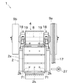
次に、図面を参照して本発明の実施の形態を説明する。図1は、本発明の一実施形態に係るジョークラッシャ1の全体的な構成を示す側面断面概略図である。図2は、ジョークラッシャ1の正面図である。図3は、ジョークラッシャ1のうちの歯間調節機構20のドグ(変位部材)24及び変位センサ25の周辺の構成を詳細に示す側面概略図である。図4は、変位センサ25の配置構成の概略図である。図5は、ジョークラッシャ1の電気的構成を示すブロック図である。
Next, an embodiment of the present invention will be described with reference to the drawings. FIG. 1 is a schematic side sectional view showing an overall configuration of a
図1及び図2に示すジョークラッシャ1は、本実施形態に係る揺動式破砕機である。ジョークラッシャ1は、岩石、鉱石、コンクリート廃材、アスファルト廃材、又は塊状炉滓等の破砕対象物を破砕する1次処理用設備として好適に用いられる。
The
図1に示すように、ジョークラッシャ1は、フレーム体2、偏心軸8、固定歯(第1歯)3、スイングジョー4、及び可動歯(第2歯)6等を備える。
As shown in FIG. 1, the
フレーム体2は、ジョークラッシャ1の外郭をなすものである。フレーム体2は、前壁2aと、1対の側壁2bと、当該側壁の一部をなす1対の側面ライナ2cと、を少なくとも備える。
The
1対の側壁2bの上部には、水平に配置された偏心軸8がベアリング18(図2を参照)を介して回転可能に支持されている。図2に示すように、偏心軸8は、両方の側壁2bを貫通して各側壁2bの外側に延びており、各側壁2bの外側に突出した軸端のうち一端には、プーリ9aが固定され、他端にはフライホイール9bが固定されている。プーリ9aには、ベルト17を介して電動モータ(駆動源)27の回転駆動力が伝達されるようになっている。
A horizontally arranged
固定歯3は、図1に示すようにフレーム体2の前壁2aの内壁面に固定される。本実施形態の固定歯3は、歯先が波状の形状に形成される。固定歯3は、破砕対象物に作用することにより摩耗する消耗品であるため、新しいものと容易に交換できるように構成されている。具体的には、両側の側面ライナ2c(図1及び図2を参照)を上方に引き抜き、前壁2aに設けられた複数の貫通孔2hにフレーム体2の外側から金属製の棒状の部材等を差し込んで叩くことにより、固定歯3を取り外すことができるようになっている。
As shown in FIG. 1, the fixing
スイングジョー4は、可動歯6を揺動可能に支持するものである。スイングジョー4は、1対の側壁2bの内壁面に沿うように設けられる。スイングジョー4の上部は、偏心軸8の長手方向中央部に形成された偏心部分に、ベアリング19を介して相対回転可能に支持される。この構成で、偏心軸8が回転すると、スイングジョー4の上部が、プーリ9aの回転中心を中心にして偏心量を半径とする円を描くように変位する。これにより、スイングジョー4を揺動させることができる。
The
可動歯6は、スイングジョー4に固定される。本実施形態の可動歯6は、歯先が波状の形状に形成される。可動歯6は、固定歯3に対面するようにスイングジョー4に取り付けられる。従って、スイングジョー4が揺動すると、可動歯6も固定歯3に対して揺動する。
The
図1に示すように、固定歯3と可動歯6との間には、破砕対象物を破砕するための空間である破砕室5が形成される。より詳細には、破砕室5は、フレーム体2の前壁2aの内壁面に固定されて1対の側面ライナ2cの間に配置される固定歯3と、当該固定歯3の後方で1対の側面ライナ2cの間に配置される可動歯6と、1対の側面ライナ2cと、によって4方を取り囲まれることにより形成される。可動歯6は、破砕室5が下方にいくに従って狭くなるように、傾斜して配置される。より具体的には、可動歯6は、固定歯3との間の距離が下方に向かうに従って近づくように、その前端部が後端部よりも低くなるように傾斜して配置される。
As shown in FIG. 1, a crushing
可動歯6は、破砕対象物に作用することにより摩耗する消耗品であるため、新しいものと容易に交換できるように構成されている。
Since the
破砕室5において、固定歯3及び可動歯6が破砕対象物に対して作用することによって、当該破砕対象物に圧縮力が加えられて当該破砕対象物が破砕(粗割り)されるようになっている。
In the crushing
スイングジョー4の下部には、前下がり状又は水平状となるように配置された細長い部材である引張ロッド16の先端部が連結されている。引張ロッド16は、その長手方向にスライド移動可能となるようにフレーム体2に支持されている。この引張ロッド16にはバネ10が配置されており、このバネ10は引張ロッド16を介して、スイングジョー4を前壁2aから離す向きに(言い換えれば、可動歯6を固定歯3から離す向きに)付勢する。この構成により、後に詳述するように、スイングジョー4の下部に設けられた前部トグルシート41にトグルプレート23の前端部が接触した状態を常に保っている。この結果、後述する油圧シリンダ(アクチュエータ)21の作動に連動してスイングジョー4の下部が変位するようになっている。
The lower end of the
また、本実施形態のジョークラッシャ1は、破砕対象物が破砕される部分(破砕室5)において温度が過剰に上昇した場合や油圧シリンダ21内の油圧が過剰に上昇した場合に、何らかの措置を講じられるようにするために必要な構成として、温度センサ(温度検出部)71、温度報知ランプ(報知部)72、及び変位報知ランプ73を備える。
Further, the
温度センサ71は、周囲の温度を検出することができるセンサであり、公知のあらゆる温度センサを適用することができる。本実施形態の温度センサ71は、固定歯3の背面と前壁2aの内壁面との間の空間において、固定歯3の背面に接触して設けられる。温度センサ71から延びる配線等は、前壁2aに固定歯3を外方から叩くため等に形成された貫通孔2h又は新たに設けられた貫通孔2hを通って外部の電子機器と接続されている。なお、図1に、温度センサ71から延びる配線等の例を2点鎖線で示してある。
The
図2に示すように、本実施形態の温度センサ71は、前壁2aの下部に3箇所設けられる貫通孔2hのうちの2つに対応して、左右一対に設けられる。これにより、破砕対象物がとりわけ滞留し易い破砕室5の下部において、固定歯3の温度を検出することができる。本実施形態では、温度センサ71の検出結果として、上記の2つの温度センサ71の検出値の平均値が採用される。
As shown in FIG. 2, the
また、図1及び図3に示すように、本実施形態のジョークラッシャ1は、固定歯3と可動歯6との間の間隔を調節するための歯間調節機構20として、油圧シリンダ21、油圧回路(不図示)、スライドブロック22、トグルプレート23、ドグ(変位部材)24、変位センサ25等を備える。
Further, as shown in FIGS. 1 and 3, the
本実施形態のアクチュエータとしての油圧シリンダ21は、シリンダと、ピストンと、を有する公知の単動式シリンダとして構成されている。
The
シリンダは、その軸線を傾斜させた状態で、フレーム体2に固定されている。詳細には、直方体形状の収容領域を有する収容体31が、その一側に形成される開口を前下方に向けた状態で、1対の側壁2bの間に固定的に設けられる。収容体31の後部には、リアフレーム32が固定される。油圧シリンダ21はこの収容体31の収容領域に収容されて、そのシリンダの後端面がリアフレーム32に固定された状態で設けられる。
The cylinder is fixed to the
ピストンにはシリンダロッドが固定される。このシリンダロッドはスイングジョー4に近づく向きに前下がり状に突出し、その先端がスライドブロック22に連結されている。油圧回路を介してシリンダ内に供給される作動油の油圧によって、油圧シリンダ21を伸ばす方向にピストンがスライド移動し、これによりスライドブロック22を前壁2aに近づく向きに変位させることができる。
A cylinder rod is fixed to the piston. The cylinder rod protrudes forward in a direction approaching the
上記の油圧回路は、油圧シリンダ21を作動させるためのものであり、公知の構成の油圧機器を組み合わせてなる。具体的には、この油圧回路は、作動油を貯留するタンク、タンク内の作動油を圧送する油圧ポンプの他、サクションフィルタ、チェック弁、リリーフ弁、電磁弁、及び圧力センサ等により構成される。この油圧回路によって、油圧シリンダ21のシリンダの中に作動油が適宜供給される。
The above-mentioned hydraulic circuit is for operating the
スライドブロック22は、油圧シリンダ21の軸線と平行な向きにスライド移動可能となるように、収容体31に支持されている。スライドブロック22には油圧シリンダ21のシリンダロッドの先端が連結されている。従って、油圧シリンダ21を伸ばす側に作動させることにより、スライドブロック22を、前壁2aに近づく側に変位させることができる。
The
トグルプレート23は、スイングジョー4とスライドブロック22との間に介在される板状の部材である。トグルプレート23は、スライドブロック22がスライドするのに連動して動作し、それにより固定歯3に対する距離を調節する動きをスイングジョー4(可動歯6)に付与する。トグルプレート23の前端部及び後端部は丸みを帯びた形状(例えば半円状)に形成され、トグルプレート23の前端部はスイングジョー4に対して滑り運動を行い、トグルプレート23の後端部はスライドブロック22に対して滑り運動を行うようになっている。
The
より具体的には、スイングジョー4の後部に前部トグルシート41が設けられている。この前部トグルシート41は、トグルプレート23の前端部が接触する滑らかな凹状面を有している。この前部トグルシート41の凹状面にトグルプレート23の前端部が接触しながら当該凹状面に沿って滑り運動を行う。
More specifically, a
また、スライドブロック22の前部に後部トグルシート33が設けられている。この後部トグルシート33は、トグルプレート23の後端部が接触する滑らかな凹状面を有している。この後部トグルシート33の凹状面にトグルプレート23の後端部が接触しながら当該凹状面に沿って滑り運動を行う。
Further, a
スイングジョー4の下部(厳密には、前部トグルシート41)は、上述したバネ10の付勢力が引張ロッド16を介して作用することによって、トグルプレート23の前端部に押し付けられている。また、このバネ10の付勢力を間接的に受けることにより、トグルプレート23の後端部がスライドブロック22(厳密には、後部トグルシート33)に押し付けられている。このように、トグルプレート23は、前部トグルシート41及び後部トグルシート33によって拘束され、前部トグルシート41及び後部トグルシート33から脱落しないようになっている。
The lower portion of the swing jaw 4 (strictly speaking, the front toggle sheet 41) is pressed against the front end portion of the
スライドブロック22の上部には、当該スライドブロック22(油圧シリンダ21のピストン)の動き(変位)を検出するための部材であるドグ24が設けられている。なお、収容体31の上部には、ドグ24を当該収容体31の外部に露出させて移動可能とするための溝が形成されている。
A
変位センサ25は、ドグ24の変位を検出するためのものである。本実施形態の変位センサ25は、図3に示すように、ドグ24の端部の位置を、前端の位置P1及び後端の位置P2の間で段階的に位置検出できるように、位置P1,P2に配置される2つの位置検出センサの間に数個の位置検出センサ(Pa,Pb,Pc,・・・)を含んで構成されている。この前端の位置P1及び後端の位置P2の間に配置される位置検出センサ(Pa,Pb,Pc,・・・)の個数は、ジョークラッシャ1の本体サイズや破砕対象物の大きさ、要求される破砕製品サイズによって適宜変更することができる。位置検出センサは何れも近接センサとして構成されており、収容体31の上部に固定された取付台25aに、フレーム25b等を介して取り付けられている。
The
図5に示すように、変位センサ25は、ジョークラッシャ1を制御するために設けられた制御部90に対し、電気的に接続されている。制御部90は、油圧回路の圧力センサ81の検出結果、及び温度センサ71の検出結果に応じて、歯間調節機構20、温度報知ランプ72、及び変位報知ランプ73を適宜動作させることにより、破砕対象物の適切な条件での破砕を促進することができる。言い換えれば、制御部90は、油圧シリンダ21の油圧、及び破砕が行われる部分(破砕室5)の温度の検出結果に応じて、固定歯3と可動歯6との間の間隔を段階的に調節したり、温度報知ランプ72や変位報知ランプ73を点灯・消灯したりして、適切な条件下での粗割りを実現する。
As shown in FIG. 5, the
制御部90は、CPU、ROM、RAM等を備えるコンピュータとして構成されている。前記ROMには、歯間調節機構20、温度報知ランプ72、及び変位報知ランプ73を、圧力センサ81の検出結果、及び温度センサ71の検出結果に基づいて動作させるための適宜のプログラム等が記憶されている。制御部90は、当該プログラム等に基づいて、前記の油圧回路に備えられる電磁弁85,86、温度報知ランプ72、及び変位報知ランプ73等に信号を送信することで、油圧シリンダ21、温度報知ランプ72、及び変位報知ランプ73等を適宜に動作させることが可能である。
The
また、図示しないが、ジョークラッシャ1の周囲にいる作業者等がこの歯間調節機構20を操作するための各種スイッチが備えられる制御盤が、ジョークラッシャ1のフレーム体2の外壁面、或いは当該ジョークラッシャ1を遠隔操作する通信端末等の適宜の場所に設けられる。
Further, although not shown, a control panel provided with various switches for an operator or the like around the
前端の位置P1において近接センサがドグ24を検出している場合、油圧シリンダ21が十分に伸びており、固定歯3と可動歯6との間隔が所定の間隔W1になっていることを意味する。本実施形態のジョークラッシャ1では、通常時(例えば、破砕開始直後)においては、固定歯3と可動歯6との間隔が上記の間隔W1となるように維持される。
When the proximity sensor detects the
破砕室5に破砕対象物が投入された場合、機械的な負荷が作用するため、油圧シリンダ21の圧力が上昇する。破砕が簡単であるか否かは一定でなく、破砕が困難な大型の破砕対象物が投入される場合も考えられるが、本実施形態のジョークラッシャ1では、油圧回路に設置された圧力センサ81の検出値が所定値に達した状態が所定時間以上継続する場合は、制御部90は、油圧回路において油圧シリンダ21に接続されている電磁弁85を開いて、作動油を逃がすように制御する。この結果、油圧シリンダ21の圧力が下がるとともに、油圧シリンダ21が縮む。即ち、前端の位置P1よりも後方に位置する近接センサPaが検出できる位置までドグ24が後退する。これにより、固定歯3と可動歯6との間隔が広げられる。この結果、破砕室5からの破砕対象物の排出を促しながら破砕を行うことができ、負荷の過大な上昇を回避することができる。
When the object to be crushed is put into the crushing
近接センサPaにおいてドグ24を検出した場合において、上記の圧力センサ81の検出値が上記の所定値以下である状態が所定時間以上継続する場合は、制御部90は、油圧ポンプに接続されている電磁弁86を開いて、油圧シリンダ21に作動油を供給するように制御する。この結果、油圧シリンダ21が延びるので、固定歯3と可動歯6との間隔が狭められ、所定の位置(前端の位置P1)に設定することができる。
When the
なお、前記のように固定歯3と可動歯6との間隔を広げたものの、圧力が十分に下がらず、圧力センサ81の検出値が依然として所定値に達した状態が所定時間以上継続する場合は、制御部90は、更に電磁弁85を開いて作動油を逃がし、固定歯3と可動歯6との間隔を更に広げて、破砕を継続する。このように、破砕が困難な場合、固定歯3と可動歯6との間隔を段階的に広げる処理が繰り返される。この歯の間隔を拡大する処理は、例えば、油圧シリンダ21が十分に縮んで、最終的には後端の位置P2の近接センサがドグ24を検出した状態となるまで行わせることができる。なお、後端の位置P2の近接センサがドグ24を検出した場合、ジョークラッシャ1の稼動が自動的に停止されるようになっている。
If the distance between the fixed
ところで、主に製鉄所等で発生する塊状炉滓をジョークラッシャ1により破砕する場合、塊状炉滓は鉄分を多く含むために靭性が高く、他の破砕対象物よりも破砕が困難である。従って、塊状炉滓を(特に、十分に冷却しない状態で)破砕室5に投入すると、破砕されずに長い時間滞留する場合があるため、破砕室5の内部が高温になることが多い。
By the way, when the massive furnace slag mainly generated in a steel mill or the like is crushed by the
破砕室5が高温になると、ジョークラッシャ1の稼動に対して様々な影響が生じることが考えられる。例えば、破砕対象物が直接的に接触する固定歯3及び可動歯6の耐久性が低下するおそれがある。また、破砕室5の熱がスイングジョー4を経由してベアリング18,19に伝達されると、高温になって潤滑性能が低下し、短寿命化等の原因となるおそれが生じる。
When the temperature of the crushing
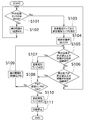
以下では、制御部90により行われる、圧力センサ81の検出結果、及び温度センサ71の検出結果に応じて固定歯3と可動歯6の間隔を調整したり警報を発したりする制御について、図6を参照して詳細に説明する。図6は、油圧シリンダ21の油圧、及び破砕される部分の温度の検出結果に応じて、制御部90で行われる処理を示すフローチャートである。
In the following, FIG. 6 relates to a control performed by the
なお、油圧回路が備える圧力センサ81の検出結果は、油圧シリンダ21のシリンダ内(作動油が供給される空間内)の油圧を実質的に表すものであるため、以下の説明においては、この検出結果を「油圧シリンダ21内の油圧」と称する場合がある。また、温度センサ71の検出結果は、破砕対象物の破砕が行われる部分(より具体的には、本実施形態では破砕室5を構成する部材の1つである固定歯3)における温度を表すものであるため、以下の説明においては、この検出結果を「破砕される部分の温度」と称する場合がある。
Since the detection result of the
初めに、制御部90は、前端の位置P1の近接センサのみがドグ24を検出してONとなっているか否かを判断する(ステップS101)。
First, the
前端の位置P1の近接センサのみがONではない場合(ステップS101、No)、固定歯3と可動歯6との間隔が、所定の間隔W1よりも広がっていることを意味する。そこで、制御部90は、油圧ポンプに接続されている電磁弁86を開いて、油圧シリンダ21に圧力を供給し、油圧シリンダ21を伸ばして固定歯3と可動歯6との間隔を1段階狭める(ステップS102)。これにより、固定歯3と可動歯6との間隔を元の状態に近づけることができる。その後、ステップS101に戻る。
When only the proximity sensor at the front end position P1 is not ON (step S101, No), it means that the distance between the fixed
一方、ステップS101での判断の結果、前端の位置P1の近接センサのみがONである場合(ステップS101、Yes)、制御部90は、温度報知ランプ72、変位報知ランプ73が点灯している場合はともに消灯させ(ステップS103)、破砕対象物の投入の状態が良好である旨(即ち、追加投入してもよい旨)を周囲に報知する(ステップS104)。このとき制御部90は、温度センサ71の検出値により取得される破砕される部分の温度が所定値以上である状態が所定時間継続しているか否かを判断する(ステップS105)。
On the other hand, as a result of the determination in step S101, when only the proximity sensor at the front end position P1 is ON (step S101, Yes), the
温度センサ71が検出した温度が所定値以上である状態が所定時間継続している場合(ステップS105、Yes)、制御部90は、温度報知ランプ72を点灯させて、破砕される部分の温度が相当に高い旨を周囲に報知する(ステップS107)。これにより、周囲の作業者は状況を正しく把握して、例えば、破砕対象物の破砕室5への追加投入を一時的に中断したり、破砕室5から排出された破砕対象物に水を掛けて強制的に冷却したりする等の対応をとることができる。その後、制御部90は、後端の位置P2の近接センサがドグ24を検出してONとなっているか否かを判断する(ステップS108)。
When the state in which the temperature detected by the
温度センサ71が検出した温度が所定値未満である場合、又は、所定値以上であるもののその状態が所定時間継続していない場合(ステップS105、No)、制御部90は、油圧回路において油圧シリンダ21に接続されている圧力センサ81の検出値が所定値以上である状態が所定時間継続しているか否かを判断する(ステップS106)。
When the temperature detected by the
圧力センサ81が検出した圧力が所定値以上である状態が所定時間継続している場合(ステップS106、Yes)、制御部90は、上記と同様に、後端の位置P2の近接センサがドグ24を検出してONとなっているか否かを判断する(ステップS108)。
When the state in which the pressure detected by the
圧力センサ81が検出した圧力が所定値未満である場合、又は、所定値以上であるもののその状態が所定時間継続していない場合(ステップS106、No)、正常な状態であるため、ステップS101に戻る。
If the pressure detected by the
後端の位置P2の近接センサがONである場合(ステップS108、Yes)、制御部90は、変位報知ランプ73を点灯させて、固定歯3と可動歯6との間隔が最大の状態(異常に開いている状態)で、これ以上の間隔は開かない旨を周囲に報知する(ステップS110)。これにより、周囲の作業者は状況を正しく把握して、例えば、破砕対象物の破砕室5への破砕対象物の新たな投入を停止する等の対応を取ることができる。
When the proximity sensor at the rear end position P2 is ON (step S108, Yes), the
その後、制御部90は、電動モータ27を停止させることによりジョークラッシャ1の運転を自動的に停止させて(ステップS111)、一連の処理を終了する。
After that, the
ステップS108の判断において後端の位置P2の近接センサがOFFである場合(ステップS108、No)、制御部90は、油圧シリンダ21に接続される電磁弁85を開くことにより油圧シリンダ21の圧油を逃がし、油圧シリンダ21を縮めて固定歯3と可動歯6との間隔を1段階広げる(ステップS109)。これにより、高温になっている破砕が困難な破砕対象物について、破砕室5からの排出を促すことができる。その後、ステップS105に戻る。
When the proximity sensor at the rear end position P2 is OFF in the determination in step S108 (step S108, No), the
以上に示した処理の流れにより、油圧の値及び破砕される部分の温度の値に応じて破砕室5の出口の間隙を適宜変更することにより、ジョークラッシャ1の連続的な稼動が実現されている。また、温度が異常に高い場合には、温度報知ランプ72により周囲の作業者に知らせて、適切な対応を行わせることができる。更に、油圧シリンダ21の圧力が異常に高くかつそれ以上固定歯3と可動歯6との間隔を広げられない場合には、変位報知ランプ73により周囲の作業作業者に知らせて、適切な対応を行わせることができる。
According to the processing flow shown above, the
以上に説明したように、本実施形態のジョークラッシャ(揺動式破砕機)1は、固定歯(第1歯)3と、可動歯(第2歯)6と、温度センサ(温度検出部)71と、を備える。可動歯6は、揺動可能に設けられて固定歯3との間に破砕室5を形成する。温度センサ71は、破砕室5を構成する部材の1つである固定歯3の温度を検出する。
As described above, the jaw crusher (oscillating crusher) 1 of the present embodiment includes a fixed tooth (first tooth) 3, a movable tooth (second tooth) 6, and a temperature sensor (temperature detection unit). 71 and. The
これにより、破砕対象物が破砕される部分における温度上昇を温度センサ71で検出して、何らかの対応を行うことが可能になる。従って、高温下で破砕が続けられて温度が更に上昇してしまい、固定歯3や可動歯6の性能に悪影響が及ぶことを防止することができる。具体的には、例えば固定歯3や可動歯6の摩耗速度・硬度等に高温による悪影響が及ぶことを抑制できる。また、固定歯3や可動歯6の周囲の部材に熱が伝わって性能・寿命に悪影響が及ぶことも防止することができる。例えば本実施形態の場合、可動歯6の熱がスイングジョー4等を介してベアリング18,19に伝わることが考えられるが、温度センサ71で破砕される部分の温度を得るとともに図6に示した制御が行われるので、ベアリング18の性能・寿命に悪影響が及ぶことを抑制できる。
As a result, the
また、本実施形態のジョークラッシャ1は、油圧シリンダ(アクチュエータ)21と、制御部90と、を備える。油圧シリンダ21は、固定歯3と可動歯6との間の間隔を変化させることが可能である。制御部90は、温度センサ71の検出結果が所定温度以上である場合(図6のステップS105、Yes)に、固定歯3と可動歯6との間の間隔を拡大するように油圧シリンダ21を制御する(図6のステップS109)。
Further, the
これにより、破砕室5が高温となった場合に、破砕対象物の排出を自動的に促して、温度の更なる上昇を防止することができる。
As a result, when the temperature of the crushing
また、本実施形態のジョークラッシャ1は、温度センサ71の検出結果が所定温度以上である場合(図6のステップS105、Yes)に報知する温度報知ランプ(報知部)72を備える。
Further, the
これにより、破砕室5が高温になっている場合に例えば温度報知ランプ72を点灯することにより周囲の作業者に報知することができ(図6のステップS107)、それにより、破砕物の追加投入を抑制したり、排出された被処理物の冷却を促したりすることができる。
As a result, when the crushing
また、本実施形態のジョークラッシャ1においては、温度センサ71は、固定歯3の温度を検出する。
Further, in the
これにより、靭性の高い破砕対象物(具体的には、例えば鉄分を多く含む塊状炉滓等)が高温の状態で固定歯3に接触/付着することによる温度上昇を、温度センサ71によって適切に検出することができる。
As a result, the
また、本実施形態のジョークラッシャ1においては、前記第1歯は固定歯3として構成される。前記第2歯は可動歯6として構成される。温度センサ71は、固定歯3の温度を検出する。
Further, in the
これにより、温度センサ71に加わる振動を抑制することができる。
As a result, the vibration applied to the
また、本実施形態のジョークラッシャ1においては、破砕室5は、下方にいくに従って狭くなるように形成される。温度センサ71は、破砕室5の下部において、当該破砕室5を構成する部材の1つである固定歯3の温度を検出する。
Further, in the
これにより、破砕対象物が破砕室5の下部で滞留することで温度が上昇し易くなることを等慮して、破砕対象物の破砕に伴う温度上昇を効果的に検出することができる。
As a result, the temperature rise associated with the crushing of the crushed object can be effectively detected in consideration of the fact that the temperature of the crushed object tends to rise due to the retention of the crushed object in the lower part of the crushing
また、本実施形態のジョークラッシャ1においては、アクチュエータは、作動油の圧力を増加させることにより固定歯3と可動歯6との間の間隔を狭める一方、作動油の圧力を減少させることにより固定歯3と可動歯6との間の間隔を広げることが可能な油圧シリンダ(油圧アクチュエータ)21である。このジョークラッシャ1は、油圧シリンダ21の作動油の圧力を検出する圧力センサ(作動圧力検出部)81を備える。制御部90は、圧力センサ81の検出結果が所定圧力以上である場合に、油圧シリンダ21の作動油の圧力を減少させて固定歯3と可動歯6との間隔を広げる制御を行う。
Further, in the
これにより、固定歯3と可動歯6との間に破砕が困難な破砕対象物が噛み込む等して油圧シリンダ21の作動油の圧力が高まった場合に、作動油の圧力を減少させて固定歯3と可動歯6との間の間隔を広げる制御を行うことができ、破砕対象物の排出を促しながら破砕を行うことができる。これにより、負荷の過大な上昇を回避することができる。また、破砕室5において大きな摩擦力が働くことによる過剰な温度上昇も解消することができる。
As a result, when the pressure of the hydraulic oil of the
また、本実施形態のジョークラッシャ1は、ドグ24と、変位センサ25と、を備える。ドグ24は、油圧シリンダ21の作動状態に応じて変位する。変位センサ25は、ドグ24の複数段階の位置のそれぞれを検出可能である。制御部90は、温度センサ71の検出結果が所定温度以上である場合に、ドグ24の位置を、変位センサ25が検出可能な隣接する次の位置まで変位させるように油圧シリンダ21を作動させることにより、固定歯3と可動歯6との間隔を複数段階のうちの次の段階にまで拡大する。
Further, the
これにより、破砕が行われる部分や破砕対象物の温度が過剰に高温となった場合には、段階的に固定歯3と可動歯6との間隔を広げることにより、それ以上に高温となることを抑制しながら破砕を継続することができる。よって、様々な大きさの破砕対象物を適切な条件で破砕することができる。
As a result, when the temperature of the part to be crushed or the object to be crushed becomes excessively high, the temperature becomes higher than that by gradually widening the distance between the fixed
また、本実施形態の破砕方法においては、固定歯(第1歯)3と、可動歯(第2歯)6と、温度センサ(温度検出部)71と、を備えるジョークラッシャ(揺動式破砕機)1によって破砕対象物を破砕する。可動歯6は、揺動可能に設けられて固定歯3との間に破砕室5を形成する。温度センサ71は、破砕室5を構成する部材又は破砕室5に投入された破砕対象物の温度を検出する。温度センサ71の検出結果が所定温度未満の場合には、固定歯3と可動歯6との間隔を所定の間隔W1に維持し、又は当該所定の間隔W1に近づくように狭める。温度センサ71の検出結果が所定温度以上の場合には、固定歯3と可動歯6との間隔を前記所定の間隔W1よりも広げる。
Further, in the crushing method of the present embodiment, a jaw crusher (swing type crusher) including a fixed tooth (first tooth) 3, a movable tooth (second tooth) 6, and a temperature sensor (temperature detection unit) 71 is provided. Machine) 1 crushes the object to be crushed. The
これにより、破砕室5の温度が適正な温度に保たれている場合には、固定歯3と可動歯6との間隔を破砕に適した間隔W1にして破砕を継続的に行うことができる。一方、破砕室5の温度が過剰に高温となっている場合には、固定歯3と可動歯6との間隔を広げて、破砕対象物の排出を促すことができ、それ以上破砕室が高温となってしまう事態を回避することができる。
As a result, when the temperature of the crushing
以上に本発明の好適な実施の形態を説明したが、上記の構成は例えば以下のように変更することができる。 Although the preferred embodiment of the present invention has been described above, the above configuration can be changed as follows, for example.
上記の実施形態では、温度検出部としての温度センサ71は、破砕室5を構成する部材の1つである固定歯3の温度を検出するものとした。しかしながら、これに限るものではなく、温度検出部を、破砕室5を構成する他の部材(具体的には、例えば可動歯6、或いは側面ライナ2c)の温度を検出するものとしてもよい。或いは、これらに代えて、例えば温度検出部をサーモグラフィとして構成し、破砕室5に投入された破砕対象物の温度を検出するものとしてもよい。
In the above embodiment, the
仮に温度検出部を第1歯又は第2歯の少なくとも何れかの温度を検出する構成とした場合、当該温度検出部の取付位置は、第1歯又は第2歯の背面に限るものではない。即ち、例えば温度検出部を第1歯の内部に埋め込まれるもの、或いはネジ込まれるものとしてもよい。 If the temperature detection unit is configured to detect the temperature of at least one of the first tooth and the second tooth, the mounting position of the temperature detection unit is not limited to the back surface of the first tooth or the second tooth. That is, for example, the temperature detection unit may be embedded in the first tooth or screwed into the first tooth.
温度検出部は、固定歯(第1歯)3及び可動歯(第2歯)6の両方の温度を検出するものとして構成してもよい。その場合、固定歯3の温度の検出値と可動歯6の温度の検出値との平均値を検出結果として採用してもよいし、或いは、複数の歯3,6の温度の検出値のうちの高い方を検出結果として採用してもよい。
The temperature detection unit may be configured to detect the temperatures of both the fixed tooth (first tooth) 3 and the movable tooth (second tooth) 6. In that case, the average value of the temperature detection value of the fixed
上記の実施形態では、固定歯(第1歯)3と可動歯(第2歯)6との間隔を変化させるアクチュエータは、油圧シリンダ21であるものとしたが、これに代えて他のアクチュエータを適用することもできる。例えば、エアシリンダ等の油圧以外の力で作動するシリンダを適用することもできるし、或いは複数のクサビ部材同士がスライドすることによりスライドブロック22の位置が変位される構成の駆動装置を適用することもできる。
In the above embodiment, the actuator for changing the distance between the fixed tooth (first tooth) 3 and the movable tooth (second tooth) 6 is a
上記の実施形態では、報知部は点灯する温度報知ランプ72及び変位報知ランプ73であるものとしたが、これに限るものではない。例えばこれに代えて、報知部を、アラーム音を発する装置等とすることもできる。即ち、報知部は、作業者の視覚に訴えるものであっても、聴覚に訴えるものでも、何れであってもよい。また、例えば作業者がジョークラッシャ1を操作するための通信端末に報知部が備えられるものとしてもよい。
In the above embodiment, the notification unit is a
上記の実施形態では、変位センサ25は、図4に示すように、前端の位置P1及び後端の位置P2の間で段階的に位置検出する非接触式の近接センサ(Pa,Pb,・・・)であるものとしたが、これに限るものではない。即ち、変位センサ25は、ドグ24に接触することによりその位置を検出する接触式のセンサ(例えば、リミットスイッチ)等により構成してもよい。
In the above embodiment, as shown in FIG. 4, the
上記の実施形態では、固定歯(第1歯)3は固定的に設けられ、可動歯(第2歯)6は当該固定歯3に対して揺動可能に設けられるものとした。しかしながら、これに限るものではなく、例えばこれに代えて、第2歯を固定的に設けるものとし、第1歯を揺動可能に設けるものとしてもよい。或いは、これらに代えて、第1歯及び第2歯の両方が揺動可能ないわゆる両あご式の構成としてもよい。
In the above embodiment, the fixed tooth (first tooth) 3 is provided fixedly, and the movable tooth (second tooth) 6 is provided so as to be swingable with respect to the fixed
上記の実施形態では、揺動式破砕機はジョークラッシャ1であるものとしたが、必ずしもこれに限るものではなく、これに代えてスプリッタ等としてもよい。
In the above embodiment, the rocking crusher is a
上記の実施形態では、固定歯3と可動歯6との間の間隔は段階的に変更(調節)されるものとしたが、必ずしもこれに限るものではなく、これらの歯先の間隔が連続的に変更(調整)されるものとしてもよい。
In the above embodiment, the distance between the fixed
1 ジョークラッシャ(揺動式破砕機)
3 固定歯(第1歯)
4 スイングジョー
5 破砕室
6 可動歯(第2歯)
18 ベアリング
19 ベアリング
21 油圧シリンダ(アクチュエータ)
71 温度センサ(温度検出部)
72 温度報知ランプ(報知部)
90 制御部
1 Joe crusher (oscillating crusher)
3 Fixed tooth (1st tooth)
4
18
71 Temperature sensor (Temperature detector)
72 Temperature notification lamp (notification unit)
90 Control unit
Claims (6)
揺動可能に設けられて前記第1歯との間に破砕室を形成する第2歯と、
前記第1歯若しくは前記第2歯のうち、前記破砕室に投入された破砕対象物に作用する部分の温度、又は、前記破砕室に投入された破砕対象物の温度を検出する温度検出部と、
前記第1歯と前記第2歯との間の間隔を変化させることが可能なアクチュエータと、
前記温度検出部の検出結果が所定温度以上である場合に、前記第1歯と前記第2歯との間の間隔を拡大するように前記アクチュエータを制御する制御部と、
を備えることを特徴とする揺動式破砕機。 1st tooth and
A second tooth that is swingably provided and forms a crushing chamber between the first tooth and the second tooth.
A temperature detection unit that detects the temperature of the portion of the first tooth or the second tooth that acts on the crushing object put into the crushing chamber, or the temperature of the crushing object put into the crushing chamber. ,
An actuator capable of changing the distance between the first tooth and the second tooth,
A control unit that controls the actuator so as to increase the distance between the first tooth and the second tooth when the detection result of the temperature detection unit is equal to or higher than a predetermined temperature.
A swinging crusher characterized by being equipped with.
前記温度検出部の検出結果が所定温度以上である場合に報知する報知部を備えることを特徴とする揺動式破砕機。 The rocking crusher according to claim 1.
A swing-type crusher including a notification unit that notifies when the detection result of the temperature detection unit is equal to or higher than a predetermined temperature.
前記第1歯は固定歯として構成され、
前記第2歯は可動歯として構成され、
前記温度検出部は、前記第1歯のうち、前記破砕対象物に作用する部分の温度を検出することを特徴とする揺動式破砕機。 The rocking crusher according to claim 1 or 2.
The first tooth is configured as a fixed tooth.
The second tooth is configured as a movable tooth.
The temperature detection unit is a swing-type crusher characterized by detecting the temperature of a portion of the first tooth that acts on the object to be crushed.
前記アクチュエータは、作動油の圧力を増加させることにより前記第1歯と前記第2歯との間隔を狭める一方、作動油の圧力を減少させることにより前記第1歯と前記第2歯との間隔を広げることが可能な油圧アクチュエータであり、
前記油圧アクチュエータの作動油の圧力を検出する作動圧力検出部を備え、
前記制御部は、前記作動圧力検出部の検出結果が所定圧力以上である場合に、前記油圧アクチュエータの作動油の圧力を減少させて前記第1歯と前記第2歯との間隔を広げる制御を行うことを特徴とする揺動式破砕機。 The rocking crusher according to any one of claims 1 to 3.
The actuator narrows the distance between the first tooth and the second tooth by increasing the pressure of the hydraulic oil, while the distance between the first tooth and the second tooth is reduced by reducing the pressure of the hydraulic oil. It is a hydraulic actuator that can expand
A working pressure detecting unit for detecting the pressure of the hydraulic oil of the hydraulic actuator is provided.
The control unit controls to reduce the pressure of the hydraulic oil of the hydraulic actuator to widen the distance between the first tooth and the second tooth when the detection result of the operating pressure detecting unit is equal to or higher than a predetermined pressure. A swing-type crusher characterized by performing.
前記アクチュエータの作動状態に応じて変位する変位部材と、
前記変位部材の複数段階の位置のそれぞれを検出可能な変位検出部と、
を備え、
前記制御部は、
前記温度検出部の検出結果が所定温度以上である場合に、前記変位部材の位置を前記変位検出部が検出可能な隣接する次の位置まで変位させるように前記アクチュエータを作動させて、前記第1歯と前記第2歯との間隔を複数段階のうちの次の段階にまで拡大することを特徴とする揺動式破砕機。 The rocking crusher according to any one of claims 1 to 4.
A displacement member that displaces according to the operating state of the actuator, and
A displacement detection unit that can detect each of the positions of a plurality of stages of the displacement member,
With
The control unit
When the detection result of the temperature detection unit is equal to or higher than a predetermined temperature, the actuator is operated so as to displace the position of the displacement member to an adjacent next position that can be detected by the displacement detection unit, and the first. A swing-type crusher characterized in that the distance between a tooth and the second tooth is expanded to the next stage among a plurality of stages.
揺動可能に設けられて前記第1歯との間に破砕室を形成する第2歯と、
前記第1歯若しくは前記第2歯のうち、前記破砕室に投入された破砕対象物に作用する部分の温度、又は、前記破砕室に投入された破砕対象物の温度を検出する温度検出部と、
を備える揺動式破砕機によって破砕対象物を破砕する破砕方法であって、
前記温度検出部の検出結果が所定温度未満の場合には、前記第1歯と前記第2歯との間隔を所定の間隔に維持し、又は当該所定の間隔に近づくように狭め、
前記温度検出部の検出結果が所定温度以上の場合には、前記第1歯と第2歯との間隔を前記所定の間隔よりも広げることを特徴とする破砕方法。 1st tooth and
A second tooth that is swingably provided and forms a crushing chamber between the first tooth and the second tooth.
A temperature detection unit that detects the temperature of the portion of the first tooth or the second tooth that acts on the crushing object put into the crushing chamber, or the temperature of the crushing object put into the crushing chamber. ,
It is a crushing method for crushing an object to be crushed by a swinging crusher equipped with.
When the detection result of the temperature detection unit is lower than the predetermined temperature, the distance between the first tooth and the second tooth is maintained at a predetermined distance or narrowed so as to approach the predetermined distance.
A crushing method characterized in that when the detection result of the temperature detection unit is equal to or higher than a predetermined temperature, the distance between the first tooth and the second tooth is wider than the predetermined distance.
Priority Applications (2)
| Application Number | Priority Date | Filing Date | Title |
|---|---|---|---|
| JP2016256387A JP6963384B2 (en) | 2016-12-28 | 2016-12-28 | Swing type crusher and crushing method |
| PCT/JP2017/045579 WO2018123740A1 (en) | 2016-12-28 | 2017-12-19 | Rocking crusher and crushing method |
Applications Claiming Priority (1)
| Application Number | Priority Date | Filing Date | Title |
|---|---|---|---|
| JP2016256387A JP6963384B2 (en) | 2016-12-28 | 2016-12-28 | Swing type crusher and crushing method |
Publications (2)
| Publication Number | Publication Date |
|---|---|
| JP2018108541A JP2018108541A (en) | 2018-07-12 |
| JP6963384B2 true JP6963384B2 (en) | 2021-11-10 |
Family
ID=62707506
Family Applications (1)
| Application Number | Title | Priority Date | Filing Date |
|---|---|---|---|
| JP2016256387A Active JP6963384B2 (en) | 2016-12-28 | 2016-12-28 | Swing type crusher and crushing method |
Country Status (2)
| Country | Link |
|---|---|
| JP (1) | JP6963384B2 (en) |
| WO (1) | WO2018123740A1 (en) |
Families Citing this family (5)
| Publication number | Priority date | Publication date | Assignee | Title |
|---|---|---|---|---|
| CN108465508A (en) * | 2018-07-06 | 2018-08-31 | 太仓市鼎祥五金制品厂 | A kind of jaw crusher with warning function |
| CN110193398A (en) * | 2019-06-18 | 2019-09-03 | 河南中誉鼎力智能装备有限公司 | A kind of dynamic jaw stroke adjuster and its jaw crusher |
| CN110193397B (en) * | 2019-06-18 | 2021-11-26 | 河南中誉鼎力智能装备有限公司 | Intelligent control system for jaw crusher and jaw crusher thereof |
| CN111185259B (en) * | 2019-11-29 | 2021-04-27 | 靖州县新球实业有限责任公司 | Crusher capable of adjusting jaw plate interval |
| CN111468214B (en) * | 2020-05-13 | 2022-03-01 | 山东联邦重工有限公司 | Rocker structure for adjusting jaw crusher |
Family Cites Families (9)
| Publication number | Priority date | Publication date | Assignee | Title |
|---|---|---|---|---|
| JPS49130558A (en) * | 1973-04-23 | 1974-12-13 | ||
| CH619157A5 (en) * | 1976-07-16 | 1980-09-15 | Buehler Ag Geb | |
| JPS6261651A (en) * | 1985-09-10 | 1987-03-18 | 川崎重工業株式会社 | Automatic operation control method of rocking type rough crusher |
| JP2570057B2 (en) * | 1992-04-15 | 1997-01-08 | 株式会社栗本鐵工所 | Jaw crusher |
| JP4208992B2 (en) * | 1998-05-20 | 2009-01-14 | 株式会社中山鉄工所 | Jaw crusher |
| CN105473232A (en) * | 2013-06-03 | 2016-04-06 | 布勒股份公司 | Roller pair, measuring device, product-processing installation, and method |
| US9718062B2 (en) * | 2013-09-09 | 2017-08-01 | Mclanahan Corporation | Crusher with adjustable closed side setting |
| EP2868379B1 (en) * | 2013-11-01 | 2016-02-03 | Sandvik Intellectual Property AB | Method and system for controlling a jaw crusher |
| CN210965263U (en) * | 2019-11-02 | 2020-07-10 | 柳州市昊宇机械有限公司 | Movable cone crusher and intelligent control structure |
-
2016
- 2016-12-28 JP JP2016256387A patent/JP6963384B2/en active Active
-
2017
- 2017-12-19 WO PCT/JP2017/045579 patent/WO2018123740A1/en active Application Filing
Also Published As
| Publication number | Publication date |
|---|---|
| WO2018123740A1 (en) | 2018-07-05 |
| JP2018108541A (en) | 2018-07-12 |
Similar Documents
| Publication | Publication Date | Title |
|---|---|---|
| JP6963384B2 (en) | Swing type crusher and crushing method | |
| US9718062B2 (en) | Crusher with adjustable closed side setting | |
| KR101659499B1 (en) | Bucket-type jaw crusher | |
| CN105283251B (en) | Method of operating a crusher, crushing system and crushing station | |
| US11103874B2 (en) | Gyratory crusher hydraulic pressure relief valve | |
| JP2009297591A (en) | Jaw crusher | |
| WO2015062824A1 (en) | Method and system for controlling a jaw crusher | |
| WO2002077476A1 (en) | Method for monitoring condition of bearings of a crusher, and a crusher | |
| EP3068537B1 (en) | Jaw crusher, crushing plant and crushing method | |
| WO2002034393A1 (en) | Jaw crusher unit | |
| JP7062351B2 (en) | Crusher | |
| JP5668903B2 (en) | Vertical crusher | |
| EP1984117B1 (en) | A method for controlling a crusher and a crusher | |
| JP5660225B2 (en) | Vertical roller mill | |
| JP4093517B2 (en) | Tooth gap adjustment device for crushing device and adjustment method thereof | |
| JP5668902B2 (en) | Vertical crusher | |
| JP6884976B2 (en) | Joe crusher and its control method | |
| JP2570057B2 (en) | Jaw crusher | |
| JP2022140398A (en) | Crusher, speed control method of crushing device, and speed control program of crushing device | |
| JP5747451B2 (en) | Slug crusher | |
| WO2024080324A1 (en) | Gyratory crusher, and control device and control method for same | |
| JP2007125495A (en) | Jaw crusher | |
| KR101322245B1 (en) | Apparatus for protecting crash of repulsion plate in crusher | |
| RU2231387C2 (en) | Single-roll toothed grinder | |
| JPWO2019097998A1 (en) | Vertical crusher and crushing roller pressure control method for vertical crusher |
Legal Events
| Date | Code | Title | Description |
|---|---|---|---|
| A621 | Written request for application examination |
Free format text: JAPANESE INTERMEDIATE CODE: A621 Effective date: 20191223 |
|
| A131 | Notification of reasons for refusal |
Free format text: JAPANESE INTERMEDIATE CODE: A131 Effective date: 20201126 |
|
| A521 | Request for written amendment filed |
Free format text: JAPANESE INTERMEDIATE CODE: A523 Effective date: 20210125 |
|
| A131 | Notification of reasons for refusal |
Free format text: JAPANESE INTERMEDIATE CODE: A131 Effective date: 20210621 |
|
| A521 | Request for written amendment filed |
Free format text: JAPANESE INTERMEDIATE CODE: A523 Effective date: 20210820 |
|
| TRDD | Decision of grant or rejection written | ||
| A01 | Written decision to grant a patent or to grant a registration (utility model) |
Free format text: JAPANESE INTERMEDIATE CODE: A01 Effective date: 20211005 |
|
| A61 | First payment of annual fees (during grant procedure) |
Free format text: JAPANESE INTERMEDIATE CODE: A61 Effective date: 20211015 |
|
| R150 | Certificate of patent or registration of utility model |
Ref document number: 6963384 Country of ref document: JP Free format text: JAPANESE INTERMEDIATE CODE: R150 |
|
| R250 | Receipt of annual fees |
Free format text: JAPANESE INTERMEDIATE CODE: R250 |