JP6962811B2 - Flange separation prevention device - Google Patents

Flange separation prevention device Download PDF

Info

Publication number
JP6962811B2
JP6962811B2 JP2017248956A JP2017248956A JP6962811B2 JP 6962811 B2 JP6962811 B2 JP 6962811B2 JP 2017248956 A JP2017248956 A JP 2017248956A JP 2017248956 A JP2017248956 A JP 2017248956A JP 6962811 B2 JP6962811 B2 JP 6962811B2
Authority
JP
Japan
Prior art keywords
bolt
prevention device
holding body
narrow
separation prevention
Prior art date
Legal status (The legal status is an assumption and is not a legal conclusion. Google has not performed a legal analysis and makes no representation as to the accuracy of the status listed.)
Active
Application number
JP2017248956A
Other languages
Japanese (ja)
Other versions
JP2019113155A (en
Inventor
直樹 金田
太郎 笠原
Current Assignee (The listed assignees may be inaccurate. Google has not performed a legal analysis and makes no representation or warranty as to the accuracy of the list.)
Cosmo Koki Co Ltd
Original Assignee
Cosmo Koki Co Ltd
Priority date (The priority date is an assumption and is not a legal conclusion. Google has not performed a legal analysis and makes no representation as to the accuracy of the date listed.)
Filing date
Publication date
Application filed by Cosmo Koki Co Ltd filed Critical Cosmo Koki Co Ltd
Priority to JP2017248956A priority Critical patent/JP6962811B2/en
Publication of JP2019113155A publication Critical patent/JP2019113155A/en
Priority to JP2021166615A priority patent/JP7161018B2/en
Application granted granted Critical
Publication of JP6962811B2 publication Critical patent/JP6962811B2/en
Active legal-status Critical Current
Anticipated expiration legal-status Critical

Links

Images

Description

本発明は、対向した一対のフランジの離間を防止するフランジ離間防止装置に関する。 The present invention relates to a flange separation prevention device that prevents a pair of facing flanges from being separated.

従来、フランジ接続された管路構成部材同士の接続強度を高めるために用いられるフランジ離間防止装置は、一対のフランジの管軸方向外側に配置される狭持片部を有する狭持枠と、一方の狭持片部に取付けられ、フランジを流体管の管軸方向に押圧するボルトと、を備え、前記ボルトと他方の狭持片部とで一対のフランジを狭持するものがあった(例えば、特許文献1参照)。 Conventionally, a flange separation prevention device used for increasing the connection strength between flange-connected pipeline constituent members is a narrow-holding frame having a narrow-holding piece portion arranged outside in the pipe axis direction of a pair of flanges, and one of them. There is a bolt that is attached to the narrow holding piece portion of the above and presses the flange in the direction of the pipe axis of the fluid pipe, and the bolt and the other narrow holding piece portion hold a pair of flanges (for example). , Patent Document 1).

また、一対のフランジを管軸方向に挟むように2つの狭持部材を配置し、一対のフランジの外側の位置で2つの狭持部材をボルトにより管軸方向に接続することで一対のフランジを狭持するものがあった(例えば、特許文献2参照)。 Further, two holding members are arranged so as to sandwich the pair of flanges in the pipe axis direction, and the pair of flanges are connected by bolts at positions outside the pair of flanges in the pipe axis direction. There was something that was narrowed down (see, for example, Patent Document 2).

しかしながら、これら特許文献1及び特許文献2に示されるフランジ離間防止装置は、管路構成部材の管軸方向にボルトを締め込むことで一対のフランジを狭持する構成であることから、流体管の管軸方向に補修弁等の構成部材が配設されている場合、前記構成部材に干渉してボルトを締め込む作業を行うことができないことがあった。また、特許文献2については、一対のフランジの外側の位置で2つの挟持部材をボルトで締め付けるため、これらの挟持部材同士の内側部分が開き、充分に挟持できない虞があった。 However, since the flange separation prevention devices shown in Patent Documents 1 and 2 have a configuration in which a pair of flanges are narrowed by tightening bolts in the pipe axial direction of the pipeline constituent member, the fluid pipe has a structure. When a component such as a repair valve is arranged in the pipe axis direction, it may not be possible to perform the work of tightening the bolt by interfering with the component. Further, in Patent Document 2, since the two sandwiching members are tightened with bolts at positions outside the pair of flanges, there is a risk that the inner portions of the sandwiching members will open and the sandwiching members cannot be sufficiently sandwiched.

そこで、狭持枠を一対のフランジに取付けた状態で該一対のフランジの径方向に進退可能なボルトと、該ボルトにより押圧される介在部材と、を備え、ボルトを一対のフランジの外径方向から内径方向に進行させることで径方向に生じる押圧力を、該介在部材が有する傾斜面により管軸方向の押圧力に変換し、該介在部材と前記狭持枠の狭持片部とで一対のフランジを管軸方向に狭持するものが開発されている(例えば、特許文献3参照)。 Therefore, a bolt capable of advancing and retreating in the radial direction of the pair of flanges with the narrow holding frame attached to the pair of flanges and an intervening member pressed by the bolt are provided, and the bolt is provided in the outer radial direction of the pair of flanges. The pressing force generated in the radial direction by advancing in the inner diameter direction is converted into the pressing force in the pipe axis direction by the inclined surface of the intervening member, and the intervening member and the narrowing piece portion of the holding frame form a pair. A flange has been developed that holds the flange in the pipe axis direction (see, for example, Patent Document 3).

実開昭63−103086号公報(第1頁、第1図)Jikkai Sho 63-103086 (Page 1, Fig. 1) 特開2016−125599号公報(第10頁、第9図)Japanese Unexamined Patent Publication No. 2016-125599 (Page 10, Fig. 9) 特開2015−178850号公報(第5頁、第3図)Japanese Unexamined Patent Publication No. 2015-178850 (Page 5, Fig. 3)

特許文献3のフランジ離間防止装置にあっては、ボルトが径方向を向いていることから、一対のフランジの管軸方向に配置される構成部材を避けてボルトの締め込み作業を行うことができ、ボルトの締め込み作業を簡便に行うことができるが、ボルトが流体管の外径方向に大きく張り出す構成となるため、流体管の外径方向に大きな作業スペースが必要となるばかりか、作業後の埋め戻しなどにかかる負荷や再掘削時に重機などが干渉してフランジ離間防止装置が破損してしまう虞があった。 In the flange separation prevention device of Patent Document 3, since the bolts are oriented in the radial direction, the bolts can be tightened while avoiding the constituent members arranged in the pipe axis direction of the pair of flanges. , Bolt tightening work can be done easily, but since the bolts are configured to protrude greatly in the outer diameter direction of the fluid pipe, not only a large work space is required in the outer diameter direction of the fluid pipe, but also the work There was a risk that the flange separation prevention device would be damaged due to the load applied to the backfilling afterwards and the interference of heavy machinery during re-excavation.

本発明は、このような問題点に着目してなされたもので、小さな作業スペースでボルトの締め付け作業を行うことができ、且つ破損を回避して効率的にフランジを挟持できるフランジ離間防止装置を提供することを目的とする。 The present invention has been made by paying attention to such a problem, and provides a flange separation prevention device capable of tightening bolts in a small work space, avoiding damage, and efficiently sandwiching a flange. The purpose is to provide.

前記課題を解決するために、本発明のフランジ離間防止装置は、
一対の管路構成部材を接続する一対のフランジにおける一方のフランジの管軸方向外側に配置される狭持片部を有する狭持枠と、他方のフランジの管軸方向外側に配置される狭持体と、前記狭持体に押圧力を付与するボルトと、を備え、前記ボルトにより前記狭持体を押圧することにより、該狭持体と前記狭持片部とで前記一対のフランジを狭持するフランジ離間防止装置であって、
前記ボルトは、前記狭持体と前記狭持片部とで前記一対のフランジを狭持した状態において、前記管路構成部材の管軸方向に対して斜めに進退するように前記狭持枠に取付けられていることを特徴としている。
この特徴によれば、ボルトが管路構成部材の管軸方向に対して斜めに進退することから、ボルトが管路構成部材の径方向に大きく張り出すことを抑制できるため、小さなスペースでボルトの締め付け作業を行うことができるとともに、埋め戻しや再掘削時に破損することを抑制して効率的にフランジを挟持できる。
In order to solve the above problems, the flange separation prevention device of the present invention is used.
A narrow holding frame having a narrow holding piece portion arranged outside the pipe axis direction of one flange in a pair of flanges connecting a pair of pipeline constituent members, and a narrow holding frame arranged outside the pipe axis direction of the other flange. A body and a bolt that applies a pressing force to the narrow holding body are provided, and by pressing the narrow holding body with the bolt, the pair of flanges are narrowed between the narrow holding body and the narrow holding piece portion. It is a flange separation prevention device to hold
The bolt is attached to the holding frame so as to advance and retreat diagonally with respect to the pipe axis direction of the pipeline constituent member in a state where the pair of flanges are held by the holding body and the holding piece portion. It is characterized by being attached.
According to this feature, since the bolt advances and retreats diagonally with respect to the pipe axis direction of the pipeline constituent member, it is possible to prevent the bolt from protruding significantly in the radial direction of the pipeline constituent member, so that the bolt can be installed in a small space. The tightening work can be performed, and the flange can be efficiently pinched by suppressing damage during backfilling or re-excavation.

前記ボルトは、前記狭持体の移動方向と略平行に延びていることを特徴としている。
この特徴によれば、ボルトによる押圧力を分散させることなく効率的に狭持体に伝えることができる。
The bolt is characterized in that it extends substantially parallel to the moving direction of the holding body.
According to this feature, the pressing force of the bolt can be efficiently transmitted to the holding body without being dispersed.

前記狭持体は、前記ボルトに押圧される被押圧面を有し、前記ボルトは、前記被押圧面に対し略垂直に押圧することを特徴としている。
この特徴によれば、ボルトによる押圧力を分散させることなく効率的に狭持体に伝えることができる。
The narrowed body has a pressed surface that is pressed by the bolt, and the bolt is characterized in that it presses substantially perpendicular to the pressed surface.
According to this feature, the pressing force of the bolt can be efficiently transmitted to the holding body without being dispersed.

前記狭持枠は、前記狭持体を収容可能な収容部を有し、
前記収容部の前記管路構成部材の内径側には、前記狭持体に当接する移動規制部が設けられていることを特徴としている。
この特徴によれば、ボルトと移動規制部とにより狭持体をフランジに対して強力に押圧することができる。
The narrowing frame has an accommodating portion capable of accommodating the narrowing body, and has an accommodating portion.
A movement restricting portion that comes into contact with the narrow holding body is provided on the inner diameter side of the pipeline constituent member of the accommodating portion.
According to this feature, the narrow holding body can be strongly pressed against the flange by the bolt and the movement restricting portion.

前記移動規制部と前記狭持体とは、前記ボルトと略平行に延びる傾斜面をそれぞれ有し、前記傾斜面同士が面当接することを特徴としている。
この特徴によれば、移動規制部と狭持体との傾斜面同士が面当接することにより、狭持枠と狭持体との適切な角度を保ちながら一対のフランジを狭持することができる。
The movement restricting portion and the narrow holding body each have an inclined surface extending substantially parallel to the bolt, and the inclined surfaces come into surface contact with each other.
According to this feature, the inclined surfaces of the movement restricting portion and the narrow holding body are brought into surface contact with each other, so that the pair of flanges can be narrowly held while maintaining an appropriate angle between the narrow holding frame and the narrow holding body. ..

前記狭持体には、前記一対のフランジを接続する接続ボルトの前記管路構成部材の内径側に係止可能な係止片を有していることを特徴としている。
この特徴によれば、狭持体が管路構成部材の外径方向に滑ることを防止できる。
The narrow holding body is characterized by having a locking piece that can be locked on the inner diameter side of the pipeline constituent member of the connecting bolt that connects the pair of flanges.
According to this feature, it is possible to prevent the narrow holding body from slipping in the outer diameter direction of the pipeline constituent member.

前記ボルトは、前記管路構成部材の管軸に対して45度以下の範囲で傾斜していることを特徴としている。
この特徴によれば、ボルトの押圧力を分散させることなく効率的に狭持体に伝えることができる。
The bolt is characterized in that it is inclined in a range of 45 degrees or less with respect to the pipe axis of the pipeline constituent member.
According to this feature, the pressing force of the bolt can be efficiently transmitted to the holding body without being dispersed.

前記狭持体は、少なくとも一部に前記一対のフランジを接続する接続ボルトと管軸方向に重畳する重畳部を備えることを特徴としている。
この特徴によれば、重畳部により接続ボルトにできるだけ近付けて狭持体を配置することができるため、隣接する接続ボルト同士の離間幅が小さい場合であっても狭持体を配置できる。
The narrow holding body is characterized in that at least a part thereof includes a connecting bolt connecting the pair of flanges and a superimposing portion overlapping in the pipe axis direction.
According to this feature, since the narrow holding body can be arranged as close as possible to the connecting bolt by the overlapping portion, the narrow holding body can be arranged even when the separation width between the adjacent connecting bolts is small.

前記狭持体を前記狭持枠に保持する保持部材が前記狭持体に設けられていることを特徴としている。
この特徴によれば、保持部材により狭持体と狭持枠とをユニット化できるため、取り扱いしやすい。
A holding member for holding the narrow holding body in the narrow holding frame is provided in the narrow holding body.
According to this feature, since the narrow holding body and the narrow holding frame can be unitized by the holding member, it is easy to handle.

実施例1におけるフランジ離間防止装置が取付けられたフランジ接続部を示す上面図である。It is a top view which shows the flange connection part which attached the flange separation prevention device in Example 1. FIG. 図1のA−A断面図である。FIG. 1 is a cross-sectional view taken along the line AA of FIG. 図2のB−B断面図である。FIG. 2 is a cross-sectional view taken along the line BB of FIG. (a)は実施例1におけるフランジ離間防止装置の構造を示す側面図、(b)は同じく正面図、(c)は同じく上面図である。(A) is a side view showing the structure of the flange separation prevention device in the first embodiment, (b) is the same front view, and (c) is the same top view. (a)は狭持枠の構造を示す側面図、(b)は同じく正面図、(c)は同じく上面図、(d)は同じく下面図、(e)はC−C断面図、(f)はD−D断面図である。(A) is a side view showing the structure of the narrow holding frame, (b) is the same front view, (c) is the same top view, (d) is the same bottom view, (e) is a CC sectional view, (f). ) Is a cross-sectional view taken along the line DD. (a)は実施例1における狭持体の構造を示す側面図、(b)は同じく下面図、(c)は規格が異なる狭持体の構造を示す側面図、(d)は同じく下面図である。(A) is a side view showing the structure of the narrow holding body in Example 1, (b) is the same bottom view, (c) is a side view showing the structure of the narrow holding body having different specifications, and (d) is the same bottom view. Is. (a)はフランジ離間防止装置におけるボルトを締め込む前の状態を示す側断面図、(b)はフランジ離間防止装置におけるボルトを締め込んだ後の状態を示す側断面図である。(A) is a side sectional view showing a state before tightening the bolt in the flange separation prevention device, and (b) is a side sectional view showing a state after tightening the bolt in the flange separation prevention device. (a)はフランジ離間防止装置をフランジ接続部に仮設置した状態を示す側断面図、(b)はE−E断面図である。(A) is a side sectional view showing a state in which the flange separation prevention device is temporarily installed at the flange connection portion, and (b) is an EE sectional view. (a)は図8の状態からフランジ離間防止装置が外径側にスライドした状態を示す側断面図、(b)はF−F断面図である。(A) is a side sectional view showing a state in which the flange separation prevention device is slid to the outer diameter side from the state of FIG. 8, and (b) is an FF sectional view. (a)は図8の状態からボルトを締め込んでフランジ離間防止装置をフランジ接続部に固定した状態を示す側断面図、(b)はG−G断面図である。(A) is a side sectional view showing a state in which a bolt is tightened from the state of FIG. 8 and the flange separation prevention device is fixed to the flange connection portion, and (b) is a GG sectional view. (a)は変形例1のフランジ離間防止装置を示す側断面図、(b)は変形例2のフランジ離間防止装置を示す側断面図である。(A) is a side sectional view showing the flange separation preventing device of the modified example 1, and (b) is a side sectional view showing the flange separation preventing device of the modified example 2. (a)は変形例3のフランジ離間防止装置を示す側断面図、(b)は変形例3における狭持体の側面図、(c)は変形例3における狭持体の下面図である。(A) is a side sectional view showing the flange separation prevention device of the modified example 3, (b) is a side view of the narrow holding body in the modified example 3, and (c) is a bottom view of the narrowed body in the modified example 3. (a)は変形例4のフランジ離間防止装置を示す側断面図、(b)は変形例4におけるフランジ離間防止装置がフランジ接続部に取付けられた状態を示す上面図である。(A) is a side sectional view showing the flange separation prevention device of the modification 4, and (b) is a top view showing a state in which the flange separation prevention device of the modification 4 is attached to the flange connection portion.

本発明に係るフランジ離間防止装置を実施するための形態を実施例に基づいて以下に説明する。 A mode for carrying out the flange separation prevention device according to the present invention will be described below based on examples.

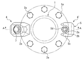
実施例1に係るフランジ離間防止装置につき、図1から図10を参照して説明する。図1及び図2に示されるように、地中に埋設される流体管路は、複数の流体管1,1’,…(管路構成部材)を接続することにより構成されている。尚、流体管1,1’内の流体は、例えば、上水や工業用水、下水等の他、ガスやガスと液体との気液混合体であっても構わない。 The flange separation prevention device according to the first embodiment will be described with reference to FIGS. 1 to 10. As shown in FIGS. 1 and 2, a fluid pipeline buried in the ground is configured by connecting a plurality of fluid pipes 1, 1', ... (Pipeline constituent members). The fluid in the fluid tubes 1, 1'may be, for example, clean water, industrial water, sewage, or the like, or a gas or a gas-liquid mixture of a gas and a liquid.

流体管1,1’は、ダクタイル鋳鉄管であって、断面視略円形状に形成されている。尚、本発明に係る流体管は、その他鋳鉄、鋼等の金属製、あるいはコンクリート製、塩化ビニール製、ポリエチレン製若しくはポリオレフィン製等であってもよい。さらに尚、流体管の内周面はエポキシ樹脂層、モルタル、めっき等により被覆されてもよく、若しくは適宜の材料を粉体塗装により流体管の内周面に被覆してもよい。 The fluid pipes 1 and 1'are ductile cast iron pipes and are formed in a substantially circular shape in cross section. The fluid pipe according to the present invention may be made of other metal such as cast iron or steel, or may be made of concrete, vinyl chloride, polyethylene, polyolefin or the like. Furthermore, the inner peripheral surface of the fluid pipe may be coated with an epoxy resin layer, mortar, plating or the like, or an appropriate material may be coated on the inner peripheral surface of the fluid pipe by powder coating.

ここで、流体管1,1’の接続態様を例に挙げて説明する。流体管1,1’は、端部に管軸に対して直交する方向(径方向)に張り出すフランジ1a,1a’(フランジ接続部)をそれぞれ有しており、フランジ1a,1a’を重ね合わせ、管軸方向に延びる接続ボルト2a及びナット2bによりフランジ1a,1a’を締め付けることで流体管1,1’同士が接続されている。また、一方の流体管1は、短管であるとともに、他方の流体管1’とは反対側の端部に補修弁等の構造部材3が接続されており、構造部材3の外面は流体管1の径方向に大きく張り出すようになっている。尚、構造部材3は、補修弁に限られず、その他バルブや継手などであってもよい。 Here, the connection mode of the fluid pipes 1, 1'will be described as an example. The fluid pipes 1 and 1'have flanges 1a and 1a'(flange connection portions) protruding from the ends in a direction (diametrical direction) orthogonal to the pipe axis, respectively, and the flanges 1a and 1a' are overlapped with each other. In addition, the fluid pipes 1, 1'are connected to each other by tightening the flanges 1a, 1a'by the connecting bolts 2a and the nuts 2b extending in the pipe axis direction. Further, one fluid pipe 1 is a short pipe, and a structural member 3 such as a repair valve is connected to an end opposite to the other fluid pipe 1', and the outer surface of the structural member 3 is a fluid pipe. It is designed to overhang greatly in the radial direction of 1. The structural member 3 is not limited to the repair valve, and may be another valve, a joint, or the like.

このような流体管1,1’の接続態様にあっては、周方向に配置された複数の接続ボルト2a及びナット2bのみで接続しているため、接続強度が不十分であり、流体管1,1’内を流れる流体の圧力や地震などの外力や老朽化による錆などの影響によりフランジ1a,1a’が離間してしまう虞があるため、本実施例においては、フランジ離間防止装置4,4’をフランジ1a,1a’に後付けで取付けることによりフランジ1a,1a’の接続強度を高めている。 In such a connection mode of the fluid pipes 1 and 1', since they are connected only by a plurality of connection bolts 2a and nuts 2b arranged in the circumferential direction, the connection strength is insufficient and the fluid pipe 1'is connected. , 1'Because there is a risk that the flanges 1a and 1a'will be separated due to the pressure of the fluid flowing in 1', the external force such as an earthquake, and the influence of rust due to aging. The connection strength of the flanges 1a and 1a'is increased by attaching the 4'to the flanges 1a and 1a' afterwards.

本実施例にあっては、フランジ離間防止装置4,4’は、フランジ1a,1a’の周方向に所定数等配されており(説明の便宜上、図では径方向に対向した2箇所に管軸方向に反転して取付けた状態で示す)、フランジ離間防止装置4’は、フランジ離間防止装置4に対して上下反転させた状態でフランジ1a,1a’に取付けられている。尚、フランジ1a,1a’に取付けられるフランジ離間防止装置4,4’の数量や取付け向きは、自由に変更しても構わないが、フランジ1a,1a’の周方向に略均等に狭持力を付与するために略等配に複数個取付けられることが好ましい。 In this embodiment, a predetermined number of flange separation prevention devices 4, 4'are arranged in the circumferential direction of the flanges 1a, 1a' (for convenience of explanation, pipes are arranged at two locations facing each other in the radial direction in the drawing. The flange separation prevention device 4'is attached to the flanges 1a, 1a'in a state of being inverted upside down with respect to the flange separation prevention device 4). The quantity and mounting direction of the flange separation prevention devices 4 and 4'attached to the flanges 1a and 1a'may be freely changed, but the holding force is substantially evenly distributed in the circumferential direction of the flanges 1a and 1a'. It is preferable that a plurality of them are attached in a substantially equidistant manner in order to impart the above.

次に、フランジ離間防止装置4の構造について図2〜図6を用いて説明する。図2及び図4に示されるように、フランジ離間防止装置4は、狭持枠5と、狭持体6と、ボルト7と、から主に構成されている。尚、フランジ離間防止装置4,4’は、略同一構成であるため、フランジ離間防止装置4のみ説明し、フランジ離間防止装置4’の説明を省略する。 Next, the structure of the flange separation prevention device 4 will be described with reference to FIGS. 2 to 6. As shown in FIGS. 2 and 4, the flange separation prevention device 4 is mainly composed of a narrow holding frame 5, a narrow holding body 6, and a bolt 7. Since the flange separation prevention devices 4 and 4'have substantially the same configuration, only the flange separation prevention device 4 will be described, and the description of the flange separation prevention device 4'will be omitted.

最初に、狭持枠5について説明する。図2に示されるように、狭持枠5は、一対のフランジ1a,1a’の外周面に対向する基部5aと、基部5aの両端に立設される狭持片部5b,5cと、からなる側面視略コ字形状の部材であり、フランジ1a,1a’の外径側から外嵌可能となっている。 First, the narrow holding frame 5 will be described. As shown in FIG. 2, the narrow holding frame 5 is composed of a base portion 5a facing the outer peripheral surfaces of the pair of flanges 1a, 1a'and narrow holding piece portions 5b, 5c erected at both ends of the base portion 5a. It is a member having a substantially U-shaped side view, and can be fitted from the outer diameter side of the flanges 1a and 1a'.

狭持枠5がフランジ1a,1a’に外嵌された状態にあっては、一方の狭持片部5b(本実施例では下側の狭持片部)は、下側のフランジ1a’の下方に配置され、他方の狭持片部5c(本実施例では上側の狭持片部)は、上側のフランジ1aの上方に配置され、基部5aは、フランジ1a,1a’の外径側に配置される。尚、以下、説明の便宜上、フランジ1a,1a’に取付けられていない状態であっても、狭持枠5における基部5a側をフランジ1a,1a’の外径側、狭持片部5b,5cの自由端部側をフランジ1a,1a’の内径側として説明する。 When the narrow holding frame 5 is fitted onto the flanges 1a and 1a', one narrow holding piece portion 5b (in this embodiment, the lower narrow holding piece portion) is attached to the lower flange 1a'. The other narrowed piece portion 5c (upper narrowed piece portion in this embodiment) is arranged below the upper flange 1a, and the base portion 5a is located on the outer diameter side of the flanges 1a, 1a'. Be placed. In the following, for convenience of explanation, the base portion 5a side of the narrow holding frame 5 is the outer diameter side of the flanges 1a, 1a', and the narrow holding piece portions 5b, 5c even if they are not attached to the flanges 1a, 1a'. The free end side of the above will be described as the inner diameter side of the flanges 1a and 1a'.

図5に示されるように、狭持枠5の具体的な構成について説明すると、基部5aの下部は、狭持枠5の側面視で略垂直に立設する垂直部5dとなっており、基部5aの上部は、上方に向けて垂直部5dに対して外径側に傾斜して延びる傾斜部5eとなっている(特に図5(f)参照)。垂直部5dの下端部には、下側のフランジ1a’の下面に沿って内径側に向けて略水平に延設される一方の狭持片部5bが設けられており(図2参照)、狭持片部5bの延設方向先端部の略中央部には、前記先端部側に開口する切欠部5fが形成されている。これによれば、切欠部5fにナット2bを収容できるため、接続ボルト2a及びナット2bが配設された箇所に狭持片部5bを配置できるようになっている(図1及び図3参照)。 As shown in FIG. 5, a specific configuration of the narrow holding frame 5 will be described. The lower portion of the base portion 5a is a vertical portion 5d that stands substantially vertically in the side view of the narrow holding frame 5, and is a base portion. The upper portion of 5a is an inclined portion 5e extending upward so as to be inclined toward the outer diameter side with respect to the vertical portion 5d (see particularly FIG. 5 (f)). At the lower end of the vertical portion 5d, one narrow holding piece portion 5b extending substantially horizontally toward the inner diameter side along the lower surface of the lower flange 1a'is provided (see FIG. 2). A notch 5f that opens toward the tip is formed at a substantially central portion of the tip of the narrow holding piece 5b in the extending direction. According to this, since the nut 2b can be accommodated in the notch portion 5f, the narrow holding piece portion 5b can be arranged at the place where the connection bolt 2a and the nut 2b are arranged (see FIGS. 1 and 3). ..

また、狭持片部5bの先端部5gは、上方に若干突出しているとともに、突出した上面に複数の溝が網目状に形成されている(特に図5(e)参照)。これによれば、先端部5gに複数の溝により凹凸が形成されることとなるため、フランジ1a’の下面に接触したときの摩擦力が大きくなり、グリップ力を高められている。 Further, the tip portion 5g of the narrow holding piece portion 5b slightly protrudes upward, and a plurality of grooves are formed in a mesh shape on the protruding upper surface (particularly, see FIG. 5E). According to this, since unevenness is formed in the tip portion 5g by a plurality of grooves, the frictional force when contacting the lower surface of the flange 1a'is increased, and the grip force is enhanced.

他方の狭持片部5cは、基部5aの傾斜部5eの上端から内径側上方に傾斜して延設される上壁部5hと、上壁部5hの先端から内径側下方に傾斜して傾斜部5eに略平行に延設される前壁部5jと、傾斜部5e、上壁部5h、前壁部5jで構成される断面視コ字形状の部位の両側面を塞ぐように設けられる一対の側壁部5k,5kと、から構成されている(特に図5(f)参照)。すなわち、傾斜部5e、上壁部5h、前壁部5j、及び側壁部5k,5kにより内径側の斜め下方に向けて開口する収容凹部51(収容部)が形成されており、収容凹部51は、前述した狭持体6を収容可能となっている。 The other narrow holding piece portion 5c has an upper wall portion 5h extending upward from the upper end of the inclined portion 5e of the base portion 5a on the inner diameter side, and an upper wall portion 5h inclined downward on the inner diameter side from the tip of the upper wall portion 5h. A pair provided so as to close both side surfaces of a front wall portion 5j extending substantially parallel to the portion 5e, an inclined portion 5e, an upper wall portion 5h, and a front wall portion 5j having a U-shaped cross section. It is composed of the side wall portions 5k and 5k of the above (particularly see FIG. 5 (f)). That is, the accommodation recess 51 (accommodation portion) that opens diagonally downward on the inner diameter side is formed by the inclined portion 5e, the upper wall portion 5h, the front wall portion 5j, and the side wall portions 5k and 5k, and the accommodation recess 51 is formed. , The above-mentioned narrow holding body 6 can be accommodated.

収容凹部51の内径側は、内径方向に向けて先細りするように構成されるテーパ部5q,5qとなっている(特に図5(c)及び図10(b)参照)。尚、このテーパ部5q,5qは、前壁部5jと側壁部5k,5kとのエッジ部分に形成されているため、側方から見て前壁部5jと同一角度に傾斜している。 The inner diameter side of the accommodating recess 51 is tapered portions 5q and 5q configured to taper in the inner diameter direction (see particularly FIGS. 5 (c) and 10 (b)). Since the tapered portions 5q and 5q are formed at the edge portions of the front wall portion 5j and the side wall portions 5k and 5k, they are inclined at the same angle as the front wall portion 5j when viewed from the side.

上壁部5hには、該上壁部5hの延設方向に対して略直角に貫通するネジ孔5mが形成されており、ネジ孔5mには、ボルト7を螺挿可能となっている。また、上壁部5hの上面側におけるネジ孔5mの周辺には、ボルト7の頭部を一部収容可能な凹部5nが形成されている。 The upper wall portion 5h is formed with a screw hole 5m penetrating substantially at right angles to the extending direction of the upper wall portion 5h, and a bolt 7 can be screwed into the screw hole 5m. Further, a recess 5n capable of partially accommodating the head of the bolt 7 is formed around the screw hole 5 m on the upper surface side of the upper wall portion 5h.

前壁部5jは、ネジ孔5mの中心軸と略平行に内径側下方に傾斜して延設されている。また、前壁部5jの先端縁の略中央部には、下方に開口する切欠部5pが形成されている。この切欠部5pの横幅は、寸法L3となっている(図5(b)参照)。 The front wall portion 5j is inclined downward on the inner diameter side so as to extend substantially parallel to the central axis of the screw hole 5m. Further, a notch 5p that opens downward is formed in a substantially central portion of the tip edge of the front wall portion 5j. The width of the notch 5p is dimension L3 (see FIG. 5B).

次に、狭持体6について図6に基づいて説明する。図6(a)(b)に示されるように、狭持体6は、フランジ1aの上面を押圧する押圧面6aと、ボルト7に押圧される被押圧面6bと、テーパ部5q,5qに接触可能なテーパ部6c,6cと、後述するように接続ボルト2aの頭部に係止可能な係止片6d,6dと、から主に構成されている。 Next, the holding body 6 will be described with reference to FIG. As shown in FIGS. 6A and 6B, the holding body 6 has a pressing surface 6a that presses the upper surface of the flange 1a, a pressed surface 6b that is pressed by the bolt 7, and tapered portions 5q and 5q. It is mainly composed of tapered portions 6c and 6c that can be contacted, and locking pieces 6d and 6d that can be locked to the head of the connecting bolt 2a as described later.

押圧面6aが設けられる狭持体6の下部は、その内径側が押圧面6aよりも上方に位置するように段部が形成されており、該段部の内径側端部から下方に突出するように係止片6d,6dが側方に離間して配設されている。狭持体6における前述した段部が設けられる部位には、接続ボルト2aの頭部を収容可能な切欠収容部6eが形成されており、切欠収容部6eは、その内径側及び下方側が開放されている。 A step portion is formed in the lower portion of the narrow holding body 6 provided with the pressing surface 6a so that the inner diameter side thereof is located above the pressing surface 6a, and the step portion is formed so as to project downward from the inner diameter side end portion of the step portion. Locking pieces 6d and 6d are arranged laterally apart from each other. A notch accommodating portion 6e capable of accommodating the head of the connection bolt 2a is formed in a portion of the narrow holding body 6 where the above-mentioned step portion is provided, and the inner diameter side and the lower side of the notch accommodating portion 6e are opened. ing.

切欠収容部6eの内径側の開口部分は、係止片6d,6dから外径側に離間した位置に形成されており、その開口幅は、通常の規格の接続ボルト2aの頭部の幅よりも僅かに大きい寸法L1となっている。また、切欠収容部6eの上下幅は、接続ボルト2aの頭部の上下の厚みよりも大きく形成されているため、切欠収容部6eに接続ボルト2aの頭部を収容した状態において、接続ボルト2aの頭部と狭持体6とが上下に接触しないようになっている。 The opening on the inner diameter side of the notch accommodating portion 6e is formed at a position separated from the locking pieces 6d and 6d on the outer diameter side, and the opening width is wider than the width of the head of the normal standard connection bolt 2a. Has a slightly larger size L1. Further, since the vertical width of the notch accommodating portion 6e is formed to be larger than the vertical thickness of the head of the connecting bolt 2a, the connecting bolt 2a is in a state where the head of the connecting bolt 2a is accommodated in the notch accommodating portion 6e. The head of the head and the holding body 6 do not come into contact with each other up and down.

また、狭持体6は、テーパ部6c,6cにより上面側から見て内径側が先細りするようになっている。すなわち、狭持体6の内径側端部6hの横幅は、狭持体6の外径側の横幅の寸法L5よりも小さな寸法L4となるように先細りしている(L4<L5)。また、狭持体6における内径側端部6hの横幅の寸法L4は、前述した切欠部5pの横幅の寸法L3よりも小さい(L3>L4)。 Further, the narrow holding body 6 is tapered on the inner diameter side when viewed from the upper surface side due to the tapered portions 6c and 6c. That is, the lateral width of the inner diameter side end portion 6h of the narrow holding body 6 is tapered so as to be a dimension L4 smaller than the lateral width dimension L5 on the outer diameter side of the narrow holding body 6 (L4 <L5). Further, the width dimension L4 of the inner diameter side end portion 6h of the narrow holding body 6 is smaller than the width dimension L3 of the notch portion 5p described above (L3> L4).

尚、狭持体6の内径側端部6hは、上端部が下端部よりも外径側に位置するように傾斜している。さらに、テーパ部6c,6cは、狭持体6における側面と内径側端部6hとのエッジ部分に形成されていることから、側面側から見て上端部が下端部よりも外径側に位置するように傾斜している。 The inner diameter side end portion 6h of the narrow holding body 6 is inclined so that the upper end portion is located on the outer diameter side of the lower end portion. Further, since the tapered portions 6c and 6c are formed at the edge portion between the side surface and the inner diameter side end portion 6h of the holding body 6, the upper end portion is located on the outer diameter side of the lower end portion when viewed from the side surface side. It is tilted to do.

また、狭持体6の両側面には、外径側上方から内径側下方に向けて傾斜する凹形状のスリット6f,6fが形成されており、このスリット6f,6fには、弾性を有する保持部材6g,6gを装着可能となっている。図6(b)に示されるように、、保持部材6g,6gは、狭持体6を狭持枠5の収容凹部51に収容したときに、狭持体6と収容凹部51を構成する側壁部5k,5kとの間で圧縮されるようになっている。これによれば、狭持体6を狭持枠5の収容凹部51に収容したときに、狭持体6と側壁部5k,5kとの間で圧縮された保持部材6g,6gの弾性復元力により、狭持体6が収容凹部51から落下することを防止できる。すなわち、保持部材6g,6gにより狭持枠5と狭持体6をユニット化できるため、フランジ離間防止装置4のフランジ1a,1a’への取付け作業を簡便に行うことができる。 In addition, concave slits 6f, 6f that incline from the upper outer diameter side to the lower inner diameter side are formed on both side surfaces of the narrow holding body 6, and the slits 6f, 6f hold elastic. Members 6g and 6g can be mounted. As shown in FIG. 6B, the holding members 6g and 6g have side walls forming the narrow holding body 6 and the accommodating recess 51 when the narrow holding body 6 is accommodated in the accommodating recess 51 of the narrowing frame 5. It is compressed between the parts 5k and 5k. According to this, when the narrow holding body 6 is housed in the storage recess 51 of the narrow holding frame 5, the elastic restoring force of the holding members 6g and 6g compressed between the narrow holding body 6 and the side wall portions 5k and 5k. Therefore, it is possible to prevent the narrow holding body 6 from falling from the accommodating recess 51. That is, since the narrow holding frame 5 and the narrow holding body 6 can be unitized by the holding members 6g and 6g, the flange separation prevention device 4 can be easily attached to the flanges 1a and 1a'.

また、図6(c)(d)に示されるように、切欠収容部6e’の内径側の開口部分の開口幅を、寸法L1よりも大きい寸法L2とした狭持体6’を用意することで、規格の異なる接続ボルト(接続ボルト2aの頭部よりも大きな頭部を有する接続ボルト)に対応できる。尚、切欠収容部の開口幅を寸法L1よりも小さい寸法とした狭持体を用意して接続ボルト2aの頭部よりも小さな頭部を有する接続ボルトに対応できるようにしてもよい。さらに尚、切欠収容部6eの開口幅が異なる狭持体6を3種類以上用意して規格が異なる種々の接続ボルトに対応できるようにしてもよい。 Further, as shown in FIGS. 6 (c) and 6 (d), a narrow holding body 6'is prepared in which the opening width of the opening portion on the inner diameter side of the notch accommodating portion 6e'is a dimension L2 larger than the dimension L1. Therefore, it is possible to handle connection bolts having different specifications (connection bolts having a head larger than the head of the connection bolt 2a). It should be noted that a narrow holding body having an opening width of the notch accommodating portion smaller than the dimension L1 may be prepared so as to be compatible with a connecting bolt having a head smaller than the head of the connecting bolt 2a. Furthermore, three or more types of narrow holding bodies 6 having different opening widths of the notch accommodating portion 6e may be prepared so as to be compatible with various connecting bolts having different specifications.

次に、フランジ離間防止装置4の動作について図7を用いて説明する。図7(a)に示されるように、ボルト7を締め込む前の状態にあっては、狭持枠5の収容凹部51内に狭持体6がほぼ収まるように収容されるとともに、収容凹部51を構成する上壁部5h、前壁部5jに接触することにより傾動しにくくなっている。尚、収容凹部51と狭持体6との径方向には、若干隙間が形成されているため、該隙間の範囲内で径方向に移動できるようになっている。 Next, the operation of the flange separation prevention device 4 will be described with reference to FIG. As shown in FIG. 7A, in the state before the bolt 7 is tightened, the holding body 6 is accommodated so as to be substantially accommodated in the accommodating recess 51 of the narrowing frame 5, and the accommodating recess is provided. By contacting the upper wall portion 5h and the front wall portion 5j constituting the 51, it becomes difficult to tilt. Since a slight gap is formed in the radial direction between the accommodating recess 51 and the holding body 6, it is possible to move in the radial direction within the range of the gap.

また、ボルト7は、収容凹部51内に狭持体6が収容された状態において、狭持体6の被押圧面6bに対して略垂直となっているとともに、狭持体6の重心の近傍をボルト7の軸線が通るようになっている。また、ボルト7の押圧面7a(先端面)と被押圧面6bとは略平坦面同士で面当接するようになっているが、これに限らず、例えばボルト7の押圧面(先端面)を略球面に形成することで、狭持体6の略平坦面の被押圧面6bと点接触させてもよい。 Further, the bolt 7 is substantially perpendicular to the pressed surface 6b of the narrow holding body 6 in a state where the narrow holding body 6 is housed in the accommodating recess 51, and is near the center of gravity of the narrow holding body 6. The axis of the bolt 7 passes through. Further, the pressing surface 7a (tip surface) of the bolt 7 and the pressed surface 6b are brought into surface contact with each other on substantially flat surfaces, but the present invention is not limited to this, and for example, the pressing surface (tip surface) of the bolt 7 can be pressed. By forming it into a substantially spherical surface, it may be in point contact with the pressed surface 6b of the substantially flat surface of the holding body 6.

図7(b)に示されるように、図7(a)の状態からボルト7を締め込むと、狭持体6がボルト7に押圧され、収容凹部51を形成する内周壁に案内されながら内径側に向けて斜め下方にスライドする。詳しくは、ボルト7の軸線方向に狭持体6の重心が存在することに加え、ボルト7は、狭持体6の被押圧面6bに対して略垂直となっているため、狭持体6がその姿勢を保ったまま、ボルト7の押圧方向と略平行にスライド移動するようになる。すなわち、ボルト7による押圧力を押圧方向とは異なる方向に分散させることなく、狭持体6に対して効率的に伝えることができる。 As shown in FIG. 7 (b), when the bolt 7 is tightened from the state of FIG. 7 (a), the holding body 6 is pressed by the bolt 7 and the inner diameter is guided by the inner peripheral wall forming the accommodating recess 51. Slide diagonally downward toward the side. Specifically, in addition to the center of gravity of the narrow holding body 6 being present in the axial direction of the bolt 7, the bolt 7 is substantially perpendicular to the pressed surface 6b of the narrow holding body 6, so that the narrow holding body 6 Will slide and move substantially parallel to the pressing direction of the bolt 7 while maintaining that posture. That is, the pressing force of the bolt 7 can be efficiently transmitted to the holding body 6 without being dispersed in a direction different from the pressing direction.

また、ボルト7の押圧面7aと被押圧面6bとは面当接するようになっているため、ボルト7により狭持体6を押圧するときに、ボルト7と狭持体6との相対的な傾きが発生しにくく、狭持体6に対してボルト7による押圧力を分散して均等且つ効率的に伝えることができる。また、狭持体6が傾倒しても収容凹部51によりガイドされ、狭持体6の姿勢が維持される。 Further, since the pressing surface 7a of the bolt 7 and the pressed surface 6b are in surface contact with each other, when the holding body 6 is pressed by the bolt 7, the bolt 7 and the holding body 6 are relative to each other. Tilt is unlikely to occur, and the pressing force of the bolt 7 can be dispersed and evenly and efficiently transmitted to the holding body 6. Further, even if the narrow holding body 6 is tilted, it is guided by the accommodating recess 51, and the posture of the narrow holding body 6 is maintained.

狭持体6が所定距離押圧されると、狭持体6の内径側端部6hが狭持枠5における切欠部5pと対応する位置に案内されながら配置される。前述のように、狭持体6における内径側端部6hの横幅の寸法L4は、狭持枠5における切欠部5pの横幅の寸法L3よりも小さいため、狭持体6の内径側端部6hが切欠部5p内に移動(傾動)可能となる。これによれば、狭持体6によりフランジ1a,1a’を押圧するまでは、狭持体6の傾きを調整することができる。 When the narrow holding body 6 is pressed by a predetermined distance, the inner diameter side end portion 6h of the narrow holding body 6 is arranged while being guided to a position corresponding to the notch portion 5p in the narrow holding frame 5. As described above, since the width dimension L4 of the inner diameter side end portion 6h of the narrow holding body 6 is smaller than the width dimension L3 of the notch portion 5p in the narrow holding frame 5, the inner diameter side end portion 6h of the narrow holding body 6 Can move (tilt) in the notch 5p. According to this, the inclination of the narrow holding body 6 can be adjusted until the flanges 1a and 1a'are pressed by the narrow holding body 6.

次に、フランジ離間防止装置4を実際にフランジ1a,1a’に仮設置した状態について図8及び図9に基づいて説明する。尚、ここでは、既存の流体管1,1’にフランジ離間防止装置4を仮設置する場合を例に挙げ説明する。 Next, a state in which the flange separation prevention device 4 is actually temporarily installed on the flanges 1a and 1a'will be described with reference to FIGS. 8 and 9. Here, a case where the flange separation prevention device 4 is temporarily installed in the existing fluid pipes 1 and 1'will be described as an example.

図8は、狭持枠5の収容凹部51内に狭持体6を収容した状態でフランジ1a,1a’の外径側から外嵌させ、狭持体6の押圧面6aと狭持枠5の狭持片部5bとがフランジ1a,1a’の上面及び下面に当接するまでボルト7を締め込んだ仮設置状態を示している。尚、図8の状態にあっては、狭持体6の押圧面6aと狭持枠5の狭持片部5bとがフランジ1aの上面及びフランジ1a’の下面に当接しているが、管軸方向に強く狭持していない状態となっている。 FIG. 8 shows the pressing surface 6a of the narrow holding body 6 and the narrow holding frame 5 by fitting the narrow holding body 6 from the outer diameter side of the flanges 1a and 1a'in a state where the narrow holding body 6 is housed in the accommodating recess 51 of the narrow holding frame 5. It shows a temporary installation state in which the bolt 7 is tightened until the narrow holding piece portion 5b of the above is in contact with the upper surface and the lower surface of the flanges 1a and 1a'. In the state of FIG. 8, the pressing surface 6a of the narrow holding body 6 and the narrow holding piece portion 5b of the narrow holding frame 5 are in contact with the upper surface of the flange 1a and the lower surface of the flange 1a', but the pipe. It is in a state where it is not tightly held in the axial direction.

フランジ離間防止装置4をフランジ1a,1a’に仮設置する場合には、図示しないが、フランジ1a,1a’を接続する既存の接続ボルト及びナットを、本実施例の接続ボルト2a及びナット2bに交換しておく。本実施例の接続ボルト2a及びナット2bは、防錆機能を有し、且つ剛性の高いステンレス等の金属により構成されている。尚、後述するように、接続ボルト2aの頭部が狭持体6の切欠収容部6eに収容されるように、接続ボルト2aの本実施例では六角形状の頭部の回転度合いを調整しておく。 When the flange separation prevention device 4 is temporarily installed on the flanges 1a, 1a', the existing connection bolts and nuts for connecting the flanges 1a, 1a' are attached to the connection bolts 2a and nuts 2b of this embodiment, although not shown. Replace it. The connection bolts 2a and nuts 2b of this embodiment are made of a metal such as stainless steel which has a rust preventive function and has high rigidity. As will be described later, in this embodiment of the connection bolt 2a, the degree of rotation of the hexagonal head is adjusted so that the head of the connection bolt 2a is accommodated in the notch accommodating portion 6e of the holding body 6. back.

フランジ離間防止装置4をフランジ1a,1a’に仮設置した状態にあっては、前述したように、狭持枠5の切欠部5fにナット2bが収容されているとともに、狭持体6の切欠収容部6eに接続ボルト2aの頭部が収容されており、接続ボルト2aの頭部よりも内径側に離間して係止片6d,6dが配置される。 In the state where the flange separation prevention device 4 is temporarily installed on the flanges 1a, 1a', as described above, the nut 2b is housed in the notch 5f of the narrowing frame 5, and the notch of the narrowing body 6 is accommodated. The head of the connecting bolt 2a is housed in the accommodating portion 6e, and the locking pieces 6d and 6d are arranged so as to be separated from the head of the connecting bolt 2a on the inner diameter side.

言い換えれば、狭持枠5と狭持体6との一部が接続ボルト2a及びナット2bと管軸方向に重畳するようになっているため、接続ボルト2a及びナット2bにできるだけ近付けてフランジ離間防止装置4(狭持枠5及び狭持体6)を配置することができ、周方向に隣接する接続ボルト2a及びナット2bの離間幅が小さい場合(例えば、本実施例のようにフランジ1a,1a’に対して接続ボルト2a及びナット2bが8等配されている場合等)であっても、隣接する接続ボルト2a及びナット2bに干渉させることなくフランジ離間防止装置4を配置できる。すなわち、切欠部5f及び切欠収容部6eは、接続ボルト2a及びナット2bと管軸方向に重畳する重畳部として機能している。 In other words, since a part of the narrow holding frame 5 and the narrow holding body 6 overlaps the connecting bolt 2a and the nut 2b in the pipe axis direction, they are brought as close as possible to the connecting bolt 2a and the nut 2b to prevent flange separation. When the device 4 (narrowing frame 5 and narrowing body 6) can be arranged and the separation width between the connecting bolts 2a and the nuts 2b adjacent in the circumferential direction is small (for example, the flanges 1a and 1a as in this embodiment). The flange separation prevention device 4 can be arranged without interfering with the adjacent connection bolts 2a and nuts 2b even when the connection bolts 2a and nuts 2b are arranged in 8 equal parts with respect to'. That is, the notch portion 5f and the notch accommodating portion 6e function as overlapping portions that overlap the connecting bolts 2a and nuts 2b in the pipe axis direction.

また、狭持体6の切欠収容部6eの内面と接続ボルト2aの頭部の外面とが接触しているため、フランジ離間防止装置4が回動することが規制されている。 Further, since the inner surface of the notch accommodating portion 6e of the narrow holding body 6 and the outer surface of the head of the connecting bolt 2a are in contact with each other, the flange separation prevention device 4 is restricted from rotating.

フランジ離間防止装置4をフランジ1a,1a’に仮設置した状態にあっては、狭持体6の押圧面6aと狭持枠5の狭持片部5bとがフランジ1a,1a’を管軸方向に強く狭持していない状態となっているため、外力がかかることにより、フランジ1a,1a’に対して外径側に相対移動することがある。また、フランジ離間防止装置4は、その重心がフランジ1a,1a’よりも外径側に位置しており、且つボルト7が狭持体6を押圧するときに生じる反力が外径側に作用するため、フランジ離間防止装置4をフランジ1a,1a’に仮設置するまでの途中段階では、フランジ離間防止装置4はフランジ1a,1a’に対して外径側に移動し易い。 When the flange separation prevention device 4 is temporarily installed on the flanges 1a, 1a', the pressing surface 6a of the narrow holding body 6 and the narrowing piece portion 5b of the narrowing frame 5 connect the flanges 1a, 1a' to the pipe shaft. Since it is not tightly held in the direction, it may move relative to the outer diameter side with respect to the flanges 1a and 1a'due to the application of an external force. Further, the center of gravity of the flange separation prevention device 4 is located on the outer diameter side of the flanges 1a and 1a', and the reaction force generated when the bolt 7 presses the holding body 6 acts on the outer diameter side. Therefore, in the middle stage until the flange separation prevention device 4 is temporarily installed on the flanges 1a, 1a', the flange separation prevention device 4 tends to move to the outer diameter side with respect to the flanges 1a, 1a'.

図9は、図8の状態から外力により外径側にフランジ離間防止装置4が移動した状態を示している。フランジ離間防止装置4が外径側に移動した場合には、接続ボルト2aの頭部に係止片6d,6dが係止されるとともに、狭持体6のテーパ部6cに狭持枠5のテーパ部5qが係止される(図示略)ことにより、フランジ離間防止装置4がフランジ1a,1a’の外径側に移動して脱落することを防止できる。 FIG. 9 shows a state in which the flange separation prevention device 4 is moved from the state of FIG. 8 to the outer diameter side by an external force. When the flange separation prevention device 4 moves to the outer diameter side, the locking pieces 6d and 6d are locked to the head of the connection bolt 2a, and the narrowing frame 5 is attached to the tapered portion 6c of the narrow holding body 6. By locking the tapered portion 5q (not shown), it is possible to prevent the flange separation prevention device 4 from moving to the outer diameter side of the flanges 1a and 1a'and falling off.

また、狭持体6の切欠収容部6eの内面と接続ボルト2aの頭部の外面とが接触しているとともに、接続ボルト2aの回動中心を挟んだ両側に係止片6d,6dが係止されるため、ボルト7の螺挿に伴うフランジ離間防止装置4の回動を好適に防止できる。また、接続ボルト2aの頭部と係止片6d,6dとの接触により接続ボルト2aが回転することを抑えることができる。 Further, the inner surface of the notch accommodating portion 6e of the narrow holding body 6 and the outer surface of the head of the connecting bolt 2a are in contact with each other, and the locking pieces 6d and 6d are engaged on both sides of the rotation center of the connecting bolt 2a. Since it is stopped, it is possible to suitably prevent the flange separation prevention device 4 from rotating due to the screwing of the bolt 7. Further, it is possible to prevent the connecting bolt 2a from rotating due to the contact between the head of the connecting bolt 2a and the locking pieces 6d and 6d.

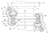
次に、フランジ離間防止装置4を実際にフランジ1a,1a’に設置した状態について、図10に基づいて説明する。図10は、図8の状態からボルト7を締め込んで狭持体6の押圧面6aと狭持枠5の狭持片部5bとによりフランジ1a,1a’を管軸方向に強く狭持した設置状態を示している。 Next, a state in which the flange separation prevention device 4 is actually installed on the flanges 1a and 1a'will be described with reference to FIG. In FIG. 10, the bolt 7 is tightened from the state of FIG. 8, and the flanges 1a and 1a'are strongly narrowed in the pipe axis direction by the pressing surface 6a of the holding body 6 and the narrowing piece portion 5b of the holding frame 5. It shows the installation status.

図10(a)に示されるように、図8の状態からボルト7を締め込むと、狭持体6がフランジ1a,1a’の内径側斜め下方に向けて押圧されるとともに、狭持体6がフランジ1aを押圧する際に発生する反力がボルト7を介して狭持枠5に伝わり、狭持枠5がフランジ1a,1a’の外径側斜め上方に移動する。これにより、狭持体6の押圧面6aと狭持枠5の狭持片部5bとによりフランジ1a,1a’が管軸方向に強く狭持される。 As shown in FIG. 10A, when the bolt 7 is tightened from the state of FIG. 8, the holding body 6 is pressed diagonally downward on the inner diameter side of the flanges 1a, 1a', and the holding body 6 is pressed. The reaction force generated when the flange 1a is pressed is transmitted to the narrow holding frame 5 via the bolt 7, and the narrow holding frame 5 moves diagonally upward on the outer diameter side of the flanges 1a, 1a'. As a result, the flanges 1a and 1a'are strongly held in the pipe axis direction by the pressing surface 6a of the holding body 6 and the holding piece portion 5b of the holding frame 5.

また、狭持片部5bの先端部5gがフランジ1a’の下面に直接的に接触するようになっており、該先端部5gには、複数の凹凸が形成されていることから、フランジ1a’の下面に接触したときの摩擦力が大きく作用し、狭持片部5bとフランジ1a’の下面とが摺動することを抑制できる。 Further, the tip portion 5g of the narrow holding piece portion 5b comes into direct contact with the lower surface of the flange 1a', and since the tip portion 5g is formed with a plurality of irregularities, the flange 1a'. A large frictional force acts when it comes into contact with the lower surface of the flange, and it is possible to prevent the narrow holding piece portion 5b and the lower surface of the flange 1a'from sliding.

図10(b)に示されるように、図8の状態からボルト7を締め込むと、狭持体6がフランジ1a,1a’の内径側斜め下方に移動し、狭持枠5がフランジ1a,1a’の外径側斜め上方に移動することから、狭持枠5のテーパ部5q,5q(移動規制部)に狭持体6のテーパ部6c,6cが接触し、狭持体6の内径側斜め下方への移動が規制される。尚、本実施例にあっては、狭持枠5のテーパ部5q,5qと狭持体6のテーパ部6c,6cとが接触するため、狭持枠5の前壁部5jと狭持体6の内径側端部6hとは接触しない。 As shown in FIG. 10B, when the bolt 7 is tightened from the state of FIG. 8, the holding body 6 moves diagonally downward on the inner diameter side of the flanges 1a, 1a', and the holding frame 5 moves diagonally downward on the inner diameter side of the flanges 1a, 1a. Since it moves diagonally upward on the outer diameter side of 1a', the tapered portions 6c and 6c of the narrow holding body 6 come into contact with the tapered portions 5q and 5q (movement restricting portion) of the narrow holding frame 5, and the inner diameter of the narrow holding body 6 is increased. Movement diagonally downward is restricted. In this embodiment, since the tapered portions 5q and 5q of the narrow holding frame 5 and the tapered portions 6c and 6c of the narrow holding body 6 come into contact with each other, the front wall portion 5j of the narrow holding frame 5 and the narrow holding body 5j come into contact with each other. It does not come into contact with the inner diameter side end portion 6h of 6.

さらに、テーパ部5q,5qとテーパ部6c,6cとは、外径側上方から内径側下方に傾斜していることから、狭持体6の内径側斜め下方への移動が管軸方向下方側(フランジ1a側)への移動に変換される。このように、ボルト7とテーパ部5q,5qとにより狭持体6をフランジ1aに対して強力に押圧することができる。 Further, since the tapered portions 5q and 5q and the tapered portions 6c and 6c are inclined from the upper outer diameter side to the lower inner diameter side, the movement of the narrow holding body 6 diagonally downward on the inner diameter side is on the lower side in the pipe axis direction. It is converted to the movement to (flange 1a side). In this way, the narrow holding body 6 can be strongly pressed against the flange 1a by the bolt 7 and the tapered portions 5q and 5q.

また、前述したように、切欠収容部6eに接続ボルト2aの頭部を収容した状態において、接続ボルト2aの頭部と狭持体6とが上下に接触しないようになっているため、狭持体6の押圧面6aによりフランジ1aに安定した状態で押圧できる。なお上述したように、ボルト7の締め込みにより、フランジ1a,1a’が強く挟圧された結果、フランジ1a,1a’に介在した図示しないパッキンが潰れ、フランジ1a,1a’同士の離間距離が狭まった場合、接続ボルト2a及びナット2bを増し締めすると良い。増し締めの際には、接続ボルト2aの頭部は狭持体6の切欠収容部6eに収容され回動が規制されているため、挟持枠5の切欠部5fに遊嵌状態で収容されたナット2bを図示しない工具等で回動操作することができる。 Further, as described above, when the head of the connecting bolt 2a is accommodated in the notch accommodating portion 6e, the head of the connecting bolt 2a and the holding body 6 do not come into contact with each other in the vertical direction. The pressing surface 6a of the body 6 can press the flange 1a in a stable state. As described above, as a result of the flanges 1a and 1a'being strongly pinched by tightening the bolt 7, the packing (not shown) interposed between the flanges 1a and 1a' is crushed, and the separation distance between the flanges 1a and 1a' is increased. If it becomes narrow, it is advisable to retighten the connection bolt 2a and the nut 2b. At the time of retightening, the head of the connecting bolt 2a is accommodated in the notch accommodating portion 6e of the holding body 6 and its rotation is restricted, so that the head of the connecting bolt 2a is accommodated in the notch portion 5f of the holding frame 5 in a loosely fitted state. The nut 2b can be rotated by a tool or the like (not shown).

以上説明したように、ボルト7は、狭持体6と狭持片部5bとで一対のフランジ1a,1a’を管軸方向に狭持した状態において、流体管1,1’の管軸方向に対して外径側に傾斜して狭持枠5に取付けられており、流体管1,1’の管軸方向に対し斜めに進退するようになっている。 As described above, the bolt 7 has a pair of flanges 1a and 1a'held by the narrowing body 6 and the narrowing piece portion 5b in the pipe axial direction, and the fluid pipes 1 and 1'are held in the pipe axial direction. It is attached to the narrow holding frame 5 so as to be inclined toward the outer diameter side, and is adapted to advance and retreat diagonally with respect to the pipe axis direction of the fluid pipes 1, 1'.

これによれば、本実施例のように、流体管1,1’の管軸方向に流体管1の径方向に大きく張り出す補修弁等の構造部材3が取付けられている場合であっても、ボルト7を流体管1,1’の管軸方向に対して斜めに進退させることで、構造部材3との干渉を避けてボルト7の締め付け作業を行うことができる。 According to this, even when a structural member 3 such as a repair valve that greatly projects in the radial direction of the fluid pipe 1 is attached in the pipe axial direction of the fluid pipes 1, 1'as in the present embodiment. By moving the bolt 7 diagonally forward and backward with respect to the pipe axis direction of the fluid pipes 1, 1', the bolt 7 can be tightened while avoiding interference with the structural member 3.

さらに、ボルト7が流体管1,1’の径方向に大きく張り出すことを抑制できるため、ボルト7の締め付け作業にかかる作業スペースを小さくすることできる。また、該作業後の埋め戻し時にかかる負荷(土圧等)への耐久性を高めることができるとともに、フランジ1a,1a’の周辺で所定の工事を行う際の再掘削時等に重機などが干渉し難いため、フランジ離間防止装置4の破損を回避して効率的にフランジ1a,1a’を挟持できる。 Further, since it is possible to prevent the bolt 7 from protruding significantly in the radial direction of the fluid pipes 1, 1', the work space required for the tightening work of the bolt 7 can be reduced. In addition, the durability against the load (earth pressure, etc.) applied during backfilling after the work can be improved, and heavy machinery or the like can be used during re-excavation when performing predetermined work around the flanges 1a, 1a'. Since it is difficult to interfere with each other, it is possible to avoid damage to the flange separation prevention device 4 and efficiently sandwich the flanges 1a and 1a'.

また、本実施例では、狭持体6と狭持片部5bとで一対のフランジ1a,1a’を管軸方向に狭持した状態において、ボルト7は、流体管1,1’の管軸方向に対して略30度外径側に傾斜している。これによれば、ボルト7の押圧方向を流体管1,1’の管軸方向(フランジ1a,1a’の狭持方向)に近付けることができるため、ボルト7の押圧力をフランジ1a,1a’の狭持方向とは異なる方向に分散させることなく、フランジ1a,1a’の狭持方向に効率よく狭持体6に伝えることができる。 Further, in this embodiment, in a state where the narrow holding body 6 and the narrow holding piece portion 5b hold the pair of flanges 1a and 1a'in the pipe axis direction, the bolt 7 is the pipe shaft of the fluid pipes 1, 1'. It is inclined to the outer diameter side by about 30 degrees with respect to the direction. According to this, the pressing direction of the bolt 7 can be brought closer to the pipe axial direction of the fluid tubes 1, 1'(the holding direction of the flanges 1a, 1a'), so that the pressing force of the bolt 7 is applied to the flanges 1a, 1a'. Can be efficiently transmitted to the holding body 6 in the holding direction of the flanges 1a, 1a'without being dispersed in a direction different from the holding direction of.

尚、本実施例では、ボルト7が流体管1,1’の管軸方向に対して略30度外径側に傾斜する形態を例示したが、これに限られず、流体管1,1’の管軸方向に対するボルト7の角度は自由に変更できるが、ボルト7の押圧力をフランジ1a,1a’の狭持方向に効率よく伝えるという観点から、ボルト7は、流体管1,1’の管軸方向に対して45度以下の範囲で傾斜していることが好ましい。また、本実施例では、ボルト7の軸線が流体管1,1’の管軸と交差する形態を例示したが、ボルト7の軸線が流体管1,1’の管軸と交差しないようになっていてもよい。 In this embodiment, the bolt 7 is inclined to the outer diameter side by about 30 degrees with respect to the pipe axis direction of the fluid pipes 1, 1', but the present invention is not limited to this, and the fluid pipes 1, 1' The angle of the bolt 7 with respect to the pipe axis direction can be freely changed, but from the viewpoint of efficiently transmitting the pressing force of the bolt 7 in the holding direction of the flanges 1a, 1a', the bolt 7 is a pipe of the fluid pipes 1, 1'. It is preferable that it is inclined in a range of 45 degrees or less with respect to the axial direction. Further, in this embodiment, the embodiment in which the axis of the bolt 7 intersects with the pipe axis of the fluid pipes 1, 1'is illustrated, but the axis of the bolt 7 does not intersect with the pipe axis of the fluid pipes 1, 1'. You may be.

また、フランジ離間防止装置4,4’のように上下反転させた状態でフランジ1a,1a’に取付けることができる。具体的には、フランジ離間防止装置4の場合、ボルト7が流体管1,1’の管軸方向に対して略30度外径側に傾斜することとなり、フランジ離間防止装置4’の場合、ボルト7が流体管1,1’の管軸方向に対して略150度外径側に傾斜する。よって、フランジ離間防止装置を取付ける向きによって、流体管1,1’の管軸方向に対するボルト7の傾斜角度が変更されるため、種々の構造部材3に合わせてフランジ離間防止装置4,4’をフランジ1a,1a’に取付けることが可能となる。 Further, it can be attached to the flanges 1a, 1a'in a state of being turned upside down like the flange separation prevention devices 4, 4'. Specifically, in the case of the flange separation prevention device 4, the bolt 7 is inclined to the outer diameter side of the fluid pipes 1, 1'by approximately 30 degrees with respect to the pipe axis direction, and in the case of the flange separation prevention device 4', the bolt 7 is inclined to the outer diameter side. The bolt 7 inclines toward the outer diameter side of the fluid pipes 1, 1'by approximately 150 degrees with respect to the pipe axis direction. Therefore, the inclination angle of the bolt 7 with respect to the pipe axis direction of the fluid pipes 1 and 1'is changed depending on the direction in which the flange separation prevention device is attached. It can be attached to the flanges 1a and 1a'.

また、ボルト7を締め付けてフランジ1a,1a’を狭持した際には、フランジ離間防止装置4をボルト7の軸回りに回動するような力が発生するが、前述のように、狭持体6の切欠収容部6eと接続ボルト2aの頭部とが接触しているため、フランジ離間防止装置4が回動することが規制される。 Further, when the bolt 7 is tightened to narrow the flanges 1a and 1a', a force is generated that causes the flange separation prevention device 4 to rotate around the axis of the bolt 7, but as described above, the holding is narrowed. Since the notch accommodating portion 6e of the body 6 and the head of the connecting bolt 2a are in contact with each other, the rotation of the flange separation prevention device 4 is restricted.

また、図3に示されるように、フランジ離間防止装置4をフランジ1a,1a’に取付けた状態において、狭持枠5の基部5aの内径側の側縁部5r,5rがフランジ1a,1a’の外径側近傍に配置されることから、ボルト7の締め付け操作によりフランジ離間防止装置4が若干回動したとしても、側縁部5r,5rがフランジ1a,1a’に当接するため、フランジ離間防止装置4の回動が確実に規制される。 Further, as shown in FIG. 3, in a state where the flange separation prevention device 4 is attached to the flanges 1a, 1a', the side edge portions 5r, 5r on the inner diameter side of the base portion 5a of the narrow holding frame 5 are the flanges 1a, 1a'. Since it is arranged near the outer diameter side of the above, even if the flange separation prevention device 4 is slightly rotated by the tightening operation of the bolt 7, the side edge portions 5r and 5r come into contact with the flanges 1a and 1a', so that the flange separation is performed. The rotation of the prevention device 4 is reliably regulated.

尚、フランジ離間防止装置4を構成する狭持枠5、狭持体6、及びボルト7は、樹脂や絶縁塗装、めっき、ゴムライニングなどの保護層により被覆されていてもよい。これによれば、狭持枠5、狭持体6、及びボルト7に錆などが発生することを抑制できる。 The narrow holding frame 5, the narrow holding body 6, and the bolt 7 constituting the flange separation prevention device 4 may be covered with a protective layer such as resin, insulating coating, plating, or rubber lining. According to this, it is possible to suppress the occurrence of rust or the like on the narrow holding frame 5, the narrow holding body 6, and the bolt 7.

次に、図11〜図13を用いて変形例1〜変形例4を説明する。図11(a)に示されるように、変形例1のフランジ離間防止装置41は、狭持枠511の前壁部51jに切欠部5pが形成されていない。これによれば、狭持体6は、ボルト7により所定距離押圧されても前壁部51jに干渉して傾動することが規制される。よって、変形例1にあっては、狭持体6が姿勢を保った状態(傾動が規制された状態)でフランジ1a,1a’に向けて移動するようになるため、狭持体6を基準としてフランジ1a,1a’に対するフランジ離間防止装置41の位置合わせを行いやすい。 Next, Modifications 1 to 4 will be described with reference to FIGS. 11 to 13. As shown in FIG. 11A, in the flange separation prevention device 41 of the modified example 1, the notch portion 5p is not formed in the front wall portion 51j of the narrow holding frame 511. According to this, even if the holding body 6 is pressed by the bolt 7 for a predetermined distance, it is restricted from interfering with the front wall portion 51j and tilting. Therefore, in the modified example 1, the narrow holding body 6 moves toward the flanges 1a and 1a'while maintaining the posture (in a state where the tilt is restricted), so that the narrow holding body 6 is used as a reference. As a result, it is easy to align the flange separation prevention device 41 with respect to the flanges 1a and 1a'.

また、フランジ離間防止装置41は、前記実施例のテーパ部5q,5qを設けずに、前壁部51jが狭持体6の移動規制部として機能している。これによれば、ボルト7と略平行に傾斜する前壁部51jと狭持体6の内径側端部6hとが面当接することとなるため、狭持枠511と狭持体6との適切な相対的な角度を保つようにガイドされ、一対のフランジ1a,1a’を好適に狭持することができる。 Further, in the flange separation prevention device 41, the front wall portion 51j functions as a movement restricting portion of the narrow holding body 6 without providing the tapered portions 5q and 5q of the above embodiment. According to this, since the front wall portion 51j inclined substantially parallel to the bolt 7 and the inner diameter side end portion 6h of the narrow holding body 6 come into surface contact with each other, the narrow holding frame 511 and the narrow holding body 6 are suitable. Guided to maintain a relative relative angle, the pair of flanges 1a, 1a'can be suitably narrowed.

図11(b)に示されるように、変形例2のフランジ離間防止装置42は、前記実施例のテーパ部5q,5qが設けられておらず、前壁部52jの外径側の先端縁52aが移動規制部として機能して狭持体6の内径側端部6hに接触するようになっている。このように、移動規制部は、狭持体6と面当接するものに限られず、狭持体6に対して線接触するものでもよい。また、特に図示しないが、移動規制部は、狭持体6に対して点接触するようなものであってもよい。すなわち、移動規制部は、フランジ1a,1a’を狭持した状態において、狭持体6の内径方向への移動を規制できるものであればよい。 As shown in FIG. 11B, the flange separation prevention device 42 of the modified example 2 is not provided with the tapered portions 5q and 5q of the embodiment, and the tip edge 52a on the outer diameter side of the front wall portion 52j is not provided. Functions as a movement restricting portion and comes into contact with the inner diameter side end portion 6h of the holding body 6. As described above, the movement restricting portion is not limited to the one that comes into surface contact with the narrow holding body 6, and may be the one that makes line contact with the narrow holding body 6. Further, although not particularly shown, the movement restricting unit may be in point contact with the holding body 6. That is, the movement restricting unit may be capable of restricting the movement of the narrow holding body 6 in the inner diameter direction while holding the flanges 1a and 1a'.

尚、狭持体6の内径側端部6hは、ボルト7と略平行に傾斜するものに限られず、移動規制部に接触可能であればよく、例えば、ボルト7と交差するように形成されていてもよい。 The inner diameter side end portion 6h of the narrow holding body 6 is not limited to one that is inclined substantially parallel to the bolt 7, and may be in contact with the movement restricting portion, and is formed so as to intersect the bolt 7, for example. You may.

また、図12に示されるように、変形例3のフランジ離間防止装置43は、狭持体63の切欠収容部63eが下面から見て径方向に長い略楕円形状を成すように全周に亘り壁部63a(係止片)に囲われて構成されている。これによれば、フランジ離間防止装置43が径方向に移動しても、切欠収容部63eに収容される接続ボルト2aに壁部63aが接触するため、フランジ離間防止装置43の径方向の移動を規制できる。 Further, as shown in FIG. 12, the flange separation prevention device 43 of the modified example 3 covers the entire circumference so that the notch accommodating portion 63e of the narrow holding body 63 forms a substantially elliptical shape that is long in the radial direction when viewed from the lower surface. It is configured to be surrounded by a wall portion 63a (locking piece). According to this, even if the flange separation prevention device 43 moves in the radial direction, the wall portion 63a comes into contact with the connection bolt 2a accommodated in the notch accommodating portion 63e, so that the flange separation prevention device 43 can move in the radial direction. Can be regulated.

尚、係止片は、狭持体に設けられる形態を例示したが、これに限られず、例えば、狭持枠5の前壁部5jなどに接続ボルト2aに係止可能な係止片を設け、フランジ離間防止装置の径方向の移動を規制してもよい。 The locking piece is illustrated in a form provided on the holding body, but the present invention is not limited to this, and for example, a locking piece that can be locked to the connection bolt 2a is provided on the front wall portion 5j of the holding frame 5 or the like. , The radial movement of the flange separation prevention device may be restricted.

図13に示すように、変形例4のフランジ離間防止装置44は、狭持体64に接続ボルト2aの頭部を収容可能な切欠収容部が設けられていない。これによれば、狭持体64の下面全体を押圧面64aとすることができるため、フランジ1a,1a’にフランジ離間防止装置43を取付ける際に、広い押圧面64aを使ってフランジ1aを押圧できるため、フランジ1a,1a’を安定して押圧することができる。 As shown in FIG. 13, the flange separation prevention device 44 of the modified example 4 is not provided with a notch accommodating portion capable of accommodating the head of the connecting bolt 2a in the holding body 64. According to this, since the entire lower surface of the narrow holding body 64 can be a pressing surface 64a, when the flange separation prevention device 43 is attached to the flanges 1a, 1a', the flange 1a is pressed using the wide pressing surface 64a. Therefore, the flanges 1a and 1a'can be pressed stably.

例えば、図13(b)に示されるように、フランジ1a,1a’の周方向に接続ボルト2a及びナット2bが4等配され、隣接する接続ボルト2a及びナット2bの間の領域が比較的大きい場合などに有用である。 For example, as shown in FIG. 13B, the connecting bolts 2a and nuts 2b are arranged in four equal parts in the circumferential direction of the flanges 1a and 1a', and the area between the adjacent connecting bolts 2a and nuts 2b is relatively large. It is useful in cases such as.

以上、本発明の実施例を図面により説明してきたが、具体的な構成はこれら実施例に限られるものではなく、本発明の要旨を逸脱しない範囲における変更や追加があっても本発明に含まれる。 Although examples of the present invention have been described above with reference to the drawings, the specific configuration is not limited to these examples, and any changes or additions within the scope of the gist of the present invention are included in the present invention. Is done.

前記実施例及び変形例1〜4では、流体管1,1’を管路構成部材として説明したが、これに限られず、管路を構成する補修弁や消火栓等のバルブ、筐体なども管路構成部材に含まれる。 In the above-described Examples and Modifications 1 to 4, the fluid pipes 1 and 1'have been described as pipeline constituent members, but the present invention is not limited to this, and repair valves, fire hydrants and other valves, housings and the like that constitute the pipeline are also pipes. Included in road components.

1,1’ 流体管(管路構成部材)
1a,1a’ フランジ
2a 接続ボルト
2b ナット
3 構造部材
4,4’ フランジ離間防止装置
5 狭持枠
5b,5c 狭持片部
5f 切欠部(重畳部)
5q テーパ部(移動規制部)
5r 側縁部(移動規制部)
6,6’ 狭持体
6b 被押圧面
6d 係止片
6e,6e’ 切欠収容部(重畳部)
6g 保持部材
6h 内径側端部(傾斜面)
7 ボルト
41,42,43,44 フランジ離間防止装置
51 収容凹部(収容部)
51j 前壁部(移動規制部、傾斜面)
52a 先端縁(移動規制部)
63 狭持体
63a 壁部(係止片)
63e 切欠収容部(収容部)
64 狭持体
511 狭持枠
1,1'fluid pipe (pipeline component)
1a, 1a'Flange 2a Connection bolt 2b Nut 3 Structural member 4, 4'Flange separation prevention device 5 Narrowing frame 5b, 5c Narrowing piece 5f Notch (superimposing part)
5q taper part (movement regulation part)
5r side edge (movement regulation part)
6,6'Narrowing body 6b Pressed surface 6d Locking pieces 6e, 6e' Notch accommodating part (superimposing part)
6g Holding member 6h Inner diameter side end (inclined surface)
7 Bolts 41, 42, 43, 44 Flange separation prevention device 51 Accommodation recess (accommodation part)
51j Front wall part (movement regulation part, inclined surface)
52a Tip edge (movement control part)
63 Narrow body 63a Wall (locking piece)
63e Notch accommodation (accommodation)
64 Narrow body 511 Narrow frame

Claims (8)

一対の管路構成部材を接続する一対のフランジにおける一方のフランジの管軸方向外側に配置される狭持片部を有する狭持枠と、他方のフランジの管軸方向外側に配置される狭持体と、前記狭持体に押圧力を付与するボルトと、を備え、前記ボルトにより前記狭持体を押圧することにより、該狭持体と前記狭持片部とで前記一対のフランジを狭持するフランジ離間防止装置であって、
前記ボルトは、前記狭持体と前記狭持片部とで前記一対のフランジを狭持した状態において、前記管路構成部材の管軸方向に対して斜めに進退するように前記狭持枠に取付けられており、前記狭持体は、前記ボルトに押圧される被押圧面を有し、前記ボルトは、前記被押圧面に対し略垂直に押圧することを特徴とするフランジ離間防止装置。
A narrow holding frame having a narrow holding piece portion arranged outside the pipe axis direction of one flange in a pair of flanges connecting a pair of pipeline constituent members, and a narrow holding frame arranged outside the pipe axis direction of the other flange. A body and a bolt that applies a pressing force to the narrow holding body are provided, and by pressing the narrow holding body with the bolt, the pair of flanges are narrowed between the narrow holding body and the narrow holding piece portion. It is a flange separation prevention device to hold
The bolt is attached to the holding frame so as to advance and retreat diagonally with respect to the pipe axis direction of the pipeline constituent member in a state where the pair of flanges are held by the holding body and the holding piece portion. A flange separation prevention device that is attached and has a pressed surface that is pressed against the bolt, and the bolt presses substantially perpendicular to the pressed surface.
前記ボルトは、前記狭持体の移動方向と略平行に延びていることを特徴とする請求項1に記載のフランジ離間防止装置。 The flange separation prevention device according to claim 1, wherein the bolt extends substantially parallel to the moving direction of the holding body. 前記狭持枠は、前記狭持体を収容可能な収容部を有し、
前記収容部の前記管路構成部材の内径側には、前記狭持体に当接する移動規制部が設けられていることを特徴とする請求項1または2に記載のフランジ離間防止装置。
The narrowing frame has an accommodating portion capable of accommodating the narrowing body, and has an accommodating portion.
The flange separation prevention device according to claim 1 or 2 , wherein a movement restricting portion that comes into contact with the narrow holding body is provided on the inner diameter side of the conduit constituent member of the accommodating portion.
前記移動規制部と前記狭持体とは、前記ボルトと略平行に延びる傾斜面をそれぞれ有し、前記傾斜面同士が面当接することを特徴とする請求項に記載のフランジ離間防止装置。 The flange separation prevention device according to claim 3 , wherein the movement restricting portion and the narrow holding body each have an inclined surface extending substantially parallel to the bolt, and the inclined surfaces come into surface contact with each other. 前記狭持体には、前記一対のフランジを接続する接続ボルトの前記管路構成部材の内径側に係止可能な係止片を有していることを特徴とする請求項1ないしのいずれかに記載のフランジ離間防止装置。 Wherein the holding portions are all of claims 1 to 4, characterized in that it has a lockable locking piece on the inner diameter side of the conduit component of the connecting bolt for connecting the pair of flanges Flange separation prevention device described in Crab. 前記ボルトは、前記管路構成部材の管軸に対して45度以下の範囲で傾斜していることを特徴とする請求項1ないしのいずれかに記載のフランジ離間防止装置。 The flange separation prevention device according to any one of claims 1 to 5 , wherein the bolt is inclined in a range of 45 degrees or less with respect to the pipe axis of the pipeline constituent member. 前記狭持体は、少なくとも一部に前記一対のフランジを接続する接続ボルトと管軸方向に重畳する重畳部を備えることを特徴とする請求項1ないしのいずれかに記載のフランジ離間防止装置。 The flange separation prevention device according to any one of claims 1 to 6 , wherein the narrowed body includes at least a part of a connecting bolt connecting the pair of flanges and a superimposing portion overlapping in the pipe axis direction. .. 前記狭持体を前記狭持枠に保持する保持部材が前記狭持体に設けられていることを特徴とする請求項1ないしのいずれかに記載のフランジ離間防止装置。 The flange separation prevention device according to any one of claims 1 to 7 , wherein a holding member for holding the narrow holding body in the narrow holding frame is provided in the narrow holding body.
JP2017248956A 2017-12-26 2017-12-26 Flange separation prevention device Active JP6962811B2 (en)

Priority Applications (2)

Application Number Priority Date Filing Date Title
JP2017248956A JP6962811B2 (en) 2017-12-26 2017-12-26 Flange separation prevention device
JP2021166615A JP7161018B2 (en) 2017-12-26 2021-10-11 How to install the flange separation prevention device

Applications Claiming Priority (1)

Application Number Priority Date Filing Date Title
JP2017248956A JP6962811B2 (en) 2017-12-26 2017-12-26 Flange separation prevention device

Related Child Applications (1)

Application Number Title Priority Date Filing Date
JP2021166615A Division JP7161018B2 (en) 2017-12-26 2021-10-11 How to install the flange separation prevention device

Publications (2)

Publication Number Publication Date
JP2019113155A JP2019113155A (en) 2019-07-11
JP6962811B2 true JP6962811B2 (en) 2021-11-05

Family

ID=67223647

Family Applications (1)

Application Number Title Priority Date Filing Date
JP2017248956A Active JP6962811B2 (en) 2017-12-26 2017-12-26 Flange separation prevention device

Country Status (1)

Country Link
JP (1) JP6962811B2 (en)

Families Citing this family (1)

* Cited by examiner, † Cited by third party
Publication number Priority date Publication date Assignee Title
JP7330061B2 (en) * 2019-10-21 2023-08-21 コスモ工機株式会社 Flange stiffener

Family Cites Families (13)

* Cited by examiner, † Cited by third party
Publication number Priority date Publication date Assignee Title
JPS60544Y2 (en) * 1977-02-22 1985-01-09 矢野技研株式会社 Pipe deviation prevention device at water pipe joints
CA2094569C (en) * 1992-05-08 1998-07-14 Dennis H. Vaders Press die clamp
US5505503A (en) * 1992-07-31 1996-04-09 Boivin; Sylvain Conduit system
DE29615393U1 (en) * 1995-11-25 1996-10-31 Gutehoffnungshuette Man Non-positive and positive connection of rotationally symmetrical components
JP4412589B2 (en) * 2004-02-17 2010-02-10 コスモ工機株式会社 Flange joining device
JP6086580B2 (en) * 2012-09-21 2017-03-01 協和工業株式会社 Combined structure of water supply equipment
JP6262544B2 (en) * 2014-01-21 2018-01-17 株式会社水道技術開発機構 Flange joint reinforcing structure and annular protective member used therefor
JP6327897B2 (en) * 2014-03-19 2018-05-23 コスモ工機株式会社 Flange separation prevention device
JP6591738B2 (en) * 2014-09-05 2019-10-16 コスモ工機株式会社 Flange separation prevention device
JP6498938B2 (en) * 2015-01-05 2019-04-10 岡山市 Joining reinforcement jig
JP6680559B2 (en) * 2016-02-17 2020-04-15 岡山市 Reinforcement jig for joint and mounting method of reinforcement jig
CN205479848U (en) * 2016-04-05 2016-08-17 江苏长新电工机械集团有限公司 Novel hubbed flange
JP6063085B1 (en) * 2016-08-05 2017-01-18 マイクロ波化学株式会社 Waveguide connection device and waveguide connection clamp

Also Published As

Publication number Publication date
JP2019113155A (en) 2019-07-11

Similar Documents

Publication Publication Date Title
US7980598B2 (en) Pipe joint locking device
US7748100B2 (en) Methods of securing a pipe
US8807601B2 (en) Compression seal assembly
US20060244260A1 (en) Joint restraint assembly
CN102797910B (en) Self-locking looseness-proof pipe clamp
US10760602B2 (en) Systems and methods for connecting a structural member to a pile
JP6962811B2 (en) Flange separation prevention device
US8656942B2 (en) Length-adjustable pressure-retaining piping components
JP2022008994A (en) Attachment method of flange separation prevention device
US11318592B2 (en) Hydraulic torque wrench
JP6935888B2 (en) How to install the reinforcement jig
JP6591738B2 (en) Flange separation prevention device
JP7330061B2 (en) Flange stiffener
JP2015178850A (en) Flange separation prevention device
JP3217571U (en) Housing type pipe fitting
JP6797479B2 (en) Leakage prevention device
JPWO2019187398A1 (en) Locking device for pipe fittings and valve fittings
JP6908239B2 (en) Joint reinforcement jig
US4082323A (en) Box hole drill steel
TWI792655B (en) Torque absorbing surface
JP2023028137A (en) Detachment prevention device
JP6995311B2 (en) Joint reinforcement jig
JP2022061481A (en) Flange reinforcing tool
JP2022011100A (en) Flange reinforcement tool
JP4861285B2 (en) Piping repair tool

Legal Events

Date Code Title Description
A621 Written request for application examination

Free format text: JAPANESE INTERMEDIATE CODE: A621

Effective date: 20200924

A977 Report on retrieval

Free format text: JAPANESE INTERMEDIATE CODE: A971007

Effective date: 20210616

A131 Notification of reasons for refusal

Free format text: JAPANESE INTERMEDIATE CODE: A131

Effective date: 20210622

A521 Written amendment

Free format text: JAPANESE INTERMEDIATE CODE: A523

Effective date: 20210818

TRDD Decision of grant or rejection written
A01 Written decision to grant a patent or to grant a registration (utility model)

Free format text: JAPANESE INTERMEDIATE CODE: A01

Effective date: 20210921

A61 First payment of annual fees (during grant procedure)

Free format text: JAPANESE INTERMEDIATE CODE: A61

Effective date: 20211014

R150 Certificate of patent or registration of utility model

Ref document number: 6962811

Country of ref document: JP

Free format text: JAPANESE INTERMEDIATE CODE: R150