JP6959269B2 - Process for High Severity Flow Contact Cracking Systems - Google Patents
Process for High Severity Flow Contact Cracking Systems Download PDFInfo
- Publication number
- JP6959269B2 JP6959269B2 JP2018566445A JP2018566445A JP6959269B2 JP 6959269 B2 JP6959269 B2 JP 6959269B2 JP 2018566445 A JP2018566445 A JP 2018566445A JP 2018566445 A JP2018566445 A JP 2018566445A JP 6959269 B2 JP6959269 B2 JP 6959269B2
- Authority
- JP
- Japan
- Prior art keywords
- catalyst
- weight
- gas condensate
- zeolite
- zsm
- Prior art date
- Legal status (The legal status is an assumption and is not a legal conclusion. Google has not performed a legal analysis and makes no representation as to the accuracy of the status listed.)
- Active
Links
- 238000000034 method Methods 0.000 title claims description 61
- 238000005336 cracking Methods 0.000 title claims description 5
- 239000003054 catalyst Substances 0.000 claims description 104
- 239000010457 zeolite Substances 0.000 claims description 63
- 229910021536 Zeolite Inorganic materials 0.000 claims description 54
- HNPSIPDUKPIQMN-UHFFFAOYSA-N dioxosilane;oxo(oxoalumanyloxy)alumane Chemical compound O=[Si]=O.O=[Al]O[Al]=O HNPSIPDUKPIQMN-UHFFFAOYSA-N 0.000 claims description 53
- QQONPFPTGQHPMA-UHFFFAOYSA-N propylene Natural products CC=C QQONPFPTGQHPMA-UHFFFAOYSA-N 0.000 claims description 26
- 125000004805 propylene group Chemical group [H]C([H])([H])C([H])([*:1])C([H])([H])[*:2] 0.000 claims description 26
- 150000001336 alkenes Chemical class 0.000 claims description 19
- 238000006243 chemical reaction Methods 0.000 claims description 13
- 239000002245 particle Substances 0.000 claims description 10
- 238000009835 boiling Methods 0.000 claims description 9
- 238000004458 analytical method Methods 0.000 claims description 8
- 238000004523 catalytic cracking Methods 0.000 claims description 7
- JRZJOMJEPLMPRA-UHFFFAOYSA-N olefin Natural products CCCCCCCC=C JRZJOMJEPLMPRA-UHFFFAOYSA-N 0.000 claims description 7
- 239000012188 paraffin wax Substances 0.000 claims description 7
- UFWIBTONFRDIAS-UHFFFAOYSA-N Naphthalene Chemical compound C1=CC=CC2=CC=CC=C21 UFWIBTONFRDIAS-UHFFFAOYSA-N 0.000 claims description 6
- OAICVXFJPJFONN-UHFFFAOYSA-N Phosphorus Chemical compound [P] OAICVXFJPJFONN-UHFFFAOYSA-N 0.000 claims description 6
- 150000001491 aromatic compounds Chemical class 0.000 claims description 6
- 229910052698 phosphorus Inorganic materials 0.000 claims description 6
- 239000011574 phosphorus Substances 0.000 claims description 6
- 239000012530 fluid Substances 0.000 claims description 5
- VGGSQFUCUMXWEO-UHFFFAOYSA-N Ethene Chemical compound C=C VGGSQFUCUMXWEO-UHFFFAOYSA-N 0.000 claims description 4
- 239000005977 Ethylene Substances 0.000 claims description 4
- 238000000354 decomposition reaction Methods 0.000 claims description 4
- 238000011160 research Methods 0.000 claims description 4
- TVMXDCGIABBOFY-UHFFFAOYSA-N octane Chemical compound CCCCCCCC TVMXDCGIABBOFY-UHFFFAOYSA-N 0.000 claims description 3
- 238000009833 condensation Methods 0.000 claims description 2
- 230000005494 condensation Effects 0.000 claims description 2
- 238000009826 distribution Methods 0.000 claims description 2
- 239000007789 gas Substances 0.000 description 40
- VYPSYNLAJGMNEJ-UHFFFAOYSA-N Silicium dioxide Chemical compound O=[Si]=O VYPSYNLAJGMNEJ-UHFFFAOYSA-N 0.000 description 31
- 239000000047 product Substances 0.000 description 23
- PNEYBMLMFCGWSK-UHFFFAOYSA-N aluminium oxide Inorganic materials [O-2].[O-2].[O-2].[Al+3].[Al+3] PNEYBMLMFCGWSK-UHFFFAOYSA-N 0.000 description 15
- 239000000377 silicon dioxide Substances 0.000 description 15
- 239000004927 clay Substances 0.000 description 13
- HEMHJVSKTPXQMS-UHFFFAOYSA-M Sodium hydroxide Chemical class [OH-].[Na+] HEMHJVSKTPXQMS-UHFFFAOYSA-M 0.000 description 10
- 230000015572 biosynthetic process Effects 0.000 description 10
- XLYOFNOQVPJJNP-UHFFFAOYSA-N water Substances O XLYOFNOQVPJJNP-UHFFFAOYSA-N 0.000 description 9
- QGZKDVFQNNGYKY-UHFFFAOYSA-N Ammonia Chemical compound N QGZKDVFQNNGYKY-UHFFFAOYSA-N 0.000 description 8
- 230000000694 effects Effects 0.000 description 8
- 238000003786 synthesis reaction Methods 0.000 description 7
- 238000002441 X-ray diffraction Methods 0.000 description 6
- 239000000571 coke Substances 0.000 description 6
- 238000002411 thermogravimetry Methods 0.000 description 6
- 229910052782 aluminium Inorganic materials 0.000 description 5
- 239000000203 mixture Substances 0.000 description 5
- 241001465382 Physalis alkekengi Species 0.000 description 4
- 229910021529 ammonia Inorganic materials 0.000 description 4
- 230000015556 catabolic process Effects 0.000 description 4
- 238000012512 characterization method Methods 0.000 description 4
- 239000013078 crystal Substances 0.000 description 4
- 238000006731 degradation reaction Methods 0.000 description 4
- 238000010586 diagram Methods 0.000 description 4
- 238000005470 impregnation Methods 0.000 description 4
- 238000012986 modification Methods 0.000 description 4
- 230000004048 modification Effects 0.000 description 4
- 239000011734 sodium Substances 0.000 description 4
- 229910052708 sodium Inorganic materials 0.000 description 4
- 235000011121 sodium hydroxide Nutrition 0.000 description 4
- 230000004580 weight loss Effects 0.000 description 4
- 239000005995 Aluminium silicate Substances 0.000 description 3
- XAGFODPZIPBFFR-UHFFFAOYSA-N aluminium Chemical compound [Al] XAGFODPZIPBFFR-UHFFFAOYSA-N 0.000 description 3
- 235000012211 aluminium silicate Nutrition 0.000 description 3
- 230000003197 catalytic effect Effects 0.000 description 3
- 229910052570 clay Inorganic materials 0.000 description 3
- 238000003795 desorption Methods 0.000 description 3
- 238000009792 diffusion process Methods 0.000 description 3
- 238000010438 heat treatment Methods 0.000 description 3
- NLYAJNPCOHFWQQ-UHFFFAOYSA-N kaolin Chemical compound O.O.O=[Al]O[Si](=O)O[Si](=O)O[Al]=O NLYAJNPCOHFWQQ-UHFFFAOYSA-N 0.000 description 3
- 229910052746 lanthanum Inorganic materials 0.000 description 3
- FZLIPJUXYLNCLC-UHFFFAOYSA-N lanthanum atom Chemical compound [La] FZLIPJUXYLNCLC-UHFFFAOYSA-N 0.000 description 3
- 238000004519 manufacturing process Methods 0.000 description 3
- 239000003921 oil Substances 0.000 description 3
- 239000011148 porous material Substances 0.000 description 3
- 239000002002 slurry Substances 0.000 description 3
- IJGRMHOSHXDMSA-UHFFFAOYSA-N Atomic nitrogen Chemical compound N#N IJGRMHOSHXDMSA-UHFFFAOYSA-N 0.000 description 2
- 239000007848 Bronsted acid Substances 0.000 description 2
- BPQQTUXANYXVAA-UHFFFAOYSA-N Orthosilicate Chemical compound [O-][Si]([O-])([O-])[O-] BPQQTUXANYXVAA-UHFFFAOYSA-N 0.000 description 2
- 229910004298 SiO 2 Inorganic materials 0.000 description 2
- HPTYUNKZVDYXLP-UHFFFAOYSA-N aluminum;trihydroxy(trihydroxysilyloxy)silane;hydrate Chemical compound O.[Al].[Al].O[Si](O)(O)O[Si](O)(O)O HPTYUNKZVDYXLP-UHFFFAOYSA-N 0.000 description 2
- 239000000440 bentonite Substances 0.000 description 2
- 229910000278 bentonite Inorganic materials 0.000 description 2
- SVPXDRXYRYOSEX-UHFFFAOYSA-N bentoquatam Chemical compound O.O=[Si]=O.O=[Al]O[Al]=O SVPXDRXYRYOSEX-UHFFFAOYSA-N 0.000 description 2
- 239000011230 binding agent Substances 0.000 description 2
- 230000007547 defect Effects 0.000 description 2
- GUJOJGAPFQRJSV-UHFFFAOYSA-N dialuminum;dioxosilane;oxygen(2-);hydrate Chemical compound O.[O-2].[O-2].[O-2].[Al+3].[Al+3].O=[Si]=O.O=[Si]=O.O=[Si]=O.O=[Si]=O GUJOJGAPFQRJSV-UHFFFAOYSA-N 0.000 description 2
- 238000009472 formulation Methods 0.000 description 2
- 229910052621 halloysite Inorganic materials 0.000 description 2
- 239000007788 liquid Substances 0.000 description 2
- 239000012263 liquid product Substances 0.000 description 2
- 238000001000 micrograph Methods 0.000 description 2
- 229910052901 montmorillonite Inorganic materials 0.000 description 2
- 238000002360 preparation method Methods 0.000 description 2
- 125000005372 silanol group Chemical group 0.000 description 2
- 229910052710 silicon Inorganic materials 0.000 description 2
- 239000012265 solid product Substances 0.000 description 2
- 239000000126 substance Substances 0.000 description 2
- 238000006467 substitution reaction Methods 0.000 description 2
- 229910017090 AlO 2 Inorganic materials 0.000 description 1
- OKTJSMMVPCPJKN-UHFFFAOYSA-N Carbon Chemical compound [C] OKTJSMMVPCPJKN-UHFFFAOYSA-N 0.000 description 1
- 239000004215 Carbon black (E152) Substances 0.000 description 1
- DGAQECJNVWCQMB-PUAWFVPOSA-M Ilexoside XXIX Chemical compound C[C@@H]1CC[C@@]2(CC[C@@]3(C(=CC[C@H]4[C@]3(CC[C@@H]5[C@@]4(CC[C@@H](C5(C)C)OS(=O)(=O)[O-])C)C)[C@@H]2[C@]1(C)O)C)C(=O)O[C@H]6[C@@H]([C@H]([C@@H]([C@H](O6)CO)O)O)O.[Na+] DGAQECJNVWCQMB-PUAWFVPOSA-M 0.000 description 1
- XUIMIQQOPSSXEZ-UHFFFAOYSA-N Silicon Chemical compound [Si] XUIMIQQOPSSXEZ-UHFFFAOYSA-N 0.000 description 1
- NINIDFKCEFEMDL-UHFFFAOYSA-N Sulfur Chemical compound [S] NINIDFKCEFEMDL-UHFFFAOYSA-N 0.000 description 1
- 229920006362 Teflon® Polymers 0.000 description 1
- QVGXLLKOCUKJST-UHFFFAOYSA-N atomic oxygen Chemical compound [O] QVGXLLKOCUKJST-UHFFFAOYSA-N 0.000 description 1
- 229910052799 carbon Inorganic materials 0.000 description 1
- 239000003153 chemical reaction reagent Substances 0.000 description 1
- 239000003795 chemical substances by application Substances 0.000 description 1
- 239000008367 deionised water Substances 0.000 description 1
- 229910021641 deionized water Inorganic materials 0.000 description 1
- 238000013461 design Methods 0.000 description 1
- 239000006185 dispersion Substances 0.000 description 1
- 238000001035 drying Methods 0.000 description 1
- 238000000921 elemental analysis Methods 0.000 description 1
- 239000003623 enhancer Substances 0.000 description 1
- 230000002708 enhancing effect Effects 0.000 description 1
- 230000007613 environmental effect Effects 0.000 description 1
- -1 ethylene, propylene Chemical group 0.000 description 1
- 238000011156 evaluation Methods 0.000 description 1
- 238000002474 experimental method Methods 0.000 description 1
- 230000002349 favourable effect Effects 0.000 description 1
- 239000012467 final product Substances 0.000 description 1
- 229930195733 hydrocarbon Natural products 0.000 description 1
- 150000002430 hydrocarbons Chemical class 0.000 description 1
- 230000002209 hydrophobic effect Effects 0.000 description 1
- 239000003112 inhibitor Substances 0.000 description 1
- 150000002500 ions Chemical class 0.000 description 1
- 229910052751 metal Inorganic materials 0.000 description 1
- 239000002184 metal Substances 0.000 description 1
- 150000002739 metals Chemical class 0.000 description 1
- 238000002156 mixing Methods 0.000 description 1
- 239000004570 mortar (masonry) Substances 0.000 description 1
- 239000002105 nanoparticle Substances 0.000 description 1
- 229910052757 nitrogen Inorganic materials 0.000 description 1
- 229910052760 oxygen Inorganic materials 0.000 description 1
- 239000001301 oxygen Substances 0.000 description 1
- 239000003208 petroleum Substances 0.000 description 1
- 229920000642 polymer Polymers 0.000 description 1
- 239000000843 powder Substances 0.000 description 1
- 239000002243 precursor Substances 0.000 description 1
- 239000010453 quartz Substances 0.000 description 1
- 229910052761 rare earth metal Inorganic materials 0.000 description 1
- 229910001404 rare earth metal oxide Inorganic materials 0.000 description 1
- 150000002910 rare earth metals Chemical class 0.000 description 1
- 238000009790 rate-determining step (RDS) Methods 0.000 description 1
- 239000002994 raw material Substances 0.000 description 1
- 239000000376 reactant Substances 0.000 description 1
- 238000007670 refining Methods 0.000 description 1
- 238000000926 separation method Methods 0.000 description 1
- 239000010703 silicon Substances 0.000 description 1
- 229910001415 sodium ion Inorganic materials 0.000 description 1
- 239000002904 solvent Substances 0.000 description 1
- 238000004611 spectroscopical analysis Methods 0.000 description 1
- 238000001228 spectrum Methods 0.000 description 1
- 229910001220 stainless steel Inorganic materials 0.000 description 1
- 239000010935 stainless steel Substances 0.000 description 1
- 238000003756 stirring Methods 0.000 description 1
- 229910052717 sulfur Inorganic materials 0.000 description 1
- 239000011593 sulfur Substances 0.000 description 1
- 238000012360 testing method Methods 0.000 description 1
- 125000000383 tetramethylene group Chemical group [H]C([H])([*:1])C([H])([H])C([H])([H])C([H])([H])[*:2] 0.000 description 1
- OSBSFAARYOCBHB-UHFFFAOYSA-N tetrapropylammonium Chemical compound CCC[N+](CCC)(CCC)CCC OSBSFAARYOCBHB-UHFFFAOYSA-N 0.000 description 1
- YFTHZRPMJXBUME-UHFFFAOYSA-N tripropylamine Chemical compound CCCN(CCC)CCC YFTHZRPMJXBUME-UHFFFAOYSA-N 0.000 description 1
Images


Classifications
-
- B—PERFORMING OPERATIONS; TRANSPORTING
- B01—PHYSICAL OR CHEMICAL PROCESSES OR APPARATUS IN GENERAL
- B01J—CHEMICAL OR PHYSICAL PROCESSES, e.g. CATALYSIS OR COLLOID CHEMISTRY; THEIR RELEVANT APPARATUS
- B01J29/00—Catalysts comprising molecular sieves
- B01J29/04—Catalysts comprising molecular sieves having base-exchange properties, e.g. crystalline zeolites
- B01J29/06—Crystalline aluminosilicate zeolites; Isomorphous compounds thereof
- B01J29/40—Crystalline aluminosilicate zeolites; Isomorphous compounds thereof of the pentasil type, e.g. types ZSM-5, ZSM-8 or ZSM-11, as exemplified by patent documents US3702886, GB1334243 and US3709979, respectively
-
- B—PERFORMING OPERATIONS; TRANSPORTING
- B01—PHYSICAL OR CHEMICAL PROCESSES OR APPARATUS IN GENERAL
- B01J—CHEMICAL OR PHYSICAL PROCESSES, e.g. CATALYSIS OR COLLOID CHEMISTRY; THEIR RELEVANT APPARATUS
- B01J29/00—Catalysts comprising molecular sieves
- B01J29/04—Catalysts comprising molecular sieves having base-exchange properties, e.g. crystalline zeolites
- B01J29/06—Crystalline aluminosilicate zeolites; Isomorphous compounds thereof
- B01J29/08—Crystalline aluminosilicate zeolites; Isomorphous compounds thereof of the faujasite type, e.g. type X or Y
- B01J29/085—Crystalline aluminosilicate zeolites; Isomorphous compounds thereof of the faujasite type, e.g. type X or Y containing rare earth elements, titanium, zirconium, hafnium, zinc, cadmium, mercury, gallium, indium, thallium, tin or lead
- B01J29/088—Y-type faujasite
-
- B—PERFORMING OPERATIONS; TRANSPORTING
- B01—PHYSICAL OR CHEMICAL PROCESSES OR APPARATUS IN GENERAL
- B01J—CHEMICAL OR PHYSICAL PROCESSES, e.g. CATALYSIS OR COLLOID CHEMISTRY; THEIR RELEVANT APPARATUS
- B01J29/00—Catalysts comprising molecular sieves
- B01J29/04—Catalysts comprising molecular sieves having base-exchange properties, e.g. crystalline zeolites
- B01J29/06—Crystalline aluminosilicate zeolites; Isomorphous compounds thereof
- B01J29/80—Mixtures of different zeolites
-
- B—PERFORMING OPERATIONS; TRANSPORTING
- B01—PHYSICAL OR CHEMICAL PROCESSES OR APPARATUS IN GENERAL
- B01J—CHEMICAL OR PHYSICAL PROCESSES, e.g. CATALYSIS OR COLLOID CHEMISTRY; THEIR RELEVANT APPARATUS
- B01J35/00—Catalysts, in general, characterised by their form or physical properties
- B01J35/40—Catalysts, in general, characterised by their form or physical properties characterised by dimensions, e.g. grain size
-
- B—PERFORMING OPERATIONS; TRANSPORTING
- B01—PHYSICAL OR CHEMICAL PROCESSES OR APPARATUS IN GENERAL
- B01J—CHEMICAL OR PHYSICAL PROCESSES, e.g. CATALYSIS OR COLLOID CHEMISTRY; THEIR RELEVANT APPARATUS
- B01J35/00—Catalysts, in general, characterised by their form or physical properties
- B01J35/60—Catalysts, in general, characterised by their form or physical properties characterised by their surface properties or porosity
- B01J35/61—Surface area
- B01J35/613—10-100 m2/g
-
- C—CHEMISTRY; METALLURGY
- C07—ORGANIC CHEMISTRY
- C07C—ACYCLIC OR CARBOCYCLIC COMPOUNDS
- C07C4/00—Preparation of hydrocarbons from hydrocarbons containing a larger number of carbon atoms
- C07C4/02—Preparation of hydrocarbons from hydrocarbons containing a larger number of carbon atoms by cracking a single hydrocarbon or a mixture of individually defined hydrocarbons or a normally gaseous hydrocarbon fraction
- C07C4/06—Catalytic processes
-
- C—CHEMISTRY; METALLURGY
- C10—PETROLEUM, GAS OR COKE INDUSTRIES; TECHNICAL GASES CONTAINING CARBON MONOXIDE; FUELS; LUBRICANTS; PEAT
- C10G—CRACKING HYDROCARBON OILS; PRODUCTION OF LIQUID HYDROCARBON MIXTURES, e.g. BY DESTRUCTIVE HYDROGENATION, OLIGOMERISATION, POLYMERISATION; RECOVERY OF HYDROCARBON OILS FROM OIL-SHALE, OIL-SAND, OR GASES; REFINING MIXTURES MAINLY CONSISTING OF HYDROCARBONS; REFORMING OF NAPHTHA; MINERAL WAXES
- C10G11/00—Catalytic cracking, in the absence of hydrogen, of hydrocarbon oils
- C10G11/02—Catalytic cracking, in the absence of hydrogen, of hydrocarbon oils characterised by the catalyst used
- C10G11/04—Oxides
- C10G11/05—Crystalline alumino-silicates, e.g. molecular sieves
-
- C—CHEMISTRY; METALLURGY
- C10—PETROLEUM, GAS OR COKE INDUSTRIES; TECHNICAL GASES CONTAINING CARBON MONOXIDE; FUELS; LUBRICANTS; PEAT
- C10G—CRACKING HYDROCARBON OILS; PRODUCTION OF LIQUID HYDROCARBON MIXTURES, e.g. BY DESTRUCTIVE HYDROGENATION, OLIGOMERISATION, POLYMERISATION; RECOVERY OF HYDROCARBON OILS FROM OIL-SHALE, OIL-SAND, OR GASES; REFINING MIXTURES MAINLY CONSISTING OF HYDROCARBONS; REFORMING OF NAPHTHA; MINERAL WAXES
- C10G11/00—Catalytic cracking, in the absence of hydrogen, of hydrocarbon oils
- C10G11/14—Catalytic cracking, in the absence of hydrogen, of hydrocarbon oils with preheated moving solid catalysts
- C10G11/18—Catalytic cracking, in the absence of hydrogen, of hydrocarbon oils with preheated moving solid catalysts according to the "fluidised-bed" technique
-
- C—CHEMISTRY; METALLURGY
- C07—ORGANIC CHEMISTRY
- C07C—ACYCLIC OR CARBOCYCLIC COMPOUNDS
- C07C2529/00—Catalysts comprising molecular sieves
- C07C2529/04—Catalysts comprising molecular sieves having base-exchange properties, e.g. crystalline zeolites, pillared clays
- C07C2529/06—Crystalline aluminosilicate zeolites; Isomorphous compounds thereof
- C07C2529/08—Crystalline aluminosilicate zeolites; Isomorphous compounds thereof of the faujasite type, e.g. type X or Y
-
- C—CHEMISTRY; METALLURGY
- C07—ORGANIC CHEMISTRY
- C07C—ACYCLIC OR CARBOCYCLIC COMPOUNDS
- C07C2529/00—Catalysts comprising molecular sieves
- C07C2529/04—Catalysts comprising molecular sieves having base-exchange properties, e.g. crystalline zeolites, pillared clays
- C07C2529/06—Crystalline aluminosilicate zeolites; Isomorphous compounds thereof
- C07C2529/40—Crystalline aluminosilicate zeolites; Isomorphous compounds thereof of the pentasil type, e.g. types ZSM-5, ZSM-8 or ZSM-11
-
- C—CHEMISTRY; METALLURGY
- C07—ORGANIC CHEMISTRY
- C07C—ACYCLIC OR CARBOCYCLIC COMPOUNDS
- C07C2529/00—Catalysts comprising molecular sieves
- C07C2529/04—Catalysts comprising molecular sieves having base-exchange properties, e.g. crystalline zeolites, pillared clays
- C07C2529/06—Crystalline aluminosilicate zeolites; Isomorphous compounds thereof
- C07C2529/80—Mixtures of different zeolites
-
- C—CHEMISTRY; METALLURGY
- C10—PETROLEUM, GAS OR COKE INDUSTRIES; TECHNICAL GASES CONTAINING CARBON MONOXIDE; FUELS; LUBRICANTS; PEAT
- C10G—CRACKING HYDROCARBON OILS; PRODUCTION OF LIQUID HYDROCARBON MIXTURES, e.g. BY DESTRUCTIVE HYDROGENATION, OLIGOMERISATION, POLYMERISATION; RECOVERY OF HYDROCARBON OILS FROM OIL-SHALE, OIL-SAND, OR GASES; REFINING MIXTURES MAINLY CONSISTING OF HYDROCARBONS; REFORMING OF NAPHTHA; MINERAL WAXES
- C10G2400/00—Products obtained by processes covered by groups C10G9/00 - C10G69/14
- C10G2400/20—C2-C4 olefins
Landscapes
- Chemical & Material Sciences (AREA)
- Organic Chemistry (AREA)
- Engineering & Computer Science (AREA)
- Chemical Kinetics & Catalysis (AREA)
- Oil, Petroleum & Natural Gas (AREA)
- Materials Engineering (AREA)
- Crystallography & Structural Chemistry (AREA)
- General Chemical & Material Sciences (AREA)
- Catalysts (AREA)
- Production Of Liquid Hydrocarbon Mixture For Refining Petroleum (AREA)
Description
本出願は、2016年6月23日に出願された米国特許出願第15/190,327号の優先権を主張するものであり、その米国特許出願は参照により本明細書に完全に組み込まれる。 This application claims the priority of U.S. Patent Application No. 15 / 190,327 filed June 23, 2016, which U.S. Patent Application is fully incorporated herein by reference.
本開示の実施形態は、一般に、流動接触分解プロセスに関し、より詳細には、接触分解触媒がナノZSM−5ゼオライトを含む高過酷度流動接触分解(HSFCC)システムで使用される接触分解触媒に関する。 Embodiments of the present disclosure generally relate to fluid cracking processes, and more particularly to catalytic cracking catalysts used in high severity fluid cracking (HSFCC) systems where the catalytic cracking catalyst comprises nano-ZSM-5 zeolite.
軽質オレフィンに関する世界的な需要の増加は、多くの統合製油所にとって依然として大きな課題である。特に、エチレン、プロピレン、およびブチレン等のいくつかの貴重な軽質オレフィンの製造は、純粋なオレフィン流がポリマー合成のためのビルディングブロックと考えられるため、注目を集めている。軽質オレフィンの製造は、供給物のタイプ、運転条件、および触媒のタイプ等のいくつかのプロセス変数に依存する。プロピレンおよび軽質オレフィンをより高い収率で製造するために利用可能なオプションが存在するにもかかわらず、この分野では研究活動がなお鋭意行われている。これらのオプションとしては、プロセスのためのより選択的な触媒を開発し、より有利な設定のためにプロセスの構成を増強している、HSFCCシステムの使用が挙げられる。 Increasing global demand for light olefins remains a major challenge for many integrated refineries. In particular, the production of some valuable light olefins such as ethylene, propylene, and butylene has attracted attention as the pure olefin stream is considered a building block for polymer synthesis. The production of light olefins depends on several process variables such as feed type, operating conditions, and catalyst type. Despite the availability of options for producing propylene and light olefins in higher yields, research activity is still undertaken in this area. These options include the use of the HSFCC system, which is developing more selective catalysts for the process and enhancing the process configuration for more favorable settings.
HSFCCプロセスは、従来の流動接触分解装置よりも最大で4倍高いプロピレン収率を生成することができ、またある範囲の石油蒸気に関する転化率をより高めることができる。しかしながら、広範囲の供給原料から最大のプロピレンおよび転化を達成することは、HSFCCのための触媒設計にかなりの難題をもたらす。 The HSFCC process can produce up to 4-fold higher propylene yields than conventional fluid catalytic crackers and can further increase conversion rates for a range of petroleum vapors. However, achieving maximum propylene and conversion from a wide range of feedstocks poses considerable challenges to catalyst design for HSFCC.
さらに、従来のFCC供給原料は、水素化分解ボトムから、減圧軽油および常圧残油等の重質留分までの範囲である。しかし、これらの供給原料は、限られており、高価でエネルギー集約的な精製ステップによって得られるため、益々増大する市場需要を満たすことは期待されていない。 Further, conventional FCC feedstocks range from hydrocracked bottoms to heavy fractions such as vacuum gas oil and atmospheric residual oil. However, these raw materials are limited and are obtained through expensive and energy-intensive refining steps and are not expected to meet ever-increasing market demand.
HSFCC触媒へのゼオライトの添加は、その形状選択性、特別な細孔構造、および大きな比表面積に起因して、軽質オレフィンの収率を改善するために利用される。しかし、ゼオライトの結晶サイズが軽質炭化水素の分子直径に近いと、ミクロ細孔内の反応物/生成物分子の拡散は、通常は、反応の律速段階である。さらに、ゼオライトの結晶表面は、コークス形成の影響を受けやすく、それは、ミクロ細孔のアクセシビリティを妨げるため、触媒を失活させる。 The addition of zeolite to the HSFCC catalyst is utilized to improve the yield of light olefins due to its shape selectivity, special pore structure, and large specific surface area. However, when the crystal size of the zeolite is close to the molecular diameter of a light hydrocarbon, the diffusion of reactant / product molecules in the micropores is usually the rate-determining step of the reaction. In addition, the zeolite crystal surface is susceptible to coke formation, which impedes the accessibility of micropores and thus deactivates the catalyst.
本開示の実施形態は、改良されたHSFCC分解システムに関し、そのシステムは、ナノZSM−5触媒を有する触媒を使用してガスコンデンセートを軽質オレフィンに変換し、ナノZSM−5ゼオライト上でのコークス形成および細孔拡散を低減する。 An embodiment of the present disclosure relates to an improved HSFCC degradation system, which uses a catalyst with a nano ZSM-5 catalyst to convert gas condensates to light olefins and coke formation on nano ZSM-5 zeolites. And reduce pore diffusion.
一実施形態では、ガスコンデンセートを、プロピレンを含む生成物流に転化する方法が提供される。その方法は、ダウンフロー高過酷度流動接触分解反応器(HSFCC)の上部領域にガスコンデンセートを供給することを含み、そのガスコンデンセートは、少なくとも50重量%のパラフィンを含み、いくつかの実施形態では0.1重量%未満のオレフィンを含む。その方法は、約5:1〜約40:1の触媒対ガスコンデンセート重量比によって特徴付けられる量で触媒をダウンフローHSFCC反応器の上部領域に供給することをさらに含み、その触媒は、0.01〜0.2μmの平均粒径、20〜40のSi/Al原子比、および少なくとも20cm2/gの表面積を有するナノZSM−5ゼオライト触媒を含む。その方法は、約500℃〜約700℃の反応温度で触媒の在下でガスコンデンセートを分解して、プロピレンを含む生成物流を生成することをさらに含む。 In one embodiment, a method of converting gas condensate into a product stream containing propylene is provided. The method comprises supplying gas condensate to the upper region of a downflow high severity flow catalytic cracking reactor (HSFCC), which gas condensate contains at least 50% by weight of paraffin and in some embodiments. Contains less than 0.1% by weight of olefins. The method further comprises supplying the catalyst to the upper region of the downflow HSFCC reactor in an amount characterized by a catalyst to gas condensation weight ratio of about 5: 1 to about 40: 1, and the catalyst is 0. Includes a nano ZSM-5 zeolite catalyst with an average particle size of 01-0.2 μm, a Si / Al atomic ratio of 20-40, and a surface area of at least 20 cm 2 / g. The method further comprises decomposing the gas condensate in the presence of a catalyst at a reaction temperature of about 500 ° C to about 700 ° C to produce a product stream containing propylene.
本出願に記載の実施形態の追加的な特徴および利点は、以下の詳細な説明に記載されており、その説明により当業者にはある程度明らかになり、または、以下の詳細な説明、特許請求の範囲、ならびに添付の図面を含む本出願に記載の実施形態を実施することにより、認識されよう。 Additional features and advantages of the embodiments described in this application are described in the following detailed description, which will be apparent to those skilled in the art to some extent, or the following detailed description, claims. It will be recognized by implementing the embodiments described in the present application, including the scope and the accompanying drawings.
図面に示した実施形態は、本質的には例示的なものであり、特許請求の範囲を限定することを意図していない。さらに、図面の個々の特徴は、詳細な説明を考慮すれば、より完全に明らかとなり、理解されよう。 The embodiments shown in the drawings are exemplary in nature and are not intended to limit the scope of the claims. Moreover, the individual features of the drawing will become more fully apparent and understood, given the detailed description.
本開示の実施形態は、ナノZSM−5ゼオライト触媒を含む触媒スラリーの存在下で、ダウンフロー高過酷度流動接触分解(HSFCC)反応器中において、ガスコンデンセートを、プロピレンを含む生成物流に転化させるシステムおよび方法に関する。 An embodiment of the present disclosure converts gas condensate into a propylene-containing product stream in a downflow high severity flow catalytic cracking (HSFCC) reactor in the presence of a catalytic slurry containing a nano-ZSM-5 zeolite catalyst. Regarding systems and methods.
図1を参照すると、システムおよび方法は、ダウンフローHSFCC反応器100を利用し、そこでは、ガスコンデンセート110を、FCC反応器100の上部領域105に供給することができる。同様に、触媒120は、触媒120対ガスコンデンセート110の重量比が約5:1〜約40:1であることを特徴とする量で、HSFCC反応器100の上部領域105に供給することができる。図1に示すように、触媒120およびガスコンデンセート110は、ダウンフローHSFCC反応器100の上部領域105の異なる入口ポートを介して供給することができる。供給後、ガスコンデンセート110は、約500℃〜約700℃の反応温度で触媒120の存在下で分解され、プロピレンを含む生成物流140を生成する。いくつかの実施形態では、触媒床はHSFCC反応器100の底部に固定することができる。図示されていないが、必要な高い動作温度を達成するために、蒸気をダウンフローHSFCCに注入することができる。図1を参照すると、ガスコンデンセート110は、矢印130によって示しているように下方経路を移動するにつれて分解される。図示されているように、触媒120および生成物流140は、HSFCC反応器100の底部にある分離領域107によって分離することができ、次いで、別々にダウンフローHSFCC反応器100から出ていく。ガスコンデンセート110およびプロピレンを含む生成物流140は、分離器領域107において分離することができる。いくつかの実施形態では、液体生成物を液体受容器に捕集し、気体生成物を水置換によってガスビュレットに捕集することができる。
With reference to FIG. 1, the system and method utilize the
理論に束縛されることなく、本実施形態は、従来のHSFCC反応器と比較して、生成物流140においてより大きなプロピレン収率を提供することができる。特定の実施形態では、生成物流140は、少なくとも20重量%収率のプロピレンを含む。さらなる実施形態では、生成物流140は、少なくとも10重量%収率のエチレンを含むことができる。さらに、生成物流140は、少なくとも30重量%収率のエチレンおよびプロピレンを含むことができる。生成物流は、3重量%未満収率のコークス、または1重量%未満収率のコークスを含むことができる。
Without being bound by theory, the present embodiment can provide a higher propylene yield in the
本発明のダウンフローHSFCC反応器100は、高温、より短い滞留時間、および高い触媒対油比を特徴とする。1つ以上の実施形態において、反応温度は、500℃〜700℃、または550℃〜630℃である。滞留時間に関して、ガスコンデンセートは、0.7秒〜10秒、または1秒〜5秒、または1秒〜2秒の滞留時間を有することができる。さらに、触媒対ガスコンデンセートの比は、5:1〜40:1、または5:1〜25:1、または5:1〜15:1、または5:1〜10:1であることができる。
The
ガスコンデンセート110は、少なくとも50重量%のパラフィンおよび0.1重量%未満のオレフィンを含む重質パラフィン系組成物である。さらに、ガスコンデンセート110は、ナフテンおよび芳香族化合物を含むことができる。特性の観点から、ガスコンデンセート110は、真沸点分析に従って測定すると、少なくとも0℃の初期沸点および少なくとも450℃の最終沸点を有することができる。ガスコンデンセートは、ASTM 2699またはASTM 2700によると、70〜75のリサーチ法オクタン価(RON)を有することができる。
特定の実施形態において、ガスコンデンセートは、65重量%のパラフィン、0重量%のオレフィン、21重量%のナフテン、および15重量%の芳香族化合物を含む、Khuffガスコンデンセート(KGC)を含むことができる。KGCのような供給原料は、低い硫黄、窒素、金属、およびコンラドソン残留炭素分(CCR)に関して魅力的な供給原料特性を有する。しかしながら、ガスコンデンセート、例えばKGCの高度にパラフィン性の性質により、プロピレン等の軽質オレフィンに分解することは非常に困難である。用途に限定されることなく、本発明のダウンフローHSFCCシステムは、これらの課題を克服し、KGCを使用して優れたプロピレン収率が得られ、現在の製油所のFCC反応器を補完する。 In certain embodiments, the gas condensate can include Khuff gas condensate (KGC), which comprises 65% by weight paraffin, 0% by weight olefin, 21% by weight naphthene, and 15% by weight aromatic compound. .. Sources such as KGC have attractive source properties with respect to low sulfur, nitrogen, metals, and Conradson Residual Carbon (CCR). However, due to the highly paraffinic nature of gas condensates, such as KGC, it is very difficult to decompose them into light olefins such as propylene. Without limitation in application, the Downflow HSFCC system of the present invention overcomes these challenges and uses KGC to obtain excellent propylene yields, complementing the FCC reactors of current refineries.
上記したように、スラリー形態であってもよい触媒120は、0.01〜0.2μmの平均粒径、20〜40のSi/Alモル比、および少なくとも20cm2/gの表面積を有するナノZSM−5ゼオライトを含む。さらなる実施形態では、Si/Alモル比は25〜35であり、ナノZSM−5は少なくとも30cm2/gの表面積を有する。当該別の方法では、ナノZSM−5は、30cm2/g〜60cm2/g、または40cm2/g〜50cm2/gの表面積を有する。ナノZSM−5ゼオライトは、分解反応中に遭遇する拡散限界を解決し、それにより分解反応の速度を高め、より多くのオレフィンを生成させる。さらに、ナノZSM−5ゼオライトは、触媒の表面上のコークス形成を減少させ、それによりナノZSM−5ゼオライト触媒の寿命を延ばす。
As described above, the
触媒分解活性を高めるために、ナノZSM−5ゼオライト触媒に追加の成分を含浸させてもよいことが企図される。一実施形態では、ナノZSM−5触媒にリンを含浸させる。特定の実施形態では、ナノZSM−5触媒は、1〜20重量%のリン、または2〜10重量%のリンを含む。あるいは、ナノZSM−5触媒に希土類酸化物を含浸させる。 It is contemplated that the nano-ZSM-5 zeolite catalyst may be impregnated with additional components to enhance catalytic degradation activity. In one embodiment, the nano ZSM-5 catalyst is impregnated with phosphorus. In certain embodiments, the nano-ZSM-5 catalyst comprises 1-20% by weight phosphorus, or 2-10% by weight phosphorus. Alternatively, the nano ZSM-5 catalyst is impregnated with a rare earth oxide.
様々な量のナノZSM−5ゼオライトが触媒と一緒に企図される。例えば、触媒は、10〜50重量%のナノZSM−5触媒、または15〜40重量%のナノZSM−5触媒、または15〜25重量%のナノZSM−5触媒を含むことができる。 Various amounts of nano-ZSM-5 zeolite are contemplated with the catalyst. For example, the catalyst can include 10-50% by weight nano-ZSM-5 catalyst, or 15-40% by weight nano-ZSM-5 catalyst, or 15-25% by weight nano-ZSM-5 catalyst.
さらに、触媒は、USY(Ultrastable Yゼオライト)も含むことができる。接触分解活性を高めるために、USY触媒に追加の成分を含浸させてもよいことが企図される。特定の実施形態では、USY触媒は、ランタンを含浸させることができる。様々な量のUSY触媒が触媒と一緒に企図される。例えば、触媒は、10〜50重量%のUSY、または15〜40重量%のUSY、または15〜25重量%のUSYを含むことができる。 In addition, the catalyst can also include USY (Ultratable Y Zeolite). It is contemplated that the USY catalyst may be impregnated with additional components to enhance catalytic cracking activity. In certain embodiments, the USY catalyst can be impregnated with lanterns. Various amounts of USY catalyst are contemplated with the catalyst. For example, the catalyst can include 10-50% by weight USY, or 15-40% by weight USY, or 15-25% by weight USY.
ランタンによるUSYゼオライトの含浸は、軽質オレフィンに対する選択性に影響を及ぼす。希土類の含浸は、触媒の安定性および活性の増強剤としても作用し得る。USYゼオライト(Y型ゼオライトとも称する)のランタンによる含浸は、活性および水熱安定性の両方を改善するために使用される。それはゼオライト構造において脱アルミニウム阻害剤として作用するからである。 Impregnation of USY zeolite with lanterns affects selectivity for light olefins. Rare earth impregnation can also act as an enhancer of catalyst stability and activity. Impregnation with lanterns of USY zeolites (also referred to as Y-zeolites) is used to improve both activity and hydrothermal stability. This is because it acts as a dealuminum inhibitor in the zeolite structure.
様々な量のアルミニウムも触媒内で企図される。1つ以上の実施形態において、触媒は、2〜20重量%のアルミナ、または5〜15重量%のアルミナを含む。触媒はまた、シリカも含むことができる。1つ以上の実施形態において、触媒は、0.1〜10重量%のシリカ、または1〜5重量%のシリカを含む。理論に束縛されることなく、アルミナは触媒の結合剤として作用することができる。 Various amounts of aluminum are also contemplated in the catalyst. In one or more embodiments, the catalyst comprises 2-20% by weight of alumina, or 5 to 15% by weight of alumina. The catalyst can also include silica. In one or more embodiments, the catalyst comprises 0.1-10% by weight silica, or 1-5% by weight silica. Without being bound by theory, alumina can act as a catalyst binder.
例えば、限定としてではなく、粘土は、カオリン、モンモリロナイト、ハロイサイト、およびベントナイトから選択される1つ以上の成分を含む。特定の実施形態では、粘土はカオリンを含む。1つ以上の実施形態では、触媒は、30〜70重量%の粘土、または40〜60重量%の粘土を含むことができる。 For example, but not exclusively, clay comprises one or more components selected from kaolin, montmorillonite, halloysite, and bentonite. In certain embodiments, the clay comprises kaolin. In one or more embodiments, the catalyst can include 30-70% by weight clay, or 40-60% by weight clay.
1つ以上の実施形態では、触媒は、ナノZSM−5触媒、USY触媒、アルミナ、粘土、およびシリカを含むことができる。さらなる実施形態では、触媒は、10〜50重量%のナノZSM−5触媒、10〜50重量%のUSY触媒、2〜20重量%のアルミナ、30〜70重量%の粘土、および0.1〜10重量%のシリカを含む。さらに、触媒は、15〜25重量%のナノZSM−5触媒、15〜25重量%のUSY触媒、5〜15重量%のアルミナ、40〜60重量%の粘土、および1〜5重量%のシリカを含むことができる。 In one or more embodiments, the catalyst can include a nano ZSM-5 catalyst, a USY catalyst, alumina, clay, and silica. In a further embodiment, the catalysts are 10-50% by weight nano-ZSM-5 catalyst, 10-50% by weight USY catalyst, 2-20% by weight alumina, 30-70% by weight clay, and 0.1-. Contains 10% by weight silica. In addition, the catalysts are 15-25% by weight Nano ZSM-5 catalyst, 15-25% by weight USY catalyst, 5-15% by weight alumina, 40-60% by weight clay, and 1-5% by weight silica. Can be included.
以下の実施例では、上記した本開示の1つ以上の追加の特徴を例示する。 The following examples exemplify one or more additional features of the present disclosure described above.
研究で使用した全ての化学薬品および溶媒を表1に示す。

実施例で利用されたKhuffガスコンデンセート(KGC)の主な特性を以下の表2に示す。
触媒調製手順
ZSM−5ゼオライト合成
Si対Alモル比100を有するミクロンサイズのZSM−5ゼオライトの合成に関する詳細を以下の表3に示す。Si対Al比20および33を有するナノZSM−5ゼオライトの合成に関する詳細をそれぞれ表4および表5に示す。全ての成分および試薬を一緒に混合し、室温で1日撹拌することによって、前駆体合成溶液を調製した。次いで、その混合物をテフロン(登録商標)内張ステンレス鋼製オートクレーブに移し、140℃で4日間加熱した。その後、その溶液を遠心分離し、固体生成物を捕集した。次いで、その固体生成物を脱イオン水中に分散させ、遠心分離して最終生成物を得、次いでその生成物をオーブン中で80℃で乾燥させた。その生成物を以下のプログラムを使用して焼成した。3℃/分の加熱速度を用いて、生成物を200℃で2時間および550℃で8時間維持した。粒径が1.1μmのミクロンサイズZSM−5が製造された一方、第1の例では、Si対Alモル比が20の場合、0.07μmの粒径、第2の例では、Si対Alモル比が33の場合、0.084μmの粒径を有するナノZSM−5ゼオライトが製造された。
ナノ−ZSM−5ゼオライトの改質および最終触媒配合物の製造
以下の手順は、以下の表6に記録した組成を有する触媒配合物を製造することを目的とした。
7:125:7→3:200:1→2:320:1→2:440:7→1:500:1→7:100:1
に従って、乾燥および焼成のための温度プログラムされたオーブンに入れた。
Modification of Nano-ZSM-5 Zeolite and Preparation of Final Catalyst Formulation The following procedure aimed to produce a catalyst formulation having the compositions recorded in Table 6 below.
7: 125: 7 → 3: 200: 1 → 2: 320: 1 → 2: 440: 7 → 1: 500: 1 → 7: 100: 1
According to, it was placed in a temperature programmed oven for drying and baking.
焼成された触媒を乳鉢と乳棒を用いて粉砕して微粉末とした。次いで、粉砕された触媒を40〜120μmの分級でふるい分けし、キャラクタリゼーションおよび評価に用いた。 The calcined catalyst was pulverized using a mortar and a pestle to obtain a fine powder. The milled catalyst was then screened for classification of 40-120 μm and used for characterization and evaluation.
反応は、石英管状反応器を使用しているSakuragi Rikagaku (Japan) Micro Activity Test (MAT) 装置で行った。合成された触媒は、ASTM D−3907法に従って、Khuffガスコンデンセートの分解について評価した。全ての触媒を反応前に3時間750℃で蒸気処理した。実験は30秒の操業時間(TOS)でMATユニットにおいて行った。各反応後、30mL/分のN2流を用いて触媒をストリッピングした。液体生成物を液体受容器に捕集し、気体生成物を水置換によってガスビュレットに捕集し、分析のためにガスクロマトグラフ(GC)に送った。使用済み触媒を用いて、反応から生成されたコークスの量を測定した。 The reaction was carried out on a Sakuragi Rikagaku (Japan) Micro Activity Test (MAT) apparatus using a quartz tubular reactor. The synthesized catalyst was evaluated for degradation of Khuff gas condensate according to ASTM D-3907 method. All catalysts were steam treated at 750 ° C. for 3 hours prior to the reaction. Experiments were performed in the MAT unit with an operating time (TOS) of 30 seconds. After each reaction, and stripped of catalyst with 30 mL / min N 2 flow. The liquid product was collected in a liquid receptor and the gas product was collected in a gas burette by water substitution and sent to a gas chromatograph (GC) for analysis. The amount of coke produced from the reaction was measured using a used catalyst.
マイクロおよびナノZSM−5系触媒のMAT結果を表7に示す。認められるように、3つの触媒について、18重量%を超える高いプロピレン収率が得られた。Si対Alのモル比33を有するナノZSM−5は、Si対Alモル比20を有するナノZSM−5で得られた20.07重量%のプロピレン収率と比較して、最も高いプロピレン収率21.12重量%を達成した。ミクロンサイズのZSM−5は、最も低いプロピレン収率18.78重量%を達成し、そのことは、軽質オレフィンの選択的生成のためのナノZSM−5ゼオライトによって提供されるより高い表面積の役割を教示している。
ナノZSM−5ゼオライトのキャラクタリゼーション
有機および有機−無機構造指向剤による合成MFI型ゼオライトを、X線回折(XRD)技術で調べた。得られたデータは、図2Aおよび2Bに示すように、MFI型ゼオライト構造の回折パターンと完全に一致していることを明らかにした。
Characterization of Nano ZSM-5 Zeolites Synthetic MFI-type zeolites with organic and organic-inorganic structure directional agents were examined by X-ray diffraction (XRD) techniques. The data obtained were shown to be in perfect agreement with the diffraction pattern of the MFI-type zeolite structure, as shown in FIGS. 2A and 2B.
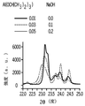
さらに、相エンベロープ(phase envelope)も作製するためにXRDを使用し、図3に示すように、縦軸に[AlO2/4]/[SiO2/4]をプロットし、横軸にNaOH/[SiO2/4]をプロットした。ダイアグラムは、MFI型ゼオライトは相空間の小さな領域にのみ形成されることを確認した。比較的低濃度の水酸化ナトリウム(すなわちSi/Na〜5)およびアルミニウム(すなわちSi/Al〜25)を有する溶液は、純粋なMFI型生成物をもたらすことを見出した。水酸化ナトリウムおよびアルミナのより低い濃度は、図3に示すように、未知物質および比較的重要な濃度の非晶質相を含んだいくつかの混合相生成物を与えることを見出した。
Further, by using the XRD for also making phase envelope (phase envelope), as shown in FIG. 3, the vertical axis plots the [AlO 2/4] / [
図4Aおよび4Bの得られたESEM顕微鏡写真を使用して、粒径を測定し、合成試料の表面形態を決定した。図4Aおよび4Bに示すように、生成されたMFIゼオライトがナノサイズの粒子またはマイクロサイズの粒子であるか否かを示すために、選択試料を分析した。選択試料の平均粒径測定値を表8に示す。
任意の新しく合成されたゼオライトの熱重量分析(TGA)分析は、HSFCCプロセスに典型的な500〜750℃の温度範囲に触媒は耐えなければならないため、重要なキャラクタリゼーションである。合成ゼオライトの水およびテトラプロピルアンモニウム(TPA+)含有量は、加熱時の重量減少から計算した。25〜200℃での重量減少は、ゼオライトからの水分の脱着によるものであった。25〜200℃で脱着した水は、ゼオライト中のナトリウム含有量に比例することが観察された。対照的に、試料中のTPA+が多いほど、加熱プロセスにおいて試料から脱離する水が少なくなる。これは、TPA+がナトリウムイオンに比べて比較的大きいという事実に起因する。TPA+は、水分子がゼオライト試料内部に吸着されるのを防止する疎水性を有する。さらに、TPA+は、水がゼオライトに付着するための空間を残さずにミクロ細孔(microspore)の大部分を満たす(表9参照)。 Thermogravimetric analysis (TGA) analysis of any newly synthesized zeolite is an important characterization as the catalyst must withstand the temperature range of 500-750 ° C. typical of the HSFCC process. The water and tetrapropylammonium (TPA +) content of the synthetic zeolite was calculated from the weight loss during heating. The weight loss at 25-200 ° C. was due to the desorption of water from the zeolite. It was observed that the water desorbed at 25-200 ° C. was proportional to the sodium content in the zeolite. In contrast, the higher the TPA + in the sample, the less water will be desorbed from the sample during the heating process. This is due to the fact that TPA + is relatively large compared to sodium ions. TPA + has a hydrophobic property that prevents water molecules from being adsorbed inside the zeolite sample. In addition, TPA + fills most of the microspores without leaving space for water to adhere to the zeolite (see Table 9).
より高い温度、200〜550℃では、TPA+はトリプロピルアンモニアに転化し、プロピレン分子を放出する。これは、図5Aおよび5Bに提示されている重量減少を生じさせる。TGAトレースから、単位格子構造に欠陥がないと仮定して単位格子あたりのTPA原子の数を計算することができる。欠陥がない理想的なMFI型ゼオライトは、以下の分子式(|TPAn|[AlnSi96−nO182])を有する。したがって、TPA+の数は、表9に示すように、重量減少率およびMFI型ゼオライトの分子式を用いて計算することができる。
図6Aおよび図6Bを参照。高ケイ酸塩試料および低ケイ酸塩試料(高アルミナ)に関する温度プログラムされた脱着曲線を収集した。16、17、および18の質量/電荷曲線はそれぞれ、NH2+、NH3+、H2O+イオンに対応している。高シリカ試料は、異なるエネルギーを有する2つのピークを示した。低エネルギーピークは109℃で生じ、弱く結合されたアンモニアに起因していた。この低エネルギー(低温)ピークは、アンモニアが物理吸着されたシラノール基の存在を示唆している。350℃でのピークは高エネルギーピークであり、それは、強ブレンステッド酸部位に強く結合されたアンモニアを示している。高アルミナ試料に関する225℃および400℃の2つのピークに分裂された信号が200〜500℃で観察された。これらのピークは、高シリカ試料について検出されたピークよりもエネルギーが高かった。それらは、触媒中に存在するブレンステッド活性部位に起因するものであり、より活性な部位が存在すれば、より良好な分解を付与することができる。結論として、試料中にアルミナがより多く存在すると、ブレンステッド酸部位がより多くなり、アンモニアに結合されるシラノール基はより少なくなって、より高温においてピークが生じた。 See FIGS. 6A and 6B. Temperature programmed desorption curves for high silicate and low silicate samples (high alumina) were collected. 16, 17, and 18 respectively mass / charge curves of, NH 2 +, NH 3 + , which corresponds to H 2 O + ions. The high silica sample showed two peaks with different energies. The low energy peak occurred at 109 ° C. and was due to weakly bound ammonia. This low energy (low temperature) peak suggests the presence of silanol groups on which ammonia is physically adsorbed. The peak at 350 ° C. is a high energy peak, indicating ammonia strongly bound to the strong Bronsted acid moiety. A signal split into two peaks at 225 ° C and 400 ° C for the high alumina sample was observed at 200-500 ° C. These peaks had higher energies than the peaks detected for high silica samples. They are due to the Bronsted active site present in the catalyst, and the presence of a more active site can confer better degradation. In conclusion, the more alumina present in the sample, the more Bronsted acid moieties, the fewer silanol groups bound to ammonia, and the peaks at higher temperatures.
Yゼオライトのキャラクタリゼーション
上記したように、ランタンで含浸されたUSYゼオライトは、軽質オレフィンに対する選択性に影響を及ぼす。しかしながら、図7Aおよび8Aそれぞれに示されているように、親Yゼオライトおよび含浸YゼオライトのESEM分析ではそれぞれ、親ゼオライトの組織分布的特徴(topographical feature)に変化は認められなかった。一方、ESEM内に組み込まれたEDS検出器を用いた元素分析は、ゼオライト試料が、図8Bに示した含浸されたYゼオライトのためのランタンに加えて、主としてケイ素、アルミニウム、および酸素から構成されていることを示した。
Characterization of Y Zeolites As mentioned above, USY zeolites impregnated with lanterns affect selectivity for light olefins. However, as shown in FIGS. 7A and 8A, the ESEM analysis of the parent Y-zeolite and the impregnated Y-zeolite showed no change in the topographical features of the parent zeolite, respectively. On the other hand, in the elemental analysis using the EDS detector incorporated in the ESEM, the zeolite sample is mainly composed of silicon, aluminum, and oxygen in addition to the lanthanum for the impregnated Y zeolite shown in FIG. 8B. I showed that.
図9に示すように、XRD分析を使用して、親Yゼオライトの結晶構造に及ぼすランタン含浸の効果を調べた。ゼオライトの親形態および含浸形態の回折図は、同一であり、したがって、図9に示すように、結晶構造に及ぼす効果は無かったことを示している。さらに、表面積および細孔容積分析(表10参照)により、Yゼオライトとその含浸形態との間に無視できる相違が存在する、ことが明らかになった。
特許請求される主題の趣旨および範囲から逸脱することなく、記載した実施形態に対して様々な修正および変更をなし得ることは、当業者には明らかである。したがって、添付の請求項およびそれらの請求項の等価物の範囲に含まれるならば、本明細書は、様々な記載した実施形態の修正および変更を包含することが意図される。
以下、本発明の好ましい実施形態を項分け記載する。
実施形態1
ガスコンデンセートを、プロピレンを含む生成物流に転化する方法であって、
ダウンフロー高過酷度流動接触分解反応器(HSFCC)の上部領域に少なくとも50重量%のパラフィンを含むガスコンデンセートを供給することと、
約5:1〜約40:1の触媒対ガスコンデンセート重量比によって特徴付けられる量でダウンフローHSFCC反応器の上部領域に触媒を供給することであって、前記触媒は、0.01〜0.2μmの平均粒径、20〜40のSi/Alモル比、および少なくとも20cm 2 /gの表面積を有するナノZSM−5ゼオライト触媒を含む、触媒を供給することと、
約500℃〜約700℃の反応温度において触媒の存在下で前記ガスコンデンセートを分解してプロピレンを含む前記生成物流を生成することと、
を含む、方法。
実施形態2
前記ダウンフローHSFCC反応器の前記上部領域に蒸気を添加することをさらに含む、実施形態1に記載の方法。
実施形態3
前記分解が、約1〜2atmの圧力で起こって、プロピレンを含む前記生成物流を生成する、実施形態1〜2のいずれかに記載の方法。
実施形態4
前記ガスコンデンセートが、0.1重量%未満のオレフィンを含む、実施形態1〜3のいずれかに記載の方法。
実施形態5
前記Si/Al原子比が、25〜35である、実施形態1〜4のいずれかに記載の方法。
実施形態6
前記生成物流が、少なくとも20重量%収率のプロピレンを含む、実施形態1〜5のいずれかに記載の方法。
実施形態7
前記生成物流が、少なくとも10重量%収率のエチレンを含む、実施形態1〜6のいずれかに記載の方法。
実施形態8
前記ナノZSM−5触媒が、リンで含浸される、実施形態1〜7のいずれかに記載の方法。
実施形態9
前記触媒が、10〜50重量%のナノZSM−5触媒を含む、実施形態1〜8のいずれかに記載の方法。
実施形態10
前記触媒が、USY(超安定Yゼオライト)を含む、実施形態1〜9のいずれかに記載の方法。
実施形態11
前記USY触媒が、ランタンで含浸される、実施形態10に記載の方法。
実施形態12
前記触媒が、10〜50重量%のUSY触媒を含む、実施形態1〜11のいずれかに記載の方法。
実施形態13
前記触媒が、アルミナ、粘土、およびシリカのうちの1つ以上を含む、実施形態1〜12のいずれかに記載の方法。
実施形態14
前記粘土が、カオリン、モンモリロナイト、ハロイサイト、およびベントナイトから選択される1つ以上の成分を含む、実施形態13に記載の方法。
実施形態15
前記触媒が、30〜70重量%の粘土を含む、実施形態1〜14のいずれかに記載の方法。
実施形態16
前記触媒が、2〜20重量%のアルミナを含む、実施形態1〜15のいずれかに記載の方法。
実施形態17
前記触媒が、0.1〜10重量%のシリカを含む、実施形態1〜16のいずれかに記載の方法。
実施形態18
前記反応温度が、約550℃〜約630℃である、実施形態1〜17のいずれかに記載の方法。
実施形態19
前記ガスコンデンセートが、0.7秒〜10秒のダウンフロー流動接触分解反応器における滞留時間を有する、実施形態1〜18のいずれかに記載の方法。
実施形態20
前記触媒対ガスコンデンセートの比が、5:1〜約10:1である、実施形態1〜19のいずれかに記載の方法。
実施形態21
前記触媒が、ナノZSM−5触媒、USY触媒、アルミナ、粘土、およびシリカを含む、実施形態1〜20のいずれかに記載の方法。
実施形態22
前記触媒が、10〜50重量%のナノZSM−5触媒、10〜50重量%のUSY触媒、2〜20重量%のアルミナ、30〜70重量%の粘土、および0.1〜10重量%のシリカを含む、実施形態1〜21のいずれかに記載の方法。
実施形態23
前記ガスコンデンセートが、ナフテンおよび芳香族化合物を含む、実施形態1〜22のいずれかに記載の方法。
実施形態24
前記ガスコンデンセートが、65重量%のパラフィン、0重量%のオレフィン、21重量%のナフテン、および15重量%の芳香族化合物を含む、実施形態1〜23のいずれかに記載の方法。
実施形態25
前記ガスコンデンセートが、真沸点分析に従って測定すると、少なくとも0℃の初期沸点および少なくとも450℃の最終沸点を有する、実施形態1〜24のいずれかに記載の方法。
実施形態26
前記ナノZSM−5ゼオライトが、少なくとも30cm 2 /gの表面積を有する、実施形態1〜25のいずれかに記載の方法。
実施形態27
前記ガスコンデンセートが、ASTM 2699またはASTM 2700によると70〜75のリサーチ法オクタン価(RON)を有する、実施形態1〜26のいずれかに記載の方法。
It will be apparent to those skilled in the art that various modifications and changes can be made to the described embodiments without departing from the spirit and scope of the claimed subject matter. Accordingly, as included in the appended claims and their equivalents, the present specification is intended to include modifications and modifications of various described embodiments.
Hereinafter, preferred embodiments of the present invention will be described in terms of terms.
Embodiment 1
It is a method of converting gas condensate into a product distribution containing propylene.
To supply a gas condensate containing at least 50% by weight of paraffin to the upper region of a downflow high severity fluid cracking reactor (HSFCC).
Feeding the catalyst into the upper region of the downflow HSFCC reactor in an amount characterized by a catalyst-to-gas-condensate weight ratio of about 5: 1 to about 40: 1, said catalyst is 0.01-0. Supplying a catalyst comprising a nano-ZSM-5 zeolite catalyst having an average particle size of 2 μm, a Si / Al molar ratio of 20-40, and a surface area of at least 20 cm 2 / g.
Decomposing the gas condensate in the presence of a catalyst at a reaction temperature of about 500 ° C to about 700 ° C to produce the product stream containing propylene.
Including methods.
The method of embodiment 1, further comprising adding steam to the upper region of the downflow HSFCC reactor.
The method according to any one of embodiments 1-2, wherein the decomposition occurs at a pressure of about 1-2 atm to produce the product stream containing propylene.
The method according to any one of embodiments 1 to 3, wherein the gas condensate contains less than 0.1% by weight of an olefin.
The method according to any one of embodiments 1 to 4, wherein the Si / Al atomic ratio is 25 to 35.
The method according to any of embodiments 1-5, wherein the product stream comprises at least 20% by weight propylene.
Embodiment 7
The method according to any of embodiments 1-6, wherein the product stream comprises at least 10% by weight of ethylene.
8th Embodiment
The method according to any of embodiments 1-7, wherein the nano-ZSM-5 catalyst is impregnated with phosphorus.
Embodiment 9
The method according to any of embodiments 1-8, wherein the catalyst comprises 10-50% by weight of a nano ZSM-5 catalyst.
The method according to any of embodiments 1-9, wherein the catalyst comprises USY (ultra-stable Y zeolite).
Embodiment 11
10. The method of
The method according to any of embodiments 1-11, wherein the catalyst comprises 10-50% by weight of USY catalyst.
Embodiment 13
The method according to any of embodiments 1-12, wherein the catalyst comprises one or more of alumina, clay, and silica.
13. The method of embodiment 13, wherein the clay comprises one or more components selected from kaolin, montmorillonite, halloysite, and bentonite.
Embodiment 15
The method according to any of embodiments 1-14, wherein the catalyst comprises 30-70% by weight clay.
The method according to any of embodiments 1-15, wherein the catalyst comprises 2-20% by weight of alumina.
The method according to any of embodiments 1-16, wherein the catalyst comprises 0.1 to 10% by weight silica.
The method according to any of embodiments 1-17, wherein the reaction temperature is from about 550 ° C to about 630 ° C.
Embodiment 19
The method according to any of embodiments 1-18, wherein the gas condensate has a residence time in a downflow flow catalytic cracking reactor of 0.7 to 10 seconds.
20th embodiment
The method according to any of embodiments 1-19, wherein the catalyst to gas condensate ratio is 5: 1 to about 10: 1.
21st embodiment
The method according to any of embodiments 1-20, wherein the catalyst comprises a nano-ZSM-5 catalyst, a USY catalyst, alumina, clay, and silica.
Embodiment 22
The catalysts are 10-50% by weight nano-ZSM-5 catalyst, 10-50% by weight USY catalyst, 2-20% by weight alumina, 30-70% by weight clay, and 0.1-10% by weight. The method according to any of embodiments 1-21, comprising silica.
23rd Embodiment
The method according to any of embodiments 1 to 22, wherein the gas condensate comprises naphthene and an aromatic compound.
Embodiment 24
The method of any of embodiments 1-23, wherein the gas condensate comprises 65% by weight paraffin, 0% by weight olefin, 21% by weight naphthene, and 15% by weight aromatic compound.
25.
The method according to any of embodiments 1-24, wherein the gas condensate has an initial boiling point of at least 0 ° C. and a final boiling point of at least 450 ° C. as measured according to true boiling point analysis.
Embodiment 26
The method according to any of embodiments 1-25, wherein the nano ZSM-5 zeolite has a surface area of at least 30 cm 2 / g.
Embodiment 27
The method according to any of embodiments 1-26, wherein the gas condensate has a research octane number (RON) of 70-75 according to ASTM 2699 or ASTM 2700.
Claims (14)
ダウンフロー高過酷度流動接触分解反応器(HSFCC)の上部領域に少なくとも50重量%のパラフィンを含むガスコンデンセートを供給することと、
5:1〜40:1の触媒対ガスコンデンセート重量比によって特徴付けられる量でダウンフローHSFCC反応器の上部領域に触媒を供給することであって、前記触媒は、0.01〜0.2μmの平均粒径、20〜40のSi/Alモル比、および少なくとも20cm2/gの表面積を有するナノZSM−5ゼオライト触媒を含む、触媒を供給することと、
500℃〜700℃の反応温度において触媒の存在下で前記ガスコンデンセートを分解してプロピレンを含む前記生成物流を生成することと、
を含み、
前記触媒が、10〜50重量%のナノZSM−5触媒を含む、方法。 It is a method of converting gas condensate into a product distribution containing propylene.
To supply a gas condensate containing at least 50% by weight of paraffin to the upper region of a downflow high severity fluid cracking reactor (HSFCC).
Feeding the catalyst into the upper region of the downflow ZSFCC reactor in an amount characterized by a catalyst to gas condensation weight ratio of 5 : 1 to 40: 1, said catalyst is 0.01 to 0.2 μm. Supplying a catalyst comprising a nano-ZSM-5 zeolite catalyst having an average particle size of 20-40 Si / Al molar ratio and a surface area of at least 20 cm 2 / g.
And generating said product stream comprising propylene at 5 00 ℃ ~7 00 ℃ reaction temperature in the presence of a catalyst to decompose the gas condensate,
Only including,
A method in which the catalyst comprises 10-50% by weight of a nano ZSM-5 catalyst.
Applications Claiming Priority (3)
| Application Number | Priority Date | Filing Date | Title |
|---|---|---|---|
| US15/190,327 US9981888B2 (en) | 2016-06-23 | 2016-06-23 | Processes for high severity fluid catalytic cracking systems |
| US15/190,327 | 2016-06-23 | ||
| PCT/US2017/038740 WO2017223310A1 (en) | 2016-06-23 | 2017-06-22 | Processes for high severity fluid catalytic cracking systems |
Publications (3)
| Publication Number | Publication Date |
|---|---|
| JP2019524914A JP2019524914A (en) | 2019-09-05 |
| JP2019524914A5 JP2019524914A5 (en) | 2020-07-30 |
| JP6959269B2 true JP6959269B2 (en) | 2021-11-02 |
Family
ID=59399470
Family Applications (1)
| Application Number | Title | Priority Date | Filing Date |
|---|---|---|---|
| JP2018566445A Active JP6959269B2 (en) | 2016-06-23 | 2017-06-22 | Process for High Severity Flow Contact Cracking Systems |
Country Status (7)
| Country | Link |
|---|---|
| US (2) | US9981888B2 (en) |
| EP (1) | EP3475393B1 (en) |
| JP (1) | JP6959269B2 (en) |
| KR (1) | KR102431019B1 (en) |
| CN (1) | CN109415635B (en) |
| SG (2) | SG11201811402SA (en) |
| WO (1) | WO2017223310A1 (en) |
Families Citing this family (20)
| Publication number | Priority date | Publication date | Assignee | Title |
|---|---|---|---|---|
| CN110724550B (en) | 2018-07-16 | 2021-04-06 | 中国石油化工股份有限公司 | Method and system for catalytic cracking by adopting fast fluidized bed |
| CN110724553B (en) | 2018-07-16 | 2021-04-06 | 中国石油化工股份有限公司 | Method and system for catalytic cracking by adopting dilute phase conveying bed and rapid fluidized bed |
| CN111607425B (en) * | 2019-02-26 | 2022-03-29 | 中国石油天然气股份有限公司 | Method for catalytic cracking of straight-run diesel oil |
| CN114364770A (en) * | 2019-08-05 | 2022-04-15 | 沙特基础工业全球技术公司 | Process for the catalytic cracking of hydrocarbons to produce olefins and aromatics without steam as diluent |
| US11066606B2 (en) * | 2019-11-12 | 2021-07-20 | Saudi Arabian Oil Company | Systems and methods for catalytic upgrading of vacuum residue to distillate fractions and olefins with steam |
| US11066605B2 (en) | 2019-11-12 | 2021-07-20 | Saudi Arabian Oil Company | Systems and methods for catalytic upgrading of vacuum residue to distillate fractions and olefins |
| JP7508816B2 (en) * | 2020-03-13 | 2024-07-02 | 東ソー株式会社 | Olefin production catalyst |
| US11225612B2 (en) * | 2020-03-27 | 2022-01-18 | Saudi Arabian Oil Company | Catalyst and process for catalytic steam cracking of heavy distillate |
| US11213810B1 (en) | 2020-07-06 | 2022-01-04 | Saudi Arabian Oil Company | Method of producing a cracking catalyst |
| US11278873B2 (en) * | 2020-07-16 | 2022-03-22 | Saudi Arabian Oil Company | Method of producing an aromatization catalyst |
| US11370975B2 (en) | 2020-09-30 | 2022-06-28 | Saudi Arabian Oil Company | Steam-enhanced catalytic cracking of hydrocarbons to produce light olefins |
| US11370731B1 (en) * | 2021-01-12 | 2022-06-28 | Saudi Arabian Oil Company | Systems and processes for producing olefins from crude oil |
| WO2024006381A1 (en) * | 2022-06-29 | 2024-01-04 | W.R. Grace & Co.-Conn. | Fcc process useful for production of petrochemicals |
| US12012554B2 (en) * | 2022-07-06 | 2024-06-18 | Saudi Arabian Oil Company | Process and catalyst formulation for cracking crude oil to produce light olefins and aromatics |
| US11827855B1 (en) * | 2022-07-06 | 2023-11-28 | Saudi Arabian Oil Company | Process and nano-ZSM-5 based catalyst formulation for cracking crude oil to produce light olefins and aromatics |
| US11866651B1 (en) * | 2022-11-09 | 2024-01-09 | Saudi Arabian Oil Company | Process and catalyst formulation for cracking crude oil |
| US11866660B1 (en) | 2022-11-09 | 2024-01-09 | Saudi Arabian Oil Company | Process and catalyst formulation for cracking crude oil |
| US11814593B1 (en) * | 2022-12-12 | 2023-11-14 | Saudi Arabian Oil Company | Processes for hydroprocessing and cracking crude oil |
| US11814594B1 (en) * | 2022-12-12 | 2023-11-14 | Saudi Arabian Oil Company | Processes for hydroprocessing and cracking crude oil |
| US12018215B1 (en) * | 2023-04-12 | 2024-06-25 | Saudi Arabian Oil Company | Processes for direct conversion of crude oil to light olefins and light aromatics through steam enhanced catalytic cracking over a core shell cracking catalyst |
Family Cites Families (69)
| Publication number | Priority date | Publication date | Assignee | Title |
|---|---|---|---|---|
| US3837822A (en) | 1972-09-28 | 1974-09-24 | Universal Oil Prod Co | Two-stage countercurrent fluid-solid contacting process |
| CN1004878B (en) | 1987-08-08 | 1989-07-26 | 中国石油化工总公司 | Hydrocarbon catalytic conversion method for preparing low-carbon olefin |
| US5043522A (en) | 1989-04-25 | 1991-08-27 | Arco Chemical Technology, Inc. | Production of olefins from a mixture of Cu+ olefins and paraffins |
| US5026936A (en) | 1989-10-02 | 1991-06-25 | Arco Chemical Technology, Inc. | Enhanced production of propylene from higher hydrocarbons |
| US5026935A (en) | 1989-10-02 | 1991-06-25 | Arco Chemical Technology, Inc. | Enhanced production of ethylene from higher hydrocarbons |
| US5160424A (en) | 1989-11-29 | 1992-11-03 | Mobil Oil Corporation | Hydrocarbon cracking, dehydrogenation and etherification process |
| US5171921A (en) | 1991-04-26 | 1992-12-15 | Arco Chemical Technology, L.P. | Production of olefins |
| US5232580A (en) | 1991-06-21 | 1993-08-03 | Mobil Oil Corporation | Catalytic process for hydrocarbon cracking using synthetic mesoporous crystalline material |
| CN1029407C (en) * | 1992-07-16 | 1995-08-02 | 中国石油化工总公司 | Catalytic cracking method for adaptable multieffect hydrocarbons |
| US5318689A (en) | 1992-11-16 | 1994-06-07 | Texaco Inc. | Heavy naphtha conversion process |
| JPH06192135A (en) * | 1992-12-25 | 1994-07-12 | Asahi Chem Ind Co Ltd | Method for converting light hydrocarbon |
| US5523502A (en) | 1993-11-10 | 1996-06-04 | Stone & Webster Engineering Corp. | Flexible light olefins production |
| US5770042A (en) | 1993-11-15 | 1998-06-23 | Uop | Upgrading of cyclic naphthas |
| US5549813A (en) | 1994-03-07 | 1996-08-27 | Dai; Pei-Shing E. | FCC process employing low unit cell size y-zeolites |
| AU4737896A (en) | 1994-11-23 | 1996-06-17 | Exxon Chemical Patents Inc. | Hydrocarbon conversion process using a zeolite bound zeolite catalyst |
| US5637207A (en) | 1995-04-14 | 1997-06-10 | Abb Lummus Global Inc. | Fluid catalytic cracking process |
| US5685972A (en) | 1995-07-14 | 1997-11-11 | Timken; Hye Kyung C. | Production of benzene, toluene, and xylene (BTX) from FCC naphtha |
| EP0909804B1 (en) | 1997-10-15 | 2010-09-08 | China Petro-Chemical Corporation | A process for production of ethylene and propylene by catalytic pyrolysis of heavy hydrocarbons |
| US5976356A (en) | 1997-11-12 | 1999-11-02 | Phillips Petroleum Company | Acid treated zeolite containing boron and silver used as a catalyst for converting hydrocarbons and a method of making and using such catalyst |
| EP0921179A1 (en) | 1997-12-05 | 1999-06-09 | Fina Research S.A. | Production of olefins |
| US6315890B1 (en) | 1998-05-05 | 2001-11-13 | Exxonmobil Chemical Patents Inc. | Naphtha cracking and hydroprocessing process for low emissions, high octane fuels |
| AU744826B2 (en) | 1998-05-05 | 2002-03-07 | Exxonmobil Chemical Patents Inc | Hydrocarbon conversion to propylene with high silica medium pore zeolite catalysts |
| US6069287A (en) | 1998-05-05 | 2000-05-30 | Exxon Research And Engineering Co. | Process for selectively producing light olefins in a fluid catalytic cracking process |
| US6455750B1 (en) | 1998-05-05 | 2002-09-24 | Exxonmobil Chemical Patents Inc. | Process for selectively producing light olefins |
| US6602403B1 (en) | 1998-05-05 | 2003-08-05 | Exxonmobil Chemical Patents Inc. | Process for selectively producing high octane naphtha |
| US6294493B1 (en) | 1998-05-26 | 2001-09-25 | Exxon Mobil Chemical Patents Inc. | Silicoaluminophosphates having an AEL structure |
| US6015933A (en) | 1998-07-15 | 2000-01-18 | Uop Llc | Process for removing polymeric by-products from acetylene hydrogenation product |
| EP1117750B1 (en) | 1998-09-28 | 2004-06-30 | BP Corporation North America Inc. | Process for manufacturing olefins using a pentasil zeolite based catalyst |
| US20020003103A1 (en) | 1998-12-30 | 2002-01-10 | B. Erik Henry | Fluid cat cracking with high olefins prouduction |
| EP1116775A1 (en) | 2000-01-12 | 2001-07-18 | Akzo Nobel N.V. | Catalyst composition with high efficiency for the production of light olefins |
| US20010042700A1 (en) | 2000-04-17 | 2001-11-22 | Swan, George A. | Naphtha and cycle oil conversion process |
| US6652737B2 (en) | 2000-07-21 | 2003-11-25 | Exxonmobil Research And Engineering Company | Production of naphtha and light olefins |
| US6784329B2 (en) | 2002-01-14 | 2004-08-31 | Chevron U.S.A. Inc. | Olefin production from low sulfur hydrocarbon fractions |
| DE10217863A1 (en) | 2002-04-22 | 2003-10-30 | Linde Ag | Process and apparatus for olefin production |
| KR100972705B1 (en) | 2002-06-28 | 2010-07-28 | 알베마를 네덜란드 비.브이. | Fcc catalyst for reducing the sulfur content in gasoline and diesel |
| US6867341B1 (en) | 2002-09-17 | 2005-03-15 | Uop Llc | Catalytic naphtha cracking catalyst and process |
| US7270739B2 (en) | 2003-02-28 | 2007-09-18 | Exxonmobil Research And Engineering Company | Fractionating and further cracking a C6 fraction from a naphtha feed for propylene generation |
| US7273543B2 (en) * | 2003-08-04 | 2007-09-25 | Stone & Webster Process Technology, Inc. | Process and apparatus for controlling catalyst temperature in a catalyst stripper |
| US7326332B2 (en) | 2003-09-25 | 2008-02-05 | Exxonmobil Chemical Patents Inc. | Multi component catalyst and its use in catalytic cracking |
| US7128827B2 (en) | 2004-01-14 | 2006-10-31 | Kellogg Brown & Root Llc | Integrated catalytic cracking and steam pyrolysis process for olefins |
| KR100632563B1 (en) | 2004-09-10 | 2006-10-09 | 에스케이 주식회사 | Solid acid catalyst for catalytic cracking and process for selectively preparing light olefins from full range naphtha |
| US7374660B2 (en) | 2004-11-19 | 2008-05-20 | Exxonmobil Chemical Patents Inc. | Process for selectively producing C3 olefins in a fluid catalytic cracking process with recycle of a C4 fraction to a secondary reaction zone separate from a dense bed stripping zone |
| US7323099B2 (en) | 2004-11-19 | 2008-01-29 | Exxonmobil Chemical Patents Inc. | Two stage fluid catalytic cracking process for selectively producing C2 to C4 olefins |
| US7459596B1 (en) | 2005-07-26 | 2008-12-02 | Uop Llc | Nanocrystalline silicalite for catalytic naphtha cracking |
| KR101270191B1 (en) | 2005-08-15 | 2013-05-31 | 상하이 리서치 인스티튜트 오브 페트로케미칼 테크놀로지 시노펙 | Method for preparation of ethylene and propylene by catalytic cracking using a fluid-bed catalyst |
| CN100391610C (en) * | 2005-08-15 | 2008-06-04 | 中国石油化工股份有限公司 | Catalytic cracking fluid bed catalyst containing molecular sieve |
| CA2657112A1 (en) * | 2006-07-26 | 2008-01-31 | Total Petrochemicals Research Feluy | Production of olefins |
| US7935654B2 (en) | 2006-09-28 | 2011-05-03 | Lg Chem, Ltd. | Oxide catalyst and phosphoric oxide catalyst for hydrocarbon steam cracking, method for preparing the same and method for preparing olefin by using the same |
| EA016421B1 (en) * | 2006-11-07 | 2012-04-30 | Сауди Арабиан Ойл Компани | Advanced control of severe fluid catalytic cracking process for maximizing propylene production from petroleum feedstock |
| US7727486B2 (en) * | 2007-08-01 | 2010-06-01 | Uop Llc | Apparatus for heating regeneration gas |
| CN101367699B (en) * | 2007-10-31 | 2012-05-09 | 陕西煤化工技术工程中心有限公司 | Preparation of propylene |
| US8652737B2 (en) | 2007-11-08 | 2014-02-18 | Canon Kabushiki Kaisha | Toner and image forming process |
| FR2932495B1 (en) * | 2008-06-17 | 2011-03-25 | Inst Francais Du Petrole | DEVICE FOR CONTROLLING OPERATIVE CONDITIONS IN A CATALYTIC CRACKING UNIT WITH TWO RISERS. |
| US8137533B2 (en) | 2008-10-24 | 2012-03-20 | Uop Llc | Mixture of catalysts for cracking naphtha to olefins |
| WO2010053482A1 (en) | 2008-11-06 | 2010-05-14 | Uop Llc | Nanocrystalline silicalite for catalytic naphtha cracking |
| BRPI0805207B1 (en) | 2008-11-25 | 2019-11-12 | Petroleo Brasileiro Sa Petrobras | catalytic cracking process of a hydrocarbon stream for maximizing light olefins |
| US8246914B2 (en) * | 2008-12-22 | 2012-08-21 | Uop Llc | Fluid catalytic cracking system |
| US20120024748A1 (en) * | 2009-03-30 | 2012-02-02 | Saravanan Subramani | Fluidized catalytic cracking process |
| WO2011115785A1 (en) | 2010-03-18 | 2011-09-22 | W. R. Grace & Co.-Conn. | High light olefins fcc catalyst compositions |
| US8247631B2 (en) | 2010-06-21 | 2012-08-21 | Uop Llc | Process for catalytic cracking of hydrocarbons using UZM-35 |
| US8524630B2 (en) * | 2010-10-08 | 2013-09-03 | Exxonmobil Research And Engineering Company | Mesoporous aluminas stabilized with rare earth and phosphorous |
| US9101853B2 (en) | 2011-03-23 | 2015-08-11 | Saudi Arabian Oil Company | Integrated hydrocracking and fluidized catalytic cracking system and process |
| AU2012369895B2 (en) * | 2012-02-14 | 2015-11-12 | Reliance Industries Ltd. | A process for catalytic conversion of low value hydrocarbon streams to light olefins |
| JP5977840B2 (en) | 2012-03-02 | 2016-08-24 | ペトロレオ ブラジレイロ ソシエダ アノニマ − ペトロブラス | Additives that maximize light olefins in fluid catalytic cracking and processing equipment. |
| JP6166344B2 (en) | 2012-03-20 | 2017-07-19 | サウジ アラビアン オイル カンパニー | Integrated hydroprocessing, steam pyrolysis, and catalytic cracking to produce petrochemicals from crude oil |
| CN103159579A (en) * | 2013-02-07 | 2013-06-19 | 大连理工大学 | Method of light alkane catalytic cracking by using modified molecular sieve catalyst |
| US8895790B2 (en) | 2013-02-12 | 2014-11-25 | Saudi Basic Industries Corporation | Conversion of plastics to olefin and aromatic products |
| WO2015084779A1 (en) | 2013-12-02 | 2015-06-11 | Saudi Arabian Oil Company | Integrated solvent-deasphalting and fluid catalytic cracking process for light olefin production |
| JP6329436B2 (en) * | 2014-05-30 | 2018-05-23 | Jxtgエネルギー株式会社 | Fluid catalytic cracking of heavy oil |
-
2016
- 2016-06-23 US US15/190,327 patent/US9981888B2/en active Active
-
2017
- 2017-06-22 EP EP17743414.9A patent/EP3475393B1/en active Active
- 2017-06-22 KR KR1020197002121A patent/KR102431019B1/en active IP Right Grant
- 2017-06-22 SG SG11201811402SA patent/SG11201811402SA/en unknown
- 2017-06-22 JP JP2018566445A patent/JP6959269B2/en active Active
- 2017-06-22 CN CN201780037661.3A patent/CN109415635B/en active Active
- 2017-06-22 WO PCT/US2017/038740 patent/WO2017223310A1/en unknown
- 2017-06-22 SG SG10201912689PA patent/SG10201912689PA/en unknown
-
2018
- 2018-05-01 US US15/967,665 patent/US10059642B1/en active Active
Also Published As
| Publication number | Publication date |
|---|---|
| CN109415635A (en) | 2019-03-01 |
| CN109415635B (en) | 2021-04-16 |
| KR20190020793A (en) | 2019-03-04 |
| KR102431019B1 (en) | 2022-08-11 |
| US9981888B2 (en) | 2018-05-29 |
| US10059642B1 (en) | 2018-08-28 |
| SG10201912689PA (en) | 2020-02-27 |
| EP3475393A1 (en) | 2019-05-01 |
| US20180244591A1 (en) | 2018-08-30 |
| EP3475393B1 (en) | 2020-03-11 |
| SG11201811402SA (en) | 2019-01-30 |
| JP2019524914A (en) | 2019-09-05 |
| WO2017223310A1 (en) | 2017-12-28 |
| US20170369397A1 (en) | 2017-12-28 |
Similar Documents
| Publication | Publication Date | Title |
|---|---|---|
| JP6959269B2 (en) | Process for High Severity Flow Contact Cracking Systems | |
| Su et al. | Synthesis of microscale and nanoscale ZSM-5 zeolites: effect of particle size and acidity of Zn modified ZSM-5 zeolites on aromatization performance | |
| García-Martínez et al. | Mesostructured zeolite Y—high hydrothermal stability and superior FCC catalytic performance | |
| CN112638525B (en) | Method for synthesizing multistage pore zeolite for catalytic cracking | |
| JP6710006B2 (en) | Fluid catalytic cracking method | |
| Gao et al. | Modified seeding method for preparing hierarchical nanocrystalline ZSM-5 catalysts for methanol aromatisation | |
| KR102262349B1 (en) | Catalyst compositions comprising small size molecular sieves crystals deposited on a porous material | |
| JP5873570B2 (en) | Catalyst for producing paraxylene by mixed conversion of methanol and / or dimethyl ether and C4 liquefied gas, and its production method and use | |
| Ding et al. | Catalytic properties of a hierarchical zeolite synthesized from a natural aluminosilicate mineral without the use of a secondary mesoscale template | |
| JP4740396B2 (en) | Process for producing aromatic hydrocarbons | |
| KR101790368B1 (en) | Catalyst for use in production of monocyclic aromatic hydrocarbon, and process for production of monocyclic aromatic hydrocarbon | |
| Ghashghaee et al. | Steam catalytic cracking of fuel oil over a novel composite nanocatalyst: characterization, kinetics and comparative perspective | |
| US9809507B2 (en) | Catalyst for producing monocyclic aromatic hydrocarbons, and method for producing monocyclic aromatic hydrocarbons | |
| US9815047B2 (en) | Catalyst for producing monocyclic aromatic hydrocarbon and production method of monocyclic aromatic hydrocarbon | |
| TW201029929A (en) | Novel ultra stable zeolite Y and method for manufacturing the same | |
| JP2001525780A (en) | Modified MCM-56, its production method and use | |
| Liu et al. | Zeolite Y synthesized with FCC spent catalyst fines: particle size effect on catalytic reactions | |
| JP2020032352A (en) | Fluid contact cracking catalyst for hydrocarbon oil | |
| JP2015187064A (en) | Zeolite molding | |
| KR20150135665A (en) | Catalyst for residue fluid catalytic cracking system having high yielding diesel and preparing method thereof | |
| JP2016175038A (en) | Zeolite molding | |
| US11938466B2 (en) | Catalyst systems and methods of synthesizing catalyst systems | |
| Ndlela et al. | Faujasite silicalites for oxidative dehydrogenation of n-octane: Influence of alkali metals, gallium, and boron on catalyst activity | |
| US20130267749A1 (en) | Catalyst for producing monocyclic aromatic hydrocarbons and production method of monocyclic aromatic hydrocarbons | |
| JP2010167349A (en) | Fluidized catalytic cracking catalyst for producing light olefin |
Legal Events
| Date | Code | Title | Description |
|---|---|---|---|
| A521 | Request for written amendment filed |
Free format text: JAPANESE INTERMEDIATE CODE: A523 Effective date: 20200622 |
|
| A621 | Written request for application examination |
Free format text: JAPANESE INTERMEDIATE CODE: A621 Effective date: 20200622 |
|
| A977 | Report on retrieval |
Free format text: JAPANESE INTERMEDIATE CODE: A971007 Effective date: 20210226 |
|
| A131 | Notification of reasons for refusal |
Free format text: JAPANESE INTERMEDIATE CODE: A131 Effective date: 20210303 |
|
| A521 | Request for written amendment filed |
Free format text: JAPANESE INTERMEDIATE CODE: A523 Effective date: 20210514 |
|
| TRDD | Decision of grant or rejection written | ||
| A01 | Written decision to grant a patent or to grant a registration (utility model) |
Free format text: JAPANESE INTERMEDIATE CODE: A01 Effective date: 20210908 |
|
| A61 | First payment of annual fees (during grant procedure) |
Free format text: JAPANESE INTERMEDIATE CODE: A61 Effective date: 20211007 |
|
| R150 | Certificate of patent or registration of utility model |
Ref document number: 6959269 Country of ref document: JP Free format text: JAPANESE INTERMEDIATE CODE: R150 |