JP6957848B2 - How to initialize electronic devices and DRAM - Google Patents
How to initialize electronic devices and DRAM Download PDFInfo
- Publication number
- JP6957848B2 JP6957848B2 JP2016187345A JP2016187345A JP6957848B2 JP 6957848 B2 JP6957848 B2 JP 6957848B2 JP 2016187345 A JP2016187345 A JP 2016187345A JP 2016187345 A JP2016187345 A JP 2016187345A JP 6957848 B2 JP6957848 B2 JP 6957848B2
- Authority
- JP
- Japan
- Prior art keywords
- dram
- reset
- control unit
- rank mode
- cpu
- Prior art date
- Legal status (The legal status is an assumption and is not a legal conclusion. Google has not performed a legal analysis and makes no representation as to the accuracy of the status listed.)
- Active
Links
- 238000000034 method Methods 0.000 claims description 11
- 230000004044 response Effects 0.000 claims description 9
- 230000008859 change Effects 0.000 claims description 4
- 238000010586 diagram Methods 0.000 description 7
- 230000006870 function Effects 0.000 description 3
- 230000007257 malfunction Effects 0.000 description 3
- 230000009977 dual effect Effects 0.000 description 2
- 230000008569 process Effects 0.000 description 2
- 238000011084 recovery Methods 0.000 description 2
- 230000007704 transition Effects 0.000 description 1
Images

Landscapes
- Memory System (AREA)
- Dram (AREA)
Description
本発明は、電子装置およびDRAMの初期化方法に関する。 The present invention relates to methods for initializing electronic devices and DRAMs.
特許文献1には、省電力モードからの復帰時に、揮発性メモリに記憶されている信頼性の高い情報を利用可能なメモリ制御装置が開示されている。このメモリ制御装置において、SDRAMコントローラは、省電力モードに移行するときに、SDRAMコントローラ内に設定されている情報をSDRAMに記憶した後にSDRAMをセルフリフレッシュモードに移行させ、省エネ復帰認識回路に省電力モードを示す情報を記憶させる。そして、電力供給が開始されたときに、省エネ復帰認識回路に記憶されている情報に基づいて省電力モードからの復帰か否かを判別し、装置全体への電力供給が停止された状態から復帰を判別した場合には、SDRAMを初期化し、省電力モードからの復帰を判別した場合には、SDRAMを初期化せずにSDRAMのセルフリフレッシュモードを解除した後にSDRAMに記憶されている情報に基づいて省電力モードからの復帰処理を行う。
DDR3(Double-Data-Rate3)以降の規格によるDRAM(Dynamic Random Access Memory)では、リセット機能が設けられており、電源投入時等の初期化手順(初期化シーケンス)等の場面で必要に応じてリセット操作が行われる。一方、省電力設計においては、CPUへの電源供給を停止するモードが設定される場合がある。この場合、CPUが電源OFFの状態でもDRAMに対するリセット制御を可能とするため、DRAMのリセット制御用の外部装置が設けられる。しかし、このような構成では、DRAMのリセット制御をCPUに代わって外部装置が行うため、CPUが直接リセット操作を行う場合と異なり、操作によっては動作不良が生じる場合があった。 DRAM (Dynamic Random Access Memory) based on DDR3 (Double-Data-Rate3) or later standards is provided with a reset function, and is required for initialization procedures (initialization sequence) such as when the power is turned on. A reset operation is performed. On the other hand, in the power saving design, a mode for stopping the power supply to the CPU may be set. In this case, in order to enable reset control for the DRAM even when the power is off, an external device for reset control of the DRAM is provided. However, in such a configuration, since the reset control of the DRAM is performed by an external device instead of the CPU, a malfunction may occur depending on the operation, unlike the case where the CPU directly performs the reset operation.
本発明は、CPUに代わって外部装置によりDRAMのリセット制御を行う構成において、リセット操作における動作不良の発生を抑制することを目的とする。 An object of the present invention is to suppress the occurrence of malfunction in the reset operation in a configuration in which a DRAM reset control is performed by an external device instead of the CPU.
本発明の請求項1に係る電子装置は、
リセットが可能なDRAMと、
前記DRAMのリセット制御を行うリセット制御部と、
前記DRAMに対するアクセス制御を行うと共に、当該DRAMに対するリセット操作を前記リセット制御部に依頼するDRAM制御部と、を備え、
前記リセット制御部は、予め設定された条件に基づいて前記DRAMのリセット操作を行うと共に、前記DRAM制御部からの依頼に応じて当該DRAMのリセットおよびリセット解除を行い、
前記DRAM制御部は、電源供給を開始された際の動作として、
シングルランク・モードで前記DRAMに対する初期化シーケンスを実行して当該DRAMに対するアクセスのタイミング調整を行い、
次に、前記リセット制御部に当該DRAMのリセットを依頼し、当該シングルランク・モードからマルチランク・モードに変更した後に、当該リセット制御部に当該DRAMのリセット解除を依頼し、
当該マルチランク・モードで当該DRAMに対する初期化シーケンスを実行することを特徴とする、電子装置である。
請求項2に係る電子装置は、
前記リセット制御部は、前記DRAM制御部に電源供給が開始されると、前記DRAMのリセット解除を行い、
前記DRAM制御部は、前記リセット制御部による前記DRAMのリセット解除が行われた後に、当該DRAMに対する初期化シーケンスを実行することを特徴とする、請求項1に記載の電子装置である。
請求項3に係る装置は、
リセットが可能なDRAM(ダイナミック・ランダム・アクセス・メモリ)に対するアクセス制御を行う装置であって、
電源供給を開始されると、シングルランク・モードで動作して、前記DRAMに対するアクセスのタイミング調整を行い、
前記DRAMのリセット制御を行う外部装置に当該DRAMをリセットさせ、リセット解除後に、マルチランク・モードで前記DRAMに対する初期化シーケンスを実行することを特徴とする、装置である。
請求項4に係るDRAMの初期化方法は、
リセットが可能なDRAMに対してアクセス制御を行うDRAM制御部による当該DRAMの初期化方法であって、
シングルランク・モードで前記DRAMに対する初期化シーケンスを実行して当該DRAMに対するアクセスのタイミング調整を行い、
前記DRAMのリセット制御を行う外部装置に、当該DRAMのリセットを依頼し、
前記シングルランク・モードからマルチランク・モードに変更し、
前記外部装置に、前記DRAMのリセット解除を依頼し、
前記マルチランク・モードで前記DRAMに対する初期化シーケンスを実行することを特徴とする、DRAMの初期化方法である。
The electronic device according to
DRAM that can be reset and
A reset control unit that controls the reset of the DRAM,
It is provided with a DRAM control unit that controls access to the DRAM and requests the reset control unit to perform a reset operation on the DRAM.
The reset control unit performs a reset operation of the DRAM based on preset conditions, and also resets and releases the DRAM in response to a request from the DRAM control unit.
The DRAM control unit operates as an operation when the power supply is started.
The initialization sequence for the DRAM is executed in the single rank mode to adjust the timing of access to the DRAM.
Next, the reset control unit is requested to reset the DRAM, and after changing from the single rank mode to the multi-rank mode, the reset control unit is requested to release the reset of the DRAM.
It is an electronic device characterized by executing an initialization sequence for the DRAM in the multi-rank mode.
The electronic device according to claim 2 is
When the power supply to the DRAM control unit is started, the reset control unit resets and releases the DRAM.
The electronic device according to
The device according to claim 3 is
A device that controls access to a resettable DRAM (Dynamic Random Access Memory).
When the power supply is started, it operates in the single rank mode, adjusts the timing of access to the DRAM, and adjusts the timing of access to the DRAM.
The apparatus is characterized in that an external device that performs reset control of the DRAM resets the DRAM, and after the reset is released, an initialization sequence for the DRAM is executed in a multi-rank mode.
The method for initializing the DRAM according to claim 4 is
A method for initializing a DRAM by a DRAM control unit that controls access to a resettable DRAM.
The initialization sequence for the DRAM is executed in the single rank mode to adjust the timing of access to the DRAM.
A request is made to an external device that controls the reset of the DRAM to reset the DRAM.
Change from the single rank mode to the multi rank mode
Request the external device to reset and release the DRAM,
A method for initializing a DRAM, which comprises executing an initialization sequence for the DRAM in the multi-rank mode.
請求項1の発明によれば、DRAM制御部に代わって外部装置によりDRAMのリセット制御を行う構成において、シングルランク・モードでDRAMに対するレベリングを行い、マルチランク・モードでDRAMを使用するDRAM制御部の電源供給開始時に行われる動作により、DRAM制御部がDRAMにとって不定状態となることを回避することができる。
請求項2の発明によれば、DRAMのリセットが解除されてからDRAM制御部の電源供給開始時の動作が開始されるように制御することにより、DRAM制御部によるDRAMの初期化シーケンスを確実に実行することができる。
請求項3の発明によれば、シングルランク・モードでDRAMに対するレベリングを行い、マルチランク・モードでDRAMを使用する装置の電源供給開始時に行われる動作において、装置がDRAMにとって不定状態となることを回避することができる。
請求項4の発明によれば、DRAMの初期化処理において、シングルランク・モードでDRAMに対するレベリングを行い、マルチランク・モードでDRAMを使用するDRAM制御部の電源供給開始時に行われる動作により、DRAM制御部がDRAMにとって不定状態となることを回避し、リセット操作における動作不良の発生を抑制することができる。
According to the first aspect of the present invention, in a configuration in which a DRAM reset control is performed by an external device instead of the DRAM control unit, the DRAM control unit performs leveling with respect to the DRAM in the single rank mode and uses the DRAM in the multi-rank mode. It is possible to prevent the DRAM control unit from being in an indefinite state for the DRAM by the operation performed at the start of power supply.
According to the invention of claim 2, by controlling so that the operation at the start of power supply of the DRAM control unit is started after the reset of the DRAM is released, the initialization sequence of the DRAM by the DRAM control unit is surely started. Can be executed.
According to the invention of claim 3 , the device is in an indefinite state for the DRAM in the operation performed at the start of power supply of the device that uses the DRAM in the multi-rank mode by leveling the DRAM in the single rank mode. It can be avoided.
According to the invention of claim 4 , in the initialization process of the DRAM, the DRAM is leveled in the single rank mode, and the operation is performed at the start of power supply of the DRAM control unit that uses the DRAM in the multi rank mode. It is possible to prevent the control unit from being in an indefinite state for the DRAM and suppress the occurrence of malfunction in the reset operation.
<本実施形態が適用される電子装置の構成>
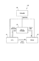
図1は、本実施形態による電子装置の構成例を概略的に示す図である。
図1に示す構成例において、本実施形態の電子装置100は、演算装置であるCPU(Central Processing Unit)10と、記憶装置であるDRAM20と、DRAM20のリセット制御を行うリセット制御回路30と、電源装置40とを備える。また、CPU10、DRAM20およびリセット制御回路30は、電源装置40から電源供給を受けている。なお、図1に示す構成例は、本実施形態における特徴的な構成のみが記載されている。実際には、外部装置とデータ交換を行うためのコントローラやインターフェイス、入力デバイス、表示制御装置などの種々の装置(モジュール、ユニット)が電子装置100に搭載される。
<Configuration of electronic device to which this embodiment is applied>
FIG. 1 is a diagram schematically showing a configuration example of an electronic device according to the present embodiment.
In the configuration example shown in FIG. 1, the
DRAM20は、例えば、DDR3等のリセット機能を有するRAM(Random Access Memory)であり、メモリ・コントローラ(DRAM制御部の一例)を介してデータの入出力が行われる。本実施形態では、CPU10がメモリ・コントローラの機能を兼ねる。
The
リセット制御回路30(リセット制御部の一例)は、DRAM20のリセット制御を行う。詳しくは後述するが、本実施形態では、DRAM20のリセット制御を、CPU10ではなく、専用の装置であるリセット制御回路30により行う。ここで、リセット制御回路30によるリセット制御は、予め設定された条件(リセット条件またはリセット解除条件)を満たすときにDRAM20へのリセット信号をLowレベルやHighレベルとし、次に別の条件(リセット解除条件またはリセット条件)を満たすまでその出力を維持するものである。一例として、電子装置100の電源投入時等、CPU10への電源供給が開始されるときには、DRAM20の初期化シーケンスを実行するために、リセット制御回路30は、DRAM20のリセット解除を行う。また、本実施形態では、リセット制御回路30は、予め設定されたDRAM20のリセット制御の他に、CPU10からのリセット操作依頼を受け付けると、DRAM20のリセット操作(リセットおよびリセット解除)を行う。
The reset control circuit 30 (an example of the reset control unit) performs reset control of the
CPU10は、各種の制御動作および演算処理を実行する。また、本実施形態のCPU10は、リセット制御回路30が行う予め設定されたリセット操作の他にCPU10からの制御に基づいてDRAM20のリセットを行う必要がある場合に、リセット制御回路30に対してDRAM20のリセット操作を依頼する。
The
本実施形態において、電子装置100は、いわゆる省電力モードの一つとして、CPU10の電源供給を停止するモードを有している。省電力モードでは、省電力モードに移行する際に電子装置100の動作状態についての情報がDRAM20等の記憶装置に保存され、その後に各装置への電源供給が停止される。そして、通常の動作モードに復帰する際、各装置は、記憶装置に保存されている動作状態の情報を取得して省電力モードへ移行する前の状態に復帰する。なお、DRAM20に情報を保存した場合、省電力モードにおいても、DRAM20に対しては、保存した情報を維持するために電源供給が継続される。一方、不揮発性の記憶装置に情報を保存した場合は、省電力モードにおいて、記憶装置に対する電源供給も停止することができる。
In the present embodiment, the
ここで、動作状態の情報がDRAM20に保存される場合、CPU10への電源供給が停止されると、CPU10からDRAM20へのリセット信号が0(OFF)になる。すると、DRAM20もリセット状態になってしまうので、DRAM20は、記憶内容を保持することができない。そこで、本実施形態の電子装置100は、CPU10への電源供給が停止されている間もDRAM20の記憶内容を保持させるため、外部回路(外部装置)であるリセット制御回路30を設け、CPU10ではなくリセット制御回路30によりDRAM20のリセット制御を行う。
Here, when the operating state information is stored in the
<DRAM20の仕様とレベリング>
また、本実施形態において、DRAM20は、マルチランク構成のDIMM(Dual Inline Memory Module)とする。複数のDRAMチップをプリント基板上に搭載したメモリモジュールをDIMMと呼び、メモリモジュールの動作ブロックの単位をランクと呼ぶ。マルチランクとは、1枚のDIMMに複数のランクが設けられていることを意味し、ランク2(ランクの数が2)、ランク4(ランクの数が4)等のDIMMが存在する。また、1枚のDIMMで1ランクが設けられたメモリモジュールをシングルランク・メモリ、2ランク使用するメモリモジュールをデュアルランク・メモリ等と呼ぶ。
<DRAM20 specifications and leveling>
Further, in the present embodiment, the
ところで、DDR3以降のDIMMは、フライバイ・トポロジと呼ばれる設計が行われている。そのため、メモリ・コントローラから送信された信号がDIMM上の各DRAM20に到達するのが同時ではなく、個々のDRAM20ごとに時間差が存在する。この時間差があることを前提としてデータの読み書きを正常に行うため、DIMMに対する電源投入時の初期化シーケンスにおいて、レベリングと呼ばれるメモリ・コントローラのタイミング調整が行われる。
By the way, DIMMs after DDR3 are designed as a fly-by topology. Therefore, the signals transmitted from the memory controller do not reach each
上述したマルチランク構成のDIMMでは、ランクごとに個別にレベリングを行うことが好適である。しかし、このレベリングの操作を簡易に行うため、一つのランクに対してレベリングを行って得られた調整結果を他のランクに対しても流用する手法がとられる場合がある。この場合、DIMMの初期化シーケンスにおいて、まず一つのランクのみを用いるモード(シングルランク・モード)にDIMMを設定してメモリ・コントローラのレベリングを行い、その後に複数ランクを用いるモード(マルチランク・モード)にDIMMの設定を変更して動作させるようにする。ここで、シングルランク・モードからマルチランク・モードに設定を変更するために、DIMM(DRAM20)をリセットすることが必要である。 In the DIMM having the multi-rank configuration described above, it is preferable to perform leveling individually for each rank. However, in order to simplify this leveling operation, a method may be adopted in which the adjustment result obtained by leveling one rank is also diverted to another rank. In this case, in the DIMM initialization sequence, first set the DIMM to a mode that uses only one rank (single rank mode), level the memory controller, and then use multiple ranks (multi-rank mode). ) To change the DIMM setting to operate. Here, it is necessary to reset the DIMM (DRAM20) in order to change the setting from the single rank mode to the multi rank mode.
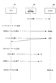
図2は、シングルランク・モードでレベリングを行った後にマルチランク・モードでDIMM(DRAM20)を使用するための初期化シーケンスの例を示すシーケンス図である。ここでは、レベリングを含む初期シーケンスの一般的な流れを説明するため、リセット制御回路30を用いず、CPU10によりリセット制御を行う場合の動作について説明する。
FIG. 2 is a sequence diagram showing an example of an initialization sequence for using a DIMM (DRAM20) in a multi-rank mode after leveling in a single-rank mode. Here, in order to explain the general flow of the initial sequence including leveling, the operation when the reset control is performed by the
図2に示す例において、CPU10およびDRAM20に対して電源装置40による電源供給が開始されると、まずCPU10からDRAM20へ送られるリセット信号がHighレベルとなり、DRAM20のリセット解除が行われる。そして、CPU10は、まずメモリ・コントローラとしての動作モードをシングルランク・モードに設定し、DRAM20の初期化シーケンスを実行し、レベリングを実行する。CPU10がDRAM20から応答を受けてレベリングが完了する。
In the example shown in FIG. 2, when the power supply to the
次に、CPU10は、メモリ・コントローラとしての動作モードをマルチランク・モードに再設定し、リセット操作を行う。すなわち、CPU10からDRAM20へ送られるリセット信号を一度Lowレベルにし(リセット)、再びHighレベルにする(リセット解除)。そして、CPU10は、マルチランク・モードでDRAM20の初期化シーケンスを実行する。この2回目の初期化シーケンスが終了すると、DRAM20は待機状態(スタンバイ)となり、CPU10は、DRAM20に対してマルチランク・モードでアクセス可能となる。
Next, the
<本実施形態におけるDRAM20の初期化シーケンス>
上述したように、本実施形態では、CPU10に代わってリセット制御回路30がDRAM20のリセット制御を行う。ここで、DRAM20の初期化シーケンスの実行時におけるリセット制御について考える。上述したように、本実施形態では、CPU10への電源供給が開始されると、リセット制御回路30がDRAM20へのリセット信号をHighレベルにしてリセットを解除し、CPU10が初期化シーケンスを開始する。
<Initialization sequence of
As described above, in the present embodiment, the
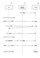
図3は、リセット制御回路30を含む構成において、シングルランク・モードでレベリングを行った後にマルチランク・モードでDIMM(DRAM20)を使用するための初期化シーケンスの例を示すシーケンス図である。本来、マルチランク・モードでDRAM20を使用する場合には、DRAM20の初期化シーケンスにおけるレベリングは、マルチランク・モードで行われる。この場合、DRAM20の初期化シーケンスの開始後にリセット操作が行われることはない。リセット操作を行うと、その度に再び初期化シーケンスを実行することとなるためである。そのため、図3に示す例では、リセット制御回路30は、最初にリセットを解除した後はDRAM20に対するリセット操作を行わない。
FIG. 3 is a sequence diagram showing an example of an initialization sequence for using a DIMM (DRAM20) in a multi-rank mode after leveling in a single rank mode in a configuration including a
図3に示すように、CPU10への電源供給が開始されると、リセット制御回路30は、DRAM20のリセットを解除する。そして、CPU10は、メモリ・コントローラとしての動作モードをシングルランク・モードに設定し、DRAM20の初期化シーケンスを実行し、レベリングを実行する。CPU10がDRAM20から応答を受けてレベリングが完了する。
As shown in FIG. 3, when the power supply to the
次に、CPU10は、メモリ・コントローラとしての動作モードをマルチランク・モードに再設定し、DRAM20のリセット操作を行おうとする。しかし、DRAM20のリセット制御はリセット制御回路30が行うように構成されている(CPU10は、DRAM20へのリセット信号線が接続されていない)ので、CPU10の制御によりDRAM20のリセット操作を行うことはできない。また、上述したように、リセット制御回路30は、このタイミングでDRAM20のリセット操作を行わない。そのため、この動作モードの再設定後のタイミングで、DRAM20はリセットされない。
Next, the
この後、CPU10は、DRAM20の初期化シーケンスを実行しようとするが、DRAM20は、リセットされていないために、CPU10からの再初期化コマンドに基づく初期化シーケンスが実行されない。したがって、CPU10は、この2回目の初期化シーケンスが終了した後、DRAM20に対してマルチランク・モードでアクセスしようとするが、DRAM20はシングルランク・モードのままとなり、CPU10からDRAM20へ正常にアクセスすることができなくなる。
After that, the
上記のように、DRAM20のリセット制御を外部回路であるリセット制御回路30で行う構成では、メモリ・コントローラにおいてシングルランク・モードでレベリングを行った後にマルチランク・モードでDIMM(DRAM20)を使用する場合、正常に初期化シーケンスを実行することができない。このような事態を回避するため、本実施形態では、CPU10は、DRAM20に対してリセット操作を行う必要がある場合に、リセット制御回路30に対してリセット操作を行うように依頼する。そして、リセット制御回路30が、CPU10からの依頼を受けてDRAM20のリセット操作を行う。
As described above, in the configuration in which the reset control of the
図4は、本実施形態によるDIMM(DRAM20)の初期化シーケンスを示すシーケンス図である。図4に示す動作において、CPU10が、シングルランク・モードでレベリングを実行し、DRAM20から応答を受けてレベリングが完了するまでの動作は、図3に示した動作と同様である。
FIG. 4 is a sequence diagram showing an initialization sequence of the DIMM (DRAM 20) according to the present embodiment. In the operation shown in FIG. 4, the operation until the
次に、CPU10は、リセット制御回路30に対してリセット依頼を行う。リセット制御回路30は、このCPU10からの依頼を受けて、DRAM20をリセットする(リセット信号をLowレベルにする)。そして、CPU10は、メモリ・コントローラとしての動作モードをマルチランク・モードに再設定し、リセット制御回路30に対してリセット解除依頼を行う。リセット制御回路30は、このCPU10からの依頼を受けて、DRAM20をリセット解除する(リセット信号をHighレベルにする)。
Next, the
この後、CPU10は、マルチランク・モードでDRAM20の初期化シーケンスを実行する。この2回目の初期化シーケンスが終了すると、DRAM20は待機状態(スタンバイ)となり、CPU10は、DRAM20に対してマルチランク・モードでアクセス可能となる。
After this, the
ここで、図4に示す動作では、CPU10は、マルチランク・モードに再設定する前に、リセット制御回路30にリセット依頼を行ってDRAM20をリセット(リセット信号がLowレベル)させ、マルチランク・モードへの再設定が終了した後に、リセット制御回路30にリセット解除依頼を行ってDRAM20をリセット解除(リセット信号がHighレベル)させた。このような手順をとったのは、DRAM20にとってCPU10が不定状態となって、DRAM20が予期せぬ状態となってしまうことを抑制するためである。すなわち、DRAM20をリセットする前にCPU10のマルチランク・モードへの再設定を行うと、DRAM20にとってCPU10が不定状態となる。すると、CPU10から出力される制御信号が、DRAM20において不定出力として認識される。そのため、DRAM20において、CPU10からの初期化コマンドに基づいて初期化シーケンスの再実行が行われなかったり、保存していたデータが消失したりする等の予期せぬ事態が発生する可能性があった。そこで、本実施形態では、図4に示したように、まずDRAM20をリセットしてからCPU10のマルチランク・モードへの再設定を行い、再設定が終了してCPU10がDRAM20にとって不定状態でなくなってからリセット解除することにより、DRAM20において予期せぬ事態が発生することを抑制している。
Here, in the operation shown in FIG. 4, the
以上説明したように、本実施形態は、CPU10がリセット制御回路30に対してリセット操作(リセットおよびリセット解除)を依頼し、リセット制御回路30がCPU10からの依頼に応じてDRAM20に対するリセット操作を実行する。このような構成としたことにより、本実施形態によれば、リセット制御回路30において予め設定された条件で行われるリセット操作以外にも、DRAM20のリセット操作を行う必要がある場合に、CPU10からリセット制御回路30へ依頼することにより、DRAM20のリセット操作を行うことが可能となる。
As described above, in the present embodiment, the
10…CPU、20…DRAM、30…リセット制御回路、40…電源装置、100…電子装置 10 ... CPU, 20 ... DRAM, 30 ... reset control circuit, 40 ... power supply device, 100 ... electronic device
Claims (4)
前記DRAMのリセット制御を行うリセット制御部と、
前記DRAMに対するアクセス制御を行うと共に、当該DRAMに対するリセット操作を前記リセット制御部に依頼するDRAM制御部と、を備え、
前記リセット制御部は、予め設定された条件に基づいて前記DRAMのリセット操作を行うと共に、前記DRAM制御部からの依頼に応じて当該DRAMのリセットおよびリセット解除を行い、
前記DRAM制御部は、電源供給を開始された際の動作として、
シングルランク・モードで前記DRAMに対する初期化シーケンスを実行して当該DRAMに対するアクセスのタイミング調整を行い、
次に、前記リセット制御部に当該DRAMのリセットを依頼し、当該シングルランク・モードからマルチランク・モードに変更した後に、当該リセット制御部に当該DRAMのリセット解除を依頼し、
当該マルチランク・モードで当該DRAMに対する初期化シーケンスを実行することを特徴とする、電子装置。 Resettable DRAM (Dynamic Random Access Memory) and
A reset control unit that controls the reset of the DRAM,
It is provided with a DRAM control unit that controls access to the DRAM and requests the reset control unit to perform a reset operation on the DRAM.
The reset control unit performs a reset operation of the DRAM based on preset conditions, and also resets and releases the DRAM in response to a request from the DRAM control unit.
The DRAM control unit operates as an operation when the power supply is started.
The initialization sequence for the DRAM is executed in the single rank mode to adjust the timing of access to the DRAM.
Next, the reset control unit is requested to reset the DRAM, and after changing from the single rank mode to the multi-rank mode, the reset control unit is requested to release the reset of the DRAM.
An electronic device characterized by performing an initialization sequence for the DRAM in the multi-rank mode.
前記DRAM制御部は、前記リセット制御部による前記DRAMのリセット解除が行われた後に、当該DRAMに対する初期化シーケンスを実行することを特徴とする、請求項1に記載の電子装置。 When the power supply to the DRAM control unit is started, the reset control unit resets and releases the DRAM.
The electronic device according to claim 1, wherein the DRAM control unit executes an initialization sequence for the DRAM after the reset control unit has released the reset of the DRAM.
電源供給を開始されると、シングルランク・モードで動作して、前記DRAMに対するアクセスのタイミング調整を行い、
前記DRAMのリセット制御を行う外部装置に当該DRAMをリセットさせ、リセット解除後に、マルチランク・モードで前記DRAMに対する初期化シーケンスを実行することを特徴とする、装置。 A device that controls access to a resettable DRAM (Dynamic Random Access Memory).
When the power supply is started, it operates in the single rank mode, adjusts the timing of access to the DRAM, and adjusts the timing of access to the DRAM.
An apparatus characterized in that an external device that performs reset control of the DRAM resets the DRAM, and after the reset is released, an initialization sequence for the DRAM is executed in a multi-rank mode.
シングルランク・モードで前記DRAMに対する初期化シーケンスを実行して当該DRAMに対するアクセスのタイミング調整を行い、
前記DRAMのリセット制御を行う外部装置に、当該DRAMのリセットを依頼し、
前記シングルランク・モードからマルチランク・モードに変更し、
前記外部装置に、前記DRAMのリセット解除を依頼し、
前記マルチランク・モードで前記DRAMに対する初期化シーケンスを実行することを特徴とする、DRAMの初期化方法。 It is a method of initializing the DRAM by a DRAM control unit that controls access to a resettable DRAM (Dynamic Random Access Memory).
The initialization sequence for the DRAM is executed in the single rank mode to adjust the timing of access to the DRAM.
A request is made to an external device that controls the reset of the DRAM to reset the DRAM.
Change from the single rank mode to the multi rank mode
Request the external device to reset and release the DRAM,
A method for initializing a DRAM, which comprises executing an initialization sequence for the DRAM in the multi-rank mode.
Priority Applications (1)
| Application Number | Priority Date | Filing Date | Title |
|---|---|---|---|
| JP2016187345A JP6957848B2 (en) | 2016-09-26 | 2016-09-26 | How to initialize electronic devices and DRAM |
Applications Claiming Priority (1)
| Application Number | Priority Date | Filing Date | Title |
|---|---|---|---|
| JP2016187345A JP6957848B2 (en) | 2016-09-26 | 2016-09-26 | How to initialize electronic devices and DRAM |
Publications (2)
| Publication Number | Publication Date |
|---|---|
| JP2018055192A JP2018055192A (en) | 2018-04-05 |
| JP6957848B2 true JP6957848B2 (en) | 2021-11-02 |
Family
ID=61834151
Family Applications (1)
| Application Number | Title | Priority Date | Filing Date |
|---|---|---|---|
| JP2016187345A Active JP6957848B2 (en) | 2016-09-26 | 2016-09-26 | How to initialize electronic devices and DRAM |
Country Status (1)
| Country | Link |
|---|---|
| JP (1) | JP6957848B2 (en) |
Family Cites Families (4)
| Publication number | Priority date | Publication date | Assignee | Title |
|---|---|---|---|---|
| JP4620504B2 (en) * | 2005-03-10 | 2011-01-26 | 富士通セミコンダクター株式会社 | Semiconductor memory and system device |
| JP5096131B2 (en) * | 2007-12-27 | 2012-12-12 | ルネサスエレクトロニクス株式会社 | Semiconductor memory device |
| JP2012059184A (en) * | 2010-09-13 | 2012-03-22 | Nec Computertechno Ltd | Memory controller, memory system with the same and control method of memory device |
| JP2012068873A (en) * | 2010-09-22 | 2012-04-05 | Toshiba Corp | Memory system and dram controller |
-
2016
- 2016-09-26 JP JP2016187345A patent/JP6957848B2/en active Active
Also Published As
| Publication number | Publication date |
|---|---|
| JP2018055192A (en) | 2018-04-05 |
Similar Documents
| Publication | Publication Date | Title |
|---|---|---|
| US9645829B2 (en) | Techniques to communicate with a controller for a non-volatile dual in-line memory module | |
| KR102693794B1 (en) | Memory module capable of improving row hammering and operation method thereof | |
| US9990246B2 (en) | Memory system | |
| US8909957B2 (en) | Dynamic voltage adjustment to computer system memory | |
| KR101997316B1 (en) | Control apparatus, control method of control apparatus, and storage medium | |
| CN102906717A (en) | Initializing a memory subsystem of a management controller | |
| US20180203816A1 (en) | System including hot plug module and memory module | |
| CN108351850B (en) | Techniques for simultaneous access to non-volatile and volatile memory in memory devices | |
| TW201636859A (en) | Memory system, memory module and operation method thereof | |
| JP6447167B2 (en) | Semiconductor device, log acquisition method, and electronic apparatus | |
| US12399846B2 (en) | Physical adjustment to system memory with chipset attached memory | |
| US8938600B2 (en) | Memory system, memory control method, and recording medium storing memory control program | |
| US20160103615A1 (en) | Apparatuses and methods including selectively providing a single or separate chip select signals | |
| KR102822697B1 (en) | Semiconductor memory device, electronic device and method for setting the same | |
| JP2009282721A (en) | Memory controller, memory control system, and method of controlling amount of delay in memory | |
| EP3701354B1 (en) | Memory module with programmable command buffer | |
| JP6957848B2 (en) | How to initialize electronic devices and DRAM | |
| WO2022216344A1 (en) | Enhanced d3-c0ld and faster recovery | |
| JP2018128845A (en) | Multiprocessor system | |
| US9396788B1 (en) | Information processing apparatus and information processing method | |
| JP6700739B2 (en) | Controller and control method | |
| JP4501868B2 (en) | Memory system control method | |
| TWI515569B (en) | Accessing system and memory device | |
| KR20210082289A (en) | Memory system, memory module and method for thermal throttling | |
| KR101477809B1 (en) | Computer system controlling memory module and control method thereof |
Legal Events
| Date | Code | Title | Description |
|---|---|---|---|
| A621 | Written request for application examination |
Free format text: JAPANESE INTERMEDIATE CODE: A621 Effective date: 20190830 |
|
| A977 | Report on retrieval |
Free format text: JAPANESE INTERMEDIATE CODE: A971007 Effective date: 20200709 |
|
| A131 | Notification of reasons for refusal |
Free format text: JAPANESE INTERMEDIATE CODE: A131 Effective date: 20200825 |
|
| A521 | Request for written amendment filed |
Free format text: JAPANESE INTERMEDIATE CODE: A523 Effective date: 20201021 |
|
| A131 | Notification of reasons for refusal |
Free format text: JAPANESE INTERMEDIATE CODE: A131 Effective date: 20210330 |
|
| A521 | Request for written amendment filed |
Free format text: JAPANESE INTERMEDIATE CODE: A523 Effective date: 20210526 |
|
| TRDD | Decision of grant or rejection written | ||
| A01 | Written decision to grant a patent or to grant a registration (utility model) |
Free format text: JAPANESE INTERMEDIATE CODE: A01 Effective date: 20210907 |
|
| A61 | First payment of annual fees (during grant procedure) |
Free format text: JAPANESE INTERMEDIATE CODE: A61 Effective date: 20210920 |
|
| R150 | Certificate of patent or registration of utility model |
Ref document number: 6957848 Country of ref document: JP Free format text: JAPANESE INTERMEDIATE CODE: R150 |