JP6955343B2 - Infrared cut filter and imaging optical system - Google Patents
Infrared cut filter and imaging optical system Download PDFInfo
- Publication number
- JP6955343B2 JP6955343B2 JP2017025363A JP2017025363A JP6955343B2 JP 6955343 B2 JP6955343 B2 JP 6955343B2 JP 2017025363 A JP2017025363 A JP 2017025363A JP 2017025363 A JP2017025363 A JP 2017025363A JP 6955343 B2 JP6955343 B2 JP 6955343B2
- Authority
- JP
- Japan
- Prior art keywords
- wavelength
- film
- transmittance
- cut filter
- spectral transmittance
- Prior art date
- Legal status (The legal status is an assumption and is not a legal conclusion. Google has not performed a legal analysis and makes no representation as to the accuracy of the status listed.)
- Active
Links
Images


Description
本発明は、赤外線カットフィルタ及び撮像光学系に関する。 The present invention relates to an infrared cut filter and an imaging optical system.
デジタルカメラなどの撮像装置において、撮像素子として、CCD(Charge Coupled Device)やCMOS(Complementary Metal Oxide Semiconductor)などのSi(シリコン)を用いた2次元画像センサが使用されている。Siを用いた撮像素子は、赤外線域の波長の光に対する受光感度を有し、人間の視感度とは異なる波長特性を有する。このため、撮像装置において、得られる画像が人間の認識した画像に近づくように、撮像素子の前方に赤外線域の波長の入射光を遮蔽するフィルタ(赤外線カットフィルタ)が通常配置されている。 In an image pickup device such as a digital camera, a two-dimensional image sensor using Si (silicon) such as a CCD (Charge Coupled Device) or a CMOS (Complementary Metal Oxide Semiconductor) is used as an image pickup element. The image sensor using Si has a light receiving sensitivity to light having a wavelength in the infrared region, and has a wavelength characteristic different from that of human visual sensitivity. Therefore, in the image pickup device, a filter (infrared cut filter) that shields incident light having a wavelength in the infrared region is usually arranged in front of the image pickup device so that the obtained image approaches an image recognized by a human being.
例えば、赤外線を反射する能力を有する膜が透明基板に積層された赤外線カットフィルタが知られている。このような赤外線カットフィルタは、赤外線を反射する能力を有する膜の材料及び厚みを調整することによって、赤外線を反射するのみならず紫外線も反射する分光特性など様々な分光特性を有する。しかし、このような赤外線カットフィルタは、赤外線カットフィルタに大きな入射角で光が入射するときに透過率スペクトルを短波長側にシフトさせる。このため、このような赤外線カットフィルタを使用して得られた画像の中心部及び周辺部には互いに異なる色味が生じることがある。そこで、透過率スペクトルの入射角依存性を小さくするために様々な提案がなされている。 For example, an infrared cut filter in which a film having an ability to reflect infrared rays is laminated on a transparent substrate is known. Such an infrared cut filter has various spectral characteristics such as spectral characteristics that not only reflect infrared rays but also reflect ultraviolet rays by adjusting the material and thickness of the film having the ability to reflect infrared rays. However, such an infrared cut filter shifts the transmittance spectrum to the short wavelength side when light is incident on the infrared cut filter at a large incident angle. Therefore, different colors may occur in the central portion and the peripheral portion of the image obtained by using such an infrared cut filter. Therefore, various proposals have been made to reduce the incident angle dependence of the transmittance spectrum.
例えば、特許文献1には、所定の吸収剤を含有した透明樹脂基板と、近赤外線反射膜とを有する近赤外線カットフィルタが記載されている。その吸収剤は、波長600〜800nmに吸収極大があり、かつ、波長430〜800nmの波長領域において、透過率が70%となる吸収極大以下で最も長い波長(Aa)と、波長580nm以上の波長領域において、透過率が30%となる最も短い波長(Ab)との差の絶対値が75nm未満であるという特性を有している。また、その近赤外線反射膜は、アルミ蒸着膜、貴金属薄膜、酸化インジウムを主成分とし酸化錫を少量含有させた金属酸化物微粒子を分散させた樹脂膜、及び高屈折率材料層と低屈折率材料層とを交互に積層した誘電体多層膜などの膜である。
For example,
特許文献1に記載の近赤外線カットフィルタは、YaとYbとの差の絶対値が15nm未満であるという特性を有する。Yaは、波長560〜800nmの範囲において、近赤外線カットフィルタの垂直方向から測定した場合の光の透過率が50%となる波長の値である。Ybは、波長560〜800nmの範囲において、近赤外線カットフィルタの垂直方向に対して30°の角度から測定した場合の光の透過率が50%となる波長の値である。
The near-infrared cut filter described in
上記のように、特許文献1に記載の近赤外線カットフィルタでは、YaとYbとの差の絶対値が15nm未満であるものの、特許文献1に記載の近赤外線カットフィルタに30°を超える入射角で光が入射する場合の光の透過率に関する特性は具体的に検討されていない。近年の撮像レンズの高画角化により、30°を超える入射角で赤外線カットフィルタに光が入射する場合でも、より高いレベルの画質が要求されるようになってきている。このため、より大きな入射角(例えば、40°)で被写体からの光が赤外線カットフィルタに入射する場合にも、特定の波長範囲(例えば、600〜700nm)において透過率の変化を抑制できる技術が望まれている。
As described above, in the near-infrared cut filter described in
このような事情に鑑み、本発明は、近赤外線反射膜を備えつつ、0°〜40°の角度で光の入射角が変化しても、特定の範囲の波長(例えば、600〜700nm)における透過率スペクトルの変化が十分に小さい赤外線カットフィルタを提供する。 In view of these circumstances, the present invention provides a near-infrared reflective film and has a wavelength in a specific range (for example, 600 to 700 nm) even if the incident angle of light changes at an angle of 0 ° to 40 °. Provided is an infrared cut filter in which the change in the transmittance spectrum is sufficiently small.
本発明は、
近赤外線反射膜と、
前記近赤外線反射膜と平行に延びている吸収膜と、を備え、
前記近赤外線反射膜及び前記吸収膜は、当該近赤外線反射膜及び波長400〜1100nmにおいて90%以上の平均分光透過率を有する透明誘電体基板のみによって形成された第一積層体と、当該吸収膜及び前記透明誘電体基板のみによって形成された第二積層体とに、下記(A)〜(E)の特性を付与する、
赤外線カットフィルタを提供する。
(A)前記第一積層体に垂直に入射する光の分光透過率は、波長600〜800nmの範囲における当該分光透過率が70%であるときの波長λH R(0°,70%)が700nm以上であり、かつ、波長600〜800nmの範囲における当該分光透過率が20%であるときの波長λH R(0°,20%)が770nm以下であるとともに前記波長λH R(0°,70%)よりも大きいように、前記波長λH R(0°,70%)〜前記波長λH R(0°,20%)の範囲で単調に減少し、
(B)前記第一積層体に40°の入射角で入射する光の分光透過率は、波長600〜800nmの範囲における当該分光透過率が70%であるときの波長λH R(40°,70%)が650nm以上であり、かつ、波長600〜800nmの範囲における当該分光透過率が20%であるときの波長λH R(40°,20%)が720nm以下であるとともに前記波長λH R(40°,70%)よりも大きいように、前記波長λH R(40°,70%)〜前記波長λH R(40°,20%)の範囲で単調に減少し、
(C)前記第二積層体に40°の入射角で入射する光の分光透過率は、波長600〜800nmの範囲において、前記波長λH R(40°,20%)より小さい波長λH A(40°,20%)で、20%であり、λHR(40°,20%)
(D)前記第二積層体に垂直に入射する光の分光透過率は前記波長λH R(0°,20%)において15%以下であり、
(E)前記第一積層体に垂直に入射する光の分光透過率及び前記第一積層体に40°の入射角で入射する光の分光透過率の450〜600nmの波長範囲における平均値は、75%以上であり、かつ、前記第二積層体に垂直に入射する光の分光透過率及び前記第二積層体に40°の入射角で入射する光の分光透過率の450〜600nmの波長範囲における平均値は、75%以上である。
The present invention
Near-infrared reflective film and
An absorbent film extending in parallel with the near-infrared reflective film is provided.
The near-infrared reflecting film and the absorbing film are a first laminate formed only of the near-infrared reflecting film and a transparent dielectric substrate having an average spectral transmittance of 90% or more at a wavelength of 400 to 1100 nm, and the absorbing film. And the second laminate formed only by the transparent dielectric substrate, the following characteristics (A) to (E) are imparted.
To provide an infrared cut filter.
(A) The spectral transmission of light vertically incident on the first laminated body has a wavelength λ H R (0 °, 70%) when the spectral transmission is 70% in the wavelength range of 600 to 800 nm. The wavelength λ H R (0 °, 20%) is 770 nm or less and the wavelength λ H R (0 °) when the spectral transmittance is 20% in the wavelength range of 600 to 800 nm and 700 nm or more. , 70%), monotonically decreasing in the range of the wavelength λ H R (0 °, 70%) to the wavelength λ H R (0 °, 20%).
(B) The spectral transmission of light incident on the first laminated body at an incident angle of 40 ° is the wavelength λ H R (40 °, 40 °, when the spectral transmission is 70% in the wavelength range of 600 to 800 nm. 70%) is 650 nm or more, and the wavelength λ H R (40 °, 20%) when the spectral transmittance in the wavelength range of 600 to 800 nm is 20% is 720 nm or less, and the wavelength λ H R (40 °, 70%) as greater than, the wavelength λ H R (40 °, 70 %) ~ the wavelength λ H R (40 °, 20 %) monotonically decreases in a range of,
(C) the spectral transmittance of the incident light at an incident angle of the
(D) The spectral transmittance of the light vertically incident on the second laminated body is 15% or less at the wavelength λ H R (0 °, 20%).
(E) The average value of the spectral transmittance of the light vertically incident on the first laminated body and the spectral transmittance of the light incident on the first laminated body at an incident angle of 40 ° in the wavelength range of 450 to 600 nm is A wavelength range of 450 to 600 nm of the spectral transmittance of light that is 75% or more and is vertically incident on the second laminated body and the spectral transmittance of light that is incident on the second laminated body at an incident angle of 40 °. The average value in is 75% or more.
また、本発明は、上記の赤外線カットフィルタを備えた、撮像光学系を提供する。 The present invention also provides an imaging optical system provided with the above-mentioned infrared cut filter.
上記の赤外線カットフィルタは、近赤外線反射膜を備えつつ、0°〜40°の角度で光の入射角が変化しても、特定の範囲の波長(例えば、600〜700nm)における透過率スペクトルの変化が十分に小さい。 The above-mentioned infrared cut filter is provided with a near-infrared reflective film, and has a transmittance spectrum in a specific range of wavelengths (for example, 600 to 700 nm) even if the incident angle of light changes at an angle of 0 ° to 40 °. The change is small enough.
以下、本発明の実施形態について図面を参照しながら説明する。なお、以下の説明は、本発明の一例に関するものであり、本発明はこれらに限定されるものではない。 Hereinafter, embodiments of the present invention will be described with reference to the drawings. The following description relates to an example of the present invention, and the present invention is not limited thereto.
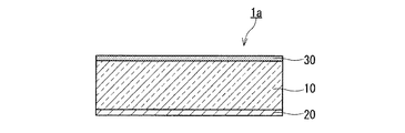
図1に示す通り、赤外線カットフィルタ1aは、近赤外線反射膜20と、吸収膜30とを備えている。吸収膜30は、近赤外線反射膜20と平行に延びている。近赤外線反射膜20及び吸収膜30は、近赤外線反射膜20及び波長400〜1100nmにおいて90%以上の平均分光透過率を有する透明誘電体基板のみによって形成された第一積層体と、吸収膜30及び波長400〜1100nmにおいて90%以上の平均分光透過率を有する透明誘電体基板のみによって形成された第二積層体とに、下記(A)〜(E)の特性を付与する。
(A)第一積層体に垂直に入射する光の分光透過率は、波長600〜800nmの範囲における当該分光透過率が70%であるときの波長λH R(0°,70%)が700nm以上であり、かつ、波長600〜800nmの範囲における当該分光透過率が20%であるときの波長λH R(0°,20%)が770nm以下であるとともに波長λH R(0°,70%)よりも大きいように、波長λH R(0°,70%)〜波長λH R(0°,20%)の範囲
で単調に減少する。
(B)第一積層体に40°の入射角で入射する光の分光透過率は、波長600〜800nmの範囲における当該分光透過率が70%であるときの波長λH R(40°,70%)が650nm以上であり、かつ、波長600〜800nmの範囲における当該分光透過率が20%であるときの波長λH R(40°,20%)が720nm以下であるとともに波長λH R(40°,70%)よりも大きいように、波長λH R(40°,70%)〜波長λH R(40°,20%)の範囲で単調に減少する。
(C)第二積層体に40°の入射角で入射する光の分光透過率は、波長600〜800nmの範囲において、波長λH R(40°,20%)より小さい波長λH A(40°,20%)で、20%である。
(D)第二積層体に垂直に入射する光の分光透過率は波長λH R(0°,20%)において15%以下であり、
(E)第一積層体に垂直に入射する光の分光透過率及び第一積層体に40°の入射角で入射する光の分光透過率の450〜600nmの波長範囲における平均値は、75%以上であり、かつ、第二積層体に垂直に入射する光の分光透過率及び第二積層体に40°の入射角で入射する光の分光透過率の450〜600nmの波長範囲における平均値は、75%以上である。
As shown in FIG. 1, the
(A) The spectral transmittance of light vertically incident on the first laminated body is 700 nm at a wavelength λ H R (0 °, 70%) when the spectral transmittance is 70% in the wavelength range of 600 to 800 nm. The wavelength λ H R (0 °, 20%) is 770 nm or less and the wavelength λ H R (0 °, 70) when the spectral transmittance in the wavelength range of 600 to 800 nm is 20%. %), It decreases monotonically in the range of wavelength λ H R (0 °, 70%) to wavelength λ H R (0 °, 20%).
(B) The spectral transmission of light incident on the first laminated body at an incident angle of 40 ° is the wavelength λ H R (40 °, 70) when the spectral transmission is 70% in the wavelength range of 600 to 800 nm. %) Is 650 nm or more, and the wavelength λ H R (40 °, 20%) is 720 nm or less and the wavelength λ H R (%) when the spectral transmittance in the wavelength range of 600 to 800 nm is 20%. It decreases monotonically in the range of wavelength λ H R (40 °, 70%) to wavelength λ H R (40 °, 20%) so as to be larger than 40 °, 70%).
(C) the spectral transmittance of light at an incident angle of 40 ° to the second laminate, in a range of
(D) the spectral transmittance of the light perpendicularly entering the second stack wavelength λ H R (0 °, 20 %) is 15% or less in,
(E) The average value of the spectral transmittance of light vertically incident on the first laminated body and the spectral transmittance of light incident on the first laminated body at an incident angle of 40 ° in the wavelength range of 450 to 600 nm is 75%. The average values of the spectral transmittance of the light vertically incident on the second laminated body and the spectral transmittance of the light incident on the second laminated body at an incident angle of 40 ° in the wavelength range of 450 to 600 nm are as described above. , 75% or more.
第一積層体は、上記(A)及び(B)の特性を有するので、第一積層体に0°〜40°の入射角で入射する光に対する分光透過率は、波長650nm〜770nmの範囲において急峻に低下する。第一積層体に垂直に入射する光の分光透過率及び第一積層体に40°の入射角で入射する光の分光透過率は、例えば、波長770〜1100nmの範囲において、平均値で1%以下である。これにより、赤外線カットフィルタ1aは、近赤外線を効果的に反射できる。波長λH R(0°,70%)から波長λH R(40°,70%)を差し引いた差ΔλH R(70%)(=λH R(0°,70%)−λH R(40°,70%))は、例えば、40〜60nmである。また、波長λH R(0°,20%)から波長λH R(40°,20%)を差し引いた差ΔλH R(20%)(=λH R(0°,20%)−λH R(40°,20%))は、例えば、40〜55nmである。このように、第一積層体に入射する光の入射角が0°から40°に変化すると、第一積層体に入射する光の透過率スペクトルが短波長側にシフトする。
Since the first laminated body has the above-mentioned characteristics (A) and (B), the spectral transmittance for light incident on the first laminated body at an incident angle of 0 ° to 40 ° is in the wavelength range of 650 nm to 770 nm. It drops sharply. The spectral transmittance of light vertically incident on the first laminated body and the spectral transmittance of light incident on the first laminated body at an incident angle of 40 ° are, for example, 1% on average in the wavelength range of 770 to 1100 nm. It is as follows. As a result, the
第二積層体が上記(C)及び(D)の特性を有することにより、赤外線カットフィルタ1aに0°〜40°の角度で光の入射角が変化しても、特定の範囲の波長600〜700nmにおける透過率スペクトルの変化が小さくなる。例えば、さらに、第二積層体に40°の入射角で入射する光の分光透過率は波長λH R(40°,20%)において15%以下である。例えば、赤外線カットフィルタ1aに垂直に入射する光の分光透過率が波長600〜700nmの範囲で50%である波長と赤外線カットフィルタに40°の入射角で入射する光の分光透過率が波長600〜700nmの範囲で50%である波長との差の絶対値|ΔλH(50%)|が10nm以下である。なお、第二積層体に入射する光の分光透過率は、第二積層体に入射する光の入射角が0°〜40°の範囲ではほとんど変化しない。換言すると、第二積層体に垂直に入射する光の分光透過率と第二積層体に40°の入射角で入射する光の分光透過率とは実質的に同一である。
Since the second laminated body has the above-mentioned characteristics (C) and (D), even if the incident angle of light changes at an angle of 0 ° to 40 ° to the
第一積層体及び第二積層体が上記(E)の特性を有することにより、赤外線カットフィルタ1aは、波長450〜600nmの範囲で高い分光透過率を有する。第一積層体に垂直に入射する光の分光透過率及び第一積層体に40°の入射角で入射する光の分光透過率の450〜600nmの波長範囲における平均値は、望ましくは85%以上であり、より望ましくは90%以上である。第二積層体に垂直に入射する光の分光透過率及び第二積層体に40°の入射角で入射する光の分光透過率の450〜600nmの波長範囲における平均値は、望ましくは85%以上であり、より望ましくは90%以上である。
Since the first laminated body and the second laminated body have the above-mentioned characteristics (E), the
図1に示す通り、赤外線カットフィルタ1aは、例えば、透明誘電体基板10をさらに備えている。この場合、近赤外線反射膜20及び吸収膜30は、透明誘電体基板10の主面に平行に延びている。透明誘電体基板10は、場合によっては省略可能である。
As shown in FIG. 1, the
図1に示す通り、赤外線カットフィルタ1aにおいて、近赤外線反射膜20は透明誘電体基板10の一方の主面に接触している。透明誘電体基板10の材料は、例えば、高温高湿等の環境に対する耐性及び優れた耐薬品性を有することが望ましい。特に、近赤外線反射膜20が形成される工程において透明誘電体基板10が高温環境に置かれる場合には、透明誘電体基板10はそのような高温環境に十分な耐性を有する必要がある。透明誘電体基板10の材料は、例えば、ホウケイ酸ガラスなどのガラス、ポリオレフィン系樹脂、アクリル系樹脂、ポリエステル系樹脂、アラミド系樹脂、イミド系樹脂、アミド系樹脂、ポリカーボネート(PC)、アセチルセルロース、ポリ塩化ビニル、ポリビニルアセタール(PVA)、又はポリビニルブチラールである。透明誘電体基板10の厚みは、例えば50〜400μmである。
As shown in FIG. 1, in the
近赤外線反射膜20は、可視光域の光に対して高い透過率を示し、かつ、赤外線域の光に対して低い透過率を示す透過率スペクトルを有する。換言すると、近赤外線反射膜20の透過率スペクトルは可視光域に透過帯域を有するとともに赤外線域に赤外線反射帯域を有し、透過帯域と赤外線反射帯域との間に遷移帯域が存在する。
The near-infrared
近赤外線反射膜20は、例えば、波長400nm以下の光に対する低い透過率を有していてもよい。例えば、第一積層体に垂直に入射する光の波長350〜380nmの範囲における分光透過率の平均値は20%以下である。この場合、近赤外線反射膜20の透過率スペクトルの可視光域、赤外線域、及び紫外線域には、それぞれ、透過帯域、赤外線反射帯域、及び紫外線反射帯域が存在する。加えて、透過帯域と赤外線反射帯域との間には波長の増加に対し透過率が急速に低下する遷移帯域が存在し、紫外線反射帯域と透過帯域との間には波長の増加に対し透過率が急速に増加する遷移帯域が存在する。この場合、例えば、吸収膜30に含まれる成分に紫外線が照射されることを抑制できる。
The near-infrared
近赤外線反射膜20は、例えば、透明誘電体基板10の一方の主面上に無機材料又は有機材料の層を積層することにより形成されている。近赤外線反射膜20は、1種類の材料が透明誘電体基板10の一方の主面に積層されて形成されていてもよいし、2種類以上の材料が透明誘電体基板10の一方の主面から代わる代わる積層されて形成されていてもよい。近赤外線反射膜20は、例えば、SiO2、TiO2、Ta2O5、及びMgF等の材料から選ばれる1種の材料が透明誘電体基板10の一方の主面に積層されて形成されていてもよい。また、近赤外線反射膜20は、例えば、SiO2、TiO2、Ta2O5、及びMgF等の材料から選択された屈折率の異なる2種以上の材料が透明誘電体基板10の一方の主面から代わる代わる積層されて形成されていてもよい。この場合、近赤外線反射膜20の設計の自由度が高く、近赤外線反射膜20の特性を細かく調整しやすい。このため、近赤外線反射膜20が所望の光学特性を容易に発揮できる。また、近赤外線反射膜20は、例えば二組以上の反射膜に分割されて形成されていてもよい。この場合、二組以上の反射膜は各々異なる波長域の光を反射していてもよいし、一部の波長域の光は複数の反射膜で反射していてもよい。例えば、第一反射膜が近赤外波長域内の例えば波長750〜1100nmの範囲内の比較的短波長側の光を主として反射し、第二反射膜が上記波長範囲内の比較的長波長側の光を主として反射するように設計、作製したうえで、第一反射膜と第二反射膜の反射特性とを合成することによって、波長750〜1100nmの範囲内の波長域の光を反射でき、場合によっては400nm以下の波長域の光も反射できるように近赤外線反射膜20を設計及び作製できる。または、第一反射膜及び第二反射膜のいずれかの反射膜のみの特性だけでは、例えば反射膜で遮蔽すべき波長750〜1100nmの範囲内において透過率がベースラインより大きくなるような範囲が現れて、漏れ光が生じることがある。これを低減又は防止するために反射特性の異なる反射膜を組み合わせてもよい。近赤外線反射膜20の厚みは、例えば4〜10μmである。
The near-infrared
近赤外線反射膜20は、例えば、(i)蒸着法、スパッタリング法、イオンプレーティング法、及びイオンアシスト蒸着(IAD)法等の物理的な方法、(ii)化学気相蒸着(CVD)法等の化学的な方法、又は(iii)ゾルゲル法等の湿式法によって形成される。
The near-infrared
近赤外線反射膜20及び吸収膜30は、第一積層体と、第二積層体とに、下記(F)〜(I)の特性をさらに付与する。
(F)第一積層体に垂直に入射する光の分光透過率は、波長350〜450nmの範囲において、当該分光透過率が20%であるときの波長λL R(0°,20%)が390nm以上であるとともに、当該分光透過率が70%であるときの波長λL R(0°,70%)よりも小さいように、波長λL R(0°,20%)〜波長λL R(0°,70%)の範囲で単調に増加する。
(G)第一積層体に40°の入射角で入射する光の分光透過率は、波長350〜450nmの範囲において、当該分光透過率が20%であるときの波長λL R(40°,20%)が370nm以上であるとともに、当該分光透過率が70%であるときの波長λL R(40°,70%)よりも小さいように、波長λL R(40°,20%)〜波長λL R(40°,70%)の範囲で単調に増加する。
(H)第二積層体に40°の入射角で入射する光の分光透過率は、波長350〜450nmの範囲において、当該分光透過率が20%であるときの波長λL A(40°,20%)が370nm以上であるとともに、当該分光透過率が50%であるときの波長λL A(40°,50%)よりも小さいように、波長λL A(40°,20%)〜波長λL A(40°,50%)の範囲で単調に増加する。
(I)波長350〜450nmの範囲において、第一積層体に垂直に入射する光の分光透過率が50%であるときの波長λL R(0°,50%)における、第二積層体に40°の入射角で入射する光の分光透過率が60%以下である。
The near-infrared
(F) The spectral transmittance of light vertically incident on the first laminated body has a wavelength λ L R (0 °, 20%) when the spectral transmittance is 20% in the wavelength range of 350 to 450 nm. Wavelength λ L R (0 °, 20%) to wavelength λ L R so that it is 390 nm or more and smaller than the wavelength λ L R (0 °, 70%) when the spectral transmittance is 70%. It increases monotonically in the range of (0 °, 70%).
(G) The spectral transmittance of light incident on the first laminated body at an incident angle of 40 ° is the wavelength λ L R (40 °, 40 °, when the spectral transmittance is 20% in the wavelength range of 350 to 450 nm. Wavelength λ L R (40 °, 20%) ~ so that 20%) is 370 nm or more and smaller than the wavelength λ L R (40 °, 70%) when the spectral transmittance is 70%. It increases monotonically in the wavelength range λ L R (40 °, 70%).
(H) the spectral transmittance of light at an incident angle of 40 ° to the second laminate, in a range of
(I) In the wavelength range of 350 to 450 nm, in the second laminate at the wavelength λ L R (0 °, 50%) when the spectral transmittance of the light vertically incident on the first laminate is 50%. The spectral transmittance of light incident at an incident angle of 40 ° is 60% or less.
第二積層体が上記(H)及び(I)の特性を有することにより、赤外線カットフィルタ1aに0°〜40°の角度で光の入射角が変化しても、特定の範囲の波長350〜450nm、特に波長400nm付近における透過率スペクトルの変化が小さい。
Since the second laminated body has the above-mentioned characteristics (H) and (I), even if the incident angle of light changes at an angle of 0 ° to 40 ° to the
第一積層体及び第二積層体が(F)〜(I)の特性を有する場合、例えば、赤外線カットフィルタ1aに垂直に入射する光の分光透過率が波長350〜450nmの範囲で50%である波長と、赤外線カットフィルタ1aに40°の入射角で入射する光の分光透過率が波長350〜450nmの範囲で50%である波長との差の絶対値|ΔλL(50%)|が10nm以下である。
When the first laminate and the second laminate have the characteristics (F) to (I), for example, the spectral transmittance of light vertically incident on the
近赤外線反射膜20は、第一積層体に、下記(J)の特性を付与してもよい。
(J)第一積層体に40°の入射角で入射する光の分光透過率が、波長400〜450nmの範囲でベースラインとの差が10ポイント以上である極小値を有し、かつ、当該極小値に対応する半値幅が10nm以上であり、当該半値幅をΔλCと定義したときに(400−ΔλC/2)〜(450−ΔλC/2)nmの範囲に極大値が存在するスペクトルを有する。
The near-infrared
(J) The spectral transmittance of light incident on the first laminated body at an incident angle of 40 ° has a minimum value of 10 points or more from the baseline in the wavelength range of 400 to 450 nm, and is said to be relevant. half-width corresponding to the minimum value is not less 10nm or more, the maximum value is present in the (400-Δλ C / 2) range of ~ (450-Δλ C / 2 ) nm when the half-value width is defined as [Delta] [lambda] C Has a spectrum.
赤外線カットフィルタ1aに入射する光の入射角が0°から40°に増大すると、紫外線反射帯域と透過帯域との間の遷移帯域が短波長側にシフトする。これにより、赤外線カットフィルタ1aに入射する光の入射角の増加に伴い赤外線カットフィルタ1aを透過する短波長の光の光量が増加しやすい。第一積層体が上記(J)の特性を有していると、このような短波長の光の光量の増加を相殺できる。これにより、例えば、赤外線カットフィルタ1aを備えた撮像装置から得られる画像の色再現性又はその画像の面内における色味の均一性を高めることができる。
When the incident angle of the light incident on the
赤外線カットフィルタ1aを所定の撮像素子とともに用いた場合に、入射角が0°で赤外線カットフィルタ1aに入射光を入射させたときの撮像素子の分光感度の比であるB/G比を1とする。このとき、例えば、入射角が40°で赤外線カットフィルタ1aに入射光を入射させたときのB/G比が0.97以上、かつ、1.03以下である。
When the
第一積層体に入射する光の透過率スペクトルには、透過帯域、反射帯域、及び遷移帯域のそれぞれにおいて、リップルと呼ばれるベースラインから突出したスペクトルが出現することがある。赤外線カットフィルタ1aがデジタルカメラなどの撮像装置に用いられている場合、赤外線カットフィルタ1aには、蛍光灯からの光のように輝線スペクトルを有する光が入射することがある。この場合、第一積層体に入射する光の透過率スペクトルに出現するリップルは赤外線カットフィルタ1aに入射する光の透過率スペクトルに影響を及ぼす。このため、このリップルが輝線スペクトルと重なり合わないことが望ましい。リップルと輝線スペクトルが重なり合うと、蛍光灯等の光源からの光が赤外線カットフィルタ1aに入射する場合に赤外線カットフィルタ1aを透過する光量が、その光源以外の光源からの光が赤外線カットフィルタ1aに入射する場合に比べて特定範囲の波長で大きく異なる可能性がある。
In the transmittance spectrum of the light incident on the first laminated body, a spectrum called ripple that protrudes from the baseline may appear in each of the transmission band, the reflection band, and the transition band. When the
例えば、赤外線カットフィルタ1aに垂直に入射する光の分光透過率及び赤外線カットフィルタ1aに40°の入射角で入射する光の分光透過率は、440nm付近、550nm付近、及び610nm付近に現れるTL84光源の輝線スペクトルと重なる、ベースラインと極値との差が4ポイント以上であり、かつ、半値幅が15nmであるスペクトルを有しない。この場合、赤外線カットフィルタ1aは、TL84光源の輝線スペクトルと重なるリップルを有しないので、光源が変わることによって赤外線カットフィルタ1aを透過する光量が特定の波長で大きく変動することを抑制できる。
For example, the spectral transmittance of light vertically incident on the
図1に示す通り、例えば、吸収膜30は、透明誘電体基板10の他方の主面に接触している。換言すると、吸収膜30は、透明誘電体基板10に対して近赤外線反射膜20と反対側に形成されている。吸収膜30は、例えば、特定範囲の波長(例えば、λH R(40°,70%)以上の波長範囲)において吸収ピークを有する物質(吸収物質)が分散しているバインダ樹脂を含む溶液を塗布し、この塗膜を乾燥及び硬化させることによって形成される。吸収物質は、例えば、λH R(40°,70%)〜λH R(0°,20%)の範囲において吸収ピークを有する。吸収膜30を形成するためのバインダ樹脂は、例えば、波長400〜1100nmの光に対して85%以上の分光透過率を有する。また、吸収膜30を形成するためのバインダ樹脂は、例えば、高温高湿等の環境に対して耐性を有する。吸収膜30を形成するためのバインダ樹脂は、例えば、アクリル系樹脂、ポリスチレン系樹脂、ポリウレタン系樹脂、フッ素樹脂、PC樹脂、ポリイミド系樹脂、ポリアミド系樹脂、ポリオレフィン系樹脂、シリコーン系樹脂、又はエポキシ系樹脂である。これらの樹脂は、一種のモノマー、一種のオリゴマー、又は一種のポリマーによって形成されていてもよいし、二種以上のモノマー、二種以上のオリゴマー、又は二種以上のポリマーが組み合わされることによって形成されていてもよい。吸収膜30の厚みは、例えば1〜200μmである。
As shown in FIG. 1, for example, the
吸収膜30が透明誘電体基板10と接触している場合、吸収膜30と透明誘電体基板10との界面における反射を抑制する観点から、吸収膜30を形成するためのバインダ樹脂の屈折率naと透明誘電体基板10の材料の屈折率nsとの差は小さいことが望ましい。例えば、|na−ns|は0.1以下である。
When the absorbing
吸収物質が分散しているバインダ樹脂を含む溶液は、例えば、スピンコーティング、ディッピング、グラビアコーティング、スプレーコーティング、ダイコーティング、バーコーティング、及びインクジェット等の方法によって塗布される。この溶液は、例えば、メチルエチルケトン、トルエン、シクロヘキサン、シクロヘキサノン、及びテトラヒドロフランなどの溶媒中で吸収物質とバインダ樹脂とを混合させて調製されている。なお、この溶液の調製において、2種類以上の溶媒を混合して使用してもよい。 The solution containing the binder resin in which the absorbent substance is dispersed is applied by a method such as spin coating, dipping, gravure coating, spray coating, die coating, bar coating, and inkjet. This solution is prepared by mixing an absorbent substance and a binder resin in a solvent such as methyl ethyl ketone, toluene, cyclohexane, cyclohexanone, and tetrahydrofuran. In the preparation of this solution, two or more kinds of solvents may be mixed and used.
吸収物質は、例えば、(i)リン酸エステル、ホスフィン酸、及びホスホン酸などのリン含有化合物若しくは硫酸及びスルホン酸などの硫黄含有化合物が銅(Cu)及びコバルト(Co)等の金属のイオンに配位した金属錯体、(ii)インジウムスズ酸化物(ITO)及びアンチモンスズ酸化物(ATO)などの金属酸化物、又は(iii)アゾ系の有機色素、フタロシアニン系の有機色素、ナフタロシアニン系の有機色素、ジインモニウム系の有機色素、シアニン等のメチン系の有機色素、アンスラキノン系の有機色素、及びスクアリリウム系の有機色素などの有機色素である。これらの物質が単独で使用されてもよく、これらの物質のうち2種類以上の物質が混合されて使用されてもよい。 As the absorbing substance, for example, (i) a phosphorus-containing compound such as phosphoric acid ester, phosphinic acid, and phosphonic acid or a sulfur-containing compound such as sulfuric acid and sulfonic acid becomes an ion of a metal such as copper (Cu) and cobalt (Co). Coordinated metal complexes, (ii) metal oxides such as indium tin oxide (ITO) and antimonth tin oxide (ATO), or (iii) azo-based organic dyes, phthalocyanine-based organic dyes, naphthalocyanine-based Organic pigments such as organic pigments, diimmonium-based organic pigments, methine-based organic pigments such as cyanine, anthracinone-based organic pigments, and squarylium-based organic pigments. These substances may be used alone, or two or more kinds of these substances may be mixed and used.
吸収膜30は、紫外線吸収性物質を含んでいてもよい。この場合、例えば、吸収物質が分散しているバインダ樹脂を含む溶液に、紫外線吸収性物質が添加される。また、吸収物質が分散しているバインダ樹脂を含む溶液と紫外線吸収性物質を含む溶液とを混合してもよい。紫外線吸収性物質は、例えば、ベンゾフェノン系化合物、ベンゾトリアール系化合物、又はベンゾエート系化合物である。これらの化合物が単独で使用されてもよいし、これらの化合物のうち2種類以上の組み合わせが使用されてもよい。また、紫外線吸収性物質が含まれる膜と吸収物質が含まれる膜とは別々に形成されていてもよい。紫外線吸収性物質と吸収物質とが同一の層に混在する場合、物質間の相互作用が生じ、吸収能力や耐候性を低下させたり、または色素の劣化を招いたりすることがある。そこで紫外線吸収性物質が含まれる膜と吸収物質が含まれる膜とを別々に形成することにより、このような不具合を回避できる。
The absorbing
紫外線吸収性物質を可視光域で十分に透明なPVB等の樹脂に含有させた塗布液を波長400〜1100nmにおいて90%以上の平均分光透過率を有する透明誘電体基板に塗布して乾燥又は硬化させることにより紫外線吸収膜と透明誘電体基板との積層体を作製する。この積層体の透過率スペクトルを測定することにより紫外線吸収性物質を含む積層体の特性を評価できる。紫外線吸収性物質を含む積層体は、望ましくは、以下の(K)および(L)の特性を有する。
(K)波長450〜1100nmの範囲において、平均の分光透過率が85%以上である。
(L)波長390nmにおける分光透過率が波長420nmにおける分光透過率より小さい。
A coating liquid containing a UV-absorbing substance in a resin such as PVB that is sufficiently transparent in the visible light region is applied to a transparent dielectric substrate having an average spectral transmittance of 90% or more at a wavelength of 400 to 1100 nm and dried or cured. A laminated body of the ultraviolet absorbing film and the transparent dielectric substrate is produced by allowing the light absorbing film to be formed. By measuring the transmittance spectrum of this laminate, the characteristics of the laminate containing an ultraviolet absorbing substance can be evaluated. The laminate containing the UV-absorbing material preferably has the following properties (K) and (L).
(K) In the wavelength range of 450 to 1100 nm, the average spectral transmittance is 85% or more.
(L) The spectral transmittance at a wavelength of 390 nm is smaller than the spectral transmittance at a wavelength of 420 nm.
吸収物質が分散しているバインダ樹脂を含む溶液には、吸収物質、バインダ樹脂、及び溶媒の組み合わせによっては、分散剤がさらに添加される。これにより、吸収物質が溶液中で凝集することを防止できる。分散剤としては、(i)ドデシルベンゼンスルホン酸塩などのアニオン系の界面活性剤、(ii)ポリオキシエチレンアルキルエーテル硫酸エステル及びポリオキシエチレンアルキルエーテルリン酸塩などのポリオキシエチレンアルキルエーテル並びにポリアクリル酸塩などのノニオン系の界面活性剤、(iii)シリコーン系界面活性剤、又は(iv)フッ素系界面活性剤を使用できる。これらの分散剤は単独で使用されてもよく、これらの分散剤のうち2種類以上の組み合わせが使用されてもよい。これらの界面活性剤は、吸収物質が分散しているバインダ樹脂を含む溶液の粘度を低下させる作用、その溶液の塗布面に対する濡れ性を高める作用、及び塗膜のレベリングを容易にする作用を生じさせることもできる。これにより、吸収物質が分散しているバインダ樹脂を含む溶液の塗膜に欠点が生じることを防止できる。吸収物質が分散しているバインダ樹脂を含む溶液における分散剤の添加量は、例えば、その溶液の固形分の0.001〜5重量%である。 Depending on the combination of the absorbent substance, the binder resin, and the solvent, a dispersant is further added to the solution containing the binder resin in which the absorbent substance is dispersed. This can prevent the absorptive substance from agglutinating in the solution. Dispersants include (i) anionic surfactants such as dodecylbenzene sulfonate, (ii) polyoxyethylene alkyl ethers such as polyoxyethylene alkyl ether sulfate and polyoxyethylene alkyl ether phosphate, and poly. Nonionic surfactants such as acrylates, (iii) silicone-based surfactants, or (iv) fluorine-based surfactants can be used. These dispersants may be used alone or in combination of two or more of these dispersants. These surfactants have the effect of reducing the viscosity of the solution containing the binder resin in which the absorbing substance is dispersed, the effect of increasing the wettability of the solution to the coated surface, and the effect of facilitating the leveling of the coating film. You can also let it. As a result, it is possible to prevent defects from occurring in the coating film of the solution containing the binder resin in which the absorbing substance is dispersed. The amount of the dispersant added to the solution containing the binder resin in which the absorbent substance is dispersed is, for example, 0.001 to 5% by weight of the solid content of the solution.
吸収物質が分散しているバインダ樹脂を含む溶液には、吸収物質、バインダ樹脂、及び溶媒の組み合わせによっては、酸化防止剤がさらに添加される。これにより、吸収物質又はバインダ樹脂の劣化を抑制できる。酸化防止剤としては、フェノール系の酸化防止剤、ビンダードフェノール系の酸化防止剤、アミン系の酸化防止剤、ビンダードアミン系の酸化防止剤、硫黄系化合物類、ニトロ基含有化合物類、及び亜リン酸を例示できる。これらの酸化防止剤は単独で使用されてもよいし、これらの酸化防止剤のうち2種類以上の組み合わせが使用されてもよい。バインダ樹脂を含む溶液における酸化防止剤の添加量は、例えば、その溶液の固形分の0.001〜5重量%である。 Depending on the combination of the absorbent substance, the binder resin, and the solvent, an antioxidant is further added to the solution containing the binder resin in which the absorbent substance is dispersed. Thereby, deterioration of the absorbing substance or the binder resin can be suppressed. Antioxidants include phenol-based antioxidants, binder phenol-based antioxidants, amine-based antioxidants, binderdoamine-based antioxidants, sulfur-based compounds, nitro group-containing compounds, and Phosphorous acid can be exemplified. These antioxidants may be used alone or in combination of two or more of these antioxidants. The amount of the antioxidant added to the solution containing the binder resin is, for example, 0.001 to 5% by weight of the solid content of the solution.
吸収膜30は、複数の膜が積層されることによって形成されていてもよい。この場合、一つの膜に含まれる吸収物質及び別の膜に含まれる吸収物質は、同一であってもよいし、異なっていてもよい。
The
パッシベーションのために、吸収膜30上には無機材料又は樹脂でできた保護膜がさらに形成されてもよい。これにより、高温又は高湿等の環境で吸収膜30のバインダ樹脂及び吸収物質の劣化を防止できる。
For passivation, a protective film made of an inorganic material or a resin may be further formed on the
本発明の別の実施形態に係る赤外線カットフィルタ1b〜1hについて説明する。赤外線カットフィルタ1b〜1e、1hは、特に説明する場合を除き、赤外線カットフィルタ1aと同様に構成されている。赤外線カットフィルタ1aの構成要素と同一又は対応する赤外線カットフィルタ1b〜1e、1hの構成要素には同一の符号を付し詳細な説明を省略する。赤外線カットフィルタ1aに関する説明は技術的に矛盾しない限り赤外線カットフィルタ1b〜1e、1hにもあてはまる。赤外線カットフィルタ1fおよび1gは、透明誘電体基板10を有さないこと以外は、赤外線カットフィルタ1aと同様に構成されており、赤外線カットフィルタ1aの構成要素と同一又は対応する赤外線カットフィルタ1fおよび1gの構成要素には同一の符号を付し詳細な説明を省略する。
The
図2に示す通り、赤外線カットフィルタ1bの吸収膜30は、透明誘電体基板10に接触している近赤外線反射膜20の主面と反対側の主面に接触している。
As shown in FIG. 2, the
図3に示す通り、赤外線カットフィルタ1cは、一対の近赤外線反射膜20を備え、一対の近赤外線反射膜20は、第一反射膜201と第二反射膜202とを含む。第一反射膜201と第二反射膜202とは、透明誘電体基板10の両主面に接触して形成されている。透明誘電体基板10の一方の主面のみに接触するように単一の近赤外線反射膜20を形成する場合、近赤外線反射膜20で発生する応力により透明誘電体基板10に反りが生じる可能性がある。しかし、一対の反射膜、例えば、例えば第一反射膜201と第二反射膜202とが近赤外線反射膜20が透明誘電体基板10の両主面に接触して形成されていると、第一反射膜201と第二反射膜202とで発生する応力の合成により透明誘電体基板10に反りが生じることを防止できる。特に、単一の近赤外線反射膜20において多数(例えば、16層以上)の層が積層されていると、近赤外線反射膜20で発生する応力が大きくなるので、一対の近赤外線反射膜20が透明誘電体基板10の両主面に接触して形成されていることが望ましい。
As shown in FIG. 3, the
図4に示す通り、赤外線カットフィルタ1dの近赤外線反射膜20は、透明誘電体基板10に接触している吸収膜30の主面と反対側の主面に接触している。
As shown in FIG. 4, the near-infrared
図5に示す通り、赤外線カットフィルタ1eの吸収膜30は、第一吸収膜301及び第二吸収膜302を含む。第二吸収膜302は透明誘電体基板10に接触している。第一吸収膜301は、透明誘電体基板10に接触している第二吸収膜302の主面と反対側の主面に接触している。第一吸収膜301は第一の吸収物質を含み、第二吸収膜302は第二の吸収物質を含む。第二の吸収物質は、典型的には第一の吸収物質とは異なる吸収物質である。これにより、吸収膜30に所望の特性を付与しやすい。第一の吸収物質は、例えば、有機色素である。第二の吸収物質は、例えば、リン酸エステル、ホスフィン酸、及びホスホン酸などのリン含有化合物とCu及びCo等の金属元素との錯体であってもよい。第二吸収膜302の厚みは、例えば、第一吸収膜301の厚みより大きい。第一吸収膜301の厚みは、例えば1μm〜3μmであり、第二吸収膜302の厚みは、例えば30μm〜150μmである。
As shown in FIG. 5, the
図6に示す通り、赤外線カットフィルタ1fは透明誘電体基板10を備えていない。また、赤外線カットフィルタ1fの吸収膜30は、第一吸収膜301及び第二吸収膜302を含む。第一吸収膜301は第一の吸収物質を含み、第二吸収膜302は第二の吸収物質を含む。第二の吸収物質は、典型的には第一の吸収物質とは異なる吸収物質である。これにより、吸収膜30に所望の特性を付与しやすい。第一の吸収物質は、例えば、有機色素である。第二の吸収物質は、例えば、リン酸エステル、ホスフィン酸、及びホスホン酸などのリン含有化合物とCu及びCo等の金属元素との錯体であってもよい。赤外線カットフィルタ1fの厚み方向において、第一吸収膜301と第二吸収膜302との間にはSiO2膜40が形成されている。SiO2膜40の両面は、第一吸収膜301及び第二吸収膜302に接触している。SiO2膜40は、例えば、蒸着法等の方法により形成されている。赤外線カットフィルタ1fの近赤外線反射膜20は、第二吸収膜302に接触している。第一吸収膜301の厚みは、例えば1μm〜3μmであり、第二吸収膜302の厚みは、例えば50μm〜150μmであり、SiO2膜40の厚みは、例えば0.5μm〜3μmである。
As shown in FIG. 6, the infrared cut filter 1f does not include the transparent
図7に示す通り、赤外線カットフィルタ1gは、赤外線カットフィルタ1fと同様に第一吸収膜301及び第二吸収膜302を含む吸収膜30と、SiO2膜40とを備えている。赤外線カットフィルタ1gの近赤外線反射膜20は、第一反射膜201及び第二反射膜202を含む。第一反射膜201及び第二反射膜202は、互いに異なる反射特性を有する。近赤外線反射膜20は、第一反射膜201と第二反射膜202との組合せにより、所望の近赤外線反射機能を発揮する。第一反射膜201は、例えば第二吸収膜302に接触しており、第二反射膜202は、例えば第一吸収膜301に接触している。第一反射膜201の厚みは、例えば2μm〜4μmであり、第二反射膜202の厚みは、例えば2μm〜4μmである。
As shown in FIG. 7, the
図8に示す通り、赤外線カットフィルタ1hの吸収膜30には紫外線吸収性物質含有膜305が重なっていてもよい。紫外線吸収性物質含有膜305は、ベンゾフェノン系化合物、ベンゾトリアール系化合物、又はベンゾエート系化合物等の紫外線吸収性物質を含有している。例えば、吸収膜30の透明誘電体基板10と接触している主面と反対側の主面と接触するように配置されている。紫外線吸収性物質含有膜305の厚みは、例えば、1μm〜10μmである。この場合、赤外線カットフィルタ1hが所望の紫外線吸収機能を発揮しやすい。
As shown in FIG. 8, the ultraviolet absorbing substance-containing
次に、本発明の実施形態に係る撮像光学系100について説明する。図9に示す通り、撮像光学系100は、例えば、赤外線カットフィルタ1aを備えている。撮像光学系100は、例えば、撮像レンズ3をさらに備えている。撮像光学系100は、デジタルカメラなどの撮像装置において、撮像素子2の前方に配置されている。撮像素子2は、例えば、CCD又はCMOSなどの固体撮像素子である。図9に示す通り、被写体からの光は、撮像レンズ3によって集光され、赤外線カットフィルタ1aによって赤外線域の光がカットされた後、撮像素子2に入射する。このため、色再現性の高い良好な画像を得ることができる。加えて、撮像光学系100を備えた撮像装置の画角が大きく、赤外線カットフィルタ1aに対して例えば40°の入射角で入射した光が撮像素子2に導かれる場合でも、得られる画像の画質が高い。特に、得られる画像の中心部及び周辺部において色味が均一に保たれる。なお、撮像光学系100は、赤外線カットフィルタ1aに代えて、赤外線カットフィルタ1b〜1hのいずれか1つを備えていてもよい。
Next, the imaging
実施例により、本発明をより詳細に説明する。なお、本発明は以下の実施例には限定されない。 The present invention will be described in more detail by way of examples. The present invention is not limited to the following examples.
<実施例1>
(第一積層体)
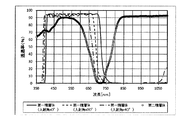
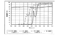
0.21mmの厚みを有するホウケイ酸ガラスでできた透明ガラス基板(SCHOTT社製、製品名:D263)の一方の主面にSiO2膜とTiO2膜とが交互に積層された近赤外線反射膜R1を蒸着法により形成した。このようにして、実施例1に係る第一積層体を作製した。実施例1に係る第一積層体の近赤外線反射膜R1の厚みは、5μmであった。また、実施例1に係る第一積層体の近赤外線反射膜R1は、17層のSiO2膜と17層のTiO2膜を含んでいた。実施例1に係る第一積層体の波長350〜1100nmにおける分光透過率を、分光光度計(日本分光社製、型式:V−670)を用いて測定した。この測定において、実施例1に係る第一積層体には、0°、30°、及び40°の入射角で光を入射させた。得られた透過率スペクトルを図10に示す。
<Example 1>
(First laminate)
A near-infrared reflective film in which SiO 2 film and TiO 2 film are alternately laminated on one main surface of a transparent glass substrate (manufactured by SCHOTT, product name: D263) made of borosilicate glass having a thickness of 0.21 mm. R1 was formed by a vapor deposition method. In this way, the first laminated body according to Example 1 was produced. The thickness of the near-infrared reflective film R1 of the first laminated body according to Example 1 was 5 μm. Further, the near-infrared reflective film R1 of the first laminated body according to Example 1 contained 17 layers of SiO 2 film and 17 layers of TiO 2 film. The spectral transmittance of the first laminated body according to Example 1 at a wavelength of 350 to 1100 nm was measured using a spectrophotometer (manufactured by JASCO Corporation, model: V-670). In this measurement, light was incident on the first laminated body according to Example 1 at incident angles of 0 °, 30 °, and 40 °. The obtained transmittance spectrum is shown in FIG.
実施例1に係る第一積層体に40°の入射角で入射する光の透過率スペクトルにおいて波長490nm付近にリップルが生じているものの、光の入射角がいずれの場合にも、450〜600nmの波長範囲における分光透過率の平均値は80%を超えていた。一方で、入射角が40°のときの実施例1に係る第一積層体の透過率スペクトルにおいて、波長約410nmに分光透過率が約69%である極小値を有していた。この透過率スペクトルにおいて、分光透過率が95%のラインをベースラインと仮定した場合、この極小値を含み下に凸となった部分は、ベースラインから20ポイント以上低下した分光透過率を有し、約16nmの半値全幅を有していた。 Although ripples occur in the wavelength vicinity of 490 nm in the transmittance spectrum of light incident on the first laminated body according to Example 1 at an incident angle of 40 °, the incident angle of light is 450 to 600 nm in any case. The average value of the spectral transmittance in the wavelength range exceeded 80%. On the other hand, in the transmittance spectrum of the first laminated body according to Example 1 when the incident angle was 40 °, the spectral transmittance had a minimum value of about 69% at a wavelength of about 410 nm. In this transmittance spectrum, assuming that a line having a spectral transmittance of 95% is the baseline, the portion that includes this minimum value and is convex downward has a spectral transmittance that is 20 points or more lower than the baseline. It had a full width at half maximum of about 16 nm.
第一積層体への入射角がX°のときに得られた透過率スペクトルにおいて波長600〜800nmの範囲において透過率がY%である波長を、特定波長としてλH R(X°,Y%)と定義した。実施例1に係る第一積層体の透過率スペクトルにおける波長600〜800nmの範囲の各特定波長を表1に示す。また、ΔλH R(70%)=λH R(0°,70%)−λH R(40°,70%)、ΔλH R(50%)=λH R(0°,50%)−λH R(40°,50%)、及びΔλH R(20%)=λH R(0°,20%)−λH R(40°,20%)と定義した。実施例1に係る第一積層体における、ΔλH R(70%)、ΔλH R(50%)及びΔλH R(20%)を表1に示す。 In the transmittance spectrum obtained when the angle of incidence on the first laminate is X °, the wavelength at which the transmittance is Y% in the wavelength range of 600 to 800 nm is defined as λ H R (X °, Y%). ). Table 1 shows each specific wavelength in the wavelength range of 600 to 800 nm in the transmittance spectrum of the first laminated body according to Example 1. Also, Δλ H R (70%) = λ H R (0 °, 70%) −λ H R (40 °, 70%), Δλ H R (50%) = λ H R (0 °, 50%) -λ H R (40 °, 50 %), and Δλ H R (20%) = λ H R (0 °, 20%) - λ H R (40 °, 20%) was defined as. Table 1 shows Δλ H R (70%), Δλ H R (50%), and Δλ H R (20%) in the first laminated body according to Example 1.
第一積層体への入射角がW°のときに得られた透過率スペクトルにおいて波長350〜450nmの範囲において透過率がZ%である波長を同様に特定波長としてλL R(W°,Z%)と定義した。実施例1に係る第一積層体の透過率スペクトルにおける波長350〜450nmの範囲の各特定波長を表1に示す。また、ΔλL R(70%)=λL R(0°,70%)−λL R(40°,70%)、ΔλL R(50%)=λL R(0°,50%)−λL R(40°,50%)、及びΔλL R(20%)=λL R(0°,20%)−λL R(40°,20%)と定義した。実施例1に係る第一積層体における、ΔλL R(70%)、ΔλL R(50%)、及びΔλL R(20%)を表1に示す。 In the transmittance spectrum obtained when the angle of incidence on the first laminated body is W °, a wavelength having a transmittance of Z% in the wavelength range of 350 to 450 nm is also set as a specific wavelength, and λ L R (W °, Z %) Was defined. Table 1 shows each specific wavelength in the wavelength range of 350 to 450 nm in the transmittance spectrum of the first laminated body according to Example 1. Also, Δλ L R (70%) = λ L R (0 °, 70%) −λ L R (40 °, 70%), Δλ L R (50%) = λ L R (0 °, 50%) -λ L R (40 °, 50 %), and Δλ L R (20%) = λ L R (0 °, 20%) - λ L R (40 °, 20%) was defined as. Table 1 shows Δλ L R (70%), Δλ L R (50%), and Δλ L R (20%) in the first laminated body according to Example 1.
(第二積層体)
波長700〜750nmに吸収ピークを持ち、可視域の吸収が少なく、メチルエチルケトン(MEK)に可溶な有機色素(シアニン系、スクアリリウム系、フタロシアニン系、及びジインモニウム系の有機色素から選択される1種類以上の有機色素)を組合せ、溶媒としてMEKを用い、固形分比で99重量%のポリビニルブチラール(PVB)を添加し、その後2時間撹拌して、コーティング液a1を得た。塗膜化して分光特性を測定した際に図10の第二積層体の分光スペクトル特性が得られるように各有機色素の含有量と配合比を決めた。
(Second laminate)
One or more selected from organic dyes (cyanine-based, squarylium-based, phthalocyanine-based, and diimmonium-based organic dyes) that have an absorption peak at a wavelength of 700 to 750 nm, have little absorption in the visible region, and are soluble in methyl ethyl ketone (MEK). (Organic dye) was combined, MEK was used as a solvent, polyvinyl butyral (PVB) having a solid content ratio of 99% by weight was added, and then the mixture was stirred for 2 hours to obtain a coating liquid a1. The content and compounding ratio of each organic dye were determined so that the spectral characteristics of the second laminate shown in FIG. 10 could be obtained when the coating film was formed and the spectral characteristics were measured.
このコーティング液a1を、0.21mmの厚みを有するホウケイ酸ガラスでできた透明ガラス基板(SCHOTT社製、製品名:D263)の一方の主面に、スピンコーティングにより塗布して塗膜を形成した。この塗膜を140℃の環境に0.5時間曝して、塗膜を乾燥及び硬化させ吸収膜A1を形成した。このようにして、実施例1に係る第二積層体を作製した。吸収膜A1の厚みは3μmであった。実施例1に係る第二積層体の波長350〜1100nmにおける分光透過率を、分光光度計(日本分光社製、型式:V−670)を用いて測定した。この測定において、実施例1に係る第二積層体には、0°、30°、及び40°の入射角で光を入射させたが、いずれの入射角でも実質的に同一の透過率スペクトルが得られた。入射角が0°のときに得られた透過率スペクトルを図10に示す。図10に示す通り、450〜600nmの波長範囲における実施例1に係る第二積層体の分光透過率の平均値は75%を超えていた。実施例1に係る第二積層体は、波長約700nm及び波長約760nmにおいて吸収ピークを有していた。加えて、実施例1に係る第二積層体は、波長約410nmにおいて吸収ピークを有していた。 This coating liquid a1 was applied to one main surface of a transparent glass substrate (manufactured by SCHOTT, product name: D263) made of borosilicate glass having a thickness of 0.21 mm by spin coating to form a coating film. .. The coating film was exposed to an environment of 140 ° C. for 0.5 hours to dry and cure the coating film to form an absorption film A1. In this way, the second laminated body according to Example 1 was produced. The thickness of the absorption film A1 was 3 μm. The spectral transmittance of the second laminate according to Example 1 at a wavelength of 350 to 1100 nm was measured using a spectrophotometer (manufactured by JASCO Corporation, model: V-670). In this measurement, light was incident on the second laminate according to Example 1 at incident angles of 0 °, 30 °, and 40 °, but substantially the same transmittance spectrum was obtained at all incident angles. Obtained. The transmittance spectrum obtained when the incident angle is 0 ° is shown in FIG. As shown in FIG. 10, the average value of the spectral transmittance of the second laminated body according to Example 1 in the wavelength range of 450 to 600 nm exceeded 75%. The second laminate according to Example 1 had an absorption peak at a wavelength of about 700 nm and a wavelength of about 760 nm. In addition, the second laminate according to Example 1 had an absorption peak at a wavelength of about 410 nm.
第二積層体への入射角がX°のときに得られた透過率スペクトルにおいて、波長600〜800nmの範囲において透過率がY%である波長を特定波長としてλH A(X°,Y%)と定義した。実施例1に係る第二積層体の透過率スペクトルにおける波長600〜800nmの範囲の各特定波長を表1に示す。実施例1に係る第二積層体の透過率スペクトルの、波長711nm(=λH R(0°,70%))、波長714nm(=λH R(0°,50%))、波長721nm(=λH R(0°,20%))、波長655nm(=λH R(40°,70%))、波長666nm(=λH R(40°,50%))、波長677nm(=λH R(40°,20%))、波長413nm(=λL R(0°,70%))、波長411nm(=λL R(0°,50%))、波長403nm(=λL R(0°,20%))、波長410nm(=λL R(40°,70%))、波長393nm(=λL R(40°,50%))、及び波長384nm(=λL R(40°,20%))における透過率を表1に示す。
In transmission spectrum obtained when the incident angle is X ° to the second laminate, λ H A (X ° wavelength transmittance is Y% as the specific wavelength in the wavelength range of 600 to 800 nm, Y% ). Table 1 shows each specific wavelength in the wavelength range of 600 to 800 nm in the transmittance spectrum of the second laminate according to Example 1. Wavelength 711 nm (= λ H R (0 °, 70%)), wavelength 714 nm (= λ H R (0 °, 50%)), wavelength 721 nm (= λ H R (0 °, 50%)) of the transmission spectrum of the second laminate according to Example 1. = Λ H R (0 °, 20%)), wavelength 655 nm (= λ H R (40 °, 70%)), wavelength 666 nm (= λ H R (40 °, 50%)), wavelength 677 nm (= λ) H R (40 °, 20%)), wavelength 413 nm (= λ L R (0 °, 70%)), wavelength 411 nm (= λ L R (0 °, 50%)), wavelength 403 nm (= λ L R) (0 °, 20%)),
(赤外線カットフィルタ)
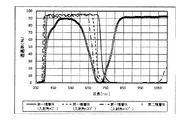
実施例1に係る第一積層体の透明ガラス基板の近赤外線反射膜R1が形成されていない主面に、第二積層体の作製と同様にして吸収膜A1を形成した。このようにして、実施例1に係る赤外線カットフィルタを作製した。実施例1に係る赤外線カットフィルタの波長350〜1100nmにおける分光透過率を、分光光度計(日本分光社製、型式:V−670)を用いて測定した。この測定において、実施例1に係る赤外線カットフィルタには、0°、30°、及び40°の入射角で光を入射させた。得られた透過率スペクトルを図11に示す。
(Infrared cut filter)
An absorption film A1 was formed on the main surface of the transparent glass substrate of the first laminated body according to Example 1 on which the near-infrared reflective film R1 was not formed, in the same manner as in the production of the second laminated body. In this way, the infrared cut filter according to Example 1 was produced. The spectral transmittance of the infrared cut filter according to Example 1 at a wavelength of 350 to 1100 nm was measured using a spectrophotometer (manufactured by JASCO Corporation, model: V-670). In this measurement, light was incident on the infrared cut filter according to Example 1 at incident angles of 0 °, 30 °, and 40 °. The obtained transmittance spectrum is shown in FIG.
赤外線カットフィルタへの入射角がX°のときに得られた透過率スペクトルにおいて波長600〜800nmの範囲において透過率がY%である波長を特定波長としてλH(X°,Y%)と定義した。表4に示す通り、波長λH(0°,70%)=614nm、波長λH(40°,70%)=612nmであり、それらの差の絶対値を|ΔλH(70%)|と定義すると、|ΔλH(70%)|=2nmであった。波長λH(0°,50%)=638nm、波長λH(40°,50%)=635nmであり、それらの差の絶対値を|ΔλH(50%)|と定義すると、|ΔλH(50%)|=3nmであった。波長λH(0°,20%)=672nm、波長λH(40°,20%)=658nmであり、それらの差の絶対値を|ΔλH(20%)|とすると、|ΔλH(20%)|=14nmであった。 In the transmittance spectrum obtained when the angle of incidence on the infrared cut filter is X °, the wavelength with a transmittance of Y% in the wavelength range of 600 to 800 nm is defined as λ H (X °, Y%) as a specific wavelength. bottom. As shown in Table 4, the wavelength λ H (0 °, 70%) = 614 nm and the wavelength λ H (40 °, 70%) = 612 nm, and the absolute value of the difference is | Δλ H (70%) | By definition, | Δλ H (70%) | = 2 nm. Wavelength λ H (0 °, 50% ) = 638nm, the wavelength λ H (40 °, 50% ) was = 635 nm, the absolute value of their difference and | Δλ H (50%) | and Defining, | [Delta] [lambda] H (50%) | = 3 nm. If the wavelength λ H (0 °, 20%) = 672 nm and the wavelength λ H (40 °, 20%) = 658 nm, and the absolute value of the difference is | Δλ H (20%) |, then | Δλ H ( 20%) | = 14 nm.
<実施例2>
(第一積層体)
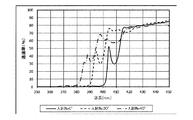
0.21mmの厚みを有するホウケイ酸ガラスでできた透明ガラス基板(SCHOTT社製、製品名:D263)の一方の主面に、SiO2膜とTiO2膜とが交互に積層された実施例1に記載の近赤外線反射膜R1とは異なる近赤外線反射膜R2を蒸着法により形成した。このようにして、実施例2に係る第一積層体を作製した。実施例2に係る第一積層体の近赤外線反射膜R2の厚みは、5μmであった。また、実施例2に係る第一積層体の近赤外線反射膜R2は、17層のSiO2膜と17層のTiO2膜を含んでいた。実施例2に係る第一積層体の波長350〜1100nmにおける分光透過率を実施例1と同様に測定した。得られた透過率スペクトルを図12に示す。
<Example 2>
(First laminate)
Example 1 in which SiO 2 film and TiO 2 film are alternately laminated on one main surface of a transparent glass substrate (manufactured by SCHOTT, product name: D263) made of borosilicate glass having a thickness of 0.21 mm. A near-infrared reflective film R2 different from the near-infrared reflective film R1 described in the above was formed by a vapor deposition method. In this way, the first laminated body according to Example 2 was produced. The thickness of the near-infrared reflective film R2 of the first laminated body according to Example 2 was 5 μm. Further, the near-infrared reflective film R2 of the first laminated body according to Example 2 contained 17 layers of SiO 2 film and 17 layers of TiO 2 film. The spectral transmittance of the first laminated body according to Example 2 at a wavelength of 350 to 1100 nm was measured in the same manner as in Example 1. The obtained transmittance spectrum is shown in FIG.
実施例2に係る第一積層体に関する透過率スペクトルにおいて、光の入射角がいずれの場合にも、450〜600nmの波長範囲における分光透過率の平均値は80%を超えていた。実施例2に係る第一積層体の透過率スペクトルにおける波長600〜800nmの範囲の各特定波長並びにΔλH R(70%)、ΔλH R(50%)及びΔλH R(20%)を表1に示す。また、実施例2に係る第一積層体の透過率スペクトルにおける波長350〜450nmの範囲の各特定波長並びにΔλL R(70%)、ΔλL R(50%)、及びΔλL R(20%)を表1に示す。 In the transmittance spectrum of the first laminated body according to Example 2, the average value of the spectral transmittance in the wavelength range of 450 to 600 nm exceeded 80% in any case of the incident angle of light. Tables show each specific wavelength in the wavelength range of 600 to 800 nm and Δλ H R (70%), Δλ H R (50%), and Δλ H R (20%) in the transmittance spectrum of the first laminated body according to Example 2. Shown in 1. Further, each specific wavelength in the wavelength range of 350 to 450 nm in the transmittance spectrum of the first laminated body according to Example 2, Δλ L R (70%), Δλ L R (50%), and Δλ L R (20%). ) Is shown in Table 1.
(第二積層体)
波長700〜750nmに吸収ピークを持ち、可視域の吸収が少なく、MEKに可溶な有機色素からなり、実施例1で使用した有機色素の組合せとは異なる、吸収性物質を組合せ、溶媒としてMEKを用い、固形分比で99重量%のPVBを添加し、その後2時間撹拌して、コーティング液a2を得た。塗膜化して分光特性を測定した際に図12の第二積層体の分光スペクトル特性が得られるように有機色素の含有量と配合比を決めた。
(Second laminate)
It has an absorption peak at a wavelength of 700 to 750 nm, has little absorption in the visible region, and is composed of an organic dye that is soluble in MEK. To obtain a coating liquid a2, 99% by weight of PVB was added in terms of solid content, and the mixture was then stirred for 2 hours. The content and compounding ratio of the organic dye were determined so that the spectral characteristics of the second laminate shown in FIG. 12 could be obtained when the coating film was formed and the spectral characteristics were measured.
コーティング液a2を0.21mmの厚みを有するホウケイ酸ガラスでできた透明ガラス基板(SCHOTT社製、製品名:D263)の一方の主面に、スピンコーティングにより塗布して塗膜を形成した。この塗膜を140℃の環境に0.5時間曝して、塗膜を乾燥及び硬化させ吸収膜A2を形成した。このようにして、実施例2に係る第二積層体を作製した。吸収膜A2の厚みは3μmであった。実施例2に係る第二積層体の波長350〜1100nmにおける分光透過率を、実施例1と同様にして測定した。この測定において、実施例2に係る第二積層体には、0°、30°、及び40°の入射角で光を入射させたが、いずれの入射角でも実質的に同一の透過率スペクトルが得られた。入射角が0°のときに得られた透過率スペクトルを図12に示す。図12に示す通り、450〜600nmの波長範囲における実施例2に係る第二積層体の分光透過率の平均値は75%を超えていた。実施例2に係る第二積層体は、波長約710nmにおいて吸収ピークを有していた。加えて、実施例2に係る第二積層体は、波長約420nmにおいて吸収ピークを有していた。 A coating film a2 was applied to one main surface of a transparent glass substrate (manufactured by SCHOTT, product name: D263) made of borosilicate glass having a thickness of 0.21 mm by spin coating to form a coating film. The coating film was exposed to an environment of 140 ° C. for 0.5 hours to dry and cure the coating film to form an absorption film A2. In this way, the second laminated body according to Example 2 was produced. The thickness of the absorption film A2 was 3 μm. The spectral transmittance of the second laminate according to Example 2 at a wavelength of 350 to 1100 nm was measured in the same manner as in Example 1. In this measurement, light was incident on the second laminate according to Example 2 at incident angles of 0 °, 30 °, and 40 °, but substantially the same transmittance spectrum was obtained at all incident angles. Obtained. The transmittance spectrum obtained when the incident angle is 0 ° is shown in FIG. As shown in FIG. 12, the average value of the spectral transmittance of the second laminated body according to Example 2 in the wavelength range of 450 to 600 nm exceeded 75%. The second laminate according to Example 2 had an absorption peak at a wavelength of about 710 nm. In addition, the second laminate according to Example 2 had an absorption peak at a wavelength of about 420 nm.
第二積層体への入射角がW°のときに得られた透過率スペクトルにおいて波長350〜450nmの範囲において透過率がZ%である波長を同様に特定波長としてλL A(W°,Z%)と定義した。実施例2に係る第二積層体の透過率スペクトルにおける波長600〜800nmの範囲の各特定波長及びλL A(0°,70%)を表1に示す。実施例2に係る第二積層体の透過率スペクトルの、波長715nm(=λH R(0°,70%))、波長720nm(=λH R(0°,50%))、波長731nm(=λH R(0°,20%))、波長658nm(=λH R(40°,70%))、波長670nm(=λH R(40°,50%))、波長684nm(=λH R(40°,20%))、波長406nm(=λL R(0°,70%))、波長405nm(=λL R(0°,50%))、波長402nm(=λL R(0°,20%))、波長389nm(=λL R(40°,70%))、波長387nm(=λL R(40°,50%))、及び波長385nm(=λL R(40°,20%))における透過率を表1に示す。 Second λ L A (W ° wavelength transmittance is Z% as well as a specific wavelength in the wavelength range of 350~450nm incidence angle in transmission spectrum obtained when the W ° to laminate, Z %) Was defined. Each specific wavelength and λ L A (0 °, 70 %) of the wavelength range of 600~800nm in transmittance spectrum of the second laminate according to Example 2 are shown in Table 1. Wavelength 715 nm (= λ H R (0 °, 70%)), wavelength 720 nm (= λ H R (0 °, 50%)), wavelength 731 nm (= λ H R (0 °, 50%)) of the transmission spectrum of the second laminate according to Example 2. = Λ H R (0 °, 20%)), wavelength 658 nm (= λ H R (40 °, 70%)), wavelength 670 nm (= λ H R (40 °, 50%)), wavelength 684 nm (= λ) H R (40 °, 20%)), wavelength 406 nm (= λ L R (0 °, 70%)), wavelength 405 nm (= λ L R (0 °, 50%)), wavelength 402 nm (= λ L R) (0 °, 20%)), wavelength 389 nm (= λ L R (40 °, 70%)), wavelength 387 nm (= λ L R (40 °, 50%)), and wavelength 385 nm (= λ L R (= λ L R)) Table 1 shows the transmission rate at 40 °, 20%)).
(赤外線カットフィルタ)
実施例2に係る第一積層体の透明ガラス基板の近赤外線反射膜R2が形成されていない主面に、第二積層体と同様にして吸収膜A2を形成した。実施例2に係る赤外線カットフィルタの波長350〜1100nmにおける分光透過率を実施例1と同様に測定した。得られた透過率スペクトルを図13に示す。
(Infrared cut filter)
An absorption film A2 was formed on the main surface of the transparent glass substrate of the first laminated body according to Example 2 on which the near-infrared reflective film R2 was not formed, in the same manner as in the second laminated body. The spectral transmittance of the infrared cut filter according to Example 2 at a wavelength of 350 to 1100 nm was measured in the same manner as in Example 1. The obtained transmittance spectrum is shown in FIG.
表4に示す通り、実施例2に係る赤外線カットフィルタの透過率スペクトルにおいて、波長λH(0°,70%)=621nm、波長λH(40°,70%)=618nmであり、それらの差の絶対値|ΔλH(70%)|=3nmであった。波長λH(0°,50%)=644nm、波長λH(40°,50%)=640nmであり、それらの差の絶対値|ΔλH(50%)|=4nmであった。波長λH(0°,20%)=676nm、波長λH(40°,20%)=663nmであり、それらの差の絶対値|ΔλH(20%)|=13nmであった。 As shown in Table 4, in the transmittance spectrum of the infrared cut filter according to Example 2, the wavelength λ H (0 °, 70%) = 621 nm and the wavelength λ H (40 °, 70%) = 618 nm. The absolute value of the difference | Δλ H (70%) | = 3 nm. The wavelength λ H (0 °, 50%) = 644 nm, the wavelength λ H (40 °, 50%) = 640 nm, and the absolute value of the difference | Δλ H (50%) | = 4 nm. The wavelength λ H (0 °, 20%) = 676 nm, the wavelength λ H (40 °, 20%) = 663 nm, and the absolute value of the difference | Δλ H (20%) | = 13 nm.
<実施例3>
(第一積層体)
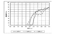
0.21mmの厚みを有するホウケイ酸ガラスでできた透明ガラス基板の一方の主面に、SiO2膜とTiO2膜とが交互に積層された実施例1及び2に記載の近赤外線反射膜R1及びR2とは異なる近赤外線反射膜R3を蒸着法により形成した。このようにして、実施例3に係る第一積層体を作製した。実施例3に係る第一積層体の近赤外線反射膜R3の厚みは、6μmであった。また、実施例3に係る第一積層体の近赤外線反射膜R3は、20層のSiO2膜と20層のTiO2膜を含んでいた。実施例3に係る第一積層体の波長350〜1100nmにおける分光透過率を実施例1と同様に測定した。得られた透過率スペクトルを図14に示す。
<Example 3>
(First laminate)
The near-infrared reflective film R1 according to Examples 1 and 2 in which SiO 2 film and TiO 2 film are alternately laminated on one main surface of a transparent glass substrate made of borosilicate glass having a thickness of 0.21 mm. And a near-infrared reflective film R3 different from R2 was formed by a vapor deposition method. In this way, the first laminated body according to Example 3 was produced. The thickness of the near-infrared reflective film R3 of the first laminated body according to Example 3 was 6 μm. Further, the near-infrared reflective film R3 of the first laminated body according to Example 3 contained 20 layers of SiO 2 film and 20 layers of TiO 2 film. The spectral transmittance of the first laminated body according to Example 3 at a wavelength of 350 to 1100 nm was measured in the same manner as in Example 1. The obtained transmittance spectrum is shown in FIG.
実施例3に係る第一積層体において、光の入射角がいずれの場合にも、450〜600nmの波長範囲における分光透過率の平均値は80%を超えていた。実施例3に係る第一積層体の透過率スペクトルにおける波長600〜800nmの範囲の各特定波長並びにΔλH R(70%)、ΔλH R(50%)及びΔλH R(20%)を表1に示す。また、実施例3に係る第一積層体の透過率スペクトルにおける波長350〜450nmの範囲の各特定波長並びにΔλL R(70%)、ΔλL R(50%)、及びΔλL R(20%)を表1に示す。 In the first laminated body according to Example 3, the average value of the spectral transmittance in the wavelength range of 450 to 600 nm exceeded 80% in any case of the incident angle of light. Tables show each specific wavelength in the wavelength range of 600 to 800 nm and Δλ H R (70%), Δλ H R (50%), and Δλ H R (20%) in the transmittance spectrum of the first laminated body according to Example 3. Shown in 1. Further, each specific wavelength in the wavelength range of 350 to 450 nm in the transmittance spectrum of the first laminated body according to Example 3, Δλ L R (70%), Δλ L R (50%), and Δλ L R (20%). ) Is shown in Table 1.
(第二積層体)
0.21mmの厚みを有するホウケイ酸ガラスでできた透明ガラス基板(SCHOTT社製、製品名:D263)の一方の主面に、フェニルホスホン酸銅微粒子を含むコーティング液b1を塗布し、塗膜を乾燥及び硬化させて吸収膜B1(第二吸収膜)を形成した。
(Second laminate)
A coating liquid b1 containing fine copper phenylphosphonate is applied to one main surface of a transparent glass substrate (manufactured by SCHOTT, product name: D263) made of borosilicate glass having a thickness of 0.21 mm to form a coating film. It was dried and cured to form an absorption film B1 (second absorption film).
コーティング液b1は以下のようにして調製した。酢酸銅一水和物1.1gとテトラヒドロフラン(THF)60gとを混合して3時間撹拌し酢酸銅溶液を得た。次に、得られた酢酸銅溶液に、プライサーフA208F(第一工業製薬社製)を2.3g加えて30分間撹拌し、b11液を得た。また、フェニルホスホン酸(東京化成工業株式会社製)0.6gにTHF10gを加えて30分撹拌し、b12液を得た。次に、b11液を撹拌しながらb11液にb12液を加え、室温で1分間撹拌した。次に、この溶液にトルエン45gを加えた後、室温で1分間撹拌し、b13液を得た。このb13液をフラスコに入れてオイルバス(東京理化器械社製、型式:OSB−2100)で加温しながら、ロータリーエバポレータ(東京理化器械社製、型式:N−1110SF)によって、25分間脱溶媒処理を行った。オイルバスの設定温度は、120℃に調整した。その後、フラスコの中から脱溶媒処理後の溶液を取り出した。取り出した溶液に、シリコーン樹脂(信越化学工業社製、製品名:KR−300)を4.4g添加し、室温で30分間撹拌し、コーティング液b1を得た。 The coating liquid b1 was prepared as follows. 1.1 g of copper acetate monohydrate and 60 g of tetrahydrofuran (THF) were mixed and stirred for 3 hours to obtain a copper acetate solution. Next, 2.3 g of Prysurf A208F (manufactured by Dai-ichi Kogyo Seiyaku Co., Ltd.) was added to the obtained copper acetate solution and stirred for 30 minutes to obtain a b11 solution. Further, 10 g of THF was added to 0.6 g of phenylphosphonic acid (manufactured by Tokyo Chemical Industry Co., Ltd.) and stirred for 30 minutes to obtain a b12 solution. Next, the b12 solution was added to the b11 solution while stirring the b11 solution, and the mixture was stirred at room temperature for 1 minute. Next, 45 g of toluene was added to this solution, and the mixture was stirred at room temperature for 1 minute to obtain a b13 solution. This b13 solution is placed in a flask and heated in an oil bath (manufactured by Tokyo Rika Kikai Co., Ltd., model: OSB-2100) while being desolvated for 25 minutes by a rotary evaporator (manufactured by Tokyo Rika Kikai Co., Ltd., model: N-1110SF). Processing was performed. The set temperature of the oil bath was adjusted to 120 ° C. Then, the desolvated solution was taken out from the flask. 4.4 g of a silicone resin (manufactured by Shin-Etsu Chemical Co., Ltd., product name: KR-300) was added to the removed solution, and the mixture was stirred at room temperature for 30 minutes to obtain a coating liquid b1.
得られたコーティング液b1を、透明ガラス基板の一方の主面に、ダイコーティングによって塗布し、次に、コーティング液b1の未乾燥の塗膜を有する透明ガラス基板をオーブンに入れて、85℃で3時間、次に125℃で3時間、次に150℃で1時間、次に170℃で3時間の条件で塗膜に対して加熱処理を行い、塗膜を硬化させ吸収膜B1(第二吸収膜)を形成した。第二吸収膜である吸収膜B1の厚みは50μmであった。次に、第二吸収膜である吸収膜B1の上に、実施例2で使用したコーティング液a2をスピンコーティングにより塗布して塗膜を形成した。この塗膜を140℃の環境に0.5時間曝して、塗膜を乾燥及び硬化させ吸収膜A2(第一吸収膜)を形成した。吸収膜A2の厚みは3μmであった。このようにして、実施例3に係る第二積層体を作製した。すなわち、実施例3に係る第二積層体の吸収膜は、厚みが50μmの吸収膜B1(第二吸収膜)及び厚みが3μmの吸収膜A2(第一吸収膜)を含んでいた。 The obtained coating liquid b1 is applied to one main surface of the transparent glass substrate by die coating, and then the transparent glass substrate having the undried coating film of the coating liquid b1 is placed in an oven at 85 ° C. The coating film was heat-treated for 3 hours, then at 125 ° C. for 3 hours, then at 150 ° C. for 1 hour, and then at 170 ° C. for 3 hours to cure the coating film and absorb film B1 (second). Absorption film) was formed. The thickness of the absorption film B1 which is the second absorption film was 50 μm. Next, the coating liquid a2 used in Example 2 was applied onto the absorption film B1 which is the second absorption film by spin coating to form a coating film. This coating film was exposed to an environment of 140 ° C. for 0.5 hours to dry and cure the coating film to form an absorption film A2 (first absorption film). The thickness of the absorption film A2 was 3 μm. In this way, the second laminated body according to Example 3 was produced. That is, the absorption film of the second laminated body according to Example 3 contained an absorption film B1 (second absorption film) having a thickness of 50 μm and an absorption film A2 (first absorption film) having a thickness of 3 μm.
実施例3に係る第二積層体の波長350〜1100nmにおける分光透過率を、実施例1と同様にして測定した。この測定において、実施例3に係る第二積層体には、0°、30°、及び40°の入射角で光を入射させたが、いずれの入射角でも実質的に同一の透過率スペクトルが得られた。入射角が0°のときに得られた透過率スペクトルを図14に示す。図14に示す通り、450〜600nmの波長範囲における実施例3に係る第二積層体の分光透過率の平均値は75%を超えていた。実施例3に係る第二積層体の透過率スペクトルは、波長約700〜約770nmの範囲に及ぶ幅広な吸収ピークを有していた。また実施例3に係る第二積層体は、波長約410nmにおいて吸収ピークを有していた。 The spectral transmittance of the second laminate according to Example 3 at a wavelength of 350 to 1100 nm was measured in the same manner as in Example 1. In this measurement, light was incident on the second laminate according to Example 3 at incident angles of 0 °, 30 °, and 40 °, but substantially the same transmittance spectrum was obtained at all incident angles. Obtained. The transmittance spectrum obtained when the incident angle is 0 ° is shown in FIG. As shown in FIG. 14, the average value of the spectral transmittance of the second laminated body according to Example 3 in the wavelength range of 450 to 600 nm exceeded 75%. The transmittance spectrum of the second laminate according to Example 3 had a wide absorption peak in the wavelength range of about 700 to about 770 nm. Further, the second laminate according to Example 3 had an absorption peak at a wavelength of about 410 nm.
実施例3に係る第二積層体の透過率スペクトルにおける波長600〜800nmの範囲の各特定波長及び実施例3に係る第二積層体の透過率スペクトルにおける波長350〜450nmの範囲の各特定波長を表1に示す。実施例3に係る第二積層体の透過率スペクトルの、波長727nm(=λH R(0°,70%))、波長738nm(=λH R(0°,50%))、波長766nm(=λH R(0°,20%))、波長672nm(=λH R(40°,70%))、波長685nm(=λH R(40°,50%))、波長717nm(=λH R(40°,20%))、波長406nm(=λL R(0°,70%))、波長405nm(=λL R(0°,50%))、波長402nm(=λL R(0°,20%))、波長389nm(=λL R(40°,70%))、波長387nm(=λL R(40°,50%))、及び波長385nm(=λL R(40°,20%))における透過率を表1に示す。 Each specific wavelength in the wavelength range of 600 to 800 nm in the transmittance spectrum of the second laminate according to Example 3 and each specific wavelength in the wavelength range of 350 to 450 nm in the transmittance spectrum of the second laminate according to Example 3. It is shown in Table 1. Wavelength 727 nm (= λ H R (0 °, 70%)), wavelength 738 nm (= λ H R (0 °, 50%)), wavelength 766 nm (= λ H R (0 °, 50%)) of the transmission spectrum of the second laminate according to Example 3. = Λ H R (0 °, 20%)), wavelength 672 nm (= λ H R (40 °, 70%)), wavelength 685 nm (= λ H R (40 °, 50%)), wavelength 717 nm (= λ) H R (40 °, 20%)), wavelength 406 nm (= λ L R (0 °, 70%)), wavelength 405 nm (= λ L R (0 °, 50%)), wavelength 402 nm (= λ L R) (0 °, 20%)), wavelength 389 nm (= λ L R (40 °, 70%)), wavelength 387 nm (= λ L R (40 °, 50%)), and wavelength 385 nm (= λ L R (= λ L R)) Table 1 shows the transmission rate at 40 °, 20%)).
(赤外線カットフィルタ)
実施例3に係る第一積層体の透明ガラス基板の近赤外線反射膜が形成されていない主面に、第二積層体と同様にして吸収膜A2(第一吸収膜)及び吸収膜B1(第二吸収膜)からなる吸収膜を形成した。実施例3に係る赤外線カットフィルタの波長350〜1100nmにおける分光透過率を実施例1と同様に測定した。得られた透過率スペクトルを図15に示す。
(Infrared cut filter)
Absorption film A2 (first absorption film) and absorption film B1 (first absorption film) and absorption film B1 (first absorption film) in the same manner as in the second laminate on the main surface of the transparent glass substrate of the first laminate according to Example 3 in which the near-infrared reflective film is not formed. An absorption film composed of (two absorption films) was formed. The spectral transmittance of the infrared cut filter according to Example 3 at a wavelength of 350 to 1100 nm was measured in the same manner as in Example 1. The obtained transmittance spectrum is shown in FIG.
表4に示す通り、実施例3に係る赤外線カットフィルタの透過率スペクトルにおいて、波長λH(0°,70%)=612nm、波長λH(40°,70%)=607nmであり、それらの差の絶対値|ΔλH(70%)|=5nmであった。波長λH(0°,50%)=635nm、波長λH(40°,50%)=632nmであり、それらの差の絶対値|ΔλH(50%)|=3nmであった。波長λH(0°,20%)=669nm、波長λH(40°,20%)=661nmであり、それらの差の絶対値|ΔλH(20%)|=8nmであった。 As shown in Table 4, in the transmittance spectrum of the infrared cut filter according to Example 3, the wavelength λ H (0 °, 70%) = 612 nm and the wavelength λ H (40 °, 70%) = 607 nm. The absolute value of the difference | Δλ H (70%) | = 5 nm. The wavelength λ H (0 °, 50%) = 635 nm, the wavelength λ H (40 °, 50%) = 632 nm, and the absolute value of the difference | Δλ H (50%) | = 3 nm. The wavelength λ H (0 °, 20%) = 669 nm, the wavelength λ H (40 °, 20%) = 661 nm, and the absolute value of the difference | Δλ H (20%) | = 8 nm.
<実施例4>
(第一積層体)
0.21mmの厚みを有するホウケイ酸ガラスでできた透明ガラス基板(SCHOTT社製、製品名:D263)の一方の主面にSiO2膜とTiO2膜とが交互に積層された実施例2に係る近赤外線反射膜と同一の近赤外線反射膜R2を蒸着法により形成した。このようにして、実施例4に係る第一積層体を作製した。実施例4に係る第一積層体の波長350〜1100nmにおける分光透過率を実施例1と同様に測定した。得られた透過率スペクトルを図16に示す。実施例4に係る第一積層体に関する透過率スペクトルは実施例2に係る第一積層体に関する透過率スペクトルと同一であった。
<Example 4>
(First laminate)
In Example 2 in which SiO 2 film and TiO 2 film are alternately laminated on one main surface of a transparent glass substrate (manufactured by SCHOTT, product name: D263) made of borosilicate glass having a thickness of 0.21 mm. The same near-infrared reflective film R2 as the near-infrared reflective film was formed by a vapor deposition method. In this way, the first laminated body according to Example 4 was produced. The spectral transmittance of the first laminated body according to Example 4 at a wavelength of 350 to 1100 nm was measured in the same manner as in Example 1. The obtained transmittance spectrum is shown in FIG. The transmittance spectrum for the first laminate according to Example 4 was the same as the transmittance spectrum for the first laminate according to Example 2.
(第二積層体)
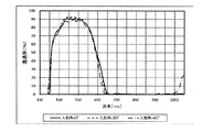
波長700〜750nmに吸収ピークを持ち、可視域の吸収が少なく、MEK(メチルエチルケトン)に可溶な有機色素であり、実施例2の吸収膜に含まれる有機色素の組合せと同一の有機色素の組合せからなる吸収性物質と、可視域の吸収が少なく、MEK(メチルエチルケトン)に可溶なベンゾフェノン系紫外線吸収性物質からなる紫外線吸収性物質と、を組合せ、溶媒としてMEKを用い、固形分比で99重量%のPVBを添加し、調合後2時間撹拌してコーティング液a3を得た。コーティング液a3の調製のために用いたベンゾフェノン系紫外線吸収性物質は、それのみをポリビニルブチラールに内包させて作製した紫外線吸収膜の分光透過率が、波長350〜450nmの範囲において、10%以下から70%以上に増加する特性を備えていた。その紫外線吸収膜の透過率スペクトルを図56に示す。
(Second laminate)
It is an organic dye that has an absorption peak at a wavelength of 700 to 750 nm, has little absorption in the visible region, and is soluble in MEK (methyl ethyl ketone), and is the same combination of organic dyes as the combination of organic dyes contained in the absorption film of Example 2. A combination of an absorbent substance consisting of an absorbent substance and an ultraviolet absorbing substance composed of a benzophenone-based ultraviolet absorbing substance which has little absorption in the visible region and is soluble in MEK (methyl ethyl ketone), uses MEK as a solvent, and has a solid content ratio of 99. PVB by weight was added, and the mixture was stirred for 2 hours after preparation to obtain a coating liquid a3. The benzophenone-based UV-absorbing substance used for the preparation of the coating liquid a3 has a spectral transmittance of 10% or less in the wavelength range of 350 to 450 nm of a UV-absorbing film prepared by encapsulating only it in polyvinyl butyral. It had the property of increasing to 70% or more. The transmittance spectrum of the ultraviolet absorbing film is shown in FIG.
コーティング液a3における有機色素及びベンゾフェノン系紫外線吸収性物質の含有量及び配合比は、塗膜化して分光特性を測定した際に図16の第二積層体の分光スペクトル特性が得られるように決めた。このコーティング液a3を、0.21mmの厚みを有するホウケイ酸ガラスでできた透明ガラス基板(SCHOTT社製、製品名:D263)の一方の主面に、スピンコーティングにより塗布して塗膜を形成した。この塗膜を140℃の環境に0.5時間曝して、塗膜を乾燥及び硬化させ吸収膜A3を形成した。このようにして、実施例4に係る第二積層体を作製した。吸収膜A3の厚みは3μmであった The content and compounding ratio of the organic dye and the benzophenone-based ultraviolet absorbing substance in the coating liquid a3 were determined so that the spectral spectral characteristics of the second laminate of FIG. 16 could be obtained when the coating was formed and the spectral characteristics were measured. .. This coating liquid a3 was applied to one main surface of a transparent glass substrate (manufactured by SCHOTT, product name: D263) made of borosilicate glass having a thickness of 0.21 mm by spin coating to form a coating film. .. The coating film was exposed to an environment of 140 ° C. for 0.5 hours to dry and cure the coating film to form an absorption film A3. In this way, the second laminated body according to Example 4 was produced. The thickness of the absorption membrane A3 was 3 μm.
実施例4に係る第二積層体の波長350〜1100nmにおける分光透過率を、実施例1と同様にして測定した。この測定において、実施例4に係る第二積層体には、0°、30°、及び40°の入射角で光を入射させたが、いずれの入射角でも実質的に同一の透過率スペクトルが得られた。入射角が0°のときに得られた透過率スペクトルを図16に示す。図16に示す通り、450〜600nmの波長範囲における実施例4に係る第二積層体の分光透過率の平均値は75%を超えていた。実施例4に係る第二積層体の透過率スペクトルは、波長約710nmに吸収ピークを有していた。実施例4に係る第二積層体の透過率スペクトルは、波長350〜450nmの範囲において分光透過率が70%から10%以下に低下する特性を有していた。 The spectral transmittance of the second laminate according to Example 4 at a wavelength of 350 to 1100 nm was measured in the same manner as in Example 1. In this measurement, light was incident on the second laminate according to Example 4 at incident angles of 0 °, 30 °, and 40 °, and substantially the same transmittance spectrum was obtained at all incident angles. Obtained. The transmittance spectrum obtained when the incident angle is 0 ° is shown in FIG. As shown in FIG. 16, the average value of the spectral transmittance of the second laminated body according to Example 4 in the wavelength range of 450 to 600 nm exceeded 75%. The transmittance spectrum of the second laminate according to Example 4 had an absorption peak at a wavelength of about 710 nm. The transmittance spectrum of the second laminated body according to Example 4 had a characteristic that the spectral transmittance decreased from 70% to 10% or less in the wavelength range of 350 to 450 nm.
実施例4に係る第二積層体の透過率スペクトルにおける波長600〜800nmの範囲の各特定波長及び実施例4に係る第二積層体の透過率スペクトルにおける波長350〜450nmの範囲の各特定波長を表1に示す。実施例4に係る第二積層体の透過率スペクトルの、波長715nm(=λH R(0°,70%))、波長720nm(=λH R(0°,50%))、波長731nm(=λH R(0°,20%))、波長658nm(=λH R(40°,70%))、波長670nm(=λH R(40°,50%))、波長684nm(=λH R(40°,20%))、波長406nm(=λL R(0°,70%))、波長405nm(=λL R(0°,50%))、波長402nm(=λL R(0°,20%))、波長389nm(=λL R(40°,70%))、波長387nm(=λL R(40°,50%))、及び波長385nm(=λL R(40°,20%))における透過率を表1に示す。 Each specific wavelength in the wavelength range of 600 to 800 nm in the transmittance spectrum of the second laminate according to Example 4 and each specific wavelength in the wavelength range of 350 to 450 nm in the transmittance spectrum of the second laminate according to Example 4 It is shown in Table 1. Wavelength 715 nm (= λ H R (0 °, 70%)), wavelength 720 nm (= λ H R (0 °, 50%)), wavelength 731 nm (= λ H R (0 °, 50%)) of the transmission spectrum of the second laminate according to Example 4. = Λ H R (0 °, 20%)), wavelength 658 nm (= λ H R (40 °, 70%)), wavelength 670 nm (= λ H R (40 °, 50%)), wavelength 684 nm (= λ) H R (40 °, 20%)), wavelength 406 nm (= λ L R (0 °, 70%)), wavelength 405 nm (= λ L R (0 °, 50%)), wavelength 402 nm (= λ L R) (0 °, 20%)), wavelength 389 nm (= λ L R (40 °, 70%)), wavelength 387 nm (= λ L R (40 °, 50%)), and wavelength 385 nm (= λ L R (= λ L R)) Table 1 shows the transmission rate at 40 °, 20%)).
(赤外線カットフィルタ)
実施例4に係る第一積層体の透明ガラス基板の近赤外線反射膜R2が形成されていない主面に、第二積層体と同様にして吸収膜A3を形成し、実施例4に係る赤外線カットフィルタを得た。実施例4に係る赤外線カットフィルタの波長350〜1100nmにおける分光透過率を実施例1と同様に測定した。得られた透過率スペクトルを図17に示す。
(Infrared cut filter)
An absorption film A3 is formed on the main surface of the transparent glass substrate of the first laminated body according to the fourth embodiment in the same manner as the second laminated body on the main surface where the near-infrared reflective film R2 is not formed, and the infrared ray is cut according to the fourth embodiment. I got a filter. The spectral transmittance of the infrared cut filter according to Example 4 at a wavelength of 350 to 1100 nm was measured in the same manner as in Example 1. The obtained transmittance spectrum is shown in FIG.
表4に示す通り、実施例4に係る赤外線カットフィルタの透過率スペクトルにおいて、波長λH(0°,70%)=621nm、波長λH(40°,70%)=620nmであり、それらの差の絶対値|ΔλH(70%)|=1nmであった。波長λH(0°,50%)=643nm、波長λH(40°,50%)=642nmであり、それらの差の絶対値|ΔλH(50%)|=1nmであった。波長λH(0°,20%)=676nm、波長λH(40°,20%)=663nmであり、それらの差の絶対値|ΔλH(20%)|=13nmであった。赤外線カットフィルタへの入射角がW°のときに得られた透過率スペクトルにおいて波長350〜450nmの範囲において透過率がZ%である波長をλL(W°,Z%)と定義した。表4に示す通り、波長λL(0°,70%)=426nm、波長λL(40°,70%)=433nmであり、それらの差の絶対値を|ΔλL(70%)|とすると、|ΔλL(70%)|=7nmであった。波長λL(0°,50%)=409nm、波長λL(40°,50%)=408nmであり、それらの差の絶対値を|ΔλL(50%)|とすると、|ΔλL(50%)|=1nmであった。波長λL(0°,20%)=404nm、波長λL(40°,20%)=398nmであり、それらの差の絶対値を|ΔλL(20%)|とすると、|ΔλL(20%)|=6nmであった。 As shown in Table 4, in the transmittance spectrum of the infrared cut filter according to Example 4, the wavelength λ H (0 °, 70%) = 621 nm and the wavelength λ H (40 °, 70%) = 620 nm. The absolute value of the difference | Δλ H (70%) | = 1 nm. The wavelength λ H (0 °, 50%) = 643 nm, the wavelength λ H (40 °, 50%) = 642 nm, and the absolute value of the difference | Δλ H (50%) | = 1 nm. The wavelength λ H (0 °, 20%) = 676 nm, the wavelength λ H (40 °, 20%) = 663 nm, and the absolute value of the difference | Δλ H (20%) | = 13 nm. In the transmittance spectrum obtained when the angle of incidence on the infrared cut filter is W °, the wavelength in which the transmittance is Z% in the wavelength range of 350 to 450 nm is defined as λ L (W °, Z%). As shown in Table 4, the wavelength λ L (0 °, 70%) = 426 nm, the wavelength λ L (40 °, 70%) = 433 nm, and the absolute value of the difference is | Δλ L (70%) | Then, | Δλ L (70%) | = 7 nm. If the wavelength λ L (0 °, 50%) = 409 nm and the wavelength λ L (40 °, 50%) = 408 nm, and the absolute value of the difference is | Δλ L (50%) |, then | Δλ L ( 50%) | = 1 nm. If the wavelength λ L (0 °, 20%) = 404 nm and the wavelength λ L (40 °, 20%) = 398 nm, and the absolute value of the difference is | Δλ L (20%) |, then | Δλ L ( 20%) | = 6 nm.
<実施例5>
(第一積層体)
0.21mmの厚みを有するホウケイ酸ガラスでできた透明ガラス基板(SCHOTT社製、製品名:D263)の一方の主面に、SiO2膜とTiO2膜とが交互に積層された実施例1〜4に記載の近赤外線反射膜R1〜R3とは異なる近赤外線反射膜R4を蒸着法により形成した。このようにして、実施例5に係る第一積層体を作製した。実施例5に係る第一積層体の近赤外線反射膜の厚みは、6μmであった。また、実施例5に係る第一積層体の近赤外線反射膜R4は、20層のSiO2膜と20層のTiO2膜を含んでいた。実施例5に係る第一積層体の波長350〜1100nmにおける分光透過率を実施例1と同様に測定した。得られた透過率スペクトルを図18に示す。
<Example 5>
(First laminate)
Example 1 in which SiO 2 film and TiO 2 film are alternately laminated on one main surface of a transparent glass substrate (manufactured by SCHOTT, product name: D263) made of borosilicate glass having a thickness of 0.21 mm. A near-infrared reflective film R4 different from the near-infrared reflective films R1 to R3 described in No. 4 was formed by a vapor deposition method. In this way, the first laminated body according to Example 5 was produced. The thickness of the near-infrared reflective film of the first laminated body according to Example 5 was 6 μm. Further, the near-infrared reflective film R4 of the first laminated body according to Example 5 contained 20 layers of SiO 2 film and 20 layers of TiO 2 film. The spectral transmittance of the first laminated body according to Example 5 at a wavelength of 350 to 1100 nm was measured in the same manner as in Example 1. The obtained transmittance spectrum is shown in FIG.
実施例5に係る第一積層体に関する透過率スペクトルにおいて、光の入射角がいずれの場合にも、450〜600nmの波長範囲における分光透過率の平均値は80%を超えていた。実施例5に係る第一積層体の透過率スペクトルにおける波長600〜800nmの範囲の各特定波長並びにΔλH R(70%)、ΔλH R(50%)及びΔλH R(20%)を表2に示す。また、実施例5に係る第一積層体の透過率スペクトルにおける波長350〜450nmの範囲の各特定波長並びにΔλL R(70%)、ΔλL R(50%)、及びΔλL R(20%)を表2に示す。 In the transmittance spectrum of the first laminated body according to Example 5, the average value of the spectral transmittance in the wavelength range of 450 to 600 nm exceeded 80% in any case of the incident angle of light. Tables show each specific wavelength in the wavelength range of 600 to 800 nm and Δλ H R (70%), Δλ H R (50%), and Δλ H R (20%) in the transmittance spectrum of the first laminate according to Example 5. Shown in 2. Further, each specific wavelength in the wavelength range of 350 to 450 nm in the transmittance spectrum of the first laminated body according to Example 5, Δλ L R (70%), Δλ L R (50%), and Δλ L R (20%). ) Is shown in Table 2.
(第二積層体)
実施例3で使用したコーティング液b1を、0.21mmの厚みを有するホウケイ酸ガラスでできた透明ガラス基板(SCHOTT社製、製品名:D263)の一方の主面に、ダイコーティングによって塗布して塗膜を形成した。この塗膜を85℃で3時間、次に125℃で3時間、次に150℃で1時間、次に170℃で3時間の条件で塗膜に対して加熱処理を行い、実施例3と同様に吸収膜B1を形成した。吸収膜B1の厚みは50μmであった。このようにして、実施例5に係る第二積層体の第二吸収膜である吸収膜B1を作製した。次に、吸収膜B1の上に、実施例4で使用したコーティング液a3をスピンコーティングにより塗布して塗膜を形成した。この塗膜を140℃の環境に0.5時間曝して、塗膜を乾燥及び硬化させ、実施例4と同様に吸収膜A3を形成した。このようにして、実施例5に係る第二積層体の第一吸収膜である吸収膜A3を作製した。吸収膜A3の厚みは3μmであった。このようにして、実施例5に係る第二積層体を作製した。すなわち、実施例5に係る第二積層体の吸収膜は、厚みが50μmの吸収膜B1(第二吸収膜)及び厚みが3μmの吸収膜A3(第一吸収膜)を含んでいた。
(Second laminate)
The coating liquid b1 used in Example 3 is applied to one main surface of a transparent glass substrate (manufactured by SCHOTT, product name: D263) made of borosilicate glass having a thickness of 0.21 mm by die coating. A coating film was formed. The coating film was heat-treated at 85 ° C. for 3 hours, then at 125 ° C. for 3 hours, then at 150 ° C. for 1 hour, and then at 170 ° C. for 3 hours. Similarly, the absorption film B1 was formed. The thickness of the absorption film B1 was 50 μm. In this way, the absorption film B1 which is the second absorption film of the second laminate according to Example 5 was produced. Next, the coating liquid a3 used in Example 4 was applied onto the absorption film B1 by spin coating to form a coating film. The coating film was exposed to an environment of 140 ° C. for 0.5 hours to dry and cure the coating film to form an absorption film A3 in the same manner as in Example 4. In this way, the absorption film A3, which is the first absorption film of the second laminated body according to Example 5, was produced. The thickness of the absorption film A3 was 3 μm. In this way, the second laminated body according to Example 5 was produced. That is, the absorption film of the second laminated body according to Example 5 included an absorption film B1 (second absorption film) having a thickness of 50 μm and an absorption film A3 (first absorption film) having a thickness of 3 μm.
実施例5に係る第二積層体の波長350〜1100nmにおける分光透過率を、実施例1と同様にして測定した。この測定において、実施例5に係る第二積層体には、0°、30°、及び40°の入射角で光を入射させたが、いずれの入射角でも実質的に同一の透過率スペクトルが得られた。入射角が0°のときに得られた透過率スペクトルを図18に示す。図18に示す通り、450〜600nmの波長範囲における実施例5に係る第二積層体の分光透過率の平均値は75%を超えていた。実施例5に係る第二積層体の透過率スペクトルは、波長約700nm〜約770nmの範囲に及ぶ幅広な吸収ピークを有していた。実施例5に係る第二積層体の透過率スペクトルは、波長350〜450nmの範囲において分光透過率が10%以下から70%以上に増加する特性を有していた。 The spectral transmittance of the second laminate according to Example 5 at a wavelength of 350 to 1100 nm was measured in the same manner as in Example 1. In this measurement, light was incident on the second laminate according to Example 5 at incident angles of 0 °, 30 °, and 40 °, and substantially the same transmittance spectrum was obtained at all incident angles. Obtained. The transmittance spectrum obtained when the incident angle is 0 ° is shown in FIG. As shown in FIG. 18, the average value of the spectral transmittance of the second laminated body according to Example 5 in the wavelength range of 450 to 600 nm exceeded 75%. The transmittance spectrum of the second laminate according to Example 5 had a wide absorption peak in the wavelength range of about 700 nm to about 770 nm. The transmittance spectrum of the second laminated body according to Example 5 had a characteristic that the spectral transmittance increased from 10% or less to 70% or more in the wavelength range of 350 to 450 nm.
実施例5に係る第二積層体の透過率スペクトルにおける波長600〜800nmの範囲の各特定波長及び実施例5に係る第二積層体の透過率スペクトルにおける波長350〜450nmの範囲の各特定波長を表2に示す。実施例5に係る第二積層体の透過率スペクトルの、波長727nm(=λH R(0°,70%))、波長738nm(=λH R(0°,50%))、波長766nm(=λH R(0°,20%))、波長672nm(=λH R(40°,70%))、波長685nm(=λH R(40°,50%))、波長717nm(=λH R(40°,20%))、波長406nm(=λL R(0°,70%))、波長405nm(=λL R(0°,50%))、波長402nm(=λL R(0°,20%))、波長389nm(=λL R(40°,70%))、波長387nm(=λL R(40°,50%))、及び波長385nm(=λL R(40°,20%))における透過率を表2に示す。 Each specific wavelength in the wavelength range of 600 to 800 nm in the transmittance spectrum of the second laminate according to Example 5 and each specific wavelength in the wavelength range of 350 to 450 nm in the transmittance spectrum of the second laminate according to Example 5 It is shown in Table 2. Wavelength 727 nm (= λ H R (0 °, 70%)), wavelength 738 nm (= λ H R (0 °, 50%)), wavelength 766 nm (= λ H R (0 °, 50%)) of the transmission spectrum of the second laminate according to Example 5. = Λ H R (0 °, 20%)), wavelength 672 nm (= λ H R (40 °, 70%)), wavelength 685 nm (= λ H R (40 °, 50%)), wavelength 717 nm (= λ) H R (40 °, 20%)), wavelength 406 nm (= λ L R (0 °, 70%)), wavelength 405 nm (= λ L R (0 °, 50%)), wavelength 402 nm (= λ L R) (0 °, 20%)), wavelength 389 nm (= λ L R (40 °, 70%)), wavelength 387 nm (= λ L R (40 °, 50%)), and wavelength 385 nm (= λ L R (= λ L R)) Table 2 shows the transmission rate at 40 °, 20%)).
(赤外線カットフィルタ)
実施例5に係る第一積層体の透明ガラス基板の近赤外線反射膜R4が形成されていない主面に、第二積層体と同様にして吸収膜A3(第一吸収膜)および吸収膜B1(第二吸収膜)からなる吸収膜を形成した。実施例5に係る赤外線カットフィルタの波長350〜1100nmにおける分光透過率を実施例1と同様に測定した。得られた透過率スペクトルを図19に示す。
(Infrared cut filter)
Absorption film A3 (first absorption film) and absorption film B1 (first absorption film) and absorption film B1 (similar to the second laminate) on the main surface of the transparent glass substrate of the first laminate according to Example 5 in which the near-infrared reflective film R4 is not formed. An absorption film made of (second absorption film) was formed. The spectral transmittance of the infrared cut filter according to Example 5 at a wavelength of 350 to 1100 nm was measured in the same manner as in Example 1. The obtained transmittance spectrum is shown in FIG.
表5に示す通り、実施例5に係る赤外線カットフィルタの透過率スペクトルにおいて、波長λH(0°,70%)=611nm、波長λH(40°,70%)=606nmであり、それらの差の絶対値|ΔλH(70%)|=5nmであった。波長λH(0°,50%)=634nm、波長λH(40°,50%)=632nmであり、それらの差の絶対値|ΔλH(50%)|=2nmであった。波長λH(0°,20%)=669nm、波長λH(40°,20%)=661nmであり、それらの差の絶対値|ΔλH(20%)|=8nmであった。また、表5に示す通り、実施例5に係る赤外線カットフィルタの透過率スペクトルにおいて、波長λL(0°,70%)=427nm、波長λL(40°,70%)=436nmであり、それらの差の絶対値|ΔλL(70%)|=9nmであった。波長λL(0°,50%)=409nm、波長λL(40°,50%)=409nmであり、それらの差の絶対値|ΔλL(50%)|=0nmであった。波長λL(0°,20%)=404nm、波長λL(40°,20%)=398nmであり、それらの差の絶対値|ΔλL(20%)|=6nmであった。 As shown in Table 5, in the transmittance spectrum of the infrared cut filter according to Example 5, the wavelength λ H (0 °, 70%) = 611 nm and the wavelength λ H (40 °, 70%) = 606 nm. The absolute value of the difference | Δλ H (70%) | = 5 nm. The wavelength λ H (0 °, 50%) = 634 nm, the wavelength λ H (40 °, 50%) = 632 nm, and the absolute value of the difference | Δλ H (50%) | = 2 nm. The wavelength λ H (0 °, 20%) = 669 nm, the wavelength λ H (40 °, 20%) = 661 nm, and the absolute value of the difference | Δλ H (20%) | = 8 nm. Further, as shown in Table 5, in the transmittance spectrum of the infrared cut filter according to Example 5, the wavelength λ L (0 °, 70%) = 427 nm and the wavelength λ L (40 °, 70%) = 436 nm. The absolute value of the difference | Δλ L (70%) | = 9 nm. The wavelength λ L (0 °, 50%) = 409 nm, the wavelength λ L (40 °, 50%) = 409 nm, and the absolute value of the difference | Δλ L (50%) | = 0 nm. The wavelength λ L (0 °, 20%) = 404 nm, the wavelength λ L (40 °, 20%) = 398 nm, and the absolute value of the difference | Δλ L (20%) | = 6 nm.
<実施例6>
(第一積層体)
0.21mmの厚みを有するホウケイ酸ガラスでできた透明ガラス基板(SCHOTT社製、製品名:D263)の一方の主面に、SiO2膜とTiO2膜とが交互に積層された実施例1〜5に記載の近赤外線反射膜R1〜R4とは異なる近赤外線反射膜R5を蒸着法により形成した。このようにして、実施例6に係る第一積層体を作製した。実施例6に係る第一積層体の近赤外線反射膜R5の厚みは5.5μmであった。また、実施例6に係る第一積層体の近赤外線反射膜は、18層のSiO2膜と18層のTiO2膜を含んでいた。実施例6に係る第一積層体の波長350〜1100nmにおける分光透過率を実施例1と同様に測定した。得られた透過率スペクトルを図20に示す。
<Example 6>
(First laminate)
Example 1 in which SiO 2 film and TiO 2 film are alternately laminated on one main surface of a transparent glass substrate (manufactured by SCHOTT, product name: D263) made of borosilicate glass having a thickness of 0.21 mm. A near-infrared reflective film R5 different from the near-infrared reflective films R1 to R4 described in ~ 5 was formed by a vapor deposition method. In this way, the first laminated body according to Example 6 was produced. The thickness of the near-infrared reflective film R5 of the first laminated body according to Example 6 was 5.5 μm. Further, the near-infrared reflective film of the first laminated body according to Example 6 contained 18 layers of SiO 2 film and 18 layers of TiO 2 film. The spectral transmittance of the first laminated body according to Example 6 at a wavelength of 350 to 1100 nm was measured in the same manner as in Example 1. The obtained transmittance spectrum is shown in FIG.
実施例6に係る第一積層体の透過率スペクトルにおいて、光の入射角がいずれの場合にも、450〜600nmの波長範囲における分光透過率の平均値は80%を超えていた。入射角が30°のときの実施例6に係る第一積層体の透過率スペクトルにおいて、波長約422nmに分光透過率が約71%である極小値を有していた。この透過率スペクトルにおいて、分光透過率が93%のラインをベースラインと仮定した場合、この極小値を含み下に凸となった部分は、ベースラインから15ポイント以上低下した分光透過率を有し、約14nmの半値全幅を有していた。さらに入射角が40°のときの実施例6に係る第一積層体の透過率スペクトルにおいて、波長約415nmに分光透過率が約55%である極小値を有していた。同様に、この透過率スペクトルにおいて、分光透過率が93%のラインをベースラインと仮定した場合、この極小値を含み下に凸となった部分は、ベースラインから30ポイント以上低下した分光透過率を有し、約16nmの半値全幅を有していた。 In the transmittance spectrum of the first laminated body according to Example 6, the average value of the spectral transmittance in the wavelength range of 450 to 600 nm exceeded 80% in any case of the incident angle of light. In the transmittance spectrum of the first laminated body according to Example 6 when the incident angle was 30 °, the spectral transmittance had a minimum value of about 71% at a wavelength of about 422 nm. In this transmittance spectrum, assuming that a line having a spectral transmittance of 93% is the baseline, the portion that includes this minimum value and is convex downward has a spectral transmittance that is 15 points or more lower than the baseline. It had a full width at half maximum of about 14 nm. Further, in the transmittance spectrum of the first laminated body according to Example 6 when the incident angle was 40 °, the spectral transmittance had a minimum value of about 55% at a wavelength of about 415 nm. Similarly, in this transmittance spectrum, assuming that a line having a spectral transmittance of 93% is the baseline, the portion that includes this minimum value and is convex downward has a spectral transmittance that is 30 points or more lower than the baseline. It had a half-value full width of about 16 nm.
実施例6に係る第一積層体の透過率スペクトルにおける波長600〜800nmの範囲の各特定波長並びにΔλH R(70%)、ΔλH R(50%)及びΔλH R(20%)を表2に示す。また、実施例6に係る第一積層体の透過率スペクトルにおける波長350〜450nmの範囲の各特定波長並びにΔλL R(70%)、ΔλL R(50%)、及びΔλL R(20%)を表2に示す。 Tables show each specific wavelength in the wavelength range of 600 to 800 nm and Δλ H R (70%), Δλ H R (50%), and Δλ H R (20%) in the transmittance spectrum of the first laminated body according to Example 6. Shown in 2. Further, each specific wavelength in the wavelength range of 350 to 450 nm in the transmittance spectrum of the first laminated body according to Example 6, Δλ L R (70%), Δλ L R (50%), and Δλ L R (20%). ) Is shown in Table 2.
(第二積層体)
実施例3で使用したコーティング液b1を、0.21mmの厚みを有するホウケイ酸ガラスでできた透明ガラス基板(SCHOTT社製、製品名:D263)の一方の主面に、ダイコーティングによって塗布して塗膜を形成した。この塗膜を85℃で3時間、次に125℃で3時間、次に150℃で1時間、次に170℃で3時間の条件で塗膜に対して加熱処理を行い、実施例3と同様に吸収膜B1を形成した。吸収膜B1の厚みは50μmであった。このようにして、実施例6に係る第二積層体の第二吸収膜である吸収膜B1を作製した。次に、吸収膜B1の上に、実施例2で使用したコーティング液a2をスピンコーティングにより塗布して塗膜を形成した。この塗膜を140℃の環境に0.5時間曝して、塗膜を乾燥及び硬化させ、実施例4と同様に吸収膜A2を形成した。このようにして、実施例6に係る第二積層体の第一吸収膜である吸収膜A2を作製した。吸収膜A2の厚みは3μmであった。このようにして、実施例6に係る第二積層体を作製した。すなわち、実施例6に係る第二積層体の吸収膜は、厚みが50μmの吸収膜B1(第二吸収膜)及び厚みが3μmの吸収膜A3(第一吸収膜)を含み、実施例3に係る第二積層体の吸収膜と同一であった。
(Second laminate)
The coating liquid b1 used in Example 3 is applied to one main surface of a transparent glass substrate (manufactured by SCHOTT, product name: D263) made of borosilicate glass having a thickness of 0.21 mm by die coating. A coating film was formed. The coating film was heat-treated at 85 ° C. for 3 hours, then at 125 ° C. for 3 hours, then at 150 ° C. for 1 hour, and then at 170 ° C. for 3 hours. Similarly, the absorption film B1 was formed. The thickness of the absorption film B1 was 50 μm. In this way, the absorption film B1 which is the second absorption film of the second laminate according to Example 6 was produced. Next, the coating liquid a2 used in Example 2 was applied onto the absorption film B1 by spin coating to form a coating film. The coating film was exposed to an environment of 140 ° C. for 0.5 hours to dry and cure the coating film to form an absorption film A2 in the same manner as in Example 4. In this way, the absorption film A2, which is the first absorption film of the second laminated body according to Example 6, was produced. The thickness of the absorption film A2 was 3 μm. In this way, the second laminated body according to Example 6 was produced. That is, the absorption film of the second laminated body according to Example 6 includes an absorption film B1 (second absorption film) having a thickness of 50 μm and an absorption film A3 (first absorption film) having a thickness of 3 μm. It was the same as the absorption film of the second laminated body.
実施例6に係る第二積層体の波長350〜1100nmにおける分光透過率を、実施例1と同様にして測定した。この測定において、実施例6に係る第二積層体には、0°、30°、及び40°の入射角で光を入射させたが、いずれの入射角でも実質的に同一の透過率スペクトルが得られ、実施例3に係る第二積層体と同一の透過率スペクトルが得られた。入射角が0°のときに得られた透過率スペクトルを図20に示す。図20に示す通り、450〜600nmの波長範囲における実施例6に係る第二積層体の分光透過率の平均値は75%を超えていた。実施例6に係る第二積層体の透過率スペクトルは、波長約700〜約770nmの範囲に及ぶ幅広な吸収ピークを有していた。実施例6に係る第二積層体の透過率スペクトルは、波長約410nmにおいて吸収ピークを有していた。実施例6に係る第二積層体の透過率スペクトルにおける波長600〜800nmの範囲の各特定波長及び実施例6に係る第二積層体の透過率スペクトルにおける波長350〜450nmの範囲の各特定波長を表2に示す。実施例6に係る第二積層体の透過率スペクトルの、波長714nm(=λH R(0°,70%))、波長720nm(=λH R(0°,50%))、波長730nm(=λH R(0°,20%))、波長659nm(=λH R(40°,70%))、波長668nm(=λH R(40°,50%))、波長685nm(=λH R(40°,20%))、波長411nm(=λL R(0°,70%))、波長410nm(=λL R(0°,50%))、波長406nm(=λL R(0°,20%))、波長394nm(=λL R(40°,70%))、波長392m(=λL R(40°,50%))、及び波長388nm(=λL R(40°,20%))における透過率を表2に示す。
The spectral transmittance of the second laminate according to Example 6 at a wavelength of 350 to 1100 nm was measured in the same manner as in Example 1. In this measurement, light was incident on the second laminate according to Example 6 at incident angles of 0 °, 30 °, and 40 °, and substantially the same transmittance spectrum was obtained at all incident angles. The same transmittance spectrum as that of the second laminated body according to Example 3 was obtained. The transmittance spectrum obtained when the incident angle is 0 ° is shown in FIG. As shown in FIG. 20, the average value of the spectral transmittance of the second laminated body according to Example 6 in the wavelength range of 450 to 600 nm exceeded 75%. The transmittance spectrum of the second laminate according to Example 6 had a wide absorption peak in the wavelength range of about 700 to about 770 nm. The transmittance spectrum of the second laminate according to Example 6 had an absorption peak at a wavelength of about 410 nm. Each specific wavelength in the wavelength range of 600 to 800 nm in the transmittance spectrum of the second laminate according to Example 6 and each specific wavelength in the wavelength range of 350 to 450 nm in the transmittance spectrum of the second laminate according to Example 6 It is shown in Table 2. Wavelength 714 nm (= λ H R (0 °, 70%)), wavelength 720 nm (= λ H R (0 °, 50%)), wavelength 730 nm (= λ H R (0 °, 50%)) of the transmission spectrum of the second laminate according to Example 6. = Λ H R (0 °, 20%)), wavelength 659 nm (= λ H R (40 °, 70 %)), wavelength 668 nm (= λ H R (40 °, 50%)), wavelength 685 nm (= λ) H R (40 °, 20%)), wavelength 411 nm (= λ L R (0 °, 70%)),
(赤外線カットフィルタ)
実施例6に係る第一積層体の透明ガラス基板の近赤外線反射膜R5が形成されていない主面に、第二積層体と同様にして吸収膜A2(第一吸収膜)および吸収膜B1(第二吸収膜)とからなる吸収膜を形成した。このようにして、実施例6に係る赤外線カットフィルタを作製した。実施例6に係る赤外線カットフィルタの波長350〜1100nmにおける分光透過率を実施例1と同様にして測定した。得られた透過率スペクトルを図21に示す。
(Infrared cut filter)
Absorption film A2 (first absorption film) and absorption film B1 (first absorption film) and absorption film B1 (similar to the second laminate) on the main surface of the transparent glass substrate of the first laminate according to Example 6 in which the near-infrared reflective film R5 is not formed. An absorption film composed of a second absorption film) was formed. In this way, the infrared cut filter according to Example 6 was produced. The spectral transmittance of the infrared cut filter according to Example 6 at a wavelength of 350 to 1100 nm was measured in the same manner as in Example 1. The obtained transmittance spectrum is shown in FIG.
表5に示す通り、実施例6に係る赤外線カットフィルタの透過率スペクトルにおいて、波長λH(0°,70%)=621nm、波長λH(40°,70%)=617nmであり、それらの差の絶対値|ΔλH(70%)|=4nmであった。波長λH(0°,50%)=643nm、波長λH(40°,50%)=637nmであり、それらの差の絶対値|ΔλH(50%)|=6nmであった。波長λH(0°,20%)=675nm、波長λH(40°,20%)=663nmであり、それらの差の絶対値|ΔλH(20%)|=12nmであった。実施例6に係る赤外線カットフィルタの透過率スペクトルにおいて、波長λL(0°,70%)=413nm、波長λL(40°,70%)=397nmであり、それらの差の絶対値|ΔλL(70%)|=16nmであった。波長λL(0°,50%)=411nm、波長λL(40°,50%)=394nmであり、それらの差の絶対値|ΔλL(50%)|=17nmであった。波長λL(0°,20%)=407nm、波長λL(40°,20%)=389nmであり、それらの差の絶対値|ΔλL(20%)|=18nmであった。 As shown in Table 5, in the transmittance spectrum of the infrared cut filter according to Example 6, the wavelength λ H (0 °, 70%) = 621 nm and the wavelength λ H (40 °, 70%) = 617 nm. The absolute value of the difference | Δλ H (70%) | = 4 nm. The wavelength λ H (0 °, 50%) = 643 nm, the wavelength λ H (40 °, 50%) = 637 nm, and the absolute value of the difference | Δλ H (50%) | = 6 nm. The wavelength λ H (0 °, 20%) = 675 nm, the wavelength λ H (40 °, 20%) = 663 nm, and the absolute value of the difference | Δλ H (20%) | = 12 nm. In the transmittance spectrum of the infrared cut filter according to Example 6, the wavelength λ L (0 °, 70%) = 413 nm and the wavelength λ L (40 °, 70%) = 397 nm, and the absolute value of the difference | Δλ L (70%) | = 16 nm. The wavelength λ L (0 °, 50%) = 411 nm, the wavelength λ L (40 °, 50%) = 394 nm, and the absolute value of the difference | Δλ L (50%) | = 17 nm. The wavelength λ L (0 °, 20%) = 407 nm, the wavelength λ L (40 °, 20%) = 389 nm, and the absolute value of the difference | Δλ L (20%) | = 18 nm.
<実施例7>
(第一積層体)
0.21mmの厚みを有するホウケイ酸ガラスでできた透明ガラス基板(SCHOTT社製、製品名:D263)の一方の主面に、SiO2膜とTiO2膜とが交互に積層された実施例1〜6に記載の近赤外線反射膜R1〜R5とは異なる近赤外線反射膜R6を蒸着法により形成した。このようにして、実施例7に係る第一積層体を作製した。実施例7に係る第一積層体の近赤外線反射膜R6の厚みは5.5μmであった。また、実施例7に係る第一積層体の近赤外線反射膜R6は、18層のSiO2膜と18層のTiO2膜を含んでいた。実施例7に係る第一積層体の波長350〜1100nmにおける分光透過率を実施例1と同様に測定した。得られた透過率スペクトルを図22に示す。
<Example 7>
(First laminate)
Example 1 in which SiO 2 film and TiO 2 film are alternately laminated on one main surface of a transparent glass substrate (manufactured by SCHOTT, product name: D263) made of borosilicate glass having a thickness of 0.21 mm. A near-infrared reflective film R6 different from the near-infrared reflective films R1 to R5 described in 1 to 6 was formed by a vapor deposition method. In this way, the first laminated body according to Example 7 was produced. The thickness of the near-infrared reflective film R6 of the first laminated body according to Example 7 was 5.5 μm. Further, the near-infrared reflective film R6 of the first laminated body according to Example 7 contained 18 layers of SiO 2 film and 18 layers of TiO 2 film. The spectral transmittance of the first laminated body according to Example 7 at a wavelength of 350 to 1100 nm was measured in the same manner as in Example 1. The obtained transmittance spectrum is shown in FIG.
実施例7に係る第一積層体の透過率スペクトルにおいて、光の入射角がいずれの場合にも、450〜600nmの波長範囲における分光透過率の平均値は80%を超えていた。入射角が30°のときの実施例7に係る第一積層体の透過率スペクトルにおいて、波長約425nmに分光透過率が約75%である極小値を有していた。この透過率スペクトルにおいて、分光透過率が93%のラインをベースラインと仮定した場合、この極小値を含み下に凸となった部分は、ベースラインから15ポイント以上低下した分光透過率を有し、約12nmの半値全幅を有していた。さらに入射角が40°のときの実施例7に係る第一積層体の透過率スペクトルにおいて、波長約415nmに分光透過率が約58%である極小値を有していた。この透過率スペクトルにおいて、同様に、分光透過率が93%のラインをベースラインと仮定した場合、この極小値を含み下に凸となった部分は、ベースラインから30ポイント以上低下した分光透過率を有し、約14nmの半値全幅を有していた。 In the transmittance spectrum of the first laminated body according to Example 7, the average value of the spectral transmittance in the wavelength range of 450 to 600 nm exceeded 80% in any case of the incident angle of light. In the transmittance spectrum of the first laminated body according to Example 7 when the incident angle was 30 °, the spectral transmittance had a minimum value of about 75% at a wavelength of about 425 nm. In this transmittance spectrum, assuming that a line having a spectral transmittance of 93% is the baseline, the portion that includes this minimum value and is convex downward has a spectral transmittance that is 15 points or more lower than the baseline. It had a full width at half maximum of about 12 nm. Further, in the transmittance spectrum of the first laminated body according to Example 7 when the incident angle was 40 °, the spectral transmittance had a minimum value of about 58% at a wavelength of about 415 nm. Similarly, in this transmittance spectrum, assuming that a line having a spectral transmittance of 93% is the baseline, the portion that includes this minimum value and is convex downward has a spectral transmittance that is 30 points or more lower than the baseline. It had a half-value full width of about 14 nm.
実施例7に係る第一積層体の透過率スペクトルにおける波長600〜800nmの範囲の各特定波長並びにΔλH R(70%)、ΔλH R(50%)及びΔλH R(20%)を表2に示す。また、実施例7に係る第一積層体の透過率スペクトルにおける波長350〜450nmの範囲の各特定波長並びにΔλL R(70%)、ΔλL R(50%)、及びΔλL R(20%)を表2に示す。 Tables show each specific wavelength in the wavelength range of 600 to 800 nm and Δλ H R (70%), Δλ H R (50%), and Δλ H R (20%) in the transmittance spectrum of the first laminated body according to Example 7. Shown in 2. Further, each specific wavelength in the wavelength range of 350 to 450 nm in the transmittance spectrum of the first laminated body according to Example 7, Δλ L R (70%), Δλ L R (50%), and Δλ L R (20%). ) Is shown in Table 2.
(第二積層体)
0.21mmの厚みを有するホウケイ酸ガラスでできた透明ガラス基板(SCHOTT社製、製品名:D263)の一方の主面に、実施例4で使用したコーティング液a3をスピンコーティングにより塗布して塗膜を形成した。この塗膜を140℃の環境に0.5時間曝して、塗膜を乾燥及び硬化させ吸収膜A3を形成した。このようにして、実施例7に係る第二積層体の吸収膜A3を作製した。吸収膜A3の厚みは3μmであった。
(Second laminate)
The coating liquid a3 used in Example 4 is applied by spin coating to one main surface of a transparent glass substrate (manufactured by SCHOTT, product name: D263) made of borosilicate glass having a thickness of 0.21 mm. A film was formed. The coating film was exposed to an environment of 140 ° C. for 0.5 hours to dry and cure the coating film to form an absorption film A3. In this way, the absorption film A3 of the second laminated body according to Example 7 was produced. The thickness of the absorption film A3 was 3 μm.
実施例7に係る第二積層体の波長350〜1100nmにおける分光透過率を、実施例1と同様にして測定した。この測定において、実施例7に係る第二積層体には、0°、30°、及び40°の入射角で光を入射させたが、いずれの入射角でも実質的に同一の透過率スペクトルが得られ、実施例4に係る第二積層体に関する透過率スペクトルと同一であった。入射角が0°のときに得られた透過率スペクトルを図22に示す。図22に示す通り、450〜600nmの波長範囲における実施例7に係る第二積層体の分光透過率の平均値は75%を超えていた。実施例7に係る第二積層体の透過率スペクトルは、波長約710nmに吸収ピークを有していた。実施例7に係る第二積層体の透過率スペクトルは、波長350〜450nmの範囲において分光透過率が10%以下から70%以上に増加する特性を有していた。 The spectral transmittance of the second laminate according to Example 7 at a wavelength of 350 to 1100 nm was measured in the same manner as in Example 1. In this measurement, light was incident on the second laminated body according to Example 7 at incident angles of 0 °, 30 °, and 40 °, and substantially the same transmittance spectrum was obtained at all incident angles. It was obtained and was the same as the transmittance spectrum for the second laminate according to Example 4. The transmittance spectrum obtained when the incident angle is 0 ° is shown in FIG. As shown in FIG. 22, the average value of the spectral transmittance of the second laminated body according to Example 7 in the wavelength range of 450 to 600 nm exceeded 75%. The transmittance spectrum of the second laminate according to Example 7 had an absorption peak at a wavelength of about 710 nm. The transmittance spectrum of the second laminated body according to Example 7 had a characteristic that the spectral transmittance increased from 10% or less to 70% or more in the wavelength range of 350 to 450 nm.
実施例7に係る第二積層体の透過率スペクトルにおける波長600〜800nmの範囲の各特定波長及び実施例7に係る第二積層体の透過率スペクトルにおける波長350〜450nmの範囲の各特定波長を表2に示す。実施例7に係る第二積層体の透過率スペクトルの、波長715nm(=λH R(0°,70%))、波長720nm(=λH R(0°,50%))、波長731nm(=λH R(0°,20%))、波長659nm(=λH R(40°,70%))、波長667nm(=λH R(40°,50%))、波長684nm(=λH R(40°,20%))、波長411nm(=λL R(0°,70%))、波長409nm(=λL R(0°,50%))、波長406nm(=λL R(0°,20%))、波長394nm(=λL R(40°,70%))、波長391m(=λL R(40°,50%))、及び波長388nm(=λL R(40°,20%))における透過率を表2に示す。 Each specific wavelength in the wavelength range of 600 to 800 nm in the transmittance spectrum of the second laminate according to Example 7 and each specific wavelength in the wavelength range of 350 to 450 nm in the transmittance spectrum of the second laminate according to Example 7. It is shown in Table 2. Wavelength 715 nm (= λ H R (0 °, 70%)), wavelength 720 nm (= λ H R (0 °, 50%)), wavelength 731 nm (= λ H R (0 °, 50%)) of the transmission spectrum of the second laminate according to Example 7. = Λ H R (0 °, 20%)), wavelength 659 nm (= λ H R (40 °, 70%)), wavelength 667 nm (= λ H R (40 °, 50%)), wavelength 684 nm (= λ) H R (40 °, 20%)), wavelength 411 nm (= λ L R (0 °, 70%)), wavelength 409 nm (= λ L R (0 °, 50%)), wavelength 406 nm (= λ L R) (0 °, 20%)), wavelength 394 nm (= λ L R (40 °, 70%)), wavelength 391 m (= λ L R (40 °, 50%)), and wavelength 388 nm (= λ L R (= λ L R)) Table 2 shows the transmission rate at 40 °, 20%)).
(赤外線カットフィルタ)
実施例7に係る第一積層体の透明ガラス基板の近赤外線反射膜R6が形成されていない主面に、第二積層体と同様にして吸収膜A3を形成した。このようにして、実施例7に係る赤外線カットフィルタを作製した。実施例7に係る赤外線カットフィルタの波長350〜1100nmにおける分光透過率を実施例1と同様にして測定した。得られた透過率スペクトルを図23に示す。
(Infrared cut filter)
An absorbent film A3 was formed on the main surface of the transparent glass substrate of the first laminated body according to Example 7 on which the near-infrared reflective film R6 was not formed, in the same manner as in the second laminated body. In this way, the infrared cut filter according to Example 7 was produced. The spectral transmittance of the infrared cut filter according to Example 7 at a wavelength of 350 to 1100 nm was measured in the same manner as in Example 1. The obtained transmittance spectrum is shown in FIG.
表5に示す通り、実施例7に係る赤外線カットフィルタの透過率スペクトルにおいて、波長λH(0°,70%)=620nm、波長λH(40°,70%)=618nmであり、それらの差の絶対値|ΔλH(70%)|=2nmであった。波長λH(0°,50%)=642nm、波長λH(40°,50%)=636nmであり、それらの差の絶対値|ΔλH(50%)|=6nmであった。波長λH(0°,20%)=675nm、波長λH(40°,20%)=663nmであり、それらの差の絶対値|ΔλH(20%)|=12nmであった。実施例7に係る赤外線カットフィルタの透過率スペクトルにおいて、波長λL(0°,70%)=428nm、波長λL(40°,70%)=429nmであり、それらの差の絶対値|ΔλL(70%)|=1nmであった。波長λL(0°,50%)=412nm、波長λL(40°,50%)=420nmであり、それらの差の絶対値|ΔλL(50%)|=8nmであった。波長λL(0°,20%)=408nm、波長λL(40°,20%)=398nmであり、それらの差の絶対値|ΔλL(20%)|=10nmであった。 As shown in Table 5, in the transmittance spectrum of the infrared cut filter according to Example 7, the wavelength λ H (0 °, 70%) = 620 nm and the wavelength λ H (40 °, 70%) = 618 nm. The absolute value of the difference | Δλ H (70%) | = 2 nm. The wavelength λ H (0 °, 50%) = 642 nm, the wavelength λ H (40 °, 50%) = 636 nm, and the absolute value of the difference | Δλ H (50%) | = 6 nm. The wavelength λ H (0 °, 20%) = 675 nm, the wavelength λ H (40 °, 20%) = 663 nm, and the absolute value of the difference | Δλ H (20%) | = 12 nm. In the transmittance spectrum of the infrared cut filter according to Example 7, the wavelength λ L (0 °, 70%) = 428 nm and the wavelength λ L (40 °, 70%) = 429 nm, and the absolute value of the difference | Δλ L (70%) | = 1 nm. The wavelength λ L (0 °, 50%) = 412 nm, the wavelength λ L (40 °, 50%) = 420 nm, and the absolute value of the difference | Δλ L (50%) | = 8 nm. The wavelength λ L (0 °, 20%) = 408 nm, the wavelength λ L (40 °, 20%) = 398 nm, and the absolute value of the difference | Δλ L (20%) | = 10 nm.
<実施例8>
(第一積層体)
0.21mmの厚みを有するホウケイ酸ガラスでできた透明ガラス基板(SCHOTT社製、製品名:D263)の一方の主面に、SiO2膜とTiO2膜とが交互に積層された実施例1〜7に記載の近赤外線反射膜R1〜R6とは異なる近赤外線反射膜R7を蒸着法により形成した。このようにして、実施例8に係る第一積層体を作製した。実施例8に係る第一積層体の近赤外線反射膜R7の厚みは6μmであった。また、実施例8に係る第一積層体の近赤外線反射膜R7は、19層のSiO2膜と19層のTiO2膜を含んでいた。実施例8に係る第一積層体の波長350〜1100nmにおける分光透過率を実施例1と同様に測定した。得られた透過率スペクトルを図24に示す。
<Example 8>
(First laminate)
Example 1 in which SiO 2 film and TiO 2 film are alternately laminated on one main surface of a transparent glass substrate (manufactured by SCHOTT, product name: D263) made of borosilicate glass having a thickness of 0.21 mm. A near-infrared reflective film R7 different from the near-infrared reflective films R1 to R6 described in ~ 7 was formed by a vapor deposition method. In this way, the first laminated body according to Example 8 was produced. The thickness of the near-infrared reflective film R7 of the first laminated body according to Example 8 was 6 μm. Further, the near-infrared reflective film R7 of the first laminated body according to Example 8 contained 19 layers of SiO 2 film and 19 layers of TiO 2 film. The spectral transmittance of the first laminated body according to Example 8 at a wavelength of 350 to 1100 nm was measured in the same manner as in Example 1. The obtained transmittance spectrum is shown in FIG.
実施例8に係る第一積層体の透過率スペクトルにおいて、光の入射角がいずれの場合にも、450〜600nmの波長範囲における分光透過率の平均値は80%を超えていた。入射角が30°のときの実施例8に係る第一積層体の透過率スペクトルにおいて、波長約420nmの範囲に分光透過率が約76%である極小値を有していた。この透過率スペクトルにおいて、分光透過率が93%のラインをベースラインと仮定した場合、この極小値を含み下に凸となった部分は、ベースラインから10ポイント以上低下した分光透過率を有し、約14nmの半値全幅を有していた。さらに入射角が40°のときの実施例8に係る第一積層体の透過率スペクトルにおいて、波長約429nmに分光透過率が約55%である極小値を有していた。この透過率スペクトルにおいて、同様に、分光透過率が93%のラインをベースラインと仮定した場合、この極小値を含み下に凸となった部分は、ベースラインから30ポイント以上低下した分光透過率を有し、約16nmの半値全幅を有していた。 In the transmittance spectrum of the first laminated body according to Example 8, the average value of the spectral transmittance in the wavelength range of 450 to 600 nm exceeded 80% in any case of the incident angle of light. In the transmittance spectrum of the first laminated body according to Example 8 when the incident angle was 30 °, the spectral transmittance had a minimum value of about 76% in the wavelength range of about 420 nm. In this transmittance spectrum, assuming that a line having a spectral transmittance of 93% is the baseline, the portion that includes this minimum value and is convex downward has a spectral transmittance that is 10 points or more lower than the baseline. It had a full width at half maximum of about 14 nm. Further, in the transmittance spectrum of the first laminated body according to Example 8 when the incident angle was 40 °, the spectral transmittance had a minimum value of about 55% at a wavelength of about 429 nm. Similarly, in this transmittance spectrum, assuming that a line having a spectral transmittance of 93% is the baseline, the portion that includes this minimum value and is convex downward has a spectral transmittance that is 30 points or more lower than the baseline. It had a half-value full width of about 16 nm.
実施例8に係る第一積層体の透過率スペクトルにおける波長600〜800nmの範囲の各特定波長並びにΔλH R(70%)、ΔλH R(50%)及びΔλH R(20%)を表2に示す。また、実施例8に係る第一積層体の透過率スペクトルにおける波長350〜450nmの範囲の各特定波長並びにΔλL R(70%)、ΔλL R(50%)、及びΔλL R(20%)を表2に示す。 Tables show each specific wavelength in the wavelength range of 600 to 800 nm and Δλ H R (70%), Δλ H R (50%), and Δλ H R (20%) in the transmittance spectrum of the first laminate according to Example 8. Shown in 2. Further, each specific wavelength in the wavelength range of 350 to 450 nm in the transmittance spectrum of the first laminated body according to Example 8, Δλ L R (70%), Δλ L R (50%), and Δλ L R (20%). ) Is shown in Table 2.
(第二積層体)
実施例3で使用したコーティング液b1を、0.21mmの厚みを有するホウケイ酸ガラスでできた透明ガラス基板(SCHOTT社製、製品名:D263)の一方の主面に、ダイコーティングによって塗布して塗膜を形成した。この塗膜を85℃で3時間、次に125℃で3時間、次に150℃で1時間、次に170℃で3時間の条件で塗膜に対して加熱処理を行い、実施例3と同様に吸収膜B1を形成した。吸収膜B1の厚みは50μmであった。このようにして、実施例8に係る第二積層体の第二吸収膜である吸収膜B1を作製した。次に、吸収膜B1の上に、実施例4で使用したコーティング液a3をスピンコーティングにより塗布して塗膜を形成した。この塗膜を140℃の環境に0.5時間曝して、塗膜を乾燥及び硬化させ、実施例4と同様に吸収膜A3を形成した。このようにして、実施例8に係る第二積層体の第一吸収膜である吸収膜A3を作製した。吸収膜A3の厚みは3μmであった。このようにして、実施例8に係る第二積層体を作製した。すなわち、実施例8に係る第二積層体の吸収膜は、厚みが50μmの吸収膜B1(第二吸収膜)及び厚みが3μmの吸収膜A3(第一吸収膜)を含み、実施例5に係る第二積層体の吸収膜と同一な構成であった。
(Second laminate)
The coating liquid b1 used in Example 3 is applied to one main surface of a transparent glass substrate (manufactured by SCHOTT, product name: D263) made of borosilicate glass having a thickness of 0.21 mm by die coating. A coating film was formed. The coating film was heat-treated at 85 ° C. for 3 hours, then at 125 ° C. for 3 hours, then at 150 ° C. for 1 hour, and then at 170 ° C. for 3 hours. Similarly, the absorption film B1 was formed. The thickness of the absorption film B1 was 50 μm. In this way, the absorption film B1 which is the second absorption film of the second laminate according to Example 8 was produced. Next, the coating liquid a3 used in Example 4 was applied onto the absorption film B1 by spin coating to form a coating film. The coating film was exposed to an environment of 140 ° C. for 0.5 hours to dry and cure the coating film to form an absorption film A3 in the same manner as in Example 4. In this way, the absorption film A3, which is the first absorption film of the second laminated body according to Example 8, was produced. The thickness of the absorption film A3 was 3 μm. In this way, the second laminated body according to Example 8 was produced. That is, the absorption film of the second laminated body according to Example 8 includes an absorption film B1 (second absorption film) having a thickness of 50 μm and an absorption film A3 (first absorption film) having a thickness of 3 μm. It had the same structure as the absorption film of the second laminated body.
実施例8に係る第二積層体の波長350〜1100nmにおける分光透過率を、実施例1と同様にして測定した。この測定において、実施例8に係る第二積層体には、0°、30°、及び40°の入射角で光を入射させたが、いずれの入射角でも実質的に同一の透過率スペクトルが得られ、実施例5に係る第二積層体と同一の透過率スペクトルが得られた。入射角が0°のときに得られた透過率スペクトルを図24に示す。図24に示す通り、450〜600nmの波長範囲における実施例8に係る第二積層体の分光透過率の平均値は75%を超えていた。実施例8に係る第二積層体の透過率スペクトルは、波長約700〜約770nmの範囲に及ぶ幅広な吸収ピークを有していた。実施例8に係る第二積層体の透過率スペクトルは、波長350〜450nmの範囲において分光透過率が10%以下から70%以上に増加する特性を有していた。 The spectral transmittance of the second laminate according to Example 8 at a wavelength of 350 to 1100 nm was measured in the same manner as in Example 1. In this measurement, light was incident on the second laminated body according to Example 8 at incident angles of 0 °, 30 °, and 40 °, and substantially the same transmittance spectrum was obtained at all incident angles. The same transmittance spectrum as that of the second laminated body according to Example 5 was obtained. The transmittance spectrum obtained when the incident angle is 0 ° is shown in FIG. As shown in FIG. 24, the average value of the spectral transmittance of the second laminated body according to Example 8 in the wavelength range of 450 to 600 nm exceeded 75%. The transmittance spectrum of the second laminate according to Example 8 had a wide absorption peak in the wavelength range of about 700 to about 770 nm. The transmittance spectrum of the second laminated body according to Example 8 had a characteristic that the spectral transmittance increased from 10% or less to 70% or more in the wavelength range of 350 to 450 nm.
実施例8に係る第二積層体の透過率スペクトルにおける波長600〜800nmの範囲の各特定波長及び実施例8に係る第二積層体の透過率スペクトルにおける波長350〜450nmの範囲の各特定波長を表2に示す。実施例8に係る第二積層体の透過率スペクトルの、波長743nm(=λH R(0°,70%))、波長749nm(=λH R(0°,50%))、波長761nm(=λH R(0°,20%))、波長683nm(=λH R(40°,70%))、波長697nm(=λH R(40°,50%))、波長712nm(=λH R(40°,20%))、波長414nm(=λL R(0°,70%))、波長410nm(=λL R(0°,50%))、波長408nm(=λL R(0°,20%))、波長396nm(=λL R(40°,70%))、波長394m(=λL R(40°,50%))、及び波長390nm(=λL R(40°,20%))における透過率を表2に示す。
Each specific wavelength in the wavelength range of 600 to 800 nm in the transmittance spectrum of the second laminate according to Example 8 and each specific wavelength in the wavelength range of 350 to 450 nm in the transmittance spectrum of the second laminate according to Example 8 It is shown in Table 2. Wavelength 743 nm (= λ H R (0 °, 70%)), wavelength 749 nm (= λ H R (0 °, 50%)), wavelength 761 nm (= λ H R (0 °, 50%)), wavelength 743 nm (= λ H R (0 °, 70%)) = Λ H R (0 °, 20%)), wavelength 683 nm (= λ H R (40 °, 70%)), wavelength 697 nm (= λ H R (40 °, 50%)), wavelength 712 nm (= λ) H R (40 °, 20%)), wavelength 414 nm (= λ L R (0 °, 70%)),
(赤外線カットフィルタ)
実施例8に係る第一積層体の透明ガラス基板の近赤外線反射膜R7が形成されていない主面に、第二積層体と同様にして吸収膜A3(第一吸収膜)及び吸収膜B1(第二吸収膜)とからなる吸収膜を形成した。このようにして、実施例8に係る赤外線カットフィルタを作製した。実施例8に係る赤外線カットフィルタの波長350〜1100nmにおける分光透過率を実施例1と同様にして測定した。得られた透過率スペクトルを図25に示す。
(Infrared cut filter)
Absorption film A3 (first absorption film) and absorption film B1 (first absorption film) and absorption film B1 (similar to the second laminate) on the main surface of the transparent glass substrate of the first laminate according to Example 8 in which the near-infrared reflective film R7 is not formed. An absorption film composed of a second absorption film) was formed. In this way, the infrared cut filter according to Example 8 was produced. The spectral transmittance of the infrared cut filter according to Example 8 at a wavelength of 350 to 1100 nm was measured in the same manner as in Example 1. The obtained transmittance spectrum is shown in FIG.
表5に示す通り、実施例8に係る赤外線カットフィルタの透過率スペクトルにおいて、波長λH(0°,70%)=610nm、波長λH(40°,70%)=607nmであり、それらの差の絶対値|ΔλH(70%)|=3nmであった。波長λH(0°,50%)=634nm、波長λH(40°,50%)=630nmであり、それらの差の絶対値|ΔλH(50%)|=4nmであった。波長λH(0°,20%)=668nm、波長λH(40°,20%)=662nmであり、それらの差の絶対値|ΔλH(20%)|=6nmであった。実施例8に係る赤外線カットフィルタの透過率スペクトルにおいて、波長λL(0°,70%)=435nm、波長λL(40°,70%)=440nmであり、それらの差の絶対値|ΔλL(70%)|=5nmであった。波長λL(0°,50%)=414nm、波長λL(40°,50%)=412nmであり、それらの差の絶対値|ΔλL(50%)|=2nmであった。波長λL(0°,20%)=409nm、波長λL(40°,20%)=399nmであり、それらの差の絶対値|ΔλL(20%)|=10nm
であった。
As shown in Table 5, in the transmittance spectrum of the infrared cut filter according to Example 8, the wavelength λ H (0 °, 70%) = 610 nm and the wavelength λ H (40 °, 70%) = 607 nm. The absolute value of the difference | Δλ H (70%) | = 3 nm. The wavelength λ H (0 °, 50%) = 634 nm, the wavelength λ H (40 °, 50%) = 630 nm, and the absolute value of the difference | Δλ H (50%) | = 4 nm. The wavelength λ H (0 °, 20%) = 668 nm, the wavelength λ H (40 °, 20%) = 662 nm, and the absolute value of the difference | Δλ H (20%) | = 6 nm. In the transmittance spectrum of the infrared cut filter according to Example 8, the wavelength λ L (0 °, 70%) = 435 nm and the wavelength λ L (40 °, 70%) = 440 nm, and the absolute value of the difference | Δλ L (70%) | = 5 nm. The wavelength λ L (0 °, 50%) = 414 nm, the wavelength λ L (40 °, 50%) = 412 nm, and the absolute value of the difference | Δλ L (50%) | = 2 nm. Wavelength λ L (0 °, 20%) = 409 nm, wavelength λ L (40 °, 20%) = 399 nm, and the absolute value of their difference | Δλ L (20%) | = 10 nm
Met.
<実施例9>
(第一積層体)
0.21mmの厚みを有するホウケイ酸ガラスでできた透明ガラス基板(SCHOTT社製、製品名:D263)の一方の主面に、実施例8と同様にして、SiO2膜とTiO2膜とが交互に積層された近赤外線反射膜R7を蒸着法により形成した。このようにして、実施例9に係る第一積層体を作製した。実施例9に係る第一積層体の波長350〜1100nmにおける分光透過率を実施例1と同様に測定した。得られた透過率スペクトルを図26に示す。実施例9に係る第一積層体に関する透過率スペクトルは実施例8に係る第一積層体に関する透過率スペクトルと同一であった。
<Example 9>
(First laminate)
A SiO 2 film and a TiO 2 film are formed on one main surface of a transparent glass substrate (manufactured by SCHOTT, product name: D263) made of borosilicate glass having a thickness of 0.21 mm in the same manner as in Example 8. The alternately laminated near-infrared reflective films R7 were formed by a vapor deposition method. In this way, the first laminated body according to Example 9 was produced. The spectral transmittance of the first laminated body according to Example 9 at a wavelength of 350 to 1100 nm was measured in the same manner as in Example 1. The obtained transmittance spectrum is shown in FIG. The transmittance spectrum for the first laminate according to Example 9 was the same as the transmittance spectrum for the first laminate according to Example 8.
(第二積層体)
0.21mmの厚みを有するホウケイ酸ガラスでできた透明ガラス基板(SCHOTT社製、製品名:D263)の一方の主面に、バインダとしてのシリコーン樹脂(信越化学工業社製、製品名:KR−300)の含有量を4.4gから2倍の8.8gに変更した以外はコーティング液b1と同様にして作製したコーティング液b2を塗布し、吸収膜B2(第二吸収膜)を形成した。第二吸収膜である吸収膜B2の厚みは100μmであった。次に、第二吸収膜である吸収膜B2の上に、蒸着法によりSiO2膜を形成した。SiO2膜の厚みは3μmであった。さらにSiO2膜の上に、実施例4で使用したコーティング液a3をスピンコーティングにより塗布して塗膜を形成した。この塗膜を140℃の環境に0.5時間曝して、塗膜を乾燥及び硬化させ吸収膜A3(第一吸収膜)を形成した。このようにして実施例9に係る第二積層体を作製した。すなわち、実施例9に係る第二積層体の吸収膜は、厚みが100μmの吸収膜B2(第二吸収膜)、厚みが3μmのSiO2膜、及び厚みが3μmの吸収膜A3(第一吸収膜)を含んでいた。実施例9に係る第二積層体の波長350〜1100nmにおける分光透過率を、実施例1と同様にして測定した。この測定において、実施例9に係る第二積層体には、0°、30°、及び40°の入射角で光を入射させたが、いずれの入射角でも実質的に同一の透過率スペクトルが得られ、実施例8に係る第二積層体と実質的に同一の透過率スペクトルが得られた。入射角が0°のときに得られた透過率スペクトルを図26に示す。
(Second laminate)
Silicone resin as a binder (manufactured by Shin-Etsu Chemical Co., Ltd., product name: KR-) on one main surface of a transparent glass substrate (manufactured by SCHOTT, product name: D263) made of borosilicate glass having a thickness of 0.21 mm. A coating liquid b2 prepared in the same manner as the coating liquid b1 was applied except that the content of 300) was changed from 4.4 g to 8.8 g, which was doubled to form an absorption film B2 (second absorption film). The thickness of the absorption film B2, which is the second absorption film, was 100 μm. Next, a SiO 2 film was formed on the absorption film B2, which is the second absorption film, by a vapor deposition method. The thickness of the SiO 2 film was 3 μm. Further, the coating liquid a3 used in Example 4 was applied onto the SiO 2 film by spin coating to form a coating film. This coating film was exposed to an environment of 140 ° C. for 0.5 hours to dry and cure the coating film to form an absorption film A3 (first absorption film). In this way, the second laminated body according to Example 9 was produced. That is, the absorption film of the second laminated body according to Example 9 is an absorption film B2 (second absorption film) having a thickness of 100 μm, a SiO 2 film having a thickness of 3 μm, and an absorption film A3 (first absorption film) having a thickness of 3 μm. Membrane) was included. The spectral transmittance of the second laminate according to Example 9 at a wavelength of 350 to 1100 nm was measured in the same manner as in Example 1. In this measurement, light was incident on the second laminate according to Example 9 at incident angles of 0 °, 30 °, and 40 °, and substantially the same transmittance spectrum was obtained at all incident angles. Obtained, and a transmittance spectrum substantially the same as that of the second laminated body according to Example 8 was obtained. The transmittance spectrum obtained when the incident angle is 0 ° is shown in FIG.
(赤外線カットフィルタ)
0.21mmの厚みを有するホウケイ酸ガラスでできた透明ガラス基板(SCHOTT社製、製品名:D263)の一方の主面に、第二積層体と同様に吸収膜B2(第二吸収膜)を形成した。吸収膜B2(第二吸収膜)の厚みは100μmであった。吸収膜B2(第二吸収膜)の上に、第一積層体の近赤外線反射膜と同一の近赤外線反射膜R7を形成した。次に、吸収膜B2(第二吸収膜)を透明ガラス基板より剥離した、このようにして吸収膜B2(第二吸収膜)上に近赤外線反射膜R7が形成されたフィルムを得た。このフィルムは近赤外線反射膜R7側が凸面となるように反った状態となった。さらに、近赤外線反射膜R7が形成されていない吸収膜B2(第二吸収膜)のもう一方の面に、蒸着法によりSiO2膜を形成した。SiO2膜の厚みは3μmであった。これによりフィルムの反りが緩和された。続いて、SiO2膜の上に、第二積層体の吸収膜A3(第一吸収膜)と同一の吸収膜A3を形成した。吸収膜A3の厚みは同様に3μmであった。このようにして、実施例9に係る赤外線カットフィルタを作製した。実施例9に係る赤外線カットフィルタの波長350〜1100nmにおける分光透過率を実施例1と同様に測定した。得られた透過率スペクトルを図27に示す。実施例9に係る赤外線カットフィルタの透過率スペクトルは、実施例8に係る赤外線カットフィルタとほぼ同一であることが確認された。透明ガラス基板と第二積層体の屈折率差が少ないため、赤外線カットフィルタにおける透明ガラス基板の有無は赤外線カットフィルタの分光透過率に対して実質的に影響しないと考えられる。
(Infrared cut filter)
An absorption film B2 (second absorption film) is provided on one main surface of a transparent glass substrate (manufactured by SCHOTT, product name: D263) made of borosilicate glass having a thickness of 0.21 mm in the same manner as the second laminate. Formed. The thickness of the absorption film B2 (second absorption film) was 100 μm. On the absorbent film B2 (second absorbent film), the same near-infrared reflective film R7 as the near-infrared reflective film of the first laminated body was formed. Next, the absorption film B2 (second absorption film) was peeled off from the transparent glass substrate to obtain a film in which the near-infrared reflection film R7 was formed on the absorption film B2 (second absorption film) in this way. This film was in a warped state so that the near-infrared reflective film R7 side became a convex surface. Further, a SiO 2 film was formed on the other surface of the absorption film B2 (second absorption film) on which the near-infrared reflective film R7 was not formed by a vapor deposition method. The thickness of the SiO 2 film was 3 μm. This alleviated the warp of the film. Subsequently, the same absorption film A3 as the absorption film A3 (first absorption film) of the second laminated body was formed on the SiO 2 film. The thickness of the absorption film A3 was also 3 μm. In this way, the infrared cut filter according to Example 9 was produced. The spectral transmittance of the infrared cut filter according to Example 9 at a wavelength of 350 to 1100 nm was measured in the same manner as in Example 1. The obtained transmittance spectrum is shown in FIG. 27. It was confirmed that the transmittance spectrum of the infrared cut filter according to Example 9 was substantially the same as that of the infrared cut filter according to Example 8. Since the difference in refractive index between the transparent glass substrate and the second laminate is small, it is considered that the presence or absence of the transparent glass substrate in the infrared cut filter does not substantially affect the spectral transmittance of the infrared cut filter.
<実施例10>
(第一積層体)
0.21mmの厚みを有するホウケイ酸ガラスでできた透明ガラス基板(SCHOTT社製、製品名:D263)の一方の主面に、SiO2膜とTiO2膜とが交互に積層された近赤外線反射膜R81(第一反射膜)を蒸着法により形成した。第一反射膜である近赤外線反射膜R81は、後述の反射膜R82との組合せにより、所望の近赤外線反射膜の機能を備えるものである。第一反射膜R81の厚みは、4μmであり、16層のSiO2膜と16層のTiO2膜を含んでいた。透明ガラス基板と近赤外線反射膜R81(第一反射膜)との積層体の波長350〜1100nmにおける分光透過率を入射角0°で実施例1と同様に測定した。得られた透過率スペクトルを図28に示す。
<Example 10>
(First laminate)
Near-infrared reflection in which SiO 2 film and TiO 2 film are alternately laminated on one main surface of a transparent glass substrate (manufactured by SCHOTT, product name: D263) made of borosilicate glass having a thickness of 0.21 mm. The film R81 (first reflective film) was formed by a vapor deposition method. The near-infrared reflective film R81, which is the first reflective film, has a desired near-infrared reflective film function in combination with the reflective film R82 described later. The thickness of the first reflective film R81 was 4 μm, and contained 16 layers of SiO 2 film and 16 layers of TiO 2 film. The spectral transmittance of the laminate of the transparent glass substrate and the near-infrared reflective film R81 (first reflective film) at a wavelength of 350 to 1100 nm was measured at an incident angle of 0 ° in the same manner as in Example 1. The obtained transmittance spectrum is shown in FIG.
透明ガラス基板の、第一反射膜R81が形成されていないもう一方の主面に、SiO2膜とTiO2膜とが交互に積層された反射膜R82(第二反射膜)を蒸着法により形成した。反射膜R82の厚みは、4μmであった。また、反射膜R82は、16層のSiO2膜と16層のTiO2膜を含んでいた。反射膜R82の波長350〜1100nmにおける分光透過率を実施例1と同様に測定するために、第二反射膜である反射膜R82を作製するときと同一のバッチに、両面に何も形成されていない0.21mmの厚みを有するホウケイ酸ガラスでできた透明ガラス基板(SCHOTT社製、製品名:D263)を投入して、透明ガラス基板の一方の面に反射膜R82が形成された積層体を得て、分光透過率を入射角0°で測定した。得られた透過率スペクトルを図28に示す。 A reflective film R82 (second reflective film) in which SiO 2 film and TiO 2 film are alternately laminated is formed on the other main surface of the transparent glass substrate on which the first reflective film R81 is not formed by a vapor deposition method. bottom. The thickness of the reflective film R82 was 4 μm. Further, the reflective film R82 contained 16 layers of SiO 2 film and 16 layers of TiO 2 film. In order to measure the spectral transmittance of the reflective film R82 at a wavelength of 350 to 1100 nm in the same manner as in Example 1, nothing is formed on both sides in the same batch as when the reflective film R82, which is the second reflective film, is produced. A transparent glass substrate (manufactured by SCHOTT, product name: D263) made of borosilicate glass having a thickness of 0.21 mm is put into the laminated body in which the reflective film R82 is formed on one surface of the transparent glass substrate. Then, the spectral transmittance was measured at an incident angle of 0 °. The obtained transmittance spectrum is shown in FIG.
このようにして、実施例10に係る第一積層体を作製した。すなわち、実施例10に係る第一積層体は、ガラス基板の両方の主面上に第一反射膜である近赤外線反射膜R81及び第二反射膜である近赤外線反射膜R82がそれぞれ形成されている積層体であった。この第一積層体の波長350〜1100nmにおける分光透過率を実施例1と同様に測定した。得られた透過率スペクトルを図29に示す。図29に示す通り、第一積層体の透過域(例えば、0°の入射角の場合は波長約420〜690nmの範囲)における分光透過率は、他の実施例の第一積層体とは異なり100%に近かった。これは、第一反射膜である近赤外線反射膜R81及び第二反射膜である反射膜R82が透過域における反射防止機能を備えるように設計されていたためであり、この結果、実施例10に係る第一積層体の空気との界面における反射損失が抑制されたことに留意する。 In this way, the first laminated body according to Example 10 was produced. That is, in the first laminated body according to Example 10, a near-infrared reflective film R81 as a first reflective film and a near-infrared reflective film R82 as a second reflective film are formed on both main surfaces of a glass substrate, respectively. It was a laminated body. The spectral transmittance of the first laminated body at a wavelength of 350 to 1100 nm was measured in the same manner as in Example 1. The obtained transmittance spectrum is shown in FIG. As shown in FIG. 29, the spectral transmittance of the first laminated body in the transmission region (for example, in the case of an incident angle of 0 ° in the wavelength range of about 420 to 690 nm) is different from that of the first laminated body of other examples. It was close to 100%. This is because the near-infrared reflective film R81, which is the first reflective film, and the reflective film R82, which is the second reflective film, were designed to have an antireflection function in the transmission region, and as a result, according to the tenth embodiment. It should be noted that the reflection loss at the interface of the first laminate with air was suppressed.
実施例10に係る第一積層体に40°の入射角で入射する光の透過率スペクトルにおいて、波長約500nm付近にリップルが生じているものの、光の入射角がいずれの場合にも、450〜600nmの波長範囲における分光透過率の平均値は80%を超えていた。入射角が30°のときの実施例10に係る第一積層体の透過率スペクトルにおいて、波長約425nmに分光透過率が約80%である極小値を有していた。この透過率スペクトルにおいて、分光透過率が99%のラインをベースラインと仮定した場合、この極小値を含み下に凸となった部分は、ベースラインから約20ポイント低下した分光透過率を有し、約15nmの半値全幅を有していた。さらに入射角が40°のときの実施例10に係る第一積層体の透過率スペクトルにおいて、波長約415nmに分光透過率が約55%である極小値を有していた。この透過率スペクトルにおいて、同様に、分光透過率が99%のラインをベースラインと仮定した場合、この極小値を含み下に凸となった部分は、ベースラインから40ポイント以上低下した分光透過率を有し、約19nmの半値全幅を有していた。 In the transmittance spectrum of light incident on the first laminated body according to Example 10 at an incident angle of 40 °, although ripples occur in the vicinity of a wavelength of about 500 nm, the incident angle of light is 450 to 450 in any case. The average value of the spectral transmittance in the wavelength range of 600 nm exceeded 80%. In the transmittance spectrum of the first laminated body according to Example 10 when the incident angle was 30 °, the spectral transmittance had a minimum value of about 80% at a wavelength of about 425 nm. In this transmittance spectrum, assuming that a line having a spectral transmittance of 99% is the baseline, the portion that includes this minimum value and is convex downward has a spectral transmittance that is about 20 points lower than the baseline. It had a full width at half maximum of about 15 nm. Further, in the transmittance spectrum of the first laminated body according to Example 10 when the incident angle was 40 °, the spectral transmittance had a minimum value of about 55% at a wavelength of about 415 nm. Similarly, in this transmittance spectrum, assuming that a line having a spectral transmittance of 99% is the baseline, the portion that includes this minimum value and is convex downward has a spectral transmittance that is 40 points or more lower than the baseline. It had a half-value full width of about 19 nm.
実施例10に係る第一積層体の透過率スペクトルにおける波長600〜800nmの範囲の各特定波長並びにΔλH R(70%)、ΔλH R(50%)及びΔλH R(20%)を表3に示す。また、実施例10に係る第一積層体の透過率スペクトルにおける波長350〜450nmの範囲の各特定波長並びにΔλL R(70%)、ΔλL R(50%)、及びΔλL R(20%)を表3に示す。 Tables show each specific wavelength in the wavelength range of 600 to 800 nm and Δλ H R (70%), Δλ H R (50%), and Δλ H R (20%) in the transmittance spectrum of the first laminate according to Example 10. Shown in 3. Further, each specific wavelength in the wavelength range of 350 to 450 nm in the transmittance spectrum of the first laminated body according to Example 10, Δλ L R (70%), Δλ L R (50%), and Δλ L R (20%). ) Is shown in Table 3.
(第二積層体)
0.21mmの厚みを有するホウケイ酸ガラスでできた透明ガラス基板(SCHOTT社製、製品名:D263)の一方の主面に、第二吸収膜である吸収膜B2、SiO2膜、及び第一吸収膜である吸収膜A3からなる実施例9の第二積層体と同一構成の吸収膜を形成した。このようにして実施例10に係る第二積層体を作製した。すなわち、実施例10に係る第二積層体の吸収膜は、厚みが100μmの第二吸収膜である吸収膜B2、厚みが3μmのSiO2膜、及び厚みが3μmの第一吸収膜である吸収膜A3を含んでいた。
(Second laminate)
On one main surface of a transparent glass substrate (manufactured by SCHOTT, product name: D263) made of borosilicate glass having a thickness of 0.21 mm, the second absorbing film, the absorbing film B2, the SiO 2 film, and the first An absorption film having the same structure as the second laminated body of Example 9 composed of the absorption film A3, which is an absorption film, was formed. In this way, the second laminated body according to Example 10 was produced. That is, the absorption film of the second laminated body according to Example 10 is an absorption film B2 which is a second absorption film having a thickness of 100 μm, a SiO 2 film having a thickness of 3 μm, and an absorption film which is a first absorption film having a thickness of 3 μm. It contained membrane A3.
実施例10に係る第二積層体の波長350〜1100nmにおける分光透過率を、実施例1と同様にして測定した。この測定において、実施例10に係る第二積層体には、0°、30°、及び40°の入射角で光を入射させたが、いずれの入射角でも実質的に同一の透過率スペクトルが得られ、実施例10に係る第二積層体と同一の透過率スペクトルが得られた。入射角が0°のときに得られた透過率スペクトルを図29に示す。図29に示す通り、450〜600nmの波長範囲における実施例10に係る第二積層体の分光透過率の平均値は75%を超えていた。実施例10に係る第二積層体の透過率スペクトルは、波長約700〜約770nmの範囲に及ぶ幅広な吸収ピークを有していた。実施例10に係る第二積層体の透過率スペクトルは、波長350〜450nmの範囲において分光透過率が10%以下から70%以上に増加する特性を有していた。 The spectral transmittance of the second laminate according to Example 10 at a wavelength of 350 to 1100 nm was measured in the same manner as in Example 1. In this measurement, light was incident on the second laminate according to Example 10 at incident angles of 0 °, 30 °, and 40 °, and substantially the same transmittance spectrum was obtained at all incident angles. The same transmittance spectrum as that of the second laminated body according to Example 10 was obtained. The transmittance spectrum obtained when the incident angle is 0 ° is shown in FIG. As shown in FIG. 29, the average value of the spectral transmittance of the second laminated body according to Example 10 in the wavelength range of 450 to 600 nm exceeded 75%. The transmittance spectrum of the second laminate according to Example 10 had a wide absorption peak in the wavelength range of about 700 to about 770 nm. The transmittance spectrum of the second laminated body according to Example 10 had a characteristic that the spectral transmittance increased from 10% or less to 70% or more in the wavelength range of 350 to 450 nm.
実施例10に係る第二積層体の透過率スペクトルにおける波長600〜800nmの範囲の各特定波長及び実施例10に係る第二積層体の透過率スペクトルにおける波長350〜450nmの範囲の各特定波長を表3に示す。実施例10に係る第二積層体の透過率スペクトルの、波長715nm(=λH R(0°,70%))、波長719nm(=λH R(0°,50%))、波長727nm(=λH R(0°,20%))、波長659nm(=λH R(40°,70%))、波長676nm(=λH R(40°,50%))、波長684nm(=λH R(40°,20%))、波長411nm(=λL R(0°,70%))、波長410nm(=λL R(0°,50%))、波長409nm(=λL R(0°,20%))、波長389nm(=λL R(40°,70%))、波長386m(=λL R(40°,50%))、及び波長383nm(=λL R(40°,20%))における透過率を表3に示す。
Each specific wavelength in the wavelength range of 600 to 800 nm in the transmittance spectrum of the second laminate according to Example 10 and each specific wavelength in the wavelength range of 350 to 450 nm in the transmittance spectrum of the second laminate according to Example 10. It is shown in Table 3. Wavelength 715 nm (= λ H R (0 °, 70%)), wavelength 719 nm (= λ H R (0 °, 50%)), wavelength 727 nm (= λ H R (0 °, 50%)) of the transmission spectrum of the second laminate according to Example 10. = Λ H R (0 °, 20%)), wavelength 659 nm (= λ H R (40 °, 70%)), wavelength 676 nm (= λ H R (40 °, 50%)), wavelength 684 nm (= λ) H R (40 °, 20%)), wavelength 411 nm (= λ L R (0 °, 70%)),
(赤外線カットフィルタ)
0.21mmの厚みを有するホウケイ酸ガラスでできた透明ガラス基板(SCHOTT社製、製品名:D263)の一方の主面に、第二積層体の第二吸収膜と同一の吸収膜B2を形成した。第二吸収膜である吸収膜B2の厚みは100μmであった。第二吸収膜である吸収膜B2の上に、第一積層体の第一反射膜と同一の近赤外線反射膜R81を形成した。次に、第二吸収膜である吸収膜B2を透明ガラス基板より剥離した。このようにして第二吸収膜である吸収膜B2上に第一反射膜である近赤外線反射膜R81が形成されたフィルムを得た。このフィルムは近赤外線反射膜R81側が凸面となるように反った状態となった。さらに、近赤外線反射膜R81が形成されていない第一吸収膜のもう一方の面に、蒸着法によりSiO2膜を形成した。SiO2膜の厚みは3μmであった。これによりフィルムの反りが緩和された。続いて、SiO2膜の上に、第二積層体の第一吸収膜と同一の吸収膜A3を形成した。第一吸収膜である吸収膜A3の厚みは同様に3μmであった。さらに、第一吸収膜である吸収膜A3の上に、第一積層体の第二反射膜と同一の反射膜R82を形成した。このようにして、実施例10に係る赤外線カットフィルタを作製した。実施例10に係る赤外線カットフィルタの波長350〜1100nmにおける分光透過率を実施例1と同様に測定した。得られた透過率スペクトルを図30に示す。
(Infrared cut filter)
The same absorption film B2 as the second absorption film of the second laminate is formed on one main surface of a transparent glass substrate (manufactured by SCHOTT, product name: D263) made of borosilicate glass having a thickness of 0.21 mm. bottom. The thickness of the absorption film B2, which is the second absorption film, was 100 μm. On the absorption film B2 which is the second absorption film, the same near-infrared reflection film R81 as the first reflection film of the first laminated body was formed. Next, the absorption film B2, which is the second absorption film, was peeled off from the transparent glass substrate. In this way, a film in which the near-infrared reflective film R81, which is the first reflective film, was formed on the absorbent film B2, which is the second absorbent film, was obtained. This film was in a warped state so that the near-infrared reflective film R81 side became a convex surface. Further, a SiO 2 film was formed on the other surface of the first absorption film on which the near-infrared reflective film R81 was not formed by a vapor deposition method. The thickness of the SiO 2 film was 3 μm. This alleviated the warp of the film. Subsequently, the same absorption film A3 as the first absorption film of the second laminated body was formed on the SiO 2 film. The thickness of the absorption film A3, which is the first absorption film, was also 3 μm. Further, on the absorption film A3 which is the first absorption film, the same reflection film R82 as the second reflection film of the first laminated body was formed. In this way, the infrared cut filter according to Example 10 was produced. The spectral transmittance of the infrared cut filter according to Example 10 at a wavelength of 350 to 1100 nm was measured in the same manner as in Example 1. The obtained transmittance spectrum is shown in FIG.
表6に示す通り、実施例10に係る赤外線カットフィルタの透過率スペクトルにおいて、波長λH(0°,70%)=615nm、波長λH(40°,70%)=611nmであり、それらの差の絶対値|ΔλH(70%)|=4nmであった。波長λH(0°,50%)=637nm、波長λH(40°,50%)=633nmであり、それらの差の絶対値
|ΔλH(50%)|=4nmであった。波長λH(0°,20%)=669nm、波長λH(40°,20%)=659nmであり、それらの差の絶対値|ΔλH(20%)|=10nmであった。実施例10に係る赤外線カットフィルタの透過率スペクトルにおいて、波長λL(0°,70%)=423nm、波長λL(40°,70%)=430nmであり、それらの差の絶対値|ΔλL(70%)|=7nmであった。波長λL(0°,50%)=411nm、波長λL(40°,50%)=421nmであり、それらの差の絶対値|ΔλL(50%)|=10nmであった。波長λL(0°,20%)=410nm、波長λL(40°,20%)=399nmであり、それらの差の絶対値|ΔλL(20%)|=11nmであった。
As shown in Table 6, in the transmittance spectrum of the infrared cut filter according to Example 10, the wavelength λ H (0 °, 70%) = 615 nm and the wavelength λ H (40 °, 70%) = 611 nm. The absolute value of the difference | Δλ H (70%) | = 4 nm. The wavelength λ H (0 °, 50%) = 637 nm, the wavelength λ H (40 °, 50%) = 633 nm, and the absolute value of the difference | Δλ H (50%) | = 4 nm. The wavelength λ H (0 °, 20%) = 669 nm, the wavelength λ H (40 °, 20%) = 659 nm, and the absolute value of the difference | Δλ H (20%) | = 10 nm. In the transmittance spectrum of the infrared cut filter according to Example 10, the wavelength λ L (0 °, 70%) = 423 nm and the wavelength λ L (40 °, 70%) = 430 nm, and the absolute value of the difference | Δλ L (70%) | = 7 nm. The wavelength λ L (0 °, 50%) = 411 nm, the wavelength λ L (40 °, 50%) = 421 nm, and the absolute value of the difference | Δλ L (50%) | = 10 nm. The wavelength λ L (0 °, 20%) = 410 nm, the wavelength λ L (40 °, 20%) = 399 nm, and the absolute value of the difference | Δλ L (20%) | = 11 nm.
<評価1>
実施例7に係る赤外線カットフィルタを所定の感度特性を有する撮像素子と組み合わせたときの分光感度について評価した。この評価には、図31に示す分光感度を有する撮像素子を用いた。撮像素子自体には色の識別能力はないので、RGBカラーフィルタにより色分解された光が撮像素子に導かれた結果、図31に示す分光感度が得られた。実施例7に係る赤外線カットフィルタに0°及び40°の入射角で光を入射させたときの分光透過率と、図31に示す分光感度とを合成した結果を図32に示す。図32において、最も短波長側にピークを有するスペクトルはBフィルタ(青色フィルタ)を透過した光に関する。また、最も長波長側にピークを有するスペクトルはRフィルタ(赤色フィルタ)を通過した光に関する。さらに、それらのピークの中間にピークを有するスペクトルはGフィルタ(緑色フィルタ)を通過した光に関する。図32に示す通り、入射角が40°のときの合成された分光感度は、入射角が0°のときの合成された分光感度と異なっていた。
<
The spectral sensitivity when the infrared cut filter according to Example 7 was combined with an image sensor having a predetermined sensitivity characteristic was evaluated. For this evaluation, an image sensor having the spectral sensitivity shown in FIG. 31 was used. Since the image sensor itself does not have the ability to discriminate colors, the light separated by the RGB color filter is guided to the image sensor, and as a result, the spectral sensitivity shown in FIG. 31 is obtained. FIG. 32 shows the result of synthesizing the spectral transmittance when light is incident on the infrared cut filter according to Example 7 at incident angles of 0 ° and 40 ° and the spectral sensitivity shown in FIG. 31. In FIG. 32, the spectrum having the peak on the shortest wavelength side relates to the light transmitted through the B filter (blue filter). The spectrum having the peak on the longest wavelength side relates to the light that has passed through the R filter (red filter). Further, the spectrum having a peak in the middle of those peaks relates to the light that has passed through the G filter (green filter). As shown in FIG. 32, the combined spectral sensitivity when the incident angle was 40 ° was different from the combined spectral sensitivity when the incident angle was 0 °.
撮像装置で得られる画像における色味の違いを評価する指標として、B/G比がある。実施例7に係る赤外線カットフィルタに入射する光の入射角を0°から40°まで段階的に変化させて各入射角について350〜1100nmの波長範囲における透過率スペクトルを得た。そのうえで、実施例7に係る赤外線カットフィルタを図31に示す分光感度を有する撮像素子と組み合わせたときのB/G比が、実施例7に係る赤外線カットフィルタに入射する光の入射角を0°から40°まで段階的に変化させたときにどのように変化するかを評価した。ここで、B/G比は、赤外線カットフィルタ及びGフィルタを透過した光の撮像素子における分光感度に対する、赤外線カットフィルタ及びBフィルタを透過した光の撮像素子における分光感度の比である。実施例7に係る赤外線カットフィルタに入射する光の入射角が0°であるときのB/G比の値を1.0としたときの相対値として、各入射角におけるB/G比を求めたところ、図33に示す結果が得られた。特に入射角が40°のときのB/G比は1.02であった。また同様に実施例、1〜10に係る赤外線カットフィルタについて得られた結果を表4〜表6の最下段に示す。これらからわかるように、全ての実施例について、B/G比が1.03以下となった。一般的にはB/G比は
0.97以上、かつ1.03以下の範囲にあることで、色再現性のよい品質の高い画質が得られるとされており、全ての実施例に係る赤外線カットフィルタは、実施例に係る赤外線カットフィルタに入射する光の入射角を0°から40°まで増加させても、B/G比の相対値はそれほど変化せず、実施例に係る赤外線カットフィルタは、入射角が大きく変化しても色再現性の高い画像を得るのに有利であることが示唆された。
There is a B / G ratio as an index for evaluating a difference in color in an image obtained by an imaging device. The incident angle of the light incident on the infrared cut filter according to Example 7 was changed stepwise from 0 ° to 40 ° to obtain a transmittance spectrum in the wavelength range of 350 to 1100 nm for each incident angle. Then, the B / G ratio when the infrared cut filter according to the seventh embodiment is combined with the image sensor having the spectral sensitivity shown in FIG. 31 sets the incident angle of the light incident on the infrared cut filter according to the seventh embodiment to 0 °. It was evaluated how the change was made when the temperature was changed stepwise from 1 to 40 °. Here, the B / G ratio is the ratio of the spectral sensitivity of the light transmitted through the infrared cut filter and the B filter to the spectral sensitivity of the image pickup element of the light transmitted through the infrared cut filter and the G filter. The B / G ratio at each incident angle was obtained as a relative value when the value of the B / G ratio when the incident angle of the light incident on the infrared cut filter according to the seventh embodiment was 0 ° was 1.0. As a result, the result shown in FIG. 33 was obtained. In particular, the B / G ratio was 1.02 when the incident angle was 40 °. Similarly, the results obtained for the infrared cut filters according to Examples 1 to 10 are shown at the bottom of Tables 4 to 6. As can be seen from these, the B / G ratio was 1.03 or less for all the examples. Generally, when the B / G ratio is in the range of 0.97 or more and 1.03 or less, it is said that high-quality image quality with good color reproducibility can be obtained, and infrared rays according to all the examples are used. In the cut filter, even if the incident angle of the light incident on the infrared cut filter according to the embodiment is increased from 0 ° to 40 °, the relative value of the B / G ratio does not change so much, and the infrared cut filter according to the embodiment. It was suggested that it is advantageous to obtain an image with high color reproducibility even if the incident angle changes significantly.
実施例1、6、7、8、9、及び10に係る第一積層体の入射角が40°の透過率スペクトルは、波長400〜450nmの範囲に、入射角が40°の際に生じるリップルを有していた。また、実施例4、5、7、8、9、及び10に係る第二積層体は紫外線吸収性物質を有していた。そこで、これらの実施例を含めた全ての実施例に係る第二積層体及び赤外線カットフィルタの波長350〜450nmにおける透過率スペクトルに注目した。実施例1〜10の波長350〜450nmの第一積層体の透過率スペクトルを図34〜図43に、実施例1〜10の波長350〜450nmの赤外線カットフィルタの透過率スペクトルを図44〜図53に示す。図34〜図43に示す通り、実施例1〜10に係る第一積層体に40°の入射角で光が入射するときの透過率スペクトルの透過帯域と紫外線反射帯域との間の遷移帯域は、実施例1〜10に係る第一積層体に垂直に光が入射するときに比べて短波長側にシフトしていた。このため、実施例1に係る第一積層体において、入射角が0°であるときに透過率スペクトルのその遷移帯域で透過率が50%である波長λL R(0°,50%)は約411nmであったのに対し、入射角が40°であるときに透過率スペクトルのその遷移帯域で透過率が50%である波長λL R(40°,50%)は393nmであった。実施例2においては、λL R(0°,50%)は405nmであるのに対し、λL R(40°,50%)は387nmであった。実施例3においては、λL R(0°,50%)は405nmであるのに対し、λL R(40°,50%)は約387nmであった。実施例4においては、λL R(0°,50%)は405nmであるのに対し、λL R(40°,50%)は387nmであった。実施例5においては、λL R(0°,50%)は405nmであるのに対し、λL R(40°,50%)は387nmであった。実施例6においては、λL R(0°,50%)は410nmであるのに対し、λL R(40°,50%)は392nmであった。実施例7においては、λL R(0°,50%)は410nmであるのに対し、λL R(40°,50%)は392nmであった。実施例8においては、λL R(0°,50%)は410nmであるのに対し、λL R(40°,50%)は394nmであった。実施例9においては、λL R(0°,50%)は410nmであるのに対し、λL R(40°,50%)は394nmであった。実施例10においては、λL R(0°,50%)は410nmであるのに対し、λL R(40°,50%)は386nmであった。これにより、全ての実施例に係る赤外線カットフィルタを透過する短波長側の光の光量が入射角の増加に伴い増加しやすいことが示唆された。なお、Bフィルタを透過可能な光の実効的な波長範囲(透過率が20%以上である波長の範囲)は、例えば約380〜550nmである。このため、入射角の増加に伴う短波長側の光の光量の増加は撮像素子における受光量にも影響を及ぼし、得られる画像における色再現性及び色味の均一性を低下させる可能性がある。 The transmittance spectrum of the first laminated body according to Examples 1, 6, 7, 8, 9 and 10 at an incident angle of 40 ° is a ripple generated when the incident angle is 40 ° in the wavelength range of 400 to 450 nm. Had. In addition, the second laminate according to Examples 4, 5, 7, 8, 9, and 10 had an ultraviolet absorbing substance. Therefore, attention was paid to the transmittance spectra of the second laminate and the infrared cut filter according to all the examples including these examples at wavelengths of 350 to 450 nm. The transmittance spectra of the first laminated body having a wavelength of 350 to 450 nm of Examples 1 to 10 are shown in FIGS. 34 to 43, and the transmittance spectra of the infrared cut filter having a wavelength of 350 to 450 nm of Examples 1 to 10 are shown in FIGS. 44 to 44. It is shown in 53. As shown in FIGS. 34 to 43, the transition band between the transmission band and the ultraviolet reflection band of the transmittance spectrum when light is incident on the first laminated body according to Examples 1 to 10 at an incident angle of 40 ° is The light was shifted to the shorter wavelength side as compared with the case where the light was vertically incident on the first laminated body according to Examples 1 to 10. Therefore, in the first laminated body according to the first embodiment, the wavelength λ L R (0 °, 50%) at which the transmittance is 50% in the transition band of the transmittance spectrum when the incident angle is 0 ° The wavelength λ L R (40 °, 50%), which has a transmittance of 50% in the transition band of the transmittance spectrum when the incident angle is 40 °, was 393 nm, whereas it was about 411 nm. In Example 2, λ L R (0 °, 50%) was 405 nm, whereas λ L R (40 °, 50%) was 387 nm. In Example 3, λ L R (0 °, 50%) was 405 nm, whereas λ L R (40 °, 50%) was about 387 nm. In Example 4, λ L R (0 °, 50%) was 405 nm, whereas λ L R (40 °, 50%) was 387 nm. In Example 5, λ L R (0 °, 50%) was 405 nm, whereas λ L R (40 °, 50%) was 387 nm. In Example 6, λ L R (0 °, 50%) was 410 nm, whereas λ L R (40 °, 50%) was 392 nm. In Example 7, λ L R (0 °, 50%) was 410 nm, whereas λ L R (40 °, 50%) was 392 nm. In Example 8, λ L R (0 °, 50%) was 410 nm, whereas λ L R (40 °, 50%) was 394 nm. In Example 9, λ L R (0 °, 50%) was 410 nm, whereas λ L R (40 °, 50%) was 394 nm. In Example 10, λ L R (0 °, 50%) was 410 nm, whereas λ L R (40 °, 50%) was 386 nm. This suggests that the amount of light on the short wavelength side that passes through the infrared cut filter according to all the examples tends to increase as the incident angle increases. The effective wavelength range of light that can pass through the B filter (wavelength range in which the transmittance is 20% or more) is, for example, about 380 to 550 nm. Therefore, an increase in the amount of light on the short wavelength side due to an increase in the incident angle also affects the amount of light received by the image sensor, which may reduce the color reproducibility and the uniformity of color in the obtained image. ..
図34、図39〜図43に示す通り、実施例1、6、7、8、9、及び10に係る第一積層体に40°の入射角で光が入射するときの透過率スペクトルは、波長400〜450nmの範囲で、ベースラインとの差が15ポイント以上である極小値を有し、かつ、半値全幅が10nm以上であり、半値全幅をΔλCとすると(400−ΔλC/2)〜(450−ΔλC/2)nmに極大値が存在するスペクトル(リップル)を有していた。これに伴い、図44、図49〜図53に示す通り、実施例1、6、7、8、9、及び10に係る赤外線カットフィルタに40°の入射角で光が入射するときの透過率スペクトルにそのリップルが反映されていた。このため、実施例1、6、7、8、9、及び10に係る赤外線カットフィルタでは、入射角の増加に伴って遷移帯域が短波長側に増加することによる短波長側の光の光量の増加を相殺でき、表4〜表6に示す通り、撮像素子として重要な指標であるB/G比を所定の範囲内に抑制できることが示唆された。また、図37、図38、図40〜図43に示す通り、実施例4、5、7、8、9、及び10に係る第二積層体に光が入射するときの透過率スペクトルにおいて、波長λL R(0°,50%)における分光透過率が55%以下であり、かつ、第二積層体の分光透過率が波長350〜450nmの範囲で70%から20%以下に低下していた。これに伴い、図47、図48、図50〜図53に示す通り、実施例4、5、7、8、9、及び10に係る赤外線カットフィルタに0°及び40°の入射角で光が入射する時の透過率スペクトルにおいて、入射角が0°であるときの分光透過率が50%である波長λL(0°,50%)と入射角が40°であるときの分光透過率が50%である波長λL(40°,50%)との差の絶対値|ΔλL(50%)|は、10nm以内であった。このため、実施例4、5、7、8、9、及び10に係る赤外線カットフィルタでは、入射角の増加に伴って遷移帯域が短波長側にシフトすることによる短波長側の光の光量の増加を相殺でき、表4〜表6に示す通り、撮像素子として重要な指標であるB/G比を所定の範囲内に抑制できることが示唆された。 As shown in FIGS. 34, 39 to 43, the transmittance spectrum when light is incident on the first laminated body according to Examples 1, 6, 7, 8, 9, and 10 at an incident angle of 40 ° is Assuming that the wavelength is in the range of 400 to 450 nm, the difference from the baseline is 15 points or more, the full width at half maximum is 10 nm or more, and the full width at half maximum is Δλ C (400-Δλ C / 2). It had a spectrum (ripple) with a maximum value at ~ (450-Δλ C / 2) nm. Along with this, as shown in FIGS. 44, 49 to 53, the transmittance when light is incident on the infrared cut filters according to Examples 1, 6, 7, 8, 9, and 10 at an incident angle of 40 °. The ripple was reflected in the spectrum. Therefore, in the infrared cut filters according to Examples 1, 6, 7, 8, 9, and 10, the transition band increases to the short wavelength side as the incident angle increases, so that the amount of light on the short wavelength side increases. It was suggested that the increase could be offset and that the B / G ratio, which is an important index for the image sensor, could be suppressed within a predetermined range, as shown in Tables 4 to 6. Further, as shown in FIGS. 37, 38, 40 to 43, the wavelength in the transmittance spectrum when light is incident on the second laminate according to Examples 4, 5, 7, 8, 9, and 10. The spectral transmittance at λ L R (0 °, 50%) was 55% or less, and the spectral transmittance of the second laminate decreased from 70% to 20% or less in the wavelength range of 350 to 450 nm. .. Along with this, as shown in FIGS. 47, 48, 50 to 53, light is emitted to the infrared cut filters according to Examples 4, 5, 7, 8, 9, and 10 at incident angles of 0 ° and 40 °. In the transmittance spectrum at the time of incident, the wavelength λ L (0 °, 50%) at which the spectral transmittance is 50% when the incident angle is 0 ° and the spectral transmittance when the incident angle is 40 ° The absolute value | Δλ L (50%) | of the difference from the wavelength λ L (40 °, 50%), which is 50%, was within 10 nm. Therefore, in the infrared cut filters according to Examples 4, 5, 7, 8, 9, and 10, the transition band shifts to the short wavelength side as the incident angle increases, so that the amount of light on the short wavelength side is reduced. It was suggested that the increase could be offset and that the B / G ratio, which is an important index for the image sensor, could be suppressed within a predetermined range, as shown in Tables 4 to 6.
<評価2>
全ての実施例を代表して実施例1及び実施例8に係る赤外線カットフィルタの透過率スペクトルとTL84光源の輝線スペクトルとの関係について評価した。図54及び図55に示す通り、TL84光源の光強度スペクトルは、波長440nm付近、波長550nm付近、及び波長610nm付近に輝線スペクトルを有していた。これらの輝線スペクトルに重なる比較的大きいリップル(例えば、ベースラインと極値との差が4ポイント以上であり、かつ、半値幅が15nm以上であるスペクトル)が赤外線カットフィルタの透過率スペクトルに現れていると、その赤外線カットフィルタを備えた撮像装置から良好な色再現性を有する画像が得られない可能性がある。しかし、図54、図55、さらには、図10〜図30等に示す通り、実施例1〜10に係る赤外線カットフィルタのいずれの入射角における透過率スペクトルにも、TL84光源の波長440nm付近、波長550nm付近、及び波長610nm付近に現れる輝線スペクトルと重なる比較的大きいリップルは現れなかった。このため、実施例1〜10に係る赤外線カットフィルタを撮像装置に用いると、TL84光源の下でも良好な色再現性を有する画像が得られやすいことが示唆された。
<
On behalf of all the examples, the relationship between the transmittance spectrum of the infrared cut filter according to Examples 1 and 8 and the emission line spectrum of the TL84 light source was evaluated. As shown in FIGS. 54 and 55, the light intensity spectrum of the TL84 light source had emission line spectra at a wavelength of around 440 nm, a wavelength of around 550 nm, and a wavelength of around 610 nm. A relatively large ripple (for example, a spectrum in which the difference between the baseline and the extremum is 4 points or more and the half width is 15 nm or more) that overlaps these emission line spectra appears in the transmittance spectrum of the infrared cut filter. If so, an image having good color reproducibility may not be obtained from an image pickup device provided with the infrared cut filter. However, as shown in FIGS. 54, 55, 10 to 30 and the like, the transmittance spectrum at any incident angle of the infrared cut filters according to Examples 1 to 10 shows that the wavelength of the TL84 light source is around 440 nm. A relatively large ripple that overlaps with the emission line spectrum appearing at a wavelength of around 550 nm and a wavelength of around 610 nm did not appear. Therefore, it was suggested that when the infrared cut filter according to Examples 1 to 10 is used in the image pickup apparatus, an image having good color reproducibility can be easily obtained even under a TL84 light source.

1a〜1h 赤外線カットフィルタ
10 透明誘電体基板
20 近赤外線反射膜
30 吸収膜
100 撮像光学系
1a to 1h Infrared cut
Claims (8)
前記近赤外線反射膜は、0°の入射角度における第一透過率スペクトルにおいて、波長450nm〜600nmにおける分光透過率の平均値が75%以上であり、波長600nm〜800nmの範囲における分光透過率が70%であるときの波長λH R(0°,70%)が700nm以上であり、かつ、波長600nm〜800nmの範囲における分光透過率が20%であるときの波長λH R(0°,20%)が770nm以下であるように形成され、かつ、
前記近赤外線反射膜は、40°の入射角度における第二透過率スペクトルにおいて、波長600nm〜800nmの範囲における分光透過率が70%であるときの波長λH R(40°,70%)が650nm以上であり、かつ、波長600nm〜800nmの範囲における分光透過率が20%であるときの波長λH R(40°,20%)が720nm以下であるように形成され、
前記吸収膜は、0°の入射角度における第三透過率スペクトルにおいて、波長450nm〜600nmにおける分光透過率の平均値が75%以上であり、波長600nm以上の範囲で波長650nm〜800nmの範囲に分光透過率の最小値を有し、波長600nm以上の範囲で、分光透過率が20%となる第一波長と、分光透過率が20%となるとともに第一波長よりも長い第二波長とを有し、前記第一波長は前記波長λH R(40°,20%)より短く、前記第二波長は前記波長λH R(0°,20%)より長いように形成され、
前記赤外線カットフィルタは、0°の入射角度における透過率スペクトルにおいて、波長600nm〜800nmの範囲において分光透過率が50%である波長λH(0°,50%)と、40°の入射角度における透過率スペクトルにおいて、波長600nm〜800nmの範囲において分光透過率が50%である波長λH(40°,50%)との差の絶対値は、10nm以下であるように形成され、
前記第一透過率スペクトル及び前記第二透過率スペクトルは、0°の入射角度での波長400nm〜1100nmにおける分光透過率の平均値が90%以上である透明誘電体基板の上に前記近赤外線反射膜のみを形成した積層体の透過率スペクトルであり、
前記第三透過率スペクトルは、前記透明誘電体基板の上に前記吸収膜のみを形成した積層体の透過率スペクトルであり、
前記赤外線カットフィルタは、0°の入射角度における透過率スペクトルにおいて、波長350nm〜450nmの範囲において分光透過率が50%である波長λ L (0°,50%)と、40°の入射角度における透過率スペクトルにおいて、波長350nm〜450nmの範囲において分光透過率が50%である波長λ L (40°,50%)との差の絶対値は、10nm以下であるように形成されている、
赤外線カットフィルタ。 An infrared cut filter including a near-infrared reflecting film and an absorbing film containing a substance and a resin that absorbs light.
The near-infrared reflective film has an average spectral transmittance of 75% or more at a wavelength of 450 nm to 600 nm and a spectral transmittance of 70 in the wavelength range of 600 nm to 800 nm in the first transmittance spectrum at an incident angle of 0 °. Wavelength λ H R (0 °, 70%) when% is 700 nm or more, and wavelength λ H R (0 °, 20%) when the spectral transmittance in the wavelength range of 600 nm to 800 nm is 20%. %) Is formed to be 770 nm or less, and
The near infrared reflective film, the second transmittance spectrum at an incident angle of 40 °, wavelength λ H R (40 °, 70 %) is 650nm when the spectral transmittance in the wavelength range of 600nm~800nm is 70% or more, and the wavelength λ H R (40 °, 20 %) when the spectral transmittance in the wavelength range of 600nm~800nm is 20% is formed so as to be below 720 nm,
The absorption film has an average spectral transmittance of 75% or more at a wavelength of 450 nm to 600 nm in a third transmission spectrum at an incident angle of 0 °, and is dispersed in a wavelength range of 650 nm to 800 nm in a wavelength range of 600 nm or more. It has the minimum value of transmission and has a first wavelength with a spectral transmission of 20% and a second wavelength with a spectral transmission of 20% and a wavelength longer than the first wavelength in the wavelength range of 600 nm or more. The first wavelength is shorter than the wavelength λ H R (40 °, 20%), and the second wavelength is longer than the wavelength λ H R (0 °, 20%).
The infrared cut filter has a wavelength λ H (0 °, 50%) at which the spectral transmission is 50% in the wavelength range of 600 nm to 800 nm in a transmission spectrum at an incident angle of 0 °, and an incident angle of 40 °. In the transmission spectrum, the absolute value of the difference from the wavelength λ H (40 °, 50%), which has a spectral transmission of 50% in the wavelength range of 600 nm to 800 nm, is formed to be 10 nm or less.
The first transmittance spectrum and the second transmittance spectrum reflect near infrared rays on a transparent dielectric substrate having an average spectral transmittance of 90% or more at a wavelength of 400 nm to 1100 nm at an incident angle of 0 °. It is a transmittance spectrum of a laminated body in which only a film is formed.
Said third transmittance spectra, Ri transmittance spectrum der of the stack of forming only the absorbing film on the transparent dielectric substrate,
The infrared cut filter has a wavelength λ L (0 °, 50%) having a spectral transmittance of 50% in the wavelength range of 350 nm to 450 nm in a transmittance spectrum at an incident angle of 0 °, and an incident angle of 40 °. In the transmittance spectrum, the absolute value of the difference from the wavelength λ L (40 °, 50%), which has a spectral transmittance of 50% in the wavelength range of 350 nm to 450 nm, is formed to be 10 nm or less.
Infrared cut filter.
前記近赤外線反射膜は、前記第二透過率スペクトルの波長350nm〜450nmの範囲において、分光透過率が20%であるときの波長λL R(40°,20%)が370nm以上であるとともに、分光透過率が70%であるときの波長λL R(40°,70%)よりも小さいように、前記波長λL R(40°,20%)以上前記波長λL R(40°,70%)以下の範囲で分光透過率が単調に増加するように形成され、
前記吸収膜は、40°の入射角度における第四透過率スペクトルの波長350〜450nmの範囲において、分光透過率が20%であるときの波長λL A(40°,20%)が370nm以上であるとともに、分光透過率が50%であるときの波長λL A(40°,50%)よりも小さいように、前記波長λL A(40°,20%)以上前記波長λL A(40°,50%)以下の範囲で単調に増加するように形成され、かつ、
前記吸収膜は、前記第四透過率スペクトルにおいて、前記第一透過率スペクトルの波長350〜450nmの範囲において分光透過率が50%である波長λL R(0°,50%)での分光透過率は、60%以下であるように形成され、
前記第四透過率スペクトルは、前記透明誘電体基板の上に前記吸収膜のみを形成した積層体の透過率スペクトルである、
請求項1〜5のいずれか1項に記載の赤外線カットフィルタ。 The near-infrared reflective film has a wavelength λ L R (0 °, 20%) of 390 nm or more when the spectral transmittance is 20% in the wavelength range of 350 nm to 450 nm of the first transmittance spectrum. wavelength λ L R (0 °, 70 %) when the spectral transmittance of 70% as less than, the wavelength λ L R (0 °, 20 %) and the wavelength λ L R (0 ° or more, 70 %) The spectral transmittance is formed so as to increase monotonically in the following range, and
The near-infrared reflective film has a wavelength λ L R (40 °, 20%) of 370 nm or more when the spectral transmittance is 20% in the wavelength range of 350 nm to 450 nm of the second transmittance spectrum, and also. wavelength λ L R (40 °, 70 %) when the spectral transmittance of 70% as less than, the wavelength λ L R (40 °, 20 %) and the wavelength λ L R (40 ° or more, 70 %) Formed so that the spectral transmittance monotonically increases in the following range,
In the absorber layer, in the fourth transmission wavelength range of 350~450nm spectrum at an incident angle of 40 °, wavelength λ L A (40 °, 20 %) when the spectral transmittance of 20% or more 370nm with certain wavelength λ L a (40 °, 50 %) when the spectral transmittance is 50% as less than, the wavelength λ L a (40 °, 20 %) than the wavelength lambda L a (40 °, 50%) Formed to increase monotonically in the range below, and
In the fourth transmittance spectrum, the absorption film is spectrally transmitted at a wavelength of λ L R (0 °, 50%) at which the spectral transmittance is 50% in the wavelength range of 350 to 450 nm of the first transmittance spectrum. The rate is formed to be less than or equal to 60%
The fourth transmittance spectrum is a transmittance spectrum of a laminate in which only the absorbent film is formed on the transparent dielectric substrate.
The infrared cut filter according to any one of claims 1 to 5.
Priority Applications (1)
| Application Number | Priority Date | Filing Date | Title |
|---|---|---|---|
| JP2017025363A JP6955343B2 (en) | 2017-02-14 | 2017-02-14 | Infrared cut filter and imaging optical system |
Applications Claiming Priority (1)
| Application Number | Priority Date | Filing Date | Title |
|---|---|---|---|
| JP2017025363A JP6955343B2 (en) | 2017-02-14 | 2017-02-14 | Infrared cut filter and imaging optical system |
Publications (3)
| Publication Number | Publication Date |
|---|---|
| JP2018132609A JP2018132609A (en) | 2018-08-23 |
| JP2018132609A5 JP2018132609A5 (en) | 2020-04-16 |
| JP6955343B2 true JP6955343B2 (en) | 2021-10-27 |
Family
ID=63248358
Family Applications (1)
| Application Number | Title | Priority Date | Filing Date |
|---|---|---|---|
| JP2017025363A Active JP6955343B2 (en) | 2017-02-14 | 2017-02-14 | Infrared cut filter and imaging optical system |
Country Status (1)
| Country | Link |
|---|---|
| JP (1) | JP6955343B2 (en) |
Families Citing this family (2)
| Publication number | Priority date | Publication date | Assignee | Title |
|---|---|---|---|---|
| CN117836678A (en) * | 2021-08-20 | 2024-04-05 | Agc株式会社 | Optical filter |
| WO2023157403A1 (en) * | 2022-02-21 | 2023-08-24 | パナソニックIpマネジメント株式会社 | Optical filter and imaging device |
Family Cites Families (4)
| Publication number | Priority date | Publication date | Assignee | Title |
|---|---|---|---|---|
| JP5489669B2 (en) * | 2008-11-28 | 2014-05-14 | Jsr株式会社 | Near-infrared cut filter and device using near-infrared cut filter |
| CN109320992B (en) * | 2015-02-18 | 2020-05-05 | Agc株式会社 | Squarylium dye, resin film, optical filter, and imaging device |
| CN107710034B (en) * | 2015-09-25 | 2020-01-03 | Agc株式会社 | Optical filter and imaging device |
| JP6087464B1 (en) * | 2016-06-30 | 2017-03-01 | 日本板硝子株式会社 | Infrared cut filter and imaging optical system |
-
2017
- 2017-02-14 JP JP2017025363A patent/JP6955343B2/en active Active
Also Published As
| Publication number | Publication date |
|---|---|
| JP2018132609A (en) | 2018-08-23 |
Similar Documents
| Publication | Publication Date | Title |
|---|---|---|
| JP6087464B1 (en) | Infrared cut filter and imaging optical system | |
| US20230204833A1 (en) | Optical filter | |
| CN111433644B (en) | Optical filter and image pickup apparatus | |
| KR101876229B1 (en) | Near-infrared absorbing filter and image sensor | |
| US11531149B2 (en) | Optical filter and imaging apparatus | |
| CN105122095A (en) | Infrared shielding filter, solid-state imaging element, and imaging/display device | |
| US11428857B2 (en) | Optical filter and imaging apparatus | |
| TW201928412A (en) | Optical filter and imaging device | |
| JP6955343B2 (en) | Infrared cut filter and imaging optical system | |
| WO2019138976A1 (en) | Optical filter and imaging device | |
| CN111164468B (en) | Optical filter and image pickup apparatus | |
| JP2019066814A (en) | Optical filter and imaging device | |
| JP2019066744A (en) | Optical filter and imaging device |
Legal Events
| Date | Code | Title | Description |
|---|---|---|---|
| A521 | Written amendment |
Free format text: JAPANESE INTERMEDIATE CODE: A523 Effective date: 20171116 |
|
| A521 | Written amendment |
Free format text: JAPANESE INTERMEDIATE CODE: A821 Effective date: 20171116 |
|
| A521 | Written amendment |
Free format text: JAPANESE INTERMEDIATE CODE: A523 Effective date: 20200213 |
|
| A621 | Written request for application examination |
Free format text: JAPANESE INTERMEDIATE CODE: A621 Effective date: 20200213 |
|
| A521 | Written amendment |
Free format text: JAPANESE INTERMEDIATE CODE: A523 Effective date: 20200303 |
|
| A977 | Report on retrieval |
Free format text: JAPANESE INTERMEDIATE CODE: A971007 Effective date: 20201217 |
|
| A131 | Notification of reasons for refusal |
Free format text: JAPANESE INTERMEDIATE CODE: A131 Effective date: 20210105 |
|
| A521 | Written amendment |
Free format text: JAPANESE INTERMEDIATE CODE: A523 Effective date: 20210303 |
|
| TRDD | Decision of grant or rejection written | ||
| A01 | Written decision to grant a patent or to grant a registration (utility model) |
Free format text: JAPANESE INTERMEDIATE CODE: A01 Effective date: 20210907 |
|
| A61 | First payment of annual fees (during grant procedure) |
Free format text: JAPANESE INTERMEDIATE CODE: A61 Effective date: 20211001 |
|
| R150 | Certificate of patent or registration of utility model |
Ref document number: 6955343 Country of ref document: JP Free format text: JAPANESE INTERMEDIATE CODE: R150 |