JP6948552B2 - Image display device - Google Patents

Image display device Download PDF

Info

Publication number
JP6948552B2
JP6948552B2 JP2020021945A JP2020021945A JP6948552B2 JP 6948552 B2 JP6948552 B2 JP 6948552B2 JP 2020021945 A JP2020021945 A JP 2020021945A JP 2020021945 A JP2020021945 A JP 2020021945A JP 6948552 B2 JP6948552 B2 JP 6948552B2
Authority
JP
Japan
Prior art keywords
screen
image
yoke
axis
axis direction
Prior art date
Legal status (The legal status is an assumption and is not a legal conclusion. Google has not performed a legal analysis and makes no representation as to the accuracy of the status listed.)
Active
Application number
JP2020021945A
Other languages
Japanese (ja)
Other versions
JP2020118976A (en
Inventor
進 浦上
進 浦上
孝久 白水
孝久 白水
黒塚 章
章 黒塚
古屋 博之
博之 古屋
Current Assignee (The listed assignees may be inaccurate. Google has not performed a legal analysis and makes no representation or warranty as to the accuracy of the list.)
Panasonic Intellectual Property Management Co Ltd
Original Assignee
Panasonic Intellectual Property Management Co Ltd
Priority date (The priority date is an assumption and is not a legal conclusion. Google has not performed a legal analysis and makes no representation as to the accuracy of the date listed.)
Filing date
Publication date
Application filed by Panasonic Intellectual Property Management Co Ltd filed Critical Panasonic Intellectual Property Management Co Ltd
Publication of JP2020118976A publication Critical patent/JP2020118976A/en
Application granted granted Critical
Publication of JP6948552B2 publication Critical patent/JP6948552B2/en
Active legal-status Critical Current
Anticipated expiration legal-status Critical

Links

Images

Landscapes

  • Instrument Panels (AREA)
  • Testing, Inspecting, Measuring Of Stereoscopic Televisions And Televisions (AREA)
  • Fittings On The Vehicle Exterior For Carrying Loads, And Devices For Holding Or Mounting Articles (AREA)
  • Mechanical Optical Scanning Systems (AREA)
  • Transforming Electric Information Into Light Information (AREA)

Description

本発明は、画像表示装置に関し、たとえば、乗用車等の移動体に搭載して好適なものである。 The present invention relates to an image display device, and is suitable for mounting on a moving body such as a passenger car.

近年、ヘッドアップディスプレイと称される画像表示装置の開発が進められ、乗用車等の移動体に搭載されている。乗用車に搭載されるヘッドアップディスプレイでは、画像情報により変調された光がウインドシールド(フロントガラス)に向けて投射され、その反射光が運転者の目に照射される。これにより、運転者は、ウインドシールドの前方に、画像の虚像を見ることができる。たとえば、車速や外気温等が、虚像として表示される。最近では、ナビゲーション画像や、通行人を注意喚起する画像を虚像として表示することも検討されている。 In recent years, the development of an image display device called a head-up display has been promoted, and it is mounted on a moving body such as a passenger car. In a head-up display mounted on a passenger car, light modulated by image information is projected toward a windshield (windshield), and the reflected light is applied to the driver's eyes. This allows the driver to see a virtual image of the image in front of the windshield. For example, the vehicle speed, the outside temperature, etc. are displayed as virtual images. Recently, it has been considered to display a navigation image or an image that calls attention to passersby as a virtual image.

上記ヘッドアップディスプレイでは、虚像を生成するための光源として、半導体レーザ等のレーザ光源が用いられ得る。この構成では、映像信号に応じてレーザ光が変調されつつ、レーザ光がスクリーンを走査する。スクリーンでは、レーザ光が拡散され、運転者の目に照射される光の領域が広げられる。これにより、運転者が多少頭を動かしても、目が照射領域から外れなくなり、運転者は、良好かつ安定的に画像(虚像)を見ることができる。 In the head-up display, a laser light source such as a semiconductor laser can be used as a light source for generating a virtual image. In this configuration, the laser light scans the screen while the laser light is modulated according to the video signal. On the screen, the laser beam is diffused, expanding the area of light that illuminates the driver's eyes. As a result, even if the driver moves his head a little, his eyes do not deviate from the irradiation area, and the driver can see the image (virtual image) in a good and stable manner.

以下の特許文献1には、スクリーンを光軸方向に移動させて、虚像の結像位置を前後方向に変化させる構成が記載されている。この構成では、モータ、送りネジおよびラックを用いて、スクリーンが駆動される。 The following Patent Document 1 describes a configuration in which the screen is moved in the optical axis direction to change the image formation position of the virtual image in the front-rear direction. In this configuration, a motor, lead screw and rack are used to drive the screen.

特開2009−150947号公報Japanese Unexamined Patent Publication No. 2009-150947

スクリーンの位置を光軸方向に高速で変化させながら、スクリーンに一連の画像を描画することにより、運転者に、奥行き方向に広がる画像を視認させることができる。これにより、たとえば、車両の進行方向を示す矢印等の奥行き方向に広がった画像(以下、「奥行き画像」という)を交差点に重ねて表示することが可能となる。この場合、奥行き画像を1つの画像として運転者に視認させるためには、少なくとも50フレーム/秒から60フレーム/秒のフレームレートで映像表示する必要があり、50Hzから60Hzの周波数に対して、1倍から3倍の速度でスクリーンを高速で移動させる必要がある。上記特許文献1の構成では、このようにスクリーンを高速で移動させることが困難である。 By drawing a series of images on the screen while changing the position of the screen at high speed in the optical axis direction, the driver can visually recognize the image spreading in the depth direction. This makes it possible, for example, to superimpose an image (hereinafter, referred to as “depth image”) spread in the depth direction, such as an arrow indicating the traveling direction of the vehicle, on the intersection. In this case, in order for the driver to visually recognize the depth image as one image, it is necessary to display the image at a frame rate of at least 50 frames / second to 60 frames / second, and 1 for a frequency of 50 Hz to 60 Hz. It is necessary to move the screen at high speed by 2 to 3 times. With the configuration of Patent Document 1, it is difficult to move the screen at high speed in this way.

また、高速で移動させる際、スクリーンが意図しない周波数で振動し、映像が正しく表示できない、あるいは、スクリーン位置制御が暴走し、駆動部を破壊してしまうという課題がある。 Further, when moving at high speed, there is a problem that the screen vibrates at an unintended frequency and the image cannot be displayed correctly, or the screen position control runs out of control and the drive unit is destroyed.

かかる課題に鑑み、本発明は、スクリーンを高速で移動させることが可能な画像表示装置を提供することを目的とする。 In view of such a problem, an object of the present invention is to provide an image display device capable of moving a screen at high speed.

本発明の主たる態様に係る画像表示装置は、光源と、前記光源からの光が照射されることにより画像が形成される第1のスクリーンと、前記光源からの光が照射されることにより画像が形成される第2のスクリーンと、前記第1および第2のスクリーンからの光により虚像を生成する光学系と、前記第1のスクリーンを光軸方向に移動させる駆動部と、前記第1のスクリーンおよび前記第2のスクリーンに照射される前記光を映像信号に応じて変調させる画像処理部と、を備え、前記駆動部による前記第1のスクリーンの往復移動に伴って動的な奥行き画像を表示するとともに、前記第2のスクリーンによって静的画像を表示する。 In the image display device according to the main aspect of the present invention, an image is formed by irradiating a light source, a first screen on which an image is formed by irradiating light from the light source, and light from the light source. A second screen to be formed, an optical system for generating a virtual image by light from the first and second screens, a driving unit for moving the first screen in the optical axis direction, and the first screen. And an image processing unit that modulates the light radiated to the second screen according to a video signal, and displays a dynamic depth image as the first screen reciprocates by the driving unit. At the same time, a static image is displayed on the second screen.

本態様に係る画像表示装置によれば、たとえば、車速や外気温等を示す静的な画像を第2のスクリーンによって表示し、奥行き画像等、視野内の風景に重ねて表示する動的な画像を第1スクリーンによって表示することができる。よって、動的な画像とともに静的な画像をも第1スクリーンで表示する場合に比べて、第1スクリーンの移動範囲(振り幅)を狭めることができ、第1スクリーンをより円滑かつ迅速に移動させることができる。 According to the image display device according to this aspect, for example, a static image showing the vehicle speed, the outside air temperature, etc. is displayed on the second screen, and a dynamic image such as a depth image is superimposed on the landscape in the field of view. Can be displayed by the first screen. Therefore, the movement range (swing width) of the first screen can be narrowed as compared with the case where a static image as well as a dynamic image is displayed on the first screen, and the first screen can be moved more smoothly and quickly. Can be made to.

以上のとおり、本発明によれば、スクリーンを高速で移動させることが可能な画像表示装置を提供することができる。 As described above, according to the present invention, it is possible to provide an image display device capable of moving the screen at high speed.

本発明の効果ないし意義は、以下に示す実施の形態の説明により更に明らかとなろう。ただし、以下に示す実施の形態は、あくまでも、本発明を実施化する際の一つの例示であって、本発明は、以下の実施の形態に記載されたものに何ら制限されるものではない。 The effects or significance of the present invention will be further clarified by the description of the embodiments shown below. However, the embodiments shown below are merely examples when the present invention is put into practice, and the present invention is not limited to those described in the following embodiments.

図1(a)、(b)は、実施形態1に係る画像表示装置の使用形態を模式的に示す図、図1(c)は、実施形態1に係る画像表示装置の構成を模式的に示す図である。1A and 1B are diagrams schematically showing a usage pattern of the image display device according to the first embodiment, and FIG. 1C schematically shows a configuration of the image display device according to the first embodiment. It is a figure which shows. 図2は、実施形態1に係る画像表示装置の照射光生成部および照射光生成部に用いる回路の構成を示す図である。FIG. 2 is a diagram showing a configuration of an irradiation light generation unit and a circuit used for the irradiation light generation unit of the image display device according to the first embodiment. 図3は、実施形態1に係る駆動部の構成を示す斜視図である。FIG. 3 is a perspective view showing the configuration of the drive unit according to the first embodiment. 図4は、実施形態1に係る磁気回路の構成を示す分解斜視図である。FIG. 4 is an exploded perspective view showing the configuration of the magnetic circuit according to the first embodiment. 図5(a)〜(c)は、それぞれ、実施形態1に係る第1のヨークおよび第1の磁石の構成を示す正面図、側面図および平面図である。図5(d)〜(f)は、それぞれ、実施形態1に係る第2のヨークおよび第2の磁石の構成を示す正面図、側面図および平面図である。5 (a) to 5 (c) are a front view, a side view, and a plan view showing the configurations of the first yoke and the first magnet according to the first embodiment, respectively. 5 (d) to 5 (f) are a front view, a side view, and a plan view showing the configurations of the second yoke and the second magnet according to the first embodiment, respectively. 図6は、実施形態1に係る組立て後の磁気回路の構成を示す斜視図である。FIG. 6 is a perspective view showing the configuration of the magnetic circuit after assembly according to the first embodiment. 図7(a)は、実施形態1に係るホルダ、可動スクリーンおよびコイルの組立て過程を示す斜視図である。図7(b)は、実施形態1に係るホルダおよびサスペンションの組立て過程を示す斜視図である。FIG. 7A is a perspective view showing an assembly process of the holder, the movable screen, and the coil according to the first embodiment. FIG. 7B is a perspective view showing an assembly process of the holder and the suspension according to the first embodiment. 図8は、実施形態1に係るサスペンションと支持部材の組立て過程を示す斜視図である。FIG. 8 is a perspective view showing an assembly process of the suspension and the support member according to the first embodiment. 図9は、実施形態1に係る支持部材とベースの組立て過程を示す斜視図である。FIG. 9 is a perspective view showing an assembly process of the support member and the base according to the first embodiment. 図10は、実施形態1に係るカバーおよび固定スクリーンの組立て過程を示す斜視図である。FIG. 10 is a perspective view showing an assembly process of the cover and the fixed screen according to the first embodiment. 図11は、実施形態1に係る駆動部の構成を示す平面図である。FIG. 11 is a plan view showing the configuration of the drive unit according to the first embodiment. 図12は、実施形態1に係るカバーを透視した状態の駆動部の構成を示す平面図である。FIG. 12 is a plan view showing the configuration of the drive unit in a state where the cover according to the first embodiment is seen through. 図13は、実施形態1に係る磁気回路とサスペンションの部分の平面図である。FIG. 13 is a plan view of a portion of the magnetic circuit and suspension according to the first embodiment. 図14は、可動スクリーンおよび固定スクリーンに対するレーザ光の走査方法を模式的に示す図である。FIG. 14 is a diagram schematically showing a method of scanning a laser beam with respect to a movable screen and a fixed screen. 図15(a)、(b)は、それぞれ、実施形態1に係る可動スクリーンの移動範囲を模式的に示す図、および、可動スクリーンの駆動例を示すグラフである。図15(c)、(d)は、それぞれ、比較例に係る可動スクリーンの移動範囲を模式的に示す図、および、可動スクリーンの駆動例を示すグラフである。15 (a) and 15 (b) are a diagram schematically showing a moving range of the movable screen according to the first embodiment, and a graph showing a driving example of the movable screen, respectively. 15 (c) and 15 (d) are a diagram schematically showing a moving range of the movable screen according to the comparative example, and a graph showing a driving example of the movable screen, respectively. 図16は、実施形態1に係る画像の表示例を模式的に示す図である。FIG. 16 is a diagram schematically showing a display example of an image according to the first embodiment. 図17は、実施形態1の変更例に係る磁気回路とサスペンションの部分の平面図である。FIG. 17 is a plan view of a portion of the magnetic circuit and suspension according to the modified example of the first embodiment. 図18は、実施形態1の他の変更例に係る磁気回路とサスペンションの部分の平面図である。FIG. 18 is a plan view of a portion of the magnetic circuit and suspension according to another modification of the first embodiment. 図19は、実施形態2に係る駆動部の構成を示す斜視図である。FIG. 19 is a perspective view showing the configuration of the drive unit according to the second embodiment. 図20は、実施形態2に係る磁気回路の構成を示す分解斜視図である。FIG. 20 is an exploded perspective view showing the configuration of the magnetic circuit according to the second embodiment. 図21は、実施形態2に係る組立て後の磁気回路の構成を示す斜視図である。FIG. 21 is a perspective view showing the configuration of the magnetic circuit after assembly according to the second embodiment. 図22は、実施形態2に係るホルダ、可動スクリーンおよびコイルの組立て過程を示す斜視図である。FIG. 22 is a perspective view showing an assembly process of the holder, the movable screen, and the coil according to the second embodiment. 図23は、実施形態2に係るホルダ、板バネおよび支持部材の組立て過程を示す斜視図である。FIG. 23 is a perspective view showing an assembly process of the holder, the leaf spring, and the support member according to the second embodiment. 図24は、実施形態2に係るベースに対する支持部材とエンコーダの組立て過程を示す斜視図である。FIG. 24 is a perspective view showing an assembly process of the support member and the encoder with respect to the base according to the second embodiment. 図25は、実施形態2に係るカバーが装着される前の駆動部の構成を示す斜視図である。FIG. 25 is a perspective view showing the configuration of the drive unit before the cover according to the second embodiment is attached. 図26は、実施形態2に係るカバーを取り外した状態の駆動部の構成を示す平面図である。FIG. 26 is a plan view showing the configuration of the drive unit in a state where the cover according to the second embodiment is removed. 図27は、実施形態2の変更例に係るカバーを取り外した状態の駆動部の構成を示す平面図である。FIG. 27 is a plan view showing the configuration of the drive unit with the cover removed according to the modified example of the second embodiment. 図28(a)は、実施形態2で用いた板バネを参考として示す図、図28(b)〜(d)それぞれ、実施形態3に係る板バネの構成を示す平面図である。FIG. 28 (a) is a view showing the leaf spring used in the second embodiment as a reference, and FIGS. 28 (b) to 28 (d) are plan views showing the configuration of the leaf spring according to the third embodiment, respectively. 図29(a)、(b)は、実施形態3に係る板バネの反力特性および応力特性を示す図である。29 (a) and 29 (b) are diagrams showing the reaction force characteristics and stress characteristics of the leaf spring according to the third embodiment. 図30(a)は、実施形態2で用いた板バネの周波数応答特性を参考として示す図、図30(b)〜(d)は、それぞれ、実施形態3に係る板バネの周波数応答特性を示す図である。FIG. 30 (a) shows the frequency response characteristics of the leaf spring used in the second embodiment as a reference, and FIGS. 30 (b) to 30 (d) show the frequency response characteristics of the leaf spring according to the third embodiment, respectively. It is a figure which shows. 図31(a)〜(c)は、それぞれ、実施形態3に係る駆動部の構成を示す斜視図である。31 (a) to 31 (c) are perspective views showing the configuration of the drive unit according to the third embodiment, respectively. 図32(a)〜(c)は、それぞれ、実施形態3に係る駆動部の周波数応答特性を示す図である。32 (a) to 32 (c) are diagrams showing the frequency response characteristics of the drive unit according to the third embodiment, respectively.

以下、本発明の実施の形態について図を参照して説明する。便宜上、各図には、適宜、互いに直交するX、Y、Z軸が付記されている。本実施の形態は、車載用のヘッドアップディスプレイに本発明を適用したものである。 Hereinafter, embodiments of the present invention will be described with reference to the drawings. For convenience, the X, Y, and Z axes that are orthogonal to each other are appropriately added to each figure. In this embodiment, the present invention is applied to an in-vehicle head-up display.

<実施形態1>
図1(a)、(b)は、画像表示装置20の使用形態を模式的に示す図である。図1(a)は、乗用車1の側方から乗用車1の内部を透視した模式図、図1(b)は、乗用車1の内部から走行方向前方を見た図である。
<Embodiment 1>
1A and 1B are diagrams schematically showing a usage pattern of the image display device 20. FIG. 1A is a schematic view of the inside of the passenger car 1 seen through from the side of the passenger car 1, and FIG. 1B is a view of the front of the passenger car 1 in the traveling direction.

図1(a)に示すように、画像表示装置20は、乗用車1のダッシュボード11の内部に設置される。 As shown in FIG. 1A, the image display device 20 is installed inside the dashboard 11 of the passenger car 1.

図1(a)、(b)に示すように、画像表示装置20は、映像信号により変調されたレーザ光を、ウインドシールド12下側の運転席寄りの投射領域13に投射する。レーザ光は、投射領域13で反射され、運転者2の目の位置周辺の横長の領域(アイボックス領域)に照射される。これにより、運転者2の前方の視界に、虚像として所定の画像30が表示される。運転者2は、ウインドシールド12の前方の景色上に、虚像である画像30を重ね合わせて見ることができる。すなわち、画像表示装置20は、虚像である画像30をウインドシールド12の投射領域13の前方の空間に結像させる。 As shown in FIGS. 1A and 1B, the image display device 20 projects the laser beam modulated by the video signal onto the projection area 13 near the driver's seat under the windshield 12. The laser beam is reflected by the projection region 13 and irradiates a horizontally long region (eye box region) around the position of the driver 2's eyes. As a result, the predetermined image 30 is displayed as a virtual image in the field of view in front of the driver 2. The driver 2 can see the virtual image 30 superimposed on the scenery in front of the windshield 12. That is, the image display device 20 forms an image 30 which is a virtual image in the space in front of the projection region 13 of the windshield 12.

図1(c)は、画像表示装置20の構成を模式的に示す図である。 FIG. 1C is a diagram schematically showing the configuration of the image display device 20.

画像表示装置20は、照射光生成部21と、ミラー22とを備える。照射光生成部21は、映像信号により変調されたレーザ光を出射する。ミラー22は曲面状の反射面を有し、照射光生成部21から出射されたレーザ光をウインドシールド12に向けて反射する。ウインドシールド12で反射されたレーザ光は、運転者2の目2aに照射される。照射光生成部21の光学系とミラー22は、ウインドシールド12の前方に虚像による画像30が所定の大きさで表示されるように設計されている。 The image display device 20 includes an irradiation light generation unit 21 and a mirror 22. The irradiation light generation unit 21 emits a laser beam modulated by a video signal. The mirror 22 has a curved reflecting surface, and reflects the laser light emitted from the irradiation light generating unit 21 toward the windshield 12. The laser beam reflected by the windshield 12 is applied to the eyes 2a of the driver 2. The optical system and the mirror 22 of the irradiation light generation unit 21 are designed so that the virtual image image 30 is displayed in a predetermined size in front of the windshield 12.

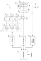
図2は、画像表示装置20の照射光生成部21の構成および照射光生成部21に用いる回路の構成を示す図である。 FIG. 2 is a diagram showing a configuration of an irradiation light generation unit 21 of the image display device 20 and a configuration of a circuit used for the irradiation light generation unit 21.

照射光生成部21は、光源101と、コリメータレンズ102a〜102cと、ミラー103と、ダイクロイックミラー104、105と、走査部106と、補正レンズ107と、可動スクリーン301と、固定スクリーン302と、駆動部300とを備える。 The irradiation light generation unit 21 drives the light source 101, the collimator lenses 102a to 102c, the mirror 103, the dichroic mirrors 104 and 105, the scanning unit 106, the correction lens 107, the movable screen 301, the fixed screen 302, and the like. A unit 300 is provided.

光源101は、3つのレーザ光源101a〜101cを備える。レーザ光源101a〜101cは、それぞれ、赤色波長帯、緑色波長帯および青色波長帯のレーザ光を出射する。本実施形態では、画像30としてカラー画像を表示するために、光源101が3つのレーザ光源101a〜101cを備えている。画像30として単色の画像を表示する場合、光源101は、画像の色に対応する1つのレーザ光源のみを備えていてもよい。レーザ光源101a〜101cは、たとえば、半導体レーザからなっている。 The light source 101 includes three laser light sources 101a to 101c. The laser light sources 101a to 101c emit laser light in the red wavelength band, the green wavelength band, and the blue wavelength band, respectively. In the present embodiment, the light source 101 includes three laser light sources 101a to 101c in order to display a color image as the image 30. When displaying a monochromatic image as the image 30, the light source 101 may include only one laser light source corresponding to the color of the image. The laser light sources 101a to 101c are made of, for example, a semiconductor laser.

レーザ光源101a〜101cから出射されたレーザ光は、それぞれ、コリメータレンズ102a〜102cによって略平行光に変換される。このとき、レーザ光源101a〜101cから出射されたレーザ光は、それぞれ、図示しないアパーチャによって、円形のビーム形状に整形される。なお、コリメータレンズ102a〜102cに代えて、レーザ光を円形のビーム形状に整形し且つ平行光化する整形レンズを用いてもよい。この場合、アパーチャは省略され得る。 The laser light emitted from the laser light sources 101a to 101c is converted into substantially parallel light by the collimator lenses 102a to 102c, respectively. At this time, the laser light emitted from the laser light sources 101a to 101c is shaped into a circular beam shape by an aperture (not shown). Instead of the collimator lenses 102a to 102c, a shaping lens that shapes the laser beam into a circular beam shape and makes it parallel light may be used. In this case, the aperture may be omitted.

その後、レーザ光源101a〜101cから出射された各色のレーザ光は、ミラー103と2つのダイクロイックミラー104、105によって光軸が整合される。ミラー103は、コリメータレンズ102aを透過した赤色レーザ光を略全反射する。ダイクロイックミラー104は、コリメータレンズ102bを透過した緑色レーザ光を反射し、ミラー103で反射された赤色レーザ光を透過する。ダイクロイックミラー105は、コリメータレンズ102cを透過した青レーザ光を反射し、ダイクロイックミラー104を経由した赤色レーザ光および緑色レーザ光を透過する。ミラー103と2つのダイクロイックミラー104、105は、レーザ光源101a〜101cから出射された各色のレーザ光の光軸を整合させるように配置されている。 After that, the optical axes of the laser beams of each color emitted from the laser light sources 101a to 101c are aligned by the mirror 103 and the two dichroic mirrors 104 and 105. The mirror 103 substantially totally reflects the red laser beam transmitted through the collimator lens 102a. The dichroic mirror 104 reflects the green laser light transmitted through the collimator lens 102b, and transmits the red laser light reflected by the mirror 103. The dichroic mirror 105 reflects the blue laser light that has passed through the collimator lens 102c, and transmits the red laser light and the green laser light that have passed through the dichroic mirror 104. The mirror 103 and the two dichroic mirrors 104 and 105 are arranged so as to align the optical axes of the laser beams of the respective colors emitted from the laser light sources 101a to 101c.

走査部106は、ダイクロイックミラー105を経由した各色のレーザ光を反射する。走査部106は、たとえば、MEMS(micro electro mechanical system)ミラーからなっており、ダイクロイックミラー105を経由した各色のレーザ光が入射されるミラー106aを、駆動信号に応じて、Y軸に平行な軸とX軸に平行な軸の周りに回転させる構成を備える。このようにミラー106aを回転させることにより、レーザ光の反射方向が、X−Z平面の面内方向およびY−Z平面の面内方向において変化する。これにより、後述のように、各色のレーザ光によって可動スクリーン301が走査される。 The scanning unit 106 reflects the laser light of each color via the dichroic mirror 105. The scanning unit 106 is composed of, for example, a MEMS (micro electro mechanical system) mirror, and is an axis parallel to the Y axis according to a drive signal of the mirror 106a on which laser light of each color is incident via the dichroic mirror 105. It has a configuration that rotates around an axis parallel to the X-axis. By rotating the mirror 106a in this way, the reflection direction of the laser beam changes in the in-plane direction of the XX plane and the in-plane direction of the YY plane. As a result, as will be described later, the movable screen 301 is scanned by the laser light of each color.

なお、ここでは、走査部106が、2軸駆動方式のMEMSミラーにより構成されたが、走査部106は、他の構成であってもよい。たとえば、Y軸に平行な軸の周りに回転駆動されるミラーと、X軸に平行な軸の周りに回転駆動されるミラーとを組み合わせて走査部106が構成されてもよい。 Although the scanning unit 106 is configured by the two-axis drive type MEMS mirror here, the scanning unit 106 may have another configuration. For example, the scanning unit 106 may be configured by combining a mirror that is rotationally driven around an axis parallel to the Y-axis and a mirror that is rotationally driven around an axis that is parallel to the X-axis.

補正レンズ107は、走査部106によるレーザ光の振り角に拘わらず、各色のレーザ光をZ軸正方向に向かわせるように設計されている。可動スクリーン301および固定スクリーン302は、それぞれ、レーザ光が走査されることにより画像が形成され、入射したレーザ光を運転者2の目2aの位置周辺の領域(アイボックス領域)に拡散させる作用を有する。 The correction lens 107 is designed so that the laser light of each color is directed in the positive direction of the Z axis regardless of the swing angle of the laser light by the scanning unit 106. Each of the movable screen 301 and the fixed screen 302 has an action of forming an image by scanning the laser beam and diffusing the incident laser beam into a region (eye box region) around the position of the driver 2's eye 2a. Have.

駆動部300は、可動スクリーン301をレーザ光の進行方向に平行な方向(Z軸方向)に往復移動させる。駆動部300の構成は、追って、図3〜図13を参照して説明する。固定スクリーン302は、駆動部300によって移動されない。固定スクリーン302は、駆動部300上の所定の位置に固定される。固定スクリーン302の配置については、追って、図10および図11を参照して説明する。 The drive unit 300 reciprocates the movable screen 301 in a direction parallel to the traveling direction of the laser beam (Z-axis direction). The configuration of the drive unit 300 will be described later with reference to FIGS. 3 to 13. The fixed screen 302 is not moved by the drive unit 300. The fixed screen 302 is fixed at a predetermined position on the drive unit 300. The arrangement of the fixed screen 302 will be described later with reference to FIGS. 10 and 11.

画像処理回路201は、CPU(Central Processing Unit)等の演算処理ユニットやメモリを備え、入力された映像信号を処理してレーザ駆動回路202、ミラー駆動回路203およびスクリーン駆動回路204を制御する。レーザ駆動回路202は、画像処理回路201からの制御信号に応じて、レーザ光源101a〜101cの出射強度を変化させる。ミラー駆動回路203は、画像処理回路201からの制御信号に応じて、走査部106のミラー106aを駆動する。スクリーン駆動回路204は、画像処理回路201からの制御信号に応じて、可動スクリーン301を駆動する。画像表示動作時における画像処理回路201における制御については、追って、図15(b)を参照して説明する。 The image processing circuit 201 includes an arithmetic processing unit such as a CPU (Central Processing Unit) and a memory, and processes the input video signal to control the laser drive circuit 202, the mirror drive circuit 203, and the screen drive circuit 204. The laser drive circuit 202 changes the emission intensity of the laser light sources 101a to 101c according to the control signal from the image processing circuit 201. The mirror drive circuit 203 drives the mirror 106a of the scanning unit 106 in response to a control signal from the image processing circuit 201. The screen drive circuit 204 drives the movable screen 301 in response to a control signal from the image processing circuit 201. The control in the image processing circuit 201 during the image display operation will be described later with reference to FIG. 15 (b).

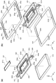
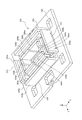
図3は、駆動部300の構成を示す斜視図である。なお、以下では、XYZ軸により方向を規定する他、便宜上、平面視において、駆動部300の中心に近い方を内側とし、駆動部300の中心から離れた方を外側として構成の説明を行う。 FIG. 3 is a perspective view showing the configuration of the drive unit 300. In addition to defining the direction by the XYZ axes, the configuration will be described below with the side closer to the center of the drive unit 300 as the inner side and the side away from the center of the drive unit 300 as the outer side in a plan view.

駆動部300は、ホルダ303と、カバー304と、2つのサスペンション305と、支持部材306と、ベース307と、ワッシャー308と、ネジ309と、磁気回路310とを備えている。可動スクリーン301は、ホルダ303に保持され、固定スクリーン302は、カバー304に保持されている。カバー304には、開口304aが形成され、この開口304aから可動スクリーン301が露出している。固定スクリーン302は、開口304aのY軸正側の部分に設置されている。 The drive unit 300 includes a holder 303, a cover 304, two suspensions 305, a support member 306, a base 307, a washer 308, a screw 309, and a magnetic circuit 310. The movable screen 301 is held by the holder 303, and the fixed screen 302 is held by the cover 304. An opening 304a is formed in the cover 304, and the movable screen 301 is exposed from the opening 304a. The fixed screen 302 is installed in a portion of the opening 304a on the positive side of the Y-axis.

ホルダ303は、サスペンション305によって、Z軸方向に移動可能に支持されている。支持部材306がベース307に設置され、この支持部材306に、サスペンション305がワッシャー308とネジ309により固定されている。さらに、ベース307には磁気回路310が設置されている。ホルダ303に保持されたコイル(図示せず)に磁気回路310から磁界が印加される。コイルに電流を流すことにより、ホルダ303がZ軸方向に駆動される。 The holder 303 is movably supported in the Z-axis direction by the suspension 305. A support member 306 is installed on the base 307, and a suspension 305 is fixed to the support member 306 by a washer 308 and a screw 309. Further, a magnetic circuit 310 is installed on the base 307. A magnetic field is applied from the magnetic circuit 310 to the coil (not shown) held in the holder 303. By passing an electric current through the coil, the holder 303 is driven in the Z-axis direction.

図4は、磁気回路310の構成を示す分解斜視図である。 FIG. 4 is an exploded perspective view showing the configuration of the magnetic circuit 310.

磁気回路310は、第1のヨーク311と、第1の磁石312a、312bと、第2のヨーク313と、第2の磁石314a、314bとを備えている。 The magnetic circuit 310 includes a first yoke 311 and a first magnet 312a and 312b, a second yoke 313, and a second magnet 314a and 314b.

ベース307は、平面視において略長方形の輪郭を有する。ベース307は、磁性体からなっている。ベース307には、開口307aと、4つの突起307bと、8つのボス307cと、9つのネジ穴307dが形成されている。開口307aは、図2に示す補正レンズ107からのレーザ光をZ軸正方向に通すためのものである。突起307bとボス307cは、ベース307上に設置される各部材を所定の位置に位置決めするためのものである。ネジ穴307dは、ベース307上に設置される各部材をネジで固定するためのものである。 The base 307 has a substantially rectangular contour in plan view. The base 307 is made of a magnetic material. The base 307 is formed with openings 307a, four protrusions 307b, eight bosses 307c, and nine screw holes 307d. The opening 307a is for passing the laser beam from the correction lens 107 shown in FIG. 2 in the positive direction of the Z axis. The protrusions 307b and the bosses 307c are for positioning each member installed on the base 307 in a predetermined position. The screw hole 307d is for fixing each member installed on the base 307 with a screw.

第1のヨーク311は、外側の壁部311aと内側の壁部311bとを備える。壁部311a、311bの互いに向き合う内側面に、それぞれ、第1の磁石312a、312bが装着される。また、第2のヨーク313は、外側の壁部313aと内側の壁部313bとを備える。壁部313a、313bの互いに向き合う内側面に、それぞれ、第2の磁石314a、314bが装着される。 The first yoke 311 includes an outer wall portion 311a and an inner wall portion 311b. The first magnets 312a and 312b are mounted on the inner surfaces of the wall portions 311a and 311b facing each other, respectively. Further, the second yoke 313 includes an outer wall portion 313a and an inner wall portion 313b. Second magnets 314a and 314b are mounted on the inner surfaces of the wall portions 313a and 313b facing each other, respectively.

図5(a)〜(c)は、それぞれ、第1のヨーク311および第1の磁石312a、312bの構成を示す正面図、側面図および平面図である。また、図5(d)〜(f)は、それぞれ、第2のヨーク313および第2の磁石314a、314bの構成を示す正面図、側面図および平面図である。 5 (a) to 5 (c) are a front view, a side view, and a plan view showing the configurations of the first yoke 311 and the first magnets 312a and 312b, respectively. 5 (d) to 5 (f) are a front view, a side view, and a plan view showing the configurations of the second yoke 313 and the second magnets 314a and 314b, respectively.

なお、図5(a)〜(c)には、図4のX軸正側の第1のヨーク311と第1の磁石312a、312bの組み合わせが、XYZ軸とともに図示されている。また、図5(d)〜(f)には、図4のY軸負側の第2のヨーク313と第2の磁石314a、314bの組み合わせが、XYZ軸とともに図示されている。図4のX軸負側の第1のヨーク311と第1の磁石312a、312bの組み合わせおよびY軸正側の第2のヨーク313と第2の磁石314a、314bの組み合わせも、図5(a)〜(c)の構成および図5(d)〜(f)の構成と同様である。 In addition, in FIGS. 5A to 5C, the combination of the first yoke 311 on the positive side of the X-axis and the first magnets 312a and 312b in FIG. 4 is shown together with the XYZ axes. Further, in FIGS. 5 (d) to 5 (f), the combination of the second yoke 313 on the negative side of the Y axis and the second magnets 314a and 314b in FIG. 4 is shown together with the XYZ axes. The combination of the first yoke 311 on the negative side of the X axis and the first magnets 312a and 312b in FIG. 4 and the combination of the second yoke 313 and the second magnets 314a and 314b on the positive side of the Y axis are also shown in FIG. 5 (a). )-(C) and FIGS. 5 (d)-(f) are the same.

図5(a)〜(c)を参照して、第1のヨーク311は、Y軸方向からの側面視において、略U字の形状を有する。すなわち、Y軸方向の中央位置で第1のヨーク311を切断した断面は、略U字状である。第1のヨーク311は、たとえば、平板の展開状態から壁部311a、311bの部分を折り曲げることにより形成される。第1のヨーク311は、Y軸方向に対称な形状である。 With reference to FIGS. 5 (a) to 5 (c), the first yoke 311 has a substantially U-shape when viewed from the side in the Y-axis direction. That is, the cross section of the first yoke 311 cut at the center position in the Y-axis direction is substantially U-shaped. The first yoke 311 is formed, for example, by bending the wall portions 311a and 311b from the unfolded state of the flat plate. The first yoke 311 has a shape symmetrical in the Y-axis direction.

図5(c)に示すように、壁部311aは、幅方向(Y軸方向)に分離されており、分離された壁部311aにそれぞれ第1の磁石312aが設置されている。同様に、壁部311bも、幅方向(Y軸方向)に分離され、分離された壁部311aにそれぞれ第1の磁石312aが設置されている。したがって、2つの壁部311aの間には隙間311cがあり、また、2つの壁部311bの間にも隙間311dがある。 As shown in FIG. 5C, the wall portion 311a is separated in the width direction (Y-axis direction), and the first magnet 312a is installed in each of the separated wall portions 311a. Similarly, the wall portion 311b is also separated in the width direction (Y-axis direction), and the first magnet 312a is installed on each of the separated wall portions 311a. Therefore, there is a gap 311c between the two wall portions 311a, and there is also a gap 311d between the two wall portions 311b.

X軸方向に見たときの第1の磁石312a、312bの輪郭は、方形形状である。第1の磁石312aは、第1の磁石312bよりもY軸方向の幅が広い。Z軸方向における第1の磁石312aと第1の磁石312bの幅は、互いに同じである。図5(c)に示すように、第1の磁石312aのY軸方向の幅は、壁部311aのY軸方向の幅よりも狭く、第1の磁石312bのY軸方向の幅は、壁部311bのY軸方向の幅よりも広い。第1のヨーク311の底部には、ネジ止めのための孔311eが形成されている。 The contours of the first magnets 312a and 312b when viewed in the X-axis direction are square. The first magnet 312a is wider in the Y-axis direction than the first magnet 312b. The widths of the first magnet 312a and the first magnet 312b in the Z-axis direction are the same as each other. As shown in FIG. 5C, the width of the first magnet 312a in the Y-axis direction is narrower than the width of the wall portion 311a in the Y-axis direction, and the width of the first magnet 312b in the Y-axis direction is the wall. It is wider than the width of the portion 311b in the Y-axis direction. A hole 311e for screwing is formed at the bottom of the first yoke 311.

図5(d)〜(f)を参照して、第2のヨーク313は、X軸方向からの側面視において、略U字の形状を有する。すなわち、X軸方向の中央位置で第2のヨーク313を切断した断面は、略U字状である。第2のヨーク313は、たとえば、平板の展開状態から壁部313a、313bの部分を折り曲げることにより形成される。第2のヨーク313は、X軸方向に対称な形状である。 With reference to FIGS. 5 (d) to 5 (f), the second yoke 313 has a substantially U-shape when viewed from the side in the X-axis direction. That is, the cross section of the second yoke 313 cut at the center position in the X-axis direction is substantially U-shaped. The second yoke 313 is formed, for example, by bending the wall portions 313a and 313b from the unfolded state of the flat plate. The second yoke 313 has a shape symmetrical in the X-axis direction.

Y軸方向に見たときの第2の磁石314a、314bの輪郭は、方形形状である。第2の磁石314aは、第2の磁石314bよりもX軸方向の幅が広い。Z軸方向における第2の磁石314aと第2の磁石314bの幅は、互いに同じである。図5(f)に示すように、第2の磁石314aのX軸方向の幅は、壁部313aのX軸方向の幅よりも狭く、第2の磁石314bのX軸方向の幅は、壁部313bのX軸方向の幅と同じである。第2のヨーク313の底部には、ネジ止めのための2つの孔313cが形成されている。 The contours of the second magnets 314a and 314b when viewed in the Y-axis direction are square. The second magnet 314a is wider in the X-axis direction than the second magnet 314b. The widths of the second magnet 314a and the second magnet 314b in the Z-axis direction are the same as each other. As shown in FIG. 5 (f), the width of the second magnet 314a in the X-axis direction is narrower than the width of the wall portion 313a in the X-axis direction, and the width of the second magnet 314b in the X-axis direction is the wall. It is the same as the width of the portion 313b in the X-axis direction. At the bottom of the second yoke 313, two holes 313c for screwing are formed.

図4に戻り、このように第1の磁石312a、312bが設置された状態で、X軸正側の第1のヨーク311が、ベース307の開口307aのX軸正側に設置され、X軸負側の第1のヨーク311が、ベース307の開口307aのX軸負側に設置される。また、第2の磁石314a、314bが設置された状態で、Y軸正側の第2のヨーク313が、ベース307の開口307aのY軸正側に設置され、Y軸負側の第2のヨーク313が、ベース307の開口307aのY軸負側に設置される。こうして、図6に示すように、磁気回路310がベース307上に設置される。 Returning to FIG. 4, with the first magnets 312a and 312b installed in this way, the first yoke 311 on the positive side of the X-axis is installed on the positive side of the X-axis of the opening 307a of the base 307, and the X-axis The negative first yoke 311 is installed on the negative side of the X-axis of the opening 307a of the base 307. Further, with the second magnets 314a and 314b installed, the second yoke 313 on the positive side of the Y axis is installed on the positive side of the Y axis of the opening 307a of the base 307, and the second yoke on the negative side of the Y axis is installed. The yoke 313 is installed on the negative side of the Y-axis of the opening 307a of the base 307. Thus, as shown in FIG. 6, the magnetic circuit 310 is installed on the base 307.

たとえば、第1の磁石312a、312bは、内側の第1の磁石312bから外側の第1の磁石312aへと磁界が向かうように磁極が調整され、また、第2の磁石314a、314bは、内側の第2の磁石314bから外側の第2の磁石314aへと磁界が向かうように磁極が調整されている。 For example, the magnetic poles of the first magnets 312a and 312b are adjusted so that the magnetic field is directed from the inner first magnet 312b to the outer first magnet 312a, and the second magnets 314a and 314b are inside. The magnetic poles are adjusted so that the magnetic field is directed from the second magnet 314b of the above to the outer second magnet 314a.

図7(a)は、ホルダ303、可動スクリーン301およびコイル315の組立て過程を示す斜視図である。 FIG. 7A is a perspective view showing an assembly process of the holder 303, the movable screen 301, and the coil 315.

ホルダ303は、樹脂等の比重が小さい材料で一体形成されている。ホルダ303は、X軸方向に対称な形状を有し、且つ、Y軸方向に対称な形状を有している。ホルダ303は、可動スクリーン301が設置される略長方形の内枠303aと、コイル315が設置される略長方形の外枠303bとを備えている。内枠303aは、橋部303cによって外枠303bに接続されている。橋部303cは、内枠303aのY軸方向の中央位置と、外枠303bのY軸方向の中央位置とを繋いでいる。さらに、外枠303bのY軸方向の中央位置に、2つの被支持部303dが、X軸方向に延びるように形成されている。 The holder 303 is integrally formed of a material having a small specific gravity such as resin. The holder 303 has a shape symmetrical in the X-axis direction and a shape symmetrical in the Y-axis direction. The holder 303 includes a substantially rectangular inner frame 303a in which the movable screen 301 is installed, and a substantially rectangular outer frame 303b in which the coil 315 is installed. The inner frame 303a is connected to the outer frame 303b by the bridge portion 303c. The bridge portion 303c connects the central position of the inner frame 303a in the Y-axis direction and the central position of the outer frame 303b in the Y-axis direction. Further, at the center position of the outer frame 303b in the Y-axis direction, two supported portions 303d are formed so as to extend in the X-axis direction.

機械的強度を保ちつつ軽量化を図るため、ホルダ303の内枠303aと被支持部303dには、種々の抜き孔303eが形成されている。また、内枠303aには、レーザ光を通すための開口303fが設けられている。開口303fは、平面視において略長方形の輪郭を有する。開口303fの周囲に段差が設けられている。この段差に、可動スクリーン301の端縁301aが嵌め込まれて、可動スクリーン301がホルダ303の内枠303aに装着される。可動スクリーン301は、接着剤により内枠303aに固定される。 In order to reduce the weight while maintaining the mechanical strength, various punch holes 303e are formed in the inner frame 303a and the supported portion 303d of the holder 303. Further, the inner frame 303a is provided with an opening 303f for passing laser light. The opening 303f has a substantially rectangular contour in a plan view. A step is provided around the opening 303f. The edge 301a of the movable screen 301 is fitted into this step, and the movable screen 301 is attached to the inner frame 303a of the holder 303. The movable screen 301 is fixed to the inner frame 303a by an adhesive.

また、外枠303bの4つの角部分には、それぞれ、Z軸負側に突出する円柱状の突起303gが形成されている。これら突起303gにコイル315の内側が嵌め込まれて、コイル315がホルダ303の外枠303bに装着される。コイル315は、接着剤により外枠303bに固定される。コイル315は、Z軸に平行な軸の周りを一方向に回るように構成されている。被支持部303dの上面および下面には、Z軸方向に並ぶ位置に、それぞれ、突部303hが形成されている。さらに、被支持部303dのX軸正側またはX軸負側の側面に、それぞれスケール303iが設置されている。 Further, each of the four corner portions of the outer frame 303b is formed with a columnar protrusion 303g projecting on the negative side of the Z axis. The inside of the coil 315 is fitted into these protrusions 303g, and the coil 315 is mounted on the outer frame 303b of the holder 303. The coil 315 is fixed to the outer frame 303b with an adhesive. The coil 315 is configured to rotate in one direction around an axis parallel to the Z axis. Protrusions 303h are formed on the upper surface and the lower surface of the supported portion 303d at positions aligned in the Z-axis direction, respectively. Further, scales 303i are installed on the side surfaces of the supported portion 303d on the positive side of the X-axis or the negative side of the X-axis, respectively.

図7(b)は、ホルダ303およびサスペンション305の組立て過程を示す斜視図である。図7(b)の上側のサスペンション305と下側のサスペンション305は、同じ構造である。下側のサスペンション305と、上側のサスペンション305は、互いに表裏反転された関係にある。ここでは、便宜上、上側のサスペンション305について、構造の説明を行う。 FIG. 7B is a perspective view showing an assembly process of the holder 303 and the suspension 305. The upper suspension 305 and the lower suspension 305 in FIG. 7B have the same structure. The lower suspension 305 and the upper suspension 305 are in an inverted relationship with each other. Here, for convenience, the structure of the upper suspension 305 will be described.

サスペンション305は、可撓性のある金属材料で一体形成されている。サスペンション305は、薄板状のリング形状を有する。サスペンション305の形状は、X軸方向に対称で、且つ、Y軸方向にも対称である。サスペンション305は、開口305aと、X軸方向に延びる一対の板バネ部305bと、Y軸方向に延びる一対の梁部305cとを有する。 The suspension 305 is integrally formed of a flexible metal material. The suspension 305 has a thin plate-like ring shape. The shape of the suspension 305 is symmetrical in the X-axis direction and also in the Y-axis direction. The suspension 305 has an opening 305a, a pair of leaf spring portions 305b extending in the X-axis direction, and a pair of beam portions 305c extending in the Y-axis direction.

板バネ部305bのX軸方向の中央位置、すなわち、X軸方向の対称軸の位置に、Y軸方向に突出する鍔部305dが形成されている。また、板バネ部305bのX軸方向の中央位置には、2つの孔305eと円弧状の切欠き305fが形成されている。板バネ部305bは、X軸方向の中央位置からX軸方向の両端に向かうに従って、Y軸方向の幅が徐々に小さくなっている。これにより、板バネ部305bのバネ定数を保ちながら、板バネ部305bの可動端部の軽量化が図られている。 A flange portion 305d protruding in the Y-axis direction is formed at the center position of the leaf spring portion 305b in the X-axis direction, that is, at a position on the axis of symmetry in the X-axis direction. Further, two holes 305e and an arc-shaped notch 305f are formed at the center position of the leaf spring portion 305b in the X-axis direction. The width of the leaf spring portion 305b gradually decreases in the Y-axis direction from the central position in the X-axis direction toward both ends in the X-axis direction. As a result, the weight of the movable end of the leaf spring portion 305b is reduced while maintaining the spring constant of the leaf spring portion 305b.

梁部305cは、Y軸方向の中央位置、すなわち、Y軸方向の対称軸の位置に、X軸方向に突出する鍔部305gが形成されている。また、梁部305cのY軸方向の中央位置には、孔305hが形成されている。梁部305cは、Y軸方向の両端からY軸方向の中央位置に向かうに従って、X軸方向の幅が徐々に小さくなっている。これにより、梁部305cの軽量化が図られている。さらに、梁部305cの外側の端縁と内側の端縁に沿って、Z軸正方向に立ち上げられたリブ部305i、305jが形成されている。これらリブ部305i、305jにより、梁部305cがZ軸方向に撓むことが抑制されている。撓みを抑制することにより、意図しない周波数で振動することを抑制し、意図しない振動が発生した場合においても振幅を小さくすることができる。 The beam portion 305c has a flange portion 305g protruding in the X-axis direction formed at a central position in the Y-axis direction, that is, a position on the axis of symmetry in the Y-axis direction. Further, a hole 305h is formed at the center position of the beam portion 305c in the Y-axis direction. The width of the beam portion 305c gradually decreases in the X-axis direction from both ends in the Y-axis direction toward the center position in the Y-axis direction. As a result, the weight of the beam portion 305c is reduced. Further, rib portions 305i and 305j raised in the positive direction of the Z axis are formed along the outer edge and the inner edge of the beam portion 305c. These rib portions 305i and 305j prevent the beam portion 305c from bending in the Z-axis direction. By suppressing the deflection, it is possible to suppress vibration at an unintended frequency and reduce the amplitude even when unintended vibration occurs.

上側のサスペンション305は、ホルダ303の被支持部303dの上面に形成された突部303hがサスペンション305の孔305hに嵌め込まれて、ホルダ303に装着される。同様に、下側のサスペンション305は、ホルダ303の被支持部303dの下面に形成された突部303hがサスペンション305の孔305hに嵌め込まれて、ホルダ303に装着される。これらサスペンション305は、接着剤により、ホルダ303の被支持部303dに固着される。 The upper suspension 305 is mounted on the holder 303 by fitting the protrusion 303h formed on the upper surface of the supported portion 303d of the holder 303 into the hole 305h of the suspension 305. Similarly, in the lower suspension 305, the protrusion 303h formed on the lower surface of the supported portion 303d of the holder 303 is fitted into the hole 305h of the suspension 305 and mounted on the holder 303. These suspensions 305 are fixed to the supported portion 303d of the holder 303 by an adhesive.

図8は、サスペンション305と支持部材306の組立て過程を示す斜視図である。 FIG. 8 is a perspective view showing an assembly process of the suspension 305 and the support member 306.

支持部材306は、樹脂等の非磁性材料により形成されている。支持部材306は、Y軸方向に対称な形状を有する。平面視において、支持部材306の形状は、C字状である。支持部材306の両端には、それぞれ、X軸方向に延びた後、Y軸方向に屈曲する腕部306aが形成されている。腕部306a端部の上面および下面には、それぞれ、円柱状の突部306bと、半円柱状の突部306cと、ネジ穴306dがY軸方向に並んで形成されている。さらに、支持部材306の内側面には、Y軸方向の中央位置に、エンコーダ306eが設置されている。また、支持部材306の上面には、支持部材306をベース307に位置決めするための2つの穴とネジ止めするための3つの穴306fが形成されている。 The support member 306 is made of a non-magnetic material such as resin. The support member 306 has a shape symmetrical in the Y-axis direction. In a plan view, the shape of the support member 306 is C-shaped. At both ends of the support member 306, arm portions 306a that extend in the X-axis direction and then bend in the Y-axis direction are formed. A columnar protrusion 306b, a semi-cylindrical protrusion 306c, and a screw hole 306d are formed side by side in the Y-axis direction on the upper surface and the lower surface of the end portion of the arm portion 306a, respectively. Further, an encoder 306e is installed on the inner surface of the support member 306 at a central position in the Y-axis direction. Further, on the upper surface of the support member 306, two holes for positioning the support member 306 on the base 307 and three holes 306f for screwing the support member 306 are formed.

上側のサスペンション305を支持部材306に装着する場合、腕部306a上面の突部306b、306cが、それぞれ、サスペンション305の外側の孔305eと切欠き305fに嵌められる。この状態で、サスペンション305の内側の孔305eと腕部306a上面のネジ穴306dとが整合する。この状態で、ワッシャー308を介してネジ309が、サスペンション305の内側の孔305eに通されて、ネジ穴306dに留められる。これにより、上側のサスペンション305が支持部材306に固定される。下側のサスペンション305も、同様にして、腕部306aの下面にネジ止めされる。こうして、2つのサスペンション305が、支持部材306に固定される。 When the upper suspension 305 is attached to the support member 306, the protrusions 306b and 306c on the upper surface of the arm 306a are fitted into the outer holes 305e and the notch 305f of the suspension 305, respectively. In this state, the inner hole 305e of the suspension 305 and the screw hole 306d on the upper surface of the arm 306a are aligned. In this state, the screw 309 is passed through the hole 305e inside the suspension 305 via the washer 308 and fastened to the screw hole 306d. As a result, the upper suspension 305 is fixed to the support member 306. The lower suspension 305 is also screwed to the lower surface of the arm 306a in the same manner. In this way, the two suspensions 305 are fixed to the support member 306.

こうして、2つのサスペンション305が、支持部材306に固定されると、支持部材306のエンコーダ306eが、ホルダ303のX軸負側の被支持部303dの側面に設置されたスケール303i(図7(a)参照)と対向する。エンコーダ306eは、Z軸方向におけるスケール303iの移動を光学的に検出するためのものである。エンコーダ306eからの検出信号に基づいて、ホルダ303および可動スクリーン301のZ軸方向の位置が検出される。 When the two suspensions 305 are fixed to the support member 306 in this way, the encoder 306e of the support member 306 is installed on the side surface of the supported portion 303d on the negative side of the X-axis of the holder 303 (FIG. 7 (a). ) Opposite. The encoder 306e is for optically detecting the movement of the scale 303i in the Z-axis direction. Based on the detection signal from the encoder 306e, the positions of the holder 303 and the movable screen 301 in the Z-axis direction are detected.

図9は、支持部材306とベース307の組立て過程を示す斜視図である。 FIG. 9 is a perspective view showing an assembly process of the support member 306 and the base 307.

支持部材306は、穴306fがベース307のネジ穴307dの位置に整合するようにベース307上に位置づけられる。このとき、ホルダ303の外枠303bに装着されたコイル315が、第1の磁石312a、312bの間の隙間および第2の磁石314a、314bの間の隙間に挿入される。また、橋部303cが第1のヨーク311の隙間311dに挿入され、被支持部303dが第1のヨーク311の隙間311cに挿入される。これにより、ホルダ303および可動スクリーン301は、磁気回路310の上面よりも低い位置に位置づけられる。この状態で、穴306fを介してネジがベース307のネジ穴307dにネジ止めされる。これにより、支持部材306がベース307に固定される。 The support member 306 is positioned on the base 307 so that the holes 306f are aligned with the positions of the screw holes 307d of the base 307. At this time, the coil 315 mounted on the outer frame 303b of the holder 303 is inserted into the gap between the first magnets 312a and 312b and the gap between the second magnets 314a and 314b. Further, the bridge portion 303c is inserted into the gap 311d of the first yoke 311, and the supported portion 303d is inserted into the gap 311c of the first yoke 311. As a result, the holder 303 and the movable screen 301 are positioned lower than the upper surface of the magnetic circuit 310. In this state, the screw is screwed into the screw hole 307d of the base 307 through the hole 306f. As a result, the support member 306 is fixed to the base 307.

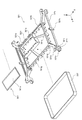
図10は、カバー304および固定スクリーン302の組立て過程を示す斜視図である。 FIG. 10 is a perspective view showing an assembly process of the cover 304 and the fixed screen 302.

カバー304は、磁性体からなっている。カバー304は、X軸方向に対称な形状である。カバー304には、レーザ光を通すための開口304aが形成されている。開口304aは、Y軸正側の部分のX軸方向の幅がその他の部分よりも小さくなっている。固定スクリーン302は、端縁302aが開口304aのY軸正側の部分に嵌め込まれるようにして、開口304aのY軸正側の部分に装着される。固定スクリーン302は、接着剤により、カバー304の下面に固定される。 The cover 304 is made of a magnetic material. The cover 304 has a shape symmetrical in the X-axis direction. The cover 304 is formed with an opening 304a for passing laser light. The width of the portion of the opening 304a on the positive side of the Y-axis in the X-axis direction is smaller than that of the other portions. The fixed screen 302 is attached to the Y-axis positive side portion of the opening 304a so that the edge 302a is fitted into the Y-axis positive side portion of the opening 304a. The fixing screen 302 is fixed to the lower surface of the cover 304 by an adhesive.

こうして固定スクリーン302が装着された状態で、カバー304が磁気回路310の上面に重ねられる。カバー304は、磁性体からなっているため、磁気回路310の磁力により、磁気回路310を構成する第1のヨーク311と第2のヨーク313の上面に吸着される。これにより、カバー304の取り付けが完了し、図3に示す駆動部300が構成される。 With the fixed screen 302 mounted in this way, the cover 304 is superposed on the upper surface of the magnetic circuit 310. Since the cover 304 is made of a magnetic material, it is attracted to the upper surfaces of the first yoke 311 and the second yoke 313 constituting the magnetic circuit 310 by the magnetic force of the magnetic circuit 310. As a result, the attachment of the cover 304 is completed, and the drive unit 300 shown in FIG. 3 is configured.

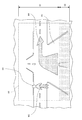
図11は、駆動部300の構成を示す平面図である。図12は、カバー304を透視した状態の駆動部300の構成を示す平面図である。 FIG. 11 is a plan view showing the configuration of the drive unit 300. FIG. 12 is a plan view showing the configuration of the drive unit 300 in a state where the cover 304 is seen through.

図11および図12に示すように、可動スクリーン301と固定スクリーン302は、Y軸方向に並ぶように配置されている。内枠303aの開口303fは、3分の2程度の領域が、可動スクリーン301によって覆われ、残り3分の1程度の領域が開放されている。開口303fの開放された領域が、固定スクリーン302によって覆われている。Z軸負側から入射したレーザ光は、可動スクリーン301を走査した後、固定スクリーン302を走査する。 As shown in FIGS. 11 and 12, the movable screen 301 and the fixed screen 302 are arranged so as to be arranged in the Y-axis direction. About two-thirds of the opening 303f of the inner frame 303a is covered with the movable screen 301, and the remaining one-third is open. The open area of the opening 303f is covered by the fixed screen 302. The laser beam incident from the negative side of the Z axis scans the movable screen 301 and then the fixed screen 302.

図13は、磁気回路310とサスペンション305の部分の平面図である。便宜上、図13には、コイル315が破線で示されているが、実際には、コイル315は、外枠303bのZ軸負側に配置されている。 FIG. 13 is a plan view of a portion of the magnetic circuit 310 and the suspension 305. For convenience, the coil 315 is shown by a broken line in FIG. 13, but in reality, the coil 315 is arranged on the negative side of the Z-axis of the outer frame 303b.

破線の丸の領域A1に示すように、第1のヨーク311の内側の壁部311bの側端面と第2のヨーク313の内側の壁部313bの外側面とが互いに重なりあうように、第1のヨーク311と第2のヨーク313が配置されている。また、この重なり部分において、第1のヨーク311の内側の壁部311bに設置された第1の磁石312bが、第2のヨーク313の内側の壁部313bの側端面まで延びている。この構成により、より効率的に、コイル315に磁界を印加することができる。 As shown in the dashed circle area A1, the first side end surface of the inner wall portion 311b of the first yoke 311 and the outer surface of the inner wall portion 313b of the second yoke 313 overlap each other. The yoke 311 and the second yoke 313 are arranged. Further, in this overlapping portion, the first magnet 312b installed on the inner wall portion 311b of the first yoke 311 extends to the side end surface of the inner wall portion 313b of the second yoke 313. With this configuration, a magnetic field can be applied to the coil 315 more efficiently.

すなわち、このように壁部311bと壁部313bとを重ねることにより、第2のヨーク313の内側の壁部313bをコイル315の角付近まで延ばすことができ、且つ、第1の磁石312bをコイル315の角付近まで延ばすことができる。これにより、コイル315の角付近まで磁界を印加できる。さらに、本実施形態では、第1の磁石312aがコイル315の角付近まで延ばされており、また、第2の磁石314aがコイル315の角付近まで延ばされている。これにより、コイル315の角付近まで磁界を印加できる。 That is, by overlapping the wall portion 311b and the wall portion 313b in this way, the inner wall portion 313b of the second yoke 313 can be extended to the vicinity of the corner of the coil 315, and the first magnet 312b can be coiled. It can be extended to near the corner of 315. As a result, a magnetic field can be applied up to the vicinity of the corner of the coil 315. Further, in the present embodiment, the first magnet 312a is extended to the vicinity of the corner of the coil 315, and the second magnet 314a is extended to the vicinity of the corner of the coil 315. As a result, a magnetic field can be applied up to the vicinity of the corner of the coil 315.

このように、コイル315に効率的に磁界が印加されることにより、コイル315に生じる駆動力(ローレンツ力)が高められる。これにより、ホルダ303および可動スクリーン301を迅速に移動させ得る。 By efficiently applying the magnetic field to the coil 315 in this way, the driving force (Lorentz force) generated in the coil 315 is increased. As a result, the holder 303 and the movable screen 301 can be moved quickly.

また、図13に示すように、板バネ部305bは、可動スクリーン301の長辺に略平行に配置され、長手方向の中央位置においてベース307側に固定され、両端が梁部305cを介してホルダ303に接続されている。このように、板バネ部305bを可動スクリーン301の長辺に略平行に配置することにより、駆動部300をコンパクトに収めながら、板バネ部305bの固定位置P1から両端までの距離L1を長く確保できる。これにより、ホルダ303の駆動時に生じる板バネ部305bの応力が低減され、ホルダ303駆動時の負荷が軽減される。よって、板バネ部305bの変形を防止し耐久性を高めることができる。 Further, as shown in FIG. 13, the leaf spring portion 305b is arranged substantially parallel to the long side of the movable screen 301, is fixed to the base 307 side at the central position in the longitudinal direction, and both ends are holders via the beam portion 305c. It is connected to 303. By arranging the leaf spring portion 305b substantially parallel to the long side of the movable screen 301 in this way, the drive portion 300 is compactly housed, and the distance L1 from the fixed position P1 of the leaf spring portion 305b to both ends is secured long. can. As a result, the stress of the leaf spring portion 305b generated when the holder 303 is driven is reduced, and the load when the holder 303 is driven is reduced. Therefore, it is possible to prevent the leaf spring portion 305b from being deformed and improve the durability.

図14は、可動スクリーン301および固定スクリーン302に対するレーザ光の走査方法を模式的に示す図である。 FIG. 14 is a diagram schematically showing a method of scanning laser light with respect to the movable screen 301 and the fixed screen 302.

可動スクリーン301は、各色のレーザ光が重ねられたビームB1によって、X軸正方向に走査される。可動スクリーン301に対して、予め、ビームB1が通る走査ラインL11〜L1nが、Y軸方向に一定間隔で設定されている。走査ラインL11〜L1nの開始位置と終了位置は、X軸方向において一致している。したがって、走査ラインL11〜L1nを囲む領域は長方形である。 The movable screen 301 is scanned in the positive direction of the X-axis by the beam B1 on which the laser beams of each color are superimposed. Scanning lines L11 to L1n through which the beam B1 passes are set in advance with respect to the movable screen 301 at regular intervals in the Y-axis direction. The start position and end position of the scanning lines L11 to L1n coincide with each other in the X-axis direction. Therefore, the area surrounding the scanning lines L11 to L1n is rectangular.

こうして、可動スクリーン301が走査された後、可動スクリーン301のY軸負側に配置された固定スクリーン302がビームB1によってX軸正方向に走査される。固定スクリーン302にも、予め、ビームB1が通る走査ラインL21〜L2mが、Y軸方向に一定間隔で設定されている。走査ラインL21〜L2mの開始位置と終了位置は、X軸方向において一致している。したがって、走査ラインL21〜L2mを囲む領域は長方形である。 In this way, after the movable screen 301 is scanned, the fixed screen 302 arranged on the negative side of the Y axis of the movable screen 301 is scanned by the beam B1 in the positive direction of the X axis. Scanning lines L21 to L2m through which the beam B1 passes are set in advance on the fixed screen 302 at regular intervals in the Y-axis direction. The start position and end position of the scanning lines L21 to L2m coincide with each other in the X-axis direction. Therefore, the area surrounding the scanning lines L21 to L2m is rectangular.

映像信号により各色のレーザ光が変調されたビームB1により走査ラインL11〜L1nと走査ラインL21〜L2mが高周波で走査されることにより、画像が構成される。こうして構成された画像が、可動スクリーン301および固定スクリーン302と、ミラー22およびウインドシールド12(図1(c)参照)を介して、運転者2の目2aの位置周辺の領域(アイボックス)に投射される。これにより、運転者2は、ウインドシールド12の前方の空間に、虚像として画像30を視認する。 An image is formed by scanning scanning lines L11 to L1n and scanning lines L21 to L2m at high frequencies by a beam B1 in which laser light of each color is modulated by a video signal. The image thus constructed passes through the movable screen 301 and the fixed screen 302, the mirror 22 and the windshield 12 (see FIG. 1C) in the area (eye box) around the position of the driver 2's eye 2a. Be projected. As a result, the driver 2 visually recognizes the image 30 as a virtual image in the space in front of the windshield 12.

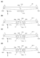
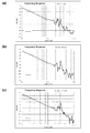
図15(a)、(b)は、それぞれ、可動スクリーン301の移動範囲D1を模式的に示す図、および、可動スクリーン301の駆動例を示すグラフである。 15 (a) and 15 (b) are a diagram schematically showing a moving range D1 of the movable screen 301 and a graph showing a driving example of the movable screen 301, respectively.

図15(a)に示すように、本実施形態では、固定スクリーン302が可動スクリーン301に対してZ軸正側およびY軸正側に変位した位置に固定されている。すなわち、固定スクリーン302は、可動スクリーン301よりも、光源101から光学的に離れた位置に配置され、可動スクリーン301の短辺に平行な方向に、可動スクリーン301から離れた位置に配置されている。 As shown in FIG. 15A, in the present embodiment, the fixed screen 302 is fixed at positions displaced on the Z-axis positive side and the Y-axis positive side with respect to the movable screen 301. That is, the fixed screen 302 is arranged at a position optically distant from the light source 101 from the movable screen 301, and is arranged at a position distant from the movable screen 301 in a direction parallel to the short side of the movable screen 301. ..

ここで、虚像として生成される画像30は、可動スクリーン301がZ軸負側(光源101側)にあるほど運転者の視点(目2aの位置)から遠い位置に生成される。固定スクリーン302は可動スクリーン301よりもZ軸正側にあるため、固定スクリーン302による画像は、可動スクリーン301による画像よりも、運転者の視点に近い位置に生成される。また、固定スクリーン302は、移動されないため、固定スクリーン302による画像は、常に、運転者の視点から一定の距離の位置に生成される。 Here, the image 30 generated as a virtual image is generated at a position farther from the driver's viewpoint (the position of the eyes 2a) as the movable screen 301 is closer to the negative side of the Z axis (the light source 101 side). Since the fixed screen 302 is on the positive side of the Z axis with respect to the movable screen 301, the image by the fixed screen 302 is generated at a position closer to the driver's viewpoint than the image by the movable screen 301. Further, since the fixed screen 302 is not moved, the image by the fixed screen 302 is always generated at a position at a certain distance from the driver's viewpoint.

図16は、可動スクリーン301と固定スクリーン302によって生成された画像の表示例を模式的に示す図である。 FIG. 16 is a diagram schematically showing a display example of an image generated by the movable screen 301 and the fixed screen 302.

図16の表示例において、奥行き画像M1は、ナビゲーション機能により乗用車1が道路R1を曲がるべき方向を運転者2に示唆するための矢印であり、鉛直画像M2は、歩行者H1が居ることを運転者2に注意喚起するためのマーキングである。たとえば、奥行き画像M1と鉛直画像M2は、互いに異なる色で表示される。可動スクリーン301と固定スクリーン302によって生成された画像が表示される領域S0は、上側の領域S1と下側の領域S2に区分される。上側の領域S1には、可動スクリーン301によって生成された画像が表示され、下側の領域S2には、固定スクリーン302によって生成された画像が表示される。 In the display example of FIG. 16, the depth image M1 is an arrow for suggesting to the driver 2 the direction in which the passenger car 1 should turn the road R1 by the navigation function, and the vertical image M2 is driving that the pedestrian H1 is present. This is a marking to call attention to person 2. For example, the depth image M1 and the vertical image M2 are displayed in different colors. The area S0 on which the image generated by the movable screen 301 and the fixed screen 302 is displayed is divided into an upper area S1 and a lower area S2. The image generated by the movable screen 301 is displayed in the upper area S1, and the image generated by the fixed screen 302 is displayed in the lower area S2.

図16に示すように、領域S1には、奥行き画像M1や鉛直画像M2等、運転に応じて動的に変化する画像が表示される。領域S2には、車速や外気温等の静的な画像が表示される。上記のように、領域S2には、固定スクリーン302によって生成された画像が表示され、この画像は、運転者の視点(目の位置)からの距離が短い位置(たとえば、2m程度の位置)に表示される。この距離は、通常の運転において運転者が眺める距離(たとえば、数10m〜100m程度)よりもかなり短い。よって、領域S2に表示された静的な画像は、通常の運転動作に支障を及ぼしにくい。また、この画像は、領域S0に下部に配置されており、運転者の視界に掛かりにくい。よって、領域S2に表示された静的な画像は、より一層、通常の運転動作に支障を及ぼしにくい。 As shown in FIG. 16, in the region S1, an image that dynamically changes according to operation, such as a depth image M1 and a vertical image M2, is displayed. A static image such as a vehicle speed or an outside air temperature is displayed in the area S2. As described above, the image generated by the fixed screen 302 is displayed in the area S2, and this image is displayed at a position where the distance from the driver's viewpoint (eye position) is short (for example, a position of about 2 m). Is displayed. This distance is considerably shorter than the distance that the driver sees in normal driving (for example, about several tens of meters to 100 meters). Therefore, the static image displayed in the area S2 is unlikely to interfere with the normal driving operation. Further, this image is arranged at the lower part in the area S0, and it is difficult for the driver to see the image. Therefore, the static image displayed in the area S2 is less likely to interfere with the normal driving operation.

図15(b)は、図16に示すような動的な画像を領域S1に表示する際の可動スクリーン301の駆動例を示している。 FIG. 15B shows an example of driving the movable screen 301 when displaying a dynamic image as shown in FIG. 16 in the area S1.

可動スクリーン301は、時刻t0〜t4を1サイクルとして移動が繰り返される。時刻t0〜t1の間に、可動スクリーン301は、初期位置Ps0から最遠位置Ps1へと移動され、時刻t1〜t4の間に、可動スクリーン301は、最遠位置Ps1から初期位置Ps0へと戻される。可動スクリーン301の移動周期、すなわち、時刻t0〜t4の時間は、たとえば、1/60秒である。可動スクリーン301は、エンコーダ306eの出力を監視しながら、上述のコイル315に印加する電流を変化させることにより、図15(b)に示すように移動される。 The movable screen 301 is repeatedly moved with time t0 to t4 as one cycle. During time t0 to t1, the movable screen 301 is moved from the initial position Ps0 to the farthest position Ps1, and during times t1 to t4, the movable screen 301 is returned from the farthest position Ps1 to the initial position Ps0. Is done. The movement cycle of the movable screen 301, that is, the time t0 to t4 is, for example, 1/60 second. The movable screen 301 is moved as shown in FIG. 15B by changing the current applied to the coil 315 while monitoring the output of the encoder 306e.

時刻t0〜t1は、図16において、奥行き方向に広がる奥行き画像M1を表示するための期間であり、時刻t1〜t4は、図16において、鉛直方向に広がる鉛直画像M2を表示するための期間である。 Times t0 to t1 are periods for displaying the depth image M1 spreading in the depth direction in FIG. 16, and times t1 to t4 are periods for displaying the vertical image M2 spreading in the vertical direction in FIG. be.

時刻t0〜t1において、可動スクリーン301は、初期位置Ps0から最遠位置Ps1まで線形に移動される。可動スクリーン301が移動すると、これに伴い、ウインドシールド12前方の虚像が結像する位置が前方に移動する。したがって、奥行き画像M1の奥行き方向の各位置に可動スクリーン301が在るときに、奥行き画像M1に対応する走査ライン上の、奥行き画像M1に対応するタイミングにおいて、レーザ光源101a〜101cを発光させることにより、図16に示すような奥行き画像M1を領域S1に虚像として表示させることができる。 At times t0 to t1, the movable screen 301 is linearly moved from the initial position Ps0 to the farthest position Ps1. When the movable screen 301 moves, the position where the virtual image in front of the windshield 12 is formed moves forward accordingly. Therefore, when the movable screen 301 is present at each position in the depth direction of the depth image M1, the laser light sources 101a to 101c are made to emit light at the timing corresponding to the depth image M1 on the scanning line corresponding to the depth image M1. Therefore, the depth image M1 as shown in FIG. 16 can be displayed as a virtual image in the region S1.

一方、鉛直画像M2は、奥行き方向には変化せず、鉛直方向のみに広がっているため、可動スクリーン301を、鉛直画像M2に対応する位置に固定して、虚像の生成を行う必要がある。図15(b)の停止位置Ps2は、鉛直画像M2の奥行き位置に対応する可動スクリーン301の位置である。可動スクリーン301は、最遠位置Ps1から初期位置Ps0に戻る間に、停止位置Ps2において、時刻t2〜t3の間、停止される。この間に、鉛直画像M2に対応する走査ライン上の、鉛直画像M2に対応するタイミングにおいて、レーザ光源101a〜101cを発光させることにより、ウインドシールド12の投射領域13の前方に、図16に示すような鉛直画像M2を虚像として表示させることができる。 On the other hand, since the vertical image M2 does not change in the depth direction and extends only in the vertical direction, it is necessary to fix the movable screen 301 at a position corresponding to the vertical image M2 to generate a virtual image. The stop position Ps2 in FIG. 15B is the position of the movable screen 301 corresponding to the depth position of the vertical image M2. The movable screen 301 is stopped at the stop position Ps2 for time t2 to t3 while returning from the farthest position Ps1 to the initial position Ps0. During this period, the laser light sources 101a to 101c are made to emit light at the timing corresponding to the vertical image M2 on the scanning line corresponding to the vertical image M2, so that the laser light sources 101a to 101c emit light in front of the projection region 13 of the windshield 12, as shown in FIG. The vertical image M2 can be displayed as a virtual image.

以上の制御は、図2に示す画像処理回路201によって行われる。この制御により、時刻t0〜t4の間に、奥行き画像M1と鉛直画像M2が領域S1に虚像として表示される。上記の制御では、奥行き画像M1の表示タイミングと鉛直画像M2の表示タイミングにずれが生じるが、このずれは極めて短時間であるため、運転者2は、奥行き画像M1と鉛直画像M2を重ねた画像を認識する。こうして、運転者2は、映像信号に基づく画像(奥行き画像M1、鉛直画像M2)を、道路R1および歩行者H1を含む風景に重ねて見ることができる。 The above control is performed by the image processing circuit 201 shown in FIG. By this control, the depth image M1 and the vertical image M2 are displayed as virtual images in the region S1 between the times t0 to t4. In the above control, the display timing of the depth image M1 and the display timing of the vertical image M2 are deviated from each other, but since this deviation is extremely short, the driver 2 can superimpose the depth image M1 and the vertical image M2. Recognize. In this way, the driver 2 can superimpose the images based on the video signals (depth image M1 and vertical image M2) on the landscape including the road R1 and the pedestrian H1.

なお、図16の例では、鉛直画像M2が1つであったため、図15(b)の工程において、可動スクリーン301の停止位置Ps2が1つに設定されたが、鉛直画像M2が複数あれば、それに応じて、図15(b)の工程において、停止位置が複数設定される。ただし、図15(b)の工程において、時刻t0〜t4の時間は一定であり、時刻t4は不変であるため、停止位置の数の増減に応じて、停止位置前後の可動スクリーン301の移動速度(図15(b)の波形の傾き)が変更されることになる。 In the example of FIG. 16, since there was only one vertical image M2, the stop position Ps2 of the movable screen 301 was set to one in the process of FIG. 15B, but if there are a plurality of vertical images M2, Therefore, in the process of FIG. 15B, a plurality of stop positions are set. However, in the process of FIG. 15B, since the time t0 to t4 is constant and the time t4 is unchanged, the moving speed of the movable screen 301 before and after the stop position is increased or decreased according to the increase or decrease in the number of stop positions. (The slope of the waveform in FIG. 15B) will be changed.

ところで、本実施形態では、図16の領域S2に表示される画像が固定スクリーン302で生成されるため、図15(a)に示すように、可動スクリーン301を往復移動させる移動範囲D1を小さくできる。たとえば、図16の領域S2に表示される静的な画像も可動スクリーン301で生成する場合は、図15(c)の比較例に示すように、可動スクリーン301に代えて、Y軸方向における固定スクリーン302の範囲まで幅が拡張された可動スクリーン301’を用いて、この可動スクリーン301’をZ軸方向における固定スクリーン302の位置まで移動させる必要がある。したがって、可動スクリーン301’を往復移動させる移動範囲D2が、実施形態1における移動範囲D1に比べてかなり長くなる。 By the way, in the present embodiment, since the image displayed in the area S2 of FIG. 16 is generated by the fixed screen 302, the moving range D1 for reciprocating the movable screen 301 can be reduced as shown in FIG. 15A. .. For example, when the static image displayed in the area S2 of FIG. 16 is also generated by the movable screen 301, it is fixed in the Y-axis direction instead of the movable screen 301 as shown in the comparative example of FIG. 15 (c). It is necessary to use the movable screen 301'extended to the range of the screen 302 to move the movable screen 301'to the position of the fixed screen 302 in the Z-axis direction. Therefore, the moving range D2 for reciprocating the movable screen 301'is considerably longer than the moving range D1 in the first embodiment.

なお、比較例の構成において、図16の画像を表示する場合、可動スクリーン301’は、図15(d)のように移動される。この場合、可動スクリーン301’は、時刻t0〜t1は、図15(c)の固定スクリーン302に対応する位置Ps1’へと移動される。この間に、図16の領域S1に奥行き画像M1が表示される。その後、可動スクリーン301’は、時刻t1’〜t2’の間、停止され、この間に、図16の領域S2に静的な画像が表示される。さらに、時刻t3’〜t4’の間、可動スクリーン301’が停止され、図16の領域S1に鉛直画像M2が表示される。 In the configuration of the comparative example, when displaying the image of FIG. 16, the movable screen 301'is moved as shown in FIG. 15 (d). In this case, the movable screen 301'is moved to the position Ps1' corresponding to the fixed screen 302 of FIG. 15C at times t0 to t1. During this time, the depth image M1 is displayed in the area S1 of FIG. After that, the movable screen 301'is stopped during the time t1'to t2', during which time a static image is displayed in the area S2 of FIG. Further, the movable screen 301'is stopped during the time t3'to t4', and the vertical image M2 is displayed in the area S1 of FIG.

図16に示すような奥行き画像M1と鉛直画像M2を表示する場合、可動スクリーン301を60Hz程度で高速に移動させる必要がある。これに対し、実施形態1の構成では、固定スクリーン302を設けることにより、可動スクリーン301の移動範囲D1を大幅に短くすることができる。よって、可動スクリーン301を60Hz程度で高速に移動させる場合であっても、円滑かつ安定的に、可動スクリーン301を移動させることができる。 When displaying the depth image M1 and the vertical image M2 as shown in FIG. 16, it is necessary to move the movable screen 301 at a high speed of about 60 Hz. On the other hand, in the configuration of the first embodiment, the moving range D1 of the movable screen 301 can be significantly shortened by providing the fixed screen 302. Therefore, even when the movable screen 301 is moved at a high speed of about 60 Hz, the movable screen 301 can be moved smoothly and stably.

<実施形態1の効果>
実施形態1によれば、以下の効果が奏される。
<Effect of Embodiment 1>
According to the first embodiment, the following effects are achieved.

コイル315と磁気回路310とを用いてホルダ303が駆動されるため、可動スクリーン301をフレームレートに応じた高い周波数で移動させることができる。また、ホルダ303を支持する板バネ部305bが可動スクリーン301の長辺に略平行に配置されるため、駆動部300をコンパクトに収めながら板バネ部305bの長さを長く確保できる。これにより、ホルダ303駆動時に生じる板バネ部305bの応力を低減でき、ホルダ303駆動時の負荷を軽減できる。よって、板バネ部305bの変形を防止し耐久性を高めることができる。さらに、板バネ部305bは、長手方向に対称な形状を有し、長手方向の中央位置、すなわち、対称軸の位置において、ベース307側に固定され、その両端がホルダ303に接続されている。これにより、ホルダ303駆動時に板バネ部305bの両端に生じる応力を略均等にでき、可動スクリーン301を光軸方向に安定的に移動させることができる。したがって、実施形態1の画像表示装置20によれば、可動スクリーン301を高速かつ安定的に移動させることができる。 Since the holder 303 is driven by the coil 315 and the magnetic circuit 310, the movable screen 301 can be moved at a high frequency corresponding to the frame rate. Further, since the leaf spring portion 305b that supports the holder 303 is arranged substantially parallel to the long side of the movable screen 301, the length of the leaf spring portion 305b can be secured long while the drive portion 300 is compactly housed. As a result, the stress of the leaf spring portion 305b generated when the holder 303 is driven can be reduced, and the load when the holder 303 is driven can be reduced. Therefore, it is possible to prevent the leaf spring portion 305b from being deformed and improve the durability. Further, the leaf spring portion 305b has a shape symmetrical in the longitudinal direction, is fixed to the base 307 side at the central position in the longitudinal direction, that is, the position of the axis of symmetry, and both ends thereof are connected to the holder 303. As a result, the stress generated at both ends of the leaf spring portion 305b when the holder 303 is driven can be made substantially equal, and the movable screen 301 can be stably moved in the optical axis direction. Therefore, according to the image display device 20 of the first embodiment, the movable screen 301 can be moved at high speed and stably.

図10に示すように、2つの板バネ部305bが光軸方向に並ぶように配置されているため、動作時にホルダ303および可動スクリーン301のZ軸方向以外の動作を抑制できる。また、意図しない周波数の動作を抑制できる。 As shown in FIG. 10, since the two leaf spring portions 305b are arranged so as to be arranged in the optical axis direction, it is possible to suppress the operation of the holder 303 and the movable screen 301 other than the Z-axis direction during operation. Moreover, the operation of an unintended frequency can be suppressed.

図7(b)に示すように、板バネ部305bは、中央から両端に向かって次第に幅が小さくなっているため、板バネ部305bのバネ定数を保ちながら、板バネ部305bの可動端部を軽くすることができる。よって、ホルダ303および可動スクリーン301のレスポンス性を高めることができる。 As shown in FIG. 7B, since the width of the leaf spring portion 305b gradually decreases from the center toward both ends, the movable end portion of the leaf spring portion 305b is maintained while maintaining the spring constant of the leaf spring portion 305b. Can be lightened. Therefore, the responsiveness of the holder 303 and the movable screen 301 can be improved.

図13に示すように、第1のヨーク311の内側の壁部311bの側端面と第2のヨーク313の内側の壁部313bの外側面とが互いに重なりあうように第1のヨーク311と第2のヨーク313が配置され、第1のヨーク311の内側の壁部311bに設置された第1の磁石312bが、第2のヨーク313の内側の壁部313bの側端面まで延びている。これにより、コイル315の角付近まで磁界を印加でき、コイル315に生じる駆動力を高めることができる。よって、ホルダ303および可動スクリーン301をより高速に移動させることができる。 As shown in FIG. 13, the first yoke 311 and the first yoke 311 and the first yoke 311 so that the side end surface of the inner wall portion 311b of the first yoke 311 and the outer surface of the inner wall portion 313b of the second yoke 313 overlap each other. The second yoke 313 is arranged, and the first magnet 312b installed on the inner wall 311b of the first yoke 311 extends to the side end face of the inner wall 313b of the second yoke 313. As a result, a magnetic field can be applied to the vicinity of the corner of the coil 315, and the driving force generated in the coil 315 can be increased. Therefore, the holder 303 and the movable screen 301 can be moved at a higher speed.

なお、図17に示すように、第1のヨーク311の内側の壁部311bの外側面と第2のヨーク313の内側の壁部313bの側端面とが互いに重なりあうように第1のヨーク311と第2のヨーク313が配置され、第2のヨーク313の内側の壁部313bに設置された第2の磁石314bが、第1のヨーク311の内側の壁部313bの側端面まで延びるように磁気回路310が構成されてもよい。この場合も、上記実施形態1と同様、コイル315の角付近まで磁界を印加でき、コイル315に生じる駆動力を高めることができる。 As shown in FIG. 17, the first yoke 311 so that the outer surface of the inner wall portion 311b of the first yoke 311 and the side end surface of the inner wall portion 313b of the second yoke 313 overlap each other. And the second yoke 313 are arranged so that the second magnet 314b installed on the inner wall portion 313b of the second yoke 313 extends to the side end surface of the inner wall portion 313b of the first yoke 311. The magnetic circuit 310 may be configured. In this case as well, as in the first embodiment, the magnetic field can be applied to the vicinity of the corner of the coil 315, and the driving force generated in the coil 315 can be increased.

ベース307が磁性体からなっており、第1のヨーク311および第2のヨーク313がベース307の上面に設置されている。これにより、第1のヨーク311および第2のヨーク313が設置されたベース307の部分が磁路となって、第1のヨーク311および第2のヨーク313において磁束が飽和しにくくなる。よって、第1のヨーク311および第2のヨーク313を薄くすることができ、その結果、駆動部300の外形を小さくすることができる。 The base 307 is made of a magnetic material, and the first yoke 311 and the second yoke 313 are installed on the upper surface of the base 307. As a result, the portion of the base 307 on which the first yoke 311 and the second yoke 313 are installed becomes a magnetic path, and the magnetic flux is less likely to be saturated in the first yoke 311 and the second yoke 313. Therefore, the first yoke 311 and the second yoke 313 can be made thinner, and as a result, the outer shape of the drive unit 300 can be made smaller.

図12に示すように、外枠303bから外方に延びる被支持部303dが、第1のヨーク311の壁部311a、311bの間の隙間311c、311dを通って、板バネ部305bの端部に接続されている。また、内枠303aと外枠303bとを繋ぐホルダ303の橋部303cが、第1のヨーク311の内側の壁部311bの間の隙間311dを通るように構成されている。このため、図10に示すように、第1のヨーク311の内側の壁部311bと第2のヨーク313の内側の壁部313bとで囲まれた領域に、内枠303aを配置でき、ホルダ303を磁気回路310の高さの範囲内に収めることができる。よって、Z軸方向における駆動部300の寸法を小さくすることができる。また、内枠303aと被支持部303dとを橋部303cで直線的に接続できるため、磁気回路310を乗り越えるように橋部303cを構成する場合に比べて、橋部303cの体積を小さくできる。このため、ホルダ303を軽くすることができ、ホルダ303および可動スクリーン301のレスポンス性を高めることができる。 As shown in FIG. 12, the supported portion 303d extending outward from the outer frame 303b passes through the gaps 311c and 311d between the wall portions 311a and 311b of the first yoke 311 and ends of the leaf spring portion 305b. It is connected to the. Further, the bridge portion 303c of the holder 303 connecting the inner frame 303a and the outer frame 303b is configured to pass through the gap 311d between the inner wall portions 311b of the first yoke 311. Therefore, as shown in FIG. 10, the inner frame 303a can be arranged in the area surrounded by the inner wall portion 311b of the first yoke 311 and the inner wall portion 313b of the second yoke 313, and the holder 303 can be arranged. Can be contained within the height range of the magnetic circuit 310. Therefore, the dimension of the drive unit 300 in the Z-axis direction can be reduced. Further, since the inner frame 303a and the supported portion 303d can be linearly connected by the bridge portion 303c, the volume of the bridge portion 303c can be reduced as compared with the case where the bridge portion 303c is configured so as to get over the magnetic circuit 310. Therefore, the holder 303 can be made lighter, and the responsiveness of the holder 303 and the movable screen 301 can be improved.

なお、図18に示すように、第2のヨーク313の内側の壁部313bをX軸方向に分離させて隙間311fを設けるとともに、X軸方向における内枠303aの中間位置とX軸方向における外枠303bの中間位置とを接続する橋部303jをさらに設け、この橋部303jを隙間311fに通すように構成してもよい。この場合、壁部313bに設置される第2の磁石314aも2つに分離される。さらに、図18の構成において、橋部303cが省略されてもよく、これに伴い、第1のヨーク311の内側の2つの壁部311bが一体化され、2つの第1の磁石312bが一体化されてもよい。この構成によっても、実施形態1の構成と同様の効果が奏され得る。なお、橋部303cや被支持部303d等のホルダ303の一部が磁気回路310を横切る位置は、図12または図18に示す位置に限られるものではなく、他の位置であってもよい。また、橋部303cの数も適宜変更可能である。 As shown in FIG. 18, the inner wall portion 313b of the second yoke 313 is separated in the X-axis direction to provide a gap 311f, and the intermediate position of the inner frame 303a in the X-axis direction and the outside in the X-axis direction are provided. A bridge portion 303j connecting the intermediate position of the frame 303b may be further provided, and the bridge portion 303j may be configured to pass through the gap 311f. In this case, the second magnet 314a installed on the wall portion 313b is also separated into two. Further, in the configuration of FIG. 18, the bridge portion 303c may be omitted, and accordingly, the two inner wall portions 311b of the first yoke 311 are integrated, and the two first magnets 312b are integrated. May be done. Even with this configuration, the same effect as that of the configuration of the first embodiment can be achieved. The position where a part of the holder 303 such as the bridge portion 303c and the supported portion 303d crosses the magnetic circuit 310 is not limited to the position shown in FIG. 12 or FIG. 18, and may be another position. Further, the number of bridge portions 303c can be changed as appropriate.

磁気回路310の上部に設置されるカバー304が磁性体からなっているため、第1のヨーク311および第2のヨーク313に重ねられたカバー304の部分が磁路となって、第1のヨーク311および第2のヨーク313において磁束が飽和しにくくなる。よって、第1のヨーク311および第2のヨーク313を薄くすることができ、その結果、駆動部300の外形を小さくすることができる。 Since the cover 304 installed on the upper part of the magnetic circuit 310 is made of a magnetic material, the portion of the cover 304 overlapped with the first yoke 311 and the second yoke 313 becomes a magnetic path, and the first yoke becomes a magnetic path. The magnetic flux is less likely to saturate at the 311 and the second yoke 313. Therefore, the first yoke 311 and the second yoke 313 can be made thinner, and as a result, the outer shape of the drive unit 300 can be made smaller.

図3に示すように、駆動部300は、可動スクリーン301と固定スクリーン302とを備えており、可動スクリーン301を駆動して動的な奥行き画像が表示され、固定スクリーン302によって静的な画像が表示される。これにより、図15(a)〜(d)を参照して説明したとおり、動的な画像とともに静的な画像をも可動スクリーン301で表示する比較例の場合に比べて、可動スクリーン301の移動範囲D1(振り幅)を狭めることができ、可動スクリーン301をより円滑かつ迅速に移動させることができる。また、図15(a)、(c)に示すように、実施形態1の構成では、可動スクリーン301のY軸方向のサイズが比較例の可動スクリーン301’よりも小さくなる。このため、可動スクリーン301が軽くなり、可動スクリーン301のレスポンス性を高めることができる。 As shown in FIG. 3, the drive unit 300 includes a movable screen 301 and a fixed screen 302, and drives the movable screen 301 to display a dynamic depth image, and the fixed screen 302 produces a static image. Is displayed. As a result, as described with reference to FIGS. 15 (a) to 15 (d), the movable screen 301 is moved as compared with the case of the comparative example in which the static image as well as the dynamic image is displayed on the movable screen 301. The range D1 (swing width) can be narrowed, and the movable screen 301 can be moved more smoothly and quickly. Further, as shown in FIGS. 15A and 15C, in the configuration of the first embodiment, the size of the movable screen 301 in the Y-axis direction is smaller than that of the movable screen 301'in the comparative example. Therefore, the movable screen 301 becomes lighter, and the responsiveness of the movable screen 301 can be improved.

図15(a)に示すように、固定スクリーン302は、可動スクリーン301の移動範囲D1の外側で、且つ、可動スクリーン301に対して光軸方向に垂直な方向に変位した位置に固定されている。これにより、固定スクリーン302によって生成される画像の結像位置および配置位置を、可動スクリーン301よって生成される画像から分離でき、両画像の視認性を高めることができる。 As shown in FIG. 15A, the fixed screen 302 is fixed outside the moving range D1 of the movable screen 301 and at a position displaced in a direction perpendicular to the optical axis direction with respect to the movable screen 301. .. As a result, the imaging position and the arrangement position of the image generated by the fixed screen 302 can be separated from the image generated by the movable screen 301, and the visibility of both images can be improved.

図15(a)に示すように、固定スクリーン302は、可動スクリーン301よりも、光源101から光学的に離れた位置に配置されている。これにより、固定スクリーン302により生成される静的な画像を運転者の視点(目の位置)に近づけることができ、静的な画像が通常の運転動作に支障を及ぼすことを防ぐことができる。 As shown in FIG. 15A, the fixed screen 302 is arranged at a position optically separated from the light source 101 with respect to the movable screen 301. As a result, the static image generated by the fixed screen 302 can be brought closer to the driver's viewpoint (eye position), and it is possible to prevent the static image from interfering with the normal driving operation.

図12に示すように、固定スクリーン302は、可動スクリーン301の短辺に平行な方向に、可動スクリーン301から離れた位置に配置されている。これにより、図16に示すように、固定スクリーン302により生成された静的な画像を、領域S0に下部に配置でき、静的な画像が運転者の視界に掛かりにくくすることができる。 As shown in FIG. 12, the fixed screen 302 is arranged at a position away from the movable screen 301 in a direction parallel to the short side of the movable screen 301. As a result, as shown in FIG. 16, the static image generated by the fixed screen 302 can be arranged at the lower part in the area S0, and the static image can be less likely to be seen by the driver.

図10に示すように、固定スクリーン302は、カバー304に装着されているため、簡便に駆動部300に固定することができる。また、カバー304は、可動スクリーン301からの光が通過する開口304aを備え、固定スクリーン302は、開口304aの、可動スクリーン301からの光が通過しない領域に配置される。これにより、固定スクリーン302を通った光の光路と、可動スクリーン301を通った光の光路とを接近させることができ、運転者の視野において、固定スクリーン302の画像と可動スクリーン301の画像を円滑に並べて配置できる。なお、可動スクリーン301からの光が通過する開口304aと、固定スクリーン302が装着される開口は必ずしも繋がってなくてもよく、開口304aの形状、大きさも適宜変更され得る。 As shown in FIG. 10, since the fixing screen 302 is attached to the cover 304, it can be easily fixed to the drive unit 300. Further, the cover 304 includes an opening 304a through which the light from the movable screen 301 passes, and the fixed screen 302 is arranged in the region of the opening 304a where the light from the movable screen 301 does not pass. As a result, the optical path of the light passing through the fixed screen 302 and the optical path of the light passing through the movable screen 301 can be brought close to each other, and the image of the fixed screen 302 and the image of the movable screen 301 can be smoothed in the driver's field of view. Can be placed side by side. The opening 304a through which the light from the movable screen 301 passes and the opening to which the fixed screen 302 is mounted do not necessarily have to be connected, and the shape and size of the opening 304a can be changed as appropriate.

<実施形態2>
上記実施形態1に比べて、実施形態2は、駆動部300の構成が異なっている。また、実施形態2では、固定スクリーン302が省略され、図15(b)の比較例と同様、可動スクリーン301のみを備えている。その他の構成は、上記実施形態1と同様である。以下、実施形態2に係る駆動部300の構成について説明する。
<Embodiment 2>
The configuration of the drive unit 300 is different in the second embodiment than in the first embodiment. Further, in the second embodiment, the fixed screen 302 is omitted, and as in the comparative example of FIG. 15B, only the movable screen 301 is provided. Other configurations are the same as those in the first embodiment. Hereinafter, the configuration of the drive unit 300 according to the second embodiment will be described.

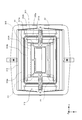
図19は、駆動部300の構成を示す斜視図である。 FIG. 19 is a perspective view showing the configuration of the drive unit 300.

駆動部300は、ホルダ321と、カバー322と、4つの板バネ323と、ワッシャー324と、ネジ325と、ベース326と、支持部材327と、ワッシャー328と、ネジ329と、支持部材330と、エンコーダ331と、磁気回路332とを備えている。可動スクリーン301は、ホルダ321に保持されている。カバー322には、開口322aが形成され、この開口322aから可動スクリーン301が露出している。また、カバー322には、開口322aからX軸方向およびY軸方向に延びる切欠き322bが形成されている。 The drive unit 300 includes a holder 321, a cover 322, four leaf springs 323, a washer 324, a screw 325, a base 326, a support member 327, a washer 328, a screw 329, a support member 330, and the like. It includes an encoder 331 and a magnetic circuit 332. The movable screen 301 is held in the holder 321. An opening 322a is formed in the cover 322, and the movable screen 301 is exposed from the opening 322a. Further, the cover 322 is formed with a notch 322b extending from the opening 322a in the X-axis direction and the Y-axis direction.

ホルダ321は、板バネ323によって、Z軸方向に移動可能に支持されている。板バネ323の端部が、ワッシャー324とネジ325によりホルダ321に固定されている。支持部材327がベース326に設置され、この支持部材327に、板バネ323がワッシャー328とネジ329により固定されている。さらに、ベース326には磁気回路332が設置されている。ホルダ321に保持されたコイル(図示せず)に磁気回路332から磁界が印加される。コイルに電流を流すことにより、ホルダ321がZ軸方向に駆動される。 The holder 321 is movably supported in the Z-axis direction by a leaf spring 323. The end of the leaf spring 323 is fixed to the holder 321 by a washer 324 and a screw 325. A support member 327 is installed on the base 326, and a leaf spring 323 is fixed to the support member 327 by a washer 328 and a screw 329. Further, a magnetic circuit 332 is installed on the base 326. A magnetic field is applied from the magnetic circuit 332 to the coil (not shown) held in the holder 321. By passing an electric current through the coil, the holder 321 is driven in the Z-axis direction.

図20は、磁気回路332の構成を示す分解斜視図である。 FIG. 20 is an exploded perspective view showing the configuration of the magnetic circuit 332.

磁気回路332は、第1のヨーク333と、第1の磁石334a、334bと、第2のヨーク335と、第2の磁石336a、336bとを備えている。 The magnetic circuit 332 includes a first yoke 333, a first magnet 334a and 334b, a second yoke 335, and a second magnet 336a and 336b.

ベース326は、平面視において略正方形の輪郭を有する。ベース326は、磁性体からなっている。ベース326には、開口326aと、複数のボス326bと、複数のネジ穴326cと、抜き孔326dが形成されている。開口326aは、図2に示す補正レンズ107からのレーザ光をZ軸正方向に通すためのものである。ボス326bは、ベース326上に設置される各部材を所定の位置に位置決めするためのものである。ネジ穴326cは、ベース326上に設置される各部材をネジで固定するためのものである。抜き孔326dは、ベース326上に各部材を設置する際に、ベース326の裏側からドライバー等のジグを挿入するためのものである。 The base 326 has a substantially square contour in plan view. The base 326 is made of a magnetic material. The base 326 is formed with an opening 326a, a plurality of bosses 326b, a plurality of screw holes 326c, and a punching hole 326d. The opening 326a is for passing the laser beam from the correction lens 107 shown in FIG. 2 in the positive direction of the Z axis. The boss 326b is for positioning each member installed on the base 326 at a predetermined position. The screw holes 326c are for fixing each member installed on the base 326 with screws. The punch hole 326d is for inserting a jig such as a driver from the back side of the base 326 when each member is installed on the base 326.

第1のヨーク333は、外側の壁部333aと内側の壁部333bとを備える。壁部333a、333bの互いに向き合う内側面に、それぞれ、第1の磁石334a、334bが装着される。また、第2のヨーク335は、外側の壁部335aと内側の壁部335bとを備える。壁部335a、335bの互いに向き合う内側面に、それぞれ、第2の磁石336a、336bが装着される。 The first yoke 333 includes an outer wall portion 333a and an inner wall portion 333b. The first magnets 334a and 334b are mounted on the inner side surfaces of the wall portions 333a and 333b facing each other, respectively. The second yoke 335 includes an outer wall portion 335a and an inner wall portion 335b. Second magnets 336a and 336b are mounted on the inner surfaces of the wall portions 335a and 335b facing each other, respectively.

なお、実施形態2では、実施形態1と異なり、第1のヨーク333の外側の壁部333aが2つに分離されていない。このため、壁部333aには、1つの第1の磁石334aが設置される。また、実施形態2では、実施形態1と異なり、第2のヨーク335の内側の壁部335bが2つに分離されており、これら2つの壁部335bに、それぞれ第2の磁石336bが設置される。なお、実施形態1と同様、第1のヨーク333は、Y軸方向に対称な形状であり、第2のヨーク335は、X軸方向に対称な形状である。 In the second embodiment, unlike the first embodiment, the outer wall portion 333a of the first yoke 333 is not separated into two. Therefore, one first magnet 334a is installed on the wall portion 333a. Further, in the second embodiment, unlike the first embodiment, the inner wall portion 335b of the second yoke 335 is separated into two, and the second magnet 336b is installed on each of the two wall portions 335b. NS. As in the first embodiment, the first yoke 333 has a shape symmetrical in the Y-axis direction, and the second yoke 335 has a shape symmetrical in the X-axis direction.

第1の磁石334a、334bが設置された状態で、X軸正側の第1のヨーク333が、ベース326の開口326aのX軸正側に設置され、X軸負側の第1のヨーク333が、ベース326の開口326aのX軸負側に設置される。また、第2の磁石336a、336bが設置された状態で、Y軸正側の第2のヨーク335が、ベース326の開口326aのY軸正側に設置され、Y軸負側の第2のヨーク335が、ベース326の開口326aのY軸負側に設置される。こうして、図21に示すように、磁気回路332がベース326上に設置される。 With the first magnets 334a and 334b installed, the first yoke 333 on the positive side of the X-axis is installed on the positive side of the X-axis of the opening 326a of the base 326, and the first yoke 333 on the negative side of the X-axis. Is installed on the negative side of the X-axis of the opening 326a of the base 326. Further, with the second magnets 336a and 336b installed, the second yoke 335 on the positive side of the Y-axis is installed on the positive side of the Y-axis of the opening 326a of the base 326, and the second yoke on the negative side of the Y-axis is installed. The yoke 335 is installed on the negative side of the Y-axis of the opening 326a of the base 326. Thus, as shown in FIG. 21, the magnetic circuit 332 is installed on the base 326.

図22は、ホルダ321、可動スクリーン301およびコイル337の組立て過程を示す斜視図である。 FIG. 22 is a perspective view showing an assembly process of the holder 321 and the movable screen 301 and the coil 337.

ホルダ321は、樹脂等の比重が小さい材料で一体形成されている。ホルダ321は、X軸方向に対称な形状を有している。ホルダ321は、可動スクリーン301が設置される略長方形の内枠321aと、コイル337が設置される略長方形の外枠321bとを備えている。内枠321aは、4つの橋部321cによって外枠321bに接続されている。X軸方向に並ぶ2つの橋部321cは、内枠321aのY軸方向の中央位置と、外枠321bのY軸方向の中央位置とを繋いでいる。また、Y軸方向に並ぶ2つの橋部321cは、内枠321aのX軸方向の中央位置と、外枠321bのX軸方向の中央位置とを繋いでいる。さらに、外枠321bの4つの角からそれぞれ放射状に延びるように、4つの被支持部321dが形成されている。 The holder 321 is integrally formed of a material having a small specific gravity such as resin. The holder 321 has a shape symmetrical in the X-axis direction. The holder 321 includes a substantially rectangular inner frame 321a on which the movable screen 301 is installed, and a substantially rectangular outer frame 321b on which the coil 337 is installed. The inner frame 321a is connected to the outer frame 321b by four bridge portions 321c. The two bridge portions 321c arranged in the X-axis direction connect the center position of the inner frame 321a in the Y-axis direction and the center position of the outer frame 321b in the Y-axis direction. Further, the two bridge portions 321c arranged in the Y-axis direction connect the center position of the inner frame 321a in the X-axis direction and the center position of the outer frame 321b in the X-axis direction. Further, four supported portions 321d are formed so as to extend radially from each of the four corners of the outer frame 321b.

なお、実施形態1と異なり実施形態2では、内枠321aが外枠321bに対して高さ方向(Z軸正方向)に変位して設けられている。また、上記実施形態1と同様、外枠321bはX−Y平面に平行に配置されるが、上記実施形態1と異なり、内枠321aは、X−Y平面に平行な面に対して傾いた状態で配置されている。 In addition, unlike the first embodiment, in the second embodiment, the inner frame 321a is provided so as to be displaced in the height direction (Z-axis positive direction) with respect to the outer frame 321b. Further, as in the first embodiment, the outer frame 321b is arranged parallel to the XY plane, but unlike the first embodiment, the inner frame 321a is tilted with respect to the plane parallel to the XY plane. It is arranged in a state.

内枠321aには、レーザ光を通すための開口321eが設けられている。開口321eは、平面視において略長方形の輪郭を有する。開口321eの周囲に複数の壁321fが設けられている。この壁321fの内側に、可動スクリーン301の端縁301aが嵌め込まれて、可動スクリーン301が内枠321aに装着される。端縁301aは、可動スクリーン301のその他の部分よりも肉厚となっている。可動スクリーン301は、接着剤により内枠321aに固定される。 The inner frame 321a is provided with an opening 321e for passing laser light. The opening 321e has a substantially rectangular contour in a plan view. A plurality of walls 321f are provided around the opening 321e. The edge 301a of the movable screen 301 is fitted inside the wall 321f, and the movable screen 301 is attached to the inner frame 321a. The edge 301a is thicker than the other parts of the movable screen 301. The movable screen 301 is fixed to the inner frame 321a with an adhesive.

また、外枠321bの下面には、Z軸負側に突出する鍔状の突起321gが複数形成されている。これら突起321gにコイル337の内側が嵌め込まれて、コイル337が外枠321bに装着される。コイル337は、接着剤により外枠321bに固定される。コイル337は、Z軸に平行な軸の周りを一方向に回るように構成されている。 Further, on the lower surface of the outer frame 321b, a plurality of brim-shaped protrusions 321g projecting on the negative side of the Z axis are formed. The inside of the coil 337 is fitted into these protrusions 321g, and the coil 337 is mounted on the outer frame 321b. The coil 337 is fixed to the outer frame 321b with an adhesive. The coil 337 is configured to rotate in one direction around an axis parallel to the Z axis.

被支持部321dの端部には、XY平面に平行な2つの鍔部321hが互いに向き合うように形成されている。これら鍔部321hのZ軸方向に並ぶ位置に、それぞれ、ネジ孔321iが形成されている。さらに、Y軸方向に並ぶ2つの被支持部321dを接続する梁部321jが形成され、この梁部321jのY軸方向の中央位置の外側面にスケール321kが設置されている。 At the end of the supported portion 321d, two flange portions 321h parallel to the XY plane are formed so as to face each other. Screw holes 321i are formed at positions of the collar portions 321h arranged in the Z-axis direction. Further, a beam portion 321j connecting two supported portions 321d arranged in the Y-axis direction is formed, and a scale 321k is installed on the outer surface of the beam portion 321j at the center position in the Y-axis direction.

図23は、ホルダ321、板バネ323および支持部材327の組立て過程を示す斜視図である。図23の4つの板バネ323は、全て同じ構造である。Y軸正側の2つの板バネ323と、Y軸負側の2つの板バネ323は、互いに表裏反転された関係にある。ここでは、便宜上、Y軸負側の上側の板バネ323について、構造の説明を行う。なお、図23では、便宜上、図19に示す板バネ323固定用のワッシャー324およびネジ325とワッシャー328およびネジ329の図示が省略されている。 FIG. 23 is a perspective view showing an assembly process of the holder 321 and the leaf spring 323 and the support member 327. The four leaf springs 323 in FIG. 23 all have the same structure. The two leaf springs 323 on the positive side of the Y-axis and the two leaf springs 323 on the negative side of the Y-axis are in an inverted relationship with each other. Here, for convenience, the structure of the upper leaf spring 323 on the negative side of the Y-axis will be described. In FIG. 23, for convenience, the washer 324 and the screw 325 and the washer 328 and the screw 329 for fixing the leaf spring 323 shown in FIG. 19 are not shown.

板バネ323は、可撓性の金属材料で一体形成されている。板バネ323の形状は、X軸方向に対称である。板バネ323のX軸方向の中央位置、すなわち、X軸方向の対称軸の位置に、2つの孔323a、323bと円弧状の切欠き323cが形成されている。また、板バネ323の両端に、孔323dが形成されている。板バネ323は、X軸方向の中央位置からX軸方向の両端に向かうに従って、Y軸方向の幅が徐々に小さくなっている。これにより、板バネ323のバネ定数を保ちながら、板バネ323の可動端部の軽量化が図られている。 The leaf spring 323 is integrally formed of a flexible metal material. The shape of the leaf spring 323 is symmetrical in the X-axis direction. Two holes 323a and 323b and an arc-shaped notch 323c are formed at the center position of the leaf spring 323 in the X-axis direction, that is, at the position of the axis of symmetry in the X-axis direction. Further, holes 323d are formed at both ends of the leaf spring 323. The width of the leaf spring 323 in the Y-axis direction gradually decreases from the central position in the X-axis direction toward both ends in the X-axis direction. As a result, the weight of the movable end of the leaf spring 323 is reduced while maintaining the spring constant of the leaf spring 323.

支持部材327は、樹脂等の非磁性材料により一体形成されている。支持部材327は、X軸方向に対称な形状を有する。支持部材327の上面には、X軸方向の中央位置に、ネジ穴327aと円柱状の2つの突部327bがY軸方向に並ぶように形成されている。さらに、支持部材327の上面には、中央からX軸方向の端部に進むに従って高さが低くなる2つの傾斜面327cが形成されている。なお、支持部材327の下面にも、上面と同様、ネジ穴327aおよび2つの突部327bと2つの傾斜面327cが形成されている。ネジ穴327a、突部327bおよび傾斜面327cが形成された支持部材327の部分は、Z軸方向に対称な形状となっている。 The support member 327 is integrally formed of a non-magnetic material such as resin. The support member 327 has a shape symmetrical in the X-axis direction. On the upper surface of the support member 327, a screw hole 327a and two cylindrical protrusions 327b are formed so as to line up in the Y-axis direction at a central position in the X-axis direction. Further, on the upper surface of the support member 327, two inclined surfaces 327c are formed, which decrease in height from the center toward the end in the X-axis direction. Similar to the upper surface, the lower surface of the support member 327 is also formed with screw holes 327a, two protrusions 327b, and two inclined surfaces 327c. The portion of the support member 327 on which the screw hole 327a, the protrusion 327b, and the inclined surface 327c are formed has a shape symmetrical in the Z-axis direction.

4つの板バネ323は、図23の一点鎖線の矢印に示すように、それぞれ、孔323dがホルダ321側のネジ孔321iに合わされた状態で、ワッシャー324およびネジ325(図19参照)により、ホルダ321にネジ止めされる。また、4つの板バネ323は、図23の一点鎖線の矢印に示すように、それぞれ、孔323aと切欠き323cが支持部材327の突部327bに嵌められ、孔323bがネジ穴327aに合わされる。この状態で、ワッシャー328を介してネジ329(図19参照)がネジ穴327aに留められる。これにより、板バネ323がホルダ321に固定される。 The four leaf springs 323 are held by the washer 324 and the screw 325 (see FIG. 19) in a state where the hole 323d is aligned with the screw hole 321i on the holder 321 side, respectively, as shown by the arrow of the alternate long and short dash line in FIG. It is screwed to 321. Further, in the four leaf springs 323, as shown by the arrow of the alternate long and short dash line in FIG. 23, the holes 323a and the notch 323c are fitted into the protrusions 327b of the support member 327, respectively, and the holes 323b are fitted into the screw holes 327a. .. In this state, the screw 329 (see FIG. 19) is fastened to the screw hole 327a via the washer 328. As a result, the leaf spring 323 is fixed to the holder 321.

図24は、ベース326に対する支持部材327、330とエンコーダ331の組立て過程を示す斜視図である。便宜上、図24では、磁気回路332が省略されている。 FIG. 24 is a perspective view showing an assembly process of the support members 327, 330 and the encoder 331 with respect to the base 326. For convenience, the magnetic circuit 332 is omitted in FIG. 24.

支持部材327は、ベース326のY軸正側の端部中央位置とY軸負側の端部中央位置に置かれて、ベース326の裏側からベース326にネジ止めされる。さらに、エンコーダ331が設置された支持部材330が、ベース326のX軸負側の端部中央位置に置かれて、ベース326の裏側からベース326にネジ止めされる。なお、ここでは、便宜上、ホルダ321、板バネ323および支持部材327を先に組み立てた後、支持部材327をベース326に組み付ける流れで説明を行ったが、先に支持部材327をベース326に設置した後、板バネ323を支持部材327に固定し、その後、ホルダ321を板バネ323の端部に固定してもよい。 The support member 327 is placed at the center position of the end on the positive side of the Y-axis and the center position of the end on the negative side of the Y-axis of the base 326, and is screwed to the base 326 from the back side of the base 326. Further, the support member 330 on which the encoder 331 is installed is placed at the center position of the end on the negative side of the X-axis of the base 326, and is screwed to the base 326 from the back side of the base 326. Here, for convenience, the flow of assembling the holder 321 and the leaf spring 323 and the support member 327 first and then assembling the support member 327 to the base 326 has been described, but the support member 327 is installed on the base 326 first. After that, the leaf spring 323 may be fixed to the support member 327, and then the holder 321 may be fixed to the end of the leaf spring 323.

こうして、ホルダ321がベース326に支持されると、支持部材330のエンコーダ331が、ホルダ321のX軸負側のスケール321kと対向する。上記実施形態1と同様、エンコーダ331は、Z軸方向におけるスケール321kの移動を光学的に検出するためのものである。 When the holder 321 is supported by the base 326 in this way, the encoder 331 of the support member 330 faces the scale 321k on the negative side of the X axis of the holder 321. Similar to the first embodiment, the encoder 331 is for optically detecting the movement of the scale 321k in the Z-axis direction.

図25は、カバー322が装着される前の駆動部300の構成を示す斜視図である。 FIG. 25 is a perspective view showing the configuration of the drive unit 300 before the cover 322 is attached.

上述の組み立てによって、図25に示す構造体が構成される。その後、図19に示すカバー322が磁気回路332の上面に重ねられる。このとき、カバー322の開口322aにホルダ321の内枠321aが通され、また、カバー322の切欠き322bにホルダ321の橋部321cが通される。カバー322は、磁性体からなっているため、磁気回路332の磁力により、磁気回路332を構成する第1のヨーク333と第2のヨーク335の上面に吸着される。これにより、カバー322の取り付けが完了し、図19に示す駆動部300が構成される。 The structure shown in FIG. 25 is constructed by the above assembly. After that, the cover 322 shown in FIG. 19 is superposed on the upper surface of the magnetic circuit 332. At this time, the inner frame 321a of the holder 321 is passed through the opening 322a of the cover 322, and the bridge portion 321c of the holder 321 is passed through the notch 322b of the cover 322. Since the cover 322 is made of a magnetic material, it is attracted to the upper surfaces of the first yoke 333 and the second yoke 335 constituting the magnetic circuit 332 by the magnetic force of the magnetic circuit 332. As a result, the attachment of the cover 322 is completed, and the drive unit 300 shown in FIG. 19 is configured.

図26は、カバー322を取り外した状態の駆動部300の構成を示す平面図である。 FIG. 26 is a plan view showing the configuration of the drive unit 300 with the cover 322 removed.

実施形態1と同様、破線の丸の領域A1において、第1のヨーク333の内側の壁部333bの側端面と第2のヨーク335の内側の壁部335bの外側面とが互いに重なりあうように、第1のヨーク333と第2のヨーク335が配置されている。また、この重なり部分において、第1のヨーク333の内側の壁部333bに設置された第1の磁石334bが、第2のヨーク335の内側の壁部335bの側端面まで延びている。この構成により、上記実施形態1と同様、より効率的に、コイル337に磁界を印加することができる。 Similar to the first embodiment, in the dashed circle area A1, the side end surface of the inner wall portion 333b of the first yoke 333 and the outer surface of the inner wall portion 335b of the second yoke 335 overlap each other. , The first yoke 333 and the second yoke 335 are arranged. Further, in this overlapping portion, the first magnet 334b installed on the inner wall portion 333b of the first yoke 333 extends to the side end surface of the inner wall portion 335b of the second yoke 335. With this configuration, a magnetic field can be applied to the coil 337 more efficiently as in the first embodiment.

また、実施形態1と同様、板バネ323は、可動スクリーン301の長辺に略平行に配置され、長手方向の中央位置においてベース326側に固定され、両端がホルダ321に接続されている。このように、板バネ323を可動スクリーン301の長辺に略平行に配置することにより、駆動部300をコンパクトに収めながら、板バネ323の固定位置P1から両端までの距離L1を長く確保できる。これにより、ホルダ321の駆動時に生じる板バネ323の応力が低減され、ホルダ321駆動時の負荷が軽減される。これにより、板バネ323の変形を防止し耐久性を高めることができる。 Further, as in the first embodiment, the leaf spring 323 is arranged substantially parallel to the long side of the movable screen 301, fixed to the base 326 side at the center position in the longitudinal direction, and both ends are connected to the holder 321. By arranging the leaf spring 323 substantially parallel to the long side of the movable screen 301 in this way, it is possible to secure a long distance L1 from the fixed position P1 of the leaf spring 323 to both ends while keeping the drive unit 300 compact. As a result, the stress of the leaf spring 323 generated when the holder 321 is driven is reduced, and the load when the holder 321 is driven is reduced. As a result, the leaf spring 323 can be prevented from being deformed and the durability can be improved.

<実施形態2の効果>
実施形態2の構成によっても、実施形態1と同様の効果が奏され得る。
<Effect of Embodiment 2>
The same effect as that of the first embodiment can be obtained by the configuration of the second embodiment.

なお、実施形態2では、図26に示すように、第1のヨーク333の外側の壁部333aと第2のヨーク335の外側の壁部335aとの間の隙間、および、第1のヨーク333の外側の壁部333aに設置された第1の磁石334aと第2のヨーク335の外側の壁部335aに設置された第2の磁石336aとの間の隙間を介して、外枠321bの4つの角部が、それぞれ板バネ323の端部に接続されている。このため、上記実施形態1に比べて、ホルダ321に捻れが生じにくくなり、ホルダ321および可動スクリーン301をより安定的に移動させることができるため、意図しない周波数でホルダ321および可動スクリーン301が振動することを抑制することができる。 In the second embodiment, as shown in FIG. 26, there is a gap between the outer wall portion 333a of the first yoke 333 and the outer wall portion 335a of the second yoke 335, and the first yoke 333. 4 of the outer frame 321b through the gap between the first magnet 334a installed on the outer wall portion 333a of the outer frame and the second magnet 336a installed on the outer wall portion 335a of the second yoke 335. Each of the two corners is connected to the end of the leaf spring 323. Therefore, as compared with the first embodiment, the holder 321 is less likely to be twisted, and the holder 321 and the movable screen 301 can be moved more stably. Therefore, the holder 321 and the movable screen 301 vibrate at an unintended frequency. Can be suppressed.

また、実施形態2では、図25に示すように、内枠321aが、磁気回路332の上端よりも高く位置づけられるように、外枠321bに対して高さ方向に変位して設けられている。これにより、上記実施形態1に比べて、第1のヨーク333の内側の壁部333bと第2のヨーク335の内側の壁部335bを、ベース326の中心側に寄せることができ、磁気回路332をコンパクトにすることができる。 Further, in the second embodiment, as shown in FIG. 25, the inner frame 321a is provided so as to be displaced in the height direction with respect to the outer frame 321b so as to be positioned higher than the upper end of the magnetic circuit 332. As a result, as compared with the first embodiment, the inner wall portion 333b of the first yoke 333 and the inner wall portion 335b of the second yoke 335 can be brought closer to the center side of the base 326, and the magnetic circuit 332 can be moved. Can be made compact.

また、実施形態2では、図26に示すように、第1のヨーク333の内側の壁部333bおよび第2のヨーク335の内側の壁部335bが、それぞれ幅方向に分離され、内枠321aと外枠321bとを繋ぐ橋部321cが、分離された第1のヨーク333の内側の壁部333bの間の隙間333cおよび分離された第2のヨーク335の内側の壁部335bの間の隙間335cを通っている。これにより、橋部321cの体積を抑制でき、ホルダ321の軽量化を図ることができる。よって、ホルダ321および可動スクリーン301のレスポンス性を高めることができる。また、図25に示すように、外枠321bから橋部321cが斜めに立ち上げられているため、図19に示すように、カバー322に切欠き322bを設けることにより、カバー322で磁気回路332を覆うことができる。 Further, in the second embodiment, as shown in FIG. 26, the inner wall portion 333b of the first yoke 333 and the inner wall portion 335b of the second yoke 335 are separated in the width direction, respectively, and are separated from the inner frame 321a. The bridge portion 321c connecting the outer frame 321b has a gap 335c between the inner wall portion 333b of the separated first yoke 333 and the inner wall portion 335b of the separated second yoke 335. Is passing through. As a result, the volume of the bridge portion 321c can be suppressed, and the weight of the holder 321 can be reduced. Therefore, the responsiveness of the holder 321 and the movable screen 301 can be improved. Further, as shown in FIG. 25, since the bridge portion 321c is obliquely raised from the outer frame 321b, as shown in FIG. 19, by providing the notch 322b in the cover 322, the magnetic circuit 332 is provided in the cover 322. Can be covered.

なお、図26に示す4つの橋部321cは、可動スクリーン301を安定的に支持できる限りにおいて、何れか1つまたは複数個を省略してもよい。また、橋部321cが磁気回路332を横切る位置は、図26に示す位置に限られるものではなく、他の位置であってもよい。また、橋部321cの数も適宜変更可能である。 One or more of the four bridge portions 321c shown in FIG. 26 may be omitted as long as the movable screen 301 can be stably supported. Further, the position where the bridge portion 321c crosses the magnetic circuit 332 is not limited to the position shown in FIG. 26, and may be another position. Further, the number of bridge portions 321c can be changed as appropriate.

図27に示すように、支持部材327を第2のヨーク335の外側の壁部335aにネジ327dで固定してもよい。また、図27に示すように、スケール321kを梁部321jの内側面に設置し、エンコーダ331を第2のヨーク335の外側の壁部335aに設置してもよい。これにより、平面視における駆動部300の外形を小さくすることができる。 As shown in FIG. 27, the support member 327 may be fixed to the outer wall portion 335a of the second yoke 335 with screws 327d. Further, as shown in FIG. 27, the scale 321k may be installed on the inner side surface of the beam portion 321j, and the encoder 331 may be installed on the outer wall portion 335a of the second yoke 335. As a result, the outer shape of the drive unit 300 in a plan view can be reduced.

<実施形態3>
上記実施形態2では、図23に示すように、中央から端部に向かうに伴って次第に幅が狭くなる板バネ323を用いてホルダ321が支持された。これに対し、本実施形態3では、それぞれ可動スクリーン301を短辺方向に挟む2対の板バネ323のうち少なくとも1対に、板バネ323の幅方向に蛇行する伸縮構造が設けられる。
<Embodiment 3>
In the second embodiment, as shown in FIG. 23, the holder 321 is supported by the leaf spring 323 whose width gradually narrows from the center toward the end. On the other hand, in the third embodiment, at least one pair of the two pairs of leaf springs 323 sandwiching the movable screen 301 in the short side direction is provided with a telescopic structure meandering in the width direction of the leaf springs 323.

図28(b)〜(d)それぞれ、実施形態3に係る板バネ323−1〜323−3の構成を示す平面図である。図28(a)には、実施形態2で用いた板バネ323が併せて示されている。 28 (b) to 28 (d) are plan views showing the configuration of leaf springs 323 to 1-23-3 according to the third embodiment, respectively. FIG. 28A also shows the leaf spring 323 used in the second embodiment.

図28(b)〜(d)に示すように、実施形態3で用いる板バネ323−1〜323−3には、中央両側に、クランク形状の伸縮構造323e〜323gが形成されている。伸縮構造323e〜323gは、それぞれ、板バネ323にY軸正側およびY軸負側から切り欠きC1を設けることにより形成されている。板バネ323−1〜323−3は、何れも長手方向に対称な形状である。板バネ323−2の伸縮構造323fは、板バネ323−1の伸縮構造323eに比べて、幅が狭くなっている。また、板バネ323−3の伸縮構造323gは、板バネ323−2の伸縮構造323fに比べて、蛇行部分の長さが長くなっている。 As shown in FIGS. 28 (b) to 28 (d), the leaf springs 323 to 1323-3 used in the third embodiment are formed with crank-shaped telescopic structures 323e to 323 g on both central sides. The telescopic structures 323e to 323g are formed by providing notches C1 on the leaf spring 323 from the positive side of the Y-axis and the negative side of the Y-axis, respectively. The leaf springs 323 to 1-23-3 are all symmetrical in the longitudinal direction. The telescopic structure 323f of the leaf spring 323-2 has a narrower width than the telescopic structure 323e of the leaf spring 323-1. Further, the telescopic structure 323g of the leaf spring 323-3 has a longer meandering portion than the telescopic structure 323f of the leaf spring 323-2.

このように、伸縮構造323e〜323gを設けることにより、板バネ323−1〜323−3は、実施形態2の板バネ323に比べて、Z軸方向に曲がりやすくなり、且つ、Y−Z平面に平行な方向に捻れやすくなる。また、伸縮構造323e〜323fの相違により、板バネ323−1〜323−3の中では、板バネ323−3が最も曲がりやすくなり、次に、板バネ323−2が曲がりやすくなる。 By providing the telescopic structures 323e to 323g in this way, the leaf springs 323-1 to 323-3 are more easily bent in the Z-axis direction than the leaf springs 323 of the second embodiment, and the YZ plane. It becomes easy to twist in the direction parallel to. Further, due to the difference between the telescopic structures 323e to 323f, the leaf spring 323-3 is the most easily bent among the leaf springs 323-13-23-3, and then the leaf spring 323-2 is easily bent.

図29(a)、(b)は、実施形態3に係る板バネ323−1〜323−3の反力特性および応力特性を示す図である。図29(a)、(b)には、実施形態2に係る板バネ323の反力特性および応力特性が併せて示されている。図29(a)において、横軸は、板バネ323、323−1〜323−3の曲げ量(中央部に対する端部の変位量)であり、縦軸は、端部に掛かる反力である。また、図29(b)において、横軸は、板バネ323、323−1〜323−3の曲げ量(中央部に対する端部の変位量)であり、縦軸は、板バネ323、323−1〜323−3に掛かる最大応力である。 29 (a) and 29 (b) are diagrams showing the reaction force characteristics and stress characteristics of the leaf springs 323-1-23-3 according to the third embodiment. 29 (a) and 29 (b) also show the reaction force characteristic and the stress characteristic of the leaf spring 323 according to the second embodiment. In FIG. 29 (a), the horizontal axis is the bending amount (displacement amount of the end portion with respect to the central portion) of the leaf springs 323 and 323-13-23-3, and the vertical axis is the reaction force applied to the end portion. .. Further, in FIG. 29B, the horizontal axis is the bending amount of the leaf springs 323 and 323-1-23-3 (the amount of displacement of the end portion with respect to the central portion), and the vertical axis is the leaf springs 323 and 323-3. This is the maximum stress applied to 1-3233-3.

図中のType0が実施形態2に係る板バネ323の特性を示し、Type1〜Type3が、それぞれ、板バネ323−1〜323−3の特性を示している。ここでは、板バネ323および板バネ323−1〜323−3は、それぞれ、全長が72.8mm、厚みが0.2mmであり、材料BeCuからなっている。板バネ323および板バネ323−1〜323−3において、中央部(固定部)と端部(支持部)を除いた2箇所の板バネとしての有効長は、それぞれ、29.1mmである。 Type 0 in the figure shows the characteristics of the leaf spring 323 according to the second embodiment, and Type 1 to Type 3 show the characteristics of the leaf springs 323 to 1-23-3, respectively. Here, the leaf spring 323 and the leaf spring 323-1-23-3 each have a total length of 72.8 mm and a thickness of 0.2 mm, and are made of the material BeCu. In the leaf spring 323 and the leaf springs 323 to 1323-3, the effective lengths of the two leaf springs excluding the central portion (fixed portion) and the end portion (support portion) are 29.1 mm, respectively.

図29(a)に示すように、実施形態2に係る板バネ323では、曲げ量の増加に伴い急激に反力が高まっている。このため、板バネ323を用いて可動スクリーン301の往復移動に必要な曲げ量を得ようとすると、板バネ323に大きな反力が生じ、駆動部300に大きな駆動力が必要となる。たとえば、実施形態2に係る板バネ323では、1mmの曲げ量(可動スクリーン301の移動量)を得ようとすると、4Nの駆動力が必要となる。また、このように反力が急激に高まり、反力特性の直線性が低下すると、可動スクリーン301の駆動制御が難しくなる。 As shown in FIG. 29A, in the leaf spring 323 according to the second embodiment, the reaction force sharply increases as the bending amount increases. Therefore, when the leaf spring 323 is used to obtain the bending amount required for the reciprocating movement of the movable screen 301, a large reaction force is generated in the leaf spring 323, and a large driving force is required in the drive unit 300. For example, in the leaf spring 323 according to the second embodiment, a driving force of 4N is required to obtain a bending amount of 1 mm (movement amount of the movable screen 301). Further, when the reaction force is rapidly increased and the linearity of the reaction force characteristic is lowered in this way, it becomes difficult to control the drive of the movable screen 301.

これに対し、実施形態3に係る板バネ323−1〜323−3では、図29(a)に示すように、実施形態2に係る板バネ323に比べて、曲げ量の増加に伴う反力の増加が緩やかになっており、反力特性の直線性が高まっている。このため、実施形態3に係る板バネ323−1〜323−3では、1mmの曲げ量(可動スクリーン301の移動量)を得るために、駆動力を2N以下に抑制でき、特に、板バネ323−2、323−3では、駆動力を1.5N程度まで抑制できる。また、板バネ323−1〜323−3では、反力特性の直線性が向上したため、可動スクリーン301の駆動制御を容易に行い得る。 On the other hand, in the leaf spring 323-1-23-3 according to the third embodiment, as shown in FIG. 29 (a), the reaction force due to the increase in the bending amount is compared with the leaf spring 323 according to the second embodiment. The increase is gradual, and the linearity of the reaction force characteristics is increasing. Therefore, in the leaf spring 323-1-23-3 according to the third embodiment, the driving force can be suppressed to 2N or less in order to obtain a bending amount of 1 mm (movement amount of the movable screen 301), and in particular, the leaf spring 323. In -2 and 323-3, the driving force can be suppressed to about 1.5N. Further, in the leaf springs 323 to 1-23-3, since the linearity of the reaction force characteristic is improved, the drive control of the movable screen 301 can be easily performed.

他方、図29(b)に示すように、板バネ323−1〜323−3では、伸縮構造323e〜323g部分の面積が低下するため、実施形態2の板バネ323に比べて最大応力が高くなる。ここで、最大応力が高くなるほど、板バネ323−1〜323−3の反復変形時の応力集中により、板バネ323−1〜323−3が破断するまでの寿命が短くなる。このため、板バネ323−1〜323−3の曲げ量に対する最大応力は、なるべく小さいことが好ましい。 On the other hand, as shown in FIG. 29 (b), in the leaf springs 323 to 1323-3, the area of the stretchable structure 323e to 323 g portion is reduced, so that the maximum stress is higher than that of the leaf spring 323 of the second embodiment. Become. Here, as the maximum stress becomes higher, the life until the leaf spring 323-1-23-3 breaks becomes shorter due to the stress concentration during repeated deformation of the leaf spring 323-13-23-3. Therefore, it is preferable that the maximum stress with respect to the bending amount of the leaf springs 323 to 1-23-3 is as small as possible.

たとえば、板バネ323−1では、1mmの曲げ量(可動スクリーン301の移動量)を得ようとすると、300N/mmを超える応力が生じる。これに対し、板バネ323−2、323−3では、1mmの曲げ量(可動スクリーン301の移動量)を得る場合の応力が、200N/mm程度に抑制される。これにより、たとえば、反復変形の回数が1010回を超える程度まで、板バネ323−2、323−3の寿命を延ばすことができる。したがって、長寿命化を図るためには、板バネ323−1よりも、板バネ323−2、323−3を用いることが好ましい。 For example, in the leaf spring 323-1, when trying to obtain a bending amount of 1 mm (moving amount of the movable screen 301), a stress exceeding 300 N / mm 2 is generated. On the other hand, with the leaf springs 323-2 and 323-3, the stress when obtaining a bending amount of 1 mm (moving amount of the movable screen 301) is suppressed to about 200 N / mm 2. Thereby, for example, the life of the leaf springs 323-2 and 323-3 can be extended to the extent that the number of repeated deformations exceeds 10 10 times. Therefore, in order to extend the service life, it is preferable to use leaf springs 323-2, 323-3 rather than leaf springs 323-1.

以上から、図28(b)〜(c)に示す板バネ323−1〜323−3を用いることにより、より小さい駆動力で安定的に、可動スクリーン301を往復移動させ得る。特に、板バネ323−2、323−3を用いることにより、可動スクリーン301の駆動制御をより容易かつ安定的に行うことができ、且つ、板バネ323−2、323−3の寿命をより長くできる。 From the above, by using the leaf springs 323-13-23-3 shown in FIGS. 28 (b) to 28 (c), the movable screen 301 can be stably reciprocated with a smaller driving force. In particular, by using the leaf springs 323-2 and 323-3, the drive control of the movable screen 301 can be performed more easily and stably, and the life of the leaf springs 323-2 and 323-3 is longer. can.

図30(a)は、ホルダ321を支持する4つの板バネとして実施形態2に係る板バネ323を用いた場合の周波数応答特性を示す図、図30(b)〜(d)は、それぞれ、ホルダ321を支持する4つの板バネとして実施形態3に係る板バネ323−1〜323−3を用いた場合の周波数応答特性を示す図である。図30(a)〜(d)には、シミュレーションに基づく周波数応答特性が示されている。 30 (a) is a diagram showing the frequency response characteristics when the leaf spring 323 according to the second embodiment is used as the four leaf springs supporting the holder 321. FIGS. 30 (b) to 30 (d) are respectively. It is a figure which shows the frequency response characteristic at the time of using the leaf spring 323-13-23-3 which concerns on Embodiment 3 as four leaf springs which support a holder 321. FIGS. 30 (a) to 30 (d) show frequency response characteristics based on the simulation.

図30(a)〜(d)を参照すると、実施形態2に係る板バネ323(Type0)を用いた場合に比べて、実施形態3に係る板バネ323−1〜323−3(Type1〜3)を用いた場合は、不要共振の振幅が抑制されていることが分かる。よって、実施形態3に係る板バネ323−1〜323−3を用いることにより、上述の効果、すなわち、安定的に、可動スクリーン301を往復移動させ得るとの効果が得られることが分かる。特に、板バネ323−3(Type3)を用いることにより、不要共振の振幅を顕著に抑制でき、且つ、周波数応答特性の直線性を高めることができる。これにより、板バネに設ける伸縮構造は、ホルダ321の変位による板バネの変形に、より円滑に追従可能なように、より幅狭で且つ長く形成することが好ましいと言える。すなわち、伸縮構造は、より柔らかくなるように構成することが好ましい。 With reference to FIGS. 30 (a) to 30 (d), the leaf springs 323 to 1-23-3 (Types 1 to 3) according to the third embodiment are compared with the case where the leaf springs 323 (Type 0) according to the second embodiment are used. ) Is used, it can be seen that the amplitude of unnecessary resonance is suppressed. Therefore, it can be seen that by using the leaf springs 323-13-23-3 according to the third embodiment, the above-mentioned effect, that is, the effect that the movable screen 301 can be stably reciprocated can be obtained. In particular, by using the leaf spring 323-3 (Type 3), the amplitude of unnecessary resonance can be remarkably suppressed, and the linearity of the frequency response characteristic can be improved. As a result, it can be said that the telescopic structure provided on the leaf spring is preferably formed to be narrower and longer so that the deformation of the leaf spring due to the displacement of the holder 321 can be more smoothly followed. That is, it is preferable that the stretchable structure is configured to be softer.

なお、図30(d)に示した板バネ323−3(Type3)の周波数応答特性では、2000Hzの周波数付近にゲインの変動が生じている。他方、上記のように可動スクリーン301を60Hz程度の周波数で駆動する場合、可動スクリーン301の停止動作や起動動作等、種々の複雑な制御動作を安定的に行うためには、サーボ系の制御帯域を2000Hz程度まで確保しておくことが好ましい。このため、2000Hz付近に生じているゲインの変動は、解消することが好ましい。 In the frequency response characteristic of the leaf spring 323-3 (Type 3) shown in FIG. 30 (d), the gain fluctuates in the vicinity of the frequency of 2000 Hz. On the other hand, when the movable screen 301 is driven at a frequency of about 60 Hz as described above, in order to stably perform various complicated control operations such as a stop operation and a start operation of the movable screen 301, the control band of the servo system is used. It is preferable to secure up to about 2000 Hz. Therefore, it is preferable to eliminate the fluctuation of the gain occurring in the vicinity of 2000 Hz.

この課題に対し、本願発明者らは、上記実施形態2における、ホルダ303を支持する4つの板バネのうち、Z軸正側の一対の板バネの座屈剛性と、Z軸負側の一対の板バネの座屈剛性とを、互いに相違させることを検討した。具体的には、Z軸正側の一対の板バネとして図28(a)〜(d)の何れか1つの板バネを用い、Z軸負側の一対の板バネとして図28(a)〜(d)の他の1つの板バネを用いることを検討した。 In response to this problem, the inventors of the present application have defined the buckling rigidity of a pair of leaf springs on the positive side of the Z axis and a pair of leaf springs on the negative side of the Z axis among the four leaf springs supporting the holder 303 in the second embodiment. It was examined to make the buckling rigidity of the leaf springs different from each other. Specifically, any one of the leaf springs shown in FIGS. 28 (a) to 28 (d) is used as the pair of leaf springs on the positive side of the Z axis, and the pair of leaf springs on the negative side of the Z axis are shown in FIGS. 28 (a) to 28 (d). It was considered to use another leaf spring of (d).

ここで、座屈剛性とは、図28(a)〜(d)の各板バネにおいて、X軸正方向またはX軸負方向の外力(圧縮または引っ張り)に対する変形し難さを示すもので、(荷重/変形量)で表すことができる。 Here, the buckling rigidity indicates the difficulty of deformation of each of the leaf springs of FIGS. 28 (a) to 28 (d) with respect to an external force (compression or tension) in the positive direction of the X-axis or the negative direction of the X-axis. It can be expressed as (load / deformation amount).

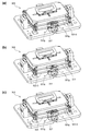
図31(a)〜(c)は、それぞれ、実施形態3に係る駆動部300の構成を示す斜視図である。図31(a)〜(c)では、支持部材327を破線で示して、板バネの中央付近が透視された状態となっている。 31 (a) to 31 (c) are perspective views showing the configuration of the drive unit 300 according to the third embodiment, respectively. In FIGS. 31A to 31C, the support member 327 is shown by a broken line, and the vicinity of the center of the leaf spring is seen through.

図31(a)の構成では、Z軸正側の一対の板バネとZ軸負側の一対の板バネが、何れも、図28(d)の板バネ323−3となっている。これに対し、図31(b)の構成では、Z軸正側の一対の板バネが図28(a)の板バネ323となっており、Z軸負側の一対の板バネが図28(d)の板バネ323−3となっている。また、図31(c)の構成では、Z軸正側の一対の板バネが図28(d)の板バネ323−3となっており、Z軸負側の一対の板バネが図28(a)の板バネ323となっている。 In the configuration of FIG. 31 (a), the pair of leaf springs on the positive side of the Z axis and the pair of leaf springs on the negative side of the Z axis are both the leaf springs 323-3 of FIG. 28 (d). On the other hand, in the configuration of FIG. 31 (b), the pair of leaf springs on the positive side of the Z axis is the leaf spring 323 of FIG. 28 (a), and the pair of leaf springs on the negative side of the Z axis is shown in FIG. 28 (a). It is a leaf spring 323-3 of d). Further, in the configuration of FIG. 31 (c), the pair of leaf springs on the positive side of the Z axis are the leaf springs 323-3 of FIG. 28 (d), and the pair of leaf springs on the negative side of the Z axis are shown in FIG. 28 (d). It is a leaf spring 323 of a).

したがって、図31(a)の構成では、Z軸正側の一対の板バネの座屈剛性と、Z軸負側の一対の板バネの座屈剛性とが、互いに同じとなっている。これに対し、図31(b)、(c)の構成では、Z軸正側の一対の板バネの座屈剛性と、Z軸負側の一対の板バネの座屈剛性とが、互いに相違している。 Therefore, in the configuration of FIG. 31A, the buckling rigidity of the pair of leaf springs on the positive side of the Z axis and the buckling rigidity of the pair of leaf springs on the negative side of the Z axis are the same. On the other hand, in the configurations of FIGS. 31 (b) and 31 (c), the buckling rigidity of the pair of leaf springs on the positive side of the Z axis and the buckling rigidity of the pair of leaf springs on the negative side of the Z axis are different from each other. doing.

図32(a)〜(c)は、それぞれ、図31(a)〜(c)に示した駆動部300の周波数応答特性(実測値)を示す図である。図32(a)〜(c)には、各駆動部300のゲイン特性が示されている。 32 (a) to 32 (c) are diagrams showing the frequency response characteristics (measured values) of the drive unit 300 shown in FIGS. 31 (a) to 31 (c), respectively. FIGS. 32 (a) to 32 (c) show the gain characteristics of each drive unit 300.

図32(a)を参照すると、2000Hzのやや手前において、ゲインの変動が生じている。このように、ゲインに変動が生じると、駆動部300の制御が不安定になる虞がある。 With reference to FIG. 32 (a), the gain fluctuates slightly before 2000 Hz. If the gain fluctuates in this way, the control of the drive unit 300 may become unstable.

これに対し、図32(b)を参照すると、図32(a)の場合に比べて、2000Hz付近のゲインの変動が抑制されている。また、図32(c)を参照すると、2000Hz付近のゲインの変動がさらに顕著に抑制されて、ピーク状の大きな変動が見られない。 On the other hand, referring to FIG. 32 (b), the fluctuation of the gain near 2000 Hz is suppressed as compared with the case of FIG. 32 (a). Further, referring to FIG. 32 (c), the fluctuation of the gain near 2000 Hz is further remarkably suppressed, and a large peak-like fluctuation is not observed.

以上から、Z軸正側の一対の板バネとZ軸負側の一対の板バネに互いに異なる板バネを用いて座屈剛性を相違させることにより、2000Hz付近までの帯域において、駆動部300のゲインを安定化させ得ることが確認できた。 From the above, by using different leaf springs for the pair of leaf springs on the positive side of the Z axis and the pair of leaf springs on the negative side of the Z axis to make the buckling rigidity different, the drive unit 300 can be used in the band up to about 2000 Hz. It was confirmed that the gain could be stabilized.

なお、このような作用は、以下の理由により達成されるものと考察される。 It is considered that such an action is achieved for the following reasons.

まず、図31(a)の構成では、Z軸正側の一対の板バネ323−3とZ軸負側の一対の板バネ323−3とは、構成が同一であり、座屈剛性が同じであるため、略同じ位相で振幅し、同じ共振周波数で共振する。この場合、上下の板バネ323−3とこれら板バネ323−3に挟まれた被支持部321dとで構成される共振系において、上下の板バネ323−3における共振モードが強められ、大きな振幅が生じる。これにより、図32(a)に示すように、2000Hz付近において、大きなゲインの変動が生じたものと考えられる。 First, in the configuration of FIG. 31A, the pair of leaf springs 323-3 on the positive side of the Z axis and the pair of leaf springs 323-3 on the negative side of the Z axis have the same configuration and the same buckling rigidity. Therefore, they oscillate in substantially the same phase and resonate at the same resonance frequency. In this case, in the resonance system composed of the upper and lower leaf springs 323-3 and the supported portion 321d sandwiched between the upper and lower leaf springs 323-3, the resonance mode in the upper and lower leaf springs 323-3 is strengthened and a large amplitude is obtained. Occurs. As a result, as shown in FIG. 32 (a), it is considered that a large gain fluctuation occurred in the vicinity of 2000 Hz.

これに対し、図31(b)の構成では、Z軸正側の一対の板バネ323とZ軸負側の一対の板バネ323−3とは、構成が異なっており、座屈剛性が相違するため、共振点が互いに相違する。このため、上下の板バネ323、323−3とこれら板バネ323、323−3で挟まれた被支持部321dとで構成される共振系において、上下の板バネ323、323−3における共振モードが強められることが起こりにくく、大きな振幅が生じることが抑制される。これにより、図32(b)に示すように、2000Hz付近において、大きなゲインの変動が抑制されたものと考えられる。 On the other hand, in the configuration of FIG. 31B, the pair of leaf springs 323 on the positive side of the Z axis and the pair of leaf springs 323-3 on the negative side of the Z axis are different in configuration and have different buckling rigidity. Therefore, the resonance points are different from each other. Therefore, in the resonance system composed of the upper and lower leaf springs 323 and 323-3 and the supported portion 321d sandwiched between the upper and lower leaf springs 323 and 323-3, the resonance mode in the upper and lower leaf springs 323 and 323-3 Is unlikely to be strengthened, and it is suppressed that a large amplitude is generated. As a result, as shown in FIG. 32 (b), it is considered that a large gain fluctuation was suppressed in the vicinity of 2000 Hz.

同様に、図31(c)の構成においても、Z軸正側の一対の板バネ323−3とZ軸負側の一対の板バネ323とは、構成が異なっており、座屈剛性が相違するため、共振点が互いに相違する。このため、図32(b)と同様、2000Hz付近において、大きなゲインの変動が抑制されたものと考えられる。 Similarly, also in the configuration of FIG. 31 (c), the pair of leaf springs 323-3 on the positive side of the Z axis and the pair of leaf springs 323 on the negative side of the Z axis are different in configuration and have different buckling rigidity. Therefore, the resonance points are different from each other. Therefore, as in FIG. 32 (b), it is considered that a large gain fluctuation is suppressed in the vicinity of 2000 Hz.

以上から、Z軸正側の一対の板バネとZ軸負側の一対の板バネの座屈剛性を相違させることにより、ゲインの変動を抑制できると考えられる。なお、図31(b)、(c)には、図28(a)、(d)の板バネ323、323−3の組み合わせを示したが、座屈剛性が異なる他の板バネの組み合わせであってもよい。たとえば、図28(b)、(d)の板バネ323−1、323−3の組み合わせや、図28(b)、(c)の板バネ323−1、323−2の組み合わせによっても、同様の効果が得られることが想定され得る。この他、図28(b)〜(d)以外のクランク形状の伸縮構造を有する板バネを用いてもよい。 From the above, it is considered that the fluctuation of the gain can be suppressed by making the buckling rigidity of the pair of leaf springs on the positive side of the Z axis and the pair of leaf springs on the negative side of the Z axis different. In addition, although the combination of the leaf springs 323 and 323-3 of FIGS. 28 (a) and 28 (d) is shown in FIGS. 31 (b) and 31 (c), the combination of other leaf springs having different buckling rigidity is used. There may be. For example, the combination of the leaf springs 323-1 and 323-3 of FIGS. 28 (b) and 28 (d) and the combination of the leaf springs 323-1 and 323-2 of FIGS. 28 (b) and 28 (c) are also the same. It can be assumed that the effect of In addition, a leaf spring having a crank-shaped telescopic structure other than those shown in FIGS. 28 (b) to 28 (d) may be used.

なお、板バネの対の数は、必ずしも2つでなくてもよく、3対以上の板バネがZ軸方向に配置されてもよい。この場合も、これら板バネの少なくとも1つに伸縮構造を形成して、反力の低減と、周波数応答の改善を図ることが好ましい。また、図28(b)〜(d)では、伸縮構造が、板バネの中央両側の中央側近位置に形成されたが、この位置から端部側にずれた位置に伸縮構造を配置してもよい。 The number of pairs of leaf springs does not necessarily have to be two, and three or more pairs of leaf springs may be arranged in the Z-axis direction. Also in this case, it is preferable to form an elastic structure on at least one of these leaf springs to reduce the reaction force and improve the frequency response. Further, in FIGS. 28 (b) to 28 (d), the telescopic structure is formed at a position near the center of both sides of the center of the leaf spring, but even if the telescopic structure is arranged at a position shifted from this position to the end side. good.

<その他の変更例>
以上、本発明の実施形態について説明したが、本発明は、上記実施形態に限定されるものではなく、また、本発明の適用例も、上記実施の形態の他に、種々の変更が可能である。
<Other changes>
Although the embodiments of the present invention have been described above, the present invention is not limited to the above-described embodiments, and various modifications can be made to the application examples of the present invention in addition to the above-described embodiments. be.

たとえば、上記実施形態1、2では、ホルダ303、321が樹脂で形成されたが、ホルダ303、321が、樹脂と軽量合金(たとえば、マグネシウム合金等)によるハイブリッド構造とされてもよい。この場合、渦電流の発生を抑制するため、少なくともコイル315、337と直接接触する部分は樹脂により構成し、好ましくは、コイル315、337に近接する部分も樹脂により構成する。ホルダ303、321は、軽量合金で形成する部分に樹脂で形成する部分をインサート成形することにより形成される。こうすると、軽量合金によりホルダ303、321の軽量化を図りながら機械的強度を保つことができ、樹脂により、電気的な障害を抑制できる。 For example, in the first and second embodiments, the holders 303 and 321 are made of resin, but the holders 303 and 321 may have a hybrid structure of resin and a lightweight alloy (for example, magnesium alloy). In this case, in order to suppress the generation of eddy current, at least the portion in direct contact with the coils 315 and 337 is made of resin, and preferably the portion close to the coils 315 and 337 is also made of resin. The holders 303 and 321 are formed by insert molding a portion formed of resin into a portion formed of a lightweight alloy. In this way, the lightweight alloy can reduce the weight of the holders 303 and 321 while maintaining the mechanical strength, and the resin can suppress electrical damage.

また、上記実施形態1、2では、本発明を乗用車1に搭載されるヘッドアップディスプレイに適用した例を示したが、本発明は、車載用に限らず、他の種類の画像表示装置にも適用可能である。 Further, in the above-described first and second embodiments, an example in which the present invention is applied to a head-up display mounted on a passenger car 1 is shown, but the present invention is not limited to in-vehicle use but also in other types of image display devices. Applicable.

また、画像表示装置20および照射光生成部21の構成は、図1(c)および図2に記載された構成に限られるものではなく、適宜、変更可能である。また、可動スクリーン301を移動させる駆動部300の構成も、実施形態1、2示した構成に限られるものではなく、適宜、変更可能である。 Further, the configurations of the image display device 20 and the irradiation light generation unit 21 are not limited to the configurations shown in FIGS. 1 (c) and 2 and can be changed as appropriate. Further, the configuration of the drive unit 300 for moving the movable screen 301 is not limited to the configurations shown in the first and second embodiments, and can be changed as appropriate.

本発明の実施の形態は、特許請求の範囲に示された技術的思想の範囲内において、適宜、種々の変更が可能である。 The embodiments of the present invention can be appropriately modified in various ways within the scope of the technical idea shown in the claims.

20 … 画像表示装置
22 … ミラー(光学系)
101 … 光源
201 … 画像処理回路(画像処理部)
300 … 駆動部
301 … 可動スクリーン(スクリーン、第1のスクリーン)
302 … 固定スクリーン(第2のスクリーン)
303 … ホルダ
303a … 内枠
303b … 外枠
303c、303j … 橋部
303d … 被支持部
304 … カバー
304a … 開口
305 … サスペンション
305b … 板バネ部(板バネ)
307 … ベース
310 … 磁気回路
311 … 第1のヨーク
311a、311b … 壁部
311c、311d、311f … 隙間
312a、312b … 第1の磁石
313 … 第2のヨーク
313a、313b … 壁部
314a、314b … 第2の磁石
321 … ホルダ
321a … 内枠
321b … 外枠
321c … 橋部
321d … 被支持部
322 … カバー
322a … 開口
323 … 板バネ
323−1〜323−3 … 板バネ
323e〜323g … 伸縮構造
326 … ベース
332 … 磁気回路
333 … 第1のヨーク
333a、333b … 壁部
333c、335c … 隙間
334a、334b … 第1の磁石
335 … 第2のヨーク
335a、335b … 壁部
336a、336b … 第2の磁石
20 ... Image display device 22 ... Mirror (optical system)
101 ... Light source 201 ... Image processing circuit (image processing unit)
300 ... Drive unit 301 ... Movable screen (screen, first screen)
302… Fixed screen (second screen)
303… Holder 303a… Inner frame 303b… Outer frame 303c, 303j… Bridge part 303d… Supported part 304… Cover 304a… Opening 305… Suspension 305b… Leaf spring part (leaf spring)
307 ... Base 310 ... Magnetic circuit 311 ... First yoke 311a, 311b ... Wall part 311c, 311d, 311f ... Gap 312a, 312b ... First magnet 313 ... Second yoke 313a, 313b ... Wall part 314a, 314b ... Second magnet 321 ... Holder 321a ... Inner frame 321b ... Outer frame 321c ... Bridge part 321d ... Supported part 322 ... Cover 322a ... Opening 323 ... Leaf spring 323-13-23-3 ... Leaf spring 323e to 323g ... Telescopic structure 326 ... Base 332 ... Magnetic circuit 333 ... First yoke 333a, 333b ... Wall part 333c, 335c ... Gap 334a, 334b ... First magnet 335 ... Second yoke 335a, 335b ... Wall part 336a, 336b ... Second Magnet

Claims (6)

光源と、
前記光源からの光が照射されることにより画像が形成される第1のスクリーンと、
前記光源からの光が照射されることにより画像が形成される第2のスクリーンと、
前記第1および第2のスクリーンからの光により虚像を生成する光学系と、
前記第1のスクリーンを光軸方向に往復移動させる駆動部と、
前記第1のスクリーンおよび前記第2のスクリーンに照射される前記光を映像信号に応じて変調させる画像処理部と、を備え、
前記駆動部による前記第1のスクリーンの往復移動に伴って動的な奥行き画像を表示するとともに、
前記第2のスクリーンによって静的画像を表示する、
ことを特徴とする画像表示装置。
Light source and
A first screen on which an image is formed by being irradiated with light from the light source, and
A second screen on which an image is formed by being irradiated with light from the light source, and
An optical system that creates a virtual image by the light from the first and second screens,
A drive unit that reciprocates the first screen in the optical axis direction,
E Bei and an image processing unit for modulating in accordance with a video signal of the light irradiated to the first screen and the second screen,
A dynamic depth image is displayed as the first screen reciprocates by the driving unit, and a dynamic depth image is displayed.
Displaying a static image by the second screen,
An image display device characterized by the fact that.
請求項1に記載の画像表示装置において、
前記第2のスクリーンは、前記駆動部により移動される前記第1のスクリーンの移動範囲の外側で、且つ、前記第1のスクリーンに対して前記光軸方向に垂直な方向に変位した位置に固定されている、
ことを特徴とする画像表示装置。
In the image display device according to claim 1,
The second screen is fixed at a position outside the moving range of the first screen moved by the driving unit and displaced in a direction perpendicular to the optical axis direction with respect to the first screen. Has been
An image display device characterized by the fact that.
請求項1または2に記載の画像表示装置において、
前記第2のスクリーンは、前記第1のスクリーンよりも、前記光源から光学的に離れた位置に配置されている、
ことを特徴とする画像表示装置。
In the image display device according to claim 1 or 2.
The second screen is arranged at a position optically distant from the light source than the first screen.
An image display device characterized by the fact that.
請求項1ないし3の何れか一項に記載の画像表示装置において、
前記第1のスクリーンは、略長方形の形状を有し、
前記第2のスクリーンは、前記第1のスクリーンの短辺に平行な方向に、前記第1のスクリーンから離れた位置に配置されている、
ことを特徴とする画像表示装置。
In the image display device according to any one of claims 1 to 3,
The first screen has a substantially rectangular shape and has a substantially rectangular shape.
The second screen is arranged at a position away from the first screen in a direction parallel to the short side of the first screen.
An image display device characterized by the fact that.
請求項1ないし4の何れか一項に記載の画像表示装置において、
前記第1のスクリーンおよび前記駆動部を覆うカバーを備え、
前記第2のスクリーンは、前記カバーに装着されている、
ことを特徴とする画像表示装置。
In the image display device according to any one of claims 1 to 4.
A cover covering the first screen and the drive unit is provided.
The second screen is attached to the cover.
An image display device characterized by the fact that.
請求項5に記載の画像表示装置において、
前記カバーは、前記第1のスクリーンからの光が通過する開口を備え、
前記第2のスクリーンは、前記開口の前記第1のスクリーンからの光が通過しない領域に配置されている、
ことを特徴とする画像表示装置。
In the image display device according to claim 5,
The cover comprises an opening through which light from the first screen passes.
The second screen is arranged in an area of the opening through which light from the first screen does not pass.
An image display device characterized by the fact that.
JP2020021945A 2016-01-26 2020-02-12 Image display device Active JP6948552B2 (en)

Applications Claiming Priority (3)

Application Number Priority Date Filing Date Title
JP2016012101 2016-01-26
JP2016184032A JP6675114B2 (en) 2016-01-26 2016-09-21 Image display device

Related Parent Applications (1)

Application Number Title Priority Date Filing Date
JP2016184032A Division JP6675114B2 (en) 2016-01-26 2016-09-21 Image display device

Publications (2)

Publication Number Publication Date
JP2020118976A JP2020118976A (en) 2020-08-06
JP6948552B2 true JP6948552B2 (en) 2021-10-13

Family

ID=59504860

Family Applications (2)

Application Number Title Priority Date Filing Date
JP2016184032A Active JP6675114B2 (en) 2016-01-26 2016-09-21 Image display device
JP2020021945A Active JP6948552B2 (en) 2016-01-26 2020-02-12 Image display device

Family Applications Before (1)

Application Number Title Priority Date Filing Date
JP2016184032A Active JP6675114B2 (en) 2016-01-26 2016-09-21 Image display device

Country Status (1)

Country Link
JP (2) JP6675114B2 (en)

Families Citing this family (2)

* Cited by examiner, † Cited by third party
Publication number Priority date Publication date Assignee Title
EP3719560A4 (en) 2017-11-30 2021-08-04 Nippon Seiki Co., Ltd. Head-up display
WO2023053342A1 (en) * 2021-09-30 2023-04-06 パイオニア株式会社 Optical scanning device and sensor device

Family Cites Families (11)

* Cited by examiner, † Cited by third party
Publication number Priority date Publication date Assignee Title
JPH06214189A (en) * 1993-01-19 1994-08-05 Mitsubishi Heavy Ind Ltd Route display system
JP4930071B2 (en) * 2007-01-23 2012-05-09 セイコーエプソン株式会社 Display device
JP5148960B2 (en) * 2007-09-21 2013-02-20 独立行政法人情報通信研究機構 Volume scanning type 3D aerial image display
JP2009150947A (en) * 2007-12-19 2009-07-09 Hitachi Ltd Head-up display device for vehicle
JP5198318B2 (en) * 2009-02-20 2013-05-15 日本電産サンキョー株式会社 Lens drive device
KR101131983B1 (en) * 2010-07-28 2012-03-29 안희경 A head-up display device for vehicle moving the projecting position of virtual images by the vehicle velocity
US9030749B2 (en) * 2012-08-01 2015-05-12 Microvision, Inc. Bifocal head-up display system
JP6138634B2 (en) * 2013-08-29 2017-05-31 アイシン・エィ・ダブリュ株式会社 Head-up display device
JP2015090377A (en) * 2013-11-05 2015-05-11 株式会社Suwaオプトロニクス Display optical system of display device
KR102071693B1 (en) * 2014-02-07 2020-01-30 엘지전자 주식회사 Head-Up Display Apparatus
JP6296862B2 (en) * 2014-03-31 2018-03-20 株式会社中日諏訪オプト電子 Image display device

Also Published As

Publication number Publication date
JP6675114B2 (en) 2020-04-01
JP2020118976A (en) 2020-08-06
JP2017134384A (en) 2017-08-03

Similar Documents

Publication Publication Date Title
US10031336B2 (en) Image display device
JP6948552B2 (en) Image display device
US7880571B2 (en) Two-axis driving electromagnetic micro-actuator
JP6846638B2 (en) Image display device
JP5402124B2 (en) Optical device, optical scanner, and image forming apparatus
JP6015564B2 (en) Optical scanning device
US9835859B2 (en) Image display device
JP6820501B2 (en) Image display device
JPWO2020008750A1 (en) Image display device and optical equipment
JP6455724B2 (en) Image display device
US10444501B2 (en) Image display device
JP6876932B2 (en) Image display device
JP2017097203A (en) Optical scanning device
JP5713083B2 (en) Optical device, optical scanner, and image forming apparatus
JP6667068B2 (en) Image display device
JP7151423B2 (en) display and mobile
JP2016011975A (en) Projector and head-up display
JP2018060029A (en) Mirror device and display device for vehicle
JP6660522B2 (en) Image display device
JP6703746B2 (en) Optical deflection element, optical scanning device, and image projection device
JP7249545B2 (en) Image display device and drive device
US20210278627A1 (en) Optical element driving mechanism
JP7159817B2 (en) display and mobile
JP2010266506A (en) Optical scanner and image forming apparatus equipped with the same
JP6695043B2 (en) Image display device and screen

Legal Events

Date Code Title Description
A621 Written request for application examination

Free format text: JAPANESE INTERMEDIATE CODE: A621

Effective date: 20200212

A977 Report on retrieval

Free format text: JAPANESE INTERMEDIATE CODE: A971007

Effective date: 20210129

A131 Notification of reasons for refusal

Free format text: JAPANESE INTERMEDIATE CODE: A131

Effective date: 20210202

A521 Request for written amendment filed

Free format text: JAPANESE INTERMEDIATE CODE: A523

Effective date: 20210316

TRDD Decision of grant or rejection written
A01 Written decision to grant a patent or to grant a registration (utility model)

Free format text: JAPANESE INTERMEDIATE CODE: A01

Effective date: 20210831

A61 First payment of annual fees (during grant procedure)

Free format text: JAPANESE INTERMEDIATE CODE: A61

Effective date: 20210831

R151 Written notification of patent or utility model registration

Ref document number: 6948552

Country of ref document: JP

Free format text: JAPANESE INTERMEDIATE CODE: R151

S111 Request for change of ownership or part of ownership

Free format text: JAPANESE INTERMEDIATE CODE: R313113

S531 Written request for registration of change of domicile

Free format text: JAPANESE INTERMEDIATE CODE: R313531

SZ03 Written request for cancellation of trust registration

Free format text: JAPANESE INTERMEDIATE CODE: R313Z03