JP6947868B2 - A method for manufacturing an electric unit for a vehicle having a plug-in connection part, a plug for the plug-in connection part of the electric unit, and a plug for the plug-in connection part of the electric unit. - Google Patents
A method for manufacturing an electric unit for a vehicle having a plug-in connection part, a plug for the plug-in connection part of the electric unit, and a plug for the plug-in connection part of the electric unit. Download PDFInfo
- Publication number
- JP6947868B2 JP6947868B2 JP2020054590A JP2020054590A JP6947868B2 JP 6947868 B2 JP6947868 B2 JP 6947868B2 JP 2020054590 A JP2020054590 A JP 2020054590A JP 2020054590 A JP2020054590 A JP 2020054590A JP 6947868 B2 JP6947868 B2 JP 6947868B2
- Authority
- JP
- Japan
- Prior art keywords
- plug
- end region
- contact
- housing
- contact terminal
- Prior art date
- Legal status (The legal status is an assumption and is not a legal conclusion. Google has not performed a legal analysis and makes no representation as to the accuracy of the status listed.)
- Active
Links
Images


Classifications
-
- H—ELECTRICITY
- H01—ELECTRIC ELEMENTS
- H01R—ELECTRICALLY-CONDUCTIVE CONNECTIONS; STRUCTURAL ASSOCIATIONS OF A PLURALITY OF MUTUALLY-INSULATED ELECTRICAL CONNECTING ELEMENTS; COUPLING DEVICES; CURRENT COLLECTORS
- H01R13/00—Details of coupling devices of the kinds covered by groups H01R12/70 or H01R24/00 - H01R33/00
- H01R13/46—Bases; Cases
- H01R13/52—Dustproof, splashproof, drip-proof, waterproof, or flameproof cases
-
- H—ELECTRICITY
- H01—ELECTRIC ELEMENTS
- H01R—ELECTRICALLY-CONDUCTIVE CONNECTIONS; STRUCTURAL ASSOCIATIONS OF A PLURALITY OF MUTUALLY-INSULATED ELECTRICAL CONNECTING ELEMENTS; COUPLING DEVICES; CURRENT COLLECTORS
- H01R13/00—Details of coupling devices of the kinds covered by groups H01R12/70 or H01R24/00 - H01R33/00
- H01R13/40—Securing contact members in or to a base or case; Insulating of contact members
- H01R13/405—Securing in non-demountable manner, e.g. moulding, riveting
-
- H—ELECTRICITY
- H01—ELECTRIC ELEMENTS
- H01R—ELECTRICALLY-CONDUCTIVE CONNECTIONS; STRUCTURAL ASSOCIATIONS OF A PLURALITY OF MUTUALLY-INSULATED ELECTRICAL CONNECTING ELEMENTS; COUPLING DEVICES; CURRENT COLLECTORS
- H01R13/00—Details of coupling devices of the kinds covered by groups H01R12/70 or H01R24/00 - H01R33/00
- H01R13/46—Bases; Cases
- H01R13/52—Dustproof, splashproof, drip-proof, waterproof, or flameproof cases
- H01R13/5202—Sealing means between parts of housing or between housing part and a wall, e.g. sealing rings
-
- F—MECHANICAL ENGINEERING; LIGHTING; HEATING; WEAPONS; BLASTING
- F01—MACHINES OR ENGINES IN GENERAL; ENGINE PLANTS IN GENERAL; STEAM ENGINES
- F01P—COOLING OF MACHINES OR ENGINES IN GENERAL; COOLING OF INTERNAL-COMBUSTION ENGINES
- F01P5/00—Pumping cooling-air or liquid coolants
- F01P5/02—Pumping cooling-air; Arrangements of cooling-air pumps, e.g. fans or blowers
-
- F—MECHANICAL ENGINEERING; LIGHTING; HEATING; WEAPONS; BLASTING
- F01—MACHINES OR ENGINES IN GENERAL; ENGINE PLANTS IN GENERAL; STEAM ENGINES
- F01P—COOLING OF MACHINES OR ENGINES IN GENERAL; COOLING OF INTERNAL-COMBUSTION ENGINES
- F01P5/00—Pumping cooling-air or liquid coolants
- F01P5/10—Pumping liquid coolant; Arrangements of coolant pumps
-
- F—MECHANICAL ENGINEERING; LIGHTING; HEATING; WEAPONS; BLASTING
- F04—POSITIVE - DISPLACEMENT MACHINES FOR LIQUIDS; PUMPS FOR LIQUIDS OR ELASTIC FLUIDS
- F04D—NON-POSITIVE-DISPLACEMENT PUMPS
- F04D1/00—Radial-flow pumps, e.g. centrifugal pumps; Helico-centrifugal pumps
-
- F—MECHANICAL ENGINEERING; LIGHTING; HEATING; WEAPONS; BLASTING
- F04—POSITIVE - DISPLACEMENT MACHINES FOR LIQUIDS; PUMPS FOR LIQUIDS OR ELASTIC FLUIDS
- F04D—NON-POSITIVE-DISPLACEMENT PUMPS
- F04D13/00—Pumping installations or systems
- F04D13/02—Units comprising pumps and their driving means
- F04D13/06—Units comprising pumps and their driving means the pump being electrically driven
- F04D13/0693—Details or arrangements of the wiring
-
- F—MECHANICAL ENGINEERING; LIGHTING; HEATING; WEAPONS; BLASTING
- F04—POSITIVE - DISPLACEMENT MACHINES FOR LIQUIDS; PUMPS FOR LIQUIDS OR ELASTIC FLUIDS
- F04D—NON-POSITIVE-DISPLACEMENT PUMPS
- F04D17/00—Radial-flow pumps, e.g. centrifugal pumps; Helico-centrifugal pumps
- F04D17/08—Centrifugal pumps
- F04D17/16—Centrifugal pumps for displacing without appreciable compression
-
- F—MECHANICAL ENGINEERING; LIGHTING; HEATING; WEAPONS; BLASTING
- F04—POSITIVE - DISPLACEMENT MACHINES FOR LIQUIDS; PUMPS FOR LIQUIDS OR ELASTIC FLUIDS
- F04D—NON-POSITIVE-DISPLACEMENT PUMPS
- F04D25/00—Pumping installations or systems
- F04D25/02—Units comprising pumps and their driving means
- F04D25/06—Units comprising pumps and their driving means the pump being electrically driven
- F04D25/0693—Details or arrangements of the wiring
-
- F—MECHANICAL ENGINEERING; LIGHTING; HEATING; WEAPONS; BLASTING
- F04—POSITIVE - DISPLACEMENT MACHINES FOR LIQUIDS; PUMPS FOR LIQUIDS OR ELASTIC FLUIDS
- F04D—NON-POSITIVE-DISPLACEMENT PUMPS
- F04D25/00—Pumping installations or systems
- F04D25/02—Units comprising pumps and their driving means
- F04D25/08—Units comprising pumps and their driving means the working fluid being air, e.g. for ventilation
-
- F—MECHANICAL ENGINEERING; LIGHTING; HEATING; WEAPONS; BLASTING
- F04—POSITIVE - DISPLACEMENT MACHINES FOR LIQUIDS; PUMPS FOR LIQUIDS OR ELASTIC FLUIDS
- F04D—NON-POSITIVE-DISPLACEMENT PUMPS
- F04D29/00—Details, component parts, or accessories
- F04D29/02—Selection of particular materials
- F04D29/023—Selection of particular materials especially adapted for elastic fluid pumps
-
- F—MECHANICAL ENGINEERING; LIGHTING; HEATING; WEAPONS; BLASTING
- F04—POSITIVE - DISPLACEMENT MACHINES FOR LIQUIDS; PUMPS FOR LIQUIDS OR ELASTIC FLUIDS
- F04D—NON-POSITIVE-DISPLACEMENT PUMPS
- F04D29/00—Details, component parts, or accessories
- F04D29/02—Selection of particular materials
- F04D29/026—Selection of particular materials especially adapted for liquid pumps
-
- F—MECHANICAL ENGINEERING; LIGHTING; HEATING; WEAPONS; BLASTING
- F04—POSITIVE - DISPLACEMENT MACHINES FOR LIQUIDS; PUMPS FOR LIQUIDS OR ELASTIC FLUIDS
- F04D—NON-POSITIVE-DISPLACEMENT PUMPS
- F04D29/00—Details, component parts, or accessories
- F04D29/06—Lubrication
- F04D29/061—Lubrication especially adapted for liquid pumps
-
- F—MECHANICAL ENGINEERING; LIGHTING; HEATING; WEAPONS; BLASTING
- F04—POSITIVE - DISPLACEMENT MACHINES FOR LIQUIDS; PUMPS FOR LIQUIDS OR ELASTIC FLUIDS
- F04D—NON-POSITIVE-DISPLACEMENT PUMPS
- F04D29/00—Details, component parts, or accessories
- F04D29/06—Lubrication
- F04D29/063—Lubrication specially adapted for elastic fluid pumps
-
- F—MECHANICAL ENGINEERING; LIGHTING; HEATING; WEAPONS; BLASTING
- F04—POSITIVE - DISPLACEMENT MACHINES FOR LIQUIDS; PUMPS FOR LIQUIDS OR ELASTIC FLUIDS
- F04D—NON-POSITIVE-DISPLACEMENT PUMPS
- F04D29/00—Details, component parts, or accessories
- F04D29/08—Sealings
-
- F—MECHANICAL ENGINEERING; LIGHTING; HEATING; WEAPONS; BLASTING
- F04—POSITIVE - DISPLACEMENT MACHINES FOR LIQUIDS; PUMPS FOR LIQUIDS OR ELASTIC FLUIDS
- F04D—NON-POSITIVE-DISPLACEMENT PUMPS
- F04D29/00—Details, component parts, or accessories
- F04D29/08—Sealings
- F04D29/083—Sealings especially adapted for elastic fluid pumps
-
- F—MECHANICAL ENGINEERING; LIGHTING; HEATING; WEAPONS; BLASTING
- F04—POSITIVE - DISPLACEMENT MACHINES FOR LIQUIDS; PUMPS FOR LIQUIDS OR ELASTIC FLUIDS
- F04D—NON-POSITIVE-DISPLACEMENT PUMPS
- F04D29/00—Details, component parts, or accessories
- F04D29/08—Sealings
- F04D29/086—Sealings especially adapted for liquid pumps
-
- F—MECHANICAL ENGINEERING; LIGHTING; HEATING; WEAPONS; BLASTING
- F04—POSITIVE - DISPLACEMENT MACHINES FOR LIQUIDS; PUMPS FOR LIQUIDS OR ELASTIC FLUIDS
- F04D—NON-POSITIVE-DISPLACEMENT PUMPS
- F04D29/00—Details, component parts, or accessories
- F04D29/40—Casings; Connections of working fluid
-
- F—MECHANICAL ENGINEERING; LIGHTING; HEATING; WEAPONS; BLASTING
- F04—POSITIVE - DISPLACEMENT MACHINES FOR LIQUIDS; PUMPS FOR LIQUIDS OR ELASTIC FLUIDS
- F04D—NON-POSITIVE-DISPLACEMENT PUMPS
- F04D29/00—Details, component parts, or accessories
- F04D29/40—Casings; Connections of working fluid
- F04D29/42—Casings; Connections of working fluid for radial or helico-centrifugal pumps
- F04D29/4206—Casings; Connections of working fluid for radial or helico-centrifugal pumps especially adapted for elastic fluid pumps
-
- F—MECHANICAL ENGINEERING; LIGHTING; HEATING; WEAPONS; BLASTING
- F04—POSITIVE - DISPLACEMENT MACHINES FOR LIQUIDS; PUMPS FOR LIQUIDS OR ELASTIC FLUIDS
- F04D—NON-POSITIVE-DISPLACEMENT PUMPS
- F04D29/00—Details, component parts, or accessories
- F04D29/40—Casings; Connections of working fluid
- F04D29/42—Casings; Connections of working fluid for radial or helico-centrifugal pumps
- F04D29/426—Casings; Connections of working fluid for radial or helico-centrifugal pumps especially adapted for liquid pumps
-
- H—ELECTRICITY
- H01—ELECTRIC ELEMENTS
- H01R—ELECTRICALLY-CONDUCTIVE CONNECTIONS; STRUCTURAL ASSOCIATIONS OF A PLURALITY OF MUTUALLY-INSULATED ELECTRICAL CONNECTING ELEMENTS; COUPLING DEVICES; CURRENT COLLECTORS
- H01R13/00—Details of coupling devices of the kinds covered by groups H01R12/70 or H01R24/00 - H01R33/00
- H01R13/46—Bases; Cases
- H01R13/52—Dustproof, splashproof, drip-proof, waterproof, or flameproof cases
- H01R13/5216—Dustproof, splashproof, drip-proof, waterproof, or flameproof cases characterised by the sealing material, e.g. gels or resins
-
- H—ELECTRICITY
- H01—ELECTRIC ELEMENTS
- H01R—ELECTRICALLY-CONDUCTIVE CONNECTIONS; STRUCTURAL ASSOCIATIONS OF A PLURALITY OF MUTUALLY-INSULATED ELECTRICAL CONNECTING ELEMENTS; COUPLING DEVICES; CURRENT COLLECTORS
- H01R13/00—Details of coupling devices of the kinds covered by groups H01R12/70 or H01R24/00 - H01R33/00
- H01R13/46—Bases; Cases
- H01R13/52—Dustproof, splashproof, drip-proof, waterproof, or flameproof cases
- H01R13/5219—Sealing means between coupling parts, e.g. interfacial seal
- H01R13/5221—Sealing means between coupling parts, e.g. interfacial seal having cable sealing means
-
- H—ELECTRICITY
- H01—ELECTRIC ELEMENTS
- H01R—ELECTRICALLY-CONDUCTIVE CONNECTIONS; STRUCTURAL ASSOCIATIONS OF A PLURALITY OF MUTUALLY-INSULATED ELECTRICAL CONNECTING ELEMENTS; COUPLING DEVICES; CURRENT COLLECTORS
- H01R13/00—Details of coupling devices of the kinds covered by groups H01R12/70 or H01R24/00 - H01R33/00
- H01R13/46—Bases; Cases
- H01R13/533—Bases, cases made for use in extreme conditions, e.g. high temperature, radiation, vibration, corrosive environment, pressure
-
- H—ELECTRICITY
- H01—ELECTRIC ELEMENTS
- H01R—ELECTRICALLY-CONDUCTIVE CONNECTIONS; STRUCTURAL ASSOCIATIONS OF A PLURALITY OF MUTUALLY-INSULATED ELECTRICAL CONNECTING ELEMENTS; COUPLING DEVICES; CURRENT COLLECTORS
- H01R13/00—Details of coupling devices of the kinds covered by groups H01R12/70 or H01R24/00 - H01R33/00
- H01R13/56—Means for preventing chafing or fracture of flexible leads at outlet from coupling part
-
- H—ELECTRICITY
- H01—ELECTRIC ELEMENTS
- H01R—ELECTRICALLY-CONDUCTIVE CONNECTIONS; STRUCTURAL ASSOCIATIONS OF A PLURALITY OF MUTUALLY-INSULATED ELECTRICAL CONNECTING ELEMENTS; COUPLING DEVICES; CURRENT COLLECTORS
- H01R13/00—Details of coupling devices of the kinds covered by groups H01R12/70 or H01R24/00 - H01R33/00
- H01R13/58—Means for relieving strain on wire connection, e.g. cord grip, for avoiding loosening of connections between wires and terminals within a coupling device terminating a cable
- H01R13/5845—Means for relieving strain on wire connection, e.g. cord grip, for avoiding loosening of connections between wires and terminals within a coupling device terminating a cable the strain relief being achieved by molding parts around cable and connections
-
- H—ELECTRICITY
- H01—ELECTRIC ELEMENTS
- H01R—ELECTRICALLY-CONDUCTIVE CONNECTIONS; STRUCTURAL ASSOCIATIONS OF A PLURALITY OF MUTUALLY-INSULATED ELECTRICAL CONNECTING ELEMENTS; COUPLING DEVICES; CURRENT COLLECTORS
- H01R43/00—Apparatus or processes specially adapted for manufacturing, assembling, maintaining, or repairing of line connectors or current collectors or for joining electric conductors
- H01R43/02—Apparatus or processes specially adapted for manufacturing, assembling, maintaining, or repairing of line connectors or current collectors or for joining electric conductors for soldered or welded connections
- H01R43/0207—Ultrasonic-, H.F.-, cold- or impact welding
-
- H—ELECTRICITY
- H01—ELECTRIC ELEMENTS
- H01R—ELECTRICALLY-CONDUCTIVE CONNECTIONS; STRUCTURAL ASSOCIATIONS OF A PLURALITY OF MUTUALLY-INSULATED ELECTRICAL CONNECTING ELEMENTS; COUPLING DEVICES; CURRENT COLLECTORS
- H01R43/00—Apparatus or processes specially adapted for manufacturing, assembling, maintaining, or repairing of line connectors or current collectors or for joining electric conductors
- H01R43/20—Apparatus or processes specially adapted for manufacturing, assembling, maintaining, or repairing of line connectors or current collectors or for joining electric conductors for assembling or disassembling contact members with insulating base, case or sleeve
- H01R43/24—Assembling by moulding on contact members
-
- F—MECHANICAL ENGINEERING; LIGHTING; HEATING; WEAPONS; BLASTING
- F05—INDEXING SCHEMES RELATING TO ENGINES OR PUMPS IN VARIOUS SUBCLASSES OF CLASSES F01-F04
- F05D—INDEXING SCHEME FOR ASPECTS RELATING TO NON-POSITIVE-DISPLACEMENT MACHINES OR ENGINES, GAS-TURBINES OR JET-PROPULSION PLANTS
- F05D2300/00—Materials; Properties thereof
- F05D2300/40—Organic materials
- F05D2300/43—Synthetic polymers, e.g. plastics; Rubber
-
- H—ELECTRICITY
- H01—ELECTRIC ELEMENTS
- H01R—ELECTRICALLY-CONDUCTIVE CONNECTIONS; STRUCTURAL ASSOCIATIONS OF A PLURALITY OF MUTUALLY-INSULATED ELECTRICAL CONNECTING ELEMENTS; COUPLING DEVICES; CURRENT COLLECTORS
- H01R2201/00—Connectors or connections adapted for particular applications
- H01R2201/26—Connectors or connections adapted for particular applications for vehicles
-
- H—ELECTRICITY
- H01—ELECTRIC ELEMENTS
- H01R—ELECTRICALLY-CONDUCTIVE CONNECTIONS; STRUCTURAL ASSOCIATIONS OF A PLURALITY OF MUTUALLY-INSULATED ELECTRICAL CONNECTING ELEMENTS; COUPLING DEVICES; CURRENT COLLECTORS
- H01R4/00—Electrically-conductive connections between two or more conductive members in direct contact, i.e. touching one another; Means for effecting or maintaining such contact; Electrically-conductive connections having two or more spaced connecting locations for conductors and using contact members penetrating insulation
- H01R4/02—Soldered or welded connections
- H01R4/023—Soldered or welded connections between cables or wires and terminals
-
- H—ELECTRICITY
- H01—ELECTRIC ELEMENTS
- H01R—ELECTRICALLY-CONDUCTIVE CONNECTIONS; STRUCTURAL ASSOCIATIONS OF A PLURALITY OF MUTUALLY-INSULATED ELECTRICAL CONNECTING ELEMENTS; COUPLING DEVICES; CURRENT COLLECTORS
- H01R4/00—Electrically-conductive connections between two or more conductive members in direct contact, i.e. touching one another; Means for effecting or maintaining such contact; Electrically-conductive connections having two or more spaced connecting locations for conductors and using contact members penetrating insulation
- H01R4/10—Electrically-conductive connections between two or more conductive members in direct contact, i.e. touching one another; Means for effecting or maintaining such contact; Electrically-conductive connections having two or more spaced connecting locations for conductors and using contact members penetrating insulation effected solely by twisting, wrapping, bending, crimping, or other permanent deformation
- H01R4/18—Electrically-conductive connections between two or more conductive members in direct contact, i.e. touching one another; Means for effecting or maintaining such contact; Electrically-conductive connections having two or more spaced connecting locations for conductors and using contact members penetrating insulation effected solely by twisting, wrapping, bending, crimping, or other permanent deformation by crimping
- H01R4/183—Electrically-conductive connections between two or more conductive members in direct contact, i.e. touching one another; Means for effecting or maintaining such contact; Electrically-conductive connections having two or more spaced connecting locations for conductors and using contact members penetrating insulation effected solely by twisting, wrapping, bending, crimping, or other permanent deformation by crimping for cylindrical elongated bodies, e.g. cables having circular cross-section
Description
本発明は、例えば、電気ウォーターポンプまたは電気ラジエーターファンのようなプラグイン連結部を有する車両用電気ユニット、電気ユニットのプラグイン連結部用プラグ、及び電気ユニットのプラグイン連結部用プラグの製造方法に関する。 The present invention is, for example, a method for manufacturing an electric unit for a vehicle having a plug-in connection part such as an electric water pump or an electric radiator fan, a plug for a plug-in connection part of the electric unit, and a plug for a plug-in connection part of the electric unit. Regarding.
本発明においては、車両用電気ユニットは、例えば、電気ウォーターポンプまたは電気ラジエーターファンを意味する。
電気ウォーターポンプは、一般的であり、例えば、米国登録特許 9360015 B1号公報に公知となっており、ステーターとローターを含む電気機械により駆動される。上記ローターは流体を移動させるためにポンプホイール(pump wheel)に連結される。上記流体はスパイラルの流入口を通じてポンプ内に流入して、ポンプホイールと接触してスパイラルの排出口を通過する。電気機械のローター及びステーターはスパイラルに連結されたハウジング内に含まれている。電気機械の電子装置は印刷回路基板(PCB)上に含まれている。上記印刷回路基板は電気機械の作動を電気的に制御する電子部品を含む。電源またはエネルギーは車両電気装置のケーブルハーネスに連結されたプラグを通じて供給される。この場合、電気接触端子(contact tongue)を通じて行われ、これら接触端子はケーブルハーネスのコア(個別ワイヤー)に電気的に連結されており、上記コア(個別ワイヤー)は印刷回路基板の対応する伝導性接触支持部と電気的にコンタクトされる。印刷回路基板とプラグの間のこのようなコンタクトは一般的にプラグイン連結部として設計されて、この場合、端部側に配置された接触端子を有するプラグは少なくとも部分的にウォーターポンプのハウジング内に挿入されて印刷回路基板にコンタクトされる。
In the present invention, the vehicle electric unit means, for example, an electric water pump or an electric radiator fan.
Electric water pumps are common and are, for example, known in US Registered Patent No. 9360015 B1 and are driven by an electrical machine that includes a stator and rotor. The rotor is connected to a pump wheel to move the fluid. The fluid flows into the pump through the inlet of the spiral, comes into contact with the pump wheel, and passes through the outlet of the spiral. The rotor and stator of the electromechanical machine are contained within a housing connected in a spiral. The electronic device of the electromechanical machine is included on the printed circuit board (PCB). The printed circuit board includes electronic components that electrically control the operation of an electric machine. Power or energy is supplied through a plug connected to the cable harness of the vehicle electrical equipment. In this case, it is done through electrical contact terminals, which are electrically connected to the core (individual wire) of the cable harness, which core (individual wire) corresponds to the conductivity of the printed circuit board. It is electrically contacted with the contact support. Such a contact between the printed circuit board and the plug is generally designed as a plug-in connection, in which case the plug with contact terminals located on the end side is at least partially within the housing of the water pump. It is inserted into the printed circuit board and contacted.
電気ラジエーターファンも、複数の実施形態で公知となっており、駆動可能なシャフト上で軸方向に配置されたファンホイール及び駆動用ファンモーターを含み、この場合、ファンホイールとファンモーターはハウジング内に配置されている。ハウジング内部には電気機械の作動を制御する電子装置もある。ラジエーターファンの場合も、電源またはエネルギーが車両電気装置のケーブルハーネスに連結されたプラグを通じて供給される。 Electric radiator fans are also known in a plurality of embodiments and include a fan wheel and a drive fan motor axially arranged on a driveable shaft, in which case the fan wheel and fan motor are in a housing. Have been placed. Inside the housing there is also an electronic device that controls the operation of the electromechanical machine. For radiator fans, power or energy is also supplied through a plug connected to the cable harness of the vehicle electrical equipment.
それと関連して、特に、自動車に用いられる時、上記のようなプラグイン連結部の問題点はプラグまたはプラグイン連結部の製造であるが、このようなプラグまたはプラグイン連結部は一方ではプラグ内にある、ケーブルのワイヤー端部と接触端子の間の接触領域が保護されるように十分に密封されており、そして、また、環境影響と関連して、特に、プラグのケーブルまたは個別ワイヤー及びワイヤーを収容するプラグキャリア(プラグハウジング)の間で湿度に対して十分な密封が提供されて結果的に湿気及び/またはガスがポンプハウジングの周辺からポンプハウジング内にまたはラジエーターファン周辺からプラグを通じてラジエーターファンのハウジング内に浸透することが防止される。 Related to that, especially when used in automobiles, the problem with plug-in connections as described above is the manufacture of plugs or plug-in connections, but such plugs or plug-in connections are plugs on the one hand. Inside, the contact area between the wire end of the cable and the contact terminal is well sealed to be protected, and also in relation to environmental impact, especially the plug cable or individual wire and Sufficient sealing against humidity is provided between the plug carriers (plug housings) that house the wires, resulting in moisture and / or gas flowing from around the pump housing into the pump housing or through the plug from around the radiator fan. It is prevented from penetrating into the fan housing.
本発明の課題の第1側面は、簡単で確実な電気コンタクトが達成されるようにウォーターポンプまたはラジエーターファンのようなプラグイン連結部を有する車両用電気ユニットを形成することであり、上記電気ユニットは、特に、プラグケーブルの個別ワイヤーの被覆が剥けた端部と接触端子の間の連結部の領域が密封されて、特にプラグを通じて上記ユニットの周辺から上記ユニットのハウジング内にワイヤーに沿って流入される湿気に対して十分な気密性が保障されることを特徴とする。 A first aspect of the present invention is to form a vehicle electrical unit having a plug-in connection such as a water pump or radiator fan so that simple and reliable electrical contact can be achieved. In particular, the area of the connection between the stripped end of the individual wire of the plug cable and the contact terminal is sealed and flows along the wire from around the unit into the housing of the unit, especially through the plug. It is characterized in that sufficient airtightness is guaranteed against the moisture that is generated.
上記課題の第2側面は、ウォーターポンプまたはラジエーターファンのような電気ユニットのプラグイン連結部用プラグを改善することであり、この場合、上記プラグは特にストレインリリーフ(strain relief)機能を有する必要があり、そして、この時、上記プラグは接触端子とケーブルのワイヤー端部の間の電気コンタクト領域に、特に、湿気に対した密封部を有し、特にケーブルから接触端子の方向にプラグハウジング内にワイヤーに沿って流入する湿気に対して十分な気密性が保障される。 The second aspect of the above task is to improve the plug for the plug-in connection of an electric unit such as a water pump or a radiator fan, in which case the plug needs to have a particularly strain relief function. And, at this time, the plug has an electrical contact area between the contact terminal and the wire end of the cable, especially a seal against moisture, especially in the plug housing in the direction of the contact terminal from the cable. Sufficient airtightness is guaranteed against moisture flowing in along the wire.
追加課題である本発明の第3側面は、電気ユニットのプラグイン連結部用プラグを製造するための方法である。この場合、特に、コスト面で経済的であるだけではなく、迅速で自動化が可能な方法を提供しなければならない。 A third aspect of the present invention, which is an additional subject, is a method for manufacturing a plug for a plug-in connecting portion of an electric unit. In this case, in particular, it must provide a method that is not only cost-effective, but also fast and automated.
下記に説明する密封措置は、環境影響と関連した密封部である。本発明において環境影響は不純物、ホコリ、水、オイル及び静電気放電(electrostatic discharge)のような大気影響を意味する。 The sealing measures described below are seals associated with environmental impact. In the present invention, environmental effects mean atmospheric effects such as impurities, dust, water, oil and electrostatic discharge.
上記課題の第1側面は請求項1の特徴によって解決される。
The first aspect of the above problem is solved by the feature of
上記課題の第2側面は請求項4の特徴によって解決される。この場合、特に、プラグ内ケーブルの個別ワイヤーの被覆が剥けた端部と接触端子の間の電気接続領域で密封が改善される。また、ケーブルまたは個別ワイヤーの縦方向に密封、特に、ケーブル被覆、ワイヤーの外部被覆とプラグハウジングの間で密封が達成されて、その結果、プラグ領域でプラグイン連結部に流入される環境影響の浸透、例えば、ウォーターポンプまたはラジエーターファンのようなユニットのハウジング内に流入される環境影響の浸透が防止される。 The second aspect of the above problem is solved by the feature of claim 4. In this case, sealing is improved, especially in the electrical connection area between the stripped ends of the individual wires of the cable within the plug and the contact terminals. Also, longitudinal sealing of the cable or individual wire, in particular the sealing between the cable coating, the outer coating of the wire and the plug housing, is achieved, resulting in the environmental impact of flowing into the plug-in connection in the plug area. Penetration, eg, penetration of environmental impacts flowing into the housing of a unit such as a water pump or radiator fan is prevented.
さらに、本発明によるプラグはケーブルの個別ワイヤーがストレインリリーフ方式でプラグハウジングに結合されるように形成されている。それは個別ワイヤーがプラグハウジングの対応するホールを通じて挿入されて、そして上記貫通領域から熱処理(熱圧法)により個別ワイヤーとプラグハウジングの間の強制結合(材料結合)方式の連結が形成されることによって達成される。 Further, the plug according to the present invention is formed so that the individual wires of the cable are connected to the plug housing by a strain relief method. It is achieved by inserting individual wires through the corresponding holes in the plug housing and then forming a forced bond (material bond) type connection between the individual wires and the plug housing by heat treatment (thermal pressure method) from the penetration region. Will be done.
個別ワイヤーと接触端子の間の連結部領域で樹脂からなった密封材料(上記連結部を包む)は上記領域の密封部であり、追加でプラグを通じて電気ユニットの周辺から上記電気ユニットのハウジング内に個別ワイヤーに沿って流入される湿気のような大気影響に対するバリヤーを示す。 The sealing material made of resin (wrapping the connecting portion) in the connecting portion region between the individual wire and the contact terminal is the sealing portion in the region, and additionally through a plug from the periphery of the electric unit into the housing of the electric unit. Shows a barrier to atmospheric effects such as moisture flowing along individual wires.
本発明の課題の第1及び第2側面を解決する他の実施形態で、個別ワイヤーの被覆が剥けた端部はかしめ連結(crimp connection)を通じて接触端子に連結されている。上記かしめ連結はワイヤー端部と接触端子の間の確実な連結を意味する。本実施例で、個別ワイヤーと接触端子の間の密封は上記連結領域を包んで同時にプラグハウジングのベースキャリア内に部分的に埋め込まれた熱可塑性材料により形成される。それで、個別ワイヤーのプラスチック被覆と熱可塑性材料の接着により行われる、上述の密封機能に加えて、個別ワイヤーのストレインリリーフも達成できる。 In another embodiment that solves the first and second aspects of the subject of the present invention, the stripped ends of the individual wires are connected to the contact terminals through a crimp connection. The caulking connection means a secure connection between the wire end and the contact terminal. In this embodiment, the seal between the individual wires and the contact terminals is formed by a thermoplastic material that wraps the connecting area and at the same time is partially embedded in the base carrier of the plug housing. Thus, in addition to the sealing function described above, which is performed by bonding the plastic coating of the individual wires to the thermoplastic material, strain relief of the individual wires can also be achieved.
本発明の改善例では、プラグイン連結部のプラグが圧力補償ダクトを備え、上記圧力補償ダクトはウォーターポンプまたはラジエーターファンのような電気ユニットのハウジングの内部とウォーターポンプまたはラジエーターファンのような電気ユニットの周辺間の圧力補償を可能にする。このような好ましい実施例を通じて、通気(圧力補償)機能がプラグに統合提供されることができ、その結果、ハウジングの異なる位置で別途の圧力補償を省略することができる。 In an improved example of the present invention, the plug of the plug-in connection is provided with a pressure compensation duct, which is inside the housing of an electric unit such as a water pump or radiator fan and an electric unit such as a water pump or radiator fan. Allows pressure compensation between the periphery of the. Through such preferred embodiments, ventilation (pressure compensation) functionality can be provided integrated into the plug, so that separate pressure compensation can be omitted at different locations in the housing.
好ましく、圧力補償ダクトは流入または排出開口領域でメンブレンを有する。好ましくはゴアテックス(登録商標)(Gore−tex(登録商標))メンブレンが提供される。それで、ハウジングの内部と電気ユニットの周辺間の連結を形成する圧力補償領域でも湿気のような環境影響と関連した密封が達成できる。 Preferably, the pressure compensating duct has a membrane in the inflow or outflow opening area. Preferably, a Gore-Tex® membrane is provided. Thus, sealing associated with environmental impacts such as moisture can also be achieved in the pressure compensating area that forms the connection between the interior of the housing and the periphery of the electrical unit.
さらに好ましくは、メンブレンを有する流入または排出開口がプラグの領域に配置されており、この時、上記領域はウォーターポンプまたはラジエーターファンのような電気ユニットと組み立てられた後は、ハウジング内部にある。この時、メンブレンはポンプまたはラジエーターファンハウジングで保護された位置に配置される。
本発明の第3側面は請求項13または14によるプラグ製造方法によって解決される。
More preferably, an inflow or outflow opening with a membrane is located in the area of the plug, where the area is inside the housing after being assembled with an electrical unit such as a water pump or radiator fan. At this time, the membrane is placed in a position protected by the pump or radiator fan housing.
The third aspect of the present invention is solved by the plug manufacturing method according to
上記方法は特に、迅速であるだけではなく自動化した方式で行われる。それはプラグの第1実施例によって、接触端子が第1方法段階でロールから供給されることによって達成できる。ワイヤー端部と接触端子の間のコンタクト領域でバリヤーとして密封部は好ましくは鋳造工程で密封材料により形成される。 The above method is particularly quick and automated. That can be achieved by supplying the contact terminals from the roll in the first method step according to the first embodiment of the plug. As a barrier in the contact area between the wire end and the contact terminal, the sealing portion is preferably formed of a sealing material during the casting process.
本発明による方法の改善例によれば、圧力補償ダクトを密封するためのメンブレンはロールから供給される。その結果、個別化したメンブレン要素は把持して適用する必要がないため、流入及び排出開口領域でメンブレンの適用を単純化させる。
メンブレンは好ましくは超音波溶接工程を通じて固定される。
According to an improved example of the method according to the invention, the membrane for sealing the pressure compensating duct is supplied from a roll. As a result, the individualized membrane elements do not need to be gripped and applied, simplifying the application of the membrane in the inflow and outflow opening regions.
The membrane is preferably fixed through an ultrasonic welding process.
本発明のプラグの第2実施変形例によれば、特にワイヤー端部と接触端子の間のかしめ連結を形成することによって、本発明による方法が単純化する。この場合、ワイヤーとプラグハウジング領域でストレインリリーフ及び密封は接触端子のための収容部であるベースキャリアの部分領域及び接触端子とのかしめ連結領域のワイヤーを圧出することによって、迅速であるだけではなく、確実に達成できる。この場合、材料としては、好ましく熱可塑性材料が用いられる。 According to a second embodiment of the plug of the present invention, the method according to the invention is simplified, in particular by forming a caulking connection between the wire end and the contact terminal. In this case, strain relief and sealing in the wire and plug housing area is not only quick by extruding the wire in the partial area of the base carrier which is the accommodating part for the contact terminal and the caulking connection area with the contact terminal. , Can be achieved with certainty. In this case, a thermoplastic material is preferably used as the material.
続いて、好ましく、第2実施例の方法では、個別ワイヤーと接触端子の間の接触点を密封するためのバリヤー領域とプラグの第2端部領域が熱可塑性材料により達成できる。それで、製造工程が特に時間と関連して最適化する。鋳造樹脂を用いる場合に必要な硬化時間が省略される。 Subsequently, preferably, in the method of the second embodiment, the barrier region for sealing the contact point between the individual wire and the contact terminal and the second end region of the plug can be achieved by the thermoplastic material. So the manufacturing process is optimized especially in relation to time. The curing time required when using a cast resin is omitted.
次いで、本発明は実施例により説明し、添付の図面が参照になる。
図1及び2は従来技術で公知となった電気ウォーターポンプを図示する。電気ウォーターポンプは、ステーター(24)及びローター(26)を含む電気機械により駆動される。ローター(26)は流体を移動させるためのポンプホイール(28)に連結される。上記流体はスパイラル(10)の流入口(12)を通じてウォーターポンプ内に流入して、パルプホイール(28)と接触してスパイラル(10)の排出口(14)を通過する。電気機械のローター(26)及びステーター(24)はスパイラル(10)に連結されたハウジング(20)内に含まれている。電気機械を制御するのに必要な電子装置は印刷回路基板(PCB)上に含まれており、接触支持部に連結されている。電子装置の電源またはエネルギーはプラグ(1)の接触端子と接触支持部または印刷回路基板の間のプラグイン連結部により供給される。上記接触端子は供給ライン(46)(ケーブルハーネス)の個別ワイヤーと電気的にコンタクトされており、絶縁された状態でプラグ(1)内に密封されている。組立ての間、プラグ(1)は端部側に配置された接触端子が少なくとも部分的にウォーターポンプのハウジング内に挿入される。この場合、接触端子は印刷回路基板の接触支持部内に挿入されて、プラグ(1)と印刷回路基板の間の電気コンタクトが形成される。図面において、プラグ(1)または接触端子及び印刷回路基板の接触支持部を含むプラグイン連結部は図示しない。 FIGS. 1 and 2 illustrate an electric water pump known in the prior art. The electric water pump is driven by an electrical machine that includes a stator (24) and a rotor (26). The rotor (26) is connected to a pump wheel (28) for moving the fluid. The fluid flows into the water pump through the inlet (12) of the spiral (10), contacts the pulp wheel (28), and passes through the outlet (14) of the spiral (10). The rotor (26) and stator (24) of the electromechanical machine are contained within a housing (20) connected to a spiral (10). The electronics required to control the electromechanical are contained on a printed circuit board (PCB) and are connected to a contact support. The power or energy of the electronic device is supplied by the contact terminal of the plug (1) and the contact support or the plug-in connection between the printed circuit board. The contact terminals are electrically contacted with individual wires of the supply line (46) (cable harness) and are sealed in the plug (1) in an insulated state. During assembly, the plug (1) is at least partially inserted into the housing of the water pump with contact terminals located on the end side. In this case, the contact terminal is inserted into the contact support portion of the printed circuit board to form an electrical contact between the plug (1) and the printed circuit board. In the drawings, the plug-in connection portion including the plug (1) or the contact terminal and the contact support portion of the printed circuit board is not shown.
図1及び2は、ウォーターポンプ(2)のハウジング(20)上にプラグ(1、1’)配置を概略的に図示する。上述したように、上記プラグ(1、1’)はプラグイン連結部を形成するために自動車内電気ユニットの複数のカウンタープラグ接点(接触支持部)と電気的にコンタクトされ得る。 FIGS. 1 and 2 schematically illustrate the arrangement of plugs (1, 1') on the housing (20) of the water pump (2). As described above, the plugs (1, 1') can be electrically contacted with a plurality of counter plug contacts (contact supports) of an in-vehicle electrical unit to form a plug-in connection.
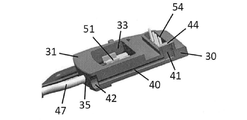
図3及び4は、プラグイン連結部がウォーターポンプ(2)のハウジング(20)上に組み立てられた状態でプラグ(1)を図示する。カウンタープラグ接点(接触支持部)を有する印刷回路基板は図示しない。図面に示すように、プラグ(1)の第1端部領域(30)は、組み立てられた状態でウォーターポンプ(2)のハウジング(20)内部にあり、供給ケーブル(46)を有する、対向する第2端部領域(31)は、ウォーターポンプ(2)のハウジング(20)から突出している。好ましくは、プラグ(1)の第1端部領域(30)は、空気空間を含み、圧力補償を必要とするウォーターポンプ(2)の領域内に配置されている。圧力補償を可能にするために、プラグ(1)は圧力補償ダクト(40)を備えて、上記圧力補償ダクト(40)はプラグの第1端部領域(30)内に配置された流入または排出開口(41)からプラグ(1)の第2端部領域(31)内に配置された流入または排出開口(42)につながっている。プラグ(1)がハウジング(20)内に組み立てられた後、ハウジング(20)内空気空間とウォーターポンプ(2)の周辺空間(U)の間の連結部が形成される。プラグ(1)の第1端部領域(30)に配置された流入/排出開口(41)はメンブレン(44)、好ましくはゴアテックスメンブレンで覆われており、したがって、通気開口を形成し、このような通気開口は同様に湿気の浸透を防止する。ハウジング(20)内部へのメンブレン(44)配置により、メンブレン(44)は外部から保護される。代案的にメンブレン(44)は、また、第2端部領域(31)の流入/排出開口(42)にも設計され得る。 3 and 4 show the plug (1) with the plug-in connection assembled on the housing (20) of the water pump (2). A printed circuit board having a counter plug contact (contact support portion) is not shown. As shown in the drawing, the first end region (30) of the plug (1), as assembled, is inside the housing (20) of the water pump (2) and has a supply cable (46) facing each other. The second end region (31) projects from the housing (20) of the water pump (2). Preferably, the first end region (30) of the plug (1) is located within the region of the water pump (2) that includes air space and requires pressure compensation. To enable pressure compensation, the plug (1) is provided with a pressure compensating duct (40), the pressure compensating duct (40) being placed in the first end region (30) of the plug for inflow or outflow. The opening (41) leads to an inflow or discharge opening (42) located within the second end region (31) of the plug (1). After the plug (1) is assembled in the housing (20), a connection is formed between the air space inside the housing (20) and the peripheral space (U) of the water pump (2). The inflow / outflow opening (41) located in the first end region (30) of the plug (1) is covered with a membrane (44), preferably a Gore-Tex membrane, thus forming a vent opening. Such ventilation openings also prevent the penetration of moisture. The placement of the membrane (44) inside the housing (20) protects the membrane (44) from the outside. Alternatively, the membrane (44) can also be designed for an inflow / outflow opening (42) in the second end region (31).
図5(a)乃至5(f)は、第1実施形態で、ウォーターポンプ(2)のプラグイン連結部用のプラグ(1)を製造するための本発明による方法を図示する。 5 (a) to 5 (f) illustrate the method according to the present invention for manufacturing the plug (1) for the plug-in connecting portion of the water pump (2) in the first embodiment.
図5(a)による第1方法段階では、第1に、車両電気装置のケーブル(46)(電源ライン)の個別ワイヤー(47)との電気コンタクトを形成する接触端子(50)が提供される。上記接触端子(50)の数はコンタクトされる電源ケーブル(46)の個別ワイヤー(47)(コア)の数に相応する。接触端子(50)は伝導性材料で製造され、第1端部領域(51)、中間領域(52)及び第2端部領域(53)を有する長方形接触ピンとして設計される。上記第2端部領域(53)は90度に折れ曲がった端部(54)を有する。接触ピンは互いに平行するように離隔されて配置されており、第1端部領域(51)で連結部(55)を通じて互いに連結されている。接触端子(50)(接触ピン)はロール上に組み立てられて収容され、必要な数の接触端子(50)に相応するように分離されて提供される。図面によれば、4つの接触端子(50)は互いに平行するように配置される。 In the first method step according to FIG. 5A, first, a contact terminal (50) is provided that forms an electrical contact with the individual wire (47) of the cable (46) (power line) of the vehicle electrical device. .. The number of contact terminals (50) corresponds to the number of individual wires (47) (cores) of the power cable (46) to be contacted. The contact terminal (50) is made of a conductive material and is designed as a rectangular contact pin having a first end region (51), an intermediate region (52) and a second end region (53). The second end region (53) has an end (54) bent at 90 degrees. The contact pins are spaced apart from each other so as to be parallel to each other and are connected to each other through a connecting portion (55) in the first end region (51). The contact terminals (50) (contact pins) are assembled and housed on a roll and provided separately to accommodate the required number of contact terminals (50). According to the drawings, the four contact terminals (50) are arranged so as to be parallel to each other.
図5(b)による第2方法段階で、接触端子(50)は成形型内に配置されて、成形工程においてプラグハウジング(34)はプラスチック材料、好ましくはデューロプラスチック材料から鋳造またはトランスファー成形(transfer molding)される。プラグハウジング(34)を製造するための成形型はプラグハウジング(34)が第1端部領域(30)及び対向する第2端部領域(31)を有する板型要素として実現するように設計されている。第1端部領域(30)と第2端部領域(31)の間で、プラグハウジング(34)は窓状のリセス(33)を含む中間領域(32)を有する。第2端部領域(31)は個別ワイヤー(47)を収容するために、平行するように離隔されて配置された貫通ホール(35)を備えて設計されている。成形工程の後、第1端部領域(30)で、接触端子(50)の中間領域(52)は第2端部領域(53)の折れ曲がった端部(54)が板型要素から外側に露出するように維持される。接触端子(50)の第1端部領域(51)はプラグハウジング(34)の第1端部領域(30)から窓状のリセス(33)内に露出する。 In the second method step according to FIG. 5 (b), the contact terminal (50) is placed in the mold and in the molding process the plug housing (34) is cast or transferred from a plastic material, preferably a Duro plastic material. Molding). The mold for manufacturing the plug housing (34) is designed so that the plug housing (34) is realized as a plate element having a first end region (30) and an opposite second end region (31). ing. Between the first end region (30) and the second end region (31), the plug housing (34) has an intermediate region (32) including a window-shaped recess (33). The second end region (31) is designed with through holes (35) arranged parallel to each other to accommodate the individual wires (47). After the molding process, in the first end region (30), the intermediate region (52) of the contact terminal (50) has the bent end (54) of the second end region (53) outward from the plate element. It is kept exposed. The first end region (51) of the contact terminal (50) is exposed from the first end region (30) of the plug housing (34) into the window-shaped recess (33).
プラグハウジング(34)はまた、縦方向に配置された第2端部領域(31)の流入/排出開口(42)から90度折れ曲がって設計された第1端部領域(30)の流入/排出開口(41)内に延びる通気チャンネル(40)を備えて設計されている。 The plug housing (34) also has an inflow / outflow of a first end region (30) designed to bend 90 degrees from an inflow / outflow opening (42) of a vertically arranged second end region (31). It is designed with a ventilation channel (40) extending into the opening (41).
プラグハウジング(34)の成形後、このようなプラグハウジングは埋め込まれた接触端子(50)と共に成形型から除去されて、接触端子(50)の間の連結部(55)が除去される。
続く方法段階5(c)では、第1端部領域(30)の流入/排出開口(41)がメンブレン(44)、好ましくは、ゴアテックスメンブレンを用いた超音波溶接方法でカバーされる。
After molding the plug housing (34), such a plug housing is removed from the mold along with the embedded contact terminals (50) and the connection (55) between the contact terminals (50) is removed.
In the subsequent method step 5 (c), the inflow / outflow opening (41) of the first end region (30) is covered by an ultrasonic welding method using a membrane (44), preferably a Gore-Tex membrane.
図5(d)は、次の方法段階を図示するが、この場合、供給ライン(46)の個別ワイヤー(47)(実施例によって4つ)の被覆が剥けた端部領域(47a)が貫通ホール(35)を通じてプラグハウジング(34)の第2端部領域(31)に挿入されて電気コンタクトを製造するための接触端子(50)の露出された第1端部領域(51)にハンダ付けしても良い。 FIG. 5 (d) illustrates the next method step, in which case the stripped end region (47a) of the individual wires (47) (four in the example) of the supply line (46) penetrates. Soldered through the hole (35) into the second end region (31) of the plug housing (34) and into the exposed first end region (51) of the contact terminal (50) for making electrical contacts. You may.
その後、貫通ホール(35)内での個別ワイヤー(47)間の緊密な連結は、この領域に熱及び/または圧力を加えることによって形成され、その結果、個別ワイヤー(47)の絶縁被覆(47b)が溶融されてプラグハウジング(34)のプラスチック材料と材料上の連結が達成される(図5(e)、プラグハウジングを上から見て図示)。 A tight connection between the individual wires (47) within the through hole (35) is then formed by applying heat and / or pressure to this region, resulting in an insulating coating (47b) of the individual wires (47). ) Is melted to achieve a connection between the plastic material of the plug housing (34) and the material (FIG. 5 (e), the plug housing viewed from above).
第2端部領域(31)で個別ワイヤー(47)とプラグハウジング(34)の間の緊密な連結が形成された後、図5(f)による続く方法段階では、絶縁及び密封材料(60)、好ましくは、樹脂が窓状のリセス(33)に注がれ、上記位置で完全に密封される。結果的に、個別ワイヤー(47)と接触端子(50)の間のハンダ付けされた接触点は、材料により完全に埋め込まれて、その結果、環境影響から保護または密封が達成される。特に、樹脂で埋められた、このような領域はバリヤーを示し、結果的に組み立てられた状態で周辺(U)に露出されるプラグ(1)の第2端部領域(31)からウォーターポンプ(2)のハウジング(20)内に配置されたプラグ(1)の第1端部領域(30)に、プラグハウジング(34)の個別ワイヤー(47)に沿って周辺影響、例えば、湿気が到達できない。 After the tight connection between the individual wire (47) and the plug housing (34) is formed in the second end region (31), the insulating and sealing material (60) is followed by the method step according to FIG. 5 (f). Preferably, the resin is poured into the window recess (33) and completely sealed at the above positions. As a result, the soldered contact points between the individual wires (47) and the contact terminals (50) are completely embedded with the material, resulting in protection or sealing from environmental impacts. In particular, such a region filled with resin represents a barrier, resulting in a water pump (31) from the second end region (31) of the plug (1) exposed to the periphery (U) in the assembled state. Peripheral influences, such as moisture, cannot reach the first end region (30) of the plug (1) located in the housing (20) of 2) along the individual wires (47) of the plug housing (34). ..
図6は、最終のプラグ(1)で接触端子(50)の折れ曲がった端部(54)及び端子プラグ(1)の中間領域(32)で供給ラインの個別ワイヤー(47)(コア)の間が密封材料(60)に埋め込まれてハンダ付けされた接点を下から見て斜視図で図示する。 FIG. 6 shows the bent end (54) of the contact terminal (50) at the final plug (1) and the intermediate region (32) of the terminal plug (1) between the individual wires (47) (core) of the supply line. The contacts embedded in the sealing material (60) and soldered are illustrated in perspective view from below.
図7の例示では、窓状のリセス(33)に密封材料により形成されるバリヤー区間をP1で図示している。また、個別ワイヤー(47)のストレインリリーフを形成する領域を表示している。図面の右側は供給ケーブル(46)を図示するが、このようなケーブルは個別ワイヤー(47)と被覆(46a)を含む。 In the example of FIG. 7, the barrier section formed by the sealing material on the window-shaped recess (33) is illustrated by P1. In addition, the area forming the strain relief of the individual wire (47) is displayed. The right side of the drawing illustrates the supply cable (46), which includes an individual wire (47) and a coating (46a).
図8の断面図は流入/排出開口を有する通気ホールのプロファイルを図示する。 The cross-sectional view of FIG. 8 illustrates the profile of a vent hole with inflow / outflow openings.
図9(a)乃至(c)は、第2実施形態で、ウォーターポンプのプラグイン連結部用プラグを製造するための本発明による追加方法を図示する。 9 (a) to 9 (c) show an additional method according to the present invention for manufacturing a plug for a plug-in connecting portion of a water pump in the second embodiment.
上述した製造方法と異なって、図9(a)に図示するプラグ(1’)の第2実施形態によれば、接触端子(50)は、第1方法段階で、第1端部領域(51)のかしめ連結(C)を通じて供給ライン(46)の個別ワイヤー(47)の被覆が剥けた端部領域(47a)に連結されて電気的にコンタクトされる。上述したように、接触端子(50)は伝導性材料で製造されて第1端部領域(51)、中間領域(52)及び第2端部領域(53)を有する長方形接触ピンとして設計されている。第2端部領域(53)は90度折り曲げられた端部(54)を有する。上記接触ピンは互いに平行するように離隔されて配置され、連結部(55)を通じて第1端部領域(51)で互いに連結されてかしめ連結(C)を形成するように設計されている。接触端子(50)(接触ピン)はロール上に組み立てられる方式で収容されて、必要な数の接触端子(50)が分離されて提供される。例示によれば、4つの接触端子(50)は互いに平行するように配置されている。 Unlike the manufacturing method described above, according to the second embodiment of the plug (1') illustrated in FIG. 9A, the contact terminal (50) is the first end region (51) in the first method step. ) Is connected to the stripped end region (47a) of the individual wire (47) of the supply line (46) and electrically contacted through the caulking connection (C). As mentioned above, the contact terminal (50) is made of a conductive material and is designed as a rectangular contact pin having a first end region (51), an intermediate region (52) and a second end region (53). There is. The second end region (53) has an end (54) bent 90 degrees. The contact pins are spaced apart from each other so as to be parallel to each other and are designed to be connected to each other in a first end region (51) through a connecting portion (55) to form a caulking connection (C). The contact terminals (50) (contact pins) are housed in a manner assembled on a roll, and the required number of contact terminals (50) are provided separately. By way of example, the four contact terminals (50) are arranged so as to be parallel to each other.
図9(b)による第2方法段階で、接触端子(50)はかしめられた個別ワイヤー(47)を有する成形型に挿入されて、成形工程でプラグハウジング(34’)はプラスチック材料で成形されて、好ましくは、熱硬化性プラスチック材料で鋳造または射出成形される。この場合、プラグハウジング(34’)を製造するための成形型は、プラグハウジング(34’)が第1端部領域(30)及び側面に一体に形成されるレッグ(36)を有する板型要素として形成されるように設計されている。第1端部領域(30)と側面に一体に形成されたレッグ(36)の間で、プラグハウジング(34’)はU字形リセス(37)を有する。また、第1端部領域(30)には、長方形リセス(38)、そして、長方形リセス(38)とU字形リセス(37)を連結する複数の溝(39)が形成されている。 In the second method step according to FIG. 9B, the contact terminal (50) is inserted into a molding die having a crimped individual wire (47), and in the molding process the plug housing (34') is molded from a plastic material. It is preferably cast or injection molded with a thermosetting plastic material. In this case, the mold for manufacturing the plug housing (34') is a plate element having a leg (36) in which the plug housing (34') is integrally formed with a first end region (30) and a side surface. It is designed to be formed as. The plug housing (34') has a U-shaped recess (37) between the first end region (30) and the leg (36) integrally formed on the side surface. Further, in the first end region (30), a rectangular recess (38) and a plurality of grooves (39) connecting the rectangular recess (38) and the U-shaped recess (37) are formed.
第1端部領域(30)で、成形工程の後、接触端子(50)の中間領域(52)は第2端部領域(53)の折れ曲がった端部(54)が板型要素から外部に自由に突出し、第1端部領域(30)の長方形リセス(38)に置かれるように維持される。かしめられた個別ワイヤー(47)を有する接触端子(50)の第1端部領域(51)はプラグハウジング(34’)の第1端部領域(30)からU字形リセス(37)内に突出する。 In the first end region (30), after the molding process, the intermediate region (52) of the contact terminal (50) has the bent end (54) of the second end region (53) outward from the plate element. It protrudes freely and is maintained to be placed in the rectangular recess (38) of the first end region (30). The first end region (51) of the contact terminal (50) with the crimped individual wire (47) protrudes into the U-shaped recess (37) from the first end region (30) of the plug housing (34'). do.
プラグハウジング(34’)は、また、側面レッグ(36)に縦方向に配置された流入/排出開口(42)から、90度曲がったように設計された第1端部領域(30)の流入/排出開口(41)内に延びる通気チャンネル(40)を備えて設計されている。 The plug housing (34') also has an inflow of a first end region (30) designed to be bent 90 degrees from an inflow / discharge opening (42) located longitudinally on the side leg (36). / Designed with a ventilation channel (40) extending into the outlet opening (41).
図9(b)の下側例示では、上述した成形工程によるプラグ(1’)を下から見て図示している。上側例示は、プラグ(1’)を上から見て図示する。 In the lower example of FIG. 9B, the plug (1') obtained by the molding process described above is shown as viewed from below. In the upper example, the plug (1') is illustrated when viewed from above.
図9(c)に図示する後続の工程段階で、プラグハウジング(34’)はU字形リセス(37)の領域で上記U字形リセス(37)に隣接する接触端子(50)と接触するコンタクトハウジング(34’)の側面領域(36)で、個別ワイヤー(47)に対するコンタクト及びプラグハウジング(34’)の第1端部領域(30)は長方形リセス(38)と溝(39)の領域で、熱可塑性材料が射出成形されて、プラグ(1’)の第2端部領域(31)が形成される。上記第2端部領域(31)はU字形リセス(37)から供給ケーブル(46)の方向に延びている。 In the subsequent process step illustrated in FIG. 9 (c), the plug housing (34') is in contact with the contact terminal (50) adjacent to the U-shaped recess (37) in the area of the U-shaped recess (37). In the side area (36) of (34'), the first end area (30) of the contact and plug housing (34') with respect to the individual wire (47) is the area of the rectangular recess (38) and groove (39). The thermoplastic material is injection molded to form the second end region (31) of the plug (1'). The second end region (31) extends from the U-shaped recess (37) in the direction of the supply cable (46).
図9(c)の右側例示から分かるように、長方形リセス(38)は接触端子(50)の折れ曲がった端部(54)が自由に維持される方式で射出成形される。上述した領域をオーバーモールディングすることにより、個別ワイヤー(47)とプラグハウジング(34’)上に成形される熱可塑性材料の間の緊密な連結が接着により達成される。また、個別ワイヤーと接触端子(50)の間にかしめられた接触位置が密封材料(61)により完全にオーバーモールディングされて、埋め込まれて、周辺影響からの保護または密封が達成される。特に、熱可塑性材料により射出成形された上記レッグの間の領域はバリヤーを示し、結果的に組み立てられた状態で周辺に露出するプラグ(1’)のこのような射出成形された第2端部領域(31)から、例えば、湿気のような環境影響は個別ワイヤー(47)に沿ってウォーターポンプ(2)のハウジング(20)に配置されたプラグの第1端部領域(30)までプラグハウジング(34’)内に到達できない。 As can be seen from the example on the right side of FIG. 9 (c), the rectangular recess (38) is injection-molded in such a manner that the bent end portion (54) of the contact terminal (50) is freely maintained. By overmolding the area described above, a tight connection between the individual wire (47) and the thermoplastic material formed on the plug housing (34') is achieved by adhesion. Also, the crimped contact position between the individual wire and the contact terminal (50) is completely overmolded and embedded with the sealing material (61) to achieve protection or sealing from ambient influences. In particular, the area between the legs injection molded by the thermoplastic material exhibits a barrier, resulting in such an injection molded second end of the plug (1') exposed to the periphery in the assembled state. Environmental impacts such as moisture from region (31) to the first end region (30) of the plug located in the housing (20) of the water pump (2) along the individual wire (47). Cannot reach within (34').
熱可塑性材料で射出成形する以前または以降に、メンブレン(44)は超音波溶接により第1端部領域(30)の流入/排出開口(41)上に溶接できる。 Before or after injection molding with a thermoplastic material, the membrane (44) can be ultrasonically welded onto the inflow / outflow opening (41) of the first end region (30).
図10及び11は、第2実施例による埋め込み型コネクター(1’)を有する電気ユニットとしてラジエーターファン(2’)を図示する。図10の例示からプラグハウジング(34’)の少なくとも第1端部領域はハウジング(20’)により囲まれる方式でラジエーターファン(2’)の内部に収容されていることが分かる。もちろん、第1実施例のプラグ(1)はまた電子装置の印刷回路基板のカウンタープラグ接点とのプラグイン連結部を形成するためにハウジング(20’)内に挿入され得る。 10 and 11 show a radiator fan (2') as an electrical unit having an embedded connector (1') according to a second embodiment. From the illustration of FIG. 10, it can be seen that at least the first end region of the plug housing (34') is housed inside the radiator fan (2') in a manner surrounded by the housing (20'). Of course, the plug (1) of the first embodiment can also be inserted into the housing (20') to form a plug-in connection with the counter plug contact of the printed circuit board of the electronic device.
1、1’ プラグ
2 ウォーターポンプ
2’ ラジエーターファン
10 スパイラル
12 流入口
14 排出口
20、20’ ハウジング
24 ステーター
26 ローター
28 ポンプホイール
30 (プラグハウジングの)第1端部領域
31 (プラグハウジングの)第2端部領域
32 (プラグハウジングの)中間領域
33 窓状のリセス
34、34’ プラグハウジング
35 貫通ホール
36 側面レッグ
37 U字形リセス
38 長方形リセス
39 溝
40 通気ダクト
41、42 流入/排出開口
44 メンブレン
46 供給ライン
46a 被覆
47 個別ワイヤー
47a 端部領域
47b 絶縁被覆
50 接触端子
51 (接触端子の)第1端部領域
52 (接触端子の)中間領域
53 (接触端子の)第2端部領域
54 端部
55 連結部
60、61 密封材料
1,
Claims (16)
前記車両用電気ユニット(前記ウォーターポンプ(2)、前記ラジエーターファン(2’))はハウジング(20、20’)を含み、前記ハウジング(20、20’)内には電気機械及び電気機械を制御するための電子装置が収容されており、前記電子装置は印刷回路基板上に配置されて接触支持部と接触し、前記プラグ(1、1’)は前記プラグ(1、1’)の接触端子(50)と前記接触支持部の電気コンタクトを通じて電子装置用電源またはエネルギーを供給し、前記接触端子(50)と前記接触支持部のコンタクトはプラグハウジング(34、34’)の第1端部領域(30)で行われ、前記接触端子(50)は前記車両電気装置の供給ライン(46)の個別ワイヤー(47)と電気的にコンタクトし、前記プラグハウジング(34、34’)の中間領域(32)で密封されて絶縁された状態に維持され、前記プラグハウジング(34、34’)は、さらに前記個別ワイヤー(47)が誘導される第2端部領域(31)を含み、前記プラグ(1、1’)の少なくとも前記第1端部領域(30)、及び前記中間領域(32)が前記車両用電気ユニットの前記ハウジング(20、20’)内に収容され、
前記プラグ(1、1’)が圧力補償を必要とする前記ハウジング(20、20’)の領域に配置されており、前記プラグ(1、1’)は通気のために通気ダクト(40)を有し、前記通気ダクト(40)は前記第1端部領域(30)の流入/排出開口(41)から前記第2端部領域(31)の流入/排出開口(42)につながり、前記ハウジング(20、20’)の内部と外部環境(U)間で補償が可能な、プラグイン連結部を有する、ことを特徴とする車両用電気ユニット。 As a vehicle electrical unit, preferably a water pump (2) or radiator fan (2'), having a plug-in connection and plugs (1, 1') for electrical connection to the vehicle electrical equipment.
The vehicle electric unit (the water pump (2), the radiator fan (2')) includes a housing (20, 20'), and the electric machine and the electric machine are controlled in the housing (20, 20'). The electronic device is arranged on the printed circuit board and comes into contact with the contact support portion, and the plug (1, 1') is a contact terminal of the plug (1, 1'). Power or energy for an electronic device is supplied through the electrical contact between (50) and the contact support, and the contact between the contact terminal (50) and the contact support is the first end region of the plug housing (34, 34'). At (30), the contact terminal (50) electrically contacts the individual wire (47) of the supply line (46) of the vehicle electrical appliance and is in the intermediate region (34, 34') of the plug housing (34, 34'). Sealed and maintained in an insulated state with 32), the plug housing (34, 34') further includes a second end region (31) into which the individual wire (47) is guided, said plug (34, 34'). At least the first end region (30) and the intermediate region (32) of 1, 1') are housed in the housing (20, 20') of the vehicle electrical unit .
The plugs (1, 1') are located in the area of the housing (20, 20') that requires pressure compensation, and the plugs (1, 1') have a ventilation duct (40) for ventilation. The ventilation duct (40) is connected from the inflow / discharge opening (41) of the first end region (30) to the inflow / discharge opening (42) of the second end region (31), and the housing. An electric unit for a vehicle characterized by having a plug-in connecting portion capable of compensating between the inside of (20, 20') and the external environment (U).
前記プラグ(1、1’)は第1端部領域(30)、第2端部領域(31)及び中間領域(32)を有するプラスチックで製造されたプラグハウジング(34、34’)を含み、第1端部領域(51)、第2端部領域(53)及び中間領域(52)を含む複数の接触端子(50)が提供されており、前記複数の接触端子(50)は前記中間領域(52)が前記第1端部領域(30)でプラスチックにより被覆されて維持されており、供給ライン(46)の複数の個別ワイヤー(47)が前記プラグハウジング(34、34’)の前記第2端部領域(31)から誘導されて出て、前記複数の個別ワイヤー(47)は絶縁被覆(47b)及び被覆が剥けた端部領域(47a)を含み、前記端部領域(47a)は前記プラグハウジング(34、34’)の前記中間領域(32)で前記接触端子(50)の前記第1端部領域(51)に連結されて電気的にコンタクトされ、少なくとも前記個別ワイヤー(47)と前記接触端子(50)との間の接触点が前記プラグハウジング(34、34’)の前記中間領域(32)で密封材料(60、61)、好ましくは、樹脂によりインカプセレーションされるか、熱可塑性材料により圧出成形方式で埋め込まれて維持され、そして前記プラグ(1、1’)は前記個別ワイヤー(47)のためのストレインリリーフをさらに含み、
前記プラグハウジング(34、34’)が通気ダクト(40)/圧力補償ダクトを含み、前記通気ダクト(40)は前記第1端部領域(30)に配置された流入/排出開口(41)から前記第2端部領域(31)に配置された流入/排出開口(42)につながっている、ことを特徴とする電気ユニットのプラグイン連結部用プラグ。 As a plug (1, 1') for the plug-in connection part of the electric unit (2, 2')
The plug (1, 1') includes a plug housing (34, 34') made of plastic having a first end region (30), a second end region (31) and an intermediate region (32). A plurality of contact terminals (50) including a first end region (51), a second end region (53), and an intermediate region (52) are provided, and the plurality of contact terminals (50) are the intermediate region. (52) is maintained covered with plastic in the first end region (30), and the plurality of individual wires (47) of the supply line (46) are the first of the plug housings (34, 34'). Guided out of the two end region (31), the plurality of individual wires (47) include an insulating coating (47b) and a stripped end region (47a), the end region (47a). The intermediate region (32) of the plug housing (34, 34') is connected to and electrically contacted with the first end region (51) of the contact terminal (50), and at least the individual wire (47). Whether the contact point between the contact terminal (50) and the contact terminal (50) is incapsulated by the sealing material (60, 61), preferably resin, in the intermediate region (32) of the plug housing (34, 34'). is maintained embedded in the extrusion molding method of thermoplastic material, and said plug (1,1 ') is further seen including a strain relief for the individual wires (47),
The plug housing (34, 34') includes a ventilation duct (40) / pressure compensating duct, the ventilation duct (40) from an inflow / discharge opening (41) located in the first end region (30). A plug for a plug-in connecting portion of an electric unit , which is connected to an inflow / discharge opening (42) arranged in the second end region (31).
a)伝導性材料で製造された複数の接触端子(50)を提供する段階として、前記接触端子(50)は第1端部領域(51)、中間領域(52)及び、好ましくは、90度角度の端部(54)を含む第2端部領域(53)を有し、
b)プラスチック材料で第1端部領域(30)、窓状のリセス(33)を有する中間領域(32)及び個別ワイヤー(47)のための貫通ホール(35)を有する第2端部領域(31)を有するプラグハウジング(34、34’)を製造するための成形型を提供する段階と、
c)成形工程の後、前記中間領域(52)が前記プラグハウジング(34、34’)の前記第1端部領域(30)でプラスチックにより被覆されて維持され、前記第2端部領域(53)、前記端部(54)が自由に接近でき、そして前記接触端子(50)の前記第1端部領域(51)が窓状のリセス(33)内に配置されるように前記接触端子(50)を前記成形型内に挿入する段階と、
d)前記成形型でプラスチック成形工程、好ましくは、鋳造工程、射出成形工程またはトランスファー成形工程によりモールディングされた前記接触端子(50)を有する前記プラグハウジング(34、34’)を製造する段階と、
e)複数の前記個別ワイヤー(47)を有するマルチコアの供給ライン(46)を提供する段階として、前記個別ワイヤー(47)が絶縁被覆(47b)及び被覆が剥けた端部領域(47a)を含み、
f)前記貫通ホール(35)を通じて前記プラグハウジング(34、34’)の前記第2端部領域(31)に前記個別ワイヤー(47)を入れ込む段階と、
g)前記複数の個別ワイヤー(47)と前記接触端子(50)の前記第1端部領域(51)間の伝導性連結を形成する段階と、
h)熱及び/または圧力を供給することによって、前記個別ワイヤー(47)の前記絶縁被覆(47b)と前記貫通ホール(35)との間の材料結合及び/または強制結合方式の連結を形成する段階と、
i)密封材料、好ましくは、樹脂を窓状のリセス(33)に注ぎ、前記窓状のリセス(33)に密封部を形成する段階と、を含む、電気ユニットのプラグイン連結部用プラグの製造方法。 As a method for manufacturing plug-in connection plugs (1, 1') for electrical units such as water pumps (2) or radiator fans (2').
a) As a step of providing a plurality of contact terminals (50) made of a conductive material, the contact terminals (50) have a first end region (51), an intermediate region (52), and preferably 90 degrees. It has a second end region (53) that includes an angular end (54).
b) A first end region (30) of plastic material, an intermediate region (32) with a window-like recess (33) and a second end region (35) with through holes (35) for individual wires (47). The stage of providing a molding die for manufacturing a plug housing (34, 34') having 31), and
c) After the molding step, the intermediate region (52) is maintained covered with plastic in the first end region (30) of the plug housing (34, 34') and the second end region (53). ), The contact terminal (54) is freely accessible and the first end region (51) of the contact terminal (50) is located within the window-shaped recess (33). The stage of inserting 50) into the molding mold and
d) A step of manufacturing the plug housing (34, 34') having the contact terminal (50) molded by a plastic molding step, preferably a casting step, an injection molding step or a transfer molding step with the molding die.
e) As a step of providing a multi-core supply line (46) having a plurality of the individual wires (47), the individual wires (47) include an insulating coating (47b) and a stripped end region (47a). ,
f) A step of inserting the individual wire (47) into the second end region (31) of the plug housing (34, 34') through the through hole (35).
g) A step of forming a conductive connection between the plurality of individual wires (47) and the first end region (51) of the contact terminal (50).
h) By supplying heat and / or pressure, a material bond and / or forced bond type connection is formed between the insulating coating (47b) of the individual wire (47) and the through hole (35). Stages and
i) A plug for a plug-in connection of an electrical unit, comprising a step of pouring a sealing material, preferably a resin, into a window recess (33) to form a seal in the window recess (33). Production method.
a)伝導性材料で製造された複数の接触端子(50)を提供する段階として、前記接触端子(50)は第1端部領域(51)、中間領域(52)及び、好ましくは、90度角度の端部(54)を含む第2端部領域(53)を有し、
b)複数の個別ワイヤー(47)を有するマルチコアの供給ライン(46)を提供する段階として、前記個別ワイヤー(47)が絶縁被覆(47b)及び被覆が剥けた端部領域(47a)を含み、
c)前記複数の個別ワイヤー(47)と前記接触端子(50)の前記第1端部領域(51)間の伝導性連結を形成する段階と、
d)プラスチック材料で長方形リセス(38)を含む第1端部領域(30)と側面に一体に形成されたレッグ(36)、中間領域(32)及び第2端部領域(31)及び前記レッグ(36)の間に形成されたU字形リセス(37)窓状のリセス(33)を有するプラグハウジング(34、34’)を製造するための成形型を提供する段階と、
e)成形工程の後、前記接触端子(50)の前記中間領域(52)が前記プラグハウジング(34’)の前記第1端部領域(30)でプラスチックにより被覆されて維持され、前記第2端部領域(53)、前記端部(54)が前記長方形リセス(38)内で自由に接近されるように配置されており、前記接触端子(50)の前記第1端部領域(51)が連結された個別コアと共に前記U字形リセス(37)に配置されるように連結された前記個別ワイヤー(47)を有する前記接触端子(50)を前記成形型内に挿入する段階と、
f)プラスチック成形工程、好ましくは、鋳造工程、射出成形工程またはトランスファー成形工程により前記成形型にモールディングされた前記接触端子(50)を有する前記プラグハウジング(34、34’)を製造する段階と、
g)前記接触端子(50)と前記個別ワイヤー(47)との間で接触点を有する前記U字形リセス(37)を圧出成形して密封部を製造し、前記U字形リセス(37)を制限する前記プラグハウジング(34’)の側面領域及び前記プラグハウジング(34’)の前記第1端部領域(30)の前記長方形リセス(38)を熱硬化性材料で製造して接触支持部とのコンタクトのための前記接触端子(50)の前記第2端部領域(53)の中の少なくとも前記端部(54)が自由に維持されて、そして熱硬化性材料内に前記個別ワイヤー(47)を埋め込んでストレインリリーフが形成されて、前記プラグハウジング(34’)の前記第2端部領域(31)が補われる段階を含む、ことを特徴とする電気ユニットのプラグイン連結部用プラグの製造方法。 As a method for manufacturing plug-in connection plugs (1, 1') for electrical units such as water pumps (2) or radiator fans (2').
a) As a step of providing a plurality of contact terminals (50) made of a conductive material, the contact terminals (50) have a first end region (51), an intermediate region (52), and preferably 90 degrees. It has a second end region (53) that includes an angular end (54).
b) As a step of providing a multi-core supply line (46) having a plurality of individual wires (47), the individual wires (47) include an insulating coating (47b) and a stripped end region (47a).
c) A step of forming a conductive connection between the plurality of individual wires (47) and the first end region (51) of the contact terminal (50).
d) A leg (36), an intermediate region (32) and a second end region (31) and the leg integrally formed on the side surface with a first end region (30) including a rectangular recess (38) made of a plastic material. A step of providing a mold for manufacturing a plug housing (34, 34') having a U-shaped recess (37) window-shaped recess (33) formed between (36), and
e) After the molding step, the intermediate region (52) of the contact terminal (50) is maintained covered with plastic in the first end region (30) of the plug housing (34'), and the second. The end region (53) and the end (54) are arranged so as to be freely approached within the rectangular recess (38), and the first end region (51) of the contact terminal (50). The step of inserting the contact terminal (50) having the individual wire (47) connected so as to be arranged in the U-shaped recess (37) together with the individual core to which is connected into the molding die.
f) A step of manufacturing the plug housing (34, 34') having the contact terminal (50) molded into the mold by a plastic molding step, preferably a casting step, an injection molding step or a transfer molding step.
g) The U-shaped recess (37) having a contact point between the contact terminal (50) and the individual wire (47) is extruded to produce a sealed portion, and the U-shaped recess (37) is formed. The rectangular recess (38) of the side region of the plug housing (34') and the first end region (30) of the plug housing (34') to be restricted is manufactured of a thermosetting material to form a contact support portion. At least the end (54) in the second end region (53) of the contact terminal (50) for contact is freely maintained and in the thermosetting material the individual wire (47). ) Is embedded to form a strain relief to supplement the second end region (31) of the plug housing (34'). Production method.
The method for manufacturing a plug for a plug-in connecting portion of an electric unit according to claim 11 or 12 , wherein the contact terminal (50) is supplied from a roll in an automated manner.
Applications Claiming Priority (2)
| Application Number | Priority Date | Filing Date | Title |
|---|---|---|---|
| DE102019204226.0A DE102019204226B4 (en) | 2019-03-27 | 2019-03-27 | Plug for a plug connection on an electrical unit, and method for producing a plug for a plug connection on an electrical unit |
| DE102019204226.0 | 2019-03-27 |
Publications (2)
| Publication Number | Publication Date |
|---|---|
| JP2020161480A JP2020161480A (en) | 2020-10-01 |
| JP6947868B2 true JP6947868B2 (en) | 2021-10-13 |
Family
ID=72604956
Family Applications (1)
| Application Number | Title | Priority Date | Filing Date |
|---|---|---|---|
| JP2020054590A Active JP6947868B2 (en) | 2019-03-27 | 2020-03-25 | A method for manufacturing an electric unit for a vehicle having a plug-in connection part, a plug for the plug-in connection part of the electric unit, and a plug for the plug-in connection part of the electric unit. |
Country Status (5)
| Country | Link |
|---|---|
| US (1) | US11211740B2 (en) |
| JP (1) | JP6947868B2 (en) |
| KR (1) | KR102386418B1 (en) |
| CN (1) | CN111755875B (en) |
| DE (1) | DE102019204226B4 (en) |
Families Citing this family (2)
| Publication number | Priority date | Publication date | Assignee | Title |
|---|---|---|---|---|
| IT202000017959A1 (en) * | 2020-07-24 | 2022-01-24 | Te Connectivity Italia Distribution Srl | ANGLED HOUSING COMPONENT AND ANGLED HOUSING SYSTEM |
| KR102587104B1 (en) * | 2021-04-22 | 2023-10-11 | 디와이오토 주식회사 | Connector device for motor with improved water proof structure and manufacturing method thereof |
Family Cites Families (25)
| Publication number | Priority date | Publication date | Assignee | Title |
|---|---|---|---|---|
| DE19511056A1 (en) | 1994-03-30 | 1995-10-05 | Leonische Drahtwerke Ag | Manufacture of electrical plug connector |
| FR2781091B1 (en) * | 1998-07-09 | 2000-08-11 | Alsthom Cge Alcatel | INSERTION CONNECTION ASSEMBLY |
| JP2000228243A (en) | 1999-02-08 | 2000-08-15 | Denso Corp | Ventilation of waterproof case |
| ES2204756T3 (en) | 2000-01-31 | 2004-05-01 | Hirschmann Austria Gmbh | MANUFACTURING PROCEDURE OF A CAP CONNECTOR AND CAP CONNECTOR. |
| US6428344B1 (en) | 2000-07-31 | 2002-08-06 | Tensolite Company | Cable structure with improved termination connector |
| JP2002093515A (en) | 2000-09-11 | 2002-03-29 | Yazaki Corp | Waterproof connector |
| FR2886505B1 (en) * | 2005-05-31 | 2007-07-06 | Valeo Equip Electr Moteur | ASSEMBLY OF ELECTRONIC COMPONENTS FOR ROTATING ELECTRIC MACHINE |
| WO2007101481A1 (en) | 2006-03-07 | 2007-09-13 | Continental Automotive Gmbh | Housing apparatus for an electronic component |
| US20070252487A1 (en) * | 2006-04-28 | 2007-11-01 | Nidec Corporation | Motor and pump having magnetic sensor, connecting method between circuit board having magnetic sensor and stator, and manufacturing method of motor and pump |
| US7354280B2 (en) * | 2006-08-08 | 2008-04-08 | Deere & Company | Modular power distribution system |
| JP2008084615A (en) | 2006-09-26 | 2008-04-10 | Matsushita Electric Works Ltd | Rotary switch |
| EP2062807B1 (en) | 2006-09-26 | 2010-11-10 | Panasonic Electric Works Co., Ltd. | Rotary switch |
| JP4245029B2 (en) * | 2006-09-26 | 2009-03-25 | パナソニック電工株式会社 | Electric appliance |
| US7621752B2 (en) * | 2007-07-17 | 2009-11-24 | Visteon Global Technologies, Inc. | LED interconnection integrated connector holder package |
| JP2009252712A (en) | 2008-04-11 | 2009-10-29 | Yazaki Corp | Waterproof connector and method for manufacturing same |
| JP2010231951A (en) | 2009-03-26 | 2010-10-14 | Jtekt Corp | Connector |
| JP2010250989A (en) * | 2009-04-13 | 2010-11-04 | Smk Corp | Watertight connector and photovoltaic power generating apparatus |
| DE102010025096B3 (en) | 2010-06-25 | 2012-01-05 | Reinz-Dichtungs-Gmbh | Sealing frame with longitudinal oil-tight current feedthrough by elastomer extrusion |
| JP2013054844A (en) | 2011-09-01 | 2013-03-21 | Hirose Electric Co Ltd | Electric connector |
| JP5933368B2 (en) | 2012-06-26 | 2016-06-08 | 矢崎総業株式会社 | connector |
| JP5941361B2 (en) | 2012-07-11 | 2016-06-29 | 矢崎総業株式会社 | connector |
| US9360015B2 (en) | 2012-07-16 | 2016-06-07 | Magna Powertrain Of America, Inc. | Submerged rotor electric water pump with structural wetsleeve |
| JP6277425B2 (en) | 2014-11-28 | 2018-02-14 | 日本電産株式会社 | motor |
| JP6492127B2 (en) | 2016-08-11 | 2019-03-27 | ハンオン システムズ | Inverter-integrated BLDC motor |
| JP2019030141A (en) * | 2017-07-31 | 2019-02-21 | 日本電産テクノモータ株式会社 | Connector and motor with connector |
-
2019
- 2019-03-27 DE DE102019204226.0A patent/DE102019204226B4/en active Active
-
2020
- 2020-03-04 KR KR1020200027082A patent/KR102386418B1/en active IP Right Grant
- 2020-03-23 US US16/826,829 patent/US11211740B2/en active Active
- 2020-03-25 JP JP2020054590A patent/JP6947868B2/en active Active
- 2020-03-25 CN CN202010218744.6A patent/CN111755875B/en active Active
Also Published As
| Publication number | Publication date |
|---|---|
| US20200313343A1 (en) | 2020-10-01 |
| DE102019204226B4 (en) | 2022-06-09 |
| KR102386418B1 (en) | 2022-04-15 |
| CN111755875A (en) | 2020-10-09 |
| JP2020161480A (en) | 2020-10-01 |
| CN111755875B (en) | 2021-12-24 |
| DE102019204226A1 (en) | 2020-10-01 |
| KR20200116028A (en) | 2020-10-08 |
| US11211740B2 (en) | 2021-12-28 |
Similar Documents
| Publication | Publication Date | Title |
|---|---|---|
| KR101442101B1 (en) | Motor-driven compressor | |
| US7588444B2 (en) | Busbar unit, electric motor and electrohydraulic power steering system furnished with the busbar unit, and method of manufacturing the busbar unit | |
| US7204724B2 (en) | Plastic flange with molded-over harness | |
| JP6947868B2 (en) | A method for manufacturing an electric unit for a vehicle having a plug-in connection part, a plug for the plug-in connection part of the electric unit, and a plug for the plug-in connection part of the electric unit. | |
| CN104868289A (en) | Electrical connector and a method of manufacturing the same | |
| JP6442527B2 (en) | Electronic control unit | |
| CN104956547A (en) | Vehicle-mounted electronic module | |
| CN109546368B (en) | Electric wire with terminal | |
| US9570957B2 (en) | Gearbox, and method for manufacturing the same | |
| KR102327471B1 (en) | Connection devices and electric motors | |
| CN108987992B (en) | Electric connection structure and manufacturing method thereof | |
| US20070176595A1 (en) | Transmission sensor with overmolding and method of manufacturing the same | |
| KR101229459B1 (en) | Sensor assembly for vehicle and method for manufacturing the same | |
| WO2015022841A1 (en) | Wire harness | |
| JP5720590B2 (en) | connector | |
| CN214067190U (en) | Wheel speed sensor chip module and wheel speed sensor | |
| JP5728867B2 (en) | Rotation detection device for vehicle and method for manufacturing the same | |
| US20210194165A1 (en) | Flexible electrical contact with interchangeable interface | |
| JP2011509525A (en) | Electronic component and method of manufacturing electronic component | |
| US20070176593A1 (en) | Transmission sensor with overmolding and method of manufacturing the same | |
| JP2009295945A (en) | Electronic unit integrated with wire harness, and method for manufacturing thereof | |
| CN109843789A (en) | The corresponding method of the pressure sensor apparatus of micromechanics and the pressure sensor apparatus for manufacturing micromechanics | |
| CN112952432B (en) | Wheel speed sensor chip module, production process thereof and wheel speed sensor | |
| JP2019518217A (en) | Sensor device and method of manufacturing sensor device | |
| JP4474676B2 (en) | Molded motor |
Legal Events
| Date | Code | Title | Description |
|---|---|---|---|
| A621 | Written request for application examination |
Free format text: JAPANESE INTERMEDIATE CODE: A621 Effective date: 20200325 |
|
| A977 | Report on retrieval |
Free format text: JAPANESE INTERMEDIATE CODE: A971007 Effective date: 20210330 |
|
| A131 | Notification of reasons for refusal |
Free format text: JAPANESE INTERMEDIATE CODE: A131 Effective date: 20210406 |
|
| A521 | Request for written amendment filed |
Free format text: JAPANESE INTERMEDIATE CODE: A523 Effective date: 20210705 |
|
| TRDD | Decision of grant or rejection written | ||
| A01 | Written decision to grant a patent or to grant a registration (utility model) |
Free format text: JAPANESE INTERMEDIATE CODE: A01 Effective date: 20210907 |
|
| A61 | First payment of annual fees (during grant procedure) |
Free format text: JAPANESE INTERMEDIATE CODE: A61 Effective date: 20210916 |
|
| R150 | Certificate of patent or registration of utility model |
Ref document number: 6947868 Country of ref document: JP Free format text: JAPANESE INTERMEDIATE CODE: R150 |