JP6947397B2 - Pachinko machine - Google Patents

Pachinko machine Download PDF

Info

Publication number
JP6947397B2
JP6947397B2 JP2017221311A JP2017221311A JP6947397B2 JP 6947397 B2 JP6947397 B2 JP 6947397B2 JP 2017221311 A JP2017221311 A JP 2017221311A JP 2017221311 A JP2017221311 A JP 2017221311A JP 6947397 B2 JP6947397 B2 JP 6947397B2
Authority
JP
Japan
Prior art keywords
led substrate
wiring
holding member
outer lens
protrusion
Prior art date
Legal status (The legal status is an assumption and is not a legal conclusion. Google has not performed a legal analysis and makes no representation as to the accuracy of the status listed.)
Active
Application number
JP2017221311A
Other languages
Japanese (ja)
Other versions
JP2019088706A (en
Inventor
遼 櫻井
遼 櫻井
裕司 ▲高▼木
裕司 ▲高▼木
Original Assignee
株式会社オリンピア
Priority date (The priority date is an assumption and is not a legal conclusion. Google has not performed a legal analysis and makes no representation as to the accuracy of the date listed.)
Filing date
Publication date
Application filed by 株式会社オリンピア filed Critical 株式会社オリンピア
Priority to JP2017221311A priority Critical patent/JP6947397B2/en
Publication of JP2019088706A publication Critical patent/JP2019088706A/en
Application granted granted Critical
Publication of JP6947397B2 publication Critical patent/JP6947397B2/en
Active legal-status Critical Current
Anticipated expiration legal-status Critical

Links

Images

Landscapes

  • Slot Machines And Peripheral Devices (AREA)
  • Game Rules And Presentations Of Slot Machines (AREA)

Description

本発明は、遊技機に関する。 The present invention relates to a gaming machine.

従来、抽選や遊技価値の付与等に関する制御を実行する制御基板や、発光することで遊技を盛り上げる演出を実行する電飾基板等の、回路基板を備えるパチンコ機やスロットマシン等の遊技機が知られている。この種の遊技機において、回路基板上の電子部品や配線を保護するために、回路基板の端面や前後をカバーで覆ったものが提案されている(特許文献1参照)。 Conventionally, gaming machines such as pachinko machines and slot machines equipped with circuit boards, such as control boards that execute control related to lottery and game value addition, and illuminated boards that perform effects that excite the game by emitting light, are known. Has been done. In this type of gaming machine, in order to protect the electronic components and wiring on the circuit board, it has been proposed that the end face and the front and rear of the circuit board are covered with a cover (see Patent Document 1).

特許第5758092号公報Japanese Patent No. 5758092

しかしながら、特許文献1に記載の遊技機は、回路基板を覆うカバーが回路基板の周縁部に沿って回路基板を囲う側壁を有しており、該側壁により回路基板の前後を挟み込んで回路基板を支持しているため、回路基板が発する熱がカバー内で篭りやすいという問題があった。また、特許文献1に記載の遊技機においては、回路基板上の配線や搭載部品が側壁と接触して傷つくことを防ぐため、回路基板上の配線等を側壁から十分に離して配置することが求められ、側壁が接触する回路基板の周縁部の広範囲において配線や搭載部品を配置することができず、配線の自由度が低いという問題があった。 However, in the gaming machine described in Patent Document 1, the cover covering the circuit board has a side wall that surrounds the circuit board along the peripheral edge of the circuit board, and the front and rear sides of the circuit board are sandwiched by the side wall to hold the circuit board. Since it is supported, there is a problem that the heat generated by the circuit board is easily trapped inside the cover. Further, in the gaming machine described in Patent Document 1, in order to prevent the wiring on the circuit board and the mounted components from coming into contact with the side wall and being damaged, the wiring on the circuit board and the like may be arranged sufficiently away from the side wall. There is a problem that wiring and mounting components cannot be arranged in a wide range of the peripheral edge of the circuit board in which the side walls are in contact with each other, and the degree of freedom of wiring is low.

そこで本発明は、回路基板の放熱性の向上及び配線の自由度の向上を図ることが可能な遊技機を提供することを目的とするものである。 Therefore, an object of the present invention is to provide a gaming machine capable of improving heat dissipation of a circuit board and improving the degree of freedom of wiring.

本発明に係る遊技機(1)は、支持部材(53)を有する遊技機において、
前記支持部材(53)に支持された第1保持部材(36)と、
前記第1保持部材(36)に対向して支持された第2保持部材(33)と、
前記第1保持部材(36)と前記第2保持部材(33)との間に配置され、配線が形成された配線部を少なくとも片面に有すると共に配線が形成されない非配線部を両面に有した回路基板(35)と、を備え、
前記第1保持部材(36)は、前記両面の一方の面の非配線部に当接可能な複数の第1突起部(36d)を有し、
前記第2保持部材(33)は、前記両面の他方の面の非配線部に当接可能な複数の第2突起部(33e)を有し、
前記第1保持部材(36)及び前記第2保持部材(33)の少なくとも一方は、前記回路基板(35)を支持する支持部(33d)を有し、
前記複数の第1突起部(36d)、前記複数の第2突起部(33e)、前記支持部(33d)のうち少なくとも1つは、のいずれにも前記片面に交差する方向視において重ならない位置に配置されている、ことを特徴とする。
Gaming machine according to the present invention (1), in a gaming machine having a supporting support member (53),
The first holding member (36) supported by the support member (53) and
A second holding member (33) supported so as to face the first holding member (36),
A circuit arranged between the first holding member (36) and the second holding member (33) and having a wiring portion on which wiring is formed on at least one side and a non-wiring portion on both sides where wiring is not formed. With a substrate (35)
The first holding member (36) has a plurality of first protrusions (36d) capable of contacting non-wiring portions on one surface of both sides thereof.
The second holding member (33) has a plurality of second protrusions (33e) capable of contacting non-wiring portions on the other surface of both sides.
At least one of the first holding member (36) and the second holding member (33) has a support portion (33d) that supports the circuit board (35).
At least one of the plurality of first protrusions (36d), the plurality of second protrusions (33e) , and the support portion (33d) does not overlap any of the other in the directional view intersecting the one side. It is characterized in that it is arranged at a position.

なお、上記カッコ内の符号は、図面と対照するためのものであるが、これは、発明の理解を容易にするための便宜的なものであり、特許請求の範囲の構成に何等影響を及ぼすものではない。 The reference numerals in parentheses are for comparison with the drawings, but this is for convenience of facilitating the understanding of the invention and has no effect on the structure of the claims. It's not a thing.

本発明に係る遊技機は、第1保持部材が、回路基板の一方の面に当接可能な複数の第1突起部を有し、第2保持部材が、回路基板の他方の面に当接可能な複数の第2突起部を有し、第1保持部材及び第2保持部材の少なくとも一方が、回路基板を支持する支持部を有しているので、回路基板と第1保持部材及び第2保持部材との間に、回路基板が第1突起部第2突起部、及び支持部に接触しない空間が形成され、回路基板が発する熱が該空間から逃げやすいことで、回路基板の放熱性の向上を図ることができる。 In the gaming machine according to the present invention, the first holding member has a plurality of first protrusions capable of contacting one surface of the circuit board, and the second holding member contacts the other surface of the circuit board. Since it has a plurality of possible second protrusions, and at least one of the first holding member and the second holding member has a support portion for supporting the circuit board, the circuit board, the first holding member, and the second holding member are provided. A space is formed between the holding member and the circuit board so that the circuit board does not come into contact with the first protrusion, the second protrusion , and the support portion, and the heat generated by the circuit board can easily escape from the space, thereby dissipating heat from the circuit board. Can be improved.

また、回路基板に当接可能な、複数の第1突起部、複数の第2突起部、支持部のうち少なくとも1つはのいずれにも重ならない位置に配置されているので、回路基板の第1突起部第2突起部、又は支持部が当接する部分において両面を塞いで熱が逃げにくくなることを防ぎ、回路基板の放熱性の向上を図ることができる。また、第1保持部材及び第2保持部材は、複数の第1突起部第2突起部、及び支持部で回路基板に当接するように構成したので、回路基板上の非配線部において第1保持部材第2保持部材、及び支持部が当接する箇所を限られた領域にすることができ、回路基板上の配線を形成可能な領域を拡大し、配線の自由度の向上を図ることができる。 Further, capable of contacting to the circuit board, the first protrusion plurality of second protrusions plurality of, at least one of the support portion is arranged at a position that does not overlap with any of the other, of the circuit board It is possible to improve the heat dissipation of the circuit board by blocking both sides of the first protrusion , the second protrusion , or the portion where the support is in contact with each other to prevent heat from being difficult to escape. Further, since the first holding member and the second holding member are configured to come into contact with the circuit board at a plurality of first protrusions, second protrusions , and support portions, the first holding member and the second holding member are first in the non-wiring portion on the circuit board. The area where the holding member , the second holding member , and the support portion come into contact with each other can be limited to a limited area, and the area where wiring can be formed on the circuit board can be expanded to improve the degree of freedom of wiring. can.

本実施形態における遊技機の外観構成を示す斜視図である。It is a perspective view which shows the appearance structure of the gaming machine in this embodiment. 本実施形態におけるナビランプユニットを前方側から視た分解斜視図である。It is an exploded perspective view which looked at the navigation lamp unit in this embodiment from the front side. 本実施形態における前カバーを除くナビランプユニットの拡大図で、(A)は前方から視た分解斜視図、(B)は後方から視た分解斜視図である。It is an enlarged view of the navigation lamp unit excluding the front cover in this embodiment, (A) is an exploded perspective view seen from the front, and (B) is an exploded perspective view seen from the rear. 本実施形態における前カバーを除くナビランプユニットを示す図で、(A)は図4(C)におけるA−A断面図、(B)は図4(C)におけるB−B断面図、(C)は正面図である。It is a figure which shows the navigation lamp unit excluding the front cover in this embodiment, (A) is the cross-sectional view of AA in FIG. 4 (C), (B) is the sectional view of BB in FIG. 4 (C), (C). ) Is a front view. 本実施形態における前カバーを除くナビランプユニットを示す図で、(A)は図4(A)におけるC−C断面図、(B)は図4(A)におけるD−D断面図である。It is a figure which shows the navigation lamp unit excluding the front cover in this embodiment, (A) is the CC sectional view in FIG. 4 (A), (B) is the DD sectional view in FIG. 4 (A).

以下、本発明に係る実施の形態について説明する。なお、以下に説明する実施の形態は、特許請求の範囲に記載された本発明の内容を不当に限定するものではない。また、本実施の形態で説明される構成の全てが、本発明の必須構成要件であるとは限らない。更に、以下の説明において基本的に「前後」とは、遊技機の前側に遊技者が居る場合に、遊技者側が「前」で、遊技機側が「後」を意味し、「上下」とは遊技機の上面側が「上」で、下面側が「下」を意味し、「左右」とは遊技機を遊技する遊技者の左手側が「左」を意味し、右手側が「右」を意味する。 Hereinafter, embodiments according to the present invention will be described. The embodiments described below do not unreasonably limit the content of the present invention described in the claims. Moreover, not all of the configurations described in the present embodiment are essential constituent requirements of the present invention. Furthermore, in the following description, "front and back" basically means "front" on the player side and "rear" on the game machine side when the player is on the front side of the gaming machine, and "up and down" means "up and down". The upper surface side of the gaming machine means "upper", the lower surface side means "lower", and "left and right" means the left hand side of the player playing the gaming machine means "left" and the right hand side means "right".

1.遊技機の全体構成
まず、本発明の実施の形態に係る遊技機としてのスロットマシン1の全体構成について図1に基づいて説明をする。本実施の形態に係るスロットマシン1は、いわゆる回胴式遊技機と呼ばれるもので、メダルを遊技媒体として用いた遊技を行う種類の遊技機である。図1に示すように、スロットマシン1は、6面体構造のうち遊技者に対向する前面が開口した筐体10を備えていると共に、この開口した筐体10の前面を開閉可能な前扉50により被覆して構成されている。また、筐体10の内部には、複数の回転リールとしての第1リールR1〜第3リールR3を備えたリールユニットRE、リールユニットREの下部に配置されたメダルの払出装置としてのホッパーユニット(不図示)、及びリールユニットREの上部に配置され、遊技を実行するための各種の演算を行うと共にリールユニットREやホッパーユニットの動作を制御する主制御基板(不図示)が収められている。
1. 1. Overall Configuration of Game Machine First, the overall configuration of the slot machine 1 as a gaming machine according to the embodiment of the present invention will be described with reference to FIG. The slot machine 1 according to the present embodiment is a so-called rotating body type gaming machine, and is a type of gaming machine that plays a game using a medal as a gaming medium. As shown in FIG. 1, the slot machine 1 includes a housing 10 having an open front surface facing the player in a hexahedral structure, and a front door 50 capable of opening and closing the front surface of the open housing 10. It is constructed by covering with. Further, inside the housing 10, a reel unit RE having a first reel R1 to a third reel R3 as a plurality of rotating reels, and a hopper unit as a medal payout device arranged below the reel unit RE ( (Not shown) and a main control board (not shown) that is arranged above the reel unit RE and controls the operations of the reel unit RE and the hopper unit while performing various calculations for executing the game.

第1リールR1〜第3リールR3は、それぞれ外周面が一定の間隔で21の領域(以下、各領域を「コマ」と記載する)に区画されており、各コマに複数種類の図柄のいずれかが配列されている。また、第1リールR1〜第3リールR3は、リールを駆動させるアクチュエータとしての第1ステッピングモータ〜第3ステッピングモータに軸支されており、それぞれステッピングモータの軸周りに回転駆動され、ステッピングモータの駆動パルスのパルス数やパルス幅などを制御することによって、コマ単位(所定の回転角度単位、所定の回転量単位)で停止可能に設けられている。 The outer peripheral surfaces of the first reel R1 to the third reel R3 are each divided into 21 regions (hereinafter, each region is referred to as a "frame") at regular intervals, and each frame has any of a plurality of types of symbols. Are arranged. Further, the first reel R1 to the third reel R3 are pivotally supported by the first stepping motor to the third stepping motor as an actuator for driving the reel, and are rotationally driven around the axis of the stepping motor, respectively, of the stepping motor. By controlling the number of drive pulses and the pulse width, the motor can be stopped in frame units (predetermined rotation angle unit, predetermined rotation amount unit).

前扉50は、上扉ユニット50Uと、下扉ユニット50Lとに上下に分割して構成されており、上扉ユニット50Uは、その中央部から上方部に亘って大型の液晶からなる表示装置52が設けられていると共に、表示装置52の下方には、第1リールR1〜第3リールR3の回転状態及び停止状態を観察可能にする表示窓51が設けられている。第1リールR1〜第3リールR3の停止状態では、第1リールR1〜第3リールR3それぞれの外周面に一定間隔で配列された複数種類の図柄のうち、外周面上に連続して配列されている3つの図柄(上段図柄、中段図柄、下段図柄)をスロットマシン1の正面から表示窓51を通じて観察できるようになっている。 The front door 50 is vertically divided into an upper door unit 50U and a lower door unit 50L, and the upper door unit 50U is a display device 52 made of a large liquid crystal display from the central portion to the upper portion thereof. Is provided, and below the display device 52, a display window 51 is provided so that the rotating state and the stopped state of the first reel R1 to the third reel R3 can be observed. In the stopped state of the first reel R1 to the third reel R3, among a plurality of types of symbols arranged at regular intervals on the outer peripheral surfaces of the first reel R1 to the third reel R3, they are continuously arranged on the outer peripheral surface. The three symbols (upper symbol, middle symbol, and lower symbol) can be observed from the front of the slot machine 1 through the display window 51.

また、本実施形態のスロットマシン1では、各リールの上段・中段・下段の表示位置の組合せ(例えば中段1列)によって有効ラインLfが設定されている。なお、本実施形態のスロットマシン1では、1回の遊技に関して必要となるメダルの数、いわゆる規定投入数が3枚に設定され、規定投入数に相当するメダルが投入されると第1リールR1〜第3リールR3の中段によって構成される有効ラインLfが有効化される。 Further, in the slot machine 1 of the present embodiment, the effective line Lf is set by the combination of the display positions of the upper, middle, and lower stages of each reel (for example, one row in the middle stage). In the slot machine 1 of the present embodiment, the number of medals required for one game, that is, the so-called specified number of inserted medals is set to three, and when medals corresponding to the specified number of inserted medals are inserted, the first reel R1 The effective line Lf composed of the middle stage of the third reel R3 is activated.

前扉50の下扉ユニット50Lには、演出用の絵柄などを表示する下パネル55が設けられていると共に、下パネル55の上方には各種の操作手段が設けられている。操作手段としては、クレジット(貯留)されたメダルを投入する操作を行うための投入操作手段として、1枚のメダルを投入するシングルベットボタンBT及び規定投入数のメダルを投入するマックスベットを実行するマックスベットボタンMB、第1リールR1〜第3リールR3を回転させて遊技を開始する契機となる開始操作を遊技者に実行させるための遊技開始操作手段としてのスタートレバーSL、第1ステッピングモータ〜第3ステッピングモータにより回転駆動されている第1リールR1〜第3リールR3のそれぞれを停止させる契機となる停止操作を遊技者に実行させるための停止操作手段としてのストップボタンB1〜ストップボタンB3などが設けられている。 The lower door unit 50L of the front door 50 is provided with a lower panel 55 for displaying a pattern for directing, and various operating means are provided above the lower panel 55. As the operation means, as the insertion operation means for inserting the credited (stored) medals, a single bet button BT for inserting one medal and a max bet for inserting a specified number of medals are executed. Max bet button MB, start lever SL as game start operation means for causing the player to execute a start operation that triggers the start of the game by rotating the first reel R1 to the third reel R3, the first stepping motor ~ Stop buttons B1 to stop buttons B3 and the like as stop operation means for causing the player to perform a stop operation that triggers each of the first reel R1 to the third reel R3 that is rotationally driven by the third stepping motor to be stopped. Is provided.

更に、下扉ユニット50Lには、遊技者がメダルを投入するメダル投入口56が設けられており、このメダル投入口56から投入されたメダルは、下扉ユニット50Lの裏側に設けられたセレクタ(不図示)によってカウントされてホッパーユニットへと案内されるようになっている。本実施の形態のスロットマシン1では、遊技者がメダルをメダル投入口56に投入するか、メダルが規定投入数以上にクレジットされている場合に、シングルベットボタンBTを規定投入数と同じ回数押下する操作又はマックスベットボタンMBを押下する操作を行うことで、第1リールR1〜第3リールR3の回転制御を開始することが可能な準備状態にセットされる。そして、遊技者がスタートレバーSLを押下、つまり遊技者がスタートレバーSLに対して開始操作を実行すると、主制御基板において乱数値を用いた内部抽選が行われた後に第1リールR1〜第3リールR3をステッピングモータの駆動により回転開始させ、第1リールR1〜第3リールR3の回転速度が所定の速度まで上昇し定常回転になったことを条件に、ストップボタンB1〜ストップボタンB3の押下操作が許可、即ちストップボタンB1〜ストップボタンB3による停止操作が有効化される。 Further, the lower door unit 50L is provided with a medal insertion slot 56 for inserting medals by the player, and the medals inserted from the medal insertion slot 56 are provided on the back side of the lower door unit 50L. It is counted by (not shown) and guided to the hopper unit. In the slot machine 1 of the present embodiment, when the player inserts medals into the medal insertion slot 56 or the medals are credited in excess of the specified number of inserted medals, the single bet button BT is pressed the same number of times as the specified number of inserted medals. By performing the operation of pressing the max bet button MB or the operation of pressing the max bet button MB, the preparation state is set so that the rotation control of the first reel R1 to the third reel R3 can be started. Then, when the player presses the start lever SL, that is, when the player executes the start operation on the start lever SL, the first reels R1 to 3 are performed after the internal lottery using the random value is performed on the main control board. Pressing the stop button B1 to the stop button B3 on condition that the reel R3 is started to rotate by driving the stepping motor and the rotation speeds of the first reel R1 to the third reel R3 increase to a predetermined speed and become a steady rotation. The operation is permitted, that is, the stop operation by the stop buttons B1 to B3 is enabled.

その後、遊技者が任意のタイミングでストップボタンB1〜ストップボタンB3を押下(以下、「押下タイミング」と記載)し、遊技者が任意のタイミングで押下状態にあるストップボタンB1〜ストップボタンB3を解放すると、ストップボタンB1〜ストップボタンB3のそれぞれに対応するストップスイッチがオフ動作を行い、主制御基板(不図示)へ出力するリール停止信号をオン状態からオフ状態に変化させる。 After that, the player presses the stop buttons B1 to B3 at an arbitrary timing (hereinafter, referred to as "pressing timing"), and the player releases the stop buttons B1 to the stop button B3 which are in the pressed state at an arbitrary timing. Then, the stop switches corresponding to each of the stop buttons B1 to the stop button B3 perform an off operation, and the reel stop signal output to the main control board (not shown) is changed from the on state to the off state.

そして、主制御基板は、ストップボタンB1〜ストップボタンB3の押下タイミング及び解放タイミングに応じて信号状態が変化するリール停止信号のオフ状態からオン状態への変化に基づいて、内部抽選の結果に応じた停止位置で第1リールR1〜第3リールR3を停止させる。 Then, the main control board responds to the result of the internal lottery based on the change from the off state to the on state of the reel stop signal whose signal state changes according to the pressing timing and the release timing of the stop buttons B1 to B3. The first reel R1 to the third reel R3 are stopped at the stop position.

また、主制御基板は、第1リールR1〜第3リールR3を停止させた後に、有効ラインLf上に停止している図柄の組合せに応じて、各種処理を実行する。主制御基板が実行する各種処理としては、例えば、有効ラインLf上に停止している図柄の組合せが複数種類の役のうちメダルの払い出しを伴う小役の図柄組合せである場合、即ち小役が入賞した場合に、入賞した小役に設定されている配当に基づきホッパーユニットからメダルを払い出す払出処理や、有効ラインLf上に停止している図柄の組合せが遊技者にメダルを消費させることなく1回遊技を実行可能にするリプレイの図柄組合せである場合に、今回の遊技における規定投入数のメダルを投入状態に設定するリプレイ処理等がある。 Further, after stopping the first reel R1 to the third reel R3, the main control board executes various processes according to the combination of the symbols stopped on the effective line Lf. As various processes executed by the main control board, for example, when the combination of symbols stopped on the effective line Lf is a combination of symbols of a small combination accompanied by payout of medals among a plurality of types of combinations, that is, the small combination is When a prize is won, the payout process of paying out medals from the hopper unit based on the payout set for the winning small winning combination and the combination of symbols stopped on the effective line Lf do not cause the player to consume the medals. In the case of a replay symbol combination that enables one game to be executed, there is a replay process that sets a specified number of medals to be inserted in this game to the inserted state.

また、下扉ユニット50Lの下部にはメダル受け皿60が設けられており、遊技の結果に応じた枚数のメダルがメダル払出口からメダル受け皿60へ払い出されるようになっている。更に、例えば、遊技機内にクレジットされたメダルが記憶されている状態で、精算ボタンが押下された場合、精算ボタンの押下に伴ってホッパーユニットからクレジット数(クレジットされたメダルの枚数)に相当する枚数のメダルを払い出す精算処理を実行し、メダル払出口からメダル受け皿60へメダルを払い出す。 Further, a medal tray 60 is provided at the lower part of the lower door unit 50L, and a number of medals according to the result of the game are paid out from the medal payout outlet to the medal tray 60. Further, for example, when the settlement button is pressed while the credited medals are stored in the game machine, it corresponds to the number of credits (the number of credited medals) from the hopper unit when the settlement button is pressed. The settlement process for paying out the number of medals is executed, and the medals are paid out from the medal payment exit to the medal tray 60.

上扉ユニット50Uは、正面視において上扉ユニット50Uと略同じ大きさのベース部材53(支持部材)を有している。ベース部材53には、遊技を盛り上げるための音響装置(不図示)、スロットマシン1を装飾すると共に発光する演出を行う電飾装置75,76L,76R,77,31、演出用の可動役物71、及び上述した表示装置52など、上扉ユニット50Uを構成する複数の装飾部材や演出装置、演出装置を制御する副制御基板(不図示)等が支持されている。具体的には、表示装置52の前面には、可動役物としてシャッタ装置71が設けられており、遊技の進行に応じて左右のシャッタ(可動部材)71L,71Rを移動(開閉)させて表示装置52の画面を遮蔽させたり露出させたりすることができるようになっている。 The upper door unit 50U has a base member 53 (support member) having substantially the same size as the upper door unit 50U when viewed from the front. The base member 53 includes an acoustic device (not shown) for enlivening the game, an illumination device 75, 76L, 76R, 77, 31, which decorates the slot machine 1 and emits light, and a movable accessory 71 for the production. , And a plurality of decorative members constituting the upper door unit 50U, such as the display device 52 described above, an effect device, a sub-control board (not shown) for controlling the effect device, and the like are supported. Specifically, a shutter device 71 is provided as a movable accessory on the front surface of the display device 52, and the left and right shutters (movable members) 71L and 71R are moved (opened and closed) to display according to the progress of the game. The screen of the device 52 can be shielded or exposed.

また、電飾装置として、表示装置52の上方には上部ランプユニット75が設けられていると共に、表示装置52の左右側方には、サイドランプユニット76L,76Rが設けられている。更に、リールユニットREの図柄を観察する表示窓51の左右側方には、演出用の図柄を発光させるランプ装置77及び演出時に発光したり遊技者が操作を行ったりするプッシュボタンSBが設けられている。また、表示装置52の下方には、ベース部材53に固定されているナビランプユニット31が設けられている。これら上部ランプユニット75及びサイドランプユニット76L,76R及びナビランプユニット31は、遊技に合わせて点灯して演出用の照明装置として機能したり、遊技に係る情報を遊技者に報知する報知装置として機能したりする。 Further, as an illumination device, an upper lamp unit 75 is provided above the display device 52, and side lamp units 76L and 76R are provided on the left and right sides of the display device 52. Further, on the left and right sides of the display window 51 for observing the symbol of the reel unit RE, a lamp device 77 that emits a symbol for effect and a push button SB that emits light during the effect or is operated by the player are provided. ing. Further, below the display device 52, a navigation lamp unit 31 fixed to the base member 53 is provided. The upper lamp unit 75, the side lamp units 76L, 76R, and the navigation lamp unit 31 are lit according to the game and function as a lighting device for directing, or function as a notification device for notifying the player of information related to the game. To do.

より具体的には、上記ナビランプユニット31は、複数(例えば7個)の発光部31aが左右方向に1列に並ぶように設けられている。このため、例えば、上記ナビランプユニット31は、中央に配置されている発光部31aが第2リールR2に、中央より左側に配置されている発光部31aが第1リールR1に、中央より右側に配置されている発光部31aが第3リールR3に対応して点灯することにより、第1リールR1〜第3リールR3の停止順序(以下、打順ともいう)を遊技者に報知することが出来るようになっている。また、ナビランプユニット31は、複数の発光部31aを左右方向に順番に点灯させたり、特定の発光部のみを点灯させたりすることによって、種々のランプ演出を実行することができるように構成されている。なお、上部ランプユニット75、サイドランプユニット76L,76R等が、本実施形態における複数の装飾部材を構成し、ベース部材53が、本実施形態における複数の装飾部材が設けられた支持部材を構成する。 More specifically, the navigation lamp unit 31 is provided so that a plurality of (for example, seven) light emitting units 31a are arranged in a row in the left-right direction. Therefore, for example, in the navigation lamp unit 31, the light emitting unit 31a arranged in the center is on the second reel R2, the light emitting unit 31a arranged on the left side of the center is on the first reel R1, and the light emitting unit 31a is on the right side of the center. By lighting the arranged light emitting unit 31a corresponding to the third reel R3, the player can be notified of the stop order (hereinafter, also referred to as batting order) of the first reel R1 to the third reel R3. It has become. Further, the navigation lamp unit 31 is configured to be able to execute various lamp effects by lighting a plurality of light emitting units 31a in order in the left-right direction or lighting only a specific light emitting unit. ing. The upper lamp unit 75, the side lamp units 76L, 76R, etc. constitute a plurality of decorative members in the present embodiment, and the base member 53 constitutes a support member provided with the plurality of decorative members in the present embodiment. ..

2.ナビランプユニットの概略構成
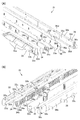
次に、上記ナビランプユニット31の概略構成について図2に基づいて説明をする。図2に示すように、ナビランプユニット31は、スロットマシン1の外装において表示窓51の周りを覆う上扉ユニット50Uの前カバー30と、複数のアウターレンズ33(第2保持部材)と、複数のインナーレンズ34と、光源となる発光ダイオード35a(以下、LEDという)を備えた複数のLED基板35(回路基板)と、LED基板35の後方を覆う後カバー36(第1保持部材)と、を備えている。
2. Schematic configuration of the navigation lamp unit Next, the schematic configuration of the navigation lamp unit 31 will be described with reference to FIG. As shown in FIG. 2, the navigation lamp unit 31 includes a front cover 30 of an upper door unit 50U that covers the periphery of the display window 51 in the exterior of the slot machine 1, a plurality of outer lenses 33 (second holding members), and a plurality of the navigation lamp units 31. The inner lens 34 of the above, a plurality of LED substrates 35 (circuit boards) provided with light emitting diodes 35a (hereinafter referred to as LEDs) as a light source, a rear cover 36 (first holding member) covering the rear of the LED substrate 35, and the like. It has.

前カバー30は、上扉ユニット50Uにおいて、表示窓51の上方部分をカバーするトップカバー部30Tと、表示窓51の側方をカバーするサイドカバー部30L,30Rと、表示窓51の下方部分をカバーするするボトムカバー部30Bと、を備えている。サイドカバー部30Lにはランプ装置77が、サイドカバー部30RにはプッシュボタンSBが取り付けられる。 In the upper door unit 50U, the front cover 30 includes a top cover portion 30T that covers the upper portion of the display window 51, side cover portions 30L and 30R that cover the sides of the display window 51, and a lower portion of the display window 51. It includes a bottom cover portion 30B to cover. A lamp device 77 is attached to the side cover portion 30L, and a push button SB is attached to the side cover portion 30R.

上記トップカバー部30Tの後方には、後カバー36が配置されて、後方からねじ32によりトップカバー部30Tに固定されている。トップカバー部30Tと後カバー36との間には、後カバー36に対向してアウターレンズ33が配置され、トップカバー部30Tに支持されている。また、後カバー36とアウターレンズ33との間には、LED基板35が配置されている。また、トップカバー部30Tは、発光部31aに対応する位置に複数の開口30aが形成されており、該開口30aを通して、アウターレンズ33に形成されているレンズ面33aが露出するように構成されている。 A rear cover 36 is arranged behind the top cover portion 30T, and is fixed to the top cover portion 30T from the rear by screws 32. An outer lens 33 is arranged between the top cover portion 30T and the rear cover 36 so as to face the rear cover 36 and is supported by the top cover portion 30T. Further, an LED substrate 35 is arranged between the rear cover 36 and the outer lens 33. Further, the top cover portion 30T is configured such that a plurality of openings 30a are formed at positions corresponding to the light emitting portions 31a, and the lens surface 33a formed on the outer lens 33 is exposed through the openings 30a. There is.

ねじ32により後カバー36がトップカバー部30Tに固定された状態において、アウターレンズ33及びLED基板35は、前後方向に僅かに(例えば0.5mm以内)移動可能に構成されている。このように構成されることにより、ナビランプユニット31は、後カバー36が固定された状態において、LED基板35に前後方向に変形するストレスを与えてしまうことを防止することができる。 The outer lens 33 and the LED substrate 35 are configured to be slightly movable (for example, within 0.5 mm) in the front-rear direction while the rear cover 36 is fixed to the top cover portion 30T by the screws 32. With this configuration, the navigation lamp unit 31 can prevent the LED substrate 35 from being stressed to be deformed in the front-rear direction when the rear cover 36 is fixed.

複数のアウターレンズ33及びアウターレンズ33とLED基板35との間に配置されている複数のインナーレンズ34は、それぞれ左右方向に1列に並べられて配置されている。アウターレンズ33及びインナーレンズ34は、透明度が高い合成樹脂で形成されており、LED基板35の前面側を覆って保護すると共に、LED35aが出力する光を屈折、収束、拡散させる等により方向を変化させ、遊技者に対してLED35aの光を効果的に見せている。 The plurality of outer lenses 33 and the plurality of inner lenses 34 arranged between the outer lens 33 and the LED substrate 35 are arranged in a row in the left-right direction. The outer lens 33 and the inner lens 34 are made of a highly transparent synthetic resin, and cover and protect the front side of the LED substrate 35, and change the direction by refracting, converging, and diffusing the light output by the LED 35a. The light of the LED 35a is effectively shown to the player.

複数(例えば2枚)のLED基板35は、前面及び後面が略並行で、前面及び後面に配線(不図示)が形成されている回路基板であり、前面にはLED35aが、後面にはLED35aに電力を供給するためのコネクタ35b(図3(B)参照)が搭載されている。LED基板35は、それぞれ左右方向が長辺となる長方形に形成されて、左右方向に並べられて配置されている。LED基板35の上下方向の幅は、アウターレンズ33の上下方向の幅と略同一であり、最左方に配置されているLED基板35の左端と最右方に配置されているLED基板35の右端との長さは、最左方に配置されているアウターレンズ33の左端と最右方に配置されているアウターレンズ33の右端との長さと、略同一であるように形成されている。 A plurality of (for example, two) LED boards 35 are circuit boards in which the front and rear surfaces are substantially parallel and wiring (not shown) is formed on the front and rear surfaces, with the LED 35a on the front surface and the LED 35a on the rear surface. A connector 35b (see FIG. 3B) for supplying electric power is mounted. The LED substrates 35 are formed in a rectangular shape having long sides in the left-right direction, and are arranged side by side in the left-right direction. The vertical width of the LED substrate 35 is substantially the same as the vertical width of the outer lens 33, and the left end of the LED substrate 35 arranged on the leftmost side and the LED substrate 35 arranged on the rightmost side. The length with the right end is formed to be substantially the same as the length between the left end of the outer lens 33 arranged on the leftmost side and the right end of the outer lens 33 arranged on the rightmost side.

後カバー36は、透明度が低い合成樹脂で形成されており、LED基板35の後面側を覆ってLED基板35を保護すると共に、LED35aから出力される光を後方に漏れにくくするように構成されている。また、後カバー36の上下方向の幅は、LED基板35の上下方向の幅と略同一であり、後カバー36の左右方向の長さは、最左方に配置されているLED基板35の左端と最右方に配置されているLED基板35の右端との長さと、略同一であるように形成されている。このように、LED基板35の上端、下端、左端及び右端(以下、上端、下端、左端及び右端をまとめて端面という)は、アウターレンズ33及び後カバー36によっては覆われないように構成されている。 The rear cover 36 is made of a synthetic resin having low transparency, and is configured to cover the rear surface side of the LED substrate 35 to protect the LED substrate 35 and to prevent light output from the LED 35a from leaking rearward. There is. Further, the vertical width of the rear cover 36 is substantially the same as the vertical width of the LED substrate 35, and the horizontal length of the rear cover 36 is the left end of the LED substrate 35 arranged on the leftmost side. Is formed so as to be substantially the same as the length of the LED substrate 35 arranged on the rightmost side and the right end of the LED substrate 35. As described above, the upper end, the lower end, the left end and the right end (hereinafter, the upper end, the lower end, the left end and the right end are collectively referred to as an end face) of the LED substrate 35 are configured so as not to be covered by the outer lens 33 and the rear cover 36. There is.

3.ナビランプユニットの詳細
次に、ナビランプユニット31において、後カバー36と、それぞれ最右方に配置されているアウターレンズ33、インナーレンズ34及びLED基板35と、の詳細について図3及び図4に基づいて説明をする。図3(A)及び(B)に示すように、後カバー36は、前方に向けて配置されている板状の後保護板36aと、後保護板36aの周縁部から前方へ延設されている後壁部36bと、を有し、後保護板36aには、ねじ32が貫通する複数のねじ孔36cが形成されている。
3. 3. Details of the Navi Lamp Unit Next, in the navigation lamp unit 31, details of the rear cover 36 and the outer lens 33, the inner lens 34, and the LED substrate 35 arranged on the far right, respectively, are shown in FIGS. 3 and 4. I will explain based on this. As shown in FIGS. 3A and 3B, the rear cover 36 extends forward from the plate-shaped rear protective plate 36a arranged toward the front and the peripheral edge of the rear protective plate 36a. The rear wall portion 36b and the rear protective plate 36a are formed with a plurality of screw holes 36c through which the screws 32 penetrate.

後壁部36bの前端には、円柱状の複数の後カバー突起部36d(第1突起部)が前方に向けて突起して設けられている。また、複数の後カバー突起部36dの前端は、略同一平面上に配置されている。後カバー36は、後保護板36aの前面から後カバー突起部36dの前端までの距離が、LED基板35の後面に搭載されているコネクタ35b等の部品の前後方向の最大長さより大きくなるように形成されている。また、後カバー突起部36dは、周囲からの突出長さが、LED基板35の後面に形成されている配線の厚さより十分に長く形成されていると共に、少なくとも3つの後カバー突起部36dの前端が、LED基板35の後面(一方の面)の周縁部に同時に当接可能に形成されており、後カバー突起部36dがLED基板35に当接して、LED基板35の後方への移動を規制している。これにより、LED基板35の後面と後壁部36bの前端との間には、LED基板35の後面に形成されている配線の厚さより前後方向の寸法が大きな空間42が形成され(図4(A)参照)、後壁部36bの前端はLED基板35及びLED基板35の後面上に形成されている配線のいずれにも当接しないように構成される。 At the front end of the rear wall portion 36b, a plurality of columnar rear cover protrusions 36d (first protrusions) are provided so as to project forward. Further, the front ends of the plurality of rear cover protrusions 36d are arranged on substantially the same plane. In the rear cover 36, the distance from the front surface of the rear protection plate 36a to the front end of the rear cover protrusion 36d is larger than the maximum length in the front-rear direction of components such as the connector 35b mounted on the rear surface of the LED substrate 35. It is formed. Further, the rear cover protrusion 36d is formed so that the protrusion length from the periphery is sufficiently longer than the thickness of the wiring formed on the rear surface of the LED substrate 35, and the front ends of at least three rear cover protrusions 36d. Is formed so as to be able to abut on the peripheral edge of the rear surface (one surface) of the LED substrate 35 at the same time, and the rear cover protrusion 36d abuts on the LED substrate 35 to restrict the movement of the LED substrate 35 to the rear. doing. As a result, a space 42 having a size larger in the front-rear direction than the thickness of the wiring formed on the rear surface of the LED substrate 35 is formed between the rear surface of the LED substrate 35 and the front end of the rear wall portion 36b (FIG. 4 (FIG. 4). A)), the front end of the rear wall portion 36b is configured so as not to come into contact with either the LED substrate 35 or the wiring formed on the rear surface of the LED substrate 35.

LED基板35は、厚さが略一定の平板状に形成されており、前方を向くように配置されている。LED基板35は、前面及び後面に配線がエッチング等により形成されており、後面のコネクタ35bに供給された電流が配線を通じてLED35aに供給されるように構成されている。なお、以下の記載において、LED基板35の前面及び後面の、配線が形成されている範囲を配線部35g(図5(A)、(B)参照)、配線が形成されていない範囲を非配線部35h(図5(A)、(B)参照)という。後カバー突起部36dが当接可能なLED基板35の後面の範囲は非配線部35hとなっている。 The LED substrate 35 is formed in a flat plate shape having a substantially constant thickness, and is arranged so as to face forward. Wiring is formed on the front surface and the rear surface of the LED substrate 35 by etching or the like, and the current supplied to the connector 35b on the rear surface is supplied to the LED 35a through the wiring. In the following description, the range where the wiring is formed on the front surface and the rear surface of the LED substrate 35 is the wiring portion 35g (see FIGS. 5A and 5B), and the range where the wiring is not formed is non-wiring. Part 35h (see FIGS. 5A and 5B). The range of the rear surface of the LED substrate 35 to which the rear cover protrusion 36d can come into contact is the non-wiring portion 35h.

LED基板35には、LED基板35の前面と平行な方向について、LED基板35をアウターレンズ33に対して位置決めするための、円孔35cと、LED基板の上端部及び下端部にそれぞれ配置されて前後方向に延びる溝35dと、が形成されている。また、LED基板35には、LED基板35の前面と平行な方向について、LED基板35をインナーレンズ34に対して位置決めするための、円孔35e及び長孔35fが形成されている。長孔35fは、LED基板35の前面において、長手方向が円孔35eの中心と長孔35fの中心とを結ぶ直線に平行となるように形成されている。 The LED substrate 35 is provided with a circular hole 35c for positioning the LED substrate 35 with respect to the outer lens 33 in a direction parallel to the front surface of the LED substrate 35, and an upper end portion and a lower end portion of the LED substrate, respectively. A groove 35d extending in the front-rear direction is formed. Further, the LED substrate 35 is formed with a circular hole 35e and an elongated hole 35f for positioning the LED substrate 35 with respect to the inner lens 34 in a direction parallel to the front surface of the LED substrate 35. The elongated hole 35f is formed on the front surface of the LED substrate 35 so that the longitudinal direction is parallel to the straight line connecting the center of the circular hole 35e and the center of the elongated hole 35f.

アウターレンズ33は、発光部31aに対応する位置に形成されているレンズ面33aを有して、後カバー36に対向するように前方に向けて配置されている板状の前保護板33bと、前保護板33bの周縁部から後方へ延設されている前壁部33cと、を有し、トップカバー部30Tに当接することにより前方への移動及びLED基板35の前面と平行な方向への移動が規制されている。前壁部33cの後端には、円孔35c及び溝35dのそれぞれに対応する位置に配置されている円柱状のアウターレンズ支持部33dが後方に向けて突設されている。アウターレンズ支持部33dは、円孔35c及び溝35dのそれぞれに挿入されている。これにより、アウターレンズ33は、LED基板35の前面と平行な方向について、アウターレンズ33に対してLED基板35を位置決め支持している。前壁部33cの後端には、円柱状の複数のアウターレンズ突起部33e(第2突起部)が後方に向けて突設されている。また、複数のアウターレンズ突起部33eの後端は、略同一平面上に配置されている。 The outer lens 33 has a lens surface 33a formed at a position corresponding to the light emitting portion 31a, and has a plate-shaped front protective plate 33b arranged toward the front so as to face the rear cover 36. It has a front wall portion 33c extending rearward from the peripheral edge portion of the front protective plate 33b, and moves forward by abutting on the top cover portion 30T and in a direction parallel to the front surface of the LED substrate 35. Movement is restricted. At the rear end of the front wall portion 33c, a columnar outer lens support portion 33d arranged at a position corresponding to each of the circular hole 35c and the groove 35d is projected rearward. The outer lens support portion 33d is inserted into each of the circular hole 35c and the groove 35d. As a result, the outer lens 33 positions and supports the LED substrate 35 with respect to the outer lens 33 in a direction parallel to the front surface of the LED substrate 35. At the rear end of the front wall portion 33c, a plurality of columnar outer lens protrusions 33e (second protrusions) are projected rearward. Further, the rear ends of the plurality of outer lens protrusions 33e are arranged on substantially the same plane.

また、アウターレンズ突起部33eは、前壁部33cの後端からの突出長さが、LED基板35の前面に形成されている配線の厚さより十分に長く形成されていると共に、少なくとも3つのアウターレンズ突起部33eの後端が、LED基板35の前面(他方の面)の周縁部に同時に当接可能に形成されており、アウターレンズ突起部33eがLED基板35に当接して、LED基板35の後方への移動を規制している。これにより、LED基板35の前面と前壁部33cの後端との間には、LED基板35の前面に形成されている配線の厚さより前後方向の寸法が大きな空間40が形成され(図4(A)参照)、前壁部33cの後端はLED基板35及びLED基板35の前面上に形成されている配線のいずれにも当接しないように構成される。 Further, the outer lens protrusion 33e is formed so that the protrusion length from the rear end of the front wall portion 33c is sufficiently longer than the thickness of the wiring formed on the front surface of the LED substrate 35, and at least three outer lenses are formed. The rear end of the lens protrusion 33e is formed so as to be able to abut on the peripheral edge of the front surface (the other surface) of the LED substrate 35 at the same time, and the outer lens protrusion 33e abuts on the LED substrate 35 to abut the LED substrate 35. It regulates the movement of the LED to the rear. As a result, a space 40 having a size larger in the front-rear direction than the thickness of the wiring formed on the front surface of the LED substrate 35 is formed between the front surface of the LED substrate 35 and the rear end of the front wall portion 33c (FIG. 4). (See (A)), the rear end of the front wall portion 33c is configured so as not to come into contact with either the LED substrate 35 or the wiring formed on the front surface of the LED substrate 35.

また、アウターレンズ突起部33eは、LED基板35の前面に形成されている非配線部35hに当接するように配置されていると共に、LED基板35の前面に形成されている配線からは十分な距離(例えば5mm)を離して配置されており、LED基板35の前面と平行な方向における部品間の遊びや部品寸法のばらつき等があっても、配線とアウターレンズ突起部33eとが当接しないように構成されている。 Further, the outer lens protrusion 33e is arranged so as to abut the non-wiring portion 35h formed on the front surface of the LED substrate 35, and is a sufficient distance from the wiring formed on the front surface of the LED substrate 35. They are arranged apart from each other (for example, 5 mm) so that the wiring and the outer lens protrusion 33e do not come into contact with each other even if there is play between the parts in the direction parallel to the front surface of the LED substrate 35 or the component dimensions vary. It is configured in.

インナーレンズ34は、前方を向くように配置されている板状に形成されて、アウターレンズの前壁部33cの内側に収納されており、アウターレンズ33に当接することにより前方への移動が規制されている。インナーレンズ34は、前面及び後面に、LED35aが出力した光の方向を変化させるための複数の凹凸34aが形成されており、後面に、LED35aとインナーレンズ34とが当接することを防ぐための凹部34bがLED35aに対応する位置に形成されている。インナーレンズ34の後面側には、円孔35e及び長孔35fのそれぞれに対応する位置に配置されている円柱状のインナーレンズ支持部34cが後方に向けて突設されている。インナーレンズ支持部34cは、円孔35e及び長孔35fのそれぞれに挿入されている。これにより、LED基板35は、LED基板35の前面と平行な方向について、インナーレンズ34に対して位置決め支持されている。また、インナーレンズ34の後面側には、円柱状の複数のインナーレンズ突起部34dが後方に向けて突設されている。また、インナーレンズ突起部34dの後端は、略同一平面上に配置されている。 The inner lens 34 is formed in a plate shape arranged so as to face forward, is housed inside the front wall portion 33c of the outer lens, and is restricted from moving forward by abutting on the outer lens 33. Has been done. The inner lens 34 has a plurality of irregularities 34a formed on the front surface and the rear surface for changing the direction of the light output by the LED 35a, and a concave portion on the rear surface for preventing the LED 35a and the inner lens 34 from coming into contact with each other. 34b is formed at a position corresponding to the LED 35a. On the rear surface side of the inner lens 34, a columnar inner lens support portion 34c arranged at a position corresponding to each of the circular hole 35e and the elongated hole 35f is projected rearward. The inner lens support portion 34c is inserted into each of the circular hole 35e and the elongated hole 35f. As a result, the LED substrate 35 is positioned and supported with respect to the inner lens 34 in a direction parallel to the front surface of the LED substrate 35. Further, on the rear surface side of the inner lens 34, a plurality of columnar inner lens protrusions 34d are projected rearward. Further, the rear end of the inner lens protrusion 34d is arranged on substantially the same plane.

また、少なくとも3つのインナーレンズ突起部34dの前端は、LED基板35の前面に同時に当接可能で、かつインナーレンズ突起部34dは、周囲からの突出長さが、LED基板35の前面に形成されている配線の厚さより十分に長く形成されている。これにより、LED基板35の前面とインナーレンズ支持部34c及びインナーレンズ突起部34d以外の部分との間には、LED基板35の前面に形成されている配線の厚さより前後方向の寸法が大きな空間41が形成され(図4(B)参照)、インナーレンズ34は、インナーレンズ支持部34c及びインナーレンズ突起部34d以外の部分が、LED基板35及びLED基板35の後面上の配線のいずれにも当接しないように構成される。 Further, the front ends of at least three inner lens protrusions 34d can be brought into contact with the front surface of the LED substrate 35 at the same time, and the inner lens protrusions 34d have a protrusion length from the periphery formed on the front surface of the LED substrate 35. It is formed sufficiently longer than the thickness of the wiring. As a result, between the front surface of the LED substrate 35 and the portion other than the inner lens support portion 34c and the inner lens protrusion 34d, the space in the front-rear direction is larger than the thickness of the wiring formed on the front surface of the LED substrate 35. 41 is formed (see FIG. 4B), and the inner lens 34 has a portion other than the inner lens support portion 34c and the inner lens protrusion 34d on both the LED substrate 35 and the wiring on the rear surface of the LED substrate 35. It is configured so that it does not come into contact.

後カバー36は、前カバー30を介してベース部材53に固定されることで、ベース部材53に支持されている。この、後カバー36が、本実施形態における第1保持部材を構成し、アウターレンズ33が、本実施形態における第2保持部材を構成する。 The rear cover 36 is supported by the base member 53 by being fixed to the base member 53 via the front cover 30. The rear cover 36 constitutes the first holding member in the present embodiment, and the outer lens 33 constitutes the second holding member in the present embodiment.

次に、後カバー突起部36d、アウターレンズ突起部33e及びインナーレンズ突起部34dの配置について説明をする。図4(C)における断面図である図4(A)及び(B)、図4(A)における断面図である図5(A)及び(B)に示すように、後カバー突起部36dとアウターレンズ突起部33eとは、左右方向即ちLED基板35の長手方向において互いに重ならないように配置されており、後カバー突起部36dとインナーレンズ突起部34dとは、左右方向即ちLED基板35の長手方向において互いに重ならないように配置されている。従って、LED基板35の前面に交差する方向視において、後カバー突起部36dとアウターレンズ突起部33eとが、後カバー突起部36dとインナーレンズ突起部34dとが、それぞれ重ならない位置に配置されているといえる。 Next, the arrangement of the rear cover protrusion 36d, the outer lens protrusion 33e, and the inner lens protrusion 34d will be described. As shown in FIGS. 4 (A) and 4 (B), which are cross-sectional views in FIG. 4 (C), and FIGS. 5 (A) and 5 (B), which are cross-sectional views in FIG. 4 (A), the rear cover protrusion 36d The outer lens protrusion 33e is arranged so as not to overlap each other in the left-right direction, that is, the longitudinal direction of the LED substrate 35, and the rear cover protrusion 36d and the inner lens protrusion 34d are arranged in the left-right direction, that is, the longitudinal direction of the LED substrate 35. They are arranged so that they do not overlap each other in the direction. Therefore, in the directional view intersecting the front surface of the LED substrate 35, the rear cover protrusion 36d and the outer lens protrusion 33e are arranged at positions where the rear cover protrusion 36d and the inner lens protrusion 34d do not overlap each other. It can be said that there is.

また、LED基板35の前面において、非配線部35hは、LED基板35の前面に当接可能なアウターレンズ突起部33e及びインナーレンズ突起部34dの周囲に形成されている。LED基板35の前面と平行な方向における部品間の遊びや部品寸法のばらつき等があっても、配線部35gに形成されている配線と、アウターレンズ突起部33e及びインナーレンズ突起部34dと、が当接しないように、非配線部35hは、アウターレンズ突起部33e及びインナーレンズ突起部34dのLED基板35の前面に当接可能な面から十分な範囲(例えば周囲5mm)に形成されている。 Further, on the front surface of the LED substrate 35, the non-wiring portion 35h is formed around the outer lens protrusion 33e and the inner lens protrusion 34d that can come into contact with the front surface of the LED substrate 35. Even if there is play between parts in the direction parallel to the front surface of the LED substrate 35 or variations in component dimensions, the wiring formed in the wiring portion 35g and the outer lens protrusion 33e and the inner lens protrusion 34d are still present. The non-wiring portion 35h is formed in a sufficient range (for example, a circumference of 5 mm) from the surface of the outer lens protrusion 33e and the inner lens protrusion 34d that can be brought into contact with the front surface of the LED substrate 35 so as not to come into contact with each other.

同様に、LED基板35の後面においては、LED基板35の後面に当接可能な後カバー突起部36dの周囲に非配線部35hが形成されている。LED基板35の後面と平行な方向における部品間の遊びや部品寸法のばらつき等があっても、配線部35gに形成されている配線と、後カバー突起部36dと、が当接しないように、非配線部35hは、後カバー突起部36dのLED基板35の前面に当接可能な面から十分な範囲(例えば周囲5mm)に形成されている。このように、LED基板35の前面及び後面において、非配線部35hは、LED基板の前面及び後面に当接可能なアウターレンズ突起部33e、インナーレンズ突起部34d及び後カバー突起部36dの周囲の限られた領域に形成されて、非配線部35hを除く領域である配線部35gに配線を形成可能としている。 Similarly, on the rear surface of the LED substrate 35, a non-wiring portion 35h is formed around the rear cover protrusion 36d that can come into contact with the rear surface of the LED substrate 35. Even if there is play between parts in the direction parallel to the rear surface of the LED substrate 35 or variations in component dimensions, the wiring formed in the wiring portion 35g and the rear cover protrusion 36d do not come into contact with each other. The non-wiring portion 35h is formed in a sufficient range (for example, a circumference of 5 mm) from the surface of the rear cover protrusion 36d that can come into contact with the front surface of the LED substrate 35. As described above, on the front and rear surfaces of the LED substrate 35, the non-wiring portion 35h is around the outer lens protrusion 33e, the inner lens protrusion 34d, and the rear cover protrusion 36d that can come into contact with the front and rear surfaces of the LED substrate. It is formed in a limited region, and wiring can be formed in the wiring portion 35g, which is an region excluding the non-wiring portion 35h.

4.本実施形態のまとめ
以上のように、本実施形態のスロットマシン1は、後カバー36が、LED基板35の後面に当接可能な複数の後カバー突起部36dを有し、アウターレンズ33が、LED基板35の前面に当接可能な複数のアウターレンズ突起部33eを有しているので、LED基板35と後カバー36及びアウターレンズ33との間に、LED基板が後カバー突起部36d及びアウターレンズ突起部33eに接触しない空間42及び空間40が形成され、LED基板35が発する熱が空間42及び空間40から逃げやすいことで、LED基板35の放熱性の向上を図ることができる。
4. Summary of the present embodiment As described above, in the slot machine 1 of the present embodiment, the rear cover 36 has a plurality of rear cover protrusions 36d capable of contacting the rear surface of the LED substrate 35, and the outer lens 33 has an outer lens 33. Since the LED substrate 35 has a plurality of outer lens protrusions 33e that can come into contact with the front surface of the LED substrate 35, the LED substrate is placed between the LED substrate 35 and the rear cover 36 and the outer lens 33 with the rear cover protrusions 36d and the outer. The space 42 and the space 40 that do not come into contact with the lens protrusion 33e are formed, and the heat generated by the LED substrate 35 can easily escape from the space 42 and the space 40, so that the heat dissipation of the LED substrate 35 can be improved.

また、LED基板35に当接可能な複数のアウターレンズ突起部33eのうち少なくとも1つは複数の後カバー突起部36dのいずれにも重ならない位置に配置されているので、LED基板35の後カバー突起部36d又はアウターレンズ突起部33eが当接する部分において両面を塞いで熱が逃げにくくなることを防ぎ、LED基板35の放熱性の向上を図ることができる。 Further, since at least one of the plurality of outer lens protrusions 33e that can come into contact with the LED substrate 35 is arranged at a position that does not overlap any of the plurality of rear cover protrusions 36d, the rear cover of the LED substrate 35 is covered. It is possible to improve the heat dissipation of the LED substrate 35 by blocking both sides of the portion where the protrusion 36d or the outer lens protrusion 33e abuts to prevent heat from escaping.

また、後カバー36及びアウターレンズ33は、複数の後カバー突起部36d及びアウターレンズ突起部33eでLED基板35に当接するように構成したので、LED基板35上の非配線部35hにおいて後カバー36及びアウターレンズ33が当接する箇所を限られた領域にすることができ、LED基板35上の配線を形成可能な領域を拡大し、配線の自由度の向上を図ることができる。 Further, since the rear cover 36 and the outer lens 33 are configured so that the plurality of rear cover protrusions 36d and the outer lens protrusions 33e are in contact with the LED substrate 35, the rear cover 36 is formed in the non-wiring portion 35h on the LED substrate 35. The area where the outer lens 33 comes into contact with the outer lens 33 can be limited to a limited area, the area where wiring can be formed on the LED substrate 35 can be expanded, and the degree of freedom of wiring can be improved.

また、LED基板35は、アウターレンズ33に形成されたアウターレンズ支持部33dにより配線が形成された面と平行な方向を位置決め支持され、複数の後カバー突起部36d及びアウターレンズ突起部33eにより配線が形成された面と交差する方向を支持可能に構成されているので、後カバー36又はアウターレンズ33によりLED基板の端面を覆うようにLED基板35を支持する場合と比較して、回路基板の外寸法を大きく設計することができ、配線の自由度の向上を図ることができる。 Further, the LED substrate 35 is positioned and supported in a direction parallel to the surface on which the wiring is formed by the outer lens support portion 33d formed on the outer lens 33, and is wired by the plurality of rear cover protrusions 36d and the outer lens protrusion 33e. Since it is configured to be able to support the direction intersecting the surface on which the circuit board is formed, the circuit board has a circuit board as compared with the case where the LED substrate 35 is supported so as to cover the end surface of the LED substrate by the rear cover 36 or the outer lens 33. The outer dimensions can be designed to be large, and the degree of freedom in wiring can be improved.

5.変形例
なお、本実施形態において、スロットマシン1は、回路基板がLEDを搭載したLED基板であるように構成されているが、これに限定されない。例えば、回路基板は、主制御基板や副制御基板、可動役物に搭載されているドライバ基板等であるように構成されていてもよいし、配線を接続するための中継基板やスロットマシン1の各部に電流を供給する電源基板等であるように構成されていてもよい。
5. Modification Example In the present embodiment, the slot machine 1 is configured such that the circuit board is an LED board on which an LED is mounted, but the slot machine 1 is not limited to this. For example, the circuit board may be configured to be a main control board, a sub control board, a driver board mounted on a movable accessory, or the like, or a relay board for connecting wiring or a slot machine 1. It may be configured to be a power supply board or the like that supplies current to each part.

また、本実施形態において、スロットマシン1は、アウターレンズ突起部33eが、LED基板35の前面に交差する方向視において後カバー突起部36dと重ならない位置に配置されるように構成されているが、全てのアウターレンズ突起部33eが、LED基板35の前面に交差する方向視において後カバー突起部36dと重ならない位置に配置されるように構成されているものに限定されない。ただし、少なくとも基板の中心から最も遠いアウターレンズ突起部33e及び後カバー突起部36d同士は重ならないように配置されていることが望ましい。 Further, in the present embodiment, the slot machine 1 is configured such that the outer lens protrusion 33e is arranged at a position where the outer lens protrusion 33e does not overlap the rear cover protrusion 36d in the direction view intersecting the front surface of the LED substrate 35. The outer lens protrusions 33e are not limited to those configured so as to be arranged at positions that do not overlap the rear cover protrusions 36d in a directional view intersecting the front surface of the LED substrate 35. However, it is desirable that at least the outer lens protrusion 33e and the rear cover protrusion 36d farthest from the center of the substrate are arranged so as not to overlap each other.

また、本実施形態において、スロットマシン1は、LED基板35が前後方向に遊びを有して支持されるように構成されているが、これに限定されない。例えば、スロットマシン1は、後カバー36がLED基板35を挟み込んだ状態でアウターレンズ33に対してねじにより固定されて、LED基板35が前後方向に遊びを有しないように支持されるように構成されていてもよい。この場合においては、複数のアウターレンズ突起部33eのうち、一部のアウターレンズ突起部33eは、LED基板35の前面に交差する方向視において後カバー突起部36dと重なる位置に配置されて、LED基板35に前後方向に変形するストレスを軽減するように構成されることが望ましい。 Further, in the present embodiment, the slot machine 1 is configured such that the LED substrate 35 is supported with play in the front-rear direction, but the slot machine 1 is not limited to this. For example, the slot machine 1 is configured such that the rear cover 36 is fixed to the outer lens 33 with screws in a state where the LED substrate 35 is sandwiched, and the LED substrate 35 is supported so as not to have play in the front-rear direction. It may have been done. In this case, of the plurality of outer lens protrusions 33e, some of the outer lens protrusions 33e are arranged at positions overlapping the rear cover protrusions 36d in a directional view intersecting the front surface of the LED substrate 35, and the LEDs are used. It is desirable that the substrate 35 is configured to reduce the stress of deforming in the front-rear direction.

また、本実施形態において、スロットマシン1は、回路基板としてのLED基板35が支持部材としてのベース部材53に支持されるように構成されているが、これに限定されない。例えば、スロットマシン1は、回路基板が筐体10に支持されるように構成されていてもよいし、下扉ユニット50Lを構成する部品に支持されるように構成されていてもよい。 Further, in the present embodiment, the slot machine 1 is configured such that the LED substrate 35 as a circuit board is supported by the base member 53 as a support member, but the slot machine 1 is not limited thereto. For example, the slot machine 1 may be configured such that the circuit board is supported by the housing 10, or may be configured so as to be supported by the components constituting the lower door unit 50L.

また、本実施形態において、スロットマシン1は、LED基板35の端面がアウターレンズ33及び後カバー36によっては覆われないように構成されているが、これに限定されない。例えば、スロットマシン1は、LED基板35の端面の一部がアウターレンズ33又は後カバー36によって覆われるように構成されていてもよい。 Further, in the present embodiment, the slot machine 1 is configured so that the end surface of the LED substrate 35 is not covered by the outer lens 33 and the rear cover 36, but the slot machine 1 is not limited thereto. For example, the slot machine 1 may be configured such that a part of the end surface of the LED substrate 35 is covered by the outer lens 33 or the rear cover 36.

また、本実施形態において、スロットマシン1は、アウターレンズ33のアウターレンズ支持部33dが、LED基板35の円孔35c及び溝35dのそれぞれに挿入され、また、インナーレンズ34のインナーレンズ支持部34cが、LED基板35の円孔35e及び長孔35fのそれぞれに挿入され、LED基板35の前面と平行な方向について、LED基板35がアウターレンズ33及びインナーレンズ34に対して位置決め支持されるように構成されているが、これに限定されない。スロットマシン1は、例えば、後カバー36から前方に向けて突設されている図示しない後カバー支持部が、円孔35e及び長孔35fのそれぞれに挿入され、LED基板35の前面と平行な方向について、LED基板35が後カバー36に対して位置決め支持されるように構成されていてもよい。 Further, in the present embodiment, in the slot machine 1, the outer lens support portion 33d of the outer lens 33 is inserted into each of the circular hole 35c and the groove 35d of the LED substrate 35, and the inner lens support portion 34c of the inner lens 34 is inserted. Is inserted into each of the circular hole 35e and the elongated hole 35f of the LED substrate 35 so that the LED substrate 35 is positioned and supported with respect to the outer lens 33 and the inner lens 34 in a direction parallel to the front surface of the LED substrate 35. It is configured, but not limited to this. In the slot machine 1, for example, a rear cover support portion (not shown) projecting from the rear cover 36 toward the front is inserted into each of the circular hole 35e and the elongated hole 35f, and the direction is parallel to the front surface of the LED substrate 35. The LED substrate 35 may be configured to be positioned and supported with respect to the rear cover 36.

また、スロットマシン1は、例えば、LED基板35に円孔35cのみ又は溝35dのみが形成されて、円孔35cのみ又は溝35dのみによって、LED基板35の前面と平行な方向について、LED基板35がアウターレンズ33、インナーレンズ34、後カバー等に位置決め支持されるように構成されていてもよい。また、スロットマシン1は、例えば、LED基板35には貫通する円孔35cや溝35dの代わりに貫通しない溝や窪み等が形成され、当該溝や窪みにアウターレンズ支持部33dやインナーレンズ支持部34c、後カバー支持部等が挿入されて、LED基板35の前面と平行な方向について、LED基板35がアウターレンズ33、インナーレンズ34、後カバー等に位置決め支持されるように構成されていてもよい。 Further, in the slot machine 1, for example, only the circular hole 35c or only the groove 35d is formed in the LED substrate 35, and the LED substrate 35 is formed in the direction parallel to the front surface of the LED substrate 35 by only the circular hole 35c or the groove 35d. May be configured to be positioned and supported by the outer lens 33, the inner lens 34, the rear cover, and the like. Further, in the slot machine 1, for example, the LED substrate 35 is formed with a groove or a recess that does not penetrate instead of the circular hole 35c or the groove 35d that penetrates, and the outer lens support portion 33d or the inner lens support portion is formed in the groove or the recess. Even if the LED substrate 35 is positioned and supported by the outer lens 33, the inner lens 34, the rear cover, etc. in the direction parallel to the front surface of the LED substrate 35 by inserting the rear cover support portion, etc. 34c. good.

また、スロットマシン1は、例えば、LED基板35に円孔35c及び溝35dのいずれも形成されず、LED基板35の前面と平行な方向について、LED基板35の端面に当接可能な部品に対してLED基板35が位置決め支持されるように構成されていてもよい。具体的には、前カバー30、後カバー36、アウターレンズ33等がLED基板35の端面に当接可能な図示しない当接部を有して、LED基板35の前面と平行な方向について、LED基板35が前カバー30、後カバー36、アウターレンズ33等に位置決め支持されるように構成されていてもよい。 Further, in the slot machine 1, for example, for a component in which neither the circular hole 35c nor the groove 35d is formed in the LED substrate 35 and the slot machine 1 can come into contact with the end surface of the LED substrate 35 in a direction parallel to the front surface of the LED substrate 35. The LED substrate 35 may be configured to be positioned and supported. Specifically, the front cover 30, the rear cover 36, the outer lens 33, and the like have a contact portion (not shown) capable of contacting the end surface of the LED substrate 35, and the LED is oriented in a direction parallel to the front surface of the LED substrate 35. The substrate 35 may be configured to be positioned and supported by the front cover 30, the rear cover 36, the outer lens 33, and the like.

また、本実施形態において、スロットマシン1は、後カバー36が第1保持部材を構成し、アウターレンズ33が第2保持部材を構成しているが、これに限定されない。スロットマシン1は、第1保持部材及び第2保持部材との間に基板が配置されているように構成されるものであればよい。スロットマシン1は、例えば、アウターレンズ33が第1保持部材を構成し、後カバー36が第2保持部材を構成してもよいし、前カバー30やインナーレンズ34が第1保持部材や第2保持部材を構成してもよいし、その他の構成部品が第1保持部材や第2保持部材を構成してもよい。 Further, in the present embodiment, in the slot machine 1, the rear cover 36 constitutes the first holding member and the outer lens 33 constitutes the second holding member, but the present invention is not limited thereto. The slot machine 1 may be configured such that a substrate is arranged between the first holding member and the second holding member. In the slot machine 1, for example, the outer lens 33 may form the first holding member, the rear cover 36 may form the second holding member, and the front cover 30 and the inner lens 34 may form the first holding member or the second holding member. The holding member may be formed, or other components may form the first holding member or the second holding member.

また、本実施形態においては、遊技機の一例である、メダルを遊技媒体として用いた遊技を行うスロットマシンを例にして説明したが、本発明は、遊技球を遊技媒体として用いた遊技を行うスロットマシンや、入賞口への入球を抽選契機とした抽選が実行されるパチンコ機を含む弾球遊技機等の各種の遊技機に適用可能である。 Further, in the present embodiment, a slot machine for playing a game using a medal as a game medium, which is an example of a game machine, has been described as an example, but the present invention performs a game using a game ball as a game medium. It can be applied to various game machines such as slot machines and ball game machines including pachinko machines in which a lottery is executed when a ball is entered into a winning opening.

1 スロットマシン(遊技機)
33 アウターレンズ(第2保持部材)
33d アウターレンズ支持部(支持部)
33e アウターレンズ突起部(第2突起部)
35 LED基板(回路基板)
35c 円孔(孔)
35d 溝
36 後カバー(第1保持部材)
36d 後カバー突起部(第1突起部)
53 ベース部材(支持部材)
75 上部ランプユニット(装飾部材)
76L サイドランプユニット(装飾部材)
76R サイドランプユニット(装飾部材)
1 slot machine (game machine)
33 Outer lens (second holding member)
33d outer lens support (support)
33e Outer lens protrusion (second protrusion)
35 LED board (circuit board)
35c circular hole (hole)
35d groove 36 rear cover (first holding member)
36d Rear cover protrusion (first protrusion)
53 Base member (support member)
75 Upper lamp unit (decorative member)
76L side lamp unit (decorative member)
76R side lamp unit (decorative member)

Claims (1)

持部材を有する遊技機において、
前記支持部材に支持された第1保持部材と、
前記第1保持部材に対向して支持された第2保持部材と、
前記第1保持部材と前記第2保持部材との間に配置され、配線が形成された配線部を少なくとも片面に有すると共に配線が形成されない非配線部を両面に有した回路基板と、を備え、
前記第1保持部材は、前記両面の一方の面の非配線部に当接可能な複数の第1突起部を有し、
前記第2保持部材は、前記両面の他方の面の非配線部に当接可能な複数の第2突起部を有し、
前記第1保持部材及び前記第2保持部材の少なくとも一方は、前記回路基板を支持する支持部を有し、
前記複数の第1突起部、前記複数の第2突起部、前記支持部のうち少なくとも1つは、のいずれにも前記片面に交差する方向視において重ならない位置に配置されている、
ことを特徴とする遊技機。
In the gaming machine having a supporting lifting member,
The first holding member supported by the support member and
A second holding member supported so as to face the first holding member,
A circuit board arranged between the first holding member and the second holding member and having a wiring portion on which wiring is formed on at least one side and a non-wiring portion on both sides on which wiring is not formed is provided.
The first holding member has a plurality of first protrusions that can come into contact with non-wiring portions on one of the two surfaces.
The second holding member has a plurality of second protrusions capable of contacting the non-wiring portions on the other side of both sides.
At least one of the first holding member and the second holding member has a support portion for supporting the circuit board.
At least one of the plurality of first protrusions, the plurality of second protrusions , and the support portion is arranged at a position where it does not overlap with any of the other portions in a directional view intersecting the one side.
A gaming machine characterized by that.
JP2017221311A 2017-11-16 2017-11-16 Pachinko machine Active JP6947397B2 (en)

Priority Applications (1)

Application Number Priority Date Filing Date Title
JP2017221311A JP6947397B2 (en) 2017-11-16 2017-11-16 Pachinko machine

Applications Claiming Priority (1)

Application Number Priority Date Filing Date Title
JP2017221311A JP6947397B2 (en) 2017-11-16 2017-11-16 Pachinko machine

Publications (2)

Publication Number Publication Date
JP2019088706A JP2019088706A (en) 2019-06-13
JP6947397B2 true JP6947397B2 (en) 2021-10-13

Family

ID=66835424

Family Applications (1)

Application Number Title Priority Date Filing Date
JP2017221311A Active JP6947397B2 (en) 2017-11-16 2017-11-16 Pachinko machine

Country Status (1)

Country Link
JP (1) JP6947397B2 (en)

Family Cites Families (4)

* Cited by examiner, † Cited by third party
Publication number Priority date Publication date Assignee Title
JP2003230724A (en) * 2002-02-07 2003-08-19 Sanyo Product Co Ltd Game machine
JP5085413B2 (en) * 2008-04-30 2012-11-28 株式会社ニューギン Game machine
JP2016144506A (en) * 2015-02-06 2016-08-12 株式会社藤商事 Game machine
JP2017099779A (en) * 2015-12-03 2017-06-08 株式会社三洋物産 Game machine

Also Published As

Publication number Publication date
JP2019088706A (en) 2019-06-13

Similar Documents

Publication Publication Date Title
JP5848658B2 (en) Game machine
JP2007307003A (en) Game machine
JP2013233295A (en) Pachinko machine
JP2005348927A (en) Game machine
JP5808452B2 (en) Game machine
JP2007307186A (en) Game machine
JP2013106704A (en) Game machine
JP6947397B2 (en) Pachinko machine
JP2019030438A (en) Game machine
JP4150358B2 (en) Game machine
JP6263101B2 (en) Game machine
JP2019154966A (en) Game machine
JP7112841B2 (en) game machine
JP6962561B2 (en) Pachinko machine
JP2018102407A (en) Game machine
JP7029790B2 (en) Pachinko machine
JP2004049411A (en) Game machine
JP2015156971A (en) Game machine
JP2024088855A (en) Game machine
JP2015077224A (en) Game machine
JP2024088852A (en) Game machine
JP4141417B2 (en) Game machine
JP2024088853A (en) Game machine
JP2024088854A (en) Game machine
JP6133948B2 (en) Game machine

Legal Events

Date Code Title Description
RD02 Notification of acceptance of power of attorney

Free format text: JAPANESE INTERMEDIATE CODE: A7422

Effective date: 20200205

RD04 Notification of resignation of power of attorney

Free format text: JAPANESE INTERMEDIATE CODE: A7424

Effective date: 20200206

A621 Written request for application examination

Free format text: JAPANESE INTERMEDIATE CODE: A621

Effective date: 20200817

A977 Report on retrieval

Free format text: JAPANESE INTERMEDIATE CODE: A971007

Effective date: 20210520

A131 Notification of reasons for refusal

Free format text: JAPANESE INTERMEDIATE CODE: A131

Effective date: 20210622

A521 Request for written amendment filed

Free format text: JAPANESE INTERMEDIATE CODE: A523

Effective date: 20210803

TRDD Decision of grant or rejection written
A01 Written decision to grant a patent or to grant a registration (utility model)

Free format text: JAPANESE INTERMEDIATE CODE: A01

Effective date: 20210831

A61 First payment of annual fees (during grant procedure)

Free format text: JAPANESE INTERMEDIATE CODE: A61

Effective date: 20210909

R150 Certificate of patent or registration of utility model

Ref document number: 6947397

Country of ref document: JP

Free format text: JAPANESE INTERMEDIATE CODE: R150

R250 Receipt of annual fees

Free format text: JAPANESE INTERMEDIATE CODE: R250