JP6944112B2 - Filament, structure and its manufacturing method - Google Patents
Filament, structure and its manufacturing method Download PDFInfo
- Publication number
- JP6944112B2 JP6944112B2 JP2017215512A JP2017215512A JP6944112B2 JP 6944112 B2 JP6944112 B2 JP 6944112B2 JP 2017215512 A JP2017215512 A JP 2017215512A JP 2017215512 A JP2017215512 A JP 2017215512A JP 6944112 B2 JP6944112 B2 JP 6944112B2
- Authority
- JP
- Japan
- Prior art keywords
- core material
- coating layer
- filament
- adherend
- shaping pattern
- Prior art date
- Legal status (The legal status is an assumption and is not a legal conclusion. Google has not performed a legal analysis and makes no representation as to the accuracy of the status listed.)
- Active
Links
Images


Classifications
-
- B—PERFORMING OPERATIONS; TRANSPORTING
- B29—WORKING OF PLASTICS; WORKING OF SUBSTANCES IN A PLASTIC STATE IN GENERAL
- B29B—PREPARATION OR PRETREATMENT OF THE MATERIAL TO BE SHAPED; MAKING GRANULES OR PREFORMS; RECOVERY OF PLASTICS OR OTHER CONSTITUENTS OF WASTE MATERIAL CONTAINING PLASTICS
- B29B11/00—Making preforms
- B29B11/06—Making preforms by moulding the material
- B29B11/10—Extrusion moulding
-
- B—PERFORMING OPERATIONS; TRANSPORTING
- B29—WORKING OF PLASTICS; WORKING OF SUBSTANCES IN A PLASTIC STATE IN GENERAL
- B29B—PREPARATION OR PRETREATMENT OF THE MATERIAL TO BE SHAPED; MAKING GRANULES OR PREFORMS; RECOVERY OF PLASTICS OR OTHER CONSTITUENTS OF WASTE MATERIAL CONTAINING PLASTICS
- B29B15/00—Pretreatment of the material to be shaped, not covered by groups B29B7/00 - B29B13/00
- B29B15/08—Pretreatment of the material to be shaped, not covered by groups B29B7/00 - B29B13/00 of reinforcements or fillers
- B29B15/10—Coating or impregnating independently of the moulding or shaping step
- B29B15/12—Coating or impregnating independently of the moulding or shaping step of reinforcements of indefinite length
- B29B15/122—Coating or impregnating independently of the moulding or shaping step of reinforcements of indefinite length with a matrix in liquid form, e.g. as melt, solution or latex
-
- B—PERFORMING OPERATIONS; TRANSPORTING
- B29—WORKING OF PLASTICS; WORKING OF SUBSTANCES IN A PLASTIC STATE IN GENERAL
- B29C—SHAPING OR JOINING OF PLASTICS; SHAPING OF MATERIAL IN A PLASTIC STATE, NOT OTHERWISE PROVIDED FOR; AFTER-TREATMENT OF THE SHAPED PRODUCTS, e.g. REPAIRING
- B29C64/00—Additive manufacturing, i.e. manufacturing of three-dimensional [3D] objects by additive deposition, additive agglomeration or additive layering, e.g. by 3D printing, stereolithography or selective laser sintering
- B29C64/10—Processes of additive manufacturing
- B29C64/106—Processes of additive manufacturing using only liquids or viscous materials, e.g. depositing a continuous bead of viscous material
- B29C64/118—Processes of additive manufacturing using only liquids or viscous materials, e.g. depositing a continuous bead of viscous material using filamentary material being melted, e.g. fused deposition modelling [FDM]
-
- B—PERFORMING OPERATIONS; TRANSPORTING
- B33—ADDITIVE MANUFACTURING TECHNOLOGY
- B33Y—ADDITIVE MANUFACTURING, i.e. MANUFACTURING OF THREE-DIMENSIONAL [3-D] OBJECTS BY ADDITIVE DEPOSITION, ADDITIVE AGGLOMERATION OR ADDITIVE LAYERING, e.g. BY 3-D PRINTING, STEREOLITHOGRAPHY OR SELECTIVE LASER SINTERING
- B33Y70/00—Materials specially adapted for additive manufacturing
- B33Y70/10—Composites of different types of material, e.g. mixtures of ceramics and polymers or mixtures of metals and biomaterials
-
- D—TEXTILES; PAPER
- D01—NATURAL OR MAN-MADE THREADS OR FIBRES; SPINNING
- D01D—MECHANICAL METHODS OR APPARATUS IN THE MANUFACTURE OF ARTIFICIAL FILAMENTS, THREADS, FIBRES, BRISTLES OR RIBBONS
- D01D5/00—Formation of filaments, threads, or the like
- D01D5/28—Formation of filaments, threads, or the like while mixing different spinning solutions or melts during the spinning operation; Spinnerette packs therefor
- D01D5/30—Conjugate filaments; Spinnerette packs therefor
- D01D5/34—Core-skin structure; Spinnerette packs therefor
-
- D—TEXTILES; PAPER
- D01—NATURAL OR MAN-MADE THREADS OR FIBRES; SPINNING
- D01F—CHEMICAL FEATURES IN THE MANUFACTURE OF ARTIFICIAL FILAMENTS, THREADS, FIBRES, BRISTLES OR RIBBONS; APPARATUS SPECIALLY ADAPTED FOR THE MANUFACTURE OF CARBON FILAMENTS
- D01F8/00—Conjugated, i.e. bi- or multicomponent, artificial filaments or the like; Manufacture thereof
- D01F8/04—Conjugated, i.e. bi- or multicomponent, artificial filaments or the like; Manufacture thereof from synthetic polymers
-
- B—PERFORMING OPERATIONS; TRANSPORTING
- B33—ADDITIVE MANUFACTURING TECHNOLOGY
- B33Y—ADDITIVE MANUFACTURING, i.e. MANUFACTURING OF THREE-DIMENSIONAL [3-D] OBJECTS BY ADDITIVE DEPOSITION, ADDITIVE AGGLOMERATION OR ADDITIVE LAYERING, e.g. BY 3-D PRINTING, STEREOLITHOGRAPHY OR SELECTIVE LASER SINTERING
- B33Y10/00—Processes of additive manufacturing
-
- B—PERFORMING OPERATIONS; TRANSPORTING
- B33—ADDITIVE MANUFACTURING TECHNOLOGY
- B33Y—ADDITIVE MANUFACTURING, i.e. MANUFACTURING OF THREE-DIMENSIONAL [3-D] OBJECTS BY ADDITIVE DEPOSITION, ADDITIVE AGGLOMERATION OR ADDITIVE LAYERING, e.g. BY 3-D PRINTING, STEREOLITHOGRAPHY OR SELECTIVE LASER SINTERING
- B33Y80/00—Products made by additive manufacturing
Description
本発明は、フィラメント、構造体及びその製造方法に関する。 The present invention relates to filaments, structures and methods for producing the same.
特許文献1には、使用温度付近にガラス転移温度を設定したウレタンエラストマーを用いた形状記憶成形体が開示されている。形状記憶成形体の例として、ギブス等が挙げられている。
特許文献1では、ウレタンエラストマー自体をギブスの材料として用いているので、他の材料を用いることができない。
In
本発明はこのような事情に鑑みてなされたものであり、任意の材料の被着体に形状記憶特性を発揮させることを可能にするフィラメントを提供するものである。 The present invention has been made in view of such circumstances, and provides a filament that enables an adherend of an arbitrary material to exhibit shape memory characteristics.
本発明によれば、線状の芯材と、前記芯材を被覆する被覆層を備える、フィラメントであって、前記芯材は、形状記憶材料で形成され、前記被覆層は、前記芯材とは異なる材料で形成される、フィラメントが提供される。 According to the present invention, a filament comprising a linear core material and a coating layer covering the core material, the core material being formed of a shape memory material, and the coating layer being the core material. Filaments are provided, which are made of different materials.
本発明者は、被着体の形状を変化させるための賦形パターンを、形状記憶材料で形成されたフィラメントを用いて形成することによって、任意の材料の被着体に形状記憶特性を発揮させることができることに気づいた。一方、形状記憶材料と被着体の溶着性が良好でない場合には、フィラメントを被着体に溶着させることが容易ではないという課題に気づいた。そして、形状記憶材料で形成された芯材が被覆層で被覆された構成のフィラメントを用いれば、被着体との溶着性に優れた材料を被覆層の材料として選択することによって、任意の材料の被着体とフィラメントの溶着性を良好にすることができることに気づき、本発明の完成に到った。本発明のフィラメントを用いて、被着体の形状を変化させるための賦形パターンを被着体に形成することによって、任意の被着体に形状記憶特性を発揮させることが可能になる。 The present inventor makes an adherend of any material exhibit shape memory characteristics by forming a shaping pattern for changing the shape of the adherend using a filament formed of a shape memory material. I realized that I could do it. On the other hand, I have noticed a problem that it is not easy to weld the filament to the adherend when the weldability between the shape memory material and the adherend is not good. Then, by using a filament having a core material formed of a shape memory material coated with a coating layer, an arbitrary material can be selected by selecting a material having excellent weldability to an adherend as the material of the coating layer. It was noticed that the weldability between the adherend and the filament could be improved, and the present invention was completed. By using the filament of the present invention to form a shaping pattern on the adherend for changing the shape of the adherend, it is possible to make any adherend exhibit shape memory characteristics.
以下、本発明の種々の実施形態を例示する。以下に示す実施形態は互いに組み合わせ可能である。 Hereinafter, various embodiments of the present invention will be illustrated. The embodiments shown below can be combined with each other.
好ましくは、前記記載のフィラメントであって、前記芯材の材料が形状記憶ポリマーであり、前記被覆層の材料が熱可塑性樹脂である、フィラメントである。 Preferably, it is the filament described above, wherein the material of the core material is a shape memory polymer and the material of the coating layer is a thermoplastic resin.
好ましくは、被着体と、前記被着体の形状を変化させるための賦形パターンを備える、構造体であって、前記賦形パターンは、前記記載のフィラメントによって形成され、前記フィラメントの被覆層が前記被着体に溶着されている、構造体である。
好ましくは、前記記載の構造体であって、前記被覆層の材料は、前記芯材の材料よりも前記被着体に溶着されやすい材料である、構造体である。
好ましくは、前記記載の構造体であって、前記被着体の表面の材料のSP値をSPbase、前記被覆層の材料のSP値をSPcover、前記芯材の材料のSP値をSPcoreとし、ΔSPcoverとΔSPcoreを式(1)〜(2)で定義すると、式(3)の関係が成り立つ、構造体である。
ΔSPcover=|SPcover−SPbase| (1)
ΔSPcore=|SPcore−SPbase| (2)
ΔSPcover<ΔSPcore (3)
好ましくは、前記記載の構造体であって、式(4)の関係が成り立つ、構造体である。
ΔSPcover≦1.3 (4)
Preferably, it is a structure comprising an adherend and a shaping pattern for changing the shape of the adherend, wherein the shaping pattern is formed by the filament described above and is a coating layer of the filament. Is a structure welded to the adherend.
Preferably, the structure described above is a structure in which the material of the coating layer is a material that is more easily welded to the adherend than the material of the core material.
Preferably, in the structure described above, the SP value of the material on the surface of the adherend is SPbase, the SP value of the material of the coating layer is SPcover, the SP value of the material of the core material is SPcore, and ΔSPcover. When ΔSPcore and ΔSPcore are defined by the equations (1) and (2), it is a structure in which the relationship of the equation (3) holds.
ΔSPcover = | SPcover-SPbase | (1)
ΔSPcore = | SPcore-SPbase | (2)
ΔSPcover <ΔSPcore (3)
Preferably, it is the structure described above, wherein the relationship of the formula (4) holds.
ΔSPcover ≤ 1.3 (4)
好ましくは、熱溶融方式の3Dプリンタを用いた構造体の製造方法であって、被着体の形状を変化させるための賦形パターンを形成する賦形パターン形成工程を備え、前記賦形パターン形成工程では、被覆層が芯材を被覆するように前記被覆層及び前記芯材をヘッドから溶融押し出しし、前記被覆層を前記被着体に溶着させることによって前記賦形パターンを形成し、前記芯材は、形状記憶ポリマーで形成され、前記被覆層は、前記芯材とは異なる熱可塑性樹脂で形成される、方法である。
好ましくは、前記記載の方法であって、前記賦形パターン形成工程では、前記記載のフィラメントを前記ヘッドに挿入し、前記被覆層が前記芯材を被覆した状態で前記フィラメントを前記ヘッドから溶融押し出しする、方法である。
Preferably, it is a method for manufacturing a structure using a thermal melting type 3D printer, comprising a shaping pattern forming step of forming a shaping pattern for changing the shape of an adherend, and forming the shaping pattern. In the step, the coating layer and the core material are melt-extruded from the head so that the coating layer covers the core material, and the coating layer is welded to the adherend to form the shaping pattern, and the core is formed. The material is a method in which the material is formed of a shape memory polymer and the coating layer is formed of a thermoplastic resin different from the core material.
Preferably, in the above-described method, in the shaping pattern forming step, the filament described above is inserted into the head, and the filament is melt-extruded from the head with the coating layer covering the core material. Is the way to do it.
以下、本発明の実施形態について説明する。以下に示す実施形態中で示した各種特徴事項は、互いに組み合わせ可能である。また、各特徴について独立して発明が成立する。 Hereinafter, embodiments of the present invention will be described. The various features shown in the embodiments shown below can be combined with each other. In addition, the invention is independently established for each feature.
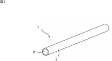
1.フィラメント1の構成及び製造方法
図1に示すように、本発明の一実施形態のフィラメント1は、線状の芯材2と、芯材2を被覆する被覆層3を備える。芯材2が線状であるために、フィラメント1も線状になっている。
1. 1. Configuration and Manufacturing Method of
芯材2は、形状記憶材料で形成される。形状記憶材料は、形状記憶特性を有する材料であり、合金、ポリマーなどで構成される。形状記憶特性とは、所定の回復温度以上に加熱することによって弾性によって原形状に復帰する特性を有する。回復温度は、材料ごとに定まる温度であり、例えば0〜100℃であり、好ましくは、25〜80℃であり、具体的には例えば、0、5、10、15、20、25、30、35、40、45、50、55、60、65、70、75、80、85、90、95、100℃であり、ここで例示した数値の何れか2つの間の範囲内であってもよい。
The
形状記憶材料が形状記憶合金である場合、回復温度は、変態点である。形状記憶合金は、変態点未満の温度で原形状から二次形状に変化させると、変態点未満では二次形状が維持され、形状記憶合金を変態点以上に加熱すると弾性によって原形状に復帰する。原形状は、例えば、形状記憶合金を所望の形状に固定した状態で熱処理(例:400〜500℃での熱処理)を行うことによって設定することができる。形状記憶合金としては、NiTi合金が例示される。 When the shape memory material is a shape memory alloy, the recovery temperature is the transformation point. When the shape memory alloy is changed from the original shape to the secondary shape at a temperature below the transformation point, the secondary shape is maintained below the transformation point, and when the shape memory alloy is heated above the transformation point, it returns to the original shape by elasticity. .. The original shape can be set, for example, by performing a heat treatment (eg, heat treatment at 400 to 500 ° C.) in a state where the shape memory alloy is fixed in a desired shape. Examples of shape memory alloys include NiTi alloys.
形状記憶材料が形状記憶ポリマーである場合、回復温度は、ガラス転移温度(Tg)である。形状記憶ポリマーは、Tg以上の温度で外力を加えて二次形状に賦形し、外力を維持したままTg未満の温度に冷却すると、二次形状が固定される。Tg未満の温度では、外力を取り除いても原形状に復帰しない。一方、二次形状が付された形状記憶ポリマーをTg以上の温度に加熱し、外力を加えない状態にすると、弾性によって原形状に復帰する。原形状は、例えば形状記憶ポリマーを溶融させて所望の形状に成形することによって設定することができる。形状記憶ポリマーとしては、ゴム弾性を有するポリマーが挙げられ、例えば、ポリノルボルネン、トランスポリイソプレン、スチレン−ブタジエン共重合体、ポリウレタンなどが挙げられる。 When the shape memory material is a shape memory polymer, the recovery temperature is the glass transition temperature (Tg). The shape memory polymer is shaped into a secondary shape by applying an external force at a temperature of Tg or higher, and when cooled to a temperature lower than Tg while maintaining the external force, the secondary shape is fixed. At a temperature lower than Tg, the original shape is not restored even if the external force is removed. On the other hand, when the shape memory polymer having a secondary shape is heated to a temperature of Tg or more and no external force is applied, the shape memory polymer is restored to its original shape by elasticity. The original shape can be set, for example, by melting a shape memory polymer and molding it into a desired shape. Examples of the shape memory polymer include polymers having rubber elasticity, and examples thereof include polynorbornene, transpolyisoprene, styrene-butadiene copolymer, and polyurethane.
被覆層3は、芯材2とは異なる材料で形成される。被覆層3の材料は、特に限定されないが、ポリエチレンやポリプロピレンなどのポリオレフィン、PETなどのポリエステル、ポリウレタンなどが挙げられる。
The
被覆層3の材料として、フィラメント1を溶着させる被着体4(図2を参照)との親和性が高い材料が好ましい。この場合、芯材2の材料に関わらず、フィラメント1を被着体4に溶着させることができる。例えば、被着体4がPETで形成され、芯材2がポリウレタンである場合、被覆層3の材料として、PETを選択する。この場合、被着体4と被覆層3の溶着性が極めて良好になる。
As the material of the
フィラメント1の直径は、例えば0.5〜3mmであり、好ましくは、1.75〜3mmであり、具体的には例えば、0.5、1、1.5、1.75、2、2.5、3mmであり、ここで例示した数値の何れか2つの間の範囲内であってもよい。フィラメント1の半径をRfilとし、芯材2の半径をRcoreとすると、Rcore/Rfilは、0.6〜0.99が好ましく、0.8〜0.95がさらに好ましく、具体的には例えば、0.6、0.65、0.7、0.75、0.8、0.85、0.9、0.92、0.95、0.99であり、ここで例示した数値の何れか2つの間の範囲内であってもよい。
The diameter of the
フィラメント1は、芯材2の材料と被覆層3の材料を多層押出することによって形成することができる。
The
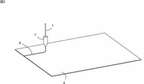
2.構造体5の構成及び製造方法
図2〜図6に示すように、本発明の一実施形態の構造体5は、被着体4と、被着体4の形状を変化させるための賦形パターン6を備える。賦形パターン6は、上記のフィラメント1によって形成されており、フィラメント1の被覆層3が被着体4に溶着されている。
2. Configuration and Manufacturing Method of
被覆層3の材料は、芯材2の材料よりも被着体4に溶着されやすい材料である。このような材料で芯材2を被覆することによって被着体4へのフィラメント1の溶着性が向上する。
The material of the
また、ハンセン溶解度パラメータ(以下、SP値)で表現すれば、被着体4の表面の材料のSP値をSPbase、被覆層3の材料のSP値をSPcover、芯材2の材料のSP値をSPcoreとし、ΔSPcoverとΔSPcoreを式(1)〜(2)で定義すると、式(3)の関係が成り立つことが好ましい。つまり、被着体4と被覆層3のSP値の差の絶対値が、被着体4と芯材2のSP値の差の絶対値よりも小さいことが好ましい。
Further, expressed by the Hansen solubility parameter (hereinafter referred to as SP value), the SP value of the material on the surface of the
このような材料で芯材2を被覆することによって被着体4へのフィラメント1の溶着性が向上する。ΔSPcore−ΔSPcoverの値は、0.1以上が好ましく、例えば0.1〜10であり、具体的には例えば、0.1、0.2、0.3、0.4、0.5、0.6、0.7、0.8、0.9、1、2、3、4、5、6、7、8、9、10であり、ここで例示した数値の何れか1つの値以上、又は2つの間の範囲内であってもよい。
By coating the
ΔSPcover=|SPcover−SPbase| (1)
ΔSPcore=|SPcore−SPbase| (2)
ΔSPcover<ΔSPcore (3)
ΔSPcover = | SPcover-SPbase | (1)
ΔSPcore = | SPcore-SPbase | (2)
ΔSPcover <ΔSPcore (3)
さらに、式(4)の関係が成り立つことが好ましい。つまり、被着体4と被覆層3のSP値の差の絶対値が1.3以下であることが好ましい。この場合、被覆層3が被着体4に強固に溶着される。ΔSPcoverは、1.0以下が好ましく、0.5以下がさらに好ましく、具体的には例えば、0、0.1、0.2、0.3、0.4、0.5、0.6、0.7、0.8、0.9、1、1.1、1.2、1.3であり、ここで例示した数値の何れか2つの間の範囲内であってもよい。被着体4の表面と被覆層3は、同じ材料で形成されることが好ましい。
ΔSPcover≦1.3 (4)
Further, it is preferable that the relationship of the equation (4) holds. That is, it is preferable that the absolute value of the difference between the SP values of the
ΔSPcover ≤ 1.3 (4)
賦形パターン6の形成方法は、特に限定されず、形状記憶材料の種類に応じて適切な方法が適宜選択される。例えば、芯材2の材料が形状記憶ポリマーであり、被覆層3の材料が熱可塑性樹脂である場合には、賦形パターン6は、熱溶融方式の3Dプリンタを用いて形成することができる。一例では、図2に示すように、フィラメント1をヘッド7に挿入し、フィラメント1を被覆層3が芯材2を被覆した状態でヘッド7から溶融押し出しし、被覆層3を被着体4に溶着させることによって賦形パターン6を形成することができる。この方法によれば、賦形パターン6を容易に形成することが可能である。ヘッド7に挿入するフィラメント1の半径をRbefore、ヘッド7から押し出されたフィラメント1の半径をRafterとすると、Rafter/Rbeforeは、0.1〜1が好ましく、具体的には例えば、0.1、0.2、0.3、0.4、0.5、0.6、0.7、0.8、0.9、1であり、ここで例示した数値の何れか2つの間の範囲内であってもよい。賦形パターン6の精度を高めるには、Rafterを小さくすることが好ましいが、Rafterを小さくすると、その分だけ被覆層3が薄くなって被着体4への溶着性が悪化する。Rafterは、例えば0.1〜0.5mmであり、具体的には例えば、0.1、0.2、0.3、0.4、0.5mmであり、ここで例示した数値の何れか2つの間の範囲内であってもよい。
The method for forming the
ヘッド7の先端と被着体4の間の距離は、例えば0.1〜1mmであり、具体的には例えば、0.1、0.2、0.3、0.4、0.5、0.6、0.7、0.8、0.9、1mmであり、ここで例示した数値の何れか2つの間の範囲内であってもよい。
The distance between the tip of the
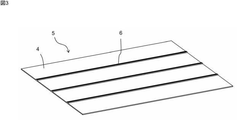
賦形パターン6は、1本のフィラメント1で構成してもよいが、図3〜図4に示すように、複数(ここでは5本)のフィラメント1を幅方向に溶着して構成してもよい。複数のフィラメント1は、被覆層3で互いに溶着されるので、溶着強度が高い。賦形パターン6を構成するフィラメント1の幅方向の本数は、例えば、1〜30本であり、具体的には例えば、1、5、10、15、20、25、30本であり、ここで例示した数値の何れか2つの間の範囲内であってもよい。
The
また、図3〜図4では、1層のフィラメント1で賦形パターン6を構成しているが、図5に示すように、複数層のフィラメント1で賦形パターン6を構成してもよい。複数層のフィラメント1は、図5Aに示すように、下層の2本の芯材2の間に、その上の層の芯材2が配置されるように構成してもよく、図5Bに示すように、下層の芯材2の上に、その上の層の芯材2が配置されるように構成してもよい。賦形パターン6を構成するフィラメント1の層数数は、例えば、1〜30層であり、具体的には例えば、1、3、5、10、15、20、25、30層であり、ここで例示した数値の何れか2つの間の範囲内であってもよい。
Further, in FIGS. 3 to 4, the
本実施形態では、被着体4は、織布、不織布、フィルムなどのシート状である。被着体4の材料は、特に限定されないが、ポリエチレンやポリプロピレンなどのポリオレフィン、PETなどのポリエステル、ポリウレタン、フッ素樹脂などが挙げられる。被着体4は、綿、麻、絹、羊毛などの天然繊維で形成されていてもよい。
In the present embodiment, the
賦形パターン6は、被着体4の片面にのみ設けてもよく、両面に設けてもよい。被着体4の表面積全体に対する、賦形パターン6が溶着されている領域の面積の割合は、1〜80%が好ましく、10〜50%が好ましく、具体的には例えば、1、5、10、15、20、25、30、35、40、45、50、55、60、65、70、75、80%であり、ここで例示した数値の何れか2つの間の範囲内であってもよい。
The
3.構造体5の使用方法
ここで、芯材2の材料が形状記憶ポリマー(Tg:55℃)である場合を例に挙げて、構造体5の使用方法について説明する。
3. 3. How to Use the
図2〜図3に示すように、被着体4を平坦にした状態で直線状の賦形パターン6を形成すると、図3の状態で原形状となる。賦形パターン6がTg未満の温度である状態では、形状記憶ポリマーの弾性率が大きい(変形しにくい)ので、賦形パターン6が容易には変形せず、被着体4の形状が平坦のまま維持される。
As shown in FIGS. 2 to 3, when the
次に、賦形パターン6を加熱してTg以上の温度にすると、形状記憶ポリマーの弾性率が大幅に低減されて賦形パターン6を自由に変形させて二次形状にすることができるようになる。例えば、図6に示すように、賦形パターン6を波板状に変形させ、その形状を維持したまま賦形パターン6をTg未満の温度にまで冷却すると、その形状が維持される。賦形パターン6は被着体4に溶着されているので、被着体4の形状も波板状になる。
Next, when the
次に、賦形パターン6を加熱してTg以上の温度にして、外力を加えないでいると、賦形パターン6が弾性によって原形状(直線形状)に復帰して、図3の状態になり、被着体4も平坦な状態に復帰する。
Next, when the
このように、構造体5では、形状記憶特性を有する賦形パターン6が被着体4に溶着されているので、被着体4にも形状記憶特性を発揮させることができる。
As described above, in the
本実施形態では、被着体4を平坦にする状態が賦形パターン6の原形状になっているが、被着体4を筒状や折れ曲がり形状などの立体形状にする状態を賦形パターン6の原形状にしてもよい。また、本実施形態では、賦形パターン6は、直線状であるが、曲線状、ジグザグ形状、格子形状などの任意の形状にすることができる。
In the present embodiment, the state in which the
構造体5の具体例としては、例えば、衣服、テント、ヨットの帆、シートの座面、シューズなどの物品が挙げられる。ユーザーが既製品の形状に満足できない場合には、これらの物品を自分の好みに合わせて変形させることができる。そして、自分好みの形状が不要になったときには、これらの物品を回復温度以上の温度に加熱するだけで、元の形状に戻すことができる。
Specific examples of the
4.その他実施形態
・上記実施形態では、フィラメント1をヘッド7に挿入して、賦形パターン形成を行ったが、フィラメント1を用いずに、芯材2の材料と、被覆層3の材料を別々に溶融してヘッド7内で合流させ、被覆層3が芯材2を被覆するように被覆層3及び芯材2をヘッド7から溶融押し出ししてフィラメント1と同様の多層構造を形成するようにしてもよい。この場合、芯材2の材料と被覆層3の材料は、それぞれ、線状であってもよく、ペレット状などの別の形態であってもよい。
・芯材2には、セルロースナノファイバーなどのフィラーを配合してもよい。
4. Other Embodiments-In the above embodiment, the
-The
1 :フィラメント
2 :芯材
3 :被覆層
4 :被着体
5 :構造体
6 :賦形パターン
7 :ヘッド
1: Filament 2: Core material 3: Coating layer 4: Adhesion 5: Structure 6: Shape pattern 7: Head
Claims (8)
前記芯材は、全体が形状記憶材料で形成され、
前記被覆層は、前記芯材とは異なる材料で形成され、
前記フィラメントは、直径が0.5〜3mmである、フィラメント。 A filament comprising a linear core material and a coating layer covering the core material.
The core material is entirely made of a shape memory material.
The coating layer is formed of a material different from that of the core material, and is formed of a material different from that of the core material .
The filament has a diameter of Ru 0.5~3mm der filament.
前記芯材の材料が形状記憶ポリマーであり、
前記被覆層の材料が熱可塑性樹脂である、フィラメント。 The filament according to claim 1.
The material of the core material is a shape memory polymer,
A filament in which the material of the coating layer is a thermoplastic resin.
前記賦形パターンは、フィラメントによって形成され、
前記フィラメントは、線状の芯材と、前記芯材を被覆する被覆層を備え、
前記芯材は、形状記憶材料で形成され、
前記被覆層は、前記芯材とは異なる材料で形成され、
前記フィラメントの被覆層が前記被着体に溶着されている、構造体。 A structure comprising an adherend and a shaping pattern for changing the shape of the adherend.
The shaping pattern is formed by off Iramento,
The filament includes a linear core material and a coating layer that covers the core material.
The core material is made of a shape memory material and is made of a shape memory material.
The coating layer is formed of a material different from that of the core material, and is formed of a material different from that of the core material.
A structure in which a coating layer of the filament is welded to the adherend.
前記被覆層の材料は、前記芯材の材料よりも前記被着体に溶着されやすい材料である、構造体。 The structure according to claim 3.
A structure in which the material of the coating layer is a material that is more easily welded to the adherend than the material of the core material.
前記被着体の表面の材料のSP値をSPbase、前記被覆層の材料のSP値をSPcover、前記芯材の材料のSP値をSPcoreとし、
ΔSPcoverとΔSPcoreを式(1)〜(2)で定義すると、式(3)の関係が成り立つ、構造体。
ΔSPcover=|SPcover−SPbase| (1)
ΔSPcore=|SPcore−SPbase| (2)
ΔSPcover<ΔSPcore (3) The structure according to claim 3 or 4.
The SP value of the material on the surface of the adherend was SPbase, the SP value of the material of the coating layer was SPcover, and the SP value of the material of the core material was SPcore.
A structure in which the relationship of the equation (3) holds when ΔSPcover and ΔSPcore are defined by the equations (1) and (2).
ΔSPcover = | SPcover-SPbase | (1)
ΔSPcore = | SPcore-SPbase | (2)
ΔSPcover <ΔSPcore (3)
式(4)の関係が成り立つ、構造体。
ΔSPcover≦1.3 (4) The structure according to claim 5.
A structure in which the relationship of equation (4) holds.
ΔSPcover ≤ 1.3 (4)
被着体の形状を変化させるための賦形パターンを形成する賦形パターン形成工程を備え、
前記賦形パターン形成工程では、被覆層が芯材を被覆するように前記被覆層及び前記芯材をヘッドから溶融押し出しし、前記被覆層を前記被着体に溶着させることによって前記賦形パターンを形成し、
前記芯材は、形状記憶ポリマーで形成され、
前記被覆層は、前記芯材とは異なる熱可塑性樹脂で形成される、方法。 It is a method of manufacturing a structure using a heat melting type 3D printer.
It is provided with a shaping pattern forming step of forming a shaping pattern for changing the shape of the adherend.
In the shaping pattern forming step, the covering layer and the core material are melt-extruded from the head so that the coating layer covers the core material, and the coating layer is welded to the adherend to form the shaping pattern. Form and
The core material is made of a shape memory polymer and is made of a shape memory polymer.
A method in which the coating layer is formed of a thermoplastic resin different from the core material.
前記賦形パターン形成工程では、請求項2に記載のフィラメントを前記ヘッドに挿入し、前記被覆層が前記芯材を被覆した状態で前記フィラメントを前記ヘッドから溶融押し出しする、方法。 The method according to claim 7.
In the shaping pattern forming step, the filament according to claim 2 is inserted into the head, and the filament is melt-extruded from the head with the coating layer covering the core material.
Priority Applications (5)
| Application Number | Priority Date | Filing Date | Title |
|---|---|---|---|
| JP2017215512A JP6944112B2 (en) | 2017-11-08 | 2017-11-08 | Filament, structure and its manufacturing method |
| CN201880067849.7A CN111225783B (en) | 2017-11-08 | 2018-11-02 | Structure body |
| EP18876024.3A EP3708335B1 (en) | 2017-11-08 | 2018-11-02 | Structural body, and method for manufacturing same |
| PCT/JP2018/040857 WO2019093241A1 (en) | 2017-11-08 | 2018-11-02 | Filament, structural body, and method for manufacturing same |
| US16/760,993 US11338473B2 (en) | 2017-11-08 | 2018-11-02 | Filament, structural body, and method for manufacturing same |
Applications Claiming Priority (1)
| Application Number | Priority Date | Filing Date | Title |
|---|---|---|---|
| JP2017215512A JP6944112B2 (en) | 2017-11-08 | 2017-11-08 | Filament, structure and its manufacturing method |
Publications (2)
| Publication Number | Publication Date |
|---|---|
| JP2019084769A JP2019084769A (en) | 2019-06-06 |
| JP6944112B2 true JP6944112B2 (en) | 2021-10-06 |
Family
ID=66437823
Family Applications (1)
| Application Number | Title | Priority Date | Filing Date |
|---|---|---|---|
| JP2017215512A Active JP6944112B2 (en) | 2017-11-08 | 2017-11-08 | Filament, structure and its manufacturing method |
Country Status (5)
| Country | Link |
|---|---|
| US (1) | US11338473B2 (en) |
| EP (1) | EP3708335B1 (en) |
| JP (1) | JP6944112B2 (en) |
| CN (1) | CN111225783B (en) |
| WO (1) | WO2019093241A1 (en) |
Families Citing this family (7)
| Publication number | Priority date | Publication date | Assignee | Title |
|---|---|---|---|---|
| JP7288664B2 (en) * | 2018-08-17 | 2023-06-08 | ユニチカ株式会社 | Filament for Fused Lamination Method 3D Modeling and Shaped Objects Made by Modeling the Filament |
| EP3930918A1 (en) * | 2019-02-25 | 2022-01-05 | 3M Innovative Properties Company | Filament adhesive dispenser system |
| GB2581827B (en) * | 2019-02-28 | 2023-05-31 | Ip2Ipo Innovations Ltd | A method and preform for forming a device comprising of a shape memory polymer |
| JP7299498B2 (en) * | 2019-09-26 | 2023-06-28 | キョーラク株式会社 | filament |
| US20220332041A1 (en) * | 2019-09-26 | 2022-10-20 | Kyoraku Co., Ltd. | Granular material for thermal fusion type three-dimensional printers, method for producing shaped article, and filament |
| JP7389342B2 (en) * | 2020-01-20 | 2023-11-30 | キョーラク株式会社 | Filament manufacturing method |
| WO2023144978A1 (en) * | 2022-01-28 | 2023-08-03 | 国立大学法人信州大学 | 3d printer-based fiber melt spinning method |
Family Cites Families (10)
| Publication number | Priority date | Publication date | Assignee | Title |
|---|---|---|---|---|
| JPH01272822A (en) * | 1988-04-20 | 1989-10-31 | Motohisa Yoshida | Special filament yarn |
| JPH0699570B2 (en) | 1991-08-22 | 1994-12-07 | 三菱重工業株式会社 | Shape memory molding |
| EP2917025A1 (en) | 2012-11-09 | 2015-09-16 | Evonik Röhm GmbH | Use and production of coated filaments for extrusion-based 3d printing processes |
| AU2014235848B2 (en) * | 2013-03-22 | 2018-11-08 | Gregory Thomas Mark | Three dimensional printing |
| US9126365B1 (en) | 2013-03-22 | 2015-09-08 | Markforged, Inc. | Methods for composite filament fabrication in three dimensional printing |
| US20160012935A1 (en) * | 2014-07-11 | 2016-01-14 | Empire Technology Development Llc | Feedstocks for additive manufacturing and methods for their preparation and use |
| CN104116578B (en) * | 2014-07-18 | 2016-01-20 | 西安交通大学 | A kind of method of 4D printing shaping artificial blood vessel bracket |
| CN115716326A (en) | 2015-03-31 | 2023-02-28 | 京洛株式会社 | Molded resin article with strands and method for producing same |
| JP6761567B2 (en) * | 2015-03-31 | 2020-09-30 | キョーラク株式会社 | Manufacturing method of linear resin molded product |
| WO2017078987A1 (en) * | 2015-11-02 | 2017-05-11 | Lawrence Livermore National Security, Llc | Additively manufacturing bio-based conductive shape memory polymer macrostructure parts with highly ordered microstructures |
-
2017
- 2017-11-08 JP JP2017215512A patent/JP6944112B2/en active Active
-
2018
- 2018-11-02 CN CN201880067849.7A patent/CN111225783B/en active Active
- 2018-11-02 US US16/760,993 patent/US11338473B2/en active Active
- 2018-11-02 WO PCT/JP2018/040857 patent/WO2019093241A1/en unknown
- 2018-11-02 EP EP18876024.3A patent/EP3708335B1/en active Active
Also Published As
| Publication number | Publication date |
|---|---|
| EP3708335B1 (en) | 2023-10-18 |
| US20210170633A1 (en) | 2021-06-10 |
| JP2019084769A (en) | 2019-06-06 |
| EP3708335A1 (en) | 2020-09-16 |
| WO2019093241A1 (en) | 2019-05-16 |
| US11338473B2 (en) | 2022-05-24 |
| CN111225783A (en) | 2020-06-02 |
| CN111225783B (en) | 2022-05-06 |
| EP3708335A4 (en) | 2020-12-30 |
Similar Documents
| Publication | Publication Date | Title |
|---|---|---|
| JP6944112B2 (en) | Filament, structure and its manufacturing method | |
| JP7216054B2 (en) | Dynamic materials that provide tunable physical permeability to articles | |
| US10813410B2 (en) | Tunnel spring structures | |
| JP4880157B2 (en) | Reinforced fabric | |
| CN100536197C (en) | Non-woven gauntlets for batteries | |
| US20160340826A1 (en) | Active self-transformable textiles | |
| CA2986043A1 (en) | System and method for thermally adaptive materials | |
| CN104105421B (en) | Carbon fibre fabric and manufacture method thereof | |
| JP4459680B2 (en) | Nonwoven fabric manufacturing method and nonwoven fabric | |
| KR101475512B1 (en) | Thermo plastic splint fabrics manufacture method | |
| JP6413123B2 (en) | Cloth loop surface fastener | |
| TWM551195U (en) | Thermoplastic elastic woven fabric | |
| TWI684686B (en) | Fabric and method for manufacturing the same | |
| JP5329285B2 (en) | Method for producing simulated cocoon grass | |
| WO2019065860A1 (en) | Artificial muscle | |
| JP7366453B2 (en) | Manufacturing method of three-dimensional knitted fabric | |
| CN109757112B (en) | Mesh sheet for forming curved surface and storage bag formed using same | |
| US20220105675A1 (en) | Granular material for heat-fusion type three-dimensional printers, method for manufacturing molded object, layered structure, and method for manufacturing layered structure | |
| JP7220981B2 (en) | Manufacturing method of imitation igsa | |
| TWI617446B (en) | Fabric structure | |
| JP6037604B2 (en) | Flat strip structure and manufacturing method thereof | |
| KR100508349B1 (en) | Hook and loop fastener and manufacturing method therefor | |
| TW202100834A (en) | Woven textile | |
| KR20010068173A (en) | PVC Pressure-resistant Hose and the Method | |
| JP2017007142A (en) | Reinforced plastic and method for producing reinforced plastic |
Legal Events
| Date | Code | Title | Description |
|---|---|---|---|
| A621 | Written request for application examination |
Free format text: JAPANESE INTERMEDIATE CODE: A621 Effective date: 20200813 |
|
| A131 | Notification of reasons for refusal |
Free format text: JAPANESE INTERMEDIATE CODE: A131 Effective date: 20210622 |
|
| A521 | Request for written amendment filed |
Free format text: JAPANESE INTERMEDIATE CODE: A523 Effective date: 20210709 |
|
| TRDD | Decision of grant or rejection written | ||
| A01 | Written decision to grant a patent or to grant a registration (utility model) |
Free format text: JAPANESE INTERMEDIATE CODE: A01 Effective date: 20210810 |
|
| A61 | First payment of annual fees (during grant procedure) |
Free format text: JAPANESE INTERMEDIATE CODE: A61 Effective date: 20210823 |
|
| R150 | Certificate of patent or registration of utility model |
Ref document number: 6944112 Country of ref document: JP Free format text: JAPANESE INTERMEDIATE CODE: R150 |