JP6942809B2 - Premium connection torque shoulderer - Google Patents
Premium connection torque shoulderer Download PDFInfo
- Publication number
- JP6942809B2 JP6942809B2 JP2019547651A JP2019547651A JP6942809B2 JP 6942809 B2 JP6942809 B2 JP 6942809B2 JP 2019547651 A JP2019547651 A JP 2019547651A JP 2019547651 A JP2019547651 A JP 2019547651A JP 6942809 B2 JP6942809 B2 JP 6942809B2
- Authority
- JP
- Japan
- Prior art keywords
- pin
- box
- shoulder
- shoulder surface
- torque
- Prior art date
- Legal status (The legal status is an assumption and is not a legal conclusion. Google has not performed a legal analysis and makes no representation as to the accuracy of the status listed.)
- Active
Links
- 238000000034 method Methods 0.000 claims description 16
- 230000000295 complement effect Effects 0.000 claims description 9
- 238000007789 sealing Methods 0.000 description 18
- 244000309464 bull Species 0.000 description 7
- 238000005452 bending Methods 0.000 description 5
- 239000002184 metal Substances 0.000 description 4
- 229910052751 metal Inorganic materials 0.000 description 4
- 238000010276 construction Methods 0.000 description 3
- 230000004048 modification Effects 0.000 description 3
- 238000012986 modification Methods 0.000 description 3
- 241000251468 Actinopterygii Species 0.000 description 2
- VNWKTOKETHGBQD-UHFFFAOYSA-N methane Chemical compound C VNWKTOKETHGBQD-UHFFFAOYSA-N 0.000 description 2
- 239000000470 constituent Substances 0.000 description 1
- 230000008878 coupling Effects 0.000 description 1
- 238000010168 coupling process Methods 0.000 description 1
- 238000005859 coupling reaction Methods 0.000 description 1
- 238000010586 diagram Methods 0.000 description 1
- 239000000314 lubricant Substances 0.000 description 1
- 238000004519 manufacturing process Methods 0.000 description 1
- 239000003345 natural gas Substances 0.000 description 1
- 230000007935 neutral effect Effects 0.000 description 1
- 230000002093 peripheral effect Effects 0.000 description 1
- 239000003209 petroleum derivative Substances 0.000 description 1
- 238000003825 pressing Methods 0.000 description 1
- 230000002265 prevention Effects 0.000 description 1
- 230000003313 weakening effect Effects 0.000 description 1
Images


Classifications
-
- F—MECHANICAL ENGINEERING; LIGHTING; HEATING; WEAPONS; BLASTING
- F16—ENGINEERING ELEMENTS AND UNITS; GENERAL MEASURES FOR PRODUCING AND MAINTAINING EFFECTIVE FUNCTIONING OF MACHINES OR INSTALLATIONS; THERMAL INSULATION IN GENERAL
- F16L—PIPES; JOINTS OR FITTINGS FOR PIPES; SUPPORTS FOR PIPES, CABLES OR PROTECTIVE TUBING; MEANS FOR THERMAL INSULATION IN GENERAL
- F16L15/00—Screw-threaded joints; Forms of screw-threads for such joints
- F16L15/001—Screw-threaded joints; Forms of screw-threads for such joints with conical threads
- F16L15/002—Screw-threaded joints; Forms of screw-threads for such joints with conical threads with more then one threaded section
-
- E—FIXED CONSTRUCTIONS
- E21—EARTH DRILLING; MINING
- E21B—EARTH DRILLING, e.g. DEEP DRILLING; OBTAINING OIL, GAS, WATER, SOLUBLE OR MELTABLE MATERIALS OR A SLURRY OF MINERALS FROM WELLS
- E21B17/00—Drilling rods or pipes; Flexible drill strings; Kellies; Drill collars; Sucker rods; Cables; Casings; Tubings
- E21B17/02—Couplings; joints
- E21B17/04—Couplings; joints between rod or the like and bit or between rod and rod or the like
- E21B17/042—Threaded
-
- E—FIXED CONSTRUCTIONS
- E21—EARTH DRILLING; MINING
- E21B—EARTH DRILLING, e.g. DEEP DRILLING; OBTAINING OIL, GAS, WATER, SOLUBLE OR MELTABLE MATERIALS OR A SLURRY OF MINERALS FROM WELLS
- E21B17/00—Drilling rods or pipes; Flexible drill strings; Kellies; Drill collars; Sucker rods; Cables; Casings; Tubings
- E21B17/02—Couplings; joints
- E21B17/04—Couplings; joints between rod or the like and bit or between rod and rod or the like
- E21B17/046—Couplings; joints between rod or the like and bit or between rod and rod or the like with ribs, pins, or jaws, and complementary grooves or the like, e.g. bayonet catches
-
- F—MECHANICAL ENGINEERING; LIGHTING; HEATING; WEAPONS; BLASTING
- F16—ENGINEERING ELEMENTS AND UNITS; GENERAL MEASURES FOR PRODUCING AND MAINTAINING EFFECTIVE FUNCTIONING OF MACHINES OR INSTALLATIONS; THERMAL INSULATION IN GENERAL
- F16L—PIPES; JOINTS OR FITTINGS FOR PIPES; SUPPORTS FOR PIPES, CABLES OR PROTECTIVE TUBING; MEANS FOR THERMAL INSULATION IN GENERAL
- F16L15/00—Screw-threaded joints; Forms of screw-threads for such joints
- F16L15/001—Screw-threaded joints; Forms of screw-threads for such joints with conical threads
- F16L15/004—Screw-threaded joints; Forms of screw-threads for such joints with conical threads with axial sealings having at least one plastically deformable sealing surface
Description
本出願は、2017年3月3日に出願された米国特許出願第15/449,350号明細書の継続であり、その開示全体を参照により本明細書に組み込む。 This application is a continuation of US Patent Application No. 15 / 449,350, filed March 3, 2017, the entire disclosure of which is incorporated herein by reference.
本発明は、石油および天然ガス産業で使用され得るねじ付きパイプおよびそのようなパイプ用のコネクタに関する。例えば、パイプは、コネクタの一端でボックスに収まるピンを有する端部を有し、パイプとコネクタとはねじ切りによって接続される。コネクタは、パイプと第2のパイプとがコネクタを介して接続されるように、第2のピンを有する第2のパイプ用の第2のボックスを有することができる。 The present invention relates to threaded pipes that can be used in the petroleum and natural gas industry and connectors for such pipes. For example, the pipe has an end having a pin that fits in a box at one end of the connector, and the pipe and the connector are connected by threading. The connector can have a second box for the second pipe with a second pin so that the pipe and the second pipe are connected via the connector.
国際公開第84/04352号パンフレットには、二段テーパねじを有するボックスおよびピン部材の管状継手またはコネクタが記載されていると言われている。相補的な係合シール面の2つの金属同士のシールが提供されている。ピン部材の端部にある逆角度トルクショルダと、ボックス部材およびフック付きねじの内部終端とが、継手およびボックスおよびピン部材をさらに特徴付けている。 International Publication No. 84/04352 is said to describe tubular joints or connectors for boxes and pin members with two-step tapered threads. Two metal-to-metal seals with complementary engagement seal surfaces are provided. A reverse angle torque shoulder at the end of the pin member and an internal termination of the box member and hooked screw further characterize the joint and the box and pin member.
米国特許第4,623,173号明細書には、オイルパイプ用のねじ継手カップリングが記載されていると言われている。メインシール部は、雄ねじの端部で軸方向に凸形状となるシール部と、雌ねじの内側でテーパ状となるシール部とを備え、雄ねじの端部は、雌ねじの内側に形成されたストッパの端部に当接する。 U.S. Pat. No. 4,623,173 is said to describe threaded joint couplings for oil pipes. The main seal portion includes a seal portion that is axially convex at the end of the male screw and a seal portion that is tapered inside the female screw, and the end of the male screw is a stopper formed inside the female screw. Abut on the edge.
米国特許第4,624,488号明細書には、ボックス部材の座ぐり穴とピン部材の自由端上で協働する内部円錐台形シール面を有する管状接続部が記載されていると言われている。ピン部材の内部シール面は、ピン部材の端部に隣接する管状接続部の軸から実質的に14度で内向きに傾斜している。ボックス内部シール面の傾斜角は、ピン内面の傾斜角と実質的に同じである。接続部の軸に実質的に平行であるピン部材の内面の傾斜角よりも小さい範囲で傾斜する、ピン部材の遠位近位端から遠位端に向かって配置されたパイロット面またはブルノーズが、ピン端部の平坦な厚さの増加を規定している。 U.S. Pat. No. 4,624,488 is said to describe a tubular connection with an internal conical trapezoidal sealing surface that cooperates on the counterbore of the box member and on the free end of the pin member. There is. The internal sealing surface of the pin member is inclined inward at substantially 14 degrees from the axis of the tubular connection portion adjacent to the end of the pin member. The tilt angle of the inner sealing surface of the box is substantially the same as the tilt angle of the inner surface of the pin. A pilot surface or bull nose located from the distal proximal end to the distal end of the pin member that inclines less than the angle of inclination of the inner surface of the pin member that is substantially parallel to the axis of the connection. It specifies an increase in the flat thickness of the pin ends.
米国特許第7,334,821号明細書には、雄ねじ付き要素と雌ねじ付き要素とを有するねじ付き管状接続部が記載されていると言われている。雄ねじ付き要素は、雄ねじと、自由端とを有し、ねじと自由端との間には非ねじ付きリップがある。雌ねじ付き要素は、内部テーパ雌ねじと、雌ねじとラグとの間の非ねじ付き部分とを有する。雌ねじ付き要素は、環状軸方向当接面を含む。雌ねじ内で雄ねじが完全に構成されると、自由端が環状軸方向当接面に当接し、他の軸受面が半径方向に干渉し、金属−金属接触圧力下にあって金属−金属シール面を構成する。 U.S. Pat. No. 7,334,821 is said to describe a threaded tubular connection having a male threaded element and a female threaded element. The male threaded element has a male thread and a free end, with a non-threaded lip between the screw and the free end. The female threaded element has an internally tapered female thread and a non-threaded portion between the female thread and the lug. The female threaded element includes an annular axial contact surface. When the male thread is completely configured within the female thread, the free end abuts on the annular axial contact surface, the other bearing surfaces interfere in the radial direction, and under metal-metal contact pressure, the metal-metal sealing surface. To configure.
米国特許第7,334,821号明細書では、別の軸方向当接面が雄ねじ付き要素の自由端の前面に形成され、単一のリップシール面がねじの端部から、ある軸方向距離でリップ上に配置されている。リップは、遠位軸方向当接面と単一のリップシール面との間に、リップシール面とは異なる雌ねじ付き部材に面する外周面を有する付属部を含む。 In U.S. Pat. No. 7,334,821, another axial contact surface is formed in front of the free end of the male threaded element, and a single lip seal surface is an axial distance from the end of the screw. Is placed on the lip. The lip includes an appendage having an outer peripheral surface between the distal axial contact surface and a single lip seal surface that faces a female threaded member that is different from the lip seal surface.
米国特許公開第2014/0145433号明細書には、ピンとボックス部材とを含む管状接続部が記載されていると言われている。ピン部材は、第1のねじ構造と、第1のねじ構造からピン部材に沿って軸方向に離間された螺旋状トルクショルダとを有する。ボックス部材は、第2のねじ構造と、第2のねじ構造からボックス部材に沿って軸方向に離間された第2の螺旋状トルクショルダとを有する。回転すると、螺旋状トルクショルダが互いに係合する。 U.S. Patent Publication No. 2014/01/45433 is said to describe a tubular connection that includes a pin and a box member. The pin member has a first screw structure and a spiral torque shoulder that is axially separated from the first screw structure along the pin member. The box member has a second threaded structure and a second spiral torque shoulder that is axially spaced from the second threaded structure along the box member. As it rotates, the spiral torque shoulders engage with each other.
パイプなど、ピンを有するねじ付き筒と、コネクタなど、ボックスを有するねじ付き筒との間のプレミアム接続部の構成中に、以下の手順が発生する:(1)ねじの頂点同士が接触するまでパイプ上のピンがコネクタに刺し込まれる;(2)次に、ピンシール面がボックスシール面に最初に接触するまでピンがボックスにねじ込まれて、「ハンドタイト(hand tight)」と呼ばれる位置を規定する;(3)ピンの端部、いわゆるトルクショルダがボックス上の対応するトルクショルダにちょうど接触するまで、ピンがボックス内にさらにねじ込まれて、「ショルダタイト(shoulder tight)」と呼ばれる位置を規定し、ハンドタイト位置からショルドタイト位置までのこの追加の回転は、ピンとボックスシールとの間に締まり嵌めを生じさせる;(4)次に、ピンをさらに締めて追加のトルクを生成して、「パワータイト(power tight)」と呼ばれる最終的な構成位置を規定する。 During the configuration of a premium connection between a threaded tube with a pin, such as a pipe, and a threaded tube with a box, such as a connector, the following steps occur: (1) Until the tops of the screws come into contact with each other. Pins on the pipe are pierced into the connector; (2) Then the pins are screwed into the box until the pin seal surface first contacts the box seal surface, defining a position called "hand tight". (3) The pin is further screwed into the box until the end of the pin, the so-called torque shoulder, just touches the corresponding torque shoulder on the box, defining a position called "shoulder tight". And this additional rotation from the hand-tight position to the shoulder-tight position results in a tight fit between the pin and the box seal; (4) Then the pin is further tightened to generate additional torque, " It defines a final configuration position called "power tight".
接続部がハンドタイト位置にある際のピントルクショルダとボックストルクショルダとの間の距離は、「スタンドオフ(standoff)」と呼ばれる。ショルダタイト位置に達すると、スタンドオフは除去される。スタンドオフを除去する間にピンシール面とボックスシール面とが接触することから、大きなスタンドオフが問題になる場合がある。大きなスタンドオフを縮小するために大量の回転が必要であると、シール面のかじりが発生し、それによってシールが損なわれる。 The distance between the pin torque shoulder and the box torque shoulder when the connection is in the hand tight position is called a "standoff". When the shoulder tight position is reached, the standoffs are removed. Large standoffs can be a problem because the pin seal surface and the box seal surface come into contact during the removal of the standoffs. If a large amount of rotation is required to reduce the large standoffs, galling of the sealing surface will occur, which will damage the sealing.
本発明の目的は、ボックス内のピンを固定または捕捉するトルクショルダを提供することにより、ボックスに対するピンの動きを低減または排除することである。例えば、トルクショルダは、ピンが半径方向に移動したり、曲がったり、変形したりするのを防ぐ。 An object of the present invention is to reduce or eliminate pin movement with respect to the box by providing a torque shoulderer that anchors or captures the pins in the box. For example, a torque shoulderer prevents the pins from moving, bending, or deforming in the radial direction.
代替または追加の目的は、製造が容易な接続部を提供することである。 An alternative or additional purpose is to provide an easy-to-manufacture connection.
本発明は、ねじ付き管状接続部を提供する。ねじ付き管状接続部は、
雄ねじと、ピンシール面と、自由端にあるピントルクショルダと、を有するピンと、ピンを受け入れるためボックスと、を含み、ボックスは、ピンねじと相互作用するための雌ねじと、ピンシール面と接触するためのボックスシール面と、ピントルクショルダと接触するためのボックストルクショルダと、を有する。ピンとボックスとは、長手方向軸を規定する。ピントルクショルダは、第1のピンショルダ面と第2のピンショルダ面とを有し、第1のピンショルダ面は、長手方向軸に垂直な軸と第1の角度で交差し、第2のピンショルダ面は、垂直軸と第2の角度で交差する。ボックストルクショルダは、第1のボックスショルダ面と第2のボックスショルダ面とを有する。第1のボックスショルダ面は、長手方向軸に垂直な軸と第3の角度で交差し、第2のボックスショルダ面は、垂直軸と第4の角度で交差する。
The present invention provides a threaded tubular connection. The threaded tubular connection
Includes a pin with a male thread, a pin seal surface, a pin torque shoulder at the free end, and a box to receive the pin, for the box to come into contact with the female thread to interact with the pin screw and the pin seal surface. It has a box seal surface and a box torque shoulder for contacting the pin torque shoulder. Pins and boxes define longitudinal axes. The pin torque shoulderer has a first pinshoulder surface and a second pinshoulder surface, the first pinshoulder surface intersects an axis perpendicular to the longitudinal axis at a first angle, and the second pinshoulder surface is , Crosses the vertical axis at a second angle. The box torque shoulderer has a first box shoulderer surface and a second box shoulderer surface. The first box shoulder plane intersects the axis perpendicular to the longitudinal axis at a third angle, and the second box shoulder plane intersects the vertical axis at a fourth angle.
本発明はさらに、別のねじ付き管状接続部を提供する。ねじ付き管状接続部は、雌ねじと、ピンシール面と、自由端にあるピントルクショルダと、を有するピンと、ピンを受け入れるためのボックスと、を含み、ボックスは、雄ねじと相互作用するための雄ねじと、ピンシール面と接触するためのボックスシール面と、ピントルクショルダと接触するためのボックストルクショルダとを有する。ピンとボックスとは、長手方向軸を規定する。ピントルクショルダは、ピン半径を有する少なくとも1つのピンショルダ面を有し、少なくとも1つのピンショルダ面は、長手方向軸に対して湾曲している。ボックストルクショルダは、ボックス半径を有する少なくとも1つのボックスショルダ面を有し、少なくとも1つのボックスショルダ面は、長手方向軸に対して湾曲している。 The present invention further provides another threaded tubular connection. The threaded tubular connection includes a pin having a female thread, a pin seal surface, a pin torque shoulder at the free end, and a box for receiving the pin, the box containing a male thread for interacting with the male thread. It has a box seal surface for contacting the pin seal surface and a box torque shoulder for contact with the pin torque shoulderer. Pins and boxes define longitudinal axes. The pin torque shoulderer has at least one pin shoulder surface having a pin radius, and at least one pin shoulder surface is curved with respect to the longitudinal axis. The box torque shoulderer has at least one box shoulder surface having a box radius, and the at least one box shoulder surface is curved with respect to the longitudinal axis.
本発明はまた、ねじ付き管状接続部を形成する方法を提供する。方法は、
雄ねじと、ピンシール面と、自由端にあるピントルクショルダと、を有するピンを提供する工程であって、ピントルクショルダが、第1の方向に延びる第1のピンショルダ面と、第2の方向に延びる第2のピンショルダ面とを含む工程と、
雌ねじと、ボックスシール面と、自由端にあるボックストルクショルダと、を有するボックスを提供する工程であって、ボックストルクショルダが、第3の方向に延びる第1のボックスショルダ面と、第4の方向に延びる第2のボックスショルダ面と、を含む工程と、
ボックスにピンを刺し込んで、雄ねじと雌ねじとを互いに噛み合わせる工程と、
ピンシール面がボックスシール面に接触するまで、ボックスに対してピンを回転させる工程と、
第1のボックスショルダ面が第1のピンショルダ面に接触し、第2のボックスショルダ面が第2のピンショルダ面に接触するまで、ボックスに対してピンをさらに回転させる工程と、を含む。
The present invention also provides a method of forming a threaded tubular connection. The method is
A step of providing a pin having a male screw, a pin seal surface, and a pin torque shoulder at a free end, wherein the pin torque shoulder extends in a first direction and in a second direction. A process that includes a second pin shoulder surface that extends, and
A step of providing a box having a female screw, a box seal surface, and a box torque shoulderer at a free end, wherein the box torque shoulderer extends in a third direction, a first box shoulderer surface, and a fourth. A process including a second box shoulder surface extending in the direction, and
The process of inserting a pin into the box and engaging the male and female threads with each other,
The process of rotating the pin with respect to the box until the pin seal surface contacts the box seal surface,
It comprises a step of further rotating the pin with respect to the box until the first box shoulder surface contacts the first pin shoulder surface and the second box shoulder surface contacts the second pin shoulder surface.
本発明の好ましい実施形態が、以下の図面を参照して説明される。 Preferred embodiments of the present invention will be described with reference to the drawings below.
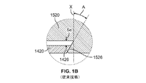
図1Aは、当技術分野で既知の従来のトルクショルダと金属間シールの組合せとを示している。ボックス1520は、ボックスシール面1524と、ボックストルクショルダ1526とを含む。ピン1420は、ピンシール面1424と、ノーズ1428と、ピントルクショルダ1426と、を含む。図1に示すように、ピンシール面1424は、ピン1420の端部に位置される。ピン1420のノーズ1428は、接続が形成されると、ピンシール面1424とピントルクショルダ1426との間に押し込まれる。ピン1420とボックス1520との接続は、パイプとコネクタ(図示せず)との長手方向軸を規定する。軸Xは、長手方向軸に垂直であり、ピンノーズ1428でトルクショルダ1426、1526の端部を通る。ピントルクショルダ1426およびボックストルクショルダ1526はそれぞれ、垂直軸Xに対して角度が付けられた単一のショルダ面を含む。トルクショルダ1426、1526と垂直軸Xとの間に形成される内角Aは、例えば、約−15°、すなわち、軸Xから時計回り方向に15°であってよい。この傾斜角度は従来技術で知られている。この例では、ピンノーズ1428は、ボックスシール面1524とボックストルクショルダ面1526との間にしっかりと押し込まれている。例えば、米国特許第7,334,821号明細書を参照されたい。
FIG. 1A shows a combination of conventional torque shoulderers and metal-to-metal seals known in the art. The
図1Dは、従来技術で既知のプレミアム接続部を示している。図1Bは、トルクショルダ1426、1526がちょうど接触し始めた時点の図1Dの接続部の拡大図を示す。ギャップScは、ピン1420の外面とボックス1520の座ぐり面との間に存在し、組み立てを容易にするために必要である。角度Aは、組み立て後にピン1420とボックス1520とを一緒にロックするのに有益であるが、図1Cは、接続部をさらにねじ込むと、角度Aによってピン1420がボックス1520に衝突することを示している。この望ましくない接触は、組み立て中の接続部の適切な位置決めを妨げる可能性があり、シール面1424、1524またはトルクショルダ1426、1526に損傷を引き起こす可能性がある。
FIG. 1D shows a premium connection known in the prior art. FIG. 1B shows an enlarged view of the connection portion of FIG. 1D at the time when the
本発明によれば、先行技術に勝る利点を含むプレミアム接続部が提供され、例えば、ピンの動きが制御され得、上述のシール面への望ましくない接触および損傷が低減され得る。プレミアム接続部は、複数の表面を有するピンおよびボックストルクショルダを含み、例えば、各トルクショルダは、図2Aから図11Bに示される向きに関して上部および下部トルクショルダ面を有してもよい。本発明による別の特徴は、図2A、図3Aおよび図10Aに示されるように、ショルダ面から離間されたシール面も含む。追加の特徴は、ピンが最終位置に位置させられた後であっても、ピンの端とボックスまたはコネクタの端との間に存在する空間を含む。図5Aおよび図6から図8および図10Aを参照されたい。 INDUSTRIAL APPLICABILITY According to the present invention, a premium connection portion including advantages over the prior art can be provided, for example, pin movement can be controlled, and unwanted contact and damage to the sealing surface described above can be reduced. The premium connection includes pins and box torque shoulderers with multiple surfaces, for example, each torque shoulderer may have upper and lower torque shoulderer surfaces with respect to the orientations shown in FIGS. 2A-11B. Another feature according to the invention also includes a sealing surface separated from the shoulder surface, as shown in FIGS. 2A, 3A and 10A. An additional feature includes the space that exists between the end of the pin and the end of the box or connector, even after the pin is in its final position. See FIGS. 5A and 6 to 8 and 10A.
好ましい実施形態では、ピンおよびボックスの上部および下部の両トルクショルダが同時に互いに接触してもよい。このように、コネクタはピンに対して、中立の捕捉を提供する。別の好ましい実施形態では、ピンおよびボックスの下部トルクショルダ面が互いに接触する前に、ピンおよびボックスの上部トルクショルダ面が互いに接触してもよい。この実施形態では、ピンは下向きに曲がってもよい。図6を参照されたい。さらに好ましい実施形態では、ピンおよびボックスの上部トルクショルダ面が互いに接触する前に、ピンおよびボックスの下部トルクショルダ面が互いに接触してもよい。この実施形態では、ピンは上向きに曲がってもよい。図2Bおよび図3Bを参照されたい。その結果、ピンの動きを所望に応じて制御することができる。 In a preferred embodiment, both the pin and the upper and lower torque shoulders of the box may come into contact with each other at the same time. In this way, the connector provides a neutral capture for the pin. In another preferred embodiment, the upper torque shoulder surfaces of the pins and the box may come into contact with each other before the lower torque shoulder surfaces of the pins and the box come into contact with each other. In this embodiment, the pin may bend downward. See FIG. In a more preferred embodiment, the pin and the lower torque shoulder surface of the box may come into contact with each other before the upper torque shoulder surface of the pin and the box come into contact with each other. In this embodiment, the pins may bend upwards. See FIGS. 2B and 3B. As a result, the movement of the pin can be controlled as desired.
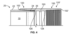
図4は、第1段階の刺し込まれた位置にあるオイルパイプ10およびコネクタ100の断面図を示す。図2Aおよび図2Bは、回転が生じた後の第2段階でのオイルパイプ10とコネクタ100との接続を示す。オイルパイプ10は、ねじ部22と、ピンシール面24と、自由端にあるトルクショルダ26とを有するピン20を有する。ピントルクショルダ26は、第1の表面26aおよび第2の表面26bを含む。コネクタ100は、2つのボックス120、120’を有する。各ボックス120、120’は、半径方向内側の突出部150に、ねじ部122、ボックスシール面124およびトルクショルダ126を有する。ボックストルクショルダ126は、第1の表面126aおよび第2の表面126bを含む。この実施形態では、第1のボックスショルダ面126aは第1のピンショルダ面26aと相補的であり、第2のボックスショルダ面126bは第2のピンショルダ面26bと相補的である。
FIG. 4 shows a cross-sectional view of the
コネクタ100は、図4に示されるように、2つの自由端102および102’を有する。上述のように、刺し込まれた位置では、ピン10のねじ部22がボックス120、120’のねじ部122に接触するまで、オイルパイプ10がコネクタ100に刺し込まれるか配置される。ピン10とボックス120、120’との間には、回転は未だ発生していない。ピン10およびボックス120、120’が回転すると、接続が形成される。
構成のこの第2段階は、ねじ22、122またはシール面24、24が互いにちょうど接触し始めるハンドタイト位置として知られている。ピン20のねじ22は、ボックス120のねじ122に噛み合う。ピンシール面24とボックスシール面124とがちょうど接触し始める。ハンドタイト位置では、ピントルクショルダ26の第1の表面26a、126aとボックストルクショルダ126との間にギャップまたはスタンドオフ「Sa」が存在し、ピントルクショルダ26の第2の表面26bと、ボックストルクショルダ126の126bとの間にギャップまたはスタンドオフ「Sb」が存在する。この実施形態では、スタンドオフSaは、例えば、約0.06インチであり、スタンドオフSbは、例えば、約0.03インチである。スタンドオフSaおよびSbは、設計されたシール干渉およびシール角度の結果として異なってもよく、同じである必要はない。
This second stage of construction is known as the hand tight position where the
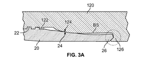
ピン20の端部にはノーズ27が延びる。ノーズ27は、ピン20の内面21と外面23との間に、長手方向軸に垂直な軸である軸Pの方向にトルクショルダ26の長さに沿って位置される。ノーズ27は、トルクショルダ26の第1の表面26aと第2の表面26bとを接続する頂点である。この実施形態では、第1の表面26aは、外面23からノーズ27まで一方向に延び、パイプ10の外周の周りで第2の方向に延びる。第2の表面26bは、内面21からノーズ27まで一方向に延び、パイプ10の内周の周りで第2の方向に延びる。ノーズ27の位置は、図1Aに示されるノーズ1428の位置とは異なる。図1Aでは、ノーズは、ピン1420の外面にあるトルクショルダ1426の一端、およびピンシール面1424またはその付近に位置される。図2Aから図11に示すように、ノーズ27は、ピントルクショルダ26の一端に位置されていない。その代わりに、ノーズ27は、プロファイル図でのショルダ26の長さに関してピントルクショルダ26の中間部または中央部にある。ノーズ27の形状は様々であってよく、例えば、角形、ソケット、平らな端、ブルノーズ、バルブ、円錐状、丸みを帯びた形状、魚尾状などであってよい。凹部127は、長手方向軸に垂直な方向にトルクショルダ126の長さに沿って位置され、第1の表面126aと第2の表面126bとを接続する頂点である。この実施形態では、ノーズ27および凹部127の形状は相補的であるため、ピン10がコネクタ100にねじ込まれるとノーズ27と凹部127とは嵌め合わされ、凹部127はノーズ27に接触し、ピンショルダ26はボックスショルダ126に接触する。(図5)。
A
スタンドオフSaとスタンドオフSbとの幅の差は、ノーズ27が長手方向軸に関して凹部127と最初に位置合わせされていないために生じる。図2Bおよび図3Bに示すように、ノーズ27は凹部127の下に位置される。ノーズ27と凹部127との間のこのオフセットにより、ノーズ27が凹部127に受け入れられると、ピン10が上向きに曲げられる。ピン10が曲がることにより、ノーズ27が凹部127に押し込まれ、接続がさらに緊密になる。別の実施形態では、ノーズ27は凹部127の上方に位置し得るため、ピンが下向きに曲げられ、それによって接続がさらに緊密になる。例えば、図6を参照されたい。
The difference in width between standoff Sa and standoff Sb occurs because the
図3Aおよび図3Bは、構成の第3段階である第1のショルダタイト位置を示し、これは、ボックス120に対してピン20をさらに回転させた後に生じる。トルクショルダ26、126が互いに接触するまでボックス120にピン20をねじ込むことによって、シール面24、124が互いに押し付けられる。この好ましい実施形態では、例えば、相補的な第2の表面26b、126bは互いにちょうど接触する。その結果、第2の表面26b、126間のスタンドオフSbが除去される。しかし、相補的な第1の表面26a、126a間のスタンドオフSaは依然として存在する。ショルダ26、126間の接触点の後、追加の回転は未だ生じていないため、この位置では、ショルダ26、126に対して追加のトルク力は加えられない。半径方向の距離S1が、ピン20の端とボックス120の表面BSとの間に存在する。シール面24、124の相対角度は、接続部に設計されたシール干渉量S1だけピン20の端とボックス120の表面BSとを押し離して、漏出防止シールを形成するために十分な接触圧力をもたらす。
3A and 3B show the first shoulder titite position, which is the third stage of construction, which occurs after the
構成の第4段階である第2のショルダタイト位置は、ボックス120に対してピン20をさらに回転させた後に生じる。トルクショルダの第1の表面26a、126aが互いに接触するまでボックス120にピン20をねじ込むことによって、シール面24、124が互いにさらに押し付けられる。半径方向の距離S1は、頂点27、127間の半径方向のオフセット量だけ縮小される。ピンの端部を半径方向外向きに押すと、シール面24、124が互いにさらに緊密になり、さらに優れたシールがもたらされる。第1のショルダ面と第2のショルダ面との間のV字形により、ギャップS1がゼロになってボックスとピンとの間に望ましくない接触が生じるのを防ぐ。
The second shoulder titite position, which is the fourth stage of the configuration, occurs after further rotation of the
接続部を構成する第5の最終段階は、パワータイト位置である。パワータイト段階の間、トルクショルダ26、126に追加のトルクが加えられるが、追加の回転はほとんど発生しない(例えば、約0.01回転)。追加の回転はほとんど発生しないため、接続部のパワータイト位置は、図3Aおよび図3Bに示すショルダタイト位置のように見える。 The fifth final step of forming the connection is the power tight position. During the power tight phase, additional torque is applied to the torque shoulders 26, 126, but little additional rotation occurs (eg, about 0.01 rotations). Since little additional rotation occurs, the power tight position of the connection looks like the shoulder tight position shown in FIGS. 3A and 3B.
トルクの増加量は、摩擦、ピンの剛性、シール領域周辺のボックスの剛性、ねじの干渉量(該当する場合)、潤滑剤、およびシールの干渉量の関数である。シール面24、124が互いに接触すると、トルクが急速に増加し始める。トルクの増加は、シール面24、124が互いに押し込まれることによって生じる。トルクは、ショルダ26、126がショルダタイト位置で接触するまでほぼ一定の割合で増加し続ける。ショルダ26、126が互いに接触すると、トルクは極めて急速に増加する。ショルダ26、126が接触すると、所定のパワータイト位置に到達し、所望のトルク量が達成されるまで、追加のトルクが加えられる。所望の最終的な構成トルクに到達するために、接続部をさらに回転させる必要はほとんどない(例えば、約0.01回転)。
The amount of torque increase is a function of friction, pin stiffness, box stiffness around the seal area, screw interference (if applicable), lubricant, and seal interference. When the sealing surfaces 24 and 124 come into contact with each other, the torque begins to increase rapidly. The increase in torque is caused by the sealing surfaces 24 and 124 being pushed into each other. The torque continues to increase at a substantially constant rate until the
図5Aおよび図5Bは、本発明によるトルクショルダの実施形態の断面図を示す。図5Aおよび図5Bに示すように、図2Aから図4の実施形態では、ピン20は雄型部品として設計され、ボックス120は雌型部品として設計されているため、ボックス120はピン20を受け入れることができる。この実施形態では、ピントルクショルダ26およびボックストルクショルダ126はともにV字形断面を有する。ピンシール面24およびボックスシール面124は、パイプおよびコネクタの接続部によって規定される長手方向軸(図示せず)に関して、それぞれのトルクショルダ26、126から離間している。トルクショルダは、別の形状または設計の断面を有してもよい。
5A and 5B show cross-sectional views of an embodiment of a torque shoulderer according to the present invention. As shown in FIGS. 5A and 5B, in the embodiments of FIGS. 2A-4, the
ピントルクショルダ26のV字形延長部は、ボックストルクショルダ126のV字形受け部と係合して、ピン20が複数の方向、例えば半径方向内向きまたは外向きに移動するのを低減または防止する。例えば、第1の表面26a、126aは、ピン20のノーズ27を下方に維持することにより、ピン20がボックス120の隅に上向きに打ち込まれるのを防ぐ。また、第2の表面26b、126bは、外部から加えられた圧力がピン20を内向きに押し付けるのを防ぎ、これによりシール面24、124の付勢を弱める。
The V-shaped extension of the
内角Vaは、第1の表面26a、126aと軸Pとの間に形成される。内角Vaは、15°であってよく、これは軸Pに対して反時計回り方向に15°である。内角Vbは、第2の表面26b、126bと軸Pとの間に形成される。内角Vbは、−15°であってよく、これは軸Pに対して時計回り方向に15°である。角度Va、Vbは様々であってよく、例えばそれぞれ3〜60°、−3〜−60°であってよい。さらに、内角Vaは、内角Vbの絶対値と異なっていても、内角Vbの絶対値に等しくてもよい。例えば、図5Bに示すように、角度Vaは15°であり、−45°である角度Vbの絶対値に等しくなく、15°≠|−45°|であるため、Va≠|Vb|である。別の例では、角度Vaは20°であり得、角度Vbは−10°であり得、この場合、20°≠|−10°|であるため、Va≠|Vb|である。
The internal angle Va is formed between the
図5Bに示すように、ノーズ27および凹部127は、軸Pの方向でショルダ26a、26b、126a、126bの長さに対して中心のトルクショルダまたはその付近に位置される。第1のピン面26aは、第2のピン面26bと同一またはほぼ同様の長さを有し、第1のボックス面126aは、第2のボックス面126と同一またはほぼ同様の長さを有する。図5Bの実施形態では、ノーズ27および凹部127は、内角Va、Vbの頂点として機能するが、これは好ましい実施形態の非限定的な例である。ノーズ27、凹部127および角度Va、Vbを含むトルクショルダ26、126の形状は可変である。異なる形状と頂点の位置とが使用されてもよい。表面26a、26b、126a、126bまたはVa、Vbの異なる形状または角度が使用されてもよい。例えば、ノーズ27の位置は、トルクショルダ26の中心にある必要はなく、代わりに、外面23よりも内面21の近くに位置されてもよい。
As shown in FIG. 5B, the
図6の別の好ましい実施形態に示すように、第1の表面26a、126aは第2の表面26b、126bよりも長く、第1の角度Vaは第2の角度Vbの絶対値よりも大きい。図7は、第1の表面26a、126aが第2の表面26b、126bよりも短く、第1の角度Vaが第2の角度Vbよりも小さいことを示している。第1の表面26a、126a、第2の表面26b、126b、および頂点(ノーズ、凹部)27、127の形状は、所望の結果が得られるように設計される。上述のように、頂点27、127は、例えば、ピンの端部を押し下げて、ピンの曲げを真っ直ぐにするか最小限に抑えるために、最初は位置ずれしていてもよい。あるいは、例えば、シール24、124に対する接触圧力を高めるために、ピン20の端部を押し上げる必要がある場合がある。
As shown in another preferred embodiment of FIG. 6, the
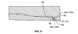
図8は、トルクショルダ26、126の別の好ましい実施形態を示し、ショルダ26、126は、図5から図7に示されるV字形断面とは対照的に、弾丸、ブルノーズまたは湾曲形状の断面を有する。第1の表面26aは第1の半径Raを有し、第2の表面26bは第2の半径Rbを有し、第1の表面126aは第3の半径Rcを有し、第2の表面126bは第4の半径Rdを有する。第1および第3の半径Ra、Rcは、第2および第4の半径、それぞれRb、Rdと異なっていても等しくてもよい。ノーズ27は、第1の表面26aと第2の表面26bとの間に位置される。凹部127は、第1の表面126aと第2の表面126bとの間に位置される。V字形断面の実施形態に関して上述したように、第1の表面26a、126a、第2の表面26b、126bおよび半径Ra、Rb、Rc、Rdおよび頂点は、ピン20を押し上げるか押し下げて、ボックス120に対してピン20を所望の位置に捕捉するように調整されてもよい。別の実施形態では、ピンは単一の半径を有する単一の表面を有してもよく、ボックスは単一の半径を有する単一の表面を有してもよい。この実施形態では、ピン半径とボックス半径とは等しくても等しくなくてもよく、半径の中心線は軸から同じ距離であってもなくてもよい。2つの半径が互いに対して半径方向にオフセットされている場合、ピンの端部は、2つの半径のオフセット方法に応じて、上向きまたは下向きに押し付けられる。
FIG. 8 shows another preferred embodiment of the torque shoulders 26, 126, which have a bullet, bull nose or curved cross section as opposed to the V-shaped cross section shown in FIGS. 5-7. Have. The
トルクショルダ26、126のV字形断面およびブルノーズ断面設計は、雄型および雌型の形状がボックス内の半径方向の位置にピンを捕捉または拘束し、それによってピンの移動を低減または防止するため、従来技術よりも有利である。ショルダ26、126の設計を調整することにより、ピンの曲げ、湾曲またはたわみが補償されるか最小限に抑えられ得る。さらに、シール面24、124の接触圧力が増加し得る。同様に他の利点もそこから得られる可能性がある。
The V-shaped and bullnose cross-section designs of the
好ましくは、第1および第2の角度Va、Vbまたは第1および第2の半径Ra、Rbは、ピン20に作用する力Fの比較的大きい成分が半径方向成分Rではなく軸方向成分Aであるように十分に小さくなるように設計される。図9を参照されたい。
Preferably, in the first and second angles Va, Vb or the first and second radii Ra, Rb, the component having a relatively large force F acting on the
図10Aおよび図10Bは、図2Aから図9に示された実施形態と比較してV字形のショルダの設計が反転されたピンおよびボックスのトルクショルダ接続を示す。この実施形態では、ピン220は雌部材であり、ボックス320は雄部材である。ボックス320は、ボックスシール面324、第1のショルダ面326a、第2のショルダ面326bを含む。ノーズ327は、第1のショルダ面326aと第2のショルダ面326bとの間に形成される。ピン220は、ピンシール面224、第1のショルダ面226aおよび第2のショルダ面226bを含む。凹部227は、第1のショルダ面226bと第2のショルダ面226bとの間に形成される。この実施形態では、ボックス面326aと326bとの間の頂点はノーズ327を形成し、ピン面226aと226bとの間の頂点は凹部227を形成する。ノーズ327と凹部とは相補的な表面であるため、ノーズ327は、図2aから図5Bに関して上述したのと同じようにボックス320内でピン220を回転させることにより凹部227に受け入れられる。この反転されたショルダの設計は、図8に示すブルノーズの実施形態にも適用され得る。
10A and 10B show a pin and box torque shoulderer connection in which the V-shaped shoulder design is reversed as compared to the embodiments shown in FIGS. 2A-9. In this embodiment, the
図11Aおよび図11Bは、本発明のさらに好ましい実施形態による、ピン520およびボックス420が異なるショルダ面形状を有し、頂点527および427が互いに相補的ではないトルクショルダ接続を示す。図11Aは、第1のショルダ面526aおよび第2のショルダ面526bを有する、丸みを帯びたまたはブルノーズのショルダ面526を有するピン520を示す。頂点527は、第1のショルダ面526aと第2のショルダ面526bとの間に位置される。ボックス420は、第1のショルダ面426aおよび第2のショルダ面426bを有するV字形のボックスショルダ面426を含む。頂点427は、第1のショルダ面426aと第2のショルダ面426bとの間に位置される。ピン520およびボックス420は、図2Aから図5Bに関して上述したのと同じように互いに接触する。ボックス420へのピン520の回転により、第1のショルダ面526aと第1のショルダ面426aとの接触、および第2のショルダ面526bと第2のショルダ面426bとの接触がもたらされる。図11Aおよび図11Bに示される実施形態では、ショルダ526およびショルダ426の異なる表面形状のために、頂点427および頂点527が互いに接触できない。構成後、頂点426、526間にギャップまたは空間530が存在する。また、ショルダ面526、426の形状および設計の変動により、ショルダ面526、426は、表面526、426の一部に沿って互いに接触しない。
11A and 11B show a torque shoulder connection in which the
図11Bは、V字形のピンショルダ面526を有するピン520と、丸みを帯びたまたはブルノーズのボックスショルダ面426を有するボックス420とを示す。ピンショルダ面526は、第1のショルダ526aおよび第2のショルダ面526bを有する。頂点527は、第1のショルダ面526aと第2のショルダ面526bとの間に位置される。ボックスショルダ面426は、第1のショルダ面426aおよび第2のショルダ面426bを有する。頂点427は、第1のショルダ面426aと第2のショルダ面426bとの間に位置される。ピン520およびボックス420は、図2Aから図5Bおよび図11Aに関して上述したのと同じように互いに接触する。ボックス420へのピン520の回転により、第1のショルダ面526aと第1のショルダ面426aとの接触、および第2のショルダ面526bと第2のショルダ面426bとの接触がもたらされる。頂点427と527との間に空間530が存在する。
FIG. 11B shows a
図11Aおよび図11Bでは、構成中にピン520がボックス420内に挿入されると同時にピンショルダ面526a、526bがボックスショルダ面426a、426bに接触するように頂点527および427が互いに位置合わせされるように、ピン520およびボックス420が設計されてもよい。その代わりに、第1のショルダ面526a、426aが最初に接触し、次にピン520がボックス520にさらにねじ込まれると第2のショルダ面526b、426bが接触するように、ショルダ面526、426および頂点527、427が設計されてもよい。別の変形例では、第2のショルダ面526b、426bが最初に接触し、次にピン520がボックス520にさらにねじ込まれると第1のショルダ面526a、426aが接触するように、ショルダ面526、426および頂点527、427が設計されてもよい。
In FIGS. 11A and 11B, the
ショルダ面426、526は、例えば、限定されるものではないが、ブルノーズ、弾丸形、角形、丸みを帯びた形状または魚尾状を含む様々な形状で設計されてもよい。 The shoulder surfaces 426 and 526 may be designed in a variety of shapes, including but not limited to, for example, a bull nose, a bullet, a square, a rounded shape or a fish tail.
前述の明細書では、特定の例示的な実施形態およびその例を参照して本発明を説明されている。しかし、以下の特許請求の範囲に記載された本発明のさらに広い主旨および範囲から逸脱することなく、様々な修正および変更を加えることができることは明らかであろう。したがって、本明細書および図面は、限定的な意味ではなく例示的な方法で考慮されるべきである。 In the above specification, the present invention is described with reference to specific exemplary embodiments and examples thereof. However, it will be clear that various modifications and modifications can be made without departing from the broader gist and scope of the invention described in the claims below. Therefore, the specification and drawings should be considered in an exemplary manner rather than in a limited sense.
Claims (12)
雄ねじと、ピンシール面と、自由端にあるピントルクショルダと、を有するピンと、
ピンを受け入れるためのボックスであって、雄ねじと相互作用するための雌ねじと、ピンシール面と接触するためのボックスシール面と、ピントルクショルダと接触するためのボックストルクショルダとを有する、ボックスと、
を含み、
ピンとボックスとが長手方向軸を規定し、
ピントルクショルダが、外側向きの第1のピンショルダ面と内側向きの第2のピンショルダ面とを有し、第1のピンショルダ面が、長手方向軸に垂直な軸と第1の角度で交差し、第2のピンショルダ面が、垂直軸と第2の角度で交差し、第1のピンショルダ面が、第2のピンショルダ面よりも長く、第1の角度の絶対値が、第2の角度の絶対値よりも大きく、
ボックストルクショルダが、内側向きの第1のボックスショルダ面と外側向きの第2のボックスショルダ面とを有し、第1のボックスショルダ面が、長手方向軸に垂直な軸と第3の角度で交差し、第2のボックスショルダ面が、垂直軸と第4の角度で交差し、第1のボックスショルダ面が第2のボックスショルダ面よりも長い、ねじ付き管状接続部。 The threaded tubular connection is a threaded tubular connection.
A pin having a male screw, a pin seal surface, and a pin torque shoulder at the free end,
A box that is a box for receiving pins and has a female screw for interacting with a male screw, a box seal surface for contacting a pin seal surface, and a box torque shoulderer for contact with a pin torque shoulderer.
Including
Pins and boxes define the longitudinal axis,
The pin torque shoulderer has an outward-facing first pin-shoulder surface and an inward-facing second pin-shoulder surface, the first pin-shoulder surface intersecting an axis perpendicular to the longitudinal axis at a first angle. The second pinshoulder plane intersects the vertical axis at a second angle, the first pinshoulder plane is longer than the second pinshoulder plane, and the absolute value of the first angle is the absolute value of the second angle. Greater than
The box torque shoulderer has a first box shoulderer surface facing inward and a second box shoulderer surface facing outward, with the first box shoulderer surface at an axis perpendicular to the longitudinal axis and a third angle. crossed, second box shoulder surface, intersect the vertical axis and the fourth angle, the first box shoulder surface is long than the second box shoulder surface, roots Ji with tubular connection.
雄ねじと、ピンシール面と、自由端にあるピントルクショルダと、を有するピンを提供する工程であって、ピントルクショルダが、第1の方向に延びる外側向きの第1のピンショルダ面と、第2の方向に延びる内側向きの第2のピンショルダ面とを含み、外側向きの第1のピンショルダ面が、内側向きの第2のピンショルダ面よりも長い、工程と、
雌ねじと、ボックスシール面と、自由端にあるボックストルクショルダと、を有するボックスを提供する工程であって、ボックストルクショルダが、第3の方向に延びる内側向きの第1のボックスショルダ面と、第4の方向に延びる外側向きの第2のボックスショルダ面とを含み、内側向きの第1のボックスショルダ面が、外側向きの第2のボックスショルダ面よりも長い、工程と、
ボックスにピンを刺し込んで、雄ねじと雌ねじとを互いに噛み合わせる工程と、
ピンシール面がボックスシール面に接触するまで、ボックスに対してピンを回転させる工程と、
第1のボックスショルダ面が第1のピンショルダ面に接触し、第2のボックスショルダ面が第2のピンショルダ面に接触するまで、ボックスに対してピンをさらに回転させる工程と、
を含む、方法。 A method of forming a threaded tubular connection, the process of
A step of providing a pin having a male screw, a pin seal surface, and a pin torque shoulder at a free end, wherein the pin torque shoulder extends outward in a first direction and a first pin shoulder surface and a second. A process in which the outward-facing first pin-shoulder surface is longer than the inward-facing second pin-shoulder surface, including an inward-facing second pin-shoulder surface extending in the direction of.
A step of providing a box having a female screw, a box seal surface, and a box torque shoulderer at a free end, wherein the box torque shoulderer extends in a third direction with an inward first box shoulderer surface. A process in which the first box shoulder surface facing inward is longer than the second box shoulder surface facing outward, including an outward second box shoulder surface extending in a fourth direction.
The process of inserting a pin into the box and engaging the male and female threads with each other,
The process of rotating the pin with respect to the box until the pin seal surface contacts the box seal surface,
A step of further rotating the pin with respect to the box until the first box shoulder surface contacts the first pin shoulder surface and the second box shoulder surface contacts the second pin shoulder surface.
Including methods.
Priority Applications (2)
| Application Number | Priority Date | Filing Date | Title |
|---|---|---|---|
| JP2021145180A JP2021191975A (en) | 2017-03-03 | 2021-09-07 | Torque shoulder of premium connection part |
| JP2023098286A JP2023116707A (en) | 2017-03-03 | 2023-06-15 | Torque shoulder of premium connection |
Applications Claiming Priority (5)
| Application Number | Priority Date | Filing Date | Title |
|---|---|---|---|
| US15/449,350 US20180252343A1 (en) | 2017-03-03 | 2017-03-03 | Torque shoulder of a premium connection |
| US15/449,350 | 2017-03-03 | ||
| US15/634,558 US10612702B2 (en) | 2017-03-03 | 2017-06-27 | Torque shoulder of a premium connection |
| US15/634,558 | 2017-06-27 | ||
| PCT/IB2018/051287 WO2018158707A1 (en) | 2017-03-03 | 2018-02-28 | Torque shoulder of a premium connection |
Related Child Applications (1)
| Application Number | Title | Priority Date | Filing Date |
|---|---|---|---|
| JP2021145180A Division JP2021191975A (en) | 2017-03-03 | 2021-09-07 | Torque shoulder of premium connection part |
Publications (2)
| Publication Number | Publication Date |
|---|---|
| JP2020509315A JP2020509315A (en) | 2020-03-26 |
| JP6942809B2 true JP6942809B2 (en) | 2021-09-29 |
Family
ID=63355550
Family Applications (3)
| Application Number | Title | Priority Date | Filing Date |
|---|---|---|---|
| JP2019547651A Active JP6942809B2 (en) | 2017-03-03 | 2018-02-28 | Premium connection torque shoulderer |
| JP2021145180A Pending JP2021191975A (en) | 2017-03-03 | 2021-09-07 | Torque shoulder of premium connection part |
| JP2023098286A Pending JP2023116707A (en) | 2017-03-03 | 2023-06-15 | Torque shoulder of premium connection |
Family Applications After (2)
| Application Number | Title | Priority Date | Filing Date |
|---|---|---|---|
| JP2021145180A Pending JP2021191975A (en) | 2017-03-03 | 2021-09-07 | Torque shoulder of premium connection part |
| JP2023098286A Pending JP2023116707A (en) | 2017-03-03 | 2023-06-15 | Torque shoulder of premium connection |
Country Status (13)
| Country | Link |
|---|---|
| US (3) | US20180252343A1 (en) |
| EP (3) | EP4163470A1 (en) |
| JP (3) | JP6942809B2 (en) |
| KR (4) | KR102344269B1 (en) |
| CN (2) | CN113585984A (en) |
| CA (2) | CA3053883C (en) |
| DK (2) | DK3922807T3 (en) |
| HU (2) | HUE061162T2 (en) |
| MX (1) | MX2019010217A (en) |
| RU (2) | RU2753544C2 (en) |
| UA (1) | UA125654C2 (en) |
| WO (1) | WO2018158707A1 (en) |
| ZA (1) | ZA201904997B (en) |
Families Citing this family (5)
| Publication number | Priority date | Publication date | Assignee | Title |
|---|---|---|---|---|
| EP3572701B1 (en) * | 2017-01-18 | 2021-08-18 | Nippon Steel Corporation | Threaded connection for steel pipes |
| US20180252343A1 (en) * | 2017-03-03 | 2018-09-06 | Arcelormittal Tubular Products Luxembourg S.A. | Torque shoulder of a premium connection |
| MX2019012982A (en) * | 2017-05-22 | 2019-12-18 | Nippon Steel Corp | Screw joint for steel pipe. |
| US11859461B2 (en) * | 2022-03-30 | 2024-01-02 | Halliburton Energy Services, Inc. | Metal to metal tubular connection with controlled support structure |
| US11940064B2 (en) | 2022-06-17 | 2024-03-26 | Saudi Arabian Oil Company | Threaded tubular connection |
Family Cites Families (59)
| Publication number | Priority date | Publication date | Assignee | Title |
|---|---|---|---|---|
| BE633562A (en) | 1962-06-26 | |||
| US3359013A (en) * | 1965-09-03 | 1967-12-19 | Hydril Co | Deep well casing jont |
| JPS5211765B2 (en) * | 1972-03-31 | 1977-04-02 | ||
| US4550937A (en) | 1978-02-27 | 1985-11-05 | Vallourec S.A. | Joint for steel tubes |
| US4384737A (en) | 1980-04-25 | 1983-05-24 | Republic Steel Corporation | Threaded joint for well casing and tubing |
| JPS5944552B2 (en) | 1981-05-14 | 1984-10-30 | 新日本製鐵株式会社 | Highly airtight oil country pipe threaded joint |
| US4433862A (en) | 1982-04-13 | 1984-02-28 | Otis Engineering Corporation | Pipe joint |
| JPS58193993A (en) * | 1982-05-08 | 1983-11-11 | 住友金属工業株式会社 | Pipe joint for oil well pipe |
| DE3472131D1 (en) | 1983-04-26 | 1988-07-21 | Hydril Co | Tubular connection with cylindrical and tapered stepped threads |
| US4629224A (en) | 1983-04-26 | 1986-12-16 | Hydril Company | Tubular connection |
| US4537429A (en) | 1983-04-26 | 1985-08-27 | Hydril Company | Tubular connection with cylindrical and tapered stepped threads |
| US4624488A (en) | 1983-12-16 | 1986-11-25 | Hydril Company | Tubular connection |
| GB8414203D0 (en) * | 1984-06-04 | 1984-07-11 | Hunting Oilfield Services Ltd | Pipe connectors |
| JPS616488A (en) | 1984-06-20 | 1986-01-13 | 日本鋼管株式会社 | Screw coupling for oil well pipe |
| US4795200A (en) | 1986-12-04 | 1989-01-03 | Hydril Company | Lengthened tubular pin member nose for improving sealing integrity and bearing forces |
| US5137310A (en) | 1990-11-27 | 1992-08-11 | Vallourec Industries | Assembly arrangement using frustoconical screwthreads for tubes |
| DE4446806C1 (en) | 1994-12-09 | 1996-05-30 | Mannesmann Ag | Gas-tight pipe connection |
| JP3287197B2 (en) * | 1995-11-30 | 2002-05-27 | 住友金属工業株式会社 | Threaded fittings for oil country tubular goods |
| US6047997A (en) | 1996-05-15 | 2000-04-11 | Iberia Threading, Inc. | Threaded connection with radiused surfaces |
| US6485063B1 (en) * | 1996-05-15 | 2002-11-26 | Huey P. Olivier | Connection |
| EP0916883B1 (en) * | 1997-05-30 | 2006-06-28 | Sumitomo Metal Industries, Ltd. | Screw joint for oil well pipe |
| CN2351541Y (en) | 1998-08-27 | 1999-12-01 | 辽河石油勘探局钻井二公司 | Non-hoop double-stage synchronous screwed pipe |
| EP1046779A1 (en) * | 1999-04-19 | 2000-10-25 | Hydril Company | Threaded pipe connection |
| US7690696B2 (en) | 1999-04-19 | 2010-04-06 | Hydril Company | Wedge thread with torque shoulder |
| DE19955377C2 (en) | 1999-11-10 | 2002-05-02 | Mannesmann Ag | pipe connection |
| US6626471B2 (en) * | 2000-08-10 | 2003-09-30 | Hydril Company | Double flex seal for tubular connection |
| FR2833335B1 (en) | 2001-12-07 | 2007-05-18 | Vallourec Mannesmann Oil & Gas | UPPER TUBULAR THREADING CONTAINING AT LEAST ONE THREADED ELEMENT WITH END LIP |
| FR2844331B1 (en) | 2002-01-03 | 2004-11-26 | Vallourec Mannesmann Oil & Gas | PROCESS FOR PRODUCING A SEALED TUBULAR JOINT WITH PLASTIC EXPANSION |
| RU42283U1 (en) | 2003-02-11 | 2004-11-27 | Калашников Владислав Алексеевич | CONIC PIPE THREADED CONNECTION |
| US7077197B2 (en) * | 2003-12-19 | 2006-07-18 | Weatherford/Lamb, Inc. | Expandable tubular connection |
| JP2005240888A (en) | 2004-02-25 | 2005-09-08 | Jfe Steel Kk | Screw joint for oil-well pipe |
| FR2889727B1 (en) | 2005-08-09 | 2007-09-28 | Vallourec Mannesmann Oil Gas F | TUBULAR THREAD SEALED WITH LIQUIDS AND GASES |
| UA91751C2 (en) | 2006-03-31 | 2010-08-25 | Сумитомо Мэтал Индастриз, Лтд. | Pipe threaded joint |
| FR2913746B1 (en) | 2007-03-14 | 2011-06-24 | Vallourec Mannesmann Oil & Gas | SEALED TUBULAR THREAD SEAL FOR INTERNAL AND EXTERNAL PRESSURE SOLUTIONS |
| MX2010003334A (en) | 2007-10-03 | 2010-08-04 | Sumitomo Metal Ind | Screw-threaded joint for steel pipe. |
| CN201121782Y (en) | 2007-10-30 | 2008-09-24 | 达力普集团有限公司 | Threaded sleeve with high leak tightness |
| WO2009060552A1 (en) | 2007-11-08 | 2009-05-14 | Sumitomo Metal Industries, Ltd. | Threaded joint for steel pipes |
| FR2925946B1 (en) | 2007-12-28 | 2009-12-11 | Vallourec Mannesmann Oil & Gas | TUBULAR THREADED SEAL AND RESISTANT TO SUCCESSIVE PRESSURE SOLICITATIONS |
| CN201310305Y (en) * | 2008-11-04 | 2009-09-16 | 西安华衡石油管业有限公司 | Screw thread connecting structure of oil pipe for oil well or sleeve of gas well |
| CN201318513Y (en) * | 2008-11-22 | 2009-09-30 | 衡阳华菱连轧管有限公司 | Oil pipe high-pressure gas seal connection structure |
| FR2939490B1 (en) | 2008-12-10 | 2013-01-18 | Vallourec Mannesmann Oil & Gas | SEALED TUBULAR JOINT USED IN THE OIL INDUSTRY AND METHOD OF MAKING SAME |
| FR2940677B1 (en) | 2008-12-29 | 2016-07-22 | Vallourec Mannesmann Oil & Gas France | SEALED TUBULAR JOINT USED IN THE PETROLEUM INDUSTRY |
| FR2952993B1 (en) | 2009-11-20 | 2011-12-16 | Vallourec Mannesmann Oil & Gas | THREADED JOINT |
| GB201005247D0 (en) | 2010-03-29 | 2010-05-12 | Hsc Fzco | An improved seal between pipes |
| CN101975035B (en) * | 2010-10-18 | 2013-07-31 | 西安交通大学 | Airtight seal connecting structure of special threaded buckle for oil sleeve pipe |
| JP5891700B2 (en) * | 2011-10-17 | 2016-03-23 | Jfeスチール株式会社 | Pipe threaded joints |
| CN102678065B (en) * | 2012-06-06 | 2015-09-23 | 无锡西姆莱斯石油专用管制造有限公司 | The special buttress thread union of high sealability |
| CN202755913U (en) * | 2012-07-04 | 2013-02-27 | 中国石油天然气集团公司 | Oil casing joint |
| RU124352U1 (en) * | 2012-07-31 | 2013-01-20 | Открытое акционерное общество "Первоуральский новотрубный завод" | HIGH SEALED THREADED PIPE CONNECTION |
| US9869139B2 (en) | 2012-11-28 | 2018-01-16 | Ultra Premium Oilfield Services, Ltd. | Tubular connection with helically extending torque shoulder |
| US9388925B2 (en) | 2013-02-05 | 2016-07-12 | Ultra Premium Oilfield Services, Ltd | Tubular connection center shoulder seal |
| CN103321585B (en) * | 2013-07-16 | 2015-04-15 | 无锡西姆莱斯石油专用管制造有限公司 | S-shaped shoulder variable tooth width wedge-shaped coupling structure and oil well pipe structure |
| CN204082029U (en) * | 2014-06-30 | 2015-01-07 | 攀成伊红石油钢管有限责任公司 | A kind of oil bushing threaded connector of high torque resistant high leakproofness |
| US10006569B2 (en) * | 2015-02-19 | 2018-06-26 | Arcelormittal Tubular Products Luxembourg S.A. | Threaded connection for pipes, such as oil and gas pipes |
| RU158152U1 (en) | 2015-08-14 | 2015-12-20 | Акционерное общество "Выксунский металлургический завод" | HIGH SEALED COUPLING THREADED CONNECTION OF OIL PIPES |
| RU160886U1 (en) * | 2015-08-21 | 2016-04-10 | Акционерное общество "Выксунский металлургический завод" | HIGH-SEALED THREADED JOINT OF ELECTRIC WELDED CASING OIL PIPES |
| CN106089119B (en) * | 2016-06-03 | 2019-01-18 | 西南石油大学 | A kind of high-performance oil casing pipe special thread jointing |
| US10465458B2 (en) * | 2017-02-03 | 2019-11-05 | Weatherford Technology Holdings, Llc | Apparatus and method of connecting tubulars |
| US20180252343A1 (en) * | 2017-03-03 | 2018-09-06 | Arcelormittal Tubular Products Luxembourg S.A. | Torque shoulder of a premium connection |
-
2017
- 2017-03-03 US US15/449,350 patent/US20180252343A1/en not_active Abandoned
- 2017-06-27 US US15/634,558 patent/US10612702B2/en active Active
-
2018
- 2018-02-28 DK DK21189945.5T patent/DK3922807T3/en active
- 2018-02-28 DK DK18711171.1T patent/DK3589818T3/en active
- 2018-02-28 JP JP2019547651A patent/JP6942809B2/en active Active
- 2018-02-28 RU RU2020124403A patent/RU2753544C2/en active
- 2018-02-28 RU RU2019127646A patent/RU2728642C1/en active
- 2018-02-28 CA CA3053883A patent/CA3053883C/en active Active
- 2018-02-28 CA CA3125149A patent/CA3125149A1/en active Pending
- 2018-02-28 HU HUE21189945A patent/HUE061162T2/en unknown
- 2018-02-28 CN CN202110949162.XA patent/CN113585984A/en active Pending
- 2018-02-28 UA UAA201909573A patent/UA125654C2/en unknown
- 2018-02-28 CN CN201880015152.5A patent/CN110366628B/en active Active
- 2018-02-28 KR KR1020197025633A patent/KR102344269B1/en active IP Right Grant
- 2018-02-28 EP EP22210579.3A patent/EP4163470A1/en active Pending
- 2018-02-28 EP EP18711171.1A patent/EP3589818B1/en active Active
- 2018-02-28 KR KR1020237032758A patent/KR20230142646A/en not_active Application Discontinuation
- 2018-02-28 WO PCT/IB2018/051287 patent/WO2018158707A1/en active Application Filing
- 2018-02-28 KR KR1020227011177A patent/KR102490988B1/en active IP Right Grant
- 2018-02-28 HU HUE18711171A patent/HUE056089T2/en unknown
- 2018-02-28 MX MX2019010217A patent/MX2019010217A/en unknown
- 2018-02-28 EP EP21189945.5A patent/EP3922807B1/en active Active
- 2018-02-28 KR KR1020217042218A patent/KR102585421B1/en active IP Right Grant
-
2019
- 2019-07-30 ZA ZA2019/04997A patent/ZA201904997B/en unknown
-
2020
- 2020-07-17 US US16/931,465 patent/US20200370682A1/en active Pending
-
2021
- 2021-09-07 JP JP2021145180A patent/JP2021191975A/en active Pending
-
2023
- 2023-06-15 JP JP2023098286A patent/JP2023116707A/en active Pending
Also Published As
Similar Documents
| Publication | Publication Date | Title |
|---|---|---|
| JP6942809B2 (en) | Premium connection torque shoulderer | |
| US11614184B2 (en) | Method for making a threaded connection for pipes, such as oil and gas pipes | |
| US20120032435A1 (en) | Threaded joint for tubes, pipes and the like | |
| JP5509219B2 (en) | Sealed tubular connections used in the oil industry | |
| US8246086B2 (en) | Low cost, high performance pipe connection | |
| RU2762926C1 (en) | Threaded connection for steel pipes | |
| WO2024004694A1 (en) | Steel pipe and joint connection mechanism | |
| BR112019017722B1 (en) | TUBULAR THREAD CONNECTION AND METHOD FOR FORMING A TUBULAR THREAD CONNECTION |
Legal Events
| Date | Code | Title | Description |
|---|---|---|---|
| A621 | Written request for application examination |
Free format text: JAPANESE INTERMEDIATE CODE: A621 Effective date: 20191008 |
|
| A977 | Report on retrieval |
Free format text: JAPANESE INTERMEDIATE CODE: A971007 Effective date: 20200807 |
|
| A131 | Notification of reasons for refusal |
Free format text: JAPANESE INTERMEDIATE CODE: A131 Effective date: 20200818 |
|
| A521 | Request for written amendment filed |
Free format text: JAPANESE INTERMEDIATE CODE: A523 Effective date: 20201112 |
|
| A131 | Notification of reasons for refusal |
Free format text: JAPANESE INTERMEDIATE CODE: A131 Effective date: 20210302 |
|
| A521 | Request for written amendment filed |
Free format text: JAPANESE INTERMEDIATE CODE: A523 Effective date: 20210531 |
|
| TRDD | Decision of grant or rejection written | ||
| A01 | Written decision to grant a patent or to grant a registration (utility model) |
Free format text: JAPANESE INTERMEDIATE CODE: A01 Effective date: 20210810 |
|
| A61 | First payment of annual fees (during grant procedure) |
Free format text: JAPANESE INTERMEDIATE CODE: A61 Effective date: 20210908 |
|
| R150 | Certificate of patent or registration of utility model |
Ref document number: 6942809 Country of ref document: JP Free format text: JAPANESE INTERMEDIATE CODE: R150 |