JP6942517B2 - Imaging device and its manufacturing method - Google Patents
Imaging device and its manufacturing method Download PDFInfo
- Publication number
- JP6942517B2 JP6942517B2 JP2017088949A JP2017088949A JP6942517B2 JP 6942517 B2 JP6942517 B2 JP 6942517B2 JP 2017088949 A JP2017088949 A JP 2017088949A JP 2017088949 A JP2017088949 A JP 2017088949A JP 6942517 B2 JP6942517 B2 JP 6942517B2
- Authority
- JP
- Japan
- Prior art keywords
- substrate
- angular velocity
- holding portion
- positioning
- image pickup
- Prior art date
- Legal status (The legal status is an assumption and is not a legal conclusion. Google has not performed a legal analysis and makes no representation as to the accuracy of the status listed.)
- Active
Links
Images


Classifications
-
- H—ELECTRICITY
- H04—ELECTRIC COMMUNICATION TECHNIQUE
- H04N—PICTORIAL COMMUNICATION, e.g. TELEVISION
- H04N23/00—Cameras or camera modules comprising electronic image sensors; Control thereof
- H04N23/60—Control of cameras or camera modules
- H04N23/68—Control of cameras or camera modules for stable pick-up of the scene, e.g. compensating for camera body vibrations
- H04N23/681—Motion detection
- H04N23/6812—Motion detection based on additional sensors, e.g. acceleration sensors
-
- H—ELECTRICITY
- H04—ELECTRIC COMMUNICATION TECHNIQUE
- H04N—PICTORIAL COMMUNICATION, e.g. TELEVISION
- H04N23/00—Cameras or camera modules comprising electronic image sensors; Control thereof
- H04N23/60—Control of cameras or camera modules
- H04N23/68—Control of cameras or camera modules for stable pick-up of the scene, e.g. compensating for camera body vibrations
- H04N23/682—Vibration or motion blur correction
- H04N23/683—Vibration or motion blur correction performed by a processor, e.g. controlling the readout of an image memory
-
- H—ELECTRICITY
- H04—ELECTRIC COMMUNICATION TECHNIQUE
- H04N—PICTORIAL COMMUNICATION, e.g. TELEVISION
- H04N23/00—Cameras or camera modules comprising electronic image sensors; Control thereof
- H04N23/60—Control of cameras or camera modules
- H04N23/68—Control of cameras or camera modules for stable pick-up of the scene, e.g. compensating for camera body vibrations
- H04N23/682—Vibration or motion blur correction
- H04N23/685—Vibration or motion blur correction performed by mechanical compensation
Landscapes
- Engineering & Computer Science (AREA)
- Multimedia (AREA)
- Signal Processing (AREA)
- Adjustment Of Camera Lenses (AREA)
- Studio Devices (AREA)
- Structure And Mechanism Of Cameras (AREA)
Description
本発明は、撮像装置およびその製造方法に関する。 The present invention relates to an image pickup apparatus and a method for manufacturing the same.
従来、カメラや撮影レンズユニットに角速度センサを配置し、手ぶれ等によるカメラ本体や撮影レンズのぶれを検出する方法が知られている。角速度センサは、例えば、ジャイロセンサなどであって、カメラの移動量を表す角速度を周期的に検出し、電気信号に変換して、カメラマイコンに伝達する。特許文献1では、撮影レンズユニットの光軸に対して、略平行な平面に配置された角速度センサにより、撮影レンズユニットのぶれを検出し、被写体の像ぶれを補正する撮影レンズが開示されている。
Conventionally, there has been known a method of arranging an angular velocity sensor in a camera or a shooting lens unit to detect blurring of the camera body or the shooting lens due to camera shake or the like. The angular velocity sensor is, for example, a gyro sensor or the like, which periodically detects the angular velocity representing the amount of movement of the camera, converts it into an electric signal, and transmits it to the camera microcomputer.
また、撮影方法の一つとして流し撮り撮影が知られている。これは、移動している被写体のスピード感を表現する撮影技術であり、撮影者が被写体の動きに合わせてカメラをパンニングすることにより、移動している被写体を静止させて背景は流すことを目的とする。流し撮り撮影では、撮影者が被写体の動きに合わせてパンニングをする必要があるが、被写体の移動速度とパンニング速度との間に差が生じると、被写体がぶれた画像になる。このような問題に対し、流し撮り撮影の補助を行う技術として、手ぶれを補正するためのシフトレンズを移動させることにより、被写体の移動速度とパンニング速度との差を吸収する方法が提案されている。特許文献2では、角速度センサを用いて検出された装置本体の動き、および画像の動きベクトルから検出された補正量に基づいて、光軸シフトレンズの移動で被写体を画像中央に位置させるための補正を行う撮像装置が開示されている。
In addition, panning photography is known as one of the photography methods. This is a shooting technology that expresses the sense of speed of a moving subject, and aims to make the moving subject still and the background flow by panning the camera according to the movement of the subject. And. In panning photography, the photographer needs to pan according to the movement of the subject, but if there is a difference between the moving speed of the subject and the panning speed, the subject becomes a blurred image. To solve this problem, a method has been proposed as a technique for assisting panning photography by moving a shift lens for correcting camera shake to absorb the difference between the moving speed of the subject and the panning speed. .. In
角速度センサは、温度変化によって出力の変化が生じる素子であり、カメラマイコン近傍やグリップ部のように、素子の発熱や撮影者の体温によって、温度変化が生じやすい箇所に近接して配置されると、正常にぶれを検出できないおそれがある。しかしながら、特許文献1や特許文献2では、角速度センサと装置内部の温度変化が生じやすい箇所との位置関係については言及されていない。
The angular velocity sensor is an element whose output changes due to temperature changes, and when it is placed close to a place where temperature changes are likely to occur due to the heat generation of the element or the body temperature of the photographer, such as near the camera microcomputer or the grip part. , There is a risk that blurring cannot be detected normally. However,
また、特許文献1および特許文献2では、角速度センサは、装置内部に配置されたユニット(例えば、シャッタユニットを駆動するためのモータやレンズ駆動用の電源など)の振動の影響を受け、正常にぶれを検出できないおそれがある。
Further, in
このような課題に鑑みて、本発明は、温度変化および振動の影響を受けにくく、高精度にぶれを検出可能な撮像装置およびその製造方法を提供することを目的とする。 In view of such problems, it is an object of the present invention to provide an image pickup apparatus which is not easily affected by temperature changes and vibrations and can detect blurring with high accuracy, and a method for manufacturing the image pickup apparatus.
本発明の一側面としての撮像装置の製造方法は、ぶれを検出可能な撮像装置であって、撮像光学系の光軸方向において被写体側に突出した形状を有するグリップ部と、前記被写体側とは反対側の背面側に配置された背面外装部材と、前記背面外装部材よりも背面側に配置された画像を表示可能な表示部と、前記表示部を前記撮像装置に対して回動可能に支持するヒンジ機構と、前記背面外装部材よりも前記被写体側に配置された前記撮像装置の制御を行う制御素子を備える第1の基板と、前記撮像装置のぶれの角速度を検出する角速度検出部と、前記第1の基板よりも前記被写体側に配置された前記角速度検出部を備える第2の基板と、前記角速度検出部を、光軸方向視において前記撮像光学系の光軸に対して前記グリップ部とは反対側、かつ前記光軸方向において前記第1の基板と前記背面外装部材との間に形成された空間に対して前記被写体側に配置されるように、保持する保持部と、を有する。前記第2の基板は、振動を緩和可能な緩衝部材を備え、前記緩衝部材を介して前記保持部に保持され、前記第2の基板の緩衝部材側の面に角速度検出部の実装領域を覆うように金属材料からなる補強部材が形成され、前記緩衝部材は、前記保持部の前記補強部材側の面に前記角速度検出部の実装領域を覆うように形成され、前記第1の基板側から順に、前記緩衝部材、前記補強部材、前記第2の基板が3層構造で積層され、前記3層構造で積層されている領域に、前記第2の基板を前記保持部に位置決めする第1の位置決め部を備え、前記3層構造で積層されていない領域に、前記第2の基板を前記保持部に位置決めする第2の位置決め部を備えている撮像装置の製造方法であって、前記第1の位置決め部を前記保持部に設けられた治具に突き当てて組み付けることで、前記第2の基板を前記保持部に対して位置決めする第1工程と、その後、前記治具を前記保持部から取り外す第2工程と、を有し、前記第2工程の後、前記第2の位置決め部により前記第2の基板と前記保持部を圧入嵌合することで、前記第2の基板を前記保持部に位置決めする。
また、本発明の他の一側面としての撮像装置は、ぶれを検出可能な撮像装置であって、撮像光学系の光軸方向において被写体側に突出した形状を有するグリップ部と、前記被写体側とは反対側の背面側に配置された背面外装部材と、前記背面外装部材よりも背面側に配置され、画像を表示可能な表示部と、前記表示部を前記撮像装置に対して回動可能に支持するヒンジ機構と、前記背面外装部材よりも前記被写体側に配置され、前記撮像装置の制御を行う制御素子を備える第1の基板と、前記撮像装置のぶれの角速度を検出する角速度検出部と、前記第1の基板よりも前記被写体側に配置され、前記角速度検出部を備える第2の基板と、前記角速度検出部を、光軸方向視において前記撮像光学系の光軸に対して前記グリップ部とは反対側、かつ前記光軸方向において前記第1の基板と前記背面外装部材との間に形成された空間に対して前記被写体側に配置されるように、保持する保持部と、を有し、前記角速度検出部は、前記第2の基板の被写体側の面に取り付けられ、前記第2の基板は、振動を緩和可能な緩衝部材を備え、前記緩衝部材を介して前記保持部に保持され、前記第2の基板の緩衝部材側の面に前記角速度検出部の実装領域を覆うように金属材料からなる補強部材が形成され、前記緩衝部材は、前記保持部の前記補強部材側の面に前記角速度検出部の実装領域を覆うように形成され、前記第1の基板側から順に、前記緩衝部材、前記補強部材、前記第2の基板が3層構造で積層され、前記3層構造で積層されている領域に、前記第2の基板を前記保持部に位置決めする第1の位置決め部を備え、前記3層構造で積層されていない領域に、前記第2の基板を前記保持部に位置決めする第2の位置決め部を備えていることを特徴とする撮像装置。
A method of manufacturing an image pickup device as one aspect of the present invention is an image pickup device capable of detecting blurring, wherein a grip portion having a shape protruding toward the subject side in the optical axis direction of the image pickup optical system and the subject side are A back exterior member arranged on the back side on the opposite side, a display unit capable of displaying an image arranged on the back side of the back exterior member, and the display unit rotatably supported with respect to the image pickup device. A first substrate including a hinge mechanism for controlling the image pickup device arranged on the subject side of the back surface exterior member, an angular velocity detection unit for detecting the angular velocity of the shake of the image pickup device, and the like. The second substrate having the angular velocity detection unit arranged on the subject side of the first substrate and the angular velocity detection unit are gripped with respect to the optical axis of the imaging optical system in the optical axis direction. It has a holding portion that holds the first substrate and the back exterior member so as to be arranged on the subject side with respect to the space formed between the first substrate and the back exterior member in the direction opposite to the optical axis. .. The second substrate includes a cushioning member capable of alleviating vibration, is held by the holding portion via the cushioning member, and covers a mounting area of the angular velocity detection portion on a surface of the second substrate on the cushioning member side. As described above, the reinforcing member made of a metal material is formed, and the cushioning member is formed on the surface of the holding portion on the reinforcing member side so as to cover the mounting area of the angular velocity detecting portion, and is formed in order from the first substrate side. The first positioning for positioning the second substrate on the holding portion in the region where the cushioning member, the reinforcing member, and the second substrate are laminated in a three-layer structure and laminated in the three-layer structure. The first method of manufacturing an image pickup apparatus, which comprises a second positioning portion for positioning the second substrate on the holding portion in a region not laminated in the three-layer structure. A first step of positioning the second substrate with respect to the holding portion by abutting the positioning portion against a jig provided on the holding portion and assembling the positioning portion, and then removing the jig from the holding portion. The second substrate is fitted into the holding portion by press-fitting the second substrate and the holding portion with the second positioning portion after the second step. Position.
Further, the image pickup device as another aspect of the present invention is an image pickup device capable of detecting blurring, and has a grip portion having a shape protruding toward the subject side in the optical axis direction of the image pickup optical system, and the subject side. Is a back exterior member arranged on the opposite back side, a display unit arranged on the back side of the back exterior member and capable of displaying an image, and the display unit rotatable with respect to the image pickup device. A first substrate having a supporting hinge mechanism, a control element arranged on the subject side of the back exterior member and controlling the image pickup device, and an angular velocity detection unit for detecting the angular velocity of the shake of the image pickup device. The second substrate, which is arranged closer to the subject than the first substrate and includes the angular velocity detection unit, and the angular velocity detection unit are gripped with respect to the optical axis of the imaging optical system in the optical axis direction. A holding portion that holds the portion on the side opposite to the portion and on the subject side with respect to the space formed between the first substrate and the back exterior member in the optical axis direction. The angular velocity detection unit is attached to the surface of the second substrate on the subject side, and the second substrate includes a cushioning member capable of alleviating vibration, and is attached to the holding portion via the cushioning member. A reinforcing member made of a metal material is formed on the surface of the second substrate on the cushioning member side so as to cover the mounting area of the angular velocity detection portion, and the cushioning member is on the reinforcing member side of the holding portion. The surface is formed so as to cover the mounting area of the angular velocity detection unit, and the cushioning member, the reinforcing member, and the second substrate are laminated in a three-layer structure in order from the first substrate side, and the three-layer structure is formed. A first positioning portion for positioning the second substrate on the holding portion is provided in the region laminated with the above three-layer structure, and the second substrate is placed on the holding portion in the region not laminated in the three-layer structure. An imaging device including a second positioning unit for positioning.
本発明によれば、温度変化および振動の影響を受けにくく、高精度にぶれを検出可能な撮像装置およびその製造方法を提供することができる。 According to the present invention, it is possible to provide an image pickup apparatus which is not easily affected by temperature changes and vibrations and can detect blurring with high accuracy, and a method for manufacturing the image pickup apparatus.
以下、本発明の好適な実施形態について添付図面を参照して詳細に説明する。なお、以下の実施形態は特許請求の範囲に係る本発明を限定するものでなく、また本実施形態で説明されている特徴の組み合わせの全てが本発明の課題の解決に必須のものとは限らない。 Hereinafter, preferred embodiments of the present invention will be described in detail with reference to the accompanying drawings. It should be noted that the following embodiments do not limit the present invention according to the claims, and not all combinations of features described in the present embodiments are essential for solving the problems of the present invention. No.
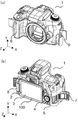
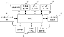
まず、図1および図2を参照して、本発明の実施形態に係る撮像装置の一例であるカメラ本体1の構成について説明する。図1は、カメラ本体1の外観斜視図である。図1(a)は正面側(被写体側)から見たカメラ本体1、図1(b)は背面側(撮影者側)から見たカメラ本体1を示している。図2は、カメラ本体1の主要な構成を示すブロック図である。
First, the configuration of the
カメラ本体1は、撮像光学系によって結像された被写体像を撮像する撮像素子11を有するデジタルカメラである。カメラ本体1の背面には、バリアングルユニット100が設けられている。バリアングルユニット100は、撮像素子11によって取得される画像や、各種設定画面等を表示可能な表示部2を有する。本実施形態では、表示部2として、液晶表示装置が使用されている。表示部2には、タッチパネル3が設けられており、撮影者のタッチ入力操作によって、表示部2の表示切り換え、レリーズ、およびカメラ本体1の各種設定変更などを行うことができる。入力操作部4は、撮影者により操作される操作部材であり、撮影者の操作によって、カメラ本体1の各種設定変更や電源のON/OFFなどを行うことができる。背面外装カバー(背面外装部材)5は、カメラ本体1の外装部品であり、バリアングルユニット100が収納される凹形状が設けられている。
The
グリップ部6は、撮影者がカメラ本体1を保持するためにカメラ本体1の側面に設けられており、撮影者が握りやすいように凸形状を有する。本実施形態では、グリップ部6は、背面側から見たカメラ本体1の右側に設けられている。以下の説明では、背面側(撮影者側)から見たカメラ本体1の右側、すなわちグリップ部6が設けられている側をグリップ側、背面側(撮影者側)から見たカメラ本体1の左側、すなわちグリップ部6が設けられている側とは反対側を反グリップ側という。グリップ部6は、撮影者が握る箇所であるため、撮影者の体温によって温度変化が生じやすい。すなわち、グリップ部6は、温度変化が生じやすい箇所である。メディアドア7は、CFカードやSDカード等の画像等を保存可能な外部メモリに接続可能なコネクタである外部メモリ接続部12に、外部メモリを挿抜するために、開閉可能にグリップ部6に設けられている。インターフェース部9は、USBケーブルや外部機器と接続される。本実施形態では、撮影者がカメラ本体1を握った状態で外部機器の接続を可能にするために、インターフェース部9は反グリップ側に設けられている。
The
マイクロコンピュータ(制御素子。以下、MPU10という)10は、撮像素子11で取得された画像信号を処理し、処理後の画像信号を表示部2に表示する。また、MPU10は、タッチパネル3、入力操作部4またはインターフェース部9に接続された外部機器から受信した入力信号に基づいてカメラ動作の制御や外部機器の制御を行う。例えば、MPU10は、レリーズ操作を検出した場合、ミラーユニット14を所定の位置に退避させた後、シャッタユニット13のシャッタ羽根(不図示)を駆動させることで、撮像素子11に撮影光束を露光させ画像信号を取得する。また、MPU10は、外部メモリ接続部12に接続されている外部メモリに画像データを記録させる。
The microcomputer (control element; hereinafter referred to as MPU 10) 10 processes the image signal acquired by the
角速度センサ(角速度検出部)15は、カメラ本体1の一定時間当たりの角度変化(ぶれ)を検出可能である。MPU10は、角速度センサ15から出力された信号値に基づいて、流し撮り撮影におけるシャッタースピード等の撮影条件の制御を行う。
The angular velocity sensor (angular velocity detection unit) 15 can detect an angular change (blur) of the
バリアングルユニット100は、ヒンジ機構8によってカメラ本体1に対して回動可能に支持されている。撮影者がカメラ本体1を握った状態でバリアングルユニット100の回動を可能にするために、ヒンジ機構8は反グリップ側に設けられている。
The vari-
次に、図3を参照して、バリアングルユニット100の回動動作について説明する。図3は、バリアングルユニット100の回動の説明図である。
Next, the rotation operation of the vari-
ヒンジ機構8は、2軸ヒンジ機構であって、第1の回転軸Aと第2の回転軸Bを有する。バリアングルユニット100は、第1の回転軸Aを中心に、カメラ本体1に対して開閉動作を行うことができる。開閉動作とは、バリアングルユニット100が、第1の回転軸A回りに、図3(a)の表示部2が撮影者側を向いている状態と、図3(b)の表示部2がカメラ本体1側を向き、背面外装カバー5に収納されている状態との間を回動することをいう。
The
また、バリアングルユニット100は、第2の回動軸Bを中心に、回転動作を行うことができる。回転動作とは、バリアングルユニット100が、第2の回転軸B回りに、図3(a)に示される、表示部2が撮影者側を向いている状態と、図3(c)に示される、表示部2がカメラ本体1側を向いている状態との間を回動することをいう。
Further, the vari-
次に、カメラ本体1の内部構成(外装部材を外した状態の構成)について説明する。図4は、カメラ本体1の内部構成の斜視図である。図4(a)は正面側から見たカメラ本体1、図4(b)は背面側から見たカメラ本体1を示している。図5は、カメラ本体1の内部構成の分解斜視図である。
Next, the internal configuration of the camera body 1 (configuration with the exterior member removed) will be described. FIG. 4 is a perspective view of the internal configuration of the
メインベース(第2の保持部)20は、カメラ本体1の骨格であり、樹脂などによって形成されている。撮影者は、ペンタプリズム(ファインダ光学系)21を介してミラーユニット14により反射された被写体像を観察可能である。
The main base (second holding portion) 20 is the skeleton of the
マウント22は、撮影レンズ(撮像光学系)を取り付けるための金属環であり、ステンレスなどの金属材料によって形成されている。撮影レンズは、レンズ着脱ボタン(不図示)の操作により、マウント22に着脱可能に取り付けられる。撮影レンズとカメラ本体1との通信、および撮影レンズを駆動するための電源の供給は、複数の通信ピン23を介して行われる。
The
制御基板(第1の基板)24は、メインベース20に固定され、撮像フレキシブル基板26を介して、撮像基板25と電気的に接続されている。制御基板24および撮像基板25は、プリント配線板(PWB:Printed Wired Board)である。制御基板24は、撮影レンズの光軸方向において、メインベース20に対して背面側(撮影者側)に配置されている。
The control board (first board) 24 is fixed to the
制御基板24は、略コの字形状であり、MPU10をはじめとする多くの電気回路が実装されている。MPU10は、カメラ動作の制御を行うため、多くの信号が集結する。そのため、MPU10は、基板面積の広い箇所に配置することが望ましく、本実施形態では、グリップ部6が設けられていることで基板面積を確保しやすいグリップ側に配置される。MPU10は、データ処理時に発熱するが、特に、動画撮影時やライブビュー撮影時など、膨大なデータ処理を行う場合、高温になる。MPU10の発熱により、制御基板24全体も高温となる。すなわち、制御基板24全体は、温度変化が生じやすい箇所である。また、制御基板24と背面外装カバー5との間の空間は、MPU10の発熱、およびバリアングルユニット100の開閉動作による背面外装カバー5の外気と接する面積の変化(外気への放熱量の変化)により、温度変化が生じやすい箇所である。
The
また、MPU10は、外部メモリ接続部12に接続されている外部メモリとの間で画像信号の伝送を行うため、画像信号へのノイズ影響を考慮すると、外部メモリ接続部12の近傍(グリップ側)に配置されることが望ましい。
Further, since the
撮像基板25には、撮像素子11が実装されている。撮像素子11は、動作時に発熱するが、特に、動画撮影時やライブビュー撮影時など、膨大なデータ処理を行う場合に高温になる。そのため、撮像素子11の発熱により、撮像素子11の近傍も高温になる。すなわち、撮像素子11も含めた撮像素子11の近傍は、温度変化が生じやすい箇所である。
An
電源基板27は、電池16から電力供給を受け、電気回路を駆動するために基板やユニットに供給する電源を生成する。電池16は、カメラ本体1の省スペース化のために、グリップ部6に設けられた凸形状の内部に配置されている。したがって、電源基板27と電池16は、グリップ側に配置されている。
The
フロントユニット(第1の保持部)30は、樹脂などの材料によって形成され、カメラ本体1の内部で駆動可能な駆動部材が取り付けられている。本実施形態では、駆動部材として、撮像素子11の露光時間を調整可能なシャッタユニット13やミラーユニット14の一部であるミラー駆動ユニット14aが取り付けられている。フロントユニット30は、メインベース20に対してビス(不図示)により締結固定されている。フロントユニット30には、プレート32が取り付けられている。プレート32は、ステンレスなどの金属材料によって形成され、撮像基板25を保持する。
The front unit (first holding portion) 30 is made of a material such as resin, and a drive member that can be driven inside the
角速度フレキシブル基板(第2の基板)40は、角速度センサ15が実装されており、メインベース20に固定されている。
The angular velocity flexible substrate (second substrate) 40 is mounted with the
以下、図6および図7を参照して、角速度フレキシブル基板40の構成について説明する。図6は、角速度フレキシブル基板40の説明図である。図6(a)は正面側(被写体側)から見た角速度フレキシブル基板40を示しており、図6(b)は角速度フレキシブル基板40の分解斜視図である。図7は、メインベース20に取り付けられた角速度フレキシブル基板40を示す図である。
Hereinafter, the configuration of the angular velocity
角速度フレキシブル基板40には、上述したように、外装が樹脂材料によって形成された角速度センサ15が半田により実装されており、互いに電気的に接続されている。端子部40bは、制御基板24に実装された角速度接続部に接続されている。これにより、角速度センサ15からの出力信号は、制御基板24上のMPU10に伝送される。
As described above, the
角速度センサ15は、外力、角速度フレキシブル基板40の変形、または高温および低温環境下における角速度フレキシブル基板40の伸縮による影響により、誤検出を起こしやすい。そこで、本実施例では、角速度フレキシブル基板40の裏面に、角速度センサ15の実装領域を覆うように、金属材料によって形成された補強部材41が設けられている。補強部材41を設けることで、外力や、角速度フレキシブル基板40の変形による角速度センサ15に対する影響を防止することができるため、角速度センサ15の誤検出を低減することができる。
The
撮影時には、例えば、シャッタユニット13のモータ(不図示)の駆動によって、カメラ本体1の内部に振動が生じる。この振動は、シャッタユニット13が取り付けられているフロントユニット30、およびフロントユニット30が取り付けられているメインベース20に伝達される。さらに、振動は、メインベース20に固定されている角速度フレキシブル基板40にも伝達され、角速度センサ15の誤検出の原因となる。そこで、本実施形態では、補強部材41の裏面に、発泡素材等によって形成され、空気層を有する緩衝部材42が設けられている。緩衝部材42を設けることで、角速度センサ15に対する振動の伝達を緩和可能であるため、角速度センサ15の誤検出を低減することができる。
At the time of shooting, for example, the driving of the motor (not shown) of the
本実施形態では、角速度センサ15は、角速度フレキシブル基板40に実装されているため、制御基板24と熱的に分離されている。そのため、MPU10の発熱による角速度センサ15への熱影響を抑制することが可能である。また、角速度センサ15は、制御基板24に実装されている様々な電気回路、特に角速度センサ15の駆動周波数近傍の周波数で駆動する回路と分離されている。そのため、角速度センサ15へのノイズ干渉や共振・振動の影響も抑制することが可能である。
In the present embodiment, since the
角速度フレキシブル基板40は、メインベース20に組み付ける際に位置決めするために用いられる第1の位置決め部41aおよび第2の位置決め部40aを有する。
The angular velocity
第1の位置決め部41aは、図7に示されるように、角速度フレキシブル基板40の外形から突出するように補強部材41に設けられている。第1の位置決め部41aをメインベース20に設けられた位置決め対象(不図示)に突き当てて組み付けることで、角速度フレキシブル基板40は位置決めされる。位置決め対象は、本実施形態では、組立時に用いられる組立用の治具であり、位置決め後はメインベース20から取り外すため、製品状態では補強部材41はメインベース20に接触していない。第1の位置決め部41aを位置決め対象に突き当てて位置決めすることで、組立作業における角速度フレキシブル基板40の変形を抑制することが可能であるため、角速度センサ15の誤検出を低減することができる。
As shown in FIG. 7, the
第2の位置決め部40aは、角速度フレキシブル基板40に形成された穴形状である。図7に示されるように、第2の位置決め部40aには、メインベース20に設けられたボス形状20aが第2の位置決め部40に圧入嵌合されている。第2の位置決め部40aは、角速度センサ15の実装面と略同一平面上、かつ角速度センサ15と端子部40bとの間で補強部材41と緩衝部材42が配置されていない領域に配置される。
The
以上説明したように、本実施形態では、角速度フレキシブル基板40の、角速度センサ15周辺、および端子部40bまでの配線経路の2箇所を固定している。そのため、角速度フレキシブル基板40のテンションによって、緩衝部材42がたわみ、角速度センサ15が位置ズレする可能性を抑制することができる。その結果、角速度センサ15の取り付け位置を安定させることが可能になり、角速度センサ15の誤検出を低減することができる。
As described above, in the present embodiment, the angular velocity
次に、図8を参照して、角速度センサ15の配置について説明する。図8は、角速度センサ15の配置の説明図である。図8(a)は、撮影者側(背面側)から見たカメラ本体1の内部構成であり、角速度センサ15の内部構成における位置を示している。図8(b)は、図8(a)のC−C線断面図であり、角速度センサ15の光軸方向における位置を示している。
Next, the arrangement of the
まず、XY平面における角速度センサ15の配置について説明する。図8(a)に示されるように、角速度フレキシブル基板40は、光軸方向視において、角速度センサ15が光軸(光軸中心)に対して反グリップ側、かつ撮像素子11の投影領域外に配置されるように、メインベース20に取り付けられる。角速度センサ15を光軸に対して反グリップ側に配置することで、角速度センサ15に対する撮影者の体温によるグリップ部6の温度変化の影響を低減することが可能である。また、角速度センサ15をグリップ側に配置されているMPU10から離れた位置に配置することで、角速度センサ15に対するMPU10の発熱による温度変化の影響を低減することが可能である。また、角速度センサ15を撮像素子11の投影領域外に配置することで、角速度センサ15に対する撮像素子11の発熱による温度変化の影響を低減することが可能である。
First, the arrangement of the
次に、光軸方向における角速度センサ15の配置について説明する。図8(b)に示されるように、角速度フレキシブル基板40は、角速度センサ15が制御基板24と背面外装カバー5との間に形成された空間Dよりも正面側(被写体側)に配置されるように、メインベース20に取り付けられている。なお、角速度フレキシブル基板40は、緩衝部材42側がメインベース20側になるように、制御基板24に対して平行に配置されている。空間Dは、上述したように、MPU10の発熱、およびバリアングルユニット100の開閉動作により、カメラ本体1の温度変化が生じやすい箇所である。本実施形態では、角速度センサ15を光軸方向において空間Dよりも正面側(被写体側)に配置することで、角速度センサ15に対する空間Dの温度変化の影響を低減することが可能である。また、角速度センサ15は、MPU10の発熱を受けて温度上昇する制御基板24からの熱影響を略平行な面で受ける、すなわち均一に熱の影響を受けるため、局所的な熱上昇を防止することができる。そのため、角速度センサ15の誤検出を低減することができる。また、緩衝部材42が制御基板24側に配置されていることで、緩衝部材42が有する空気層によって角速度センサ15が制御基板24から受ける熱影響を抑制することができる。
Next, the arrangement of the
また、角速度フレキシブル基板40は、シャッタユニット13やミラーユニット14といった振動を発生させる駆動部材が取り付けられているフロントユニット30とは異なるメインベース20に取り付けられているため、振動の影響を受けにくい。
Further, since the angular velocity
以上説明したように、本実施形態の角速度センサ15は、シャッタユニット13などの振動源から分離しており、その振動の影響を受けにくい。また、角速度センサ15は、カメラ内部の温度変化が生じやすい箇所(グリップ部6の近傍、MPU10の近傍、制御基板24と背面外装カバー5との間に形成された空間)から離れて配置されているため、温度変化の影響も受けにくい。これらの構成によって、角速度センサ15は、高精度にカメラ本体1のぶれを検出することができる。
As described above, the
以上、本発明の好ましい実施形態について説明したが、本発明はこれらの実施形態に限定されず、その要旨の範囲内で種々の変形及び変更が可能である。 Although the preferred embodiments of the present invention have been described above, the present invention is not limited to these embodiments, and various modifications and modifications can be made within the scope of the gist thereof.
1 カメラ本体(撮像装置)
5 背面外装カバー(背面外装部材)
6 グリップ部
10 MPU(制御素子)
11 撮像素子
13 シャッタユニット(駆動部)
14 ミラーユニット(駆動部)
15 角速度センサ(角速度検出部)
20 メインベース(第2の保持部)
24 制御基板(第1の基板)
30 フロントユニット(第1の保持部)
1 Camera body (imaging device)
5 Back exterior cover (rear exterior member)
6
11
14 Mirror unit (drive unit)
15 Angular velocity sensor (angular velocity detector)
20 Main base (second holding part)
24 Control board (first board)
30 Front unit (first holding part)
Claims (7)
撮像光学系の光軸方向において被写体側に突出した形状を有するグリップ部と、
前記被写体側とは反対側の背面側に配置された背面外装部材と、
前記背面外装部材よりも背面側に配置され、画像を表示可能な表示部と、
前記表示部を前記撮像装置に対して回動可能に支持するヒンジ機構と、
前記背面外装部材よりも前記被写体側に配置され、前記撮像装置の制御を行う制御素子を備える第1の基板と、
前記撮像装置のぶれの角速度を検出する角速度検出部と、
前記第1の基板よりも前記被写体側に配置され、前記角速度検出部を備える第2の基板と、
前記角速度検出部を、光軸方向視において前記撮像光学系の光軸に対して前記グリップ部とは反対側、かつ前記光軸方向において前記第1の基板と前記背面外装部材との間に形成された空間に対して前記被写体側に配置されるように、保持する保持部と、を有し、
前記第2の基板は、振動を緩和可能な緩衝部材を備え、前記緩衝部材を介して前記保持部に保持され、
前記第2の基板の緩衝部材側の面に前記角速度検出部の実装領域を覆うように金属材料からなる補強部材が形成され、
前記緩衝部材は、前記保持部の前記補強部材側の面に前記角速度検出部の実装領域を覆うように形成され、
前記第1の基板側から順に、前記緩衝部材、前記補強部材、前記第2の基板が3層構造で積層され、
前記3層構造で積層されている領域に、前記第2の基板を前記保持部に位置決めする第1の位置決め部を備え、
前記3層構造で積層されていない領域に、前記第2の基板を前記保持部に位置決めする第2の位置決め部を備える撮像装置の製造方法であって、
前記第1の位置決め部を前記保持部に設けられた治具に突き当てて組み付けることで、前記第2の基板を前記保持部に対して位置決めする第1工程と、
その後、前記治具を前記保持部から取り外す第2工程と、を有し、
前記第2工程の後、前記第2の位置決め部により前記第2の基板と前記保持部を圧入嵌合することで、前記第2の基板を前記保持部に位置決めすることを特徴とする撮像装置の製造方法。 An imaging device that can detect blurring
A grip portion having a shape protruding toward the subject in the optical axis direction of the imaging optical system,
The back exterior member arranged on the back side opposite to the subject side,
A display unit that is arranged on the back side of the back exterior member and can display an image,
A hinge mechanism that rotatably supports the display unit with respect to the imaging device,
A first substrate, which is arranged on the subject side of the back exterior member and includes a control element for controlling the image pickup apparatus, and a first substrate.
An angular velocity detection unit that detects the angular velocity of the image pickup device,
A second substrate arranged on the subject side of the first substrate and having the angular velocity detection unit, and a second substrate.
The angular velocity detection unit is formed on the side opposite to the grip portion with respect to the optical axis of the imaging optical system in the optical axis direction, and between the first substrate and the back surface exterior member in the optical axis direction. It has a holding portion that holds the space so that it is arranged on the subject side with respect to the space.
The second substrate includes a cushioning member capable of alleviating vibration, and is held by the holding portion via the cushioning member.
A reinforcing member made of a metal material is formed on the surface of the second substrate on the cushioning member side so as to cover the mounting area of the angular velocity detection unit.
The cushioning member is formed on the surface of the holding portion on the reinforcing member side so as to cover the mounting region of the angular velocity detecting portion.
The cushioning member, the reinforcing member, and the second substrate are laminated in a three-layer structure in order from the first substrate side.
A first positioning portion for positioning the second substrate on the holding portion is provided in the region laminated in the three-layer structure.
Wherein a region which is not stacked in three layers, a second manufacturing method of the Ru imaging device provided with a positioning portion for positioning the second substrate on the holder,
The first step of positioning the second substrate with respect to the holding portion by abutting the first positioning portion against a jig provided on the holding portion and assembling the first positioning portion.
After that, it has a second step of removing the jig from the holding portion.
After the second step, the image pickup apparatus is characterized in that the second substrate is positioned on the holding portion by press-fitting the second substrate and the holding portion by the second positioning portion. Manufacturing method.
前記撮像装置に電力を供給する電池と、を更に有し、
前記制御素子、前記メモリ接続部、および前記電池は、光軸方向視において前記グリップ部が設けられている側に配置されていることを特徴とする請求項1に記載の撮像装置の製造方法。 A memory that can store the image, a memory connection that can be connected, and
Further having a battery for supplying electric power to the image pickup apparatus,
The method for manufacturing an imaging device according to claim 1, wherein the control element, the memory connection portion, and the battery are arranged on the side where the grip portion is provided in the optical axis direction.
撮像光学系の光軸方向において被写体側に突出した形状を有するグリップ部と、A grip portion having a shape protruding toward the subject in the optical axis direction of the imaging optical system,
前記被写体側とは反対側の背面側に配置された背面外装部材と、The back exterior member arranged on the back side opposite to the subject side,
前記背面外装部材よりも背面側に配置され、画像を表示可能な表示部と、A display unit that is arranged on the back side of the back exterior member and can display an image,
前記表示部を前記撮像装置に対して回動可能に支持するヒンジ機構と、A hinge mechanism that rotatably supports the display unit with respect to the imaging device,
前記背面外装部材よりも前記被写体側に配置され、前記撮像装置の制御を行う制御素子を備える第1の基板と、A first substrate, which is arranged on the subject side of the back exterior member and includes a control element for controlling the image pickup apparatus, and a first substrate.
前記撮像装置のぶれの角速度を検出する角速度検出部と、An angular velocity detection unit that detects the angular velocity of the image pickup device,
前記第1の基板よりも前記被写体側に配置され、前記角速度検出部を備える第2の基板と、A second substrate arranged on the subject side of the first substrate and having the angular velocity detection unit, and a second substrate.
前記角速度検出部を、光軸方向視において前記撮像光学系の光軸に対して前記グリップ部とは反対側、かつ前記光軸方向において前記第1の基板と前記背面外装部材との間に形成された空間に対して前記被写体側に配置されるように、保持する保持部と、を有し、The angular velocity detection unit is formed on the side opposite to the grip portion with respect to the optical axis of the imaging optical system in the optical axis direction, and between the first substrate and the back surface exterior member in the optical axis direction. It has a holding portion that holds the space so that it is arranged on the subject side with respect to the space.
前記角速度検出部は、前記第2の基板の被写体側の面に取り付けられ、The angular velocity detection unit is attached to the surface of the second substrate on the subject side.
前記第2の基板は、振動を緩和可能な緩衝部材を備え、前記緩衝部材を介して前記保持部に保持され、The second substrate includes a cushioning member capable of alleviating vibration, and is held by the holding portion via the cushioning member.
前記第2の基板の緩衝部材側の面に前記角速度検出部の実装領域を覆うように金属材料からなる補強部材が形成され、A reinforcing member made of a metal material is formed on the surface of the second substrate on the cushioning member side so as to cover the mounting area of the angular velocity detection unit.
前記緩衝部材は、前記保持部の前記補強部材側の面に前記角速度検出部の実装領域を覆うように形成され、The cushioning member is formed on the surface of the holding portion on the reinforcing member side so as to cover the mounting region of the angular velocity detecting portion.
前記第1の基板側から順に、前記緩衝部材、前記補強部材、前記第2の基板が3層構造で積層され、The cushioning member, the reinforcing member, and the second substrate are laminated in a three-layer structure in order from the first substrate side.
前記3層構造で積層されている領域に、前記第2の基板を前記保持部に位置決めする第1の位置決め部を備え、A first positioning portion for positioning the second substrate on the holding portion is provided in the region laminated in the three-layer structure.
前記3層構造で積層されていない領域に、前記第2の基板を前記保持部に位置決めする第2の位置決め部を備えていることを特徴とする撮像装置。An imaging device characterized in that a second positioning portion for positioning the second substrate on the holding portion is provided in a region not laminated in the three-layer structure.
組付けした後も、前記第2の位置決め部により前記第2の基板と前記保持部は圧入嵌合していることを特徴とする請求項6に記載の撮像装置。The imaging device according to claim 6, wherein even after the assembly, the second substrate and the holding portion are press-fitted by the second positioning portion.
Priority Applications (2)
| Application Number | Priority Date | Filing Date | Title |
|---|---|---|---|
| JP2017088949A JP6942517B2 (en) | 2017-04-27 | 2017-04-27 | Imaging device and its manufacturing method |
| US15/962,016 US10674089B2 (en) | 2017-04-27 | 2018-04-25 | Image pickup apparatus |
Applications Claiming Priority (1)
| Application Number | Priority Date | Filing Date | Title |
|---|---|---|---|
| JP2017088949A JP6942517B2 (en) | 2017-04-27 | 2017-04-27 | Imaging device and its manufacturing method |
Publications (3)
| Publication Number | Publication Date |
|---|---|
| JP2018185496A JP2018185496A (en) | 2018-11-22 |
| JP2018185496A5 JP2018185496A5 (en) | 2020-05-14 |
| JP6942517B2 true JP6942517B2 (en) | 2021-09-29 |
Family
ID=63917598
Family Applications (1)
| Application Number | Title | Priority Date | Filing Date |
|---|---|---|---|
| JP2017088949A Active JP6942517B2 (en) | 2017-04-27 | 2017-04-27 | Imaging device and its manufacturing method |
Country Status (2)
| Country | Link |
|---|---|
| US (1) | US10674089B2 (en) |
| JP (1) | JP6942517B2 (en) |
Families Citing this family (2)
| Publication number | Priority date | Publication date | Assignee | Title |
|---|---|---|---|---|
| JP6846643B2 (en) * | 2018-12-10 | 2021-03-24 | パナソニックIpマネジメント株式会社 | Imaging device |
| JP7443146B2 (en) | 2020-04-27 | 2024-03-05 | キヤノン株式会社 | Imaging device |
Family Cites Families (19)
| Publication number | Priority date | Publication date | Assignee | Title |
|---|---|---|---|---|
| JPH10341367A (en) * | 1997-06-06 | 1998-12-22 | Toshiba Corp | Still image generating method and still image fetch system |
| JP4035488B2 (en) * | 2003-08-07 | 2008-01-23 | キヤノン株式会社 | Imaging device |
| JP2005181463A (en) * | 2003-12-17 | 2005-07-07 | Sigma Corp | Device for attaching image fluctuation sensor |
| JP2006078898A (en) * | 2004-09-10 | 2006-03-23 | Konica Minolta Photo Imaging Inc | Imaging apparatus |
| JP3922278B2 (en) * | 2004-09-10 | 2007-05-30 | コニカミノルタフォトイメージング株式会社 | Camera with shake correction mechanism |
| JP4196942B2 (en) * | 2004-12-21 | 2008-12-17 | セイコーエプソン株式会社 | IMAGING DEVICE AND MOBILE PHONE HAVING THE SAME |
| JP2006317848A (en) | 2005-05-16 | 2006-11-24 | Canon Inc | Still picture imaging apparatus |
| JP2008014633A (en) * | 2006-06-07 | 2008-01-24 | Sony Corp | Oscillation type gyro sensor |
| US20090320593A1 (en) * | 2006-06-30 | 2009-12-31 | Sony Corporation | Vibration type gyro sensor |
| JP2008089995A (en) | 2006-10-02 | 2008-04-17 | Nikon Corp | Image blurring correction photographic lens and optical apparatus having the same |
| JP2008209650A (en) * | 2007-02-26 | 2008-09-11 | Olympus Imaging Corp | Imaging apparatus and control method for imaging apparatus |
| KR101643617B1 (en) * | 2010-07-28 | 2016-08-10 | 삼성전자주식회사 | Digital photographing apparatus and method for controlling thereof |
| JP2015023351A (en) * | 2013-07-17 | 2015-02-02 | キヤノン株式会社 | Imaging apparatus |
| JP2015034879A (en) * | 2013-08-08 | 2015-02-19 | キヤノン株式会社 | Image shake correction device and control method for the same, lens barrel, optical device and imaging device |
| JP6511750B2 (en) * | 2014-09-09 | 2019-05-15 | リコーイメージング株式会社 | Stage device and image vibration correction device |
| JP2016092513A (en) * | 2014-10-31 | 2016-05-23 | カシオ計算機株式会社 | Image acquisition device, shake reduction method and program |
| JP2016157040A (en) * | 2015-02-26 | 2016-09-01 | キヤノン株式会社 | Optical vibration control device and optical apparatus |
| KR102415273B1 (en) * | 2015-06-29 | 2022-07-01 | 엘지이노텍 주식회사 | A lens moving unit and a camera module including the same |
| US10171737B2 (en) * | 2016-10-06 | 2019-01-01 | Panasonic Intellectual Property Management Co., Ltd. | Imaging device |
-
2017
- 2017-04-27 JP JP2017088949A patent/JP6942517B2/en active Active
-
2018
- 2018-04-25 US US15/962,016 patent/US10674089B2/en active Active
Also Published As
| Publication number | Publication date |
|---|---|
| US20180316863A1 (en) | 2018-11-01 |
| JP2018185496A (en) | 2018-11-22 |
| US10674089B2 (en) | 2020-06-02 |
Similar Documents
| Publication | Publication Date | Title |
|---|---|---|
| JP6735449B2 (en) | Imaging device | |
| JP6971603B2 (en) | Imaging device | |
| JP5053985B2 (en) | DRIVE DEVICE AND IMAGING DEVICE USING THE DRIVE DEVICE | |
| US10171737B2 (en) | Imaging device | |
| JP2011095777A (en) | Imaging device | |
| KR20110140086A (en) | Image blur correction apparatus and imaging apparatus | |
| CN113411470B (en) | Camera module and electronic equipment | |
| JP6942517B2 (en) | Imaging device and its manufacturing method | |
| JP2011158725A (en) | Lens barrel and optical device | |
| JP6988887B2 (en) | Lens barrel, camera body, camera system | |
| WO2020145134A1 (en) | Imaging device | |
| JP7086577B2 (en) | Camera system | |
| JP2010085928A (en) | Vibration detection unit, and camera equipped with shake correction function | |
| JP5306070B2 (en) | Back focus adjustment mechanism and imaging apparatus | |
| JP2016134812A (en) | Imaging apparatus | |
| JP7154804B2 (en) | Imaging device | |
| JP6838960B2 (en) | Imaging device | |
| JP2015203751A (en) | Lens barrel and imaging apparatus | |
| JP5734119B2 (en) | Imaging device | |
| JP2018180137A (en) | Imaging apparatus | |
| JP2007142938A (en) | Portable information terminal apparatus | |
| JP2020197632A (en) | Imaging apparatus and angular rate detector | |
| JP2021173862A (en) | Imaging apparatus | |
| JP2019159148A (en) | Imaging apparatus | |
| JP2022003740A (en) | Imaging device |
Legal Events
| Date | Code | Title | Description |
|---|---|---|---|
| A521 | Request for written amendment filed |
Free format text: JAPANESE INTERMEDIATE CODE: A523 Effective date: 20200402 |
|
| A621 | Written request for application examination |
Free format text: JAPANESE INTERMEDIATE CODE: A621 Effective date: 20200402 |
|
| A977 | Report on retrieval |
Free format text: JAPANESE INTERMEDIATE CODE: A971007 Effective date: 20210201 |
|
| A131 | Notification of reasons for refusal |
Free format text: JAPANESE INTERMEDIATE CODE: A131 Effective date: 20210330 |
|
| A521 | Request for written amendment filed |
Free format text: JAPANESE INTERMEDIATE CODE: A523 Effective date: 20210521 |
|
| TRDD | Decision of grant or rejection written | ||
| A01 | Written decision to grant a patent or to grant a registration (utility model) |
Free format text: JAPANESE INTERMEDIATE CODE: A01 Effective date: 20210810 |
|
| A61 | First payment of annual fees (during grant procedure) |
Free format text: JAPANESE INTERMEDIATE CODE: A61 Effective date: 20210908 |
|
| R151 | Written notification of patent or utility model registration |
Ref document number: 6942517 Country of ref document: JP Free format text: JAPANESE INTERMEDIATE CODE: R151 |