JP6942507B2 - Toner transfer mechanism and image forming device - Google Patents
Toner transfer mechanism and image forming device Download PDFInfo
- Publication number
- JP6942507B2 JP6942507B2 JP2017077494A JP2017077494A JP6942507B2 JP 6942507 B2 JP6942507 B2 JP 6942507B2 JP 2017077494 A JP2017077494 A JP 2017077494A JP 2017077494 A JP2017077494 A JP 2017077494A JP 6942507 B2 JP6942507 B2 JP 6942507B2
- Authority
- JP
- Japan
- Prior art keywords
- toner
- transport
- transport path
- sensor
- detection
- Prior art date
- Legal status (The legal status is an assumption and is not a legal conclusion. Google has not performed a legal analysis and makes no representation as to the accuracy of the status listed.)
- Active
Links
Images


Classifications
-
- G—PHYSICS
- G03—PHOTOGRAPHY; CINEMATOGRAPHY; ANALOGOUS TECHNIQUES USING WAVES OTHER THAN OPTICAL WAVES; ELECTROGRAPHY; HOLOGRAPHY
- G03G—ELECTROGRAPHY; ELECTROPHOTOGRAPHY; MAGNETOGRAPHY
- G03G15/00—Apparatus for electrographic processes using a charge pattern
- G03G15/55—Self-diagnostics; Malfunction or lifetime display
-
- G—PHYSICS
- G03—PHOTOGRAPHY; CINEMATOGRAPHY; ANALOGOUS TECHNIQUES USING WAVES OTHER THAN OPTICAL WAVES; ELECTROGRAPHY; HOLOGRAPHY
- G03G—ELECTROGRAPHY; ELECTROPHOTOGRAPHY; MAGNETOGRAPHY
- G03G21/00—Arrangements not provided for by groups G03G13/00 - G03G19/00, e.g. cleaning, elimination of residual charge
- G03G21/10—Collecting or recycling waste developer
- G03G21/105—Arrangements for conveying toner waste
-
- G—PHYSICS
- G03—PHOTOGRAPHY; CINEMATOGRAPHY; ANALOGOUS TECHNIQUES USING WAVES OTHER THAN OPTICAL WAVES; ELECTROGRAPHY; HOLOGRAPHY
- G03G—ELECTROGRAPHY; ELECTROPHOTOGRAPHY; MAGNETOGRAPHY
- G03G15/00—Apparatus for electrographic processes using a charge pattern
- G03G15/06—Apparatus for electrographic processes using a charge pattern for developing
- G03G15/08—Apparatus for electrographic processes using a charge pattern for developing using a solid developer, e.g. powder developer
- G03G15/0822—Arrangements for preparing, mixing, supplying or dispensing developer
- G03G15/0877—Arrangements for metering and dispensing developer from a developer cartridge into the development unit
- G03G15/0879—Arrangements for metering and dispensing developer from a developer cartridge into the development unit for dispensing developer from a developer cartridge not directly attached to the development unit
-
- G—PHYSICS
- G03—PHOTOGRAPHY; CINEMATOGRAPHY; ANALOGOUS TECHNIQUES USING WAVES OTHER THAN OPTICAL WAVES; ELECTROGRAPHY; HOLOGRAPHY
- G03G—ELECTROGRAPHY; ELECTROPHOTOGRAPHY; MAGNETOGRAPHY
- G03G15/00—Apparatus for electrographic processes using a charge pattern
- G03G15/06—Apparatus for electrographic processes using a charge pattern for developing
- G03G15/08—Apparatus for electrographic processes using a charge pattern for developing using a solid developer, e.g. powder developer
- G03G15/095—Removing excess solid developer, e.g. fog preventing
-
- G—PHYSICS
- G03—PHOTOGRAPHY; CINEMATOGRAPHY; ANALOGOUS TECHNIQUES USING WAVES OTHER THAN OPTICAL WAVES; ELECTROGRAPHY; HOLOGRAPHY
- G03G—ELECTROGRAPHY; ELECTROPHOTOGRAPHY; MAGNETOGRAPHY
- G03G21/00—Arrangements not provided for by groups G03G13/00 - G03G19/00, e.g. cleaning, elimination of residual charge
- G03G21/10—Collecting or recycling waste developer
- G03G21/12—Toner waste containers
Description
本発明は、電子写真画像形成装置に用いられるトナー搬送機構に関する。 The present invention relates to a toner transfer mechanism used in an electrophotographic image forming apparatus.
複写機、プリンタ、ファクシミリ等の電子写真方式を用いて記録材に画像を形成する画像形成装置では、画像形成プロセスで発生する転写残トナー等の記録材に転写されることなく不要となったトナーを、回収容器に搬送、貯留する構成を採用する場合がある。不要トナーの搬送には、搬送路に設置したスクリュやバネ等の搬送部材を回転させて、不要トナーを回収容器まで搬送することが一般的であるが、搬送部品の破損や組み立てミス等でトナーが正常に搬送されず、トナー漏れを引き起こすことがあった。そのため、トナー漏れ等の問題を未然に回避するために、搬送部材が正常に動作しているかどうかを検知する必要があった。また一方で、搬送路上でトナーが滞留してしまい、搬送部品は正常動作をいているにもかかわらず、トナー詰まりが原因で搬送不良が発生したり、部品の破損を引き起こすといった問題があった。そこで主に回収容器内のトナーの様子を管理するために、特許文献1にあるように、トナー搬送路下流にフラグ部材とセンサを設けてトナー量を検知するという対策が取られている。
In an image forming apparatus that forms an image on a recording material using an electrophotographic method such as a copier, a printer, or a facsimile, toner that is no longer needed without being transferred to the recording material such as transfer residual toner generated in the image forming process. May be adopted in a configuration in which the image is transported and stored in a collection container. To transport unnecessary toner, it is common to rotate transport members such as screws and springs installed in the transport path to transport the unwanted toner to the collection container. However, due to damage to the transport parts or assembly mistakes, the toner is transported. Was not conveyed normally, which could cause toner leakage. Therefore, in order to avoid problems such as toner leakage, it is necessary to detect whether or not the transport member is operating normally. On the other hand, toner stays on the transport path, and although the transport parts are operating normally, there are problems that poor transport occurs due to toner clogging and that the parts are damaged. Therefore, in order to mainly control the state of the toner in the collection container, as described in
特許文献1に記載の不要トナー回収機構は、回収容器内のトナーの量を検知するために、搬送部材のトナー搬送方向の下流にフラグ部材を設置し、不要トナーでフラグ部材を押し込むことで検知センサを切る構成となっている。しかし、特許文献1に記載の装置構成は、不要トナーの回収容器内の広いスペースを利用した構成であり、他の箇所に設ける場合にはスペース的な制約を生じる場合がある。例えば、同構成を、回収容器と比べてスペースが狭くなるトナー搬送路上に適用した場合には、トナーの搬送を阻害し、詰まりの原因となる可能性がある。また、特許文献1の構成はあくまで不要トナーの有無を検知するものであり、前述の搬送部品の故障検知を別途設けようとすると、各々にセンサと検知部材が必要となり、部品と設置スペースがさらに大きくなる。さらに、検知センサ部にトナーが侵入すると誤検知の懸念があるため、トナー搬送路と検知センサの間をシールする構成を設けることが一般的である。しかし、特許文献1に記載の構成は、搬送部材によるトナー搬送領域にフラグ部材と検知センサの接続部があるため、接続部からトナーが漏れて検知部に付着して検知精度を損なう懸念がある。
The unnecessary toner recovery mechanism described in
本発明の目的は、トナー搬送機構の異常検知と誤検知防止とを簡易な構成によって実現することができる技術を提供することである。 An object of the present invention is to provide a technique capable of realizing abnormality detection and false detection prevention of a toner transport mechanism with a simple configuration.
上記目的を達成するために、本発明のトナー搬送機構は、
トナー搬送機構であって、
トナーを搬送するための搬送路を形成するダクトと、
前記搬送路に設けられた、回転することにより前記搬送路内のトナーを搬送する搬送部材と、
前記ダクトの外側に配置された、第1の検知状態と第2の検知状態とを取り得るセンサと、
前記搬送路内のトナーの量に応じて変位する第1可動部材と、
前記搬送部材の回転に応じて変位する第2可動部材と、
前記第2可動部材に押圧されることによって、前記センサが前記第1の検知状態となるように前記センサに作用する第1位置と、前記センサが前記第2の検知状態となるように前記センサに作用する第2位置と、に移動するフラグ部材であって、前記第1可動部材と
接触することで前記搬送部材の回転に関わらず前記第1位置に位置決めされるフラグ部材と、
を有し、
前記フラグ部材は、前記第2可動部材に接触した状態において前記第1可動部材から離れており、前記第1可動部材と接触することで前記第2可動部材と離れることを特徴とする。
上記目的を達成するために、本発明の画像形成装置は、
記録材にトナー像を転写し定着させることで記録材に画像を形成する画像形成部と、
記録材に転写されずに残ったトナーを回収容器に搬送する本発明のトナー搬送機構と、を備えることを特徴とする。
In order to achieve the above object, the toner transfer mechanism of the present invention
It is a toner transfer mechanism
A duct that forms a transport path for transporting toner,
A transport member provided in the transport path that transports toner in the transport path by rotation, and a transport member.
A sensor arranged outside the duct that can take a first detection state and a second detection state ,
A first movable member that displaces according to the amount of toner in the transport path, and
A second movable member that displaces according to the rotation of the transport member, and
The first position that acts on the sensor so that the sensor is in the first detection state by being pressed by the second movable member, and the sensor so that the sensor is in the second detection state. A flag member that moves to a second position that acts on the first movable member.
A flag member that is positioned at the first position by contact with the flag member regardless of the rotation of the transport member.
Have a,
The flag member is separated from the first movable member in a state of being in contact with the second movable member, and is separated from the second movable member by being in contact with the first movable member .
To achieve the above SL is provided an image forming apparatus of the present invention,
An image forming unit that forms an image on the recording material by transferring and fixing the toner image on the recording material,
It is characterized by comprising the toner transport mechanism of the present invention that transports the toner remaining without being transferred to the recording material to the collection container.
本発明によれば、トナー搬送機構の異常検知と誤検知防止とを簡易な構成によって実現することができる。 According to the present invention, abnormality detection and false detection prevention of the toner transfer mechanism can be realized by a simple configuration.
以下に図面を参照して本発明の実施形態を例示する。ただし、実施形態に記載されている構成部品の寸法や材質や形状やそれらの相対配置などは、発明が適用される装置の構成や各種条件などにより適宜変更されるべきものであり、この発明の範囲を以下の実施形態に限定する趣旨ではない。 Embodiments of the present invention will be illustrated below with reference to the drawings. However, the dimensions, materials, shapes, and relative arrangements of the components described in the embodiments should be appropriately changed depending on the configuration of the apparatus to which the invention is applied, various conditions, and the like. It is not intended to limit the scope to the following embodiments.
(実施例1)
以下に図面を参照して、本発明の実施例に係るトナー搬送機構及びこれを備えた画像形成装置について説明する。本発明が適用可能な画像形成装置としては、例えば、複写機、プリンタ、ファクシミリ等の電子写真方式を用いて記録材に画像を形成する画像形成装置が挙げられる。また、トナー搬送機構の搬送対象は、主に転写残トナー(記録材や中間転写体に転写されることなく像担持体に残ったトナーや、記録材に2次転写されることなく中間転写体に残ったトナー)であるが、例えば紙片や塵などのトナー以外の残留物も含まれる。
(Example 1)
The toner transfer mechanism according to the embodiment of the present invention and the image forming apparatus provided with the toner transfer mechanism will be described below with reference to the drawings. Examples of the image forming apparatus to which the present invention can be applied include an image forming apparatus that forms an image on a recording material by using an electrophotographic method such as a copier, a printer, or a facsimile. In addition, the transfer target of the toner transfer mechanism is mainly the transfer residual toner (toner remaining on the image carrier without being transferred to the recording material or intermediate transfer body, or the intermediate transfer body without being secondarily transferred to the recording material. Residues other than toner, such as pieces of paper and dust, are also included.
図1は、本実施例1に係るトナー搬送機構を備えたカラー電子写真方式の画像形成装置の構成を示す模式的断面図である。画像形成装置1は、像担持体として、4個のドラム状の感光体である感光ドラム2(2a、2b、2c、2d)を備えている。感光ドラム2は、図示しない駆動手段によって、図中時計回りに回転駆動される。また、画像形成装置1は、感光ドラム2の表面を均一に帯電する帯電装置3(3a、3b、3c、3d)、画像情報に基づいてレーザビームを照射し、各感光ドラム2上に静電潜像を形成するスキャナユニット4を備える。さらに、画像形成装置1は、現像剤を備えるトナーを静電潜像に付着させてトナー像(現像剤像)として現像する現像装置5(5a、5b、5c、5d)を備える。また、画像形成装置1は、シート(記録材)Sへのトナー像の転写後に感光ドラム2の表面に残った転写残トナーを除去するドラムクリーニング装置6(6a、6b、6c、6d)を備える。ここで、除去された残トナーのうちプロセスカートリッジ内に収容しきれなかった残トナーは、トナー搬送機構Wによってトナー排出ダクト15へ搬送され,トナー排出ダクト15からトナー回収容器16へ回収される。トナー搬送機構Wは、例えば、トナー搬送通路とその内部で回転するスクリュなどによって構成され、トナーを各プロセスカートリッジからトナー排出ダクト15まで搬送することができるように構成されている。本実施例の画像形成装置1では、感光ドラム2と帯電装置3、現像装置5、クリーニング装置6とは一体のカートリッジユニットとして構成され、電子写真記録方式によってそれぞれ異なる色(イエロー、シアン、マゼンダ、ブラック)の画像を形成している。
FIG. 1 is a schematic cross-sectional view showing the configuration of a color electrophotographic image forming apparatus including the toner transfer mechanism according to the first embodiment. The
転写手段としての1次転写ローラ7(7a、7b、7c、7d)は、中間転写ベルト8を介して感光ドラム2に当接しており、感光ドラム2上のトナー像は中間転写ベルト8に転写される。中間転写ベルト8は、駆動ローラ9,テンションローラ10,2次転写対向ローラ11との間に張架されており、駆動ローラ9の駆動によって時計回りに回転される。2次転写対向ローラ11と中間転写ベルト8を介して対向する位置に設けられた2次転写ローラ12は、中間転写ベルト8に転写されたトナー像をシートSへ転写する。また、テンションローラ10と中間転写ベルト8を介して対向する位置に、中間転写ベルトクリーニング装置となるクリーニングブレード13によって中間転写ベルト8表面に残った転写残トナーを除去し回収する。
The primary transfer roller 7 (7a, 7b, 7c, 7d) as the transfer means is in contact with the photosensitive drum 2 via the
シートSの給送、搬送手段として、装置最下部に設けられた給紙カセット17、シートSの斜行を補正するレジストローラ対18が備え付けられている。各色の画像形成部により、中間転写ベルト8を介してシートSに形成されたトナー画像は、定着手段20によって定着される。トナー画像が定着されたシートSは、片面印字時には、搬送路切替手段としての両面フラッパ21によって排出搬送路22へ導かれ、排紙ローラ対23によりシート積載手段である排紙トレイ24へ排出される。
As means for feeding and transporting the sheet S, a
次に装置動作について説明する。給紙カセット17へ所定枚数積載されたシートSは、給送ローラ17によって1枚ずつ分離されて、給紙引き抜きローラ、レジストローラ対18へ搬送され、中間転写ベルト8と2次転写ローラ12の当接部へ搬送される。各色の画像形成部より中間転写ベルト8に転写されたトナー像は、中間転写ベルト8と2次転写ローラ12の当接部よりシートSに転写されてカラー画像が形成され、その後シートSは定着手段20に搬送される。定着手段20では、シートSに転写されたトナー像に熱及び圧力を与える。これによって複数色のトナー像が定着されたシートSは、搬送路切り替え手段21にガイドされて排出搬送路22へ導かれ、排紙ローラ対23を経て排紙トレイ24へ排出される。左扉25はトナー回収容器を交換するために開閉可能である。
Next, the operation of the device will be described. The sheets S loaded in the
図2〜図5を参照して、本実施例1に係るトナー搬送機構の構成を説明する。図2は、本実施例のプリンタ1におけるトナー搬送機構の全体像をとらえた模式的斜視断面図であ
り、手前側(図中矢印方向とは反対側)におけるトナー搬出ダクト部15の壁部分や装置本体1の外壁カバー等を取り除いて内部構造を見やすく示している。図3〜図5は、図2の矢視方向から見た内部断面を拡大した模式図である。図4、図5はトナー搬出ダクト内各部品の動きを説明するための模式図である。
The configuration of the toner transfer mechanism according to the first embodiment will be described with reference to FIGS. 2 to 5. FIG. 2 is a schematic perspective cross-sectional view of the toner transfer mechanism in the
図2に示すように、トナー搬出ダクト15は、トナーを搬送するための搬送路30を持ち、その内部にトナー搬送部材としての搬送スクリュ31と、第1可動部材としての詰まり検知レバー32が設置されている。また、トナー搬出ダクト15の搬送路30は、搬送スクリュ31によってトナーが略水平方向に搬送される第1搬送路30aと、その下流に位置し、トナーが自由落下する第2搬送路30bと、で構成されている。さらにトナー搬送路30近傍の、堆積トナーが到達することのない位置に、中間センサフラグ33と、光学センサである検知センサ34が設置されている。トナー排出ダクト15は、搬送スクリュ31が挿通される軸孔15a、詰まり検知レバー32が配置される開口部15b、トナー搬送機構Wから搬送されるトナーを受け入れる開口部15c、トナー回収容器16と連通する開口部15dを有する。トナー排出ダクト15は、図では内部を開放して示しているが、上記軸孔15a、開口部15b、15c、15d以外は壁で覆われており、開口部15cから開口部15dまで略逆L字形のトナー搬送路30を形成している。
As shown in FIG. 2, the toner carry-out
搬送スクリュ31は、不図示の駆動源から駆動力を伝達されることで一方向へ回転することが可能であり、回転することで搬送スクリュ31の羽根部31aがトナーを押し、トナーを略水平方向下流側へと搬送することができる。搬送スクリュ31は、トナー搬送方向下流側の軸端に第2可動部材(カム部材)としてのカム部31bを持っている。フラグ部材としての中間センサフラグ33は、バネ等の不図示の付勢手段によって接続部(第2被押圧部)33dがカム部31bと接触する回転方向に常に付勢されている。また、中間センサフラグ33は、回転軸33cを中心に搬送スクリュ31のカム部31bと接続されている接続部33dと逆側に、端部フラグ形状部33aを有している。この端部フラグ形状部33aは、検知センサ34と接続することが可能である。
The
搬送路30b上には詰まり検知レバー32が設置されている。詰まり検知レバー32は、トナー被押圧部32aとレバー部32b(第1押圧部)を持ち、回転軸32cを挟んでトナー被押圧部32aの逆側にレバー部32bが配置されている。レバー部32bは、中間センサフラグ33近傍に位置し中間センサフラグ33の被押圧部33bを押圧可能なように設置されている。詰まり検知レバー32は、レバー部32bが次のように変位するように回転可能(変位可能)に構成されている。すなわち、レバー部32bは、通常状態では待機位置(検知センサ34に作用しない非作用位置)に位置する。また、トナー詰まりによってトナー被押圧部32aが回転方向Aに押し上げられた際には、レバー部32bは、被押圧部33bを押して中間センサフラグ33を回転させる位置に移動する。
A clogging
図4を用いて、搬送スクリュ31の動きについて説明する。搬送スクリュ31は、駆動源から回転駆動力を受けると、図4(a)の矢印B方向に回転する。搬送スクリュ31が矢印B方向に回転すると、端部のカム部31bも矢印B方向に回転し、ガム部31bの外周面における中間センサフラグ33の接続部33dとの当接位置が変化する。カム部31bは、カム面である外周面(第2押圧部)の径寸法、すなわち回転中心から外周面までの距離が周方向に変化するカム形状を有している。したがって、カム部31bは、回転によって接続部33dとの当接部の回転中心からの距離が変化する(長くなる)ことで、図4(b)に示すように、中間センサフラグ33を矢印方向Cに回転させる。このとき、中間センサフラグ33の端部フラグ形状部33aは、検知センサ34の検知光を遮光する遮光位置(作用位置)、すなわち、検知センサ34における発光部と受光部との間の光路を遮る位置に変位する。その後、搬送スクリュ31はさらに回転駆動し、かつ中間センサフラグ33は接続部33dがカム部31bとの接触状態を維持するように不図示の付勢手段で
付勢されているため、搬送スクリュ31及び中間検知フラグ33は再度図4(a)の位置に戻る。すなわち、搬送スクリュ31が回転駆動し続ける限り、中間検知フラグ33は、図4(a)の非作用位置と図4(b)の作用位置への移動(変位)を交互に周期的に繰り返す。
The movement of the
このとき、検知センサ34は、中間検知フラグ33の端部フラグ形状部33aによる遮光(非受光)と透光(受光)を検知している。そして部品の破損や組み立てミスにより搬送スクリュ31が動かなくなり、検知センサ34が一定時間、遮光または透光を検知した際(非受光状態(非作用状態)または受光状態(作用状態)が所定の閾値時間を超えて継続した場合)に、異常を検知する。検知センサ34から異常検知が報知されると、画像形成装置の制御部は、装置動作を停止し、装置本体に設けられた不図示の表示部に警告を表示する。異常が検知される原因としては、上述した部品破損や組立不備の他、搬送スクリュ31に駆動力を与えている駆動源の各部品の故障等も考えられ、そのような故障も本検知構成によれば検知することが可能である。
At this time, the
すなわち、本実施例の故障検知手段において、カム部31bは、搬送スクリュ31の回転状態を検知センサ34へ伝達、入力するための構成である。また、詰まり検知レバー32は、トナー搬出ダクト15により形成されるトナー搬送路内のトナーの流通状態(堆積状態)を検知センサ34へ伝達、入力するための構成である。本実施例の故障検知手段では、カム部31bと詰まり検知レバー32とがそれぞれの状態変化を、いずれも中間センサフラグ33を介して検知センサ34へ入力する構成となっている。すなわち、中間センサフラグ33は、搬送スクリュ31の回転状態を検知センサ34へ入力するための構成と、トナー搬出ダクト15内のトナーの流通状態(堆積状態)を検知センサ34へ入力するための構成とを兼ねている。
That is, in the failure detection means of this embodiment, the
<シール構成>
本実施例に係るトナー搬送機構は、故障検知手段の誤検知を防止するため、具体的には、検知センサ34にトナーが付着して検知精度に影響を及ぼすことを防止するため、次のようなシール構成を採用している。
まず、検知センサ34を、トナー搬出ダクト15の外部に配置している。すなわち、故障検知手段の構成において、トナーとの接触が好ましくない構成である検知センサ34を、トナーを搬送する搬送路の外側に配置している。一方、検知センサ34に対してトナー搬出ダクト15内の状態を伝達、入力するための構成のうち、カム部31bを支持する搬送スクリュ31の軸と、詰まり検知レバー32は、トナー搬出ダクト15の内部と外部とにまたがって配置されている。
<Seal configuration>
The toner transfer mechanism according to the present embodiment is as follows in order to prevent erroneous detection of the failure detection means, specifically, to prevent toner from adhering to the
First, the
また、トナー搬出ダクト15の内部と外部とにまたがって延びる搬送スクリュ31の軸と、トナー搬出ダクト15の壁との間をシールしている。具体的には、例えば、搬送スクリュ31の軸とトナー排出ダクト15の軸孔15aとの寸法差を極力小さくしたり、搬送スクリュ31の軸と軸孔15aとの間に搬送スクリュ31の軸と摺動する環状のシール部材を設けることが考えられる。また、搬送スクリュ31の軸径が、軸孔15aに挿通される箇所よりも外側(カム部31が設けられた側)で拡径するように構成し、トナーが軸孔15aから外部へ漏れ出にくくしてもよい。これにより、搬送スクリュ31によってトナー搬出ダクト15内を搬送されるトナーが、軸孔15aを介して、トナー搬出ダクト15の外部である検知センサ34が配置された空間へ侵入するのが防止される。
Further, the shaft of the
さらに、詰まり検知レバー32を、検知センサ34よりも下方に位置する開口部15bを介して、トナー搬出ダクト15の内部と外部とにまたがって設けている。開口部15bを介して搬送トナーが漏れ出る可能性があるが、検知センサ34は開口部15bよりも上方に位置しており、漏れ出たトナーが検知センサ34に到達しにくくなっている。
また、開口部15bと検知センサ34との間に中間センサフラグ33が存在している。したがって、トナーが開口部15bから漏れ出たとしても、中間センサフラグ33に阻まれて検知センサ34まで容易に到達することができない。
Further, the clogging
Further, an
図8は、実施例1の変形例におけるシール構成を説明する模式的断面図である。開口部15bからのトナー漏れが検知センサ34の検知に影響を及ぼすような状況では、既に詰まり検知レバー32が作動している(詰まり検知レバー32が作動すべき状況)と考えられる。したがって、図3等に示すように、開口部15bと詰まり検知レバー32との間にシールを設けない構成としても支障は少ないと考えられる。しかしながら、図8に示すように、詰まり検知レバー32の回転軸32cの位置を開口部15bに合わせて、回転軸32cと開口部15bとの間を回転軸32cと摺動接触するシール部材19でシールして、検知センサ34の誤検知防止を万全にしてもよい。
FIG. 8 is a schematic cross-sectional view illustrating a seal configuration in a modified example of the first embodiment. In a situation where toner leakage from the
図9は、実施例1のさらなる変形例におけるシール構成を説明する模式的断面図である。検知センサ34の誤検知防止をさらに万全とすべく、図9に示すように構成してもよい。すなわち、中間センサフラグ33の回転軸33cを境目にして、センサ収容部26の収容空間を画定するように壁26aを追加し、壁26aの開口部26bと回転軸33cとの間に回転軸33cと摺動接触するシール部材27を設けてもよい。かかる構成によれば、特に、搬送スクリュ31の軸とトナー排出ダクト15の軸孔15aとの間のシールを越えて、トナー搬送ダクト15の外部へ漏れ出たトナーが検知センサ34へ到達することを効果的に抑制することができる。
FIG. 9 is a schematic cross-sectional view illustrating a seal configuration in a further modification of the first embodiment. In order to further prevent false detection of the
図5を用いて、詰まり検知レバー32の動きについて説明する。詰まり検知レバー32は、通常時、図5(a)に示すような位置に固定されている。詰まり検知レバー32より下流側のトナー回収装置16の不具合等で搬送路が詰まり、トナーが上方に積み上がってくる場合がある。このような場合、詰まり検知レバー32のトナー被押圧部32aがトナーによって押され、図5(b)に示すように、回転軸32cを中心に矢印D側に回転し、詰まり検知位置まで移動する。詰まり検知レバー32が詰まり検知位置に移動すると、詰まり検知レバー32のレバー部32bが中間センサフラグ33の被押圧部33bと接続し、中間検知フラグ33を矢印E方向へ移動させる。中間検知フラグ33が図5(b)の位置まで移動すると、中間検知フラグ33の端部フラグ形状部33aが検知センサ34の遮光位置まで移動し、検知センサ34は遮光を検知する。前述の通り、検知センサ34は、中間センサフラグ33の端部フラグ形状部33aによる遮光と透光を検知し、一定時間、遮光(または透光)を検知した際に、異常を検知するように制御されている。
The movement of the clogging
詰まり検知レバー32および中間センサフラグ33は、トナー詰まりによって図5(b)にあるような検知センサ34の遮光位置まで移動すると、搬送スクリュ31の動作及び位置に関わらず、その位置から動かなくなる。そのため、搬送スクリュ31と詰まり検知レバー32とは、お互いの動きを阻害することなく、検知センサ34の透光及び遮光位置に移動することが可能である。
以上のように、トナー搬出ダクト15内に搬送スクリュ31と詰まり検知レバー32を設置し、その外部に搬送スクリュ31と詰まり検知レバー32の動きを検知できる検知センサ34を設置する構成としている。これにより、搬送スクリュ31の動作とトナー搬送路30の詰まりを一つのセンサにて検知することができる。
When the clogging
As described above, the
なお、本発明のトナー搬送機構は、本実施例で示したカラーレーザビームプリンタのトナー搬出ダクト部に適用範囲が限られるものではない。粉体を搬送する搬送路において同様の部品を設置可能であれば、画像形成装置における種々の構成に対して適用することができる。 The range of application of the toner transfer mechanism of the present invention is not limited to the toner carry-out duct portion of the color laser beam printer shown in this embodiment. If similar parts can be installed in the transport path for transporting the powder, it can be applied to various configurations in the image forming apparatus.
(実施例2)
図6及び図7を参照して、本発明の実施例2に係るトナー搬送機構及び画像形成装置について説明する。実施例2に係る画像形成装置の構成のうち、トナー搬送経路内のトナー搬出ダクト部の構成部品以外は、実施例1と同じであるため説明を割愛する。主として、実施例2におけるトナー搬出ダクト部の構成部品において、実施例1と異なる特徴的な部分について説明する。
(Example 2)
The toner transfer mechanism and the image forming apparatus according to the second embodiment of the present invention will be described with reference to FIGS. 6 and 7. Of the configurations of the image forming apparatus according to the second embodiment, the components other than the components of the toner carry-out duct portion in the toner transport path are the same as those of the first embodiment, and thus the description thereof will be omitted. Mainly, the characteristic parts different from those of the first embodiment will be described in the components of the toner carry-out duct portion of the second embodiment.
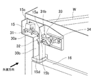
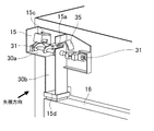
図6は、本発明の実施例2に係るトナー搬送機構の全体像をとらえた模式的斜視断面図であり、手前側(図中矢印方向とは反対側)におけるトナー搬出ダクト部15の壁部分や装置本体1の外壁カバー等を取り除いて内部構造を見やすく示している。
図7は、図6の矢視方向から見た内部断面を拡大した模式図であり、トナー搬出ダクト15内の各部品の動きを説明するための図である。
FIG. 6 is a schematic perspective cross-sectional view of the toner transport mechanism according to the second embodiment of the present invention, and is a wall portion of the toner carry-out
FIG. 7 is an enlarged schematic view of an internal cross section seen from the direction of arrow in FIG. 6, and is a diagram for explaining the movement of each component in the toner carry-out
図6に示すように、トナー搬出ダクト15は、トナーを搬送するための搬送路30を持ち、その内部に搬送スクリュ31と詰まり検知レバー32が設置されている。また、トナー搬出ダクト15の搬送路30は、搬送スクリュ31によってトナーが略水平方向に搬送される搬送路30aとその下流に位置し、トナーが自由落下する搬送路30bと、で構成されている。トナー排出ダクト15は、搬送スクリュ31が挿通される軸孔15a、トナー搬送機構Wから搬送されるトナーを受け入れる開口部15c、トナー回収容器16と連通する開口部15d、詰まり検知レバー35が配置される開口部15e、を有する。トナー排出ダクト15は、図では内部を開放して示しているが、上記軸孔15a、開口部15c、15d、15e以外は壁で覆われており、開口部15cから開口部15dまで略逆L字形のトナー搬送路30を形成している。
As shown in FIG. 6, the toner carry-out
搬送スクリュ31は、不図示の駆動源から駆動力を伝達されることで一方向へ回転することが可能であり、回転すること搬送スクリュ31の羽根部31aがトナーを押し、トナーを略水平方向下流側へと搬送することができる。
The
搬送路30aと搬送路30bの接続部にて、搬送スクリュ31よりも上方に詰まり検知レバー32が設置されている。詰まり検知レバー35は、トナー被押圧部35aとフラグ形状をしたレバー部(フラグ部)35bを持ち、回転軸35cを中心に回転可能にトナー搬出ダクト15に設けられている。
At the connection portion between the
図7を用いて、詰まり検知レバー35の動きについて説明する。
図7(a)に示すように、詰まり検知レバー35は、トナーが正常に搬送されている通常使用時には、トナーが搬送される領域から外れた退避位置にある。すなわち、トナーが正常に搬送されている状態においては、搬送スクリュ31の回転により搬送されるトナーの多くは、飛散、浮遊しているトナーを除き、搬送スクリュ31が回転している領域内において搬送路30aを搬送される。したがって、搬送スクリュ31よりも上方に配置されている詰まり検知レバー35は、トナーの搬送領域から外れた位置にあることになる。この退避位置にある状態において詰まり検知レバー35は、搬送スクリュ31によりトナーが搬送路30内を搬送される際においてその動きを阻害しない。
The movement of the clogging
As shown in FIG. 7A, the clogging
図7(b)に示すように、詰まり検知レバー35より下流側のトナー回収装置16の不具合等で搬送路30bが詰まり、トナーが上方に積み上がってくる場合がある。この場合には、詰まり検知レバー35のトナー被押圧部35aがトナーによって押され、回転軸35cを中心に移動する。詰まり検知レバー35のレバー部35bは、検知センサ34近傍に位置するように設置されている。詰まり検知レバー35は、通常状態ではレバー部35bが検知センサ34の透光位置(検知センサ34の検知光を遮らない非遮光位置)となる回転位相を維持するように設置されている。下流側のトナー詰まりによってトナー被押圧
部35aが矢印A方向に押し上げられると、詰まり検知レバー35は、レバー部35bが図7(b)に示すように検知センサ34の検知光を遮光する遮光位置となるように回転する。レバー部35bが遮光位置となる回転位相になると、堆積したトナーが取り除かれない限り、詰まり検知レバー35はその位置(回転位相)から動かなくなる。
As shown in FIG. 7B, the
検知センサ34は、詰まり検知レバー35のレバー部35bによって遮光される状態(受光部が検知光を受光しない非受光状態)が一定時間続いた場合(所定の閾値時間を超えて継続した場合)に、異常を検知するように制御されている。正常にトナーが搬送されている状態であっても、トナーの搬送量によってはトナー被押圧部35aがトナーに押されて詰まり検知レバー35が回転し、レバー部35bが瞬間的に、あるいは極短時間の間、遮光位置に移動することが考えられる。そのようなイレギュラーな遮光状態を誤って異常として検知してしまうことを防止するため、遮光状態が一定時間以上続いた場合に、異常検知するように構成している。
The
<シール構成>
本実施例に係るトナー搬送機構は、故障検知手段の誤検知を防止するため、具体的には、検知センサ34にトナーが付着して検知精度に影響を及ぼすことを防止するため、次のようなシール構成を採用している。
まず、検知センサ34を、トナー搬出ダクト15の外部に配置している。すなわち、故障検知手段の構成において、トナーとの接触が好ましくない構成である検知センサ34を、トナーを搬送する搬送路の外側に配置している。
<Seal configuration>
The toner transfer mechanism according to the present embodiment is as follows in order to prevent erroneous detection of the failure detection means, specifically, to prevent toner from adhering to the
First, the
また、詰まり検知レバー35を、搬送スクリュ31よりも上方に位置する開口部15eを介して、トナー搬出ダクト15の内部と外部とにまたがるように設けている。開口部15eは搬送スクリュ31よりも上方に位置しており、搬送スクリュ31の回転によって搬送されるトナーのほとんどは、開口部15eよりも下方を移動する。すなわち、通常のトナー搬送時には、トナーが移動することない領域に開口部15eが設けられている。開口部15eと詰まり検知レバー35との間には詰まり検知レバー35の動作を妨げないように隙間が設けられており、搬送されるトナーの一部が飛散、浮遊して開口部15eを介して漏れ出る可能性がある。しかしながら、そのようにして漏れ出るトナーの量は極僅かであり、開口部15eからのトナー漏れが検知センサ34の検知に影響を及ぼすような状況では、既に詰まり検知レバー35が作動している(詰まり検知レバー35が作動すべき状況)と考えられる。また、開口部15eには、詰まり検知レバー35が配置されており、搬送されるトナーの一部が飛散、浮遊していたとしても、詰まり検知レバー35に阻まれることでそれらトナーが検知センサ34まで容易に到達することはない。したがって、開口部15eと詰まり検知レバー35との間に隙間があっても支障はなく、故障検知と誤検知防止を簡易な構成で実現することができる。
Further, the clogging
図10は、実施例2の変形例におけるシール構成を説明する模式的断面図である。検知センサ34の誤検知防止をさらに万全とすべく、図10に示すように構成してもよい。すなわち、詰まり検知レバー35の回転軸35cの位置を開口部15eに合わせて、回転軸35cと開口部15eとの間を回転軸35cと摺動接触するシール部材19でシールして、検知センサ34の誤検知防止を万全にしてもよい。
FIG. 10 is a schematic cross-sectional view illustrating a seal configuration in a modified example of the second embodiment. In order to further prevent false detection of the
以上のように、途中で搬送路30の搬送方向が切り替わるトナー搬出ダクト15内の搬送方向と離れた箇所に詰まり検知レバー35を設置し、その外部に詰まり検知レバー35を検知できる検知センサ34を設置している。これにより、検知センサ34にトナーが付着して検知精度を損ねることを防止し、かつシール部材のサイズ、構成点数を最小限に抑えることができる。
As described above, the clogging
なお、本発明のトナー搬送機構は、本実施例で示したカラーレーザビームプリンタのトナー搬出ダクト部に適用範囲が限られるものではない。粉体を搬送する搬送路において同様の部品を設置可能であれば、画像形成装置における種々の構成に対して適用することができる。 The range of application of the toner transfer mechanism of the present invention is not limited to the toner carry-out duct portion of the color laser beam printer shown in this embodiment. If similar parts can be installed in the transport path for transporting the powder, it can be applied to various configurations in the image forming apparatus.
15…トナー搬出ダクト、16…トナー回収容器、30…トナー搬送路、31…搬送スクリュ、31b…カム部、32…詰まり検知レバー、32a…トナー被押圧部、32b…レバー部、32c…回転軸、33…中間検知フラグ、33a…端部フラグ形状部、34…検知センサ 15 ... Toner carry-out duct, 16 ... Toner collection container, 30 ... Toner transport path, 31 ... Transport screw, 31b ... Cam section, 32 ... Clog detection lever, 32a ... Toner pressed section, 32b ... Lever section, 32c ... Rotating shaft , 33 ... Intermediate detection flag, 33a ... End flag shape part, 34 ... Detection sensor
Claims (8)
トナーを搬送するための搬送路を形成するダクトと、
前記搬送路に設けられた、回転することにより前記搬送路内のトナーを搬送する搬送部材と、
前記ダクトの外側に配置された、第1の検知状態と第2の検知状態とを取り得るセンサと、
前記搬送路内のトナーの量に応じて変位する第1可動部材と、
前記搬送部材の回転に応じて変位する第2可動部材と、
前記第2可動部材に押圧されることによって、前記センサが前記第1の検知状態となるように前記センサに作用する第1位置と、前記センサが前記第2の検知状態となるように前記センサに作用する第2位置と、に移動するフラグ部材であって、前記第1可動部材と接触することで前記搬送部材の回転に関わらず前記第1位置に位置決めされるフラグ部材と、
を有し、
前記フラグ部材は、前記第2可動部材に接触した状態において前記第1可動部材から離れており、前記第1可動部材と接触することで前記第2可動部材と離れることを特徴とするトナー搬送機構。 It is a toner transfer mechanism
A duct that forms a transport path for transporting toner,
A transport member provided in the transport path that transports toner in the transport path by rotation, and a transport member.
A sensor arranged outside the duct that can take a first detection state and a second detection state ,
A first movable member that displaces according to the amount of toner in the transport path, and
A second movable member that displaces according to the rotation of the transport member, and
The first position that acts on the sensor so that the sensor is in the first detection state by being pressed by the second movable member, and the sensor so that the sensor is in the second detection state. A flag member that moves to a second position that acts on, and that is positioned at the first position by contacting the first movable member regardless of the rotation of the transport member .
Have a,
The toner transport mechanism is characterized in that the flag member is separated from the first movable member in a state of being in contact with the second movable member, and is separated from the second movable member by being in contact with the first movable member. ..
前記センサは、前記第1の検知状態が所定の時間を超えて継続したときに、トナー搬送機構の異常を検知することを特徴とする請求項1に記載のトナー搬送機構。 When the amount of toner deposited in the transport path exceeds a predetermined amount, the first movable member presses the flag member so as to move the flag member from the second position to the first position. Has one pressing part,
The toner transfer mechanism according to claim 1, wherein the sensor detects an abnormality in the toner transfer mechanism when the first detection state continues for a predetermined time.
前記第1可動部材は、前記第2搬送路に堆積したトナーに押圧される被押圧部を前記第2搬送路内に有し、前記第1押圧部を前記ダクトの外側に有し、前記被押圧部がトナーに押圧されると前記第1押圧部が前記フラグ部材を押圧する状態となるように回転すること
を特徴とする請求項2に記載のトナー搬送機構。 The transport path includes a first transport path that extends substantially horizontally and a second transport path that extends downward from the downstream of the first transport path.
The first movable member has a pressed portion pressed by the toner deposited on the second transport path in the second transport path, the first pressing portion on the outside of the duct, and the pressed portion. The toner transport mechanism according to claim 2, wherein when the pressing portion is pressed by the toner, the first pressing portion rotates so as to press the flag member.
前記センサは、前記第1の検知状態または前記第2の検知状態が所定の時間を超えて継続したときに、トナー搬送機構の異常を検知することを特徴とする請求項1〜4のいずれか1項に記載のトナー搬送機構。 The second movable member presses the flag member so as to periodically and alternately move the flag member between the first position and the second position while the transport member is rotating. Has a pressing part,
Any of claims 1 to 4, wherein the sensor detects an abnormality in the toner transport mechanism when the first detection state or the second detection state continues for a predetermined time. The toner transfer mechanism according to item 1.
前記搬送部材は、前記第1搬送路に沿って延びるスクリュであり、
前記第2可動部材は、前記第1搬送路の下流において前記ダクトの外部に延びる前記スクリュの軸の端部に設けられたカム部材であり、前記第2押圧部としてのカム面を有し、前記スクリュの回転によって回転することを特徴とする請求項5に記載のトナー搬送機構。 The transport path includes a first transport path that extends substantially horizontally and a second transport path that extends downward from the downstream of the first transport path.
The transport member is a screw extending along the first transport path.
The second movable member is a cam member provided at the end of the shaft of the screw extending to the outside of the duct downstream of the first transport path, and has a cam surface as the second pressing portion. The toner transfer mechanism according to claim 5, wherein the toner is rotated by rotation of the screw.
前記フラグ部材は、前記第1位置として前記光学センサの検知光を遮る位置と、前記第2位置として前記検知光を遮らない位置と、に移動することを特徴とする請求項1〜6のいずれか1項に記載のトナー搬送機構。 The sensor is an optical sensor and
The flag member is any of claims 1 to 6 , wherein the flag member moves to a position where the detection light of the optical sensor is blocked as the first position and a position where the detection light is not blocked as the second position. The toner transport mechanism according to item 1.
記録材に転写されずに残ったトナーを回収容器に搬送する請求項1〜7のいずれか1項に記載のトナー搬送機構と、
を備えることを特徴とする画像形成装置。
An image forming unit that forms an image on the recording material by transferring and fixing the toner image on the recording material,
The toner transfer mechanism according to any one of claims 1 to 7 , wherein the toner remaining without being transferred to the recording material is transferred to the collection container.
An image forming apparatus comprising.
Priority Applications (4)
| Application Number | Priority Date | Filing Date | Title |
|---|---|---|---|
| JP2017077494A JP6942507B2 (en) | 2017-04-10 | 2017-04-10 | Toner transfer mechanism and image forming device |
| US15/944,073 US10261457B2 (en) | 2017-04-10 | 2018-04-03 | Toner transport mechanism and image forming apparatus |
| CN201810314653.5A CN108693754A (en) | 2017-04-10 | 2018-04-10 | Toner carrying mechanism and image forming apparatus |
| US16/291,546 US10488803B2 (en) | 2017-04-10 | 2019-03-04 | Toner transport mechanism and image forming apparatus |
Applications Claiming Priority (1)
| Application Number | Priority Date | Filing Date | Title |
|---|---|---|---|
| JP2017077494A JP6942507B2 (en) | 2017-04-10 | 2017-04-10 | Toner transfer mechanism and image forming device |
Publications (3)
| Publication Number | Publication Date |
|---|---|
| JP2018180180A JP2018180180A (en) | 2018-11-15 |
| JP2018180180A5 JP2018180180A5 (en) | 2020-05-21 |
| JP6942507B2 true JP6942507B2 (en) | 2021-09-29 |
Family
ID=63711583
Family Applications (1)
| Application Number | Title | Priority Date | Filing Date |
|---|---|---|---|
| JP2017077494A Active JP6942507B2 (en) | 2017-04-10 | 2017-04-10 | Toner transfer mechanism and image forming device |
Country Status (3)
| Country | Link |
|---|---|
| US (2) | US10261457B2 (en) |
| JP (1) | JP6942507B2 (en) |
| CN (1) | CN108693754A (en) |
Families Citing this family (1)
| Publication number | Priority date | Publication date | Assignee | Title |
|---|---|---|---|---|
| JP7009145B2 (en) | 2017-09-29 | 2022-01-25 | キヤノン株式会社 | Image forming device |
Family Cites Families (18)
| Publication number | Priority date | Publication date | Assignee | Title |
|---|---|---|---|---|
| JP2001215854A (en) * | 2000-01-28 | 2001-08-10 | Kyocera Corp | Electrophotographic device |
| JP3771880B2 (en) * | 2002-08-12 | 2006-04-26 | 株式会社沖データ | Toner recovery device |
| US7085507B2 (en) * | 2003-08-25 | 2006-08-01 | Lexmark International, Inc. | Method and apparatus to control waste toner collection in an image forming apparatus |
| JP4578871B2 (en) * | 2004-04-01 | 2010-11-10 | 株式会社沖データ | Developer collection container and image forming apparatus |
| JP2009063772A (en) * | 2007-09-05 | 2009-03-26 | Ricoh Co Ltd | Image forming device |
| JP5267012B2 (en) * | 2008-09-29 | 2013-08-21 | 株式会社リコー | Waste toner collecting container, cleaning unit, and image forming apparatus |
| JP5413729B2 (en) * | 2009-01-30 | 2014-02-12 | 株式会社リコー | Powder container and image forming apparatus |
| JP4811492B2 (en) * | 2009-03-31 | 2011-11-09 | ブラザー工業株式会社 | Image forming apparatus |
| US8249471B2 (en) | 2009-03-31 | 2012-08-21 | Brother Kogyo Kabushiki Kaisha | Image forming apparatus having waste toner detecting mechanism |
| JP2011033693A (en) | 2009-07-30 | 2011-02-17 | Brother Industries Ltd | Image forming apparatus |
| US8600246B2 (en) * | 2010-06-25 | 2013-12-03 | Sharp Kabushiki Kaisha | Developer recovery device and image forming apparatus including same |
| JP2012008382A (en) * | 2010-06-25 | 2012-01-12 | Sharp Corp | Developer collecting device and image forming apparatus therewith |
| JP5803331B2 (en) * | 2011-06-27 | 2015-11-04 | ブラザー工業株式会社 | Toner container and image forming apparatus |
| JP2013120320A (en) * | 2011-12-08 | 2013-06-17 | Ricoh Co Ltd | Powder recovery device and image forming apparatus |
| JP6094174B2 (en) * | 2012-11-28 | 2017-03-15 | 株式会社リコー | Toner recovery apparatus and image forming apparatus having the same |
| JP6693046B2 (en) * | 2015-04-06 | 2020-05-13 | コニカミノルタ株式会社 | Toner collecting device and image forming device |
| JP6594069B2 (en) | 2015-07-08 | 2019-10-23 | キヤノン株式会社 | Container and image forming apparatus |
| JP6561711B2 (en) * | 2015-09-15 | 2019-08-21 | コニカミノルタ株式会社 | Image forming apparatus |
-
2017
- 2017-04-10 JP JP2017077494A patent/JP6942507B2/en active Active
-
2018
- 2018-04-03 US US15/944,073 patent/US10261457B2/en active Active
- 2018-04-10 CN CN201810314653.5A patent/CN108693754A/en active Pending
-
2019
- 2019-03-04 US US16/291,546 patent/US10488803B2/en active Active
Also Published As
| Publication number | Publication date |
|---|---|
| CN108693754A (en) | 2018-10-23 |
| US20180292777A1 (en) | 2018-10-11 |
| US20190196384A1 (en) | 2019-06-27 |
| US10488803B2 (en) | 2019-11-26 |
| JP2018180180A (en) | 2018-11-15 |
| US10261457B2 (en) | 2019-04-16 |
Similar Documents
| Publication | Publication Date | Title |
|---|---|---|
| JP4862932B2 (en) | Toner bottle and image forming apparatus having the same | |
| JP2008116479A (en) | Image forming apparatus | |
| JP5118545B2 (en) | Image forming apparatus | |
| JP2006085112A (en) | Waste toner recovery container and image forming apparatus | |
| JP2007304192A (en) | Image forming apparatus | |
| JP5933516B2 (en) | Cleaning device, image forming device | |
| JP5100897B2 (en) | Image forming apparatus | |
| JP6942507B2 (en) | Toner transfer mechanism and image forming device | |
| US20190049889A1 (en) | Image forming apparatus | |
| JP6218525B2 (en) | Image forming apparatus | |
| JP2007309991A (en) | Image forming apparatus | |
| JP4951115B2 (en) | Image forming apparatus | |
| US10539917B2 (en) | Container and image forming apparatus | |
| KR20210115175A (en) | Waste toner collecting for preventing full detection error | |
| JP2005315953A (en) | Color image forming apparatus | |
| JP4586398B2 (en) | Image forming apparatus | |
| JP4711815B2 (en) | Paper feeding device and image forming apparatus using the paper feeding device | |
| US9541890B2 (en) | Image forming apparatus | |
| JP6369401B2 (en) | Image forming apparatus | |
| JP2006139151A (en) | Image forming apparatus | |
| JP2019197103A (en) | Waste toner recovery container and image forming apparatus | |
| JP2010224284A (en) | Waste toner recovery device, and image forming apparatus | |
| JP6191383B2 (en) | Image forming apparatus | |
| JPH10153939A (en) | Image forming device | |
| JP2023178808A (en) | Image formation device |
Legal Events
| Date | Code | Title | Description |
|---|---|---|---|
| RD02 | Notification of acceptance of power of attorney |
Free format text: JAPANESE INTERMEDIATE CODE: A7422 Effective date: 20181116 |
|
| A521 | Written amendment |
Free format text: JAPANESE INTERMEDIATE CODE: A523 Effective date: 20200403 |
|
| A621 | Written request for application examination |
Free format text: JAPANESE INTERMEDIATE CODE: A621 Effective date: 20200403 |
|
| A977 | Report on retrieval |
Free format text: JAPANESE INTERMEDIATE CODE: A971007 Effective date: 20210224 |
|
| A131 | Notification of reasons for refusal |
Free format text: JAPANESE INTERMEDIATE CODE: A131 Effective date: 20210309 |
|
| A521 | Written amendment |
Free format text: JAPANESE INTERMEDIATE CODE: A523 Effective date: 20210507 |
|
| TRDD | Decision of grant or rejection written | ||
| A01 | Written decision to grant a patent or to grant a registration (utility model) |
Free format text: JAPANESE INTERMEDIATE CODE: A01 Effective date: 20210810 |
|
| A61 | First payment of annual fees (during grant procedure) |
Free format text: JAPANESE INTERMEDIATE CODE: A61 Effective date: 20210908 |
|
| R151 | Written notification of patent or utility model registration |
Ref document number: 6942507 Country of ref document: JP Free format text: JAPANESE INTERMEDIATE CODE: R151 |