JP6942451B2 - Image forming apparatus, image forming system, information processing apparatus, image forming apparatus or control method of information processing apparatus, program and storage medium - Google Patents
Image forming apparatus, image forming system, information processing apparatus, image forming apparatus or control method of information processing apparatus, program and storage medium Download PDFInfo
- Publication number
- JP6942451B2 JP6942451B2 JP2016171884A JP2016171884A JP6942451B2 JP 6942451 B2 JP6942451 B2 JP 6942451B2 JP 2016171884 A JP2016171884 A JP 2016171884A JP 2016171884 A JP2016171884 A JP 2016171884A JP 6942451 B2 JP6942451 B2 JP 6942451B2
- Authority
- JP
- Japan
- Prior art keywords
- bookbinding
- die
- image forming
- binding member
- processing
- Prior art date
- Legal status (The legal status is an assumption and is not a legal conclusion. Google has not performed a legal analysis and makes no representation as to the accuracy of the status listed.)
- Active
Links
Images


Classifications
-
- G—PHYSICS
- G06—COMPUTING; CALCULATING OR COUNTING
- G06F—ELECTRIC DIGITAL DATA PROCESSING
- G06F3/00—Input arrangements for transferring data to be processed into a form capable of being handled by the computer; Output arrangements for transferring data from processing unit to output unit, e.g. interface arrangements
- G06F3/12—Digital output to print unit, e.g. line printer, chain printer
- G06F3/1201—Dedicated interfaces to print systems
- G06F3/1202—Dedicated interfaces to print systems specifically adapted to achieve a particular effect
- G06F3/1203—Improving or facilitating administration, e.g. print management
- G06F3/1205—Improving or facilitating administration, e.g. print management resulting in increased flexibility in print job configuration, e.g. job settings, print requirements, job tickets
-
- B—PERFORMING OPERATIONS; TRANSPORTING
- B42—BOOKBINDING; ALBUMS; FILES; SPECIAL PRINTED MATTER
- B42C—BOOKBINDING
- B42C1/00—Collating or gathering sheets combined with processes for permanently attaching together sheets or signatures or for interposing inserts
- B42C1/12—Machines for both collating or gathering and permanently attaching together the sheets or signatures
-
- B—PERFORMING OPERATIONS; TRANSPORTING
- B42—BOOKBINDING; ALBUMS; FILES; SPECIAL PRINTED MATTER
- B42C—BOOKBINDING
- B42C19/00—Multi-step processes for making books
- B42C19/02—Multi-step processes for making books starting with single sheets
-
- B—PERFORMING OPERATIONS; TRANSPORTING
- B65—CONVEYING; PACKING; STORING; HANDLING THIN OR FILAMENTARY MATERIAL
- B65H—HANDLING THIN OR FILAMENTARY MATERIAL, e.g. SHEETS, WEBS, CABLES
- B65H37/00—Article or web delivery apparatus incorporating devices for performing specified auxiliary operations
- B65H37/04—Article or web delivery apparatus incorporating devices for performing specified auxiliary operations for securing together articles or webs, e.g. by adhesive, stitching or stapling
-
- G—PHYSICS
- G06—COMPUTING; CALCULATING OR COUNTING
- G06F—ELECTRIC DIGITAL DATA PROCESSING
- G06F3/00—Input arrangements for transferring data to be processed into a form capable of being handled by the computer; Output arrangements for transferring data from processing unit to output unit, e.g. interface arrangements
- G06F3/12—Digital output to print unit, e.g. line printer, chain printer
- G06F3/1201—Dedicated interfaces to print systems
- G06F3/1202—Dedicated interfaces to print systems specifically adapted to achieve a particular effect
- G06F3/121—Facilitating exception or error detection and recovery, e.g. fault, media or consumables depleted
-
- G—PHYSICS
- G06—COMPUTING; CALCULATING OR COUNTING
- G06F—ELECTRIC DIGITAL DATA PROCESSING
- G06F3/00—Input arrangements for transferring data to be processed into a form capable of being handled by the computer; Output arrangements for transferring data from processing unit to output unit, e.g. interface arrangements
- G06F3/12—Digital output to print unit, e.g. line printer, chain printer
- G06F3/1201—Dedicated interfaces to print systems
- G06F3/1223—Dedicated interfaces to print systems specifically adapted to use a particular technique
- G06F3/1229—Printer resources management or printer maintenance, e.g. device status, power levels
- G06F3/1234—Errors handling and recovery, e.g. reprinting
-
- G—PHYSICS
- G06—COMPUTING; CALCULATING OR COUNTING
- G06F—ELECTRIC DIGITAL DATA PROCESSING
- G06F3/00—Input arrangements for transferring data to be processed into a form capable of being handled by the computer; Output arrangements for transferring data from processing unit to output unit, e.g. interface arrangements
- G06F3/12—Digital output to print unit, e.g. line printer, chain printer
- G06F3/1201—Dedicated interfaces to print systems
- G06F3/1223—Dedicated interfaces to print systems specifically adapted to use a particular technique
- G06F3/1236—Connection management
-
- G—PHYSICS
- G06—COMPUTING; CALCULATING OR COUNTING
- G06F—ELECTRIC DIGITAL DATA PROCESSING
- G06F3/00—Input arrangements for transferring data to be processed into a form capable of being handled by the computer; Output arrangements for transferring data from processing unit to output unit, e.g. interface arrangements
- G06F3/12—Digital output to print unit, e.g. line printer, chain printer
- G06F3/1201—Dedicated interfaces to print systems
- G06F3/1223—Dedicated interfaces to print systems specifically adapted to use a particular technique
- G06F3/1237—Print job management
- G06F3/1253—Configuration of print job parameters, e.g. using UI at the client
- G06F3/1255—Settings incompatibility, e.g. constraints, user requirements vs. device capabilities
-
- G—PHYSICS
- G06—COMPUTING; CALCULATING OR COUNTING
- G06F—ELECTRIC DIGITAL DATA PROCESSING
- G06F3/00—Input arrangements for transferring data to be processed into a form capable of being handled by the computer; Output arrangements for transferring data from processing unit to output unit, e.g. interface arrangements
- G06F3/12—Digital output to print unit, e.g. line printer, chain printer
- G06F3/1201—Dedicated interfaces to print systems
- G06F3/1278—Dedicated interfaces to print systems specifically adapted to adopt a particular infrastructure
- G06F3/1285—Remote printer device, e.g. being remote from client or server
- G06F3/1286—Remote printer device, e.g. being remote from client or server via local network
-
- G—PHYSICS
- G06—COMPUTING; CALCULATING OR COUNTING
- G06F—ELECTRIC DIGITAL DATA PROCESSING
- G06F3/00—Input arrangements for transferring data to be processed into a form capable of being handled by the computer; Output arrangements for transferring data from processing unit to output unit, e.g. interface arrangements
- G06F3/12—Digital output to print unit, e.g. line printer, chain printer
- G06F3/1293—Printer information exchange with computer
-
- G—PHYSICS
- G06—COMPUTING; CALCULATING OR COUNTING
- G06K—GRAPHICAL DATA READING; PRESENTATION OF DATA; RECORD CARRIERS; HANDLING RECORD CARRIERS
- G06K15/00—Arrangements for producing a permanent visual presentation of the output data, e.g. computer output printers
- G06K15/002—Interacting with the operator
-
- G—PHYSICS
- G06—COMPUTING; CALCULATING OR COUNTING
- G06K—GRAPHICAL DATA READING; PRESENTATION OF DATA; RECORD CARRIERS; HANDLING RECORD CARRIERS
- G06K15/00—Arrangements for producing a permanent visual presentation of the output data, e.g. computer output printers
- G06K15/40—Details not directly involved in printing, e.g. machine management, management of the arrangement as a whole or of its constitutive parts
- G06K15/4025—Managing optional units, e.g. sorters, document feeders
- G06K15/403—Managing optional units, e.g. sorters, document feeders handling the outputted documents, e.g. staplers, sorters
- G06K15/404—Managing other optional outputs, e.g. collators, staplers
-
- G—PHYSICS
- G06—COMPUTING; CALCULATING OR COUNTING
- G06K—GRAPHICAL DATA READING; PRESENTATION OF DATA; RECORD CARRIERS; HANDLING RECORD CARRIERS
- G06K15/00—Arrangements for producing a permanent visual presentation of the output data, e.g. computer output printers
- G06K15/40—Details not directly involved in printing, e.g. machine management, management of the arrangement as a whole or of its constitutive parts
- G06K15/408—Handling exceptions, e.g. faults
-
- B—PERFORMING OPERATIONS; TRANSPORTING
- B65—CONVEYING; PACKING; STORING; HANDLING THIN OR FILAMENTARY MATERIAL
- B65H—HANDLING THIN OR FILAMENTARY MATERIAL, e.g. SHEETS, WEBS, CABLES
- B65H2301/00—Handling processes for sheets or webs
- B65H2301/40—Type of handling process
- B65H2301/43—Gathering; Associating; Assembling
- B65H2301/438—Finishing
- B65H2301/4382—Binding or attaching processes
-
- B—PERFORMING OPERATIONS; TRANSPORTING
- B65—CONVEYING; PACKING; STORING; HANDLING THIN OR FILAMENTARY MATERIAL
- B65H—HANDLING THIN OR FILAMENTARY MATERIAL, e.g. SHEETS, WEBS, CABLES
- B65H2402/00—Constructional details of the handling apparatus
- B65H2402/10—Modular constructions, e.g. using preformed elements or profiles
-
- B—PERFORMING OPERATIONS; TRANSPORTING
- B65—CONVEYING; PACKING; STORING; HANDLING THIN OR FILAMENTARY MATERIAL
- B65H—HANDLING THIN OR FILAMENTARY MATERIAL, e.g. SHEETS, WEBS, CABLES
- B65H2601/00—Problem to be solved or advantage achieved
- B65H2601/30—Facilitating or easing
- B65H2601/32—Facilitating or easing entities relating to handling machine
- B65H2601/324—Removability or inter-changeability of machine parts, e.g. for maintenance
-
- B—PERFORMING OPERATIONS; TRANSPORTING
- B65—CONVEYING; PACKING; STORING; HANDLING THIN OR FILAMENTARY MATERIAL
- B65H—HANDLING THIN OR FILAMENTARY MATERIAL, e.g. SHEETS, WEBS, CABLES
- B65H2801/00—Application field
- B65H2801/24—Post -processing devices
- B65H2801/27—Devices located downstream of office-type machines
-
- G—PHYSICS
- G06—COMPUTING; CALCULATING OR COUNTING
- G06F—ELECTRIC DIGITAL DATA PROCESSING
- G06F3/00—Input arrangements for transferring data to be processed into a form capable of being handled by the computer; Output arrangements for transferring data from processing unit to output unit, e.g. interface arrangements
- G06F3/12—Digital output to print unit, e.g. line printer, chain printer
- G06F3/1201—Dedicated interfaces to print systems
- G06F3/1202—Dedicated interfaces to print systems specifically adapted to achieve a particular effect
- G06F3/1203—Improving or facilitating administration, e.g. print management
- G06F3/1207—Improving or facilitating administration, e.g. print management resulting in the user being informed about print result after a job submission
Description
本発明は、画像形成装置、画像形成システム、情報処理装置、画像形成装置又は情報処理装置の制御方法及びプログラム及び記憶媒体に関するものである。 The present invention relates to an image forming apparatus, an image forming system, an information processing apparatus, an image forming apparatus or a control method of the information processing apparatus, a program, and a storage medium.
従来、画像形成装置が実行可能な後処理機能の一つとして、印刷された複数の用紙を整合し、とじる若しくは糊付け加工を施すことによって製本成果物を作成可能な製本機能が知られている。一例として、針(ステイプル)によって整合状態の用紙束の中央部をとじ、かつ針に沿って折り加工を行うサドル製本機能が挙げられる。また別の一例として、整合状態の用紙端部に糊付け加工を施すことによって製本成果物を得るくるみ製本機能が挙げられる。さらに別の一例として、用紙の端部に穿孔(パンチ)処理を施し、該穿孔処理によって穿孔された箇所にリング状の綴じ部材を差し込むことに依って用紙を束ねることにより製本成果物を得る処理が挙げられる。この処理は綴じ処理に用いる綴じ部材の形状から、ワイヤ製本機能やリング製本機能などと呼ばれる。 Conventionally, as one of the post-processing functions that can be executed by an image forming apparatus, a bookbinding function that can create a bookbinding product by aligning, binding, or gluing a plurality of printed sheets is known. One example is a saddle bookbinding function that binds the central portion of a bundle of paper in a aligned state with a needle (staple) and folds along the needle. Another example is a wrapped bookbinding function that obtains a bookbinding product by gluing the edges of the aligned paper. As yet another example, a process of punching the edges of the paper and bundling the paper by inserting a ring-shaped binding member into the punched portion of the paper to obtain a bookbinding product. Can be mentioned. This process is called a wire binding function or a ring binding function because of the shape of the binding member used in the binding process.
リング製本機能によってとじる方法としては、例えば予め定められたサイズのプラスチック等により形成された綴じ部材を穿孔加工処理後の用紙束の穴部に差し込む事によって製本成果物を得る形態のものが知られている。またはワイヤ製本機能によってとじる方法としては、例えば金属等の素材により構成され、任意の長さでカットした綴じ部材を、穿孔加工が施された用紙束の穴部に差し込み、曲げ加工を行うことによって行う様式のワイヤ製本処理が知られている。これらは使用する綴じ部材は異なるものの工程は共通しているため、以下ではまとめてワイヤ製本機能と呼ぶ。また、ステイプルなどによるとじ工程と区別するため、本実施形態で述べるとじ工程をワイヤ綴じと呼称する。 As a method of binding by the ring bookbinding function, for example, a method of obtaining a bookbinding product by inserting a binding member formed of a predetermined size plastic or the like into a hole of a paper bundle after a perforation process is known. ing. Alternatively, as a method of binding by the wire binding function, for example, a binding member made of a material such as metal and cut to an arbitrary length is inserted into a hole of a perforated paper bundle and bent. The style of wire binding is known. Although they use different binding members, they have the same process, so they are collectively referred to as the wire binding function below. Further, in order to distinguish it from the binding process using staples or the like, the binding process described in this embodiment is referred to as wire binding.
ワイヤ製本機能では印刷を行う工程と、穿孔加工を行う工程、とじる工程が別々の装置でシーケンシャルに行われため、上流の工程に合わせて、下流の工程を適切に制御する必要がある。例えば、特許文献1では使用される用紙に穿孔加工が既に実施されている場合、印刷工程を行う画像形成装置が穿孔加工を行わないように穿孔装置を制御する方法が記載されている。
また、適切な穿孔器具が装着されていない場合、穿孔処理がされないまま、用紙が下流側機器に排出される後処理装置も知られている。
In the wire binding function, the printing process, the punching process, and the binding process are sequentially performed by separate devices, so it is necessary to appropriately control the downstream process according to the upstream process. For example, Patent Document 1 describes a method of controlling a perforation device so that an image forming apparatus performing a printing process does not perform perforation processing when the paper to be used has already been perforated.
There is also known a post-treatment device in which paper is discharged to a downstream device without being perforated if a suitable perforation device is not attached.
前述の通り、ワイヤ製本機能では印刷工程、穿孔加工、とじ工程がシーケンシャルに実施されるため上流の工程が適切に実施されなかった場合、下流の工程を実施する事ができない。穿孔加工でとじ工程に合った適切な形状、穴数、穴の間隔の穿孔器具(ダイ(die))を用いて処理が行われなければ綴じ工程を行うことが出来ないが、穿孔器具はいつでも容易に交換が可能であり、種類が多数存在するため、操作者が常に適切な器具が装着されているかを把握しておくことは難しいという課題があった。
一方、ワイヤ製本処理を実行する場合、製本、穿孔等の処理を行う別装置を画像形成装置に接続して行う画像形成システムとして構成される場合も、同様の課題を有する。
さらには、PC等から受信する印刷ジョブを画像形成装置に送信する情報処理装置を使用する場合も、同様の課題を有する。
As described above, in the wire bookbinding function, the printing process, the punching process, and the binding process are sequentially performed. Therefore, if the upstream process is not properly performed, the downstream process cannot be performed. The binding process cannot be performed unless the perforation process is performed using a perforation device (die) with an appropriate shape, number of holes, and hole spacing suitable for the binding process, but the perforation device is always available. Since it can be easily replaced and there are many types, it is difficult for the operator to always know whether or not the appropriate equipment is attached.
On the other hand, when the wire bookbinding process is executed, there is a similar problem when the image forming system is configured by connecting another device for performing the bookbinding, perforation, and the like to the image forming apparatus.
Further, when using an information processing device that transmits a print job received from a PC or the like to an image forming device, there is a similar problem.
本発明は、上記の課題を解決するためになされたもので、本発明の目的は、ワイヤ綴じを実行できない状態でワイヤ綴じが指定された印刷ジョブが実行開始されてしまうことを防ぐことが可能となる仕組みを提供することである。 The present invention has been made to solve the above problems, and an object of the present invention is to prevent a print job in which wire binding is specified from being started in a state where wire binding cannot be executed. It is to provide a mechanism to become.
上記目的を達成する本発明の画像形成装置は以下に示す構成を備える。
穿孔されたシートの穴にリング状の綴じ部材が挿入された製本物を生成する製本処理を行う製本装置と、前記製本装置による前記製本処理用である綴じ部材に対応する第1ダイと前記製本装置による前記製本処理用である綴じ部材に対応していない第2ダイとが選択的に装着可能であり、前記第1ダイを用いて前記製本装置で前記綴じ部材が挿入されるべき穴をシートに形成する第1処理と、前記第2ダイを用いた後処理である第2処理とを選択的に行う穿孔装置とを接続可能な画像形成装置であって、印刷設定画面を表示する表示手段と、前記穿孔装置に装着されているダイの種類を示す情報を前記穿孔装置から受信し、該情報に基づいて、前記穿孔装置に装着されているダイが前記第1ダイであるか否かを判断し、前記穿孔装置に装着されているダイが前記第1ダイでない場合、前記印刷設定画面において、前記製本装置を使用する製本設定が選択されないように前記表示手段を制御し、前記穿孔装置に装着されているダイが前記第1ダイである場合、前記印刷設定画面において、前記製本装置を使用する製本設定が選択可能なように前記表示手段を制御する制御手段と、を備えることを特徴とする。
また、本発明の別の画像形成装置は以下に示す構成を備える。
穿孔されたシートの穴にリング状の綴じ部材が挿入された製本物を生成する製本処理を行う製本装置と、前記製本装置による前記製本処理用である綴じ部材に対応する第1ダイと前記製本装置による前記製本処理用である綴じ部材に対応していない第2ダイとが選択的に装着可能であり、前記第1ダイを用いて前記製本装置で前記綴じ部材が挿入されるべき穴をシートに形成する第1処理と、前記第2ダイを用いた後処理である第2処理とを選択的に行う穿孔装置とを接続可能な画像形成装置であって、所定のジョブを受信する受信手段と、受信した前記所定のジョブに前記綴じ部材を用いた前記製本処理を行う指定がなされている場合、前記穿孔装置に装着されているダイの種類を示す情報を前記穿孔装置から受信し、該情報に基づいて、前記穿孔装置に装着されているダイが前記第1ダイであるか否かを判断し、前記穿孔装置に装着されているダイが前記第1ダイでない場合、前記画像形成装置が前記所定のジョブを開始しないよう制御し、ユーザからの前記所定のジョブを中止する指示を受付可能にし、前記指示を受け付けると前記所定のジョブを中止する制御手段と、を備えることを特徴とする。
また、本発明の情報処理装置は以下に示す構成を備える。
穿孔されたシートを積載した後、穿孔された穴にリング状の綴じ部材が挿入された製本物を生成する製本処理を行う製本装置と、前記製本装置による前記製本処理用の綴じ部材に対応する第1パンチダイと前記製本装置による前記製本処理用である綴じ部材に対応していない第2ダイとが選択的に装着可能であり、前記第1パンチダイを用いて前記製本装置で前記綴じ部材が挿入されるべき穴をシートに形成する第1処理と、前記第2ダイを用いた後処理である第2処理とを選択的に行う穿孔装置と、を接続する画像形成装置に印刷ジョブを送信する情報処理装置であって、前記製本物を生成するための製本設定を受け付ける設定画面を表示する表示手段と、前記穿孔装置に装着されているダイが前記第1パンチダイであるか否かを前記画像形成装置から取得する情報に基づいて判断し、前記穿孔装置に装着されているダイが前記第1パンチダイでない場合、前記設定画面を表示しないように前記表示手段を制御し、前記穿孔装置に装着されているダイが前記第1パンチダイである場合、前記設定画面を表示するように前記表示手段を制御する制御手段と、を備えることを特徴とする。
The image forming apparatus of the present invention that achieves the above object has the following configurations.
Wherein the bookbinding apparatus for performing bookbinding processing for generating a bookbinding product binding member hole in a ring-shaped perforated sheet is inserted, a first die corresponding to the binding member the a bookbinding process by the bookbinding device A second die that does not correspond to the binding member for the bookbinding process by the bookbinding device can be selectively mounted, and the first die is used to make a hole in the bookbinding device into which the binding member should be inserted. An image forming apparatus capable of connecting a perforating apparatus that selectively performs a first processing formed on a sheet and a second processing that is a post-processing using the second die, and is a display for displaying a print setting screen. means, information indicating the type of die that is attached to the drilling device and received from the drilling device, based on the information, whether the die that is mounted on the perforation device is the first die When the die mounted on the punching device is not the first die , the display means is controlled so that the bookbinding setting using the bookbinding device is not selected on the print setting screen, and the punching device is used. When the die mounted on the first die is the first die, the print setting screen includes a control means for controlling the display means so that a bookbinding setting using the bookbinding device can be selected. And.
Further, another image forming apparatus of the present invention has the following configuration.
A bookbinding device that produces a bookbinding product in which a ring-shaped binding member is inserted into a hole in a perforated sheet, and a first die and the bookbinding corresponding to the binding member for the bookbinding process by the bookbinding device. A second die that does not correspond to the binding member for the bookbinding process by the device can be selectively mounted, and the first die is used to insert a hole into which the binding member is to be inserted in the bookbinding device. A receiving means for receiving a predetermined job, which is an image forming apparatus capable of connecting a first process formed in the bookbinding device and a perforating device that selectively performs a second process which is a post-processing using the second die. When the received predetermined job is designated to perform the bookbinding process using the binding member, information indicating the type of die mounted on the drilling device is received from the drilling device, and the binding device is used. Based on the information, it is determined whether or not the die mounted on the drilling device is the first die, and if the die mounted on the drilling device is not the first die, the image forming device It is characterized by comprising a control means for controlling not to start the predetermined job, making it possible to accept an instruction from the user to cancel the predetermined job, and canceling the predetermined job when the instruction is received. ..
Further, the information processing apparatus of the present invention has the following configurations.
Corresponds to a bookbinding device that performs a bookbinding process for producing a bookbinding product in which a ring-shaped binding member is inserted into a perforated hole after loading a perforated sheet, and a binding member for the bookbinding process by the bookbinding device. The first punch die and the second die that does not correspond to the binding member for the bookbinding process by the bookbinding device can be selectively mounted, and the binding member is inserted by the bookbinding device using the first punch die. A print job is transmitted to an image forming apparatus that connects a first processing for forming a hole to be bound in a sheet and a perforating apparatus for selectively performing a second processing that is a post-processing using the second die. The image shows a display means for displaying a setting screen for receiving a bookbinding setting for generating the bookbinding device, and whether or not the die mounted on the punching device is the first punch die. When the die mounted on the drilling device is not the first punch die, the display means is controlled so as not to display the setting screen, and the die mounted on the drilling device is mounted on the drilling device. When the die is the first punch die, it is characterized by including a control means for controlling the display means so as to display the setting screen.
本発明によれば、ワイヤ綴じを実行できない状態でワイヤ綴じが指定された印刷ジョブが実行開始されてしまうことを防ぐことができる。 According to the present invention, it is possible to prevent a print job for which wire binding is specified from being started in a state where wire binding cannot be executed.
次に本発明を実施するための最良の形態について図面を参照して説明する。なお、以下の実施の形態は特許請求の範囲に係る発明を限定するものでなく、また実施の形態で説明されている特徴の組み合わせの全てが発明の解決手段に必須のものとは限らない。
<システム構成の説明>
〔第1実施形態〕
Next, the best mode for carrying out the present invention will be described with reference to the drawings. It should be noted that the following embodiments do not limit the invention according to the claims, and not all combinations of features described in the embodiments are essential for the means for solving the invention.
<Explanation of system configuration>
[First Embodiment]
<システム構成の説明> <Explanation of system configuration>
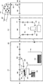
図1は、本実施形態を示すシート後処理装置を有する画像形成システムの構成を示す構成図である。本実施形態では画像形成装置の一例としてMFP(Multi Function Peripheral)101を、印刷ジョブを生成するホスト装置の一例としてPC102を説明する。MFP101とPC102はネットワーク100を介して通信可能に接続されている。PC103は情報処理装置であって、ネットワーク100から印刷ジョブを受信して、MFP101に送信する。なお、本例は、1つのMFPとして構成する場合を示すが、それぞれの装置が通信する印刷システムとして構成することも可能である。また、印刷システムとしては、複数のMFP101と複数のホスト装置がネットワーク100を介して通信可能に接続されていてもよい。また、本実施形態の印刷システムは、画像形成装置とホスト装置を含む場合を例示しているが、これに限定されるものではない。例えば、画像形成装置を印刷処理システムとしてもよい。さらには、MFP101単独で実行可能な画像形成処理、例えばコピージョブ等の実行においてはネットワーク100に接続される装置は不要な構成としても構わない。なお、以下の説明において、印刷ジョブには、コピージョブも含まれるものとする。
FIG. 1 is a configuration diagram showing a configuration of an image forming system having a sheet post-processing device showing the present embodiment. In the present embodiment, the MFP (Multi Function Peripheral) 101 will be described as an example of the image forming apparatus, and the
まずPC102について説明する。PC102は、印刷ジョブを投入するアプリケーションプログラム等の各種のプログラムを実行することができる。また、PC102には、MFP101に対応するプリンタ言語に印刷データを変換する機能を有するプリンタドライバがインストールされている。印刷を行いたいユーザは各種のアプリケーションなどから印刷指示を行うことができる。プリンタドライバは印刷指示に基づいてアプリケーションが出力するデータをMFP101が解釈可能な印刷データに変換し、ネットワーク100に接続されたMFP101に印刷データを送信することができる。
First, the
なお、本実施形態では、ホスト装置の一例としてPCを例示しているが、例えばスマートフォンやタブレット端末などの携帯情報端末などであってもよい。なお、印刷データを画像形成装置に送信する方法は適宜変形できる。印刷用のアプリケーション又はドライバを介して画像形成装置に印刷データを送信するようにしてもよいし、印刷データをクラウドサーバ経由で画像形成装置へ送信するようにしてもよい。 In the present embodiment, a PC is illustrated as an example of the host device, but it may be a mobile information terminal such as a smartphone or a tablet terminal. The method of transmitting the print data to the image forming apparatus can be appropriately modified. The print data may be transmitted to the image forming apparatus via a printing application or driver, or the print data may be transmitted to the image forming apparatus via a cloud server.
次に、画像形成装置であるMFP101について説明する。
MFP101は原稿の画像を読み取る読取機能、シートに画像を印刷する印刷機能を有する。また、MFP101は、画像が印刷された複数のシートをとじたり、複数のシートを揃えたり、複数のシートの排出先を複数のトレイに分けたりする後処理機能を有する。なお、シートには、普通紙や厚紙などの用紙や、フィルムなどが含まれる。
Next, the
The
なお、本実施形態では画像形成装置の一例としてMFP101を説明するが、例えば、読取機能を有しないプリンタ等の画像形成装置であってもよい。本実施例では、一例として画像形成装置が以下に説明する各種構成要件を備えるものとする。
Although the
また、MFP101が有する機能の一部やその他の付属的な機能を有する装置103をMFPに付加した構成を取っても構わない。この場合、PC102からは、ネットワーク100を経由して、装置103がMFP101の機能を提供しているように見なすことが可能である。装置103は、例えばモニタ105等の、PC102が備えるのと同様の各種入出力装置が付随されうる。また、このような付随する装置103が装着されていた場合であっても、MFP101は、ネットワークケーブル104を使用して、直接ネットワーク100に接続可能なように構成されていても構わない。
Further, a
MFP101を構成する各部位に関して説明する。
プリンタ部203は、画像データに基づいて、給紙部から給紙されたシートにトナーを用いて画像を形成(印刷)する。このプリンタ部203の構成及び動作原理は以下のとおりである。画像データに応じて変調された、例えばレーザ光などの光線を回転多面鏡(ポリゴンミラー等)により反射して走査光として感光ドラムに照射する。このレーザ光により感光ドラム上に形成された静電潜像はトナーによって現像され、転写ドラムに貼り付けられたシートに、そのトナー像を転写する。この一連の画像形成プロセスをイエロー(Y)、マゼンタ(M)、シアン(C)、ブラック(K)のトナーに対して順次実行することにより、シート上にフルカラー画像が形成される。また、これら4色に加え、特色と呼ぶトナーや、透明トナーなどを転写可能とする構成としても良い。こうしてフルカラー画像が形成された転写ドラム上のシートは定着器へ搬送される。定着器は、ローラやベルト等を含み、ローラ内にハロゲンヒータなどの熱源を内蔵し、トナー像が転写されたシート上のトナーを、熱と圧力によって溶解してシートに定着させる。
Each part constituting the
The
なお、本実施形態におけるMFP101のプリンタ部203には、画像読取装置であるスキャナ201、及びプリンタ部203の上面に配置された操作部204が接続されている。操作部204は、実施形態1に係るプリンタ部203の各種設定や操作などをユーザが行う場合の各種インタフェースを提供する。更にこのMFP101は、プリンタ部203に加え各種付随装置が装着可能なよう構成されている。
The
大容量給紙装置220は、プリンタ部203に脱着可能な給紙装置である。これら給紙装置は、複数の給紙部225を備える。このような構成により、プリンタ部203は、大容量のシートへの印刷処理を行うことができる。
The large-capacity
インサータ221は、プリンタ部203によって作成されたシートに対して画像形成を伴わないシートが印刷後のシート束に挿入された成果物が得られるように挿入用のシートを供給する装置である。同図においては2つのトレイ226,227を備える形態の装置を示している。
The
穿孔装置222は、プリンタ部203もしくはインサータ221によって供給されたシートに対し、穿孔加工等の加工処理を行う。本例の穿孔装置222は、内部のダイと呼ばれる穿孔器具501を交換可能な形態を取っている。そのためダイ交換を行うためのドア234を備える。同装置の詳細については後述する。
The
製本装置223は、本実施形態において特徴的な製本処理を実施するために供えられたものである。具体的には、穿孔装置222によって加工された穿孔加工済シートに対して、綴じ部材を該シートの穴部に貫通させ、さらに綴じ部材を変形させることによってシート束すなわち製本成果物を得ることを目的とした装置である。
作成済みの製本成果物は製本ドア231によってアクセスされる内部に配置されたトレイに積載される。また、綴じ部材の補給を行う際に開閉可能な様構成されるドア232をも具備する。さらには、例えばジャム等が同装置内において発生した際に、同装置内部のシート搬送路に対してアクセスする際に使用するドア233をも具備する。同装置に関する詳細は後述する。
The
The created bookbinding deliverables are loaded onto an internally arranged tray accessed by the
加工装置224は、複数のシート束に対して針とじ加工を施すために設けられたものである。針とじの種別としては、コーナーとじ、2か所とじ、サドル製本とじ等、操作者が所望する形態の綴じ処理を可能とする。処理済の成果物はコーナーとじ、もしくは2か所とじの場合にはトレイ228、229に排出される一方で、サドル製本とじの場合にはトレイ230に排出されるよう構成される。
The
このMFP101は、プリンタ部203を境界とし、大きく3つの部位に分けることができる。図1において、プリンタ部203より右側に配置される機器は、給紙系装置と呼ばれ、給紙系装置の主な役割は内部に装填されているシートを適切なタイミングで連続的にプリンタ部203に供給する。
また、当該機器は、内部に装填されているシート残量の検知なども行う。プリンタ部203の内部にも給紙部225が存在し、機能的には給紙系装置と同等のことを実行することができる。プリンタ部203が備えるこれら給紙部についても説明の上では給紙系装置と呼ぶこととする。
The
The device also detects the remaining amount of the seat loaded inside. The
一方、図1において、プリンタ部203よりも左側に配置される機器は、シート後処理装置と呼ばれる。シート後処理装置は、印刷処理が完了したシートに各種後処理や積載処理を行う。前述の給紙系装置及びシート後処理装置を併せて以後の説明においてシート処理装置200と呼ぶ。
On the other hand, in FIG. 1, the device arranged on the left side of the
<画像形成装置の説明>
図2は、図1に示したMFP101の構成を説明するブロック図である。なお、図2では、システムとしての単位で分割されているため、図1で示した機器構成の単位とは必ずしも対応しない部分が存在する。
<Explanation of image forming apparatus>
FIG. 2 is a block diagram illustrating the configuration of the
図2において、MFP101は、自装置内部に複数の処理対象となるジョブのデータを記憶可能なハードディスク209(以下、HDD)等の不揮発性メモリを備える。なお、本実施形態1ではハードディスクを用いたMFP101の例を示したが、同様の大容量かつ不揮発性な記憶装置であれば、ハードディスクに限定されない。
In FIG. 2, the
また、MFP101は、スキャナ部201から受付けたデータをHDD209に記憶し、そのHDD209から読み出してプリンタ部203で印刷するコピー機能を有する。また、外部装置から通信部の一例である外部I/F部202ユニットを介して受信したジョブデータをHDD209に記憶し、HDD209から読み出してプリンタ部203で印刷する印刷機能等を有する。MFP101は、このような複数の機能を備えた多機能処理装置(MFP)(画像形成装置とも呼ぶ)である。なお、このMFP101は、カラープリント可能、或いはモノクロプリント可能のいずれでも良い。スキャナ部201は、原稿画像を読み取り、その原稿を読み取って得られた画像データを画像処理して出力する。
Further, the
外部I/F202は、ファクシミリ、ネットワーク接続機器、外部専用装置と画像データなどを送受信する。HDD209には、このMFP101によって永続的に記憶及び変更、管理される各種管理情報なども格納される。又、MFP101は、HDD209に記憶された印刷対象のジョブのデータの印刷処理を実行するプリンタ部203を備える。MFP101は、ユーザインタフェース部の一例に該当する、表示部を有する操作部204も備えている。
MFP101が備える制御部の一例に該当する制御部205は図示しないCPUを有し、このMFP101が備える各種ユニットの処理や動作等を統括的に制御する。ROM207には、制御部205により実行される後述するフローチャートの各種処理等を実行するためのプログラムを含む。本実施形態1で必要な各種の制御プログラムが記憶されている。又、ROM207には、ユーザインタフェース画面(以下、UI画面)を含む、操作部204の表示部に各種のUI画面を表示させるための表示制御プログラムも記憶されている。
The external I /
The
制御部205のCPUがROM207に記憶されているプログラムを読み出して実行することにより、本実施形態に係る各種動作をMFP101により実行させる。また制御部205が、外部I/F202を介して外部装置から受信したページ記述言語(以下PDLと略す)データを解釈し、ラスタイメージデータ(ビットマップ画像データ)に展開する動作を実行するプログラム等もROM207に記憶されている。
同様に、制御部205が、外部I/F202を介して外部装置から受信した印刷ジョブを解釈して処理するためのプログラム等もROM207に記憶されている。これらは、ソフトウエアによって処理される。
ROM207は読み出し専用のメモリで、ブートシーケンスやフォント情報等のプログラムや上記のプログラム等の各種プログラムを予め記憶している。ROM207に格納される各種プログラムの詳細については後述する。RAM208は読み出し及び書き込み可能なメモリで、スキャナ201や外部I/F202より送られてきた画像データや、各種プログラムや設定情報等を記憶する。
When the CPU of the
Similarly, a program or the like for the
The
またHDD209は、圧縮展開部206によって圧縮された画像データを記憶する。このHDD209は、処理対象となるジョブのプリントデータ等の複数のデータを保持可能に構成されている。制御部205は、スキャナ部201や外部I/F202等の各種入力ユニットを介して入力された処理対象となるジョブのデータを、このHDD209に格納し、HDD209から読み出してプリンタ部203に出力してプリントする。
また、制御部205は、HDD209から読み出したジョブデータを、外部I/F202を介して外部装置へ送信できるようにも制御する。このように制御部205は、HDD209に格納した処理対象ジョブのデータの各種出力処理を実行する。圧縮展開部206は、JBIGやJPEG等といった各種圧縮方式によってRAM208、HDD209に記憶されている画像データ等を圧縮したり伸張したりする。また制御部205は、シート処理装置200の動作も制御する。シート処理装置200は、図1で説明した給紙系装置及びシート加工装置に相当する。
The
The
<情報処理装置の説明>
図3は、図1に示したコンピュータ(PC)102の構成を示すブロック図である。以下、本実施形態のホスト装置の構成について説明する。
<Explanation of information processing device>
FIG. 3 is a block diagram showing the configuration of the computer (PC) 102 shown in FIG. Hereinafter, the configuration of the host device of this embodiment will be described.
図3において、CPU301は、ROM303のプログラム用ROMに記憶された、或いはHDD311からRAM302にロードされたOSや一般アプリケーション、製本アプリケーション等のプログラムを実行する。ROM303はまたフォントROMやデータROMを有している。RAM302は、CPU301の主メモリ、ワークエリア等として機能する。
キーボードコントローラ(KBC)305は、キーボード(KB)309やポインティングデバイス(不図示)からの入力を制御する。表示コントローラ(CRTC)306は、表示部(CRT)310への表示を制御する。
ディスクコントローラ(DKC)307は、ブートプログラム、種々のアプリケーション、フォントデータ、ユーザファイル等を記憶するHDD311等とのアクセスを制御する。ネットワークコントローラ(NC)312は、ネットワーク100に接続されて、そのネットワーク100に接続された他の機器との通信制御処理を実行する。バス304は、CPU301とRAM302、ROM303及び各種コントローラ等を接続して、データ信号や制御信号を搬送している。
In FIG. 3, the
The keyboard controller (KBC) 305 controls input from the keyboard (KB) 309 and a pointing device (not shown). The display controller (CRTC) 306 controls the display on the display unit (CRT) 310.
The disk controller (DKC) 307 controls access to the
<製本装置の説明>
図4は、図1に示した製本装置223およびその近傍に配置されるシート処理装置200の構成を説明するための図である。以下、インサータ221、穿孔装置222、製本装置223、これら装置のうち、製本処理に関与する部材及びその機構について説明する。なお、図4において示される二対の円形状の部材は、シートを搬送するためのローラの概略的配置を示している。
<Explanation of bookbinding device>
FIG. 4 is a diagram for explaining the configuration of the
プリンタ部203で印刷された画像形成済のシートはインサータ搬入経路401によって示される箇所から後段の装置、すなわち本実施形態においてはインサータ221内の搬送路403に搬送される。また、インサータ221は画像形成を伴わないシートを搬送路403に搬送可能な様構成される。具体的には、トレイ226,227に配置されたシートを、搬送路402を経由して搬送路403に導くことができるように構成されている。なお、トレイ226、227には用紙が設置済か否かを識別するためのセンサ410が備えられている。搬送路403を通過した用紙は後段の装置である穿孔装置222内部に導かれる。
The image-formed sheet printed by the
穿孔装置222においては、同装置による加工処理の有無に応じて用紙は異なる搬送路に導かれる。すなわち、加工処理を不要とする場合には搬送路404を経由して後段の装置である製本装置223内に導かれる。一方で、同装置による加工処理を要する場合には、搬送路405を経由し加工部412に導かれる。シートに対する搬送路の切り替えはフラッパ411によって所定の搬送路にシートが導かれるような位置に制御される。加工部412においては、導かれたシートの所定の位置に対して穿孔処理を施す等のシート加工処理が実行される。穿孔屑集積部413により示された部位は、穿孔屑の集積箇所である。加工部412によって加工されたシートは搬送路406を経由して後段の装置である製本装置223内に導かれる。加工部412およびそれによって加工される処理の種別については後述する。
In the
搬送路407を介して製本装置223内に導かれたシートは、同装置による製本処理の有無に応じ、異なる搬送路に導かれる。搬送路の切り替えはフラッパ414が所定の搬送路にシートが導かれるように所定の位置に制御されることによって為される。すなわち、製本処理を不要とする場合には、搬送路408によって示される搬送路を経由し後段の装置にシートを排出する。
一方で製本処理を必要とする場合には搬送路409にシートが導かれるよう制御される。搬送路409に導かれたシートはシート集積部415に導かれる。図中では、集積部415には綴じ部材417および集積済シート418が示されている。後述するが、本実施形態による製本処理においては、穿孔処理によって穿孔加工が施されたシート、または予め穿孔加工が施されているシートに対して綴じ部材を貫通させ、さらに綴じ部材を変形加工することによって製本成果物を得る方式によるものである。
従って、搬送路409を経由し集積部415に導かれるシートは所定の様式による穿孔処理が施されたものである必要がある。具体的には綴じ部材が穿孔加工済みシートの穴部に対し貫通可能な形態によって穿孔処理されたものである必要がある。綴じ部材および穿孔処理の穿孔属性については後述する。
また、綴じ部材はその保持部419からシートの加工に必要な長さ分を引き出された上で切断される。また、前述した集積部415の所定の位置に正確に綴じ部材を配置するための綴じ部材供給部420を有する。
The sheet guided into the
On the other hand, when the bookbinding process is required, the sheet is controlled to be guided to the
Therefore, the sheet guided to the accumulating
Further, the binding member is cut after drawing out a length required for processing the sheet from the holding
製本加工を要する全てのシートの集積が完了したら加工部416によって綴じ部材417の変形加工処理が行われる。この装置および処理の結果によって綴じ処理が施された製本成果物が得られる。作成済みの製本成果物は搬送路421を介して成果物トレイ422に導かれる。同図においては作成済みの製本成果物423が同トレイ内に格納された状態を示している。
When the integration of all the sheets requiring the bookbinding process is completed, the
<穿孔器具の説明>
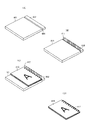
図5は、図4に示した穿孔装置222における、加工部412によってシートに対して施される加工処理を説明する図である。
図5において、加工部412には、ダイと呼ばれる穿孔器具501が交換可能な様式によって配置可能な構成を取っている。穿孔器具501は穿孔処理の型であり、穿孔器具501を交換することによって様々な穿孔処理が可能となっている。以下、加工部412によって為されるシートに対する穿孔等の加工処理の詳細を説明する。
穿孔器具501はパンチ部材の一例である。交換可能な穿孔器具501のそれぞれは、シートに穿孔する穴の形状、穴と穴との間隔、穴数、識別情報等の穿孔属性を備えている。ここで、パンチ部材は、製本装置223の綴じ部材417に整合している必要がある。本実施形態では製本装置223の綴じ部材417と、交換可能な穿孔器具501とが整合するかを判断することで、ミスマッチとなるようなシート後処理を回避する制御を行う。なお、当該制御の詳細は後述するフローチャートを用いて説明する。
<Explanation of drilling equipment>
FIG. 5 is a diagram illustrating a processing process applied to the sheet by the
In FIG. 5, the
The
加工対象シート505は穿孔処理の加工対象のシートであり、図4における搬送路405を経由し加工部412に導かれたシートを示している。穿孔部502は支柱503によって配置が強固に固定されているが、穿孔器具501の上方から圧力を加えることに依って穿孔部502が下方に押し出される。穿孔部502の先端は穿孔処理に好適なよう鋭利な穿孔形状を為しており、その結果、穿孔器具501の下方に配置されたシート505に対して穿孔処理が行われる。
The sheet to be machined 505 is a sheet to be machined for drilling, and shows a sheet guided to the machined
穿孔器具501は、穿孔属性により必要とする形状や穴数等に応じて各種用意されており、かつ柔軟に交換可能なよう構成される。例えば、2穴穿孔加工済みシート506に示すような、穴の形状は丸型で穴数が2つの成果物を得る場合には対応した形状の穿孔器具501を加工部412に配置する。一方、4穴穿孔加工済みシート507に示すように、穴の形状が四角、穴数が4である成果物を得る場合には同様に、対応した形状の穿孔器具501を加工部412に配置すればよい。
穿孔器具501が交換された場合、製本装置223は外部I/F202を通して、制御部205に穿孔器具501の変更を通知するか、交換後に操作者が操作部204を操作して手動で交換後の穿孔器具501の種類を入力する。
Various types of
When the
本実施形態における穿孔装置222は、穿孔器具501の上方から圧力を加えることによって、その下方に配置されたシートに加工を施すという装置の仕組みによって、穴あけ処理以外の加工処理も可能とする。具体的には、クリース加工済みシート508に示すようにシートの中央部にクリース509と呼ばれる折りを容易にするための筋を付けるための加工処理なども可能である。
The
製本処理を実現するための穿孔処理について、製本穿孔加工済みシート510によって示される図を用いて説明する。
図4において述べた通り、本実施形態における製本処理は製本装置233において、穿孔加工の為されたシートに綴じ部材417を貫通させる仕組みを前提としている。従って、穿孔装置222は、上述した穿孔属性である各種形状、穴数による穿孔処理を可能としているにも関わらず、当該製本処理時には、製本処理に好適な、すなわち、ダイと綴じ部材417とが整合する穿孔器具501によって穿孔加工がなされなければならない。
具体的には、シートに穿孔された穴の数が綴じ部材417と整合していなければならない。これは上述した通り、綴じ処理時において、綴じ部材417をシート510の穴部(シート穴)504に貫通させ、さらに綴じ部材417を変形させる処理を要することによる。
The perforation process for realizing the bookbinding process will be described with reference to the figure shown by the bookbinding perforated
As described in FIG. 4, the bookbinding process in the present embodiment is premised on a mechanism in which the binding
Specifically, the number of holes drilled in the sheet must match the binding
さらに、穴の間隔511と綴じ部材の間隔512が合致している必要があり、かつ穴のサイズ513よりも、綴じ部材417の貫通部のサイズ514が小さくなければ綴じ部材417を貫通させることができない。これらの条件も、上述した通り、製本処理の仕組みである、綴じ部材417をシート510の穴部504に貫通させ、変形させる処理を要することに由来するものである。
Further, the
このように製本処理を伴う穿孔処理では穿孔器具501が綴じ部材417と整合したものであることは印刷ジョブを完了させる上で必須である。
一方で、製本処理を伴わない通常の穿孔処理およびクリースのような処理の場合、穿孔処理に依存する後続の加工処理が存在しないため、必ずしも指定された穿孔処理に適した穿孔器具501が装着されていなくても印刷ジョブを完了させることは可能である。例えば、穿孔器具501がジョブで指定された穿孔処理の種類に一致しない場合、穿孔処理を行わずにトレイ228,229に排紙することが可能である。このように実行する印刷ジョブによっては、特定の製本処理が要求される場合には、上記ダイと綴じ部材417とが整合するように制御し、それ以外の場合は、印刷ジョブの処理を開始するように制御する。
As described above, in the perforation process involving the bookbinding process, it is essential that the
On the other hand, in the case of a normal drilling process and a crease-like process that does not involve a bookbinding process, there is no subsequent processing process that depends on the drilling process, so a
<とじ工程の説明>
図6は、図4に示した集積部415の近傍の構成を示す模式図であり、綴じ処理の仕組みの概要を説明するためのものである。
図6の(A)は処理開始前の集積部415の状態を表している。綴じ部材固定部601、602によって示される部材が並行して配置される。両部材の隙間603には、図4において説明した、所望の長さに切断された綴じ部材417が配置および固定されるための箇所である。
<Explanation of binding process>
FIG. 6 is a schematic view showing a configuration in the vicinity of the
FIG. 6A shows the state of the
図6の(B)に示す通り、綴じ部材417が集積部415に供給された後、綴じ部材417は綴じ部材固定部602、601によって所定の位置に正確に配置および固定される。次に、図6の(C)に示す通り、この状態に対して穿孔済みのシートが綴じ部材417に貫通する形で集積される。綴じ部材417は集積されるために搬送されたシートの穴の数や位置に対し、綴じ部材が貫通するよう正確に配置されるよう制御される。最終紙までの集積が完了したら、綴じ部材417を折り曲げ、変形させることによって図6の(D)に示すような製本成果物を得る。
As shown in FIG. 6B, after the binding
なお、集積部415を構成する部材、綴じ部材の形状は本実施形態による製本処理の仕組みを説明するために簡略化されたものであり、図6に示した形状に限定されるものではない。
例えば曲げ加工を容易とするために、図6に示すような直線的な綴じ部材ではなく、最初から湾曲形状をした綴じ部材を用いるなどの場合が考えられる。また、穴の数、間隔、形状等についても、各種存在しうるが、それらが如何なる態様のものであったとしても請求項記載の構成を満足する限り本発明は適用されることは言うまでもない。
The shapes of the members and the binding members constituting the
For example, in order to facilitate the bending process, it is conceivable to use a binding member having a curved shape from the beginning instead of the linear binding member as shown in FIG. Further, there may be various types of holes, such as the number, spacing, and shape, but it goes without saying that the present invention is applied to any form as long as the configuration described in the claims is satisfied.
<成果物の説明>
図7は、本実施形態を示すシート後処理装置による綴じ処理状態を示す図である。本例は、製本処理を実施した結果、得られる成果物の綴じ部材の形態例を断面的に示した例である。
図7の(A)に示す図は、シートの穿孔がある辺側から成果物を見た状態で、最初のシート701、2番目のシート702、それ以降のシート703という積載順によって集積部415に集積され、その状態で綴じ処理を施した状態を示している。シート束の穿孔部に貫通した綴じ部材417を折り曲げ、リング状にすることによってシートを束ねる方式である。従って、同図に示す通り、綴じ部材417の底部707と貫通部、すなわち上部708が交互に配置された形状として綴じ部材418を形成することになる。
<Explanation of deliverables>
FIG. 7 is a diagram showing a binding processing state by the sheet post-processing device showing the present embodiment. This example is an example in which a morphological example of the binding member of the product obtained as a result of performing the bookbinding process is shown in cross section.
In the figure shown in FIG. 7A, when the deliverable is viewed from the side where the sheet is perforated, the
しかしながら、リング状になった綴じ部材417の底部707と上部708が成果物の外側に露呈する様式の成果物は主に見た目における品位を著しく損なう。従って、図7の(B)で示される、綴じ処理実行後の成果物における最初のシート701を製本成果物の反対方向にめくった状態とすることによって、図7の(A)によって示したような、底部707と上部708が露呈した状態を解消し、見た目に好ましい品位の成果物を得ることが可能である。また、このような最初のシート701を反対方向にめくるという処理を想定し、成果物のシート積載順序が行われることを本実施形態における製本処理は前提としている。
However, the deliverable in a style in which the bottom 707 and top 708 of the ring-shaped binding
また、綴じ部材のサイズは予め定められたものが製本装置223に供給される一方で、製本成果物を構成するシートの枚数、もしくは束厚は印刷ジョブデータのページ数に応じて可変である。このようなことを想定し、様々な束厚の製本成果物を得るために、本実施形態における製本装置223は、サイズの異なる綴じ部材417を交換可能とする事により、異なる束厚の製本成果物であっても、適切に作成可能なよう構成されることを前提としている。
Further, while a predetermined size of the binding member is supplied to the
例えば、図7の(C)、図7の(D)に示す図は、サイズの異なる綴じ部材705、706を用いた場合の、製本成果物を綴じ部材417の長手方向から示したものであるが、同一束厚のシート束であっても、綴じ部材417のサイズが束厚を超えない限り、異なるサイズの綴じ部材417を利用した綴じ処理が可能である。しかしながら、束厚に適したサイズの綴じ部材417を使う方が成果物としては好ましい。もっともこれは当該MFP101を利用するユーザ、あるいは成果物の獲得者の主観に委ねられる。しかしながら、図7の(E)に示したように、束の厚みが、綴じ部材417が綴じることの出来るサイズを超えてしまった場合には前述したユーザあるいは成果物獲得者の主観に依らず、当該製本装置223における製本成果物作成処理は実行することが出来ない。この場合、ユーザは、束厚を小さくするか、若しくはより大きなサイズの綴じ部材417に換装し、処理を行う以外に正常な成果物を得る術はない。なお、綴じ部材417は積載されるシート上の穴704に向かって両側から折り曲げられるようにリング状のループを形成して綴じ込まれる。
For example, the figures shown in FIGS. 7 (C) and 7 (D) show the bookbinding product from the longitudinal direction of the binding
<操作部204に表示する画像の説明>
図8は、図2に示した操作部204に表示するUI画面(印刷設定画面)を示す図である。本例は、一連の製本設定画面である。
図8の(A)は製本設定画面800である。図8の(B)はパンチダイ不一致エラー画面820である。図8の(C)は用紙設定画面のうち用紙種類設定画面830である。図8の(D)は用紙設定画面のうち用紙サイズ設定画面840である。
<Explanation of the image displayed on the
FIG. 8 is a diagram showing a UI screen (print setting screen) displayed on the
FIG. 8A is a
前述の通り、操作者から操作部204への入力は制御部205へ伝送され、操作部204に表示する画面は制御部205からの指示によりに切り替えられる。以下では操作部204に表示する画面例と操作者の操作による操作部204の表示画面の遷移について説明する。
As described above, the input from the operator to the
操作者から製本設定画面の表示の指示を受け付けると、制御部205は操作部204に図8の(A)の製本設定画面800を表示する。製本設定画面800は、コピーの設定に関する画面の1つであり、製本面付けおよび仕上げを指定するための画面である。
Upon receiving an instruction to display the bookbinding setting screen from the operator, the
図8の(A)において、面付け指定ボタン801〜803は面付けの方法を指定するためのボタンである。選択された面付け指定ボタンは、他のボタンとは違う色で表示される。複数の面付け指定ボタンが同時に選択状態になることはなく、既に選択状態になっている面付け指定ボタンがある状態で、別の面付け指定ボタンを選択した場合、新たに選択した面付け指定ボタンが選択状態となり、先に選択状態となっていた面付け指定ボタンの選択状態が解除される。RAM208に選択状態が保存されている場合、その選択状態を初期状態とし、ない場合には製本面付けしないボタン803が選択された状態を初期状態とする。
In FIG. 8A, the imposition designation buttons 801 to 803 are buttons for designating the imposition method. The selected imposition specification button is displayed in a different color from the other buttons. If multiple imposition specification buttons are not selected at the same time and another imposition specification button is selected while there is an imposition specification button that is already selected, the newly selected imposition specification button is selected. The button becomes the selected state, and the selected state of the imposition designation button that was previously selected is canceled. If the selected state is saved in the
製本面付け指定ボタン801は面付け指定ボタンの1つであり、中とじ製本面付けを指定するためのボタンである。中とじ製本面付けでは画像の順番を入れ替え、1枚の用紙に2つの画像が印刷される。仕上げ処理で用紙の中央で二つ折りされることで冊子のような出力物を得ることができる。 The bookbinding imposition designation button 801 is one of the imposition designation buttons, and is a button for designating the saddle stitch bookbinding imposition. In saddle stitch binding imposition, the order of the images is changed, and two images are printed on one sheet of paper. A booklet-like output can be obtained by folding the paper in half in the finishing process.
ワイヤ製本面付け指定ボタン802は面付け指定ボタンの1つであり、ワイヤ製本面付けを指定するためのボタンである。図7を使用して説明したように、ワイヤ製本の成果物は、用紙の積載順序を変更する必要がある。具体的には裏表紙となる最後尾の用紙を最初に出力するように画像順序を入れ替えて積載順序を変更することが必要である。
ワイヤ製本面付け指定ボタン802を選択することで、この積載順序の変更に必要な処理が実施される。ワイヤ製本面付け指定ボタン802は、製本装置223がMFP101に接続されている場合のみ表示される。また、穿孔装置222に装着されている穿孔器具501が、ワイヤ綴じに適したものであるときのみ選択可能となる。
ワイヤ製本面付け指定ボタン802の表示・非表示、および選択の可不可の切り換えに関しては、図11を用いて詳細に説明する。
The wire binding
By selecting the wire binding
The display / non-display of the wire binding
製本面付けしない指定ボタン803は面付け指定ボタンの1つであり、製本面付けを行わないことを指定するためのボタンである。製本面付けを指定しない場合、用紙の1つの面に対し1つの画像が順番通りに印刷される。片面・両面の指定は不図示の通常面付け指定画面で設定可能である。 The binding designation button 803 for not imposing the bookbinding is one of the imposition designation buttons, and is a button for designating that the binding imposition is not performed. If binding imposition is not specified, one image is printed in order on one side of the paper. Single-sided / double-sided designation can be set on the normal imposition designation screen (not shown).
仕上げ指定ボタン804〜807は仕上げの方法を指定するためのボタンである。選択された面付け指定ボタンは、他のボタンとは違う色で表示される。複数の仕上げ指定ボタンが同時に選択状態になることはなく、既に選択状態になっている仕上げ指定ボタンがある状態で、別の仕上げ指定ボタンを選択した場合、新たに選択した仕上げ指定ボタンが選択状態となり、先に選択状態となっていた仕上げ指定ボタンの選択状態が解除される。RAM208に選択状態が保存されている場合その選択状態を初期状態とし、選択状態が保存されていない場合には仕上げなし指定ボタン807が選択された状態を初期状態とする。
Finishing specification buttons 804 to 807 are buttons for specifying the finishing method. The selected imposition specification button is displayed in a different color from the other buttons. If multiple finish specification buttons are not selected at the same time and there is a finish specification button that is already selected and another finish specification button is selected, the newly selected finish specification button is selected. Then, the selected state of the finish specification button that was previously selected is canceled. If the selected state is saved in the
折り+中とじ指定ボタン804は仕上げ指定ボタンの1つであり、用紙を中央で折る処理とステイプルでとじる処理を指定するためのボタンである。製本面付け指定ボタン801と合わせて指定をすることで、中とじされた冊子状の成果物を得ることができる。 The fold + saddle stitch designation button 804 is one of the finish designation buttons, and is a button for designating the process of folding the paper in the center and the process of binding with staples. By designating in combination with the bookbinding imposition designation button 801, a saddle-stitched booklet-shaped deliverable can be obtained.
折り指定ボタン805は仕上げ指定ボタンの1つであり、用紙の中央で折る処理を指定するためのボタンである。製本面付け指定ボタン801と合わせて指定をすることで、冊子状の成果物を得ることができる。
The
ワイヤ綴じ指定ボタン806は仕上げ指定ボタンの1つであり、ワイヤを使用したとじを指定するためのボタンである。ワイヤ綴じ指定ボタン806とワイヤ製本面付け指定ボタン802とが合わせて指定されることで、ワイヤでとじられて製本処理された出力物を得ることができる。ワイヤ綴じ指定ボタン806は、ワイヤ製本面付け指定ボタン802と同様、製本装置223がMFP101に接続されている場合のみ表示される。また、穿孔装置222に装着されている穿孔器具501が、ワイヤ綴じに適したものであるときのみ選択可能となる。図11を用いて詳細に説明する。
The wire
仕上げなし指定ボタン807は仕上げ指定ボタンの1つであり、仕上げを行わないことを指定するためのボタンである。仕上げを行わない場合、製本に関わる仕上げ処理は行われない。
The
表紙指定ボタン808は、製本成果物に表紙を付けることを指定するためのボタンである。表紙指定ボタン808が選択されると制御部205は、面付け指定ボタン801〜803と仕上げ指定ボタン804〜807の選択状態をRAM208に一時的に保存し、不図示の表紙設定画面を表示する。
表紙設定画面では表紙に使用する用紙の種類や印刷面を指定することが可能である。表紙設定画面が終了したら、制御部205はRAM208に保存したボタンの選択状態を読み出し、読み出した選択状態を初期状態とした上で操作部204に製本設定画面800を表示する。
The cover page designation button 808 is a button for designating that a cover page is attached to the bookbinding product. When the cover page designation button 808 is selected, the
On the cover setting screen, it is possible to specify the type of paper used for the cover and the printing surface. When the cover setting screen is finished, the
開き方指定ボタン809は製本成果物の開き方向(右開き、左開きなど)を指定するためのボタンである。開き方指定ボタン809が選択されると制御部205は、面付け指定ボタン801〜803と仕上げ指定ボタン804〜807の選択状態をRAM208に一時的に保存し、不図示の開き方設定画面を表示する。開き方設定画面では製本の開き方向を指定することが可能である。開き方設定画面が終了したら、制御部205はRAM208に保存したボタンの選択状態を読みだし、読みだした選択状態を初期状態とした上で操作部204に製本設定画面800を表示する。
The opening method specification button 809 is a button for specifying the opening direction (right opening, left opening, etc.) of the binding product. When the opening method specification button 809 is selected, the
用紙設定ボタン810は、使用する用紙を指定するためのボタンである。用紙設定ボタン810が選択されると制御部205は、面付け指定ボタン801〜803と仕上げ指定ボタン804〜807の選択状態をRAM208に一時的に保存し、用紙設定画面830、840を表示する。用紙設定画面830、840に関しては図8の(C)、(D)を用いて説明をする。
用紙設定画面830、840が終了したら、制御部205はRAM208に保存したボタンの選択状態を読み出し、読み出した選択状態を初期状態とした上で操作部204に製本設定画面800を表示する。
The paper setting button 810 is a button for specifying the paper to be used. When the paper setting button 810 is selected, the
When the paper setting screens 830 and 840 are completed, the
設定取消ボタン811は、製本設定を確定させずに終了するためのボタンである。設定取消ボタン811の選択を受付けた場合は、製本設定画面800で行われた面付け方法、仕上げ方法、および表紙設定画面で行われた表紙設定、開き方設定画面で行われた開き方向の指定、用紙設定画面830、840で行われた用紙設定を保存することなく破棄し、遷移元の画面に遷移する。
The setting cancel button 811 is a button for terminating the bookbinding setting without confirming it. When the selection of the setting cancel button 811 is accepted, the imposition method and finishing method performed on the
OKボタン812は、製本設定を終了するためのボタンである。OKボタン812への指示を受け付けた場合には、製本設定画面800で行われた面付け方法、仕上げ方法、および表紙設定画面で行われた表紙設定、開き方設定画面で行われた開き方向、用紙設定画面830、840で行われた用紙設定を印刷ジョブで使用する設定としてRAM208に保存し、遷移元の画面に遷移する。
The
表紙指定ボタン808、開き方指定ボタン809、用紙設定ボタン810、設定取消ボタン811、OKボタン812のいずれのボタンも指示されることなく、製本設定画面800から遷移した場合、製本設定画面800で行われた面付け方法、仕上げ方法、および表紙設定画面で行われた表紙設定、開き方設定画面で行われた開き方向の指定を破棄する。ただしスクリーンセイバなどの一時的かつ、解除後に製本設定画面800に戻る画面遷移に関しては一時的に保存された設定を破棄しない。
If you transition from the
後述するプリント処理において、ワイヤ綴じに適切な穿孔器具が穿孔装置222に装着されていない状態で、ワイヤ綴じ指定が設定された印刷ジョブの処理順番となると、操作部204に図8の(B)のパンチダイ不一致エラー画面820が表示される。パンチダイ不一致エラー画面820は、操作者にワイヤ綴じに適切な穿孔器具501が装着されていないことを通知し、交換を促すための画面である。適切な穿孔器具501に交換されるまで印刷ジョブは中断状態となる。
In the printing process described later, when the processing order of the print job for which the wire binding designation is set is reached in a state where the punching device suitable for wire binding is not attached to the
要求パンチダイ表示821は必要な穿孔器具を表示するための領域である。該領域には、ワイヤ綴じを実施するために必要な穿孔器具を特定する識別情報が表示される。識別情報は穿孔器具の商品名、商品番号の他、操作者が任意に定めた管理番号や管理名でもかまわない。
The required punch die
パンチダイ交換手順表示822は穿孔器具501を交換するのに必要な手順を説明するための表示領域である。該表示領域には、穿孔器具の場所を示す画像のほか、アニメーションを使用して交換手順が表示される構成でもよい。
The punch die
装着パンチダイ表示823は現在装着されている穿孔器具501を表示するための領域である。該領域には、現在装着されている穿孔器具501を特定することのできる識別情報が表示される。識別情報は要求パンチダイ表示821に表示するものと同等のものである。
The mounting
中止ボタン824は、印刷ジョブを中止するためのボタンである。中止ボタン824の選択が受けつけられると、受け付けた印刷ジョブが中止される。HDD209に保存した印刷ジョブに関する設定情報およびに画像データは破棄される。また操作部204でのパンチダイ不一致エラー画面820の表示は終了し、遷移元の画面に遷移する。
The stop button 824 is a button for stopping the print job. When the selection of the stop button 824 is accepted, the accepted print job is canceled. The setting information and image data related to the print job saved in
閉じるボタン825は、パンチダイ不一致エラー画面を終了するためのボタンである。閉じるボタンの選択が受け付けられると、操作部204でのパンチダイ不一致エラー画面820の表示は終了し、遷移元の画面に遷移する。この場合、適切な穿孔器具501は装着されていないため印刷ジョブは再開されずに中断状態のままとなる。
The
製本設定画面800において、操作者から用紙設定ボタン810が選択されると、制御部205は操作部204に図8の(C)の用紙種類設定画面830を表示する。用紙種類設定画面830は、用紙設定画面のうちの1つであり、製本が指定される印刷ジョブにおいて使用する用紙の種類を設定するための画面である。ここでは用紙設定画面を用紙種類設定画面830と図8の(D)の用紙サイズ設定画面840の2つにわけ、用紙種類設定画面830を先に表示するようにしているが、同一の画面で両方の設定ができるようにしてもよく、表示順番も逆でも構わない。
When the paper setting button 810 is selected by the operator on the
用紙の種類設定ボタン831〜837は、印刷ジョブで使用する用紙の種類を設定する画面である。選択された用紙の種類設定ボタンは、他のボタンとは違う色で表示される。複数の用紙の種類設定ボタンが同時に選択状態になることはなく、既に選択状態になっている用紙の種類設定ボタンがある状態で、別の用紙の種類設定ボタンが選択された場合、新たに選択された用紙の種類設定ボタンが選択状態となり、先に選択状態となっていた用紙の種類設定ボタンの選択状態が解除される。RAM208に選択状態が保存されている場合その選択状態を初期状態とし、選択状態が保存されていない場合には普通紙ボタン832が選択された状態を初期状態とする。
The paper type setting buttons 831 to 837 are screens for setting the type of paper used in the print job. The selected paper type setting button is displayed in a different color from the other buttons. Multiple paper type setting buttons are not selected at the same time, and if there is a paper type setting button that is already selected and another paper type setting button is selected, a new selection is made. The selected paper type setting button is selected, and the previously selected paper type setting button is released. If the selected state is saved in the
設定取消ボタン838は、用紙の種類設定を終了するためのボタンである。設定取消ボタン838の選択が受けつけられると、用紙種類設定画面830、用紙サイズ設定画面840で行われた用紙設定は保存されることなく破棄され、製本設定画面800に遷移する。
The setting cancel button 838 is a button for ending the paper type setting. When the selection of the setting cancel button 838 is accepted, the paper settings made on the paper
次へボタン839は、用紙の種類設定を終了するためのボタンである。次へボタン839の選択が受け付けられると、用紙の種類設定ボタン831〜837の選択状態がRAM208に一時的に保存され、用紙サイズ設定画面840に遷移する。
用紙種類設定画面830において、操作者から次へボタン839が選択されると、制御部205は操作部204に図8の(D)の用紙サイズ設定画面840を表示する。用紙サイズ設定画面840は、印刷ジョブにおいて使用する用紙のサイズを設定する画面である。
When the
用紙サイズ設定ボタン841〜849は、印刷ジョブで使用する用紙のサイズを設定するためのボタンである。選択された用紙サイズ設定ボタンは、他のボタンとは違う色で表示される。複数の用紙サイズ設定ボタンが同時に選択状態になることはなく、既に選択状態になっている用紙サイズ設定ボタンがある状態で、別の用紙サイズ設定ボタンが選択された場合、新たに選択された用紙サイズ設定ボタンが選択状態となり、先に選択状態となっていた用紙サイズ設定ボタンの選択状態が解除される。RAM208に選択状態が保存されている場合その選択状態を初期状態とし、選択状態が保存されていない場合にはA4ボタン841が選択された状態を初期状態とする。
Paper
設定取消ボタン850は、用紙サイズ設定を終了するためのボタンである。設定取消ボタン850の選択が受けつけられると、用紙種類設定画面830、用紙サイズ設定画面840で行われた用紙設定が保存されることなく破棄され、製本設定画面800に遷移する。
The setting cancel
OKボタン851は、用紙サイズ設定を終了するためのボタンである。OKボタン851の選択が受け付けられると、用紙種類設定画面830、用紙サイズ設定画面840で行われた用紙の種類および用紙サイズが印刷ジョブで使用する用紙としてRAM208に保存される。
The OK button 851 is a button for finishing the paper size setting. When the selection of the OK button 851 is accepted, the paper type and paper size performed on the paper
<MFP起動時のフローチャート>
図9は、本実施形態を示す画像形成装置の制御方法を説明するフローチャートである。本例は、図1に示したMFP起動時の処理において、特に本実施系に関連する部分の制御部205の処理手順に対応する。なお、各ステップは、制御部205が備えるCPUが記憶された制御プログラムを実行することで実現される。
S901で、制御部205はMFP起動処理を行う。この処理は通常のMFP起動時の処理と同等であるため詳細は省略する。MFP起動処理が終了したら、制御部205は、処理をS902に進める。
S902で、制御部205は穿孔装置222の装着の有無を取得し、RAM208に記憶する。装着の有無は外部I/F202を介して穿孔装置222と通信を行うことで取得される。すなわち通信が確立されている状態では、穿孔装置222が装着されていることになる。制御部205は、穿孔装置222の有無をRAM208に記憶したら、制御部205は、処理をS903に進める。
<Flowchart when starting the MFP>
FIG. 9 is a flowchart illustrating a control method of the image forming apparatus showing the present embodiment. This example corresponds to the processing procedure of the
In S901, the
In S902, the
S903で、制御部205はS902での取得結果に基づいて穿孔装置222が装着されているかを判断する。穿孔装置222が装着されていると制御部205が判断した場合、制御部205は、処理をS904に進め、装着されていないと制御部205が判断した場合、制御部205は、処理をS906へ進める。
In S903, the
S904で、制御部205は外部I/F部202を介して穿孔装置222と通信し、穿孔装置222に装着されている穿孔器具の種類の情報を取得し、RAM208に記憶する。取得する情報は穿孔器具の種類を識別することの出来る識別情報であり、穿孔器具501の名称や商品番号、登録番号、穿孔部502の数などである。制御部205は取得した情報から特定される穿孔器具501の種類をRAM208に記憶したら、制御部205は、処理をS905に進める。
In S904, the
S905で、制御部205はMFP101への製本装置223の装着の有無を取得し、RAM208に記憶する。装着の有無は外部I/F202を介して穿孔装置222と通信を行うか、直接製本装置223と通信を行うことで取得される。制御部205は製本装置223の有無をRAM208に記憶したら、制御部205はMFP起動時の処理を終了する。
In S905, the
<待機状態のフローチャート>
図10は、本実施形態を示す画像形成装置の制御方法を説明するフローチャートである。本例は、待機状態から印刷ジョブの製本設定または印刷ジョブの受け付けを行う時の制御部205の制御手順に対応する。なお、各ステップは、制御部205が備えるCPUが記憶された制御プログラムを実行することで実現される。
<Flowchart in standby state>
FIG. 10 is a flowchart illustrating a control method of the image forming apparatus showing the present embodiment. This example corresponds to the control procedure of the
S1001では、制御部205は操作者からの入力および接続機器からの通信を待機する。操作者から入力を受け付けた、または接続機器から通信を受けつけた場合、制御部205は、処理をS1002に進める。一方、入力、通信がないと制御部205が判断した場合、制御部205はS1001で次の処理を待機する。
S1002では、制御部205はS1001で受け付けた接続機器からの通信が、外部I/F202を介した印刷ジョブの受け付けであるか否かを判断する。ここで、印刷ジョブを受け付けたと制御部205が判断した場合には、制御部205は、処理をS1003に進め、印刷ジョブを受け付けていないと制御部205が判断した場合には、制御部205は、処理をS1005に進める。
In S1001, the
In S1002, the
S1003では、制御部205はS1001で受け付けた印刷ジョブを解析し、ワイヤ綴じが指定されているかを判断する。ここで、ワイヤ綴じが指定されていると制御部205が判断した場合には、制御部205は、処理をS1004に進め、指定されていないと制御部205が判断した場合には、制御部205は、処理をS1007に進める。
なお、このステップは図11を用いて後述する印刷ジョブ処理開始時の処理の中で行っても構わない。その場合、制御部205は、S1003,S1004を実行せず、処理をS1002からS1007に進める。
In S1003, the
Note that this step may be performed in the process at the start of the print job process, which will be described later with reference to FIG. In that case, the
S1004では、制御部205はS905でRAM208に記憶した製本装置223の有無を参照し、製本装置223が装着されているかを判断する。ここで、製本装置223が装着されていると制御部205が判断した場合、制御部205は、処理をS1007に進め、製本装置223が装着されていないと制御部205が判断した場合、制御部205は、処理をS1006に進む。
In the S1004, the
S1006では、制御部205は受け付けた印刷ジョブを中止する。具体的には、制御部205はHDD209に保存した印刷ジョブに関する設定情報および画像データを削除して、中止処理を確定する。その後、制御部205は、処理をS1001に戻す。
S1007では、制御部205は、受け付けた印刷ジョブを保留とするためRAM208に確保されるジョブキューに格納し、その後、制御部205は、処理をS1001に戻す。
In S1006, the
In S1007, the
一方、S1005では、制御部205がS1001で受け付けた操作者からの入力および接続機器からの通信が、外部I/F202を介した穿孔装置222からの穿孔器具501の変更通知、または操作者が操作部204を操作して交換後の穿孔器具205の種類を入力する操作であるかを判断する。ここで、穿孔器具501の変更通知を受け付けたと制御部205が判断した場合、制御部205は、処理をS1008に進め、穿孔器具501の変更通知を受け付けていないと制御部205が判断した場合は、制御部205は、処理をS1009に進める。
On the other hand, in S1005, the input from the operator and the communication from the connected device received by the
S1008では、制御部205は装着された穿孔器具501を特定する情報(識別情報)を取得し、RAM208に記憶する。すでにRAM208に穿孔器具501を特定する情報が記憶されていると制御部205が判断した場合、取得した情報で既に取得した穿孔器具501の情報を更新する。
なお、S1005で受信した情報の中に、製本装置223に装着された穿孔器具501の種類に関する情報が含まれていてもよい。
また、制御部205は、S1005における通信とは別の通信で、穿孔装置222から穿孔器具501の種類の情報を取得する通信を行っても良い。このようにして、制御部205は、穿孔器具501の種類をRAM208に記憶したら、制御部205は、処理をS1001に進める。
In the S1008, the
The information received by the S1005 may include information regarding the type of
Further, the
次に、S1009で、制御部205はS1001で受け付けた操作者からの入力が製本設定画面を表示する指示であったかを判断する。ここで、製本設定画面を表示する指示であると制御部205が判断した場合には、制御部205は、処理をS1010に進め、製本設定画面を表示する指示でないと制御部205が判断した場合には、制御部205は、処理をS1001に進める。
次に、S1010で、制御部205は操作部204の表示部に製本画面を表示する処理を行う。なお、製本画面を表示する処理については図11を用いて説明する。このようして、当該製本画面表示処理が終了したら、制御部205は、処理をS1001に戻す。
Next, in S1009, the
Next, in S1010, the
<ワイヤ製本設定画面表示処理のフローチャート>
図11は、本実施形態を示す画像形成装置の制御方法を説明するフローチャートである。本例は、製本設定画面を表示する指示を受け付けた時の制御部205の処理手順に対応する。なお、各ステップは、制御部205が備えるCPUが記憶された制御プログラムを実行することで実現される。以下、制御部205が第1の装置に装着されているパンチ部材が第2の装置である製本装置223が使用する綴じ部材417に対応していないと判断した場合、印刷設定画面において、製本装置223を使用する製本設定を選択できないように制御する例を説明する。なお、制御部205は、装着されたパンチ部材の仕様と、製本装置223が使用する綴じ部材の仕様とを比較する。これにより、第1の装置に装着されているパンチ部材が第2の装置である製本装置223が使用する綴じ部材417に対応しているか否かを判断する。より具体的には、制御部205が綴じ部材の凸部のサイズと、穿孔された穴のサイズ等や、穿孔される穴に隣接して穿孔される穴との間隔と、綴じ部材の凸部の間隔が一致しているかを製本装置223や穿孔装置222から取得する情報から判断する。
<Flowchart of wire binding setting screen display processing>
FIG. 11 is a flowchart illustrating a control method of the image forming apparatus showing the present embodiment. This example corresponds to the processing procedure of the
S1101で、制御部205は、S905でRAM208に記憶した製本装置223の有無を示す情報を参照し、製本装置223が装着されているかを判断する。ここで、製本装置223が装着されていると制御部205が判断した場合、制御部205は、処理をS1102に進め、製本装置223が装着されていないと制御部205が判断した場合、制御部205は、処理をS1105に進める。
S1102で、制御部205はS904またはS1008でRAM208に記憶した穿孔器具501の種類の情報を参照し、装着されている穿孔器具501がワイヤ綴じに適したものであるかを判断する。ここで、ワイヤ綴じに適した穿孔器具501が装着されていると制御部205が判断した場合、制御部205は、処理をS1104に進め、ワイヤ綴じに適した穿孔器具501が装着されていないと制御部205が判断した場合には、制御部205は、処理をS1103に進める。ここで、ワイヤ綴じに適した穿孔器具501が装着されている状態とは、穿孔器具501で穿孔される穴のサイズ、位置、穴の数等が製本装置223のワイヤ綴じ構成と一致する状態をいう。
In S1101, the
In S1102, the
S1103では、制御部205は操作部204の表示部に表示する製本設定画面800のワイヤ製本面付け指定ボタン802およびワイヤ綴じ指定ボタン806を選択不可能とすることを決定する。ここで、選択不可能な状態とは、制御部205が操作部204の表示部にボタンは表示するが、グレーアウトするなどの区別する表示制御を行うことにより、ユーザがワイヤ綴じ指定を選択できない状態である。
制御部205は、S1103により、製本設定画面800のワイヤ製本面付け指定ボタン802およびワイヤ綴じ指定ボタン806を選択不可能とすることを決定する処理が完了したら、制御部205は、処理をS1106に進める。
一方、S1104では、制御部205は、製本設定画面800においてワイヤ製本面付け指定ボタン802およびワイヤ綴じ指定ボタン806を選択可能とすることを決定する。その後、制御部205は、処理をS1106に進める。
S1105では、制御部205は、ワイヤ製本面付け指定ボタン802およびワイヤ綴じ指定ボタン806を非表示とすることを決定したら、制御部205は、処理をS1106に進める。
In S1103, the
When the
On the other hand, in S1104, the
In S1105, when the
S1106で、制御部205は操作部204の表示部に製本設定画面800を表示する。製本設定画面800に関しては図8の(A)を用いて説明した。制御部205は、操作部204に製本設定画面を表示したら、製本設定画面表示処理のフローを終了する。
In S1106, the
<印刷ジョブ処理開始時のフローチャート>
図12は、本実施形態を示す画像形成装置の制御方法を説明するフローチャートである。本例は、印刷ジョブの処理を開始する時の制御部205の制御手順に対応する。なお、各ステップは、制御部205が備えるCPUが記憶された制御プログラムを実行することで実現される。また、本処理において、制御部205はRAM208に確保される印刷ジョブキューを監視しており、印刷ジョブキューに印刷ジョブが格納された場合に、先頭の印刷ジョブに対して処理を開始する。
以下、印刷ジョブにワイヤ綴じ製本処理が指定されている場合に、ワイヤ綴じ処理と、シートを穿孔するパンチ処理とが整合しない場合に、印刷ジョブの実行を禁止し、禁止した印刷ジョブを続行する場合と、印刷ジョブの実行を中止する場合とを分けて説明する。
<Flowchart at the start of print job processing>
FIG. 12 is a flowchart illustrating a control method of the image forming apparatus showing the present embodiment. This example corresponds to the control procedure of the
Hereinafter, when the wire binding process is specified for the print job and the wire binding process and the punch process for punching the sheet do not match, the execution of the print job is prohibited and the prohibited print job is continued. The case and the case where the execution of the print job is stopped will be described separately.
S1201で、制御部205はネットワークを介して受信したHDD209に保存されている印刷ジョブの設定を参照し、ワイヤ綴じが指定されているかを判断する。ここで、制御部205は、ワイヤ綴じが指定されていると判断した場合には、制御部205は、処理をS1203に進め、ワイヤ綴じが指定されていないと判断した場合には、制御部205は、処理をS1202に進める。
In S1201, the
S1202で、制御部205はHDD209に保存されている印刷ジョブの設定を参照し、穿孔装置222を使用した加工処理が指定されているかを判断する。図5を使用して説明したように、加工処理には穿孔処理のほかクリースのような処理が含まれる。ここで、制御部205は、穿孔装置222を使用した加工処理が指定されていると判断した場合には、制御部205は、処理をS1205に進め、指定されていないと判断した場合には、制御部205は、処理をS1209に進める。
S1205で、制御部205はS904またはS1008でRAM208に記憶した穿孔器具501の種類の情報を参照し、装着されている穿孔器具501が指定された加工処理に適したものであるか判断する。ここで、制御部205は、装着されている穿孔器具501が指定された加工処理に適したものであると判断した場合には、制御部205は、処理をS1209に進める。一方、S1205で、制御部205は、指定された加工処理に適した穿孔器具501が装着されていないと判断した場合には、制御部205は、処理をS1207に進める。
In S1202, the
In S1205, the
S1207で、制御部205は印刷ジョブの設定を変更し、加工処理を無効とする。すなわち、穿孔装置を使用した加工処理を行わないように印刷ジョブを変更する。制御部205は、変更後の印刷ジョブをHDD209に保存する。なお、変更された印刷ジョブをHDD209に格納することで、当該印刷ジョブの変更を永続的なものとしてもよい。あるいは、制御部205が変更された印刷ジョブをRAM208に保持することで一時的な変更としてもよい。このように制御部205は、印刷ジョブの変更を終了したら、制御部205は、処理をS1209に進める。
In S1207, the
一方、S1203で、制御部205はS904またはS1008でRAM208に記憶した穿孔器具501の種類の情報を参照し、装着されている穿孔器具501がワイヤ綴じに適したものであるかを判断する。ここで、制御部205は、ワイヤ綴じに適した穿孔器具501が装着されていると判断した場合には、制御部205は、処理をS1209に進める。一方、S1203で、制御部205は、ワイヤ綴じに適した穿孔器具501が装着されていないと判断した場合には、制御部205は、処理をS1204に進める。
On the other hand, in S1203, the
S1204で、制御部205は操作部204に図8の(B)に示したパンチとダイとが不一致の状態を示すパンチダイ不一致エラー画面820を表示する。制御部205は不一致エラー画面820を表示したら、処理をS1206に進める。次に、S1206で、制御部205は、操作者からの入力および接続機器からの通信を待機する。ここで、制御部205は、操作者から入力を受け付けた、または接続機器から通信を受け付けた場合、制御部205は、処理をS1208に進める。一方、S1206で、制御部205は、入力、通信がないと判断した場合、制御部205は、再びS1206を実行する。
In S1204, the
ここで、ユーザは、外部I/F202を介した穿孔装置222からの穿孔器具501の変更通知または操作者が操作部204を操作して交換後の穿孔器具205の種類を入力する操作を行う。
S1208では、制御部205は、S1206で操作者が操作部204を操作して入力された交換後の穿孔器具205の種類と、RAM208に記憶した穿孔器具501の種類の情報を参照し、ワイヤ綴じに適した穿孔器具501が装着されたかを判断する。ここで、制御部205は、ワイヤ綴じに適した穿孔器具501が装着されたと判断した場合、制御部205は、処理をS1209に進める。
一方、制御部205は、S1206で受け付ける通知が、外部I/F202を介した穿孔装置222からの穿孔器具501の変更通知でないと判断した場合、またはワイヤ綴じに適した穿孔器具501が装着されていないと判断した場合には、制御部205は、処理をS1210に進める。
S1210で、制御部205はS1206で受け付けた操作者からの入力が印刷ジョブを中止する指示であったかを判断する。ここで、制御部205は、印刷ジョブの中止を受け付けたと判断した場合、制御部205は、処理をS1211へ進める。一方、制御部205は、S1206で受け付けた操作者からの入力が印刷ジョブを中止する指示を受け付けていないと判断した場合には、制御部205は、処理をS1206に戻す。
S1211では、制御部205は、S1206で受け付けた操作者からの入力が印刷ジョブを中止する指示に従い印刷ジョブを中止する。具体的には、制御部205はHDD209に保存した印刷ジョブに関する設定情報および画像データを削除し、印刷ジョブキューから除去する。そして、制御部205が、S1206で受け付けた操作者からの入力が印刷ジョブを中止する指示に従い印刷ジョブを中止したら、制御部205は、印刷ジョブ処理開始時のフローを終了する。
Here, the user performs a change notification of the
In S1208, the
On the other hand, when the
In S1210, the
In S1211, the
S1209で、制御部205は印刷ジョブの印刷処理を行う。この処理は通常の印刷処理と同様である。
なお、S1201でワイヤ綴じが指定されていると判断される印刷ジョブには、印刷処理に図5で説明した穿孔工程、図6で説明した綴じ工程が含まれる。印刷処理が終了したら印刷ジョブキューから印刷ジョブが除去され、印刷ジョブ処理開始時のフローは終了する。
以上により、操作者は装着されている穿孔器具の種類を印刷ジョブが入力する前に認識しておく必要がなく、不適な穿孔器具が装着されている場合には処理が中断される。
また、印刷ジョブを開始する前に、操作者に穿孔するダイ(現在セットされているダイ)と、製本する際に使用する綴じ部材とが整合していないことが通知される。このため、操作者は、通知される指示に従って、穿孔器具を交換するなどして適切に対応することで、所望するシート後処理が実行された成果物を得ることが可能となる。
In S1209, the
The print job determined to specify wire binding in S1201 includes the punching process described with reference to FIG. 5 and the binding process described with reference to FIG. 6 in the printing process. When the print process is completed, the print job is removed from the print job queue, and the flow at the start of the print job process ends.
As described above, the operator does not need to recognize the type of the drilling device installed before the print job inputs, and the process is interrupted when an inappropriate drilling device is installed.
Further, before starting the print job, the operator is notified that the die to be drilled (the die currently set) and the binding member used for binding are not aligned. Therefore, the operator can obtain a product in which the desired sheet post-processing has been performed by taking appropriate measures such as exchanging the drilling device according to the notified instruction.
本実施形態で実現される画像形成装置では、適切な穿孔器具が装着されているかを判断し、装着されていない場合には、操作部を介して操作者が印刷ジョブでワイヤ綴じを指定できないようにすることができる。
また、適切な穿孔器具が装着されていない状態で、画像形成装置がワイヤ綴じが指定された印刷ジョブを受け付けた場合、印刷ジョブの処理開始時にエラーが操作部に表示され、印刷ジョブの処理が中断される。
これにより、操作者が意図しない成果物を作成したり、綴じ部材や用紙、トナーといった消耗品を浪費したりすることを防ぐことができる。
In the image forming apparatus realized in the present embodiment, it is determined whether or not an appropriate drilling device is attached, and if it is not attached, the operator cannot specify wire binding in the print job via the operation unit. Can be.
In addition, if the image forming apparatus accepts a print job for which wire binding is specified without an appropriate drilling tool attached, an error is displayed on the operation unit at the start of the print job processing, and the print job processing is performed. It will be interrupted.
This makes it possible to prevent the operator from creating unintended deliverables and wasting consumables such as binding members, paper, and toner.
〔第2実施形態〕
上記第1実施形態では、製本装置203と穿孔器具501を考慮して印刷ジョブのワイヤ綴じ指定の可否、印刷ジョブの処理開始の可否を決定する場合について説明した。
しかし、用紙のサイズにより適した穿孔器具501や穿孔部502が異なっている場合や、穿孔工程を必要としない用紙の種類も存在する。
そこで、第2実施形態では上記事項にも適応する実施形態について記載する。なお、MFP起動時の処理の流れは図9と同じであり、待機状態の処理の流れは図10と同じである。
[Second Embodiment]
In the first embodiment, the case of determining whether or not the wire binding of the print job can be specified and whether or not the process of the print job can be started is described in consideration of the
However, there are cases where the
Therefore, in the second embodiment, an embodiment that also applies to the above items will be described. The processing flow at the time of starting the MFP is the same as that in FIG. 9, and the processing flow in the standby state is the same as that in FIG.
<製本設定画面表示処理のフローチャート>
図13は、本実施形態を示す画像形成装置の制御方法を説明するフローチャートである。本例は、製本設定画面表示の制御部205の処理手順に対応する。なお、各ステップは、制御部205が備えるCPUが記憶された制御プログラムを実行することで実現される。また、第1実施形態と共通の処理に関しては省略して説明をする。
S1301の処理は、S1101と同じである。S1302で、制御部205は印刷ジョブで使用する用紙としてRAM208に保存されている用紙設定を取得する。用紙設定には用紙の種類と用紙のサイズが含まれる。用紙設定に関しては図8の(C)、(D)を用いて説明を行った。制御部205は、用紙設定を取得したら、制御部205は、処理をS1303に進める。
<Flowchart of bookbinding setting screen display processing>
FIG. 13 is a flowchart illustrating a control method of the image forming apparatus showing the present embodiment. This example corresponds to the processing procedure of the
The processing of S1301 is the same as that of S1101. In S1302, the
S1303で、制御部205は取得した用紙設定の用紙サイズがワイヤ綴じを実施可能な用紙サイズであるかを判断する。ここで、制御部205は、取得した用紙サイズがワイヤ綴じを実施可能な用紙サイズであると判断した場合、制御部205は、処理をS1304に進める。一方、制御部205は、取得した用紙サイズがワイヤ綴じを実施可能でない用紙サイズであると判断した場合には、制御部205は、処理をS1307に進める。
S1304で、制御部205は取得した用紙設定の用紙種類がパンチ済み紙であるかを判断する。ここで、制御部205は、用紙種類がパンチ済み紙であると判断した場合には、制御部205は、処理をS1308に進める。一方、制御部205は、用紙種類がパンチ済み紙でないと判断した場合には、制御部205は、処理をS1305に進める。なお、S1305の処理は、図11に示したS1102と同じである。
In S1303, the
In S1304, the
S1306で、制御部205は取得した用紙設定の用紙サイズとRAM208に記憶した穿孔器具501の種類を比較し、穿孔部502で穿孔する穴の数が用紙サイズに適したものであるかを比較判断する。これは例えば、A4の用紙にワイヤ綴じを行う場合34個の穴が必要であり、LTRの場合は32個の穴が必要である。このため、制御部205はS1306で、用紙サイズの違いによる穴の必要数と穿孔部502で穿孔する穴数とを比較する。
なお、穿孔器具501の種類で一意に穿孔部の穿孔数が決まるのであれば、制御部205は、S1306における比較を穿孔器具501の種類で行ってもよく、そうでなければ穿孔装置222との通信や操作者からの入力により穿孔部502の数を直接取得して行っても良い。制御部205は、当該S1306における比較を行った結果、用紙サイズと穿孔部502の穿孔数が一致していると判断した場合、制御部205は、処理をS1308に進める。一方、制御部205は、S1306で用紙サイズと穿孔部502の数が一致していないと判断した場合、制御部205は、処理をS1307に進める。なお、S1307〜S1309の処理は、S1103〜S1105と同じである。
In S1306, the
If the number of perforations to be perforated is uniquely determined by the type of
S1310で、制御部205は操作部204に製本設定画面800を表示する。この時、既にS1307が実行されていれば、RAM208に一時的に保存されている面付け指定ボタン801〜803と仕上げ指定ボタン804〜807の選択状態がワイヤ製本面付け指定ボタン802、ワイヤ綴じ指定ボタン806であっても、制御部205はこれらの設定を破棄する。その際、制御部205は、製本面付けしないボタン803、仕上げなしボタン807が選択された状態を初期状態とするように操作部の画面表示を制御する。
In S1310, the
<印刷ジョブ処理開始時のフローチャート>
図14は、本実施形態を示す画像形成装置の制御方法を説明するフローチャートである。本例は、印刷ジョブの処理を開始する時の制御部205の制御手順に対応する。なお、各ステップは、制御部205が備えるCPUが記憶された制御プログラムを実行することで実現される。なお、第1実施形態と共通の処理に関しては省略する。S1401はS1201と同じである。
S1402で、制御部205はHDD209に格納されている印刷ジョブの設定を参照し、用紙設定の用紙サイズがワイヤ綴じを実施可能な用紙サイズであるかを判断する。ここで、制御部205は、用紙サイズがワイヤ綴じを実施可能な用紙サイズであると判断した場合、制御部205は、処理をS1403に進める。一方、制御部205は、用紙サイズがワイヤ綴じを実施可能な用紙サイズでないと判断した場合には、制御部205は、処理をS1414に進める。
<Flowchart at the start of print job processing>
FIG. 14 is a flowchart illustrating a control method of the image forming apparatus showing the present embodiment. This example corresponds to the control procedure of the
In S1402, the
S1403で、制御部205はRAM208に格納されている印刷ジョブの設定を参照し、用紙設定の用紙種類がパンチ済み紙であるかを判断する。ここで、制御部205は、用紙種類がパンチ済み紙であると判断した場合には、制御部205は、処理をS1412に進める。一方、制御部205は、用紙種類がパンチ済み紙でないと判断した場合には、制御部205は、処理をS1405に進める。
なお、S1404の処理は図12に示したS1202と同じで、S1405の処理は図12に示したS1203と同じで、S1406の処理は図12に示したS1205と同じである。
In S1403, the
The processing of S1404 is the same as that of S1202 shown in FIG. 12, the processing of S1405 is the same as that of S1203 shown in FIG. 12, and the processing of S1406 is the same as that of S1205 shown in FIG.
S1407で、制御部205はRAM208に記憶されている穿孔器具501の種類の情報または穿孔部502の数の情報と用紙設定の用紙サイズを比較し、穿孔部502で穿孔する穴の数が用紙サイズに適しているかを判断する。ここで、制御部205は、穿孔器具501の種類が用紙サイズに適していると判断した場合には、制御部205は、処理をS1412に進める。一方、制御部205は、穿孔器具501の種類が用紙サイズに適していないと判断した場合には、制御部205は、処理をS1409に進める。なお、S1408の処理は図12に示したS1207と同じで、S1409〜S1411の処理は、図12に示したS1204〜S1208と同じである。
In S1407, the
S1412で、制御部205は印刷ジョブの印刷処理を行う。この処理は通常の印刷処理と同様である。
一方、S1401でワイヤ綴じが指定されていると判断した印刷ジョブには、印刷処理に図6で説明したとじ工程が含まれるが、S1403でパンチ済み紙が指定されていると判断された印刷ジョブには穿孔工程は含まれない。
S1412で、印刷処理が終了したら、制御部205は印刷ジョブキューから印刷ジョブを除去し、制御部205は、印刷ジョブ処理開始時のフローを終了する。なお、S1413〜S1414の処理は、図12に示したS1210〜S1211と同じである。
In S1412, the
On the other hand, the print job determined to specify wire binding in S1401 includes the binding process described in FIG. 6 in the printing process, but the print job determined to specify punched paper in S1403. Does not include a drilling process.
When the print process is completed in S1412, the
本実施形態では、使用する用紙の種類とサイズの情報に基づいて、穿孔工程が必要かの判断と穿孔部で穿孔する穴の数が適しているかの判断が行われる。これにより、多様な種類とサイズの用紙に対し、ワイヤ製本処理と、穿孔処理とを伴う印刷処理を適切に行うことを可能とした。
上述した第1実施形態及び第2実施形態では、MFP101の制御部205が図11に示すように製本設定画面を用いた設定中に、製本装置223の装着やワイヤ綴じに適した穿孔器具501の装着を判断している。
しかし、PC102から印刷ジョブを投入する場合、PC102において、製本設定を行うときに、制御部205が行う制御と同様の制御を行う様にしてもよい。この場合、PC102が制御部205と通信を行い、製本装置223の装着やワイヤ綴じに適した穿孔器具501の装着に関する情報を取得する。従って、PC102から印刷ジョブを入力する場合も、MFP101がワイヤ綴じを実行できない状態で、ワイヤ綴じが指定された印刷ジョブがMFP101へ送信されることが防止される。
〔他の実施形態〕
データ処理装置103が印刷ジョブをネットワーク上のPCから受信する外部コントローラとして機能する構成においても本発明を適用することが可能である。
具体的には、データ処理装置103が穿孔装置222と製本装置223の情報を画像形成装置から取得し、受信した印刷ジョブの内容と比較することにより、上述した制御を実行させることで、同様の効果が期待できる。
さらに、当該情報処理装置で実行される制御方法をプログラムや、記憶媒体として構成しても、同様の効果が期待できる。
In the present embodiment, based on the information on the type and size of the paper to be used, it is determined whether the drilling process is necessary and whether the number of holes to be drilled in the drilling portion is appropriate. This makes it possible to appropriately perform a wire binding process and a printing process that involves a perforation process on various types and sizes of paper.
In the first and second embodiments described above, the
However, when the print job is input from the
[Other Embodiments]
The present invention can also be applied to a configuration in which the
Specifically, the
Further, even if the control method executed by the information processing apparatus is configured as a program or a storage medium, the same effect can be expected.
本発明は、上述の実施形態の1以上の機能を実現するプログラムを、ネットワーク又は記憶媒体を介してシステムまたは装置に供給し、そのシステム又は装置のコンピュータにおける1つ以上のプロセッサがプログラムを読み出し実行する処理でも実現可能である。また、1以上の機能を実現する回路(例えばASIC)によっても実現可能である。 The present invention supplies a program that realizes one or more functions of the above-described embodiment to a system or device via a network or storage medium, and one or more processors in the computer of the system or device reads and executes the program. It can also be realized by the processing to be performed. It can also be realized by a circuit (for example, ASIC) that realizes one or more functions.
101 MFP
204 操作部
205 制御部
222 穿孔装置
223 製本装置
501 穿孔器具(ダイ)
101 MFP
204 Operation unit
205 Control unit
222 Drilling device
223 Bookbinding device
501 punching tool (die)
Claims (15)
印刷設定画面を表示する表示手段と、
前記穿孔装置に装着されているダイの種類を示す情報を前記穿孔装置から受信し、該情報に基づいて、前記穿孔装置に装着されているダイが前記第1ダイであるか否かを判断し、前記穿孔装置に装着されているダイが前記第1ダイでない場合、前記印刷設定画面において、前記製本装置を使用する製本設定が選択されないように前記表示手段を制御し、前記穿孔装置に装着されているダイが前記第1ダイである場合、前記印刷設定画面において、前記製本装置を使用する製本設定が選択可能なように前記表示手段を制御する制御手段と、
を備えることを特徴とする画像形成装置。 Wherein the bookbinding apparatus for performing bookbinding processing for generating a bookbinding product binding member hole in a ring-shaped perforated sheet is inserted, a first die corresponding to the binding member the a bookbinding process by the bookbinding device A second die that does not correspond to the binding member for the bookbinding process by the bookbinding device can be selectively mounted, and the first die is used to make a hole in the bookbinding device into which the binding member should be inserted. An image forming apparatus capable of connecting a perforating apparatus that selectively performs a first processing formed on a sheet and a second processing that is a post-processing using the second die.
Display means to display the print setting screen and
Information indicating the type of the die mounted on the drilling device is received from the drilling device, and based on the information, it is determined whether or not the die mounted on the drilling device is the first die. When the die mounted on the drilling device is not the first die , the display means is controlled so that the bookbinding setting using the bookbinding device is not selected on the print setting screen, and the die is mounted on the drilling device. When the die is the first die , the control means for controlling the display means so that the bookbinding setting using the bookbinding device can be selected on the print setting screen, and the control means.
An image forming apparatus comprising.
所定のジョブを受信する受信手段と、
受信した前記所定のジョブに前記綴じ部材を用いた前記製本処理を行う指定がなされている場合、前記穿孔装置に装着されているダイの種類を示す情報を前記穿孔装置から受信し、該情報に基づいて、前記穿孔装置に装着されているダイが前記第1ダイであるか否かを判断し、前記穿孔装置に装着されているダイが前記第1ダイでない場合、前記画像形成装置が前記所定のジョブを開始しないよう制御し、ユーザからの前記所定のジョブを中止する指示を受付可能にし、前記指示を受け付けると前記所定のジョブを中止する制御手段と、
を備えることを特徴とする画像形成装置。 Wherein the bookbinding apparatus for performing bookbinding processing for generating a bookbinding product binding member hole in a ring-shaped perforated sheet is inserted, a first die corresponding to the binding member the a bookbinding process by the bookbinding device A second die that does not correspond to the binding member for the bookbinding process by the bookbinding device can be selectively mounted, and the first die is used to make a hole in the bookbinding device into which the binding member should be inserted. An image forming apparatus capable of connecting a perforating apparatus that selectively performs a first processing formed on a sheet and a second processing that is a post-processing using the second die.
Receiving means to receive a predetermined job and
When the predetermined job received is specified to perform the bookbinding process using the binding member, information indicating the type of die mounted on the drilling device is received from the drilling device, and the information is used. based on the determined whether the die mounted in the drilling apparatus is in the first die, wherein if the die mounted in the punching device is not the first die, wherein the image forming apparatus is the predetermined A control means that controls not to start the job, enables the user to accept an instruction to cancel the predetermined job, and cancels the predetermined job when the instruction is received.
An image forming apparatus comprising.
前記制御手段は、前記所定のジョブの開始を禁止した後、前記第1ダイが装着された場合、前記所定のジョブの続行を制御することを特徴とする請求項2に記載の画像形成装置。 When the die mounted on the drilling device is not the first die, a display means for displaying a message urging the first die to be mounted and a display means.
The image forming apparatus according to claim 2, wherein the control means controls the continuation of the predetermined job when the first die is attached after prohibiting the start of the predetermined job.
穿孔されたシートを積載した後、穿孔された穴にリング状の綴じ部材が挿入された製本物を生成する製本処理を行う製本装置と、
前記画像形成装置により画像が形成されたシートに対して、前記製本装置による前記製本処理用である綴じ部材に対応する第1ダイと前記製本装置による前記製本処理用である綴じ部材に対応していない第2ダイとが選択的に装着可能であり、前記第1ダイを用いて前記製本装置で前記綴じ部材が挿入されるべき穴をシートに形成する第1処理と、前記第2ダイを用いた後処理である第2処理とを選択的に行う穿孔装置と、を有する画像形成システムであって、
前記画像形成装置は、
印刷設定画面を表示する表示手段と、
前記穿孔装置に装着されているダイの種類を示す情報を前記穿孔装置から受信し、該情報に基づいて、前記穿孔装置に装着されているダイが前記第1ダイであるか否かを判断し、前記穿孔装置に装着されているダイが前記第1ダイでない場合、前記印刷設定画面において、前記製本装置を使用する製本設定が選択されないように前記表示手段を制御し、前記穿孔装置に装着されているダイが前記第1ダイである場合、前記印刷設定画面において、前記製本装置を使用する製本設定が選択可能なように前記表示手段を制御する制御手段と、を備えることを特徴とする画像形成システム。 An image forming device that forms an image on a sheet,
A bookbinding device that performs a bookbinding process to generate a bookbinding product in which a ring-shaped binding member is inserted into the perforated hole after loading the perforated sheet.
To the sheet on which the image is formed by the image forming apparatus, in response to the binding member is for the bookbinding process by the first die and the bookbinding device corresponding to the binding member is for the binding process by said bookbinding apparatus The second die, which is not attached, can be selectively mounted, and the first process of forming a hole in the sheet in which the binding member should be inserted in the bookbinding device using the first die, and the second die An image forming system comprising a perforating device that selectively performs a second processing, which is a post-processing used.
The image forming apparatus
Display means to display the print setting screen and
Information indicating the type of the die mounted on the drilling device is received from the drilling device, and based on the information, it is determined whether or not the die mounted on the drilling device is the first die. When the die mounted on the drilling device is not the first die , the display means is controlled so that the bookbinding setting using the bookbinding device is not selected on the print setting screen, and the die is mounted on the drilling device. When the die is the first die , the image is characterized by comprising a control means for controlling the display means so that a bookbinding setting using the bookbinding device can be selected on the print setting screen. Forming system.
穿孔されたシートを積載した後、穿孔された穴にリング状の綴じ部材が挿入された製本物を生成する製本処理を行う製本装置と、
前記画像形成装置により画像が形成されたシートに対して、前記製本装置による前記製本処理用の綴じ部材に対応する第1ダイと前記製本装置による前記製本処理用である綴じ部材に対応していない第2ダイとが選択的に装着可能であり、前記第1ダイを用いて前記製本装置で前記綴じ部材が挿入されるべき穴をシートに形成する第1処理と、前記第2ダイを用いた後処理である第2処理とを選択的に行う穿孔装置と、を有する画像形成システムであって、
前記画像形成装置は、
所定のジョブを受信する受信手段と、
受信した前記所定のジョブに前記綴じ部材を用いた綴じ処理を行う指定がなされている場合、前記穿孔装置に装着されているダイの種類を示す情報を前記穿孔装置から受信し、該情報に基づいて、前記穿孔装置に装着されているダイが前記第1ダイであるか否かを判断し、前記穿孔装置に装着されているダイが前記第1ダイでない場合、前記画像形成装置が前記所定のジョブを開始しないよう制御し、ユーザからの前記所定のジョブを中止する指示を受付可能にし、前記指示を受け付けると前記所定のジョブを中止する制御手段と、を備えることを特徴とする画像形成システム。 An image forming device that forms an image on a sheet,
A bookbinding device that performs a bookbinding process to generate a bookbinding product in which a ring-shaped binding member is inserted into the perforated hole after loading the perforated sheet.
To the sheet on which the image is formed by the image forming apparatus, correspond to the binding member is for the bookbinding process by the first die and the bookbinding device corresponding to the binding member for the binding process by said bookbinding apparatus No second die can be selectively mounted, and the first process of forming a hole in the sheet in which the binding member should be inserted in the bookbinding device using the first die and the second die are used. An image forming system comprising a perforating device that selectively performs a second processing, which is a post-processing.
The image forming apparatus
Receiving means to receive a predetermined job and
When the received predetermined job is specified to perform the binding process using the binding member, information indicating the type of die mounted on the drilling device is received from the drilling device and based on the information. Te, wherein to determine the die is mounted on the perforation device whether said first die, said case die mounted in the punching device is not the first die, wherein the image forming apparatus of the predetermined An image forming system characterized in that it controls not to start a job, makes it possible to accept an instruction from a user to cancel the predetermined job, and has a control means for canceling the predetermined job when the instruction is received. ..
前記製本物を生成するための製本設定を受け付ける設定画面を表示する表示手段と、
前記穿孔装置に装着されているダイが前記第1パンチダイであるか否かを前記画像形成装置から取得する情報に基づいて判断し、前記穿孔装置に装着されているダイが前記第1パンチダイでない場合、前記設定画面を表示しないように前記表示手段を制御し、前記穿孔装置に装着されているダイが前記第1パンチダイである場合、前記設定画面を表示するように前記表示手段を制御する制御手段と、を備えることを特徴とする情報処理装置。 Corresponds to a bookbinding device that performs a bookbinding process for producing a bookbinding product in which a ring-shaped binding member is inserted into a perforated hole after loading a perforated sheet, and a binding member for the bookbinding process by the bookbinding device. The first punch die and the second die that does not correspond to the binding member for the bookbinding process by the bookbinding device can be selectively mounted, and the binding member is inserted by the bookbinding device using the first punch die. A print job is transmitted to an image forming apparatus that connects a first processing for forming holes to be formed in a sheet and a perforating apparatus for selectively performing a second processing that is a post-processing using the second die. It is an information processing device
A display means for displaying a setting screen for accepting the bookbinding setting for generating the bookbinding product, and a display means for displaying the setting screen.
Said perforations die mounted in the apparatus is determined on the basis of the information obtained whether or not the first punch die from the image forming apparatus, the punching device is mounted on the die is the first punch die If not, the display means is controlled so as not to display the setting screen, and when the die mounted on the drilling device is the first punch die, the display means is controlled so as to display the setting screen. An information processing device including a control means.
前記製本物を生成するための製本設定を受け付ける設定画面を表示する表示工程と、
前記穿孔装置に装着されているダイが前記第1パンチダイであるか否かを前記画像形成装置から取得する情報に基づいて判断する判断工程と、
前記穿孔装置に装着されているダイが前記第1パンチダイでない場合、前記設定画面を表示しないように制御し、前記穿孔装置に装着されているダイが前記第1パンチダイである場合、前記設定画面を表示するように制御する制御工程と、を備えることを特徴とする情報処理装置の制御方法。 Corresponds to a bookbinding device that performs a bookbinding process for producing a bookbinding product in which a ring-shaped binding member is inserted into a perforated hole after loading a perforated sheet, and a binding member for the bookbinding process by the bookbinding device. The first punch die and the second die that does not correspond to the binding member for the bookbinding process by the bookbinding device can be selectively mounted, and the binding member is inserted by the bookbinding device using the first punch die. A print job is transmitted to an image forming apparatus that connects a first processing for forming holes to be formed in a sheet and a perforating apparatus for selectively performing a second processing that is a post-processing using the second die. It is a control method for information processing equipment.
A display process for displaying a setting screen for accepting the bookbinding setting for generating the bookbinding product, and a display process for displaying the setting screen.
A determination step of determining whether or not the die mounted on the drilling device is the first punch die based on the information acquired from the image forming apparatus.
If the die mounted on the punching device is not the first punch die, the setting screen controlled so as not to display, the case die mounted in the drilling apparatus is in the first punch die, the setting screen A control method for an information processing apparatus, which comprises a control process for controlling display.
印刷設定画面を表示手段に表示する表示工程と、
前記穿孔装置に装着されているダイの種類を示す情報を前記穿孔装置から受信し、該情報に基づいて、前記穿孔装置に装着されているダイが前記第1ダイであるか否かを判断し、前記穿孔装置に装着されているダイが前記第1ダイでない場合、前記印刷設定画面において、前記製本装置を使用する製本設定が選択されないように前記表示手段を制御し、前記穿孔装置に装着されているダイが前記第1ダイである場合、前記印刷設定画面において、前記製本装置を使用する製本設定が選択可能なように前記表示手段を制御する制御工程と、を備えることを特徴とする画像形成装置の制御方法。 Wherein the bookbinding apparatus for performing bookbinding processing for generating a bookbinding product binding member hole in a ring-shaped perforated sheet is inserted, a first die corresponding to the binding member the a bookbinding process by the bookbinding device A second die that does not correspond to the binding member for the bookbinding process by the bookbinding device can be selectively mounted, and the first die is used to make a hole in the bookbinding device into which the binding member should be inserted. It is a control method of an image forming apparatus capable of connecting a perforating apparatus that selectively performs a first processing formed on a sheet and a second processing which is a post-processing using the second die.
The display process for displaying the print setting screen on the display means,
Information indicating the type of the die mounted on the drilling device is received from the drilling device, and based on the information, it is determined whether or not the die mounted on the drilling device is the first die. When the die mounted on the drilling device is not the first die , the display means is controlled so that the bookbinding setting using the bookbinding device is not selected on the print setting screen, and the die is mounted on the drilling device. When the die is the first die , the image is characterized by comprising a control step of controlling the display means so that the bookbinding setting using the bookbinding device can be selected on the print setting screen. How to control the forming device.
所定のジョブを受信する受信工程と、
受信した前記所定のジョブに前記綴じ部材を用いた綴じ処理を行う指定がなされている場合、前記穿孔装置に装着されているダイの種類を示す情報を前記穿孔装置から受信し、該情報に基づいて、前記穿孔装置に装着されているダイが前記第1ダイであるか否かを判断し、前記穿孔装置に装着されているダイが前記第1ダイでない場合、前記画像形成装置が前記所定のジョブを開始しないよう制御し、ユーザからの前記所定のジョブを中止する指示を受付可能にし、前記指示を受け付けると前記所定のジョブを中止する制御工程と、
を備えることを特徴とする画像形成装置の制御方法。 A bookbinding device that produces a bookbinding product in which a ring-shaped binding member is inserted into a hole in a perforated sheet, and a first die and the bookbinding that correspond to the binding member for the bookbinding process in the bookbinding device. A second die that does not correspond to the binding member for the bookbinding process by the device can be selectively mounted, and the first die is used to insert a hole into which the binding member is to be inserted in the bookbinding device. This is a control method of an image forming apparatus capable of connecting a perforating apparatus that selectively performs a first processing to be formed in the pattern and a second processing which is a post-processing using the second die.
The receiving process to receive a predetermined job and
When the received predetermined job is specified to perform the binding process using the binding member, information indicating the type of die mounted on the drilling device is received from the drilling device and based on the information. Te, wherein to determine the die is mounted on the perforation device whether said first die, said case die mounted in the punching device is not the first die, wherein the image forming apparatus of the predetermined A control process that controls not to start a job, enables the user to accept an instruction to cancel the predetermined job, and cancels the predetermined job when the instruction is received.
A method for controlling an image forming apparatus.
Priority Applications (2)
| Application Number | Priority Date | Filing Date | Title |
|---|---|---|---|
| JP2016171884A JP6942451B2 (en) | 2016-09-02 | 2016-09-02 | Image forming apparatus, image forming system, information processing apparatus, image forming apparatus or control method of information processing apparatus, program and storage medium |
| US15/686,233 US10606524B2 (en) | 2016-09-02 | 2017-08-25 | Image forming apparatus, image forming system, information processing apparatus, control method for an information processing apparatus, and non-transitory computer-readable storage medium with determination of mounted punch die |
Applications Claiming Priority (1)
| Application Number | Priority Date | Filing Date | Title |
|---|---|---|---|
| JP2016171884A JP6942451B2 (en) | 2016-09-02 | 2016-09-02 | Image forming apparatus, image forming system, information processing apparatus, image forming apparatus or control method of information processing apparatus, program and storage medium |
Publications (3)
| Publication Number | Publication Date |
|---|---|
| JP2018034483A JP2018034483A (en) | 2018-03-08 |
| JP2018034483A5 JP2018034483A5 (en) | 2019-10-03 |
| JP6942451B2 true JP6942451B2 (en) | 2021-09-29 |
Family
ID=61280653
Family Applications (1)
| Application Number | Title | Priority Date | Filing Date |
|---|---|---|---|
| JP2016171884A Active JP6942451B2 (en) | 2016-09-02 | 2016-09-02 | Image forming apparatus, image forming system, information processing apparatus, image forming apparatus or control method of information processing apparatus, program and storage medium |
Country Status (2)
| Country | Link |
|---|---|
| US (1) | US10606524B2 (en) |
| JP (1) | JP6942451B2 (en) |
Families Citing this family (4)
| Publication number | Priority date | Publication date | Assignee | Title |
|---|---|---|---|---|
| JP6890950B2 (en) * | 2016-11-10 | 2021-06-18 | キヤノン株式会社 | Image forming apparatus, control method of image forming apparatus, and program |
| JP6729504B2 (en) * | 2017-06-23 | 2020-07-22 | 京セラドキュメントソリューションズ株式会社 | Image forming system, image forming apparatus, and post-processing apparatus |
| JP6822367B2 (en) * | 2017-09-28 | 2021-01-27 | 京セラドキュメントソリューションズ株式会社 | Image forming device |
| JP2021128572A (en) * | 2020-02-14 | 2021-09-02 | キヤノン株式会社 | Image forming device, control method for image forming device, information processing device, control method for information processing device, and program |
Family Cites Families (13)
| Publication number | Priority date | Publication date | Assignee | Title |
|---|---|---|---|---|
| US7787138B2 (en) * | 2005-05-25 | 2010-08-31 | Xerox Corporation | Scheduling system |
| JP2007185686A (en) * | 2006-01-13 | 2007-07-26 | Murata Mach Ltd | Apparatus for generating retooling information of punch press |
| JP5091752B2 (en) | 2008-04-18 | 2012-12-05 | 株式会社リコー | Image forming system and punch hole detecting device |
| JP5481888B2 (en) * | 2009-03-11 | 2014-04-23 | 株式会社リコー | Bookbinding system, bookbinding method, bookbinding control program, and recording medium |
| US8180144B2 (en) * | 2009-04-15 | 2012-05-15 | Xerox Corporation | Hole punch die identification in a document reproduction system |
| JP2011001177A (en) * | 2009-06-19 | 2011-01-06 | Ricoh Co Ltd | Bookbinding system, bookbinding method, and bookbinding control program |
| JP5825767B2 (en) | 2010-09-10 | 2015-12-02 | キヤノン株式会社 | Sheet processing apparatus, sheet processing apparatus control method, and program |
| JP2012198765A (en) * | 2011-03-22 | 2012-10-18 | Seiko Epson Corp | Printer driver and print control device |
| JP6351405B2 (en) * | 2013-12-16 | 2018-07-04 | キヤノン株式会社 | Information processing apparatus, information processing apparatus control method, and program |
| JP6218595B2 (en) * | 2013-12-25 | 2017-10-25 | キヤノン株式会社 | Sheet processing apparatus and image forming apparatus |
| JP6521577B2 (en) * | 2014-06-16 | 2019-05-29 | キヤノン株式会社 | Image forming apparatus and control method thereof |
| US9912825B2 (en) * | 2014-09-17 | 2018-03-06 | Ricoh Company, Ltd. | Incompatible setting processing apparatus, incompatible setting processing method, and computer program product |
| JP6529281B2 (en) * | 2015-02-26 | 2019-06-12 | キヤノン株式会社 | Image forming apparatus and method of managing perforation apparatus |
-
2016
- 2016-09-02 JP JP2016171884A patent/JP6942451B2/en active Active
-
2017
- 2017-08-25 US US15/686,233 patent/US10606524B2/en active Active
Also Published As
| Publication number | Publication date |
|---|---|
| US20180067702A1 (en) | 2018-03-08 |
| US10606524B2 (en) | 2020-03-31 |
| JP2018034483A (en) | 2018-03-08 |
Similar Documents
| Publication | Publication Date | Title |
|---|---|---|
| JP6261195B2 (en) | Printing apparatus and control method and program therefor | |
| JP6942451B2 (en) | Image forming apparatus, image forming system, information processing apparatus, image forming apparatus or control method of information processing apparatus, program and storage medium | |
| KR100987909B1 (en) | Information processing apparatus and control method, and computer-readable medium | |
| EP3086220A1 (en) | Print setting control program and print setting control method | |
| JP6890950B2 (en) | Image forming apparatus, control method of image forming apparatus, and program | |
| EP2648399B1 (en) | Image forming apparatus, image processing method and image forming system | |
| JP2010162806A (en) | Image forming device, method, and program | |
| JP6961436B2 (en) | Image forming device, control method of image forming device, bookbinding device, control method of bookbinding device | |
| JP7293465B2 (en) | Printing device and its control method | |
| JP6473399B2 (en) | Information processing apparatus, information processing apparatus control method, and storage medium | |
| JP6800746B2 (en) | Image forming apparatus, control method of image forming apparatus, and program | |
| JP2016099763A (en) | Print job management device, management method, and program | |
| JP2016029461A (en) | Image forming apparatus and control method of the same, and program | |
| WO2013080466A1 (en) | Printing apparatus, printing system, control method for printing apparatus, and storage medium | |
| JP2015186038A (en) | Information processing apparatus, control method thereof, program, and storage medium | |
| JP2016149093A (en) | Information processing device, control method, and program | |
| JP6971684B2 (en) | Print control device, image forming device, control method of print control device, control method of image forming device, and program | |
| JP7066523B2 (en) | Image forming device, control method and program | |
| JP2013144417A (en) | Apparatus and method for forming image | |
| JP2020187279A (en) | Image forming device, control method for image forming device, and program | |
| JP2018103590A (en) | Image formation apparatus, bookbinding system and control method of image formation apparatus | |
| JP2021000731A (en) | Image formation apparatus, control method of image formation apparatus, and program | |
| US8526043B2 (en) | Printing system, printing method, and printing control apparatus for splitting document | |
| JP2014229146A (en) | Information processing apparatus, information processing method and program | |
| JP2016081188A (en) | Information processing apparatus, information processing method, and program |
Legal Events
| Date | Code | Title | Description |
|---|---|---|---|
| RD02 | Notification of acceptance of power of attorney |
Free format text: JAPANESE INTERMEDIATE CODE: A7422 Effective date: 20180306 |
|
| A521 | Request for written amendment filed |
Free format text: JAPANESE INTERMEDIATE CODE: A523 Effective date: 20190821 |
|
| A621 | Written request for application examination |
Free format text: JAPANESE INTERMEDIATE CODE: A621 Effective date: 20190821 |
|
| A977 | Report on retrieval |
Free format text: JAPANESE INTERMEDIATE CODE: A971007 Effective date: 20200706 |
|
| A131 | Notification of reasons for refusal |
Free format text: JAPANESE INTERMEDIATE CODE: A131 Effective date: 20200728 |
|
| A521 | Request for written amendment filed |
Free format text: JAPANESE INTERMEDIATE CODE: A523 Effective date: 20200928 |
|
| A02 | Decision of refusal |
Free format text: JAPANESE INTERMEDIATE CODE: A02 Effective date: 20210302 |
|
| A521 | Request for written amendment filed |
Free format text: JAPANESE INTERMEDIATE CODE: A523 Effective date: 20210602 |
|
| C60 | Trial request (containing other claim documents, opposition documents) |
Free format text: JAPANESE INTERMEDIATE CODE: C60 Effective date: 20210602 |
|
| A911 | Transfer to examiner for re-examination before appeal (zenchi) |
Free format text: JAPANESE INTERMEDIATE CODE: A911 Effective date: 20210611 |
|
| C21 | Notice of transfer of a case for reconsideration by examiners before appeal proceedings |
Free format text: JAPANESE INTERMEDIATE CODE: C21 Effective date: 20210615 |
|
| TRDD | Decision of grant or rejection written | ||
| A01 | Written decision to grant a patent or to grant a registration (utility model) |
Free format text: JAPANESE INTERMEDIATE CODE: A01 Effective date: 20210810 |
|
| A61 | First payment of annual fees (during grant procedure) |
Free format text: JAPANESE INTERMEDIATE CODE: A61 Effective date: 20210908 |
|
| R151 | Written notification of patent or utility model registration |
Ref document number: 6942451 Country of ref document: JP Free format text: JAPANESE INTERMEDIATE CODE: R151 |