JP6941686B2 - In-vehicle imaging device - Google Patents
In-vehicle imaging device Download PDFInfo
- Publication number
- JP6941686B2 JP6941686B2 JP2019552694A JP2019552694A JP6941686B2 JP 6941686 B2 JP6941686 B2 JP 6941686B2 JP 2019552694 A JP2019552694 A JP 2019552694A JP 2019552694 A JP2019552694 A JP 2019552694A JP 6941686 B2 JP6941686 B2 JP 6941686B2
- Authority
- JP
- Japan
- Prior art keywords
- camera
- imaging device
- housing
- vehicle
- adhesive
- Prior art date
- Legal status (The legal status is an assumption and is not a legal conclusion. Google has not performed a legal analysis and makes no representation as to the accuracy of the status listed.)
- Active
Links
- 238000003384 imaging method Methods 0.000 title claims description 36
- 239000000853 adhesive Substances 0.000 claims description 65
- 230000001070 adhesive effect Effects 0.000 claims description 65
- 230000003287 optical effect Effects 0.000 claims description 33
- 238000003780 insertion Methods 0.000 claims description 14
- 230000037431 insertion Effects 0.000 claims description 14
- 230000000149 penetrating effect Effects 0.000 claims description 5
- 238000012545 processing Methods 0.000 description 14
- 238000010586 diagram Methods 0.000 description 4
- 230000000694 effects Effects 0.000 description 4
- 238000000034 method Methods 0.000 description 4
- 239000012530 fluid Substances 0.000 description 3
- 238000005259 measurement Methods 0.000 description 3
- 239000000758 substrate Substances 0.000 description 3
- 229920001187 thermosetting polymer Polymers 0.000 description 3
- 229910052782 aluminium Inorganic materials 0.000 description 2
- XAGFODPZIPBFFR-UHFFFAOYSA-N aluminium Chemical compound [Al] XAGFODPZIPBFFR-UHFFFAOYSA-N 0.000 description 2
- 238000004512 die casting Methods 0.000 description 2
- 238000005516 engineering process Methods 0.000 description 2
- 230000005856 abnormality Effects 0.000 description 1
- 239000003795 chemical substances by application Substances 0.000 description 1
- 230000000295 complement effect Effects 0.000 description 1
- 230000003247 decreasing effect Effects 0.000 description 1
- 238000001514 detection method Methods 0.000 description 1
- 238000011161 development Methods 0.000 description 1
- 230000005484 gravity Effects 0.000 description 1
- 239000003550 marker Substances 0.000 description 1
- 229910044991 metal oxide Inorganic materials 0.000 description 1
- 150000004706 metal oxides Chemical class 0.000 description 1
- 238000012986 modification Methods 0.000 description 1
- 230000004048 modification Effects 0.000 description 1
- 238000012544 monitoring process Methods 0.000 description 1
- 238000000465 moulding Methods 0.000 description 1
- 230000002265 prevention Effects 0.000 description 1
- 239000004065 semiconductor Substances 0.000 description 1
Images


Classifications
-
- G—PHYSICS
- G02—OPTICS
- G02B—OPTICAL ELEMENTS, SYSTEMS OR APPARATUS
- G02B7/00—Mountings, adjusting means, or light-tight connections, for optical elements
- G02B7/02—Mountings, adjusting means, or light-tight connections, for optical elements for lenses
-
- G—PHYSICS
- G03—PHOTOGRAPHY; CINEMATOGRAPHY; ANALOGOUS TECHNIQUES USING WAVES OTHER THAN OPTICAL WAVES; ELECTROGRAPHY; HOLOGRAPHY
- G03B—APPARATUS OR ARRANGEMENTS FOR TAKING PHOTOGRAPHS OR FOR PROJECTING OR VIEWING THEM; APPARATUS OR ARRANGEMENTS EMPLOYING ANALOGOUS TECHNIQUES USING WAVES OTHER THAN OPTICAL WAVES; ACCESSORIES THEREFOR
- G03B17/00—Details of cameras or camera bodies; Accessories therefor
- G03B17/02—Bodies
-
- B—PERFORMING OPERATIONS; TRANSPORTING
- B60—VEHICLES IN GENERAL
- B60R—VEHICLES, VEHICLE FITTINGS, OR VEHICLE PARTS, NOT OTHERWISE PROVIDED FOR
- B60R1/00—Optical viewing arrangements; Real-time viewing arrangements for drivers or passengers using optical image capturing systems, e.g. cameras or video systems specially adapted for use in or on vehicles
- B60R1/001—Optical viewing arrangements; Real-time viewing arrangements for drivers or passengers using optical image capturing systems, e.g. cameras or video systems specially adapted for use in or on vehicles integrated in the windows, e.g. Fresnel lenses
-
- H—ELECTRICITY
- H04—ELECTRIC COMMUNICATION TECHNIQUE
- H04N—PICTORIAL COMMUNICATION, e.g. TELEVISION
- H04N23/00—Cameras or camera modules comprising electronic image sensors; Control thereof
- H04N23/50—Constructional details
- H04N23/51—Housings
-
- H—ELECTRICITY
- H04—ELECTRIC COMMUNICATION TECHNIQUE
- H04N—PICTORIAL COMMUNICATION, e.g. TELEVISION
- H04N23/00—Cameras or camera modules comprising electronic image sensors; Control thereof
- H04N23/50—Constructional details
- H04N23/55—Optical parts specially adapted for electronic image sensors; Mounting thereof
-
- B—PERFORMING OPERATIONS; TRANSPORTING
- B60—VEHICLES IN GENERAL
- B60R—VEHICLES, VEHICLE FITTINGS, OR VEHICLE PARTS, NOT OTHERWISE PROVIDED FOR
- B60R11/00—Arrangements for holding or mounting articles, not otherwise provided for
- B60R11/04—Mounting of cameras operative during drive; Arrangement of controls thereof relative to the vehicle
-
- G—PHYSICS
- G03—PHOTOGRAPHY; CINEMATOGRAPHY; ANALOGOUS TECHNIQUES USING WAVES OTHER THAN OPTICAL WAVES; ELECTROGRAPHY; HOLOGRAPHY
- G03B—APPARATUS OR ARRANGEMENTS FOR TAKING PHOTOGRAPHS OR FOR PROJECTING OR VIEWING THEM; APPARATUS OR ARRANGEMENTS EMPLOYING ANALOGOUS TECHNIQUES USING WAVES OTHER THAN OPTICAL WAVES; ACCESSORIES THEREFOR
- G03B35/00—Stereoscopic photography
- G03B35/08—Stereoscopic photography by simultaneous recording
Landscapes
- Physics & Mathematics (AREA)
- General Physics & Mathematics (AREA)
- Engineering & Computer Science (AREA)
- Multimedia (AREA)
- Optics & Photonics (AREA)
- Signal Processing (AREA)
- Mechanical Engineering (AREA)
- Studio Devices (AREA)
- Stereoscopic And Panoramic Photography (AREA)
- Camera Bodies And Camera Details Or Accessories (AREA)
Description
本発明は、撮像素子により画像を取得する車載撮像装置に関する。 The present invention relates to an in-vehicle image pickup device that acquires an image by an image pickup device.
カメラユニットの生産性の向上を図ること、およびカメラユニットの構成部品点数を減らすことで、カメラユニットの耐久性の向上を図ることを目的として、特許文献1には、カメラボディ部と、カメラボディ部に内蔵された光学系とを有するカメラの組み立て構造において、カメラボディ部に取り付けられているとともに、光学系を介した光学的情報を電気的情報に変換するセンサが搭載された回路基板と、カメラボディ部に回路基板を固定する第1状態と、カメラボディ部における回路基板の取り付け位置を変位させることが可能な第2状態とをとることができる取り付けネジとを有するカメラの組み立て構造が記載されている。 For the purpose of improving the productivity of the camera unit and improving the durability of the camera unit by reducing the number of component parts of the camera unit, Patent Document 1 describes the camera body portion and the camera body. In the assembly structure of a camera having an optical system built in the unit, a circuit board mounted on the camera body and equipped with a sensor for converting optical information via the optical system into electrical information, Described is an assembly structure of a camera having a first state for fixing a circuit board to the camera body portion and a mounting screw capable of taking a second state in which the mounting position of the circuit board in the camera body portion can be displaced. Has been done.
近年、被写体の三次元位置を測定する技術として、一対の撮像部を用いたステレオカメラが注目されている。 In recent years, a stereo camera using a pair of imaging units has been attracting attention as a technique for measuring a three-dimensional position of a subject.
ステレオカメラでは、一対の撮像部により撮像された2つの撮像画像に映し出された対象物に関する水平方向のずれ(視差)を特定し、この特定された視差に基づき、三角測量の原理を用いて対象物までの距離が算出される。 In a stereo camera, the horizontal deviation (parallax) of an object projected on two captured images captured by a pair of imaging units is specified, and based on this specified parallax, the object is subjected to the principle of triangulation. The distance to the object is calculated.
また、ステレオカメラは、距離の特定と同時に、撮像した物体の形状・大きさから、それらが車両であるのか、歩行者であるのか、或いは、それ以外であるかを判別する機能も併せ持っている。 In addition, the stereo camera also has a function to determine whether they are vehicles, pedestrians, or other objects from the shape and size of the captured objects at the same time as specifying the distance. ..
このようなステレオカメラが、車の安全走行を支援する車載システムや不審者の侵入や異常を検知する監視システムなどに適用されている。 Such stereo cameras are applied to in-vehicle systems that support safe driving of vehicles and monitoring systems that detect intrusions and abnormalities of suspicious persons.
自動車の分野では、カメラやレーダ等を搭載して前方の車両や障害物の情報を検知し、検知した情報により前方の車両等に衝突する危険度を判定して運転者に警報を発したり、自動的にブレーキを作動させて減速させたり、あるいは先行車両との車間距離を安全に保つよう自動的に走行速度を増減する等のASV(Advanced Safety Vehicle;先進安全自動車)に係わる技術の開発が積極的に進められている。 In the field of automobiles, it is equipped with cameras, radars, etc. to detect information on vehicles and obstacles in front, determine the risk of collision with vehicles in front based on the detected information, and issue an alarm to the driver. Development of technologies related to ASV (Advanced Safety Vehicle), such as automatically operating the brakes to decelerate, or automatically increasing or decreasing the traveling speed to keep the distance between the vehicle and the preceding vehicle safe. It is being actively promoted.
車の衝突防止システムとして車間距離警報、居眠り運転警報、歩行者保護や後方障害物警報を発するものが考えられている。また、車線逸脱防止、車間距離維持、事故自動回避のシステムも考えられている。このようなシステムにおいて、対象物までの距離を測定するために搭載される測距装置の1つとして上述のようなステレオカメラが用いられている。 As a vehicle collision prevention system, a system that issues an inter-vehicle distance warning, a drowsy driving warning, pedestrian protection, and a rear obstacle warning is considered. In addition, systems for preventing lane departure, maintaining the distance between vehicles, and automatically avoiding accidents are also being considered. In such a system, a stereo camera as described above is used as one of the distance measuring devices mounted for measuring the distance to an object.
このことにより運転者の視覚を補助し衝突事故等の防止の一助となることが期待されていることから、安価で信頼性の高い車載用のステレオカメラが望まれている。 This is expected to assist the driver's vision and help prevent collisions, etc. Therefore, an inexpensive and highly reliable in-vehicle stereo camera is desired.
このようなステレオカメラや単眼カメラなどの車載撮像装置では、上述した機能を達成するために、特にステレオカメラでは、基線長と定義される二つの撮像部間の距離が高精度に要求される。 In an in-vehicle imaging device such as a stereo camera or a monocular camera, in order to achieve the above-mentioned functions, particularly in a stereo camera, a distance between two imaging units defined as a baseline length is required with high accuracy.
ステレオカメラのうち、レンズと撮像素子で構成され、レンズによる像が撮像素子面に正しく結像する状態で調整・固定されたものをカメラモジュールと呼んでいる。 Among stereo cameras, a stereo camera composed of a lens and an image sensor, adjusted and fixed in a state in which an image formed by the lens is correctly imaged on the surface of the image sensor is called a camera module.
ステレオカメラでは左右一対のカメラモジュールの位置精度と、光軸に対する回転精度が重要である。特に左右カメラモジュール間の距離は基線長と呼ばれ、この位置精度によりステレオカメラでの測距精度が左右される。 In a stereo camera, the position accuracy of the pair of left and right camera modules and the rotation accuracy with respect to the optical axis are important. In particular, the distance between the left and right camera modules is called the baseline length, and this position accuracy affects the distance measurement accuracy of the stereo camera.
光軸を高精度に調整する技術として、上述した特許文献1がある。特許文献1では撮像部が搭載された回路基板を筐体に直接ネジで固定させ、回路基板の位置を調整可能なようにネジの径と、孔の径を設けていることで高精度な調整を可能としている。 As a technique for adjusting the optical axis with high accuracy, there is Patent Document 1 described above. In Patent Document 1, the circuit board on which the imaging unit is mounted is directly fixed to the housing with screws, and the diameter of the screw and the diameter of the hole are provided so that the position of the circuit board can be adjusted, so that high-precision adjustment can be performed. Is possible.
しかしながら、撮像部を筐体へ固定する際に撮像部を直接ネジなどで筐体に固定する場合、撮像部および筐体に高精度な位置決め構造が必要になる、との問題がある。 However, when the imaging unit is directly fixed to the housing with a screw or the like when the imaging unit is fixed to the housing, there is a problem that a highly accurate positioning structure is required for the imaging unit and the housing.
その他、従来は、カメラモジュールを固定する筐体の、カメラモジュールを受ける部分、もしくはカメラモジュールのレンズ部分を受ける部分の精度を高めるため、アルミダイカスト等で鋳造される筐体に高精度の切削加工を行っている。 In addition, conventionally, in order to improve the accuracy of the part of the housing for fixing the camera module that receives the camera module or the part that receives the lens part of the camera module, high-precision cutting is performed on the housing cast by aluminum die casting or the like. It is carried out.
しかし、筐体をアルミダイカストなどで製作する場合、位置決め構造の精度を要求するためには、高精度な加工が必要となる。この加工工数が筐体のコスト高の要因となっていた。また加工仕上がり精度も加工機の加工精度に制限されてしまうが、ここがカメラモジュールの取付け誤差要因となり、ステレオカメラシステムでの測定誤差発生要因の一つとなっていた。 However, when the housing is manufactured by die-casting aluminum or the like, high-precision processing is required in order to require the accuracy of the positioning structure. This processing man-hour has been a factor in increasing the cost of the housing. Further, the processing finish accuracy is also limited to the processing accuracy of the processing machine, which is a factor of mounting error of the camera module and is one of the factors of measurement error in the stereo camera system.
本発明は、上記課題に鑑み、筐体への精密な加工を極力抑えつつ、筐体に対する撮像部の高精度な光軸調整が可能な車載撮像装置を提供することを目的とする。 In view of the above problems, it is an object of the present invention to provide an in-vehicle imaging device capable of highly accurate optical axis adjustment of an imaging unit with respect to a housing while suppressing precise processing on the housing as much as possible.
本発明は、上記課題を解決する手段を複数含んでいるが、その一例を挙げるならば、レンズ、および前記レンズの光軸を法線とし、前記レンズの光軸方向から見たときに前記レンズを囲むように配置されている3ヶ所の基準面が形成されているレンズホルダを有する撮像素子部と、前記レンズホルダを挿通する挿通部、前記基準面に対向する対向面、前記対向面側から前記対向面の反対面側まで貫通する、前記挿通部を囲むように配置されている3個の接着剤充填部を有する筐体と、を備え、前記撮像素子部と前記筐体とは、3個の前記接着剤充填部内の接着剤によってのみ互いの位置関係が固定されたことを特徴とする。
The present invention includes a plurality of means for solving the above problems. For example, the lens and the optical axis of the lens are normals, and the lens is viewed from the optical axis direction of the lens. insertion unit for inserting the image pickup device unit, the lens holder having a lens holder reference surface of the three points that are arranged to surround the lens is formed, facing surface that faces the reference surface, the facing surface penetrating from a side to the opposite side of the opposing surface, and a housing having three adhesive filling portion are disposed so as to surround the insertion portion, and the imaging element unit wherein the housing It is characterized in that the positional relationship with each other is fixed only by the adhesives in the three adhesive filling portions.
本発明によれば、筐体への精密な加工を極力抑えつつ、筐体に対する撮像部の高精度な光軸調整が可能となる。上記した以外の課題、構成および効果は、以下の実施例の説明により明らかにされる。 According to the present invention, it is possible to adjust the optical axis of the imaging unit with respect to the housing with high accuracy while suppressing precision processing on the housing as much as possible. Issues, configurations and effects other than those mentioned above will be clarified by the description of the following examples.
以下に本発明の車載撮像装置の実施例を、ステレオカメラを例にして図面を用いて説明する。 An embodiment of the in-vehicle imaging device of the present invention will be described below with reference to a stereo camera as an example.
まず、車載用ステレオカメラの適用例について、図1を用いて説明する。 First, an application example of an in-vehicle stereo camera will be described with reference to FIG.
例えば図1に示すように、車載用のステレオカメラ100は、自動車等の車両200に装着され、車両200前方の所定範囲内の物体を撮像し、撮像した画像から車外の物体を認識して監視する。
For example, as shown in FIG. 1, the in-
ステレオカメラ100は車両200のルームミラー付近などの運転者の視野を遮らない位置に配置されている。ステレオカメラ100で撮像した画像を処理して三次元の距離分布情報を算出し、算出した距離分布情報から道路形状や複数の立体物の三次元位置を高速で検出する。そしてその検出結果に基づいて先行車や障害物を特定して衝突警報の判断処理等を行っている。もし、認識された物体が車両200の障害物となると判断された場合は、運転者の前方に設置された表示装置150に表示して運転者に対する警告を行うほかに、図示しないアクチュエータ類を制御する外部装置を接続することにより車体の自動衝突回避制御等を実現している。
The
これらのシステムで利用されるステレオ画像処理は、位置的に間隔をあけて撮像された1対の撮像画像に対して三角測量技術を適用して距離を求めるものであり、これを実現する装置は1対の撮像手段と、これらの撮像手段が出力する1対の撮像画像に対して三角測量処理を行うステレオ画像処理LSI(Large−Scale Integrated circuit)とを備えているのが一般的である。 The stereo image processing used in these systems is to obtain the distance by applying triangulation technology to a pair of captured images captured at positional intervals, and the device that realizes this is Generally, it is provided with a pair of imaging means and a stereo image processing LSI (Large-Scale Integrated circuit) that performs triangulation processing on the pair of captured images output by these imaging means.
このとき、ステレオ画像処理LSIは、1対の画像に含まれる画素情報の中から相互の画像に共通する特徴点の画素位置と、その特徴点が1対の画像でずれている画素数を求める処理を行うことによって三角測量処理を実現する。 At this time, the stereo image processing LSI obtains the pixel positions of the feature points common to each other images and the number of pixels in which the feature points are deviated in the pair of images from the pixel information included in the pair of images. Triangulation processing is realized by performing the processing.
そのため、1対の画像間には視差以外のずれがないことが理想的であり、各々の撮像手段ごとに光学特性や信号特性のずれがないよう調整する必要がある。特に車載環境においては、たとえば前方車両や人間、障害物などの検知を行い事前に安全に対処するといったアプリケーション要求があるために、遠距離対象物の距離計測、認識を確実に実現する必要がある。 Therefore, it is ideal that there is no deviation other than parallax between a pair of images, and it is necessary to adjust each imaging means so that there is no deviation in optical characteristics and signal characteristics. Especially in an in-vehicle environment, for example, there is an application requirement to detect a vehicle in front, a person, an obstacle, etc. and take a safe measure in advance, so it is necessary to surely realize the distance measurement and recognition of a long-distance object. ..
ステレオカメラ100において左右の撮影光学系の相対位置関係が有する重要性は非常に高く、また一般的に対象物が遠距離になるほど、上述した視差以外のずれがないことが要求される。
In the
<実施例1>
次に、本発明の好適な実施例の一つである実施例1のステレオカメラについて図2乃至図4Cを用いて説明する。<Example 1>
Next, the stereo camera of Example 1, which is one of the preferred examples of the present invention, will be described with reference to FIGS. 2 to 4C.
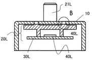
図2は本実施例1に係るステレオカメラの概略構成を示す図、図3は本実施例のステレオカメラの片方のカメラ(左側)の筐体とカメラモジュールの構成を示す図、図4Aは筐体へのモジュールの固定方法を説明する断面図、図4Bは図4AのA−A断面図、図4Cは図4Bの領域Bの拡大図である。 FIG. 2 is a diagram showing a schematic configuration of a stereo camera according to the first embodiment, FIG. 3 is a diagram showing a housing and a camera module configuration of one camera (left side) of the stereo camera of the present embodiment, and FIG. 4A is a housing. A cross-sectional view illustrating a method of fixing the module to the body, FIG. 4B is a cross-sectional view taken along the line AA of FIG. 4A, and FIG. 4C is an enlarged view of a region B of FIG. 4B.
図2において、ステレオカメラ100は、一対の撮像部(左撮像部10L,右撮像部10R)を有しており、左撮像部10L,右撮像部10Rは筐体10に固定されている。
In FIG. 2, the
次に、図3以降を用いて、撮像部におけるカメラモジュールと筐体との関係について左撮像部10Lを例にして説明する。
Next, the relationship between the camera module and the housing in the image pickup unit will be described with reference to FIGS. 3 and 3 by taking the left
右撮像部10Rの構造は、左撮像部10Lの構造を左右対称にしたものであり、その詳細な説明は省略する。
The structure of the
図3乃至図4Cに示すように、左撮像部10Lでは、筐体10とカメラモジュール20Lとが、ネジなどの部材によって係合されておらず、接着剤充填部12L,13L,14L内の接着剤50Lによって互いの位置関係が固定されたものである。
As shown in FIGS. 3 to 4C, in the
図3および図4Bに示すように、カメラモジュール20Lは、レンズ28Lと、レンズ28Lを保持するレンズホルダ21Lと、撮像素子40Lが実装された基板30Lと、から構成される。
As shown in FIGS. 3 and 4B, the
カメラモジュール20Lは、対をなすカメラモジュール20Rとの距離が、求める距離に位置するように高精度に調整され、かつ互いの光軸が平行となるように、光軸方向回転ずれ(ロール角)が補正されている。ここでロール角の調整は、レンズ28Lの入力面側から、撮像素子40Lの碁盤目状に並ぶ画素を観測し、ここから撮像素子40Lの回転方向ずれを求めることで補正される。
The
カメラモジュール20Rとカメラモジュール20Lは、同じ構成であり、並べて配置される。
The camera module 20R and the
図3および図4Aに示すように、レンズホルダ21Lには、レンズ28Lの光軸を法線とする、少なくとも1カ所以上の基準面22L,23L,24Lが3カ所形成されている。この基準面22L,23L,24Lは、カメラモジュール20Lの光軸方向から見たときに、3カ所の基準面22L,23L,24Lのそれぞれの中心を結ぶ三角形領域内に、レンズ28Lや撮像素子40Lが配置される位置関係となっている。
As shown in FIGS. 3 and 4A, the
この基準面22L,23L,24Lは、図4Cに示すように、流動性のある接着剤50Lが接着剤充填部14Lに充填される際にカメラモジュール20L側に漏れだすことがない、すなわち筐体10に設定された接着剤充填部14Lをカメラモジュール20L側の基準面24Lによって蓋がされるように、その面積が各々対応する接着剤充填部12L,13L,14Lより大きくとられている。
As shown in FIG. 4C, the reference surfaces 22L, 23L, and 24L do not leak to the
接着剤50Lは、光硬化性、もしくは光硬化性と熱硬化性を併せ持つ接着剤である。 The adhesive 50L is an adhesive having photocurability or both photocurability and thermosetting.
基板30Lや撮像素子40Lは、レンズ28Lに入力された画像情報が撮像素子40L上で結像されるように光軸、ピント、傾き(6軸;煽り(θx・θy)、高さ(Z)、平面位置(X・Y・θz))が高精度に調整されており、接着剤によりカメラモジュール20Lに対して固定されている。撮像素子40Lは、画像を取得するCMOS(Complementary Metal Oxide Semiconductor)等から構成される。
The
図3に戻り、筐体10は、挿通孔11Lと、対向面15L,16L,17Lと、接着剤充填部12L,13L,14Lとが形成されている。挿通孔11Lは、カメラモジュール20Lのレンズホルダ21Lのうちレンズ28Lを保持する鏡筒を挿通するための孔である。
Returning to FIG. 3, the
対向面15L,16L,17Lは、基準面22L,23L,24Lに対向する光軸が法線となっている面であり、この対向面15L,16L,17Lがカメラモジュール20Lのレンズ28Lの光軸を法線とする共通の基準面22L,23L,24Lに倣う形で組み付けられる。
The facing surfaces 15L, 16L, and 17L are surfaces whose optical axes facing the reference surfaces 22L, 23L, and 24L are normals, and the facing
接着剤充填部12L,13L,14Lは、対向面15L,16L,17L側からその反対面側まで光軸方向に平行に貫通している孔であり、カメラモジュール20Lの基準面22L,23L,24Lに対応して3個形成されている。
The
本実施例では、高精度に位置調整された一対のカメラモジュール20L,20Rは、接着剤充填部12L,13L,14Lに接着剤50Lが充填されることで筐体10に接着固定されている。
In this embodiment, the pair of
本発明では、一対のカメラモジュール20R,20Lの位置精度を高めるために、筐体10は高精度に加工されたものを用いるのではなく、一対のカメラモジュール20R,20Lの位置精度を治具とカメラモジュール20R,20Lに設けた位置決め部材とで決めた状態を保ち、そこに筐体10を組み合わせることとする。
In the present invention, in order to improve the position accuracy of the pair of
また、カメラモジュール20R,20Lは、レンズ28L面と逆側よりチャッキングし、レンズ28L面側から筐体10をかぶせる構造がとられている。
Further, the
位置調整が施された一対のカメラモジュール20R,20Lに組み合わされる筐体10には、接着剤50Lが充填される接着剤充填部12L,13L,14Lがカメラモジュール20R,20Lの光軸方向に設定されており、カメラモジュール20R,20Lの前面側より、接着剤50Lで高精度に一対のカメラモジュール20R,20Lを筐体10に対して固定する。
以下、左側のカメラモジュール20Lを例に、カメラモジュール20Lの筐体10への取付け方について図3乃至図4Cを用いて説明する。
Hereinafter, how to attach the
上述のように、筐体10には、カメラモジュール20Lのレンズ28Lを筐体10の外側に出すための挿通孔11Lが設定されている。ここで挿通孔11Lはカメラモジュール20Lのレンズ28Lを筐体10の外側に出すためだけの挿通孔であるため、挿通孔11Lの位置精度、径精度が高精度に作製されている必要はない。
As described above, the
接着の詳細を接着剤充填部14Lで説明する。
The details of the adhesion will be described with reference to the
カメラモジュール20Lのレンズホルダ21Lを挿通孔11Lに挿通させると、筐体10に設定された接着剤充填部14Lは、カメラモジュール20L側の基準面24Lで蓋を形成される形となり、流動性のある接着剤50Lが充填されてもカメラモジュール20L側に漏れだすことはない。
When the
接着剤50Lの充填時および硬化時は、接着剤充填部14Lとカメラモジュール20Lの基準面24Lとにより形成されるコップ上の形態から接着剤50Lが漏れ出さないように、光軸を重力方向に一致させ、筐体10を上方向、カメラモジュール20Lを下方向の向きにすることが望ましい。
When filling and curing the adhesive 50L, the optical axis is oriented in the direction of gravity so that the adhesive 50L does not leak from the shape on the cup formed by the
接着剤充填部12L,13Lについても同様に接着剤を充填し、硬化させる。
The
接着剤を硬化させた後、一対のカメラモジュール20L,20Rの固定治具を解除すれば、筐体10に、高精度な位置決めされた姿勢を保ったカメラモジュール20L,20Rが接着された状態が完成する。
After curing the adhesive, if the fixing jigs of the pair of
次に、本実施例の効果について説明する。 Next, the effect of this embodiment will be described.
上述した本発明の実施例1のステレオカメラ100は、レンズ28L、およびレンズ28Lの光軸を法線とする、少なくとも1カ所以上の基準面22L,23L,24Lが形成されているレンズホルダ21Lを有するカメラモジュール20R,20Lと、レンズホルダ21Lを挿通する挿通孔11L、基準面22L,23L,24Lに対向する対向面15L,16L,17L、対向面15L,16L,17L側から対向面15L,16L,17Lの反対面側まで貫通する接着剤充填部12L,13L,14Lを有する筐体10と、を備える。
The
このように、レンズ28Lの光軸を法線とする、少なくとも1カ所以上の基準面22L,23L,24Lが形成されているレンズホルダ21Lと、基準面22L,23L,24Lに対向する対向面15L,16L,17L、対向面15L,16L,17L側から対向面15L,16L,17Lの反対面側まで貫通する接着剤充填部12L,13L,14Lを有する筐体10とを接着剤50Lによって固定することによって、筐体10への精密な加工、もしくは成型を極力抑えて低コスト化を図ることが出来、且つ筐体10に対する一対のカメラモジュール20R,20Lの高精度な光軸調整が行われたものとすることができる。
In this way, the
また、カメラモジュール20R,20Lは基準面22L,23L,24Lが3カ所形成されており、筐体10は接着剤充填部12L,13L,14Lを3個有しているため、筐体10に対する一対のカメラモジュール20R,20Lの光軸調整をより高精度に、且つ手間をかけることなく行うことができる。
Further, since the
更に、基準面22L,23L,24Lは、レンズ28Lおよび撮像素子40Lを囲むように配置されていることで、筐体10に対する一対のカメラモジュール20R,20Lの光軸調整をより高精度に行うことができる。
Further, since the reference surfaces 22L, 23L, and 24L are arranged so as to surround the
<実施例2>
本発明の実施例2のステレオカメラについて図5A乃至図5Cを用いて説明する。実施例1と同じ構成には同一の符号を示し、説明は省略する。以下の実施例においても同様とする。図5Aは本実施例2に係るステレオカメラの特徴的構造を説明する図、図5Bは図5AのC−C断面図、図5Cは図5Bの領域Dの拡大図である。<Example 2>
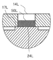
The stereo camera of the second embodiment of the present invention will be described with reference to FIGS. 5A to 5C. The same reference numerals are shown in the same configurations as in the first embodiment, and the description thereof will be omitted. The same applies to the following examples. 5A is a diagram illustrating a characteristic structure of the stereo camera according to the second embodiment, FIG. 5B is a sectional view taken along the line CC of FIG. 5A, and FIG. 5C is an enlarged view of a region D of FIG. 5B.
実施例1のステレオカメラ100と本実施例のステレオカメラでは、カメラモジュールの基準面の表面形状が異なる。その他の構成・動作は前述した実施例1のステレオカメラ100と略同じ構成・動作であり、詳細は省略する。
The surface shape of the reference surface of the camera module is different between the
以下、実施例1のステレオカメラ100との相違点について図5A乃至図5Cを用いて説明する。
Hereinafter, the differences from the
図5Aおよび図5Bに示す本実施例のカメラモジュール20L1では、レンズホルダ21L1に保持されるレンズの光軸を法線とする基準面24L1上に、図5Cに示すように、凹形状25L1、およびその内部に基準面24L1より窪んだ高さの凸形状26L1が形成されている。凹形状25L1および凸形状26L1は、筐体10の接着剤充填部14Lから基準面24L1を覗いた際に目印となる位置に形成されている。
In the camera module 20L1 of the present embodiment shown in FIGS. 5A and 5B, the concave shape 25L1 and the concave shape 25L1 as shown in FIG. A convex shape 26L1 having a height recessed from the reference surface 24L1 is formed inside the reference surface 24L1. The concave shape 25L1 and the convex shape 26L1 are formed at positions that serve as marks when the reference surface 24L1 is viewed from the
凸形状26L1は、基準面24L1と同一面か、それ以下の高さとすることが望ましいが、基準面24L1より高いものであってもよい。 The convex shape 26L1 preferably has the same height as or lower than the reference surface 24L1, but may be higher than the reference surface 24L1.
接着剤充填部12L,13Lに対応する残る2ヶ所の基準面上にも、それぞれ凹形状およびその内部に凸形状を設ける。
A concave shape and a convex shape inside the concave shape are also provided on the remaining two reference surfaces corresponding to the
本実施例においても、筐体10に設定された接着剤充填部14Lは、カメラモジュール20L1側の基準面24L1で蓋を形成される形となり、流動性のある接着剤52Lが充填されてもカメラモジュール側に漏れだすことはない。
Also in this embodiment, the
接着剤52Lは光硬化性、もしくは光硬化性と熱硬化性を併せ持つ接着剤である。 The adhesive 52L is a photocurable adhesive or an adhesive having both photocurability and thermosetting property.
本発明の実施例2のステレオカメラにおいても、前述した実施例1のステレオカメラ100とほぼ同様な効果が得られる。
The stereo camera of the second embodiment of the present invention also has almost the same effect as the
また、基準面24L1は、その表面に凹形状25L1を有することにより、凹形状25L1は接着剤52Lのアンカーとなり、Z方向を光軸方向とした場合、X,Y方向の動きを抑制するとともに、接着面積を大きく取れることから、接着強度をより高める事が可能となる。 Further, since the reference surface 24L1 has a concave shape 25L1 on its surface, the concave shape 25L1 serves as an anchor for the adhesive 52L, and when the Z direction is the optical axis direction, the movement in the X and Y directions is suppressed and the movement is suppressed. Since a large adhesive area can be obtained, it is possible to further increase the adhesive strength.
更に、基準面24L1は、凹形状25L1内に基準面24L1より窪んだ凸形状26L1を有することで、接着剤充填前に、凸形状26L1を位置観測用マーカーとして使用することができ、光軸調整の際の位置決め精度をより容易かつ高精度に行うことができる。
また、凸形状26L1についても接着剤52Lのアンカーとなり、接着強度を更に高める事が可能となる。Further, since the reference surface 24L1 has a convex shape 26L1 recessed from the reference surface 24L1 in the concave shape 25L1, the convex shape 26L1 can be used as a marker for position observation before filling with the adhesive, and the optical axis can be adjusted. The positioning accuracy at the time of the above can be performed more easily and with high accuracy.
Further, the convex shape 26L1 also serves as an anchor for the adhesive 52L, and the adhesive strength can be further increased.
なお、3つの基準面に同じように凹形状および凸形状を設ける場合について説明したが、複数の基準面に設ける凹形状や凸形状はすべての基準面に設ける必要はなく、基準面すべてに凹形状のみを設けたり、凹形状のみの基準面と凹形状および凸形状を設けた基準面と凹形状および凸形状を設けていない基準面とを混在させたりすることができる。また、設ける凹形状や凸形状は各々の基準面で全て同じである必要はなく、適宜形状を変えることができる。 Although the case where the concave shape and the convex shape are provided on the three reference surfaces in the same manner has been described, it is not necessary to provide the concave shape and the convex shape provided on the plurality of reference surfaces on all the reference surfaces, and the concave shape and the convex shape are provided on all the reference surfaces. It is possible to provide only the shape, or to mix a reference surface having only a concave shape, a reference surface having a concave shape and a convex shape, and a reference surface having no concave shape and a convex shape. Further, the concave shape and the convex shape to be provided do not have to be the same on each reference surface, and the shape can be changed as appropriate.
<実施例3>
本発明の実施例3のステレオカメラについて図6A乃至図6Cを用いて説明する。図6Aは本実施例3に係るステレオカメラの特徴的構造を説明する図、図6Bは図6AのE−E断面図、図6Cは図6Bの領域Fの拡大図である。<Example 3>
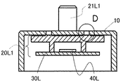
The stereo camera of the third embodiment of the present invention will be described with reference to FIGS. 6A to 6C. 6A is a diagram illustrating a characteristic structure of the stereo camera according to the third embodiment, FIG. 6B is a sectional view taken along line EE of FIG. 6A, and FIG. 6C is an enlarged view of a region F of FIG. 6B.
実施例1のステレオカメラ100と本実施例のステレオカメラでは、カメラモジュールの基準面の表面形状が異なる。その他の構成・動作は前述した実施例1のステレオカメラ100と略同じ構成・動作であり、詳細は省略する。
The surface shape of the reference surface of the camera module is different between the
以下、実施例1のステレオカメラ100との相違点について図6A乃至図6Bを用いて説明する。
Hereinafter, the differences from the
図6Aおよび図6Bに示す本実施例のカメラモジュール20L2では、レンズホルダ21L2に保持されるレンズの光軸を法線とする基準面24L2上に、図6Cに示すように、凸形状27L2が形成されている。凸形状27L2は、筐体10の接着剤充填部14Lから基準面24L2を覗いた際に目印となる位置に形成されている。
In the camera module 20L2 of this embodiment shown in FIGS. 6A and 6B, a convex shape 27L2 is formed on a reference surface 24L2 whose normal axis is the optical axis of the lens held by the lens holder 21L2, as shown in FIG. 6C. Has been done. The convex shape 27L2 is formed at a position that serves as a mark when the reference surface 24L2 is viewed from the
凸形状27L2は、基準面24L2以上の高さであればよく、接着剤54Lよりも高くても低くてもよい。 The convex shape 27L2 may have a height of the reference surface 24L2 or more, and may be higher or lower than the adhesive 54L.
接着剤充填部12L,13Lに対応する残る2ヶ所の基準面上にも、それぞれ凸形状を設ける。
Convex shapes are also provided on the remaining two reference surfaces corresponding to the
本実施例においても、筐体10に設定された接着剤充填部14Lは、カメラモジュール20L2側の基準面24L2で蓋を形成される形となり、流動性のある接着剤54Lが充填されてもカメラモジュール側に漏れだすことはない。
Also in this embodiment, the
接着剤54Lは光硬化性、もしくは光硬化性と熱硬化性を併せ持つ接着剤である。 The adhesive 54L is a photocurable adhesive or an adhesive having both photocurability and thermosetting property.
本発明の実施例3のステレオカメラにおいても、前述した実施例1のステレオカメラ100とほぼ同様な効果が得られる。
The stereo camera of the third embodiment of the present invention also has almost the same effect as the
また、基準面24L2は、その表面に凸形状27L2を有することにより、凸形状27L2は接着剤54Lのアンカーとなり、Z方向を光軸方向とした場合、X,Y方向の動きを抑制するとともに、接着面積を大きく取れることができるため、接着強度を高める事が可能となる。 Further, since the reference surface 24L2 has a convex shape 27L2 on its surface, the convex shape 27L2 serves as an anchor for the adhesive 54L, and when the Z direction is the optical axis direction, the movement in the X and Y directions is suppressed and the movement is suppressed. Since a large adhesive area can be obtained, it is possible to increase the adhesive strength.
なお、3つの基準面に同じように凸形状を設ける場合について説明したが、凸形状はすべての基準面に設ける必要はなく、一部の基準面のみに凸形状を設けることができる。また、設ける凸形状は各々の基準面で全て同じである必要はなく、適宜形状を変えることができる。 Although the case where the convex shape is provided on the three reference surfaces in the same manner has been described, it is not necessary to provide the convex shape on all the reference surfaces, and the convex shape can be provided only on a part of the reference surfaces. Further, the convex shape to be provided does not have to be the same on each reference surface, and the shape can be changed as appropriate.
<その他>
なお、本発明は、上記の実施例に限定されるものではなく、様々な変形例が含まれる。
上記の実施例は本発明を分かりやすく説明するために詳細に説明したものであり、必ずしも説明した全ての構成を備えるものに限定されるものではない。<Others>
The present invention is not limited to the above examples, and includes various modifications.
The above-mentioned examples have been described in detail in order to explain the present invention in an easy-to-understand manner, and are not necessarily limited to those having all the described configurations.
また、ある実施例の構成の一部を他の実施例の構成に置き換えることも可能であり、また、ある実施例の構成に他の実施例の構成を加えることも可能である。また、各実施例の構成の一部について、他の構成の追加・削除・置換をすることも可能である。 It is also possible to replace a part of the configuration of one embodiment with the configuration of another embodiment, and it is also possible to add the configuration of another embodiment to the configuration of one embodiment. It is also possible to add / delete / replace a part of the configuration of each embodiment with another configuration.
例えば、車載撮像装置はカメラモジュールが2つ設けられたステレオカメラの場合について説明したが、車載撮像装置はステレオカメラである必要はなく、車載撮像装置の用途に応じて適宜カメラモジュールを設けることができる。 For example, the case where the in-vehicle image pickup device is a stereo camera provided with two camera modules has been described, but the in-vehicle image pickup device does not have to be a stereo camera, and the in-vehicle image pickup device may be appropriately provided with a camera module according to the application of the in-vehicle image pickup device. can.
また、1つのカメラモジュールにつき基準面を3ヶ所、接着剤充填部を3個設定する場合について説明したが、これら基準面や接着剤充填部は一つのカメラモジュールに対して3ずつ設定する必要はない。 In addition, although the case where three reference planes and three adhesive filling portions are set for one camera module has been described, it is necessary to set three reference planes and three adhesive filling portions for one camera module. No.
例えば、基準面についてはその面積次第で1つのカメラモジュールにつき1ヶ所(カメラモジュールの対向面と接する面すべてを基準面として加工)設定することができ、また2ヶ所や4ヶ所以上設定することができる。 For example, depending on the area of the reference surface, one location can be set for each camera module (all surfaces in contact with the facing surface of the camera module are processed as reference surfaces), and two or four or more locations can be set. can.
また、接着剤充填部についても、1つのカメラモジュールにつき2個設定することができ、この場合カメラモジュールを囲むような形状であることが望ましい。また接着剤充填部を4個以上設定することも可能である。 In addition, two adhesive filling portions can be set for each camera module, and in this case, it is desirable that the shape surrounds the camera module. It is also possible to set four or more adhesive-filled portions.
10…筐体、10L…左撮像部、10R…右撮像部、11L…挿通孔(挿通部)、12L,13L,14L…接着剤充填部、15L,16L,17L…対向面、20R,20L,20L1,20L2…カメラモジュール(撮像素子部)、21L、21L1,21L2…レンズホルダ、22L,23L,24L,24L1,24L2…基準面、25L1…凹形状(凹状部)、26L1…凸形状(凸状部)、27L2…凸形状(凸状部)、28L…レンズ、30L…基板、40L…撮像素子、50L,52L,54L…接着剤、100…ステレオカメラ(車載撮像装置)、200…車両 10 ... Housing, 10L ... Left image sensor, 10R ... Right image sensor, 11L ... Insertion hole (insertion part), 12L, 13L, 14L ... Adhesive filling part, 15L, 16L, 17L ... Facing surface, 20R, 20L, 20L1, 20L2 ... Camera module (image sensor), 21L, 21L1,21L2 ... Lens holder, 22L, 23L, 24L, 24L1,24L2 ... Reference surface, 25L1 ... Concave shape (concave part), 26L1 ... Convex shape (convex shape) Part), 27L2 ... Convex shape (convex part), 28L ... Lens, 30L ... Substrate, 40L ... Image sensor, 50L, 52L, 54L ... Adhesive, 100 ... Stereo camera (vehicle-mounted image sensor), 200 ... Vehicle
Claims (7)
前記レンズホルダを挿通する挿通部、前記基準面に対向する対向面、前記対向面側から前記対向面の反対面側まで貫通する、前記挿通部を囲むように配置されている3個の接着剤充填部を有する筐体と、を備え、
前記撮像素子部と前記筐体とは、3個の前記接着剤充填部内の接着剤によってのみ互いの位置関係が固定された
ことを特徴とする車載撮像装置。 Lenses, and the optical axis of the lens and normal, have a lens holder reference surface of the three points that are arranged so as to surround the lens is formed when viewed from the direction of the optical axis of the lens Image sensor and
Insertion portion for inserting the lens holder, facing surface that faces the reference surface, said penetrating from a surface facing to the opposite side of the facing surface, three of adhesive being arranged so as to surround the insertion portion With a housing having a filling part ,
An in-vehicle image pickup device characterized in that the positional relationship between the image pickup element portion and the housing is fixed only by the adhesives in the three adhesive filling portions.
前記基準面は、その表面に凹状部を有する
ことを特徴とする車載撮像装置。 In the in-vehicle imaging device according to claim 1,
An in-vehicle imaging device characterized in that the reference surface has a concave portion on the surface thereof.
前記基準面は、前記凹状部内に前記基準面より窪んだ凸状部を有する
ことを特徴とする車載撮像装置。 In the in-vehicle imaging device according to claim 2,
An in-vehicle imaging device, wherein the reference surface has a convex portion recessed from the reference surface in the concave portion.
前記基準面は、その表面に凸状部を有する
ことを特徴とする車載撮像装置。 In the in-vehicle imaging device according to claim 1,
An in-vehicle imaging device characterized in that the reference surface has a convex portion on the surface thereof.
3カ所の前記基準面すべてに前記凸状部が設けられている The convex portion is provided on all three reference surfaces.
ことを特徴とする車載撮像装置。 An in-vehicle imaging device characterized by this.
3カ所の前記基準面のうち、前記凸状部が設けられている前記基準面は一部である Of the three reference surfaces, the reference surface provided with the convex portion is a part.
ことを特徴とする車載撮像装置。 An in-vehicle imaging device characterized by this.
前記撮像素子部は、第1撮像素子部および前記第1撮像素子部と同じ構成の第2撮像素子部を有し、
前記第1撮像素子部および前記第2撮像素子部は、互いの光軸が平行となるように並べて配置されている
ことを特徴とする車載撮像装置。 The in-vehicle imaging device according to any one of claims 1 to 6.
The image sensor unit has a first image sensor unit and a second image sensor unit having the same configuration as the first image sensor unit.
An in-vehicle image sensor, wherein the first image sensor and the second image sensor are arranged side by side so that their optical axes are parallel to each other.
Applications Claiming Priority (3)
| Application Number | Priority Date | Filing Date | Title |
|---|---|---|---|
| JP2017215019 | 2017-11-07 | ||
| JP2017215019 | 2017-11-07 | ||
| PCT/JP2018/039271 WO2019093113A1 (en) | 2017-11-07 | 2018-10-23 | In-vehicle image pickup device |
Publications (2)
| Publication Number | Publication Date |
|---|---|
| JPWO2019093113A1 JPWO2019093113A1 (en) | 2020-11-12 |
| JP6941686B2 true JP6941686B2 (en) | 2021-09-29 |
Family
ID=66437704
Family Applications (1)
| Application Number | Title | Priority Date | Filing Date |
|---|---|---|---|
| JP2019552694A Active JP6941686B2 (en) | 2017-11-07 | 2018-10-23 | In-vehicle imaging device |
Country Status (4)
| Country | Link |
|---|---|
| US (1) | US11543616B2 (en) |
| JP (1) | JP6941686B2 (en) |
| DE (1) | DE112018004595B4 (en) |
| WO (1) | WO2019093113A1 (en) |
Families Citing this family (5)
| Publication number | Priority date | Publication date | Assignee | Title |
|---|---|---|---|---|
| TWI693826B (en) * | 2018-11-14 | 2020-05-11 | 明泰科技股份有限公司 | Blind zone imaging device with adjustment ring |
| JP2022146480A (en) * | 2021-03-22 | 2022-10-05 | リコーインダストリアルソリューションズ株式会社 | stereo camera device |
| KR20230009132A (en) * | 2021-07-08 | 2023-01-17 | 엘지이노텍 주식회사 | Camera module |
| DE102022207679A1 (en) | 2022-07-27 | 2024-02-01 | Zf Friedrichshafen Ag | Sensor mounting device |
| JP2024070005A (en) * | 2022-11-10 | 2024-05-22 | 日立Astemo株式会社 | On-vehicle camera device and manufacturing method of on-vehicle camera device |
Family Cites Families (17)
| Publication number | Priority date | Publication date | Assignee | Title |
|---|---|---|---|---|
| JP2001242521A (en) | 2000-02-28 | 2001-09-07 | Fuji Heavy Ind Ltd | Assemblage structure of camera, camera adjusting method, and adjusting jig |
| JP3821718B2 (en) * | 2002-01-28 | 2006-09-13 | セイコープレシジョン株式会社 | Solid-state imaging device |
| JP2005274612A (en) * | 2004-03-22 | 2005-10-06 | Olympus Corp | Imaging device and manufacturing method therefor |
| JP2006251367A (en) * | 2005-03-10 | 2006-09-21 | Fuji Photo Film Co Ltd | Camera |
| JP2008020837A (en) * | 2006-07-14 | 2008-01-31 | Fujifilm Corp | Camera |
| DE102013200966B4 (en) * | 2012-02-10 | 2023-11-16 | Robert Bosch Gmbh | Module device for a camera system and corresponding camera system |
| JP6056860B2 (en) | 2012-07-31 | 2017-01-11 | ソニー株式会社 | Lens mounting mechanism, lens mounting method, and imaging apparatus |
| JP5793122B2 (en) * | 2012-07-31 | 2015-10-14 | 日立オートモティブシステムズ株式会社 | In-vehicle image processing device |
| JP6657100B2 (en) * | 2014-09-25 | 2020-03-04 | 日本電産コパル株式会社 | Imaging device, optical device, electronic device, vehicle, and method of manufacturing imaging device |
| WO2016109790A1 (en) | 2014-12-31 | 2016-07-07 | Gentex Corporation | Rear vehicle camera |
| US9715078B2 (en) * | 2015-05-14 | 2017-07-25 | Microsoft Technology Licensing, Llc | Adjustable lens mount |
| US9986136B2 (en) * | 2015-10-30 | 2018-05-29 | Magna Electronics Inc. | Vehicle camera with single point imager fixation to lens holder |
| CN111062304A (en) * | 2016-02-26 | 2020-04-24 | 亚马逊技术有限公司 | Sharing video recordings from audio/video recording and communication devices |
| JP6591340B2 (en) * | 2016-04-15 | 2019-10-16 | 日立オートモティブシステムズ株式会社 | Multi-eye optical device |
| JP6630226B2 (en) * | 2016-04-27 | 2020-01-15 | 日立オートモティブシステムズ株式会社 | Imaging module and imaging device |
| US10321029B2 (en) * | 2017-05-01 | 2019-06-11 | Logitech Europe S.A. | Modular coupling for a video camera system |
| JP6942604B2 (en) * | 2017-10-24 | 2021-09-29 | 日立Astemo株式会社 | Imaging device, multi-eye imaging device |
-
2018
- 2018-10-23 JP JP2019552694A patent/JP6941686B2/en active Active
- 2018-10-23 US US16/652,859 patent/US11543616B2/en active Active
- 2018-10-23 DE DE112018004595.1T patent/DE112018004595B4/en active Active
- 2018-10-23 WO PCT/JP2018/039271 patent/WO2019093113A1/en active Application Filing
Also Published As
| Publication number | Publication date |
|---|---|
| US20200310069A1 (en) | 2020-10-01 |
| WO2019093113A1 (en) | 2019-05-16 |
| US11543616B2 (en) | 2023-01-03 |
| JPWO2019093113A1 (en) | 2020-11-12 |
| DE112018004595T5 (en) | 2020-07-09 |
| DE112018004595B4 (en) | 2024-04-25 |
Similar Documents
| Publication | Publication Date | Title |
|---|---|---|
| JP6941686B2 (en) | In-vehicle imaging device | |
| US10589696B2 (en) | On-vehicle image processing device | |
| US10077008B2 (en) | Windshield-mounted camera apparatus and adjuster | |
| JP4667430B2 (en) | In-vehicle camera | |
| US10365462B2 (en) | Distance measurement system and mobile object system | |
| JP2015193366A (en) | Manufacturing method of box body for on-vehicle camera, box body for on-vehicle camera, and on-vehicle camera | |
| JP2011123078A (en) | Stereo camera | |
| EP3070524B1 (en) | Imaging unit, vehicle control unit and heat transfer method for imaging unit | |
| US10992920B2 (en) | Stereo image processing device | |
| JP2018013623A (en) | On-vehicle imaging device | |
| CN112970241B (en) | Vehicle-mounted camera | |
| JP2013127598A (en) | Stereo camera | |
| JP6062314B2 (en) | Imaging device | |
| JP7532926B2 (en) | Imaging unit and vehicle control unit | |
| US20220274528A1 (en) | Vehicle-mounted camera and method of manufacturing the same | |
| JP6158258B2 (en) | In-vehicle image processing device | |
| JP2018189908A (en) | Imaging device | |
| JP6430586B2 (en) | Stereo vision system for cars | |
| CN219018914U (en) | Trinocular camera based on optical axis parallelism adjustment | |
| WO2022249743A1 (en) | Imaging device and vehicle-mounted system | |
| KR101517130B1 (en) | Safety driving system for vehicles | |
| US20200065987A1 (en) | Signal processing apparatus, moving body, and stereo camera | |
| TW201607803A (en) | Auxiliary driving device and rear view mirror integration module |
Legal Events
| Date | Code | Title | Description |
|---|---|---|---|
| A621 | Written request for application examination |
Free format text: JAPANESE INTERMEDIATE CODE: A621 Effective date: 20200330 |
|
| A131 | Notification of reasons for refusal |
Free format text: JAPANESE INTERMEDIATE CODE: A131 Effective date: 20210511 |
|
| A521 | Request for written amendment filed |
Free format text: JAPANESE INTERMEDIATE CODE: A523 Effective date: 20210615 |
|
| TRDD | Decision of grant or rejection written | ||
| A01 | Written decision to grant a patent or to grant a registration (utility model) |
Free format text: JAPANESE INTERMEDIATE CODE: A01 Effective date: 20210810 |
|
| A61 | First payment of annual fees (during grant procedure) |
Free format text: JAPANESE INTERMEDIATE CODE: A61 Effective date: 20210906 |
|
| R150 | Certificate of patent or registration of utility model |
Ref document number: 6941686 Country of ref document: JP Free format text: JAPANESE INTERMEDIATE CODE: R150 |
|
| R250 | Receipt of annual fees |
Free format text: JAPANESE INTERMEDIATE CODE: R250 |