JP6940493B2 - Methods and systems for configuring I / O abstraction field devices - Google Patents

Methods and systems for configuring I / O abstraction field devices Download PDF

Info

Publication number
JP6940493B2
JP6940493B2 JP2018519794A JP2018519794A JP6940493B2 JP 6940493 B2 JP6940493 B2 JP 6940493B2 JP 2018519794 A JP2018519794 A JP 2018519794A JP 2018519794 A JP2018519794 A JP 2018519794A JP 6940493 B2 JP6940493 B2 JP 6940493B2
Authority
JP
Japan
Prior art keywords
field
field device
commissioning
environment
devices
Prior art date
Legal status (The legal status is an assumption and is not a legal conclusion. Google has not performed a legal analysis and makes no representation as to the accuracy of the status listed.)
Active
Application number
JP2018519794A
Other languages
Japanese (ja)
Other versions
JP2018534682A5 (en
JP2018534682A (en
Inventor
オー. ユント,ラリー
オー. ユント,ラリー
イアン エス. ウイ,クリストファー
イアン エス. ウイ,クリストファー
アール. コルクレイジャー,デボラ
アール. コルクレイジャー,デボラ
ディアス,セルジオ
ケー. ロウ,ゲーリー
ケー. ロウ,ゲーリー
ケー. ナイドー,ジュリアン
ケー. ナイドー,ジュリアン
アール. ストリンデン,ダニエル
アール. ストリンデン,ダニエル
エー. バール,ケント
エー. バール,ケント
ジェイ. ピーターソン,ネイル
ジェイ. ピーターソン,ネイル
Original Assignee
フィッシャー−ローズマウント システムズ,インコーポレイテッド
Priority date (The priority date is an assumption and is not a legal conclusion. Google has not performed a legal analysis and makes no representation as to the accuracy of the date listed.)
Filing date
Publication date
Application filed by フィッシャー−ローズマウント システムズ,インコーポレイテッド, フィッシャー−ローズマウント システムズ,インコーポレイテッド filed Critical フィッシャー−ローズマウント システムズ,インコーポレイテッド
Publication of JP2018534682A publication Critical patent/JP2018534682A/en
Publication of JP2018534682A5 publication Critical patent/JP2018534682A5/ja
Application granted granted Critical
Publication of JP6940493B2 publication Critical patent/JP6940493B2/en
Active legal-status Critical Current
Anticipated expiration legal-status Critical

Links

Images

Classifications

    • GPHYSICS
    • G05CONTROLLING; REGULATING
    • G05BCONTROL OR REGULATING SYSTEMS IN GENERAL; FUNCTIONAL ELEMENTS OF SUCH SYSTEMS; MONITORING OR TESTING ARRANGEMENTS FOR SUCH SYSTEMS OR ELEMENTS
    • G05B19/00Programme-control systems
    • G05B19/02Programme-control systems electric
    • G05B19/418Total factory control, i.e. centrally controlling a plurality of machines, e.g. direct or distributed numerical control [DNC], flexible manufacturing systems [FMS], integrated manufacturing systems [IMS], computer integrated manufacturing [CIM]
    • G05B19/41865Total factory control, i.e. centrally controlling a plurality of machines, e.g. direct or distributed numerical control [DNC], flexible manufacturing systems [FMS], integrated manufacturing systems [IMS], computer integrated manufacturing [CIM] characterised by job scheduling, process planning, material flow
    • GPHYSICS
    • G05CONTROLLING; REGULATING
    • G05BCONTROL OR REGULATING SYSTEMS IN GENERAL; FUNCTIONAL ELEMENTS OF SUCH SYSTEMS; MONITORING OR TESTING ARRANGEMENTS FOR SUCH SYSTEMS OR ELEMENTS
    • G05B19/00Programme-control systems
    • G05B19/02Programme-control systems electric
    • G05B19/418Total factory control, i.e. centrally controlling a plurality of machines, e.g. direct or distributed numerical control [DNC], flexible manufacturing systems [FMS], integrated manufacturing systems [IMS], computer integrated manufacturing [CIM]
    • G05B19/4185Total factory control, i.e. centrally controlling a plurality of machines, e.g. direct or distributed numerical control [DNC], flexible manufacturing systems [FMS], integrated manufacturing systems [IMS], computer integrated manufacturing [CIM] characterised by the network communication
    • GPHYSICS
    • G05CONTROLLING; REGULATING
    • G05BCONTROL OR REGULATING SYSTEMS IN GENERAL; FUNCTIONAL ELEMENTS OF SUCH SYSTEMS; MONITORING OR TESTING ARRANGEMENTS FOR SUCH SYSTEMS OR ELEMENTS
    • G05B19/00Programme-control systems
    • G05B19/02Programme-control systems electric
    • G05B19/418Total factory control, i.e. centrally controlling a plurality of machines, e.g. direct or distributed numerical control [DNC], flexible manufacturing systems [FMS], integrated manufacturing systems [IMS], computer integrated manufacturing [CIM]
    • GPHYSICS
    • G05CONTROLLING; REGULATING
    • G05BCONTROL OR REGULATING SYSTEMS IN GENERAL; FUNCTIONAL ELEMENTS OF SUCH SYSTEMS; MONITORING OR TESTING ARRANGEMENTS FOR SUCH SYSTEMS OR ELEMENTS
    • G05B19/00Programme-control systems
    • G05B19/02Programme-control systems electric
    • G05B19/04Programme control other than numerical control, i.e. in sequence controllers or logic controllers
    • G05B19/042Programme control other than numerical control, i.e. in sequence controllers or logic controllers using digital processors
    • G05B19/0423Input/output
    • GPHYSICS
    • G05CONTROLLING; REGULATING
    • G05BCONTROL OR REGULATING SYSTEMS IN GENERAL; FUNCTIONAL ELEMENTS OF SUCH SYSTEMS; MONITORING OR TESTING ARRANGEMENTS FOR SUCH SYSTEMS OR ELEMENTS
    • G05B19/00Programme-control systems
    • G05B19/02Programme-control systems electric
    • G05B19/18Numerical control [NC], i.e. automatically operating machines, in particular machine tools, e.g. in a manufacturing environment, so as to execute positioning, movement or co-ordinated operations by means of programme data in numerical form
    • G05B19/414Structure of the control system, e.g. common controller or multiprocessor systems, interface to servo, programmable interface controller
    • GPHYSICS
    • G05CONTROLLING; REGULATING
    • G05BCONTROL OR REGULATING SYSTEMS IN GENERAL; FUNCTIONAL ELEMENTS OF SUCH SYSTEMS; MONITORING OR TESTING ARRANGEMENTS FOR SUCH SYSTEMS OR ELEMENTS
    • G05B19/00Programme-control systems
    • G05B19/02Programme-control systems electric
    • G05B19/418Total factory control, i.e. centrally controlling a plurality of machines, e.g. direct or distributed numerical control [DNC], flexible manufacturing systems [FMS], integrated manufacturing systems [IMS], computer integrated manufacturing [CIM]
    • G05B19/4183Total factory control, i.e. centrally controlling a plurality of machines, e.g. direct or distributed numerical control [DNC], flexible manufacturing systems [FMS], integrated manufacturing systems [IMS], computer integrated manufacturing [CIM] characterised by data acquisition, e.g. workpiece identification
    • GPHYSICS
    • G05CONTROLLING; REGULATING
    • G05BCONTROL OR REGULATING SYSTEMS IN GENERAL; FUNCTIONAL ELEMENTS OF SUCH SYSTEMS; MONITORING OR TESTING ARRANGEMENTS FOR SUCH SYSTEMS OR ELEMENTS
    • G05B19/00Programme-control systems
    • G05B19/02Programme-control systems electric
    • G05B19/418Total factory control, i.e. centrally controlling a plurality of machines, e.g. direct or distributed numerical control [DNC], flexible manufacturing systems [FMS], integrated manufacturing systems [IMS], computer integrated manufacturing [CIM]
    • G05B19/4185Total factory control, i.e. centrally controlling a plurality of machines, e.g. direct or distributed numerical control [DNC], flexible manufacturing systems [FMS], integrated manufacturing systems [IMS], computer integrated manufacturing [CIM] characterised by the network communication
    • G05B19/4186Total factory control, i.e. centrally controlling a plurality of machines, e.g. direct or distributed numerical control [DNC], flexible manufacturing systems [FMS], integrated manufacturing systems [IMS], computer integrated manufacturing [CIM] characterised by the network communication by protocol, e.g. MAP, TOP
    • GPHYSICS
    • G05CONTROLLING; REGULATING
    • G05BCONTROL OR REGULATING SYSTEMS IN GENERAL; FUNCTIONAL ELEMENTS OF SUCH SYSTEMS; MONITORING OR TESTING ARRANGEMENTS FOR SUCH SYSTEMS OR ELEMENTS
    • G05B23/00Testing or monitoring of control systems or parts thereof
    • G05B23/02Electric testing or monitoring
    • G05B23/0205Electric testing or monitoring by means of a monitoring system capable of detecting and responding to faults
    • G05B23/0218Electric testing or monitoring by means of a monitoring system capable of detecting and responding to faults characterised by the fault detection method dealing with either existing or incipient faults
    • G05B23/0224Process history based detection method, e.g. whereby history implies the availability of large amounts of data
    • GPHYSICS
    • G06COMPUTING; CALCULATING OR COUNTING
    • G06KGRAPHICAL DATA READING; PRESENTATION OF DATA; RECORD CARRIERS; HANDLING RECORD CARRIERS
    • G06K7/00Methods or arrangements for sensing record carriers, e.g. for reading patterns
    • G06K7/10Methods or arrangements for sensing record carriers, e.g. for reading patterns by electromagnetic radiation, e.g. optical sensing; by corpuscular radiation
    • G06K7/10009Methods or arrangements for sensing record carriers, e.g. for reading patterns by electromagnetic radiation, e.g. optical sensing; by corpuscular radiation sensing by radiation using wavelengths larger than 0.1 mm, e.g. radio-waves or microwaves
    • G06K7/10366Methods or arrangements for sensing record carriers, e.g. for reading patterns by electromagnetic radiation, e.g. optical sensing; by corpuscular radiation sensing by radiation using wavelengths larger than 0.1 mm, e.g. radio-waves or microwaves the interrogation device being adapted for miscellaneous applications
    • HELECTRICITY
    • H04ELECTRIC COMMUNICATION TECHNIQUE
    • H04LTRANSMISSION OF DIGITAL INFORMATION, e.g. TELEGRAPHIC COMMUNICATION
    • H04L41/00Arrangements for maintenance, administration or management of data switching networks, e.g. of packet switching networks
    • H04L41/08Configuration management of networks or network elements
    • H04L41/0803Configuration setting
    • H04L41/0806Configuration setting for initial configuration or provisioning, e.g. plug-and-play
    • HELECTRICITY
    • H04ELECTRIC COMMUNICATION TECHNIQUE
    • H04LTRANSMISSION OF DIGITAL INFORMATION, e.g. TELEGRAPHIC COMMUNICATION
    • H04L67/00Network arrangements or protocols for supporting network services or applications
    • H04L67/01Protocols
    • H04L67/12Protocols specially adapted for proprietary or special-purpose networking environments, e.g. medical networks, sensor networks, networks in vehicles or remote metering networks
    • GPHYSICS
    • G05CONTROLLING; REGULATING
    • G05BCONTROL OR REGULATING SYSTEMS IN GENERAL; FUNCTIONAL ELEMENTS OF SUCH SYSTEMS; MONITORING OR TESTING ARRANGEMENTS FOR SUCH SYSTEMS OR ELEMENTS
    • G05B2219/00Program-control systems
    • G05B2219/30Nc systems
    • G05B2219/31From computer integrated manufacturing till monitoring
    • G05B2219/31121Fielddevice, field controller, interface connected to fieldbus
    • GPHYSICS
    • G05CONTROLLING; REGULATING
    • G05BCONTROL OR REGULATING SYSTEMS IN GENERAL; FUNCTIONAL ELEMENTS OF SUCH SYSTEMS; MONITORING OR TESTING ARRANGEMENTS FOR SUCH SYSTEMS OR ELEMENTS
    • G05B2219/00Program-control systems
    • G05B2219/30Nc systems
    • G05B2219/32Operator till task planning
    • G05B2219/32252Scheduling production, machining, job shop
    • YGENERAL TAGGING OF NEW TECHNOLOGICAL DEVELOPMENTS; GENERAL TAGGING OF CROSS-SECTIONAL TECHNOLOGIES SPANNING OVER SEVERAL SECTIONS OF THE IPC; TECHNICAL SUBJECTS COVERED BY FORMER USPC CROSS-REFERENCE ART COLLECTIONS [XRACs] AND DIGESTS
    • Y02TECHNOLOGIES OR APPLICATIONS FOR MITIGATION OR ADAPTATION AGAINST CLIMATE CHANGE
    • Y02PCLIMATE CHANGE MITIGATION TECHNOLOGIES IN THE PRODUCTION OR PROCESSING OF GOODS
    • Y02P90/00Enabling technologies with a potential contribution to greenhouse gas [GHG] emissions mitigation
    • Y02P90/02Total factory control, e.g. smart factories, flexible manufacturing systems [FMS] or integrated manufacturing systems [IMS]
    • YGENERAL TAGGING OF NEW TECHNOLOGICAL DEVELOPMENTS; GENERAL TAGGING OF CROSS-SECTIONAL TECHNOLOGIES SPANNING OVER SEVERAL SECTIONS OF THE IPC; TECHNICAL SUBJECTS COVERED BY FORMER USPC CROSS-REFERENCE ART COLLECTIONS [XRACs] AND DIGESTS
    • Y02TECHNOLOGIES OR APPLICATIONS FOR MITIGATION OR ADAPTATION AGAINST CLIMATE CHANGE
    • Y02PCLIMATE CHANGE MITIGATION TECHNOLOGIES IN THE PRODUCTION OR PROCESSING OF GOODS
    • Y02P90/00Enabling technologies with a potential contribution to greenhouse gas [GHG] emissions mitigation
    • Y02P90/80Management or planning

Description

<関連出願の相互参照>
本出願は、「Smart Commissioning of Process Control Plants」という名称で、2015年10月12日に出願された米国特許出願第62/240,084号に対する優先権、及びその利益を主張するものであり、その開示全体は、参照により本明細書に組み込まれる。
<Cross-reference of related applications>
This application, under the name "Smart Communication of Process Control Plants", claims priority over US Patent Application No. 62 / 240,084 filed on October 12, 2015, and its benefits. The entire disclosure is incorporated herein by reference.

本出願は、「Commissioning Field Devices in a Process Control System Supported by Big Data」という名称で、2015年1月26日に出願された米国特許出願第14/605,304号、及び本出願と同時に出願され、「Method and System for Commissioning Process Control Hardware」(代理人整理番号06005−593481)という名称の米国特許出願第15/291,200号に関するものであり、これらの開示全体は、参照により本明細書に組み込まれる。 This application is filed under the name of "Commissioning Field Devices in a Process Control System Supported by Big Data", and is filed at the same time as US Patent Application No. 14 / 605,304 filed on January 26, 2015, and this application. , US Patent Application No. 15 / 291,200, entitled "Method and System for Control Processing Process Control Hardware" (agent reference number 0600-593481), the entire disclosure of which is hereby incorporated by reference. Be incorporated.

<技術分野>
本開示は、一般に、プロセスプラント及びプロセス制御システムに関し、より具体的には、プロセスプラント及びプロセス制御システムのフィールドデバイス及びループのスマートまたはインテリジェントコミッショニングに関する。
<Technical field>
The present disclosure relates generally to process plants and process control systems, and more specifically to smart or intelligent commissioning of field devices and loops in process plants and process control systems.

物理的材料もしくは製品を製造、精製、変換、生成、または生産するために、化学、石油、工業、または他のプロセスプラントにおいて使用されるような分散型プロセス制御システムは、典型的に、アナログ、デジタル、もしくは複合アナログ/デジタルバスを介して、または無線通信リンクもしくはネットワークを介して、1つ以上のフィールドデバイスに通信的に結合された1つ以上のプロセスコントローラを含む。例えば弁、弁ポジショナ、スイッチ、及び伝送器(例えば、温度、圧力、レベル、及び流量センサ)であり得るフィールドデバイスは、プロセス環境内に位置付けられ、一般に、弁の開閉、温度もしくは圧力等のプロセス及び/または環境パラメータの測定等の物理的もしくはプロセス制御機能を行って、プロセスプラントまたはシステム内で実行する1つ以上のプロセスを制御する。広く公知のフィールドバスプロトコルに準拠したフィールドデバイス等のスマートフィールドデバイスは、制御計算、アラーム機能、及び一般にコントローラ内に実装される他の制御機能も行い得る。典型的にプラント環境内にも位置付けられるプロセスコントローラは、フィールドデバイスによって行われるプロセス測定及び/またはフィールドデバイスに関係する他の情報を示す信号を受信し、例えば、プロセス制御の決定を下し、受信した情報に基づいて制御信号を生成し、フィールドデバイス内で行われている制御モジュールまたはブロックと協調する異なる制御モジュール(HART(登録商標)、WirelessHART(登録商標)、及びFOUNDATION(登録商標)フィールドバスフィールドデバイス等)を実行するコントローラアプリケーションを実行する。コントローラ内の制御モジュールは、通信回線またはリンクを通じて制御信号をフィールドデバイスに送り、それによって、プロセスプラントまたはシステムの少なくとも一部分の動作を制御して、例えば、プラントまたはシステム内で動作または実行する1つ以上の工業プロセスの少なくとも一部分を制御する。例えば、コントローラ及びフィールドデバイスは、プロセスプラントまたはシステムによって制御されているプロセスの少なくとも一部分を制御する。典型的にプラント環境内にも位置付けられるI/Oデバイスは、典型的に、コントローラと1つ以上のフィールドデバイスとの間に配置され、例えば電気信号をデジ
タル値に、及びその逆に変換することによって、それらの間の通信を可能にする。本明細書で利用されるとき、フィールドデバイス、コントローラ、及びI/Oデバイスは、一般に、「プロセス制御デバイス」と称され、また、一般に、プロセス制御システムまたはプラントのフィールド環境内に位置付けられ、配置され、または設置される。
Distributed process control systems, such as those used in chemical, petrochemical, industrial, or other process plants to manufacture, refine, convert, produce, or produce physical materials or products, are typically analog. Includes one or more process controllers communicatively coupled to one or more field devices via a digital or composite analog / digital bus, or via a wireless communication link or network. Field devices, which can be, for example, valves, valve positioners, switches, and transmitters (eg, temperature, pressure, level, and flow rate sensors) are positioned within the process environment and are generally processes such as valve opening and closing, temperature or pressure, etc. And / or perform physical or process control functions such as measuring environmental parameters to control one or more processes running within a process plant or system. Smart field devices, such as field devices that comply with widely known fieldbus protocols, may also perform control calculations, alarm functions, and other control functions commonly implemented within the controller. A process controller, typically also located within a plant environment, receives signals indicating process measurements and / or other information related to the field device made by the field device, eg, making and receiving process control decisions. Different control modules (HART®, WirelessHART®, and FOUNDATION® fieldbus) that generate control signals based on the information provided and cooperate with control modules or blocks performed within the field device. Run the controller application that runs the field device, etc.). A control module within a controller sends a control signal to a field device through a communication line or link, thereby controlling the operation of at least a portion of a process plant or system, eg, one operating or performing within the plant or system. Control at least part of the above industrial process. For example, controllers and field devices control at least a portion of a process controlled by a process plant or system. I / O devices, typically also located within the plant environment, are typically placed between the controller and one or more field devices, eg, converting electrical signals to digital values and vice versa. Allows communication between them. As used herein, field devices, controllers, and I / O devices are commonly referred to as "process control devices" and are generally positioned and deployed within the field environment of a process control system or plant. Or installed.

フィールドデバイス及びコントローラからの情報は、通常、オペレータワークステーション、パーソナルコンピュータもしくはコンピューティングデバイス、データヒストリアン、レポート生成器、集中データベース、または典型的により過酷なプラントのフィールド環境から離れた制御室に、例えばプロセスプラントのバックエンド環境に配置される他の集中管理コンピューティングデバイス等の、1つ以上の他のハードウェアデバイスへのデータハイウェイもしくは通信ネットワークを通じて利用できるようにされる。これらのハードウェアデバイスの各々は、典型的に、プロセスプラント全体にわたって、またはプロセスプラントの一部分にわたって集中化される。これらのハードウェアデバイスは、例えば、プロセス制御ルーチンの設定変更、コントローラもしくはフィールドデバイス内の制御モジュールの動作の修正、プロセスの現在の状態の確認、フィールドデバイス及びコントローラによって生成されるアラームの確認、人員の訓練またはプロセス制御ソフトウェアの試験の目的でのプロセスの動作のシミュレーション、構成データベースの維持及び更新等の、プロセスの制御及び/またはプロセスプラントの動作に関する機能を、オペレータが行うことを可能にすることができる、アプリケーションを実行する。ハードウェアデバイス、コントローラ、及びフィールドデバイスによって利用されるデータハイウェイとしては、有線通信経路、無線通信経路、または有線通信経路及び無線通信経路の組み合わせが挙げられ得る。 Information from field devices and controllers is typically in an operator workstation, personal computer or computing device, data historian, report generator, centralized database, or control room away from the field environment of a typical more harsh plant. It will be made available through a data highway or communication network to one or more other hardware devices, such as other centralized computing devices located in the back-end environment of a process plant. Each of these hardware devices is typically centralized over the entire process plant or over a portion of the process plant. These hardware devices include, for example, changing the settings of process control routines, modifying the behavior of control modules in controllers or field devices, checking the current state of processes, checking field devices and alarms generated by controllers, personnel. Allowing operators to perform functions related to process control and / or process plant operation, such as simulating process operation, maintaining and updating configuration databases, for the purpose of training or testing process control software. Can run the application. Data highways utilized by hardware devices, controllers, and field devices can include wired communication paths, wireless communication paths, or combinations of wired and wireless communication paths.

一例として、Emerson Process Managementによって販売されるDeltaV(商標)制御システムは、プロセスプラント内の様々な場所に位置付けられる異なるデバイスの内部に記憶され、それによって実行される複数のアプリケーションを含む。プロセス制御システムもしくはプラントのバックエンド環境において1つ以上のワークステーションまたはコンピューティングデバイス内に存在する構成アプリケーションは、ユーザが、プロセス制御モジュールを作成または変更し、これらのプロセス制御モジュールを、データハイウェイを介して、専用の分散型コントローラにダウンロードすることを可能にする。典型的には、これらの制御モジュールは、通信的に相互接続される機能ブロックから構成され、これらの機能ブロックは、オブジェクト指向プログラミングプロトコルにおけるオブジェクトであり、制御スキーム内でそれに対する入力に基づいて機能を行い、制御スキーム内の他の機能ブロックに出力を提供する。構成アプリケーションはまた、構成の設計者が、オペレータにデータを表示するために閲覧アプリケーションによって使用されるオペレータインターフェースを作成または変更することを可能にすること、及びオペレータが、プロセス制御ルーチン内の設定値等の設定を変更することを可能にすることもできる。各専用のコントローラ、及びいくつかの事例において1つ以上のフィールドデバイスは、それらに指定され、ダウンロードされる制御モジュールを実行するそれぞれのコントローラアプリケーションを記憶し、実行して、実際のプロセス制御機能を実装する。1つ以上のオペレータワークステーション上で(またはオペレータワークステーション及びデータハイウェイと通信的に接続している1つ以上のリモートコンピューティングデバイス上で)実行することができる閲覧アプリケーションは、データハイウェイを介して、コントローラアプリケーションからデータを受信し、そして、ユーザインターフェースを使用して、このデータをプロセス制御システムの設計者、オペレータ、またはユーザに表示し、また、オペレータの画面、エンジニアの画面、及び技術者の画面等の、いくつかの異なる画面のうちのいずれかを提供することができる。データヒストリアンアプリケーションは、典型的に、データハイウェイ全体にわたって提供されるデータの一部または全部を収集し、記憶する、データヒストリアンデバイスに記憶され、それによって実行され、一方で、構成データベースアプリケーションは、データハイウェイに取り
付けられるさらなるコンピュータで実行して、現在のプロセス制御ルーチン構成及びそれと関連付けられるデータを記憶することができる。代替的に、構成データベースは、構成アプリケーションと同じワークステーションに配置することができる。
As an example, the Delta V ™ control system sold by Emerson Process Management includes multiple applications stored and executed within different devices located at various locations within the process plant. Configuration applications that reside within one or more workstations or computing devices in a process control system or plant back-end environment allow the user to create or modify process control modules and transfer these process control modules to the data highway. Through, it is possible to download to a dedicated distributed controller. Typically, these control modules consist of functional blocks that are communicatively interconnected, and these functional blocks are objects in an object-oriented programming protocol that function based on the inputs to them within the control scheme. And provide output to other functional blocks in the control scheme. The configuration application also allows the designer of the configuration to create or modify the operator interface used by the browsing application to display data to the operator, and the operator can set values in the process control routine. It is also possible to change the settings such as. Each dedicated controller, and in some cases one or more field devices, remembers and executes each controller application that runs the control module specified and downloaded to them to provide the actual process control function. Implement. Browsing applications that can run on one or more operator workstations (or on one or more remote computing devices that are communicatively connected to the operator workstation and data highway) are via the data highway. , Receives data from the controller application, and uses the user interface to display this data to the designer, operator, or user of the process control system, as well as the operator's screen, engineer's screen, and technician's screen. Any of several different screens, such as screens, can be provided. A data historian application typically collects and stores some or all of the data provided across the data highway, stored in and executed by a data historian device, while a configuration database application Can be run on additional computers attached to the data highway to store the current process control routine configuration and associated data. Alternatively, the configuration database can be located on the same workstation as the configuration application.

一般に、プロセスプラントまたはシステムのコミッショニングは、プラントまたはシステムの様々なコンポーネントを、システムまたはプラントを意図するように動作させることができる地点に持ってくることを伴う。一般的に知られているように、物理的プロセス要素(プロセスプラント内のプロセスを制御するために利用される弁、センサ等)は、例えばプラントフロアレイアウト及び/もしくはプロセスレイアウトの配管及び計装図(P&ID)ならびに/または他の計画もしくは「青写真」に従って、プラントのフィールド環境内のそれぞれの場所に設置される。プロセス要素が設置された後には、プロセス要素の少なくとも一部がコミッショニングされる。例えば、フィールドデバイス、サンプリング点、及び/または他の要素は、コミッショニングを受ける。コミッショニングは、典型的に複数のアクションまたはアクティビティを含む、入り組んだ複雑なプロセスである。例えば、コミッショニングは、とりわけ、設置されたプロセス制御デバイス(フィールドデバイス等)及びその予想される接続の識別を検証または確認すること、プロセス制御システムまたはプラント内のプロセス制御デバイスを一意的に識別するタグを決定し、提供すること、デバイスのパラメータ、限度等の初期値を設定または構成すること、例えばデバイスに提供される信号を操作し、他の試験を行うことによって、様々な条件下で、デバイスの設置、動作、及び挙動の正確性を検証すること、及び他のコミッショニングアクティビティ及びアクション等の、アクションまたはアクティビティを含み得る。コミッショニング中のデバイス検証は、安全性の理由から、ならびに規制及び品質要件に準拠するために重要である。 In general, commissioning a process plant or system involves bringing the plant or various components of the system to a point where the system or plant can operate as intended. As is generally known, physical process elements (valves, sensors, etc. used to control processes within a process plant) are, for example, plant floor layouts and / or process layout piping and instrumentation drawings. (P & ID) and / or installed at each location within the field environment of the plant according to other plans or "blueprints". After the process element is installed, at least part of the process element is commissioned. For example, field devices, sampling points, and / or other elements are commissioned. Commissioning is a complex and complex process that typically involves multiple actions or activities. For example, commissioning, among other things, verifies or confirms the identification of installed process control devices (such as field devices) and their expected connections, tags that uniquely identify process control systems or process control devices within a plant. Under various conditions, by determining and providing, setting or configuring initial values such as device parameters, limits, etc., for example by manipulating the signals provided to the device and performing other tests. It may include actions or activities such as verifying the accuracy of installation, operation, and behavior of, and other commissioning activities and actions. Device verification during commissioning is important for safety reasons as well as to comply with regulatory and quality requirements.

他のコミッショニングアクションまたはアクティビティは、デバイスが含まれるプロセス制御ループ上で行われる。このようなコミッショニングアクションまたはアクティビティは、例えば、いくつか例を挙げれば、相互接続全体にわたって送信される様々な信号が、相互接続の両端において予想される挙動をもたらすことを検証すること、プロセス制御ループに関する完全性検査、プラント内に実装されるデバイスの実際の物理的接続を示すための現況I/Oリストを生成すること、ならびに、他の「設置時の」データを記録することを含む。 Other commissioning actions or activities take place on the process control loop that contains the device. Such commissioning actions or activities, for example, verifying that the various signals transmitted throughout the interconnect produce the expected behavior at both ends of the interconnect, process control loops, to name a few. Includes integrity checking for, generating an as-is I / O list to show the actual physical connectivity of the devices implemented in the plant, and recording other "installation" data.

いくつかのコミッショニング作業のために、ユーザは、様々な目標のプロセス制御デバイス、コンポーネント、及びループにおいてローカルにコミッショニングツール(例えば、ハンドヘルドまたはポータブルコンピューティングデバイス)を利用することができる。いくつかのコミッショニング作業は、プロセス制御システムのオペレータインターフェースにおいて、例えばプロセスプラントのバックエンド環境に含まれるオペレータワークステーションのオペレータインターフェースにおいて行うことができる。 For some commissioning tasks, users can utilize commissioning tools (eg, handheld or portable computing devices) locally in process control devices, components, and loops for various goals. Some commissioning operations can be performed on the operator interface of the process control system, eg, on the operator interface of the operator workstation included in the back-end environment of the process plant.

典型的に、プロセスプラントのコミッショニングは、プロセスプラントのフィールド環境において設置され、設定され、相互接続される、物理的デバイス、接続、配線等が必要である。プラントのバックエンド環境において(例えば、典型的に制御室の中に、またはプラントのより過酷なフィールド環境から離れた他の場所にある、オペレータワークステーション、パーソナルコンピュータもしくはコンピューティングデバイス、集中データベース、構成ツール等の、集中管理コンピューティングデバイスにおいて)、特に、様々なデバイス、該デバイスの構成、及び該デバイスの相互接続を識別し、及び/または該デバイスをアドレス指定するデータが集積され、検証またはコミッショニングされ、そして記憶される。このように、物理的ハードウェアが設置され、構成された後に、様々なデバイスが他のデバイスと通信することができるように、識別情報、論理命令、ならびに他の命令及び/またはデータがダウンロードされ、または別様には、フィールド環境内に配置さ
れる様々なデバイスに提供される。
Typically, process plant commissioning requires physical devices, connections, wiring, etc. that are installed, configured, and interconnected in the process plant field environment. Operator workstations, personal computers or computing devices, centralized databases, configurations in the back-end environment of the plant (eg, typically in the control room or elsewhere away from the plant's more harsh field environment). Data is aggregated, validated or commissioned to identify and / or address various devices, their configurations, and their interconnects), especially in centralized computing devices such as tools). And remembered. In this way, after the physical hardware is installed and configured, identification information, logical instructions, and other instructions and / or data are downloaded so that various devices can communicate with other devices. , Or otherwise, it is provided to various devices placed in the field environment.

当然ながら、バックエンド環境において行われるコミッショニングアクションに加えて、コミッショニングアクションまたはアクティビティも行われて、個別的及び一体的の両方で、物理的デバイス及び論理的デバイス両方のフィールド環境における接続及び動作の正確性を検証する。例えば、フィールドデバイスは、物理的に設置され、例えば電源オン、電源オフ等が個別に検証され得る。フィールドデバイスの一部は、次いで、コミッショニングツールに物理的に接続することができ、それを介して、シミュレーションされた信号をフィールドデバイスに送信することができ、様々なシミュレーションされた信号に応答するフィールドデバイスの挙動を試験することができる。同様に、その通信ポートがコミッショニングされるフィールドデバイスは、最終的に、端子ブロックに物理的に接続して、端子ブロックとフィールドデバイスとの間の実際の通信を試験することができる。典型的に、フィールド環境におけるフィールドデバイス及び/または他のコンポーネントのコミッショニングは、試験信号及び応答をフィールドデバイス及び他のループコンポーネントの間で通信し、また、結果として生じる検証された挙動を通信することができるように、コンポーネントの識別に関する知識、及びいくつかの事例では、コンポーネントの相互接続に関する知識を必要とする。現在公知のコミッショニング技術において、このような識別及び相互接続の知識またはデータは、一般に、バックエンド環境によってフィールド環境内のコンポーネントに提供される。例えば、バックエンド環境は、制御モジュールにおいて使用されるフィールドデバイスタグを、実際のプラント動作中に制御モジュールによって制御されるフィールドデバイスにダウンロードする。 Of course, in addition to the commissioning actions performed in the back-end environment, commissioning actions or activities are also performed to accurately connect and operate in the field environment of both physical and logical devices, both individually and integrally. Verify sex. For example, the field device can be physically installed and, for example, power on, power off, etc. can be individually verified. Some of the field devices can then be physically connected to a commissioning tool through which the simulated signal can be sent to the field device and the field responding to various simulated signals. You can test the behavior of the device. Similarly, the field device to which its communication port is commissioned can eventually be physically connected to the terminal block to test the actual communication between the terminal block and the field device. Typically, commissioning of field devices and / or other components in a field environment communicates test signals and responses between field devices and other loop components, and also communicates the resulting verified behavior. Requires knowledge of component identification, and in some cases knowledge of component interconnection so that it can be done. In currently known commissioning techniques, such identification and interconnection knowledge or data is generally provided by the back-end environment to components within the field environment. For example, the backend environment downloads the field device tags used in the control module to the field devices controlled by the control module during actual plant operation.

最終的に、プロセス制御ループの様々なコンポーネント及び部分をそれぞれコミッショニングし、検査し、試験した後に、ループ自体の全体をコミッショニングし、検査し、及び/または試験し、例えば「ループ試験」する。典型的に、ループ試験は、様々な入力または条件に応答する、及び/または様々な状態におけるループの挙動を試験することを含む。バックエンド環境のオペレータは、フィールド環境のオペレータと協調して、プロセス制御ループにおいて、様々な入力を注入し、及び/または様々な条件及び/または状態を生成し、そして、許容可能な目標値及び/または範囲に対するそれらの一致レベルについて、結果として生じた挙動及び/または測定値を調査する。 Finally, after commissioning, inspecting, and testing the various components and parts of the process control loop, respectively, the entire loop itself is commissioned, inspected, and / or tested, eg, "loop tested". Loop testing typically involves testing the behavior of the loop in response to different inputs or conditions and / or in different conditions. Operators in the back-end environment work with operators in the field environment to inject different inputs and / or generate different conditions and / or states in the process control loop, and tolerate target values and Investigate the resulting behavior and / or measurements for their level of coincidence with respect to the range.

スマートコミッショニング(「インテリジェントコミッショニング」または「パラレルコミッショニング」とも称される)のための技術、システム、装置、コンポーネント、デバイス、及び方法を本明細書で開示する。本技術、システム、装置、コンポーネント、デバイス、及び方法は、工業プロセス制御システム、環境、及び/またはプラントに適用することができ、これらは、本明細書において、互換的に「工業制御」、「プロセス制御」、「プロセス」システム、環境、及び/またはプラントと称される。典型的に、そのようなシステム及びプラントは、物理的原材料を製造、精製、または変換して製品を生成または生産するように動作する1つ以上のプロセス(本明細書において、「工業プロセス」とも称される)の分散方式における制御を提供する。 Techniques, systems, devices, components, devices, and methods for smart commissioning (also referred to as "intelligent commissioning" or "parallel commissioning") are disclosed herein. The technology, systems, equipment, components, devices, and methods can be applied to industrial process control systems, environments, and / or plants, which are interchangeably referred to herein as "industrial control", ". Referred to as "process control", "process" system, environment, and / or plant. Typically, such systems and plants are one or more processes that operate to produce, refine, or convert physical raw materials to produce or produce products (also referred to herein as "industrial processes". Provides control in a distributed scheme (referred to).

プロセス制御システム及び/またはプラントのスマートコミッショニングは、コミッショニングプロセスの少なくともいくつかの部分を、ローカルに、自動的に、及び/または分配的に行うことを可能にし、よって、プロセスプラントのデバイス、コンポーネント、及び他の部分を、プラントまたはシステムの中へ全体的に組み込むまたは統合する前に、部分的に、さらには全体的にコミッショニングすることができる、様々な技術、システム、装置、コンポーネント、及び/または方法を含む。スマートコミッショニングは、例えば、プロセス制御システム及び/またはそれらのそれぞれの安全計装システム(SIS)(例えば、スタンドアロンまたは一体型安全システム(ICSS))の様々な部分を、プ
ロセスプラントの所在場所またはサイトにおいてまとめられ、統合される前に、異なる地理的な場所(例えば、異なる「modヤード」)において構築し、少なくとも部分的にコミッショニングすることを可能にする。ある意味では、スマート/インテリジェントコミッショニングは、並行のコミッショニングアクティビティ及びアクションを行うことを可能にする。
Smart commissioning of process control systems and / or plants allows at least some part of the commissioning process to take place locally, automatically and / or in a distributed manner, and thus the devices, components of the process plant. And various technologies, systems, equipment, components, and / or that can be partially or even entirely commissioned before being incorporated or integrated entirely into the plant or system. Including methods. Smart commissioning allows, for example, various parts of process control systems and / or their respective safety instrumented systems (SIS) (eg, stand-alone or integrated safety systems (ICSS)) at the location or site of the process plant. Allows it to be built in different geographic locations (eg, different "mod yards") and at least partially commissioned before being put together and integrated. In a sense, smart / intelligent commissioning allows for parallel commissioning activities and actions.

例えば、スマートコミッショニングは、(大部分ではなくとも)いくつかのコミッショニングアクティビティ及び/またはアクションを、プロセスプラントのフィールド環境において、及びバックエンド環境において独立に(及び実際には、所望に応じて、並行して)行うことを可能にする。フィールド環境に実装される設計及びエンジニアリングのコミッショニングは、もはや、バックエンド環境において行われて大部分が完了した機能的設計、エンジニアリング、及びコミッショニングの進捗(及び完了)に依存しない。このように、フィールド環境の物理的なコンポーネントのローカルコミッショニングアクティビティのかなりの部分を、バックエンド環境の機能的または論理的なコンポーネントのコミッショニングとは独立に行うことができ、逆もまた同様に行うことができる。すなわち、フィールド環境またはバックエンド環境のいずれかにおけるコミッショニングアクティビティ及びアクションの少なくともいくつかの部分は、フィールド環境及びバックエンド環境が通信的に切断されている間に、例えば、フィールド環境に設置された(または設置されている)ループ(またはその一部分)がバックエンド環境から通信的に切断されている間に行うことができる。例えば、スマートコミッショニング技術を使用すると、フィールド環境及び/またはバックエンド環境におけるコミッショニングアクティビティまたはアクションの少なくともいくつかの部分を、プロセス制御システムまたはプラントが、特定のI/Oカード及び/またはチャネルへのフィールドデバイスの指定に関する知識を有する前に行うことができる。 For example, smart commissioning allows some (if not most) commissioning activities and / or actions to be performed independently (and, in fact, as desired) in the field environment of the process plant and in the back-end environment. And make it possible to do. Design and engineering commissions implemented in the field environment no longer depend on the progress (and completion) of functional design, engineering, and commissioning that has been done and mostly completed in the back-end environment. In this way, a significant portion of the local commissioning activity of the physical components of the field environment can be done independently of the commissioning of the functional or logical components of the backend environment, and vice versa. Can be done. That is, at least some of the commissioning activities and actions in either the field environment or the back-end environment were installed, for example, in the field environment while the field environment and the back-end environment were communicatively disconnected (ie). Or it can be done while the (or installed) loop (or part thereof) is communicatively disconnected from the backend environment. For example, using smart commissioning technology, a process control system or plant can field at least some of the commissioning activities or actions in a field environment and / or backend environment to a particular I / O card and / or channel. This can be done before having knowledge of device specification.

同様に、プロセスプラントのプロセス制御ループに関して、スマートコミッショニングは、ループのコンポーネントの全てを最初に設置し、相互接続することを必要とすることなく、様々なコミッショニングアクティビティ及び/またはアクションを、ループの様々なコンポーネント及び部分に対して行うことを可能にする。故に、プロセス制御ループのコミッショニングアクティビティの少なくともいくつかの部分は、プロセス制御ループの様々なコンポーネントが切断されている間に、または互いに、ループに、及び/もしくはバックエンド環境にまだ割り当てられていない間に行うことができる。例えば、それぞれのコミッショニングアクティビティは、プロセスプラントのバックエンド環境及びフィールド環境が通信的に切断されている間、これらの2つの環境の両方において開始し、行うことができる。フィールド環境及びバックエンド環境は、それらのそれぞれの側のプロセス制御ループの様々なそれぞれの部分を同時にコミッショニングし、次いで、2つの側の結合に応じて、行われる残りのコミッショニングアクティビティの大部分は、全体としてループに従うコミッショニングアクティビティである。 Similarly, with respect to process control loops in a process plant, smart commissioning can perform various commissioning activities and / or actions in various loops without the need to first install and interconnect all of the loop's components. Allows you to do for various components and parts. Therefore, at least some part of the commissioning activity of the process control loop is while the various components of the process control loop are disconnected or not yet assigned to each other, to the loop, and / or to the backend environment. Can be done. For example, each commissioning activity can be initiated and performed in both of these two environments while the process plant's back-end and field environments are communicatively disconnected. The field and back-end environments simultaneously commission various parts of the process control loop on their respective sides, and then most of the remaining commissioning activity that takes place in response to the combination of the two sides. It is a commissioning activity that follows a loop as a whole.

さらに、スマートコミッショニングは、いかなるユーザ入力も必要とすることなく、特定の条件に基づいて、特定のコミッショニングアクション及びアクティビティを自動的にトリガーまたは開始することを可能にする。いくつかの状況において、多数のコミッショニングアクション及び/アクティビティは、ユーザが次にどのアクティビティを、どのコンポーネントに対して、及びどのように行うのかを示すことを必要とすることなく、自動的にトリガーし、実行することができる。 In addition, smart commissioning allows specific commissioning actions and activities to be automatically triggered or initiated based on specific conditions without the need for any user input. In some situations, numerous commissioning actions and / activities automatically trigger without requiring the user to indicate which activity to perform next, to which component, and how. , Can be executed.

結果的に、スマートコミッショニングが、プロセスプラントのフィールド環境において行われる物理的な設計及びエンジニアリングを、プロセスプラントのバックエンド環境において行われる機能的な設計及びエンジニアリングとは独立に進めることを可能にし、また、スマートコミッショニングが、プロセス制御ループの様々な部分の区分的コミッショ
ニングを、独立に、または設置状態に基づいて行うことも可能にするので、バックエンドとフィールドとの間のコミッショニングスケジューリングの依存性が低減され、また、プロセスプラントをコミッショニングするために必要とされる全体的なカレンダー時間も低減される。したがって、スマートコミッショニングは、時間及び人の両方のリソースの大幅な低減、したがって、コストの大幅な低減を伴って、コミッショニングプロセスを全体的に最適化する。
As a result, smart commissioning allows the physical design and engineering performed in the field environment of the process plant to proceed independently of the functional design and engineering performed in the back-end environment of the process plant. , Smart commissioning also allows piecewise commissioning of various parts of the process control loop to be done independently or based on installation conditions, reducing the dependency of commissioning scheduling between the backend and the field. It also reduces the overall calendar time required to commission the process plant. Therefore, smart commissioning optimizes the commissioning process as a whole, with a significant reduction in both time and human resources, and thus a significant reduction in cost.

本明細書で説明されるスマートコミッショニング技術のうちの1つ以上を利用することによって、その少なくとも一部分がコミッショニングされ得る、例示的なシステムプロセスプラントを図示するブロック図である。FIG. 6 is a block diagram illustrating an exemplary system process plant in which at least a portion thereof can be commissioned by utilizing one or more of the smart commissioning techniques described herein. 図1のプロセスプラントに含まれ得る、及びスマートコミッショニング技術を利用して少なくとも部分的にコミッショニングされ得る、2つの例示的なループのブロック図である。FIG. 2 is a block diagram of two exemplary loops that can be included in the process plant of FIG. 1 and can be commissioned at least partially using smart commissioning techniques. 図1のプロセスプラントに含まれ得る、電子マーシャリングブロックまたは装置の例示的なアーキテクチャを図示する図である。FIG. 5 illustrates an exemplary architecture of an electronic marshalling block or device that may be included in the process plant of FIG. 図1のプロセスプラントに含まれ得る、及びスマートコミッショニング技術を利用して少なくとも部分的にコミッショニングされ得る、2つの例示的なループのブロック図である。FIG. 2 is a block diagram of two exemplary loops that can be included in the process plant of FIG. 1 and can be commissioned at least partially using smart commissioning techniques. 例示的なタグ構文解析装置またはデバイスのブロック図である。It is a block diagram of an exemplary tag parser or device. タグ構文解析の例示的な方法の流れ図である。It is a flow chart of an exemplary method of tag parsing. スマートコミッショニング中に使用され得る、例示的なデバイスコンテナまたはプレースホルダーオブジェクトを図示する図である。FIG. 5 illustrates an exemplary device container or placeholder object that can be used during smart commissioning. プロセスプラントをコミッショニングするための例示的な方法の流れ図である。It is a flow chart of an exemplary method for commissioning a process plant. スマートコミッショニング中に使用され得る、電子マーシャリングコンポーネントのための例示的なエクステンダを図示する図である。FIG. 5 illustrates an exemplary extender for an electronic marshalling component that can be used during smart commissioning. ループがプロセスプラントのバックエンド環境から通信的に切断されている間に、プロセスプラントのフィールド環境においてアズビルトループ情報をローカルに生成するための例示的な方法の流れ図である。It is a flow chart of an exemplary method for locally generating as-built loop information in a process plant field environment while the loop is communicatively disconnected from the process plant backend environment. 例示的なローカルアズビルトループ情報を生成する装置またはデバイスのブロック図である。FIG. 6 is a block diagram of a device or device that generates exemplary local as-built loop information. プロセスプラントをコミッショニングするための例示的な方法の流れ図である。It is a flow chart of an exemplary method for commissioning a process plant. フィールド設備がプラント内のI/Oネットワークを介して接続される前に、及び/または割り当てられる前に、モジュール、アプリケーション、及びインターフェースプログラムなどのバックエンドコンポーネントに対するコミッショニングアクションを構成し、行う能力を提供する、プロセスまたは工業プラントのバックエンドシステム内のコンポーネントの図である。Provides the ability to configure and perform commissioning actions on back-end components such as modules, applications, and interface programs before field equipment is connected and / or assigned over the I / O network within the plant. It is a diagram of a component in a back-end system of a process or industrial plant. フィールド設備がプラント内のI/Oネットワークを介して接続される前に、及び/または割り当てられる前に、モジュール、アプリケーション、及びインターフェースプログラムなどのバックエンドコンポーネントに対するコミッショニングアクションを構成し、行う能力を提供する、プロセスまたは工業プラントのバックエンドシステム内のコンポーネントの図である。Provides the ability to configure and perform commissioning actions on back-end components such as modules, applications, and interface programs before field equipment is connected and / or assigned over the I / O network within the plant. It is a diagram of a component in a back-end system of a process or industrial plant. プラント内のI/Oネットワークを介してフィールド設備が接続及び/または割り当てられる前に、バックエンドシステムコンポーネントを構成し、コミッショニングするときに、フィールド設備へのプロキシとしてデバイスプレースホルダーオブジェクトと通信するためのシステム及び方法の図である。To communicate with the device placeholder object as a proxy to the field equipment when configuring and commissioning the back-end system components before the field equipment is connected and / or assigned over the I / O network in the plant. It is a figure of a system and a method. 確立されたI/Oネットワークを介して、プラントのバックエンドシステム内のオブジェクトをプラント内のフィールド設備と結合させるために、プロセッサまたは工業プラントにおいて使用される結合アプリケーション及びシステムの図である。FIG. 5 is a diagram of combined applications and systems used in a processor or industrial plant to combine objects in the plant's back-end system with field equipment in the plant via an established I / O network. 本明細書で説明される自動ループ試験技術によって1つ以上のプロセス制御ループが試験され得る、例示的なプロセス制御ループを表すブロック図である。FIG. 6 is a block diagram representing an exemplary process control loop in which one or more process control loops can be tested by the automated loop testing techniques described herein. プロセス制御ループを自動的に試験するための例示的な方法の流れ図である。It is a flow chart of an exemplary method for automatically testing a process control loop. 多数のプロセス制御ループを自動的に試験するための例示的な方法の流れ図である。It is a flow chart of an exemplary method for automatically testing a large number of process control loops. 従来のコミッショニング技術を、本明細書で説明されるスマートコミッショニング技術のうちの少なくともいくつかと比較するチャートである。It is a chart comparing a conventional commissioning technique with at least some of the smart commissioning techniques described herein.

上で論じたように、オンラインであるときに、リアルタイムで1つ以上の工業プロセスを制御するように動作するプロセスプラント、プロセス制御システム、またはプロセス制御環境は、本明細書で説明される新規なスマートコミッショニング技術、システム、装置、コンポーネント、デバイス、及び/または方法のうちの1つ以上を利用してコミッショニングすることができる。プロセスプラントは、オンラインでコミッショニングされ、動作するとき、プロセス制御システムと協調して物理的機能を行って、プロセスプラント内で実行する1つ以上のプロセスを制御する、1つ以上の有線もしくは無線プロセス制御デバイス、コンポーネント、または要素を含む。プロセスプラント及び/またはプロセス制御システムは、例えば、1つ以上の有線通信ネットワーク及び1つ以上の無線通信ネットワークを含み得る。加えて、プロセスプラントまたは制御システムは、連続データベース、バッチデータベース、資産管理データベース、ヒストリアンデータベース、及び他のタイプのデータベース等の、集中データベースを含み得る。 As discussed above, process plants, process control systems, or process control environments that operate to control one or more industrial processes in real time when online are novel as described herein. Commissioning can be done using one or more of smart commissioning technologies, systems, devices, components, devices, and / or methods. A process plant is commissioned online and, when operating, one or more wired or wireless processes that work with a process control system to perform physical functions to control one or more processes running within the process plant. Includes control device, component, or element. The process plant and / or process control system may include, for example, one or more wired communication networks and one or more wireless communication networks. In addition, the process plant or control system may include centralized databases such as continuous databases, batch databases, asset management databases, historian databases, and other types of databases.

例示のために、図1は、本明細書で説明されるスマートコミッショニング技術のうちの任意の1つ以上を使用することによって少なくともその一部分がコミッショニングされた、例示的なプロセスプラント、プロセス制御システム、またはプロセス制御環境5のブロック図である。プロセスプラント5は、フィールドデバイスによって作成されたプロセス測定値を示す信号を受信し、この情報を処理して制御ルーチンを実装し、そして、有線または無線プロセス制御通信リンクまたはネットワークを通じて他のフィールドデバイスに送信されてプラント5内のプロセスの動作を制御する制御信号を生成する、1つ以上のプロセスコントローラを含む。典型的に、少なくとも1つのフィールドデバイスは、物理的機能(例えば、弁の開閉、温度の上昇または下降、測定値の取得、状態の感知等)を行って、プロセスの動作を制御する。いくつかのタイプのフィールドデバイスは、I/Oデバイスを使用することによってコントローラと通信する。プロセスコントローラ、フィールドデバイス、及びI/Oデバイスは、有線または無線とすることができ、任意の数及び組み合わせの有線及び無線プロセスコントローラ、フィールドデバイス、及びI/Oデバイスを、プロセスプラント環境またはシステム5に含むことができる。 For illustration purposes, FIG. 1 illustrates an exemplary process plant, process control system, of which at least a portion has been commissioned by using any one or more of the smart commissioning techniques described herein. Alternatively, it is a block diagram of the process control environment 5. The process plant 5 receives a signal indicating the process measurement created by the field device, processes this information to implement a control routine, and sends it to another field device through a wired or wireless process control communication link or network. Includes one or more process controllers that are transmitted to generate control signals that control the operation of processes in plant 5. Typically, at least one field device performs physical functions (eg, opening and closing valves, raising or lowering temperature, taking measurements, sensing state, etc.) to control the operation of the process. Some types of field devices communicate with the controller by using I / O devices. Process controllers, field devices, and I / O devices can be wired or wireless, and any number and combination of wired and wireless process controllers, field devices, and I / O devices can be used in a process plant environment or system 5. Can be included in.

例えば、図1は、入力/出力(I/O)カード26及び28を介して、有線フィールドデバイス15〜22に通信的に接続され、また、無線ゲートウェイ35及びプロセス制御データハイウェイまたはバックボーン10を介して、無線フィールドデバイス40〜46に通信的に接続される、プロセスコントローラ11を図示する。プロセス制御データハイウェイ10は、1つ以上の有線及び/または無線通信リンクを含むことができ、また、例えばイーサネット(登録商標)プロトコル等の、任意の所望のまたは適切なまたは通信プロトコルを使用して実装することができる。いくつかの構成において(図示せず)、コントローラ11は、1つ以上の通信プロトコル、例えば、Wi−Fiまたは他のIEEE802.11に準拠する無線ローカルエリアネットワークプロトコル、モバイル通信プロトコル(例えば、WiMAX、LTE、もしくは他のITU−R対応プロトコル)、Bluetooth(登録商標)、HART(登録商標)、WirelessHART(登録商標
)、Profibus、FOUNDATION(登録商標)フィールドバス等をサポートする、任意の数の他の有線または無線通信リンクの使用等によって、バックボーン10以外の1つ以上の通信ネットワークを使用して無線ゲートウェイ35に通信的に接続される。
For example, FIG. 1 is communicatively connected to wired field devices 15-22 via input / output (I / O) cards 26 and 28, and also via a wireless gateway 35 and a process control data highway or backbone 10. The process controller 11 is shown, which is communicatively connected to the wireless field devices 40 to 46. The process control data highway 10 can include one or more wired and / or wireless communication links and can also use any desired or appropriate or communication protocol, such as the Ethernet® protocol. Can be implemented. In some configurations (not shown), the controller 11 is a wireless local area network protocol, mobile communication protocol (eg, WiMAX, etc.) that complies with one or more communication protocols, such as Wi-Fi or other IEEE802.11. Any number of other protocols that support LTE, or other ITU-R-enabled protocols), Bluetooth®, HART®, WirelessHART®, Profilebus, FOUNDATION® fieldbus, etc. It is communicatively connected to the wireless gateway 35 using one or more communication networks other than the backbone 10 by using a wired or wireless communication link or the like.

コントローラ11は、一例として、Emerson Process Managementによって販売されている、DeltaV(商標)コントローラとすることができ、フィールドデバイス15〜22及び40〜46のうちの少なくともいくつかを使用して、バッチプロセスまたは連続プロセスを実施するように動作させることができる。一実施形態において、プロセス制御データハイウェイ10に通信的に接続されることに加えて、コントローラ11はまた、例えば標準的な4〜20mAデバイス、I/Oカード26、28、及び/またはFOUNDATION(登録商標)フィールドバスプロトコル、HART(登録商標)プロトコル、WirelessHART(登録商標)プロトコル等の任意のスマート通信プロトコルと関連付けられる、任意の所望のハードウェア及びソフトウェアを使用して、フィールドデバイス15〜22及び40〜46のうちの少なくともいくつかにも通信的に接続される。図1において、コントローラ11、フィールドデバイス15〜22及びI/Oカード26、28は有線デバイスであり、フィールドデバイス40〜46は、無線フィールドデバイスである。当然ながら、有線フィールドデバイス15〜22及び無線フィールドデバイス40〜46は、将来開発される任意の規格またはプロトコルを含む、任意の有線または無線プロトコル等の、任意の他の所望の規格(複数可)またはプロトコルに準拠させることができる。 The controller 11 can be, by way of example, a DeltaV ™ controller sold by Emerson Process Management, using at least some of the field devices 15-22 and 40-46 in a batch process or. It can be operated to carry out a continuous process. In one embodiment, in addition to being communicatively connected to the process control data highway 10, the controller 11 also includes, for example, standard 4-20 mA devices, I / O cards 26, 28, and / or FOUNDATION. Field Devices 15-22 and 40 using any desired hardware and software associated with any smart communication protocol such as Fieldbus Protocol, HART® Protocol, WillessHART® Protocol. It is also communicatively connected to at least some of ~ 46. In FIG. 1, the controller 11, the field devices 15 to 22 and the I / O cards 26 and 28 are wired devices, and the field devices 40 to 46 are wireless field devices. Of course, the wired field devices 15-22 and the wireless field devices 40-46 are any other desired standard (s), such as any wired or wireless protocol, including any standard or protocol developed in the future. Or it can be made compliant with the protocol.

図1のプロセスコントローラ11は、1つ以上のプロセス制御ルーチン38(例えば、メモリ32内に記憶される)を実装または監督するプロセッサ30を含む。プロセッサ30は、フィールドデバイス15〜22及び40〜46と、ならびにコントローラ11に通信的に接続される他のノードと通信するように構成される。本明細書で説明される任意の制御ルーチンまたはモジュールは、所望に応じて、その一部が異なるコントローラまたは他のデバイスによって実装または実行され得ることに留意されたい。同様に、プロセス制御システム5内に実装される、本明細書で説明される制御ルーチンまたはモジュール38は、ソフトウェア、ファームウェア、ハードウェア等を含む、任意の形態をとり得る。制御ルーチンは、オブジェクト指向プログラミング、ラダー論理、シーケンシャルファンクションチャート、ファンクションブロックダイアグラムを使用すること、または任意の他のソフトウェアプログラミング言語もしくは設計パラダイムを使用すること等によって、任意の所望のソフトウェアの形式で実装することができる。制御ルーチン38は、ランダムアクセスメモリ(RAM)またはリードオンリーメモリ(ROM)等の、任意の所望のタイプのメモリ32に記憶することができる。同様に、制御ルーチン38は、例えば1つ以上のEPROM、EEPROM、特定用途向け集積回路(ASIC)、または任意の他のハードウェアもしくはファームウェア要素にハードコードすることができる。したがって、コントローラ11は、任意の所望の様態で制御ストラテジまたは制御ルーチンを実装するように構成することができる。 The process controller 11 of FIG. 1 includes a processor 30 that implements or supervises one or more process control routines 38 (eg, stored in memory 32). The processor 30 is configured to communicate with field devices 15-22 and 40-46, as well as other nodes communicatively connected to the controller 11. It should be noted that any control routine or module described herein may be implemented or executed in part by different controllers or other devices, if desired. Similarly, the control routines or modules 38 described herein, implemented within the process control system 5, may take any form, including software, firmware, hardware, and the like. Control routines are implemented in any desired software format, such as by using object-oriented programming, ladder logic, sequential function charts, function block diagrams, or by using any other software programming language or design paradigm. can do. The control routine 38 can be stored in any desired type of memory 32, such as random access memory (RAM) or read-only memory (ROM). Similarly, the control routine 38 can be hard-coded into, for example, one or more EPROMs, EEPROMs, application specific integrated circuits (ASICs), or any other hardware or firmware element. Therefore, the controller 11 can be configured to implement a control strategy or control routine in any desired manner.

コントローラ11は、一般に機能ブロックと称されるものを使用して制御ストラテジを実装し、各機能ブロックは、全体的な制御ルーチンのオブジェクトまたは他の部分(例えば、サブルーチン)であり、また、(リンクと呼ばれる通信を介して)他の機能ブロックと共に動作して、プロセス制御システム5内でプロセス制御ループを実施する。制御ベースの機能ブロックは、典型的に、伝送器、センサ、もしくは他のプロセスパラメータ測定デバイスと関連付けられるもの等の入力機能、PID、ファジー論理等の制御を行う制御ルーチンと関連付けられるもの等の制御機能、または弁等のいくつかのデバイスの動作を制御して、プロセス制御システム5内のいくつかの物理的機能を行う出力機能、のうちの1つを行う。当然ながら、ハイブリッド及び他のタイプの機能ブロックが存在する。機能
ブロックは、コントローラ11に記憶され、それによって実行することができ、これは典型的に、これらの機能ブロックが、標準的な4〜20mAデバイス、及びHART(登録商標)デバイス等のあるタイプのスマートフィールドデバイスに使用されるときに、または該デバイスと関連付けられるときに当てはまり、または機能ブロックは、フィールドデバイス自体に記憶され、それによって実装することができ、これは、FOUNDATION(登録商標)フィールドバスデバイスの場合に当てはまり得る。コントローラ11は、1つ以上の制御ループを実装することができ、機能ブロックのうちの1つ以上を実行することによって行われる、1つ以上の制御ルーチン38を含むことができる。
The controller 11 implements a control strategy using what is commonly referred to as a functional block, where each functional block is an object or other part (eg, a subroutine) of the overall control routine and also (links). It operates with other functional blocks (via a communication called) to implement a process control loop within the process control system 5. Control-based functional blocks typically control input functions such as those associated with transmitters, sensors, or other process parameter measurement devices, such as those associated with control routines that control PID, fuzzy logic, and the like. It performs one of a function, or an output function that controls the operation of some device, such as a valve, to perform some physical function within the process control system 5. Of course, there are hybrid and other types of functional blocks. Functional blocks are stored in controller 11 and can be executed by it, which typically includes certain types of functional blocks, such as standard 4-20 mA devices, and HART® devices. This is true when used in or associated with a smart field device, or a functional block can be stored and implemented in the field device itself, which is a FOUNDATION® fieldbus. This may be the case for devices. The controller 11 can implement one or more control loops and can include one or more control routines 38 performed by executing one or more of the functional blocks.

有線フィールドデバイス15〜22は、センサ、弁、伝送器、ポジショナ等の任意のタイプのデバイスとすることができ、一方で、I/Oカード26及び28は、任意の所望の通信またはコントローラプロトコルに準拠する、任意のタイプのI/Oデバイスとすることができる。図1において、フィールドデバイス15〜18は、アナログ回線または複合アナログ/デジタル回線を通じてI/Oカード26に通信する、標準的な4〜20mAデバイスまたはHART(登録商標)デバイスであり、一方で、フィールドデバイス19〜22は、FOUNDATION(登録商標)フィールドバス通信プロトコルを使用して、デジタルバスを通じてI/Oカード28に通信する、FOUNDATION(登録商標)フィールドバスフィールドデバイス等のスマートデバイスである。しかし、いくつかの実施形態において、有線フィールドデバイス15、16、及び18〜21のうちの少なくともいくつか、ならびに/またはI/Oカード26、28のうちの少なくともいくつかは、追加的または代替的に、プロセス制御データハイウェイ10を使用して、及び/または他の好適な制御システムプロトコル(例えば、Profibus、DeviceNet、Foundationフィールドバス、ControlNet、Modbus、HART等)を使用することによって、コントローラ11と通信する。 Wired field devices 15-22 can be any type of device such as sensors, valves, transmitters, positioners, etc., while I / O cards 26 and 28 can be any desired communication or controller protocol. It can be any type of I / O device that complies. In FIG. 1, field devices 15-18 are standard 4-20 mA devices or HART® devices that communicate with the I / O card 26 over an analog or composite analog / digital line, while the field devices 15-18. Devices 19-22 are smart devices such as FOUNDATION® fieldbus field devices that communicate with the I / O card 28 via a digital bus using the FOUNDATION® fieldbus communication protocol. However, in some embodiments, at least some of the wired field devices 15, 16, and 18-21, and / or at least some of the I / O cards 26, 28 are additional or alternative. Communicate with the controller 11 using the process control data highway 10 and / or by using other suitable control system protocols (eg, Profibus, DeviceNet, Foundation fieldbus, ControlNet, Modbus, HART, etc.). do.

図1において、無線フィールドデバイス40〜46は、WirelessHART(登録商標)プロトコル等の無線プロトコルを使用して、無線プロセス制御通信ネットワーク70を介して通信する。そのような無線フィールドデバイス40〜46は、1つ以上の他のデバイスと、または(例えば、この無線プロトコルまたは別の無線プロトコルを使用して)同じく無線で通信するように構成される、無線ネットワーク70のノードと直接通信することができる。無線で通信するように構成されていない1つ以上の他のノードと通信するために、無線フィールドデバイス40〜46は、プロセス制御データハイウェイ10または別のプロセス制御通信ネットワークに接続される無線ゲートウェイ35を利用することができる。無線ゲートウェイ35は、無線通信ネットワーク70の様々な無線デバイス40〜58へのアクセスを提供する。具体的には、無線ゲートウェイ35は、無線デバイス40〜58と、有線デバイス11〜28と、及び/またはプロセス制御プラント5の他のノードもしくはデバイスとの間の通信可能な結合を提供する。例えば、無線ゲートウェイ35は、プロセス制御データハイウェイ10を使用することによって、及び/またはプロセスプラント5の1つ以上の他の通信ネットワークを使用することによって、通信可能な結合を提供することができる。 In FIG. 1, wireless field devices 40-46 communicate via a wireless process control communication network 70 using a wireless protocol such as the WirelessHART® protocol. Such wireless field devices 40-46 are wireless networks configured to communicate wirelessly with or from one or more other devices (eg, using this wireless protocol or another wireless protocol). It can communicate directly with 70 nodes. To communicate with one or more other nodes that are not configured to communicate wirelessly, the wireless field devices 40-46 are connected to a process control data highway 10 or another process control communication network, a wireless gateway 35. Can be used. The wireless gateway 35 provides access to various wireless devices 40-58 of the wireless communication network 70. Specifically, the wireless gateway 35 provides a communicable coupling between wireless devices 40-58, wired devices 11-28, and / or other nodes or devices of process control plant 5. For example, the wireless gateway 35 can provide communicable coupling by using the process control data highway 10 and / or by using one or more other communication networks of the process plant 5.

有線フィールドデバイス15〜22と同様に、無線ネットワーク70の無線フィールドデバイス40〜46は、プロセスプラント5内で物理的制御機能を、例えば弁の開閉またはプロセスパラメータの測定値の取得を行う。しかしながら、無線フィールドデバイス40〜46は、ネットワーク70の無線プロトコルを使用して通信するように構成される。したがって、無線ネットワーク70の無線フィールドデバイス40〜46、無線ゲートウェイ35、及び他の無線ノード52〜58は、無線通信パケットの生産者かつ消費者である。 Similar to the wired field devices 15-22, the wireless field devices 40-46 of the wireless network 70 perform physical control functions within the process plant 5, for example valve opening / closing or acquisition of process parameter measurements. However, the radio field devices 40-46 are configured to communicate using the radio protocol of the network 70. Therefore, the radio field devices 40-46, the radio gateway 35, and the other radio nodes 52-58 of the radio network 70 are producers and consumers of radio communication packets.

プロセスプラント5のいくつかの構成において、無線ネットワーク70は、非無線デバ
イスを含む。例えば、図1において、図1のフィールドデバイス48は、レガシーである4〜20mAデバイスであり、フィールドデバイス50は、有線HART(登録商標)デバイスである。ネットワーク70内で通信するために、フィールドデバイス48及び50は、無線アダプタ52a、52bを介して、無線通信ネットワーク70に接続される。無線アダプタ52a、52bは、WirelessHART等の無線プロトコルをサポートし、また、Foundation(登録商標)フィールドバス、PROFIBUS、DeviceNet等の他の通信プロトコルもサポートすることができる。加えて、いくつかの構成において、無線ネットワーク70は、1つ以上のネットワークアクセスポイント55a、55bを含み、これらは、無線ゲートウェイ35と有線通信する別個の物理的デバイスとすることができ、または一体型デバイスとして無線ゲートウェイ35を備えることができる。無線ネットワーク70はまた、無線通信ネットワーク70内の一方の無線デバイスからもう一方の無線デバイスにパケットを転送するために、1つ以上のルータ58も含むことができる。図1において、無線デバイス40〜46及び52〜58は、無線通信ネットワーク70の無線リンク60を通じて、及び/またはプロセス制御データハイウェイ10を介して、互いに及び無線ゲートウェイ35と通信する。
In some configurations of process plant 5, the wireless network 70 includes non-wireless devices. For example, in FIG. 1, the field device 48 of FIG. 1 is a legacy 4-20 mA device, and the field device 50 is a wired HART® device. To communicate within the network 70, the field devices 48 and 50 are connected to the wireless communication network 70 via the wireless adapters 52a, 52b. The wireless adapters 52a, 52b support wireless protocols such as WirelessHART, and can also support other communication protocols such as Foundation® fieldbus, PROFIBUS, DeviceNet, and the like. In addition, in some configurations, the wireless network 70 includes one or more network access points 55a, 55b, which can be separate physical devices for wired communication with the wireless gateway 35, or one. A wireless gateway 35 can be provided as a body device. The wireless network 70 may also include one or more routers 58 for forwarding packets from one wireless device within the wireless communication network 70 to the other wireless device. In FIG. 1, wireless devices 40-46 and 52-58 communicate with each other and with the wireless gateway 35 through the wireless link 60 of the wireless communication network 70 and / or via the process control data highway 10.

図1において、プロセス制御システム5は、データハイウェイ10に通信的に接続される、1つ以上のオペレータワークステーション71を含む。オペレータワークステーション71を介して、オペレータは、プロセスプラント5のランタイム動作を確認し、監視することができ、ならびに任意の診断アクション、補正アクション、保守アクション、及び/または必要とされ得る他のアクションを行うことができる。オペレータワークステーション71の少なくともいくつかは、プラント5内の、またはその近くの様々な保護された領域に位置付けることができ、いくつかの状況では、オペレータワークステーション71の少なくともいくつかは、遠隔に位置付けることができるが、それでも、プラント5と通信可能な接続状態である。オペレータワークステーション71は、有線または無線のコンピューティングデバイスとすることができる。 In FIG. 1, the process control system 5 includes one or more operator workstations 71 that are communicatively connected to the data highway 10. Through the operator workstation 71, the operator can see and monitor the run-time operation of process plant 5, as well as any diagnostic actions, correction actions, maintenance actions, and / or other actions that may be required. It can be carried out. At least some of the operator workstations 71 can be located in various protected areas within or near plant 5, and in some situations at least some of the operator workstations 71 are located remotely. It can, but it is still connected to the plant 5. The operator workstation 71 can be a wired or wireless computing device.

例示的なプロセス制御システム5は、構成アプリケーション72a及び構成データベース72bを含むようにさらに図示され、その各々はまた、データハイウェイ10に通信的に接続される。上で論じたように、構成アプリケーション72aの様々な事例は、1つ以上のコンピューティングデバイス(図示せず)上で実行して、ユーザが、データハイウェイ10を介して、プロセス制御モジュールを作成または変更し、これらのモジュールをコントローラ11にダウンロードすることを可能にし、ならびに、ユーザが、オペレータがプロセス制御ルーチン内のデータを確認し、データ設定を変更することができるオペレータインターフェースを作成または変更することを可能にする。構成データベース72bは、作成した(例えば、構成した)モジュール及び/またはオペレータインターフェースを記憶する。一般に、構成アプリケーション72a及び構成データベース72bは、集中化され、プロセス制御システム5に対する一体的な論理的外観を有するが、構成アプリケーション72aの複数の事例は、プロセス制御システム5内で同時に実行することができ、構成データベース72bは、複数の物理的データ記憶デバイスにわたって実装することができる。故に、構成アプリケーション72a、構成データベース72b、及びそれらへのユーザインターフェース(図示せず)は、制御及び/または表示モジュールのための構成または開発システム72を備える。典型的に、必ずしもそうではないが、構成システム72のユーザインターフェースは、プラント5がリアルタイムで動作しているかどうかにかかわらず、構成システム72のユーザインターフェースが構成及び開発エンジニアによって利用されるので、オペレータワークステーション71と異なるのに対して、オペレータワークステーション71は、プロセスプラント5のリアルタイムの動作中(本明細書では、互換的にプロセスプラント5の「ランタイム」動作とも称される)に、オペレータによって利用される。 An exemplary process control system 5 is further illustrated to include a configuration application 72a and a configuration database 72b, each of which is also communicatively connected to the data highway 10. As discussed above, various examples of configuration application 72a run on one or more computing devices (not shown) and allow the user to create process control modules via the data highway 10. Modify and allow these modules to be downloaded to the controller 11 as well as create or modify an operator interface that allows the user to view the data in the process control routine and change the data settings. To enable. The configuration database 72b stores the created (eg, configured) module and / or operator interface. In general, the configuration application 72a and the configuration database 72b are centralized and have an integral logical appearance to the process control system 5, but multiple cases of the configuration application 72a can be executed simultaneously within the process control system 5. The configuration database 72b can be implemented across multiple physical data storage devices. Therefore, the configuration application 72a, the configuration database 72b, and the user interface to them (not shown) include a configuration or development system 72 for control and / or display modules. Typically, but not necessarily, the user interface of the configuration system 72 is an operator because the user interface of the configuration system 72 is utilized by the configuration and development engineers regardless of whether the plant 5 is operating in real time. In contrast to workstation 71, operator workstation 71 is operated by the operator during real-time operation of process plant 5 (also referred to herein interchangeably as the "runtime" operation of process plant 5). It will be used.

例示的なプロセス制御システム5は、データヒストリアンアプリケーション73a及びデータヒストリアンデータベース73bを含み、その各々はまた、データハイウェイ10に通信的に接続される。データヒストリアンアプリケーション73aは、データハイウェイ10にわたって提供されるデータの一部または全部を収集するように、及び長期記憶のために、データをヒストリアンデータベース73bにおいて履歴化または記憶するように動作する。構成アプリケーション72a及び構成データベース72bと同様に、データヒストリアンアプリケーション73a及びヒストリアンデータベース73bは、集中化され、プロセス制御システム5に対して一体的な論理的外観を有するが、データヒストリアンアプリケーション73aの複数の事例は、プロセス制御システム5内で同時に実行することができ、データヒストリアン73bは、複数の物理的データ記憶デバイスにわたって実装することができる。 An exemplary process control system 5 includes a data historian application 73a and a data historian database 73b, each of which is also communicatively connected to the data highway 10. The data historian application 73a operates to collect some or all of the data provided across the data highway 10 and to history or store the data in the historian database 73b for long-term memory. Similar to the configuration application 72a and the configuration database 72b, the data historian application 73a and the historian database 73b are centralized and have an integral logical appearance to the process control system 5, but of the data historian application 73a. The plurality of cases can be executed simultaneously within the process control system 5, and the data historian 73b can be implemented across multiple physical data storage devices.

いくつかの構成において、プロセス制御システム5は、Wi−Fiまたは他のIEEE802.11に準拠する無線ローカルエリアネットワークプロトコル、WiMAX(Worldwide Interoperability for Microwave Access)、LTE(Long Term Evolution)もしくは他のITU−R(International Telecommunication Union
Radio communication Sector)互換のプロトコル等のモバイル通信プロトコル、近距離無線通信(NFC)及びBluetooth等の短波長無線通信、または他の無線通信プロトコルといった、他の無線プロトコルを使用して他のデバイスと通信する、1つ以上の他の無線アクセスポイント74を含む。典型的に、そのような無線アクセスポイント74は、ハンドヘルドまたは他のポータブルコンピューティングデバイス(例えば、ユーザインターフェースデバイス75)が、無線ネットワーク70と異なり、かつ無線ネットワーク70と異なる無線プロトコルをサポートする、それぞれの無線プロセス制御通信ネットワークを通じた通信を可能にする。例えば、無線またはポータブルユーザインターフェースデバイス75は、プロセスプラント5内のオペレータによって利用される、モバイルワークステーションまたは診断試験設備(例えば、オペレータワークステーション71の一事例)とすることができる。いくつかのシナリオにおいて、ポータブルコンピューティングデバイスに加えて、1つ以上のプロセス制御デバイス(例えば、コントローラ11、フィールドデバイス15〜22、または無線デバイス35、40〜58)もまた、アクセスポイント74によってサポートされる無線プロトコルを使用して通信する。
In some configurations, the process control system 5 is a Wi-Fi or other IEEE 802.11 compliant wireless local area network protocol, WiMAX (Worldwide Interoperability for Microwave Access), LTE (Long Term Evolution) or others. R (International Telecommunication Union)
Communicate with other devices using other wireless protocols, such as mobile communication protocols such as Radio communication Detector) compatible protocols, short wavelength wireless communications such as short-range wireless communications (NFC) and Bluetooth, or other wireless communications protocols. Includes one or more other wireless access points 74. Typically, such a wireless access point 74 will allow the handheld or other portable computing device (eg, user interface device 75) to support a wireless protocol that is different from the wireless network 70 and different from the wireless network 70, respectively. Enables communication through wireless process control communication networks. For example, the wireless or portable user interface device 75 can be a mobile workstation or diagnostic testing equipment (eg, an example of operator workstation 71) utilized by an operator in process plant 5. In some scenarios, in addition to portable computing devices, one or more process control devices (eg, controller 11, field devices 15-22, or wireless devices 35, 40-58) are also supported by the access point 74. Communicate using the wireless protocol provided.

いくつかの構成においては、プロセス制御システム5は、直近のプロセス制御システム5の外部にあるシステムへの1つ以上のゲートウェイ76、78を含む。典型的に、このようなシステムは、プロセス制御システム5によって生成または運用される情報の需要者または供給者である。例えば、プロセス制御プラント5は、直近のプロセスプラント5と別のプロセスプラントとを通信的に接続するために、ゲートウェイノード76を含むことができる。加えて、または代替的に、プロセス制御プラント5は、直近のプロセスプラント5を、実験室システム(例えば、実験室情報管理システムまたはLIMS)、オペレータラウンドデータベース、マテリアルハンドリングシステム、保守管理システム、製品在庫制御システム、生産スケジューリングシステム、気象データシステム、出荷及び取扱システム、包装システム、インターネット、別のプロバイダのプロセス制御システム、または他の外部システム等の、外部のパブリックシステムまたはプライベートシステムと通信的に接続するために、ゲートウェイノード78を含むことができる。 In some configurations, the process control system 5 includes one or more gateways 76, 78 to a system external to the most recent process control system 5. Typically, such a system is a consumer or supplier of information generated or operated by the process control system 5. For example, the process control plant 5 may include a gateway node 76 to communicatively connect the nearest process plant 5 with another process plant. In addition, or as an alternative, the process control plant 5 transfers the most recent process plant 5 to a laboratory system (eg, laboratory information management system or LIMS), operator round database, material handling system, maintenance management system, product inventory. Communicate with external public or private systems such as control systems, production scheduling systems, meteorological data systems, shipping and handling systems, packaging systems, the Internet, process control systems from other providers, or other external systems. Therefore, the gateway node 78 can be included.

図1は、プロセスプラント5内に含まれる、有限数のフィールドデバイス15〜22及び40〜46、無線ゲートウェイ35、無線アダプタ52、アクセスポイント55、ルータ58、ならびに無線プロセス制御通信ネットワーク70を伴う、単一のコントローラ11を図示するだけであるが、これは、例示的かつ非限定的な実施形態に過ぎないことに留
意されたい。任意の数のコントローラ11を、プロセス制御プラントまたはシステム5に含むことができ、コントローラ11のいずれかが、任意の数の有線または無線デバイス及びネットワーク15〜22、40〜46、35、52、55、58、及び70と通信して、プラント5内のプロセスを制御することができる。
FIG. 1 includes a finite number of field devices 15-22 and 40-46, a wireless gateway 35, a wireless adapter 52, an access point 55, a router 58, and a wireless process control communication network 70 contained within the process plant 5. It should be noted that although only a single controller 11 is illustrated, this is only an exemplary and non-limiting embodiment. Any number of controllers 11 can be included in the process control plant or system 5, and any number of controllers 11 can include any number of wired or wireless devices and networks 15-22, 40-46, 35, 52, 55. , 58, and 70 can be communicated to control the processes in plant 5.

さらに、図1のプロセスプラントまたは制御システム5は、データハイウェイ10によって通信的に接続される、フィールド環境122(例えば、「プロセスプラントフロア122」)及びバックエンド環境125を含むことに留意されたい。図1に示されるように、フィールド環境122は、その中に配置され、設置され、相互接続されて、ランタイム中にプロセスを制御する、物理的コンポーネント(例えば、プロセス制御デバイス、ネットワーク、ネットワーク要素等)を含む。例えば、コントローラ11、I/Oカード26、28、フィールドデバイス15〜22、ならびに他のデバイス及びネットワークコンポーネント40〜46、35、52、55、58、及び70は、プロセスプラント5のフィールド環境122内に位置付けられ、配置され、または別様には含まれる。全般的に言えば、プロセスプラント5のフィールド環境122において、原材料は、該フィールド環境内に配置される物理的コンポーネントを使用して受容され、処理されて、1つ以上の製品を生成する。 Further note that the process plant or control system 5 of FIG. 1 includes a field environment 122 (eg, "process plant floor 122") and a back-end environment 125 that are communicatively connected by a data highway 10. As shown in FIG. 1, the field environment 122 is placed, installed, interconnected, and physical components (eg, process control devices, networks, network elements, etc.) that control the process during runtime. )including. For example, controllers 11, I / O cards 26, 28, field devices 15-22, and other devices and network components 40-46, 35, 52, 55, 58, and 70 are in the field environment 122 of process plant 5. Positioned, placed, or otherwise included. Generally speaking, in the field environment 122 of the process plant 5, the raw materials are received and processed using the physical components placed in the field environment to produce one or more products.

プロセスプラント5のバックエンド環境125は、フィールド環境122の苛酷な状態及び材料から遮蔽及び/または保護される、コンピューティングデバイス、オペレータワークステーション、データベース、またはデータバンク等の様々なコンポーネントを含む。図1を参照すると、バックエンド環境125は、例えば、オペレータワークステーション71、制御モジュール及び他の実行可能モジュールのための構成または開発システム72、データヒストリアンシステム73、ならびに/またはプロセスプラント5のランタイム動作をサポートする他の集中管理システム、コンピューティングデバイス、及び/もしくは機能を含む。いくつかの構成において、プロセスプラント5のバックエンド環境125内に含まれる様々なコンピューティングデバイス、データベース、ならびに他のコンポーネント及び装置は、異なる物理的な場所に物理的に位置付けることができ、このうちのいくつかをプロセスプラント5に対してローカルとすることができ、また、このうちのいくつかを遠隔とすることができる。 The back-end environment 125 of process plant 5 includes various components such as computing devices, operator workstations, databases, or databanks that are shielded and / or protected from the harsh conditions and materials of field environment 122. With reference to FIG. 1, the backend environment 125 is, for example, the runtime of the operator workstation 71, the configuration or development system 72 for the control module and other executable modules, the data historian system 73, and / or the process plant 5. Includes other centralized management systems, computing devices, and / or features that support operation. In some configurations, the various computing devices, databases, and other components and equipment contained within the back-end environment 125 of process plant 5 can be physically located in different physical locations, of which Some of them can be local to the process plant 5 and some of them can be remote.

図2Aは、スマートまたはインテリジェントフィールドデバイス102aが含まれ、また、本明細書で説明されるスマートコミッショニング技術のうちの任意の1つ以上を使用してコミッショニングされ得る、例示的な制御ループ100aの例示的なアーキテクチャを表すブロック図を含む。一般に、本明細書で使用するときに、「スマート」または「インテリジェント」フィールドデバイスは、1つ以上のプロセッサ及び1つ以上のメモリを一体的に含む、フィールドデバイスである。一方で、本明細書で使用するときに、「ダム(dumb)」または「レガシー」フィールドデバイスは、オンボードプロセッサ(複数可)及び/またはオンボードメモリを含まない。 FIG. 2A illustrates an exemplary control loop 100a that includes a smart or intelligent field device 102a and can also be commissioned using any one or more of the smart commissioning techniques described herein. Includes a block diagram representing a typical architecture. Generally, as used herein, a "smart" or "intelligent" field device is a field device that integrally includes one or more processors and one or more memories. On the other hand, as used herein, a "dumb" or "legacy" field device does not include an onboard processor (s) and / or onboard memory.

ループ100aは、プロセスプラントのランタイム動作中にその中のプロセスを制御する際に利用されるように、プロセスプラントの中に一体化する、または組み込むことができる。例えば、ループ100aは、プロセスプラント5のフィールド環境122内に設置または配置することができる。 The loop 100a can be integrated or incorporated into the process plant for use in controlling the processes within the process plant during runtime operation. For example, the loop 100a can be installed or placed in the field environment 122 of the process plant 5.

図2Aに示される例示的なプロセス制御ループ100a内で、スマートまたはインテリジェントフィールドデバイス102aは、電子マーシャリングデバイスまたはコンポーネント110a(例えば、Emerson Process Managementによって提供される特徴付けモジュール(CHARacterization ModuleまたはCHARM))に(例えば、有線または無線方式で)通信的に接続される。電子マー
シャリングコンポーネント110aは、I/O端子ブロック105aに通信的に接続され(112a)、これが次に、I/Oカード108aに通信的に接続される。I/Oカード108aは、コントローラ120aに通信的に接続され(118a)、これが次に、プロセスプラント5のバックエンド環境125に通信的に接続される(121a)。プロセスプラント5のオンライン動作中に、プロセスコントローラ120aは、スマートフィールドデバイス102aによって生成される信号のデジタル値を受信し、受信した値で動作して、プラント5内のプロセスを制御し、及び/または信号を送信して、フィールドデバイス102aの動作を変更させる。加えて、コントローラ120aは、通信可能な接続121aを介して、バックエンド環境125に情報を送信し、そこから情報を受信することができる。
Within the exemplary process control loop 100a shown in FIG. 2A, the smart or intelligent field device 102a onto an electronic marshalling device or component 110a (eg, a characterization module (CHARaction Module or CHARM) provided by Emerson Process Management). Connected communicatively (eg, by wire or wireless). The electronic marshalling component 110a is communicatively connected to the I / O terminal block 105a (112a), which in turn is communicatively connected to the I / O card 108a. The I / O card 108a is communicatively connected to the controller 120a (118a), which in turn is communicatively connected to the backend environment 125 of the process plant 5 (121a). During the online operation of the process plant 5, the process controller 120a receives a digital value of the signal generated by the smart field device 102a, operates at the received value, controls the process in the plant 5, and / or A signal is transmitted to change the operation of the field device 102a. In addition, the controller 120a can transmit and receive information to and from the backend environment 125 via a communicable connection 121a.

図2Aにおいて、電子マーシャリングコンポーネント110a、I/O端子ブロック105a、及びI/Oカード108aは、(I/Oキャビネット等の)キャビネットまたはハウジング115a内に一緒に位置付けられるように表され、該キャビネットは、バス、バックプレーン、または他の適切な相互接続機構を介して、キャビネット115a内に収容した電子マーシャリングコンポーネント110a、I/O端子ブロック105a、及びI/Oカード108a、ならびに/または他のコンポーネントを電気的に相互接続する。当然ながら、図2Aに表されるような、キャビネット115a内のCHARM110a、I/O端子ブロック105a、及びI/Oカード108aの筐体は、数多くの可能なハウジング構成のうちの1つに過ぎない。 In FIG. 2A, the electronic marshalling component 110a, the I / O terminal block 105a, and the I / O card 108a are represented so as to be positioned together within a cabinet (such as an I / O cabinet) or housing 115a. Electronic marshalling components 110a, I / O terminal blocks 105a, and I / O cards 108a, and / or other components housed in cabinet 115a via a bus, backplane, or other suitable interconnect mechanism. Electrically interconnect. Of course, the housing of the CHARM 110a, I / O terminal block 105a, and I / O card 108a in the cabinet 115a, as shown in FIG. 2A, is only one of many possible housing configurations. ..

特に電子マーシャリングコンポーネント110aに関して、図2Bは、図2Aに示される電子マーシャリングコンポーネント110aをサポートする例示的な電子マーシャリングブロックまたは装置140の側面図を図示し、したがって、同時に図2Aを参照して下で論じられる。図2Bにおいて、電子マーシャリングブロックまたは装置140は、(例えば、図2Aに示される、有線または無線接続118aを介して)プロセスコントローラ120aを接続することができる1つ以上のCHARM I/Oカード(CIOC)145をサポートする、CHARMキャリア142を含む。加えて、電子マーシャリングブロックまたは装置140は、CHARMキャリア142に(したがって、CHARM I/Oカード145に)通信的に接続し、複数の個別に構成可能なチャネルをサポートする、1つ以上のCHARMベースプレート148を含む。各チャネルは、専用のCHARM端子ブロック150に対応し、該CHARM端子ブロックでは、CHARM110aを確実に受容し、電気的に接続することができ、それによって、コントローラ120aによってフィールドデバイス102a及びI/Oカード108aを電子的にマーシャリングする。例えば、I/O端子ブロック105aは、CHARM端子ブロック150であり、該CHARM端子ブロックでは、CHARM110aが受容され、I/Oカード108aは、CHARM端子ブロック150に対応し、コントローラ120aが接続される(118a)、CIOC145である。図2Bはまた、それぞれのCHARM端子ブロック150によって受容されており、また、プロセスプラント5のフィールド環境122内の他のそれぞれのデバイス(図示せず)に接続され得る、他のCHARM152も示す。 Especially with respect to the electronic marshalling component 110a, FIG. 2B illustrates a side view of an exemplary electronic marshalling block or device 140 supporting the electronic marshalling component 110a shown in FIG. 2A, and thus simultaneously with reference to FIG. 2A below. Discussed. In FIG. 2B, the electronic marshalling block or device 140 may have one or more CHARM I / O cards (CIOCs) to which the process controller 120a can be connected (eg, via a wired or wireless connection 118a, shown in FIG. 2A). ) Includes CHARM carrier 142, which supports 145. In addition, the electronic marshalling block or device 140 is one or more CHARM base plates that are communicatively connected to the CHARM carrier 142 (and thus to the CHARM I / O card 145) to support multiple individually configurable channels. Includes 148. Each channel corresponds to a dedicated CHARM terminal block 150, which can reliably receive and electrically connect the CHARM 110a, thereby the field device 102a and the I / O card by the controller 120a. The 108a is electronically marshalled. For example, the I / O terminal block 105a is a CHARM terminal block 150, the CHARM terminal block accepts the CHARM 110a, the I / O card 108a corresponds to the CHARM terminal block 150, and the controller 120a is connected ( 118a), CIOC145. FIG. 2B also shows another CHARM 152 that is received by each CHARM terminal block 150 and can be connected to each other device (not shown) in the field environment 122 of process plant 5.

以下、図2Aを参照すると、図2Aは、例示的なプロセス制御ループ100bの例示的なアーキテクチャを表すブロック図をさらに含み、該アーキテクチャには、スマート/インテリジェントフィールドデバイス102bが含まれるが、ループ100aとは異なり、ループ100bは、いかなる電子マーシャリングコンポーネントも排除し、代わりに、直接マーシャリングなどのレガシーマーシャリング技術を利用する。具体的には、スマートフィールドデバイス102bは、(例えば、有線または無線様態で)I/O端子ブロック105bに通信的に接続され、次に、プロセスコントローラ120bへの特定の直接マーシャリングされた接続118bを有するI/Oカード108bに接続される。I/O端子ブロック105b、I/Oカード108b、及び/または他のコンポーネントは、例えば
I/Oマーシャリングキャビネット115bに収容または含まれ、接続118bは、バス、バックプレーン、または他の適切な相互接続機構(図2Aに図示せず)を通して実現される。この様態で、ループ100bは、プロセスプラント5のフィールド環境122内に設置または配置し、例えばコントローラ120bを介して、バックエンド環境125に通信的に接続121bすることができる。プロセスプラント5のオンライン動作中に、I/Oカード108bがプロセスコントローラ120bと通信的に接続118bされているときに、プロセスコントローラ120bは、スマートフィールドデバイス102bによって生成された信号のデジタル値を受信し、受信した値で動作して、プラント5内のプロセスを制御し、及び/または信号を送信して、フィールドデバイス102bの動作を変更させる。加えて、コントローラ120bは、通信的な接続121bを介して、バックエンド環境125に情報を送信し、そこから情報を受信することができる。
Referring below to FIG. 2A, FIG. 2A further includes a block diagram representing an exemplary architecture of an exemplary process control loop 100b, which architecture includes a smart / intelligent field device 102b, but loop 100a. Unlike loop 100b, loop 100b eliminates any electronic marshalling component and instead utilizes legacy marshalling techniques such as direct marshalling. Specifically, the smart field device 102b is communicatively connected to the I / O terminal block 105b (eg, in a wired or wireless manner) and then a particular direct marshalled connection 118b to the process controller 120b. It is connected to the I / O card 108b that it has. The I / O terminal block 105b, I / O card 108b, and / or other components are housed or included in, for example, the I / O marshalling cabinet 115b, and the connection 118b is a bus, backplane, or other suitable interconnect. It is realized through a mechanism (not shown in FIG. 2A). In this manner, the loop 100b can be installed or placed in the field environment 122 of the process plant 5 and communicatively connected to the backend environment 125 via, for example, the controller 120b. During the online operation of the process plant 5, the process controller 120b receives the digital value of the signal generated by the smart field device 102b while the I / O card 108b is communicatively connected to the process controller 120b 118b. , Operate at the received value, control the process in plant 5 and / or send a signal to change the behavior of the field device 102b. In addition, the controller 120b can transmit and receive information to and from the backend environment 125 via the communicative connection 121b.

図2Cは、レガシーフィールドデバイス102cが含まれるプロセス制御ループ100cの例示的なアーキテクチャを表すブロック図である。例示的なプロセス制御ループ100a及び100bのように、プロセス制御ループ100cは、本明細書で説明されるスマートコミッショニング技術のうちの任意の1つ以上を使用してコミッショニングすることができる。加えて、上で論じたように、レガシーフィールドデバイス102cは、該当する場合があったとしても、最小のローカルメモリ及び/または処理能力を含む。ループ100cは、プロセスプラント5のランタイム動作中にその中のプロセスを制御する際に利用されるように、図1のプロセスプラント5などのプロセスプラントの中に一体化する、または組み込むことができる。例えば、ループ100cは、プロセスプラント5のフィールド環境122内に設置または配置することができる。 FIG. 2C is a block diagram illustrating an exemplary architecture of a process control loop 100c that includes a legacy field device 102c. Like the exemplary process control loops 100a and 100b, the process control loop 100c can be commissioned using any one or more of the smart commissioning techniques described herein. In addition, as discussed above, the legacy field device 102c contains minimal local memory and / or processing power, if at all. The loop 100c can be integrated or incorporated into a process plant such as the process plant 5 of FIG. 1 for use in controlling the processes therein during the run-time operation of the process plant 5. For example, the loop 100c can be installed or placed in the field environment 122 of the process plant 5.

図2Cにおいて、レガシーデバイス102cは、(例えば、有線または無線様態で)電子マーシャリングデバイスまたはコンポーネント110c(例えば、CHARM)に通信的に接続される。電子マーシャリングコンポーネント110cは、I/O端子ブロック105cに通信的に接続され(112c)、これが次に、I/Oカード108cに通信的に接続される。I/Oカード108cは、コントローラ120cに通信的に接続され118c、次に、プロセスプラント5のバックエンド環境125に通信的に接続される(121c)。このように、I/O端子ブロック105cは、CHARM端子ブロック(図2Bに表されるCHARM端子ブロック150のうちの1つ)とすることができ、I/Oカード108cは、CIOC(例えば、図2Bに表されるCIOC145のうちの1つ)とすることができる。 In FIG. 2C, the legacy device 102c is communicatively connected (eg, in a wired or wireless manner) to an electronic marshalling device or component 110c (eg, CHARM). The electronic marshalling component 110c is communicatively connected to the I / O terminal block 105c (112c), which in turn is communicatively connected to the I / O card 108c. The I / O card 108c is communicatively connected to the controller 120c 118c and then to the backend environment 125 of the process plant 5 (121c). Thus, the I / O terminal block 105c can be a CHARM terminal block (one of the CHARM terminal blocks 150 shown in FIG. 2B), and the I / O card 108c can be a CIOC (eg, FIG. It can be one of the CIOC145s represented by 2B).

図2Cにおいて、電子マーシャリングコンポーネント110c、I/O端子ブロック105c、及びI/Oカード108cは、キャビネットまたは筐体115c(I/Oキャビネットなど)内に位置付けられるように表され、該キャビネットまたは筐体は、バス、バックプレーン、または他の適切な相互接続機構を介して、電子マーシャリングコンポーネント110c、I/O端子ブロック105c、及びI/Oカード108c、ならびに/またはキャビネット115c内に収容した他のコンポーネントを電気的に相互接続する。このように、プロセスプラント5のオンライン動作中に、コントローラ120cは、レガシーフィールドデバイス102cによって生成された信号の値を受信し、受信した値で動作して、プラント5内のプロセスを制御し、及び/または信号を送信して、フィールドデバイス102cの動作を変更させる。加えて、コントローラ120cは、例えばデータハイウェイ10を介して、プロセスプラント5のバックエンド環境125と通信的に接続される(121c)。 In FIG. 2C, the electronic marshalling component 110c, the I / O terminal block 105c, and the I / O card 108c are represented to be positioned within a cabinet or enclosure 115c (such as an I / O cabinet), said cabinet or enclosure. Is housed in an electronic marshalling component 110c, an I / O terminal block 105c, and an I / O card 108c, and / or a cabinet 115c via a bus, backplane, or other suitable interconnect mechanism. Are electrically interconnected. Thus, during the online operation of the process plant 5, the controller 120c receives the value of the signal generated by the legacy field device 102c and operates at the received value to control the processes in the plant 5 and / Or send a signal to change the behavior of the field device 102c. In addition, the controller 120c is communicatively connected to the backend environment 125 of the process plant 5 via, for example, the data highway 10 (121c).

図2Cはまた、例示的なプロセス制御ループ100dの例示的なアーキテクチャを表すブロック図も含み、該アーキテクチャには、レガシーデバイス102dが含まれるが、ループ100cとは異なり、ループ100dは、いかなる電子マーシャリングコンポーネン
トも排除し、代わりに、直接マーシャリングなどのレガシーマーシャリング技術を利用する。図2Cにおいて、レガシーフィールドデバイス102dは、(例えば、有線または無線様態で)I/O端子ブロック105dに通信的に接続され、次に、プロセスコントローラ120dへの特定の直接マーシャリングされた接続118dを有するI/Oカード108dに接続され、コントローラ120dは、例えばデータハイウェイ10を介して、プロセスプラント5のバックエンド環境125に通信的に接続される(121d)。I/O端子ブロック105d、I/Oカード108d、及び/または他のコンポーネントは、図2Cに示される例示的な配設で表されるように、I/Oキャビネット115dに収容または含まれる。プロセスプラント5のオンライン動作中に、I/Oカード108cがプロセスコントローラ120cと通信的に接続されているときに(118c)、プロセスコントローラ120cは、レガシーフィールドデバイス102dによって生成された信号の値を受信し、受信した値で動作して、プラント5内のプロセスを制御し、及び/または信号を送信して、フィールドデバイス102dの動作を変更させる。加えて、コントローラ120dは、例えばデータハイウェイ10を介して、プロセスプラント5のバックエンド環境125と通信的に接続される(121d)。
FIG. 2C also includes a block diagram representing an exemplary architecture of the exemplary process control loop 100d, which includes the legacy device 102d, but unlike the loop 100c, the loop 100d is any electronic marshalling. It also eliminates components and instead uses legacy marshalling techniques such as direct marshalling. In FIG. 2C, the legacy field device 102d is communicatively connected to the I / O terminal block 105d (eg, in a wired or wireless manner) and then has a specific direct marshalled connection 118d to the process controller 120d. Connected to the I / O card 108d, the controller 120d is communicatively connected to the backend environment 125 of the process plant 5 via, for example, the data highway 10 (121d). The I / O terminal block 105d, the I / O card 108d, and / or other components are housed or included in the I / O cabinet 115d, as represented by the exemplary arrangement shown in FIG. 2C. During online operation of the process plant 5, when the I / O card 108c is communicatively connected to the process controller 120c (118c), the process controller 120c receives the value of the signal generated by the legacy field device 102d. And operate on the received value to control the process in plant 5 and / or send a signal to change the operation of the field device 102d. In addition, the controller 120d is communicatively connected to the backend environment 125 of the process plant 5 via, for example, the data highway 10 (121d).

図2A及び2Cはそれぞれ、プロセスプラント5のバックエンド環境125内に配置され、また、コミッショニングする目的で使用される、集中データベースまたはデータストア128をさらに例示する。集中データベース128は、とりわけ、プロセスプラントフロアまたはフィールド環境122に実装されるように計画または所望される様々なデバイスまたはコンポーネント及びそれらの相互接続を特に識別及び/またはアドレス指定する、データ及び他の情報を記憶する。このコミッショニングデータのうちのいくつかは、フィールド環境122内のデバイス及びループをコミッショニングする際に使用するために、該フィールド環境内のコンポーネントに提供することができ、このデータのうちのいくつかは、例えば、プロセスプラント5の実動作中に、フィールド環境122と連動して動作する制御モジュール及び/またはオペレータインターフェースモジュールの設計、開発、及び準備のために、バックエンド環境125において利用することができる。一実施例では、承認された制御モジュールが、プロセスコントローラ120にダウンロードされ、よって、実動作中に実行されたときに、プロセスコントローラ120は、その常駐制御モジュールに従って動作して、そのループ100内の他のコンポーネントとの間で(また、いくつかの事例では、他のプロセスコントローラとの間で)信号を送信及び受信し、それによって、プロセスプラント5内のプロセスの少なくとも一部分を制御する。 FIGS. 2A and 2C further illustrate a centralized database or data store 128 that is located within the back-end environment 125 of process plant 5, respectively, and is used for commissioning purposes. The centralized database 128 specifically identifies and / or addresses various devices or components planned or desired to be implemented in the process plant floor or field environment 122 and their interconnects, data and other information. Remember. Some of this commissioning data can be provided to components in the field environment for use in commissioning devices and loops in the field environment 122, and some of this data For example, it can be used in the back-end environment 125 for the design, development, and preparation of control modules and / or operator interface modules that operate in conjunction with the field environment 122 during the actual operation of the process plant 5. In one embodiment, when the approved control module is downloaded to the process controller 120 and thus executed during production, the process controller 120 operates according to its resident control module and is within its loop 100. Sends and receives signals to and from other components (and, in some cases, to and from other process controllers), thereby controlling at least a portion of the process within process plant 5.

したがって、バックエンド環境125及びフィールド環境122において知られ、かつ利用されるデータは、同期され、かつ首尾一貫していなければならない。例えば、プロセスプラント5内で、フィールドデバイス102は、フィールド環境122及びバックエンド環境125の両方において、同じ特定のデバイスタグ(例えば、図2A及び2Cに例示されるタグST−A、ST−B、ST−C、及びST−D)によって一意的に識別される。同様に、フィールドデバイス102によって生成または受信された信号は、プラント5のフィールド環境122及びバックエンド環境125の両方において、同じ特定のデバイス信号タグ(図示せず)によって一意的に識別される。さらに、プロセスループ100に含まれる様々なコンポーネントの所望または計画された関連付けは、フィールド環境122とバックエンド環境125との間で同期され、かつ整合していなければならない。例えば、バックエンド環境125において、データベース128は、デバイスタグSTによって識別されたフィールドデバイス102が特定のI/Oカード108及び/もしくは特定のI/O端子ブロックまたはチャネル105を介して通信するように指定されたこと、特定のI/Oカード108が特定のコントローラ120と通信するように指定されたこと、などを示す情報を記憶する。バックエンド環境125において論理的に知られているこの一組の関連付け及び相互接続は、フィールド環境122に物理的に実装されなければならない。したがって、プロセスプラントのコミッショニング中には、フィールド環境122
内の様々なデバイス、コンポーネント、及び接続の物理的動作が試験されるだけでなく、名前付け、関連付け、相互接続、及び他のコミッショニングデータもまた、フィールド環境122とバックエンド環境125との間の整合性及び首尾一貫性について検証される。
Therefore, the data known and utilized in the backend environment 125 and the field environment 122 must be synchronized and coherent. For example, within the process plant 5, the field device 102 has the same specific device tags (eg, tags ST-A, ST-B, exemplified in FIGS. 2A and 2C, in both the field environment 122 and the backend environment 125. It is uniquely identified by ST-C and ST-D). Similarly, the signal generated or received by the field device 102 is uniquely identified by the same specific device signal tag (not shown) in both the field environment 122 and the backend environment 125 of plant 5. In addition, the desired or planned associations of the various components contained in process loop 100 must be synchronized and consistent between the field environment 122 and the backend environment 125. For example, in the backend environment 125, the database 128 is such that the field device 102 identified by the device tag ST communicates via a particular I / O card 108 and / or a particular I / O terminal block or channel 105. It stores information indicating that it has been designated, that a particular I / O card 108 has been designated to communicate with a particular controller 120, and so on. This set of associations and interconnects, logically known in the backend environment 125, must be physically implemented in the field environment 122. Therefore, during the commissioning of the process plant, the field environment 122
Not only are the physical behavior of the various devices, components, and connections within, but also naming, association, interconnection, and other commissioning data between the field environment 122 and the backend environment 125. Validated for consistency and coherence.

上で論じたように、従来のコミッショニング技術は、フィールド環境122においてコミッショニングを任意の有意な様態で開始することができるようになる前に、フィールド環境122内に配置された様々なコンポーネントの名前または識別情報、ならびに該コンポーネントの他のコンポーネントとの関連付け及び相互接続を、バックエンド環境125において定義する必要がある。すなわち、従来のコミッショニング技術は、最初に、様々なフィールドコンポーネントの名前、関連付け、及び相互接続をバックエンド環境125において構成または定義し、次いで、フィールド環境122のコンポーネントをコミッショニングする際に使用するため、そのようなコミッショニングデータをフィールド環境122において利用できるようにするために、プロセス制御システム5内の確立された通信経路を介して、フィールド環境122にダウンロードまたは別様には伝送する必要がある。例えば、従来のコミッショニング技術を使用すると、フィールド環境122において1つ以上のコミッショニングアクションまたはアクティビティを行う際にコミッショニングデータを利用できるように、コミッショニングデータ(構成及び定義を含む)は、典型的に、データハイウェイ10を介して、バックエンド環境125から、コントローラ120及びI/Oデバイス108に、またいくつかの事例では、フィールド環境122内のフィールドデバイス102に伝送される。 As discussed above, conventional commissioning techniques have given the names of the various components placed within the field environment 122 or the names of the various components placed within the field environment 122 before commissioning could be initiated in any significant manner in the field environment 122. Identification information, as well as associations and interconnections of the component with other components, need to be defined in the backend environment 125. That is, because conventional commissioning techniques first configure or define the names, associations, and interconnections of various field components in the backend environment 125, and then use them when commissioning the components of field environment 122. In order for such commissioning data to be available in the field environment 122, it needs to be downloaded or otherwise transmitted to the field environment 122 via an established communication path within the process control system 5. For example, using conventional commissioning techniques, the commissioning data (including configuration and definition) is typically data so that the commissioning data can be used when performing one or more commissioning actions or activities in the field environment 122. It is transmitted from the backend environment 125 via the highway 10 to the controller 120 and the I / O device 108, and in some cases to the field device 102 in the field environment 122.

一方で、プロセス制御システム及び/またはプラントのスマートコミッショニングは、フィールド環境122においてコミッショニングアクティビティを開始する前に、バックエンド環境125において構成及び定義の大部分を完了しておく必要はない。代わりに、本明細書で説明されるスマートコミッショニング技術は、プロセスプラントのバックエンド環境125において行われている機能的/論理的設計及びエンジニアリングの進捗とは独立に、プロセスプラント5のフィールド環境122において、物理的設計、設置、エンジニアリング、及びコミッショニングを開始し、行うことを可能にする。例えば、フィールド環境122がプロセスプラント5のバックエンド環境125に通信的に接続される前に、例えば、フィールド環境122及びバックエンド環境125が通信的に接続されている間に、及び/またはフィールド環境122内に設置されたループ100(またはその一部分)がバックエンド環境125から通信的に切断されている間に、様々なコミッショニングアクティビティまたはアクションを、プロセスプラント5のフィールド環境122において行うことができる。例えば、プロセス制御システムまたはプラント5が、特定のI/Oカード108及び/またはI/Oチャネルへのフィールドデバイス102の指定に関する知識を有する前に、コミッショニングアクティビティ及びアクションの一部分の少なくともいくつかを、フィールド環境122において行うことができる。加えて、または代替的に、様々なコンポーネントがプロセス制御ループ100の他のコンポーネントから切断されている間に、及び/または様々なコンポーネントがループ100の他のコンポーネントにまだ割り当てられていない間に、様々なコミッショニングアクティビティまたはアクションをプロセス制御ループ100の様々なコンポーネントに対して形成することができる。故に、スマートコミッショニングは、コミッショニングプロセスの少なくともいくつかの部分をローカルに、自動的に、分配的に、及び/または並行して行うことを可能にし、よって、プラントまたはシステム5に全体として組み込まれる、または統合される前に、プロセスプラント5のデバイス、コンポーネント、及び他の一部分を、部分的に、さらには全体的にコミッショニングすることができ、それによって、従来のコミッショニング技術と比較して、プロセスプラントをコミッショニングするために必要とされる時間、人員、及びコストが大幅に低減される。 On the other hand, the process control system and / or plant smart commissioning does not need to complete most of the configuration and definition in the backend environment 125 before initiating the commissioning activity in the field environment 122. Instead, the smart commissioning techniques described herein are in the process plant 5 field environment 122, independent of the functional / logical design and engineering progress taking place in the process plant backend environment 125. , Physical design, installation, engineering, and commissioning can be initiated and performed. For example, before the field environment 122 is communicatively connected to the backend environment 125 of the process plant 5, for example, while the field environment 122 and the backend environment 125 are communicatively connected, and / or the field environment. Various commissioning activities or actions can be performed in the field environment 122 of the process plant 5 while the loop 100 (or a portion thereof) installed within the 122 is communicatively disconnected from the backend environment 125. For example, before a process control system or plant 5 has knowledge of designating a field device 102 for a particular I / O card 108 and / or I / O channel, at least some of the commissioning activities and actions. This can be done in the field environment 122. In addition or alternatively, while the various components are disconnected from the other components of the process control loop 100 and / or while the various components have not yet been assigned to the other components of the loop 100. Various commissioning activities or actions can be formed for the various components of process control loop 100. Therefore, smart commissioning allows at least some part of the commissioning process to take place locally, automatically, distributed and / or in parallel, and is thus integrated into the plant or system 5 as a whole. Or, prior to integration, the devices, components, and other parts of Process Plant 5 can be commissioned in part or even in whole, thereby comparing the process plant with conventional commissioning techniques. The time, personnel, and cost required to commission is significantly reduced.

プロセスプラントまたはプロセス制御システム5をスマートにコミッショニングするた
めの様々な態様、装置、システム、コンポーネント、デバイス、方法、及び技術の説明を続ける。スマートコミッショニング技術は、図1、図2A、2B、及び2Cを同時に参照して下で説明するが、これは、単に読み取りを容易にするためのものであり、限定を目的とするものではない。実際に、当業者は、本明細書で説明されるスマートコミッショニング技術のうちの少なくともいくつかを、スタンドアロンのデバイスに適用することができ、及び/またはその間にプロセスプラントの一部分がコミッショニングされていないシナリオにおいて、そのような一部分に適用することができることを認識するであろう。
A description of various aspects, devices, systems, components, devices, methods, and techniques for smart commissioning of a process plant or process control system 5 will be continued. The smart commissioning technique will be described below with reference to FIGS. 1, 2A, 2B, and 2C at the same time, but this is merely for ease of reading and not for limiting purposes. In fact, one of ordinary skill in the art can apply at least some of the smart commissioning techniques described herein to stand-alone devices and / or scenarios in which part of the process plant is not commissioned in the meantime. Will recognize that it can be applied to such parts.

論理的識別子 Logical identifier

スマートコミッショニングの鍵となる態様は、コミッショニング中に使用するための、フィールド環境内のコンポーネントの論理的識別子の独立した可用性である。そのような論理的識別子の例としては、その各々が特定の計器、コントローラ、弁、または他の物理的フィールドデバイスを表すデバイスタグ(Device Tag:DT)、及びその各々が特定のデバイスによって受信または生成され、また典型的に、フィールドデバイスによって利用される特定のパラメータに対応する特定の信号を表すデバイス信号タグ(Device Signal Tag:DST)が挙げられる。いくつかのデバイスについて、デバイス信号タグは、デバイスのデバイスタグと、そのデバイスによって受信または生成された固有の信号の識別子、例えば、制御モジュールによって参照される固有のパラメータの識別子との組み合わせを含む。いくつかのデバイス、典型的には、レガシーまたはダム(dumb)デバイスについて、デバイスタグは、物理的デバイス、及びデバイスによって生成された信号の両方を表す。全般的に言えば、デバイスの論理的識別子は、デバイスを一意的に識別するために、フィールド環境122及びバックエンド環境125の両方において、プロセスプラント5によって使用される。 A key aspect of smart commissioning is the independent availability of the logical identifiers of the components in the field environment for use during commissioning. Examples of such logical identifiers are device tags (DTs), each representing a particular instrument, controller, valve, or other physical field device, and each received or received by a particular device. A device signal tag (DST) that represents a particular signal that is generated and typically corresponds to a particular parameter utilized by the field device. For some devices, the device signal tag includes a combination of the device tag of the device and an identifier of a unique signal received or generated by that device, eg, an identifier of a unique parameter referenced by the control module. For some devices, typically legacy or dam devices, the device tag represents both the physical device and the signal generated by the device. Generally speaking, the logical identifier of the device is used by the process plant 5 in both the field environment 122 and the backend environment 125 to uniquely identify the device.

いずれにしても、上で論じたように、従来のコミッショニングプロシージャは、最初に、例えば機能の設計及びエンジニアリング段階中に、プロセスプラントのバックエンド環境125においてデバイスのそのような論理的識別子及び信号を定義し、続いて、フィールド環境122内に配置された物理的デバイス及び設備をコミッショニングする際に使用するために、該フィールド環境に提供することが必要とされる。しかし、スマートコミッショニングによれば、そのような論理的識別子は、フィールド環境122及びバックエンド環境125において独立かつ非同期的に導出及び/または取得され、よって、論理的識別子は、例えば必要に応じて、及び必要なときに、ローカルコミッショニングアクティビティ及びアクションで使用するために、それぞれのローカル環境122、125において容易に利用することができる。重要なことに、論理的識別子は、コミッショニングプロセスのかなり早い時期にフィールド環境122において使用するために利用することができ、それによって、フィールド環境122におけるコミッショニングアクティビティの開始及び進捗の、バックエンド環境125におけるコミッショニングアクティビティの進捗への依存を少なくする。 In any case, as discussed above, traditional commissioning procedures first provide such logical identifiers and signals for devices in the process plant back-end environment 125, for example during the functional design and engineering phase. It is required to be provided to the field environment for use in defining and subsequently commissioning physical devices and equipment located within the field environment 122. However, according to smart commissioning, such logical identifiers are independently and asynchronously derived and / or obtained in the field environment 122 and the backend environment 125, so that the logical identifier can be derived, for example, as needed. And, when needed, readily available in local environments 122, 125 for use in local commissioning activities and actions. Importantly, the logical identifier can be used for use in the field environment 122 very early in the commissioning process, thereby starting and progressing the commissioning activity in the field environment 122, backend environment 125. Reliance on the progress of commissioning activities in.

一般に、特定のデバイス102を表す論理的識別子は、フィールド環境122がローカルに利用することができるデバイス102の物理的または他のソース識別子から論理的識別子をそれぞれ導出することによって、フィールド環境122において独立に、かつローカルに導出される。同様であるが別途に、バックエンド環境125において、特定のデバイス102を表す論理的識別子は、バックエンド環境125がローカルに利用することができるデバイス102のソース識別子から独立に、かつローカルに導出される。一実施例において、デバイス102の論理的識別子は、物理デバイス102の一意の識別子であるソース識別子から導出される。全般的に言えば、ローカルに利用することができるデバイス102の物理的または他の識別子は、本明細書において「ソース識別子」または「ソースタグ」と称され、システム識別子またはタグから導出されるデバイス102の論理的識
別子は、本明細書において「システム識別子」または「システムタグ」と称される。
In general, a logical identifier representing a particular device 102 is independent in the field environment 122 by deriving each logical identifier from the physical or other source identifier of the device 102 that is locally available to the field environment 122. And locally derived. Similarly, but separately, in the back-end environment 125, the logical identifier representing a particular device 102 is derived locally and independently of the source identifier of the device 102 that is locally available to the back-end environment 125. NS. In one embodiment, the logical identifier of the device 102 is derived from the source identifier, which is a unique identifier of the physical device 102. Generally speaking, the locally available physical or other identifier of device 102 is referred to herein as the "source identifier" or "source tag" and is a device derived from the system identifier or tag. The logical identifier of 102 is referred to herein as a "system identifier" or "system tag."

典型的に、必ずしもそうではないが、システム識別子またはタグが導出されるデバイス102のソース識別子またはタグは、論理的識別子の総文字数とは異なる総文字数を有し、また、任意の所望のフォーマットとすることができる。識別子タグの文字は、ソースであるかシステムであるかにかかわらず、一般に、ダッシュまたは他の非英数字を散在させることができる英数字を含む。一実施形態において、システム識別子またはタグの所望のフォーマットは、ユーザによって指示または選択される。 Typically, but not necessarily, the source identifier or tag of the device 102 from which the system identifier or tag is derived has a total number of characters that is different from the total number of characters in the logical identifier and is in any desired format. can do. The characters in the identifier tag, whether source or system, generally include alphanumeric characters that can be interspersed with dashes or other non-alphanumeric characters. In one embodiment, the desired format of the system identifier or tag is indicated or selected by the user.

いくつかの事例において、デバイス102のソースタグに含まれる文字の総数は、デバイス102のシステムタグに含まれる総文字数よりも多い。例えば、デバイス102のソースタグが、デバイス102を識別する32文字のHARTロングタグなどの物理的識別子であるときに、デバイス102の導出されたシステムタグは、デバイス102を一意的に識別するために、8文字のHARTショートタグ(例えば、初期のHARTプロトコル仕様及びリビジョン6より前のリビジョンによって定義される、8文字のショートタグ)などの短縮タグ、またはプロセス制御システム5及びその制御論理によって利用される16文字のホストタグとすることができる。 In some cases, the total number of characters contained in the source tag of device 102 is greater than the total number of characters contained in the system tag of device 102. For example, when the source tag of the device 102 is a physical identifier such as a 32-character HART long tag that identifies the device 102, the derived system tag of the device 102 is for uniquely identifying the device 102. , Abbreviated tags such as 8-character HART short tags (eg, 8-character short tags defined by early HART protocol specifications and revisions prior to revision 6), or utilized by process control system 5 and its control logic. It can be a 16-character host tag.

いくつかの事例において、デバイス102のソースタグに含まれる総文字数は、デバイス102のシステムタグに含まれる総文字数よりも少ない。例えば、デバイス102のソースタグが、初期のHARTプロトコル仕様及びリビジョン6より前のリビジョンによって定義される、8文字のHARTショートタグであるときに、デバイス102の導出されたシステムタグは、プロセス制御システム5によって利用される16文字のホストタグとすることができ、または導出されたシステムタグは、先頭に付加されるか、追加されるか、または別様に追加的な文字を含むように修正された、8文字のHARTショートタグとすることができる。 In some cases, the total number of characters contained in the source tag of device 102 is less than the total number of characters contained in the system tag of device 102. For example, when the source tag of device 102 is an 8-character HART short tag defined by the initial HART protocol specification and revisions prior to revision 6, the derived system tag of device 102 is the process control system. The 16-character host tag utilized by 5 or the derived system tag was prepended, added, or otherwise modified to include additional characters. , Can be an 8-character HART short tag.

本明細書で説明される、例示的であるが非限定的な実施例において、デバイス102のソースタグは、「ロングタグ(LT)」と称され、デバイスのシステムタグは、デバイス102の「短縮タグ(ST)」と称される。図面の参照を容易にするために、特定のデバイスのロングタグは、「LT−x」によって参照され、特定のデバイスの短縮タグは、「ST−x」によって参照され、ここで、xは、特定の例示されたフィールドデバイス102a、102b、102c、または102dを示す。加えて、読み取りを容易にするために、ロングタグは、一般に、「LT」と称され、短縮タグは、一般に、「ST」と称される。 In the exemplary but non-limiting examples described herein, the source tag of device 102 is referred to as the "long tag (LT)" and the system tag of the device is the "shortening" of device 102. It is called "tag (ST)". To facilitate reference to the drawings, the long tag for a particular device is referred to by "LT-x" and the abbreviated tag for a particular device is referred to by "ST-x", where x is. Shown are specific exemplified field devices 102a, 102b, 102c, or 102d. In addition, for ease of reading, long tags are commonly referred to as "LT" and shortened tags are commonly referred to as "ST".

デバイス102のロングタグ(LT)は、例えば、モデル及びシリアル番号、バーコード、HART、WirelessHART、またはHART−IPプロトコルに従う識別子(例えば、32文字のHARTロングタグ)、別の工業プロトコルに従う識別子、またはローカルに利用することができる他の適切な識別子とすることができる。フィールドデバイス102の長いタグLTの特定の文字は、例えば、プロセスフロー図(PFD)ならびに/または配管及び計装図(P&ID)を生成している間に、または別様にはプロセスプラントを計画している間に、その製造業者によって指定することができ、またはプロセスプラント5の提供者によって推測的に指定することができる。ロングタグは、例えば、Emerson Process Managementによって提供される資産管理ソフトウェア(Asset Management Software:AMS)スイートなどの資産管理システム、または他のインベントリ及び設置システム132によって、ローカル環境122、125にそれぞれ提供される。いくつかのインテリジェントまたはスマートフィールドデバイス(例えば、フィールドデバイス102a、102b)について、それぞれのロングタグLTは、フィールドデバイス102をコミッショニングする前に
、物理的なフィールドデバイス102のメモリに予めプロビジョニングされるか、または予め記憶される。例えば、図2Aは、デバイス102bのロングタグLT−Bが、例えば、工場において、フィールドサイトに到着した時点で、設置を行っている間などに、物理的なフィールドデバイス102bのメモリに予めプロビジョニングされるか、または記憶されていることを表す。
The long tag (LT) of device 102 may be, for example, a model and serial number, barcode, HART, WilllessHART, or an identifier according to the HART-IP protocol (eg, a 32-character HART long tag), an identifier according to another industrial protocol, or It can be any other suitable identifier that can be used locally. The specific letters of the long tag LT of the field device 102, for example, while generating the process flow diagram (PFD) and / or the piping and instrumentation diagram (P & ID), or otherwise planning the process plant. In the meantime, it can be specified by its manufacturer or speculatively specified by the provider of process plant 5. Long tags are provided to local environments 122, 125, respectively, by an asset management system such as the Asset Management Software (AMS) suite provided by Emerson Process Management, or by other inventory and installation systems 132, respectively. .. For some intelligent or smart field devices (eg, field devices 102a, 102b), each long tag LT is pre-provisioned into the memory of the physical field device 102 before commissioning the field device 102. Or it is stored in advance. For example, FIG. 2A shows that the long tag LT-B of device 102b is pre-provisioned into the memory of physical field device 102b, for example, at a factory, when it arrives at a field site, during installation, and so on. Indicates that it is or is remembered.

フィールドデバイス102を示すシステムタグ(この例示的な実施例では、短縮タグSTによって表される)を生成または判定することは、タグ構文解析デバイス、コンポーネント、または装置200によって行うことができ、その例示的なブロック図は、図3Aに例示される。タグ構文解析装置200は、入力202を含み、該入力を介して、デバイス102のソースタグ(この例示的な実施例では、ロングタグLTによって表される)が受信または取得される。入力202は、リンク205を介して、ロングタグLTの送信側に通信的に接続される。リンク205は、任意の所望の実現形態、例えば、有線リンク、(例えば、長距離、短距離、ニアフィールドとすることができる)無線リンク、ネットワークリンク、ファンクションコールもしくは他のタイプのソフトウェア実装リンク、またはいくつかの他の適切なリンクとすることができ、該リンクを介して、デバイス102のロングタグLTが受信される。一実施例において、ロングタグLTは、通信リンクを介して、別のデバイスから、またはデータストアから取得される。別の実施例において、タグ構文解析装置200は、ローカルデータベースにアクセスすることによってロングタグLTを取得する。 Generating or determining a system tag indicating the field device 102 (represented by the abbreviated tag ST in this exemplary embodiment) can be performed by the tag parser device, component, or device 200, wherein. Block diagram is illustrated in FIG. 3A. The tag parser 200 includes an input 202 through which the source tag of the device 102 (represented by the long tag LT in this exemplary embodiment) is received or acquired. The input 202 is communicatively connected to the transmitting side of the long tag LT via the link 205. The link 205 is any desired embodiment, eg, a wired link, a wireless link (eg, which can be long-range, short-range, near-field), a network link, a function call or other type of software implementation link, Alternatively, it can be some other suitable link through which the long tag LT of the device 102 is received. In one embodiment, the long tag LT is obtained from another device or from a data store via a communication link. In another embodiment, the tag parser 200 acquires a long tag LT by accessing a local database.

いくつかの実現形態(図示せず)において、ロングタグLTは、光インターフェースを介して、タグ構文解析装置200の入力202において取得される。例示的な構成において、タグ構文解析装置200は、ロングタグLTのラベル、バーコード、画像、QRコード(クイックレスポンスコード)(登録商標)、または他の二次元表現から、ロングタグLTをスキャンする、読み取る、または別様に光学的に取得する光インターフェースを含む。タグ構文解析装置200は、取得した画像からロングタグLTの特定の文字を自動的に判定または取得するために、画像及び/または光プロセッサをさらに含む。 In some embodiments (not shown), the long tag LT is acquired at input 202 of the tag parser 200 via an optical interface. In an exemplary configuration, the tag parser 200 scans a long tag LT from a label, barcode, image, QR code (quick response code)® (registered trademark), or other two-dimensional representation of the long tag LT. Includes an optical interface that reads, reads, or otherwise obtains optically. The tag parser 200 further includes an image and / or optical processor to automatically determine or obtain a particular character of the long tag LT from the acquired image.

図3Aに示されるように、タグ構文解析装置200は、入力202を介して受信したロングタグLTに対して動作する、タグ構文解析部208を含む。タグ構文解析部208は、(i)1つ以上の有形の不揮発性メモリに記憶され、1つ以上のプロセッサによって実行することができる一組のコンピュータ実行可能命令、(ii)実行可能ファームウェア命令、及び/または(iii)実行可能ハードウェア命令を備えることができる。タグ構文解析装置200はまた、一組の構文解析規則210も含み、該構文解析規則は、タグ構文解析部208がアクセスすることができ、また、フィールドデバイス102のロングタグLTの一組の文字に基づいて、フィールドデバイス102の短縮タグSTの一組の文字をどのように抽出する、選択する、導出する、または別様に判定するのかを定義または示す。例えば、ロングタグLTが、表記法またはフォーマットAABB−CCCCxxxyyyD−zzEに従う場合、一組の構文解析規則210は、対応する短縮タグSTが表記法またはフォーマットCCCCxxxyyyD−zzEに従うことを示すことができる。一組の構文解析規則210は、タグのトランケーション、様々な連続もしくは不連続文字の削除、数値演算による数字の組み合わせもしくは操作などに対応する規則などの、タグの長さを短縮する任意のタイプの規則を含むことができる。 As shown in FIG. 3A, the tag parser 200 includes a tag parser 208 that operates on a long tag LT received via input 202. The tag syntax parser 208 may include (i) a set of computer-executable instructions stored in one or more tangible non-volatile memories that can be executed by one or more processors, (ii) executable firmware instructions, And / or (iii) executable hardware instructions can be provided. The tag parser 200 also includes a set of parsing rules 210 that can be accessed by the tag parser 208 and a set of characters in the long tag LT of the field device 102. Defines or indicates how to extract, select, derive, or otherwise determine a set of characters in the abbreviated tag ST of the field device 102 based on. For example, if the long tag LT follows the notation or format AABB-CCCCxxxyyD-zzE, then a set of parsing rules 210 can indicate that the corresponding abbreviated tag ST follows the notation or format CCCCxxxyyD-zzE. A set of parsing rules 210 is any type of rule that reduces the length of a tag, such as tag truncation, deletion of various consecutive or discontinuous characters, rules for combining or manipulating numbers by numeric operations, etc. Can include rules.

この例示的な実施例では、ソースタグが、ロングタグ(LT)として実装され、導出されたシステムタグが、短縮タグ(ST)として実装されているが、これは、数多くの可能な実施形態のうちの1つに過ぎないことに留意されたい。他の例示的なシナリオにおいて、導出したシステムタグの長さが、ソースタグの長さよりも長かったときなどに、構文解析規則210は、それでも、ソースタグの一組の文字に基づいて、システムタグの一組の
文字をどのように判定または導出するのかを定義または示す。例えば、構文解析規則210は、システムタグを生成するために、ソースタグの文字内で先頭に加えられる、末尾に加えられる、及び/または散在される追加的な文字を含むことができる。全般的に言えば、構文解析規則210は、デバイス102のそれぞれのシステムタグを生成または導出するために、デバイス102のソースタグに適用される修正を定義または示す。実際には、異なるタイプの構文解析規則210を定義し、異なるソースタグが基づく異なるフォーマット及び/または通信プロトコルに適用することができる。さらに、構文解析規則210のうちの少なくともいくつかは、所望に応じて、異なるプロセス制御システムプロバイダ全体にわたって、異なるプラント場所全体にわたって、異なるタイプのコンポーネントもしくはデバイス全体にわたって、及び/または他の基準に基づいて異なり得る。実際には、いくつかの実現形態において、構文解析ルール210の少なくともいくつかは、構成または修正することができる。
In this exemplary embodiment, the source tag is implemented as a long tag (LT) and the derived system tag is implemented as a shortened tag (ST), which is a number of possible embodiments. Note that this is just one of them. In other exemplary scenarios, such as when the length of the derived system tag is longer than the length of the source tag, parsing rule 210 is still based on the set of characters in the source tag. Defines or indicates how to determine or derive a set of characters. For example, parsing rule 210 may include additional characters that are added to the beginning, added to the end, and / or scattered within the characters of the source tag to generate the system tag. Generally speaking, parsing rule 210 defines or indicates modifications applied to the source tag of device 102 in order to generate or derive the respective system tag of device 102. In practice, different types of parsing rules 210 can be defined and applied to different formats and / or communication protocols based on different source tags. In addition, at least some of the parsing rules 210 are, if desired, based on different process control system providers across different process control system providers, across different plant locations, across different types of components or devices, and / or other criteria. Can be different. In fact, in some embodiments, at least some of the parsing rules 210 can be configured or modified.

以下、例示的な実施例に戻ると、タグ構文解析装置200はまた、出力212も含み、該出力を介して、導出または判定した短縮タグSTがフィールドデバイス102などの別の装置またはデバイスに提供され、及び/または記憶するために1つ以上のローカルもしくはリモートメモリに提供される。出力212は、リンク205または異なるリンクとすることができるリンク215を介して、受信者装置またはデバイスに通信的に接続することができる。リンク215は、任意の所望の実現形態、例えば、有線リンク、無線リンク、ネットワークリンク、ファンクションコールもしくは他のタイプのソフトウェア実装リンク、または他の適切なリンクとすることができる。 Returning to the exemplary embodiment, the tag parser 200 also includes an output 212, through which the derived or determined abbreviated tag ST is provided to another device or device, such as the field device 102. And / or provided to one or more local or remote memories for storage. The output 212 can be communicatively connected to the receiver device or device via link 205 or link 215, which can be a different link. The link 215 can be any desired embodiment, eg, a wired link, a wireless link, a network link, a function call or other type of software implementation link, or any other suitable link.

フィールド環境122において、タグ構文解析装置200のインスタンスは、該フィールド環境内の任意の1つ以上の場所に配置することができる。例えば、タグ構文解析装置200は、AMSまたは他の資産システム132に、及び/または1つ以上のフィールドコミッショニングツール135a、135bに含むことができる。フィールドコミッショニングツール135は、AMSシステム132の一部とすることができ、またはスタンドアロンのフィールドコミッショニングデバイスまたはツールとすることができる。全般的に言えば、例えば、フィールドコミッショニングツール135は、ラップトップコンピュータ(例えば、参照番号135a)、タブレットまたはハンドヘルドスマートデバイス(例えば、参照番号135b)、またはフィールド環境122に至る、例えばフィールド環境122のステージング領域及び/または設置領域に至る、他のポータブルコンピューティングデバイスである。オペレータは、コミッショニングツール135を利用し、(例えば、有線及び/または無線接続を介して)目標のデバイスまたはコンポーネント(例えば、フィールドデバイス102、I/O端子ブロック105、I/Oカード108、CHARM110、コントローラ120など)に一時的に接続して、接続したコンポーネントで1つ以上のコミッショニングアクティビティを行う。 In the field environment 122, the instance of the tag parser 200 can be placed at any one or more locations in the field environment. For example, the tag parser 200 can be included in the AMS or other asset system 132 and / or in one or more field commissioning tools 135a, 135b. The field commissioning tool 135 can be part of the AMS system 132, or it can be a stand-alone field commissioning device or tool. Generally speaking, for example, the field commissioning tool 135 leads to a laptop computer (eg, reference number 135a), a tablet or handheld smart device (eg, reference number 135b), or a field environment 122, eg, a field environment 122. Other portable computing devices that extend to the staging area and / or the installation area. The operator utilizes the commissioning tool 135 to utilize the target device or component (eg, via a wired and / or wireless connection) (eg, field device 102, I / O terminal block 105, I / O card 108, CHARM110, Temporarily connect to a controller 120, etc.) and perform one or more commissioning activities on the connected components.

いくつかの配設において、タグ構文解析装置200のインスタンスは、キャビネット115に、またはフィールド環境122に配置された別のキャビネットに含まれる。例えば、タグ構文解析装置200は、I/O端子ブロック105、I/Oカード108、電子マーシャリング装置140、コントローラ120に、またはフィールド環境122内のキャビネットに収容したいくつかの他のデバイスもしくは装置に含むことができる。 In some arrangements, the instance of the tag parser 200 is contained in cabinet 115 or in another cabinet located in field environment 122. For example, the tag parser 200 may be on the I / O terminal block 105, the I / O card 108, the electronic marshalling device 140, the controller 120, or on some other device or device housed in a cabinet in the field environment 122. Can include.

しかしながら、タグ構文解析装置200は、単一デバイスまたは装置に実装する必要はない。例えば、一組の構文解析規則210を、キャビネット115内に収容したメモリに記憶することができ、一方で、タグ構文解析部208は、フィールドコミッショニングツール/ポータブルデバイス135に含まれる。代替的に、タグ構文解析部208を、キャビネット115内に収容したメモリに記憶することができ、一組の構文解析規則210を、フィールドコミッショニングツール/ポータブルデバイス135に記憶することができ
る。別の実施形態において、構文解析規則210は、タグ構文解析部208にアクセスできるリモートな場所(例えば、リモートデータバンク、クラウド)に記憶することができる。多数のデバイス及び/または装置全体にわたってタグ構文解析装置200の一部分を分配することによって、どの構文解析規則をどのタイプのソースタグに適用するかに関する柔軟性が可能になる。
However, the tag parser 200 does not need to be mounted on a single device or device. For example, a set of parsing rules 210 can be stored in memory housed in cabinet 115, while tag parsing unit 208 is included in the field commissioning tool / portable device 135. Alternatively, the tag parser 208 can be stored in memory housed in the cabinet 115, and a set of parsing rules 210 can be stored in the field commissioning tool / portable device 135. In another embodiment, the parsing rule 210 can be stored in a remote location (eg, remote databank, cloud) where the tag parsing unit 208 can be accessed. Distributing a portion of the tag parser 200 across a large number of devices and / or devices allows flexibility regarding which parsing rules apply to which type of source tag.

さらに、フィールド環境122は、タグ構文解析装置200の多数のインスタンスを含むことができる。一実施例において、多数のフィールドコミッショニングツールまたはデバイス135は、各々がタグ構文解析装置200のそれぞれのインスタンスを含む。加えて、または代替的に、資産管理システム132は、タグ構文解析装置200のそれぞれのインスタンスを含むことができる。実際に、フィールド環境122内に設置されたいくつかのインテリジェントフィールドデバイス102及び/または他のコンポーネントは、各々がそれぞれのオンボードタグ構文解析装置200を含むことができる。 Further, the field environment 122 can include a large number of instances of the tag parser 200. In one embodiment, a number of field commissioning tools or devices 135 each include an instance of the tag parser 200. In addition, or alternative, the asset management system 132 can include each instance of the tag parser 200. In fact, some intelligent field devices 102 and / or other components installed within the field environment 122 may each include their own onboard tag parser 200.

同様に、バックエンド環境125では、タグ構文解析デバイス、コンポーネント、または装置200のインスタンスを、該バックエンド環境内の任意の1つ以上の場所に配置することができる。一実施例では、タグ構文解析装置200のそれぞれのインスタンスが、1つ以上のバックエンドコミッショニングツール138a、138bに含まれる。一般に、バックエンドコミッショニングツール138は、ラップトップもしくはデスクトップコンピュータ(例えば、参照番号138a)、タブレットもしくはハンドヘルドスマートデバイス(例えば、参照番号138b)、またはバックエンド環境125内に配置された他のポータブルまたは固定コンピューティングデバイスである。バックエンドコミッショニングツール138のうちの少なくともいくつかは、スタンドアロンのバックエンドコミッショニングデバイスまたはツールとすることができる。加えて、または代替的に、バックエンドコミッショニングツール138のうちの少なくともいくつかは、AMSもしくは他の資産システム132の一部とすることができ、及び/またはバックエンドコミッショニングツール138のうちの少なくともいくつかは、制御モジュールもしくは機能エンジニアリング開発システム、集中管理システム、集中オペレータインターフェースシステムなどの、他の集中バックエンドシステムの一部とすることができる。 Similarly, in the backend environment 125, instances of the tag parsing device, component, or device 200 can be placed at any one or more locations within the backend environment. In one embodiment, each instance of the tag parser 200 is included in one or more backend commissioning tools 138a, 138b. In general, the backend commissioning tool 138 is a laptop or desktop computer (eg, reference number 138a), a tablet or handheld smart device (eg, reference number 138b), or any other portable or fixed device located within the backend environment 125. It is a computing device. At least some of the back-end commissioning tools 138 can be stand-alone back-end commissioning devices or tools. In addition, or alternative, at least some of the back-end commissioning tools 138 can be part of the AMS or other asset system 132, and / or at least some of the back-end commissioning tools 138. Can be part of other centralized backend systems such as control modules or functional engineering development systems, centralized management systems, centralized operator interface systems, etc.

一組の構文解析規則210の全てのインスタンスは、プロセスプラント5全体にわたって整合していることに留意されたい。具体的には、一組の構文解析ルール210(及びその任意の一部分)は、プロセスプラント5のフィールド環境122及びバックエンド環境125全体にわたって、ならびにプロセスプラントをコミッショニングするために利用されるコミッショニングツール135、138全体にわたって、また、プラント5のための一組の構文解析ルール210が配置された任意の他の場所において整合している。しかしながら、タグ構文解析装置200の異なるインスタンスは、異なる目標のデバイスまたはコンポーネントのための、例えば効率的な目的で、構文解析規則210の異なるサブセットを含むことができる。 Note that all instances of a set of parsing rules 210 are consistent across Process Plant 5. Specifically, a set of parsing rules 210 (and any portion thereof) is used throughout the field environment 122 and backend environment 125 of process plant 5 as well as the commissioning tool 135 used to commission the process plant. Consistent throughout 138 and anywhere else where a set of parsing rules 210 for plant 5 is located. However, different instances of the Tag Parser 200 can include different subsets of Parsing Rule 210 for different target devices or components, eg, for efficient purposes.

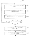
図3Bは、図3Aのタグ構文解析装置200によって、または任意の他の適切な装置によって少なくとも部分的に行うことができるタグ構文解析の例示的な方法230を表す。一実施形態において、タグ構文解析装置200のタグ構文解析部208は、方法230またはその一部分を行う。典型的に、必ずしもそうではないが、方法230の少なくとも一部分は、プロセスプラント5のフィールド環境122において行われる。 FIG. 3B represents an exemplary method 230 of tag parsing that can be performed at least partially by the tag parser 200 of FIG. 3A or by any other suitable device. In one embodiment, the tag parser 208 of the tag parser 200 performs method 230 or a portion thereof. Typically, but not necessarily, at least a portion of method 230 is performed in the field environment 122 of process plant 5.

ブロック232で、方法230は、プロセスプラント5内の物理的なフィールドデバイス102を一意的に識別するソース識別子またはタグを取得すること(232)を含む。ソース識別子またはタグのフォーマット(例えば、英数文字、ダッシュ、ドットなどの他のタイプの文字、文字の順序及び数など)は、HART、WirelessHART、も
しくはHART−IP通信プロトコル、またはいくつかの他の工業プロセスプロトコル等の、特定のプロセス通信プロトコルに従うことができる。代替的に、ソースタグは、モデル/シリアル番号、バーコード、QRコードなどの、いくつかの他の適切なフォーマットをとることができる。
At block 232, method 230 comprises obtaining a source identifier or tag that uniquely identifies the physical field device 102 within process plant 5 (232). The format of the source identifier or tag (eg, other types of characters such as alphanumeric characters, dashes, dots, order and number of characters, etc.) can be HART, WirelessHART, or the HART-IP communication protocol, or some other. Specific process communication protocols, such as industrial process protocols, can be followed. Alternatively, the source tag can take some other suitable format, such as model / serial number, barcode, QR code, etc.

フィールドデバイス102のソース識別子またはタグは、1つ以上のフィールドコミッショニングデバイス135によって、及び/またはプロセスプラント5のフィールド環境122内に配置された資産管理または他のシステム132によって取得することができる(232)。いくつかのデバイスについて、ソースタグは、フィールドデバイス102自体によって取得することができる232。一実施例において、ソースタグは、インテリジェントフィールドデバイス102a、102bのメモリから取得される。別の実施例において、ソースタグは、資産管理または他のインベントリ/設置システム132から取得される。さらに別の実施例において、ソースタグは、フィールドコミッショニングデバイス135によって、例えば、ファイルを読み出すことによって、または通信インターフェースを介してソースタグを受信することによって取得される。いくつかの状況において、フィールドデバイス102のソースタグは、フィールドコミッショニングデバイス135のインターフェースによって、例えば、ニアフィールドもしくは短距離通信インターフェース(例えば、NFC、RFIDなど)によって、またはスキャナもしくはカメラ等の光インターフェースによって取得される。例えば、フィールドコミッショニングデバイス135は、ラベル、バーコード、画像、QRコード、またはフィールドデバイス102のソースタグの他の表現をスキャンし、読み取り、または別様に光学的に取得し230、フィールドコミッショニングデバイス135は、画像処理及び/または他の適切な技術を使用することによって、フィールドデバイス102のソースタグに含まれる文字を自動的に判定する。 The source identifier or tag of the field device 102 can be obtained by one or more field commissioning devices 135 and / or by asset management or other system 132 located within the field environment 122 of process plant 5 (232). ). For some devices, the source tag can be obtained by the field device 102 itself 232. In one embodiment, the source tag is obtained from the memory of the intelligent field devices 102a, 102b. In another embodiment, the source tag is obtained from asset management or other inventory / installation system 132. In yet another embodiment, the source tag is obtained by the field commissioning device 135, for example, by reading a file or by receiving the source tag via a communication interface. In some situations, the source tag of the field device 102 is by the interface of the field commissioning device 135, eg, by a near field or short range communication interface (eg, NFC, RFID, etc.), or by an optical interface such as a scanner or camera. To be acquired. For example, the field commissioning device 135 scans, reads, or otherwise optically obtains a label, barcode, image, QR code, or other representation of the source tag of the field device 102 230, the field commissioning device 135. Automatically determines the characters contained in the source tag of the field device 102 by using image processing and / or other suitable technique.

ソースタグのフォーマット(英数文字、ダッシュ、ドットなどの他のタイプの文字、文字の順序及び数など)は、HART、WirelessHART、もしくはHART−IP通信プロトコル、またはいくつかの他の工業プロセスプロトコル等の、特定のプロセス通信プロトコルに従うことができる。代替的に、ソースタグは、モデル/シリアル番号、バーコードなどの、いくつかの他の適切なフォーマットとすることができる。フィールドデバイス102のソースタグは、フィールドデバイス102が、電力遮断、電力投入、I/O割り当て解除、I/O割り当て、切断、接続、及び/または同類のこと等の、いくつかの状態のうちのいずれかである間に取得する(232)ことができる。フィールドデバイス102の様々な状態に関する議論は、本開示の他の節において説明される。 The format of the source tag (other types of characters such as alphanumeric characters, dashes, dots, character order and number, etc.) is HART, WirelessHART, or HART-IP communication protocol, or some other industrial process protocol, etc. Can follow specific process communication protocols. Alternatively, the source tag can be in some other suitable format, such as model / serial number, barcode, etc. The source tag of the field device 102 is that the field device 102 is in several states, such as power cutoff, power on, I / O deallocation, I / O allocation, disconnection, connection, and / or the like. It can be acquired (232) while it is either. Discussions regarding the various states of field device 102 are described in other sections of this disclosure.

ブロック235で、方法230は、フィールドデバイス102を示す取得したソースタグ及び一組の構文解析ルール210に基づいて、フィールドデバイス102に対応する1つ以上のシステムタグを判定または導出することを含む。例えば、ブロック235で、フィールドデバイス102と関連付けられたデバイスタグまたは1つ以上のデバイス信号タグが判定または導出される。典型的に、システムタグの総文字数は、ソースタグの総文字数とは異なり、そのため、一組の構文解析ルール210は、トランケーション、様々な文字の削除、様々な文字の追加、ソースタグに含まれる数字の組み合わせ及び/もしくは操作、ならびに/またはソースタグの長さを修正するための別の技術を示す。故に、ブロック235で、システムタグの文字が、ソースタグの文字から導出または判定される。 At block 235, method 230 comprises determining or deriving one or more system tags corresponding to field device 102 based on the acquired source tag indicating field device 102 and a set of parsing rules 210. For example, in block 235, the device tag or one or more device signal tags associated with the field device 102 are determined or derived. Typically, the total number of characters in a system tag is different from the total number of characters in a source tag, so a set of parsing rules 210 is included in truncations, various character deletions, various character additions, and source tags. Demonstrates another technique for modifying the combination and / or manipulation of numbers and / or the length of the source tag. Therefore, in block 235, the characters of the system tag are derived or determined from the characters of the source tag.

いくつかの実施形態(図示せず)において、方法230は、デバイス102のソースタグ、デバイス102のシステムタグ、及び/または一組の構文解析規則210に基づいて、プロセスループ100と関連付けられた他のタグまたは識別子を判定または導出することを含む。一実施例において、プロセスプラント5内のプロセスループ100を識別する制御タグは、デバイス102のソースタグ、デバイス102のシステムタグ、及び/また
は一組の構文解析規則210に基づいて判定または導出される。
In some embodiments (not shown), method 230 is associated with process loop 100 based on the source tag of device 102, the system tag of device 102, and / or a set of parsing rules 210. Includes determining or deriving the tag or identifier of. In one embodiment, the control tag that identifies the process loop 100 in process plant 5 is determined or derived based on the source tag of device 102, the system tag of device 102, and / or a set of parsing rules 210. ..

いくつかの実施形態(同じく図示せず)において、方法230は、一組の構文解析規則210を定義すること、構成すること、及び/または別様には修正することを含む。例えば、構文解析規則210は、追加的なデバイスまたはデバイスタイプ102、プロセスプラント5の異なる部分、異なるプラントの場所、異なるコミッショニングデバイス135に対して、または別様には所望に応じて、定義する、構成する、及び/または修正することができる。 In some embodiments (also not shown), method 230 comprises defining, configuring, and / or otherwise modifying a set of parsing rules 210. For example, parsing rule 210 defines additional device or device type 102, different parts of process plant 5, different plant locations, different commissioning devices 135, or otherwise as desired. It can be configured and / or modified.

いずれにしても、ブロック238で、方法230は、フィールドデバイス102のシステムタグ(及び随意に、ブロック235で自動的に導出または判定した任意の他の情報)を、プロセスプラント5のフィールド環境122内に配置された1つ以上のメモリに記憶することを含む。例えば、フィールドデバイス102がインテリジェントフィールドデバイスであるときに、システムタグは、フィールドデバイス102の内部メモリに記憶することができる。システムタグは、加えて、または代替的に、I/O端子ブロック105、I/Oカード108、電子マーシャリングブロックまたは装置、CHARM110などの電子マーシャリングコンポーネントなどの、プロセスループ122内の他のコンポーネントのメモリに記憶することができる。さらに加えて、または代替的に、フィールドデバイス102のシステムタグは、1つ以上のフィールドコミッショニングツール135、及び/または資産管理または他のシステム132に記憶することができる。 In any case, at block 238, method 230 extracts the system tag of field device 102 (and optionally any other information automatically derived or determined by block 235) within the field environment 122 of process plant 5. Includes storing in one or more memories located in. For example, when the field device 102 is an intelligent field device, the system tag can be stored in the internal memory of the field device 102. The system tag, in addition or alternative, is the memory of other components in process loop 122, such as I / O terminal blocks 105, I / O cards 108, electronic marshalling blocks or devices, electronic marshalling components such as CHARM110. Can be memorized in. In addition, or alternative, the system tag of field device 102 can be stored in one or more field commissioning tools 135 and / or asset management or other system 132.

ブロック240で、方法230は、記憶したフィールドデバイス102のシステムタグを利用して、プロセスプラント5のフィールド環境122内のフィールドデバイス102において、1つ以上のコミッショニングアクティビティまたはアクションを行うことを含む。典型的に、必ずしもそうではないが、フィールドデバイス102は、1つ以上のコミッショニングアクティビティまたはアクションが行われている間、I/O割り当て解除またはI/O切断状態である(さらには、方法230のブロック232〜238のうちの任意の1つ以上の実行中に、I/O割り当て解除状態である)。記憶したシステムタグを使用してフィールドデバイス102において行うことができるコミッショニングアクティビティまたはアクション(ブロック238)の例としては、フィールドデバイス102の電力投入及び電力遮断、試験信号の注入及びそれぞれの応答の検証、フィールドデバイス102を含むアズビルトI/Oリストの少なくとも一部分の自動生成、フィールドデバイス102を含むアズビルトループ図またはマップの少なくとも一部分の自動生成などが挙げられる。 At block 240, method 230 comprises performing one or more commissioning activities or actions on field device 102 in field environment 122 of process plant 5 using the stored system tags of field device 102. Typically, but not necessarily, the field device 102 is in an I / O deallocation or I / O disconnect state (and, in addition, in method 230) while one or more commissioning activities or actions are taking place. During execution of any one or more of blocks 223 to 238, the I / O deallocation state). Examples of commissioning activities or actions (block 238) that can be performed on the field device 102 using the stored system tags include powering on and shutting down the field device 102, injecting test signals and verifying their respective responses. Examples include automatic generation of at least a portion of the as-built I / O list that includes the field device 102, automatic generation of at least a portion of the as-built loop diagram or map that includes the field device 102, and the like.

いくつかのシナリオにおいて、ブロック240は、フィールドデバイス102のシステムタグを利用して1つ以上のコミッショニングアクティビティまたはアクションを開始することを含む。例えば、フィールドデバイス102のシステムタグを使用した特定のコミッショニングアクションは、システムタグの導出(ブロック235)の完了時またはシステムタグの記憶(ブロック238)の完了時に自動的に開始される。いくつかのシナリオにおいて、ブロック238は、加えて、または代替的に、例えばフィールドデバイス102及び別のデバイスの両方が関係する別のコミッショニングアクションにおいて使用するために、フィールドデバイス102のシステムタグを、プロセスプラント5のフィールド環境122内に配置された別のデバイスに提供することを含む。例えば、フィールドデバイス102のシステムタグは、それぞれのCHARM110に提供することができ、フィールドデバイス102及びCHARM110の両方を含む制御ループ100の一部分は、フィールドデバイス102のシステムタグを使用してコミッショニングすることができる。 In some scenarios, block 240 comprises initiating one or more commissioning activities or actions utilizing the system tag of field device 102. For example, a particular commissioning action using the system tag of the field device 102 is automatically initiated upon completion of system tag derivation (block 235) or system tag storage (block 238). In some scenarios, block 238 processes the system tag of field device 102, in addition or alternatively, for use in another commissioning action involving both field device 102 and another device, for example. Includes providing to another device located within the field environment 122 of plant 5. For example, the system tag of the field device 102 can be provided to each CHARM 110, and a part of the control loop 100 including both the field device 102 and the CHARM 110 can be commissioned using the system tag of the field device 102. can.

入力/出力(I/O)割り当て状態 Input / output (I / O) allocation status

スマートコミッショニングの別の鍵となる態様は、プロセスプラント5のフィールド環境122における、フィールドデバイス102などのデバイスのI/O割り当て状態の可用性、及びそのI/O割り当て状態に基づいてデバイスを少なくとも部分的に構成する能力である。全般的に言えば、デバイス102のI/O割り当て状態は、デバイスが、特定のI/Oカードに、及びいくつかの事例では特定のI/Oチャネルに割り当てられているかどうか、または割り当てられるかどうかを示す。例えば、デバイス102は、特定の物理的I/Oアドレス及び/または特定のI/Oチャネルがフィールド環境122内のデバイス102にまだ指定されていないときに、I/O割り当て解除状態であるとみなされ、すなわち、特定のデバイス102の特定の物理的I/Oアドレス/チャネルへのマッピングは、フィールド環境122において利用できない。一方で、デバイス102は、特定の物理的I/Oアドレス(及び随意に、例えば有線デバイスの場合、特定のI/Oチャネル)がフィールド環境122内のデバイス102に指定されているときに、I/O割り当て状態であるとみなされ、該指定は、フィールド環境122内に設置された1つ以上のコンポーネントに記憶され、それによって、デバイス102と指定された特定のI/Oカード及び/または特定のI/Oチャンネルとの間のマッピングを利用できるようにする。フィールド環境122内のデバイスのI/O割り当て状態の可用性、及び割り当て解除されたデバイスを少なくとも部分的に構成する能力によって、従来のフィールドコミッショニング中に現在必要とされるような、特定のI/Oカード及び特定のI/Oチャンネルへの指定に対する待機を必要とすることなく、様々なデバイスがI/O割り当て解除状態である間に、様々なコミッショニングアクション及び/またはアクティビティを開始すること、行うこと、さらには完了することができる(122)。 Another key aspect of smart commissioning is the availability of I / O allocation status of devices such as field device 102 in the field environment 122 of process plant 5, and at least partial device based on that I / O allocation status. Is the ability to compose. Generally speaking, the I / O allocation state of device 102 is whether or whether the device is assigned to a particular I / O card and, in some cases, a particular I / O channel. I will show you. For example, device 102 is considered to be in an I / O deallocation state when a particular physical I / O address and / or particular I / O channel has not yet been designated for device 102 in field environment 122. That is, the mapping of a particular device 102 to a particular physical I / O address / channel is not available in the field environment 122. On the other hand, the device 102 is I / O when a particular physical I / O address (and optionally, for example, in the case of a wired device, a particular I / O channel) is designated for the device 102 in the field environment 122. Considered to be in the / O allocation state, the designation is stored in one or more components installed within the field environment 122, thereby specifying the specific I / O card and / or specific designated as device 102. Make the mapping between I / O channels available. The availability of the I / O allocation state of the devices in the field environment 122, and the ability to at least partially configure the unassigned devices, make certain I / O as currently required during traditional field commissioning. Initiating and performing various commissioning actions and / or activities while the various devices are in the I / O deallocation state, without the need to wait for a card and designation to a particular I / O channel. , And even complete (122).

例示される図2A〜2Cを参照すると、フィールドデバイス102b、102dのI/O割り当て状態は、フィールドデバイス102b、102dが、そのそれぞれのI/Oカード108に、及び/またはカード108のそのそれぞれのI/Oチャンネルに割り当てられた可動化を示す。電子的にマーシャリングされるフィールドデバイス102a、102cについて、フィールドデバイス102a、102cのI/O割り当て状態は、フィールドデバイス102a、102cが、そのそれぞれのCIOC145、CHARM端子ブロック150、及び/またはCIOCチャネルに割り当てられたかどうかを示す。しかし、一般に、本明細書での読み取りを容易にするために、デバイスの「I/O割り当て状態」、及び「I/O割り当て」、「I/O割り当て解除」などの関連する用語は、デバイスが、任意のタイプのI/Oカード及び/またはI/Oチャネル全体に指定されているかどうか、例えば、任意のレガシーまたはスマートI/Oカード、CIOC、WIOC(無線I/Oカード)、安全情報システム論理ソルバー(例えば、単体、複合、スマート論理ソルバー、CSLS(CHARMスマート論理ソルバー)など)、またはプロセス制御及び/もしくは安全情報システムにおいて使用して、デバイスに対応するI/O機能を行う任意の他の既知のタイプのカード/チャネルに割り当てられているかどうかを示す。そのため、読み取りを容易にするために、「I/Oカード」、「I/Oチャネル」、及び「I/Oノード」という用語は、一般に、任意のタイプのI/Oカード、I/Oチャネル、及びI/Oノードを指すために本明細書で使用される。 Referring to FIGS. 2A-2C, the I / O allocation state of the field devices 102b, 102d is such that the field devices 102b, 102d are assigned to their respective I / O cards 108 and / or their respective cards 108. Shows the mobilization assigned to the I / O channel. For the electronically marshalled field devices 102a, 102c, the I / O allocation status of the field devices 102a, 102c is such that the field devices 102a, 102c are assigned to their respective CIOC145, CHARM terminal block 150, and / or CIOC channel. Indicates whether or not it was done. However, in general, for ease of reading herein, the device's "I / O allocation status" and related terms such as "I / O allocation" and "I / O deallocation" are used for devices. Is specified for any type of I / O card and / or for the entire I / O channel, eg, any legacy or smart I / O card, CIOC, WIOC (wireless I / O card), safety information. Any system logic solver (eg, standalone, composite, smart logic solver, CSLS (CHARM smart logic solver), etc.), or used in process control and / or safety information systems to perform device-aware I / O functionality. Indicates whether it is assigned to another known type of card / channel. Therefore, for ease of reading, the terms "I / O card", "I / O channel", and "I / O node" generally refer to any type of I / O card, I / O channel. , And as used herein to refer to an I / O node.

デバイスコンテナまたはプレースホルダーは、フィールド環境122内のデバイス102のI/O割り当て状態の可用性、ならびにその特定のI/O接続がバックエンド環境125によってまだ定義または提供されていない間に、フィールド環境122内のデバイス102を少なくとも部分的に構成し、コミッショニングする能力を可能にする。全般的に言えば、デバイスコンテナまたはフィールドデバイス102のためのプレースホルダーは、下で説明するように、デバイス102のI/O抽象化構成を保持または記憶する。 The device container or placeholder is the availability of the I / O allocation state of the device 102 in the field environment 122, as well as the field environment 122 while that particular I / O connection has not yet been defined or provided by the backend environment 125. The device 102 within is at least partially configured to allow the ability to commission. Generally speaking, a placeholder for a device container or field device 102 retains or stores the I / O abstraction configuration of device 102, as described below.

デバイスコンテナまたはプレースホルダーは、例えば、フィールド環境122において
、構成することができる構成可能なオブジェクトとして(または別の適切な定義記憶表現として)、それぞれのデバイスのためのコンテナまたはプレースホルダーの特定のインスタンスに実装される。デバイスコンテナまたはプレースホルダーは、フィールド環境122において、資産管理もしくは他のインベントリもしくは設置システム132によって、及び/またはフィールドコミッショニングデバイス135によって提供することができる。特定のスマートフィールドデバイス102c、102bについて、スマートフィールドデバイス102a、102bに対応するデバイスプレースホルダーまたはコンテナのそれぞれのインスタンスは、例えば、デバイス102がフィールド環境122に設置される前に、またはデバイス102がフィールド環境102内に設置された後に、デバイスのメモリに推測的に、またはデバイスのメモリへの転送により記憶することができる。
A device container or placeholder is, for example, in a field environment 122, as a configurable object that can be configured (or as another suitable definitional storage representation), a particular instance of a container or placeholder for each device. Is implemented in. Device containers or placeholders can be provided in field environment 122 by asset management or other inventory or installation system 132 and / or by field commissioning device 135. For a particular smart field device 102c, 102b, each instance of the device placeholder or container corresponding to the smart field device 102a, 102b may be, for example, before the device 102 is placed in the field environment 122, or when the device 102 is in the field. After being installed in the environment 102, it can be stored in the memory of the device speculatively or by transfer to the memory of the device.

デバイスコンテナまたはプレースホルダーオブジェクトは、デバイスのI/O割り当て状態を記憶するためのフィールドまたはプロパティを含む。デバイスコンテナまたはプレースホルダーオブジェクトは、デバイスの物理的なI/Oレイアウトが定義される前に様々なデバイス構成パラメータ値を記憶するための、追加的なフィールドまたはプロパティを含む。すなわち、I/O割り当て解除状態のデバイス102について、デバイス102の少なくとも部分的な、または抽象化構成を定義し、抽象化I/Oタイプ情報と共に、その対応するデバイスコンテナまたはプレースホルダーに記憶することができ、よって、デバイスの正確なI/O構成に関する知識を伴わずに、さらにはいくつかの事例において、デバイスの対応する物理的I/Oノードの存在さらには作成を伴わずに、デバイス102を少なくとも部分的に構成し、コミッショニングすることができる。さらに、デバイスコンテナまたはプレースホルダーオブジェクトは、多数のタイプのデバイスについて共通であり、また、対応する物理的デバイスの特定のタイプのI/Oとは独立である。全般的に言えば、デバイスコンテナまたはプレースホルダーオブジェクトの様々なプロパティは、公開プロパティとすることができ、及び/またはデバイスコンテナ/プレースホルダーオブジェクトの様々なプロパティは、隠されたプロパティとすることができる。 A device container or placeholder object contains a field or property for storing the device's I / O allocation status. A device container or placeholder object contains additional fields or properties for storing various device configuration parameter values before the physical I / O layout of the device is defined. That is, for the device 102 in the I / O deallocation state, at least a partial or abstract configuration of the device 102 is defined and stored together with the abstract I / O type information in its corresponding device container or placeholder. Thus, the device 102, without knowledge of the exact I / O configuration of the device, and in some cases, without the existence or creation of the corresponding physical I / O node of the device. Can be constructed and commissioned at least partially. In addition, device containers or placeholder objects are common to many types of devices and are independent of the specific type of I / O of the corresponding physical device. Generally speaking, various properties of the device container or placeholder object can be public properties, and / or various properties of the device container / placeholder object can be hidden properties. ..

図4Aは、プロセスプラント5のフィールド環境122において利用される例示的なデバイスコンテナまたはプレースホルダーオブジェクトテンプレート300を表す。デバイスコンテナまたはプレースホルダーオブジェクト300を使用すると、ユーザは、デバイスプレースホルダーオブジェクト300のインスタンスを作成して、I/O抽象化情報を使用してデバイス102をプロセス制御システム5に対して定義することができ、よって、例えば、デバイス102が関係する様々なコミッショニングアクションは、デバイス102がI/O割り当て解除状態である間に(すなわち、デバイス102が特定の物理的I/Oカード、I/Oチャネル、及び/またはI/Oノードに割り当てられる前に)行うことができる。例えば、ユーザは、デバイス102に対応する一組の一般プロパティ302の所望の値、例えば、名前、説明、ケーブリングID、典型的な配線図などを入力することによって、デバイス102のデバイスコンテナまたはプレースホルダーオブジェクト300のインスタンスを定義することを開始することができる。特にHARTデバイスについて、一般プロパティ302は、加えて、いくつか例を挙げれば、HARTの説明、HARTデバイスの定義、HARTロングタグ、名前付け参照タイプ、及び名前付け参照サブタイプなどの、HART固有のプロパティを含む。非HARTである他のタイプのデバイス(図示せず)について、デバイスのタイプに対応する他のプロパティは、オブジェクト300に含むことができる。一実施形態において、デバイスコンテナまたはプレースホルダーオブジェクト300は、例えば別の一般プロパティ302を公開することによって、または異なるタイプのデバイスプレースホルダーオブジェクト300をそれぞれベーシックプロセス制御システム(BPCS)または及び安全計装システム(SIS)デバイスに対応させることによって、オブジェクト300が、BPCSデバイスデバイスに対応するか、またはSISデバイスに対応するかを示す。 FIG. 4A represents an exemplary device container or placeholder object template 300 used in the field environment 122 of process plant 5. Using the device container or placeholder object 300, the user can create an instance of the device placeholder object 300 and use the I / O abstraction information to define the device 102 for the process control system 5. Thus, for example, various commissioning actions involving device 102 can be performed while device 102 is in the I / O deassignment state (ie, device 102 is a particular physical I / O card, I / O channel, etc. And / or can be done (before being assigned to an I / O node). For example, the user may enter a device container or place for device 102 by entering the desired values for a set of general properties 302 corresponding to device 102, such as name, description, cabling ID, typical wiring diagram, and so on. You can start defining an instance of the holder object 300. Especially for HART devices, the general property 302 is also HART-specific, such as HART description, HART device definition, HART long tag, naming reference type, and naming reference subtype, to name a few. Includes properties. For other types of non-HART devices (not shown), other properties corresponding to the device type can be included in object 300. In one embodiment, the device container or placeholder object 300, for example by exposing another general property 302, or a different type of device placeholder object 300, respectively, is a basic process control system (BPCS) or a safety instrumented system. By making it compatible with the (SIS) device, it indicates whether the object 300 corresponds to the BPCS device device or the SIS device.

デバイスプレースホルダーオブジェクト300はまた、接続経路プロパティ305も含み、その値は、対応するデバイスが、I/O割り当て状態であるか、I/O割り当て解除状態であるかを示す。典型的に、必ずしもそうではないが、ユーザが対応するデバイスを構成することを望むデバイスプレースホルダーオブジェクト300のインスタンスの初期化に応じて、インスタンスの接続経路プロパティ305のデフォルト値が「I/O割り当て解除」に設定され、明示的なI/Oハードウェア接続が定義された後に、インスタンスの接続経路プロパティ305が「I/O割り当て」に変更される。いずれにしても、デバイス102の接続経路プロパティ302が「I/O割り当て解除」に設定されていることに基づいて、オブジェクト300の1つ以上の他のプロパティまたはフィールド(例えば、参照番号308〜338)は、ユーザがそれぞれの値をそこに入力してインスタンスをさらに定義または構成するように公開される。プロパティ308〜338のうちの少なくともいくつかは、「I/O抽象化」プロパティであり、すなわち、その値が、対象のデバイスの能力、特徴、及び/または挙動を示し、その値は、対象のデバイスに対する実際の指定された物理的I/O接続に基づいていない(また、該物理的I/O接続に関する知識を必要としない)。 The device placeholder object 300 also includes a connection path property 305 whose value indicates whether the corresponding device is in the I / O allocated state or the I / O deallocated state. Typically, but not always, the default value of the instance's connection path property 305 is "I / O allocation" depending on the initialization of the instance of the device placeholder object 300 that the user wants to configure the corresponding device. After being set to "Release" and an explicit I / O hardware connection is defined, the instance's connection path property 305 is changed to "I / O Assignment". In any case, one or more other properties or fields of object 300 (eg, reference numbers 308-338) based on the connection path property 302 of device 102 being set to "I / O deallocation". ) Is exposed so that the user can enter their respective values there to further define or configure the instance. At least some of the properties 308-338 are "I / O abstraction" properties, i.e. their values indicate the capabilities, characteristics, and / or behavior of the device of interest, and the values of which are of interest. It is not based on the actual specified physical I / O connection to the device (and does not require knowledge of that physical I / O connection).

例えば、デバイスプレースホルダーオブジェクト300は、一組のI/O抽象化デバイス定義プロパティ308を含み、それを介して、ユーザは、I/O抽象化を使用して対象のデバイスを定義または構成することができる。I/O割り当て解除状態のデバイス102(例えば、接続経路プロパティ305によって示される)について、I/O抽象化デバイス定義308は、I/O抽象化インターフェースタイププロパティ310を含み、その値は、I/Oインターフェースのタイプまたはカテゴリを示すように定義または選択することができ、該I/Oインターフェースを介して、物理的デバイス102を物理的に接続することができる。I/O抽象化インターフェースタイププロパティ310の可能な値としては、例えば、「従来」(例えば、ダム(dumb)、非スマート、非HART、従来の、及び/またはレガシーデバイスの場合)、「HART」、「WirelessHART」、「SIS従来」、「SIS HART」などが挙げられる。 For example, the device placeholder object 300 includes a set of I / O abstraction device definition properties 308 through which the user can define or configure the device of interest using the I / O abstraction. Can be done. For device 102 in the I / O deallocation state (eg, indicated by connection path property 305), the I / O abstraction device definition 308 includes an I / O abstraction interface type property 310, the value of which is the I / O abstraction interface type property 310. It can be defined or selected to indicate the type or category of the O interface, and the physical device 102 can be physically connected through the I / O interface. Possible values for the I / O abstraction interface type property 310 include, for example, "conventional" (eg, for dam, non-smart, non-HART, conventional, and / or legacy devices), "HART". , "Wireless HART", "SIS conventional", "SIS HART" and the like.

オブジェクト300内のI/O抽象化インターフェースタイプ310を定義した後に、定義/ポピュレートされたI/O抽象化インターフェースタイプ310に対応する追加的なプロパティを公開して、ユーザがI/O抽象化デバイス定義308をさらに精緻化することを可能にする。例えば、「従来」、「SIS従来」、または「HART」の定義されたI/O抽象化インターフェースタイプ310について、I/O抽象化デバイスタイププロパティ312が公開される。全般的に言えば、I/O抽象化デバイスタイププロパティ312は、デバイス102のタイプまたはカテゴリを示し、それによって、デバイス102のI/O抽象化デバイス定義308をさらに精緻化する。可能なI/O抽象化デバイスタイプ312の例としては、電流入力、電流出力、離散入力、離散出力、パルス入力、連続パルス出力、熱電対入力、ミリボルト入力、RTD(抵抗温度検出器)入力、熱電対入力、電圧入力、24VDC電源、HARTアナログ入力、HART2状態DVC出力、WirelessHARTなどが挙げられる。 After defining the I / O abstraction interface type 310 in object 300, the user exposes the additional properties corresponding to the defined / popular I / O abstraction interface type 310 so that the user can use the I / O abstraction device. Allows the definition 308 to be further refined. For example, for an I / O abstraction interface type 310 defined as "conventional," "SIS conventional," or "HART," the I / O abstraction device type property 312 is exposed. Generally speaking, the I / O abstraction device type property 312 indicates the type or category of the device 102, thereby further refining the I / O abstraction device definition 308 of the device 102. Examples of possible I / O abstraction device types 312 are current input, current output, discrete input, discrete output, pulse input, continuous pulse output, thermocouple input, millivolt input, RTD (resistance temperature detector) input, Examples thereof include thermocouple input, voltage input, 24VDC power supply, HART analog input, HART2 state DVC output, and WirelessHART.

しかし、いくつかのI/Oインターフェースデバイスタイプ310は、いかなるI/O抽象化デバイスタイプ312も公開しない結果になり得る(例えば、様々なプロパティが隠されたままであり得る)が、一方で、他のI/Oインターフェースデバイスタイプ310は、1つ、2つ、またはそれ以上のI/O抽象化デバイスタイプ312を公開する結果になり得る。特定のI/O抽象化インターフェースタイプ310の1つ以上のI/O抽象化デバイスタイプ312(該当する場合)へのマッピングまたは関連付けは、推測的に定義することができ、いくつかの事例では、修正することができる。 However, some I / O interface device types 310 may result in not exposing any I / O abstraction device type 312 (eg, various properties may remain hidden), while others. I / O interface device type 310 can result in the exposure of one, two, or more I / O abstraction device types 312. The mapping or association of a particular I / O abstraction interface type 310 to one or more I / O abstraction device types 312 (if applicable) can be speculatively defined, and in some cases, in some cases. It can be fixed.

オブジェクト300内のI/O抽象化デバイスタイプ312を定義した後に、いくつか
のI/O抽象化デバイスタイプ312について、1つ以上のI/O抽象化デバイス特徴プロパティ315を公開して、I/O抽象化デバイス定義308をさらに精緻化することができる。例えば、I/O抽象化デバイスタイプ312が「電流入力」と定義された場合は、対応する記述値、例えば「0〜20mA」、「4〜20mA」などを記憶するために、対応するI/O抽象化デバイス特徴315、例えば「デバイスサブタイプ」が公開される。別の例において、I/O抽象化デバイスタイプ312があるタイプのHARTデバイス(例えば、HARTアナログ入力、HART2状態DVC出力、WirelessHARTなど)であった場合は、それぞれのHART情報を定義308に記憶することができるように、デバイス102の「HART製造業者」、「HARTモデル」、及び「HARTリビジョン」などの、対応するI/O抽象化デバイス特徴315が公開される。いくつかのI/O抽象化デバイスタイプ312は、いかなるI/O抽象化デバイス特徴315も公開しない結果になり得るが、一方で、他のI/O抽象化デバイスタイプ312は、1つ、2つ、またはそれ以上のI/O抽象化デバイス特徴315を公開する結果になり得る。特定のI/O抽象化デバイスタイプ312の1つ以上のI/O抽象化デバイス特徴315(該当する場合)へのマッピングまたは関連付けは、推測的に定義することができ、いくつかの事例では、修正することができる。
After defining the I / O abstraction device type 312 in object 300, expose one or more I / O abstraction device feature properties 315 for some I / O abstraction device type 312 to expose the I / O abstraction device type 312. The O abstraction device definition 308 can be further refined. For example, if the I / O abstraction device type 312 is defined as "current input", the corresponding I / O to store the corresponding descriptive values, such as "0-20mA", "4-20mA", etc. O abstraction device features 315, such as "device subtypes", are published. In another example, if the I / O abstraction device type 312 is a type of HART device (eg, HART analog input, HART2 state DVC output, WilllessHART, etc.), each HART information is stored in definition 308. Corresponding I / O abstraction device features 315, such as the "HART manufacturer", "HART model", and "HART revision" of the device 102, are exposed so that they can. Some I / O abstraction device types 312 may result in not exposing any I / O abstraction device features 315, while other I / O abstraction device types 312 have one, two. It can result in exposing one or more I / O abstraction device features 315. The mapping or association of a particular I / O abstraction device type 312 to one or more I / O abstraction device features 315 (if applicable) can be speculatively defined, and in some cases, in some cases. It can be fixed.

I/O抽象化デバイス定義308はまた、一組のI/O抽象化I/Oインターフェース構成プロパティ318も含み、それを介して、デバイス102のI/Oインターフェース構成が定義される。I/O抽象化I/Oインターフェース構成プロパティ318の可能なタイプ及びカテゴリ(及びいくつかの事例では、固有の値)は、少なくとも部分的に、定義されたI/Oデバイス定義308に基づく。図4Aに示されるように、I/O抽象化I/Oインターフェース構成プロパティ318は、公開された様々なI/O構成パラメータプロパティ320及び/またはI/Oチャネルパラメータ322を含むことができる。 The I / O abstraction device definition 308 also includes a set of I / O abstraction I / O interface configuration properties 318 through which the I / O interface configuration of the device 102 is defined. The possible types and categories (and, in some cases, unique values) of the I / O abstraction I / O interface configuration property 318 are based, at least in part, on the defined I / O device definition 308. As shown in FIG. 4A, the I / O abstraction I / O interface configuration property 318 can include various exposed I / O configuration parameter properties 320 and / or I / O channel parameters 322.

例えば、構成または定義されたデバイス102のI/O抽象化デバイス定義308の定義されたプロパティ値310〜315に基づいて、構成または定義されたデバイス102と互換性があるI/Oハードウェア(例えば、CHARM、I/Oカードなど)のタイプが判定される。様々なデバイス定義値308と様々なタイプのI/Oハードウェアとの互換性は、推測的に定義することができ、また、いくつかの事例では、修正することができる。一実施形態において、デバイス定義値308とI/Oハードウェアのタイプとの間の互換性は、互換性マトリックスで、または他の適切なフォーマットで記憶される。加えて、デバイス102のI/O抽象化デバイス定義308と互換性がある、構成または定義された各タイプのI/Oハードウェアが、次に、一組のI/O抽象化I/O構成パラメータプロパティ320のそれぞれに対応する。故に、デバイス102についてその定義をさらに精緻化するために、一組のI/O抽象化I/O構成パラメータプロパティ320のそれぞれが、I/O抽象化I/Oインターフェース構成318に公開される。いくつかのアナログ、有線、または従来タイプのI/Oハードウェアについて、それぞれのI/O抽象化I/O構成パラメータプロパティ320は、デバイス102のI/O抽象化I/Oインターフェース構成318をさらに精緻化するために公開される、1つ以上のチャネルパラメータプロパティ322を含む。アナログ、有線、及び/または従来タイプではないI/Oハードウェア(例えば、デジタルまたはスマートI/Oハードウェアタイプ)について、チャネルパラメータプロパティ322は、排除される、例えば、公開されないか、または隠される。 For example, I / O abstraction of the configured or defined device 102 I / O hardware compatible with the configured or defined device 102 (eg, based on the defined property values 310-315 of the device definition 308). , CHARM, I / O card, etc.) type is determined. Compatibility between different device definition values 308 and different types of I / O hardware can be speculatively defined and, in some cases, modified. In one embodiment, the compatibility between the device definition value 308 and the type of I / O hardware is stored in the compatibility matrix or in any other suitable format. In addition, each type of I / O hardware configured or defined that is compatible with the I / O abstraction device definition 308 of device 102 is then a set of I / O abstraction I / O configurations. Corresponds to each of the parameter properties 320. Therefore, in order to further refine the definition of the device 102, each of the set of I / O abstraction I / O configuration parameter properties 320 is exposed in the I / O abstraction I / O interface configuration 318. For some analog, wired, or conventional type I / O hardware, each I / O abstraction I / O configuration parameter property 320 further adds to the I / O abstraction I / O interface configuration 318 of device 102. Includes one or more channel parameter properties 322 that are exposed for refinement. For analog, wired, and / or non-traditional I / O hardware (eg, digital or smart I / O hardware types), the channel parameter property 322 is excluded, eg, not exposed or hidden. ..

例示のために、デバイス102のI/O抽象化デバイス定義308が従来の電流入力4〜20mAのデバイスとして構成されると想定する。そのようなI/O抽象化デバイス定義308は、(例えば、互換性マッピングまたは関連付けに基づいて判定したときに)2つの特定のタイプのI/Oハードウェア、例えば、AI(アナログ入力)4〜20mA HART CHARM及びIS(本質安全)AI 4〜20mA HART CHARM
と互換性がある。故に、構成及び/または定義するために、AI(アナログ入力)4〜20mA HART CHARM及びIS AI 4〜20mA HART CHARMの両方のそれぞれ一組のI/O抽象化I/O構成パラメータプロパティ320が、I/O抽象化I/Oインターフェース構成318に公開される。両方の互換性のあるタイプのI/Oハードウェアが従来のタイプのI/Oハードウェアであるので、互換性のあるタイプ(例えば、アンチエイリアシングフィルタ、アンダーレンジリミット、オーバーレンジリミット、NAMURリミット検出など)の各々に対応するそれぞれのチャネルプロパティ322が、デバイス102のI/O抽象化I/Oインターフェース構成318のさらなる精緻化のために公開される。
For illustration purposes, it is assumed that the I / O abstraction device definition 308 of device 102 is configured as a device with a conventional current input of 4 to 20 mA. Such an I / O abstraction device definition 308 includes two specific types of I / O hardware (eg, when determined based on compatibility mapping or association), eg, AI (Analog Input) 4 to. 20mA HART CHARM and IS (intrinsic safety) AI 4-20mA HART CHARM
Compatible with. Therefore, to configure and / or define, each set of I / O abstraction I / O configuration parameter properties 320 for both AI (analog input) 4-20 mA HART CHARM and IS AI 4-20 mA HART CHARM Published in I / O Abstraction I / O Interface Configuration 318. Since both compatible types of I / O hardware are traditional types of I / O hardware, compatible types (eg, anti-aliasing filters, underrange limits, overrange limits, NAMUR limit detection) Each channel property 322 corresponding to each of the devices 102 is exposed for further refinement of the I / O abstraction I / O interface configuration 318 of the device 102.

1つ以上の特定のチャンネルプロパティ322の、1つ以上の特定のタイプのI/O抽象化I/O構成パラメータプロパティ320への、及び/または1つ以上の特定のタイプのI/Oハードウェア(したがって、それぞれの特定のI/O抽象化デバイス定義308)へのマッピングまたは関連付けは、推測的に定義することができ、また、修正することができる。同様に、アナログ、有線、及び/または従来のタイプではないI/Oハードウェア(例えば、デジタルまたはスマートI/Oハードウェアタイプ)について、1つ以上の特定のI/O抽象化I/Oインターフェース構成プロパティ318の、1つ以上の特定のタイプのI/Oハードウェア(したがって、特定のI/O抽象化デバイス定義308)へのマッピングまたは関連付けは、推測的に定義することができ、また、修正することができる。 One or more specific channel properties 322 to one or more specific types of I / O abstraction I / O configuration parameter properties 320 and / or one or more specific types of I / O hardware (Therefore, the mapping or association to each particular I / O abstraction device definition 308) can be speculatively defined and modified. Similarly, for analog, wired, and / or non-traditional types of I / O hardware (eg, digital or smart I / O hardware types), one or more specific I / O abstraction I / O interfaces. The mapping or association of the configuration property 318 to one or more specific types of I / O hardware (and thus the specific I / O abstraction device definition 308) can be speculatively defined and also defined. It can be fixed.

I/O抽象化デバイス定義308に含むことができる他のプロパティとしては、例示的なHARTデバイス警告プロパティ328、例示的なHARTデバイスアラームプロパティ330、自動ループ試験構成プロパティ332、及び/または他のI/O抽象化プロパティ335などの、デバイスプロトコル固有のプロパティが挙げられる。当然ながら、ファンデーションフィールドバスプロトコルデバイス、CANデバイス、Profibusデバイスなどの他のデバイスプロトコルは、そうしたプロトコルに従って構成することができる他の予め定義されたプロパティを有することができる。図4Aに例示されるように、I/O抽象化デバイスタイプ312がHARTまたはWirelessHARTに設定されたときに定義するために、例示的なHARTデバイス警告プロパティ328及びHARTデバイスアラームプロパティ330が、公開される。全般的に言えば、HARTデバイス警告プロパティ328及びHARTデバイスアラームプロパティ330は、どのタイプのアラーム(該当する場合)を様々なタイプの警告に対して起動させるか、及び該アラームのそれぞれの挙動を定義する。アラームのタイプの例としては、勧告、障害、保守、通信切断、アラームなし、などが挙げられる。警告のタイプの例としては、例えば、フィールドデバイスの故障、構成の変更、プライマリ変数の限度超、CPU EEPROMの書き込み障害、及び/またはHARTデバイスに関する他の警告が挙げられる。自動ループ試験構成プロパティ332は、対象のデバイスが関係する自動ループ試験の、及びその様々な態様の値を定義する。例えば、自動ループ試験について生成される試験信号のタイプ及びレベルを示す値は、自動ループ試験構成プロパティ332に記憶することができる。当然ながら、I/O抽象化デバイス定義308の任意の他の所望のI/O抽象化プロパティ335を、定義または構成のために、追加的または代替的に公開することができる。加えて、(I/O抽象化となる、またはならない場合がある)オブジェクト300の任意の他のプロパティ338を、定義または構成のために、追加的または代替的に公開することができる。全般的に言えば、デバイス102について、そのデバイスコンテナオブジェクト300のインスタンスに記憶した特定の値302〜338は、少なくとも部分的にI/O抽象化した様態で特定のデバイス102を定義または構成する。 Other properties that can be included in the I / O abstraction device definition 308 include the exemplary HART device warning property 328, the exemplary HART device alarm property 330, the automatic loop test configuration property 332, and / or other I. Examples include device protocol-specific properties such as the / O abstraction property 335. Of course, other device protocols such as foundation fieldbus protocol devices, CAN devices, and Profibus devices can have other predefined properties that can be configured according to such protocols. As illustrated in FIG. 4A, exemplary HART device warning property 328 and HART device alarm property 330 are exposed to define when the I / O abstraction device type 312 is set to HART or WilllessHART. NS. Generally speaking, the HART device warning property 328 and the HART device alarm property 330 define which type of alarm (if applicable) is triggered for different types of warnings, and the behavior of each of those alarms. do. Examples of alarm types include recommendations, failures, maintenance, loss of communication, no alarm, and so on. Examples of warning types include, for example, field device failures, configuration changes, primary variable limits, CPU EEPROM write failures, and / or other warnings about HART devices. The automatic loop test configuration property 332 defines values for the automatic loop test in which the device of interest is involved, and various aspects thereof. For example, a value indicating the type and level of the test signal generated for the automatic loop test can be stored in the automatic loop test configuration property 332. Of course, any other desired I / O abstraction property 335 of the I / O abstraction device definition 308 can be exposed additionally or alternative for definition or configuration. In addition, any other property 338 of Object 300 (which may or may not be an I / O abstraction) may be exposed additionally or alternatively for definition or configuration. Generally speaking, for device 102, the specific values 302 to 338 stored in the instance of the device container object 300 define or configure the specific device 102, at least in a partially I / O abstracted manner.

一般に、従来デバイスは、その対応するI/O抽象化I/Oインターフェースタイプ310、I/O抽象化デバイスタイプ312、デバイスサブタイプ特徴315プロパティが
提供されたとき、選択されたとき、または別様に定義されたときに、I/O抽象化情報を使用して、十分に定義または構成されたものとみなされ、HARTデバイスは、そのI/O抽象化I/Oインターフェースタイプ310、I/O抽象化デバイスタイプ312、ならびにI/O抽象化デバイス特徴315の製造業者、モデル、及びリビジョンプロパティが提供されたとき、選択されたとき、または別様に定義されたときに、I/O抽象化情報を使用して、十分に定義または構成されたものとみなされる。
In general, conventional devices have their corresponding I / O abstraction I / O interface type 310, I / O abstraction device type 312, device subtype feature 315 properties provided, selected, or otherwise. When defined in, the HART device is considered to be well defined or configured using the I / O abstraction information, and the HART device has its I / O abstraction I / O interface type 310, I / O. I / O abstraction when the manufacturer, model, and revision properties of the abstraction device type 312, as well as the I / O abstraction device feature 315, are provided, selected, or otherwise defined. The information is considered to be well defined or structured.

さらに、いくつかの実現形態において、フィールドデバイス102のデバイスプレースホルダー300のインスタンスに保持または記憶したプロパティの値の少なくともいくつかは、メタデータとして記憶される。例えば、プロパティ値305〜308のうちの任意の1つ以上、及び1つ以上の一般プロパティ値302を、メタデータとして保持または記憶することができる。 Further, in some embodiments, at least some of the property values held or stored in the device placeholder 300 instance of the field device 102 are stored as metadata. For example, any one or more of the property values 305 to 308 and one or more general property values 302 can be retained or stored as metadata.

したがって、デバイスコンテナまたはプレースホルダーオブジェクト300は、デバイスの特定のI/Oカード、I/Oチャンネル、及び/またはI/Oノードがデバイス102に指定される前に、特定のデバイス102及びフィールド環境122を、I/O抽象化様態で構成することを可能にする。具体的には、デバイスプレースホルダーオブジェクト300は、フィールドデバイス102の特定の識別情報(例えば、デバイス102がHARTデバイスである場合の、その名前、そのロングタグ、そのHARTデバイス定義など)、及びデバイス102の様々な属性(参照番号308〜335、随意に、302及び338において選択されたプロパティ)を構成することを可能にし、これらのうちの少なくともいくつかは、I/O抽象化される。フィールドデバイス102の属性は、アンダーレンジ及び/またはオーバーレンジ限度のアラーム、警告、検出などの様々な条件が起こったときのデバイス102の記述属性ならびにデバイス102の挙動属性または挙動、ならびに他の挙動を含む。フィールドデバイス102の属性のうちの少なくともいくつかは、明示的な識別情報(例えば、タイプ310、312、318など)の代わりに、デバイス102に対応するそれぞれのカテゴリ、タイプ、または特徴を示し、したがって「I/O抽象化」である。さらに、デバイス102のデバイスプレースホルダーオブジェクトのインスタンスに保持または記憶したプロパティ値302〜338のうちの少なくともいくつかは、デバイス102を特定のI/Oカード、特定のI/Oチャネル、及び/または特定のI/Oノードに指定する時点で、または指定した後に、例えば、下の節で説明されるように、デバイスの接続経路プロパティ305が変更されて、デバイス102がI/O割り当て状態であることを示した後に、プロセス制御システム5を通して保存または実行される。 Thus, the device container or placeholder object 300 may have a particular device 102 and field environment 122 before a particular I / O card, I / O channel, and / or I / O node of the device is designated for device 102. Can be constructed in an I / O abstraction mode. Specifically, the device placeholder object 300 contains specific identification information of the field device 102 (for example, its name when the device 102 is a HART device, its long tag, its HART device definition, etc.), and the device 102. It is possible to configure various attributes of (reference numbers 308-335, optionally selected properties in 302 and 338), at least some of which are I / O abstracted. The attributes of the field device 102 include the description attributes of the device 102 and the behavior attributes or behavior of the device 102, as well as other behaviors, when various conditions such as underrange and / or overrange limit alarms, warnings, and detections occur. include. At least some of the attributes of the field device 102 indicate the respective category, type, or feature corresponding to the device 102, instead of explicit identification information (eg, types 310, 312, 318, etc.). It is an "I / O abstraction". In addition, at least some of the property values 302-338 retained or stored in the device placeholder object instance of device 102 make device 102 a specific I / O card, a specific I / O channel, and / or specific. The device connection path property 305 has been modified and the device 102 is in the I / O allocation state, for example, as described in the section below, at or after the I / O node is specified. Is then stored or executed through the process control system 5.

明確にするために、デバイスコンテナまたはプレースホルダーオブジェクト300を構成することに関する上の議論は、ユーザが、資産管理システム132及び/またはフィールドコミッショニングツール135のユーザインターフェースなどのユーザインターフェースを介して、様々なプロパティ302〜338の所望の値を入力すること、構成すること、または別様に定義することを含む。しかしながら、少なくとも、I/O割り当て解除状態であるデバイスのデバイス定義308のI/O抽象化の性質のため、(例えば、公開されたプロパティについて、及び/または隠されたプロパティについて)所望のプロパティ値302〜338を、資産管理システム132において、(例えば、図2A及び2Cに表されるように)フィールドコミッショニングツール135において、またはいくつかの他のコンピューティングデバイスにおいて実行する構成アプリケーション340によって、自動的に構成すること、定義すること、及びポピュレートすることができる。一実施例において、構成アプリケーション340は、1つ以上のファイル、データベース、またはデータストア342に記憶した情報に基づいて、プロパティ値302〜338のうちの少なくともいくつかを自動的にポピュレートする。データファイルまたはストア342のうちの少なくともいくつかは、構成アプリケーション340に対してローカルに(例えば、
図2A及び2Cに表されるように資産管理システム132に、フィールドコミッショニングルール135に、及び/またはいくつかの他のローカルデータストアに)配置することができる。加えて、または代替的に、1つ以上のファイルまたはデータベース342のうちの少なくともいくつかは、リモートに(例えば、リモートサーバ、データバンク、クラウドストレージなど(図示せず)に)配置することができ、また、構成アプリケーション340がリモートにアクセスすることができる。
For clarity, the above discussion of configuring the device container or placeholder object 300 can be discussed by the user through a user interface, such as the user interface of the asset management system 132 and / or the field commissioning tool 135. Includes entering, configuring, or otherwise defining the desired values for properties 302-338. However, at least due to the nature of the I / O abstraction of device definition 308 for devices that are in the I / O deallocated state, the desired property value (eg, for exposed properties and / or for hidden properties). Automatically running 302-338 in the asset management system 132, in the field commissioning tool 135 (eg, as shown in FIGS. 2A and 2C), or by the configuration application 340 running in some other computing device. Can be configured, defined, and populated. In one embodiment, the configuration application 340 automatically populates at least some of the property values 302-338 based on information stored in one or more files, databases, or data stores 342. At least some of the data files or stores 342 are local to the configuration application 340 (eg,
It can be placed in the asset management system 132, in the field commissioning rule 135, and / or in some other local data store, as shown in FIGS. 2A and 2C. In addition, or alternative, at least some of one or more files or databases 342 can be located remotely (eg, in remote servers, databanks, cloud storage, etc. (not shown)). Also, the configuration application 340 can be accessed remotely.

データストア342は、例えば、様々なI/O抽象化インターフェースタイプ310と様々なI/O抽象化デバイスタイプ312との間、様々なI/O抽象化デバイスタイプ312と様々なI/O抽象化デバイス特徴315との間、様々なI/O抽象化デバイス定義308と様々なタイプのI/Oハードウェアとの間、様々なタイプのI/Oハードウェアと様々なI/O抽象化I/Oインターフェース構成プロパティ318との間、様々なI/O抽象化デバイス定義308と様々なI/O抽象化I/O構成プロパティ318との間、様々なI/O抽象化I/O構成プロパティ318と様々なI/O抽象化構成パラメータプロパティ320との間、様々なI/O抽象化構成パラメータのプロパティ320と様々なチャネルパラメータプロパティ332との間などの、I/O抽象化情報の様々なマッピングまたは関連付けの指示または定義を記憶する。加えて、または代替的に、ファイルまたはデータベース342はまた、名前、説明、ケーブリングID、典型的な配線図、HARTロングタグ、HARTデバイス定義などの一般プロパティ302の値、及び/または他のデバイスプロパティ338の値も記憶することができる。ファイル、データベース、またはデータストア342は、任意の適切なフォーマット(例えば、互換性マトリックス、テーブル、参照データベースなど)で実装することができ、また、任意の数のデータ記憶デバイス全体にわたって実装することができる。 The datastore 342 may include, for example, between different I / O abstraction interface types 310 and different I / O abstraction device types 312, different I / O abstraction device types 312 and different I / O abstractions. Between device features 315, various I / O abstraction device definitions 308 and various types of I / O hardware, various types of I / O hardware and various I / O abstractions I / O Between the O interface configuration property 318, the various I / O abstraction device definitions 308 and the various I / O abstraction I / O configuration property 318, the various I / O abstraction I / O configuration property 318. And various I / O abstraction configuration parameter properties 320, various I / O abstraction configuration parameter properties 320 and various channel parameter properties 332, and so on. Memorize mapping or association instructions or definitions. In addition, or alternative, the file or database 342 also has a value of general property 302 such as name, description, cabling ID, typical wiring diagram, HART long tag, HART device definition, and / or other device. The value of property 338 can also be stored. The file, database, or data store 342 can be implemented in any suitable format (eg, compatibility matrix, table, reference database, etc.) and can be implemented across any number of data storage devices. can.

故に、I/O割り当て解除状態であるデバイスのデバイス定義308のI/O抽象化の性質に基づいて、及びデータストア342のコンテンツを使用して、構成アプリケーション340は、多数のデバイスの、例えば1つ以上の共通のプロパティ値302〜338を共有する多数のデバイスのプロパティ値302〜338の少なくともいくつかを、バルク構成することができ、それによって、プロセスプラント5内の異なる領域全体にわたってデバイス構成を追跡する際の整合性、及びコミッショニング中の効率を促進する。 Therefore, based on the nature of the I / O abstraction of the device definition 308 of the device in the I / O deallocation state, and using the contents of the data store 342, the configuration application 340 can be configured on a number of devices, eg, 1 At least some of the property values 302 to 338 of a number of devices that share one or more common property values 302 to 338 can be bulk configured, thereby configuring the device configuration across different regions within process plant 5. Promotes consistency in tracking and efficiency during commissioning.

以下、オブジェクト300の一般プロパティ302に含まれる名前プロパティを参照すると、名前プロパティは、デバイスタグ及びデバイス信号タグの名前付け及び名前空間規則などの、プロセス制御システム5内で利用される論理デバイス識別子が受けるものと同じ名前付け及び名前空間規則に従う。そのため、一実施形態において、名前プロパティは、デバイス102の短縮タグ(ST)を記憶し、これは、図3A及び3Bに関して上で論じたように、例えばタグ構文解析装置200によって、デバイスのロングタグ(LT)から自動的に導出される。故に、いくつかの状況において、タグ構文解析装置200は、構成アプリケーション340から特定のデバイスのロングタグ(LT)を受信し、またはファイルもしくはデータベース342に直接アクセスして特定のデバイスのロングタグを読み出し、もしくは別様に取得し、次いで、取得したロングタグで動作して、例えば上で説明したような様態で、デバイスの短縮タグ(ST)を判定する。いくつかの状況において、タグ構文解析装置200は、ファイルまたはデータベース342から複数のデバイスロングタグ(LT)をバルク読み出しし、対応する複数の短縮タグ(ST)を生成し、そして、その後に構成アプリケーション340がアクセスして多数のデバイスのそれぞれの名前プロパティをポピュレートするために、生成した複数の短縮タグ(ST)を、ファイルまたはデータベース342のうちの1つ以上に記憶する。いくつかの状況では、ファイル342を読み出して、またはアクセスしてデバイスの短縮タグ(ST)を取得するのではなく、構成アプリケーション340が、タグ構文解析装置200からデバイスの短縮タグ(ST)を、デバイス基準で、またはバルクで受信する。 Hereinafter, referring to the name property included in the general property 302 of the object 300, the name property is a logical device identifier used in the process control system 5, such as naming a device tag and a device signal tag and a namespace rule. Follow the same naming and namespace rules as you receive. Thus, in one embodiment, the name property stores the abbreviated tag (ST) of the device 102, which is the long tag of the device, for example by the tag parser 200, as discussed above with respect to FIGS. 3A and 3B. It is automatically derived from (LT). Therefore, in some situations, the tag parser 200 receives the long tag (LT) of a particular device from the configuration application 340, or directly accesses the file or database 342 to read the long tag of the particular device. Alternatively, it is acquired separately and then operates with the acquired long tag to determine the device abbreviated tag (ST) in a manner as described above, for example. In some situations, the tag parser 200 bulk reads multiple device long tags (LT) from a file or database 342, generates multiple corresponding abbreviated tags (ST), and then configures the application. Multiple abbreviated tags (STs) generated are stored in one or more of a file or database 342 for the 340 to access and populate each name property of a number of devices. In some situations, instead of reading or accessing file 342 to obtain the device abbreviated tag (ST), the configuration application 340 removes the device abbreviated tag (ST) from the tag parser 200. Receive on a device basis or in bulk.

構成アプリケーション340及びタグ構文解析部装置200は、別個のエンティティとして論じられているが、いくつかの実現形態において、構成アプリケーション300及びタグ構文解析部装置200は、少なくとも部分的に統合されたエンティティであることに留意されたい。例えば、タグ構文解析部装置200を構成アプリケーション340に含むことができ、またはタグ構文解析部208を構成アプリケーション340に含むことができる。 The configuration application 340 and the tag parser device 200 are discussed as separate entities, but in some embodiments, the configuration application 300 and the tag parser device 200 are at least partially integrated entities. Please note that there is. For example, the tag parser device 200 can be included in the configuration application 340, or the tag parser 208 can be included in the configuration application 340.

図4Bは、プロセスプラントをコミッショニングする例示的な方法350を表し、該方法は、フィールド環境内に配置された資産管理システムもしくは他のシステム132によって、1つ以上のフィールドコミッショニングデバイス135によって、及び/またはプロセスプラント5のフィールド環境122内に配置された任意の他の適切な装置によって、少なくとも部分的に行うことができる。例示を容易にするためのものであるが、限定を目的とするものではなく、方法350は、図1〜図4Aを同時に参照して説明する。全般的に言えば、方法350の少なくとも一部分(及びいくつかの状況では、方法350の全体)は、プロセスプラント5のフィールド環境122内で、例えばフィールド環境122のステージング領域において、及び/またはフィールド環境122の設置領域において実行する。 FIG. 4B represents an exemplary method 350 for commissioning a process plant, which method is performed by an asset management system or other system 132 located within a field environment, by one or more field commissioning devices 135, and /. Alternatively, it can be done at least partially by any other suitable equipment located within the field environment 122 of the process plant 5. For the sake of facilitation, but not for the purpose of limitation, Method 350 will be described with reference to FIGS. 1 to 4A at the same time. Generally speaking, at least a portion of Method 350 (and, in some situations, the entire Method 350) is within Field Environment 122 of Process Plant 5, eg, in the staging area of Field Environment 122, and / or field environment. It is performed in the installation area of 122.

ブロック352で、方法350は、フィールドデバイス102のデバイスプレースホルダーオブジェクト300の様々なプロパティにポピュレートするためのデバイス102を記述する、一組の値を取得することを含む。プロセスプラント5のランタイム中に、フィールドデバイス102は、プロセスプラント5のフィールド環境122において物理的機能を行い、また、物理的機能に対応するデータを送信及び/または受信してプロセスプラント5内のプロセスを制御する。物理的機能に対応するデータは、I/Oデバイスに通信的に接続されるポートを介して、送信及び/または受信される。しかしながら、方法350の実行中に、フィールドデバイス102は、I/O割り当て解除状態であり、例えば、フィールドデバイス102は、いかなるI/Oデバイスを介しても通信するように指定されない(例えば、まだ指定されていない)。 At block 352, method 350 comprises retrieving a set of values that describe the device 102 for populating various properties of the device placeholder object 300 of the field device 102. During the runtime of the process plant 5, the field device 102 performs a physical function in the field environment 122 of the process plant 5 and also transmits and / or receives data corresponding to the physical function to process in the process plant 5. To control. Data corresponding to the physical function is transmitted and / or received via a port communicatively connected to the I / O device. However, during the execution of method 350, the field device 102 is in the I / O deallocation state, eg, the field device 102 is not designated to communicate via any I / O device (eg, yet designated). It has not been).

一組の値のうちの少なくともいくつかは、プロセスプラント5内のフィールドデバイス102を、例えばその名前、そのロングタグ、HARTデバイス定義(フィールドデバイス102がHARTデバイスである場合)などを特に識別する。加えて、一組の値のうちの少なくともいくつかは、それぞれ、フィールドデバイス102を記述する、それぞれのカテゴリのタイプを示す。例えば、一組の値は、1つ以上の値を含むことができ、該値の各々は、それぞれ、I/Oインターフェースタイプ310、デバイスタイプ312、デバイスタイプ315の特徴、I/O構成タイプ318、I/O構成タイプの1つ以上のプロパティ/パラメータ320、I/O構成タイプの1つ以上のチャネルパラメータ322、デバイス警告構成328、デバイスアラーム構成330、自動ループ試験構成332、またはフィールドデバイス102の記述属性の他のタイプまたはカテゴリ335、338を示す。 At least some of the set of values specifically identify the field device 102 in process plant 5, such as its name, its long tag, the HART device definition (if the field device 102 is a HART device), and so on. In addition, at least some of the set of values each indicate the type of each category that describes the field device 102. For example, a set of values can include one or more values, each of which is I / O interface type 310, device type 312, device type 315 features, I / O configuration type 318, respectively. , One or more properties / parameters 320 of the I / O configuration type, one or more channel parameters 322 of the I / O configuration type, device warning configuration 328, device alarm configuration 330, automatic loop test configuration 332, or field device 102. Indicates another type or category 335, 338 of the descriptive attributes of.

フィールドデバイス102に対応する一組の値のうちの少なくともいくつかは、1つ以上のソースから取得される(ブロック352)。例えば、フィールドデバイス102を記述する値のうちの少なくともいくつかは、ファイルもしくはデータストアから値を読み出すことによって、通信リンクを介して値を受信することによって、ユーザインターフェースを介して値を受信することによって、別のアプリケーションから値を受信することによって、及び/またはデータを取得する任意の他の既知の手段によって、取得することができる。しかし、重要なことに、フィールドデバイス102を記述する一組の値は、フィールドデバイス102が含まれるループ(またはその一部分)がプロセスプラント5のバッ
クエンド環境125から通信的に切断されている間に取得される(ブロック352)。例えば、制御ループ100を介した(例えば、フィールドデバイス102、指定されたI/Oカード、コントローラ120、及びバックエンドデータハイウェイまたはバックボーン10)を介した)フィールド環境122とバックエンド環境125との間の通信経路が、(まだ)設定または確立されていないときには、一組の値のうちのいずれも、プロセスプラント5のバックエンド環境125において利用される制御構成ツールまたはアプリケーションから取得することができない。
At least some of the set of values corresponding to the field device 102 is obtained from one or more sources (block 352). For example, at least some of the values describing the field device 102 may receive the value through the user interface by receiving the value over a communication link by reading the value from a file or data store. It can be obtained by receiving a value from another application and / or by any other known means of retrieving the data. However, importantly, the set of values describing the field device 102 is while the loop (or part thereof) containing the field device 102 is communicatively disconnected from the backend environment 125 of process plant 5. Acquired (block 352). For example, between the field environment 122 and the backend environment 125 via the control loop 100 (eg, via the field device 102, the designated I / O card, the controller 120, and the backend data highway or backbone 10). When the communication path of is not (yet) set or established, none of the set of values can be obtained from the control configuration tool or application utilized in the backend environment 125 of process plant 5.

フィールドデバイス102に対応する一組の値のうちのいくつかは、別の取得した値から自動的に導出することによって取得することができる(ブロック352)。例えば、デバイスのソースタグは、ソースから取得することができ、フィールドデバイス102のシステムタグは、取得したソースタグから自動的に導出することができる。 Some of the set of values corresponding to the field device 102 can be obtained by automatically deriving from another obtained value (block 352). For example, the source tag of the device can be obtained from the source, and the system tag of the field device 102 can be automatically derived from the obtained source tag.

ブロック355で、方法350は、フィールドデバイス102を記述する取得した値を使用して、フィールドデバイス102のデバイスプレースホルダーオブジェクト300のインスタンスを構成し、それによって、デバイス102のI/O抽象化構成を定義することをさらに含む。フィールドデバイス102のデバイスプレースホルダーオブジェクトのインスタンスを構成することは、オブジェクト300のそれぞれのフィールドまたはプロパティを、フィールドデバイス102を記述するそれぞれの値でポピュレートすることを含む。 At block 355, method 350 constructs an instance of the device placeholder object 300 of the field device 102 using the retrieved values that describe the field device 102, thereby creating an I / O abstraction of the device 102. Includes further definition. Configuring an instance of the device placeholder object for the field device 102 involves populating each field or property of the object 300 with a value that describes the field device 102.

デバイスプレースホルダーオブジェクト300の全ての構成されたインスタンスが、同じ一組のプロパティを含むわけではないことに留意されたい。オブジェクト300に含まれる他のプロパティの1つ以上のポピュレートした値に基づいて、異なる一組のプロパティを公開することができる。そのため、フィールドデバイス102のデバイスプレースホルダーオブジェクト300のインスタンスを構成すること(ブロック355)は、いくつかのシナリオについて、オブジェクト300(図4Bに示さず)の別のプロパティにポピュレートした値に基づいて、オブジェクト300の追加的なプロパティを公開することを含む。例えば、従来としてポピュレートされているI/O抽象化インターフェースタイププロパティ310に基づいて、I/O抽象化デバイスタイププロパティ312は、そのそれぞれのポピュレーションについて(例えば、電流入力、電流出力などに)公開される。他のプロパティの特定のポピュレートされた値に基づいた追加的なプロパティの特定の公開の関連付けは、例えば、関連付けまたはマッピングの指示を記憶するファイル、データベース、またはデータストア342に記憶することができる。さらに、新しく公開したプロパティの可能なポピュレーション値の範囲もまた、ファイル、データベース、またはデータストア342に記憶することができる。 Note that not all configured instances of the device placeholder object 300 contain the same set of properties. Different sets of properties can be exposed based on one or more popular values of other properties contained in object 300. Therefore, configuring an instance of the device placeholder object 300 for field device 102 (block 355) is based on a value populated in another property of object 300 (not shown in FIG. 4B) for some scenarios. Includes exposing additional properties of object 300. For example, based on the conventionally popular I / O abstraction interface type property 310, the I / O abstraction device type property 312 exposes for each of its populations (eg, current input, current output, etc.). Will be done. Specific public associations of additional properties based on specific popular values of other properties can be stored, for example, in a file, database, or data store 342 that stores association or mapping instructions. In addition, the range of possible population values for the newly published property can also be stored in a file, database, or data store 342.

また、デバイスプレースホルダーオブジェクト300の構成したインスタンスは、様々なプロパティのI/O抽象化値(例えば、I/O抽象化インターフェースタイプ、I/O抽象化デバイスタイプなど)を含むが、構成したインスタンスは、他のプロパティの明示的な値を含むことができることにも留意されたい。例えば、アラーム限度を明示的な値に設定することができ、また、特定のI/O構成プロパティパラメータ値を明示的な値に設定することができる。 Further, the configured instance of the device placeholder object 300 includes I / O abstraction values of various properties (for example, I / O abstraction interface type, I / O abstraction device type, etc.), but is a configured instance. Also note that can contain explicit values for other properties. For example, the alarm limit can be set to an explicit value, and a particular I / O configuration property parameter value can be set to an explicit value.

ブロック358で、方法350は、フィールドデバイスがI/O割り当て解除状態である間に、フィールドデバイス102において1つ以上のコミッショニングアクションを開始することを含む。1つ以上のコミッショニングアクションは、フィールドデバイス102のI/O抽象化構成に基づいて開始される。一実施例において、フィールドデバイス102の構成したデバイスプレースホルダーオブジェクトのインスタンスに保持または記憶した値によって示されるように、フィールドデバイス102がI/O割り当て解除状態で
あることを検出すると、1つ以上のコミッショニングアクションが開始される(ブロック358)。加えて、または代替的に、1つ以上のコミッショニングアクションは、フィールドデバイス102のI/O抽象化構成に記憶した情報またはデータのうちの少なくともいくつかを利用することができる。例えば、フィールドデバイス102の名前(それは、例えば、フィールドデバイス102に対応するデバイスタグまたはデバイス信号タグとすることができる)を利用して、設置したデバイス102の識別情報を検証し、試験信号を生成することができる。別の実施例において、HARTデバイス警告328及びHARTデバイスアラーム構成330にポピュレートした値は、警告及び/またはアラームに対する挙動またはフィールドデバイス102を定義し、これらの予想される挙動は、1つ以上のコミッショニングアクションによって識別され、試験され、及び/または検証される。
At block 358, method 350 includes initiating one or more commissioning actions on field device 102 while the field device is in the I / O deallocation state. One or more commissioning actions are initiated based on the I / O abstraction configuration of field device 102. In one embodiment, when the field device 102 is detected to be in the I / O deallocation state, one or more, as indicated by the values held or stored in the instance of the device placeholder object configured by the field device 102. The commissioning action is initiated (block 358). In addition, or alternative, one or more commissioning actions can utilize at least some of the information or data stored in the I / O abstraction configuration of field device 102. For example, the name of the field device 102, which can be, for example, a device tag or a device signal tag corresponding to the field device 102, is used to verify the identification information of the installed device 102 and generate a test signal. can do. In another embodiment, the values populated in HART device warning 328 and HART device alarm configuration 330 define behavior or field device 102 for warnings and / or alarms, and these expected behaviors are one or more commissioning. Identified, tested, and / or verified by action.

随意のブロック360において、方法350は、デバイス102がI/O割り当て状態に変更され、したがって、フィールドデバイス102が特定のI/Oデバイス、特定のI/Oチャネル、及び/または特定のI/Oノードに指定されたことを示すことを検出または判定することを含む。デバイス102がI/O割り当て状態であることを検出したことに基づいて、1つ以上の他のコミッショニングアクションを開始することができ、これらの他のコミッショニングアクションは、フィールドデバイス102のI/O抽象化構成によって保持または記憶した情報またはデータのうちの少なくともいくつかを利用することができる。例えば、ループ100で行われる自動ループ試験は、フィールドデバイス102の自動ループ試験構成プロパティ332にポピュレートされ、プロセス制御ループ100の挙動を試験及び/または検証するためにフィールドデバイス102において生成される異なる信号レベルを示す値を利用することができる。 In the optional block 360, method 350 changes the device 102 to the I / O allocation state, so that the field device 102 is the specific I / O device, the specific I / O channel, and / or the specific I / O. Includes detecting or determining that it indicates that it has been specified for a node. Based on detecting that the device 102 is in the I / O allocation state, one or more other commissioning actions can be initiated, and these other commissioning actions are the I / O abstraction of the field device 102. At least some of the information or data retained or stored by the abstraction can be utilized. For example, an automatic loop test performed in loop 100 is popularized in the automatic loop test configuration property 332 of field device 102 and a different signal generated in field device 102 to test and / or verify the behavior of process control loop 100. A value indicating the level can be used.

いくつかの実施形態において、方法350は、場合によりユーザインターフェースから方法350の開始コマンドを受信することを除いて、いかなるユーザ入力も必要することなく、または使用することなく、全体として実行される。例えば、方法350を開始するユーザコマンドを受信すると、いかなるユーザ入力の介在も伴わずに、フィールドデバイス102のI/O抽象化構成が自動的に生成または定義され(例えば、ブロック352、355)、また、いかなるユーザ入力の介在も伴わずに、生成したデバイス102のI/O抽象化構成を利用する1つ以上のコミッショニングアクションが自動的に生成または定義される(例えば、ブロック358)。 In some embodiments, the method 350 is performed as a whole without the need or use of any user input, except that the method 350 may optionally receive a start command for the method 350 from the user interface. For example, upon receiving a user command to initiate method 350, an I / O abstraction configuration for field device 102 is automatically generated or defined (eg, blocks 352, 355) without any user input intervention. Also, one or more commissioning actions that utilize the I / O abstraction configuration of the generated device 102 are automatically generated or defined (eg, block 358) without any user input intervention.

さらに、いくつかのシナリオにおいて、方法350は、異なるタイプのフィールドデバイス(例えば、センサ、弁、測定デバイスなど)を挙げることができる、複数のフィールドデバイス102に適用するように拡張される。例示的なシナリオにおいて、方法350のブロック355は、複数のフィールドデバイス102について(例えば、いかなるユーザ入力の介在も伴わずに、連続して、及び/または並行して)行われ、それによって、複数のフィールドデバイス102をI/O抽象化様態でバルク構成する。実際に、一実施形態において、方法350全体は、(場合によりユーザインターフェースから開始コマンドを受信することを除いて)いかなるユーザ入力も必要することなく、または使用することなく、複数のフィールドデバイスについて自動的に行われる。すなわち、複数のフィールドデバイスのI/O抽象化構成は、いかなるユーザ入力の介在も伴わずに、自動的に生成または定義され、生成したI/O抽象化構成を利用する1つ以上のコミッショニングアクションが、いかなるユーザ入力の介在も伴わずに、自動的に開始される。 Further, in some scenarios, method 350 is extended to apply to a plurality of field devices 102, which may include different types of field devices (eg, sensors, valves, measuring devices, etc.). In an exemplary scenario, block 355 of method 350 is performed on multiple field devices 102 (eg, continuously and / or in parallel without any user input intervention), thereby making the plurality. The field device 102 of the above is bulk-structured in an I / O abstraction manner. In fact, in one embodiment, the entire method 350 is automatic for multiple field devices without the need or use of any user input (other than optionally receiving a start command from the user interface). Is done. That is, I / O abstractions for multiple field devices are automatically generated or defined without any user input intervention, and one or more commissioning actions that utilize the generated I / O abstractions. However, it is started automatically without any user input intervention.

フィールド環境におけるデバイス情報の分配 Distribution of device information in a field environment

故に、デバイス102のI/O抽象化構成は、デバイス102がI/O割り当て解除状態である間に、及び/またはデバイス102を含むループ100がバックエンド環境125から通信的に切断されている間、様々なコミッショニングアクティビティにおいて使用
するために、フィールド環境122において利用することができる。フィールド環境122において、デバイス102のI/O抽象化構成に保持または含まれる情報のうちの少なくともいくつかを利用する1つまたはコミッショニングアクティビティは、例えば、デバイス102が最初に設置されたとき、デバイス102において通信的な接続が利用できるとき(例えば、デバイスのポートでワイヤを受容する、デバイスの102の無線トランシーバを起動させる、など)、デバイス102がCHARM110aに通信的に接続されたときなどに、デバイス102において行うことができる。例えば、デバイスのI/O抽象化構成を使用すると、デバイス102がI/O割り当て解除状態である場合であっても、デバイス102のI/O抽象化デバイス定義308に従う試験信号をデバイス102において入力して、その応答挙動を試験する。
Therefore, the I / O abstraction configuration of the device 102 is such that while the device 102 is in the I / O deallocation state and / or while the loop 100 containing the device 102 is communicatively disconnected from the backend environment 125. , Can be used in the field environment 122 for use in various commissioning activities. In the field environment 122, one or commissioning activity that utilizes at least some of the information retained or contained in the device 102's I / O abstraction configuration is, for example, when the device 102 is first installed. When a communicative connection is available (eg, accepting a wire at the port of the device, activating the device's 102 wireless transceiver, etc.), when the device 102 is communicatively connected to the CHARM 110a, and so on. It can be done at 102. For example, using the device I / O abstraction configuration, the device 102 inputs a test signal according to the device 102's I / O abstraction device definition 308, even when the device 102 is in the I / O deallocation state. Then, the response behavior is tested.

そのため、デバイス102のI/O抽象化構成は、フィールド環境122内の場所に記憶され、よって、フィールドコミッショニングツール135は、その場所に保持または記憶した情報に容易にアクセスすることができる。例えば、デバイス102のI/O抽象化構成の少なくとも一部分は、コミッショニングデバイス135に、資産管理システム132に、及び/またはコミッショニングデバイス135がアクセスできるいくつかの他のファイルもしくはデータストア342に、ローカルに記憶することができる。いくつかの実施形態では、デバイス102のI/O抽象化構成の全体が、コミッショニングデバイス135に、資産管理システム132に、及び/またはファイルもしくはデータストア342にローカルに記憶される。 Therefore, the I / O abstraction configuration of the device 102 is stored in a location within the field environment 122, so that the field commissioning tool 135 can easily access the information held or stored in that location. For example, at least part of the I / O abstraction configuration of device 102 is locally to commissioning device 135, to asset management system 132, and / or to some other file or data store 342 accessible to commissioning device 135. Can be remembered. In some embodiments, the entire I / O abstraction configuration of device 102 is stored locally in commissioning device 135, in asset management system 132, and / or in file or data store 342.

加えて、いくつかのシナリオにおいて、デバイス102のI/O抽象化構成に記憶した情報のうちの少なくともいくつかは、フィールドデバイス102と関連付けられた、かつフィールド環境122におけるランタイム動作のために設置された(及び/または設置することを意図する)1つ以上のコンポーネントに記憶するために分配されて、フィールドデバイス102が一部であるプロセス制御ループ100の他のコンポーネントなどの、工業プロセスの少なくとも一部分を制御する。デバイス102のI/O抽象化構成に保持または記憶した一組の情報のうち、全般的に言えば、少なくとも、フィールドデバイス102の名前プロパティ値、短縮タグ(ST)、または他の固有の識別情報などの、フィールドデバイス102の識別情報が、受信側コンポーネント(複数可)において分配され、記憶される。いくつかのデバイスについて、及び/またはいくつかの受信側コンポーネントについて、デバイス102のI/O抽象化構成に記憶または保持した追加的な情報もまた、受信側コンポーネントのメモリに分配され、記憶される。典型的に、フィールドデバイスのI/O抽象化構成の情報のうちの少なくともいくつかが分配される1つ以上のコンポーネントは、任意のユーザインターフェースデバイスを排除する(例えば、フィールドコミッショニングツール135、資産管理システム132のユーザインターフェース、及び他のユーザインターフェースデバイスを排除する)。 In addition, in some scenarios, at least some of the information stored in the I / O abstraction configuration of device 102 is associated with field device 102 and is installed for run-time operation in field environment 122. At least part of an industrial process, such as other components of process control loop 100 that are distributed for storage to one or more components (and / or are intended to be installed) and are part of the field device 102. To control. Of the set of information retained or stored in the I / O abstraction configuration of device 102, generally speaking, at least the name property value of field device 102, abbreviated tag (ST), or other unique identification information. The identification information of the field device 102, such as, is distributed and stored in the receiving component (s). Additional information stored or retained in the I / O abstraction configuration of device 102 for some devices and / or for some receiving components is also distributed and stored in the memory of the receiving components. .. Typically, one or more components to which at least some of the information in the field device's I / O abstraction configuration is distributed eliminates any user interface device (eg, Field Commissioning Tool 135, Asset Management). Eliminate system 132 user interfaces and other user interface devices).

代わりに、いくつかのコミッショニングシナリオにおいて、フィールドコミッショニングデバイス135及び/または資産管理システム132は、デバイス102のI/O抽象化構成に記憶した情報(例えば、デバイス102の名前、及び随意に、他の情報)のうちの少なくともいくつかを、プロセスプラント5のフィールド環境122内に配置された1つ以上の受信側コンポーネントにコピー、転送、または分配することができる。一実施例において、フィールドコミッショニングデバイス135及び/または資産管理システム132は、(人間の支援の有無にかかわらず)受信側コンポーネントとの有線または無線通信リンクまたは接続を確立し、そして、受信側コンポーネントのメモリに記憶するために確立した接続を介して、フィールドデバイス102のI/O抽象化構成の所望の情報を受信側コンポーネントにコピー、転送、または別様には分配する。 Instead, in some commissioning scenarios, the field commissioning device 135 and / or the asset management system 132 stores information stored in the I / O abstraction configuration of device 102 (eg, the name of device 102, and optionally other information. Information) can be copied, transferred, or distributed to one or more receiving components located within the field environment 122 of process plant 5. In one embodiment, the field commissioning device 135 and / or the asset management system 132 establishes a wired or wireless communication link or connection with the receiving component (with or without human assistance) and of the receiving component. The desired information of the I / O abstraction configuration of the field device 102 is copied, transferred, or otherwise distributed to the receiving component via the connection established for storage in memory.

所望のフィールドデバイス102のI/O抽象化構成情報の受信側コンポーネントへの
分配は、任意の適切な電子通信技術または技法を利用することができる。そのような適切な電子通信技術の一例は、短距離無線条件プロトコル、例えば、RFID(無線周波数識別)、Bluetooth、NFC(近距離無線通信)、または、参照によりその全体が本明細書に組み込まれる、本明細書と同時出願された「Method and System for Commissioning Process Control Hardware」という名称の米国特許出願第15/291,200号(代理人整理番号06005−593481)において説明されるような、他の短距離無線通信プロトコルである。しかしながら、異なる短距離無線技術を異なる状況で利用できることに留意されたい。例えば、受信側コンポーネントが(まだ)電力投入されていないときに、RFIDは、所望のフィールドデバイス102のデバイス構成情報を、ポータブルコミッショニングデバイス135または他のハンドヘルドデバイスから、受信側コンポーネントの外面またはいくつかの他の外側部分に取り付けられたメモリに転送するために使用することができ、一方で、受信側コンポーネントが電力投入されているときには、Bluetooth、Wi−Fi、または直接的な物理的ワイヤもしくはケーブルなどの別の技術を利用することができる。
Distribution of the I / O abstraction configuration information of the desired field device 102 to the receiving component can utilize any suitable electronic communication technology or technique. An example of such suitable electronic communication technology is incorporated herein by reference in short range radio condition protocols such as RFID (Radio Frequency Identification), Bluetooth, NFC (Near Field Communication), or by reference in its entirety. , Others, as described in US Patent Application No. 15 / 291,200 (agent reference number 0600-593481), entitled "Method and System for Communication Protocol Hardware", filed simultaneously with this specification. It is a short-range wireless communication protocol. However, it should be noted that different short range radio technologies can be used in different situations. For example, when the receiving component is not (yet) powered up, RFID can provide device configuration information for the desired field device 102 from the portable commissioning device 135 or other handheld device on the outer surface of the receiving component or some. It can be used to transfer to memory attached to other outer parts, while Bluetooth, Wi-Fi, or direct physical wire or cable when the receiving component is powered up. Other technologies such as can be used.

実際に、受信側コンポーネントが少なくとも部分的に電力投入され、内部メモリを含むときには、様々な無線及び/または有線技術を使用して、受信側コンポーネントに記憶するために、所望のフィールドデバイス102の構成情報を転送することができる。典型的に、これらの状況において、受信側コンポーネントは、受信側コンポーネントの有線または無線ポートを介して所望のデバイス102の構成情報を受信し、受信した情報を内部メモリに記憶するように構成された、ハードウェア、ソフトウェア、及び/またはファームウェアを含む。一実施例において、ポータブルコミッショニングデバイス135または他のハンドヘルドデバイスは、Bluetooth、NFC、または他の短距離無線プロトコルを利用して、フィールドデバイス102の所望のデバイス構成情報を、無線リンクを介して、受信側コンポーネントの無線ポートに伝送し、受信側コンポーネントは、受信した情報をその内部メモリに記憶させる。別の実施例では、ドングルまたは他の類似する有線通信インターフェースが、ポータブルコミッショニングデバイス135または他のハンドヘルドデバイスを、受信側コンポーネントのポートに確実かつ一時的に接続し、該ポートは、デバイス102の所望のI/O抽象化構成を、ポータブルコミッショニングデバイス135または他のハンドヘルドデバイスから、受信側コンポーネントに伝送し、そして、受信側コンポーネントは、受信した情報をその内部メモリに記憶させる。 In fact, when the receiving component is at least partially powered up and includes internal memory, the configuration of the desired field device 102 to store in the receiving component using various wireless and / or wired techniques. Information can be transferred. Typically, in these situations, the receiving component is configured to receive configuration information for the desired device 102 via the receiving component's wired or wireless port and store the received information in internal memory. , Hardware, software, and / or firmware. In one embodiment, the portable commissioning device 135 or other handheld device utilizes Bluetooth, NFC, or other short-range radio protocol to receive the desired device configuration information for the field device 102 over a wireless link. It is transmitted to the wireless port of the side component, and the receiving component stores the received information in its internal memory. In another embodiment, a dongle or other similar wired communication interface securely and temporarily connects the portable commissioning device 135 or other handheld device to a port on the receiving component, which port is desired by device 102. The I / O abstraction configuration is transmitted from the portable commissioning device 135 or other handheld device to the receiving component, which stores the received information in its internal memory.

例示的なシナリオにおいて、フィールドデバイス102がスマートフィールドデバイス(例えば、フィールドデバイス102a、102b)などであるときに、フィールドデバイス102の構成情報の受信側コンポーネントは、フィールドデバイス102自体である。スマートフィールドデバイスについて、所望のデバイス構成情報は、その内部メモリに直接記憶される。レガシーフィールドデバイス(例えば、デバイス102c、102d)について、または所望に応じて、スマートフィールドデバイス102a、102bについて、フィールドデバイス102の所望の構成情報は、フィールドデバイス102に通信的に接続された(または接続されるべき)別のコンポーネントまたはデバイス(例えば、フィールドデバイス102がその一部であるプロセス制御ループ100に含まれるコンポーネント)のメモリに記憶され、それによって、構成情報をレガシーフィールドデバイス102のプロキシ場所に記憶する。一実施例において、フィールドデバイス102の構成情報は、フィールドデバイス102に物理的に接続されるが、CHARM端子ブロック150またはCIOC145にはまだプラグイン及び/または指定されていない、CHARM110aに分配され、記憶される。別の実施例において、フィールドデバイス102の構成情報は、CHARM110aとCHARM端子ブロック150のそのスロットとの間に配置されたCHARMエクステンダに分配され、記憶される。 In an exemplary scenario, when the field device 102 is a smart field device (eg, field devices 102a, 102b), the receiving component of the configuration information of the field device 102 is the field device 102 itself. For smart field devices, the desired device configuration information is stored directly in its internal memory. For legacy field devices (eg, devices 102c, 102d), or optionally for smart field devices 102a, 102b, the desired configuration information for field device 102 is communicatively connected (or connected) to field device 102. It is stored in the memory of another component or device (eg, a component included in the process control loop 100 of which the field device 102 is a part), thereby moving the configuration information to the proxy location of the legacy field device 102. Remember. In one embodiment, the configuration information of the field device 102 is distributed and stored in the CHARM 110a, which is physically connected to the field device 102 but not yet plugged in and / or specified in the CHARM terminal block 150 or CIOC145. Will be done. In another embodiment, the configuration information of the field device 102 is distributed and stored in a CHARM extender located between the CHARM 110a and its slot of the CHARM terminal block 150.

電子マーシャリングコンポーネント(例えばCHARMエクステンダ)のためのエクステンダの一実施例を図5Aに示す。図5Aは、フィールドデバイス102のCHARM110a、CHARMエクステンダ402、及びCHARM端子ブロック150を含む、例示的な分解図400を例示する。全般的に言えば、CHARMエクステンダ402は、一方の端部においてCHARM110aに確実に取り付けることができ、もう一方の端部においてCHARM端子ブロック150のスロットに確実に取り付けることができる。例えば、図5Aに例示されるように、CHARM110cは、CHARMエクステンダ402において確実に受容することができ、これを次に、CHARM端子ブロック150において確実に受容することができる。CHARM110a、CHARMエクステンダ402、及びCHARM端子ブロック150が互いに確実に取り付けられたときに、CHARMエクステンダ402を通したCHARM110aからCHARM端子ブロック150への信号経路が確立される。 An embodiment of an extender for an electronic marshalling component (eg, CHARM extender) is shown in FIG. 5A. FIG. 5A illustrates an exemplary exploded view 400, including CHARM 110a, CHARM extender 402, and CHARM terminal block 150 of the field device 102. Generally speaking, the CHARM extender 402 can be reliably attached to the CHARM 110a at one end and securely attached to the slot of the CHARM terminal block 150 at the other end. For example, as illustrated in FIG. 5A, the CHARM 110c can be reliably accepted in the CHARM extender 402 and then reliably in the CHARM terminal block 150. When the CHARM 110a, the CHARM extender 402, and the CHARM terminal block 150 are securely attached to each other, a signal path from the CHARM 110a through the CHARM extender 402 to the CHARM terminal block 150 is established.

CHARMエクステンダ402は、デバイス102の構成情報(デバイスのシステムタグ及び/または他の所望の情報など)のうちの少なくともいくつかを記憶することができる、オンボードまたは内部メモリ405を含む。いくつかの構成において、CHARMエクステンダ402は、ソースからの(例えば、フィールドコミッショニングデバイス135及び/または資産管理システム132からの)デバイスの構成情報の読み出しまたは受信を可能にするためのプロセッサ408、及びメモリ405へのデバイスの構成情報の記憶装置を含む。いくつかの構成において、多数のCHARMエクステンダ402は、例えば、レガシーデバイス102の追加的なメモリストレージ能力を提供するために、または他の理由で、CHARM110aとその端子ブロック150との間に配置され、相互接続される。 The CHARM extender 402 includes onboard or internal memory 405 that can store at least some of the device 102's configuration information, such as device system tags and / or other desired information. In some configurations, the CHARM Extender 402 is a processor 408 to allow reading or receiving of device configuration information from a source (eg, from a field commissioning device 135 and / or an asset management system 132), and memory. Includes a device for storing device configuration information in 405. In some configurations, a large number of CHARM extenders 402 are located between CHARM 110a and its terminal block 150, for example to provide additional memory storage capacity of legacy device 102, or for other reasons. To be interconnected.

1つ以上の受信側コンポーネントのメモリに記憶するために、フィールドデバイス102の構成情報のうちの少なくともいくつかを分配することに関する上の議論は、受信側コンポーネントがフィールド環境122内に設置された後に行うが、他のシナリオにおいて、所望のフィールドデバイス102のデバイス構成情報は、受信側コンポーネントがフィールド122内に設置される前の任意のときに、受信側コンポーネントのメモリに記憶されることに留意されたい。例えば、所望のフィールドデバイス102の構成情報は、例えば工場において、受信側コンポーネントに予め構成される。別の実施例において、所望のフィールドデバイス102の構成情報は、フィールド環境122内に受信側コンポーネントを物理的に設置する前に、フィールド環境122のステージング領域の受信側コンポーネントのメモリにロードすることができる。 The above discussion of distributing at least some of the configuration information of the field device 102 to store in the memory of one or more receiver components is made after the receiver component is installed in the field environment 122. However, it should be noted that in other scenarios, the device configuration information for the desired field device 102 is stored in the memory of the receiving component at any time before the receiving component is placed in the field 122. sea bream. For example, the configuration information of the desired field device 102 is preconfigured in the receiving component, for example, in a factory. In another embodiment, the configuration information of the desired field device 102 may be loaded into the memory of the receiving component in the staging area of the field environment 122 before physically installing the receiving component in the field environment 122. can.

さらに、所望のフィールドデバイス102の構成情報をフィールドデバイス102自体に、またはそのプロキシに分配することに加えて、フィールドデバイスの構成情報は、フィールドデバイス102と関連付けられた他のコンポーネントに(例えば、フィールドデバイス102と共にプロセスループ100内に含まれる他のコンポーネントに)記憶するように、自動的に分配することができる。該追加的な受信側コンポーネントへの自動分配は、1つ以上の他の条件によってトリガーすることができる。例えば、フィールドデバイスの構成情報の別のコンポーネントへの自動分配は、フィールドデバイス102と他のコンポーネントとの間に確立された接続の検出によってトリガーすることができ、及び/または自動分配は、フィールドデバイス102において行われる1つ以上のコミッショニングアクションの完了が成功した時点でトリガーすることができる。いくつかのコンポーネントへの自動分配は、フィールドデバイス102がI/O割り当て解除状態である間に生じさせることができ、他のコンポーネントへの他の自動分配は、フィールドデバイス102がI/O割り当て状態に移行した後に生じさせることができる。実際に、フィールドデバイス102のI/O割り当て状態への移行は、それ自体が、フィールドデバイスの構成情報の1つ以上のコンポーネントへの自動分配をトリガーすることができる。一般に、し
かし排他的ではなく、フィールドデバイスの構成情報の自動分配は、フィールド環境122内の上流方向において行われ、例えば、フィールドデバイス102により近いコンポーネントから、フィールドデバイス102からより遠く離れているがバックエンド環境125により近いコンポーネントに向かって分配される。
Further, in addition to distributing the configuration information of the desired field device 102 to the field device 102 itself or to its proxy, the configuration information of the field device is distributed to other components associated with the field device 102 (eg, the field). It can be automatically distributed (to other components contained within the process loop 100) along with the device 102. The automatic distribution to the additional receiving component can be triggered by one or more other conditions. For example, the automatic distribution of field device configuration information to another component can be triggered by the detection of a connection established between the field device 102 and the other component, and / or automatic distribution can be triggered by the field device. It can be triggered upon successful completion of one or more commissioning actions performed at 102. Automatic distribution to some components can occur while the field device 102 is in the I / O unassigned state, while other automatic distributions to other components can occur while the field device 102 is in the I / O assigned state. Can occur after the transition to. In fact, the transition of the field device 102 to the I / O allocation state can itself trigger the automatic distribution of the field device's configuration information to one or more components. Generally, but not exclusively, the automatic distribution of field device configuration information takes place upstream within the field environment 122, eg, from components closer to field device 102, but farther away from field device 102 but back. It is distributed towards the components closer to the end environment 125.

上で論じた分配概念は、本開示のこれらの及び他の技術を利用する例示的なコミッショニングシナリオによって例示される。この例示的なシナリオにおいて、スマートフィールドデバイス102は、プロセスプラント5のフィールド環境122内に設置されているが、いかなる他のデバイスにもまだ接続されていない。フィールドオペレータは、ハンドヘルドフィールドコミッショニングツール135を利用して、資産管理システム132からデータを取得し、デバイスプレースホルダーオブジェクト300のインスタンスを構成し、それによって、スマートデバイス102のI/O抽象化構成を定義する。デバイス102のI/O抽象化構成は、デバイス102を示す短縮タグを含むが、短縮タグ(ST)は、資産管理システム132に記憶したロングタグ(LT)(例えば、デバイスのHARTタグ)から自動的に導出されている。この例示的なシナリオにおいて、デバイス102のI/O抽象化構成(またはそのコピー)は、フィールドデバイス102を含むプロセスプラント5の一部分のコミッショニング中に使用するために、フィールドコミッショニングデバイス135に記憶される。 The distribution concept discussed above is illustrated by exemplary commissioning scenarios that utilize these and other techniques of the present disclosure. In this exemplary scenario, the smart field device 102 is installed in the field environment 122 of process plant 5, but is not yet connected to any other device. The field operator utilizes the handheld field commissioning tool 135 to retrieve data from the asset management system 132 and configure an instance of the device placeholder object 300, thereby defining an I / O abstraction configuration for the smart device 102. do. The I / O abstraction configuration of the device 102 includes a shortened tag indicating the device 102, but the shortened tag (ST) is automatically derived from the long tag (LT) stored in the asset management system 132 (for example, the HART tag of the device). Is derived. In this exemplary scenario, the I / O abstraction configuration (or copy thereof) of device 102 is stored in field commissioning device 135 for use during commissioning of a portion of process plant 5 that includes field device 102. ..

フィールドオペレータは、フィールドコミッショニングツール135、及びフィールドデバイス102のI/O抽象化デバイス構成に保持または記憶した情報のうちの少なくともいくつかを使用することによって、フィールドデバイス102において1つ以上のコミッショニングアクションを行う。例えば、オペレータは、コミッショニングデバイス135を利用して、デバイスのI/O抽象化構成情報に保持または記憶したデバイス識別情報を、物理的に設置したデバイス102に取り付けられたラベル(RFIDタグまたは貼着されたラベル)に記載された、または物理的に設置したデバイス102のケーブルに取り付けられたタグまたはラベルに提供された識別情報と比較/検証する。識別情報の検証の成功に応じて、フィールドコミッショニングツール135は、フィールドデバイス102の短縮タグ(ST)(及び随意に、他の情報)を、フィールドデバイス102の内部メモリにおけるオンボード記憶のために、フィールドデバイス102に分配する。分配は、フィールドコミッショニングツール135でのフィールドオペレータの手動コマンドによってトリガーすることができ、または分配は、自動的に、例えばフィールドデバイスの識別情報の検証の成功を検出した時点で、フィールドコミッショニングデバイス135またはフィールドデバイス102によって自動的にトリガーすることができる。 The field operator performs one or more commissioning actions on the field device 102 by using at least some of the information retained or stored in the field commissioning tool 135 and the I / O abstraction device configuration of the field device 102. conduct. For example, the operator utilizes the commissioning device 135 to label (RFID tag or affix) the device identification information held or stored in the device's I / O abstraction configuration information to the physically installed device 102. Labeled) or compared / verified with the identification information provided on the tag or label attached to the cable of the device 102 physically installed. Upon successful verification of the identifying information, the field commissioning tool 135 attaches the abbreviated tag (ST) (and optionally other information) of the field device 102 to onboard storage in the internal memory of the field device 102. Distribute to the field device 102. The distribution can be triggered by a manual command of the field operator on the field commissioning tool 135, or when the distribution automatically detects, for example, successful verification of the field device's identity, the field commissioning device 135 or It can be triggered automatically by the field device 102.

加えて、1つ以上の他のコミッショニングアクティビティは、フィールドデバイス102がスタンドアロン(したがって、I/O割り当て解除)状態である間に、フィールドデバイス102において行って、デバイス102が予想通りに動作していること、例えば電力投入、電力遮断、リセット、ハード及びソフトリスタートなどを行っていることを検証する。これらのコミッショニングアクションまたはアクティビティのうちのいくつかは、フィールドコミッショニングデバイス135をフィールドデバイス102のポートに接続すること、及びシミュレーションしたコミッショニングデバイス135からの信号を、そのポートを介して送信して、フィールドデバイスの結果として生じた挙動を検証することを含むことができる。シミュレーションした信号は、フィールドコミッショニングデバイス135が利用できる、デバイス102のI/O抽象化構成に従うフォーマットとすることができる。 In addition, one or more other commissioning activities are performed on the field device 102 while the field device 102 is in the stand-alone (and therefore I / O deallocation) state, and the device 102 is operating as expected. Verify that, for example, power is turned on, power is cut off, reset is performed, and hard and soft restarts are performed. Some of these commissioning actions or activities connect the field commissioning device 135 to a port on the field device 102 and send a signal from the simulated commissioning device 135 through that port to the field device. It can include verifying the resulting behavior of. The simulated signal can be in a format that follows the I / O abstraction configuration of device 102, which is available to field commissioning device 135.

例示的なシナリオをさらに続けると、初期ラウンドのコミッショニングアクション/アクティビティが、スタンドアロンのデバイス102に対して行われた後に、フィールドオペレータは、次いで、デバイス102を別のコンポーネント(例えば、デバイス102の
プロセス制御ループ100に含まれる別のコンポーネント)に接続し、2つの接続されたコンポーネントの組み合わせに対して1つ以上のコミッショニングアクションまたはアクティビティを行う。例えば、フィールドオペレータは、ワイヤまたはケーブルの一方の端部をスマートデバイス102のポートに接続し、ワイヤまたはケーブルのもう一方の端部をCHARM110aに接続し、それによって、スマートデバイス102をCHARM110aに接続する。したがって、CHARM110aが(通信経路の観点から)フィールドデバイス102よりもバックエンド環境125に近いので、CHARM110aは、デバイス102の「上流に」配置されているとみなされる。スマートデバイス102とCHARM110aとの接続の確立を検出した時点で、フィールドデバイス102の内部メモリに記憶したデバイス構成情報(例えば、デバイス102の短縮タグ(ST)及び随意に他の情報)のうちの少なくともいくつかが、例えば情報を上流のCHARM110aに自動的にプッシュすることによって、または上流のCHARM110aが情報をスマートフィールドデバイス102から自動的にプルすることによって、上流のCHARM110aの内部メモリに自動的に分配される。そのため、デバイスの構成情報は、現在、CHARM110a及びスマートデバイス102の両方において利用することができ、また、CHARM110a及びスマートデバイス102の両方が関係する1つ以上のコミッショニングアクション、ならびに他のコミッショニングアクションまたはアクティビティが行われている間、CHARM110a及びスマートデバイス102の両方がそれぞれ利用することができる。CHARM110a及びスマートデバイス102の両方が関係する例示的なコミッショニングアクティビティとしては、フォーマット、忠実性、信号強度などを検証するために、CHARM110aとスマートデバイス102との間で、デバイスの構成情報によって示されるフォーマットに従って信号またはメッセージを送信すること、及び/またはCHARM110aにおいてデバイスの構成情報に従ってシミュレーションしたCIOC信号を注入して、フィールドデバイス102の結果として生じた挙動を試験することが挙げられる。
Continuing with the exemplary scenario, after the initial round of commissioning actions / activities have been performed on the standalone device 102, the field operator then puts the device 102 into another component (eg, process control of the device 102). It connects to another component included in loop 100) and performs one or more commissioning actions or activities on a combination of two connected components. For example, a field operator connects one end of a wire or cable to a port on the smart device 102 and the other end of the wire or cable to CHARM110a, thereby connecting the smart device 102 to CHARM110a. .. Therefore, the CHARM 110a is considered to be located "upstream" of the device 102 because the CHARM 110a is closer to the backend environment 125 (in terms of communication path) than the field device 102. At least of the device configuration information (for example, the abbreviated tag (ST) of the device 102 and optionally other information) stored in the internal memory of the field device 102 when the establishment of the connection between the smart device 102 and the CHARM 110a is detected. Some automatically distribute to the internal memory of the upstream CHARM110a, for example by automatically pushing the information to the upstream CHARM110a, or by having the upstream CHARM110a automatically pull the information from the smart field device 102. Will be done. As such, device configuration information is currently available on both CHARM 110a and smart device 102, and one or more commissioning actions involving both CHARM 110a and smart device 102, as well as other commissioning actions or activities. Both the CHARM 110a and the smart device 102 can be used while the above is being performed. An exemplary commissioning activity involving both the CHARM 110a and the smart device 102 is the format indicated by the device configuration information between the CHARM 110a and the smart device 102 in order to verify the format, fidelity, signal strength, etc. Sending a signal or message according to and / or injecting a CIOC signal simulated according to the device configuration information in CHARM110a to test the resulting behavior of the field device 102.

さらに、フィールドデバイス102の構成情報の自動上流分配、及び分配した構成情報のコミッショニングデバイスでの使用は、フィールドデバイス102がI/O割り当て解除状態である間、フィールド環境122がバックエンド環境125から通信的に切断されている間、及び/またはループ(またはその一部)100がバックエンド環境125から通信的に切断されている間にだけ生じさせる必要はない。例えば、例示的なシナリオを続けると、最初にスマートデバイス102に分配され、その後にCHARM110aに分配されたデバイス102の構成情報のコンテンツは、デバイス102の短縮タグ、ならびにCHARM110aがプラグイン/挿入されるバンク及びスロットを含む。CHARM110aがCHARM端子ブロック150にプラグインされると、フィールドデバイス102に対応し、CHARM110aに記憶した、記憶したバンク及びスロット情報を使用して、CHARM110aが正しい場所にプラグインされたことを検証することができる。加えて、CHARM110aをCHARM端子ブロック150にプラグインした時点で、フィールドデバイス102の構成情報(例えば、短縮タグ(ST)及び随意に他の情報)が、CHARMキャリア142のメモリに自動的に分配され、記憶される。例えば、フィールドデバイス102の構成情報は、CHARMキャリア142に対して自動的にプルまたはプッシュすることができ、CIOC145のコミッショニングは、CHARMキャリア142のメモリに記憶したフィールドデバイス102の構成情報を利用することができる。 Further, in the automatic upstream distribution of the configuration information of the field device 102 and the use of the distributed configuration information in the commissioning device, the field environment 122 communicates from the back-end environment 125 while the field device 102 is in the I / O deallocation state. It does not have to occur only while being disconnected and / or while the loop (or part thereof) 100 is communicatively disconnected from the backend environment 125. For example, continuing the exemplary scenario, the content of the device 102 configuration information first distributed to the smart device 102 and then distributed to the CHARM 110a is plugged / inserted with the device 102 abbreviated tag and the CHARM 110a. Includes banks and slots. When the CHARM 110a is plugged into the CHARM terminal block 150, it corresponds to the field device 102 and uses the stored bank and slot information stored in the CHARM 110a to verify that the CHARM 110a is plugged in to the correct location. Can be done. In addition, when the CHARM 110a is plugged into the CHARM terminal block 150, the configuration information of the field device 102 (eg, abbreviated tag (ST) and optionally other information) is automatically distributed to the memory of the CHARM carrier 142. , Will be remembered. For example, the configuration information of the field device 102 can be automatically pulled or pushed to the CHARM carrier 142, and the commissioning of the CIOC 145 utilizes the configuration information of the field device 102 stored in the memory of the CHARM carrier 142. Can be done.

当然ながら、短縮タグなどのデバイス構成情報及び他の情報の分配はまた、フィールドデバイス102とのランタイム動作のために設置された(または設置されるべき)コンポーネントによって自動的に検知し、分配するのではなく、フィールド通信デバイス135から上流のコンポーネントに直接分配することもできる。例えば、フィールドオペレータは、フィールドコミッショニングデバイス135を利用して、例えばデバイス構成情報を
CHARM110a、CHARMエクステンダ402、及びフィールドデバイス102に分配するための上で論じた様態に類似する様態で、多数のフィールドデバイスの構成情報をCHARMキャリア142またはCIOC145のメモリにバルクロードすることができる。
Of course, the distribution of device configuration information such as abbreviated tags and other information is also automatically detected and distributed by the components installed (or should be installed) for run-time operation with the field device 102. Instead, it can be distributed directly from the field communication device 135 to the upstream components. For example, a field operator may utilize the field commissioning device 135 to distribute a number of field devices, eg, in a manner similar to that discussed above for distributing device configuration information to CHARM 110a, CHARM extender 402, and field device 102. Configuration information can be bulk loaded into the memory of the CHARM carrier 142 or CIOC 145.

例示的なコミッショニングアクティビティ Illustrative commissioning activities

したがって、この議論を考慮すると、本明細書で説明される新規なスマートコミッショニング技術のうちの1つ以上の使用することによって、個々のフィールドデバイス、コンポーネント、及びプロセス制御ループの様々な部分を、それぞれが設置され、相互接続されたときにコミッショニングすることができる。加えて、本明細書で説明される新規なスマートコミッショニング技術は、ループ全体が設置され、コミッショニングされるのを待機することを必要とするのではなく、プロセス制御ループのデバイス、コンポーネント、及び一部分をそれぞれコミッショニングするときに、ループ関連のコミッショニングアクティビティの漸増的または区分的な実現形態を可能にする。 Therefore, in view of this discussion, by using one or more of the novel smart commissioning techniques described herein, each of the individual field devices, components, and various parts of the process control loop can be used. Can be commissioned when installed and interconnected. In addition, the novel smart commissioning techniques described herein do not require the entire loop to be installed and wait to be commissioned, but rather to device, component, and part of the process control loop. Allows incremental or piecewise implementation of loop-related commissioning activities when commissioning each.

例えば、アズビルトリスト、アズビルトループ図、アズビルトループマップ、及びアズビルトドキュメンテーションの一部分を、ループ100の個々のデバイス、コンポーネント、及び一部分がそれぞれコミッショニングされるときに、漸増的に生成することができる。従来のコミッショニングでは、専門のソフトウェアアプリケーションをプロセス制御システム5内に提供しなければならないので、及び典型的に、ループがコミッショニングされ、かつプロセスプラント5のバックエンド環境125に接続された後にだけ、アズビルトのリスト、図、マップ、及びドキュメンテーションを生成することができるので、アズビルトのリスト、図、マップ、及びドキュメンテーションを生成することは困難である(本明細書の読み取りを容易にするために、アズビルトリスト、アズビルトループ図、アズビルトループマップ、及びアズビルトドキュメンテーションは、一般に、「アズビルト情報」と称される。したがって、「アズビルト情報」と言う用語は、本明細書で使用されるときに、任意の数の個々の及び/または組み合わせた、アズビルトリスト、アズビルトループ図、アズビルトループマップ、及び/またはアズビルトドキュメンテーションを指す。)。 For example, as-built lists, as-built-loop diagrams, as-built-loop maps, and parts of as-built documentation can be incrementally generated as individual devices, components, and parts of loop 100 are commissioned, respectively. can. Traditional commissioning requires specialized software applications to be provided within process control system 5, and typically only after the loop has been commissioned and connected to the back-end environment 125 of process plant 5. It is difficult to generate an as-built list, figure, map, and documentation because it is possible to generate a list, figure, map, and documentation of Lists, as-built loop diagrams, as-built loop maps, and as-built documentation are commonly referred to as "as-built information". Therefore, the term "as-built information", as used herein, is used. Refers to any number of individual and / or combined as-built lists, as-built loop diagrams, as-built-loop maps, and / or as-built documentation).

しかし、スマートコミッショニングによって与えられるように、アズビルトループ情報の一部分をローカルかつ漸増的に生成することは、従来のコミッショニングの制限及び遅延を取り除く。代わりに、アズビルトループ情報は、ループ100がプロセスプラント5のバックエンド環境125から通信的に切断されている(該バックエンド環境にまだ通信的に接続されていない)間に、ローカルかつ漸増的に生成される。例えば、アズビルト情報の一部分は、フィールドデバイス102がI/O割り当て解除状態である間に、コントローラ120がI/Oキャビネット115に物理的に接続される前に、フィールドデバイス102が特定のI/Oカード108に指定される前に、及び/またはプロセスループ100またはプラント5をコミッショニングする他の類似する暫定的な状態である間に、ローカルに生成される。アズビルト情報のローカルな生成は、プロセスプラントがモジュール的に構築されるときに、例えば、プロセスプラントの様々な一部分が、プラントサイトにおいてまとめられてプロセスプラント5に全体として統合される前に、異なる物理的な場所で別々に構築されるときに、特定の有用性を有し、また、特定の利点を提供する。アズビルト情報のローカルな生成はまた、プロセスプラントのオンライン動作を途絶または遅延させることなく、新しいループをコミッショニングすることができるので、新しいループがオンラインプロセスプラントに加えられるときにも、特定の有用性を有し、また、特定の利点を提供する。一般に、アズビルト情報のローカルな生成は、所望に応じて、異なる物理的な場所でコミッショニングループを行うことを可能にし、したがって、プラントサイトにおいてシステム全体のコミッショニングを行うために必要とされる時間及び人
−時間を節減する。
However, generating a portion of the as-built loop information locally and incrementally, as provided by smart commissioning, removes the limitations and delays of traditional commissioning. Instead, the as-built loop information is local and incremental while loop 100 is communicatively disconnected from process plant 5's backend environment 125 (not yet communicatively connected to that backend environment). Is generated in. For example, a portion of the as-built information is that while the field device 102 is in the I / O deallocation state, the field device 102 has a particular I / O before the controller 120 is physically connected to the I / O cabinet 115. Generated locally before being designated on card 108 and / or during other similar interim state commissioning process loop 100 or plant 5. Local generation of as-built information is different physics when the process plant is built modularly, for example, before various parts of the process plant are put together at the plant site and integrated into process plant 5 as a whole. It has a certain usefulness and also provides a certain advantage when constructed separately in a specific location. Local generation of as-built information also allows new loops to be commissioned without disrupting or delaying the online operation of the process plant, providing specific usefulness when new loops are added to the online process plant. Has and also offers certain benefits. In general, the local generation of as-built information allows commissioning groups to be performed at different physical locations, if desired, and thus the time and person required to perform system-wide commissioning at the plant site. -Save time.

図5Bは、ループがプロセスプラント5のバックエンド環境125から通信的に切断されている(例えば、該バックエンド環境にまだ通信的に接続されていない)間に、アズビルトループ情報をローカルに生成するための例示的な方法420の流れ図である。例えば、方法420の少なくともいくつかの部分は、ループが、プロセスプラント5のフィールド環境122内に、またはオフサイトのステージング領域に構築され、コミッショニングされている間に実行することができる。方法420の少なくとも一部分は、一実施形態において、(図5Cに関してより詳細に説明される)ローカルなアズビルトループ情報生成器によって行うことができ、方法420は、それ自体が議論を容易にするために下で説明され、限定を目的とするものではない。典型的に、必ずしもそうではないが、方法420は、例えば、フィールドコミッショニングデバイス135によって、及び/または資産管理システム132によって、プロセスプラント5のフィールド環境122において実行される。さらに、議論を容易にするためのものであり、限定を目的とするものではなく、方法420は、図1〜図5Aを同時に参照して下で説明する。 FIG. 5B locally generates as-built loop information while the loop is communicatively disconnected from the process plant 5 backend environment 125 (eg, not yet communicatively connected to the backend environment). It is a flow chart of an exemplary method 420 for doing so. For example, at least some part of method 420 can be performed while the loop is constructed and commissioned within the field environment 122 of process plant 5 or in the offsite staging area. At least a portion of method 420 can, in one embodiment, be performed by a local as-built-loop information generator (discussed in more detail with respect to FIG. 5C), because method 420 itself facilitates discussion. Explained below and is not intended to be limiting. Typically, but not necessarily, method 420 is performed, for example, by field commissioning device 135 and / or by asset management system 132 in the field environment 122 of process plant 5. Further, for ease of discussion and not for limiting purposes, Method 420 will be described below with reference to FIGS. 1-5A at the same time.

ブロック422で、方法420は、例えば1つ以上のそれぞれのコミッショニングアクティビティの完了に基づいて、プロセス制御ループ100の第1の部分が検証された旨の指示を取得することを含む。例えば、ローカルなアズビルトループ情報生成器は、プロセス制御ループ100の第1の部分がフィールドコミッショニングツール135または資産管理システム132から検証された旨の指示を取得する(ブロック422)。 At block 422, method 420 includes obtaining an instruction that the first part of process control loop 100 has been validated, eg, based on the completion of one or more of each commissioning activity. For example, the local as-built-loop information generator gets an instruction that the first part of the process control loop 100 has been verified from the field commissioning tool 135 or the asset management system 132 (block 422).

方法420はまた、構築するときにプロセス制御ループの第1の部分をその中で示すまたは説明する、アズビルトI/Oリストの第1の部分を生成することも含む(ブロック425)。ブロック428で、生成したアズビルトI/Oリストの第1の部分が、例えば、フィールドコミッショニングツール135に、資産管理システム132に、アズビルト情報生成器がアクセスすることができる1つ以上のデータストア342に、及び/またはいくつかの他の適切なメモリまたはデータに記憶される。所望に応じて(ブロック430)、ブロック422〜428は、それぞれのコミッショニングアクションまたはアクティビティを介してその後の部分がそれぞれ検証されるときに、プロセス制御ループ100のその後の部分について繰り返すことができる。 Method 420 also includes generating a first part of an as-built I / O list that indicates or describes the first part of the process control loop when constructed (block 425). At block 428, the first part of the generated as-built I / O list is, for example, to the field commissioning tool 135, to the asset management system 132, to one or more data stores 342 that the as-built information generator can access. , And / or stored in some other suitable memory or data. If desired (block 430), blocks 422-428 can be repeated for subsequent parts of process control loop 100 as subsequent parts are each verified via their respective commissioning actions or activities.

方法420は、随意に、アズビルトI/Oリストの記憶した部分に基づいて、他のタイプのアズビルト情報を生成し、記憶することを含むことができる(ブロック432)。例えば、アズビルトI/Oリストのそれぞれの部分に対応するI/Oループ図またはマップの部分は、アズビルトI/Oリスト自体の各部分が生成され(425)、記憶され(428)たときに漸増的に、または記憶したアズビルトI/Oリストの多数の部分のバッチについて、生成し、記憶する(432)ことができる。同様に、アズビルトI/Oループ図またはマップのそれぞれの部分に対応するアズビルトI/Oドキュメンテーションの部分は、アズビルトI/O図またはマップの各部分が生成され、記憶されたときに漸増的に、または記憶したアズビルトI/O図またはマップの多数の部分のバッチについて、生成し、記憶する(432)ことができる。 Method 420 can optionally include generating and storing other types of as-built information based on the stored portion of the as-built I / O list (block 432). For example, the parts of the I / O loop diagram or map corresponding to each part of the as-built I / O list are incremental when each part of the as-built I / O list itself is generated (425) and stored (428). Batches of multiple parts of the as-built I / O list can be generated and stored (432). Similarly, the parts of the as-built I / O documentation that correspond to each part of the as-built I / O loop diagram or map are incrementally as each part of the as-built I / O diagram or map is generated and stored. Alternatively, a batch of stored as-built I / O diagrams or multiple parts of a map can be generated and stored (432).

ブロック435で、方法420は、ローカルに生成したアズビルトI/O情報を、プロセス制御システム5のバックエンド環境125に提供することを含む。ローカルに生成したアズビルトI/O情報は、例えば手動及び/または外部のネットワーク転送を介して、ループ100がバックエンド環境125から通信的に切断されている間に、プロセス制御システム5のバックエンド環境125に提供することができる(ブロック435)。一実施例では、ループ100がバックエンド環境125から通信的に切断されている間に、ローカルに生成したアズビルトI/O情報が、フィールドコミッショニングツール135ま
たは資産管理システム132から、プロセスプラント5のバックエンド環境125に含まれる集中データベースまたはデータストア128にダウンロードされる。アズビルトI/O情報は、漸増的な様態で、例えばアズビルトI/O情報の各部分が生成されたときに、またはアズビルトI/O情報の多数の部分を含むバッチにおいて、バックエンド環境125に提供することができる(ブロック435)。
At block 435, method 420 comprises providing locally generated as-built I / O information to the back-end environment 125 of process control system 5. The locally generated as-built I / O information is the back-end environment of the process control system 5 while loop 100 is communicatively disconnected from the back-end environment 125, for example via manual and / or external network forwarding. 125 can be provided (block 435). In one embodiment, locally generated as-built I / O information is transferred from the field commissioning tool 135 or the asset management system 132 to the process plant 5 back while the loop 100 is communicatively disconnected from the backend environment 125. Downloaded to a centralized database or data store 128 included in the end environment 125. The as-built I / O information is provided to the back-end environment 125 in an incremental manner, for example, when each part of the as-built I / O information is generated, or in a batch containing many parts of the as-built I / O information. Can be done (block 435).

別の実施例において、ローカルに生成したアズビルトI/O情報は、ループ100をプロセスプラント5のバックエンド環境125に接続した時点で、プロセス制御システム5に自動的に提供される(例えば、プロセス制御システム5のコントローラ120及び1つ以上の内部ランタイム通信ネットワークを介して自動的に提供される)。例えば、ループ100のバックエンド環境125への通信的な接続の確立を検出した時点で、フィールド環境122において生成し、記憶したアズビルトI/O情報の少なくとも一部分が、ループの通信的な接続を介して、バックエンド環境125に自動的に提供される。バックエンド環境125では、例えばオペレータワークステーション71を介して、プロセス制御システム5は、ループ100の部分を、ならびにループ100全体として試験、トラブルシューティング、及び視覚化するために、ローカルに生成したアズビルトI/Oループ情報を利用することができる。例えば、アズビルトループ図またはマップを利用して、ループ100全体を試験し、検証することができる。 In another embodiment, the locally generated as-built I / O information is automatically provided to the process control system 5 when the loop 100 is connected to the back-end environment 125 of the process plant 5 (eg, process control). Automatically provided via system 5 controller 120 and one or more internal runtime communication networks). For example, when it detects the establishment of a communicative connection to the backend environment 125 of the loop 100, at least a portion of the as-built I / O information generated and stored in the field environment 122 is via the loop's communicative connection. Is automatically provided to the backend environment 125. In the back-end environment 125, for example, via the operator workstation 71, the process control system 5 locally generated as-built I to test, troubleshoot, and visualize parts of loop 100, as well as loop 100 as a whole. / O loop information can be used. For example, an as-built loop diagram or map can be used to test and verify the entire loop 100.

図5Cは、例示的なローカルアズビルトループ情報生成器450のブロック図を表す。一実施形態において、ローカルアズビルトループ情報生成器450は、ローカルループ情報生成デバイスまたは装置452に含まれるか、または実装され、該ローカルループ情報生成デバイスまたは装置は、I/Oキャビネット115内に収容したフィールドコミッショニングツール135、資産管理システム132、I/O端子ブロック105、I/Oカード108、及び/または任意の他のコンポーネントに、少なくとも部分的に収容または実装することができる。一実施例において、ローカルループ情報生成デバイスまたは装置452は、I/Oキャビネット115内に収容され、そのため、ローカルアズビルトループ情報生成器450は、参照番号455で示されるように、同じくキャビネット115内に収容されるループ100の他のコンポーネントに通信的に接続される。別の実施例において、ローカルループ情報生成デバイスまたは装置452は、フィールドコミッショニングツール/ポータブルデバイス135に少なくとも部分的に含まれるか、または実装され、結果的に、ローカルアズビルトループ情報生成器450は、参照番号455で示されるように、フィールド環境122内に配置されたフィールドデバイス102に、I/Oカード108に、及び/または任意の他のコンポーネントに(例えば有線及び/または無線の様態で)通信的に接続することができる。 FIG. 5C represents a block diagram of an exemplary local as-built loop information generator 450. In one embodiment, the local as-built loop information generator 450 is included or implemented in a local loop information generator or device 452, the local loop information generator or device housed in an I / O cabinet 115. It can be accommodated or implemented at least partially in the field commissioning tool 135, the asset management system 132, the I / O terminal block 105, the I / O card 108, and / or any other component. In one embodiment, the local loop information generator or device 452 is housed in the I / O cabinet 115, so that the local as-built loop information generator 450 is also in the cabinet 115, as indicated by reference number 455. It is communicatively connected to the other components of the loop 100 housed in. In another embodiment, the local loop information generator or device 452 is at least partially included or implemented in the field commissioning tool / portable device 135, resulting in the local as-built loop information generator 450. Communicating to a field device 102 located within the field environment 122, to an I / O card 108, and / or to any other component (eg, in a wired and / or wireless manner), as indicated by reference number 455. Can be connected.

ローカルアズビルトループ情報生成器450は、(i)有形の不揮発性メモリに記憶され、プロセッサによって実行することができる一組のコンピュータ実行可能命令、(ii)実行可能ファームウェア命令、及び/または(iii)ループ100が設置され、コミッショニングされているフィールド環境122においてローカルに実行される実行可能ハードウェア命令を備えることができる。ローカルアズビルトループ情報生成器450を備える命令は、例えば、方法420の少なくとも一部分を行うように実行することができる。 The local as-built-loop information generator 450 is composed of (i) a set of computer-executable instructions that are stored in tangible non-volatile memory and can be executed by a processor, (ii) executable firmware instructions, and / or (iii). ) Loop 100 can be installed and provided with executable hardware instructions to be executed locally in the commissioned field environment 122. Instructions with the local as-built-loop information generator 450 can be executed, for example, to do at least a portion of method 420.

さらに、ローカルループ情報生成デバイスまたは装置452は、ローカルに生成したアズビルトループ情報が記憶され、ループ情報生成器450がアクセスすることができる、ループ情報記憶領域458を含むことができる。例えば、ループ情報記憶領域458は、フィールドデバイス102の内部メモリ、I/Oカード108、キャビネット115に常駐する他のメモリに含むことができる。加えて、または代替的に、ループ情報記憶領域458は、フィールドコミッショニングツール135の内部メモリ、資産管理システム12
3のメモリ、及び/またはデータストア342に含むことができる。
Further, the local loop information generation device or device 452 can include a loop information storage area 458 in which locally generated as-built loop information is stored and accessible to the loop information generator 450. For example, the loop information storage area 458 can be included in the internal memory of the field device 102, the I / O card 108, and other memory resident in the cabinet 115. In addition or alternative, the loop information storage area 458 is the internal memory of the field commissioning tool 135, the asset management system 12
It can be included in the memory of 3 and / or the data store 342.

図6は、プロセスプラント5をコミッショニングする例示的な方法460を表し、該方法は、フィールド環境内に配置された資産管理システムもしくは他のシステム132によって、1つ以上のフィールドコミッショニングデバイス135によって、プロセスプラント5のフィールド環境122内に配置された1つ以上のループコンポーネント102、105、108、110、120によって、ならびに/またはプロセスプラント5のフィールド環境122内に配置された任意の他の適切なコンポーネント、デバイス、及び/もしくは装置によって、少なくとも部分的に行うことができる。例示を容易にするためのものであるが、限定を目的とするものではなく、方法460は、図1〜図5Bを同時に参照して説明する。全般的に言えば、必ずしもそうではないが、方法460の少なくとも一部分(及びいくつかの状況では、方法460の全体)は、プロセスプラント5のフィールド環境122内で、例えばフィールド環境122のステージング領域において、及び/またはフィールド環境122の設置領域において実行する。 FIG. 6 represents an exemplary method 460 for commissioning a process plant 5, which process is performed by one or more field commissioning devices 135 by an asset management system or other system 132 located within a field environment. One or more loop components 102, 105, 108, 110, 120 placed within the field environment 122 of plant 5 and / or any other suitable component placed within the field environment 122 of process plant 5. , Devices, and / or devices, which can be done at least in part. For the sake of facilitation, but not for the purpose of limitation, Method 460 will be described with reference to FIGS. 1-5B at the same time. Generally speaking, but not necessarily, at least a portion of Method 460 (and, in some situations, the entire Method 460) is within Field Environment 122 of Process Plant 5, eg, in the staging area of Field Environment 122. And / or in the installation area of the field environment 122.

ブロック462で、方法460は、フィールドデバイス102がI/O割り当て解除状態である間に、フィールドデバイス102の識別情報を取得することを含む。上で論じたように、フィールドデバイス102のI/O割り当て解除状態は、フィールドデバイス102が任意の特定のI/Oカード108に指定されていない(例えば、まだ指定されていない)ことを示す。フィールドデバイス102の識別情報は、典型的に(必ずしもそうではないが)、プロセスプラント5のフィールドデバイス102を識別するシステムタグを含む。システムタグは、例えば、フィールドデバイス102を示すデバイスタグまたはデバイス信号タグとすることができ、また、フィールドデバイス102のソースタグから自動的に導出したものとすることができる。 At block 462, method 460 includes acquiring the identification information of the field device 102 while the field device 102 is in the I / O deallocation state. As discussed above, the I / O deallocation state of the field device 102 indicates that the field device 102 has not been designated for any particular I / O card 108 (eg, has not yet been designated). The identification information of the field device 102 typically (but not necessarily) includes a system tag that identifies the field device 102 of the process plant 5. The system tag can be, for example, a device tag or a device signal tag indicating the field device 102, or can be automatically derived from the source tag of the field device 102.

一実施例において、フィールドデバイス102の識別情報を取得すること(ブロック462)は、例えば、プロセスプラント5のフィールド環境122内に配置されたフィールドコミッショニングツール135または資産管理システム132から、フィールドデバイス識別情報を受信することを含む。別の実施例において、フィールドデバイス102の識別情報を取得すること(ブロック462)は、フィールド環境122内に配置されたデータストア342にアクセスして、フィールドデバイス102の識別情報を取得することを含む。いくつかのシナリオにおいて、フィールドデバイス102に対応する追加的な情報は、フィールドデバイス102の識別情報と併せて取得される(ブロック462)。例えば、フィールドデバイス102に関連するCHARM110aに対応するキャビネット115のバンク及びスロット、フィールドデバイス102のI/O抽象化構成に含まれる選択した情報、及び/またはフィールドデバイス102に対応する他の情報は、フィールドデバイスの識別情報と併せて取得される(ブロック462)。 In one embodiment, acquiring the identification information of the field device 102 (block 462) is, for example, from the field commissioning tool 135 or the asset management system 132 located in the field environment 122 of the process plant 5. Including receiving. In another embodiment, acquiring the identification information of the field device 102 (block 462) includes accessing the data store 342 located in the field environment 122 to acquire the identification information of the field device 102. .. In some scenarios, additional information corresponding to the field device 102 is acquired along with the identification information of the field device 102 (block 462). For example, banks and slots in cabinet 115 corresponding to CHARM 110a associated with field device 102, selected information contained in the I / O abstraction configuration of field device 102, and / or other information corresponding to field device 102 may be included. Acquired together with the field device identification information (block 462).

ブロック465で、方法460は、フィールドデバイス102がI/O割り当て解除状態である間に、取得したフィールドデバイス102の識別情報を、フィールドデバイス102が一部であるプロセス制御ループ100のコンポーネントのメモリに記憶することを含む。随意に、ブロック465は、加えて、フィールドデバイスの識別情報と併せて取得した(ブロック462)、フィールドデバイス102に対応する任意の他の情報を記憶することを含む。 At block 465, method 460 transfers the acquired identification information of the field device 102 to the memory of the component of the process control loop 100 in which the field device 102 is a part, while the field device 102 is in the I / O deallocation state. Including remembering. Optionally, the block 465 additionally includes storing any other information corresponding to the field device 102 acquired in conjunction with the field device identification information (block 462).

フィールドデバイス102の識別情報が記憶される(ブロック465)コンポーネントは、フィールドデバイス102がスマートデバイスであり、かつオンボードメモリを含むときなどに、フィールドデバイス102自体とすることができる。非スマートフィールドデバイスについて、または所望に応じてスマートフィールドデバイスについて、コンポーネントは、CHARM110a、CHARMエクステンダ402、または同じくループ1
00に含まれるフィールドデバイス102の他の上流のコンポーネントなどの、フィールドデバイス102のプロキシとすることができる。
The component that stores the identification information of the field device 102 (block 465) can be the field device 102 itself, such as when the field device 102 is a smart device and includes onboard memory. For non-smart field devices, or optionally for smart field devices, the component is CHARM110a, CHARM Extender 402, or also Loop 1.
It can be a proxy for the field device 102, such as other upstream components of the field device 102 included in 00.

ブロック468で、方法460は、記憶したフィールドデバイス102の識別情報(及びフィールドデバイスの識別情報と併せて記憶した任意の情報)を、プロセスプラント5のフィールド環境122内のフィールドデバイス102に通信的に接続され、フィールドデバイス102が一部であるループ100に含まれる第2のデバイスに分配することを含む。フィールドデバイス識別情報は、コンポーネントから第2のデバイスに分配され(468)、よって、分配されたフィールドデバイス識別情報は、フィールドデバイス102及び第2のデバイスの両方を含むプロセス制御ループ100の一部分をコミッショニングする際に使用することができる。典型的に、必ずしもそうではないが、第2のデバイスは、フィールドデバイス102の上流にあり、また、分配されたフィールドデバイス102の識別情報が書き込まれるか、または記憶されるオンボードメモリを含む。例えば、フィールドデバイスの識別情報が記憶される(ブロック465)コンポーネントがCHARMエクステンダ402であるときに、第2のデバイスは、CHARM端子ブロック150またはCHARMキャリア142とすることができる。 At block 468, method 460 communicates the stored identification information of the field device 102 (and any information stored with the identification information of the field device) to the field device 102 in the field environment 122 of the process plant 5. Containing that the field device 102 is connected and distributed to a second device included in the loop 100 which is part of it. The field device identification information is distributed from the component to the second device (468), so that the distributed field device identification information commissions a part of the process control loop 100 including both the field device 102 and the second device. Can be used when Typically, but not necessarily, the second device is upstream of the field device 102 and also includes onboard memory in which the identified information of the distributed field device 102 is written or stored. For example, when the component in which the identification information of the field device is stored (block 465) is the CHARM extender 402, the second device can be the CHARM terminal block 150 or the CHARM carrier 142.

いくつかのシナリオにおいて、フィールドデバイス102の識別情報を、該識別情報を記憶したコンポーネントから第2のデバイスに分配すること(ブロック468)は、フィールドデバイス102と第2のデバイスとの間の通信的な接続の確立を検出した時点で、記憶したフィールドデバイス識別情報を自動的に分配することを含む。例えば、スマートフィールドデバイス102とそのCHARM110aとの間に有線接続が確立されたことを検出した時点で、例えばフィールドデバイス識別情報をCHARM110aに自動的にプルすることによって、またはスマートフィールドデバイス102からフィールドデバイス識別情報を自動的にプッシュすることによって、フィールドデバイス102の識別情報が、スマートフィールドデバイス102からCHARM110aに自動的に分配される。 In some scenarios, distributing the identification information of the field device 102 from the component storing the identification information to the second device (block 468) is a communication between the field device 102 and the second device. Includes automatic distribution of stored field device identification information when a successful connection is detected. For example, when it is detected that a wired connection has been established between the smart field device 102 and its CHARM 110a, for example, by automatically pulling the field device identification information to the CHARM 110a, or from the smart field device 102 to the field device. By automatically pushing the identification information, the identification information of the field device 102 is automatically distributed from the smart field device 102 to the CHARM 110a.

いくつかのシナリオにおいて、フィールドデバイス102の識別情報を、該識別情報を記憶したコンポーネントから第2のデバイスに分配すること(ブロック468)は、フィールドデバイスにおいて行われるコミッショニングアクションが完了した時点で、記憶したフィールドデバイス識別情報を自動的に分配することを含む。例えば、スマートフィールドデバイス102において行われるコミッショニングアクションの完了の検出を受信した時点で(例えば、フィールドオペレータが、コミッショニングアクションの完了を電子的にサインオフする、またはフィールドコミッショニングツール135が、コミッショニングアクションの成功結果を自動的に記録する)、フィールドデバイス102の識別情報が、例えばフィールドデバイス識別情報をCHARM110aに対して自動的にプッシュまたはプルすることによって、スマートフィールドデバイス102からCHARM110aに自動的に分配される。 In some scenarios, distributing the identification information of the field device 102 from the component storing the identification information to the second device (block 468) is stored when the commissioning action performed on the field device is completed. Includes automatic distribution of field device identification information. For example, upon receiving the detection of the completion of the commissioning action performed on the smart field device 102 (eg, the field operator electronically signs off the completion of the commissioning action, or the field commissioning tool 135 has succeeded in the commissioning action. The results are automatically recorded), the identification information of the field device 102 is automatically distributed from the smart field device 102 to the CHARM 110a, for example by automatically pushing or pulling the field device identification information to the CHARM 110a. ..

随意のブロック470において、方法460は、第2のデバイスに記憶したフィールドデバイス102の識別情報(及びフィールドデバイスの識別情報と併せて記憶した任意の情報)を、プロセスプラント5のフィールド環境122内の第2のデバイスに通信的に接続された第3のデバイスに分配することを含む。典型的に、必ずしもそうではないが、フィールドデバイス102、第2のデバイス、及び第3のデバイスは、プロセス制御ループ100に含まれる。フィールドデバイス識別情報は、第2のデバイスから第3のデバイスに分配され(470)、よって、分配されたフィールドデバイス識別情報は、プロセス制御ループ100の別の一部分、例えばフィールドデバイス102、第2のデバイス、及び第3のデバイスを含むループ100の一部分をコミッショニングする際に使用することができる。典型的に、必ずしもそうではないが、第3のデバイスは、第2のデバイスの上流にあり、また、分配されたフィールドデバイス102の識別情報が書き込まれるか、また
は記憶されるオンボードメモリを含む。一実施例において、フィールドデバイス102の識別情報は、第2のデバイスと第3のデバイスとの間の通信的な接続の確立の第3の検出に応じて、第2のデバイスから第3のデバイスに自動的に分配することができる。別の実施例において、フィールドデバイス102の識別情報は、通信的に接続したフィールドデバイス102と第2のデバイスに対して行ったコミッショニングアクションの完了の指示を受信した時点で、第2のデバイスから第3のデバイスに自動的に分配される。
In the optional block 470, the method 460 transfers the identification information of the field device 102 stored in the second device (and arbitrary information stored together with the identification information of the field device) in the field environment 122 of the process plant 5. Includes distributing to a third device communicatively connected to the second device. Typically, but not necessarily, the field device 102, the second device, and the third device are included in the process control loop 100. The field device identification information is distributed from the second device to the third device (470), so that the distributed field device identification information is another part of the process control loop 100, such as the field device 102, the second device. It can be used when commissioning a device and a portion of loop 100 that includes a third device. Typically, but not necessarily, the third device is upstream of the second device and also includes onboard memory in which the identified information of the distributed field device 102 is written or stored. .. In one embodiment, the identification information of the field device 102 is from the second device to the third device, depending on the third detection of the establishment of a communicative connection between the second device and the third device. Can be automatically distributed to. In another embodiment, the identification information of the field device 102 is obtained from the second device at the time when the instruction of the completion of the commissioning action performed on the field device 102 and the second device connected in communication is received. It is automatically distributed to 3 devices.

随意のブロック472において、方法460は、フィールドデバイス102がI/O割り当て解除状態からI/O割り当て状態に変化したことを検出することを含み、ここで、I/O割り当て状態とは、フィールドデバイスが、特定のI/Oデバイス108を介して通信するように指定されていることを示す。フィールドデバイス102がI/O割り当て状態であることを検出した時点で、方法460のブロック472は、記憶したフィールドデバイス102の識別情報を、プロセスプラント5のバックエンド環境125に記憶したそれぞれのフィールドデバイス102の識別情報と同期させることを含む。例えば、フィールドデバイス102のそのそれぞれのコントローラ120への通信経路が、現在、指定された特定のI/Oデバイスを介しており、それによって、ループ100をバックエンド環境と通信的に接続するように定義されているので、フィールド環境122に記憶したフィールドデバイス102の識別情報を、該通信経路を介して、プロセスプラント5のバックエンド環境125に知られているフィールドデバイス102の識別情報と同期させることができる。同期中に不一致が発見された場合は、オペレータワークステーション71、コミッショニングツール135、138、及び/またはいくつかの他のオペレータインターフェースにおいて警告を生成し、提示することができる。加えて、または代替的に、不一致を緩和するステップを自動的にとることができる。同期化プロセスのこれらの及び他の態様は、後に続く本開示の節においてさらに詳細に説明される。 In the optional block 472, method 460 includes detecting that the field device 102 has changed from the I / O deallocation state to the I / O allocation state, where the I / O allocation state is the field device. Indicates that is specified to communicate via a particular I / O device 108. When it is detected that the field device 102 is in the I / O allocation state, the block 472 of the method 460 stores the stored identification information of the field device 102 in the back-end environment 125 of the process plant 5, respectively. Includes synchronizing with 102 identification information. For example, the communication path of the field device 102 to its respective controller 120 is now via a specified specific I / O device, thereby connecting the loop 100 communicatively with the backend environment. Since it is defined, the identification information of the field device 102 stored in the field environment 122 is synchronized with the identification information of the field device 102 known to the back-end environment 125 of the process plant 5 via the communication path. Can be done. If a discrepancy is found during synchronization, a warning can be generated and presented on the operator workstation 71, commissioning tools 135, 138, and / or some other operator interface. In addition, or alternative, steps can be taken automatically to mitigate the discrepancy. These and other aspects of the synchronization process are described in more detail in the sections of this disclosure that follow.

加えて、上で述べたように、様々な構成及びコミッショニングアクティビティを、フィールドデバイス122において行う、上で説明したコミッショニングアクティビティの少なくともいくつかと同時に、または並行してバックエンドシステム125において開始し、行うことができる。このバックエンドシステム125の並行のコミッショニングは、例えば、フィールド設備がコントローラもしくは他のバックエンドシステムのデバイスに設置される、もしくは接続される前に、ならびに/またはI/Oカード及び/もしくはチャネルがフィールド設備をコントローラに接続し、バックエンド装置が指定される、構成される、もしくは割り当てられる前に、(最終的には、コントローラに、またはバックエンドシステムのコンピュータデバイスのうちの1つに実装される)制御ルーチン、通信ルーチン、シミュレーションルーチン、ユーザインターフェイスルーチンなどを開発し、試験することを可能にする。 In addition, as mentioned above, various configurations and commissioning activities may be initiated and performed in the back-end system 125 at least some of the commissioning activities described above in the field device 122, or in parallel. Can be done. The parallel commissioning of this back-end system 125 is, for example, before the field equipment is installed or connected to a controller or other back-end system device, and / or the I / O card and / or channel is in the field. The equipment is connected to the controller and implemented (eventually on the controller or on one of the computer devices of the backend system) before the backend device is specified, configured or assigned. ) Allows development and testing of control routines, communication routines, simulation routines, user interface routines, etc.

全般的に言えば、プラントのコミッショニングプロセス中に、プラントのオンライン動作中に走らせるまたは実行する様々なアプリケーション及びモジュールを、作成する、構成する、及びコミッショニングすることが必要である。そのようなアプリケーションまたはモジュールとしては、例えば、制御モジュール(例えば、プラントコントローラまたはフィールドデバイスに実装される制御ルーチン)、安全システムモジュール(例えば、プラントにおいて安全論理ソルバー内の安全システム機能またはSIS機能を実行する、安全システム論理モジュール)、制御及び安全アプリケーションインタフェース(バックエンド環境125内の様々なユーザインターフェースデバイスにおいて実行して、プラントの動作中に、制御及び安全オペレータを制御及び安全システムとインターフェースすることを可能にする)、通信モジュール(他のモジュール及びデバイスが、フィールド環境122内のデバイスと通信することを可能にする)、資産管理モジュール及びアプリケーション(保守人員が使用して、プラント内のフィールド設備と通信し、フィールド設備を追跡、修理し、また、いくつかの事例では制御する)、シミュレーションモジュール(シミ
ュレーション環境において、制御モジュール及びユーザインターフェースモジュールなどの様々な他のモジュール及びアプリケーションを実行して、これらのモジュールの動作の試験、ユーザの訓練などを行う)、データベースモジュール(プラント設備からデータを収集し、記憶する)、分析モジュール(プラントからのデータに対して解析を行う)、などが挙げられる。
Generally speaking, during the plant commissioning process, it is necessary to create, configure, and commission various applications and modules to run or run during the online operation of the plant. Such applications or modules include, for example, control modules (eg, control routines implemented in plant controllers or field devices), safety system modules (eg, performing safety system or SIS functions within safety logic solvers in the plant). The safety system logic module), control and safety application interface (running on various user interface devices in the backend environment 125 to interface the control and safety operator with the control and safety system during plant operation. Enable), communication modules (allowing other modules and devices to communicate with devices in field environment 122), asset management modules and applications (used by maintenance personnel with field equipment in the plant) Communicate, track and repair field equipment, and in some cases control), run simulation modules (in a simulation environment, various other modules and applications such as control modules and user interface modules), these Module operation test, user training, etc.), database module (collects and stores data from plant equipment), analysis module (analyzes data from plant), etc.

重要なことに、これらのモジュール、アプリケーション、ユーザインターフェースプログラムなどは、典型的に、プラント内の様々なフィールドデバイス及び他のフィールド設備と通信するが、そうするためには、一般に、特定のフィールドデバイスにどのように到達するのか(すなわち、フィールドデバイスと通信するために使用するI/O通信経路)を知るための十分な情報によって構成しなければならず、また、一般に、デバイス自体と互換性のある様態でフィールドデバイスと通信するようにプログラムしなければならない。すなわち、バックエンド環境125内のモジュール、アプリケーション、またはユーザインターフェースプログラムなどは、デバイスがプラントフィールド環境122内で接続されているときに、デバイスと適切に通信できるようにするために、デバイスのタイプ及びデバイスの能力(例えば、どのような通信または設計プロトコルがデバイスに準拠するか、どのような情報をデバイスから入手することができるか、どのようなアクションまたはデータ要求をデバイスに送信することができるか、どのような限度または範囲をデバイスが有するか、どのような信号をデバイスから入手することができるか、またはデバイスによって作成することができるか、など)を知っていなければならない。過去において、この構成及びコミッショニング情報は、プロセス制御システムにおいてデバイス(またはデバイスと関連付けられた特定の信号)を一意的に定義し、また、構成したI/Oネットワークを介して、モジュール、アプリケーション、またはプログラムがデバイスと通信することを可能にする、デバイスのシステムタグを使用して、モジュール、アプリケーション、ユーザインターフェースプログラムなどに提供されていた。加えて、通信経路は、デバイスのシステムタグと関連付けられており、この通信経路は、フィールドデバイスに到達するためにトラバースすることが必要であるプラントのI/Oネットワークを通して経路を定義していた。この通信経路情報は、典型的に、モジュール、アプリケーション、プログラムなどに記憶され、またはバックエンドシステム125の構成データベースに記憶され、デバイスのシステムタグに基づいて必要なときにモジュール、アプリケーションプログラムなどに提供されていた。モジュール、アプリケーション、またはユーザインターフェースプログラムは、次いで、デバイスのシステムタグ及び/または通信経路情報を使用して、設置し、割り当てたI/Oネットワークを介して、フィールドデバイスと通信していた。しかしながら、全般的に言えば、フィールド設備のシステムタグ及び/または通信経路情報は、フィールド設備がフィールド環境122内に接続され、I/Oネットワークが(例えば、プロセスコントローラを介して)フィールド設備をバックエンドシステム125に実際に接続するように構成されるまで、これらのモジュール、アプリケーション、及びユーザインターフェースプログラムが利用できなかった(利用できたとしても、通信には使用できなかった)。さらに、システムタグ及び/または通信経路情報は、フィールド設備が設置され、プラント内のI/Oネットワークのうちの特定の1つを介して割り当てられたときに、フィールド設備と通信するためにだけしか使用することができない。そのため、所望のまたは適切なフィールドデバイスと実際に通信するように適切に構成された、これらのモジュール、アプリケーション、及びプログラムを試験することができなかったので、バックエンドモジュール、アプリケーション、及びプログラムは、フィールド設備がプラントに接続され、かつI/Oネットワークが構成され、割り当てられる前に、適切な動作について完全に試験することができなかった。具体的には、これらのモジュール、アプリケーション、及びプログラムを試験して、これらのエンティティが正しいフィールドデバイスまたは他のフィールド設備と通信するように構成されたこと、該エンティティが特定のデバイスとどのように通信するのかに関して正しい構成情報を含んでいること、モジュール、アプリケーション、またはプログラムによって必要とされる情報また
は能力をデバイスが有しているかどうかを判定すること、などを確認することができなかった、または少なくとも極めて困難であった。このI/O接続要件は、それによって、コミッショニングの早期の段階中に、すなわち、I/Oネットワークが構成され、プラントのフィールドデバイスがI/Oネットワークの特定のカード及び/またはチャネルに割り当てられる前に、バックエンド環境125内で走らせる様々なモジュール、アプリケーション、及びプログラムを完全に開発し、試験することを困難にしていた。
Importantly, these modules, applications, user interface programs, etc. typically communicate with various field devices and other field equipment in the plant, but in order to do so, they are generally specific field devices. Must consist of sufficient information to know how to reach (ie, the I / O communication path used to communicate with the field device) and is generally compatible with the device itself. It must be programmed to communicate with the field device in some way. That is, a module, application, user interface program, etc. in the backend environment 125 may type and type the device so that it can properly communicate with the device when connected in the plant field environment 122. The capabilities of the device (eg, what communication or design protocol complies with the device, what information can be obtained from the device, what actions or data requests can be sent to the device). You must know what limits or ranges the device has, what signals can be obtained from the device, or can be created by the device, etc.). In the past, this configuration and commissioning information uniquely defined a device (or a particular signal associated with the device) in a process control system, and also via a configured I / O network, a module, application, or It was provided to modules, applications, user interface programs, etc. using the device's system tags that allow the program to communicate with the device. In addition, the communication path was associated with the device's system tag, which defined the path through the plant's I / O network, which had to be traversed to reach the field device. This communication path information is typically stored in a module, application, program, etc., or in the configuration database of the back-end system 125, and is provided to the module, application program, etc. when needed based on the system tag of the device. It had been. The module, application, or user interface program then used the device's system tags and / or communication path information to communicate with the field device over an installed and assigned I / O network. However, generally speaking, the system tag and / or communication path information of the field equipment is such that the field equipment is connected within the field environment 122 and the I / O network backs up the field equipment (eg, via a process controller). These modules, applications, and user interface programs were not available (if they were available, they were not available for communication) until they were configured to actually connect to the end system 125. In addition, system tags and / or communication path information is only for communicating with the field equipment when the field equipment is installed and assigned via a specific one of the I / O networks in the plant. Cannot be used. As a result, the back-end modules, applications, and programs could not be tested because they were properly configured to actually communicate with the desired or suitable field device. Before the field equipment was connected to the plant and the I / O network was configured and assigned, it could not be fully tested for proper operation. Specifically, these modules, applications, and programs were tested and these entities were configured to communicate with the correct field device or other field equipment, and how that entity interacted with a particular device. It was not possible to verify that the device contained the correct configuration information as to whether it was communicating, that the device had the information or capabilities required by the module, application, or program, etc. Or at least it was extremely difficult. This I / O connectivity requirement is thereby set during the early stages of commissioning, i.e., before the I / O network is configured and the plant field devices are assigned to specific cards and / or channels in the I / O network. In addition, it has made it difficult to fully develop and test various modules, applications, and programs that run within the backend environment 125.

図7Aは、フィールド設備がプラント内の様々なI/Oネットワークカード及び/またはチャネルに接続される、及び/または割り当てられる前に、バックエンドシステムを(少なくとも部分的に)作成すること、試験すること、構成すること、及びコミッショニングすることを可能にするハードウェア及びソフトウェアエンティティを含む、例示的なバックエンドシステム700を例示する。バックエンドシステム700は、例えば図1、図2A、及び2C実施形態を含む、前の実施形態のバックエンドシステム125のうちのいずれかとして使用されることができる。いくつかの事例では、図7A〜7Cにおいて、同じコンポーネントは、前の図と同じように番号付けされる。 FIG. 7A shows (at least in part) creating and testing a back-end system before field equipment is connected and / or assigned to various I / O network cards and / or channels in the plant. Illustrates an exemplary back-end system 700, including hardware and software entities that allow it to be configured, commissioned, and commissioned. The back-end system 700 can be used as any of the back-end systems 125 of the previous embodiment, including, for example, FIGS. 1, 2A, and 2C. In some cases, in FIGS. 7A-7C, the same components are numbered as in the previous figure.

より具体的には、図7Aに例示されるように、バックエンドシステム700は、制御システム710、資産管理システム(AMS)712、及びシミュレーションシステム714として表される、典型的な制御、保守、及びシミュレーションシステムを含むことができる。簡潔にするために単一のブロックとして例示される制御システム710は、図1の様々な異なる処理デバイス、ユーザワークステーション、サーバ、及びデータベースなどの、同じまたは異なる制御システム処理デバイスにおいて記憶され、実行される、多くの異なる制御アプリケーション及びデータベースを含むことができる。より具体的には、制御システム710は、(図7Aにモジュール710Bで例示される)様々な制御モジュールを作成し、ユーザインターフェースアプリケーション及び他の制御プログラムを制御するために使用することができる、1つ以上の制御システム設計アプリケーション710Aを含むことができる。最終的に1つ以上のプロセスコントローラまたは安全システム論理デバイスにおいて記憶し、実行することができる制御モジュール710Bは、制御論理を行って制御アクションを実装すること、安全システム論理を行って安全論理を実装することなどを行うことができる。ユーザインターフェースなどを有するワークステーションなどの1つ以上のバックエンドシステムコンピュータデバイスにおいて実行することができる制御ユーザインターフェースアプリケーションは、制御エンジニア、制御オペレータ、他の人員が、プラント内の様々な制御に基づくアクティビティを行うことを可能にすることができる。またさらに、制御アプリケーション710Aを使用して、プロセスプラントからデータを収集し、そのデータをデータベースに記憶するデータベースモジュール、プラントからのデータに対して解析を行う解析モジュールなどを作成することができる。作成されると、そのような制御モジュール、ルーチン、アプリケーション、及びプログラム710Bは、プロセスプラントのランタイム中に、制御システムのコントローラ、I/Oデバイス、フィールドデバイス、データベース、ユーザインターフェースデバイス、サーバ、処理デバイスなどのそれぞれにおいてダウンロードし、実行することができる。さらに、作成した制御モジュール(例えば、様々な相互接続した機能ブロックで構成することができる)、安全計装モジュール、ユーザインターフェースモジュール、通信モジュール、分析モジュール、データベースモジュールなどは、構成データベース716に記憶することができる。ある時点で、これらの制御モジュール、プログラム、インターフェースなどもまた、コミッショニングプロセス中に、プロセスコントローラ、ワークステーション、ユーザインターフェースデバイス、データベース、サーバなどの、様々なコンピュータ処理デバイスにダウンロードし、設置することができる。 More specifically, as illustrated in FIG. 7A, the backend system 700 is represented as a control system 710, an asset management system (AMS) 712, and a simulation system 714, typical control, maintenance, and A simulation system can be included. The control system 710, exemplified as a single block for brevity, is stored and executed in the same or different control system processing devices, such as the various different processing devices, user workstations, servers, and databases of FIG. It can include many different control applications and databases. More specifically, the control system 710 can create various control modules (illustrated in module 710B in FIG. 7A) and use them to control user interface applications and other control programs. It can include one or more control system design applications 710A. The control module 710B, which can finally be stored and executed in one or more process controllers or safety system logic devices, performs control logic to implement control actions and safety system logic to implement safety logic. You can do things like that. A control user interface application that can be run on one or more back-end system computer devices, such as a workstation with a user interface, etc., allows control engineers, control operators, and other personnel to perform activities based on various controls within the plant. Can be made possible to do. Furthermore, using the control application 710A, it is possible to create a database module that collects data from a process plant and stores the data in a database, an analysis module that analyzes data from the plant, and the like. Once created, such control modules, routines, applications, and program 710B are control system controllers, I / O devices, field devices, databases, user interface devices, servers, processing devices, during process plant runtimes. It can be downloaded and executed in each of the above. Further, the created control module (for example, it can be composed of various interconnected functional blocks), safety instrumentation module, user interface module, communication module, analysis module, database module, etc. are stored in the configuration database 716. be able to. At some point, these control modules, programs, interfaces, etc. can also be downloaded and installed on various computer processing devices, such as process controllers, workstations, user interface devices, databases, servers, etc., during the commissioning process. can.

同様に、資産管理システム(AMS)712は、様々な保守システム作成及び構成アプリケーション712Aを含むことができ、該アプリケーションを使用して、保守システム
オブジェクト、ユーザインターフェース、データベースオブジェクト、または他のアプリケーションもしくはモジュール712Bを作成し、これらは、プラント内の様々なデバイスにおいて記憶し、実行して、ユーザワークステーションデバイス、ハンドヘルドデバイス、ポータブルコンピューティングデバイスなどを含む、プラントにおける保守アクティビティを行うことができる。モジュール、オブジェクト、プログラム、及びアプリケーション712Bは、他の保守システムコンポーネントによって、またはそれと併せて走らせることができ、また、バックエンドシステムデバイス、プロセスプラント内で移動させることができるハンドヘルドまたはポータブルデバイスなどの、様々なプラットフォームまたはデバイス上で走らせることができる。さらに、これらのモジュール、アプリケーション、プログラム、インターフェースなどを使用して、プラントの制御システム及び安全計装システム内のデバイス上を含む、プロセスまたは工業プラント内のデバイス上で、任意の所望のまたは既知のタイプの保守アクティビティを行うことができる。図7Aに例示されるように、AMSシステム712のコンポーネントは、プラントの動作中に、構成データデータベース716に接続することができ、該構成データベースに情報を記憶し、そこから情報を受信することができ、また、構成データベース716内のデータ、オブジェクト、または他の情報を更新または変更するように動作することができる。
Similarly, the Asset Management System (AMS) 712 can include various maintenance system creation and configuration applications 712A that can be used to maintain system objects, user interfaces, database objects, or other applications or modules. Create 712Bs, which can be stored and executed on various devices in the plant to perform maintenance activities in the plant, including user workstation devices, handheld devices, portable computing devices, and the like. Modules, objects, programs, and applications 712B can be run by or in conjunction with other maintenance system components, such as back-end system devices, handheld or portable devices that can be moved within a process plant. Can be run on various platforms or devices. In addition, these modules, applications, programs, interfaces, etc. are used on any desired or known device in a process or industrial plant, including on devices in plant control systems and safety instrumented systems. Can perform types of maintenance activities. As illustrated in FIG. 7A, the components of the AMS system 712 can connect to the configuration data database 716 during plant operation, store information in the configuration database, and receive information from it. It can also act to update or modify data, objects, or other information in the configuration database 716.

またさらに、図7Aのバックエンド環境700は、様々なアプリケーション714Aを含むことができるシミュレーション及び試験システム714を含むように例示され、該アプリケーションを使用して、制御システム710内のアプリケーション710A及び712A、ならびにAMS712を使用して開発した、及び/または構成データベース716に記憶した、制御モジュール710B、安全モジュール710B、通信モジュール710B、資産管理システムモジュール712B、ユーザインターフェースアプリケーション710B及び712Bなどのそれぞれを試験することができる。いくつかの事例では、シミュレーションシステムアプリケーション714Aを使用して、オペレータ、ユーザ、保守人員などを訓練するために他のモジュール及びアプリケーション710B及び712Bのそれぞれを走らせるためのシミュレーション環境を作成することができる。いくつかの事例では、シミュレーションシステムアプリケーション714Aを使用して、プラント内の特定のタイプの問題、条件、アクション等をシミュレーションするシミュレーションシナリオまたはモジュール714Bを作成することができ、これらのモジュール714Bは、その動作中に、プラント内の様々なデバイスと通信することが必要であり得る。 Furthermore, the backend environment 700 of FIG. 7A is exemplified to include a simulation and test system 714 that can include various applications 714A, and using such applications, applications 710A and 712A within the control system 710, And test each of the control module 710B, safety module 710B, communication module 710B, asset management system module 712B, user interface applications 710B and 712B, etc. developed using the AMS 712 and / or stored in the configuration database 716. Can be done. In some cases, the simulation system application 714A can be used to create a simulation environment for running other modules and applications 710B and 712B respectively to train operators, users, maintenance personnel, etc. .. In some cases, the simulation system application 714A can be used to create simulation scenarios or modules 714B that simulate certain types of problems, conditions, actions, etc. in the plant, such as modules 714B. During operation, it may be necessary to communicate with various devices in the plant.

同様に、図7Aに例示されるように、バックエンド環境700は、一組のデバイスプレースホルダーオブジェクト732を記憶する資産オブジェクトシステムデータベース730、及びプラントコミッショニング人員がプラント内でコミッショニングアクティビティを行うことを可能にまたは支援する、本明細書で説明されるコミッショニングアプリケーション等の、1つ以上の構成/コミッショニングアプリケーション738を含む。コミッショニングアプリケーション738は、図1〜図4に関して上で説明したミッショニングアプリケーション340またはコミッショニングデバイス138と同じまたは類似するものとすることができ、また、上で説明したように、これらのアプリケーションの様々な機能を行うことができる。しかしながら、この事例において、コミッショニングアプリケーションまたはデバイス738は、バックエンド環境700において動作して、バックエンド環境700内のデータ、ソフトウェア、モジュール、及びデバイスに対してコミッショニングアクティビティを行う。さらに、多くの事例において、アプリケーション738は、バックエンド環境700が(図2A及び2Cの)フィールド環境122内のフィールド設備に通信的に接続される前に、及び/またはフィールド環境122内のフィールド設備をバックエンド環境700内のコントローラまたは他の設備に接続するI/Oネットワークが割り当てられる、または構成される前に動作させることができる。 Similarly, as illustrated in FIG. 7A, the backend environment 700 allows the asset object system database 730, which stores a set of device placeholder objects 732, and plant commissioning personnel to perform commissioning activities within the plant. Includes one or more configuration / commissioning applications 738, such as the commissioning applications described herein, to or in support of. The commissioning application 738 can be the same as or similar to the commissioning application 340 or commissioning device 138 described above with respect to FIGS. 1-4, and as described above, a variety of these applications. Can perform functions. However, in this case, the commissioning application or device 738 operates in the backend environment 700 to perform commissioning activities on the data, software, modules, and devices in the backend environment 700. Moreover, in many cases, the application 738 is used before the backend environment 700 is communicatively connected to the field equipment in the field environment 122 (FIGS. 2A and 2C) and / or the field equipment in the field environment 122. Can be operated before an I / O network is assigned or configured to connect to a controller or other equipment in the backend environment 700.

バックエンド環境700がフィールド設備に通信的に接続される前に、またはI/Oネ
ットワークがバックエンド環境からフィールド設備への通信経路を提供するように構成される前に、コミッショニングアクティビティをバックエンド環境700のソフトウェハ及びハードウェアコンポーネントに対して行うことを可能にするために、バックエンド環境700は、図7Aに例示されるように、制御システム710、AMS712、シミュレーションシステム714、コミッショニングアプリケーション738、ならびに構成データベース716に接続される、資産オブジェクトシステム730を含む。いくつかの事例において、資産オブジェクトシステム730は、構成データベース716の一部とすることができる。重要なことに、資産オブジェクトシステム730は、その中に様々なデバイスプレースホルダーオブジェクト732を記憶し、また一般に、フィールド環境内のフィールド設備の各部分(例えば、各フィールドデバイス)のためのそのようなデバイスプレースホルダーオブジェクト732を記憶する。フィールドデバイスまたはハードウェアの他の部分のためのデバイスプレースホルダーオブジェクト732は、一般に、デバイスタグ(DT)プレースホルダーオブジェクトとして示される。加えて、資産オブジェクトシステム730は、デバイスの異なる信号またはアドレス指定可能なパラメータ毎にデバイスプレースホルダーオブジェクトを記憶することができ、これらのデバイスプレースホルダーオブジェクト732は、一般に、デバイス信号タグ(DST)オブジェクトとして示される。DSTオブジェクト732は、デバイス信号タグがルートタグとして対応するデバイスのデバイスタグと同じデバイスタグを使用することができ、その中に追加的な、または他の情報が含まれる。したがって、DSTオブジェクトのデバイスタグは、例えば、信号が属するDTオブジェクトのデバイスタグとすることができ、追加的な信号タグ情報がそれに連結される。
Commissioning activity is performed in the back-end environment before the back-end environment 700 is communicatively connected to the field equipment or before the I / O network is configured to provide a communication path from the back-end environment to the field equipment. To be able to do for 700 soft wafers and hardware components, the backend environment 700 is configured as a control system 710, AMS 712, simulation system 714, commissioning application 738, and as illustrated in FIG. 7A. Includes an asset object system 730 connected to the configuration database 716. In some cases, the asset object system 730 can be part of the configuration database 716. Importantly, the asset object system 730 stores various device placeholder objects 732 in it and, in general, such for each part of the field equipment (eg, each field device) in the field environment. Stores the device placeholder object 732. Device placeholder objects 732 for field devices or other parts of hardware are commonly referred to as device tag (DT) placeholder objects. In addition, the asset object system 730 can store device placeholder objects for different signals or addressable parameters of the device, and these device placeholder objects 732 are generally device signal tag (DST) objects. Shown as. The DST object 732 can use the same device tag as the device tag of the device to which the device signal tag corresponds as the root tag, including additional or other information. Therefore, the device tag of the DST object can be, for example, the device tag of the DT object to which the signal belongs, and additional signal tag information is linked to it.

デバイスプレースホルダーオブジェクト732は、一般に、上の図4Aに関して説明したデバイスプレースホルダーオブジェクト300と同じまたは類似し、全般的に言えば、デバイスプレースホルダーオブジェクト732は、上で説明したフィールド設備環境122において作成したように、同じデバイス(及び適切な場合には、デバイス信号)の各々について作成される。したがって、バックエンド環境700内のデバイスプレースホルダーオブジェクト732は、フィールド設備環境122内のデバイスプレースホルダーオブジェクト300について説明したものと同じフォーマット及び同じタイプの情報がその中に記憶される。しかしながら、資産オブジェクトシステム730内のデバイスプレースホルダーオブジェクト732は、フィールド設備デバイスプレースホルダーオブジェクト300とは別に作成され、また、バックエンド環境700に記憶されて、フィールド環境122がバックエンド環境700に通信的に接続される前に、ならびに/またはI/Oネットワークがフィールド設備をプラントのI/Oネットワーク内の特定のカード及び/もしくはチャネルに割り当てるように構成される前に、フィールド環境122内のフィールド設備またはフィールドデバイスのそれぞれを説明または定義することに留意されたい。さらに、所望される場合に、デバイスプレースホルダーオブジェクト732(またはそのインスタンス)は、定義、パラメータ、I/Oデバイスタイプなどであり得るI/OチャネルプロパティなどのI/O通信チャネル情報を記憶することができ、これを使用して、フィールドデバイスを、バックエンド環境700内のプロセスコントローラなどのバックエンド環境700に通信的に接続する。 The device placeholder object 732 is generally the same as or similar to the device placeholder object 300 described with respect to FIG. 4A above, and generally speaking, the device placeholder object 732 is created in the field equipment environment 122 described above. As such, it is created for each of the same devices (and, where appropriate, device signals). Therefore, the device placeholder object 732 in the backend environment 700 stores in it the same format and type of information as described for the device placeholder object 300 in the field equipment environment 122. However, the device placeholder object 732 in the asset object system 730 is created separately from the field equipment device placeholder object 300 and is stored in the backend environment 700 so that the field environment 122 communicates with the backend environment 700. Field equipment in field environment 122 before being connected to and / or before the I / O network is configured to assign field equipment to specific cards and / or channels in the plant's I / O network. Or note that each of the field devices is described or defined. In addition, if desired, the device placeholder object 732 (or an instance thereof) stores I / O communication channel information such as I / O channel properties that can be definitions, parameters, I / O device types, and the like. Can be used to connect field devices to a backend environment 700, such as a process controller in the backend environment 700, in a communicative manner.

具体的には、構成及びコミッショニングアプリケーション738を使用して、図4Aに関して上で説明した様態で、デバイスプレースホルダーオブジェクト732(そのうちの2つは、デバイスプレースホルダーオブジェクトDT732m及びDST732nとして例示される)を作成することができる。しかしながら、ここでも、コミッショニングアプリケーション738は、デバイスプレースホルダーオブジェクト732を作成することができ、また、例えばフィールド設備環境122内の下流のフィールドデバイス102及びI/Oデバイス105、108に記憶される、図4Aに関して説明したデバイスプレースホルダーオブジェクト300とは独立に、これらのオブジェクト732を資産オブジェク
トデータベースまたはシステム730に保存することができることに留意されたい。当然ながら、コミッショニングアプリケーション738は、図4Aに関して説明したものと同じ一組の構成規則、予め定義されたデータフォーマットなどを使用して、フィールド設備環境122について説明したものと本質的に同じ様態で、デバイスプレースホルダーオブジェクト732を作成することができる。
Specifically, using the configuration and commissioning application 738, the device placeholder objects 732 (two of which are exemplified as device placeholder objects DT732m and DST732n) in the manner described above with respect to FIG. 4A. Can be created. However, again, the commissioning application 738 can create the device placeholder object 732, which is also stored in, for example, downstream field devices 102 and I / O devices 105, 108 in the field equipment environment 122. Note that these objects 732 can be stored in the asset object database or system 730 independently of the device placeholder objects 300 described with respect to 4A. Of course, the commissioning application 738 uses the same set of configuration rules, predefined data formats, etc. as described for FIG. 4A, in essentially the same manner as described for the field equipment environment 122. A device placeholder object 732 can be created.

したがって、例えば、コミッショニングアプリケーション738は、(例えば、構成データベース716などのデータベースからの)フィールドデバイスの各々のソースタグに関する情報を含む、様々な目的でプラントにおいて使用されるフィールドデバイス及び/または他のフィールド設備のリストを取得することができ、また、そのようなフィールドデバイスの各々について、及び/またはそのようなフィールドデバイスの各々の信号について、デバイスプレースホルダーオブジェクト732を作成することができる。いくつかの事例において、アプリケーション738は、そのようなデバイスの各々について、デバイスプレースホルダー732を自動的に作成することができ、他の事例において、ユーザは、フィールドデバイス及び他のフィールド設備について、デバイスプレースホルダーオブジェクト732を個々に作成することができる。これらの事例のいずれかにおいて、コミッショニングアプリケーション738は、例えば、(図3Aに関して上で説明した)ソースタグ−システムタグ変換アプリケーションまたはシステム200をコールすること、またはそこにアクセスすることができ、該システムは、(同じく図3Aに関して上で説明した)一組の構文解析規則210を使用して、デバイスソースタグ(複数可)をデバイスシステムタグ(複数可)に変換する。コミッショニングアプリケーション738は、次いで、フィールドデバイスまたは他のフィールド設備のソースタグ及び/またはシステムタグのいずれかまたは両方を、特定のフィールドデバイス(DTオブジェクト)について、または特定のフィールドデバイス信号(DSTオブジェクト)について、デバイスプレースホルダーオブジェクト732に記憶することができる。一実施例として、コミッショニングアプリケーション738は、特定のプロセス制御デバイスの一意の識別子を取得することによって、特定のプロセス制御デバイスのデバイスソースタグを取得することができ、一意の識別子は、HART通信プロトコル、WirelessHART通信プロトコル、Foundationフィールドバス通信プロトコル、または別の工業通信プロトコルに従う。さらに、コミッショニングアプリケーション738は、プロセス制御デバイスの制御タグ、デバイスタグ、またはデバイス信号タグのうちの少なくとも1つを判定することによって、特定のプロセス制御デバイスを識別するシステムタグを判定することができ、及び/または上で説明したように、一組の構文解析規則に基づいて、システムタグを判定することができる。したがって、コミッショニングアプリケーション738は、ソースタグのトランケーション、ソースタグからの1つ以上の文字の削除、1つ以上の文字のソースタグへの追加、ソースタグに含まれる数字のうちの少なくともいくつかの組み合わせまたは操作、ソースタグの拡大もしくは縮小、またはソースタグをシステムタグに変換するための別の技術のうちの少なくとも1つに基づいて、システムタグを生成することができる。 Thus, for example, the commissioning application 738 is a field device and / or other field used in the plant for various purposes, including information about each source tag of the field device (eg, from a database such as the configuration database 716). A list of equipment can be obtained and a device placeholder object 732 can be created for each of such field devices and / or for each signal of such field devices. In some cases, the application 738 can automatically create a device placeholder 732 for each of such devices, in other cases the user can device for field devices and other field equipment. Placeholder objects 732 can be created individually. In any of these cases, the commissioning application 738 can, for example, call or access the source tag-system tag conversion application or system 200 (described above with respect to FIG. 3A), said system. Converts a device source tag (s) into a device system tag (s) using a set of syntax parsing rules 210 (also described above with respect to FIG. 3A). The commissioning application 738 then attaches one or both of the source tags and / or system tags of the field device or other field equipment to a particular field device (DT object) or to a particular field device signal (DST object). , Can be stored in the device placeholder object 732. As an embodiment, the commissioning application 738 can obtain the device source tag of a particular process control device by obtaining a unique identifier of the particular process control device, the unique identifier of which is the HART communication protocol. Follow the WildessHART communication protocol, Foundation fieldbus communication protocol, or another industrial communication protocol. In addition, the commissioning application 738 can determine the system tag that identifies a particular process control device by determining at least one of the process control device's control tag, device tag, or device signal tag. And / or as described above, system tags can be determined based on a set of parsing rules. Therefore, the commissioning application 738 includes truncation of the source tag, removal of one or more characters from the source tag, addition of one or more characters to the source tag, and at least some combination of numbers contained in the source tag. Alternatively, the system tag can be generated based on at least one of operations, enlargement or reduction of the source tag, or another technique for converting the source tag into a system tag.

またさらに、コミッショニングアプリケーション738は、ユーザ、データベース(構成データベース716など)などから、フィールドデバイスに関するデバイスタイプ及び他のデバイス説明情報(例えば、図4Aのフィールド308〜318のI/O抽象化デバイス定義情報、及び/または図4Aのフィールド325〜338のデバイス構成及びプロパティ情報)を取得することができ、アプリケーション738は、この情報を使用して、プラントで使用されるフィールドデバイスまたは他のフィールド資産の各々について、デバイスプレースホルダーオブジェクト732の様々なフィールドをポピュレートすることができる。このプロセスの一部として、コミッショニングアプリケーション738を構成すること、またはコミッショニングすることは、デバイスタイプまたはデバイスの他のより一般の情報に基づいて、各デバイスプレースホルダーオブジェクト732の様々な形態
、サブフィールド、または可能なサブフィールドを定義する、予め定義されたI/O抽象化定義740にアクセスし、それによって、異なるデバイスプレースホルダーオブジェクト732の様々なフィールドまたはプロパティ、異なるデバイスプレースホルダーオブジェクト732の様々なフィールド/プロパティのコンテンツ、ならびにデバイスプレースホルダーオブジェクト732に関してなされる可能な構成及びコミッショニングアクティビティを定義することができる。いくつかの事例において、フィールドデバイスについてデバイスプレースホルダーオブジェクト732のインスタンスを構成することは、デバイスプレースホルダーオブジェクトの1つ以上の公開した、または隠されたプロパティのそれぞれの値を記憶することを含むことができ、それぞれの値は、フィールドデバイスを記述するそれぞれのカテゴリまたはタイプを示す。さらに、フィールドデバイスを記述するそれぞれのカテゴリまたはタイプを示すそれぞれの値を記憶することは、1つ以上の値を記憶することを含むことができ、1つ以上の値の各々は、それぞれ、例えば、I/Oインターフェースタイプ、デバイスタイプ、デバイスタイプの特徴、I/O構成タイプ、I/O構成パラメータタイプのプロパティ、またはI/O構成タイプのチャネルパラメータを示す。同様に、コミッショニングアプリケーション738または他のシステムは、フィールドデバイスのデバイスプレースホルダーオブジェクト732のインスタンスの第2のプロパティについて記憶した値に基づいて、フィールドデバイスのデバイスプレースホルダーオブジェクト732のインスタンスの第1のプロパティを公開すること、設定すること、構成すること、または記憶することができる。
Furthermore, the commissioning application 738 provides device types and other device description information (eg, I / O abstraction device definition information for fields 308-318 in FIG. 4A) from the user, database (configuration database 716, etc.) and the like. , And / or device configuration and property information in fields 325-338 of FIG. 4A), which application 738 uses to use each of the field devices or other field assets used in the plant. The various fields of the device placeholder object 732 can be populated with respect to. As part of this process, configuring or commissioning the commissioning application 738 is based on the device type or other, more general information of the device, in various forms, subfields, of each device placeholder object 732. Or access the predefined I / O abstraction definition 740, which defines the possible subfields, thereby different fields or properties of different device placeholder objects 732, different fields of different device placeholder objects 732. You can define the contents of the property, as well as possible configuration and commissioning activities for the device placeholder object 732. In some cases, configuring an instance of the device placeholder object 732 for a field device involves remembering the respective values of one or more exposed or hidden properties of the device placeholder object. And each value indicates each category or type that describes the field device. Further, storing each value indicating each category or type describing the field device can include storing one or more values, each of which one or more values, eg, for example. , I / O interface type, device type, device type characteristics, I / O configuration type, I / O configuration parameter type properties, or I / O configuration type channel parameters. Similarly, the commissioning application 738 or other system has the first property of the instance of the device placeholder object 732 of the field device based on the value stored for the second property of the instance of the device placeholder object 732 of the field device. Can be published, configured, configured, or remembered.

上で述べたように、デバイスプレースホルダーオブジェクト732はまた、関連付けられたI/Oチャネルについて(またはそれを定義する)、パラメータ、定義、タイプ、構成情報などのプロパティも記憶することができ、該I/Oチャネルを使用して、I/Oチャネルの場所(例えば、I/Oチャネルのデバイス及び通信経路)が知られる、または設定される前であっても、プラント内のI/Oネットワークを通して、関連付けられたフィールドデバイスを通信的に接続する。デバイスプレースホルダーオブジェクトに記憶したこのフィールドデバイスのI/Oチャネル情報は、このプレースホルダーオブジェクトを特定のI/Oチャネルに対して指定することなく、コミッショニングシステムに、デバイスプレースホルダーオブジェクト(またはそのインスタンス)を構成する、使用する、及び試験する能力を提供する。この構成情報はまた、コミッショニングシステムが、フィールドデバイスと通信するために作成された他のオブジェクトを試験することも可能にして、これらの他のオブジェクトが、適切なI/Oのチャネル、タイプ、デバイスなどを介してフィールドデバイスと通信するように適切に構成されることを確実にする。 As mentioned above, the device placeholder object 732 can also store properties such as parameters, definitions, types, configuration information for (or defines) the associated I / O channel. I / O channels are used through the I / O network within the plant, even before the location of the I / O channel (eg, the device and communication path of the I / O channel) is known or configured. , Connect the associated field device communicatively. The I / O channel information of this field device stored in the device placeholder object tells the commissioning system that this placeholder object (or an instance thereof) without specifying this placeholder object for a particular I / O channel. Provides the ability to configure, use, and test. This configuration information also allows the commissioning system to test other objects created to communicate with the field device so that these other objects have the appropriate I / O channels, types, and devices. Ensure that it is properly configured to communicate with the field device, such as through.

またさらに、コミッショニングアプリケーション738は、ユーザが、デバイスプレースホルダーオブジェクト732に基づいて、またはそれを使用して、バックエンド環境700内の様々な中間コミッショニングアクションをとることを可能にすることができる。具体的には、情報が、デバイスプレースホルダーオブジェクト732に記憶され、これらのオブジェクトが属するフィールドデバイスまたはフィールド資産のタイプ及び性質、ならびにフィールドデバイスに到達するために使用されるI/Oチャネルプロパティを定義するので、フィールド環境122内の実際のフィールドデバイスまたは他のフィールド資産のプロキシとしてこれらのデバイスプレースホルダーオブジェクト732を使用して、ますます多くのコミッショニングアクティビティ及び試験アクティビティを、バックエンド環境700内の他のオブジェクトに対して行うことができる。例えば、プラント内で使用される様々なフィールドデバイスが、様々なデバイスプレースホルダーオブジェクト732によって定義され、これらのデバイスプレースホルダーオブジェクト732が、関連付けられたフィールドデバイスがI/O割り当て解除状態であることを示すときに、制御システム710及び、具体的には、制御モジュール作成または試験アプリケーション710Aのうちの1つ以上は、例えばデバイスのシステムタグを使用して、(あたかも、デバイスプレースホルダーオブジェクト732が、プラント内の実際のフィールドデバイスで
あるかのように)これらのデバイスプレースホルダーオブジェクト732と接続または通信することができ、これらのアプリケーション710Aは、次いで、プラントの動作中にモジュール、アプリケーション、またはプログラムを接続するフィールドデバイスとの通信に関する適切な構成及び動作について、作成したモジュール、アプリケーション、及びプログラムの動作を試験することができる。したがって、1つの事例において、コミッショニングアプリケーションもしくはユニット738、またはそれらと関連付けられた実行エンジンもしくは通信インターフェースは、記憶したデバイスプレースホルダーオブジェクト732のうちの1つから取得され、本明細書においてデバイスプレースホルダーオブジェクト732のインスタンスとも称される、複数のフィールドデバイスのうちの1つの構成情報に基づいて、複数のフィールドデバイスのうちの1つに関して試験されている、モジュール、アプリケーション、プログラムなどによって開始された通信が適切であるかどうか(例えば、正しいフォーマット、構文、デバイス、または信号タグなどを有するか、実際にデバイスから入手できる情報を要求しているか、デバイスの能力の範囲内である、またはサポートされた通信であるメッセージであるか、適切なタイプのI/Oチャネルまたはデバイスを介して送信されるように構成されているか、など)を判定する。類似する様態で、保守及びシミュレーション作成アプリケーション712A及び714Aは、同じ様態でプレースホルダーオブジェクト732を使用して、様々なモジュール、オブジェクト、アプリケーション、及びプログラム712B及び714Bを作成すること、構成すること、及び試験することができる。
Furthermore, the commissioning application 738 can allow the user to take various intermediate commissioning actions within the backend environment 700 based on or using the device placeholder object 732. Specifically, information is stored in the device placeholder object 732, defining the type and nature of the field device or field asset to which these objects belong, as well as the I / O channel properties used to reach the field device. Therefore, using these device placeholder objects 732 as a proxy for the actual field devices or other field assets in the field environment 122, more and more commissioning and testing activities can be done elsewhere in the backend environment 700. Can be done on the object of. For example, different field devices used in the plant are defined by different device placeholder objects 732, and these device placeholder objects 732 indicate that the associated field device is in the I / O deallocation state. When indicated, one or more of the control system 710 and specifically the control module creation or test application 710A may use, for example, the system tag of the device (as if the device placeholder object 732 is a plant. These device placeholder objects 732 can be connected or communicated (as if they were real field devices in), and these applications 710A then connect modules, applications, or programs during plant operation. You can test the operation of the created modules, applications, and programs for proper configuration and operation regarding communication with the field device. Thus, in one case, the commissioning application or unit 738, or the execution engine or communication interface associated with them, is obtained from one of the stored device placeholder objects 732 and is herein a device placeholder object. Communication initiated by a module, application, program, etc. that is being tested on one of a plurality of field devices based on the configuration information of one of the plurality of field devices, also referred to as an instance of 732. Appropriate (eg, having the correct format, syntax, device, or signal tag, etc., requesting information that is actually available from the device, within the capabilities of the device, or supported communication Is the message, is it configured to be sent over an appropriate type of I / O channel or device, etc.). In a similar fashion, maintenance and simulation creation applications 712A and 714A use placeholder objects 732 in a similar fashion to create, configure, and configure various modules, objects, applications, and programs 712B and 714B. Can be tested.

したがって、プラント内のフィールドデバイスのうちの1つ以上に対して信号を送信する、または信号を受信することを必要とする、またはそれが関係する、作成したオブジェクト、モジュール、アプリケーション、及びプログラム710B、712B、714Bは、(フィールドデバイスのシステムタグを使用して、フィールドデバイスの固有の信号またはパラメータを指す)フィールドデバイスのシステムタグまたはデバイス信号タグを使用して、制御システム構成アプリケーション710Aにおいて、保守システム構成アプリケーション712Aにおいて、及びシミュレーションシステム作成アプリケーション714Bにおいて(典型的には)作成することができる。次いで、ユーザは、制御、保守、及びシミュレーションシステムアプリケーション710A、712A、714A、またはスタンドアロンのシミュレーションまたは構成アプリケーションを使用して、モジュール、オブジェクト、アプリケーション、及びプログラム710B、712B、714Bを構成し、実行することができ、これらは、実行中に、デバイスシステムタグ(及び/またはデバイスシステムタグに基づくデバイス信号タグ)をして、参照したデバイスまたはデバイス信号について、デバイスプレースホルダーオブジェクト732を資産オブジェクトシステム730に位置付ける。資産オブジェクトシステム730に記憶したデバイスプレースホルダーオブジェクト732がI/O割り当て解除状態であることを示したとき、制御システム710、保守システム712、シミュレーションシステム714、またはその他のシミュレーションもしくは試験エンジンは、実際のフィールドデバイスが、制御システムI/Oコミュニケーションネットワークを介して、バックエンドシステム700に接続されていないことを認識する。しかしながら、これらの事例において、デバイスプレースホルダーオブジェクト732は、それでも、呼び出しモジュール、アプリケーション、またはプログラムによって必要とされる、または参照されるデバイス(及び/またはI/Oネットワークを介してデバイスに到達するために必要とされるI/O経路またはチャネル)に関する情報を記憶することができ、よって、デバイスプレースホルダーオブジェクト732は、デバイスプレースホルダーオブジェクト732内に記憶した構成データに基づいて、応答を提供して、または応答を提供するために使用して、デバイスの動作または実際のデバイスの応答を模倣することができ、またはアドレッシングされているデバイスに関して記憶したデバイス及びI/Oチャネル情報に基づいて、呼び出しが適切に構成されたかどうかを示すことができる。他の事例において、デバイスプレースホルダーオブジェクト732からデバイスがI/O割り当て解除のデバイス状態であることを認識した時点で
、例えば資産オブジェクトシステム730内の、コミッショニングアプリケーション738、制御アプリケーション710A、保守アプリケーション712A、シミュレーションアプリケーション714A、または別個の検索エンジンは、デバイスからのシミュレーションした応答を作成して、既知の信号を要求側オブジェクトに戻し、あたかもデバイスが、制御システムのI/Oネットワークを介して、実際にバックエンド環境700に接続されているかのように、要求側オブジェクトを試験し、シミュレーションすることを可能にすることができる。
Therefore, created objects, modules, applications, and programs 710B, which send or require or relate to one or more of the field devices in the plant. 712B, 714B use the field device system tag or device signal tag (using the field device system tag to point to the field device's unique signal or parameter) in the control system configuration application 710A, the maintenance system. It can be created (typically) in the configuration application 712A and in the simulation system creation application 714B. The user then configures and runs modules, objects, applications, and programs 710B, 712B, 714B using the control, maintenance, and simulation system applications 710A, 712A, 714A, or standalone simulation or configuration applications. They can, during execution, make a device system tag (and / or a device signal tag based on the device system tag) and, for the referenced device or device signal, the device placeholder object 732 to the asset object system 730. Position. When the device placeholder object 732 stored in the asset object system 730 indicates that it is in the I / O deallocation state, the control system 710, maintenance system 712, simulation system 714, or other simulation or test engine is the actual Recognize that the field device is not connected to the backend system 700 via the control system I / O communication network. However, in these cases, the device placeholder object 732 still reaches the device via the device (and / or I / O network) required or referenced by the calling module, application, or program. Information about the I / O route or channel required by the device can be stored, thus the device placeholder object 732 provides a response based on the configuration data stored within the device placeholder object 732. , Or can be used to provide a response to mimic the behavior of a device or the actual response of a device, or a call is made based on the device and I / O channel information stored for the device being addressed. It can indicate whether it is properly configured. In another case, when the device placeholder object 732 recognizes that the device is in the I / O deallocation device state, for example, in the asset object system 730, commissioning application 738, control application 710A, maintenance application 712A, The simulation application 714A, or a separate search engine, creates a simulated response from the device and returns a known signal to the requesting object, as if the device were actually backing through the control system's I / O network. It is possible to test and simulate the requesting object as if it were connected to the end environment 700.

図7Bは、バスまたは通信ネットワーク760を介して共に相互接続された図7Aの様々なバックエンド機能システムを有する、バックエンドシステム700を例示し、具体的には、通信バス760に接続された制御システム710、資産管理システム712、シミュレーションシステム、構成データベース716、構成/コミッショニングユーティリティアプリケーション738、及び資産オブジェクトシステムデータベース730を含み、該通信バスは、有線または無線イーサネット接続などの任意のタイプの通信ネットワークとすることができる。加えて、1つ以上のコントローラ762が、バス760に接続されているように例示される。コントローラ762は、図7Bにおいて、I/Oネットワーク763を通して、様々なフィールドデバイスまたはフィールド資産764に接続されているように例示される。しかしながら、I/Oネットワーク763は、コミッショニングプロセス中にコントローラ762に接続することができず、またはI/Oネットワーク763をコントローラ762に接続することができる間にI/Oネットワーク763を構成または割り当てることができず、それは、コントローラ762が、(I/Oネットワーク763を通した、そのようなフィールドデバイス764への信号経路が、まだ確立されていない、または割り当てられていないので)I/Oネットワーク763を介して特定のフィールドデバイスまたはフィールド資産763にどのようにアクセスするかについていかなる理解または指示も有することができないことを意味するか、またはフィールドデバイス764がI/Oネットワーク763にまだ物理的に接続することができないので、コントローラ762が、構成した信号経路を介して、フィールドデバイスと通信することができないことを意味することに留意されたい。したがって、図7BにはI/Oネットワーク763及びフィールドデバイス764が例示されているが、コミッショニングアクティビティのうちのいくつかがバックエンドシステム700において生じている間は、I/Oネットワーク763を実際にコントローラ762に接続することができず、及び/またはフィールドデバイス764のそれぞれをI/Oネットワーク763に接続することができない。 FIG. 7B illustrates a back-end system 700 having the various back-end functional systems of FIG. 7A interconnected together via a bus or communication network 760, specifically controls connected to the communication bus 760. Includes system 710, asset management system 712, simulation system, configuration database 716, configuration / commissioning utility application 738, and asset object system database 730, the communication bus with any type of communication network, such as a wired or wireless Ethernet connection. can do. In addition, one or more controllers 762 are exemplified as being connected to bus 760. The controller 762 is illustrated in FIG. 7B as being connected to various field devices or field assets 764 through the I / O network 763. However, the I / O network 763 cannot connect to the controller 762 during the commissioning process, or configures or allocates the I / O network 763 while the I / O network 763 can be connected to the controller 762. It is not possible because the controller 762 has not yet established or assigned a signal path to such a field device 764 through the I / O network 763). Means that you cannot have any understanding or instructions on how to access a particular field device or field asset 763 through, or the field device 764 is still physically connected to the I / O network 763. Note that this means that the controller 762 cannot communicate with the field device via the configured signal path. Thus, although FIG. 7B illustrates the I / O network 763 and the field device 764, the I / O network 763 is actually the controller while some of the commissioning activity is occurring in the backend system 700. Unable to connect to 762 and / or each of the field devices 764 cannot be connected to I / O network 763.

加えて、図7Bに例示されるように、様々なシステム710、712、及び714は、制御アプリケーションまたは制御モジュール作成アプリケーション710A、保守オブジェクトまたはインターフェース作成アプリケーション712A、及びシミュレーションシステムアプリケーション714Aなどの構成アプリケーションを含み、これらは、プラントのコミッショニング中に使用することができ、またはこれらを使用して、モジュール、オブジェクト、アプリケーション、及び/またはユーザインターフェースプログラム710B、712B、714Bのそれぞれを作成することができ、これらは、図1に示されるもののいずれかなどの、バックエンドネットワーク700内の様々なコンピューティングデバイスのいずれかにダウンロードされ、潜在的に走らされ、またはこれらは、プラントがオンラインで動作しているとき、すなわち、プラントがコミッショニングされた後に、プラントの動作中に実行するために、コントローラ762(または図示しない、安全システム論理ソルバー)のうちの1つに提供することができる。さらに、デバイスプレースホルダーオブジェクト732を使用して、これらの他のタイプのオブジェクト、モジュール、プログラム、アプリケーションなども同様に試験することができる。またさらに、デバイスプレースホルダーオブジェクト732、特にその中に記憶した構成情報を使用することで、コミッショニングアプリケーション738などのコミッショニングシステムが、オ
ブジェクト732の状態に基づいて、様々な異なるコミッショニングまたは構成アクションをとることを可能にすることができる。したがって、例えば、コミッショニングアプリケーション738は、最初に、1つ以上のモジュール、アプリケーション、プログラム、ユーザインターフェースなどを試験することを可能にすることができ、これらの試験に成功した場合には、これらのモジュール、アプリケーション、プログラム、ユーザインターフェースなどを、インスタンス化することを可能にすることができ、及び/またはプラントのオンライン動作中にこれらのモジュール、アプリケーション、プログラム、及びユーザインターフェースなどが実行される、様々なバックエンド環境のデバイスにダウンロードすることを可能にすることができる。そのようなインスタンス化を行って、モジュール、アプリケーション、プログラム、ユーザインターフェースなどが、通信の目的でフィールドデバイスのシステムタグを使用することを可能にすることができる。さらに、モジュール、アプリケーション、プログラム、ユーザインターフェースなどは、実行するために、バックエンド環境内のプロセスコントローラ、ワークステーション(関連付けられたユーザインターフェースを有する)、データベース、サーバ、または任意の他のコンピューティングデバイスにダウンロードすることができる。さらに、モジュール、アプリケーション、プログラム、及びユーザインターフェースなどのインスタンス化及びダウンロードなどの、これらのさらなるコミッショニング及び構成アクションを、コミッショニングアプリケーション738が実行されるワークステーション、異なるワークステーション、構成データベース716などの、バックエンド環境700内の任意の所望のコンピューティングデバイスにおいて、またはそこから行うことができる。さらに、理解されるように、これらのさらなるまたは追加的なコミッショニングアクションは、フィールドデバイスのデバイスプレースホルダーオブジェクト732が、フィールドデバイスがI/O割り当て解除のデバイス状態(フィールドデバイスがI/Oネットワークを介してバックエンド環境700に接続されていないことを意味する)であることを示すとき、またはI/Oネットワークが、フィールドデバイスへの通信経路を提供する様態で割り当てられていないことを示すとき、または接続したフィールドデバイスへの、割り当てたI/Oネットワークを介したそのような通信が可能である場合であっても、コミッショニングアクションを行う人員などのユーザが実際のフィールドデバイスとの通信を使用することが好ましくないことを示すときに行うことができる。
In addition, as illustrated in FIG. 7B, the various systems 710, 712, and 714 include configuration applications such as control application or control module creation application 710A, maintenance object or interface creation application 712A, and simulation system application 714A. Including, they can be used during plant commissioning, or they can be used to create modules, objects, applications, and / or user interface programs 710B, 712B, 714B, respectively. Is downloaded and potentially run to any of the various computing devices in the backend network 700, such as one shown in Figure 1, or these are when the plant is operating online. That is, it can be provided to one of the controllers 762 (or a safety system logical solver (not shown)) to run during the operation of the plant after the plant has been commissioned. In addition, the device placeholder object 732 can be used to test these other types of objects, modules, programs, applications, etc. as well. Furthermore, by using the device placeholder object 732, especially the configuration information stored therein, a commissioning system such as the commissioning application 738 can take various different commissioning or configuration actions based on the state of the object 732. Can be made possible. Thus, for example, the commissioning application 738 may be able to initially test one or more modules, applications, programs, user interfaces, etc., and if these tests are successful, these modules. , Applications, programs, user interfaces, etc. can be made instantiable, and / or various modules, applications, programs, user interfaces, etc. are executed during the online operation of the plant. It can be made possible to download to devices in the backend environment. Such instantiations can be made to allow modules, applications, programs, user interfaces, etc. to use the system tags of field devices for communication purposes. In addition, modules, applications, programs, user interfaces, etc., to run, process controllers, workstations (with associated user interfaces), databases, servers, or any other computing device in the back-end environment. You can download it to. In addition, these additional commissioning and configuration actions, such as instantiation and download of modules, applications, programs, and user interfaces, are backed up on the workstation, different workstation, configuration database 716, etc. on which the commissioning application 738 runs. It can be done at or from any desired computing device within the end environment 700. Further, as will be understood, these additional or additional commissioning actions are such that the device placeholder object 732 of the field device is the device state where the field device is I / O unassigned (the field device is via the I / O network). To indicate that it is not connected to the backend environment 700), or to indicate that the I / O network is not assigned to provide a communication path to the field device, or Users, such as personnel performing commissioning actions, use communication with the actual field device, even if such communication to the connected field device is possible over the assigned I / O network. Can be done when it indicates that is unfavorable.

理解されるように、資産オブジェクトシステムまたはデータベース730は、フィールドデバイス資産764の各々について、デバイスプレースホルダーオブジェクト732を記憶し、したがって、これらのプレースホルダーオブジェクトがI/O割り当て解除状態であるときに、これらのオブジェクトに関する構成情報を他のシステム710、712、714に提供する。資産オブジェクトシステムデータベース730、具体的にはデバイスプレースホルダーオブジェクトの使用は、フィールドデバイス764がI/Oネットワーク763を通して様々なコントローラ762に実際に接続される、または割り当てられる前に、プログラム710A、712A、714Aなどの他のアプリケーションが、オブジェクト、モジュール、アプリケーション、及びプログラム710B、712B、714Bに対する様々なコミッショニング及び試験アクティビティを完了することを可能にする。上で述べたように、構成アプリケーション738は、プロセスプラントで使用されるフィールド資産の全てまたは群について、スプレッドシートなどから、デバイスタイプ、デバイス名、ロングもしくはソースタグ、I/Oチャネル情報などの、フィールド資産に関する様々な情報を含む、ユーザ入力を個々に、または一群の入力を受信するように動作することができ、構成及びコミッショニングアプリケーション738は、次いで、様々なデバイスプレースホルダーオブジェクト732を作成し、及び/または様々な情報をその中に記入する。このプロセス中に、構成及びコミッショニングアプリケーション738は、上で説明したように、ソースタグ−システムタグ(また、ロングタグ−ショートタグとも呼ばれる)変換器アプリケーション200、及び様々な変換規則210、ならびに様々なフィールドデバイスと関連付けられたI/O割り当てまたは抽象定義740を使用して、デ
バイスプレースホルダーオブジェクト732を作成する。
As will be appreciated, the asset object system or database 730 stores device placeholder objects 732 for each of the field device assets 764, and thus when these placeholder objects are in the I / O deallocation state. Configuration information about these objects is provided to other systems 710, 712, 714. The use of the asset object system database 730, specifically the device placeholder object, is the use of programs 710A, 712A, before the field device 764 is actually connected or assigned to various controllers 762 through the I / O network 763. Allows other applications such as 714A to complete various commissioning and testing activities on objects, modules, applications, and programs 710B, 712B, 714B. As mentioned above, the configuration application 738, for all or groups of field assets used in the process plant, from spreadsheets, etc., such as device type, device name, long or source tag, I / O channel information, etc. User inputs can be acted upon individually or to receive a set of inputs, including various information about field assets, and the configuration and commissioning application 738 then creates various device placeholder objects 732. And / or enter various information in it. During this process, the configuration and commissioning application 738, as described above, the source tag-system tag (also also referred to as the long tag-short tag) converter application 200, and various conversion rules 210, as well as various. Create a device placeholder object 732 using the I / O assignment or abstract definition 740 associated with the field device.

デバイスプレースホルダーオブジェクト732が、例えば、デバイスタイプを判定すること、またはそれに基づくことができるデバイスシステムタグ、デバイスタイプ、及び様々なサブ情報(ユーザによって提供されるそのようなサブ情報を含む)などの情報によって、及び/またはフィールドデバイスと通信するために使用されるI/Oチャネルに関するI/Oチャネル情報によって、少なくともある程度構成されると、様々な他のアプリケーション710A、712A、714Aは、これらのデバイスプレースホルダーオブジェクト732を、実際のフィールドデバイスと、またはフィールドデバイス764内の信号と通信するためのプロキシとして使用することができる。したがって、デバイスプレースホルダーオブジェクト732は、実際のフィールドデバイス764のプロキシとしての役割を果たし、制御、保守、及びシミュレーションアプリケーション710A、712A、714Aなどの他のアプリケーションは、I/Oネットワーク763を介して実際のデバイスと通信しようとする代わりに、(システム、デバイス、またはデバイス信号タグを使用して)デバイスプレースホルダーオブジェクト732と通信することができる。この特徴は、フィールドデバイス764がI/Oネットワーク763を介して制御システムに接続され、割り当てられる前に、アプリケーション710A、712A、714Aが、それらのオンライン動作中に有する情報(すなわち、デバイスシステムタグ)だけを使用して、該アプリケーションによって作成したモジュールを試験して、試験、構成、シミュレーション、及び様々な他の通信アクティビティを行うことを可能にする。 The device placeholder object 732 can determine, for example, the device type, such as a device system tag, device type, and various sub-information, including such sub-information provided by the user. Various other applications 710A, 712A, 714A, configured at least to some extent by information and / or by I / O channel information about the I / O channels used to communicate with field devices, are these devices. The placeholder object 732 can be used as a proxy to communicate with the actual field device or with the signals in the field device 764. Therefore, the device placeholder object 732 acts as a proxy for the actual field device 764, and other applications such as control, maintenance, and simulation applications 710A, 712A, 714A actually act through the I / O network 763. Instead of trying to communicate with the device in, it can communicate with the device placeholder object 732 (using a system, device, or device signal tag). This feature is the information that applications 710A, 712A, 714A have during their online operation (ie, device system tags) before the field devices 764 are connected to the control system via the I / O network 763 and assigned. Only can be used to test modules created by the application for testing, configuration, simulation, and various other communication activities.

さらに、ますます多くの情報をデバイスプレースホルダーオブジェクト732内のフィールドデバイスに、またはそれに関して記憶するので、ますます多くの構成及びコミッショニングアクティビティをバックエンドシステム700において行うことができることに留意されたい。したがって、ある事例において、構成アプリケーション738は、デバイスプレースホルダーオブジェクトのそれぞれに情報を記入することができ、次いで、そうしたオブジェクトに対して他のアプリケーションがとる様々な異なる固有のコミッショニングまたは試験アクティビティを可能にすることができる。ますます多くの情報(例えば、I/Oチャネル情報、範囲、限度など)がデバイスプレースホルダーオブジェクトに記憶されるので、ますます多くのそのようなコミュニケーションアクティビティを可能にすること、または開始することができる。すなわち、固有のタイプの構成情報をデバイスプレースホルダーオブジェクト732に含むことは、ますます多くの固有のコミッショニングアクティビティを構成アプリケーション738によって開始することを可能にすることができる。さらに、いくつかの事例において、そのようなコミッショニングアクティビティは、1つ以上の制御モジュールもしくは他のアプリケーション、プログラム、ユーザインターフェースアプリケーションなどをインスタンス化すること、及び/またはインスタンス化したモジュール、プログラム、ユーザインターフェースアプリケーション、もしくは他のアプリケーションを、プラントの動作中にこれらのモジュール、プログラムなどを実行するプロセスコントローラ、ワークステーション、サーバ、または他のコンピューティングデバイスを処理することを含むことができる。 In addition, it should be noted that more and more configuration and commissioning activities can be performed on the backend system 700 as more and more information is stored in or about the field devices in the device placeholder object 732. Thus, in one case, the configuration application 738 can fill each of the device placeholder objects with information, which in turn allows for a variety of different and unique commissioning or testing activities that other applications take on such objects. can do. As more and more information (eg, I / O channel information, ranges, limits, etc.) is stored in device placeholder objects, it is possible to enable or initiate more and more such communication activities. can. That is, including a unique type of configuration information in the device placeholder object 732 can allow more and more unique commissioning activities to be initiated by the configuration application 738. Moreover, in some cases, such commissioning activity is the instantiation of one or more control modules or other applications, programs, user interface applications, etc., and / or the instantiated modules, programs, user interfaces, etc. An application, or other application, can include processing a process controller, workstation, server, or other computing device that runs these modules, programs, etc. while the plant is running.

バックエンドシステム700におけるコミッショニング及び試験アクティビティ中に、デバイスプレースホルダーオブジェクト732がバックエンドシステム700内の実際のフィールドデバイス764のプロキシとして作用するシステムまたは環境の1つの実施例が、図7Cに関して例示される。より具体的には、図7Cは、シミュレーションまたは試験システム770を例示し、該システムは、プラントのコミッショニング中に作成されている1つ以上の制御モジュール710Bの動作をシミュレーションまたは試験し、それによって、そうしたモジュールまたはオブジェクトがコントローラ762に(または制御モジュールの試験を行う役割を果たすコントローラ762に接続される1つ以上のフィールドデバイス764に)ダウンロードされる前に、制御オブジェクトまたはモジュール71
0Bを試験することを可能にするために使用される、制御システム設計アプリケーション710Aのうちの1つと併せて動作させることができる。具体的には、図7Cのシステム770は、通信リンクと相互接続した、一組の相互接続した機能ブロック772a、772b、772cで構成された制御モジュール710Bを実行し、試験するように例示され、制御モジュール710Bは、制御システム710の一部である。しかしながら、システム770はさらに、または代替的に、資産管理システム712及びシミュレーションシステム714などの、バックエンドシステム700内の他のシステムと関連付けられた他のモジュール、アプリケーション、プログラム、オブジェクトなどを実行し、試験することもできる。
One embodiment of a system or environment in which the device placeholder object 732 acts as a proxy for the actual field device 764 in the backend system 700 during commissioning and testing activities in the backend system 700 is exemplified with respect to FIG. 7C. .. More specifically, FIG. 7C illustrates a simulation or test system 770, which simulates or tests the operation of one or more control modules 710B created during plant commissioning, thereby. The control object or module 71 before such module or object is downloaded to controller 762 (or to one or more field devices 764 connected to controller 762 that is responsible for testing the control module).
It can be operated in conjunction with one of the control system design applications 710A used to make it possible to test 0B. Specifically, the system 770 of FIG. 7C is exemplified to execute and test a control module 710B composed of a set of interconnected functional blocks 772a, 772b, 772c interconnected with a communication link. The control module 710B is a part of the control system 710. However, system 770 further or alternatively executes other modules, applications, programs, objects, etc. associated with other systems within the back-end system 700, such as asset management system 712 and simulation system 714. You can also test.

いずれにしても、システム770は、次に、制御モジュール710Bの機能ブロック772a〜772cの各々を実行し、通信リンクによって定義されるようにこれらの機能ブロック772a〜772c間の通信を提供する、実行エンジン780を含む。実行エンジン780は、アプリケーション710A、712A、714Aのうちのいずれか1つを実装するコンピュータ処理デバイスとすることができること、またはコミッショニングアプリケーション738を走らせる実行エンジン、コミッショニングの目的に設計された専用のシミュレーションまたは試験アプリケーション(シミュレーションアプリケーション714Aとは異なり得る)を走らせるプロセッサとすることができること、などに留意されたい。したがって、実行エンジン780は、制御システム710、資産管理システム712、シミュレーションシステム714などの一部とすることができ、または実行エンジン780は、プラントのフィールドデバイス764がプラント内のI/Oネットワークを介して接続または割り当てられる前にコミッショニングアプリケーション738によって呼び出されたときに、試験及びコミッショニングアクティビティを実装するように設計された、または試験することを専用とする、スタンドアロンのコンポーネントとすることができる。さらに、実行エンジン780は、実行エンジン780が資産オブジェクトシステムまたはデータベース730に通信的に結合されている限り、バックエンドシステム700内のどこか(任意の所望のコンピューティングデバイス)に実装することができる実行エンジン780がコミッショニングアプリケーション738と関連付けられている、またはそれによって実装されている場合、コミッショニングアプリケーション738は、例えば、制御モジュール710Bに対してコミッショニング試験を行って、構成したデバイス通信に関してこれらのモジュールの動作を試験することができる。この事例において、コミッショニングアプリケーション738は、これらのモジュールがコントローラ762のうちの1つにダウンロードされる前に、制御システム710(または他のシステム712、714)から、または構成データベース716から、試験される制御モジュール710B(または他のモジュール、アプリケーションなど、712A、714A)を取得することができる。 In any case, the system 770 then executes each of the functional blocks 772a-772c of the control module 710B and provides communication between these functional blocks 772a-772c as defined by the communication link. Includes engine 780. The execution engine 780 can be a computer processing device that implements any one of the applications 710A, 712A, 714A, or the execution engine that runs the commissioning application 738, a dedicated simulation designed for commissioning purposes. It should also be noted that it can be a processor that runs a test application (which can be different from the simulation application 714A). Therefore, the execution engine 780 can be part of a control system 710, an asset management system 712, a simulation system 714, etc., or the execution engine 780 is a field device 764 of the plant via an I / O network within the plant. It can be a stand-alone component designed to implement testing and commissioning activities or dedicated to testing when called by the commissioning application 738 before being connected or assigned. In addition, the execution engine 780 can be implemented anywhere in the backend system 700 (any desired computing device) as long as the execution engine 780 is communicatively coupled to the asset object system or database 730. If the execution engine 780 is associated with, or implemented by, the commissioning application 738, the commissioning application 738 may, for example, perform a commissioning test on the control module 710B to perform commissioning tests on the configured device communications of these modules. Operation can be tested. In this case, the commissioning application 738 is tested from the control system 710 (or other systems 712, 714) or from the configuration database 716 before these modules are downloaded to one of the controllers 762. The control module 710B (or other modules, applications, etc., 712A, 714A) can be acquired.

いずれにしても、フィールドデバイスまたは他のフィールド資産との通信を必要とする特定の機能ブロック772の実行中に、実行エンジン780は、通信インターフェース782を呼び出して、または使用して、例えば(制御、保守、及びシミュレーションモジュールに共通である)フィールドデバイスのシステムタグを使用したフィールドデバイスとインターフェースする。この時点で、通信エンジン782は、フィールド環境内のフィールドデバイスに到達するために必要な通信経路(すなわち、I/Oネットワーク経路)を知らない。しかしながら、通信インターフェース782は、資産オブジェクトシステムデータベース730にアクセスし、試験されるモジュールによって提供されるフィールドデバイスのシステムタグまたはデバイス信号を使用して、特定のデバイスプレースホルダーオブジェクト732をフィールドデバイスの資産オブジェクトデータベース730に位置付ける。 In any case, during the execution of a particular functional block 772 that requires communication with a field device or other field asset, the execution engine 780 calls or uses the communication interface 782, eg, (control, Interface field devices using field device system tags (common to maintenance and simulation modules). At this point, the communication engine 782 is unaware of the communication path (ie, the I / O network path) required to reach the field device in the field environment. However, the communication interface 782 accesses the asset object system database 730 and uses the field device system tags or device signals provided by the module being tested to place a particular device placeholder object 732 on the field device asset object. Positioned in database 730.

次に、通信インターフェース782は、デバイスプレースホルダーオブジェクト732
から、関連付けられたフィールドデバイス(または他のフィールド資産)がI/O割り当て解除のデバイス状態であるか、I/O割り当てのデバイス状態であるかどうかを判定する。デバイスプレースホルダーオブジェクト732が、フィールドデバイスがI/O割り当てのデバイス状態である(フィールドデバイスへのI/O経路が構成され、指定されたことを意味する)ことを示す場合、通信インターフェース782は、デバイスプレースホルダーオブジェクトの他のフィールドから他の構成を取得することができる。具体的には、この事例において、インターフェース782は、要求することができ、デバイスプレースホルダーオブジェクト732は、デバイスに以前に割り当てられ、デバイスプレースホルダーオブジェクト732に記憶した、デバイスのI/O通信経路を返すことができ、通信インターフェース782は、この経路を使用して、フィールド環境内の実際のフィールドデバイスに対して信号を送信し、信号を受信し、すなわち、割り当てられたI/O通信経路を介してフィールドデバイスと通信する。いくつかの事例において、通信インターフェース782は、フィールドデバイスが取り付けられたI/Oネットワーク763に接続されたコントローラ762のうちの1つを介して、これらの通信を開始することができる。
Next, the communication interface 782 is a device placeholder object 732.
To determine if the associated field device (or other field asset) is in the I / O deallocation device state or the I / O allocation device state. If the device placeholder object 732 indicates that the field device is in the I / O-assigned device state (meaning that an I / O route to the field device has been configured and specified), the communication interface 782 You can get other configurations from other fields of the device placeholder object. Specifically, in this case, the interface 782 can request and the device placeholder object 732 provides the device I / O communication path previously assigned to the device and stored in the device placeholder object 732. Can be returned, the communication interface 782 uses this path to send a signal to the actual field device in the field environment and receive the signal, i.e., over the assigned I / O communication path. Communicate with field devices. In some cases, the communication interface 782 can initiate these communications via one of the controllers 762 connected to the I / O network 763 to which the field device is attached.

しかしながら、デバイスプレースホルダーオブジェクト732が、フィールドデバイスがI/O割り当て解除のデバイス状態であることを示す場合、通信インターフェース782は、デバイスの他の構成情報及び/またはデバイスのI/Oチャネルに再度アクセスして、要求された情報がデバイスプレースホルダーオブジェクト732に記憶されているかどうかを判定することができる。記憶されていた場合、通信インターフェース782は、所望のまたは必要な情報を取り出し、その情報を実行エンジン780に提供する。いくつかの事例において、デバイスプレースホルダーオブジェクト732は、デバイスタイプ、ソース(ロング)タグ、システム(ショート)タグ、デバイスの範囲、限度、能力などの、実際のフィールドデバイスと関連付けられた、またはそれを定義する構成情報を記憶することができる。要求された情報がデバイスプレースホルダーオブジェクト732に実際に記憶されている事例において、この情報は、あたかもそれがフィールドデバイス自体からのものであるかのように、デバイスプレースホルダーオブジェクト732から返すことができる。またさらに、いくつかの事例において、通信インターフェース782は、単に、制御モジュール710Bからの要求された通信が、プレースホルダーオブジェクト732と関連付けられたデバイスの適切なプロトコルもしくはデバイス構成、またはデバイスのI/Oチャネルに一致するかどうか、または準拠するかどうかを判定することができる。この判定は、コミッショニング人員が、デバイスプレースホルダーオブジェクト732内に記憶したデバイスタイプ、デバイス構成パラメータ、I/Oチャネル構成パラメータなどに基づいて、制御モジュール710Bが特定のデバイスと通信するように正しく構成されたかどうかを、判定することをさらに可能にする。 However, if the device placeholder object 732 indicates that the field device is in the I / O deallocation device state, the communication interface 782 reaccesses other configuration information on the device and / or the device's I / O channel. Then, it can be determined whether or not the requested information is stored in the device placeholder object 732. If stored, the communication interface 782 retrieves the desired or necessary information and provides that information to the execution engine 780. In some cases, the device placeholder object 732 is associated with, or associated with, the actual field device, such as device type, source (long) tag, system (short) tag, device range, limits, capabilities, etc. The defined configuration information can be stored. In the case where the requested information is actually stored in the device placeholder object 732, this information can be returned from the device placeholder object 732 as if it were from the field device itself. .. Furthermore, in some cases, the communication interface 782 simply means that the requested communication from the control module 710B is the appropriate protocol or device configuration of the device associated with the placeholder object 732, or the device I / O. You can determine if it matches or complies with the channel. This determination is correctly configured so that the control module 710B communicates with a particular device based on the device type, device configuration parameters, I / O channel configuration parameters, etc. stored in the device placeholder object 732 by the commissioning personnel. It makes it possible to further determine whether or not it was.

しかしながら、要求されたデバイスデータ(またはデバイスパラメータ)がデバイスプレースホルダーオブジェクト732に記憶されていない(該要求されたデバイスデータがフィールドデバイスの実際の動作に基づいて、フィールドデバイスによって収集または生成された非構成データに関連し得る)他のインスタンスにおいて、通信インターフェース782は、フィールドデバイスのシミュレーションした応答を提供することができるシミュレーション応答ブロックまたはモジュール784にアクセスして、フィールドデバイスの動作をシミュレーションすることができる。シミュレーション応答ブロックまたはモジュール784は、コミッショニングプロセスに固有のものとすることができ、したがって、コミッショニングアプリケーション738の一部とすることができ、または所望に応じて、資産オブジェクトシステム730の一部として提供することができる。そのようなシミュレーションされた応答は、ユーザまたは試験システムによって提供することができ、試験のために作成したシミュレーションファイルに記憶することができ、オンザフライで生成することができ、または他の様態で提供することができる。このシミュレーションさ
れたデバイス応答(デバイス状態、デバイス測定、デバイスパラメータなどのシミュレーションされた値であり得る)は、この値があたかもフィールドデバイス自体に返された値または信号であるかのように、実行エンジン780に提供される。このシミュレーションされた応答は、それによって、予め定義されたデバイス応答に基づいて、制御モジュール710Bをさらに試験することを可能にする。全般的に言えば、シミュレーションブロック784は、デバイスプレースホルダーオブジェクト732を、スマートオブジェクトのように見せること、または実際のデバイス応答を要求元モジュールに提供すること(すなわち、モジュールを試験すること)ができるように出現させることができる。しかしながら、通常の事例において、通信インターフェース782は、単に、シミュレーションブロック784を使用して、試験だけを目的とするいくつかの既知の様態でデバイスプレースホルダーオブジェクトによって定義されるデバイスの動作を模倣する。さらに、通信アプリケーション738または資産オブジェクトシステム730の一部とすることができる通信インターフェース782は、実際のデバイスまたはデバイスに接続するI/Oチャネルによって必要とされたときに、適切なフォーマット、コンテキスト、構文、I/Oアドレス指定、または他のI/O固有のパラメータなどについて、デバイスプレースホルダー732に記憶した構成データに対して、実行エンジン780によって試験されるモジュールからの通信要求を試験して、この要求が実際のデバイスに送信され、送信されたデバイスに到達した場合に、実際のプラントにおいて、通信要求がその意図する目的で機能することを確実にすることができる。当然ながら、例えばデバイスプレースホルダーオブジェクトの構成データが制御モジュール710Bからの要求に一致していない、または準拠していないので、これらの通信のいずれかにエラーが存在した場合、通信インターフェース782または実行エンジン780は、試験される機能ブロックまたはモジュール内に構成または他のタイプのエラーまたは問題があることを示す、エラー指示を生成することができる。そのようなエラー指示は、試験システムまたはコミッショニングアプリケーション738と関連付けられたユーザインターフェースを介して、ユーザに提供することができる。
However, the requested device data (or device parameters) is not stored in the device placeholder object 732 (the requested device data is not collected or generated by the field device based on the actual behavior of the field device). In other instances (which may be related to configuration data), the communication interface 782 can access a simulation response block or module 784 that can provide a simulated response of the field device to simulate the behavior of the field device. .. The simulation response block or module 784 can be specific to the commissioning process and therefore can be part of the commissioning application 738 or, optionally, provided as part of the asset object system 730. be able to. Such simulated responses can be provided by the user or test system, stored in a simulation file created for testing, can be generated on the fly, or provided in other ways. be able to. This simulated device response (which can be a simulated value of device state, device measurements, device parameters, etc.) is the execution engine as if this value were a value or signal returned to the field device itself. Provided in 780. This simulated response thereby allows the control module 710B to be further tested based on a predefined device response. Generally speaking, the simulation block 784 can make the device placeholder object 732 look like a smart object or provide the actual device response to the requesting module (ie, test the module). Can be made to appear as. However, in the usual case, the communication interface 782 simply uses the simulation block 784 to mimic the behavior of the device as defined by the device placeholder object in some known manner for testing purposes only. In addition, the communication interface 782, which can be part of the communication application 738 or asset object system 730, has the proper format, context, and syntax when required by the actual device or I / O channel connecting to the device. , I / O addressing, or other I / O-specific parameters, tested for communication requests from modules tested by the execution engine 780 against the configuration data stored in device placeholder 732. When a request is sent to the actual device and reaches the transmitted device, it can be ensured that the communication request works for its intended purpose in the actual plant. Of course, if there is an error in any of these communications, for example because the configuration data of the device placeholder object does not match or comply with the request from control module 710B, the communication interface 782 or the execution engine The 780 can generate error indications indicating that there is a configuration or other type of error or problem within the functional block or module being tested. Such error indications can be provided to the user via the user interface associated with the test system or commissioning application 738.

別の実施形態において、コミッショニングシステム770は、これらの制御モジュールを、プラントの動作中にこれらのモジュールを実際に実装するプロセスコントローラ762または他のコンピューティングデバイスにダウンロードし、次いで、これらのモジュールをプロセスコントローラにおいて実行してモジュールを試験することによって、制御モジュールなどのモジュールを試験するように動作させることができる。この事例において、コントローラ762のプロセッサは、図7Cの実行エンジン780として動作することができる。しかしながら、通常はI/Oネットワーク763内のI/Oデバイスを介してフィールドデバイスに接続されるコントローラ762の出力は、コミッショニングアプリケーション738内などの、バックエンド環境700内の上流にある通信インターフェース782に(物理的または電子的に)接続することができる。典型的に、コントローラ762は、このシナリオにおいてベンチ試験を受けることができ、またはコントローラ762がプラントに設置されている場合、別個のシャント接続を、図7Bのコントローラ762のフィールド側通信ポートからネットワーク760に、例えば、コミッショニングアプリケーション738を実行することができるハンドヘルドデバイスに提供することができる。したがって、この事例において、コントローラ762の通信ポートに面するシールド側は、バックエンド環境700にループバックさせて、通信インターフェース782に接続することができ、これは、コントローラ762の出力をとり、この出力を使用して、資産オブジェクトシステム730に記憶した適切なデバイスプレースホルダーオブジェクト732にアクセスする。次いで、インターフェース782は、上で説明したように(例えば、通信要求のシステムタグに基づいて)適切なデバイスプレースホルダーオブジェクト732を使用して、通信に対する構成、フォーマット、構文、I/Oチャネルプロパティなどの試験を行うことができ、及び/またはシミュレーションオブジェクト784に係合して、シミュレーションしたデバイス応答を生成することができ、これは、あたかもこの
応答がコントローラ762に接続された実際のフィールドデバイスからのものであるかのように、コントローラ762のフィールド側通信ポートに提供することができる。同様に、いくつかの構成エラーのため、通信にエラーまたは問題がある事例において、通信インターフェース782は、コミッショニングアプリケーション738に問題を知らせることができて、よって、ユーザにコミッショニングエラーを知らせることができる。当然ながら、他のタイプのモジュール、アプリケーション、プログラム、ユーザインターフェースなどを、バックエンド環境700内のワークステーション、データベース、サーバなどの他のコンピューティングデバイスにインスタンス化及びダウンロードし、また、同じ様態で試験することができる。
In another embodiment, the commissioning system 770 downloads these control modules to a process controller 762 or other computing device that actually implements these modules during plant operation, and then processes these modules. By running on the controller and testing the module, it can behave like testing a module, such as a control module. In this case, the processor of controller 762 can operate as the execution engine 780 of FIG. 7C. However, the output of controller 762, which is typically connected to a field device via an I / O device in I / O network 763, goes to an upstream communication interface 782 in the backend environment 700, such as in a commissioning application 738. Can be connected (physically or electronically). Typically, controller 762 can be bench tested in this scenario, or if controller 762 is installed in the plant, a separate shunt connection can be made to network 760 from the field-side communication port of controller 762 in FIG. 7B. In addition, for example, it can be provided to a handheld device capable of running the commissioning application 738. Therefore, in this case, the shield side facing the communication port of controller 762 can be looped back to the backend environment 700 and connected to the communication interface 782, which takes the output of controller 762 and this output. Is used to access the appropriate device placeholder object 732 stored in the asset object system 730. Interface 782 then uses the appropriate device placeholder object 732 as described above (eg, based on the system tag of the communication request) to configure, format, syntax, I / O channel properties, etc. for communication. Can be tested and / or engaged with the simulation object 784 to generate a simulated device response, as if this response were from an actual field device connected to controller 762. It can be provided to the field side communication port of the controller 762 as if it were an object. Similarly, in cases where there is an error or problem in communication due to some configuration error, the communication interface 782 can notify the commissioning application 738 of the problem and thus notify the user of the commissioning error. Of course, other types of modules, applications, programs, user interfaces, etc. can be instantiated and downloaded to other computing devices such as workstations, databases, servers, etc. in the backend environment 700 and tested in a similar fashion. can do.

I/O結合 I / O coupling

デバイスプレースホルダーオブジェクト732が完全に記入または構成され(しかし、依然としてI/O割り当て解除のデバイス状態である)、他のコミッショニングアクティビティが行われたときに、例えば、アプリケーション710A、712A、714Aは、それらのデバイスプレースホルダーオブジェクト732を使用して、それらのモジュール、アプリケーション、オブジェクト、モデルなどのそれぞれを試験したときに、デバイスプレースホルダーオブジェクト732は、プラント内のフィールドデバイスの各々を一意的に定義するための十分な情報を含むことになる。次いで、コミッショニングプロセスの最終段階のうちの1つが、フィールドデバイス764及び他のフィールド設備をI/Oネットワーク763の特定の構成要素に割り当てる、または指定することによって、フィールド設備環境122内のフィールドデバイス764をバックエンドシステム700内のコントローラ762及び他の設備と結合させる。本明細書で「I/O結合」と称されるこの結合は、フィールドデバイス764がI/Oネットワークに物理的に接続された後に生じさせることができる。この結合プロセスの一部として、コミッショニングシステムは、(バックエンドシステム700において作成した)デバイスプレースホルダー732を、バックエンドシステム700内のコンポーネントが実際のフィールドデバイスと通信することを可能にするI/O通信経路を決定することに関係する実際のフィールドデバイスと一致させなければならず、逆もまた同じである。しかしながら、プラントネットワークのフィールド設備122側には、デバイスプレースホルダー300が、フィールドデバイス及び/またはフィールドデバイスと関連付けられた信号タグの各々について作成されていること、及びこれらのフィールド設備のデバイスプレースホルダーオブジェクト300が、I/Oネットワークデバイスのうちの1つの中、I/Oカードのうちの1つの中、フィールドデバイス自体の中などの、フィールド設備環境122の中の下流のどこかに記憶されることを覚えておくことが重要である。さらに、理論的には、コミッショニングアクティビティは、両側(バックエンド環境700及びフィールド設備環境122)のデバイスプレースホルダーオブジェクトを使用して、両側から行われているので、それぞれの対応する一対のプレースホルダーオブジェクト内の情報は、同じでなければならない(すなわち、特定のフィールドデバイスまたはフィールドデバイス信号について、2つのプレースホルダーオブジェクトに記憶した情報は、正確に互いに一致しなければならない)。換言すれば、フィールドデバイス自体に記憶した、及び場合によりフィールド環境内に作成したデバイスプレースホルダーオブジェクトに記憶したフィールドデバイス構成情報は、バックエンドシステム700内のデバイスプレースホルダーオブジェクト732内に記憶した構成情報に一致しなければならない。しかしながら、そのような条件は補償されておらず、よって、特定のフィールドデバイスまたはフィールドデバイス信号の2つのデバイスプレースホルダーオブジェクト(本明細書では、バックエンドデバイスプレースホルダーオブジェクト及びフィールド設備デバイスプレースホルダーオブジェクトと称される)の情報の間に不一致が存在する場合がある。プラントのバックエンドシステム700及びプラントのフィールド環境122において別々に行われる様々なコミッショニングアクティビティが、異なるフィールドデバイス及びI/Oチャネル構成情報を使用して行われており
、それが、動作上のエラーまたは問題につながり得るので、フィールドデバイスがI/Oネットワーク763に実際に結合され、その中に割り当てられたときに、この状況に対処する必要がある。
When the device placeholder object 732 is fully filled or configured (but still in the device state for I / O deallocation) and other commissioning activities are performed, for example, applications 710A, 712A, 714A When testing each of their modules, applications, objects, models, etc. using the device placeholder object 732, the device placeholder object 732 uniquely defines each of the field devices in the plant. Will contain enough information. One of the final stages of the commissioning process then assigns or specifies field device 764 and other field equipment to specific components of I / O network 763, thereby field device 764 within field equipment environment 122. Is combined with the controller 762 and other equipment in the back-end system 700. This bond, referred to herein as an "I / O bond," can occur after the field device 764 is physically connected to the I / O network. As part of this coupling process, the commissioning system puts the device placeholder 732 (created in the backend system 700) into an I / O that allows the components in the backend system 700 to communicate with the actual field device. It must match the actual field device involved in determining the communication path and vice versa. However, on the field equipment 122 side of the plant network, device placeholders 300 are created for each of the field devices and / or the signal tags associated with the field devices, and the device placeholder objects for these field equipments. The 300 is stored somewhere downstream in the field equipment environment 122, such as in one of the I / O network devices, in one of the I / O cards, in the field device itself, and so on. It is important to remember. Furthermore, in theory, commissioning activities are performed from both sides using device placeholder objects on both sides (backend environment 700 and field equipment environment 122), so each corresponding pair of placeholder objects. The information in must be the same (ie, for a particular field device or field device signal, the information stored in the two placeholder objects must match exactly with each other). In other words, the field device configuration information stored in the field device itself and, in some cases, in the device placeholder object created in the field environment is the configuration information stored in the device placeholder object 732 in the backend system 700. Must match. However, such conditions are not compensated, and thus two device placeholder objects for a particular field device or field device signal (in this specification, a backend device placeholder object and a field equipment device placeholder object). There may be discrepancies between the information (referred to). Various commissioning activities performed separately in the plant back-end system 700 and the plant field environment 122 are performed using different field devices and I / O channel configuration information, which can result in operational errors or operational errors. This situation needs to be addressed when the field device is actually coupled to and assigned to the I / O network 763, as it can lead to problems.

図8は、プロセスプラントのコミッショニングを完了するために、I/O結合、例えばI/Oネットワーク763を通してフィールドデバイス764をコントローラ762及びバックエンドシステム700内の他のデバイスに結合させるシステム及び方法を例示する。全般的に言えば、結合ツール790は、図7Bの通信ネットワーク760上のデバイス内などのバックエンドシステム700内のどこかに、及び/またはフィールドデバイス764のうちの1つ、I/Oネットワークデバイス763のうちの1つ、フィールドデバイス764のうちの1つもしくはI/Oネットワーク763内のI/Oネットワークデバイスのうちの1つに接続されたハンドヘルドもしくはポータブルデバイス791などの、フィールド設備環境内のどこかに記憶することができる。全般的に言えば、結合ツールまたはアプリケーションを使用して、プラントの、またはプラント内の特定のフィールドデバイスのコントローラ762への、及び図2A及び2Cのバックエンドシステム125であり得る、バックエンドシステム700内の他のデバイスへの結合を開始するために使用することができる。 FIG. 8 illustrates a system and method of coupling field device 764 to controller 762 and other devices in the backend system 700 through I / O coupling, eg, I / O network 763, to complete the commissioning of the process plant. do. Generally speaking, the coupling tool 790 is somewhere in the back-end system 700, such as in a device on the communication network 760 in FIG. 7B, and / or one of the field devices 764, an I / O network device. Within a field equipment environment, such as a handheld or portable device 791 connected to one of the 763s, one of the field devices 764, or one of the I / O network devices in the I / O network 763. I can remember it somewhere. Generally speaking, the back-end system 700, which can be the back-end system 125 of the plant or of a particular field device in the plant to controller 762 and of FIGS. 2A and 2C, using a coupling tool or application. Can be used to initiate binding to other devices within.

より具体的には、図8に例示されるように、バックエンドシステム700は、コンピュータ、データベースなどのそれぞれを含むことができ、図7A〜7Cにおいて説明されるバックエンドシステム700内に記憶したブロック795として例示される。ブロック795内のデバイスは、様々なコントローラ762に接続され、これが次に、この時点で、割り当て解除されたI/Oネットワーク763を通して、フィールドデバイス764のそれぞれに接続される。具体的には、I/Oネットワーク763は、様々な標準的なI/Oデバイスもしくはカード及び端末、CHARMに基づくI/Oデバイスまたはモジュール、ならびに/または例えば図2A及び2Cに関して例示し、説明した他のI/Oネットワークデバイスのいずれかを含むことができる。重要なことに、図8に例示されるように、現在、フィールドデバイス764または他のフィールド資産の各々について、(構成したままの)フィールドデバイス自体に及び/もしくは各フィールドデバイスのデバイスプレースホルダーオブジェクトに記憶した構成情報、及び/またはプラント5のフィールド環境内に記憶したフィールドデバイスのデバイス信号、ならびにバックエンド環境700内のデバイスプレースホルダーオブジェクト732に記憶した構成情報を含む、二組の構成情報が存在する。具体的には、バックエンドシステム700において、資産オブジェクトデータベース730は、フィールドデバイス及び(より複雑なフィールドデバイスと関連付けられた)フィールド信号タグの各々について、デバイスプレースホルダーオブジェクト732BEを記憶し、一方で、フィールド設備122側において、(デバイスプレースホルダーとなる、またはならない場合がある)デバイス構成732FEは、フィールドデバイス及びフィールドデバイス信号の各々について、フィールドデバイス自体内に、またはI/Oネットワーク763のI/Oデバイス内のどこかに記憶される。留意されるように、バックエンドシステム700において作成されるデバイスプレースホルダーオブジェクトは、オブジェクト732BEと称され、フィールドデバイスについて作成され、フィールド設備環境122に記憶されるフィールドデバイス構成情報またはオブジェクトは、オブジェクト732FEと称される。 More specifically, as illustrated in FIG. 8, the back-end system 700 can include a computer, a database, etc., respectively, and blocks stored in the back-end system 700 described in FIGS. 7A-7C. It is exemplified as 795. The devices in block 795 are connected to various controllers 762, which in turn are then connected to each of the field devices 764 through the unassigned I / O network 763. Specifically, the I / O network 763 has exemplified and described various standard I / O devices or cards and terminals, CHARM-based I / O devices or modules, and / or eg, FIGS. 2A and 2C. It can include any of the other I / O network devices. Importantly, as illustrated in FIG. 8, currently for each of the field devices 764 or other field assets, to the field device itself (as configured) and / or to the device placeholder object for each field device. There are two sets of configuration information, including the stored configuration information and / or the device signal of the field device stored in the field environment of the plant 5 and the configuration information stored in the device placeholder object 732 in the backend environment 700. do. Specifically, in the back-end system 700, the asset object database 730 stores the device placeholder object 732 BE for each of the field device and the field signal tag (associated with the more complex field device), while On the field equipment 122 side, the device configuration 732 FE ( which may or may not be a device placeholder) provides for each of the field device and the field device signal within the field device itself or the I of the I / O network 763. / O Stored somewhere in the device. As noted, the device placeholder object created in the backend system 700 is referred to as object 732 BE, and the field device configuration information or object created for the field device and stored in the field equipment environment 122 is an object. It is called 732 FE.

I/O結合プロセス中に、結合アプリケーション790は、結合アクションを行って、I/Oネットワーク763を介して、バックエンドシステム700をフィールド設備764と結合させる。結合アプリケーション790は、バックエンドユーザインターフェースデバイス、コントローラ762、ネットワーク760に接続されたハンドヘルドデバイス、またはコミッショニングアプリケーション738などの、バックエンドシステム700に接続されたデバイス内に実装することができ、または結合アプリケーション790は、
フィールドデバイス764のうちの1つ、I/Oネットワーク763のI/Oネットワークデバイスのうちの1つ、またはフィールドデバイス764に、またはI/OカードもしくはI/Oネットワーク763の他の部分などのI/Oネットワーク763内のI/Oデバイスに接続することができるハンドヘルドもしくはポータブルデバイス791などの、フィールド設備環境内のデバイスに実装することができる。ポータブルで、典型的に着脱可能なこの接続は、図8において破線で例示される。したがって、本明細書で説明される結合アクションは、フィールド設備122側またはバックエンド設備700側のいずれかから開始して、I/Oネットワーク763を通して、フィールド設備764のバックエンドシステム700への結合を行うことができる。
During the I / O join process, the join application 790 performs a join action to join the backend system 700 with the field equipment 764 via the I / O network 763. The combined application 790 can be implemented within a device connected to the back-end system 700, such as a back-end user interface device, a controller 762, a handheld device connected to network 760, or a commissioning application 738, or a combined application. 790 is
I / O such as one of the field devices 764, one of the I / O network devices of the I / O network 763, or the field device 764, or an I / O card or other part of the I / O network 763. It can be implemented on devices in the field equipment environment, such as handheld or portable devices 791 that can be connected to I / O devices in the / O network 763. This portable, typically removable connection is illustrated by the dashed line in FIG. Therefore, the join action described herein starts with either the field equipment 122 side or the backend equipment 700 side and connects the field equipment 764 to the backend system 700 through the I / O network 763. It can be carried out.

さらに、結合アプリケーション790は、一度にプラントネットワーク全体について結合を行うことができ、または単一のデバイス、特定のI/Oカードもしくはネットワークに接続された一組のデバイス、特定のコントローラ762に接続された一組のデバイス、またはデバイスの任意の他の組み合わせなどの、プラントまたはプラントネットワークの限定された部分について結合を行うことができる。このアクションを行うために、結合アプリケーション790は、プラント内の全てのフィールドデバイスまたはフィールド設備のサブセットに対して生じる実際の結合を制限するために、ユーザまたはコミッショニング人員が、フィールドデバイス764及び/またはコントローラ762及び/またはI/Oネットワーク763内のI/Oデバイスのそれぞれに対して行う結合アクティビティを制限することを可能にする。これらの状況において既にネットワーク内に結合されている全ての他の影響を受けないフィールドデバイスを再結合させないようにするために、制限され、制御された結合は、例えば、新しいフィールドデバイス764が、既に結合された既存のI/Oネットワーク763に加えられるとき、新しいコントローラ762がプラントに加えられるとき、新しいもしくは異なるI/OデバイスがプラントのI/Oネットワーク763内の別のデバイスに加えられるとき、または置き換えられるときなどが好ましい。 In addition, the combined application 790 can be combined for the entire plant network at one time, or connected to a single device, a specific I / O card or a set of devices connected to the network, a specific controller 762. Coupling can be done for a limited part of the plant or plant network, such as a set of devices, or any other combination of devices. To perform this action, the coupling application 790 allows the user or commissioning personnel to use the field device 764 and / or controller to limit the actual coupling that occurs for all field devices or a subset of field equipment in the plant. It is possible to limit the join activity performed for each of the I / O devices in the 762 and / or the I / O network 763. In order to prevent recombination of all other unaffected field devices already coupled in the network in these situations, restricted and controlled coupling, for example, the new field device 764, is already When added to an existing combined I / O network 763, when a new controller 762 is added to the plant, or when a new or different I / O device is added to another device in the plant's I / O network 763. Or when it is replaced, etc. are preferable.

いずれにしても、結合中に、結合アプリケーション790は、フィールド設備側からバックエンドシステム700への上流に、またはバックエンドシステム700から(例えば、コントローラ762から)下流に接続されるデバイスを通して通信して、そのデバイスが接続されるデバイスを自動感知する。したがって、全般的に言えば、結合アプリケーション790は、第1のデバイスを検出することによって、I/Oネットワークを通して発見プロセスを行い、次いで、第1のデバイスに通信的に接続されたさらなるデバイスの各々を自動検出して、第1のデバイスを通したさらなるデバイスの各々の通信経路を判定し、そして、第1のデバイスに接続された全てのデバイスを見つけ出すまで、または結合アプリケーション790が結合しようとする特定のデバイスを見つけ出すまで、このプロセスを繰り返す。結合アプリケーション790は、任意の数のデバイスについてこの発見プロセスを繰り返すことができ、また、一方向または両方向に(例えば、コントローラ側からI/Oネットワークを通してフィールドデバイスまで下流に、またはフィールドデバイス側からI/Oネットワークを通してコントローラまで上流に)プロセスを行うことができる。さらに、この発見プロセスは、有線または無線デバイス接続、または両方を介して行うことができ、また、プラント内の接続したままのデバイス及びネットワークのデバイスまたは通信プロトコルの自動検出能力(プロトコル、コマンドなど)を使用することができる。 In any case, during coupling, the coupling application 790 communicates through a device connected upstream from the field equipment side to the back-end system 700 or downstream from the back-end system 700 (eg, from controller 762). , Automatically detect the device to which the device is connected. Thus, generally speaking, the combined application 790 performs a discovery process through the I / O network by detecting the first device, and then each of the additional devices communicatively connected to the first device. Is automatically detected to determine the communication path of each of the additional devices through the first device, and until it finds all the devices connected to the first device, or the join application 790 tries to join. Repeat this process until you find a particular device. The combined application 790 can repeat this discovery process for any number of devices and can also be unidirectionally or bidirectionally (eg, from the controller side through the I / O network downstream to the field device, or from the field device side I). Processes can be performed (upstream to the controller through the / O network). In addition, this discovery process can be done via wired or wireless device connections, or both, and the ability to auto-detect devices or communication protocols in the plant that remain connected and in the network (protocols, commands, etc.). Can be used.

具体的には、結合アプリケーション790がバックエンドシステム700から実装された場合、結合アプリケーション790は、図8のコントローラ762Aを通して通信しようとし、そのコントローラ762Aに接続された全てのI/Oカードを自動感知することができる。そのようなI/Oカードは、標準的なI/Oカードとすることができ、またはダムカードは、CHARM I/Oカードなどの構成可能なI/Oカードとすることがで
きる(この通信は、図8に概略的に例示されるように、有線I/Oネットワークまたは無線I/Oネットワークを介して行うことができる)。さらに、結合アプリケーション790は、これらのデバイスがコントローラ762Aに接続される、様々なポート、アドレスなどを含む、自動感知した、または検出したI/Oカードまたは他のI/O設備の各々を識別する「接続された」デバイスのリストを記憶する。その後に、結合アプリケーション790は、I/Oネットワーク763内の次のレベルのデバイスまで下って(または上って)、次のレベルのデバイスが接続され、また、これらのデバイスの各々及びそれらの構成したままの接続を自動感知することができる、特定のデバイス、ポート、アドレス、端子ブロックなどを検出することができる。したがって、特定のコントローラ762Aについて、結合アプリケーション790は、コントローラ762Aに接続された各I/Oカードを識別することができ、次いで、そうしたI/Oカードの各々の各端子ブロックに接続されたデバイスを自動感知することができる。スマートまたはCHARM I/Oカードの事例において、I/Oカードは、どのデバイスが、カードのどの端子に、またはカードの下のデバイスアドレスまたは信号経路に接続されているのかをコントローラ762Aに伝えることができる。例えば、図1のシステムに例示されるような典型的なI/Oの事例において、結合アプリケーション790は、コントローラに、I/Oカードを通して通信させ、I/Oカードの特定のポートまたは端子ブロックを通した通信を提供させて、その端子ブロックに接続されたデバイスを自動感知することができる。その事例において、結合アプリケーション790は、フィールドデバイス、例えばI/OカードのI/Oポートの特定の端子ブロックに接続された他のフィールド資産を検出し、アプリケーション790は、次いで、フィールドデバイスに到達するために必要な信号経路を識別する。結合アプリケーション790は、次いで、フィールドデバイスと通信し、フィールドデバイスに、それ自体を識別し、その識別に関する情報を提供するように求める。他の事例において、結合アプリケーション790は、スマートまたはCHARM I/OカードなどのI/Oネットワークデバイスに到達することができ、これは、I/Oカードにおいてアプリケーション790に接続されるネットワークカード及び端子またはポートの下のデバイスの各々に関する情報を提供することができる。いずれにしても、アプリケーション790は、アプリケーション790が、I/O接続ポート、端子などを通して接続されたフィールドデバイスに関するいくつかの情報を見つけ出すレベルに達するまで、I/Oネットワーク要素及びサブ要素の各々のポート、端子、接続の各々を通して循環する。
Specifically, when the combined application 790 is implemented from the back-end system 700, the combined application 790 attempts to communicate through the controller 762A of FIG. 8 and automatically senses all I / O cards connected to that controller 762A. can do. Such an I / O card can be a standard I / O card, or a dumb card can be a configurable I / O card such as a CHARM I / O card (this communication is). , As schematically illustrated in FIG. 8, which can be done via a wired I / O network or a wireless I / O network). In addition, the combined application 790 identifies each of the auto-sensed or detected I / O cards or other I / O equipment, including various ports, addresses, etc., to which these devices are connected to controller 762A. Remember the list of "connected" devices. The combined application 790 then descends (or goes up) to the next level device in the I / O network 763, to which the next level device is connected, and each of these devices and their configuration. It can detect specific devices, ports, addresses, terminal blocks, etc. that can automatically detect the connection as it is. Thus, for a particular controller 762A, the combined application 790 can identify each I / O card connected to controller 762A and then a device connected to each terminal block of each such I / O card. It can be detected automatically. In the smart or CHARM I / O card case, the I / O card can tell controller 762A which device is connected to which terminal of the card or to the device address or signal path under the card. can. For example, in a typical I / O case as illustrated in the system of FIG. 1, the combined application 790 causes the controller to communicate through the I / O card to provide a particular port or terminal block on the I / O card. It is possible to provide through communication and automatically detect the device connected to the terminal block. In that case, the combined application 790 detects another field asset connected to a field device, eg, a particular terminal block of the I / O port of the I / O card, and the application 790 then reaches the field device. Identify the signal path required for this. The combined application 790 then communicates with the field device and asks the field device to identify itself and provide information about that identification. In other cases, the combined application 790 can reach an I / O network device such as a smart or CHARM I / O card, which is a network card and terminal or terminal connected to the application 790 on the I / O card. Information about each of the devices under the port can be provided. In any case, application 790 of each of the I / O network elements and subelements until application 790 reaches a level where it finds some information about field devices connected through I / O connection ports, terminals, etc. It circulates through each of the ports, terminals, and connections.

いくつかの事例において、結合アプリケーション790は、(I/Oデバイスに接続されたフィールドデバイスのフィールドデバイス構成情報、または実際のフィールドデバイス764に記憶した構成情報732FEを提供する、I/Oデバイスに記憶したデバイスプレースホルダーオブジェクト732FEなどの)1つ以上のフィールド側構成オブジェクトをその中に有するデバイスに到達したことを検出し、また、フィールドデバイスのシステムタグを、または構成オブジェクトもしくはファイルと関連付けられたフィールドデバイスの他の識別情報を要求する。フィールド設備側の構成オブジェクトまたは情報は、例えば資産のシステムタグによって、それらと関連付けられた、構成したままのフィールド資産を識別する。上で述べたように、フィールドデバイス構成情報は、フィールドデバイス自体に記憶することができ、または例えば実際のフィールドデバイスに記憶することができるフィールド設備のデバイスプレースホルダーオブジェクトに記憶することができ、またはI/OカードもしくはI/Oネットワーク内に記憶したデータベースに記憶することができる。いずれにしても、アプリケーション790が、デバイスプレースホルダーなどのそのようなフィールドデバイス構成情報を検出したときに、アプリケーション790は、データベース730に進んで、同じシステムタグまたはフィールドデバイスに対応する、対応するバックエンドシステムのデバイスプレースホルダーオブジェクトを見つけ出し、次いで、二組の構成情報に照合する。好ましい事例において、2つのデバイスプレースホルダーオブジェクトは、正確に、少なくともより高いレベルで一致し、この時点で、結合アプリケーション790は、そのデバイスがバックエンドシステム700内のデバ
イスプレースホルダーオブジェクト732BEに(ならびにフィールドデバイス内、またはフィールド設備のデバイスプレースホルダーオブジェクト732FE内のフィールドデバイス構成情報に)到達するために必要なI/O経路接続情報を提供することができ、それによって、将来の両側からのそうしたデバイスとの直接通信を可能にする。加えて、この事例において、結合アプリケーション790は、フィールドデバイスのデバイスプレースホルダーオブジェクト(2つ存在する場合はどちらも)をI/O割り当てのデバイス状態に設定することができ、それは、実際のI/Oネットワーク接続経路情報が、デバイスプレースホルダーオブジェクト内に、またはフィールドデバイス構成自体内に記憶されていることを意味し、この通信経路情報は、デバイスプレースホルダーオブジェクトと通信する、またはデバイスプレースホルダーを使用してプラント内のI/Oネットワークを介して通信を行う、他のオブジェクト、モジュール、アプリケーション、及びプログラムに提供することができる。この通信経路情報はまた、構成データベース716に記憶し、システム710、712、714のモジュール、アプリケーション、プログラムなどの、プラント内の他のオブジェクトに提供することもできる。同様に、結合アプリケーション790が、プラントのフィールド設備側から開始される場合、結合アプリケーション790は、コントローラ762を見つけ出すまで、I/Oネットワーク763内のデバイスを通って上る。結合アプリケーション790は、次いで、コントローラ762をデータベース730と通信させて、結合が行われるデバイスと関連付けられたデバイスプレースホルダーオブジェクト732BEを見つけ出し、それによって、アプリケーション790が、フィールド設備側の各フィールドデバイスまたはフィールド資産について、二組のデバイス構成情報を検出し、比較することを可能にすることができる。
In some cases, the combined application 790 provides the field device configuration information of the field device connected to the I / O device, or the configuration information 732 FE stored in the actual field device 764, to the I / O device. Detects that a device that has one or more field-side configuration objects (such as the stored device placeholder object 732 FE ) has been reached, and is associated with the system tag of the field device, or with a configuration object or file. Request other identification information for the field device. The configuration objects or information on the field equipment side identify the as-configured field assets associated with them, for example by the system tag of the asset. As mentioned above, the field device configuration information can be stored in the field device itself, or in the device placeholder object of the field equipment, which can be stored, for example, in the actual field device, or. It can be stored in an I / O card or a database stored in the I / O network. In any case, when application 790 detects such field device configuration information such as device placeholders, application 790 goes to database 730 and corresponds to the same system tag or field device, corresponding back. Find the device placeholder object for the end system and then match it against the two sets of configuration information. In a preferred case, the two device placeholder objects match exactly, at least at a higher level, at which point the combined application 790 allows the device to be on the device placeholder object 732 BE in the backend system 700 (and). It can provide the I / O route connection information needed to reach the field device configuration information in the field device or in the device placeholder object 732 FE of the field equipment, thereby doing so from both sides in the future. Allows direct communication with the device. In addition, in this case, the combined application 790 can set the device placeholder object of the field device (both if there are two) to the device state of the I / O assignment, which is the actual I / O It means that the network connection route information is stored in the device placeholder object or in the field device configuration itself, and this communication route information communicates with the device placeholder object or uses the device placeholder. It can be provided to other objects, modules, applications, and programs that communicate over the I / O network within the plant. This communication path information can also be stored in the configuration database 716 and provided to other objects in the plant, such as modules, applications, programs, etc. of systems 710, 712, 714. Similarly, if the combined application 790 is started from the field equipment side of the plant, the combined application 790 climbs through the devices in the I / O network 763 until it finds the controller 762. The join application 790 then communicates the controller 762 with the database 730 to find the device placeholder object 732 BE associated with the device on which the join takes place, thereby allowing the application 790 to contact each field device on the field equipment side or For field assets, it is possible to detect and compare two sets of device configuration information.

当然ながら、いくつかの場合において、対応する一対の構成メモリ内の情報(例えば、フィールドデバイス及びバックエンドデバイスプレースホルダーオブジェクト732BEの2つのデバイスプレースホルダーオブジェクトまたは構成情報)は、同じでない場合があり、またはいくつかの様態において誤って構成される場合がある。その事例において、構成アプリケーション790は、規則またはポリシーデータベースを含み、これは、デバイスプレースホルダーオブジェクト732BE内の情報がプラントのフィールド設備側の対応するフィールドデバイスの構成情報に一致しないとき、すなわち、特定のデバイスまたはデバイス信号の二組の構成情報が異なるときに、アプリケーション790が結合を行うことを可能にする。いくつかの事例において、規則またはポリシーデータベース内の規則またはポリシーは、バックエンドデバイスプレースホルダーオブジェクト732BEが、正しい情報であること(またはマスターオブジェクトであること)を示し、また、バックエンド側のマスターデバイスプレースホルダーオブジェクトの情報が、フィールドデバイスに提供もしくは記憶されること、またはフィールドデバイスのフィールド設備デバイスプレースホルダーオブジェクト732FEに記憶されることを示すことができる。他の事例において、規則またはポリシーは、フィールドデバイス内またはプレースホルダーデバイスプレースホルダーオブジェクト732FE内の構成情報などの、フィールド設備デバイス構成情報が、制御またはマスターオブジェクトであることを示すことができ、次いで、結合アプリケーション790が、プラントのフィールド設備側に記憶したフィールド設備デバイス構成情報を、バックエンドシステムのデバイスプレースホルダーオブジェクト732BEにコピーする。しかしながら、いくつかの事例において、規則またはポリシーは、ユーザがコンフリクトに関与することを可能にまたは必要とし、また、ユーザがどちらの情報が実際に正しいのかを判定し、したがって、どの情報を、デバイスプレースホルダーオブジェクト732BE及びプラントのフィールド設備側内の構成フィールド内またはメモリ内の両方において使用するのかを判定することを必要とすることができる。そのような規則またはポリシーは、アラームまたは警告を、ユーザインターフェースを介して結合アプリケーション790から送信させることができ、ユーザに、二組のデバイス構成オブジェクト間の情報が異なることを伝え、それによって、ユーザが、どちらの情報が両方の場所に記憶すべき正しい情報であるのかに関する判定を提供することを可能にする
。当然ながら、他の規則またはポリシーを使用することができ、任意の特定のインスタンスにおいて使用される規則またはポリシーは、システム毎に構成可能とすることができる。したがって、結合アプリケーション790によって行われるコンフリクト解決プロシージャは、構成可能とすることができる。さらに、いくつかの事例において、一方の一組の構成情報の空のまたは構成されていないフィールドは、もう一方の一組内の構成情報に基づいて記入することができる。したがって、特定のデバイスプレースホルダーオブジェクト732BEがその中に構成フィールドのうちのいくつかの値を含んでいない場合、フィールドデバイスに、またはフィールドデバイスのプレースホルダーオブジェクト732FEに記憶した値は、バックエンドデバイスのプレースホルダーオブジェクト732BEの空のフィールドにコピーすることができる。当然ながら、構成情報は、バックエンドデバイスのプレースホルダーオブジェクト732BEから、フィールドデバイスの、またはフィールドデバイスと関連付けられたデバイスプレースホルダーオブジェクト732FEの構成メモリにコピーすることができる。
Of course, in some cases, the information in the corresponding pair of configuration memories (eg, the two device placeholder objects or configuration information in the field device and backend device placeholder object 732 BE) may not be the same. , Or may be misconfigured in some ways. In that case, the configuration application 790 includes a rules or policy database, which identifies when the information in the device placeholder object 732 BE does not match the configuration information of the corresponding field device on the field equipment side of the plant. Allows the application 790 to combine when the two sets of configuration information for a device or device signal are different. In some cases, the rule or policy in the rule or policy database indicates that the backend device placeholder object 732 BE is the correct information (or master object) and also the backend master device. It can be indicated that the information of the placeholder object is provided or stored in the field device or stored in the field equipment device placeholder object 732 FE of the field device. In other cases, the rule or policy can indicate that the field equipment device configuration information, such as the configuration information in the field device or placeholder device placeholder object 732 FE, is the control or master object, and then , Combined application 790 copies the field equipment device configuration information stored on the field equipment side of the plant to the device placeholder object 732 BE of the backend system. However, in some cases, the rule or policy allows or requires the user to be involved in the conflict, and also allows the user to determine which information is actually correct, and therefore which information, device. It may be necessary to determine whether to use the placeholder object 732 BE and both in the configuration field on the field equipment side of the plant or in memory. Such a rule or policy can cause an alarm or warning to be sent from the combined application 790 via the user interface, telling the user that the information between the two sets of device configuration objects is different, thereby telling the user. Makes it possible to provide a determination as to which information is the correct information to be stored in both locations. Of course, other rules or policies can be used, and the rules or policies used in any particular instance can be systematically configurable. Therefore, the conflict resolution procedure performed by the join application 790 can be configurable. In addition, in some cases, empty or unconfigured fields in one set of configuration information can be filled in based on the configuration information in the other set. Therefore, if a particular device placeholder object 732 BE does not contain some of the values in the configuration fields, the values stored in the field device or in the field device placeholder object 732 FE will be the backend. It can be copied to an empty field on the device placeholder object 732 BE. Of course, the configuration information can be copied from the backend device placeholder object 732 BE to the configuration memory of the field device or device placeholder object 732 FE associated with the field device.

したがって、フィールドデバイスのバックエンドデバイスプレースホルダーオブジェクトに記憶した情報と、プラントのフィールド設備側に記憶したフィールドデバイスの構成情報との間の検出した違いを調停することは、これらのメモリうちの第2の1つ、またはその様々なフィールドがその中にいかなる構成情報も記憶していないときに、これらの構成メモリのうちの第1の1つに記憶した構成情報を、これらのメモリのうちの第2の1つに記憶することを含むことができる。同様に、検出した違いを調停することは、これらの構成メモリの第1のフィールド内の情報が一致しないときに、バックエンド環境に記憶したフィールドデバイスのデバイスプレースホルダーオブジェクト732BEの第1の構成フィールドに記憶した構成情報を、フィールド環境に記憶したフィールドデバイスの構成メモリ(デバイスプレースホルダーオブジェクトなど)の第1の構成フィールドに自動的に記憶することを含むことができる。またさらに、検出した違いを調停することは、これらの構成メモリの第1のフィールド内の情報が一致していないときに、フィールド環境に記憶したフィールドデバイスの構成メモリの第1のフィールドに記憶した構成情報を、バックエンド環境に記憶したフィールドデバイスのデバイスプレースホルダーオブジェクト732BEの第1のフィールドに自動的に記憶することを含むことができる。加えて、構成情報間の検出した違いを調停することは、記憶した構成情報の違いが二組の構成情報間に存在する旨の、ユーザへのメッセージを生成することを含むことができ、また、ユーザが(結合システムのユーザインターフェースを介して)、二組の構成情報間の検出した違いをどのように解決するかの様態に関する情報を明示することを可能にすることができる。したがって、例えば、結合システムは、構成情報の検出した違いのコンフリクトをどのように解決するのかに関する一組の規則を記憶するメモリを含むことができ、結合システムは、ユーザが、どの1つまたは複数の規則を使用して、プラントの特定のフィールドデバイス、ユニット、領域などの構成情報の検出した違いのコンフリクトを解決するのかを構成することを可能にすることができる。いずれにしても、フィールドデバイスをプロセスコントローラに結合することは、フィールドデバイスのまたはフィールド環境内のデバイスプレースホルダーオブジェクト732FEのフィールドデバイス構成メモリの一方または両方に、及びバックエンド環境内のデバイスプレースホルダーオブジェクト732BEに、検出した通信経路を記憶することによって、フィールドデバイスと関連付けられた、検出した通信経路を構成メモリに記憶することを含むことができる。 Therefore, mediating the detected difference between the information stored in the field device backend device placeholder object and the field device configuration information stored on the field equipment side of the plant is the second of these memories. When one or its various fields do not store any configuration information in it, the configuration information stored in the first of these configuration memories is stored in the first of these memories. It can include storing in one of the two. Similarly, arbitrating the detected differences is the first configuration of the device placeholder object 732 BE of the field device stored in the backend environment when the information in the first field of these configuration memories does not match. The configuration information stored in the field can be included to be automatically stored in the first configuration field of the configuration memory (device placeholder object, etc.) of the field device stored in the field environment. Furthermore, arbitrating the detected differences is stored in the first field of the configuration memory of the field device stored in the field environment when the information in the first field of these configuration memories does not match. The configuration information can be included to be automatically stored in the first field of the device placeholder object 732 BE of the field device stored in the backend environment. In addition, mediating the detected differences between the configuration information can include generating a message to the user that the stored configuration information differences exist between the two sets of configuration information. It can allow the user (via the user interface of the combined system) to specify information about how to resolve the detected differences between the two sets of configuration information. Thus, for example, a combined system can include a memory that stores a set of rules regarding how to resolve the detected difference conflicts in the configuration information, and the combined system may include any one or more of the users. It is possible to use the rules of the plant to configure whether to resolve conflicts of detected differences in configuration information such as specific field devices, units, areas, etc. of the plant. In any case, binding the field device to the process controller can be to one or both of the field device configuration memory of the device placeholder object 732 FE in the field device or in the field environment, and the device placeholder in the backend environment. The object 732 BE can include storing the detected communication path associated with the field device in the configuration memory by storing the detected communication path.

デバイスプレースホルダーオブジェクト情報のコンフリクトが解決され、特定のフィールドデバイスのデバイスプレースホルダーオブジェクトの両方が同じであるときに、I/Oネットワーク経路または通信経路情報は、フィールドデバイスのデバイスプレースホルダーオブジェクトの両方などにおいて、構成メモリの両方に記憶することができ、この経路は、他のアプリケーション、プログラムなどに提供し、使用して、通信を行うことができる。さらに、結合アプリケーション790は、デバイスプレースホルダーオブジェクト
のいずれかまたは両方(2つ存在する場合)を、I/O割り当てしたデバイス状態にすることができる。したがって、その後に、これらのデバイスプレースホルダーオブジェクトを使用して、プラントの、したがってI/Oネットワーク763を通した通信経路の動作中に、バックエンド環境700内のモジュール、アプリケーション、プログラムなどの他のエンティティに、これらのフィールドデバイスの各々の実際のI/O割り当てが使用されることを通知することができる。さらに、この情報は、構成データベース716に記憶することができる。この割り当て情報を、構成データベース716に、及びその情報を必要とするデバイスモジュール、システムなどの各々に記憶することは、ネットワークデバイスが、結合アプリケーション790によって検出及び構成される実際の割り当てたI/O信号経路を使用して、バックエンドからフィールド設備に、及びその逆も同様に、互いに実際に通信することを可能にする。さらに、この時点で、デバイスプレースホルダーオブジェクトは、I/O割り当てのデバイス状態に設定することができ、これは、フィールドデバイスがプラント内に実際に割り当てられたこと、したがって、判定したデバイス割り当て及び信号経路を使用して、通常の通信チャネルを介して、フィールド側とバックエンド側との間で通信を行うことができることを示す。いくつかの事例では、結合が生じた後に、デバイスプレースホルダーオブジェクトを破棄すること、消去すること、または単に使用しないことができる(すなわち、I/O割り当てのデバイス状態に設定したとき)。さらに、所望に応じて、結合アプリケーションまたはシステム790は、制御モジュールをプロセスコントローラにインスタンス化及び/またはダウンロードすることなどの、他の結合アクションをとって、フィールドデバイスをプロセスコントローラに結合することができ、制御モジュールは、制御モジュールの動作中に、フィールドデバイスと通信する。結合アプリケーションまたはシステム790はまた、または代わりに、結合したフィールドデバイスと通信する他のモジュール、アプリケーション、プログラム、ユーザインターフェースなどを、ワークステーション、サーバ、ハンドヘルドもしくはポータブルデバイスなどの、プラント内の他のコンピュータデバイスにインスタンス化及び/またはダウンロードすることができる。
When the device placeholder object information conflict is resolved and both device placeholder objects for a particular field device are the same, the I / O network path or communication path information is both the device placeholder object for the field device, etc. In, it can be stored in both of the configuration memories, and this route can be provided to other applications, programs, etc., and used for communication. In addition, the combined application 790 can bring either or both of the device placeholder objects (if two exist) into an I / O-assigned device state. Therefore, after that, other device placeholder objects such as modules, applications, programs, etc. in the backend environment 700 are used during the operation of the communication path of the plant and therefore through the I / O network 763. The entity can be informed that the actual I / O allocation for each of these field devices will be used. Further, this information can be stored in the configuration database 716. Storing this allocation information in the configuration database 716 and in each of the device modules, systems, etc. that require that information is the actual allocated I / O that the network device discovers and configures by the combined application 790. Signal paths can be used to actually communicate with each other from the back end to the field equipment and vice versa. In addition, at this point, the device placeholder object can be set to the device state of the I / O assignment, which is the device assignment and signal determined that the field device was actually assigned in the plant. It is shown that the route can be used to communicate between the field side and the backend side via a normal communication channel. In some cases, the device placeholder object can be destroyed, erased, or simply not used after the join occurs (ie, when set to the device state for I / O allocation). In addition, if desired, the join application or system 790 can take other join actions, such as instantiating and / or downloading the control module to the process controller, to bind the field device to the process controller. , The control module communicates with the field device during the operation of the control module. The combined application or system 790 also, or instead, other modules, applications, programs, user interfaces, etc. that communicate with the combined field device, other computers in the plant, such as workstations, servers, handheld or portable devices. It can be instantiated and / or downloaded to the device.

自動ループ試験 Automatic loop test

プロセス制御ループのコンポーネント及び部分が(例えば、本明細書で説明される技術などによって、異なる地理的な場所において)コミッショニングされた後に、プロセス制御ループ(複数可)を、「ループ試験」を行うことによって全体として試験することができる。本明細書で説明されるスマートコミッショニング技術は、自動ループ試験(本明細書において、「自動化されたループ試験」と称されることもある)自動ループ試験を行うことを含み、これは、従来のループ試験と異なり、バックエンド環境125内のオペレータがフィールド環境122内のオペレータと協調して、プロセス制御ループにおいて、様々な入力を注入すること、ならびに/または様々な条件及び/もしくは状態を生成することを必要としない。代わりに、以下の技術により、他のコミッショニングされたプロセス制御ループのうちのいくつかまたは全てのループ試験を行うために、単一のオペレータが単一の動作(例えば、自動ループ試験を開始する旨の指示を提供すること)を行うことができる。他の実現形態において、自動ループ試験は、さらに下で論じられるように、任意のオペレータがいかなるユーザ入力も提供することなく開始することができる。またさらに下で論じられるように、いくつかの実現形態において、自動ループ試験は、プロセス制御ループがコミッショニングされ、リアルタイム(いくつかの事例では、「ランタイム」または「オンライン」とも称される)で動作した後を含む、任意の適切なまたは所望のときに行うことができる。例えば、自動ループ試験は、所望に応じてプロセス制御ループを連続的に行うことを確実にするために、プロセス制御ループがランタイムで動作した後に、所望に応じて断続的に行うことができる。 Performing a "loop test" on the process control loop (s) after the components and parts of the process control loop have been commissioned (eg, at different geographic locations, such as by techniques described herein). Can be tested as a whole. The smart commissioning techniques described herein include performing automatic loop testing (sometimes referred to herein as "automated loop testing"), which is conventional. Unlike the loop test, the operator in the backend environment 125 works with the operator in the field environment 122 to inject different inputs and / or generate different conditions and / or states in the process control loop. I don't need that. Instead, the following techniques indicate that a single operator initiates a single operation (eg, an automatic loop test) to perform loop testing of some or all of the other commissioned process control loops. To provide instructions). In other embodiments, the automated loop test can be initiated by any operator without providing any user input, as discussed further below. Also, as discussed further below, in some implementations, automated loop testing operates in real time (also referred to as "runtime" or "online" in some cases), with process control loops commissioned. It can be done at any suitable or desired time, including after. For example, the automatic loop test can be performed intermittently as desired after the process control loop has been running at runtime to ensure that the process control loop is performed continuously as desired.

図9Aは、例示的なプロセス制御ループ800a〜800cを表し、そのうちの1つ以
上を、本明細書で説明される自動ループ試験技術によって試験することができる。当然ながら、任意の適切な数のプロセス制御ループ800を、フィールド環境122に含むことができる。図9Aに示されるように、プロセス制御ループ800a〜800cは、それぞれのフィールドデバイス802a〜802c、それぞれのI/Oデバイス804a〜804c、及びそれぞれのコントローラ806a〜806cを含む。本明細書の教示及び開示から認識されるように、様々な実現形態において、プロセス制御ループ800のうちの1つ以上は、図2A及び2Cに示されるプロセス制御ループ100のうちの1つ以上であるか、またはそのコンポーネントを含む。様々な実現形態において、下で論じられるように、自動ループ試験技術は、例えば試験入力信号をフィールドデバイス802a〜802cに注入または供給することによって、フィールドデバイス802a〜802cを様々な試験状態で動作させること、及びコントローラ806a〜806cによって生成された、結果として生じた信号、及び/またはプロセス制御ループ800a〜800cの他の結果として生じた挙動に基づいて、プロセス制御ループ800a〜800cの各々が所望の及び/または予想した通りに動作しているかどうかを判定することを含む。
FIG. 9A represents exemplary process control loops 800a-800c, one or more of which can be tested by the automated loop testing techniques described herein. Of course, any suitable number of process control loops 800 can be included in the field environment 122. As shown in FIG. 9A, process control loops 800a-800c include field devices 802a-802c, I / O devices 804a-804c, and controllers 806a-806c, respectively. As will be appreciated from the teachings and disclosures herein, in various embodiments, one or more of the process control loops 800 will be one or more of the process control loops 100 shown in FIGS. 2A and 2C. Is or contains its components. In various embodiments, as discussed below, automatic loop test techniques operate field devices 802a-802c in different test states, for example by injecting or supplying test input signals into field devices 802a-802c. Each of the process control loops 800a-800c is desired based on that and the resulting signal generated by the controllers 806a-806c and / or other resulting behavior of the process control loops 800a-800c. And / or includes determining if it is working as expected.

フィールドデバイス802a〜802cの各々は、任意の適切なスマートまたはレガシーフィールドデバイスとすることができ、I/Oデバイス804a〜804cの各々は、上でさらに論じたように、レガシーI/Oカード、CIOC及びCHARM、WIOC、安全情報システム論理ソルバーなどの任意の適切な1つまたは複数のI/Oコンポーネントすること、またはそれを含むことができる。図9Aに示されるように、プロセス制御ループ800a及びそのコンポーネントは、「ループA」、または「ループA」のコンポーネントと称される。「ループB」及び「ループC」は、同様に、それぞれ、プロセス制御ループ800b及び800c、及びそのコンポーネントと称する。したがって、例えば、図9Aは、I/Oデバイス804aを「ループA I/Oデバイス」として例示する。 Each of the field devices 802a-802c can be any suitable smart or legacy field device, and each of the I / O devices 804a-804c is a legacy I / O card, CIOC, as further discussed above. And any suitable I / O component such as CHARM, WIOC, safety information system logical solver, or may include it. As shown in FIG. 9A, the process control loop 800a and its components are referred to as "loop A" or "loop A" components. Similarly, "loop B" and "loop C" are referred to as process control loops 800b and 800c, respectively, and their components. Thus, for example, FIG. 9A illustrates the I / O device 804a as a "loop AI / O device".

図9Aはまた、バックエンド環境125内に配置され、試験自動ループに利用することができる、1つ以上のバックエンドコンピューティングデバイス808を例示する。読み取り易くするために、1つ以上のバックエンドコンピューティングデバイス808は、本明細書において、「バックエンドコンピューティングデバイス808」と単数形で称されることもあるが、任意の適切な数のバックエンドコンピューティングデバイス808を実装することができるものと理解されたい。様々な実施例において、下でさらに説明されるように、バックエンドコンピューティングデバイス808は、とりわけ、下で説明するように、フィールドデバイス802a〜802cをそれぞれの複数の試験状態で動作させることによって、及びプロセス制御ループ800a〜800cのそれぞれの結果として生じた挙動を評価することによって、自動ループ試験に利用される。図9Aに示されるように、バックエンドコンピューティングデバイス808は、コントローラ806a〜806cを介して、各プロセス制御ループ800a〜800cに通信的に結合される。加えて、または代替的に、バックエンドコンピューティングデバイス808は、フィールドデバイス802a〜802cに直接通信的に結合させることができ(例示を簡単にするために図9Aに示さず)、よって、バックエンドコンピューティングデバイス808は、本明細書で説明されるような自動ループ試験中に、フィールドデバイス802a〜802cを様々な試験状態で動作させる。バックエンドコンピューティングデバイス808の少なくとも一部分は、プラント5のバックエンド環境125内に配置され、本明細書で説明される自動ループ試験技術を行う際に使用するための、オペレータワークステーション(複数可)71、AMSシステム132、バックエンドコミッショニングツール138aまたは138bのうちの1つ以上(上で述べたように、AMSシステム132の一部とすることができる)、及び/または任意の他の適切なコンピューティングデバイスに含むこと、またはそれらによって実装することができる。 FIG. 9A also illustrates one or more back-end computing devices 808 that are located within the back-end environment 125 and can be utilized for test automated loops. For readability, one or more back-end computing devices 808 may be referred to herein as "back-end computing device 808" in the singular, but any suitable number of backs. It should be understood that the end computing device 808 can be implemented. In various embodiments, as further described below, the back-end computing device 808, among other things, by operating the field devices 802a-802c in their respective test states, as described below. And by evaluating the resulting behavior of each of the process control loops 800a-800c, it is utilized in the automatic loop test. As shown in FIG. 9A, the back-end computing device 808 is communicatively coupled to each process control loop 800a-800c via controllers 806a-806c. In addition, or alternative, the back-end computing device 808 can be directly communicatively coupled to the field devices 802a-802c (not shown in FIG. 9A for simplicity of illustration), and thus the back-end. The computing device 808 operates the field devices 802a-802c in various test states during an automated loop test as described herein. At least a portion of the back-end computing device 808 is located within the back-end environment 125 of plant 5 and is an operator workstation (s) for use in performing the automated loop test techniques described herein. 71, AMS system 132, one or more of the backend commissioning tools 138a or 138b (which can be part of AMS system 132, as mentioned above), and / or any other suitable computing. It can be included in or implemented by them.

図9Aに示されるように、バックエンド環境125はまた、バックエンドコンピューテ
ィングデバイス808に結合された1つ以上のバックエンドメモリ810も含む。図9Aに例示される配設などのいくつかの配設において、1つ以上のバックエンドメモリ810は、コントローラ806a〜806cの各々に通信的に結合される。1つ以上のバックエンドメモリ810は、例えば、自動ループ試験において使用される試験状態を示す情報(例えば、本明細書で説明されるように、フィールドデバイス802aに供給される入力試験信号を示す情報)、自動ループ試験の結果(下でさらに説明される)、ならびに/または各入力試験信号、例えば生成された信号及びそれらの予想される値及び/または値範囲にそれぞれ対応する、プロセス制御ループ800aの許容可能な、及び/または予想された結果として生じた挙動を示す情報などを記憶する。一実現形態において、集中データベース128は、1つ以上のバックエンドメモリの少なくとも一部分を含む。
As shown in FIG. 9A, the backend environment 125 also includes one or more backend memories 810 coupled to the backend computing device 808. In some arrangements, such as those illustrated in FIG. 9A, one or more backend memories 810 are communicatively coupled to each of the controllers 806a-806c. The one or more backend memories 810 may include, for example, information indicating a test state used in an automated loop test (eg, information indicating an input test signal supplied to the field device 802a, as described herein. ), The results of the automatic loop test (discussed further below), and / or the process control loop 800a corresponding to each input test signal, eg, the generated signal and their expected value and / or value range, respectively. Stores information such as the behavior that is acceptable and / or the expected result of. In one embodiment, the centralized database 128 comprises at least a portion of one or more backend memories.

自動ループ試験の実行をより詳細に参照すると、図9Bは、プロセス制御プラント5のプロセス制御ループ800aなどのプロセス制御ループを自動的に試験する例示的な方法820を表す。いくつかの実現形態において、上で説明した1つ以上のコンピューティングデバイス(例えば、バックエンドコンピューティングデバイス808または他の適切なコンピューティングデバイスもしくはプロセッサ)は、方法820を、または少なくともその一部分を行う。 With more detailed reference to the execution of the automatic loop test, FIG. 9B represents an exemplary method 820 for automatically testing a process control loop, such as the process control loop 800a of the process control plant 5. In some embodiments, one or more computing devices described above (eg, back-end computing device 808 or other suitable computing device or processor) perform method 820, or at least a portion thereof. ..

ブロック822で、方法820は、プロセス制御ループ800aの自動試験が行われる旨の指示を受信することを含む。1つの実施例において、指示は、バックエンドコンピューティングデバイス808のユーザインターフェースまたは別のユーザインターフェースを介して受信される、任意の適切なユーザ入力である。別の実施例において、バックエンドコンピューティングデバイス808は、プロセス制御ループ800aの自動試験が任意のユーザ入力だけで行われる旨の指示を受信する。例えば、プロセス制御ループ800aの自動試験が行われる旨の指示は、フィールドデバイス802aがI/Oデバイス804a及び/またはI/Oデバイス804aの特定チャンネルを介して通信するように指定された時点で、別のデバイスまたはアプリケーション(例えば、本明細書で説明されるコンピューティングデバイスのうちの1つなどの、別のプロセッサまたは他の適切なデバイス)によって自動的に生成される。一実現形態において、バックエンドコンピューティングデバイス808は、次いで、プロセス制御ループ800aの自動試験が他のデバイスまたはアプリケーションから行われる旨の指示を受信する。 At block 822, method 820 includes receiving an instruction that an automated test of process control loop 800a is to be performed. In one embodiment, the instructions are any suitable user input received via the user interface of the back-end computing device 808 or another user interface. In another embodiment, the back-end computing device 808 receives an instruction that the automatic test of the process control loop 800a is performed only by arbitrary user input. For example, an instruction to perform an automatic test of the process control loop 800a is given when the field device 802a is designated to communicate via a specific channel of the I / O device 804a and / or the I / O device 804a. It is automatically generated by another device or application (eg, another processor or other suitable device, such as one of the computing devices described herein). In one embodiment, the back-end computing device 808 then receives an instruction from another device or application that an automated test of the process control loop 800a is performed.

方法820はまた、自動ループ試験が行われる旨の指示を受信することに応答して、任意のユーザ入力だけで、フィールドデバイス802aを複数の試験状態の各々で自動的に動作させる。より具体的には、ブロック825で、方法820は、フィールドデバイス802aの試験状態(例えば、フィールドデバイス802aの複数の試験状態のうちの第1の試験状態)の指示を取得することを含む。一実現形態において、試験状態の指示は、バックエンドコンピューティングデバイス808によって、1つ以上のバックエンドメモリ810から取得される。 The method 820 also automatically operates the field device 802a in each of the plurality of test states with only arbitrary user input in response to receiving an instruction that an automatic loop test is to be performed. More specifically, at block 825, method 820 includes obtaining instructions for the test state of the field device 802a (eg, the first test state of the plurality of test states of the field device 802a). In one embodiment, test state instructions are obtained from one or more backend memories 810 by the backend computing device 808.

ブロック828で、方法820は、入力試験信号を(例えば、バックエンドコンピューティングデバイス808によって)フィールドデバイス802aに自動的に注入または供給して、フィールドデバイス802aを示された試験状態で動作させることを含む。例えば、いくつかの実現形態において、フィールドデバイス802aがHART(登録商標)フィールドデバイスであるときなどに、バックエンドコンピューティングデバイス808は、入力試験信号を供給するために、または供給される入力試験信号を示すために、HART(登録商標)通信プロトコルに従って、1つ以上のコマンドをフィールドデバイス802aに送信し、それによって、フィールドデバイス802aを示された試験状態で自動的に動作させる。同様に、フィールドデバイス802aが別の工業プロトコルに従って動作するときに、バックエンドコンピューティングデバイス808は、フィールドデバイス
802aの工業通信プロトコルに従って、1つ以上のコマンドをフィールドデバイス802aに送る。
At block 828, method 820 automatically injects or supplies input test signals (eg, by a back-end computing device 808) into field device 802a to operate field device 802a in the indicated test state. include. For example, in some embodiments, when the field device 802a is a HART® field device, the back-end computing device 808 provides or is supplied with an input test signal. To indicate, one or more commands are sent to the field device 802a according to the HART® communication protocol, whereby the field device 802a is automatically operated in the indicated test state. Similarly, when the field device 802a operates according to another industrial protocol, the backend computing device 808 sends one or more commands to the field device 802a according to the industrial communication protocol of the field device 802a.

ブロック828に関して続けると、いくつかの実現形態において、入力試験信号は、パーセンテージ信号強度として表される信号強度(本明細書では、「信号レベル」とも称される)を有する、または示す信号である。単に1つの実施例として、入力試験信号は、(例えば、フィールドデバイス802aと、対応するI/Oデバイス804aとの間の全体にわたる)フィールドデバイス802aの全信号強度の0%、25%、50%、75%、または100%として表される信号強度を有する。そのため、一実現形態において、本明細書でさらに説明されるような方法820を行った結果としてフィールドデバイス802aにそれぞれが供給される、複数の入力試験信号は、フィールドデバイス802aにおける全信号強度の0%、25%、50%、75%、及び100%として表される信号強度を有する信号を含む。フィールドデバイス802aの全信号強度は、例えば、フィールドデバイス802aの通常動作中のフィールドデバイス802aにおける最大信号強度(例えば、センサにおける最大信号強度)、通常動作の最大信号強度を超えるフィールドデバイス802aにおける信号に対応する、所定の条件中のフィールドデバイス802aにおける最大信号強度、または任意の適切な信号強度である。 Continuing with respect to block 828, in some embodiments, the input test signal is a signal that has or indicates signal strength (also referred to herein as "signal level") expressed as a percentage signal strength. .. As just one embodiment, the input test signal is 0%, 25%, 50% of the total signal strength of the field device 802a (eg, over the entire area between the field device 802a and the corresponding I / O device 804a). Has a signal strength expressed as 75%, or 100%. Therefore, in one embodiment, the plurality of input test signals, each of which is supplied to the field device 802a as a result of performing the method 820 as further described herein, is 0 of the total signal strength of the field device 802a. Includes signals with signal intensities expressed as%, 25%, 50%, 75%, and 100%. The total signal strength of the field device 802a is, for example, the maximum signal strength of the field device 802a during normal operation of the field device 802a (for example, the maximum signal strength of the sensor), or the signal of the field device 802a exceeding the maximum signal strength of the normal operation. The corresponding maximum signal strength in the field device 802a under predetermined conditions, or any suitable signal strength.

ブロック828をさらに参照すると、いくつかの実現形態において、入力試験信号は、工学単位で表される信号強度を有する、または示す信号である。単に1つの実施例として、入力試験信号は、摂氏度、ポンド平方インチ(PSI)といった単位で、または任意の他の適切な工学単位で表される信号強度を有する。工学単位で表される信号強度を有する入力試験信号について、一実現形態において、バックエンドコンピューティングデバイス808のプロセス制御ループ800aへの(例えば、上で説明したように、フィールドデバイス802aへの)通信的な接続は、バックエンドコンピューティングデバイス808が、入力試験信号の1つ以上の指示を工学単位の1つ以上の指示に適切に変換またはフォーマットすることを可能にする。その結果、一実施例において、入力試験信号は、最大信号強度の特定のパーセンテージである信号強度を有し、特定のパーセンテージは、次に、示されたエンジニアリングユニットに対応する。様々な実現形態において、入力試験信号の信号強度が表される工学単位の指示(または複数の指示)は、ブロック825において示される試験状態でフィールドデバイス802aを動作させるように、プロセス制御ループ800aに通信される。 Further referring to block 828, in some embodiments, the input test signal is a signal having or indicating a signal strength expressed in engineering units. As just one embodiment, the input test signal has signal strength expressed in units such as degrees Celsius, pound-force per square inch (PSI), or any other suitable engineering unit. For an input test signal having a signal strength expressed in engineering units, in one embodiment, communication to the process control loop 800a of the back-end computing device 808 (eg, to the field device 802a, as described above). The connection allows the back-end computing device 808 to appropriately convert or format one or more instructions of the input test signal into one or more instructions of the engineering unit. As a result, in one embodiment, the input test signal has a signal strength that is a particular percentage of the maximum signal strength, and the particular percentage then corresponds to the engineering unit shown. In various embodiments, the engineering unit indication (or plurality of indications) representing the signal strength of the input test signal goes into the process control loop 800a to operate the field device 802a in the test state shown in block 825. Be communicated.

ブロック830で、方法820は、ブロック825において指示された試験状態について、プロセス制御ループ800aの結果として生じた挙動が、試験状態に対応するフィールドデバイス802aの一組の予想される挙動に含まれるかどうかを判定する。一実現形態において、ブロック830に関して説明される判定は、1つ以上のバックエンドメモリ810に記憶した情報に基づく。様々な実施例において、(本明細書でさらに説明されるように)方法820を行っている間にフィールドデバイス802aを動作させる複数の試験状態のうちのそれぞれは、プロセス制御ループ800aの一組の予想される挙動のそれぞれに対応する。したがって、いくつかの実現形態では、複数の入力試験信号のそれぞれが、プロセス制御ループ800aのそれぞれ一組の予想される挙動のそれぞれ1つに対応することになる。全般的に言えば、一組の予想される挙動のそれぞれは、いくつかの事例において、単一の予想される挙動を含み、いくつかの事例では、代替的に、または組み合わせて生じると予想することができる2つ以上の予想される挙動を含む。 At block 830, method 820 includes in the expected behavior of a set of field devices 802a corresponding to the test state the behavior resulting from process control loop 800a for the test state indicated in block 825. Judge whether or not. In one embodiment, the determination described for block 830 is based on information stored in one or more backend memories 810. In various embodiments, each of the plurality of test states in which the field device 802a is operated while performing method 820 (as further described herein) is a set of process control loops 800a. Corresponds to each of the expected behaviors. Thus, in some embodiments, each of the plurality of input test signals will correspond to each one of each set of expected behaviors of the process control loop 800a. Generally speaking, each of a set of expected behaviors contains a single expected behavior in some cases and is expected to occur alternative or in combination in some cases. Includes two or more expected behaviors that can be.

例えば、一実現形態において、プロセス制御ループ800aの結果として生じた挙動は、フィールドデバイス802aに供給された入力試験信号に応答して、コントローラ806aによって生成されたそれぞれの信号を含むことができる。例えば、フィールドデバイス802aにおける最大動作信号強度の25%として表される信号強度を有する入力試験
信号をフィールドデバイス802aに供給することで、コントローラ806aは、コントローラ806aによって提供される最大出力信号強度の25%である対応する信号を生成することになる。そのような場合に、コントローラ806aによって生成される信号は、ブロック825において示された試験状態に対応するそれぞれ一組の予想される挙動に含まれると判定され、ここで、ブロック825において示される試験状態は、最大信号強度の25%に対応する。
For example, in one embodiment, the resulting behavior of process control loop 800a can include each signal generated by controller 806a in response to an input test signal supplied to field device 802a. For example, by supplying the field device 802a with an input test signal having a signal strength represented as 25% of the maximum operating signal strength of the field device 802a, the controller 806a may provide 25 of the maximum output signal strength provided by the controller 806a. Will generate a corresponding signal that is%. In such a case, the signal generated by controller 806a is determined to be included in each set of expected behaviors corresponding to the test conditions shown in block 825, where the test shown in block 825. The state corresponds to 25% of the maximum signal strength.

加えて、または代替的に、プロセス制御ループ800aの結果として生じた挙動は、フィールドデバイス802aによって生成されたそれぞれの出力信号であるか、またはそれを含む(例えば、入力試験信号がフィールドデバイス802aに供給された結果、それによって、コントローラ806aに、I/Oデバイス804aによりフィールドデバイス802aに提供されるそれぞれの入力信号を生成させる)。 In addition, or alternative, the behavior resulting from the process control loop 800a is, or includes, each output signal generated by the field device 802a (eg, the input test signal to the field device 802a). As a result of being fed, the controller 806a is made to generate each input signal provided by the I / O device 804a to the field device 802a).

ブロック830をさらに参照すると、様々な実現形態において、プロセス制御ループ800aのそれぞれの結果として生じた挙動は、(上で説明したように)コントローラ806aによって生成されたそれぞれの信号が予想される値(例えば、予想されるパーセンテージ信号強度)を有するときに、複数の試験状態のうちの1つに対応するそれぞれ一組の予想される挙動に含まれるとみなされる、予想される値の範囲内(例えば、コントローラ806a、バックエンドコンピューティングデバイス808、または他の適切なコンピューティングデバイスのオペレータによって予め定義された範囲内)である、及び/またはいくつかの他の予想される基準などを満たす、などである。加えて、または代替的に、別の実現形態において、プロセス制御ループ800aのそれぞれの結果として生じた挙動は、(上で説明したように)それぞれの入力試験信号の結果として、フィールドデバイス802aによって生成されたそれぞれの出力信号が予想される値を有するときに、複数の試験状態のうちの1つに対応するそれぞれ一組の予想される挙動に含まれるとみなされる、予想される値の範囲にある、いくつかの他の予想される基準などを満たす、などである。 Further referring to block 830, in various embodiments, the resulting behavior of the process control loop 800a is the expected value of each signal generated by controller 806a (as described above). For example, when having the expected percentage signal strength, within the range of expected values (eg, for example) that are considered to be included in each set of expected behaviors corresponding to one of the test conditions. , Controller 806a, back-end computing device 808, or within a range predefined by the operator of other suitable computing device), and / or meeting some other expected criteria, etc. be. In addition, or alternative, in another embodiment, the resulting behavior of each process control loop 800a is generated by the field device 802a as a result of each input test signal (as described above). Within the range of expected values that are considered to be included in each set of expected behaviors corresponding to one of multiple test conditions when each output signal given has an expected value. Some, meet some other expected criteria, etc.

また、フィールドデバイス802aの単一の試験状態(例えば、ブロック825において示される試験状態)は、ループ800aの単一または多数の結果として生じた挙動をもたらし得ることにも留意されたい。同様に、フィールドデバイス802aの単一の試験状態に対応する予想される一組の挙動は、ループ800aの単一または多数の予想される挙動を含むことができる。 It should also be noted that a single test state of field device 802a (eg, the test state shown in block 825) can result in single or multiple resulting behavior of loop 800a. Similarly, the expected set of behaviors corresponding to a single test state of field device 802a can include a single or multiple expected behaviors of loop 800a.

ブロック832で、方法820は、プロセス制御ループ800aの自動ループ試験の結果、及び示される試験状態(すなわち、ブロック825において示される試験状態)を記憶することを含む。一実施例において、ブロック832において生成される自動ループ試験の結果は、1つ以上のバックエンドメモリ810に記憶される。様々な実施例において、ブロック832において生成される自動ループ試験の結果は、プロセス制御ループ800aの結果として生じた挙動が、ブロック825において示される試験状態に対応する一組の予想される挙動に含まれるかどうかの指示であるか、またはそれを含む。一実施例において、プロセス制御ループ800aの結果として生じた挙動が、一組の予想される挙動に含まれるとき、プロセス制御ループ800aの自動ループ試験の結果は、ブロック825において示される試験状態について、「成功」であること(例えば、プロセス制御ループ800aが適切に動作していること)を示す。それに応じて、一実施例において、プロセス制御ループ800aの結果として生じた挙動が、一組の予想される挙動に含まれないとき、自動ループ試験の結果は、ブロック825において示される試験状態について、「失敗」である(例えば、そのプロセス制御ループ800aが適切に動作していないこと)を示す。実際の出力データ(例えば、実際の出力値)もまた、所望に応じて、指示と共に記憶することができる。 At block 832, method 820 comprises storing the results of the automatic loop test of process control loop 800a and the test state shown (ie, the test state shown in block 825). In one embodiment, the results of the automatic loop test generated in block 832 are stored in one or more backend memories 810. In various embodiments, the results of the automatic loop test generated in block 832 include the behavior resulting from process control loop 800a in a set of expected behaviors corresponding to the test conditions shown in block 825. It is an instruction as to whether or not it is to be used, or includes it. In one embodiment, when the behavior resulting from the process control loop 800a is included in a set of expected behaviors, the result of the automatic loop test of the process control loop 800a is for the test state shown in block 825. Indicates "success" (eg, the process control loop 800a is working properly). Accordingly, in one embodiment, when the behavior resulting from the process control loop 800a is not included in the set of expected behaviors, the results of the automatic loop test will be for the test state shown in block 825. Indicates "failure" (eg, the process control loop 800a is not working properly). The actual output data (eg, the actual output value) can also be stored with the instructions, if desired.

ブロック835で、方法820は、プロセス制御ループ800aを別の試験状態で動作させるかどうかを(例えば、1つ以上のバックエンドメモリ810に記憶した指示を有する複数の試験状態のうちの任意の試験状態が、ブロック825〜832に関して説明したように実装されているかどうかを)判定することを含む。プロセス制御ループ800aを別の試験状態で動作させる場合は、ブロック825〜835を繰り返す。 At block 835, method 820 determines whether the process control loop 800a operates in another test state (eg, any test of a plurality of test states having instructions stored in one or more backend memories 810). Includes determining (whether the state is implemented as described for blocks 825-832). If the process control loop 800a is to be operated in another test state, blocks 825-835 are repeated.

プロセス制御ループ800aを別の試験状態で動作させない(例えば、フィールドデバイス802aを、複数の試験状態のうちの全ての所望の試験状態で動作させたと判定される)場合は、ブロック838で、方法820は、(例えば、複数の所望の試験状態のうちの全てについて)プロセス制御ループ800aの自動ループ試験の結果を生成することを含む。例えば、自動ループ試験の結果は、(i)プロセス制御ループ800aのそれぞれの結果として生じた挙動が、第1の一組の試験状態のうちの試験状態に対応する1つ以上のそれぞれ一組の予想される挙動に含まれる、フィールドデバイス802aの試験状態の第1の一組の試験状態(例えば、複数の試験状態のうちの1つ以上)、及び/または(ii)プロセス制御ループ800aのそれぞれの結果として生じた挙動が、第2の一組の試験状態のうちの試験状態に対応する1つ以上のそれぞれ一組の予想される挙動に含まれない、フィールドデバイス802aの試験状態の第2の一組の試験状態(例えば、複数の試験状態のうちの1つ以上)を示す。本明細書の教示及び開示から、上で論じた第2の一組の試験状態は、自動ループ試験が「範囲外」または「失敗」を示す試験状態、例えば、それぞれの結果として生じた挙動(例えば、上で論じたような、コントローラ出力、フィールドデバイス出力など)が予想された通りではなかった試験状態を含むことが認識されるであろう。自動ループ試験の結果は、加えて、所望に応じて、各試験状態の出力データ(例えば、実際の出力値)を含むことができる。 If the process control loop 800a is not operated in another test state (eg, it is determined that the field device 802a has been operated in all desired test states of the plurality of test states), block 838, method 820. Includes producing the results of an automatic loop test of process control loop 800a (eg, for all of a plurality of desired test states). For example, the results of the automatic loop test are as follows: (i) One or more sets of each resulting behavior of the process control loop 800a corresponding to the test state of the first set of test states. Each of the first set of test states (eg, one or more of a plurality of test states) and / or (ii) process control loop 800a of the test states of the field device 802a included in the expected behavior. The second set of test states of the field device 802a, wherein the resulting behavior is not included in one or more sets of expected behaviors corresponding to the test states of the second set of test states. A set of test states (eg, one or more of a plurality of test states) is shown. From the teachings and disclosures herein, the second set of test states discussed above are test states in which the automated loop test indicates "out of range" or "failure", eg, the resulting behavior of each ( For example, it will be recognized that the controller output, field device output, etc., as discussed above) include test conditions that were not as expected. The results of the automatic loop test can additionally include output data (eg, actual output values) for each test state, if desired.

ブロック838の参照を続けると、一実施例において、自動ループ試験の結果は、自動ループ試験の結果を構成する情報(例えば、上で論じたような、第1及び/または第2の一組(複数可)の試験状態の指示)を、任意の適切なコンピューティングデバイスのユーザインターフェースを介して提示することができるように生成される。例えば、自動ループ試験の結果を構成する情報は、バックエンドコンピューティングデバイス808のうちの1つ以上のディスプレイ画面を介して、オペレータまたは他のユーザに提示される。加えて、または代替的に、自動ループ試験の結果は、プラント5と関連付けられた任意の所望のコンピューティングデバイス(オペレータワークステーション71またはバックエンドコミッショニングツール138など)に伝送することができ、及び/または1つ以上のメモリ810または集中データベース128などの、任意の所望のデータ記憶装置に記憶することができる。 Continuing with reference to block 838, in one embodiment, the result of the automatic loop test is the information that constitutes the result of the automatic loop test (eg, the first and / or second set (eg, as discussed above). Multiple) test state indications) are generated so that they can be presented via the user interface of any suitable computing device. For example, the information that constitutes the result of the automated loop test is presented to the operator or other user via one or more display screens of the back-end computing device 808. In addition, or alternative, the results of the automated loop test can be transmitted to any desired computing device associated with plant 5, such as operator workstation 71 or backend commissioning tool 138, and / Alternatively, it can be stored in any desired data storage device, such as one or more memories 810 or centralized database 128.

本明細書の教示及び開示から、様々な実現形態において、フィールドデバイス802aを、任意のユーザ入力だけで、複数の試験状態の各々で自動的に動作させることは、フィールドデバイス802aが複数の試験状態のうちの第1の試験状態での動作を完了した時点で、任意のユーザ入力だけで、ブロック825〜835を自動的に繰り返すことによって、その後の試験の状態の間で、フィールドデバイスを自動的に変化させることを含むことが認識されるであろう。例えば、バックエンドコンピューティングデバイス808は、ブロック835においてフィールドデバイス802aを動作させるためのいかなる追加的な試験状態も残っていないと判定されるまで、ブロック825〜835を繰り返す。一実現形態において、フィールドデバイス802aは、バックエンドコンピューティングデバイス808におけるユーザ入力に応答して、第1の試験状態で動作し、ユーザ入力は、プロセス制御ループ800aの自動試験が行われるバックエンドコンピューティングデバイス808への指示を提供する。しかしながら、上記の議論から理解されるように、フィールドデバイス802aは、ユーザがフィールドデバイス802aにそのように指示することなく、その後に、他の試験状態の各々で動作するように自動的に移行する。 From the teachings and disclosures herein, in various embodiments, the field device 802a can be automatically operated in each of a plurality of test states with only arbitrary user input, in that the field device 802a has a plurality of test states. When the operation in the first test state is completed, the field device is automatically repeated between the subsequent test states by automatically repeating blocks 825 to 835 with only arbitrary user input. It will be recognized that it involves changing to. For example, the back-end computing device 808 repeats blocks 825-835 until it is determined in block 835 that no additional test state remains to operate the field device 802a. In one embodiment, the field device 802a operates in the first test state in response to user input in the back-end computing device 808, where the user input is back-end computing in which the process control loop 800a is automatically tested. Provides instructions to the ing device 808. However, as will be understood from the above discussion, the field device 802a will then automatically transition to operate in each of the other test states without the user instructing the field device 802a to do so. ..

上記の議論から、プロセス制御ループ800aについて、自動ループ試験を行い、自動ループ試験の結果を生成することができることがさらに認識されるであろう。プロセス制御ループ800aの自動ループ試験の説明、ならびにフィールドデバイス802a、I/Oデバイス804a、コントローラ806aが関係するアクションの説明はまた、または代替的に、プロセス制御プラント5の他のプロセス制御ループに適用することができることを認識されたい。例えば、図9Aの参照を続けると、様々な実施例において、自動ループ試験は、プロセス制御ループ800b及び800cの各々をそれぞれ試験することをさらに含む。一実現形態において、プロセス制御ループ800b及び800cを試験することは、プロセス制御ループ800aを試験することと並行して行われる。当然ながら、様々な実現形態において、任意の適切な数のプロセス制御ループ(例えば、図9Aに示されない追加的なプロセス制御ループを含む)が、他のプロセス制御ループの自動試験と並行して、逐次的に、または異なる時間に自動的に試験され、いくつかの実施例において、各プロセス制御ループは、それぞれのフィールドデバイスをそれぞれ複数の試験状態で動作させる任意のユーザ入力だけで、または(本明細書の別の場所で説明されるように)全く任意のユーザ入力だけで、自動的に試験される。 From the above discussion, it will be further recognized that the process control loop 800a can be subjected to an automatic loop test and the results of the automatic loop test can be generated. The description of the automatic loop test of the process control loop 800a, as well as the description of the actions involving the field device 802a, I / O device 804a, controller 806a, also, or alternative, applies to the other process control loops of the process control plant 5. Please be aware that you can. For example, continuing with reference to FIG. 9A, in various embodiments, the automatic loop test further comprises testing each of the process control loops 800b and 800c, respectively. In one embodiment, testing the process control loops 800b and 800c is done in parallel with testing the process control loop 800a. Of course, in various implementations, any suitable number of process control loops (including, for example, additional process control loops not shown in FIG. 9A), in parallel with automated testing of other process control loops, Tested sequentially or automatically at different times, in some embodiments, each process control loop is either with just any user input that causes each field device to operate in multiple test states, or (the book. It is automatically tested with just any user input (as described elsewhere in the specification).

プロセス制御ループ800a〜800cの同時の自動試験をより具体的に参照すると、図9Cは、プロセス制御ループ800a〜800cなどの多数のプロセス制御ループを自動的に試験する例示的な方法850を表す。いくつかの実現形態において、上で説明した1つ以上のコンピューティングデバイス(例えば、バックエンドコンピューティングデバイス808または他の適切なコンピューティングデバイスもしくはプロセッサ)は、方法850を、または少なくともその一部分を行う。 More specifically referring to the simultaneous automated testing of process control loops 800a-800c, FIG. 9C represents an exemplary method 850 for automatically testing a large number of process control loops such as process control loops 800a-800c. In some embodiments, one or more computing devices described above (eg, back-end computing device 808 or other suitable computing device or processor) perform method 850, or at least a portion thereof. ..

ブロック852で、方法850は、追加的なプロセス制御ループ(例えば、プロセス制御ループ800b)の自動試験を行う旨の指示を受信することを含む。1つの実施例において、指示は、バックエンドコンピューティングデバイス808のユーザインターフェースまたは別のユーザインターフェースを介して受信される、任意の適切なユーザ入力である。別の実施例において、バックエンドコンピューティングデバイス808は、全般的に言えば、(図9Bに関して上で説明したような)自動ループ試験を行うことを指示するユーザ入力を受信するが、プロセス制御ループ800bの自動試験を行う旨の指示は、ユーザ入力だけで受信される。例えば、プロセス制御ループ800bの自動試験を行う旨の指示は、自動試験を行う任意の他のプロセス制御ループ(例えば、プロセス制御ループ800c)の指示と共に、1つ以上のバックエンドメモリ810に記憶することができる。プロセス制御ループ800bの自動試験を行う旨の記憶した指示は、ブロック822に関して説明したように自動ループ試験を行う旨の指示を受信することに応じて、またはそれと並行して受信することができる。 At block 852, method 850 includes receiving an instruction to perform an automated test of an additional process control loop (eg, process control loop 800b). In one embodiment, the instructions are any suitable user input received via the user interface of the back-end computing device 808 or another user interface. In another embodiment, the back-end computing device 808 generally receives user input instructing it to perform an automatic loop test (as described above with respect to FIG. 9B), but a process control loop. The instruction to perform the automatic test of 800b is received only by the user input. For example, the instruction to perform the automatic test of the process control loop 800b is stored in one or more backend memories 810 together with the instruction of any other process control loop (for example, the process control loop 800c) to perform the automatic test. be able to. The memorized instruction to perform the automatic test of the process control loop 800b can be received in response to or in parallel with the instruction to perform the automatic loop test as described for block 822.

ブロック855で、方法850は、(例えば、バックエンドコンピューティングデバイス808によって)追加的なプロセス制御ループ(例えば、フィールドデバイス802b)のそれぞれのフィールドデバイスを、図9Bに関して説明した様態などで、それぞれ複数の試験状態で自動的に動作させることを含む。いくつかの実現形態において、複数の試験状態のそれぞれは、フィールドデバイス802aの複数の試験状態と比較して、異なる複数の試験状態である。したがって、そのような実現形態において、プロセス制御ループ800bのそれぞれ一組の予想される挙動もまた、プロセス制御ループ800aのそれぞれ一組の予想される挙動と異なり、そのため、プロセス制御ループ800a及び800bが試験に成功したときに、それらのそれぞれの結果として生じた挙動もまた、プロセス制御ループ800a及び800bの間で異なる。 At block 855, method 850, each field device of an additional process control loop (eg, field device 802b) (eg, by back-end computing device 808), each in the manner described with respect to FIG. 9B, etc. Includes automatic operation in the test state of. In some embodiments, each of the plurality of test states is a plurality of different test states as compared to the plurality of test states of the field device 802a. Therefore, in such an embodiment, the expected behavior of each set of process control loops 800b is also different from the expected behavior of each set of process control loops 800a, and thus process control loops 800a and 800b When the test is successful, the resulting behavior of each of them also differs between process control loops 800a and 800b.

ブロック858で、方法850は、図9Bに関して説明したプロセス制御ループ800
aに関して説明したのと同じ様態で、または類似する様態で、追加的なプロセス制御ループ(例えば、プロセス制御ループ800b)について、それぞれの結果として生じた挙動が、予想される挙動である(例えば、それぞれ一組の予想される挙動に含まれる)かどうかを判定することを含む。
At block 858, method 850 is the process control loop 800 described with respect to FIG. 9B.
For additional process control loops (eg, process control loop 800b), the resulting behavior is the expected behavior (eg, for example) in the same manner as or similar to that described for a. Each includes determining if it is included in a set of expected behaviors).

ブロック860で、方法850は、プロセス制御ループ800aに関する試験状態の各々の自動ループ試験の結果が図9Bに関して説明したように記憶されるのと同じ様態で、または類似する様態で、追加的なプロセス制御ループ(例えば、プロセス制御ループ800b)の自動ループ試験の結果を記憶することを含む。例えば、プロセス制御ループ800bの自動ループ試験の結果は、1つ以上のバックエンドメモリ810に記憶される。 At block 860, method 850 is an additional process in a manner similar to or similar to the results of each automatic loop test of the test state for process control loop 800a being stored as described with respect to FIG. 9B. Includes storing the results of an automatic loop test of a control loop (eg, process control loop 800b). For example, the result of the automatic loop test of the process control loop 800b is stored in one or more backend memories 810.

ブロック862で、方法850は、別のプロセス制御ループ(例えば、プロセス制御ループ800c)について、別の自動試験を行うかどうかを判定することを含む。1つの実施例において、別の自動試験を行うかどうかを判定することは、1つ以上のバックエンドメモリ810に記憶した1つ以上の指示に基づく。別の自動試験を行う場合は、ブロック855〜862を繰り返すことができる。 At block 862, method 850 includes determining whether to perform another automated test on another process control loop (eg, process control loop 800c). In one embodiment, determining whether to perform another automated test is based on one or more instructions stored in one or more backend memories 810. Blocks 855-862 can be repeated if another automated test is to be performed.

別の自動試験を行わない(自動的に試験されることが所望されるプロセス制御プラント5の全てのプロセス制御ループが試験されている)と判定した場合は、ブロック865で、本方法は、プロセス制御ループ800aに対応する情報に加えて、プロセス制御ループ800b及び800cに対応する情報(例えば、それらの結果)を含む、自動ループ試験の結果を生成することを含むことができる。一実現形態において、プロセス制御ループ800a〜800cの自動ループ試験の結果を構成する情報は、バックエンドコンピューティングデバイス808のディスプレイ画面などの任意の適切なユーザインターフェースを介して提示される。加えて、または代替的に、ループ800a〜800cの自動ループ試験の結果は、プラント5と関連付けられた任意の所望のコンピューティングデバイス(オペレータワークステーション71またはバックエンドコミッショニングツール138など)に伝送することができ、及び/または1つ以上のメモリ810または集中データベース128などの、任意の所望のデータ記憶装置に記憶することができる。 If it is determined that another automatic test is not performed (all process control loops of process control plant 5 that are desired to be tested automatically are being tested), at block 865, the method is a process. In addition to the information corresponding to the control loop 800a, it can include generating the results of the automatic loop test, including the information corresponding to the process control loops 800b and 800c (eg, their results). In one embodiment, the information constituting the results of the automatic loop test of process control loops 800a-800c is presented via any suitable user interface such as the display screen of the back-end computing device 808. In addition, or alternative, the results of the automatic loop test of loops 800a-800c shall be transmitted to any desired computing device associated with plant 5, such as operator workstation 71 or backend commissioning tool 138. And / or can be stored in any desired data storage device, such as one or more memories 810 or centralized database 128.

ブロック865の参照を続けると、一実現形態において、自動ループ試験の結果は、プロセス制御ループ800a〜800cのそれぞれについて、(i)それぞれの結果として生じた挙動が、第1の一組のそれぞれ複数の試験状態に対応する1つ以上のそれぞれ一組の予想される挙動に含まれる、第1の一組のそれぞれ複数の試験状態(例えば、それぞれ複数の試験状態の1つ以上の試験状態)、及び/または(ii)それぞれの結果として生じた挙動が、第2の一組のそれぞれ複数の試験状態に対応する1つ以上のそれぞれ一組の予想される挙動に含まれない、第2の一組のそれぞれ複数の試験状態を示す。 Continuing with reference to block 865, in one embodiment, the results of the automatic loop test show that for each of the process control loops 800a-800c, (i) the resulting behavior of each of the first set of plurals. Each of the first set of multiple test states (eg, one or more test states of each of the plurality of test states), which is included in each set of expected behaviors corresponding to the test states of. And / or (ii) the resulting behavior is not included in the expected behavior of one or more sets of each corresponding to the plurality of test conditions of the second set. Each of the sets shows multiple test states.

図9Cは、プロセス制御ループ800b及び800cの自動ループ試験を行うかどうかを逐次的に判定するように例示しているが、本明細書の教示及び開示から、様々な実現形態において、そのようなループ試験を行うかどうか、及びその後の図9Cに関して説明されるアクションを行うかどうかを判定することは、プロセス制御ループ800a〜800cの間で並行して実行されることが認識されることに留意されたい。すなわち、いくつかの実現形態において、自動ループ試験、及び自動ループ試験の結果の生成(ならびにいくつかの事例では、上で説明したように、自動ループ試験の結果を提供すること)は、多数のプロセス制御ループ(例えば、プロセス制御ループ800a〜800c)について、並行して行われる。 FIG. 9C illustrates to sequentially determine whether to perform an automatic loop test of process control loops 800b and 800c, but from the teachings and disclosures herein, in various embodiments, such Note that determining whether to perform a loop test and subsequent actions as described with respect to FIG. 9C is recognized to be performed in parallel between process control loops 800a-800c. I want to be. That is, in some embodiments, the automatic loop test, and the generation of automatic loop test results (and, in some cases, providing the automatic loop test results, as described above), is numerous. Process control loops (eg, process control loops 800a-800c) are performed in parallel.

さらに、自動ループ試験は、プロセスプラント5のバックエンド環境125内に配置されたバックエンドコンピューティングデバイス808及び1つ以上のバックエンドメモリ
810に関して上で説明したが、いくつかのシナリオにおいて、自動ループ試験は、加えて、または代替的に、フィールド環境122内に配置されたコンピューティングデバイス870及びメモリ872を使用して行われる。具体的には、図9Aにさらに示されるように、フィールド環境122は、1つ以上のフィールドメモリ872を含み、該フィールドメモリは、自動ループ試験において使用される試験状態を示す情報(例えば、本明細書で説明されるようにフィールドデバイス802aに供給される入力試験信号を示す情報)、自動ループ試験の結果、ならびに/または各入力試験信号にそれぞれ対応するプロセス制御ループ800aの許容可能な、及び/もしくは予想される結果として生じた挙動、例えば生成した信号及びそれらの予想される値及び/または値範囲などを示す情報を記憶する。様々な実現形態において、そのような情報は、1つ以上のバックエンドメモリ810に記憶する代わりに、またはそれに加えて、1つ以上のフィールドメモリ872に記憶される。一実現形態において、データファイルまたはストア342は、1つ以上のフィールドメモリ872の少なくとも一部分を含む。
In addition, the automatic loop test was described above for the back-end computing device 808 and one or more back-end memories 810 located within the back-end environment 125 of process plant 5, but in some scenarios the automatic loop The test is additionally or alternative to using a computing device 870 and memory 872 located in the field environment 122. Specifically, as further shown in FIG. 9A, the field environment 122 includes one or more field memories 872, which are information indicating the test state used in the automatic loop test (eg, the book. Information indicating the input test signal supplied to the field device 802a as described herein), the results of the automatic loop test, and / or the acceptable and / or acceptable process control loop 800a corresponding to each input test signal. / Or stores information indicating the resulting behavior, such as the generated signals and their expected values and / or range of values. In various embodiments, such information is stored in one or more field memories 872 instead of, or in addition to, stored in one or more backend memories 810. In one embodiment, the data file or store 342 comprises at least a portion of one or more field memories 872.

図9Aはまた、自動ループ試験に利用されているバックエンドコンピューティングデバイス808の代わりに、またはそれに加えて、自動ループ試験に利用することができる、フィールド環境122内に配置された1つ以上のフィールドコンピューティングデバイス870も表す(例えば、1つ以上のフィールドコンピューティングデバイス870は、バックエンドコンピューティングデバイス808によって行われる、本明細書の他の場所で説明されるアクションのうちの少なくともいくつかを行う)。1つ以上のフィールドコンピューティングデバイス870の少なくとも一部分は、フィールド環境122内に配置された、AMSシステム132、(上で述べたように、AMSシステム132の一部とすることができる)フィールドコミッショニングツール135aもしくは135bのうちの1つ以上、及び/または任意の他の適切なコンピューティングデバイス(複数可)に含むこと、または実装することができる。図9Aに示されるように、1つ以上のフィールドコンピューティングデバイス870は、フィールドデバイス802a〜802cを介して、プロセス制御ループ800a〜800cの各々に通信的に結合され、よって、1つ以上のフィールドコンピューティングデバイス870は、本明細書で説明されるような自動ループ試験中に、フィールドデバイス802a〜802cを動作させることができる。同じく図9Aに示されるように、1つ以上のフィールドコンピューティングデバイス870は、1つ以上のフィールドメモリ872に通信的に結合される。いくつかの構成において、フィールドデバイス802a〜802cを介して、プロセス制御ループ800a〜800cの各々に通信的に結合することに加えて、またはその代わりに、1つ以上のフィールドコンピューティングデバイス870は、コントローラ806a〜806c(例示を簡単にするために、図9Aにはそのように示されない)を介して、プロセス制御ループ800a〜800cの各々に直接通信的に接続される。 FIG. 9A also shows one or more placed in a field environment 122 that can be used in place of or in addition to the back-end computing device 808 utilized in the automated loop test. The field computing device 870 also represents (eg, one or more field computing devices 870 are at least some of the actions described elsewhere herein performed by the back-end computing device 808. conduct). At least a portion of one or more field computing devices 870 is an AMS system 132, a field commissioning tool (which can be part of the AMS system 132, as mentioned above), located within the field environment 122. It can be included or implemented in one or more of 135a or 135b and / or in any other suitable computing device (s). As shown in FIG. 9A, one or more field computing devices 870 are communicatively coupled to each of the process control loops 800a-800c via field devices 802a-802c, thus one or more fields. The computing device 870 can operate the field devices 802a-802c during an automated loop test as described herein. Also as shown in FIG. 9A, one or more field computing devices 870 are communicatively coupled to one or more field memories 872. In some configurations, in addition to or instead communicatively coupling to each of the process control loops 800a-800c via field devices 802a-802c, one or more field computing devices 870. It is directly communicatively connected to each of the process control loops 800a-800c via controllers 806a-806c (not shown as such in FIG. 9A for simplicity of illustration).

フィールド環境122におけるいくつかの実現形態において、自動ループ試験に利用されている1つ以上のフィールドコンピューティングデバイス870及び/または1つ以上のフィールドメモリ872の代わりに、またはそれに加えて、フィールドデバイス802a〜802cのうちの1つ以上は、自動ループ試験に利用される1つ以上のプロセッサ及び/または1つ以上のメモリを含む。例えば、図9Aは、自動ループ試験をサポートするように(例えば、バックエンドコンピューティングデバイス808によって行われるように、本明細書の他の場所で説明されるアクションのうちの少なくともいくつかを行うように)構成される、プロセッサ874及びメモリ876を含むように、フィールドデバイス802aを表す。様々な実施例において、フィールドデバイス802aは、HART(登録商標)フィールドデバイスなどの、任意の適切なタイプのスマートフィールドデバイスである。加えて、または代替的に、様々な実施例において、(i)1つ以上のフィールドメモリ872または(ii)メモリ876のうちの一方または両方は、自動ループ試験において使用される試験状態を示す情報、自動ループ試験の結果、ならびに/または各入力
試験信号、例えば生成された信号及びそれらの予想される値及び/または値範囲にそれぞれ対応する、プロセス制御ループ800aの許容可能な、及び/または予想された結果として生じた挙動を示す情報などを記憶する。様々な実現形態において、そのような情報は、1つ以上のバックエンドメモリ810に記憶することに加えて、またはその代わりに、1つ以上のフィールドメモリ872及び/またはメモリ876に記憶される。
In some embodiments in the field environment 122, instead of or in addition to one or more field computing devices 870 and / or one or more field memories 872 utilized for automated loop testing, field devices 802a. One or more of ~ 802c comprises one or more processors and / or one or more memories utilized for automatic loop testing. For example, FIG. 9A is to perform at least some of the actions described elsewhere herein to support automated loop testing (eg, as performed by the back-end computing device 808). Represents a field device 802a to include a processor 874 and a memory 876 configured. In various embodiments, the field device 802a is any suitable type of smart field device, such as a HART® field device. In addition, or alternative, in various embodiments, one or both of (i) one or more field memories 872 and (ii) memory 876 are information indicating the test state used in the automated loop test. , And / or each input test signal, eg, the generated signal and their expected value and / or value range, respectively, the acceptable and / or expected of the process control loop 800a. It stores information indicating the behavior that occurs as a result of the operation. In various embodiments, such information is stored in one or more field memories 872 and / or memory 876 in addition to or instead of being stored in one or more backend memories 810.

故に、上で論じたように、自動ループ試験を行うことは、好都合に、バックエンド環境125内のオペレータがフィールド環境122内のオペレータと協調して、プロセス制御ループにおいて、様々な入力を注入(例えば、供給)すること、ならびに/または様々な条件及び/もしくは状態を生成することを必要としない。代わりに、いくつかの実現形態では、コミッショニングされたプロセス制御ループのうちのいくつかまたは全ての自動ループ試験を行うために、単一のオペレータが単一の動作(例えば、自動ループ試験(複数可)を開始する旨の指示を提供すること)を行う。他の実現形態において、自動ループ試験(複数可)は、上で論じたように、任意のオペレータがいかなるユーザ入力も提供することなく開始される。 Therefore, as discussed above, performing an automatic loop test conveniently injects various inputs in the process control loop with the operator in the backend environment 125 working with the operator in the field environment 122 ( For example, it does not need to supply) and / or generate various conditions and / or states. Instead, in some embodiments, a single operator performs a single action (eg, automatic loop testing (s)) to perform automatic loop testing of some or all of the commissioned process control loops. ) To provide an instruction to start). In other embodiments, the automatic loop test (s) are initiated without any user providing any user input, as discussed above.

他の考慮事項 Other considerations

上で論じたように、本明細書で説明されるスマートコミッショニング技術は、プロセスプラント5をコミッショニングする時間、人員、及びコストを大幅に低減させる。図10は、従来のコミッショニング技術902を使用することによって、及び本明細書で説明されるスマートコミッショニング技術905のうちの少なくともいくつかを使用することによって、例示的なフィールドデバイス(例えば、フィールドデバイス102)及び/またはフィールドデバイスが含まれる例示的なプロセス制御ループ(例えば、プロセス制御ループ100)をローカルにコミッショニングするために必要とされる、時間及びリソースを比較したチャート900を例示する。チャート900に示されるデータは、本明細書で説明されるスマートコミッショニング技術の開発及び実験的な試験中に収集した。 As discussed above, the smart commissioning techniques described herein significantly reduce the time, personnel, and cost of commissioning process plant 5. FIG. 10 shows exemplary field devices (eg, field device 102) by using conventional commissioning techniques 902 and by using at least some of the smart commissioning techniques 905 described herein. ) And / or a chart 900 comparing the time and resources required to locally commission an exemplary process control loop (eg, process control loop 100) that includes field devices. The data shown in Chart 900 was collected during the development and experimental testing of the smart commissioning techniques described herein.

図10で分かるように、典型的に、ユーザがフィールドデバイスをローカルにコミッショニングすることによって行われるタスク908a〜908gは、物理的なフィールドデバイスまで歩いて行くこと(参照場号908a)、物理的なフィールドデバイスが、予想されるデバイスであることを確認し、その配線接続を検証すること(参照番号908b)、例えばフィールドデバイスのメモリに記憶したデバイスタグを介して、フィールドデバイスの識別情報を検証し、デバイスタグを、プロセス制御システム、資産管理システム、安全システムなどのプロセスプラント5の他のシステムが利用できるようにすること(参照番号908c)、デバイスパラメータを構成すること(908d)、デバイスに対応する制御モジュールをダウンロードすること(参照番号908e)、デバイスのコミッショニング検査または試験を行うこと(参照番号908f)、及びフィールドデバイスを示すアズビルトループ情報を生成すること(参照番号908g)を含む。当然ながら、デバイスコミッショニング中に、図10に示されるアクション908a〜908g以外の、よりも多い、よりも少ない、置き換えた、及び/または代替のコミッショニングアクションを行うことができる。 As can be seen in FIG. 10, tasks 908a-908g typically performed by the user commissioning a field device locally are walking to a physical field device (reference number 908a), physical. Verify that the field device is the expected device and verify its wiring connection (reference number 908b), eg, verify the field device identification information via a device tag stored in the field device's memory. Make device tags available to other systems in Process Plant 5, such as process control systems, asset management systems, and safety systems (reference number 908c), configure device parameters (908d), and support devices. Includes downloading the control module to be used (reference number 908e), performing a commissioning inspection or test of the device (reference number 908f), and generating as-built loop information indicating the field device (reference number 908g). Of course, during device commissioning, more, less, replaced, and / or alternative commissioning actions other than the actions 908a-908 shown in FIG. 10 can be performed.

同じく図10で分かるように、従来のフィールドデバイスのコミッショニング902を行うために必要とされる人−時間における時間は、各コミッショニングアクション908a〜908gについて、チャート900に示され、従来のフィールドデバイスのコミッショニングの人−時間の累計は、2時間20分である。フィールドデバイスのスマートコミッショニング905に必要とされる人−時間における時間は、各コミッショニングアクション908a〜908gについて、チャート900に示され、スマートコミッショニングの人−時間の累計は、僅か10分であり、これは、単一のフィールドデバイスを構成する
ために必要とされる人−時間を93%低減させる。プロセスプラントは、プラントを動作させ始める前にそれぞれコミッショニングしなければならない数百、数千、さらには数万のフィールドデバイスを含み得るので、人−時間の(したがって、財政的な)リソースの節約は、莫大である。さらに、スマートコミッショニング技術のうちの少なくともいくつかは、自動的に行われるので、該技術は、ユーザエラーに影響され難く、したがって、従来のコミッショニング技術よりも正確である。
Also as can be seen in FIG. 10, the time in person-time required to perform a conventional field device commissioning 902 is shown in Chart 900 for each commissioning action 908a-908g, and the conventional field device commissioning. The cumulative total of people-time is 2 hours and 20 minutes. The person-time time required for the field device smart commissioning 905 is shown in Chart 900 for each commissioning action 908a-908g, and the smart commissioning person-time cumulative total is only 10 minutes, which is Reduces man-time required to configure a single field device by 93%. A process plant can contain hundreds, thousands, and even tens of thousands of field devices, each of which must be commissioned before the plant can be put into operation, thus saving man-time (and therefore financial) resources. , Huge. Moreover, since at least some of the smart commissioning techniques are automatic, the techniques are less susceptible to user error and are therefore more accurate than traditional commissioning techniques.

本明細書で説明されるスマートコミッショニング技術は、プロセス制御システム5に関して説明されるが、本明細書で説明されるスマートコミッショニング技術のうちの任意の1つ以上を、Emerson Process Managementによって提供されるDeltaV SIS(商標)製品等の、プロセス制御プラントのプロセス制御安全情報システムに同様に適用することができることに留意されたい。例えば、スタンドアロンのプロセス制御安全システムまたは統合型の制御及び安全システム(「ICSS」)は、本明細書で説明されるスマートコミッショニング技術のうちの任意の1つ以上を使用してコミッショニングすることができる。 The smart commissioning techniques described herein are described with respect to process control system 5, but any one or more of the smart commissioning techniques described herein are provided by the Emerson Process Management DeltaV. It should be noted that it can be similarly applied to process control safety information systems of process control plants such as SIS ™ products. For example, a stand-alone process control safety system or an integrated control and safety system (“ICSS”) can be commissioned using any one or more of the smart commissioning techniques described herein. ..

加えて、ソフトウェアに実装されたとき、本明細書で説明されるアプリケーション、サービス、及びエンジンのうちのいずれかは、磁気ディスク、レーザーディスク(登録商標)、固体メモリデバイス、分子メモリ記憶デバイス、他の記憶媒体、コンピュータまたはプロセッサのRAMまたはROM等の、任意の有形の非一時的なコンピュータ読み出し可能なメモリに記憶することができる。本明細書で開示される例示的なシステムは、他のコンポーネントの中でも特に、ハードウェア上で実行されるソフトウェア及び/またはファームウェアを含むように開示されるが、そのようなシステムは、単なる実例に過ぎないこと、及び限定するものとみなされるべきではないことに留意されたい。例えば、これらのハードウェア、ソフトウェア、及びファームウェアのコンポーネントのいずれかまたは全てを、ハードウェアだけに、ソフトウェアだけに、またはハードウェア及びソフトウェアの任意の組み合わせに具現化できることが想定される。故に、本明細書で説明される例示的なシステムは、1つ以上のコンピュータデバイスのプロセッサ上で実行されるソフトウェアに実装されているように説明されるが、当業者は、提供される実施例がそのようなシステムを実装するための唯一の方法ではないことを容易に認識するであろう。 In addition, when implemented in software, any of the applications, services, and engines described herein are magnetic disks, laser disks®, solid-state memory devices, molecular memory storage devices, and others. It can be stored in any tangible, non-transitory computer-readable memory, such as a storage medium, a computer or processor RAM or ROM. The exemplary systems disclosed herein are disclosed to include software and / or firmware running on hardware, among other components, but such systems are merely examples. Note that it is not too much and should not be considered limiting. For example, it is envisioned that any or all of these hardware, software, and firmware components can be embodied in hardware only, software alone, or any combination of hardware and software. Thus, although the exemplary systems described herein are described as being implemented in software running on the processors of one or more computer devices, those skilled in the art will appreciate the examples provided. Will easily recognize that is not the only way to implement such a system.

したがって、本発明は、単に図示することを意図し、本発明を限定することを意図しない、特定の実施例を参照して説明されているが、当業者には、本発明の趣旨及び範囲から逸脱することなく、開示される実施形態に対して変更、追加、または削除が行われ得ることが明らかになるであろう。さらに、上述の本文は、多数の異なる実施形態の詳細な説明を示しているが、本特許の範囲は、本特許及びそれらの同等物の最後に示される特許請求の範囲の用語によって定義されることを理解されたい。あらゆる可能な実施形態を説明することは、不可能ではないにしても実用的ではないので、詳細な説明は、例示的なものに過ぎないと解釈されるべきであって、本発明のあらゆる可能な実施形態は説明するものではない。現在の技術または本特許の出願日以降に開発される技術のいずれかを使用して、多数の代替の実施形態を実施することができるが、それらは、依然として、特許請求の範囲及びそれらの全ての同等物の範囲内である。 Therefore, although the present invention is described with reference to specific embodiments intended to be merely illustrated and not intended to limit the invention, those skilled in the art will appreciate the gist and scope of the invention. It will become clear that changes, additions, or deletions can be made to the disclosed embodiments without deviation. Moreover, although the text described above provides a detailed description of a number of different embodiments, the scope of this patent is defined by the terms of the claims set forth at the end of this patent and its equivalents. Please understand that. Since it is not impractical, if not impossible, to describe all possible embodiments, the detailed description should be construed as merely exemplary and all possible aspects of the invention. Embodiment is not intended to be described. Although either current technology or technology developed after the filing date of this patent can be used to implement a number of alternative embodiments, they remain in the claims and all of them. Is within the equivalent of.

Claims (27)

プロセスプラントをコミッショニングする方法であって、前記プロセスプラントが、フィールド環境及びバックエンド環境を有し、前記方法が、
前記プロセスプラントの前記フィールド環境内に配置された1つ以上のコンピューティングデバイスを使用して、フィールドデバイスが入力/出力(I/O)割り当て解除状態である間に、前記フィールドデバイスのデバイスプレースホルダーオブジェクトのインスタンスを構成することであって、前記構成したデバイスプレースホルダーオブジェクトのインスタンスは、前記フィールドデバイスが前記I/O割り当て解除状態である旨の指示を示し、前記構成したデバイスプレースホルダーオブジェクトのインスタンスが、前記I/O割り当て解除状態で前記フィールドデバイスのI/O抽象化構成を定義し、
前記フィールドデバイスが、前記プロセスプラントのランタイム中に、前記プロセスプラントの前記フィールド環境内で物理的機能を行い、そして、I/Oデバイスに通信的に接続されたポートを介して、前記物理的機能に対応するデータの送信または受信のうちの少なくとも1つを行って、前記プロセスプラント内で実行されるプロセスを制御し、
前記フィールドデバイスの前記I/O割り当て解除状態が、任意のI/Oデバイスを介して通信する前記フィールドデバイスの指定が、前記フィールド環境内で利用できないことを示す、構成することと、
前記フィールドデバイスが前記I/O割り当て解除状態である間に、前記フィールドデバイスの前記I/O抽象化構成に基づいて、前記フィールド環境内に配置された前記1つ以上のコンピューティングデバイスによって、前記フィールドデバイスにおいて1つ以上のコミッショニングアクションを開始することと、を含む、方法。
A method of commissioning a process plant, wherein the process plant has a field environment and a back-end environment.
Using one or more computing devices located within the field environment of the process plant, the device placeholder of the field device while the field device is in the input / output (I / O) deallocation state. An instance of the configured device placeholder object is an instance of the configured device placeholder object, indicating that the field device is in the I / O deallocation state. Defines the I / O abstraction configuration of the field device in the I / O deallocation state.
The field device performs a physical function within the field environment of the process plant during the runtime of the process plant, and the physical function is performed through a port communicatively connected to the I / O device. Control the processes running within the process plant by sending or receiving at least one of the corresponding data.
And said I / O deallocation state of the field device, indicating that designation of the field device that communicates via the I / O device arbitrary is not available in the field environment, constituting,
During the field device is in the I / O allocation release state, the field on the basis of the I / O abstraction configuration of the device, the arrangement has been the one or more computing devices in the field environment, before A method, including initiating one or more commissioning actions on a field device.
前記フィールドデバイスの前記デバイスプレースホルダーオブジェクトの前記インスタンスを構成することが、前記デバイスプレースホルダーオブジェクトの1つ以上のプロパティのそれぞれの値を記憶することを含み、それぞれの値が、前記フィールドデバイスを記述するそれぞれのカテゴリまたはタイプを示す、請求項1に記載の方法。 Configuring the instance of the device placeholder object of the field device includes storing the respective values of one or more properties of the device placeholder object, each value describing the field device. The method of claim 1, indicating each category or type of object. 前記フィールドデバイスを記述する前記それぞれのカテゴリまたはタイプを示す前記それぞれの値を記憶することが、1つ以上の値を記憶することを含み、該1つ以上の値の各々が、I/Oインターフェースタイプ、デバイスタイプ、前記デバイスタイプの特徴、I
/O構成タイプ、前記I/O構成タイプのプロパティもしくはパラメータ、または前記I/O構成タイプのチャネルパラメータをそれぞれ示す、請求項2に記載の方法。
Remembering each of the above values indicating each of the categories or types describing the field device includes storing one or more values, each of the one or more values being an I / O interface. Type, device type, characteristics of the device type, I
/ O configuration type, the illustrated I / O configuration Naruta type of property or parameter, or the channel parameters of the I / O configuration type each method of claim 2.
前記プロセスプラントの前記フィールド環境内に配置されたユーザインターフェースを介して、前記1つ以上のプロパティの少なくとも1つのそれぞれの値を受信すること、
前記1つ以上のコンピューティングデバイスによって、データストアから前記1つ以上のプロパティの少なくとも1つのそれぞれの値を取得すること、または
前記1つ以上のコンピューティングデバイスによって、前記プロセスプラントの前記フィールド環境内で実行するアプリケーションから、前記1つ以上のプロパティの少なくとも1つのそれぞれの値を取得すること、のうちの少なくとも1つをさらに含む、請求項2または3に記載の方法。
Receiving each value of at least one of the one or more properties via a user interface located within the field environment of the process plant.
Obtaining at least one value of each of the one or more properties from a data store by the one or more computing devices, or within said field environment of the process plant by the one or more computing devices. The method of claim 2 or 3, further comprising at least one of obtaining the respective values of at least one of the one or more properties from the application executed in.
前記デバイスプレースホルダーオブジェクトが、複数のプロパティを含み、前記方法が、前記フィールドデバイスの前記構成したデバイスプレースホルダーオブジェクトのインスタンスの第2のプロパティについて記憶した値に基づいて、前記フィールドデバイスの前記構成したデバイスプレースホルダーオブジェクトのインスタンスの第1のプロパティを公開することをさらに含む、請求項2〜4のいずれか一項に記載の方法。 The device placeholder object comprises a plurality of properties, and the method has configured said field device based on values stored for a second property of the configured device placeholder object instance of the field device. The method of any one of claims 2-4, further comprising exposing a first property of an instance of the device placeholder object. 前記第2のプロパティについて記憶した前記値と、前記第1のプロパティの前記公開との関連付けを判定することをさらに含む、請求項5に記載の方法。 The method of claim 5, further comprising determining the association between the value stored for the second property and the disclosure of the first property. 前記フィールドデバイスにおいて前記1つ以上のコミッショニングアクションを開始することが、前記フィールドデバイスの前記I/O抽象化構成を利用して、コミッショニングアクションを開始することを含む、請求項1〜6のいずれか一項に記載の方法。 Any of claims 1 to 6, wherein initiating one or more commissioning actions in the field device comprises initiating a commissioning action utilizing the I / O abstraction configuration of the field device. The method described in paragraph 1. 前記フィールドデバイスの前記I/O抽象化構成を定義することが、前記フィールドデバイスを示すシステムタグを取得することを含み、前記システムタグが、一組の構文解析規則を使用する前記1つ以上のコンピューティングデバイスによって、前記フィールドデバイスを一意的に識別するソースタグから自動的に導出される、請求項1〜7のいずれか一項に記載の方法。 Defining the I / O abstraction configuration of the field device comprises acquiring a system tag indicating the field device, wherein the system tag uses a set of parsing rules. The method according to any one of claims 1 to 7, which is automatically derived by a computing device from a source tag that uniquely identifies the field device. 前記フィールドデバイスが前記I/O割り当て解除状態であることを検出することをさらに含み、前記1つ以上のコミッショニングアクションが、前記フィールドデバイスが前記I/O割り当て解除状態であることを前記検出することに基づく、請求項1〜8のいずれか一項に記載の方法。 Further including detecting that the field device is in the I / O deallocation state, the one or more commissioning actions said that the field device is in the I / O deallocation state. The method according to any one of claims 1 to 8, based on the above. 前記フィールドデバイスがI/O割り当て状態であることを検出することであって、前記I/O割り当て状態が、前記フィールドデバイスが前記フィールド環境内に配置された特定のI/Oデバイスに指定されていることを示す、検出することと、
前記フィールドデバイスが前記I/O割り当て状態であることを前記検出することに基づいて、1つ以上の追加的なコミッショニングアクションを開始することであって、前記1つ以上の追加的なコミッショニングアクションが、前記フィールドデバイスを前記特定のI/Oデバイスに前記割り当てることに基づく、開始することと、をさらに含む、請求項1〜9のいずれか一項に記載の方法。
By detecting that the field device is in the I / O allocation state, the I / O allocation state is designated for a specific I / O device in which the field device is arranged in the field environment. To show that you are, to detect,
Initiating one or more additional commissioning actions based on said detection that the field device is in the I / O allocation state, wherein the one or more additional commissioning actions The method of any one of claims 1-9, further comprising starting, based on the allocation of the field device to the particular I / O device.
前記方法の少なくとも一部分が、前記プロセスプラントの前記フィールド環境のステージング領域または前記プロセスプラントの前記フィールド環境の設置領域、のうちの少なくとも1つにおいて行われる、請求項1〜10のいずれか一項に記載の方法。 13. The method described. フィールド環境及びバックエンド環境を有するプロセスプラントをコミッショニングす
るためのシステムであって、
前記フィールド環境内に配置されたデバイスプレースホルダーオブジェクトと、
前記フィールド環境内に配置されたアプリケーションであって、前記アプリケーションが、コンピュータ実行可能命令を備え、該コンピュータ実行可能命令が、1つ以上のメモリに記憶され、また、1つ以上のプロセッサによって実行されたときに、前記システムに、
フィールドデバイスが入力/出力(I/O)割り当て解除状態である間に、前記フィールドデバイスの前記デバイスプレースホルダーオブジェクトのインスタンスを構成させ、前記構成したデバイスプレースホルダーオブジェクトのインスタンスは、前記フィールドデバイスが前記I/O割り当て解除状態である旨の指示を示し、前記構成したデバイスプレースホルダーオブジェクトのインスタンスが、前記I/O割り当て解除状態で前記フィールドデバイスのI/O抽象化構成を定義し、
前記フィールドデバイスが、前記プロセスプラントのランタイム中に、前記プロセスプラントの前記フィールド環境内で物理的機能を行い、そして、I/Oデバイスに通信的に接続されたポートを介して、前記物理的機能に対応するデータの送信または受信のうちの少なくとも1つを行って、前記プロセスプラント内で実行されるプロセスを制御し、
前記フィールドデバイスの前記I/O割り当て解除状態が、任意のI/Oデバイスを介して通信する前記フィールドデバイスの指定が、前記フィールド環境内で利用できないことを示し、
前記フィールドデバイスが前記I/O割り当て解除状態である間に、前記フィールドデバイスにおける1つ以上のコミッショニングアクションによって使用するための前記フィールドデバイスの前記I/O抽象化構成を、前記1つ以上のメモリに記憶させる、アプリケーションと、を備える、システム。
A system for commissioning process plants with field and back-end environments.
The device placeholder object placed in the field environment and
An application placed in the field environment, wherein the application comprises computer-executable instructions, the computer-executable instructions are stored in one or more memories, and executed by one or more processors. When the system
While the field device is in the input / output (I / O) deallocation state, an instance of the device placeholder object of the field device is configured, and the configured device placeholder object instance is such that the field device is said. An instruction indicating that the I / O is deassigned is indicated, and the configured device placeholder object instance defines the I / O abstraction configuration of the field device in the I / O deassignment state.
The field device performs a physical function within the field environment of the process plant during the runtime of the process plant, and the physical function is performed through a port communicatively connected to the I / O device. Control the processes running within the process plant by sending or receiving at least one of the corresponding data.
The I / O allocation release state of the field device, indicates that the designation of the field device that communicates via the I / O device arbitrary is not available in the field environment,
The I / O abstraction configuration of the field device for use by one or more commissioning actions in the field device while the field device is in the I / O deallocation state, said one or more memories. A system with applications and applications to be stored in.
前記フィールドデバイスの前記構成したデバイスプレースホルダーオブジェクトのインスタンスが、前記デバイスプレースホルダーオブジェクトの1つ以上のプロパティのそれぞれの値を含み、それぞれの値が、前記フィールドデバイスを記述するそれぞれのカテゴリまたはタイプを示す、請求項12に記載のシステム。 An instance of the configured device placeholder object of the field device contains the respective values of one or more properties of the device placeholder object, each value having a respective category or type describing the field device. The system according to claim 12, as shown. 前記フィールドデバイスの前記構成したデバイスプレースホルダーオブジェクトのインスタンスのプロパティの値が、前記フィールドデバイスが前記I/O割り当て解除状態であることを示す、請求項13に記載のシステム。 13. The system of claim 13, wherein the value of the property of the instance of the configured device placeholder object of the field device indicates that the field device is in the I / O deallocation state. 前記1つ以上のプロパティのうちの少なくとも1つが、公開されたプロパティである、請求項14に記載のシステム。 The system according to claim 14, wherein at least one of the one or more properties is a published property. 前記1つ以上のプロパティのうちの少なくとも1つが、隠されたプロパティである、請求項14または15に記載のシステム。 The system according to claim 14 or 15, wherein at least one of the one or more properties is a hidden property. 前記フィールドデバイスを記述する前記それぞれのカテゴリまたはタイプを示す前記それぞれの値が、1つ以上の値を含み、該1つ以上の値の各々が、I/Oインターフェースタイプ、デバイスタイプ、前記デバイスタイプの特徴、I/O構成タイプ、前記I/O構成タイプのプロパティもしくはパラメータ、または前記I/O構成タイプのチャネルパラメータをそれぞれ示す、請求項14〜16のいずれか一項に記載のシステム。 Each of the above values indicating each of the categories or types describing the field device comprises one or more values, each of the one or more values being an I / O interface type, a device type, the device type. system features, I / O configuration type indicates the I / O configuration Naruta type of property or parameter, or the channel parameters of the I / O configuration type respectively, according to any one of claims 14 to 16 .. 前記プロセスプラントの前記フィールド環境内に配置されたユーザインターフェースをさらに備え、前記1つ以上のプロパティの少なくとも1つのそれぞれの値が、前記ユーザインターフェースを介して取得される、請求項14〜17のいずれか一項に記載のシステム。 Any of claims 14-17, further comprising a user interface located within the field environment of the process plant, each value of at least one of the one or more properties being obtained via the user interface. The system described in one paragraph. そのコンテンツが前記アプリケーションにアクセス可能であるデータストアをさらに備え、前記1つ以上のプロパティの少なくとも1つのそれぞれの値が、前記データストアから前記アプリケーションによって取得される、請求項14〜18のいずれか一項に記載のシステム。 Any of claims 14-18, further comprising a data store whose content is accessible to the application, wherein each value of at least one of the one or more properties is obtained from the data store by the application. The system described in paragraph 1. 前記プロセスプラントの前記フィールド環境を実行する別のアプリケーションをさらに備え、前記1つ以上のプロパティの少なくとも1つのそれぞれの値が、前記別のアプリケーションから取得される、請求項14〜19のいずれか一項に記載のシステム。 Any one of claims 14-19, further comprising another application running the field environment of the process plant, wherein each value of at least one of the one or more properties is obtained from the other application. The system described in the section. 前記デバイスプレースホルダーオブジェクトが、複数のプロパティを含み、前記フィールドデバイスの前記構成したデバイスプレースホルダーオブジェクトのインスタンスの第2のプロパティについて記憶した値に基づいて、前記フィールドデバイスの前記構成したデバイスプレースホルダーオブジェクトのインスタンスの第1のプロパティが公開される、請求項14〜20のいずれか一項に記載のシステム。 The configured device placeholder object of the field device, wherein the device placeholder object contains a plurality of properties and is based on a value stored for a second property of an instance of the configured device placeholder object of the field device. The system according to any one of claims 14 to 20, wherein the first property of the instance of is exposed. プロパティ間の関連付けのマッピングをさらに備え、前記マッピングが、前記第2のプロパティについて記憶した前記値と、前記第1のプロパティの前記公開との前記関連付けを示す、請求項21に記載のシステム。 21. The system of claim 21, further comprising a mapping of associations between properties, wherein the mapping shows the association between the value stored for the second property and the publication of the first property. 前記アプリケーションがさらに、前記システムに、前記フィールドデバイスが前記I/O割り当て解除状態である間に、前記フィールドデバイスの前記I/O抽象化構成を利用するコミッショニングアクションを開始させる、請求項12〜22のいずれか一項に記載のシステム。 Claims 12-22, wherein the application further causes the system to initiate a commissioning action utilizing the I / O abstraction configuration of the field device while the field device is in the I / O deallocation state. The system according to any one of the above. 前記フィールド環境内に配置され、前記コンピュータ実行可能命令を備える前記アプリケーションが、第1の一組のコンピュータ実行可能命令を備える第1のアプリケーションであり、
前記システムが、前記フィールド環境内に配置され、第2の一組のコンピュータ実行可能命令を備える第2のアプリケーションをさらに備え、
前記フィールドデバイスの前記I/O抽象化構成が、前記フィールドデバイスを示すシステムタグを備え、前記システムタグが、前記第2のアプリケーションによって、前記フィールドデバイスを一意的に識別するソースタグから自動的に導出される、請求項12〜23のいずれか一項に記載のシステム。
The application, which is located in the field environment and includes the computer-executable instructions, is a first application that includes a first set of computer-executable instructions.
The system is further located within the field environment and further comprises a second application with a second set of computer executable instructions.
The I / O abstraction configuration of the field device comprises a system tag indicating the field device, the system tag automatically from a source tag that uniquely identifies the field device by the second application. The system according to any one of claims 12 to 23, which is derived.
前記アプリケーションを、前記フィールド環境内に配置された資産管理システム、または前記フィールド環境内に配置されたフィールドコミッショニングツール、のうちの少なくとも1つにおいて実行する、請求項12〜24のいずれか一項に記載のシステム。 13. Described system. 前記アプリケーションがさらに、前記システムに、複数のフィールドデバイスについて、前記デバイスプレースホルダーオブジェクトの複数のインスタンスをバルク構成させ、それによって、前記複数のフィールドデバイスの複数のI/O抽象化構成を定義する、請求項12〜25のいずれか一項に記載のシステム。 The application further causes the system to bulk-configure a plurality of instances of the device placeholder object for the plurality of field devices, thereby defining multiple I / O abstractions of the plurality of field devices. The system according to any one of claims 12 to 25. 前記複数のフィールドデバイスの前記バルク構成が、プロパティ間の関連付けのマッピングに基づく、請求項26に記載のシステム。
26. The system of claim 26, wherein the bulk configuration of the plurality of field devices is based on mapping of associations between properties.
JP2018519794A 2015-10-12 2016-10-12 Methods and systems for configuring I / O abstraction field devices Active JP6940493B2 (en)

Applications Claiming Priority (3)

Application Number Priority Date Filing Date Title
US201562240084P 2015-10-12 2015-10-12
US62/240,084 2015-10-12
PCT/US2016/056595 WO2017066291A1 (en) 2015-10-12 2016-10-12 I/o-abstracted field device configurations

Publications (3)

Publication Number Publication Date
JP2018534682A JP2018534682A (en) 2018-11-22
JP2018534682A5 JP2018534682A5 (en) 2019-11-21
JP6940493B2 true JP6940493B2 (en) 2021-09-29

Family

ID=57190248

Family Applications (7)

Application Number Title Priority Date Filing Date
JP2018519842A Active JP6896721B2 (en) 2015-10-12 2016-10-12 Determining the device system tag to commission part of the disconnected process control loop
JP2018519794A Active JP6940493B2 (en) 2015-10-12 2016-10-12 Methods and systems for configuring I / O abstraction field devices
JP2018519813A Active JP6961582B2 (en) 2015-10-12 2016-10-12 Automatic distribution of device parameters for commissioning parts of disconnected process control loops
JP2018519806A Active JP6954897B2 (en) 2015-10-12 2016-10-12 Methods and systems for commissioning process plants using I / O abstraction field device configurations
JP2018519845A Active JP6901206B2 (en) 2015-10-12 2016-10-12 Joining devices in a process plant using I / O abstraction field device configuration
JP2018519857A Active JP6968789B2 (en) 2015-10-12 2016-10-12 Systems and methods for automated testing of process control loops
JP2021161443A Active JP7275224B2 (en) 2015-10-12 2021-09-30 System and method for configuration of process plant using I/O abstraction field device configuration

Family Applications Before (1)

Application Number Title Priority Date Filing Date
JP2018519842A Active JP6896721B2 (en) 2015-10-12 2016-10-12 Determining the device system tag to commission part of the disconnected process control loop

Family Applications After (5)

Application Number Title Priority Date Filing Date
JP2018519813A Active JP6961582B2 (en) 2015-10-12 2016-10-12 Automatic distribution of device parameters for commissioning parts of disconnected process control loops
JP2018519806A Active JP6954897B2 (en) 2015-10-12 2016-10-12 Methods and systems for commissioning process plants using I / O abstraction field device configurations
JP2018519845A Active JP6901206B2 (en) 2015-10-12 2016-10-12 Joining devices in a process plant using I / O abstraction field device configuration
JP2018519857A Active JP6968789B2 (en) 2015-10-12 2016-10-12 Systems and methods for automated testing of process control loops
JP2021161443A Active JP7275224B2 (en) 2015-10-12 2021-09-30 System and method for configuration of process plant using I/O abstraction field device configuration

Country Status (6)

Country Link
US (6) US10386825B2 (en)
JP (7) JP6896721B2 (en)
CN (7) CN108139741B (en)
DE (6) DE112016004669T8 (en)
GB (7) GB2559900B (en)
WO (6) WO2017066298A1 (en)

Families Citing this family (75)

* Cited by examiner, † Cited by third party
Publication number Priority date Publication date Assignee Title
US10459418B2 (en) 2013-09-04 2019-10-29 Fisher-Rosemount Systems, Inc. Technology for assessing and presenting field device commissioning information associated with a process plant
US10560975B2 (en) 2014-04-16 2020-02-11 Belkin International, Inc. Discovery of connected devices to determine control capabilities and meta-information
US10314088B2 (en) * 2014-04-16 2019-06-04 Belkin International, Inc. Associating devices and users with a local area network using network identifiers
US10295996B2 (en) * 2014-10-08 2019-05-21 Mitsubishi Electric Corporation Test device for monitoring control device
US11605037B2 (en) 2016-07-20 2023-03-14 Fisher-Rosemount Systems, Inc. Fleet management system for portable maintenance tools
US10374873B2 (en) * 2016-07-22 2019-08-06 Fisher-Rosemount Systems, Inc. Process control communication between a portable field maintenance tool and a process control instrument
US10270853B2 (en) * 2016-07-22 2019-04-23 Fisher-Rosemount Systems, Inc. Process control communication between a portable field maintenance tool and an asset management system
US10764083B2 (en) 2016-07-25 2020-09-01 Fisher-Rosemount Systems, Inc. Portable field maintenance tool with resistor network for intrinsically safe operation
US10594555B2 (en) * 2016-12-16 2020-03-17 Intelligent Platforms, Llc Cloud-enabled testing of control systems
WO2018122637A1 (en) * 2016-12-28 2018-07-05 Abb Schweiz Ag A device and method for verification of field devices
DE102017104912A1 (en) * 2017-03-08 2018-09-13 Endress+Hauser Process Solutions Ag Method for parameterizing a field device of automation technology
GB2602933B (en) * 2017-05-05 2023-01-18 Intelligent Platforms Llc Cloud-enabled testing of control systems
US10755002B2 (en) * 2017-05-12 2020-08-25 Ge-Hitachi Nuclear Energy Americas Llc Method and apparatus for facilitating creation of simulation model
US10678224B2 (en) * 2017-06-21 2020-06-09 Fisher-Rosemount Systems, Inc. Loop interface
EP3425324B2 (en) * 2017-07-04 2022-11-16 Sick Ag Method for adjusting the parameters of a sensor
US10551814B2 (en) * 2017-07-20 2020-02-04 Fisher-Rosemount Systems, Inc. Generic shadowing in industrial process plants
US10877466B2 (en) * 2017-08-09 2020-12-29 Fisher-Rosemount Systems, Inc. Reconciliation of run-time and configuration discrepancies
JP2019057196A (en) * 2017-09-22 2019-04-11 横河電機株式会社 Information collection device and information collection method
US11435728B2 (en) * 2017-10-02 2022-09-06 Fisher-Rosemount Systems, Inc. I/O virtualization for commissioning
GB2568379B (en) * 2017-10-02 2023-04-19 Fisher Rosemount Systems Inc Technology for assessing and presenting field device commissioning information associated with a process plant
US11184452B2 (en) * 2017-10-13 2021-11-23 Yokogawa Electric Corporation System and method for selecting proxy computer
US11095502B2 (en) * 2017-11-03 2021-08-17 Otis Elevator Company Adhoc protocol for commissioning connected devices in the field
US11150632B2 (en) * 2018-03-16 2021-10-19 Yokogawa Electric Corporation System and method for field device management using class parameter set
US10649430B2 (en) 2018-06-26 2020-05-12 Fisher-Rosemount Systems, Inc. Method and apparatus for configuring access to multi-variable field devices signals
JP6737311B2 (en) * 2018-07-30 2020-08-05 横河電機株式会社 Verification program, recording medium, verification device, verification method
US10534983B1 (en) * 2018-09-07 2020-01-14 Accenture Global Solutions Limited Piping and instrumentation planning and maintenance system
US10761514B2 (en) * 2018-09-27 2020-09-01 Rockwell Automation Technologies, Inc. Intelligent binding and selection of hardware via automation control objects
US11531381B2 (en) * 2018-09-28 2022-12-20 Fisher-Rosemount Systems, Inc. Smart functionality for discrete field devices and signals
US11714394B2 (en) 2018-09-28 2023-08-01 Fisher-Rosemount Systems, Inc Bulk commissioning of field devices within a process plant
BE1026752B1 (en) * 2018-10-31 2020-06-04 Phoenix Contact Gmbh & Co Device and method for iterative and interactive project planning from an I / O station for an automation control
DE102018127293A1 (en) * 2018-10-31 2020-04-30 Phoenix Contact Gmbh & Co. Kg Device and method for iterative and interactive project planning from an I / O station for an automation control
EP3654123B1 (en) * 2018-11-14 2022-02-16 ABB Schweiz AG Method of comissioning a field device in an industrial system network
EP3671378A1 (en) * 2018-12-17 2020-06-24 Siemens Aktiengesellschaft Data container for a control system of a technical assembly
US11269790B2 (en) 2019-04-18 2022-03-08 Emerson Process Management Power & Water Solutions, Inc. Implementing and configuring a universal I/O card for a process control I/O network
GB2589663B (en) 2019-06-10 2024-04-10 Fisher Rosemount Systems Inc Automatic load balancing and performance leveling of virtual nodes running real-time control in process control systems
US11231701B2 (en) * 2019-06-10 2022-01-25 Fisher-Rosemount Systems, Inc. Publish/subscribe protocol for real-time process control
CN110244638B (en) * 2019-06-27 2021-03-19 宁波三星医疗电气股份有限公司 Data monitoring device and method
DE102019119714A1 (en) * 2019-07-22 2021-01-28 Endress+Hauser Process Solutions Ag Method for verifying the field device inventory entered in an asset management system
EP3770703B1 (en) * 2019-07-22 2022-12-28 Siemens Aktiengesellschaft Method for configuring an industrial automation component, industrial automation component, computer program and computer-readable medium
US11574090B2 (en) * 2019-09-03 2023-02-07 Yokogawa Electric Corporation System and method for simulating field device in industrial plant
US11768878B2 (en) * 2019-09-20 2023-09-26 Fisher-Rosemount Systems, Inc. Search results display in a process control system
US11768877B2 (en) * 2019-09-20 2023-09-26 Fisher-Rosemount Systems, Inc. Smart search capabilities in a process control system
US11934168B2 (en) 2019-09-23 2024-03-19 Honeywell International Inc. Method and interface for automated loop checking of an industrial process control and automation system
US20210089417A1 (en) * 2019-09-23 2021-03-25 Honeywell International Inc. System and method for automated loop checking
US20210098905A1 (en) * 2019-09-26 2021-04-01 Honeywell International Inc. Apparatus for automated loop checking
US11726752B2 (en) 2019-11-11 2023-08-15 Klarna Bank Ab Unsupervised location and extraction of option elements in a user interface
US11366645B2 (en) 2019-11-11 2022-06-21 Klarna Bank Ab Dynamic identification of user interface elements through unsupervised exploration
US11442749B2 (en) 2019-11-11 2022-09-13 Klarna Bank Ab Location and extraction of item elements in a user interface
US11379092B2 (en) * 2019-11-11 2022-07-05 Klarna Bank Ab Dynamic location and extraction of a user interface element state in a user interface that is dependent on an event occurrence in a different user interface
DE102019218811A1 (en) 2019-12-03 2021-06-10 Vega Grieshaber Kg Configuration of field devices with a mobile device
CN111077877A (en) * 2019-12-12 2020-04-28 联合汽车电子有限公司 Test and monitored control system
US11243514B2 (en) * 2019-12-13 2022-02-08 Yokogawa Electric Corporation Methods, systems and computer program products for commissioning field devices in a control system
US11599096B2 (en) * 2020-01-13 2023-03-07 Rockwell Automation Technologies, Inc. Systems and methods for automatic commissioning of an industrial device assembly
US11386356B2 (en) 2020-01-15 2022-07-12 Klama Bank AB Method of training a learning system to classify interfaces
US11409546B2 (en) 2020-01-15 2022-08-09 Klarna Bank Ab Interface classification system
EP3855264A1 (en) * 2020-01-21 2021-07-28 Sick Ag Method for automatically checking the behaviour of a device configuration
EP4092499A4 (en) * 2020-02-19 2023-10-18 Siemens Aktiengesellschaft Knowledge base building method and apparatus, factory system, and computing device
US10846106B1 (en) 2020-03-09 2020-11-24 Klarna Bank Ab Real-time interface classification in an application
US11347208B2 (en) 2020-04-29 2022-05-31 Fisher-Rosemount Systems, Inc. Ethernet I/O card scanner
CN112069054B (en) * 2020-07-22 2023-11-21 北京思特奇信息技术股份有限公司 Method and system for testing end-to-end configuration of configuration requirement class
US11553618B2 (en) * 2020-08-26 2023-01-10 PassiveLogic, Inc. Methods and systems of building automation state load and user preference via network systems activity
US20220078267A1 (en) * 2020-09-10 2022-03-10 Fisher-Rosemount Systems, Inc. Highly-versatile field devices and communication networks for use in control and automation systems
US11875236B2 (en) * 2020-10-22 2024-01-16 Fisher-Rosemount Systems, Inc. Industrial process control system as a data center of an industrial process plant
DE102020214242A1 (en) 2020-11-12 2022-05-12 WAGO Verwaltungsgesellschaft mit beschränkter Haftung Method and device for configuring an industrial control device
US11656609B2 (en) * 2021-01-14 2023-05-23 Fisher-Rosemount Systems, Inc. Detecting component degradation in industrial process plants based on loop component responsiveness
US20220236865A1 (en) * 2021-01-27 2022-07-28 Sintokogio, Ltd. Information processing device and information processing method
US11775081B2 (en) 2021-01-27 2023-10-03 Sintokogio, Ltd. Information processing device and information processing method
CN113132944B (en) * 2021-04-22 2023-10-20 上海银基信息安全技术股份有限公司 Multi-path secure communication method, device, vehicle end, equipment end and medium
US20220404812A1 (en) * 2021-06-16 2022-12-22 Fisher-Rosemount Systems, Inc. Discovery Service in a Software Defined Control System
US20220404800A1 (en) * 2021-06-16 2022-12-22 Fisher-Rosemount Systems, Inc. Discovery Service in a Software Defined Control System
US11726933B2 (en) 2021-06-16 2023-08-15 Fisher-Rosemount Systems, Inc. I/O server services configured to facilitate control in a process control environment by containerized controller services
US11960588B2 (en) 2021-06-16 2024-04-16 Fisher-Rosemount Systems, Inc Security services in a software defined control system
US11789428B2 (en) * 2021-06-16 2023-10-17 Fisher-Rosemount Systems, Inc. I/O server services for selecting and utilizing active controller outputs from containerized controller services in a process control environment
JP2023078523A (en) * 2021-11-26 2023-06-07 横河電機株式会社 Program, recording medium, method, and system
SE545547C2 (en) * 2022-05-20 2023-10-17 Delaval Holding Ab Milking Plant System, Computer-Implemented Method, Computer Program and Non-Volatile Data Carrier for configuring an entire milking plant

Family Cites Families (72)

* Cited by examiner, † Cited by third party
Publication number Priority date Publication date Assignee Title
US4730251A (en) * 1985-10-28 1988-03-08 International Business Machines Corporation Automatic I/O address assignment
US5745770A (en) * 1993-12-27 1998-04-28 Intel Corporation Method and apparatus for servicing simultaneous I/O trap and debug traps in a microprocessor
US6098116A (en) 1996-04-12 2000-08-01 Fisher-Rosemont Systems, Inc. Process control system including a method and apparatus for automatically sensing the connection of devices to a network
US5970430A (en) * 1996-10-04 1999-10-19 Fisher Controls International, Inc. Local device and process diagnostics in a process control network having distributed control functions
CN1262899C (en) * 1996-10-04 2006-07-05 费希尔控制产品国际有限公司 Method and apparatus for debugging and tuning process control network having distributed control functions
US6415439B1 (en) 1997-02-04 2002-07-02 Microsoft Corporation Protocol for a wireless control system
US6128541A (en) * 1997-10-15 2000-10-03 Fisher Controls International, Inc. Optimal auto-tuner for use in a process control network
US7272815B1 (en) * 1999-05-17 2007-09-18 Invensys Systems, Inc. Methods and apparatus for control configuration with versioning, security, composite blocks, edit selection, object swapping, formulaic values and other aspects
AU1570801A (en) * 1999-10-16 2001-04-30 Iceberg International, Inc. Information management system for remote computing platforms
US7370239B2 (en) * 2001-05-31 2008-05-06 Fisher-Rosemount Systems, Inc. Input/output device with configuration, fault isolation and redundant fault assist functionality
US8234412B2 (en) 2001-09-10 2012-07-31 International Business Machines Corporation Method and system for transmitting compacted text data
DE10348563B4 (en) * 2002-10-22 2014-01-09 Fisher-Rosemount Systems, Inc. Integration of graphic display elements, process modules and control modules in process plants
US7146231B2 (en) * 2002-10-22 2006-12-05 Fisher-Rosemount Systems, Inc.. Smart process modules and objects in process plants
US7330768B2 (en) 2003-01-28 2008-02-12 Fisher-Rosemount Systems, Inc. Integrated configuration in a process plant having a process control system and a safety system
US7237109B2 (en) 2003-01-28 2007-06-26 Fisher- Rosemount Systems, Inc. Integrated security in a process plant having a process control system and a safety system
US6975966B2 (en) 2003-01-28 2005-12-13 Fisher-Rosemount Systems, Inc. Integrated diagnostics in a process plant having a process control system and a safety system
US7117052B2 (en) * 2003-02-18 2006-10-03 Fisher-Rosemount Systems, Inc. Version control for objects in a process plant configuration system
US7515977B2 (en) * 2004-03-30 2009-04-07 Fisher-Rosemount Systems, Inc. Integrated configuration system for use in a process plant
US20050268012A1 (en) * 2004-05-05 2005-12-01 Ralf Schaetzle Method for automatic configuration of a process control system and corresponding process control system
RU2007101229A (en) 2004-06-12 2008-07-20 Фишер-Роузмаунт Системз SYSTEM AND METHOD FOR DETECTING AN ANOMALOUS SITUATION RELATED TO THE DEVELOPMENT OF THE PROCESS OF THE MANAGEMENT CIRCUIT
US7496634B1 (en) 2005-01-07 2009-02-24 Symantec Corporation Determining whether e-mail messages originate from recognized domains
US8418132B2 (en) * 2005-04-29 2013-04-09 Microsoft Corporation Application description language
US20070150574A1 (en) * 2005-12-06 2007-06-28 Rizwan Mallal Method for detecting, monitoring, and controlling web services
CN101460928B (en) * 2006-04-11 2012-02-08 因文西斯系统公司 Method and supporting configuration user interfaces for streamlining installing replacement field devices
US7668608B2 (en) 2006-09-01 2010-02-23 Fisher-Rosemount Systems, Inc. Graphical programming language object editing and reporting tool
US9411769B2 (en) * 2006-09-19 2016-08-09 Fisher-Rosemount Systems, Inc. Apparatus and methods to communicatively couple field devices to controllers in a process control system
US8005553B2 (en) * 2006-09-29 2011-08-23 Fisher-Rosemount Systems, Inc. Automatic configuration of synchronous block execution for control modules run in fieldbus networks
US8761196B2 (en) * 2006-09-29 2014-06-24 Fisher-Rosemount Systems, Inc. Flexible input/output devices for use in process control systems
CN101004707A (en) * 2007-01-18 2007-07-25 浙江大学 Embedded type software debugging device, and method for implementing debugging
US7853568B2 (en) 2007-03-01 2010-12-14 Air Liquide Large Industries U.S. Lp High speed data historian
US8570922B2 (en) 2007-04-13 2013-10-29 Hart Communication Foundation Efficient addressing in wireless hart protocol
US20080273486A1 (en) * 2007-04-13 2008-11-06 Hart Communication Foundation Wireless Protocol Adapter
WO2008155597A1 (en) * 2007-06-18 2008-12-24 Abb Research Limited Distributed computing architecture for thin-client based graphics builder for embedded industrial controllers
CN101420312A (en) * 2007-10-22 2009-04-29 株洲南车时代电气股份有限公司 Debugging method and system for vehicle mounted apparatus
US8332193B2 (en) * 2008-02-15 2012-12-11 Invensys Systems, Inc. System and method for autogenerating simulations for process control system checkout and operator training
JP4973952B2 (en) * 2008-03-31 2012-07-11 住友化学株式会社 PLANT DIAGNOSIS METHOD, PLANT DIAGNOSIS DEVICE, AND PLANT DIAGNOSIS PROGRAM
EP2283403B1 (en) * 2008-05-16 2015-08-26 ABB Technology AG System and method for implementing a power control application in a distributed control system using iec61850
US8312461B2 (en) * 2008-06-09 2012-11-13 Oracle America, Inc. System and method for discovering and protecting allocated resources in a shared virtualized I/O device
TWI438923B (en) * 2008-07-30 2014-05-21 Epistar Corp Method of manufacturing photoelectric device
US8374094B2 (en) * 2008-12-11 2013-02-12 Fisher-Rosemount Systems, Inc Methods and systems to verify a communication path between a field device and a process controller in a process control system
US8046444B2 (en) * 2009-03-30 2011-10-25 Rockwell Automation Technologies, Inc. Universal network adapter for industrial control networks
JP5399554B2 (en) * 2009-05-15 2014-01-29 フィッシャー−ローズマウント システムズ,インコーポレイテッド Improved maintenance of field wireless devices
US8996328B2 (en) * 2009-12-29 2015-03-31 Fisher Controls International Llc Methods, apparatus and articles of manufacture to test safety instrumented system solenoids
JP5177804B2 (en) * 2010-03-16 2013-04-10 横河電機株式会社 Field communication system and field communication method
US8825183B2 (en) * 2010-03-22 2014-09-02 Fisher-Rosemount Systems, Inc. Methods for a data driven interface based on relationships between process control tags
US8650311B2 (en) 2010-04-22 2014-02-11 Cisco Technology, Inc. Client device configured to connect with a home network
JP2011238094A (en) * 2010-05-12 2011-11-24 Yokogawa Electric Corp Field equipment
US8832236B2 (en) 2010-06-21 2014-09-09 Fisher-Rosemount Systems, Inc. Methods, apparatus and articles of manufacture to replace field devices in process control systems
US8849429B2 (en) * 2011-05-09 2014-09-30 General Electric Company System and method for block instantiation
US20130031260A1 (en) * 2011-07-26 2013-01-31 Benjamin Tally Jones Method and apparatus for establishing an ad-hoc bi-directional network with an optical identifier
US9298176B2 (en) * 2012-01-17 2016-03-29 Fisher-Rosemount Systems, Inc. Compensating for setpoint changes in a non-periodically updated controller
EP2825922A1 (en) * 2012-03-15 2015-01-21 Schneider Electric Industries SAS Device address management in an automation control system
US8745281B2 (en) * 2012-04-23 2014-06-03 General Electric Company Automatic foundation fieldbus device commissioning
RU2601186C2 (en) * 2012-05-29 2016-10-27 Роузмаунт Инк. Process control current circuit verification
US20140025186A1 (en) * 2012-07-19 2014-01-23 General Electric Company Systems and methods for device commissioning and decommissioning
US9052708B2 (en) * 2012-09-05 2015-06-09 General Electric Company Systems and methods for improved device commissioning and decommissioning
US9792004B2 (en) * 2012-10-08 2017-10-17 Fisher-Rosemount Systems, Inc. Derived and linked definitions with override
US20140176305A1 (en) * 2012-12-19 2014-06-26 Aeroscout Ltd. Methods and systems for associating a tag with an asset
US9471049B2 (en) * 2012-12-19 2016-10-18 General Equipment And Manufacturing Company, Inc. System and method for configuring a field device of a control system
WO2014094982A1 (en) * 2012-12-20 2014-06-26 Abb Ag Commissioning system and method for a secure exchange of sensitive information for the commissioning and configuring of technical equipment
WO2014094981A2 (en) * 2012-12-20 2014-06-26 Abb Ag Process automation system and commissioning method for a field device in a process automation system
JP2014164645A (en) * 2013-02-27 2014-09-08 Azbil Corp Data creation device and method
US10120350B2 (en) * 2013-03-11 2018-11-06 Fisher-Rosemount Systems, Inc. Background collection of diagnostic data from field instrumentation devices
US9563188B2 (en) * 2013-08-01 2017-02-07 General Electric Company Systems and methods for batch device commissioning and decommissioning
JP6615759B2 (en) 2013-09-04 2019-12-04 フィッシャー−ローズマウント システムズ,インコーポレイテッド Batch field device operation
JP6278237B2 (en) * 2014-01-30 2018-02-14 横河電機株式会社 Input loop check system, input loop check device, input module, output loop check system, output loop check device, and output module
US9719887B2 (en) 2014-02-14 2017-08-01 Yokogawa Electric Corporation Field device commissioning system and field device commissioning method
JP2015176340A (en) * 2014-03-14 2015-10-05 オムロン株式会社 Programmable controller and device control method by programmable controller
US9967369B2 (en) * 2014-12-15 2018-05-08 Schneider Electric Software, Llc Connection based bandwidth optimization of data packets
US9588514B2 (en) 2015-01-26 2017-03-07 Fisher-Rosemount Systems, Inc. Commissioning field devices in a process control system supported by big data
US9921569B2 (en) 2015-03-06 2018-03-20 Yokogawa Electric Corporation Field device commissioning system and method
US10268611B2 (en) * 2016-02-17 2019-04-23 Honeywell International Inc. Input/output (I/O) binding with automatic international electromechanical commission (IEC) address generation in remote terminal unit (RTU) configuration

Also Published As

Publication number Publication date
JP2018530841A (en) 2018-10-18
CN108139741B (en) 2021-10-08
WO2017066291A1 (en) 2017-04-20
CN108431705A (en) 2018-08-21
GB2559900B (en) 2022-02-16
WO2017066304A1 (en) 2017-04-20
US20180224832A1 (en) 2018-08-09
GB201805571D0 (en) 2018-05-16
US20180217580A1 (en) 2018-08-02
CN108139741A (en) 2018-06-08
CN108139745A (en) 2018-06-08
GB202203504D0 (en) 2022-04-27
WO2017066308A1 (en) 2017-04-20
WO2017066294A1 (en) 2017-04-20
DE112016004664T5 (en) 2018-07-05
DE112016004668T8 (en) 2018-08-02
GB201805690D0 (en) 2018-05-23
DE112016004669T8 (en) 2018-08-23
JP2018530839A (en) 2018-10-18
US10528037B2 (en) 2020-01-07
CN108139743B (en) 2021-10-29
WO2017066301A8 (en) 2018-03-22
CN108139745B (en) 2021-10-15
JP2018534685A (en) 2018-11-22
WO2017066301A1 (en) 2017-04-20
GB2559902A (en) 2018-08-22
CN114625090A (en) 2022-06-14
CN108139742B (en) 2021-12-07
US20180217581A1 (en) 2018-08-02
GB2602230B (en) 2022-10-26
DE112016004670T5 (en) 2018-07-05
GB2559904B (en) 2022-02-16
GB2559903B (en) 2022-02-23
GB2560647B (en) 2022-09-21
WO2017066298A1 (en) 2017-04-20
JP6968789B2 (en) 2021-11-17
DE112016004669T5 (en) 2018-07-05
JP6896721B2 (en) 2021-06-30
US10663956B2 (en) 2020-05-26
JP2018534684A (en) 2018-11-22
GB2559900A (en) 2018-08-22
GB201805689D0 (en) 2018-05-23
US20180231959A1 (en) 2018-08-16
GB2560646A (en) 2018-09-19
CN108139742A (en) 2018-06-08
GB2560646B (en) 2022-09-14
JP6961582B2 (en) 2021-11-05
GB2559903A (en) 2018-08-22
US10754329B2 (en) 2020-08-25
GB2560647A (en) 2018-09-19
CN108431705B (en) 2022-04-05
US10386824B2 (en) 2019-08-20
GB201805885D0 (en) 2018-05-23
CN108139744B (en) 2021-07-06
GB2602230A (en) 2022-06-22
JP2022000813A (en) 2022-01-04
CN108139744A (en) 2018-06-08
JP6954897B2 (en) 2021-10-27
JP2018534683A (en) 2018-11-22
GB2559904A (en) 2018-08-22
GB201805733D0 (en) 2018-05-23
GB2559902B (en) 2022-07-06
US10379527B2 (en) 2019-08-13
DE112016004668T5 (en) 2018-07-05
CN108139743A (en) 2018-06-08
JP2018534682A (en) 2018-11-22
GB201805734D0 (en) 2018-05-23
JP7275224B2 (en) 2023-05-17
DE112016004667T5 (en) 2018-07-05
JP6901206B2 (en) 2021-07-14
US10386825B2 (en) 2019-08-20
DE112016004666T5 (en) 2018-07-26
US20180210429A1 (en) 2018-07-26
US20180210428A1 (en) 2018-07-26

Similar Documents

Publication Publication Date Title
JP6940493B2 (en) Methods and systems for configuring I / O abstraction field devices
US11435728B2 (en) I/O virtualization for commissioning
JP7343253B2 (en) Technology for evaluating and presenting field device commissioning information associated with process plants

Legal Events

Date Code Title Description
A521 Request for written amendment filed

Free format text: JAPANESE INTERMEDIATE CODE: A523

Effective date: 20191010

A621 Written request for application examination

Free format text: JAPANESE INTERMEDIATE CODE: A621

Effective date: 20191010

A977 Report on retrieval

Free format text: JAPANESE INTERMEDIATE CODE: A971007

Effective date: 20201030

A131 Notification of reasons for refusal

Free format text: JAPANESE INTERMEDIATE CODE: A131

Effective date: 20201110

A521 Request for written amendment filed

Free format text: JAPANESE INTERMEDIATE CODE: A523

Effective date: 20210208

TRDD Decision of grant or rejection written
A01 Written decision to grant a patent or to grant a registration (utility model)

Free format text: JAPANESE INTERMEDIATE CODE: A01

Effective date: 20210803

A61 First payment of annual fees (during grant procedure)

Free format text: JAPANESE INTERMEDIATE CODE: A61

Effective date: 20210902

R150 Certificate of patent or registration of utility model

Ref document number: 6940493

Country of ref document: JP

Free format text: JAPANESE INTERMEDIATE CODE: R150