JP6934806B2 - Display device, control method of display device - Google Patents

Display device, control method of display device Download PDF

Info

Publication number
JP6934806B2
JP6934806B2 JP2017213224A JP2017213224A JP6934806B2 JP 6934806 B2 JP6934806 B2 JP 6934806B2 JP 2017213224 A JP2017213224 A JP 2017213224A JP 2017213224 A JP2017213224 A JP 2017213224A JP 6934806 B2 JP6934806 B2 JP 6934806B2
Authority
JP
Japan
Prior art keywords
sickness
display device
unit
movement
hmd
Prior art date
Legal status (The legal status is an assumption and is not a legal conclusion. Google has not performed a legal analysis and makes no representation as to the accuracy of the status listed.)
Active
Application number
JP2017213224A
Other languages
Japanese (ja)
Other versions
JP2019086592A5 (en
JP2019086592A (en
Inventor
弘市 山口
弘市 山口
Current Assignee (The listed assignees may be inaccurate. Google has not performed a legal analysis and makes no representation or warranty as to the accuracy of the list.)
Canon Inc
Original Assignee
Canon Inc
Priority date (The priority date is an assumption and is not a legal conclusion. Google has not performed a legal analysis and makes no representation as to the accuracy of the date listed.)
Filing date
Publication date
Priority to JP2017213224A priority Critical patent/JP6934806B2/en
Application filed by Canon Inc filed Critical Canon Inc
Priority to PCT/JP2018/035692 priority patent/WO2019087623A1/en
Priority to GB2008184.0A priority patent/GB2582106B/en
Priority to CN201880069813.2A priority patent/CN111279410B/en
Priority to DE112018005224.9T priority patent/DE112018005224T5/en
Publication of JP2019086592A publication Critical patent/JP2019086592A/en
Priority to US16/842,836 priority patent/US11474595B2/en
Publication of JP2019086592A5 publication Critical patent/JP2019086592A5/ja
Priority to JP2021137366A priority patent/JP2022000697A/en
Application granted granted Critical
Publication of JP6934806B2 publication Critical patent/JP6934806B2/en
Active legal-status Critical Current
Anticipated expiration legal-status Critical

Links

Images

Classifications

    • GPHYSICS
    • G06COMPUTING; CALCULATING OR COUNTING
    • G06FELECTRIC DIGITAL DATA PROCESSING
    • G06F3/00Input arrangements for transferring data to be processed into a form capable of being handled by the computer; Output arrangements for transferring data from processing unit to output unit, e.g. interface arrangements
    • G06F3/01Input arrangements or combined input and output arrangements for interaction between user and computer
    • G06F3/011Arrangements for interaction with the human body, e.g. for user immersion in virtual reality
    • G06F3/012Head tracking input arrangements
    • GPHYSICS
    • G06COMPUTING; CALCULATING OR COUNTING
    • G06FELECTRIC DIGITAL DATA PROCESSING
    • G06F3/00Input arrangements for transferring data to be processed into a form capable of being handled by the computer; Output arrangements for transferring data from processing unit to output unit, e.g. interface arrangements
    • G06F3/01Input arrangements or combined input and output arrangements for interaction between user and computer
    • G06F3/017Gesture based interaction, e.g. based on a set of recognized hand gestures
    • GPHYSICS
    • G06COMPUTING; CALCULATING OR COUNTING
    • G06FELECTRIC DIGITAL DATA PROCESSING
    • G06F3/00Input arrangements for transferring data to be processed into a form capable of being handled by the computer; Output arrangements for transferring data from processing unit to output unit, e.g. interface arrangements
    • G06F3/16Sound input; Sound output
    • G06F3/167Audio in a user interface, e.g. using voice commands for navigating, audio feedback
    • GPHYSICS
    • G06COMPUTING; CALCULATING OR COUNTING
    • G06TIMAGE DATA PROCESSING OR GENERATION, IN GENERAL
    • G06T11/002D [Two Dimensional] image generation
    • GPHYSICS
    • G06COMPUTING; CALCULATING OR COUNTING
    • G06TIMAGE DATA PROCESSING OR GENERATION, IN GENERAL
    • G06T19/00Manipulating 3D models or images for computer graphics
    • GPHYSICS
    • G09EDUCATION; CRYPTOGRAPHY; DISPLAY; ADVERTISING; SEALS
    • G09GARRANGEMENTS OR CIRCUITS FOR CONTROL OF INDICATING DEVICES USING STATIC MEANS TO PRESENT VARIABLE INFORMATION
    • G09G5/00Control arrangements or circuits for visual indicators common to cathode-ray tube indicators and other visual indicators
    • G09G5/36Control arrangements or circuits for visual indicators common to cathode-ray tube indicators and other visual indicators characterised by the display of a graphic pattern, e.g. using an all-points-addressable [APA] memory
    • G09G5/37Details of the operation on graphic patterns
    • G09G5/377Details of the operation on graphic patterns for mixing or overlaying two or more graphic patterns
    • HELECTRICITY
    • H04ELECTRIC COMMUNICATION TECHNIQUE
    • H04NPICTORIAL COMMUNICATION, e.g. TELEVISION
    • H04N5/00Details of television systems
    • H04N5/222Studio circuitry; Studio devices; Studio equipment
    • H04N5/262Studio circuits, e.g. for mixing, switching-over, change of character of image, other special effects ; Cameras specially adapted for the electronic generation of special effects
    • H04N5/265Mixing
    • HELECTRICITY
    • H04ELECTRIC COMMUNICATION TECHNIQUE
    • H04NPICTORIAL COMMUNICATION, e.g. TELEVISION
    • H04N5/00Details of television systems
    • H04N5/64Constructional details of receivers, e.g. cabinets or dust covers
    • GPHYSICS
    • G08SIGNALLING
    • G08BSIGNALLING OR CALLING SYSTEMS; ORDER TELEGRAPHS; ALARM SYSTEMS
    • G08B21/00Alarms responsive to a single specified undesired or abnormal condition and not otherwise provided for
    • G08B21/02Alarms for ensuring the safety of persons

Description

本発明は、現実空間と仮想空間との合成空間である複合現実空間の提示技術に関するものである。 The present invention relates to a technique for presenting a mixed reality space, which is a composite space of a real space and a virtual space.

近年、現実世界と仮想世界とをリアルタイムにシームレスに融合させる技術として複合現実感、いわゆるMR(Mixed Reality)技術が知られている。MR技術の1つに、次のような技術が知られている。ビデオシースルー型HMD(Head Mounted Display)を利用して、HMD使用者の瞳位置から観察される被写体と略一致する被写体をビデオカメラなどで撮像する。そして該撮像により得られる撮像画像にCG(Computer Graphics)を重畳した画像をHMD使用者に提示する。 In recent years, mixed reality, so-called MR (Mixed Reality) technology, has been known as a technology for seamlessly fusing the real world and the virtual world in real time. The following technologies are known as one of the MR technologies. Using a video see-through type HMD (Head Mounted Display), a video camera or the like captures a subject that substantially matches the subject observed from the pupil position of the HMD user. Then, an image obtained by superimposing CG (Computer Graphics) on the captured image obtained by the imaging is presented to the HMD user.

ビデオシースルー型HMDではCCD等の電荷結合素子により被写体を撮像して該被写体のデジタル画像データを取得し、該デジタル画像データにCG画像を重畳したMR画像(複合現実空間画像)を液晶や有機EL等の表示デバイスを介して装着者に表示する。HMDの他に外部装置があり、HMDから外部装置にHMDで撮像した撮像画像を送信する。外部装置は、HMDから受信した撮像画像からHMDの位置姿勢を計算し、この計算結果を元に撮像画像に対してCG画像を重畳した重畳画像を生成してHMDへ送信する。HMDは、外部装置から受信した重畳画像を表示する。HMD使用者はHMD装着することでMR空間を体験することが可能となる。 In the video see-through type HMD, a subject is imaged by a charge coupling element such as a CCD, digital image data of the subject is acquired, and an MR image (composite real space image) in which a CG image is superimposed on the digital image data is displayed on a liquid crystal or organic EL. Display to the wearer via a display device such as. In addition to the HMD, there is an external device, and the HMD transmits the captured image captured by the HMD to the external device. The external device calculates the position and orientation of the HMD from the captured image received from the HMD, generates a superposed image in which the CG image is superimposed on the captured image based on the calculation result, and transmits the superimposed image to the HMD. The HMD displays the superimposed image received from the external device. The HMD user can experience the MR space by wearing the HMD.

HMDを装着して没入しているようなとき、HMD使用者によっては映像酔いが発生する。特許文献1では、HMD装着者が視認する情報量を抑えることによって映像酔いを低減する技術が提案されている。 When the HMD is worn and immersive, some HMD users may experience video sickness. Patent Document 1 proposes a technique for reducing image sickness by suppressing the amount of information visually recognized by the HMD wearer.

特開2017−059196号公報Japanese Unexamined Patent Publication No. 2017-059196

特許文献1には、仮想カメラの移動量が所定以上の場合は視認する情報量を抑える処理が開示されている。しかし特許文献1に開示されている技術では、HMD使用者は映像酔いを発生しやすい動作を認識せず、映像酔いを感じることがあった。 Patent Document 1 discloses a process of suppressing the amount of information to be visually recognized when the amount of movement of the virtual camera is equal to or greater than a predetermined value. However, in the technique disclosed in Patent Document 1, the HMD user may not recognize the motion that tends to cause video sickness and may feel video sickness.

本発明はこのような問題に鑑みてなされたものであり、表示装置を観察するユーザの映像酔いを軽減するための技術を提供する。 The present invention has been made in view of such a problem, and provides a technique for reducing image sickness of a user observing a display device.

本発明の一様態は、表示装置であって、
前記表示装置の動きが、酔い易い動きとして予め設定されている酔い動作である場合に、該酔い動作の酔い易さを判定する判定手段と、
前記酔い動作の酔い易さに対応する警告を報知する報知手段と
を備えることを特徴とする。
The uniform state of the present invention is a display device.
When the movement of the display device is a sickness motion preset as a sickness-prone movement, a determination means for determining the sickness-proneness of the sickness motion and a determination means.
It is characterized by providing a notification means for notifying a warning corresponding to the susceptibility to sickness of the sickness operation.

本発明の構成によれば、表示装置を観察するユーザの映像酔いを軽減することができる。 According to the configuration of the present invention, it is possible to reduce the image sickness of the user observing the display device.

システムの構成例を示す図。The figure which shows the configuration example of a system. HMD1101及び画像処理装置1104のそれぞれの機能構成例を示すブロック図。The block diagram which shows each functional configuration example of HMD1101 and image processing apparatus 1104. 動作判定部1205の機能構成例を示すブロック図。The block diagram which shows the functional structure example of the operation determination part 1205. 酔い動作の一例を示す図。The figure which shows an example of a sickness movement. 動作判定の一例を示す図。The figure which shows an example of the operation judgment. 複合現実空間画像、警告メッセージを重畳した複合現実空間画像、の一例を示す図。The figure which shows an example of the mixed reality space image and the mixed reality space image which superposed the warning message. HMD1101が行う処理のフローチャート。The flowchart of the process performed by HMD1101. ステップS1705における処理の詳細を示すフローチャート。The flowchart which shows the detail of the process in step S1705. 動作定義部1301に格納されている情報の構成例を示す図。The figure which shows the structural example of the information stored in the operation definition part 1301. HMD1101及び画像処理装置1104のそれぞれの機能構成例を示すブロック図。The block diagram which shows each functional configuration example of HMD1101 and image processing apparatus 1104. 動作判定部1205の機能構成例を示すブロック図。The block diagram which shows the functional structure example of the operation determination part 1205. 動作判定の一例を示す図。The figure which shows an example of the operation judgment. 動作定義部1301が保持しているテーブルの構成例を示す図。The figure which shows the configuration example of the table held by the operation definition part 1301. ステップS1705における処理の詳細を示すフローチャート。The flowchart which shows the detail of the process in step S1705. 動作判定部1205の機能構成例を示すブロック図。The block diagram which shows the functional structure example of the operation determination part 1205. 点数部2501が保持しているテーブルの構成例を示す図。The figure which shows the structural example of the table held by the point part 2501. 第3の実施形態を説明する図。The figure explaining the 3rd Embodiment. ステップS1705における処理の詳細を示すフローチャート。The flowchart which shows the detail of the process in step S1705. HMD1101及び画像処理装置1104のそれぞれの機能構成例を示すブロック図。The block diagram which shows each functional configuration example of HMD1101 and image processing apparatus 1104. 動作判定部1205の機能構成例を示すブロック図。The block diagram which shows the functional structure example of the operation determination part 1205. 点数部3001が保持している情報の構成例を示す図。The figure which shows the structural example of the information held by the point part 3001.

以下、添付図面を参照し、本発明の実施形態について説明する。なお、以下説明する実施形態は、本発明を具体的に実施した場合の一例を示すもので、特許請求の範囲に記載した構成の具体的な実施例の1つである。 Hereinafter, embodiments of the present invention will be described with reference to the accompanying drawings. In addition, the embodiment described below shows an example when the present invention is concretely implemented, and is one of the specific examples of the configuration described in the claims.

[第1の実施形態]
本実施形態では、現実空間の画像と仮想空間の画像との合成画像(複合現実空間の画像)を頭部装着型表示装置に提示するシステムであって、該頭部装着型表示装置の動きが酔い易い動きに該当するのであれば警告を報知するシステムの一例について説明する。
[First Embodiment]
The present embodiment is a system that presents a composite image (image of a mixed reality space) of an image of a real space and an image of a virtual space to a head-mounted display device, and the movement of the head-mounted display device is An example of a system that notifies a warning if it corresponds to a movement that is easy to get drunk will be described.

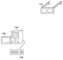
先ず、本実施形態に係るシステムの構成例について、図1を用いて説明する。図1に示す如く、本実施形態に係るシステムは、HMD1101、表示装置1103、画像処理装置1104、操作装置1105、を有する。そしてHMD1101と画像処理装置1104とは、無線若しくは有線のネットワークを介して互いにデータ通信が可能なように構成されている。HMD1101と画像処理装置1104との間の無線ネットワークには、例えば、WLAN(Wireless Local Area Network)やWPAN(Wireless Personal Area Network)を適用することができる。なお、HMD1101及び画像処理装置1104は、1つ以上の通信機器を介して互いにデータ通信を行うようにしても良い。また画像処理装置1104には、表示装置1103及び操作装置1105が接続されている。 First, a configuration example of the system according to the present embodiment will be described with reference to FIG. As shown in FIG. 1, the system according to the present embodiment includes an HMD 1101, a display device 1103, an image processing device 1104, and an operation device 1105. The HMD 1101 and the image processing device 1104 are configured to enable data communication with each other via a wireless or wired network. For example, WLAN (Wireless Local Area Network) or WPAN (Wireless Personal Area Network) can be applied to the wireless network between the HMD 1101 and the image processing device 1104. The HMD 1101 and the image processing device 1104 may perform data communication with each other via one or more communication devices. Further, a display device 1103 and an operation device 1105 are connected to the image processing device 1104.

本実施形態では、HMD1101を頭部装着型表示装置の一例として使用したケースについて説明するが、HMD1101以外の頭部装着型表示装置を用いても構わない。また、頭部装着型表示装置に限らず、ハンドヘルド型の表示装置など、他の種類の表示装置を用いても良い。 In the present embodiment, the case where the HMD1101 is used as an example of the head-mounted display device will be described, but a head-mounted display device other than the HMD1101 may be used. Further, the display device is not limited to the head-mounted display device, and other types of display devices such as a handheld display device may be used.

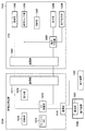
次に、HMD1101及び画像処理装置1104のそれぞれの機能構成例について、図2のブロック図を用いて説明する。 Next, each functional configuration example of the HMD 1101 and the image processing device 1104 will be described with reference to the block diagram of FIG.

先ずHMD1101について説明する。撮像部1202は、現実空間の動画像を撮像し、撮像した動画像の各フレームの画像(現実空間の撮像画像)を順次、通信部1204を介して画像処理装置1104に対して送信する。撮像部1202は、例えば、HMD1101を頭部に装着したユーザ(以下、HMDユーザと称する場合がある)の眼の近傍に位置するようにHMD1101に取り付けられる。 First, HMD1101 will be described. The imaging unit 1202 captures a moving image in the real space, and sequentially transmits an image of each frame of the captured moving image (captured image in the real space) to the image processing device 1104 via the communication unit 1204. The imaging unit 1202 is attached to the HMD 1101 so as to be located near the eyes of a user who wears the HMD 1101 on the head (hereinafter, may be referred to as an HMD user).

姿勢センサ部1203は、加速度センサやジャイロセンサ等のセンサである。姿勢センサ部1203は、「自身の姿勢を表す姿勢情報(例えばクオータ二オン)」、「自身の加速度」、「自身の位置姿勢を基準とするローカル座標系を構成する各軸(X軸、Y軸、Z軸)周りの自身の角速度」、を測定する。以下では姿勢センサ部1203が測定した姿勢情報、角速度、加速度をそれぞれ、HMD1101の姿勢情報、角速度、加速度と称する場合がある。そして姿勢センサ部1203は、測定した情報のうち姿勢情報を通信部1204を介して画像処理装置1104に対して送信する。 The attitude sensor unit 1203 is a sensor such as an acceleration sensor or a gyro sensor. The posture sensor unit 1203 has "posture information representing its own posture (for example, a quarterion)", "own acceleration", and "each axis (X-axis, Y) constituting a local coordinate system based on its own position and posture". ”, Measures its own angular velocity around the axis, Z axis). Hereinafter, the attitude information, the angular velocity, and the acceleration measured by the attitude sensor unit 1203 may be referred to as the attitude information, the angular velocity, and the acceleration of the HMD 1101, respectively. Then, the attitude sensor unit 1203 transmits the attitude information out of the measured information to the image processing device 1104 via the communication unit 1204.

なお、姿勢センサ部1203が測定するものは自身の姿勢情報、角速度、加速度の全てに限らず、このうち1つ以上であっても良いし、これらに代えて若しくは加えて自身の位置など自身に係る他の情報を測定するようにしても良い。 It should be noted that what the attitude sensor unit 1203 measures is not limited to all of its own attitude information, angular velocity, and acceleration, and may be one or more of these, and in place of or in addition to these, its own position and the like. Other such information may be measured.

表示部1206は、HMDユーザの眼前に位置するようにHMD1101に取り付けられており、動作判定部1205から出力された画像や文字を表示する。 The display unit 1206 is attached to the HMD 1101 so as to be located in front of the eyes of the HMD user, and displays images and characters output from the operation determination unit 1205.

音声出力部1208は、HMDユーザの耳(両方の耳若しくは片方の耳)に対して音声を出力可能な位置に取り付けられており、動作判定部1205から出力された音声信号に基づく音声を出力する。 The voice output unit 1208 is attached to a position where voice can be output to the ears of the HMD user (both ears or one ear), and outputs voice based on the voice signal output from the operation determination unit 1205. ..

動作判定部1205は、姿勢センサ部1203による測定結果に基づくHMD1101(HMDユーザの頭部)の動きが、酔い易い動きとして予め設定されている規定の動きに該当するのか否かを判断する。そして動作判定部1205は、HMD1101の動きが規定の動きに該当するのであれば、ユーザに対して警告を報知するべく、画像処理装置1104から受信した画像に警告を表す情報を重畳して表示部1206に出力する。また動作判定部1205は、HMD1101の動きが規定の動きに該当するのであれば、警告を表す音声の音声信号を音声出力部1208に出力する。動作判定部1205の詳細については、図3のブロック図を用いて後述する。 The motion determination unit 1205 determines whether or not the movement of the HMD 1101 (head of the HMD user) based on the measurement result by the posture sensor unit 1203 corresponds to a predetermined movement preset as a movement that is easy to get drunk. Then, if the movement of the HMD 1101 corresponds to the specified movement, the operation determination unit 1205 superimposes the information indicating the warning on the image received from the image processing device 1104 to notify the user of the warning, and the display unit 1205. Output to 1206. Further, if the movement of the HMD 1101 corresponds to the specified movement, the operation determination unit 1205 outputs a voice signal of a voice indicating a warning to the voice output unit 1208. The details of the operation determination unit 1205 will be described later with reference to the block diagram of FIG.

制御部1207は、CPU等のプロセッサと、該プロセッサが実行するコンピュータプログラムやデータが格納されているメモリと、を有する。プロセッサがメモリ内のコンピュータプログラムやデータを用いて処理を実行することで、HMD1101全体の動作制御を行うと共に、HMD1101が行うものとして後述する各処理を実行若しくは制御する。通信部1204は、画像処理装置1104との間のデータ通信を行うためのインターフェースとして機能する。 The control unit 1207 has a processor such as a CPU and a memory in which computer programs and data executed by the processor are stored. When the processor executes the process using the computer program or data in the memory, the operation of the entire HMD 1101 is controlled, and each process described later is executed or controlled as what the HMD 1101 performs. The communication unit 1204 functions as an interface for performing data communication with the image processing device 1104.

次に、画像処理装置1104について説明する。画像処理装置1104は、PC(パーソナルコンピュータ)やWS(ワークステーション)、タブレット端末装置やスマートフォン等のコンピュータ装置である。通信部1211は、HMD1101との間のデータ通信を行うためのインターフェースとして機能する。 Next, the image processing apparatus 1104 will be described. The image processing device 1104 is a computer device such as a PC (personal computer), a WS (workstation), a tablet terminal device, or a smartphone. The communication unit 1211 functions as an interface for performing data communication with the HMD 1101.

算出部1212は、HMD1101から送信された撮像画像及び姿勢情報を通信部1211を介して取得する。そして算出部1212は、該取得した撮像画像から該撮像画像を撮像したときの撮像部1202の位置を算出する。撮像画像から該撮像画像を撮像した撮像装置の位置を算出するための技術は周知であり、本実施形態では如何なる技術を採用してもよい。例えば、現実空間において位置が既知の特徴(現実物体のエッジや角など)の現実空間における3次元位置と、撮像画像中の該特徴の画像座標(2次元座標)と、に基づいて、該撮像画像を撮像した撮像装置の位置を算出する技術を採用してもよい。また、撮像装置の位置を、該撮像装置若しくは該撮像装置を有する頭部装着型表示装置に取り付けられている位置センサによる計測値に基づいて取得するようにしてもよいし、GPSを用いて撮像装置の位置を取得してもよい。つまり、算出部1212は、HMD1101から送信された撮像画像を撮像したときの撮像部1202の位置を取得することができるのであれば、如何なる技術を適用してもよい。また算出部1212は、該取得した姿勢情報が表す姿勢センサ部1203の姿勢を、撮像部1202と姿勢センサ部1203との間の相対的な姿勢関係(既知の情報であり、コンテンツDB1214に予め登録されている)を用いて変換する。この変換により、撮像部1202の姿勢を求めることができる。なお、撮像部1202の姿勢を取得するための構成についても特定の構成に限らず、例えば、撮像画像から該撮像画像を撮像したときの撮像部1202の姿勢を上記の既知の方法でもって求めるようにしても良い。 The calculation unit 1212 acquires the captured image and the attitude information transmitted from the HMD 1101 via the communication unit 1211. Then, the calculation unit 1212 calculates the position of the imaging unit 1202 when the captured image is captured from the acquired captured image. The technique for calculating the position of the image pickup apparatus that has captured the captured image from the captured image is well known, and any technique may be adopted in the present embodiment. For example, the imaging is based on the three-dimensional position in the real space of a feature whose position is known in the real space (edges, corners, etc. of a real object) and the image coordinates (two-dimensional coordinates) of the feature in the captured image. A technique of calculating the position of the image pickup device that captured the image may be adopted. Further, the position of the image pickup device may be acquired based on the measured value by the image pickup device or the position sensor attached to the head-mounted display device having the image pickup device, or the position of the image pickup device may be acquired by using GPS. The position of the device may be acquired. That is, any technique may be applied to the calculation unit 1212 as long as it can acquire the position of the image pickup unit 1202 when the captured image transmitted from the HMD 1101 is captured. Further, the calculation unit 1212 registers the posture of the posture sensor unit 1203 represented by the acquired posture information in the relative posture relationship (known information and is registered in the content DB 1214 in advance) between the image pickup unit 1202 and the posture sensor unit 1203. ) Is used to convert. By this conversion, the posture of the imaging unit 1202 can be obtained. The configuration for acquiring the posture of the imaging unit 1202 is not limited to a specific configuration, and for example, the posture of the imaging unit 1202 when the captured image is captured from the captured image is obtained by the above-mentioned known method. You can do it.

CG描画部1213は、コンテンツDB1214に登録されている仮想物体データを用いて仮想物体を構築し、該構築した仮想物体を該仮想物体データが規定する位置姿勢でもって仮想空間中に配置する。仮想物体データは、仮想物体の幾何形状、色、質感、テクスチャ等の該仮想物体の外観を規定するモデルデータ、仮想物体を配置する位置姿勢を示すデータ、仮想空間を照射する光源に係るデータ、等を含む。 The CG drawing unit 1213 constructs a virtual object using the virtual object data registered in the content DB 1214, and arranges the constructed virtual object in the virtual space with the position and orientation defined by the virtual object data. The virtual object data includes model data that defines the appearance of the virtual object such as the geometry, color, texture, and texture of the virtual object, data that indicates the position and orientation of the virtual object, and data related to a light source that irradiates the virtual space. Etc. are included.

そしてCG描画部1213は、視点(視点の位置は撮像部1202の位置、視点の姿勢は撮像部1202の姿勢)から見える仮想物体の画像を仮想空間画像として生成する。そしてCG描画部1213は、算出部1212が通信部1211を介してHMD1101から取得した撮像画像と、該生成した仮想空間画像とを合成した合成画像を複合現実空間画像として生成する。そしてCG描画部1213は、該生成した複合現実空間画像を通信部1211を介してHMD1101に対して送信する。 Then, the CG drawing unit 1213 generates an image of a virtual object that can be seen from the viewpoint (the position of the viewpoint is the position of the imaging unit 1202, and the posture of the viewpoint is the posture of the imaging unit 1202) as a virtual space image. Then, the CG drawing unit 1213 generates a composite image obtained by synthesizing the captured image acquired from the HMD 1101 by the calculation unit 1212 via the communication unit 1211 and the generated virtual space image as a mixed reality space image. Then, the CG drawing unit 1213 transmits the generated mixed reality space image to the HMD 1101 via the communication unit 1211.

制御部1219は、CPU等のプロセッサと、該プロセッサが実行するコンピュータプログラムやデータが格納されているメモリと、を有する。プロセッサがメモリ内のコンピュータプログラムやデータを用いて処理を実行することで、画像処理装置1104全体の動作制御を行うと共に、画像処理装置1104が行うものとして後述する各処理を実行若しくは制御する。通信部1215は、操作装置1105及び表示装置1103を画像処理装置1104に接続するためのインターフェースとして機能するものである。 The control unit 1219 has a processor such as a CPU and a memory in which computer programs and data executed by the processor are stored. When the processor executes the process using the computer program or data in the memory, the operation of the entire image processing device 1104 is controlled, and each process described later is executed or controlled as what the image processing device 1104 performs. The communication unit 1215 functions as an interface for connecting the operation device 1105 and the display device 1103 to the image processing device 1104.

次に、操作装置1105について説明する。操作装置1105は、キーボードなどのユーザインターフェースにより構成されており、ユーザが操作することで各種の指示を入力することができる。ユーザインターフェースはキーボードに限らず、マウスやタッチパネルなどの他の種類のインターフェースであってもよい。ユーザによる操作によって入力された指示は、通信部1221を介して画像処理装置1104に入力され、制御部1219は、該指示に応じた処理を実行する。 Next, the operating device 1105 will be described. The operation device 1105 is configured by a user interface such as a keyboard, and various instructions can be input by the user operating the operation device 1105. The user interface is not limited to the keyboard, and may be another type of interface such as a mouse or a touch panel. The instruction input by the operation by the user is input to the image processing device 1104 via the communication unit 1221, and the control unit 1219 executes the process according to the instruction.

次に、表示装置1103について説明する。表示装置1103は、CRTや液晶画面などにより構成されており、画像処理装置1104による処理結果を画像や文字などでもって表示することができる。例えば表示装置1103には、画像処理装置1104がHMD1101に出力する画像を表示することができる。また表示装置1103には、上記の警告の内容(テキストや音声)や後述するテーブルの内容等を編集するためのGUIを表示することもできる。なお、表示装置1103は、タッチパネル画面であっても良い。 Next, the display device 1103 will be described. The display device 1103 is composed of a CRT, a liquid crystal screen, or the like, and can display the processing result of the image processing device 1104 with an image, characters, or the like. For example, the display device 1103 can display an image output by the image processing device 1104 to the HMD 1101. Further, the display device 1103 can also display a GUI for editing the contents of the above warning (text or voice), the contents of the table described later, and the like. The display device 1103 may be a touch panel screen.

画像処理装置1104の上記の各機能部は何れもハードウェアで実装しても良いが、算出部1212、CG描画部1213をソフトウェア(コンピュータプログラム)で実装しても良い。後者の場合、このコンピュータプログラムはコンテンツDB1214に格納され、制御部1219がこのコンピュータプログラムを用いて処理を実行することで、算出部1212及びCG描画部1213の機能を実現することができる。 Each of the above-mentioned functional units of the image processing device 1104 may be implemented by hardware, but the calculation unit 1212 and the CG drawing unit 1213 may be implemented by software (computer program). In the latter case, this computer program is stored in the content DB 1214, and the control unit 1219 executes processing using this computer program, so that the functions of the calculation unit 1212 and the CG drawing unit 1213 can be realized.

次に、動作判定部1205の機能構成例について、図3のブロック図を用いて説明する。 Next, an example of the functional configuration of the operation determination unit 1205 will be described with reference to the block diagram of FIG.

動作定義部1301には、複数種類の「HMD1101を頭部に装着して表示部1206を観察しているユーザが酔ってしまうような該ユーザの頭部(HMD1101)の動き」(酔い動作)のそれぞれについて、酔い易さ、検知順番が格納されている。動作定義部1301に格納されている情報の構成例を図9に示す。図9のテーブルには、「下を向く」、「Roll動作」、「急な加速」、「二軸回転」の4つの酔い動作のそれぞれについて、「酔い易さ」及び「検知順番」が対応付けて登録されている。 The motion definition unit 1301 includes a plurality of types of "movements of the user's head (HMD1101) such that the user who is observing the display unit 1206 with the HMD 1101 attached to the head gets drunk" (sickness motion). For each, the ease of getting drunk and the order of detection are stored. FIG. 9 shows a configuration example of the information stored in the operation definition unit 1301. In the table of FIG. 9, "easiness of sickness" and "detection order" correspond to each of the four sickness movements of "downward", "roll movement", "sudden acceleration", and "biaxial rotation". It is registered with.

酔い動作「下を向く」の一例を図4(a)に示す。図4(a)では、HMD1101を頭部に装着したユーザ1401の頭部の向きが図4(a)の左側に示した状態(頭部が正面方向を向いている)から右側に示した状態(頭部が正の俯角方向を向いている)に変化している。 An example of the sickness motion “looking down” is shown in FIG. 4 (a). In FIG. 4A, the direction of the head of the user 1401 wearing the HMD1101 on the head is from the state shown on the left side of FIG. 4A (the head is facing the front direction) to the state shown on the right side. It has changed to (the head is facing the positive depression angle direction).

酔い動作「Roll動作」の一例を図4(b)に示す。図4(b)では、HMD1101を頭部に装着したユーザ1401の頭部が矢印で示す如く、Roll方向に回転している。 An example of the sickness motion “Roll motion” is shown in FIG. 4 (b). In FIG. 4B, the head of the user 1401 wearing the HMD 1101 on the head is rotating in the Roll direction as shown by an arrow.

酔い動作「急な加速」の一例を図4(c)に示す。図4(c)では、HMD1101を頭部に装着したユーザ1401が、矢印で示す如く、自身の首を該ユーザ1401の左側に早く振っている。 An example of the sickness motion “sudden acceleration” is shown in FIG. 4 (c). In FIG. 4 (c), the user 1401 wearing the HMD 1101 on his head is swung his head to the left side of the user 1401 as shown by the arrow.

酔い動作「二軸回転」の一例を図4(d)に示す。図4(d)では、HMD1101を頭部に装着したユーザ1401の頭部が2つの矢印で示す如く、二軸で回転(例えばパン方向及びチルト方向の両方向に回転)している。 An example of the sickness operation “biaxial rotation” is shown in FIG. 4 (d). In FIG. 4D, the head of the user 1401 wearing the HMD 1101 on the head is rotated in two axes (for example, in both the pan direction and the tilt direction) as indicated by the two arrows.

図9のテーブルでは、酔い動作「下を向く」に対応する「酔い易さ」として「段々と酔う」、酔い動作「Roll動作」に対応する「酔い易さ」として「直ぐに酔う」、が登録されている。また、図9のテーブルでは、酔い動作「急な加速」に対応する「酔い易さ」として「段々と酔う」、酔い動作「二軸回転」に対応する「酔い易さ」として「直ぐに酔う」が登録されている。「直ぐに酔う」とは、動作を行うことで直ぐに映像酔いを起こしやすい、ことを意味している。また「段々と酔う」とは、動作を続けることで映像酔いを起こしやすい、ことを意味している。このように図9のテーブルには、酔い動作ごとに、その酔い易さを示す情報が管理されている。 In the table of FIG. 9, "gradual sickness" is registered as "easiness to get sick" corresponding to the sickness movement "downward", and "immediately get sick" is registered as "easiness to get sick" corresponding to the sickness movement "Roll movement". Has been done. Further, in the table of FIG. 9, "sickness gradually" corresponds to the sickness motion "sudden acceleration", and "immediate sickness" corresponds to the sickness motion "biaxial rotation". Is registered. "Immediately get sick" means that it is easy to get a picture sickness immediately by performing an action. In addition, "gradually getting drunk" means that it is easy to cause video sickness by continuing the operation. As described above, in the table of FIG. 9, information indicating the susceptibility to sickness is managed for each sickness operation.

また、図9のテーブルでは、「下を向く」に対応する検知順番として「4」、「Roll動作」に対応する検知順番として「2」、「急な加速」に対応する検知順番として「3」、「二軸回転」に対応する検知順番として「1」が登録されている。検知順番については後述する。以下の説明では、動作定義部1301は図9のテーブルを保持しているものとして説明するが、テーブルに登録される酔い動作は図9に示した酔い動作に限らず、図9の4つの酔い動作に代えて若しくは加えて他の酔い動作を登録してもよい。また、酔い動作に対応する酔い易さや検知順番についても図9に示したものに限らない。 Further, in the table of FIG. 9, the detection order corresponding to "downward" is "4", the detection order corresponding to "Roll operation" is "2", and the detection order corresponding to "sudden acceleration" is "3". , "1" is registered as the detection order corresponding to "biaxial rotation". The detection order will be described later. In the following description, the motion definition unit 1301 will be described as holding the table of FIG. 9, but the sickness motion registered in the table is not limited to the sickness motion shown in FIG. 9, and the four sickness motions of FIG. 9 are described. Other sickness movements may be registered in place of or in addition to the movement. Further, the sickness easiness corresponding to the sickness motion and the detection order are not limited to those shown in FIG.

判定部1302は、姿勢センサ部1203による測定結果に基づくHMD1101の動きが酔い動作に該当するのかを判断する。動作定義部1301が図9のテーブルを保持している場合、判定部1302は先ず、姿勢センサ部1203による測定結果に基づくHMD1101の動きが、検知順番「1」に対応する酔い動作である「二軸回転」に該当するか否かを判断する。この判断の結果、HMD1101の動きが「二軸回転」には該当しない場合、判定部1302は、姿勢センサ部1203による測定結果に基づくHMD1101の動きが、検知順番「2」に対応する酔い動作である「Roll動作」に該当するか否かを判断する。この判断の結果、HMD1101の動きが「Roll動作」には該当しない場合、判定部1302は、姿勢センサ部1203による測定結果に基づくHMD1101の動きが、検知順番「3」に対応する酔い動作である「急な加速」に該当するか否かを判断する。この判断の結果、HMD1101の動きが「急な加速」には該当しない場合、判定部1302は、姿勢センサ部1203による測定結果に基づくHMD1101の動きが、検知順番「4」に対応する酔い動作である「下を向く」に該当するか否かを判断する。この判断の結果、HMD1101の動きが「下を向く」には該当しない場合、判定部1302は、姿勢センサ部1203による測定結果に基づくHMD1101の動きは酔い動作ではなく、「通常動作」であると判断する。 The determination unit 1302 determines whether the movement of the HMD 1101 based on the measurement result by the posture sensor unit 1203 corresponds to the sickness operation. When the motion definition unit 1301 holds the table of FIG. 9, the determination unit 1302 first determines that the movement of the HMD 1101 based on the measurement result by the posture sensor unit 1203 is a sickness operation corresponding to the detection order "1". Judge whether or not it corresponds to "axis rotation". As a result of this determination, when the movement of the HMD 1101 does not correspond to the "biaxial rotation", the determination unit 1302 determines that the movement of the HMD 1101 based on the measurement result by the posture sensor unit 1203 is a sickness operation corresponding to the detection order "2". It is determined whether or not it corresponds to a certain "Roll operation". As a result of this determination, when the movement of the HMD 1101 does not correspond to the "Roll operation", the determination unit 1302 is a sickness operation in which the movement of the HMD 1101 based on the measurement result by the posture sensor unit 1203 corresponds to the detection order "3". Judge whether or not it corresponds to "sudden acceleration". As a result of this determination, when the movement of the HMD 1101 does not correspond to "sudden acceleration", the determination unit 1302 determines that the movement of the HMD 1101 based on the measurement result by the posture sensor unit 1203 is a sickness operation corresponding to the detection order "4". Judge whether or not it corresponds to a certain "downward". As a result of this determination, when the movement of the HMD 1101 does not correspond to "downward", the determination unit 1302 determines that the movement of the HMD 1101 based on the measurement result by the posture sensor unit 1203 is not a sickness operation but a "normal operation". to decide.

それぞれの動きに対する検知順番は、直ぐ酔いにつながり易い順番となっており、図9の場合は、「二軸回転」、「Roll動作」、「急な加速」、「下を向く」の順に直ぐ酔いにつながり易い動きとなっている。 The detection order for each movement is an order that easily leads to sickness, and in the case of FIG. 9, immediately in the order of "biaxial rotation", "Roll operation", "sudden acceleration", and "downward". It is a movement that easily leads to sickness.

ここで、判定部1302が、HMD1101(頭部)の動きが酔い動作に該当するのか否かを、図4(a)〜(d)のそれぞれに示した酔い動作(「下を向く」、「Roll動作」、「急な加速」、「二軸回転」)を例にとり説明する。姿勢センサ部1203は図5(a)に示す如く、自身の位置を原点とし、撮像部1202の視線方向をX軸の正方向、撮像部1202の鉛直上向き方向をY軸の正方向、X軸及びY軸と直交する軸をZ軸とする座標系における姿勢情報、角速度、加速度を測定する。 Here, the determination unit 1302 indicates whether or not the movement of the HMD 1101 (head) corresponds to the sickness movement, as shown in FIGS. 4A to 4D, respectively. "Roll operation", "sudden acceleration", "biaxial rotation") will be described as an example. As shown in FIG. 5A, the attitude sensor unit 1203 has its own position as the origin, the line-of-sight direction of the image pickup unit 1202 is the positive direction of the X axis, the vertical upward direction of the image pickup unit 1202 is the positive direction of the Y axis, and the X axis. And, the attitude information, the angular velocity, and the acceleration in the coordinate system whose Z axis is the axis orthogonal to the Y axis are measured.

このような場合において、先ず、判定部1302がHMD1101(頭部)の動きが「下を向く」であるか否かを判断する処理について、図5(b)を用いて説明する。図5(b)の左側に示す如く、HMDユーザ1590が水平方向を観察している状態では、姿勢センサ部1203の重力軸は矢印1502で示す如くY軸の負の方向に向く。然るに、HMDユーザ1590が水平方向を観察している状態では、姿勢センサ部1203からは加速度として「Y軸の負の方向に1Gを示すベクトル」が出力される。ここでHMDユーザ1590が下を向くと、図5(b)の右側に示す如く、姿勢センサ部1203の軸が傾くため、姿勢センサ部1203から出力される加速度は、Y軸方向のベクトル1503とX軸方向のベクトル1504として出力される。HMDユーザ1590が下を向くほど、X軸方向のベクトル1504の大きさが大きくなる。そこで、例えば判定部1302は、X軸方向のベクトルのサイズが規定サイズ以上であれば、HMD1101(頭部)の動きは「下を向く」であると判断する。 In such a case, first, a process of determining whether or not the movement of the HMD 1101 (head) is “downward” by the determination unit 1302 will be described with reference to FIG. 5 (b). As shown on the left side of FIG. 5B, when the HMD user 1590 is observing the horizontal direction, the gravity axis of the attitude sensor unit 1203 faces in the negative direction of the Y axis as shown by the arrow 1502. However, when the HMD user 1590 is observing the horizontal direction, the attitude sensor unit 1203 outputs "a vector indicating 1G in the negative direction of the Y axis" as an acceleration. Here, when the HMD user 1590 faces downward, the axis of the attitude sensor unit 1203 is tilted as shown on the right side of FIG. 5B, so that the acceleration output from the attitude sensor unit 1203 is the vector 1503 in the Y-axis direction. It is output as a vector 1504 in the X-axis direction. As the HMD user 1590 faces downward, the size of the vector 1504 in the X-axis direction becomes larger. Therefore, for example, the determination unit 1302 determines that the movement of the HMD 1101 (head) is "downward" if the size of the vector in the X-axis direction is equal to or larger than the specified size.

次に、判定部1302がHMD1101(頭部)の動きが「Roll動作」であるか否かを判断する処理について、図5(c)を用いて説明する。矢印で示す如く、HMDユーザ1590が首をひねるなどして頭部をRoll方向に回転させると、姿勢センサ部1203からは、矢印1505で示す如く、X軸周りの角速度として規定値以上の角速度が出力される。そこで、例えば判定部1302は、X軸周りの角速度が規定値以上であれば、HMD1101(頭部)の動きは「Roll動作」であると判断する。 Next, a process of determining whether or not the movement of the HMD 1101 (head) is the “Roll operation” by the determination unit 1302 will be described with reference to FIG. 5 (c). As shown by the arrow, when the HMD user 1590 rotates the head in the Roll direction by twisting the neck or the like, the attitude sensor unit 1203 emits an angular velocity equal to or higher than the specified value as the angular velocity around the X-axis as shown by the arrow 1505. It is output. Therefore, for example, the determination unit 1302 determines that the movement of the HMD 1101 (head) is a "Roll operation" if the angular velocity around the X axis is equal to or higher than the specified value.

次に、判定部1302がHMD1101(頭部)の動きが「急な加速」であるか否かを判断する処理について、図5(d)を用いて説明する。図5(d)の左側に示すように、HMDユーザ1590が矢印で示す如く自身の首を早く振ると、図5(d)の右側に示すように、姿勢センサ部1203からは、矢印1506で示す如くY軸周りの角速度として規定値以上の角速度が出力される。そこで、例えば判定部1302は、Y軸周りの角速度の変化量が規定値以上であれば、HMD1101(頭部)の動きは「急な加速」であると判断する。なお、角速度の代わりに加速度を用いても良く、一定値以上の加速度が得られた場合に、HMD1101(頭部)の動きは「急な加速」であると判断してもよい。 Next, a process of determining whether or not the movement of the HMD 1101 (head) is “sudden acceleration” by the determination unit 1302 will be described with reference to FIG. 5 (d). As shown on the left side of FIG. 5 (d), when the HMD user 1590 shakes his / her head quickly as shown by the arrow, as shown on the right side of FIG. As shown, an angular velocity equal to or higher than the specified value is output as the angular velocity around the Y-axis. Therefore, for example, the determination unit 1302 determines that the movement of the HMD 1101 (head) is "sudden acceleration" if the amount of change in the angular velocity around the Y axis is equal to or greater than the specified value. Acceleration may be used instead of the angular velocity, and when an acceleration of a certain value or more is obtained, the movement of the HMD1101 (head) may be determined to be "sudden acceleration".

次に、判定部1302がHMD1101(頭部)の動きが「二軸回転」であるか否かを判断する処理について、図5(e)を用いて説明する。図5(e)に示す如く、HMDユーザ1590が自身の頭部を2つの矢印で示す如くパン方向及びチルト方向に回転させたとする。このとき姿勢センサ部1203からは、矢印1508で示す如くY軸周りの角速度として規定値以上の角速度が出力されると共に、矢印1507で示す如くZ軸周りの角速度として規定値以上の角速度が出力される。そこで、例えば判定部1302は、姿勢センサ部1203からY軸周りの角速度として規定値以上の角速度が出力され且つZ軸周りの角速度として規定値以上の角速度が出力されると、HMD1101(頭部)の動きは「二軸回転」であると判断する。 Next, a process of determining whether or not the movement of the HMD 1101 (head) is “biaxial rotation” by the determination unit 1302 will be described with reference to FIG. 5 (e). As shown in FIG. 5 (e), it is assumed that the HMD user 1590 rotates his / her head in the pan direction and the tilt direction as indicated by the two arrows. At this time, the attitude sensor unit 1203 outputs an angular velocity equal to or higher than the specified value as the angular velocity around the Y-axis as shown by arrow 1508, and outputs an angular velocity equal to or higher than the specified value as the angular velocity around the Z-axis as shown by arrow 1507. NS. Therefore, for example, when the attitude sensor unit 1203 outputs an angular velocity equal to or higher than a specified value as the angular velocity around the Y axis and outputs an angular velocity equal to or higher than the specified value as the angular velocity around the Z axis, the determination unit 1302 (head) It is judged that the movement of is "biaxial rotation".

このようにして判定部1302は、姿勢センサ部1203から出力される測定結果に基づいてHMD1101(頭部)の動きが何れの酔い動作であるのかを判断することができる。なお、姿勢センサ部1203による測定結果がどのような動きを示すのかを判断するための処理については特定の処理に限らない。 In this way, the determination unit 1302 can determine which sickness movement the movement of the HMD 1101 (head) is based on the measurement result output from the posture sensor unit 1203. The process for determining what kind of movement the measurement result by the posture sensor unit 1203 shows is not limited to a specific process.

そして判定部1302は、HMD1101(頭部)の動きが酔い動作に該当すると判断した場合には、保持部1303に格納されている文字情報のうち、該酔い動作に対応する酔い易さに対応する文字情報を取得する。文字情報は、警告を示す文字/文字列(警告メッセージ)である。本実施形態では、保持部1303には、酔い易さごとに対応する文字情報が保持されているものとする。例えば、酔い易さが「段々と酔う」と「直ぐに酔う」の2種類である場合、保持部1303には、「段々と酔う」に対応する文字情報、「直ぐに酔う」に対応する文字情報、が格納されている。然るに例えば判定部1302は、HMD1101(頭部)の動きが「下を向く」であると判断した場合、図9のテーブルより、対応する酔い易さは「段々と酔う」であるから、保持部1303から酔い易さ「段々と酔う」に対応付けられている文字情報を取得する。また例えば判定部1302はHMD1101(頭部)の動きが「Roll動作」であると判断した場合、図9のテーブルより、対応する酔い易さは「直ぐに酔う」であるから、保持部1303から酔い易さ「直ぐに酔う」に対応付けられている文字情報を取得する。なお、保持部1303は、酔い易さごとに対応する文字情報を保持することに加えて若しくは代えて、酔い動作ごとに対応する文字情報を保持するようにしてもよい。この場合、判定部1302は、HMD1101(頭部)の動きに対応する文字情報及び/又はHMD1101(頭部)の動きに対応する酔い易さに対応する文字情報を保持部1303から取得することになる。そして判定部1302は、保持部1303から文字情報を取得すると、該取得した文字情報を重畳部1304に対して送出する。 Then, when the determination unit 1302 determines that the movement of the HMD 1101 (head) corresponds to the sickness operation, the determination unit 1302 corresponds to the sickness easiness corresponding to the sickness operation among the character information stored in the holding unit 1303. Get text information. The character information is a character / character string (warning message) indicating a warning. In the present embodiment, it is assumed that the holding unit 1303 holds the corresponding character information for each susceptibility to sickness. For example, when there are two types of susceptibility to getting drunk, "getting drunk gradually" and "getting drunk immediately", the holding unit 1303 has character information corresponding to "getting drunk gradually" and character information corresponding to "getting drunk immediately". Is stored. However, for example, when the determination unit 1302 determines that the movement of the HMD 1101 (head) is "downward", the corresponding susceptibility to sickness is "gradually sick" from the table of FIG. The character information associated with the ease of getting drunk "getting drunk gradually" is acquired from 1303. Further, for example, when the determination unit 1302 determines that the movement of the HMD 1101 (head) is the "Roll operation", the corresponding susceptibility to sickness is "immediately sick" from the table of FIG. Ease Acquires the character information associated with "immediately get drunk". In addition to or instead of holding the character information corresponding to each susceptibility to sickness, the holding unit 1303 may hold the character information corresponding to each sickness operation. In this case, the determination unit 1302 acquires the character information corresponding to the movement of the HMD 1101 (head) and / or the character information corresponding to the susceptibility to sickness corresponding to the movement of the HMD 1101 (head) from the holding unit 1303. Become. Then, when the determination unit 1302 acquires the character information from the holding unit 1303, the determination unit 1302 sends the acquired character information to the superimposing unit 1304.

また判定部1302は、HMD1101(頭部)の動きが酔い動作に該当すると判断した場合には、保持部1305に格納されている音声データのうち、該酔い動作に対応する酔い易さに対応する音声データを取得する。本実施形態では、保持部1305には、酔い易さごとに対応する音声データが保持されているものとする。例えば、酔い易さが「段々と酔う」と「直ぐに酔う」の2種類である場合、保持部1305には、「段々と酔う」に対応する音声データ、「直ぐに酔う」に対応する音声データ、が格納されている。然るに例えば判定部1302はHMD1101(頭部)の動きが「下を向く」であると判断した場合、図9のテーブルより、対応する酔い易さは「段々と酔う」であるから、保持部1305から酔い易さ「段々と酔う」に対応付けられている音声データを取得する。また例えば判定部1302はHMD1101(頭部)の動きが「Roll動作」であると判断した場合、図9のテーブルより対応する酔い易さは「直ぐに酔う」であるから、保持部1305から酔い易さ「直ぐに酔う」に対応付けられている音声データを取得する。なお、保持部1305は、酔い易さごとに対応する音声データを保持することに加えて若しくは代えて、酔い動作ごとに対応する音声データを保持するようにしてもよい。この場合、判定部1302は、HMD1101(頭部)の動きに対応する音声データ及び/又はHMD1101(頭部)の動きに対応する酔い易さに対応する音声データを保持部1305から取得することになる。そして判定部1302は、保持部1305から音声データを取得すると、該取得した音声データを音声生成部1306に対して送出する。 Further, when the determination unit 1302 determines that the movement of the HMD 1101 (head) corresponds to the sickness operation, the determination unit 1302 corresponds to the sickness easiness corresponding to the sickness operation among the voice data stored in the holding unit 1305. Get voice data. In the present embodiment, it is assumed that the holding unit 1305 holds voice data corresponding to each susceptibility to sickness. For example, when there are two types of susceptibility to getting drunk, "getting drunk gradually" and "getting drunk immediately", the holding unit 1305 contains voice data corresponding to "getting drunk gradually" and voice data corresponding to "getting drunk immediately". Is stored. However, for example, when the determination unit 1302 determines that the movement of the HMD 1101 (head) is "downward", the corresponding susceptibility to sickness is "gradually sick" from the table of FIG. 9, so that the holding unit 1305 The voice data associated with the ease of getting drunk "getting drunk gradually" is acquired from. Further, for example, when the determination unit 1302 determines that the movement of the HMD 1101 (head) is the "Roll operation", the corresponding sickness is "immediately sick" from the table of FIG. Get the voice data associated with "Immediately get drunk". In addition to or instead of holding the voice data corresponding to each susceptibility to sickness, the holding unit 1305 may hold the voice data corresponding to each sickness operation. In this case, the determination unit 1302 decides to acquire the voice data corresponding to the movement of the HMD 1101 (head) and / or the voice data corresponding to the susceptibility to sickness corresponding to the movement of the HMD 1101 (head) from the holding unit 1305. Become. Then, when the determination unit 1302 acquires the voice data from the holding unit 1305, the determination unit 1302 sends the acquired voice data to the voice generation unit 1306.

重畳部1304は、判定部1302から文字情報を取得した場合、通信部1204を介して画像処理装置1104から受信した複合現実空間画像に該文字情報が示すメッセージを重畳し、該メッセージが重畳された複合現実空間画像を表示部1206に送出する。一方、重畳部1304は、判定部1302から文字情報を取得していない場合には、通信部1204を介して画像処理装置1104から受信した複合現実空間画像を表示部1206に対して送出する。 When the superimposing unit 1304 acquires the character information from the determination unit 1302, the superimposing unit 1304 superimposes the message indicated by the character information on the mixed reality space image received from the image processing device 1104 via the communication unit 1204, and the superimposing unit 1304 superimposes the message. The mixed reality space image is sent to the display unit 1206. On the other hand, when the superimposing unit 1304 does not acquire the character information from the determination unit 1302, the superimposing unit 1304 sends the mixed reality space image received from the image processing device 1104 via the communication unit 1204 to the display unit 1206.

例えば、重畳部1304が画像処理装置1104から図6(a)に示した複合現実空間画像を受信したとする。このとき、現在のHMD1101の動きが酔い動作ではない通常動作である場合には、重畳部1304は、画像処理装置1104から受信した図6(a)の複合現実空間画像を、警告メッセージを重畳することなく表示部1206に対して送出する。一方、現在のHMD1101の動きが酔い動作であり且つ該酔い動作の酔い易さが「段々と酔う」であるとする。このとき重畳部1304は図6(b)に示す如く、画像処理装置1104から受信した図6(a)の複合現実空間画像に、HMDユーザが現在の動作(頭部の動作)を続けると映像酔いになる可能性があることを報知するための警告メッセージ601を重畳する。そして重畳部1304は、警告メッセージ601が重畳された複合現実空間画像を表示部1206に対して送出する。また、現在のHMD1101の動きが酔い動作であり且つ該酔い動作の酔い易さが「直ぐに酔う」であるとする。このとき重畳部1304は図6(c)に示す如く、画像処理装置1104から受信した図6(a)の複合現実空間画像に対して、HMDユーザの現在の動作(頭部の動作)は映像酔いになる可能性があることを報知するための警告メッセージ602を重畳する。そして重畳部1304は、警告メッセージ602が重畳された複合現実空間画像を表示部1206に対して送出する。なお、警告メッセージの内容や表示方法については特定の内容、表示方法に限らない。 For example, it is assumed that the superimposing unit 1304 receives the mixed reality space image shown in FIG. 6A from the image processing device 1104. At this time, if the current movement of the HMD 1101 is a normal operation other than a drunken operation, the superimposing unit 1304 superimposes a warning message on the mixed reality space image of FIG. 6A received from the image processing device 1104. It is sent to the display unit 1206 without any notice. On the other hand, it is assumed that the current movement of the HMD 1101 is a sickness movement, and the sickness of the sickness movement is "gradually drunk". At this time, as shown in FIG. 6B, the superimposing unit 1304 displays an image when the HMD user continues the current operation (movement of the head) on the mixed reality space image of FIG. 6A received from the image processing device 1104. A warning message 601 for notifying that there is a possibility of getting sick is superimposed. Then, the superimposition unit 1304 sends a mixed reality space image on which the warning message 601 is superimposed to the display unit 1206. Further, it is assumed that the current movement of the HMD 1101 is a sickness motion, and the sickness of the sickness motion is "immediately sick". At this time, as shown in FIG. 6 (c), the superimposing unit 1304 is an image of the current motion (head motion) of the HMD user with respect to the mixed reality space image of FIG. 6 (a) received from the image processing device 1104. A warning message 602 for notifying that there is a possibility of getting sick is superimposed. Then, the superimposition unit 1304 sends a mixed reality space image on which the warning message 602 is superposed to the display unit 1206. The content and display method of the warning message are not limited to the specific content and display method.

音声生成部1306は、判定部1302から音声データを取得した場合には、該音声データに基づく音声信号を生成して音声出力部1208に対して送出する。これにより、現在のHMD1101の動きが酔い動作である場合には、その酔い易さに応じた警告を示す音声が音声出力部1208から出力される。つまり、酔い易さが「段々と酔う」であれば、HMDユーザが現在の動作(頭部の動作)を続けると映像酔いになる可能性があることを報知するための音声が音声出力部1208から出力される。一方、酔い易さが「直ぐに酔う」であれば、HMDユーザの現在の動作(頭部の動作)は映像酔いになる可能性があることを報知するための音声が音声出力部1208から出力される。一方、現在のHMD1101の動きが酔い動作ではなく通常動作である場合には、判定部1302は音声データを音声生成部1306に対して送出しないので、音声出力部1208からは何も音声が出力されない。 When the voice data is acquired from the determination unit 1302, the voice generation unit 1306 generates a voice signal based on the voice data and sends it to the voice output unit 1208. As a result, when the current movement of the HMD 1101 is a sickness operation, a voice indicating a warning according to the susceptibility to the sickness is output from the voice output unit 1208. That is, if the susceptibility to sickness is "gradually sick", the audio for notifying that the HMD user may get sick if the current movement (head movement) is continued is the audio output unit 1208. Is output from. On the other hand, if the susceptibility to sickness is "immediately sick", the audio output unit 1208 outputs a voice for notifying that the current movement (head movement) of the HMD user may cause video sickness. NS. On the other hand, when the current movement of the HMD 1101 is not a drunken movement but a normal operation, the determination unit 1302 does not send voice data to the voice generation unit 1306, so that no voice is output from the voice output unit 1208. ..

HMDユーザへの警告の報知は、表示部1206による上記の表示報知のみで行っても良いし、音声出力部1208による上記の音声報知のみで行っても良いし、上記の表示報知及び音声報知の両方でもって警告を報知するようにしても良い。 The warning to the HMD user may be notified only by the above-mentioned display notification by the display unit 1206, or may be performed only by the above-mentioned voice notification by the voice output unit 1208, or the above-mentioned display notification and voice notification. The warning may be notified by both.

次に、HMD1101が1フレーム分の複合現実空間画像を表示部1206に表示するために行う処理について、同処理のフローチャートを示す図7を用いて説明する。HMD1101は図7のフローチャートに従った処理を繰り返し行うことで、複数フレーム分の複合現実空間画像を表示部1206に表示することができる。 Next, a process performed by the HMD 1101 for displaying a mixed reality space image for one frame on the display unit 1206 will be described with reference to FIG. 7 showing a flowchart of the process. The HMD 1101 can display a mixed reality space image for a plurality of frames on the display unit 1206 by repeating the process according to the flowchart of FIG. 7.

ステップS1701では、撮像部1202は、現実空間を撮像することで該現実空間の撮像画像を取得し、該取得した撮像画像を通信部1204を介して画像処理装置1104に対して送信する。ステップS1702では、姿勢センサ部1203は、自身の姿勢情報、加速度、角速度を測定することで取得し、該取得した姿勢情報を通信部1204を介して画像処理装置1104に対して送信する。 In step S1701, the imaging unit 1202 acquires an image captured in the real space by imaging the real space, and transmits the acquired image to the image processing device 1104 via the communication unit 1204. In step S1702, the posture sensor unit 1203 acquires its own attitude information, acceleration, and angular velocity, and transmits the acquired attitude information to the image processing device 1104 via the communication unit 1204.

ステップS1703では、重畳部1304は、画像処理装置1104から送信された複合現実空間画像を、通信部1204を介して受信する。ステップS1705で判定部1302は、ステップS1702で姿勢センサ部1203が取得した測定結果(姿勢情報、角速度、加速度)に基づくHMD1101(HMDユーザの頭部)の動きが通常動作であるのか、何れかの酔い動作であるのかを判断する。ステップS1705における処理の詳細について、図8のフローチャートを用いて説明する。 In step S1703, the superimposing unit 1304 receives the mixed reality space image transmitted from the image processing device 1104 via the communication unit 1204. In step S1705, the determination unit 1302 determines whether the movement of the HMD 1101 (HMD user's head) based on the measurement results (posture information, angular velocity, acceleration) acquired by the attitude sensor unit 1203 in step S1702 is a normal operation. Determine if it is a sickness action. The details of the process in step S1705 will be described with reference to the flowchart of FIG.

ステップS1801では、判定部1302は、姿勢センサ部1203が取得した測定結果の一部若しくは全部が、動作定義部1301が保持する図9のテーブルにおいて検知順番が「1」である酔い動作「二軸回転」に該当する条件を満たすか否かを判断する。この判断処理の一例については図5(e)を用いて説明した通りである。 In step S1801, the determination unit 1302 has a sickness operation “biaxial” in which the detection order is “1” in the table of FIG. 9 held by the operation definition unit 1301 for a part or all of the measurement results acquired by the posture sensor unit 1203. Judge whether or not the condition corresponding to "rotation" is satisfied. An example of this determination process is as described with reference to FIG. 5 (e).

この判断の結果、姿勢センサ部1203が取得した測定結果の一部若しくは全部が、酔い動作「二軸回転」に該当する条件を満たす(姿勢センサ部1203による測定結果が示す動きが「二軸回転」に該当する)、とする。このとき判定部1302は、姿勢センサ部1203による測定結果に基づくHMD1101(頭部)の動きが「二軸回転」であると判断して、処理はステップS1805に進む。一方、姿勢センサ部1203が取得した測定結果の一部若しくは全部が、酔い動作「二軸回転」に該当する条件を満たさない(姿勢センサ部1203による測定結果が示す動きが「二軸回転」には該当しない)場合には、処理はステップS1802に進む。 As a result of this determination, a part or all of the measurement results acquired by the attitude sensor unit 1203 satisfy the condition corresponding to the sickness operation "biaxial rotation" (the movement indicated by the measurement result by the attitude sensor unit 1203 is "biaxial rotation". ”). At this time, the determination unit 1302 determines that the movement of the HMD 1101 (head) based on the measurement result by the posture sensor unit 1203 is "biaxial rotation", and the process proceeds to step S1805. On the other hand, a part or all of the measurement results acquired by the posture sensor unit 1203 do not satisfy the condition corresponding to the sickness operation "biaxial rotation" (the movement indicated by the measurement result by the posture sensor unit 1203 becomes "biaxial rotation". Does not apply), the process proceeds to step S1802.

ステップS1802では判定部1302は、姿勢センサ部1203が取得した測定結果の一部若しくは全部が、動作定義部1301が保持する図9のテーブルにおいて検知順番が「2」である酔い動作「Roll動作」に該当する条件を満たすか否かを判断する。この判断処理の一例については図5(c)を用いて説明した通りである。 In step S1802, the determination unit 1302 has a sickness operation “Roll operation” in which the detection order is “2” in the table of FIG. 9 held by the operation definition unit 1301 for a part or all of the measurement results acquired by the posture sensor unit 1203. Judge whether or not the conditions corresponding to are satisfied. An example of this determination process is as described with reference to FIG. 5 (c).

この判断の結果、姿勢センサ部1203が取得した測定結果の一部若しくは全部が、酔い動作「Roll動作」に該当する条件を満たす(姿勢センサ部1203による測定結果が示す動きが「Roll動作」に該当する)、とする。このとき判定部1302は、姿勢センサ部1203による測定結果に基づくHMD1101(頭部)の動きが「Roll動作」であると判断して、処理はステップS1805に進む。一方、姿勢センサ部1203が取得した測定結果の一部若しくは全部が、酔い動作「Roll動作」に該当する条件を満たさない(姿勢センサ部1203による測定結果が示す動きが「Roll動作」には該当しない)場合には、処理はステップS1803に進む。 As a result of this determination, a part or all of the measurement results acquired by the posture sensor unit 1203 satisfy the condition corresponding to the sickness operation "Roll operation" (the movement indicated by the measurement result by the attitude sensor unit 1203 becomes the "Roll operation". Applicable). At this time, the determination unit 1302 determines that the movement of the HMD 1101 (head) based on the measurement result by the posture sensor unit 1203 is the “Roll operation”, and the process proceeds to step S1805. On the other hand, a part or all of the measurement results acquired by the posture sensor unit 1203 do not satisfy the condition corresponding to the sickness operation "Roll operation" (the movement indicated by the measurement result by the attitude sensor unit 1203 corresponds to the "Roll operation". If not), the process proceeds to step S1803.

ステップS1803では、判定部1302は、姿勢センサ部1203が取得した測定結果の一部若しくは全部が、動作定義部1301が保持する図9のテーブルにおいて検知順番が「3」である酔い動作「急な加速」に該当する条件を満たすか否かを判断する。この判断処理の一例については図5(d)を用いて説明した通りである。 In step S1803, the determination unit 1302 has a sickness operation “sudden” in which the detection order is “3” in the table of FIG. 9 held by the operation definition unit 1301 for a part or all of the measurement results acquired by the posture sensor unit 1203. Judge whether or not the conditions corresponding to "acceleration" are met. An example of this determination process is as described with reference to FIG. 5 (d).

この判断の結果、姿勢センサ部1203が取得した測定結果の一部若しくは全部が、酔い動作「急な加速」に該当する条件を満たす(姿勢センサ部1203による測定結果が示す動きが「急な加速」に該当する)、とする。このとき判定部1302は、姿勢センサ部1203による測定結果に基づくHMD1101(頭部)の動きが「急な加速」であると判断して、処理はステップS1805に進む。一方、姿勢センサ部1203が取得した測定結果の一部若しくは全部が、酔い動作「急な加速」に該当する条件を満たさない(姿勢センサ部1203による測定結果が示す動きが「急な加速」には該当しない)場合には、処理はステップS1804に進む。 As a result of this determination, a part or all of the measurement results acquired by the posture sensor unit 1203 satisfy the condition corresponding to the sickness operation "sudden acceleration" (the movement indicated by the measurement result by the posture sensor unit 1203 is "sudden acceleration". ”). At this time, the determination unit 1302 determines that the movement of the HMD 1101 (head) based on the measurement result by the posture sensor unit 1203 is “sudden acceleration”, and the process proceeds to step S1805. On the other hand, some or all of the measurement results acquired by the posture sensor unit 1203 do not satisfy the condition corresponding to the sickness operation "sudden acceleration" (the movement indicated by the measurement result by the posture sensor unit 1203 becomes "sudden acceleration". Does not apply), the process proceeds to step S1804.

ステップS1804では、判定部1302は、姿勢センサ部1203が取得した測定結果の一部若しくは全部が、動作定義部1301が保持する図9のテーブルにおいて検知順番が「4」である酔い動作「下を向く」に該当する条件を満たすか否かを判断する。この判断処理の一例については図5(b)を用いて説明した通りである。 In step S1804, the determination unit 1302 has a sickness operation "below" in which the detection order is "4" in the table of FIG. 9 held by the operation definition unit 1301 for a part or all of the measurement results acquired by the posture sensor unit 1203. Judge whether or not the conditions corresponding to "Face" are met. An example of this determination process is as described with reference to FIG. 5 (b).

この判断の結果、姿勢センサ部1203が取得した測定結果の一部若しくは全部が、酔い動作「下を向く」に該当する条件を満たす(姿勢センサ部1203による測定結果が示す動きが「下を向く」に該当する)、とする。このとき判定部1302は、姿勢センサ部1203による測定結果に基づくHMD1101(頭部)の動きが「下を向く」であると判断して、処理はステップS1805に進む。一方、姿勢センサ部1203が取得した測定結果の一部若しくは全部が、酔い動作「下を向く」に該当する条件を満たさない(姿勢センサ部1203による測定結果が示す動きが「下を向く」には該当しない)、とする。このとき判定部1302は、姿勢センサ部1203による測定結果に基づくHMD1101(頭部)の動きが通常動作であると判断して、処理はステップS1706に進む。 As a result of this determination, a part or all of the measurement results acquired by the posture sensor unit 1203 satisfy the condition corresponding to the sickness operation "downward" (the movement indicated by the measurement result by the posture sensor unit 1203 is "downward". ”). At this time, the determination unit 1302 determines that the movement of the HMD 1101 (head) based on the measurement result by the posture sensor unit 1203 is "downward", and the process proceeds to step S1805. On the other hand, some or all of the measurement results acquired by the posture sensor unit 1203 do not satisfy the condition corresponding to the sickness operation "downward" (the movement indicated by the measurement result by the posture sensor unit 1203 is "downward". Does not apply). At this time, the determination unit 1302 determines that the movement of the HMD 1101 (head) based on the measurement result by the posture sensor unit 1203 is a normal operation, and the process proceeds to step S1706.

ステップS1805では、判定部1302は、姿勢センサ部1203による測定結果に基づくHMD1101(頭部)の動きに該当する酔い動作に対応する酔い易さを、動作定義部1301が保持する図9のテーブルから取得する。そして処理はステップS1706に進む。 In step S1805, the determination unit 1302 determines the sickness corresponding to the sickness motion corresponding to the movement of the HMD 1101 (head) based on the measurement result by the posture sensor unit 1203 from the table of FIG. 9 held by the motion definition unit 1301. get. Then, the process proceeds to step S1706.

図7に戻って、次に、ステップS1706では、判定部1302は、ステップS1705における処理の結果、HMD1101(頭部)の動きは通常動作であるか否かを判断する。この判断の結果、HMD1101(頭部)の動きが通常動作であれば、処理はステップS1707に進む。一方、HMD1101(頭部)の動きが通常動作ではない(何れかの酔い動作)であれば、処理はステップS1708に進む。 Returning to FIG. 7, next, in step S1706, the determination unit 1302 determines whether or not the movement of the HMD 1101 (head) is a normal operation as a result of the processing in step S1705. As a result of this determination, if the movement of the HMD1101 (head) is a normal operation, the process proceeds to step S1707. On the other hand, if the movement of the HMD1101 (head) is not a normal movement (any of the sickness movements), the process proceeds to step S1708.

ステップS1707では、重畳部1304は、上記のステップS1703において画像処理装置1104から受信した複合現実空間画像を表示部1206に対して送出することで、該複合現実空間画像を表示部1206に表示させる。 In step S1707, the superimposing unit 1304 sends the mixed reality space image received from the image processing device 1104 in step S1703 to the display unit 1206, so that the mixed reality space image is displayed on the display unit 1206.

ステップS1708では、判定部1302は、上記のステップS1805で取得した酔い易さが「直ぐに酔う」であるか否かを判断する。この判断の結果、上記のステップS1805で取得した酔い易さが「直ぐに酔う」であれば、処理はステップS1709に進む。一方、上記のステップS1805で取得した酔い易さが「段々と酔う」であれば、処理はステップS1710に進む。 In step S1708, the determination unit 1302 determines whether or not the sickness acquired in step S1805 is "immediately sick". As a result of this determination, if the sickness acquired in step S1805 is "immediately sick", the process proceeds to step S1709. On the other hand, if the sickness acquired in step S1805 is "gradually sick", the process proceeds to step S1710.

ステップS1709では、判定部1302は、「直ぐに酔う」に対応する文字情報を保持部1303から取得し、該取得した文字情報を重畳部1304に対して送出する。重畳部1304は、判定部1302から受けた文字情報が示す警告メッセージを、上記のステップS1703において画像処理装置1104から受信した複合現実空間画像に重畳し、警告メッセージが重畳された複合現実空間画像を表示部1206に送出する。 In step S1709, the determination unit 1302 acquires the character information corresponding to "immediately get drunk" from the holding unit 1303, and sends the acquired character information to the superimposing unit 1304. The superimposing unit 1304 superimposes the warning message indicated by the character information received from the determination unit 1302 on the mixed reality space image received from the image processing device 1104 in step S1703, and superimposes the mixed reality space image on which the warning message is superposed. It is sent to the display unit 1206.

ステップS1710では、判定部1302は、「段々と酔う」に対応する文字情報を保持部1303から取得し、該取得した文字情報を重畳部1304に対して送出する。重畳部1304は、判定部1302から受けた文字情報が示す警告メッセージを、上記のステップS1703において画像処理装置1104から受信した複合現実空間画像に重畳し、警告メッセージが重畳された複合現実空間画像を表示部1206に送出する。 In step S1710, the determination unit 1302 acquires the character information corresponding to "gradually getting drunk" from the holding unit 1303, and sends the acquired character information to the superimposing unit 1304. The superimposing unit 1304 superimposes the warning message indicated by the character information received from the determination unit 1302 on the mixed reality space image received from the image processing device 1104 in step S1703, and superimposes the mixed reality space image on which the warning message is superposed. It is sent to the display unit 1206.

なお、図7のフローチャートでは、姿勢センサ部1203による測定結果に基づくHMD1101(頭部)の動きが酔い動作である場合における警告の報知として表示報知のみを示している。しかし、ステップS1709,S1710のそれぞれにおいて対応する音声報知を更に行うようにしても良い。即ちステップS1709では「直ぐに酔う」に対応する音声データに基づく音声通知を表示通知に加えて又は代えて行い、ステップS1710では「段々と酔う」に対応する音声データに基づく音声通知を表示通知に加えて又は代えて行うようにしても良い。 In the flowchart of FIG. 7, only the display notification is shown as a warning notification when the movement of the HMD 1101 (head) based on the measurement result by the posture sensor unit 1203 is a drunken movement. However, the corresponding voice notification may be further performed in each of steps S1709 and S1710. That is, in step S1709, the voice notification based on the voice data corresponding to "immediately getting drunk" is added to or in place of the display notification, and in step S1710, the voice notification based on the voice data corresponding to "gradually getting drunk" is added to the display notification. Or instead, it may be done.

このように本実施形態によれば、HMDユーザが酔いを発生させやすい頭部の動きを行った場合には警告を通知することで、HMDユーザに注意喚起を行ってHMDユーザに認識させることができる。 As described above, according to the present embodiment, when the HMD user makes a head movement that tends to cause sickness, the HMD user is alerted and recognized by the HMD user by notifying the warning. can.

<第1の実施形態の変形例>
第1の実施形態では、HMD1101が有する各機能部は何れもハードウェアで実装されているものとして説明した。しかし、動作判定部1205の一部の機能(例えば、図3の判定部1302、重畳部1304、音声生成部1306)についてはソフトウェア(コンピュータプログラム)で実装しても良い。この場合、このコンピュータプログラムは制御部1207が有するメモリに格納されている。そして、制御部1207が有するプロセッサが該コンピュータプログラムを実行することで、判定部1302、重畳部1304、音声生成部1306の各機能部の機能を実現することができる。
<Modified example of the first embodiment>
In the first embodiment, it has been described that each functional part of the HMD 1101 is implemented by hardware. However, some functions of the operation determination unit 1205 (for example, the determination unit 1302 in FIG. 3, the superimposition unit 1304, and the voice generation unit 1306) may be implemented by software (computer program). In this case, this computer program is stored in the memory of the control unit 1207. Then, when the processor included in the control unit 1207 executes the computer program, the functions of the determination unit 1302, the superimposition unit 1304, and the voice generation unit 1306 can be realized.

第1の実施形態では、加速度センサやジャイロセンサ等のセンサにより上記の姿勢情報、加速度、角速度を測定していたが、他の手法を用いてHMD1101(頭部)の動きを取得するようにしても構わない。例えば、磁気センサ、光学式センサ、超音波センサを用いてHMD1101の位置や姿勢を測定し、HMD1101若しくは画像処理装置1104が、該測定した位置や姿勢の変化から加速度や角速度等を求めるようにしても構わない。また、現実空間中にHMDユーザを撮像する撮像装置を設置し、HMD1101若しくは画像処理装置1104が、該撮像装置による撮像画像からHMDユーザの頭部の姿勢情報、加速度、角速度を求めるようにしても構わない。 In the first embodiment, the above-mentioned attitude information, acceleration, and angular velocity are measured by sensors such as an acceleration sensor and a gyro sensor, but the movement of the HMD1101 (head) is acquired by using another method. It doesn't matter. For example, a magnetic sensor, an optical sensor, or an ultrasonic sensor is used to measure the position and orientation of the HMD 1101, and the HMD 1101 or the image processing device 1104 obtains the acceleration, the angular velocity, or the like from the change in the measured position or posture. It doesn't matter. Further, even if an image pickup device for imaging the HMD user is installed in the real space, the HMD 1101 or the image processing device 1104 obtains the posture information, acceleration, and angular velocity of the head of the HMD user from the image captured by the image pickup device. I do not care.

また、第1の実施形態では、警告の報知を表示及び/又は音声によって行ったが、他の報知方法でもって警告を報知するようにしても良い。例えば、HMD1101にバイブレータを搭載し、現在のHMD1101(頭部)の動きに対応する酔い易さに応じた振動パターンでもってHMDユーザに警告や酔い易さを報知しても良い。また、ランプの点灯/点滅パターンでもって警告や酔い易さを報知しても良い。その場合、例えば、画像処理装置1104が現在のHMD1101(頭部)の動きに対応する酔い易さに応じてランプの点灯/点滅パターンを制御することで、警告や酔い易さを報知しても良い。 Further, in the first embodiment, the warning is notified by display and / or voice, but the warning may be notified by another notification method. For example, the HMD 1101 may be equipped with a vibrator to notify the HMD user of a warning or the susceptibility to sickness with a vibration pattern corresponding to the current movement of the HMD 1101 (head) according to the susceptibility to sickness. In addition, a warning or susceptibility to sickness may be notified by a lamp lighting / blinking pattern. In that case, for example, even if the image processing device 1104 notifies the warning or the sickness by controlling the lighting / blinking pattern of the lamp according to the sickness corresponding to the current movement of the HMD1101 (head). good.

また、第1の実施形態では、HMD1101はビデオシースルー型のHMDであるものとして説明したが、光学シースルー型のHMDを採用しても良い。その場合、視点の位置は、センサなど上記の様々な周知技術を用いて求める必要がある。また、画像処理装置1104は生成した仮想空間画像をHMD1101に送出する。そして重畳部1304は、判定部1302から文字情報を取得した場合には、画像処理装置1104から受信した仮想空間画像上に該文字情報に応じた警告メッセージを重畳し、該警告メッセージを重畳した仮想空間画像を表示部1206に表示する。一方、重畳部1304は、判定部1302から文字情報を取得していない場合には、画像処理装置1104から受信した仮想空間画像を表示部1206に表示する。 Further, in the first embodiment, the HMD 1101 has been described as being a video see-through type HMD, but an optical see-through type HMD may be adopted. In that case, the position of the viewpoint needs to be obtained by using the above-mentioned various well-known techniques such as a sensor. Further, the image processing device 1104 sends the generated virtual space image to the HMD 1101. Then, when the superimposing unit 1304 acquires the character information from the determination unit 1302, the superimposing unit 1304 superimposes a warning message corresponding to the character information on the virtual space image received from the image processing device 1104, and the superimposing unit 1304 superimposes the warning message on the virtual space image. The spatial image is displayed on the display unit 1206. On the other hand, when the superimposing unit 1304 does not acquire the character information from the determination unit 1302, the superimposing unit 1304 displays the virtual space image received from the image processing device 1104 on the display unit 1206.

また、第1の実施形態では、警告メッセージの代わりに若しくは加えて警告画像を複合現実空間画像に重畳させるようにしても良い。警告画像は、例えば、警告を表すマークやキャラクタの画像等、警告に関連する画像である。警告画像は予め作成された2次元画像であっても良いし、重畳部1304が視点の位置姿勢に基づいて生成した3次元仮想物体のCG画像であっても良い。 Further, in the first embodiment, the warning image may be superimposed on the mixed reality space image instead of or in addition to the warning message. The warning image is an image related to the warning, such as a mark representing a warning or an image of a character. The warning image may be a two-dimensional image created in advance, or may be a CG image of a three-dimensional virtual object generated by the superimposing unit 1304 based on the position and orientation of the viewpoint.

また、第1の実施形態では加速度は姿勢センサ部1203が測定していたが、加速度の取得方法は特定の取得方法に限らない。例えば、HMD1101若しくは画像処理装置1104は、撮像部1202の位置を取得した場合には、位置の変化に基づいて加速度を求めても良い。 Further, in the first embodiment, the acceleration is measured by the posture sensor unit 1203, but the method of acquiring the acceleration is not limited to the specific acquisition method. For example, when the HMD 1101 or the image processing device 1104 acquires the position of the image pickup unit 1202, the acceleration may be obtained based on the change in the position.

また、第1の実施形態では、警告の内容は、HMDユーザが現在の動作(頭部の動作)を続けると映像酔いになる可能性があることや、HMDユーザの現在の動作(頭部の動作)は映像酔いになる可能性があること、を報知するためのものであった。しかし、警告の内容は、警告に関連するものであれば如何なる内容であっても良い。また、報知する内容は警告に限らず、例えば、単に現在のHMDユーザの頭部の動きを報知するためのメッセージであっても良い。 Further, in the first embodiment, the content of the warning is that if the HMD user continues the current movement (head movement), the image may become sick, and the HMD user's current movement (head movement) may occur. The operation) was to notify that there is a possibility of video sickness. However, the content of the warning may be any content as long as it is related to the warning. Further, the content to be notified is not limited to the warning, and may be, for example, simply a message for notifying the movement of the head of the current HMD user.

また、算出部1212をHMD1101に移動させても良い。この場合、算出部1212は、撮像部1202の位置姿勢を求め、該位置姿勢を画像処理装置1104に送信する。CG描画部1213は、該位置姿勢に基づいて仮想空間画像を生成し、該仮想空間画像をHMD1101に対して送信する。重畳部1304は、撮像部1202による撮像画像と、画像処理装置1104から受信した仮想空間画像との合成画像を複合現実空間画像として生成する。このように、複合現実空間画像を生成するための処理を画像処理装置1104及びHMD1101でどのように分担するのかについては特定の構成に限らない。 Further, the calculation unit 1212 may be moved to the HMD 1101. In this case, the calculation unit 1212 obtains the position / orientation of the image pickup unit 1202 and transmits the position / orientation to the image processing device 1104. The CG drawing unit 1213 generates a virtual space image based on the position and orientation, and transmits the virtual space image to the HMD 1101. The superimposition unit 1304 generates a composite image of the image captured by the image pickup unit 1202 and the virtual space image received from the image processing device 1104 as a mixed reality space image. As described above, how the processing for generating the mixed reality space image is shared by the image processing apparatus 1104 and the HMD 1101 is not limited to a specific configuration.

[第2の実施形態]
本実施形態を含む以下の各実施形態や各変形例では、第1の実施形態との差分について説明し、以下で特に触れない限りは第1の実施形態と同様であるものとする。先ず、HMD1101及び画像処理装置1104のそれぞれの機能構成例について、図10のブロック図を用いて説明する。
[Second Embodiment]
In each of the following embodiments and modifications including the present embodiment, differences from the first embodiment will be described, and unless otherwise specified below, the same as the first embodiment. First, each functional configuration example of the HMD 1101 and the image processing device 1104 will be described with reference to the block diagram of FIG.

図10に示した構成は、図2に示した構成において画像処理装置1104が有していた算出部1212をHMD1101側に移動させている。算出部1212は、撮像部1202による撮像画像から該撮像画像を撮像したときの撮像部1202の位置を算出する。また算出部1212は、姿勢センサ部1203が測定した姿勢を、撮像部1202と姿勢センサ部1203との間の相対的な姿勢関係(既知の情報であり、HMD1101内の不図示のメモリに予め登録されている)を用いて変換する。この変換により、撮像部1202の姿勢を求めることができる。そして算出部1212は、撮像部1202の位置及び姿勢を通信部1204を介して画像処理装置1104に対して送信する。 In the configuration shown in FIG. 10, the calculation unit 1212 possessed by the image processing apparatus 1104 in the configuration shown in FIG. 2 is moved to the HMD 1101 side. The calculation unit 1212 calculates the position of the image pickup unit 1202 when the captured image is captured from the image captured by the image pickup unit 1202. Further, the calculation unit 1212 registers the posture measured by the posture sensor unit 1203 in advance in a memory (not shown) in the HMD 1101 which is known information and has a relative posture relationship between the image pickup unit 1202 and the posture sensor unit 1203. ) Is used to convert. By this conversion, the posture of the imaging unit 1202 can be obtained. Then, the calculation unit 1212 transmits the position and orientation of the image pickup unit 1202 to the image processing device 1104 via the communication unit 1204.

CG描画部1213は、視点(視点の位置、姿勢はそれぞれ、通信部1211を介してHMD1101から受信した撮像部1202の位置、姿勢)から見える仮想物体の画像を仮想空間画像として生成する。そしてCG描画部1213は、通信部1211を介してHMD1101から受信した撮像画像と、該生成した仮想空間画像と、の合成画像を複合現実空間画像として生成し、該生成した複合現実空間画像を通信部1211を介してHMD1101に対して送信する。 The CG drawing unit 1213 generates an image of a virtual object that can be seen from a viewpoint (the position and orientation of the viewpoint are the position and orientation of the imaging unit 1202 received from the HMD 1101 via the communication unit 1211, respectively) as a virtual space image. Then, the CG drawing unit 1213 generates a composite image of the captured image received from the HMD 1101 via the communication unit 1211 and the generated virtual space image as a mixed reality space image, and communicates the generated mixed reality space image. It is transmitted to the HMD 1101 via the unit 1211.

動作判定部1205は、算出部1212が算出した撮像部1202の位置姿勢や姿勢センサ部1203が測定した加速度及び角速度に基づくHMDユーザの頭部の動きが、酔い易い動きとして予め設定されている規定の動きに該当するのか否かを判断する。本実施形態に係る動作判定部1205の機能構成例について、図11のブロック図を用いて説明する。 The motion determination unit 1205 defines that the movement of the HMD user's head based on the position / orientation of the imaging unit 1202 calculated by the calculation unit 1212 and the acceleration and angular velocity measured by the posture sensor unit 1203 is preset as a movement that makes it easy to get drunk. Judge whether or not it corresponds to the movement of. An example of the functional configuration of the operation determination unit 1205 according to the present embodiment will be described with reference to the block diagram of FIG.

算出部1212は、上記の通り求めた撮像部1202の位置及び姿勢と、姿勢センサ部1203が測定した加速度及び角速度と、を判定部1302に対して送出する。判定部1302は、撮像部1202の位置も取得しているため、第1の実施形態で説明したような動作判定に加え、撮像部1202の位置に基づく動作判定も行うことができ、例えば、図12に示すような歩く動作も検知可能となる。 The calculation unit 1212 sends out the position and orientation of the image pickup unit 1202 obtained as described above and the acceleration and angular velocity measured by the attitude sensor unit 1203 to the determination unit 1302. Since the determination unit 1302 also acquires the position of the image pickup unit 1202, in addition to the operation determination as described in the first embodiment, the operation determination based on the position of the image pickup unit 1202 can be performed. The walking motion as shown in 12 can also be detected.

図12では、HMDユーザ1590は下を向いたまま矢印で示す方向に歩いている。HMDユーザがこのような動作を行っているか否かの判定については、例えば、次のようにして行う。HMDユーザ1590が下を向いていると判定するための方法については図5(b)を用いて説明したとおりである。歩いていると判定するためには、例えば、単位時間あたりのHMDユーザ1590の位置の変化が規定量以上であれば、歩いていると判定することができる。 In FIG. 12, the HMD user 1590 is walking in the direction indicated by the arrow while facing downward. Whether or not the HMD user is performing such an operation is determined, for example, as follows. The method for determining that the HMD user 1590 is facing downward is as described with reference to FIG. 5 (b). In order to determine that the user is walking, for example, if the change in the position of the HMD user 1590 per unit time is equal to or greater than the specified amount, it can be determined that the user is walking.

動作定義部1301が保持しているテーブルの構成例を図13に示す。図13に示したテーブルは、図9に示したテーブルに新たに酔い動作として「下を向いて歩く」を加えると共に、対応する酔い易さとして「段々と酔う」を加えている。また、それぞれの酔い動作に対する検知順番を図9から変更している。動作定義部1301が保持するテーブルが図9のテーブルから図13のテーブルに変更されても、判定部1302の動作は同様である。すなわち、算出部1212から受けた位置姿勢、角速度、加速度に基づくHMDユーザの頭部の動きが図13の何れの酔い動作に該当するのかを、検知順番で判断する。 FIG. 13 shows a configuration example of the table held by the operation definition unit 1301. In the table shown in FIG. 13, "walking downward" is newly added as a sickness motion to the table shown in FIG. 9, and "gradual sickness" is added as a corresponding susceptibility to sickness. Further, the detection order for each sickness motion is changed from FIG. Even if the table held by the operation definition unit 1301 is changed from the table of FIG. 9 to the table of FIG. 13, the operation of the determination unit 1302 is the same. That is, it is determined in the order of detection which of the sickness movements in FIG. 13 corresponds to the movement of the head of the HMD user based on the position / posture, the angular velocity, and the acceleration received from the calculation unit 1212.

本実施形態では、HMD1101は、図7のフローチャートにおいてステップS1702及びステップS1705のそれぞれで以下のような処理を行う点で第1の実施形態と異なる。 In the present embodiment, the HMD 1101 is different from the first embodiment in that the following processes are performed in each of steps S1702 and S1705 in the flowchart of FIG. 7.

ステップS1702では、姿勢センサ部1203は、自身の姿勢情報、加速度、角速度を測定することで取得する。算出部1212は、撮像部1202による撮像画像から撮像部1202の位置を求め、姿勢センサ部1203による姿勢情報から撮像部1202の姿勢を求め、撮像部1202の位置及び姿勢を通信部1204を介して画像処理装置1104に対して送信する。 In step S1702, the attitude sensor unit 1203 acquires by measuring its own attitude information, acceleration, and angular velocity. The calculation unit 1212 obtains the position of the image pickup unit 1202 from the image captured by the image pickup unit 1202, obtains the attitude of the image pickup unit 1202 from the attitude information by the attitude sensor unit 1203, and determines the position and attitude of the image pickup unit 1202 via the communication unit 1204. It is transmitted to the image processing device 1104.

ステップS1705では、図14のフローチャートに従った処理を行う。ステップS1801〜S1804では、図9のテーブルではなく図13のテーブルを用いる点が第1の実施形態と異なる。 In step S1705, processing is performed according to the flowchart of FIG. Steps S1801 to S1804 differ from the first embodiment in that the table of FIG. 13 is used instead of the table of FIG.

ステップS1803において判定部1302が、姿勢センサ部1203による測定結果の一部若しくは全部が、酔い動作「急な加速」に該当する条件を満たさないと判断した場合には、処理はステップS2401に進む。 If the determination unit 1302 determines in step S1803 that part or all of the measurement results by the posture sensor unit 1203 do not satisfy the condition corresponding to the sickness operation "sudden acceleration", the process proceeds to step S2401.

ステップS2401で判定部1302は、算出部1212から取得した位置姿勢、加速度、角速度の一部若しくは全部が、動作定義部1301が保持する図13のテーブルにおいて検知順番が「4」である酔い動作「下を向いて歩く」に該当する条件を満たすか否かを判断する。 In step S2401, the determination unit 1302 has a sickness operation "4" in which the detection order is "4" in the table of FIG. Judge whether or not the conditions corresponding to "walking downward" are met.

この判断の結果、算出部1212から取得した位置姿勢、加速度、角速度の一部若しくは全部が、酔い動作「下を向いて歩く」に該当する条件を満たす、とする。このとき判定部1302は、HMD1101(頭部)の動きが「下を向いて歩く」であると判断して、処理はステップS1805に進む。一方、算出部1212から取得した位置姿勢、加速度、角速度の一部若しくは全部が、酔い動作「下を向いて歩く」に該当する条件を満たさない場合には、処理はステップS1804に進む。ステップS1804では、判定部1302は、姿勢センサ部1203が取得した測定結果の一部若しくは全部が、動作定義部1301が保持する図13のテーブルにおいて検知順番が「5」である酔い動作「下を向く」に該当する条件を満たすか否かを判断する。 As a result of this determination, it is assumed that a part or all of the position / posture, acceleration, and angular velocity acquired from the calculation unit 1212 satisfy the condition corresponding to the sickness operation "walking downward". At this time, the determination unit 1302 determines that the movement of the HMD 1101 (head) is "walking downward", and the process proceeds to step S1805. On the other hand, if some or all of the position / posture, acceleration, and angular velocity acquired from the calculation unit 1212 do not satisfy the condition corresponding to the sickness operation “walking downward”, the process proceeds to step S1804. In step S1804, the determination unit 1302 has a sickness operation "below" in which the detection order is "5" in the table of FIG. 13 held by the operation definition unit 1301 for a part or all of the measurement results acquired by the posture sensor unit 1203. Judge whether or not the conditions corresponding to "Face" are met.

[第3の実施形態]
本実施形態に係る動作判定部1205の機能構成例について、図15のブロック図を用いて説明する。点数部2501は、酔い動作ごとに、酔い易さ、検知順番、に加えて、点数を保持しているテーブルを保持している。点数部2501が保持しているテーブルの構成例を図16に示す。
[Third Embodiment]
An example of the functional configuration of the operation determination unit 1205 according to the present embodiment will be described with reference to the block diagram of FIG. The score unit 2501 holds a table that holds scores in addition to the ease of sickness and the detection order for each sickness operation. FIG. 16 shows an example of the configuration of the table held by the score unit 2501.

図16に示したテーブルは、図13のテーブルに点数の項目を付加したもので、それぞれの酔い動作に対応する点数が登録されている。図16のテーブルには、酔い動作「下を向く」、「Roll動作」、「急な加速」、「二軸回転」、「下を向いて歩く」のそれぞれの点数として、「0.5」、「5」、「1」、「10」、「1」が登録されている。 The table shown in FIG. 16 is obtained by adding a score item to the table of FIG. 13, and the score corresponding to each sickness motion is registered. In the table of FIG. 16, the scores of the sickness motion "downward", "roll motion", "sudden acceleration", "biaxial rotation", and "walking downward" are "0.5". , "5", "1", "10", "1" are registered.

本実施形態では判定部1302は、HMD1101の動きが何れかの酔い動作に該当すると判断する度に、該酔い動作に対応する点数を取得し、該取得した点数を累積する。そして判定部1302は、該累積した点数の和(累積点数)が規定値以上になると、警告を報知するべく、文字情報や音声データの出力を行う。そして判定部1302は、警告の報知後、累積点数を0に初期化する。なお、HMD1101の起動時にも累積点数は0に初期化されている。 In the present embodiment, each time the determination unit 1302 determines that the movement of the HMD 1101 corresponds to any of the sickness movements, the determination unit 1302 acquires the points corresponding to the sickness movements and accumulates the acquired points. Then, when the sum of the accumulated points (cumulative points) becomes equal to or more than the specified value, the determination unit 1302 outputs character information and voice data in order to notify a warning. Then, the determination unit 1302 initializes the cumulative score to 0 after the warning is notified. The cumulative score is initialized to 0 even when the HMD 1101 is started.

例えば図17に示す如く、時刻tまではHMD1101の動きは通常動作であると判断されており、時刻tにおいてHMD1101の動きが酔い動作「Roll動作」であると判断されると、図16のテーブルから対応する点数「5」が取得される。この時点で累積した点数の和(累積点数)は「5」となる。その後、時刻(t+1)においてHMD1101の動きが酔い動作「急な加速」であると判断されると、図16のテーブルから対応する点数「1」が取得され、この時点で累積点数は「6」となる。その後、時刻(t+2)においてHMD1101の動きが酔い動作「急な加速」であると判断されると、図16のテーブルから対応する点数「1」が取得され、この時点で累積点数は「7」となる。その後、時刻(t+3)においてHMD1101の動きが酔い動作「急な加速」であると判断されると、図16のテーブルから対応する点数「1」が取得され、この時点で累積点数は「8」となる。その後、時刻(t+4)においてHMD1101の動きが酔い動作「急な加速」であると判断されると、図16のテーブルから対応する点数「1」が取得され、累積点数は「9」となる。その後、時刻(t+5)においてHMD1101の動きが酔い動作「下を向いて歩く」であると判断されると、図16のテーブルから対応する点数「1」が取得され、累積点数は「10」となる。ここで、規定値を「10」とした場合、時刻(t+5)において累積点数が規定値以上となったため、判定部1302は、警告の報知を行うべく、文字情報や音声データの出力を行う。 For example, as shown in FIG. 17, it is determined that the movement of the HMD 1101 is a normal operation until the time t, and when it is determined that the movement of the HMD 1101 is a drunken operation "Roll operation" at the time t, the table of FIG. The corresponding score "5" is obtained from. The sum of the accumulated points (cumulative points) at this point is "5". After that, when it is determined that the movement of the HMD1101 is a drunken motion "sudden acceleration" at the time (t + 1), the corresponding score "1" is obtained from the table of FIG. 16, and the cumulative score is "6" at this point. It becomes. After that, when it is determined that the movement of the HMD1101 is a drunken motion "sudden acceleration" at the time (t + 2), the corresponding score "1" is obtained from the table of FIG. 16, and the cumulative score is "7" at this point. It becomes. After that, when it is determined that the movement of the HMD1101 is a drunken motion "sudden acceleration" at the time (t + 3), the corresponding score "1" is obtained from the table of FIG. 16, and the cumulative score is "8" at this point. It becomes. After that, when it is determined that the movement of the HMD1101 is a drunken motion "sudden acceleration" at the time (t + 4), the corresponding score "1" is acquired from the table of FIG. 16, and the cumulative score is "9". After that, when it is determined that the movement of the HMD1101 is the drunken movement "walking downward" at the time (t + 5), the corresponding score "1" is obtained from the table of FIG. 16, and the cumulative score is "10". Become. Here, when the specified value is set to "10", the cumulative score becomes equal to or more than the specified value at the time (t + 5), so the determination unit 1302 outputs character information and voice data in order to notify the warning.

なお、時刻t、(t+1)、(t+2)、…は隣接する離散時刻を表したものではなく、HMD1101の動きが何れかの酔い動作に該当すると判断されたタイミングを表したものである。 Note that the times t, (t + 1), (t + 2), ... Do not represent adjacent discrete times, but represent the timing at which the movement of the HMD 1101 is determined to correspond to any of the sickness movements.

本実施形態では、図7のフローチャートにおいて以下の点が第1の実施形態と異なる。本実施形態に係るステップS1702は第2の実施形態に係るステップS1702と同様である。ステップS1705では、図18のフローチャートに従った処理を行う。ステップS2805では、判定部1302は、HMD1101(頭部)の動きに該当する酔い動作に対応する点数を取得して累積する。そして判定部1302は、累積点数が規定値以上であれば、HMD1101(頭部)の動きは通常動作ではないと判断し、累積点数が規定値未満であれば、HMD1101(頭部)の動きは通常動作であると判断する。そして処理はステップS1706に進む。 In the present embodiment, the flowchart of FIG. 7 differs from the first embodiment in the following points. Step S1702 according to the present embodiment is the same as step S1702 according to the second embodiment. In step S1705, processing is performed according to the flowchart of FIG. In step S2805, the determination unit 1302 acquires and accumulates points corresponding to the sickness movement corresponding to the movement of the HMD1101 (head). Then, the determination unit 1302 determines that the movement of the HMD1101 (head) is not a normal operation if the cumulative score is equal to or higher than the specified value, and if the cumulative score is less than the specified value, the movement of the HMD1101 (head) is Judged as normal operation. Then, the process proceeds to step S1706.

更に本実施形態では、図7のフローチャートからステップS1708,S1709を削除し、HMD1101(頭部)の動きが通常動作ではない場合は、処理はステップS1706を介してステップS1710に進む。本実施形態では、保持部1303には、1種類の警告用のメッセージが格納されているので、本実施形態に係るステップS1710では、判定部1302は、このメッセージを保持部1303から取得して重畳部1304に対して送出する。 Further, in the present embodiment, steps S1708 and S1709 are deleted from the flowchart of FIG. 7, and if the movement of the HMD1101 (head) is not a normal operation, the process proceeds to step S1710 via step S1706. In the present embodiment, one type of warning message is stored in the holding unit 1303. Therefore, in step S1710 according to the present embodiment, the determination unit 1302 acquires this message from the holding unit 1303 and superimposes it. It is sent to the unit 1304.

[第4の実施形態]
第1〜3の実施形態では、HMDユーザが誰であるのかに関係なく、該HMDユーザの頭部の動きに応じて警告を報知していた。しかし、映像酔いは個人差が大きく、例えばHMDを装着して下を向いて歩く動作が酔い易い人もいれば、下を向いて歩く動作は酔い難い人もいる。本実施形態では、この点に鑑み、第3の実施形態で説明した点数を、ユーザ若しくはユーザの属性ごとに管理する。そして累積点数の計算には、HMDユーザに対応する点数を用いる。以下では、第3の実施形態との差分について説明する。
[Fourth Embodiment]
In the first to third embodiments, the warning is notified according to the movement of the head of the HMD user regardless of who the HMD user is. However, there are large individual differences in image sickness. For example, some people are likely to get sick when walking downward while wearing an HMD, while others are less likely to get sick when walking downward. In this embodiment, in view of this point, the points described in the third embodiment are managed for each user or user attribute. Then, in the calculation of the cumulative score, the score corresponding to the HMD user is used. Hereinafter, the difference from the third embodiment will be described.

HMD1101及び画像処理装置1104のそれぞれの機能構成例について、図19のブロック図を用いて説明する。図19の構成は、図10のHMD1101の構成に認証部2901を加えたものとなっている。認証部2901は、HMD1101を装着するユーザを識別するためのものであり、該識別が可能な構成であれば、如何なる構成を採用してもよい。例えば、認証部2901は、ユーザの虹彩や指紋を認証することで、該ユーザを一意に識別するようにしてもよい。また、HMD1101にユーザが自身のユーザID及びパスワードを入力可能な操作部を設け、認証部2901は、該ユーザが該操作部を操作することで入力したユーザID及びパスワードを認証することで、該ユーザを一意に識別するようにしてもよい。認証部2901は、HMD1101を頭部に装着するユーザが該HMD1101を使用する前に該ユーザの識別を行う。そして認証部2901は、識別したユーザに固有の情報(ユーザ情報)を動作判定部1205に対して送出する。 Each functional configuration example of the HMD 1101 and the image processing apparatus 1104 will be described with reference to the block diagram of FIG. The configuration of FIG. 19 is the configuration of the HMD 1101 of FIG. 10 with the authentication unit 2901 added. The authentication unit 2901 is for identifying the user who wears the HMD 1101, and any configuration may be adopted as long as the identification is possible. For example, the authentication unit 2901 may uniquely identify the user by authenticating the user's iris or fingerprint. Further, the HMD 1101 is provided with an operation unit capable of inputting its own user ID and password, and the authentication unit 2901 authenticates the user ID and password input by the user by operating the operation unit. The user may be uniquely identified. The authentication unit 2901 identifies the user who wears the HMD 1101 on the head before using the HMD 1101. Then, the authentication unit 2901 sends information (user information) unique to the identified user to the operation determination unit 1205.

動作判定部1205の機能構成例について、図20のブロック図を用いて説明する。図20の構成は、図15の構成において、認証部2901からの出力(ユーザ情報)が判定部1302に入力され、点数部2501の代わりに点数部3001が設けられている構成となっている。 An example of the functional configuration of the operation determination unit 1205 will be described with reference to the block diagram of FIG. In the configuration of FIG. 15, in the configuration of FIG. 15, the output (user information) from the authentication unit 2901 is input to the determination unit 1302, and the score unit 3001 is provided instead of the score unit 2501.

点数部3001は、図16に例示したような「酔い動作ごとに酔い易さ、検知順番、点数を管理するテーブル」を、ユーザごとに保持している。点数部3001が保持している情報の構成例を図21(a)に示す。 The score unit 3001 holds a "table for managing the susceptibility to sickness, the order of detection, and the score for each sickness operation" as illustrated in FIG. 16 for each user. FIG. 21 (a) shows a configuration example of the information held by the score unit 3001.

図21(a)のテーブルは、ユーザ(使用者)ごとに、酔い動作、酔い易さ、検知順番、点数を管理しているテーブルの一例である。図21(a)では、テーブルは、使用者「Aさん」に対する酔い動作、酔い易さ、検知順番、点数、使用者「Bさん」に対する酔い動作、酔い易さ、検知順番、点数、を管理している。図21(a)のテーブルでは、「Aさん」は「Bさん」より、「急な加速」、「二軸回転」は高い点数で定義されており、「下を向いて歩く」は低い点数で定義されている。つまりこれは、「Aさん」は「Bさん」よりも「下を向いて歩く」動作は酔い難いことを示しており、「Bさん」は「Aさん」よりも「下を向いて歩く」動作は酔い易いことを示している。 The table of FIG. 21A is an example of a table that manages the sickness operation, the susceptibility to sickness, the detection order, and the score for each user (user). In FIG. 21 (a), the table manages the sickness action, the easiness of sickness, the detection order, the score, the sickness action, the easiness of sickness, the detection order, and the score for the user “Mr. B”. doing. In the table of FIG. 21 (a), "Mr. A" is defined with a higher score than "Mr. B" for "sudden acceleration " and "biaxial rotation", and "walking downward" has a lower score. It is defined in. In other words, this indicates that "Mr. A" is less likely to get drunk than "Mr. B", and "Mr. B" is "walking downward" than "Mr. A". The movement shows that it is easy to get drunk.

なお、点数部3001は、図21(a)のテーブルの代わりに、図21(b)のテーブルを保持するようにしてもよい。図21(b)では、テーブルは、「Aさん」及び「Cさん」を「初心者」として管理しており、「Bさん」及び「Dさん」を「経験者」として管理している。そしてこのテーブルは、「初心者」に対する酔い動作、酔い易さ、検知順番、点数、「経験者」に対する酔い動作、酔い易さ、検知順番、点数、を管理している。一般的に経験者の方が酔い難いため、図21(b)の例では、経験者の方の点数が低くなっている。このように、ユーザは初心者であるのか、それとも経験者であるのかなど、ユーザの属性に応じて、酔い動作、酔い易さ、検知順番、点数のセットを管理するようにしてもよい。 The score unit 3001 may hold the table of FIG. 21 (b) instead of the table of FIG. 21 (a). In FIG. 21B, the table manages "Mr. A" and "Mr. C" as "beginners" and "Mr. B" and "Mr. D" as "experienced persons". This table manages the sickness action, sickness easiness, detection order, and score for the "beginner", and the sickness action, sickness easiness, detection order, and score for the "experienced person". In general, the experienced person is less likely to get drunk, so in the example of FIG. 21B, the score of the experienced person is lower. In this way, the set of sickness behavior, susceptibility to sickness, detection order, and points may be managed according to the attributes of the user, such as whether the user is a beginner or an experienced user.

なお、点数部3001は、図21(a)のテーブル及び図21(b)のテーブルの両方を保持し、判定部1302は、ユーザが操作装置1105を操作することで選択した一方のテーブルを使用するようにしてもよい。 The score unit 3001 holds both the table of FIG. 21 (a) and the table of FIG. 21 (b), and the determination unit 1302 uses one of the tables selected by the user by operating the operation device 1105. You may try to do it.

本実施形態では、図7のフローチャートに従った処理の開始前に、認証部2901は、HMDユーザのユーザ情報を取得して動作判定部1205に送出する。そして本実施形態では、図7のフローチャートにおいてステップS1702では第2の実施形態に係るステップS1702と同様の処理を行い、ステップS1705では、判定部1302は、図18のフローチャートに従った処理を行う。しかし、ステップS2805では、判定部1302は、ユーザ情報が示す使用者及びHMD1101(頭部)の動きに該当する酔い動作の組み合わせに対応する点数を取得して累積する。そして判定部1302は、累積点数が規定値以上であれば、HMD1101(頭部)の動きは通常動作ではないと判断し、累積点数が規定値未満であれば、HMD1101(頭部)の動きは通常動作であると判断する。そして処理はステップS1706に進む。 In the present embodiment, before starting the process according to the flowchart of FIG. 7, the authentication unit 2901 acquires the user information of the HMD user and sends it to the operation determination unit 1205. Then, in the present embodiment, in the flowchart of FIG. 7, in step S1702, the same processing as in step S1702 according to the second embodiment is performed, and in step S1705, the determination unit 1302 performs the processing according to the flowchart of FIG. However, in step S2805, the determination unit 1302 acquires and accumulates points corresponding to the combination of the sickness movement corresponding to the movement of the user and the HMD1101 (head) indicated by the user information. Then, the determination unit 1302 determines that the movement of the HMD1101 (head) is not a normal operation if the cumulative score is equal to or higher than the specified value, and if the cumulative score is less than the specified value, the movement of the HMD1101 (head) is Judged as normal operation. Then, the process proceeds to step S1706.

なお、以上説明した各実施形態や各変形例の一部若しくは全部は適宜組み合わせても良い。また、以上説明した各実施形態や各変形例の一部若しくは全部は選択的に使用しても構わない。 In addition, a part or all of each embodiment and each modification described above may be combined as appropriate. In addition, some or all of the above-described embodiments and modifications may be selectively used.

(その他の実施例)
本発明は、上述の実施形態の1以上の機能を実現するプログラムを、ネットワーク又は記憶媒体を介してシステム又は装置に供給し、そのシステム又は装置のコンピュータにおける1つ以上のプロセッサがプログラムを読出し実行する処理でも実現可能である。また、1以上の機能を実現する回路(例えば、ASIC)によっても実現可能である。
(Other Examples)
The present invention supplies a program that realizes one or more functions of the above-described embodiment to a system or device via a network or storage medium, and one or more processors in the computer of the system or device reads and executes the program. It can also be realized by the processing to be performed. It can also be realized by a circuit (for example, ASIC) that realizes one or more functions.

1202:撮像部 1203:姿勢センサ部 1205:動作判定部 1207:制御部 120:表示部 1208:音声出力部 1202: Imaging unit 1203: Posture sensor unit 1205: Motion determination unit 1207: Control unit 120 6 : Display unit 1208: Audio output unit

Claims (11)

表示装置であって、
前記表示装置の動きが、酔い易い動きとして予め設定されている酔い動作である場合に、該酔い動作の酔い易さを判定する判定手段と、
前記酔い動作の酔い易さに対応する警告を報知する報知手段と
を備えることを特徴とする表示装置。
It ’s a display device,
When the movement of the display device is a sickness motion preset as a sickness-prone movement, a determination means for determining the sickness-proneness of the sickness motion and a determination means.
A display device including a notification means for notifying a warning corresponding to the susceptibility to sickness of the sickness operation.
前記判定手段は、前記表示装置の動きが前記酔い動作であるかを判定し、前記表示装置の動きが前記酔い動作である場合に該酔い動作の酔い易さを判定することを特徴とする請求項1に記載の表示装置。The claim means that the determination means determines whether or not the movement of the display device is the sickness operation, and determines the susceptibility of the sickness operation when the movement of the display device is the sickness operation. Item 1. The display device according to item 1. 前記判定手段は、複数の酔い動作のうち、より酔い易い酔い動作から順に、前記表示装置の動きが該酔い動作であるか否かを判定することを特徴とする請求項に記載の表示装置。 It said determining means, among the plurality of drunkenness operation, in order from the better easily drunk operation, the display device according to claim 2, movement of the display device and judging whether the operating have該酔.. 前記報知手段は、前記表示装置の動きが前記酔い動作であると判定される度に、該酔い動作に対応する点数を取得して累積し、該累積した点数の和が規定値以上であれば、警告を報知することを特徴とする請求項に記載の表示装置。 The notification means, every time the movement of the display device Ru is determined to be the sickness behavior, and accumulated to obtain a score corresponding to該酔have operation, if the sum of the scores obtained by the accumulation is the specified value or higher The display device according to claim 2 , further comprising notifying a warning. 前記報知手段は、前記表示装置の動きが前記酔い動作であると判定される度に、該酔い動作及び前記表示装置の使用者の組み合わせに対応する点数を累積し、該累積した点数の和が規定値以上であれば、警告を報知することを特徴とする請求項に記載の表示装置。 The notification means, every time the movement of the display device Ru is determined to be the sickness behavior, accumulated points corresponding to the combination of the user's該酔have operation and the display device, the sum of the scores obtained by the cumulative The display device according to claim 2 , wherein if the value is equal to or higher than a specified value, a warning is notified. 更に、
撮像手段と、
前記表示装置の位置姿勢に応じた仮想空間の画像と前記撮像手段による撮像画像との合成画像を取得する手段と
を備え、
前記報知手段は、
前記表示装置の動きが前記酔い動作であると判定された場合には、前記合成画像に警告を示す情報を重畳し、該情報を重畳した該合成画像を表示することを特徴とする請求項乃至の何れか1項に記載の表示装置。
In addition
Imaging means and
It is provided with a means for acquiring a composite image of an image of a virtual space corresponding to the position and orientation of the display device and an image captured by the imaging means.
The notification means is
Wherein when the movement of the display device is determined to be the motion sickness behavior, according to claim 2, wherein the superimposing information indicating a warning to the composite image, and displaying the synthesized image obtained by superimposing the information The display device according to any one of items 5 to 5.
前記判定手段は、前記表示装置の姿勢、加速度、角速度、位置のうち1つ以上に基づいて前記表示装置の動きを判定することを特徴とする請求項乃至の何れか1項に記載の表示装置。 The determination means according to any one of claims 2 to 6 , wherein the determination means determines the movement of the display device based on one or more of the posture, acceleration, angular velocity, and position of the display device. Display device. 前記報知手段は、The notification means is
前記表示装置の動きが前記酔い動作である場合には、警告を示す音声を出力することを特徴とする請求項1乃至7の何れか1項に記載の表示装置。The display device according to any one of claims 1 to 7, wherein when the movement of the display device is the sickness operation, a voice indicating a warning is output.
前記表示装置は、頭部装着型表示装置であることを特徴とする請求項1乃至の何れか1項に記載の表示装置。 The display device according to any one of claims 1 to 8 , wherein the display device is a head-mounted display device. 表示装置の制御方法であって、
前記表示装置の判定手段が、前記表示装置の動きが、酔い易い動きとして予め設定されている酔い動作である場合に、該酔い動作の酔い易さを判定する判定工程と、
前記表示装置の報知手段が、前記酔い動作の酔い易さに対応する警告を報知する報知工程と
を備えることを特徴とする表示装置の制御方法。
It is a control method of the display device.
When the display device determination means is a sickness motion preset as a sickness-prone movement, the determination step of determining the sickness susceptibility of the sickness motion
A method for controlling a display device, wherein the notification means of the display device includes a notification step for notifying a warning corresponding to the susceptibility to sickness of the sickness operation.
コンピュータを、請求項1乃至9の何れか1項に記載の表示装置の各手段として機能させるためのコンピュータプログラム。A computer program for causing a computer to function as each means of the display device according to any one of claims 1 to 9.
JP2017213224A 2017-11-02 2017-11-02 Display device, control method of display device Active JP6934806B2 (en)

Priority Applications (7)

Application Number Priority Date Filing Date Title
JP2017213224A JP6934806B2 (en) 2017-11-02 2017-11-02 Display device, control method of display device
GB2008184.0A GB2582106B (en) 2017-11-02 2018-09-26 Display device and display device control method
CN201880069813.2A CN111279410B (en) 2017-11-02 2018-09-26 Display apparatus and display apparatus control method
DE112018005224.9T DE112018005224T5 (en) 2017-11-02 2018-09-26 Display device and display device control method
PCT/JP2018/035692 WO2019087623A1 (en) 2017-11-02 2018-09-26 Display device and display device control method
US16/842,836 US11474595B2 (en) 2017-11-02 2020-04-08 Display device and display device control method
JP2021137366A JP2022000697A (en) 2017-11-02 2021-08-25 Display device and method of controlling the same

Applications Claiming Priority (1)

Application Number Priority Date Filing Date Title
JP2017213224A JP6934806B2 (en) 2017-11-02 2017-11-02 Display device, control method of display device

Related Child Applications (1)

Application Number Title Priority Date Filing Date
JP2021137366A Division JP2022000697A (en) 2017-11-02 2021-08-25 Display device and method of controlling the same

Publications (3)

Publication Number Publication Date
JP2019086592A JP2019086592A (en) 2019-06-06
JP2019086592A5 JP2019086592A5 (en) 2020-12-17
JP6934806B2 true JP6934806B2 (en) 2021-09-15

Family

ID=66331669

Family Applications (2)

Application Number Title Priority Date Filing Date
JP2017213224A Active JP6934806B2 (en) 2017-11-02 2017-11-02 Display device, control method of display device
JP2021137366A Withdrawn JP2022000697A (en) 2017-11-02 2021-08-25 Display device and method of controlling the same

Family Applications After (1)

Application Number Title Priority Date Filing Date
JP2021137366A Withdrawn JP2022000697A (en) 2017-11-02 2021-08-25 Display device and method of controlling the same

Country Status (6)

Country Link
US (1) US11474595B2 (en)
JP (2) JP6934806B2 (en)
CN (1) CN111279410B (en)
DE (1) DE112018005224T5 (en)
GB (1) GB2582106B (en)
WO (1) WO2019087623A1 (en)

Families Citing this family (2)

* Cited by examiner, † Cited by third party
Publication number Priority date Publication date Assignee Title
JP6934806B2 (en) 2017-11-02 2021-09-15 キヤノン株式会社 Display device, control method of display device
JP7467094B2 (en) 2019-12-09 2024-04-15 キヤノン株式会社 Information processing device, information processing method, and program

Family Cites Families (24)

* Cited by examiner, † Cited by third party
Publication number Priority date Publication date Assignee Title
CH674800A5 (en) 1986-03-12 1990-07-31 Warner Lambert Co
JP2000339490A (en) * 1999-05-28 2000-12-08 Mitsubishi Electric Corp Vr sickness reducing method
JP3673217B2 (en) * 2001-12-20 2005-07-20 オリンパス株式会社 Video display device
CN100478849C (en) * 2007-04-10 2009-04-15 南京航空航天大学 System and method for virtual implementing helmet anti-dazzle based on multiple acceleration transducers
JP5303685B2 (en) 2010-11-09 2013-10-02 富士フイルム株式会社 Augmented reality providing device
US8831278B2 (en) * 2010-11-30 2014-09-09 Eastman Kodak Company Method of identifying motion sickness
WO2012172719A1 (en) 2011-06-16 2012-12-20 パナソニック株式会社 Head-mounted display and misalignment correction method thereof
WO2014100484A1 (en) * 2012-12-19 2014-06-26 HeadsUp Technologies, Inc. Methods and systems for managing motion sickness
JP6397243B2 (en) 2014-07-22 2018-09-26 キヤノン株式会社 Display device, control method, and program
JP2016031439A (en) 2014-07-28 2016-03-07 ソニー株式会社 Information processing apparatus and information processing method, computer program, and image display system
US10269132B2 (en) 2014-07-31 2019-04-23 Sony Corporation Displaying images according to head posture and camera posture
US9999835B2 (en) * 2015-02-05 2018-06-19 Sony Interactive Entertainment Inc. Motion sickness monitoring and application of supplemental sound to counteract sickness
KR101700767B1 (en) * 2015-06-02 2017-01-31 엘지전자 주식회사 Head mounted display
KR102484148B1 (en) * 2015-06-03 2023-01-03 클리어모션, 아이엔씨. Methods and systems for controlling vehicle body motion and occupant experience
JP2017054457A (en) * 2015-09-11 2017-03-16 株式会社コーエーテクモゲームス Information processor, display control method, and display control program
CN105204642B (en) * 2015-09-24 2018-07-06 小米科技有限责任公司 The adjusting method and device of virtual reality interactive picture
JP2017079389A (en) * 2015-10-20 2017-04-27 セイコーエプソン株式会社 Display device, display device control method, and program
KR20170051013A (en) * 2015-11-02 2017-05-11 엘지전자 주식회사 Tethering type head mounted display and method for controlling the same
JP2017059196A (en) 2015-12-22 2017-03-23 株式会社コロプラ Virtual reality space video display method and program
US10388071B2 (en) * 2016-03-25 2019-08-20 Sony Interactive Entertainment Inc. Virtual reality (VR) cadence profile adjustments for navigating VR users in VR environments
JP6214105B1 (en) 2016-05-31 2017-10-18 株式会社大一商会 Game machine
CN106339084A (en) * 2016-08-21 2017-01-18 乐视控股(北京)有限公司 Control method and system for virtual reality equipment
US10565777B2 (en) * 2016-09-30 2020-02-18 Sony Interactive Entertainment Inc. Field of view (FOV) throttling of virtual reality (VR) content in a head mounted display
JP6934806B2 (en) 2017-11-02 2021-09-15 キヤノン株式会社 Display device, control method of display device

Also Published As

Publication number Publication date
GB2582106B (en) 2022-12-14
GB2582106A (en) 2020-09-09
US20200241633A1 (en) 2020-07-30
WO2019087623A1 (en) 2019-05-09
JP2022000697A (en) 2022-01-04
US11474595B2 (en) 2022-10-18
CN111279410B (en) 2022-10-11
GB202008184D0 (en) 2020-07-15
DE112018005224T5 (en) 2020-07-16
JP2019086592A (en) 2019-06-06
CN111279410A (en) 2020-06-12

Similar Documents

Publication Publication Date Title
CN109840947B (en) Implementation method, device, equipment and storage medium of augmented reality scene
CN107111340B (en) Method and system for user interaction in virtual or augmented reality scenes
JP6316387B2 (en) Wide-area simultaneous remote digital presentation world
US9495008B2 (en) Detecting a primary user of a device
JP5337915B2 (en) Information presentation device, digital camera, head mounted display, projector, information presentation method, information presentation program
JP5869712B1 (en) Head-mounted display system and computer program for presenting a user&#39;s surrounding environment in an immersive virtual space
JP6087453B1 (en) Method and program for providing virtual space
CN108369449A (en) Third party&#39;s holography portal
JP6675209B2 (en) Information processing apparatus and user guide presentation method
JP2022000697A (en) Display device and method of controlling the same
JP2012053631A (en) Information processor and information processing method
JP6312512B2 (en) Remote monitoring system
JP6470859B1 (en) Program for reflecting user movement on avatar, information processing apparatus for executing the program, and method for distributing video including avatar
CN115917474A (en) Rendering avatars in three-dimensional environments
KR20160096392A (en) Apparatus and Method for Intuitive Interaction
JP6212666B1 (en) Information processing method, program, virtual space distribution system, and apparatus
JP7085578B2 (en) Information processing device, user guide presentation method, and head-mounted display
US20220405996A1 (en) Program, information processing apparatus, and information processing method
JP6398938B2 (en) Projection control apparatus and program
JP6739254B2 (en) Program, information processing device, information processing method, and server device
JP2019160295A (en) Program for reflecting movement of user on avatar, information processing device for executing program, and method for distributing video including avatar
JP6738308B2 (en) Information processing method, program, virtual space distribution system and device
JP6983639B2 (en) A method for communicating via virtual space, a program for causing a computer to execute the method, and an information processing device for executing the program.
TW201832054A (en) Method, virtual reality apparatus and recording medium for displaying fast moving frames of virtual reality
JP2023096844A (en) Program, information processing method, and information processing apparatus

Legal Events

Date Code Title Description
A521 Request for written amendment filed

Free format text: JAPANESE INTERMEDIATE CODE: A523

Effective date: 20201102

A621 Written request for application examination

Free format text: JAPANESE INTERMEDIATE CODE: A621

Effective date: 20201102

RD01 Notification of change of attorney

Free format text: JAPANESE INTERMEDIATE CODE: A7421

Effective date: 20210103

A521 Request for written amendment filed

Free format text: JAPANESE INTERMEDIATE CODE: A523

Effective date: 20210113

TRDD Decision of grant or rejection written
A01 Written decision to grant a patent or to grant a registration (utility model)

Free format text: JAPANESE INTERMEDIATE CODE: A01

Effective date: 20210726

A61 First payment of annual fees (during grant procedure)

Free format text: JAPANESE INTERMEDIATE CODE: A61

Effective date: 20210824

R151 Written notification of patent or utility model registration

Ref document number: 6934806

Country of ref document: JP

Free format text: JAPANESE INTERMEDIATE CODE: R151