JP6932632B2 - Liquid cooling system - Google Patents
Liquid cooling system Download PDFInfo
- Publication number
- JP6932632B2 JP6932632B2 JP2017247594A JP2017247594A JP6932632B2 JP 6932632 B2 JP6932632 B2 JP 6932632B2 JP 2017247594 A JP2017247594 A JP 2017247594A JP 2017247594 A JP2017247594 A JP 2017247594A JP 6932632 B2 JP6932632 B2 JP 6932632B2
- Authority
- JP
- Japan
- Prior art keywords
- wall
- casing
- fins
- liquid
- radiator
- Prior art date
- Legal status (The legal status is an assumption and is not a legal conclusion. Google has not performed a legal analysis and makes no representation as to the accuracy of the status listed.)
- Active
Links
- 238000001816 cooling Methods 0.000 title claims description 49
- 239000007788 liquid Substances 0.000 title description 2
- 230000002093 peripheral effect Effects 0.000 claims description 40
- 239000002826 coolant Substances 0.000 claims description 33
- 239000000758 substrate Substances 0.000 claims description 18
- 238000010438 heat treatment Methods 0.000 claims description 11
- 239000000110 cooling liquid Substances 0.000 claims description 3
- XAGFODPZIPBFFR-UHFFFAOYSA-N aluminium Chemical compound [Al] XAGFODPZIPBFFR-UHFFFAOYSA-N 0.000 description 9
- 229910052782 aluminium Inorganic materials 0.000 description 9
- 230000017525 heat dissipation Effects 0.000 description 7
- 238000005219 brazing Methods 0.000 description 2
- 238000006243 chemical reaction Methods 0.000 description 2
- 238000004519 manufacturing process Methods 0.000 description 2
- 230000005855 radiation Effects 0.000 description 2
- 239000004065 semiconductor Substances 0.000 description 2
- QNRATNLHPGXHMA-XZHTYLCXSA-N (r)-(6-ethoxyquinolin-4-yl)-[(2s,4s,5r)-5-ethyl-1-azabicyclo[2.2.2]octan-2-yl]methanol;hydrochloride Chemical compound Cl.C([C@H]([C@H](C1)CC)C2)CN1[C@@H]2[C@H](O)C1=CC=NC2=CC=C(OCC)C=C21 QNRATNLHPGXHMA-XZHTYLCXSA-N 0.000 description 1
- 229910000838 Al alloy Inorganic materials 0.000 description 1
- 239000000463 material Substances 0.000 description 1
- 238000003825 pressing Methods 0.000 description 1
- 238000011144 upstream manufacturing Methods 0.000 description 1
Images


Landscapes
- Cooling Or The Like Of Semiconductors Or Solid State Devices (AREA)
Description
この発明は、たとえば半導体素子などの電子部品からなる発熱体を冷却する液冷式冷却装置に関する。 The present invention relates to a liquid-cooled cooling device that cools a heating element made of an electronic component such as a semiconductor element.
この明細書および特許請求の範囲において、図2の上下を上下というもとのとする。 Within the scope of this specification and claims, the top and bottom of FIG. 2 are referred to as top and bottom.
たとえば、電気自動車、ハイブリッド自動車、電車などに搭載される電力変換装置に用いられるIGBT(Insulated Gate Bipolar Transistor)などのパワーデバイス(半導体素子)を冷却する液冷式冷却装置として、本出願人は、先に、頂壁、底壁および周壁を有しかつ内部に冷却液流路が設けられているケーシングと、ケーシングに固定された放熱器とを備えており、ケーシングの頂壁および底壁のうち頂壁の外面が発熱体取付面となり、ケーシングの頂壁および底壁のうち底壁と周壁との連接部の内側面に丸みがついており、放熱器が、ケーシングの前記第1壁となるとともにケーシングの周壁に接合された放熱基板と、放熱基板の片面に設けられて冷却液流路側に突出した複数のピン状フィンとからなり、全てのフィンが、ケーシングの底壁と周壁との連接部を避けて設けられている液冷式冷却装置を提案した(特許文献1参照)。 For example, as a liquid-cooled cooling device for cooling a power device (semiconductor element) such as an IGBT (Insulated Gate Bipolar Transistor) used in a power conversion device mounted on an electric vehicle, a hybrid vehicle, a train, etc. First, a casing having a top wall, a bottom wall and a peripheral wall and having a cooling liquid flow path inside, and a radiator fixed to the casing are provided, and among the top wall and the bottom wall of the casing. The outer surface of the top wall serves as the heating element mounting surface, and the inner surface of the connecting portion between the bottom wall and the peripheral wall of the top wall and the bottom wall of the casing is rounded, and the radiator becomes the first wall of the casing. It consists of a heat-dissipating substrate joined to the peripheral wall of the casing and a plurality of pin-shaped fins provided on one side of the heat-dissipating substrate and protruding toward the coolant flow path side. We have proposed a liquid-cooled cooling device that avoids the above (see Patent Document 1).
しかしながら、特許文献1記載の液冷式冷却装置においては、放熱器の全てのフィンが、ケーシングの底壁と周壁との連接部を避けて設けられているので、フィンを周壁に近接して設けることができず、ケーシング内におけるフィンが存在せずかつ冷却に寄与しないスペースが比較的広くなる。したがって、フィンの数が比較的少なくなって十分な冷却効率が得られないおそれがある。しかも、製造時に放熱器とケーシングとを組み合わせた際に両者が比較的大きく位置ずれし、液冷式冷却装置としての冷却性能にばらつきが生じるおそれがある。
However, in the liquid-cooled cooling device described in
この発明の目的は、上記問題を解決し、冷却効率が向上するとともに、冷却性能のばらつきの発生を抑制しうる液冷式冷却装置を提供することにある。 An object of the present invention is to provide a liquid-cooled cooling device capable of solving the above problems, improving cooling efficiency, and suppressing the occurrence of variation in cooling performance.
本発明は、上記目的を達成するために以下の態様からなる。 The present invention comprises the following aspects in order to achieve the above object.
1)頂壁、底壁および周壁を有しかつ内部に冷却液流路が設けられているケーシングと、ケーシングに固定された放熱器とを備えており、ケーシングの頂壁および底壁のうちいずれか一方の第1壁の外面が発熱体取付面となり、ケーシングの頂壁および底壁のうちいずれか他方の第2壁と周壁との連接部の内側面に丸みがついており、放熱器が、ケーシングの前記第1壁となるとともにケーシングの周壁に接合された放熱基板と、放熱基板の片面に設けられて冷却液流路側に突出した複数のフィンとからなる液冷式冷却装置であって、
放熱器の全フィンのうち、少なくとも一部が前記第2壁と周壁との連接部内側面の範囲内に位置するフィンの放熱基板からの突出高さをH、前記第1壁内面と、前記第2壁と周壁との連接部内側面における前記第1壁側端部との距離をLとした場合、H≦Lになっている液冷式冷却装置。
1) A casing having a top wall, a bottom wall and a peripheral wall and having a coolant flow path inside, and a radiator fixed to the casing are provided, and either the top wall or the bottom wall of the casing is provided. The outer surface of one of the first walls serves as a heating element mounting surface, and the inner surface of the connecting portion between the second wall and the peripheral wall of either the top wall or the bottom wall of the casing is rounded, so that the radiator can be used. A liquid-cooled cooling device including a heat-dissipating substrate that serves as the first wall of the casing and is joined to the peripheral wall of the casing, and a plurality of fins that are provided on one side of the heat-dissipating substrate and project toward the coolant flow path side.
Of all the fins of the radiator, at least a part of the fins is located within the range of the inner surface of the connecting portion between the second wall and the peripheral wall. A liquid-cooled cooling device in which H ≦ L, where L is the distance between the inner side surface of the connecting portion between the two walls and the peripheral wall and the end portion on the first wall side.
2)放熱器の全フィンのうち、少なくとも一部が前記第2壁と周壁との連接部内側面の範囲内に位置するフィンの放熱基板からの突出高さが、前記連接部内側面の範囲外に位置するフィンの放熱基板からの突出高さの1/2以上になっている上記1)記載の液冷式冷却装置。 2) Of all the fins of the radiator, at least a part of the fins are located within the range of the inner side surface of the connecting portion between the second wall and the peripheral wall. The liquid-cooled cooling device according to 1) above, wherein the height of the position fins protruding from the heat dissipation substrate is ½ or more.
3)ケーシングの前記第2壁と周壁とが一体に形成されている上記1)または2)記載の液冷式冷却装置。 3) The liquid-cooled cooling device according to 1) or 2) above, wherein the second wall and the peripheral wall of the casing are integrally formed.
4)放熱器の全フィンがピン状である上記1)〜3)のうちのいずれかに記載の液冷式冷却装置。 4) The liquid-cooled cooling device according to any one of 1) to 3) above, in which all fins of the radiator are pin-shaped.
5)放熱器の全フィンがプレート状であるとともに、全フィンが相互に間隔をおいて並列状に設けられており、全フィンの並び方向の両端に位置するフィンが、少なくとも一部が前記第2壁と周壁との連接部内側面の範囲内に位置している上記1)〜3)のうちのいずれかに記載の液冷式冷却装置。 5) All the fins of the radiator are plate-shaped, and all the fins are provided in parallel with each other spaced apart from each other. 2. The liquid-cooled cooling device according to any one of 1) to 3) above, which is located within the range of the inner surface of the connecting portion between the wall and the peripheral wall.
上記1)〜5)の液冷式冷却装置によれば、放熱器の全フィンのうち、少なくとも一部が前記第2壁と周壁との連接部内側面の範囲内に位置するフィンの放熱基板からの突出高さをH、前記第1壁内面と、前記第2壁と周壁との連接部内側面における前記第1壁側端部との距離をLとした場合、H≦Lになっているので、フィンを周壁に近接して設けることが可能になり、特許文献1記載の液冷式冷却装置に比べて、ケーシング内におけるフィンが存在せずかつ冷却に寄与しないスペースが狭くなる。したがって、フィンの数が比較的多くなって十分な冷却効率が得られる。しかも、製造時に放熱器とケーシングとを組み合わせた際に、少なくとも一部が前記第2壁と周壁との連接部内側面の範囲内に位置するフィンの働きによって、両者が比較的大きく位置ずれすることを抑制することが可能になり、液冷式冷却装置としての冷却性能にばらつきが生じることを抑制することができる。
According to the liquid-cooled cooling devices 1) to 5) above, at least a part of all the fins of the radiator is from the heat dissipation substrate of the fins located within the range of the inner surface of the connecting portion between the second wall and the peripheral wall. When the protruding height of the first wall is H and the distance between the inner surface of the first wall and the end portion on the inner surface of the connecting portion between the second wall and the peripheral wall is L, then H ≦ L. , The fins can be provided close to the peripheral wall, and the space in the casing where the fins do not exist and does not contribute to cooling becomes narrower than that of the liquid-cooled cooling device described in
上記2)の液冷式冷却装置によれば、冷却効率を効果的に向上させることができる。 According to the liquid-cooled cooling device of 2) above, the cooling efficiency can be effectively improved.
以下、この発明の実施形態を、図面を参照して説明する。 Hereinafter, embodiments of the present invention will be described with reference to the drawings.
この明細書において、「アルミニウム」という用語には、純アルミニウムの他にアルミニウム合金を含むものとする。 In this specification, the term "aluminum" shall include an aluminum alloy in addition to pure aluminum.
また、以下の説明において、ケーシング内での冷却液の流れ方向前方(図1に矢印Xで示す方向を前といい、これと反対側を後というものとする。また、図2の上下、左右を上下、左右というものとする。 Further, in the following description, the front in the flow direction of the coolant in the casing (the direction indicated by the arrow X in FIG. 1 is referred to as the front, and the opposite side is referred to as the rear). Is up and down, left and right.
さらに、全図面を通じて同一物および同一部分には同一符号を付す。 Furthermore, the same objects and the same parts are designated by the same reference numerals throughout the drawings.
図1および図2は液冷式冷却装置の構成を示し、図3は放熱器の構成を示す。 1 and 2 show the configuration of the liquid-cooled cooling device, and FIG. 3 shows the configuration of the radiator.
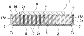
図1および図2において、液冷式冷却装置(1)は、頂壁(2a)、底壁(2b)および周壁(2c)を有するアルミニウム製ケーシング(2)と、ケーシング(2)に固定されたアルミニウム製放熱器(3)とを備えており、ケーシング(2)の頂壁(2a)および底壁(2b)うちのいずれか一方の第1壁、ここでは頂壁(2a)の外面が発熱体取付面(4)となされている。 In FIGS. 1 and 2, the liquid-cooled cooling device (1) is fixed to an aluminum casing (2) having a top wall (2a), a bottom wall (2b) and a peripheral wall (2c), and a casing (2). It is equipped with an aluminum radiator (3), and the first wall of either the top wall (2a) or the bottom wall (2b) of the casing (2), here the outer surface of the top wall (2a). It is the heating element mounting surface (4).
ケーシング(2)は、底壁(2b)および周壁(2c)を構成する上方に開口した箱状のアルミニウム製下構成部材(5)と、下構成部材(5)の周壁(2c)を構成する部分の上端部にろう材により接合され(以下、ろう付という)、かつ頂壁(2a)を構成する板状のアルミニウム製上構成部材(6)とよりなる。ケーシング(2)の下構成部材(5)は、アルミニウム板にプレス加工を施すことにより形成されてものであり、その結果ケーシング(2)の頂壁(2a)および底壁(2b)うちのいずれか他方の第2壁、ここでは底壁(2b)と周壁(2c)との連接部(7)の内側面(7a)には丸みがついている。 The casing (2) constitutes a box-shaped aluminum lower component (5) that opens upward to form the bottom wall (2b) and the peripheral wall (2c), and the peripheral wall (2c) of the lower component (5). It is joined to the upper end of the portion by a brazing material (hereinafter referred to as brazing), and is composed of a plate-shaped aluminum upper component (6) constituting the top wall (2a). The lower component (5) of the casing (2) is formed by pressing an aluminum plate, and as a result, either the top wall (2a) or the bottom wall (2b) of the casing (2) is formed. The other second wall, here the inner surface (7a) of the connecting portion (7) between the bottom wall (2b) and the peripheral wall (2c), is rounded.
ケーシング(2)内には、冷却液がケーシング(2)の長手方向の片側(後側)から他側(前側)に流れる冷却液流路(8)と、冷却液流路(8)よりも上流側(後側)に位置しかつ冷却液が流入する入口ヘッダ部(9)と、冷却液流路(8)よりも下流側(前側)に位置しかつ冷却液が流出する出口ヘッダ部(11)とが設けられている。 In the casing (2), the coolant flow path (8) in which the coolant flows from one side (rear side) in the longitudinal direction of the casing (2) to the other side (front side), and the coolant flow path (8) An inlet header (9) located on the upstream side (rear side) and into which the coolant flows, and an outlet header (9) located on the downstream side (front side) of the coolant flow path (8) and from which the coolant flows out. 11) and are provided.
ケーシング(2)の周壁(2c)の後側部分の左右方向中央部に、入口ヘッダ部(9)に通じる冷却液入口(12)が設けられ、ケーシング(2)の周壁(2c)の前側部分の左右方向中央部に、出口ヘッダ部(11)に通じる冷却液出口(13)が設けられている。ケーシング(2)の周壁(2c)に、冷却液入口(12)に通じるとともに入口ヘッダ部(9)内に冷却液を送り込むアルミニウム製入口パイプ(14)と、冷却液出口(13)に通じるとともに出口ヘッダ部(11)内から冷却液を送り出すアルミニウム製出口パイプ(15)とがろう付されている。 A coolant inlet (12) leading to the inlet header (9) is provided at the center in the left-right direction of the rear portion of the peripheral wall (2c) of the casing (2), and the front portion of the peripheral wall (2c) of the casing (2). A coolant outlet (13) leading to the outlet header portion (11) is provided at the central portion in the left-right direction of the above. The peripheral wall (2c) of the casing (2) is connected to the coolant inlet (12) and the aluminum inlet pipe (14) that sends the coolant into the inlet header (9), and the coolant outlet (13). The aluminum outlet pipe (15) that sends out the coolant from the outlet header (11) is brazed.
図3に示すように、放熱器(3)は、放熱基板(16)と、放熱基板(16)の下面に下方突出状にかつ千鳥配置状に一体に設けられてケーシング(2)内の全体に点在する横断面円形の複数のピン状フィン(17)(17A)とからなる。放熱基板(16)は、ケーシング(2)の上構成部材(6)、すなわち頂壁(2a)を兼ねており、その下面周縁部が下構成部材(5)の周壁上端にろう付されている。放熱基板(16)の上面が発熱体取付面(4)となっており、IGBTなどのパワーデバイスや、IGBTが制御回路と一体化されて同一パッケージに収納されたIGBTモジュールや、IGBTモジュールにさらに保護回路が一体化されて同一パッケージに収納されたインテリジェントパワーモジュールなどからなる発熱体(P)が、絶縁部材(図示略)を介して発熱体取付面(4)に取り付けられる。 As shown in FIG. 3, the radiator (3) is integrally provided on the lower surface of the heat radiating substrate (16) in a downwardly protruding shape and in a staggered arrangement, and the entire inside of the casing (2). It consists of a plurality of pin-shaped fins (17) (17A) having a circular cross section scattered around the surface. The heat radiating substrate (16) also serves as the upper component (6) of the casing (2), that is, the top wall (2a), and the lower peripheral edge thereof is brazed to the upper end of the peripheral wall of the lower component (5). .. The upper surface of the heat dissipation board (16) is the heating element mounting surface (4), and it can be added to power devices such as IGBTs, IGBT modules in which the IGBT is integrated with the control circuit and housed in the same package, and IGBT modules. A heating element (P) composed of an intelligent power module or the like in which a protection circuit is integrated and housed in the same package is attached to a heating element mounting surface (4) via an insulating member (not shown).
図4に示すように、放熱器の全フィン(17)(17A)のうち、少なくとも一部のフィン(17A)の一部がケーシング(2)の底壁(2b)と周壁(2c)との連接部(7)の内側面(7a)の範囲内に位置している。ケーシング(2)の底壁(2b)と周壁(2c)との連接部(7)の内側面(7a)の範囲内に位置しているフィン(17A)の放熱基板(16)からの突出高さをH、頂壁(2a)内面(放熱基板(16)内面)と、連接部(7)の内側面(7a)における頂壁(2a)側端部との距離をLとした場合、H≦Lになっている。また、放熱器(3)の全フィン(17)(17A)のうち、一部がケーシング(2)の底壁(2b)と周壁(2c)との連接部(7)の内側面(7a)の範囲内に位置しているフィン(17A)の放熱基板(16)からの突出高さHは、連接部(7)の内側面(7a)の範囲外に位置している他のフィン(17)の放熱基板(16)からの突出高さの1/2以上になっていることが好ましい。前記他のフィン(17)の高さはすべて等しく、その先端はケーシング(2)の底壁(2b)内面にろう付されていることが好ましいが、これに限定されるものではない。 As shown in FIG. 4, of all the fins (17) (17A) of the radiator, at least a part of the fins (17A) is formed between the bottom wall (2b) and the peripheral wall (2c) of the casing (2). It is located within the range of the inner surface (7a) of the connecting part (7). The height of protrusion of the fin (17A) from the heat dissipation substrate (16) located within the range of the inner surface (7a) of the connecting portion (7) between the bottom wall (2b) of the casing (2) and the peripheral wall (2c). Let H be the distance between the inner surface of the top wall (2a) (the inner surface of the heat dissipation substrate (16)) and the side end of the top wall (2a) on the inner surface (7a) of the connecting portion (7). ≤L. In addition, of all the fins (17) (17A) of the radiator (3), a part is the inner surface (7a) of the connecting portion (7) between the bottom wall (2b) of the casing (2) and the peripheral wall (2c). The protrusion height H of the fin (17A) located within the range of the heat radiation substrate (16) is the other fin (17) located outside the range of the inner surface (7a) of the connecting portion (7). ) Is preferably 1/2 or more of the protruding height from the heat radiating substrate (16). It is preferred, but not limited to, that the other fins (17) are all of equal height and their tips are brazed to the inner surface of the bottom wall (2b) of the casing (2).
上述した実施形態においては、横断面円形のピン状フィン(17)(17A)が用いられているが、これに限定されるものではなく、横断面形状が菱形や方形のピン状フィンが用いられることもある。 In the above-described embodiment, pin-shaped fins (17) (17A) having a circular cross section are used, but the present invention is not limited to this, and pin-shaped fins having a rhombic or square cross section are used. Sometimes.
上記構成の液冷式冷却装置(1)において、入口パイプ(14)から冷却液入口(12)を通って入口ヘッダ部(9)内に流入した冷却液は、放熱器(3)の冷却液流路(8)内の隣り合う放熱フィン(17)(17A)間を通って前方に流れる。冷却液流路(8)を前方に流れた冷却液は、出口ヘッダ部(11)内に入り、冷却液出口(13)を通って出口パイプ(15)に送り出される。発熱体(P)から発せられる熱は、放熱器(3)の放熱基板(16)および放熱フィン(17)(17A)を経て冷却液流路(8)内を流れる冷却液に放熱され、発熱体(P)が冷却される。 In the liquid-cooled cooling device (1) having the above configuration, the coolant flowing from the inlet pipe (14) through the coolant inlet (12) into the inlet header portion (9) is the coolant of the radiator (3). It flows forward through between adjacent heat sink fins (17) (17A) in the flow path (8). The coolant flowing forward through the coolant flow path (8) enters the outlet header portion (11) and is sent out to the outlet pipe (15) through the coolant outlet (13). The heat generated from the heating element (P) is dissipated to the cooling liquid flowing in the coolant flow path (8) via the heat radiating substrate (16) and the heat radiating fins (17) (17A) of the radiator (3), and generates heat. The body (P) is cooled.
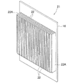
図5〜図7はこの発明による液冷式冷却装置の他の実施形態を示す。 5 to 7 show another embodiment of the liquid-cooled cooling device according to the present invention.
図5および図6に示すように、液冷式冷却装置(20)のケーシング(2)の上構成部材(6)を兼ねる放熱器(21)は、放熱基板(16)と、放熱基板(16)の下面に下方突出状に一体に設けられ、かつ前後方向に延びる複数のプレート状フィン(22)(22A)とからなる。全フィン(22)(22A)は左右方向に間隔をおいて並列状に設けられており、全フィン(22)(22A)の並び方向の両端に位置するフィン(22A)の少なくとも一部がケーシング(2)の底壁(2b)と周壁(2c)との連接部(7)の内側面(7a)の範囲内に位置している。 As shown in FIGS. 5 and 6, the radiator (21) that also serves as the upper component (6) of the casing (2) of the liquid-cooled cooling device (20) includes a heat radiating board (16) and a heat radiating board (16). ), It is composed of a plurality of plate-shaped fins (22) (22A) that are integrally provided on the lower surface of the) in a downward projecting manner and extend in the front-rear direction. All fins (22) (22A) are provided in parallel at intervals in the left-right direction, and at least a part of fins (22A) located at both ends in the arrangement direction of all fins (22) (22A) is casing. It is located within the range of the inner surface (7a) of the connecting portion (7) between the bottom wall (2b) and the peripheral wall (2c) of (2).
図7に示すように、少なくとも一部がケーシング(2)の底壁(2b)と周壁(2c)との連接部(7)の内側面(7a)の範囲内に位置しているフィン(22A)の放熱基板(16)からの突出高さをH、頂壁(2a)内面(放熱基板(16)内面)と、連接部(7)の内側面における頂壁(2a)側端部との距離をLとした場合、H≦Lになっている。また、放熱器(21)の全フィン(22)(22A)のうち、少なくとも一部がケーシング(2)の底壁(2b)と周壁(2c)との連接部(7)の内側面(7a)の範囲内に位置しているフィン(22A)の放熱基板(16)からの突出高さHは、連接部(7)の内側面(7a)の範囲外に位置している他のフィン(22)の放熱基板(16)からの突出高さの1/2以上になっていることが好ましい。前記他のフィン(22)の高さはすべて等しく、その先端はケーシング(2)の底壁(2b)内面にろう付されていることが好ましいが、これに限定されるものではない。 As shown in FIG. 7, at least a part of the fin (22A) is located within the range of the inner surface (7a) of the connecting portion (7) between the bottom wall (2b) of the casing (2) and the peripheral wall (2c). The height of protrusion from the heat radiating board (16) is H, and the inner surface of the top wall (2a) (inner surface of the heat radiating board (16)) and the side end of the top wall (2a) on the inner surface of the connecting portion (7). When the distance is L, H ≦ L. Further, of all the fins (22) and (22A) of the radiator (21), at least a part is the inner surface (7a) of the connecting portion (7) between the bottom wall (2b) of the casing (2) and the peripheral wall (2c). The protrusion height H of the fin (22A) located within the range of) from the heat dissipation substrate (16) is the other fin (7a) located outside the range of the inner surface (7a) of the connecting portion (7). It is preferable that the height of the protrusion from the heat radiating substrate (16) of 22) is halved or more. It is preferred, but not limited to, that the other fins (22) are all of equal height and their tips are brazed to the inner surface of the bottom wall (2b) of the casing (2).
その他の構成は、図1〜図4に示す液冷式冷却装置(1)と同様である。 Other configurations are the same as those of the liquid-cooled cooling device (1) shown in FIGS. 1 to 4.
上記構成の液冷式冷却装置(1)において、入口パイプ(14)から冷却液入口(12)を通って入口ヘッダ部(9)内に流入した冷却液は、放熱器(21)の冷却液流路(8)内の隣り合う放熱フィン(22)(22A)間を通って前方に流れる。冷却液流路(8)を前方に流れた冷却液は、出口ヘッダ部(11)内に入り、冷却液出口(13)を通って出口パイプ(15)に送り出される。発熱体(P)から発せられる熱は、放熱器(3)の放熱基板(16)および放熱フィン(22)(22A)を経て冷却液流路(8)内を流れる冷却液に放熱され、発熱体(P)が冷却される。 In the liquid-cooled cooling device (1) having the above configuration, the coolant flowing from the inlet pipe (14) through the coolant inlet (12) into the inlet header portion (9) is the coolant of the radiator (21). It flows forward through between adjacent heat sink fins (22) (22A) in the flow path (8). The coolant flowing forward through the coolant flow path (8) enters the outlet header portion (11) and is sent out to the outlet pipe (15) through the coolant outlet (13). The heat generated from the heating element (P) is dissipated to the coolant flowing in the coolant flow path (8) via the heat sink (16) and the heat radiation fins (22) (22A) of the radiator (3), and generates heat. The body (P) is cooled.
この発明による液冷式冷却装置は、電気自動車、ハイブリッド自動車、電車などに搭載される電力変換装置に用いられるIGBTなどのパワーデバイスを冷却するのに好適に用いられる。 The liquid-cooled cooling device according to the present invention is suitably used for cooling a power device such as an IGBT used in a power conversion device mounted on an electric vehicle, a hybrid vehicle, a train, or the like.
(1)(20):液冷式冷却装置
(2):ケーシング
(2a):頂壁(第1壁)
(2b):底壁(第2壁)
(2c):周壁
(3)(21):放熱器
(4):発熱体取付面
(7):連接部
(7a):内側面
(8):冷却液流路
(16):放熱基板
(17)(17A):ピン状のフィン
(22)(22A):プレート状のフィン
(1) (20): Liquid-cooled cooling device
(2): Casing
(2a): Top wall (first wall)
(2b): Bottom wall (second wall)
(2c): Circumferential wall
(3) (21): Dissipator
(4): Heating element mounting surface
(7): Connecting part
(7a): Inner surface
(8): Coolant flow path
(16): Heat dissipation board
(17) (17A): Pin-shaped fins
(22) (22A): Plate-shaped fins
Claims (5)
放熱器の全フィンのうち、少なくとも一部が前記第2壁と周壁との連接部内側面の範囲内に位置するフィンの放熱基板からの突出高さをH、前記第1壁内面と、前記第2壁と周壁との連接部内側面における前記第1壁側端部との距離をLとした場合、H≦Lになっている液冷式冷却装置。 A casing having a top wall, a bottom wall and a peripheral wall and having a cooling liquid flow path inside, and a radiator fixed to the casing are provided, and either the top wall or the bottom wall of the casing is provided. The outer surface of the first wall of the casing serves as the heating element mounting surface, and the inner surface of the connecting portion between the second wall and the peripheral wall of either the top wall or the bottom wall of the casing is rounded, and the radiator is a radiator of the casing. A liquid-cooled cooling device including a heat-dissipating substrate that serves as the first wall and is joined to the peripheral wall of the casing, and a plurality of fins that are provided on one side of the heat-dissipating substrate and project toward the coolant flow path side.
Of all the fins of the radiator, at least a part of the fins is located within the range of the inner surface of the connecting portion between the second wall and the peripheral wall. A liquid-cooled cooling device in which H ≦ L, where L is the distance between the inner side surface of the connecting portion between the two walls and the peripheral wall and the end portion on the first wall side.
All the fins of the radiator are plate-shaped, and all the fins are provided in parallel with each other spaced apart from each other. The liquid-cooled cooling device according to any one of claims 1 to 3, which is located within the range of the inner surface of the connecting portion between the surface and the peripheral wall.
Priority Applications (1)
| Application Number | Priority Date | Filing Date | Title |
|---|---|---|---|
| JP2017247594A JP6932632B2 (en) | 2017-12-25 | 2017-12-25 | Liquid cooling system |
Applications Claiming Priority (1)
| Application Number | Priority Date | Filing Date | Title |
|---|---|---|---|
| JP2017247594A JP6932632B2 (en) | 2017-12-25 | 2017-12-25 | Liquid cooling system |
Publications (2)
| Publication Number | Publication Date |
|---|---|
| JP2019114682A JP2019114682A (en) | 2019-07-11 |
| JP6932632B2 true JP6932632B2 (en) | 2021-09-08 |
Family
ID=67221614
Family Applications (1)
| Application Number | Title | Priority Date | Filing Date |
|---|---|---|---|
| JP2017247594A Active JP6932632B2 (en) | 2017-12-25 | 2017-12-25 | Liquid cooling system |
Country Status (1)
| Country | Link |
|---|---|
| JP (1) | JP6932632B2 (en) |
Families Citing this family (3)
| Publication number | Priority date | Publication date | Assignee | Title |
|---|---|---|---|---|
| US20240151481A1 (en) * | 2019-11-12 | 2024-05-09 | Toyota Jidosha Kabushiki Kaisha | Cooler and manufacturing method thereof |
| JP6997229B2 (en) * | 2020-01-09 | 2022-01-17 | 株式会社フジクラ | Cold plate |
| KR20210098786A (en) * | 2020-02-03 | 2021-08-11 | 엘에스일렉트릭(주) | Cooling plate and method of product the same |
Family Cites Families (5)
| Publication number | Priority date | Publication date | Assignee | Title |
|---|---|---|---|---|
| JP2003324173A (en) * | 2002-05-02 | 2003-11-14 | Nissan Motor Co Ltd | Cooling device for semiconductor device |
| US7215545B1 (en) * | 2003-05-01 | 2007-05-08 | Saeed Moghaddam | Liquid cooled diamond bearing heat sink |
| JP4797077B2 (en) * | 2009-02-18 | 2011-10-19 | 株式会社日立製作所 | Semiconductor power module, power converter, and method for manufacturing semiconductor power module |
| JP2015126107A (en) * | 2013-12-26 | 2015-07-06 | 株式会社豊田自動織機 | Electronic apparatus |
| JP6482954B2 (en) * | 2015-06-02 | 2019-03-13 | 昭和電工株式会社 | Liquid cooling system |
-
2017
- 2017-12-25 JP JP2017247594A patent/JP6932632B2/en active Active
Also Published As
| Publication number | Publication date |
|---|---|
| JP2019114682A (en) | 2019-07-11 |
Similar Documents
| Publication | Publication Date | Title |
|---|---|---|
| JP6463505B2 (en) | Semiconductor device, inverter device and automobile | |
| JP6482954B2 (en) | Liquid cooling system | |
| JP6247090B2 (en) | Liquid cooling type cooling device and manufacturing method of radiator for liquid cooling type cooling device | |
| CN105308742B (en) | Manufacturing method of cooler for semiconductor component, cooler for semiconductor component, semiconductor component, and electric drive vehicle | |
| JP6349161B2 (en) | Liquid cooling system | |
| CN102569222B (en) | Cooling device and power conversion device including the same | |
| JP6546521B2 (en) | Liquid cooling system | |
| CN204792762U (en) | Liquid cooling formula cooling device | |
| JP6534873B2 (en) | Liquid cooling system | |
| JP6279980B2 (en) | Liquid cooling system | |
| JP6735664B2 (en) | Radiator for liquid cooling type cooling device and manufacturing method thereof | |
| JP6738226B2 (en) | Cooling system | |
| JP6482955B2 (en) | Liquid cooling system | |
| JP2016219572A (en) | Liquid cooling cooler | |
| JP6554406B2 (en) | Liquid-cooled cooler | |
| JP7091103B2 (en) | Cooling system | |
| JP6469521B2 (en) | Liquid cooling system | |
| JP6932632B2 (en) | Liquid cooling system | |
| JP6623120B2 (en) | Liquid cooling system | |
| JP2016004805A (en) | Liquid cooling type cooling device | |
| JP6917230B2 (en) | Dissipator and liquid-cooled cooling device using it | |
| JP2008278576A (en) | Power semiconductor element cooling device | |
| CN206388696U (en) | Liquid-cooled-type cooling device | |
| JP2010093034A (en) | Cooling device for electronic component | |
| JP2018207017A (en) | Semiconductor device |
Legal Events
| Date | Code | Title | Description |
|---|---|---|---|
| A621 | Written request for application examination |
Free format text: JAPANESE INTERMEDIATE CODE: A621 Effective date: 20200925 |
|
| TRDD | Decision of grant or rejection written | ||
| A977 | Report on retrieval |
Free format text: JAPANESE INTERMEDIATE CODE: A971007 Effective date: 20210721 |
|
| A01 | Written decision to grant a patent or to grant a registration (utility model) |
Free format text: JAPANESE INTERMEDIATE CODE: A01 Effective date: 20210727 |
|
| A61 | First payment of annual fees (during grant procedure) |
Free format text: JAPANESE INTERMEDIATE CODE: A61 Effective date: 20210818 |
|
| R150 | Certificate of patent or registration of utility model |
Ref document number: 6932632 Country of ref document: JP Free format text: JAPANESE INTERMEDIATE CODE: R150 |
|
| RD02 | Notification of acceptance of power of attorney |
Free format text: JAPANESE INTERMEDIATE CODE: R3D02 |
|
| S111 | Request for change of ownership or part of ownership |
Free format text: JAPANESE INTERMEDIATE CODE: R313111 |
|
| R350 | Written notification of registration of transfer |
Free format text: JAPANESE INTERMEDIATE CODE: R350 |
|
| S531 | Written request for registration of change of domicile |
Free format text: JAPANESE INTERMEDIATE CODE: R313531 |
|
| R350 | Written notification of registration of transfer |
Free format text: JAPANESE INTERMEDIATE CODE: R350 |