JP6931518B2 - Single-sided protective polarizing film, polarizing film with adhesive layer, image display device and its continuous manufacturing method - Google Patents
Single-sided protective polarizing film, polarizing film with adhesive layer, image display device and its continuous manufacturing method Download PDFInfo
- Publication number
- JP6931518B2 JP6931518B2 JP2015189281A JP2015189281A JP6931518B2 JP 6931518 B2 JP6931518 B2 JP 6931518B2 JP 2015189281 A JP2015189281 A JP 2015189281A JP 2015189281 A JP2015189281 A JP 2015189281A JP 6931518 B2 JP6931518 B2 JP 6931518B2
- Authority
- JP
- Japan
- Prior art keywords
- polarizing film
- adhesive layer
- protective
- meth
- film
- Prior art date
- Legal status (The legal status is an assumption and is not a legal conclusion. Google has not performed a legal analysis and makes no representation as to the accuracy of the status listed.)
- Active
Links
Images


Description
本発明は、偏光子の片面にのみ保護フィルムが設けられた片保護偏光フィルムおよび当該片保護偏光フィルムと粘着剤層を有する粘着剤層付偏光フィルムに関する。前記片保護偏光フィルムおよび粘着剤層付偏光フィルムはこれ単独で、またはこれを積層した光学フィルムとして液晶表示装置(LCD)、有機EL表示装置などの画像表示装置を形成しうる。 The present invention relates to a single protective polarizing film in which a protective film is provided on only one side of a polarizing element, and a polarizing film with an adhesive layer having the single protective polarizing film and an adhesive layer. The one-sided protective polarizing film and the polarizing film with an adhesive layer can form an image display device such as a liquid crystal display device (LCD) or an organic EL display device alone or as an optical film obtained by laminating them.
液晶表示装置には、その画像形成方式から液晶パネル表面を形成するガラス基板の両側に偏光フィルムを配置することが必要不可欠である。偏光フィルムは、一般的には、ポリビニルアルコール系フィルムとヨウ素等の二色性材料からなる偏光子の片面または両面に、保護フィルムをポリビニルアルコール系接着剤等により貼り合わせたものが用いられている。 In a liquid crystal display device, it is indispensable to arrange polarizing films on both sides of a glass substrate forming a liquid crystal panel surface according to the image forming method. The polarizing film is generally a film in which a protective film is attached to one side or both sides of a polyvinyl alcohol-based film and a polarizing element made of a dichroic material such as iodine with a polyvinyl alcohol-based adhesive or the like. ..
前記偏光フィルムを液晶セル等に貼着する際には、通常、粘着剤が使用される。また、偏光フィルムを瞬時に固定できること、偏光フィルムを固着させるのに乾燥工程を必要としないこと等のメリットを有することから、粘着剤は、偏光フィルムの片面に予め粘着剤層として設けられている。即ち、偏光フィルムの貼着には粘着剤層付偏光フィルムが一般的に用いられる。 When the polarizing film is attached to a liquid crystal cell or the like, an adhesive is usually used. Further, since the polarizing film can be fixed instantly and there is no need for a drying step to fix the polarizing film, the pressure-sensitive adhesive is provided in advance as a pressure-sensitive adhesive layer on one side of the polarizing film. .. That is, a polarizing film with an adhesive layer is generally used for attaching the polarizing film.
また、偏光フィルムや粘着剤層付偏光フィルムは、熱衝撃(例えば、−30℃と80℃の温度条件を繰り返すヒートショック試験や100℃の高温下試験)の過酷な環境下では偏光子の収縮応力の変化によって、偏光子の吸収軸方向の全体にクラック(貫通クラック)が生じやすい問題がある。即ち、粘着剤層付偏光フィルムは、前記過酷な環境下における熱衝撃による耐久性が十分ではなかった。特に、薄型化の観点から、偏光子の片面にのみ保護フィルムを設けた片保護偏光フィルムを用いた粘着剤層付偏光フィルムでは、前記熱衝撃による耐久性が不十分であった。また、前記熱衝撃により生じる貫通クラックは、偏光フィルムのサイズが大きくなった場合に発生しやすいものであった。 Further, the polarizing film and the polarizing film with an adhesive layer shrink the polarizer under a harsh environment of thermal shock (for example, a heat shock test in which temperature conditions of -30 ° C and 80 ° C are repeated and a high temperature test of 100 ° C). There is a problem that cracks (through cracks) are likely to occur in the entire direction of the absorber in the absorption axis due to changes in stress. That is, the polarizing film with an adhesive layer did not have sufficient durability due to thermal shock in the harsh environment. In particular, from the viewpoint of thinning, a polarizing film with an adhesive layer using a single protective polarizing film provided with a protective film on only one side of the polarizer has insufficient durability due to the thermal shock. Further, the through cracks generated by the thermal shock are likely to occur when the size of the polarizing film is increased.
前記貫通クラックの発生の抑制のために、例えば、片保護偏光フィルムに引張弾性率100MPa以上の保護層を設け、さらに当該保護層に粘着剤層を設けた粘着剤層付偏光フィルムが提案されている(特許文献1)。また、厚さ25μm以下の偏光子の片面に硬化型樹脂組成物の硬化物からなる保護層を有し、偏光子のもう一方の片面に保護フィルムを有し、前記保護層の外側に粘着剤層を有する粘着剤層付偏光フィルムが提案されている(特許文献2)。前記特許文献1、2に記載の粘着剤層付偏光フィルムは、貫通クラックの発生の抑制の点からは有効である。また、薄型化は偏光子についても行われており、例えば、単体透過率、偏光度の光学特性を制御した、高い配向性を示す薄型偏光子が提案されている(特許文献3)。
In order to suppress the occurrence of through cracks, for example, a polarizing film with an adhesive layer is proposed in which a protective layer having a tensile elastic modulus of 100 MPa or more is provided on a single protective polarizing film, and an adhesive layer is further provided on the protective layer. (Patent Document 1). Further, one side of a polarizer having a thickness of 25 μm or less has a protective layer made of a cured product of a curable resin composition, the other side of the polarizer has a protective film, and an adhesive is provided on the outside of the protective layer. A polarizing film with an adhesive layer having a layer has been proposed (Patent Document 2). The polarizing film with an adhesive layer described in
特許文献1、2では、偏光子の片面にのみ保護フィルムを有する片保護偏光フィルムを用いることで薄型化を図るとともに、他方では、保護層を設けることにより、片保護偏光フィルムを用いることにより生じる偏光子の吸収軸方向への貫通クラックの発生を抑えている。
In
一方、薄型化は偏光子についても行われている。偏光フィルムまたは粘着剤層付偏光フィルムに用いる偏光子を薄くした場合には、偏光子の収縮応力の変化が小さくなる。そのため、薄型化した偏光子によれば、前記貫通クラックの発生を抑制することができることが分かった。 On the other hand, the thinning is also performed for the polarizer. When the polarizing element used for the polarizing film or the polarizing film with an adhesive layer is thinned, the change in shrinkage stress of the polarizing element becomes small. Therefore, it was found that the thinned polarizer can suppress the occurrence of the through crack.
しかし、前記貫通クラックの発生が抑制された片保護偏光フィルムまたはそれを用いた粘着剤層付偏光フィルムにおいて、特許文献3のように光学特性を制御し、かつ偏光子を薄くした場合(例えば、厚み10μm以下にした場合)には、片保護偏光フィルムまたはそれを用いた粘着剤層付偏光フィルムに機械衝撃が負荷されたとき(偏光子側に凸折れによる負荷がかかる場合を含む)に、偏光子の吸収軸方向に部分的に極細のスリット(以下、ナノスリットともいう)が発生することが分かった。前記ナノスリットは、偏光フィルムのサイズに無関係に生じることも分かった。さらには、前記ナノスリットは、偏光子の両面に保護フィルムを有する両保護偏光フィルムを用いた場合には生じないことも分かった。また、偏光子に貫通クラックが生じた場合には、貫通クラックの周辺の応力が解放されるため、貫通クラックは隣接して生じることはないが、ナノスリットは単独で生じる他に、隣接して生じることが分かった。また、貫通クラックは、クラックが生じた偏光子の吸収軸方向に伸びる進行性を有しているが、ナノスリットは前記進行性のないことも分かった。このように、前記ナノスリットは、貫通クラックの発生が抑制された片保護偏光フィルムにおいて、偏光子を薄く、かつ、光学特性を所定の範囲に制御した場合に生じる新たな課題であり、従来知られていた前記貫通クラックとは異なる現象により生じる課題であることが分かった。 However, in a single-protective polarizing film in which the occurrence of through cracks is suppressed or a polarizing film with an adhesive layer using the same, when the optical characteristics are controlled and the polarizer is thinned (for example, as in Patent Document 3). When the thickness is 10 μm or less), when a mechanical impact is applied to the one-sided protective polarizing film or the polarizing film with an adhesive layer using it (including the case where a load due to convex fold is applied to the polarizer side). It was found that extra-fine slits (hereinafter, also referred to as nanoslits) were partially generated in the direction of the absorber's absorption axis. It was also found that the nanoslits occur regardless of the size of the polarizing film. Furthermore, it was also found that the nanoslit does not occur when both protective polarizing films having protective films on both sides of the polarizer are used. Further, when a through crack occurs in the polarizer, the stress around the through crack is released, so that the through crack does not occur adjacently, but the nanoslits occur independently or adjacently. It turned out to occur. It was also found that the penetrating crack has a progressive property of extending in the absorption axis direction of the polarizing element in which the crack is generated, but the nanoslit does not have the progressive property. As described above, the nanoslit is a new problem that occurs when the polarizer is thin and the optical characteristics are controlled within a predetermined range in the single-protection polarizing film in which the occurrence of through cracks is suppressed. It was found that this is a problem caused by a phenomenon different from that of the through crack.
また、前記ナノスリットは極細であるため、通常の環境下では検出できない。従って、仮に、偏光子にナノスリットが発生していたとしても、片保護偏光フィルムおよびそれを用いた粘着剤層付偏光フィルムの光抜けによる欠陥を確認することは一見したのみでは困難である。すなわち、通常、片保護偏光フィルムは長尺フィルム状に作製され、自動的光学検査にて欠陥検査されるが、この欠陥検査でナノスリットを欠陥として検出することが困難である。前記ナノスリットによる欠陥は、片保護偏光フィルムまたは粘着剤層付偏光フィルムが画像表示パネルのガラス基板等に貼り合わされたうえで加熱環境下におかれた場合に、ナノスリットが幅方向に広がることで検出可能(例えば、前記光抜けの有無)になることも分かった。 Moreover, since the nanoslit is extremely fine, it cannot be detected under a normal environment. Therefore, even if nanoslits are generated in the polarizing element, it is difficult at first glance to confirm defects due to light leakage of the single-protective polarizing film and the polarizing film with an adhesive layer using the same. That is, usually, the one-sided protective polarizing film is produced in the form of a long film and is inspected for defects by automatic optical inspection, but it is difficult to detect nanoslits as defects by this defect inspection. The defect caused by the nanoslit is that the nanoslit expands in the width direction when a single protective polarizing film or a polarizing film with an adhesive layer is attached to a glass substrate or the like of an image display panel and then placed in a heating environment. It was also found that it becomes detectable (for example, the presence or absence of the light leakage).
よって、薄型偏光子を用いた片保護偏光フィルムまたはそれを用いた粘着剤層付偏光フィルムにおいては、貫通クラックだけでなく、ナノスリットによる欠陥も抑制しておくことが望まれる。さらには片保護偏光フィルムまたはそれを用いた粘着剤層付偏光フィルムにおいては、両側に保護フィルムを有する両保護構成の偏光フィルムと比較して薄いため取り扱い時に偏光フィルムに折れや破断が発生しやすい。そのため、取り扱い時には、偏光フィルムまたはそれを用いた粘着剤層付偏光フィルムがカールしていないことが望まれる。また、片保護偏光フィルムに固化または硬化によって保護層を設けた保護層付き片保護偏光フィルムにおいては、保護層の形成時に、保護層を形成する材料の収縮が起こり偏光子と保護層との間に応力がたまりやすく、カールが発生しやすい。そのため片保護偏光フィルムまたはそれを用いた粘着剤層付偏光フィルムにおいては、取り扱い性の観点からカールが発生しないことが望まれる。 Therefore, in a single-protective polarizing film using a thin polarizing element or a polarizing film with an adhesive layer using the same, it is desired to suppress not only through cracks but also defects due to nanoslits. Furthermore, the one-sided protective polarizing film or the polarizing film with an adhesive layer using the same is thinner than the polarizing film having both protective configurations having protective films on both sides, so that the polarizing film is liable to break or break during handling. .. Therefore, it is desirable that the polarizing film or the polarizing film with an adhesive layer using the polarizing film is not curled at the time of handling. Further, in a single protective polarizing film with a protective layer in which a protective layer is provided by solidification or curing of the single protective polarizing film, shrinkage of the material forming the protective layer occurs at the time of forming the protective layer, and between the polarizer and the protective layer. Stress tends to accumulate in the film, and curl tends to occur. Therefore, it is desired that curl does not occur in the one-sided protective polarizing film or the polarizing film with an adhesive layer using the same protective polarizing film from the viewpoint of handleability.
本発明は、薄型偏光子の片面にのみ保護フィルムを有する片保護偏光フィルムであって、前記偏光子が所定の光学特性を有し、かつ貫通クラックおよびナノスリットによる欠陥およびカールの発生を抑制することができる片保護偏光フィルムを提供することを目的とする。また、本発明は、前記片保護偏光フィルムと粘着剤層を有する粘着剤層付偏光フィルムを提供することを目的とする。 The present invention is a single-sided protective polarizing film having a protective film on only one side of a thin polarizing element, wherein the polarizer has predetermined optical characteristics and suppresses the occurrence of defects and curls due to through cracks and nanoslits. It is an object of the present invention to provide a single protective polarizing film capable of providing a single protective polarizing film. Another object of the present invention is to provide a polarizing film with an adhesive layer having the single protective polarizing film and an adhesive layer.
また本発明は、前記片保護偏光フィルムまたは前記粘着剤層付偏光フィルムを有する画像表示装置、さらにはその連続製造方法を提供することを目的とする。 Another object of the present invention is to provide an image display device having the one-sided protective polarizing film or the polarizing film with an adhesive layer, and a method for continuously producing the same.
本願発明者らは、鋭意検討の結果、下記の片保護偏光フィルム、粘着剤層付偏光フィルム等により上記課題を解決し得ることを見出し、本発明に至った。 As a result of diligent studies, the inventors of the present application have found that the above problems can be solved by the following single-protective polarizing film, polarizing film with an adhesive layer, and the like, and have reached the present invention.
即ち本発明は、偏光子の片面にのみ保護フィルムを有する片保護偏光フィルムであって、
前記偏光子は、ポリビニルアルコール系樹脂を含有し、かつ、単体透過率T及び偏光度Pによって表される光学特性が、下記式
P>−(100.929T−42.4−1)×100(ただし、T<42.3)、又は、
P≧99.9(ただし、T≧42.3)の条件を満足するように構成されたものであり、
かつ、偏光子の厚みをX(μm)、透明樹脂層の厚さをY(μm)としたとき、
X≦12、
Y≦15、
0.15≦(Y/X)≦3、を満足することを特徴とする片保護偏光フィルム、に関する。
That is, the present invention is a single protective polarizing film having a protective film on only one side of the polarizer.
The polarizer contains a polyvinyl alcohol-based resin, and the optical characteristics represented by the simple substance transmittance T and the degree of polarization P are expressed by the following formula P>-(10 0.929T-42.4-1 ) × 100. (However, T <42.3) or
It is configured to satisfy the condition of P ≧ 99.9 (however, T ≧ 42.3).
And when the thickness of the polarizer is X (μm) and the thickness of the transparent resin layer is Y (μm),
X ≦ 12,
Y ≦ 15,
The present invention relates to a single protective polarizing film, which satisfies 0.15 ≦ (Y / X) ≦ 3.
前記片保護偏光フィルムにおいて、前記透明樹脂層は、80℃における圧縮弾性率が0.1GPa以上であることが好ましい。 In the one-sided protective polarizing film, the transparent resin layer preferably has a compressive elastic modulus of 0.1 GPa or more at 80 ° C.
前記片保護偏光フィルムにおいて、前記透明樹脂層は、紫外線硬化型アクリル系樹脂、紫外線硬化型エポキシ系樹脂、ウレタン系樹脂またはポリビニルアルコール系樹脂から形成されていることが好ましい。 In the one-sided protective polarizing film, the transparent resin layer is preferably formed of an ultraviolet curable acrylic resin, an ultraviolet curable epoxy resin, a urethane resin, or a polyvinyl alcohol resin.
前記片保護偏光フィルムにおいて、前記偏光子と前記保護フィルムとの間に接着剤層を有することが好ましい。前記接着剤層の厚みは、0.1μm以上5μm以下であることが好ましい。また、前記接着剤層は、80℃における圧縮弾性率が0.1GPa以上10GPa以下であることが好ましい。また、前記接着剤層は、紫外線硬化型アクリル系樹脂、紫外線硬化型エポキシ系樹脂、ウレタン系樹脂またはポリビニルアルコール系樹脂から形成されていることが好ましい。 In the single protective polarizing film, it is preferable to have an adhesive layer between the polarizer and the protective film. The thickness of the adhesive layer is preferably 0.1 μm or more and 5 μm or less. Further, the adhesive layer preferably has a compressive elastic modulus at 80 ° C. of 0.1 GPa or more and 10 GPa or less. Further, the adhesive layer is preferably formed of an ultraviolet curable acrylic resin, an ultraviolet curable epoxy resin, a urethane resin or a polyvinyl alcohol resin.
前記片保護偏光フィルムにおいて、前記保護フィルムが1枚の場合には、保護フィルムの厚みは10μm以上100μm以下であることが好ましい。 In the single protective polarizing film, when there is only one protective film, the thickness of the protective film is preferably 10 μm or more and 100 μm or less.
前記片保護偏光フィルムにおいて、前記保護フィルムが2枚である場合には、各保護フィルムの厚みは10μm以上であり、かつ保護フィルムの総厚みは100μm以下であり、各保護フィルムの間には接着剤層または粘着剤層を有するが好ましい。 In the single protective polarizing film, when the number of protective films is two, the thickness of each protective film is 10 μm or more, and the total thickness of the protective films is 100 μm or less, and the protective films are adhered to each other. It preferably has an agent layer or an adhesive layer.
前記片保護偏光フィルムにおいて、前記偏光子は、偏光子全量に対してホウ酸を25重量%以下で含有することが好ましい。 In the single-protective polarizing film, the polarizer preferably contains boric acid in an amount of 25% by weight or less based on the total amount of the polarizer.
また本発明は、前記片保護偏光フィルム、および粘着剤層を有することを特徴とする粘着剤層付偏光フィルム、に関する。 The present invention also relates to the one-sided protective polarizing film and a polarizing film with an adhesive layer, which comprises an adhesive layer.
前記粘着剤層付偏光フィルムにおいて、前記粘着剤層の厚みは、1μm以上40μm以下であることが好ましい。また前記粘着剤層は、23℃における貯蔵弾性率が1.0×10⁴Pa以上であることが好ましい。 In the polarizing film with an adhesive layer, the thickness of the adhesive layer is preferably 1 μm or more and 40 μm or less. The pressure-sensitive adhesive layer is preferably a storage modulus at 23 ° C. is 1.0 × 10 4 Pa or more.
前記粘着剤層付偏光フィルムは、前記片保護偏光フィルムの透明樹脂層に、前記粘着剤層が設けられている態様で用いることできる。また、前記粘着剤層付偏光フィルムは、前記片保護偏光フィルムの保護フィルムに、前記粘着剤層が設けられている態様で用いることができる。また、前記粘着剤層付偏光フィルムの粘着剤層にはセパレータを設けることができる。セパレータが設けられた粘着剤層付偏光フィルムは巻回体として用いることができる。 The polarizing film with an adhesive layer can be used in an embodiment in which the pressure-sensitive adhesive layer is provided on the transparent resin layer of the one-sided protective polarizing film. Further, the polarizing film with an adhesive layer can be used in a manner in which the pressure-sensitive adhesive layer is provided on the protective film of the one-sided protective polarizing film. Further, a separator may be provided on the pressure-sensitive adhesive layer of the polarizing film with the pressure-sensitive adhesive layer. A polarizing film with an adhesive layer provided with a separator can be used as a wound body.
また本発明は、前記片保護偏光フィルム、または前記粘着剤層付偏光フィルムを有する画像表示装置、に関する。 The present invention also relates to the one-sided protective polarizing film or an image display device having the pressure-sensitive adhesive layered polarizing film.
また本発明は、前記粘着剤層付偏光フィルムの巻回体から繰り出され、前記セパレータにより搬送された前記粘着剤層付偏光フィルムを、前記粘着剤層を介して画像表示パネルの表面に連続的に貼り合せる工程を含む画像表示装置の連続製造方法、に関する。 Further, in the present invention, the polarizing film with the pressure-sensitive adhesive layer, which is unwound from the wound body of the polarizing film with the pressure-sensitive adhesive layer and conveyed by the separator, is continuously applied to the surface of the image display panel via the pressure-sensitive adhesive layer. The present invention relates to a method for continuously manufacturing an image display device, which includes a step of bonding to.
本発明の片保護偏光フィルムおよび粘着剤層付偏光フィルムは、厚み12μm以下の偏光子を用いており、薄型化されている。また、前記厚み12μm以下の薄型の偏光子は、偏光子の厚みが大きい場合に比べて、熱衝撃により偏光子に加わる収縮応力の変化が小さいため、貫通クラックの発生を抑制することができる。 The single-protective polarizing film and the polarizing film with an adhesive layer of the present invention use a polarizer having a thickness of 12 μm or less, and are thinned. Further, in the thin polarizing element having a thickness of 12 μm or less, the change in contraction stress applied to the polarizer due to thermal shock is smaller than in the case where the thickness of the polarizer is large, so that the occurrence of through cracks can be suppressed.
一方、所定の光学特性を有する薄型の偏光子は、偏光子にナノスリットが発生しやすくなる。ナノスリットは、片保護偏光フィルムの製造工程、片保護偏光フィルムに粘着剤層を設ける粘着剤層付偏光フィルムの製造工程、粘着剤層付偏光フィルムを製造した後の各種工程において、前記片保護偏光フィルムまたはそれを用いた粘着剤層付偏光フィルムに対して機械衝撃が負荷されたときに生じると考えられ、熱衝撃により生じる貫通クラックとは異なるメカニズムにより生じると想定される。また、前記ナノスリットによる欠陥は、片保護偏光フィルムまたは粘着剤層付偏光フィルムが画像表示パネルのガラス基板等に貼り合わされたうえで加熱環境下におかれた場合に、ナノスリットが幅方向に広がることで検出可能(例えば、前記光抜けの有無)になる。 On the other hand, in a thin polarizer having predetermined optical characteristics, nanoslits are likely to occur in the polarizer. The nanoslit is used in the manufacturing process of a single protective polarizing film, the manufacturing process of a polarizing film with an adhesive layer for providing an adhesive layer on the single protective polarizing film, and various processes after manufacturing the polarizing film with an adhesive layer. It is considered that it occurs when a mechanical impact is applied to the polarizing film or the polarizing film with an adhesive layer using the polarizing film, and it is assumed that it is generated by a mechanism different from the through crack caused by the thermal impact. Further, the defect due to the nanoslit is caused by the nanoslit in the width direction when a single protective polarizing film or a polarizing film with an adhesive layer is attached to a glass substrate or the like of an image display panel and then placed in a heating environment. By spreading, it becomes detectable (for example, the presence or absence of the light leakage).
本発明の片保護偏光フィルムおよび粘着剤層付偏光フィルムでは、偏光子の他の片面(保護フィルムを有しない面)に、透明樹脂層を設けることで、仮に、透明樹脂層を設ける前の片保護偏光フィルムの状態の偏光子に前記ナノスリットが発生した場合にも、ナノスリットの幅方向への広がりによる欠陥の発生を抑えることができる。特に、80℃における圧縮弾性率が0.1GPa以上の透明樹脂層は有効である。 In the one-sided protective polarizing film and the polarizing film with an adhesive layer of the present invention, by providing a transparent resin layer on the other side of the polarizer (the side having no protective film), a piece before the transparent resin layer is provided. Even when the nanoslit is generated in the polarizer in the state of the protective polarizing film, it is possible to suppress the occurrence of defects due to the spread of the nanoslit in the width direction. In particular, a transparent resin layer having a compressive elastic modulus at 80 ° C. of 0.1 GPa or more is effective.
以上のように、本発明の片保護偏光フィルムおよびそれを用いた粘着剤層付偏光フィルムは、透明樹脂層を有することで、薄型化を満足しながら、かつ、偏光子に生じる貫通クラックおよびナノスリットによる欠陥を抑制することができる。 As described above, the single-protective polarizing film of the present invention and the polarizing film with an adhesive layer using the same have a transparent resin layer, so that the thinning can be satisfied, and through cracks and nanon appear in the polarizer. Defects due to slits can be suppressed.
また、本発明の片保護偏光フィルムおよび粘着剤層付偏光フィルムでは、薄型の偏光子の厚みX(μm)と、透明樹脂層の厚さをY(μm)は、X≦12、Y≦15、0.15≦(Y/X)≦3、を満足するように設計されており、偏光子に生じる貫通クラックおよびナノスリットによる欠陥を抑制することができる透明樹脂層を設けているにも拘わらず、カールの発生を抑えることができる。 Further, in the single-protective polarizing film and the polarizing film with an adhesive layer of the present invention, the thickness X (μm) of the thin polarizing element and the thickness Y (μm) of the transparent resin layer are X ≦ 12 and Y ≦ 15. , 0.15 ≦ (Y / X) ≦ 3, and despite the provision of a transparent resin layer that can suppress through-cracks and defects due to nanoslits that occur in the polarizer. However, the occurrence of curl can be suppressed.
以下に本発明の片保護偏光フィルム11および粘着剤層付偏光フィルム12を、図1、2を参照しながら説明する。片保護偏光フィルム10(透明樹脂層3のない場合)は、例えば、図1(A)に示すように、偏光子1の片面にのみ保護フィルム2を有する。偏光子1と保護フィルム2とは接着剤層2a(その他、粘着剤層、下塗り層(プライマー層)などの介在層)を介して積層されている。また図示していないが、片保護偏光フィルム10は、保護フィルム2に易接着層を設けたり活性化処理を施したりして、当該易接着層と接着剤層を積層することができる。本発明の片保護偏光フィルム11(透明樹脂層3付)は、図1に示すように、片保護偏光フィルム10において、前記偏光子1の他の片面(保護フィルム2を有しない面)に、透明樹脂層3が(直接)設けられている。また、図1(B)に示すように、保護フィルム2を複数設けることができる。図1(B)では、保護フィルム2、2´の2枚が設けられている片保護偏光フィルム(透明樹脂層付)11´が示されている。保護フィルム2と保護フィルム2´とは接着剤層2a(その他、粘着剤層、下塗り層(プライマー層)などの介在層)により積層することができる。
The single protective
前記のように、偏光子の厚みをX(μm)と、透明樹脂層の厚さY(μm)は、X≦12、Y≦15、0.15≦(Y/X)≦3、を満足するように設計されている。偏光子に生じるナノスリットによる欠陥を抑制する観点からすれば、前記値(Y/X)は0.24以上であるのが好ましい。一方、カール抑制の観点からすれば、前記値(Y/X)は0.8以下であるのが好ましく、さらには0.5以下であるのが好ましい。前記値(Y/X)は、0.24≦(Y/X)≦0.8、であるのが好ましく、さらには0.24≦(Y/X)≦0.5、であるのが好ましい。 As described above, the thickness of the polarizer is X (μm) and the thickness of the transparent resin layer Y (μm) satisfies X ≦ 12, Y ≦ 15, 0.15 ≦ (Y / X) ≦ 3. Designed to do. From the viewpoint of suppressing defects caused by nanoslits generated in the polarizer, the value (Y / X) is preferably 0.24 or more. On the other hand, from the viewpoint of curl suppression, the value (Y / X) is preferably 0.8 or less, and more preferably 0.5 or less. The value (Y / X) is preferably 0.24 ≦ (Y / X) ≦ 0.8, and more preferably 0.24 ≦ (Y / X) ≦ 0.5. ..
また、本発明の粘着剤層付偏光フィルム12は、図2に示すように、片保護偏光フィルム(透明樹脂層付)11と、粘着剤層4を有する。粘着剤層4は、図2(A)では透明樹脂層3の側に、図2(B)では保護フィルム2の側に設けられている。なお、本発明の粘着剤層付偏光フィルム12の粘着剤層4にはセパレータ5を設けることができ、その反対側には、表面保護フィルム6を設けることができる。図2の粘着剤層付偏光フィルム12では、セパレータ5および表面保護フィルム6がいずれも設けられている場合が示されている。少なくともセパレータ5を有する粘着剤層付偏光フィルム12(さらには、表面保護フィルム6を有するもの)は巻回体として用いることができ、後述するように、例えば、巻回体から繰り出され、セパレータ5により搬送された粘着剤層付偏光フィルム12を、粘着剤層4を介して画像表示パネルの表面に貼り合せる方式(以下、「ロール・トゥ・パネル方式」ともいう。代表的には、特許第4406043号明細書)への適用に有利である。粘着剤層付偏光フィルムとしては、貼り合せ後の表示パネルの反り抑制、ナノスリットの発生抑制等の観点から、図2(A)に記載の態様が好ましい。表面保護フィルム6は、片保護偏光フィルム10、片保護偏光フィルム(透明樹脂層付)11に設けることができる。なお、図2では、図1(A)の片保護偏光フィルム(透明樹脂層付)11を用いた場合が例示されているが、図1(B)の片保護偏光フィルム(透明樹脂層付)11´を用いることもできる。
Further, as shown in FIG. 2, the
図3は、偏光子に生じるナノスリットaと貫通クラックbを対比する概念図である。図3(A)には、偏光子1に生じるナノスリットaが、図3(B)には、偏光子1に生じる貫通クラックbが示されている。ナノスリットaは、機械衝撃により発生し、偏光子1の吸収軸方向に部分的に発生する、ナノスリットaは、発生した当初は確認できないが、熱環境下(例えば、80℃や60℃,90%RH)において、幅方向への広がりによって確認することができる。一方、ナノスリットaは偏光子の吸収軸方向に伸びる進行性は有しないと考えられる。また、前記ナノスリットaは、偏光フィルムのサイズに無関係に生じると考えられる。ナノスリットaは単独で生じる他に、隣接して生じることもある。一方、貫通クラックbは、熱衝撃(例えば、ヒートショック試験)により生じる。貫通クラックは、クラックが生じた偏光子の吸収軸方向に伸びる進行性を有している。貫通クラックbが発生した場合には周辺の応力が解放されるため、貫通クラックは隣接して生じることはない。
FIG. 3 is a conceptual diagram comparing the nanoslit a generated in the polarizer and the through crack b. FIG. 3A shows a nanoslit a formed in the
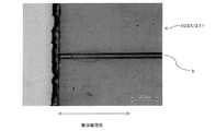
図4は、偏光子に生じるナノスリットaの発生と拡張、修復に係る片保護偏光フィルム10または透明樹脂層付の片保護偏光フィルム11の断面図の写真の一例である。図4(A)は、偏光子1の片面にのみ接着剤層2aを介して保護フィルム2を有する片保護偏光フィルム10であり、ナノスリットは発生していない場合の一例である。図4(B)は、片保護偏光フィルム10にナノスリットaが発生している場合の一例である。図4(A)、(B)はいずれも、加熱前である。また、図4(C)は、ナノスリットaが発生している片保護偏光フィルム10を加熱した後の断面図の写真の一例である。図4(C)では、加熱により偏光子1のナノスリットaが拡張していることが分かる。一方、図4(D)は、ナノスリットaが発生した片保護偏光フィルム10に、透明樹脂層3を形成した透明樹脂層付の片保護偏光フィルム11の断面図の写真の一例である。図4(D)では、偏光子1に生じたナノスリットaは透明樹脂層3により修復(a´)されていることが分かる。また、図4(E)は、透明樹脂層3形成した透明樹脂層付の片保護偏光フィルム11を加熱した後の断面図の写真の一例である。図4(E)では、加熱後に、修復(a´)されたナノスリットの拡張のないことが分かる。図4は、サンプルの吸収軸方向に対して垂直にクロスセッションポリッシャーやミクロトームにて断面切削し、走査型電子顕微鏡にて観察を行った。
FIG. 4 is an example of a photograph of a cross-sectional view of a single-protective
<偏光子>
本発明では、厚み12μm以下の偏光子を用いる。偏光子の厚みは薄型化および貫通クラックの発生を抑える観点から10μm以下であるのが好ましく、さらには8μm以下であるのが好ましく、さらには7μm以下、さらには6μm以下であるのが好ましい。一方、偏光子の厚みは2μm以上、さらには3μm以上であるのが好ましい。このような薄型の偏光子は、厚みムラが少なく、視認性が優れており、また寸法変化が少ないため熱衝撃に対する耐久性に優れる。
<Polarizer>
In the present invention, a polarizer having a thickness of 12 μm or less is used. The thickness of the polarizer is preferably 10 μm or less, more preferably 8 μm or less, further preferably 7 μm or less, and further preferably 6 μm or less from the viewpoint of thinning and suppressing the occurrence of through cracks. On the other hand, the thickness of the polarizer is preferably 2 μm or more, more preferably 3 μm or more. Such a thin polarizing element has less uneven thickness, excellent visibility, and less dimensional change, so that it has excellent durability against thermal shock.
偏光子は、ポリビニルアルコール系樹脂を用いたものが使用される。偏光子としては、例えば、ポリビニルアルコール系フィルム、部分ホルマール化ポリビニルアルコール系フィルム、エチレン・酢酸ビニル共重合体系部分ケン化フィルム等の親水性高分子フィルムに、ヨウ素や二色性染料の二色性物質を吸着させて一軸延伸したもの、ポリビニルアルコールの脱水処理物やポリ塩化ビニルの脱塩酸処理物等ポリエン系配向フィルム等が挙げられる。これらの中でも、ポリビニルアルコール系フィルムとヨウ素などの二色性物質からなる偏光子が好適である。 As the polarizer, one using a polyvinyl alcohol-based resin is used. Examples of the polarizer include a hydrophilic polymer film such as a polyvinyl alcohol-based film, a partially formalized polyvinyl alcohol-based film, and an ethylene-vinyl acetate copolymerization system partially saponified film, and a bicolor property of iodine or a bicolor dye. Examples thereof include a uniaxially stretched film by adsorbing a substance, a polyene-based oriented film such as a dehydrated product of polyvinyl alcohol and a dehydrogenated product of polyvinyl chloride. Among these, a polarizer made of a polyvinyl alcohol-based film and a dichroic substance such as iodine is preferable.
ポリビニルアルコール系フィルムをヨウ素で染色し一軸延伸した偏光子は、例えば、ポリビニルアルコールをヨウ素の水溶液に浸漬することによって染色し、元長の3〜7倍に延伸することで作製することができる。必要に応じてホウ酸や硫酸亜鉛、塩化亜鉛等を含んでいても良いし、ヨウ化カリウムなどの水溶液に浸漬することもできる。さらに必要に応じて染色前にポリビニルアルコール系フィルムを水に浸漬して水洗してもよい。ポリビニルアルコール系フィルムを水洗することでポリビニルアルコール系フィルム表面の汚れやブロッキング防止剤を洗浄することができるほかに、ポリビニルアルコール系フィルムを膨潤させることで染色のムラなどの不均一を防止する効果もある。延伸はヨウ素で染色した後に行っても良いし、染色しながら延伸しても良いし、また延伸してからヨウ素で染色しても良い。ホウ酸やヨウ化カリウムなどの水溶液や水浴中でも延伸することができる。 A polarizer obtained by dyeing a polyvinyl alcohol-based film with iodine and uniaxially stretching it can be produced, for example, by dyeing polyvinyl alcohol by immersing it in an aqueous solution of iodine and stretching it 3 to 7 times its original length. If necessary, boric acid, zinc sulfate, zinc chloride and the like may be contained, or the mixture may be immersed in an aqueous solution such as potassium iodide. Further, if necessary, the polyvinyl alcohol-based film may be immersed in water and washed with water before dyeing. In addition to being able to clean the surface of the polyvinyl alcohol film and blocking inhibitors by washing the polyvinyl alcohol film with water, it also has the effect of preventing non-uniformity such as uneven dyeing by swelling the polyvinyl alcohol film. be. Stretching may be performed after dyeing with iodine, stretching while dyeing, or stretching and then dyeing with iodine. It can be stretched even in an aqueous solution such as boric acid or potassium iodide or in a water bath.
偏光子はホウ酸を含有していることが延伸安定性や光学耐久性の点から好ましい。また、偏光子に含まれるホウ酸含有量は、貫通クラックおよびナノスリットの発生抑制、拡張抑制の観点から、偏光子全量に対して25重量%以下であるのが好ましく、さらには20重量%以下であるのが好ましく、さらには18重量%以下、さらには16重量%以下であることが好ましい。偏光子に含まれるホウ酸含有量が20重量%を超える場合には、偏光子の厚みを10μm以下に制御した場合であっても偏光子の収縮応力が高まり貫通クラックが発生しやすくなるため好ましくない。一方、偏光子の延伸安定性や光学耐久性の観点から、偏光子全量に対するホウ酸含有量は10重量%以上であることが好ましく、さらには12重量%以上であることが好ましい。 It is preferable that the polarizer contains boric acid from the viewpoint of stretch stability and optical durability. Further, the boric acid content contained in the polarizer is preferably 25% by weight or less, more preferably 20% by weight or less, based on the total amount of the polarizer from the viewpoint of suppressing the generation of through cracks and nanoslits and suppressing expansion. It is preferably 18% by weight or less, and more preferably 16% by weight or less. When the boric acid content in the polarizer exceeds 20% by weight, the shrinkage stress of the polarizer increases and through cracks are likely to occur even when the thickness of the polarizer is controlled to 10 μm or less, which is preferable. No. On the other hand, from the viewpoint of stretching stability and optical durability of the polarizer, the boric acid content with respect to the total amount of the polarizer is preferably 10% by weight or more, more preferably 12% by weight or more.
薄型の偏光子としては、代表的には、
特許第4751486号明細書、
特許第4751481号明細書、
特許第4815544号明細書、
特許第5048120号明細書、
特許第5587517号明細書、
国際公開第2014/077599号パンフレット、
国際公開第2014/077636号パンフレット、
等に記載されている薄型偏光子またはこれらに記載の製造方法から得られる薄型偏光子を挙げることができる。
As a thin polarizer, typically
Japanese Patent No. 4751486,
Japanese Patent No. 4751481
Patent No. 4815544,
Japanese Patent No. 5048120,
Japanese Patent No. 5587517,
International Publication No. 2014/07759 Pamphlet,
International Publication No. 2014/077636 Pamphlet,
Etc., or the thin polarizing element obtained from the manufacturing method described in these.
前記偏光子は、単体透過率T及び偏光度Pによって表される光学特性が、次式
P>−(100.929T−42.4−1)×100(ただし、T<42.3)、又は、
P≧99.9(ただし、T≧42.3)の条件を満足するように構成されている。前記条件を満足するように構成された偏光子は、一義的には、大型表示素子を用いた液晶テレビ用のディスプレイとして求められる性能を有する。具体的にはコントラスト比1000:1以上かつ最大輝度500cd/m2以上である。他の用途としては、例えば有機EL表示装置の視認側に貼り合される。
The polarizer has optical characteristics represented by a simple substance transmittance T and a degree of polarization P of the following equation P> − (10 0.929 T-42.4 -1) × 100 (where T <42.3). Or,
It is configured to satisfy the condition of P ≧ 99.9 (however, T ≧ 42.3). A polarizer configured to satisfy the above conditions primarily has the performance required for a display for a liquid crystal television using a large display element. Specifically, the contrast ratio is 1000: 1 or more and the maximum brightness is 500 cd / m 2 or more. As another application, for example, it is bonded to the visual side of an organic EL display device.
一方、前記条件を満足するように構成された偏光子は、構成する高分子(例えばポリビニルアルコール系分子)が高い配向性を示すため、厚み10μm以下であることと相俟って、偏光子の吸収軸方向に直交する方向の引張破断応力が顕著に小さくなる。その結果、例えば、偏光フィルムの製造過程において当該引張破断応力を超える機械的衝撃に晒された際に、ナノスリットが偏光子の吸収軸方向に生じる可能性が極めて高い。よって、本発明は、当該偏光子を採用した片保護偏光フィルム(またはそれを用いた粘着剤層付偏光フィルム)に特に好適である。 On the other hand, a polarizer configured to satisfy the above conditions has a thickness of 10 μm or less because the constituent polymer (for example, a polyvinyl alcohol-based molecule) exhibits high orientation. The tensile breaking stress in the direction orthogonal to the absorption axis direction is significantly reduced. As a result, for example, when exposed to a mechanical impact exceeding the tensile breaking stress in the manufacturing process of the polarizing film, there is an extremely high possibility that nanoslits are generated in the absorption axis direction of the polarizer. Therefore, the present invention is particularly suitable for a single-protective polarizing film (or a polarizing film with an adhesive layer using the same) that employs the polarizer.
前記薄型偏光子としては、積層体の状態で延伸する工程と染色する工程を含む製法の中でも、高倍率に延伸できて偏光性能を向上させることのできる点で、特許第4751486号明細書、特許第4751481号明細書、特許4815544号明細書に記載のあるようなホウ酸水溶液中で延伸する工程を含む製法で得られるものが好ましく、特に特許第4751481号明細書、特許4815544号明細書に記載のあるホウ酸水溶液中で延伸する前に補助的に空中延伸する工程を含む製法により得られるものが好ましい。これら薄型偏光子は、ポリビニルアルコール系樹脂(以下、PVA系樹脂ともいう)層と延伸用樹脂基材を積層体の状態で延伸する工程と染色する工程を含む製法によって得ることができる。この製法であれば、PVA系樹脂層が薄くても、延伸用樹脂基材に支持されていることにより延伸による破断などの不具合なく延伸することが可能となる。 The thin polarizer is patented in Patent No. 4751486, in that it can be stretched at a high magnification and the polarization performance can be improved even in a manufacturing method including a step of stretching in a laminated state and a step of dyeing. Those obtained by a production method including a step of stretching in an aqueous boric acid solution as described in Japanese Patent No. 4751481 and Japanese Patent No. 4815544 are preferable, and particularly described in Japanese Patent No. 4751481 and Japanese Patent No. 4815544. It is preferably obtained by a production method including a step of auxiliary stretching in the air before stretching in a certain boric acid aqueous solution. These thin polarizers can be obtained by a production method including a step of stretching a polyvinyl alcohol-based resin (hereinafter, also referred to as PVA-based resin) layer and a resin base material for stretching in a laminated state and a step of dyeing. With this manufacturing method, even if the PVA-based resin layer is thin, it can be stretched without problems such as breakage due to stretching because it is supported by the stretching resin base material.
<保護フィルム>
前記保護フィルムを構成する材料としては、透明性、機械的強度、熱安定性、水分遮断性、等方性などに優れるものが好ましい。例えば、ポリエチレンテレフタレートやポリエチレンナフタレートなどのポリエステル系ポリマー、ジアセチルセルロースやトリアセチルセルロースなどのセルロース系ポリマー、ポリメチルメタクリレートなどのアクリル系ポリマー、ポリスチレンやアクリロニトリル・スチレン共重合体(AS樹脂)などのスチレン系ポリマー、ポリカーボネート系ポリマー等が挙げられる。また、ポリエチレン、ポリプロピレン、シクロ系ないしはノルボルネン構造を有するポリオレフィン、エチレン・プロピレン共重合体の如きポリオレフィン系ポリマー、塩化ビニル系ポリマー、ナイロンや芳香族ポリアミドなどのアミド系ポリマー、イミド系ポリマー、スルホン系ポリマー、ポリエーテルスルホン系ポリマー、ポリエーテルエーテルケトン系ポリマー、ポリフェニレンスルフィド系ポリマー、ビニルアルコール系ポリマー、塩化ビニリデン系ポリマー、ビニルブチラール系ポリマー、アリレート系ポリマー、ポリオキシメチレン系ポリマー、エポキシ系ポリマー、または上記ポリマーのブレンド物なども上記保護フィルムを形成するポリマーの例として挙げられる。
<Protective film>
As the material constituting the protective film, those having excellent transparency, mechanical strength, thermal stability, moisture blocking property, isotropic property and the like are preferable. For example, polyester polymers such as polyethylene terephthalate and polyethylene naphthalate, cellulose polymers such as diacetyl cellulose and triacetyl cellulose, acrylic polymers such as polymethyl methacrylate, and styrene such as polystyrene and acrylonitrile-styrene copolymer (AS resin). Examples thereof include based polymers and polystyrene polymers. In addition, polyethylene, polypropylene, polyolefins having a cyclo- or norbornene structure, polyolefin-based polymers such as ethylene / propylene copolymers, vinyl chloride-based polymers, amide-based polymers such as nylon and aromatic polyamide, imide-based polymers, and sulfone-based polymers. , Polyether sulfone polymer, polyether ether ketone polymer, polyphenylene sulfide polymer, vinyl alcohol polymer, vinylidene chloride polymer, vinyl butyral polymer, allylate polymer, polyoxymethylene polymer, epoxy polymer, or the above. Polymer blends and the like are also examples of polymers that form the protective film.
なお、保護フィルム中には任意の適切な添加剤が1種類以上含まれていてもよい。添加剤としては、例えば、紫外線吸収剤、酸化防止剤、滑剤、可塑剤、離型剤、着色防止剤、難燃剤、核剤、帯電防止剤、顔料、着色剤などがあげられる。保護フィルム中の上記熱可塑性樹脂の含有量は、好ましくは50〜100重量%、より好ましくは50〜99重量%、さらに好ましくは60〜98重量%、特に好ましくは70〜97重量%である。保護フィルム中の上記熱可塑性樹脂の含有量が50重量%以下の場合、熱可塑性樹脂が本来有する高透明性等が十分に発現できないおそれがある。 In addition, one or more kinds of arbitrary suitable additives may be contained in a protective film. Examples of the additive include an ultraviolet absorber, an antioxidant, a lubricant, a plasticizer, a mold release agent, a color retardant, a flame retardant, a nucleating agent, an antistatic agent, a pigment, a colorant and the like. The content of the thermoplastic resin in the protective film is preferably 50 to 100% by weight, more preferably 50 to 99% by weight, still more preferably 60 to 98% by weight, and particularly preferably 70 to 97% by weight. When the content of the thermoplastic resin in the protective film is 50% by weight or less, the high transparency inherent in the thermoplastic resin may not be sufficiently exhibited.
前記保護フィルムとしては、位相差フィルム、輝度向上フィルム、拡散フィルム等も用いることができる。位相差フィルムとしては、正面位相差が40nm以上および/または、厚み方向位相差が80nm以上の位相差を有するものが挙げられる。正面位相差は、通常、40〜200nmの範囲に、厚み方向位相差は、通常、80〜300nmの範囲に制御される。保護フィルムとして位相差フィルムを用いる場合には、当該位相差フィルムが偏光子保護フィルムとしても機能するため、薄型化を図ることができる。 As the protective film, a retardation film, a brightness improving film, a diffusion film and the like can also be used. Examples of the retardation film include those having a frontal retardation of 40 nm or more and / or a thickness direction retardation of 80 nm or more. The front phase difference is usually controlled in the range of 40 to 200 nm, and the thickness direction phase difference is usually controlled in the range of 80 to 300 nm. When a retardation film is used as the protective film, the retardation film also functions as a polarizer protective film, so that the thickness can be reduced.
位相差フィルムとしては、熱可塑性樹脂フィルムを一軸または二軸延伸処理してなる複屈折性フィルムが挙げられる。上記延伸の温度、延伸倍率等は、位相差値、フィルムの材料、厚みにより適宜に設定される。 Examples of the retardation film include a birefringent film obtained by uniaxially or biaxially stretching a thermoplastic resin film. The stretching temperature, stretching ratio, and the like are appropriately set depending on the retardation value, the film material, and the thickness.
保護フィルムの厚さは、適宜に決定しうるが、一般には強度や取扱性等の作業性、薄層性などの点より1〜500μm程度である。特に1〜300μmが好ましく、5〜200μmがより好ましい。特に、保護フィルムが1枚の場合には、薄型化の観点から厚みは100μm以下が好ましく、さらには80μm以下、さらには60μm以下であることが好ましい。また、偏光フィルムを折れや破断から保護する観点から10μm以上が好ましく、さらには20μm以上が好ましい。また、保護フィルムの厚みをV(μm)とした場合には、偏光子の厚みX(μm)、透明樹脂層の厚さY(μm)との関係において、偏光フィルムに機械的応力が加わった際に偏光子が折れるのを抑制する観点から、4X≦(Y+V)を満足することが好ましく、さらには、5X≦(Y+V)、を満足することが好ましい。 The thickness of the protective film can be appropriately determined, but is generally about 1 to 500 μm in terms of workability such as strength and handleability, and thin layer property. In particular, 1 to 300 μm is preferable, and 5 to 200 μm is more preferable. In particular, when one protective film is used, the thickness is preferably 100 μm or less, more preferably 80 μm or less, and further preferably 60 μm or less from the viewpoint of thinning. Further, from the viewpoint of protecting the polarizing film from breakage or breakage, it is preferably 10 μm or more, and more preferably 20 μm or more. Further, when the thickness of the protective film is V (μm), mechanical stress is applied to the polarizing film in relation to the thickness X (μm) of the polarizer and the thickness Y (μm) of the transparent resin layer. From the viewpoint of suppressing the polarizer from breaking, it is preferable to satisfy 4X ≦ (Y + V), and further preferably 5X ≦ (Y + V).
また、前記保護フィルムは2枚用いることができる。2枚の保護フィルムは、偏光フィルムを折れや破断から保護する観点から、各保護フィルムの合計厚みが10μm以上、さらには20μm以上であるのが好ましく、かつ片保護偏光フィルムの薄型化の観点から各保護フィルムの合計厚みが100μm以下になるように制御するのが好ましい。 Further, two protective films can be used. From the viewpoint of protecting the polarizing films from breakage and breakage, the total thickness of the two protective films is preferably 10 μm or more, more preferably 20 μm or more, and from the viewpoint of reducing the thickness of the single protective polarizing film. It is preferable to control the total thickness of each protective film to be 100 μm or less.
前記保護フィルムの偏光子を接着させない面(特に、図1の態様)には、ハードコート層、反射防止層、スティッキング防止層、拡散層ないしアンチグレア層などの機能層を設けることができる。なお、上記ハードコート層、反射防止層、スティッキング防止層、拡散層やアンチグレア層などの機能層は、保護フィルムそのものに設けることができるほか、別途、保護フィルムとは別体のものとして設けることもできる。 A functional layer such as a hard coat layer, an antireflection layer, an anti-sticking layer, a diffusion layer or an anti-glare layer can be provided on the surface of the protective film from which the polarizer is not adhered (particularly, the aspect of FIG. 1). The functional layers such as the hard coat layer, the antireflection layer, the sticking prevention layer, the diffusion layer and the antiglare layer can be provided on the protective film itself, or may be provided separately from the protective film. can.
<介在層>
前記保護フィルムと偏光子は接着剤層、粘着剤層、下塗り層(プライマー層)などの介在層を介して積層される。この際、介在層により両者を空気間隙なく積層することが望ましい。前記保護フィルムと偏光子は接着剤層を介して積層するのが好ましい。
<Intervening layer>
The protective film and the polarizer are laminated via an intervening layer such as an adhesive layer, an adhesive layer, and an undercoat layer (primer layer). At this time, it is desirable that both are laminated without an air gap by an intervening layer. The protective film and the polarizer are preferably laminated via an adhesive layer.
接着剤層は接着剤により形成される。接着剤の種類は特に制限されず、種々のものを用いることができる。前記接着剤層は光学的に透明であれば特に制限されず、接着剤としては、水系、溶剤系、ホットメルト系、活性エネルギー線硬化型等の各種形態のものが用いられるが、水系接着剤または活性エネルギー線硬化型接着剤が好適である。 The adhesive layer is formed by the adhesive. The type of adhesive is not particularly limited, and various adhesives can be used. The adhesive layer is not particularly limited as long as it is optically transparent, and various forms such as water-based, solvent-based, hot-melt-based, and active energy ray-curable type are used as the adhesive. Alternatively, an active energy ray-curable adhesive is suitable.
水系接着剤としては、イソシアネート系接着剤、ポリビニルアルコール系接着剤、ゼラチン系接着剤、ビニル系ラテックス系、水系ポリエステル等を例示できる。水系接着剤は、通常、水溶液からなる接着剤として用いられ、通常、0.5〜60重量%の固形分を含有してなる。なかでも、イソシアネート系接着剤、ポリビニルアルコール系接着剤が好ましい。イソシアネート系接着剤からは接着剤層としてウレタン系樹脂層が形成される。 Examples of the water-based adhesive include isocyanate-based adhesives, polyvinyl alcohol-based adhesives, gelatin-based adhesives, vinyl-based latex-based adhesives, and water-based polyesters. The water-based adhesive is usually used as an adhesive composed of an aqueous solution, and usually contains 0.5 to 60% by weight of a solid content. Of these, isocyanate-based adhesives and polyvinyl alcohol-based adhesives are preferable. A urethane-based resin layer is formed as an adhesive layer from the isocyanate-based adhesive.
活性エネルギー線硬化型接着剤は、電子線、紫外線(ラジカル硬化型、カチオン硬化型)等の活性エネルギー線により硬化が進行する接着剤であり、例えば、電子線硬化型、紫外線硬化型の態様で用いることができる。活性エネルギー線硬化型接着剤は、例えば、光ラジカル硬化型接着剤を用いることができる。光ラジカル硬化型の活性エネルギー線硬化型接着剤を、紫外線硬化型として用いる場合には、当該接着剤は、ラジカル重合性化合物および光重合開始剤を含有する。例えば、ラジカル硬化型の紫外線硬化型接着剤としては紫外線硬化型アクリル系樹脂が好ましく、カチオン硬化型の紫外線硬化型接着剤としては紫外線硬化型エポキシ系樹脂が好ましい。 The active energy ray-curable adhesive is an adhesive whose curing proceeds by active energy rays such as electron beam and ultraviolet rays (radical curing type, cationic curing type). For example, in the form of electron beam curing type and ultraviolet curing type. Can be used. As the active energy ray-curable adhesive, for example, a photoradical curable adhesive can be used. When a photoradical-curable active energy ray-curable adhesive is used as an ultraviolet curable type, the adhesive contains a radical-polymerizable compound and a photopolymerization initiator. For example, the radical-curable UV-curable adhesive is preferably a UV-curable acrylic resin, and the cationically curable UV-curable adhesive is preferably a UV-curable epoxy resin.
接着剤の塗工方式は、接着剤の粘度や目的とする厚みによって適宜に選択される。塗工方式の例として、例えば、リバースコーター、グラビアコーター(ダイレクト,リバースやオフセット)、バーリバースコーター、ロールコーター、ダイコーター、バーコーター、ロッドコーター等が挙げられる。その他、塗工には、デイッピング方式などの方式を適宜に使用することができる。 The adhesive coating method is appropriately selected depending on the viscosity of the adhesive and the desired thickness. Examples of the coating method include a reverse coater, a gravure coater (direct, reverse and offset), a bar reverse coater, a roll coater, a die coater, a bar coater, a rod coater and the like. In addition, a method such as a dipping method can be appropriately used for coating.
また、前記接着剤層の厚みは、0.1μm以上5μm以下であることが好ましく、水系接着剤または活性エネルギー線硬化型接着剤の種類により好ましい範囲を設定できる。前記厚みを0.1μm以上とすることは接着力を維持する点から好ましく、5μm以下とすることは光学信頼性を確保する点から好ましい。前記接着剤の塗工は、水系接着剤等を用いる場合には、最終的に形成される接着剤層の厚みが100〜300nmになるように行うのが好ましい。前記接着剤層の厚さは、さらに好ましくは100〜250nmである。一方、活性エネルギー線硬化型接着剤を用いる場合には、前記接着剤層の厚みは、0.2〜5μmになるよう行うのが好ましい。より好ましくは、0.2〜2μm、さらに好ましくは0.5〜1.5μmである。 The thickness of the adhesive layer is preferably 0.1 μm or more and 5 μm or less, and a preferable range can be set depending on the type of the water-based adhesive or the active energy ray-curable adhesive. The thickness of 0.1 μm or more is preferable from the viewpoint of maintaining the adhesive force, and the thickness of 5 μm or less is preferable from the viewpoint of ensuring optical reliability. When a water-based adhesive or the like is used, the adhesive is preferably applied so that the thickness of the finally formed adhesive layer is 100 to 300 nm. The thickness of the adhesive layer is more preferably 100 to 250 nm. On the other hand, when an active energy ray-curable adhesive is used, the thickness of the adhesive layer is preferably 0.2 to 5 μm. It is more preferably 0.2 to 2 μm, still more preferably 0.5 to 1.5 μm.
また、前記接着剤層は、偏光子にかかる力を緩和しつつ貫通クラックを抑制するうえで、80℃における圧縮弾性率が0.1GPa以上10GPa以下であることが好ましい。前記圧縮弾性率を0.1GPa以上とすることは、衝撃吸収をして耐クラック性(ナノスリットの発生抑制および貫通クラックの抑制)を確保するうえで好ましく、10GPa以下とすることは偏光子収縮を抑制できず貫通クラックを抑制する点から好ましい。特に、前記接着剤層を活性エネルギー線硬化型接着剤により形成されている場合には、前記圧縮弾性率は、1GPa以上が好ましく、さらには3GPa以上が好ましい。一方、前記圧縮弾性率は8GPa以下が好ましい。 Further, the adhesive layer preferably has a compressive elastic modulus at 80 ° C. of 0.1 GPa or more and 10 GPa or less in order to suppress through cracks while relaxing the force applied to the polarizer. It is preferable that the compressive elastic modulus is 0.1 GPa or more in order to absorb impact and secure crack resistance (suppression of occurrence of nanoslits and suppression of through cracks), and it is preferable that the compressive elastic modulus is 10 GPa or less. It is preferable from the viewpoint that it cannot suppress the penetration crack and suppresses the through crack. In particular, when the adhesive layer is formed of an active energy ray-curable adhesive, the compressive elastic modulus is preferably 1 GPa or more, more preferably 3 GPa or more. On the other hand, the compressive elastic modulus is preferably 8 GPa or less.
なお、偏光子と保護フィルムの積層にあたって、保護フィルムと接着剤層の間には、易接着層を設けることができる。易接着層は、例えば、ポリエステル骨格、ポリエーテル骨格、ポリカーボネート骨格、ポリウレタン骨格、シリコーン系、ポリアミド骨格、ポリイミド骨格、ポリビニルアルコール骨格などを有する各種樹脂により形成することができる。これらポリマー樹脂は1種を単独で、または2種以上を組み合わせて用いることができる。また易接着層の形成には他の添加剤を加えてもよい。具体的にはさらには粘着付与剤、紫外線吸収剤、酸化防止剤、耐熱安定剤などの安定剤などを用いてもよい。 When laminating the polarizer and the protective film, an easy-adhesion layer can be provided between the protective film and the adhesive layer. The easy-adhesion layer can be formed of, for example, various resins having a polyester skeleton, a polyether skeleton, a polycarbonate skeleton, a polyurethane skeleton, a silicone-based material, a polyamide skeleton, a polyimide skeleton, a polyvinyl alcohol skeleton, and the like. These polymer resins may be used alone or in combination of two or more. Further, other additives may be added to form the easy-adhesion layer. Specifically, a tackifier, an ultraviolet absorber, an antioxidant, a stabilizer such as a heat-resistant stabilizer, or the like may be used.
易接着層は、通常、保護フィルムに予め設けておき、当該保護フィルムの易接着層側と偏光子とを接着剤層により積層する。易接着層の形成は、易接着層の形成材を保護フィルム上に、公知の技術により塗工、乾燥することにより行われる。易接着層の形成材は、乾燥後の厚み、塗工の円滑性などを考慮して適当な濃度に希釈した溶液として、通常調整される。易接着層は乾燥後の厚みは、好ましくは0.01〜5μm、さらに好ましくは0.02〜2μm、さらに好ましくは0.05〜1μmである。なお、易接着層は複数層設けることができるが、この場合にも、易接着層の総厚みは上記範囲になるようにするのが好ましい。 The easy-adhesive layer is usually provided in advance on the protective film, and the easy-adhesive layer side of the protective film and the polarizer are laminated by the adhesive layer. The easy-adhesive layer is formed by applying a material for forming the easy-adhesive layer onto a protective film by a known technique and drying it. The material for forming the easy-adhesion layer is usually adjusted as a solution diluted to an appropriate concentration in consideration of the thickness after drying, the smoothness of coating, and the like. The thickness of the easy-adhesion layer after drying is preferably 0.01 to 5 μm, more preferably 0.02 to 2 μm, and further preferably 0.05 to 1 μm. A plurality of easy-adhesive layers can be provided, but even in this case, it is preferable that the total thickness of the easy-adhesive layers is within the above range.
粘着剤層は、粘着剤から形成される。粘着剤としては各種の粘着剤を用いることができ、例えば、ゴム系粘着剤、アクリル系粘着剤、シリコーン系粘着剤、ウレタン系粘着剤、ビニルアルキルエーテル系粘着剤、ポリビニルピロリドン系粘着剤、ポリアクリルアミド系粘着剤、セルロース系粘着剤などが挙げられる。前記粘着剤の種類に応じて粘着性のベースポリマーが選択される。前記粘着剤のなかでも、光学的透明性に優れ、適宜な濡れ性と凝集性と接着性の粘着特性を示して、耐候性や耐熱性などに優れる点から、アクリル系粘着剤が好ましく使用される。 The pressure-sensitive adhesive layer is formed from the pressure-sensitive adhesive. Various adhesives can be used as the adhesive, for example, rubber adhesive, acrylic adhesive, silicone adhesive, urethane adhesive, vinyl alkyl ether adhesive, polyvinylpyrrolidone adhesive, poly. Examples include acrylamide-based adhesives and cellulose-based adhesives. A sticky base polymer is selected according to the type of the pressure-sensitive adhesive. Among the above-mentioned adhesives, acrylic adhesives are preferably used because they are excellent in optical transparency, exhibit appropriate wettability, cohesiveness and adhesive properties, and are excellent in weather resistance and heat resistance. NS.
下塗り層(プライマー層)は、偏光子と保護フィルムとの密着性を向上させるために形成される。プライマー層を構成する材料としては、基材フィルムとポリビニルアルコール系樹脂層との両方にある程度強い密着力を発揮する材料であれば特に限定されない。たとえば、透明性、熱安定性、延伸性などに優れる熱可塑性樹脂などが用いられる。熱可塑性樹脂としては、例えば、アクリル系樹脂、ポリオレフィン系樹脂、ポリエステル系樹脂、ポリビニルアルコール系樹脂、又はそれらの混合物が挙げられる。 The undercoat layer (primer layer) is formed to improve the adhesion between the polarizer and the protective film. The material constituting the primer layer is not particularly limited as long as it is a material that exhibits a certain degree of strong adhesion to both the base film and the polyvinyl alcohol-based resin layer. For example, a thermoplastic resin having excellent transparency, thermal stability, stretchability, etc. is used. Examples of the thermoplastic resin include acrylic resins, polyolefin resins, polyester resins, polyvinyl alcohol resins, and mixtures thereof.
また、前記保護フィルムを少なくとも2枚を用いる場合の各保護フィルムの積層は接着剤層または粘着剤層を介することが好ましい。前記接着剤層の厚さは接着力の観点から0.1μm以上、さらには0.2μm以上であるのが好ましい。一方、薄型化の観点から前記接着剤層の厚さは5μm以下が好ましく、さらには2μm以下が好ましい。また、各保護フィルムの積層に粘着剤を用いる場合には、厚さは粘着力の観点から2μm以上であることが好ましい。一方、薄型化の観点から前記粘着剤層の厚さは20μm以下であることが好ましい。 Further, when at least two protective films are used, it is preferable that the protective films are laminated via an adhesive layer or an adhesive layer. The thickness of the adhesive layer is preferably 0.1 μm or more, more preferably 0.2 μm or more from the viewpoint of adhesive strength. On the other hand, from the viewpoint of thinning, the thickness of the adhesive layer is preferably 5 μm or less, more preferably 2 μm or less. When an adhesive is used for laminating each protective film, the thickness is preferably 2 μm or more from the viewpoint of adhesive strength. On the other hand, from the viewpoint of thinning, the thickness of the pressure-sensitive adhesive layer is preferably 20 μm or less.
<透明樹脂層>
透明樹脂層は、偏光子の片面にのみ保護フィルムが設けられた片保護偏光フィルムにおいて、偏光子の他の片面(保護フィルムを積層していない面)に設けられる。本発明において、透明樹脂層は、80℃における圧縮弾性率0.1GPa以上であることが好ましい。仮に、機械衝撃により偏光子にナノスリットが生じ、熱環境下においてナノスリットが幅方向へ広がろうとしても、透明樹脂層の80℃における圧縮弾性率を0.1GPa以上に制御することで、熱環境下においても透明樹脂層の機械的保持能力を維持して、ナノスリットが幅方向へ広がるのを抑えることができる。透明樹脂層の圧縮弾性率は0.5GPa以上、さらには2GPa以上、さらには3GPa以上、さらには5GPa以上、さらには6GPa以上、さらには10GPa以上であるのが好ましい。透明樹脂層の圧縮弾性率は、材料選定により調整することができる。なお、透明樹脂層の80℃における圧縮弾性率は実施例の記載に基づいて測定される値である。
<Transparent resin layer>
The transparent resin layer is provided on the other side of the polarizer (the surface on which the protective film is not laminated) in the one-sided protective polarizing film in which the protective film is provided on only one side of the polarizer. In the present invention, the transparent resin layer preferably has a compressive elastic modulus of 0.1 GPa or more at 80 ° C. Even if nanoslits are generated in the polarizer due to mechanical impact and the nanoslits try to widen in the width direction in a thermal environment, the compressive elastic modulus of the transparent resin layer at 80 ° C. is controlled to 0.1 GPa or more. Even in a thermal environment, the mechanical holding capacity of the transparent resin layer can be maintained, and the nanoslits can be suppressed from expanding in the width direction. The compressive elastic modulus of the transparent resin layer is preferably 0.5 GPa or more, more preferably 2 GPa or more, further 3 GPa or more, further 5 GPa or more, further 6 GPa or more, and further preferably 10 GPa or more. The compressive elastic modulus of the transparent resin layer can be adjusted by selecting the material. The compressive elastic modulus of the transparent resin layer at 80 ° C. is a value measured based on the description of Examples.
透明樹脂層の厚さは、薄層化および光学信頼性の観点から、透明樹脂層の厚さ(Y)は、15μm以下である。また、透明樹脂層が厚くなると保存した後に片保護偏光フィルムにカールが発生しやすくなる。透明樹脂層の厚さ(Y)は、さらには12μm以下であるのが好ましく、さらには5μm以下、さらには1.5μm以下であるのが好ましい。一方、透明樹脂層の厚さ(Y)は、ナノスリットの拡張抑制効果の観点から、0.2μm以上であるのが好ましく、さらには0.5μm以上が好ましく、さらには0.6μm以上が好ましく、さらには0.8μm以上であるのが好ましい。透明樹脂層の厚さ(Y)は、偏光子の厚さX(μm)との関係において、0.15≦(Y/X)≦3、を満足するように制御される。 The thickness of the transparent resin layer (Y) is 15 μm or less from the viewpoint of thinning and optical reliability. Further, when the transparent resin layer becomes thick, the one-sided protective polarizing film tends to be curled after being stored. The thickness (Y) of the transparent resin layer is preferably 12 μm or less, more preferably 5 μm or less, and further preferably 1.5 μm or less. On the other hand, the thickness (Y) of the transparent resin layer is preferably 0.2 μm or more, more preferably 0.5 μm or more, and further preferably 0.6 μm or more from the viewpoint of the expansion suppressing effect of the nanoslit. Further, it is preferably 0.8 μm or more. The thickness (Y) of the transparent resin layer is controlled so as to satisfy 0.15 ≦ (Y / X) ≦ 3 in relation to the thickness X (μm) of the polarizer.
透明樹脂層は、硬化性成分を含有する硬化型形成材から形成することができる。硬化性成分としては、電子線硬化型、紫外線硬化型、可視光線硬化型等の活性エネルギー線硬化型と熱硬化型に大別することができる。さらには、紫外線硬化型、可視光線硬化型は、ラジカル重合硬化型とカチオン重合硬化型に区分出来る。本発明において、波長範囲10nm〜380nm未満の活性エネルギー線を紫外線、波長範囲380nm〜800nmの活性エネルギー線を可視光線として表記する。前記ラジカル重合硬化型の硬化性成分は、熱硬化型の硬化性成分として用いることができる。 The transparent resin layer can be formed from a curable forming material containing a curable component. The curable component can be roughly classified into an active energy ray-curable type such as an electron beam-curable type, an ultraviolet-curable type, and a visible light-curable type, and a thermosetting type. Furthermore, the ultraviolet curable type and the visible light curable type can be classified into a radical polymerization curable type and a cationic polymerization curable type. In the present invention, active energy rays having a wavelength range of 10 nm to less than 380 nm are referred to as ultraviolet rays, and active energy rays having a wavelength range of 380 nm to 800 nm are referred to as visible light. The radical polymerization curable component can be used as a thermosetting curable component.
≪ラジカル重合硬化型形成材≫
前記硬化性成分としては、例えば、ラジカル重合性化合物が挙げられる。ラジカル重合性化合物は、(メタ)アクリロイル基、ビニル基等の炭素−炭素二重結合のラジカル重合性の官能基を有する化合物が挙げられる。これら硬化性成分は、単官能ラジカル重合性化合物または二官能以上の多官能ラジカル重合性化合物のいずれも用いることができる。また、これらラジカル重合性化合物は、1種を単独で、または2種以上を組み合わせて用いることができる。これらラジカル重合性化合物としては、例えば、(メタ)アクリロイル基を有する化合物が好適である。なお、本発明において、(メタ)アクリロイルとは、アクリロイル基および/またはメタクリロイル基を意味し、「(メタ)」は以下同様の意味である。
≪Radical polymerization curing type forming material≫
Examples of the curable component include radically polymerizable compounds. Examples of the radically polymerizable compound include compounds having a radically polymerizable functional group of a carbon-carbon double bond such as a (meth) acryloyl group and a vinyl group. As these curable components, either a monofunctional radical-polymerizable compound or a bifunctional or higher-functional polyfunctional radical-polymerizable compound can be used. In addition, these radically polymerizable compounds may be used alone or in combination of two or more. As these radically polymerizable compounds, for example, compounds having a (meth) acryloyl group are suitable. In addition, in this invention, (meth) acryloyl means acryloyl group and / or methacryloyl group, and "(meth)" has the same meaning below.
≪単官能ラジカル重合性化合物≫
単官能ラジカル重合性化合物としては、例えば、(メタ)アクリルアミド基を有する(メタ)アクリルアミド誘導体が挙げられる。(メタ)アクリルアミド誘導体は、偏光子との密着性を確保するうえで、また、重合速度が速く生産性に優れる点で好ましい。(メタ)アクリルアミド誘導体の具体例としては、例えば、N−メチル(メタ)アクリルアミド、N,N−ジメチル(メタ)アクリルアミド、N,N−ジエチル(メタ)アクリルアミド、N−イソプロピル(メタ)アクリルアミド、N−ブチル(メタ)アクリルアミド、N−ヘキシル(メタ)アクリルアミド等のN−アルキル基含有(メタ)アクリルアミド誘導体;N−メチロール(メタ)アクリルアミド、N−ヒドロキシエチル(メタ)アクリルアミド、N−メチロール−N−プロパン(メタ)アクリルアミド等のN−ヒドロキシアルキル基含有(メタ)アクリルアミド誘導体;アミノメチル(メタ)アクリルアミド、アミノエチル(メタ)アクリルアミド等のN−アミノアルキル基含有(メタ)アクリルアミド誘導体;N−メトキシメチルアクリルアミド、N−エトキシメチルアクリルアミド等のN−アルコキシ基含有(メタ)アクリルアミド誘導体;メルカプトメチル(メタ)アクリルアミド、メルカプトエチル(メタ)アクリルアミド等のN−メルカプトアルキル基含有(メタ)アクリルアミド誘導体;などが挙げられる。また、(メタ)アクリルアミド基の窒素原子が複素環を形成している複素環含有(メタ)アクリルアミド誘導体としては、例えば、N−アクリロイルモルホリン、N−アクリロイルピペリジン、N−メタクリロイルピペリジン、N−アクリロイルピロリジン等があげられる。
≪Monofunctional radical polymerizable compound≫
Examples of the monofunctional radically polymerizable compound include a (meth) acrylamide derivative having a (meth) acrylamide group. The (meth) acrylamide derivative is preferable in terms of ensuring adhesion to the polarizer and in terms of high polymerization rate and excellent productivity. Specific examples of the (meth) acrylamide derivative include N-methyl (meth) acrylamide, N, N-dimethyl (meth) acrylamide, N, N-diethyl (meth) acrylamide, N-isopropyl (meth) acrylamide, and N. N-alkyl group-containing (meth) acrylamide derivatives such as −butyl (meth) acrylamide, N-hexyl (meth) acrylamide; N-methylol (meth) acrylamide, N-hydroxyethyl (meth) acrylamide, N-methylol-N- N-Hydroxyalkyl group-containing (meth) acrylamide derivatives such as propane (meth) acrylamide; N-aminoalkyl group-containing (meth) acrylamide derivatives such as aminomethyl (meth) acrylamide and aminoethyl (meth) acrylamide; N-methoxymethyl N-alkoxy group-containing (meth) acrylamide derivatives such as acrylamide and N-ethoxymethylacrylamide; N-mercaptoalkyl group-containing (meth) acrylamide derivatives such as mercaptomethyl (meth) acrylamide and mercaptoethyl (meth) acrylamide; Be done. Examples of the heterocyclic (meth) acrylamide derivative in which the nitrogen atom of the (meth) acrylamide group forms a heterocycle include N-acrylloylmorpholine, N-acrylloylpiperidin, N-methacryloylpiperidin, and N-acrylloylpyridine. And so on.
前記(メタ)アクリルアミド誘導体のなかでも、偏光子との密着性の点から、N−ヒドロキシアルキル基含有(メタ)アクリルアミド誘導体が好ましく、特に、N−ヒドロキシエチル(メタ)アクリルアミドが好ましい。 Among the (meth) acrylamide derivatives, an N-hydroxyalkyl group-containing (meth) acrylamide derivative is preferable, and N-hydroxyethyl (meth) acrylamide is particularly preferable, from the viewpoint of adhesion to a polarizer.
また、単官能ラジカル重合性化合物としては、例えば、(メタ)アクリロイルオキシ基を有する各種の(メタ)アクリル酸誘導体が挙げられる。具体的には、例えば、メチル(メタ)アクリレート、エチル(メタ)アクリレート、n−プロピル(メタ)アクリレート、イソプロピル(メタ)アクリレート、2−メチル−2−ニトロプロピル(メタ)アクリレート、n−ブチル(メタ)アクリレート、イソブチル(メタ)アクリレート、s−ブチル(メタ)アクリレート、t−ブチル(メタ)アクリレート、n−ペンチル(メタ)アクリレート、t−ペンチル(メタ)アクリレート、3−ペンチル(メタ)アクリレート、2,2−ジメチルブチル(メタ)アクリレート、n−ヘキシル(メタ)アクリレート、セチル(メタ)アクリレート、n−オクチル(メタ)アクリレート、2−エチルヘキシル(メタ)アクリレート、4−メチル−2−プロピルペンチル(メタ)アクリレート、n−オクタデシル(メタ)アクリレートなどの(メタ)アクリル酸(炭素数1−20)アルキルエステル類が挙げられる。 In addition, examples of the monofunctional radically polymerizable compound include various (meth) acrylic acid derivatives having a (meth) acryloyloxy group. Specifically, for example, methyl (meth) acrylate, ethyl (meth) acrylate, n-propyl (meth) acrylate, isopropyl (meth) acrylate, 2-methyl-2-nitropropyl (meth) acrylate, n-butyl ( Meta) acrylate, isobutyl (meth) acrylate, s-butyl (meth) acrylate, t-butyl (meth) acrylate, n-pentyl (meth) acrylate, t-pentyl (meth) acrylate, 3-pentyl (meth) acrylate, 2,2-Dimethylbutyl (meth) acrylate, n-hexyl (meth) acrylate, cetyl (meth) acrylate, n-octyl (meth) acrylate, 2-ethylhexyl (meth) acrylate, 4-methyl-2-propylpentyl ( Examples thereof include (meth) acrylic acid (1-20 carbon atoms) alkyl esters such as meta) acrylate and n-octadecyl (meth) acrylate.
また、前記(メタ)アクリル酸誘導体としては、例えば、シクロヘキシル(メタ)アクリレート、シクロペンチル(メタ)アクリレート等のシクロアルキル(メタ)アクリレート;
ベンジル(メタ)アクリレート等のアラルキル(メタ)アクリレート;
2−イソボルニル(メタ)アクリレート、2−ノルボルニルメチル(メタ)アクリレート、5−ノルボルネン−2−イル−メチル(メタ)アクリレート、3−メチル−2−ノルボルニルメチル(メタ)アクリレート、ジシクロペンテニル(メタ)アクリレ−ト、ジシクロペンテニルオキシエチル(メタ)アクリレ−ト、ジシクロペンタニル(メタ)アクリレ−ト、等の多環式(メタ)アクリレート;
2−メトキシエチル(メタ)アクリレート、2−エトキシエチル(メタ)アクリレート、2−メトキシメトキシエチル(メタ)アクリレート、3−メトキシブチル(メタ)アクリレート、エチルカルビトール(メタ)アクリレート、フェノキシエチル(メタ)アクリレート、アルキルフェノキシポリエチレングリコール(メタ)アクリレート等のアルコキシ基またはフェノキシ基含有(メタ)アクリレート;等が挙げられる。
Further, as the (meth) acrylic acid derivative, for example, cycloalkyl (meth) acrylate such as cyclohexyl (meth) acrylate and cyclopentyl (meth) acrylate;
Aralkyl (meth) acrylates such as benzyl (meth) acrylate;
2-Isobornyl (meth) acrylate, 2-norbornene methyl (meth) acrylate, 5-norbornene-2-yl-methyl (meth) acrylate, 3-methyl-2-norbornenylmethyl (meth) acrylate, dicyclo Polycyclic (meth) acrylates such as pentenyl (meth) acrylicate, dicyclopentenyloxyethyl (meth) acrylicate, dicyclopentanyl (meth) acrylicate, etc.;
2-Methoxyethyl (meth) acrylate, 2-ethoxyethyl (meth) acrylate, 2-methoxymethoxyethyl (meth) acrylate, 3-methoxybutyl (meth) acrylate, ethylcarbitol (meth) acrylate, phenoxyethyl (meth) Examples thereof include alkoxy groups such as acrylate and alkylphenoxy polyethylene glycol (meth) acrylate, or phenoxy group-containing (meth) acrylates.
また、前記(メタ)アクリル酸誘導体としては、2−ヒドロキシエチル(メタ)アクリレート、2−ヒドロキシプロピル(メタ)アクリレート、3−ヒドロキシプロピル(メタ)アクリレート、2−ヒドロキシブチル(メタ)アクリレート、4−ヒドロキシブチル(メタ)アクリレート、6−ヒドロキシヘキシル(メタ)アクリレート、8−ヒドロキシオクチル(メタ)アクリレート、10−ヒドロキシデシル(メタ)アクリレート、12−ヒドロキシラウリル(メタ)アクリレート等のヒドロキシアルキル(メタ)アクリレートや、[4−(ヒドロキシメチル)シクロヘキシル]メチルアクリレート、シクロヘキサンジメタノールモノ(メタ)アクリレート、2−ヒドロキシ−3−フェノキシプロピル(メタ)アクリレート等の水酸基含有(メタ)アクリレート;
グリシジル(メタ)アクリレート、4−ヒドロキシブチル(メタ)アクリレートグリシジルエーテル等のエポキシ基含有(メタ)アクリレート;
2,2,2−トリフルオロエチル(メタ)アクリレート、2,2,2−トリフルオロエチルエチル(メタ)アクリレート、テトラフルオロプロピル(メタ)アクリレート、ヘキサフルオロプロピル(メタ)アクリレート、オクタフルオロペンチル(メタ)アクリレート、ヘプタデカフルオロデシル(メタ)アクリレート、3−クロロ−2−ヒドロキシプロピル(メタ)アクリレート等のハロゲン含有(メタ)アクリレート;
ジメチルアミノエチル(メタ)アクリレート等のアルキルアミノアルキル(メタ)アクリレート;
3−オキセタニルメチル(メタ)アクリレート、3−メチルーオキセタニルメチル(メタ)アクリレート、3−エチルーオキセタニルメチル(メタ)アクリレート、3−ブチルーオキセタニルメチル(メタ)アクリレート、3−ヘキシルーオキセタニルメチル(メタ)アクリレート等のオキセタン基含有(メタ)アクリレート;
テトラヒドロフルフリル(メタ)アクリレート、ブチロラクトン(メタ)アクリレート、などの複素環を有する(メタ)アクリレートや、ヒドロキシピバリン酸ネオペンチルグリコール(メタ)アクリル酸付加物、p−フェニルフェノール(メタ)アクリレート等が挙げられる。
Examples of the (meth) acrylic acid derivative include 2-hydroxyethyl (meth) acrylate, 2-hydroxypropyl (meth) acrylate, 3-hydroxypropyl (meth) acrylate, 2-hydroxybutyl (meth) acrylate, and 4-. Hydroxyalkyl (meth) acrylates such as hydroxybutyl (meth) acrylates, 6-hydroxyhexyl (meth) acrylates, 8-hydroxyoctyl (meth) acrylates, 10-hydroxydecyl (meth) acrylates, and 12-hydroxylauryl (meth) acrylates. Or, hydroxyl group-containing (meth) acrylates such as [4- (hydroxymethyl) cyclohexyl] methyl acrylate, cyclohexanedimethanol mono (meth) acrylate, and 2-hydroxy-3-phenoxypropyl (meth) acrylate;
Epoxy group-containing (meth) acrylates such as glycidyl (meth) acrylate and 4-hydroxybutyl (meth) acrylate glycidyl ether;
2,2,2-trifluoroethyl (meth) acrylate, 2,2,2-trifluoroethyl ethyl (meth) acrylate, tetrafluoropropyl (meth) acrylate, hexafluoropropyl (meth) acrylate, octafluoropentyl (meth) ) Halogen-containing (meth) acrylates such as acrylates, heptadecafluorodecyl (meth) acrylates, 3-chloro-2-hydroxypropyl (meth) acrylates;
Alkylaminoalkyl (meth) acrylates such as dimethylaminoethyl (meth) acrylate;
3-Oxetanylmethyl (meth) acrylate, 3-methyl-oxetanylmethyl (meth) acrylate, 3-ethyl-oxetanylmethyl (meth) acrylate, 3-butyl-oxetanylmethyl (meth) acrylate, 3-hexyluoxetanylmethyl (meth) ) Oxetane group-containing (meth) acrylate such as acrylate;
(Meta) acrylates having a heterocycle such as tetrahydrofurfuryl (meth) acrylate and butyrolactone (meth) acrylate, neopentyl glycol (meth) acrylic acid adduct of hydroxypivalate, p-phenylphenol (meth) acrylate, etc. Can be mentioned.
また、単官能ラジカル重合性化合物としては、(メタ)アクリル酸、カルボキシエチルアクリレート、カルボキシペンチルアクリレート、イタコン酸、マレイン酸、フマル酸、クロトン酸、イソクロトン酸などのカルボキシル基含有モノマーが挙げられる。 Examples of the monofunctional radically polymerizable compound include carboxyl group-containing monomers such as (meth) acrylic acid, carboxyethyl acrylate, carboxypentyl acrylate, itaconic acid, maleic acid, fumaric acid, crotonic acid, and isocrotonic acid.
また、単官能ラジカル重合性化合物としては、例えば、N−ビニルピロリドン、N−ビニル−ε−カプロラクタム、メチルビニルピロリドン等のラクタム系ビニルモノマー;ビニルピリジン、ビニルピペリドン、ビニルピリミジン、ビニルピペラジン、ビニルピラジン、ビニルピロール、ビニルイミダゾール、ビニルオキサゾール、ビニルモルホリン等の窒素含有複素環を有するビニル系モノマー等が挙げられる。 Examples of the monofunctional radically polymerizable compound include lactam-based vinyl monomers such as N-vinylpyrrolidone, N-vinyl-ε-caprolactam, and methylvinylpyrrolidone; vinylpyridine, vinylpiperidone, vinylpyrimidine, vinylpiperazin, and vinylpyrazine. Examples thereof include vinyl-based monomers having a nitrogen-containing heterocycle such as vinylpyrrole, vinylimidazole, vinyloxazole, and vinylmorpholin.
また、単官能ラジカル重合性化合物としては、活性メチレン基を有するラジカル重合性化合物を用いることができる。活性メチレン基を有するラジカル重合性化合物は、末端または分子中に(メタ)アクリル基などの活性二重結合基を有し、かつ活性メチレン基を有する化合物である。活性メチレン基としては、例えばアセトアセチル基、アルコキシマロニル基、またはシアノアセチル基などが挙げられる。前記活性メチレン基がアセトアセチル基であることが好ましい。活性メチレン基を有するラジカル重合性化合物の具体例としては、例えば2−アセトアセトキシエチル(メタ)アクリレート、2−アセトアセトキシプロピル(メタ)アクリレート、2−アセトアセトキシ−1−メチルエチル(メタ)アクリレートなどのアセトアセトキシアルキル(メタ)アクリレート;2−エトキシマロニルオキシエチル(メタ)アクリレート、2−シアノアセトキシエチル(メタ)アクリレート、N−(2−シアノアセトキシエチル)アクリルアミド、N−(2−プロピオニルアセトキシブチル)アクリルアミド、N−(4−アセトアセトキシメチルベンジル)アクリルアミド、N−(2−アセトアセチルアミノエチル)アクリルアミドなどが挙げられる。活性メチレン基を有するラジカル重合性化合物は、アセトアセトキシアルキル(メタ)アクリレートであることが好ましい。 Further, as the monofunctional radically polymerizable compound, a radically polymerizable compound having an active methylene group can be used. A radically polymerizable compound having an active methylene group is a compound having an active double bond group such as a (meth) acrylic group at the terminal or in the molecule and having an active methylene group. Examples of the active methylene group include an acetoacetyl group, an alkoxymalonyl group, a cyanoacetyl group and the like. The active methylene group is preferably an acetoacetyl group. Specific examples of the radically polymerizable compound having an active methylene group include 2-acetoacetoxyethyl (meth) acrylate, 2-acetoacetoxypropyl (meth) acrylate, 2-acetacetoxy-1-methylethyl (meth) acrylate and the like. Acetoacetoxyalkyl (meth) acrylate; 2-ethoxymalonyloxyethyl (meth) acrylate, 2-cyanoacetoxyethyl (meth) acrylate, N- (2-cyanoacetoxyethyl) acrylamide, N- (2-propionylacetoxybutyl) Examples thereof include acrylamide, N- (4-acetoacetoxymethylbenzyl) acrylamide, N- (2-acetoacetylaminoethyl) acrylamide and the like. The radically polymerizable compound having an active methylene group is preferably acetoacetoxyalkyl (meth) acrylate.
≪多官能ラジカル重合性化合物≫
また、二官能以上の多官能ラジカル重合性化合物としては、例えば、トリプロピレングリコールジ(メタ)アクリレート、テトラエチレングリコールジ(メタ)アクリレート、1,6−ヘキサンジオールジ(メタ)アクリレート、1,9−ノナンジオールジ(メタ)アクリレート、1,10−デカンジオールジアクリレート、2−エチル−2−ブチルプロパンジオールジ(メタ)アクリレート、ビスフェノールAジ(メタ)アクリレート、ビスフェノールAエチレンオキサイド付加物ジ(メタ)アクリレート、ビスフェノールAプロピレンオキサイド付加物ジ(メタ)アクリレート、ビスフェノールAジグリシジルエーテルジ(メタ)アクリレート、ネオぺンチルグリコールジ(メタ)アクリレート、トリシクロデカンジメタノールジ(メタ)アクリート、環状トリメチロールプロパンフォルマル(メタ)アクリレート、ジオキサングリコールジ(メタ)アクリレート、トリメチロールプロパントリ(メタ)アクリレート、ペンタエリスリトールトリ(メタ)アクリレート、ペンタエリスリトールテトラ(メタ)アクリレート、ジペンタエリスリトールペンタ(メタ)アクリレート、ジペンタエリスリトールヘキサ(メタ)アクリレート、EO変性ジグリセリンテトラ(メタ)アクリレート等の(メタ)アクリル酸と多価アルコールとのエステル化物、9,9−ビス[4−(2−(メタ)アクリロイルオキシエトキシ)フェニル]フルオレンがあげられる。具体例としては、アロニックスM−220、M−306(東亞合成社製)、ライトアクリレート1,9ND−A(共栄社化学社製)、ライトアクリレートDGE−4A(共栄社化学社製)、ライトアクリレートDCP−A(共栄社化学社製)、SR−531(Sartomer社製)、CD−536(Sartomer社製)等が挙げられる。また必要に応じて、各種のエポキシ(メタ)アクリレート、ウレタン(メタ)アクリレート、ポリエステル(メタ)アクリレートや、各種の(メタ)アクリレート系モノマー等が挙げられる。
≪Polyfunctional radical polymerizable compound≫
Examples of the bifunctional or higher polyfunctional radical polymerizable compound include tripropylene glycol di (meth) acrylate, tetraethylene glycol di (meth) acrylate, 1,6-hexanediol di (meth) acrylate, and 1,9. -Nonandiol di (meth) acrylate, 1,10-decanediol diacrylate, 2-ethyl-2-butylpropanediol di (meth) acrylate, bisphenol A di (meth) acrylate, bisphenol A ethylene oxide adduct di (meth) ) Acrylate, bisphenol A propylene oxide adduct di (meth) acrylate, bisphenol A diglycidyl ether di (meth) acrylate, neopentyl glycol di (meth) acrylate, tricyclodecanedimethanol di (meth) acrylate, cyclic tri Methylolpropanformal (meth) acrylate, dioxane glycol di (meth) acrylate, trimethylpropantri (meth) acrylate, pentaerythritol tri (meth) acrylate, pentaerythritol tetra (meth) acrylate, dipentaerythritol penta (meth) acrylate , Dipentaerythritol hexa (meth) acrylate, esterified product of (meth) acrylic acid such as EO-modified diglycerin tetra (meth) acrylate and polyhydric alcohol, 9,9-bis [4- (2- (meth) acryloyl) Oxyethoxy) phenyl] Fluolene can be mentioned. Specific examples include Aronix M-220, M-306 (manufactured by Toagosei Co., Ltd.),
ラジカル重合性化合物は、偏光子との密着性と光学耐久性を両立させる観点から、単官能ラジカル重合性化合物と多官能ラジカル重合性化合物を併用することが好ましい。通常は、ラジカル重合性化合物100重量%に対して、単官能ラジカル重合性化合物3〜80重量%と多官能ラジカル重合性化合物20〜97重量%の割合で併用することが好ましい。 As the radically polymerizable compound, it is preferable to use a monofunctional radically polymerizable compound and a polyfunctional radically polymerizable compound in combination from the viewpoint of achieving both adhesion to a polarizer and optical durability. Usually, it is preferable to use the monofunctional radical polymerizable compound in an amount of 3 to 80% by weight and the polyfunctional radical polymerizable compound in an amount of 20 to 97% by weight based on 100% by weight of the radically polymerizable compound.
≪ラジカル重合硬化型形成材の態様≫
ラジカル重合硬化型形成材は、活性エネルギー線硬化型または熱硬化型の形成材として用いることができる。活性エネルギー線に電子線等を用いる場合には、当該活性エネルギー線硬化型形成材は光重合開始剤を含有することは必要ではないが、活性エネルギー線に紫外線または可視光線を用いる場合には、光重合開始剤を含有するのが好ましい。一方、前記硬化性成分を熱硬化性成分として用いる場合には、当該形成材は熱重合開始剤を含有するのが好ましい。
<< Aspects of radical polymerization curable forming material >>
The radical polymerization curing type forming material can be used as an active energy ray curing type or thermosetting type forming material. When an electron beam or the like is used for the active energy ray, the active energy ray-curable forming material does not need to contain a photopolymerization initiator, but when ultraviolet rays or visible light are used for the active energy ray, the active energy ray-curable forming material does not need to contain a photopolymerization initiator. It preferably contains a photopolymerization initiator. On the other hand, when the curable component is used as a thermosetting component, the forming material preferably contains a thermopolymerization initiator.
≪光重合開始剤≫
ラジカル重合性化合物を用いる場合の光重合開始剤は、活性エネルギー線によって適宜に選択される。紫外線または可視光線により硬化させる場合には紫外線または可視光線開裂の光重合開始剤が用いられる。前記光重合開始剤としては、例えば、ベンジル、ベンゾフェノン、ベンゾイル安息香酸、3,3′−ジメチル−4−メトキシベンゾフェノンなどのベンゾフェノン系化合物;4−(2−ヒドロキシエトキシ)フェニル(2−ヒドロキシ−2−プロピル)ケトン、α−ヒドロキシ−α,α´−ジメチルアセトフェノン、2−メチル−2−ヒドロキシプロピオフェノン、α−ヒドロキシシクロヘキシルフェニルケトンなどの芳香族ケトン化合物;メトキシアセトフェノン、2,2−ジメトキシ−2−フェニルアセトフエノン、2,2−ジエトキシアセトフェノン、2−メチル−1−[4−(メチルチオ)−フェニル]−2−モルホリノプロパン−1などのアセトフェノン系化合物;べンゾインメチルエーテル、べンゾインエチルエーテル、ベンゾインイソプロピルエーテル、べンゾインブチルエーテル、アニソインメチルエーテルなどのベンゾインエーテル系化合物;ベンジルジメチルケタールなどの芳香族ケタール系化合物;2−ナフタレンスルホニルクロリドなどの芳香族スルホニルクロリド系化合物;1−フェノン−1,1―プロパンジオン−2−(o−エトキシカルボニル)オキシムなどの光活性オキシム系化合物;チオキサンソン、2−クロロチオキサンソン、2−メチルチオキサンソン、2,4−ジメチルチオキサンソン、イソプロピルチオキサンソン、2,4−ジクロロチオキサンソン、2,4−ジエチルチオキサンソン、2,4−ジイソプロピルチオキサンソン、ドデシルチオキサントンなどのチオキサンソン系化合物;カンファーキノン;ハロゲン化ケトン;アシルホスフィノキシド;アシルホスフォナートなどがあげられる。
≪Photopolymerization initiator≫
When a radically polymerizable compound is used, the photopolymerization initiator is appropriately selected by the active energy ray. When curing by ultraviolet rays or visible light, a photopolymerization initiator that cleaves ultraviolet rays or visible light is used. Examples of the photopolymerization initiator include benzophenone compounds such as benzyl, benzophenone, benzoylbenzoic acid, and 3,3'-dimethyl-4-methoxybenzophenone; 4- (2-hydroxyethoxy) phenyl (2-hydroxy-2). Aromatic ketone compounds such as -propyl) ketone, α-hydroxy-α, α'-dimethylacetophenone, 2-methyl-2-hydroxypropiophenone, α-hydroxycyclohexylphenylketone; methoxyacetophenone, 2,2-dimethoxy- Acetphenone compounds such as 2-phenylacetophenylone, 2,2-diethoxyacetophenone, 2-methyl-1- [4- (methylthio) -phenyl] -2-morpholinopropane-1; benzoine methyl ether, Benzoin ether compounds such as benzoin ethyl ether, benzoin isopropyl ether, benzoin butyl ether, anisoin methyl ether; aromatic ketal compounds such as benzyl dimethyl ketal; aromatic sulfonyl chlorides such as 2-naphthalene sulfonyl chloride. System compounds; Photoactive oxime compounds such as 1-phenone-1,1-propanedione-2- (o-ethoxycarbonyl) oxime; thioxanson, 2-chlorothioxanson, 2-methylthioxanson, 2,4- Thioxanthone compounds such as dimethylthioxanthone, isopropylthioxanthone, 2,4-dichlorothioxanthone, 2,4-diethylthioxanthone, 2,4-diisopropylthioxanthone, dodecylthioxanthone; camphorquinone; halogenated Examples thereof include ketones; acylphosphinoxides; and acylphosphonates.
前記光重合開始剤の配合量は、硬化性成分(ラジカル重合性化合物)の全量100重量部に対して、20重量部以下である。光重合開始剤の配合量は、0.01〜20重量部であるのが好ましく、さらには、0.05〜10重量部、さらには0.1〜5重量部であるのが好ましい。 The blending amount of the photopolymerization initiator is 20 parts by weight or less with respect to 100 parts by weight of the total amount of the curable component (radical polymerizable compound). The blending amount of the photopolymerization initiator is preferably 0.01 to 20 parts by weight, more preferably 0.05 to 10 parts by weight, and further preferably 0.1 to 5 parts by weight.
また本発明の偏光フィルム用硬化型形成材を、硬化性成分としてラジカル重合性化合物を含有する可視光線硬化型で用いる場合には、特に380nm以上の光に対して高感度な光重合開始剤を用いることが好ましい。380nm以上の光に対して高感度な光重合開始剤については後述する。 Further, when the curable forming material for a polarizing film of the present invention is used in a visible light curable type containing a radically polymerizable compound as a curable component, a photopolymerization initiator having high sensitivity to light of 380 nm or more is used. It is preferable to use it. A photopolymerization initiator having high sensitivity to light of 380 nm or more will be described later.
前記光重合開始剤としては、下記一般式(1)で表される化合物;

また、必要に応じて重合開始助剤を添加することが好ましい。重合開始助剤としては、トリエチルアミン、ジエチルアミン、N−メチルジエタノールアミン、エタノールアミン、4−ジメチルアミノ安息香酸、4−ジメチルアミノ安息香酸メチル、4−ジメチルアミノ安息香酸エチル、4−ジメチルアミノ安息香酸イソアミルなどが挙げられ、4−ジメチルアミノ安息香酸エチルが特に好ましい。重合開始助剤を使用する場合、その添加量は、硬化性成分の全量100重量部に対して、通常0〜5重量部、好ましくは0〜4重量部、最も好ましくは0〜3重量部である。 In addition, it is preferable to add a polymerization initiation aid as needed. Examples of the polymerization initiator include triethylamine, diethylamine, N-methyldiethanolamine, ethanolamine, 4-dimethylaminobenzoic acid, methyl 4-dimethylaminobenzoate, ethyl 4-dimethylaminobenzoate, and isoamyl 4-dimethylaminobenzoate. , And ethyl 4-dimethylaminobenzoate is particularly preferable. When a polymerization initiation aid is used, the amount added is usually 0 to 5 parts by weight, preferably 0 to 4 parts by weight, and most preferably 0 to 3 parts by weight, based on 100 parts by weight of the total amount of the curable component. be.
また、必要に応じて公知の光重合開始剤を併用することができる。UV吸収能を有する保護フィルムは、380nm以下の光を透過しないため、光重合開始剤としては、380nm以上の光に対して高感度な光重合開始剤を使用することが好ましい。具体的には、2−メチル−1−(4−メチルチオフェニル)−2−モルフォリノプロパン−1−オン、2−ベンジル−2−ジメチルアミノ−1−(4−モルフォリノフェニル)−ブタノン−1、2−(ジメチルアミノ)−2−[(4−メチルフェニル)メチル]−1−[4−(4−モルホリニル)フェニル]−1−ブタノン、2,4,6−トリメチルベンゾイル−ジフェニル−フォスフィンオキサイド、ビス(2,4,6−トリメチルベンゾイル)−フェニルフォスフィンオキサイド、ビス(η5−2,4−シクロペンタジエン−1−イル)−ビス(2,6−ジフルオロ−3−(1H−ピロール−1−イル)−フェニル)チタニウムなどが挙げられる。 In addition, a known photopolymerization initiator can be used in combination if necessary. Since the protective film having UV absorption ability does not transmit light of 380 nm or less, it is preferable to use a photopolymerization initiator having high sensitivity to light of 380 nm or more as the photopolymerization initiator. Specifically, 2-methyl-1- (4-methylthiophenyl) -2-morpholinopropane-1-one, 2-benzyl-2-dimethylamino-1- (4-morpholinophenyl) -butanone-1 , 2- (Dimethylamino) -2-[(4-Methylphenyl) Methyl] -1- [4- (4-morpholinyl) phenyl] -1-butanone, 2,4,6-trimethylbenzoyl-diphenyl-phosphine Oxide, bis (2,4,6-trimethylbenzoyl) -phenylphosphine oxide, bis (η5-2,4-cyclopentadiene-1-yl) -bis (2,6-difluoro-3- (1H-pyrrole-) 1-yl) -phenyl) titanium and the like can be mentioned.
特に、光重合開始剤として、一般式(1)の光重合開始剤に加えて、さらに下記一般式(2)で表される化合物;
<活性メチレン基を有するラジカル重合性化合物と、水素引き抜き作用のあるラジカル重合開始剤>
上記活性エネルギー線硬化型形成材において、ラジカル重合性化合物として、活性メチレン基を有するラジカル重合性化合物を用いる場合には、水素引き抜き作用のあるラジカル重合開始剤と組み合わせて用いるのが好ましい。
<Radical polymerizable compound having an active methylene group and a radical polymerization initiator having a hydrogen abstraction action>
In the above-mentioned active energy ray-curable forming material, when a radical polymerizable compound having an active methylene group is used as the radical polymerizable compound, it is preferably used in combination with a radical polymerization initiator having a hydrogen abstraction action.
水素引き抜き作用のあるラジカル重合開始剤として、例えばチオキサントン系ラジカル重合開始剤、ベンゾフェノン系ラジカル重合開始剤などが挙げられる。前記ラジカル重合開始剤は、チオキサントン系ラジカル重合開始剤であることが好ましい。チオキサントン系ラジカル重合開始剤としては、例えば上記一般式(1)で表される化合物が挙げられる。一般式(1)で表される化合物の具体例としては、例えば、チオキサントン、ジメチルチオキサントン、ジエチルチオキサントン、イソプロピルチオキサントン、クロロチオキサントンなどが挙げられる。一般式(1)で表される化合物の中でも、R1およびR2が−CH2CH3であるジエチルチオキサントンが特に好ましい。 Examples of the radical polymerization initiator having a hydrogen abstraction action include a thioxanthone-based radical polymerization initiator and a benzophenone-based radical polymerization initiator. The radical polymerization initiator is preferably a thioxanthone-based radical polymerization initiator. Examples of the thioxanthone-based radical polymerization initiator include compounds represented by the above general formula (1). Specific examples of the compound represented by the general formula (1) include thioxanthone, dimethylthioxanthone, diethylthioxanthone, isopropylthioxanthone, chlorothioxanthone and the like. Among the compounds represented by the general formula (1), diethylthioxanthone in which R 1 and R 2 are −CH 2 CH 3 is particularly preferable.
上記活性エネルギー線硬化型形成材において、活性メチレン基を有するラジカル重合性化合物と、水素引き抜き作用のあるラジカル重合開始剤を含有する場合には、硬化性成分の全量を100重量%としたとき、前記活性メチレン基を有するラジカル重合性化合物を1〜50重量%、およびラジカル重合開始剤を、硬化性成分の全量100重量部に対して0.1〜10重量部含有することが好ましい。 When the above active energy ray-curable forming material contains a radical polymerizable compound having an active methylene group and a radical polymerization initiator having a hydrogen abstraction action, when the total amount of the curable component is 100% by weight, It is preferable to contain 1 to 50% by weight of the radically polymerizable compound having an active methylene group and 0.1 to 10 parts by weight of the radical polymerization initiator with respect to 100 parts by weight of the total amount of the curable component.
≪熱重合開始剤≫
熱重合開始剤としては、接着剤層の形成の際には熱開裂によって重合が開始しないものが好ましい。例えば、熱重合開始剤としては、10時間半減期温度が65℃以上、さらには75〜90℃であるものが好ましい。なお、この半減期とは、重合開始剤の分解速度を表す指標であり、重合開始剤の残存量が半分になるまでの時間をいう。任意の時間で半減期を得るための分解温度や、任意の温度での半減期時間に関しては、メーカーカタログなどに記載されており、たとえば、日本油脂株式会社の「有機過酸化物カタログ第9版(2003年5月)」などに記載されている。
≪Thermal polymerization initiator≫
As the thermal polymerization initiator, it is preferable that the polymerization is not initiated by thermal cleavage when the adhesive layer is formed. For example, the thermal polymerization initiator preferably has a 10-hour half-life temperature of 65 ° C. or higher, more preferably 75 to 90 ° C. The half-life is an index showing the decomposition rate of the polymerization initiator, and means the time until the residual amount of the polymerization initiator is halved. The decomposition temperature for obtaining a half-life at an arbitrary time and the half-life time at an arbitrary temperature are described in the manufacturer's catalog, etc. For example, "Organic peroxide catalog 9th edition" of Nippon Oil & Fats Co., Ltd. (May 2003) ”and so on.
熱重合開始剤としては、例えば、過酸化ラウロイル(10時間半減期温度:64℃)、過酸化ベンゾイル(10時間半減期温度:73℃)、1,1−ビス(t−ブチルペルオキシ)−3,3,5−トリメチルシクロへキサン(10時間半減期温度:90℃)、ジ(2−エチルヘキシル)パーオキシジカーボネート(10時間半減期温度:49℃)、ジ(4−t−ブチルシクロヘキシル)パーオキシジカーボネート、ジ−sec−ブチルパーオキシジカーボネート(10時間半減期温度:51℃)、t−ブチルパーオキシネオデカノエート(10時間半減期温度:48℃)、t−ヘキシルパーオキシピバレート、t−ブチルパーオキシピバレート、ジラウロイルパーオキシド(10時間半減期温度:64℃)、ジ−n−オクタノイルパーオキシド、1,1,3,3−テトラメチルブチルパーオキシ−2−エチルヘキサノエート(10時間半減期温度:66℃)、ジ(4−メチルベンゾイル)パーオキシド、ジベンゾイルパーオキシド(10時間半減期温度:73℃)、t−ブチルパーオキシイソブチレート(10時間半減期温度:81℃)、1,1−ジ(t−ヘキシルパーオキシ)シクロヘキサン等の有機系過酸化物があげられる。 Examples of the thermal polymerization initiator include lauroyl peroxide (10-hour half-life temperature: 64 ° C.), benzoyl peroxide (10-hour half-life temperature: 73 ° C.), and 1,1-bis (t-butylperoxy) -3. , 3,5-trimethylcyclohexane (10-hour half-life temperature: 90 ° C.), di (2-ethylhexyl) peroxydicarbonate (10-hour half-life temperature: 49 ° C.), di (4-t-butylcyclohexyl) Peroxydicarbonate, di-sec-butylperoxydicarbonate (10-hour half-life temperature: 51 ° C.), t-butylperoxyneodecanoate (10-hour half-life temperature: 48 ° C.), t-hexylperoxy Pivalate, t-butylperoxy pivalate, dilauroyl peroxide (10-hour half-life temperature: 64 ° C), di-n-octanoyl peroxide, 1,1,3,3-tetramethylbutylperoxy-2 -Ethylhexanoate (10-hour half-life temperature: 66 ° C.), di (4-methylbenzoyl) peroxide, dibenzoyl peroxide (10-hour half-life temperature: 73 ° C.), t-butylperoxyisobutyrate (10) Time half-life temperature: 81 ° C.), organic peroxides such as 1,1-di (t-hexylperoxy) cyclohexane.
また、熱重合開始剤としては、例えば、2,2’−アゾビスイソブチロニトリル(10時間半減期温度:67℃)、2,2’−アゾビス(2−メチルブチロニトリル)(10時間半減期温度:67℃)、1,1−アゾビス−シクロへキサン−1−カルボニトリル(10時間半減期温度:87℃)などのアゾ系化合物があげられる。 Examples of the thermal polymerization initiator include 2,2'-azobisisobutyronitrile (10-hour half-life temperature: 67 ° C.) and 2,2'-azobis (2-methylbutyronitrile) (10-hour). Examples thereof include azo compounds such as half-life temperature: 67 ° C.) and 1,1-azobis-cyclohexane-1-carbonitrile (10-hour half-life temperature: 87 ° C.).
熱重合開始剤の配合量は、硬化性成分(ラジカル重合性化合物)の全量100重量部に対して、0.01〜20重量部である。熱重合開始剤の配合量は、さらには0.05〜10重量部、さらには0.1〜3重量部であるのが好ましい。 The blending amount of the thermal polymerization initiator is 0.01 to 20 parts by weight with respect to 100 parts by weight of the total amount of the curable component (radical polymerizable compound). The blending amount of the thermal polymerization initiator is preferably 0.05 to 10 parts by weight, more preferably 0.1 to 3 parts by weight.
≪カチオン重合硬化型形成材≫
カチオン重合硬化型形成材の硬化性成分としては、エポキシ基やオキセタニル基を有する化合物が挙げられる。エポキシ基を有する化合物は、分子内に少なくとも2個のエポキシ基を有するものであれば特に限定されず、一般に知られている各種の硬化性エポキシ化合物を用いることができる。好ましいエポキシ化合物として、分子内に少なくとも2個のエポキシ基と少なくとも1個の芳香環を有する化合物(芳香族系エポキシ化合物)や、分子内に少なくとも2個のエポキシ基を有し、そのうちの少なくとも1個は脂環式環を構成する隣り合う2個の炭素原子との間で形成されている化合物(脂環式エポキシ化合物)等が例として挙げられる。
≪Cationic polymerization curing type forming material≫
Examples of the curable component of the cationic polymerization curable forming material include compounds having an epoxy group and an oxetanyl group. The compound having an epoxy group is not particularly limited as long as it has at least two epoxy groups in the molecule, and various generally known curable epoxy compounds can be used. Preferred epoxy compounds include compounds having at least two epoxy groups and at least one aromatic ring in the molecule (aromatic epoxy compounds) and at least one of them having at least two epoxy groups in the molecule. Examples thereof include a compound (alicyclic epoxy compound) formed between two adjacent carbon atoms constituting an alicyclic ring.
<その他の成分>
本発明に係る硬化型形成材は、下記成分を含有することが好ましい。
<Other ingredients>
The curable forming material according to the present invention preferably contains the following components.
<アクリル系オリゴマー>
本発明に係る活性エネルギー線硬化型形成材は、前記ラジカル重合性化合物に係る硬化性成分に加えて、(メタ)アクリルモノマーを重合してなるアクリル系オリゴマーを含有することができる。活性エネルギー線硬化型形成材中にアクリル系オリゴマーを含有することで、該透明樹脂層に活性エネルギー線を照射・硬化させる際の硬化収縮を低減し、透明樹脂層と、偏光子などの被着体との界面応力を低減することができる。その結果、接着剤層と被着体との接着性の低下を抑制することができる。硬化収縮を十分に抑制するためには、硬化性成分の全量100重量部に対して、アクリル系オリゴマーの含有量は、20重量部以下であることが好ましく、15重量部以下であることがより好ましい。形成材中のアクリル系オリゴマーの含有量が多すぎると、該形成材に活性エネルギー線を照射した際の反応速度の低下が激しく、硬化不良となる場合がある。一方、硬化性成分の全量100重量部に対して、アクリル系オリゴマーを3重量部以上含有することが好ましく、5重量部以上含有することがより好ましい。
<Acrylic oligomer>
The active energy ray-curable forming material according to the present invention can contain an acrylic oligomer obtained by polymerizing a (meth) acrylic monomer in addition to the curable component according to the radically polymerizable compound. By containing an acrylic oligomer in the active energy ray-curable forming material, the curing shrinkage when irradiating and curing the transparent resin layer with active energy rays is reduced, and the transparent resin layer is adhered to a polarizer or the like. The interfacial stress with the body can be reduced. As a result, it is possible to suppress a decrease in the adhesiveness between the adhesive layer and the adherend. In order to sufficiently suppress curing shrinkage, the content of the acrylic oligomer is preferably 20 parts by weight or less, more preferably 15 parts by weight or less, based on 100 parts by weight of the total amount of the curable component. preferable. If the content of the acrylic oligomer in the forming material is too large, the reaction rate when the forming material is irradiated with active energy rays is drastically reduced, which may result in poor curing. On the other hand, it is preferable to contain 3 parts by weight or more of the acrylic oligomer, and more preferably 5 parts by weight or more, based on 100 parts by weight of the total amount of the curable component.
活性エネルギー線硬化型形成材は、塗工時の作業性や均一性を考慮した場合、低粘度であることが好ましいため、(メタ)アクリルモノマーを重合してなるアクリル系オリゴマーも低粘度であることが好ましい。低粘度であって、かつ透明樹脂層の硬化収縮を防止できるアクリル系オリゴマーとしては、重量平均分子量(Mw)が15000以下のものが好ましく、10000以下のものがより好ましく、5000以下のものが特に好ましい。一方、透明樹脂層の硬化収縮を十分に抑制するためには、アクリル系オリゴマーの重量平均分子量(Mw)が500以上であることが好ましく、1000以上であることがより好ましく、1500以上であることが特に好ましい。アクリル系オリゴマーを構成する(メタ)アクリルモノマーとしては、具体的には例えば、メチル(メタ)アクリレート、エチル(メタ)アクリレート、n−プロピル(メタ)アクリレート、イソプロピル(メタ)アクリレート、2−メチル−2−ニトロプロピル(メタ)アクリレート、n−ブチル(メタ)アクリレート、イソブチル(メタ)アクリレート、S−ブチル(メタ)アクリレート、t−ブチル(メタ)アクリレート、n−ペンチル(メタ)アクリレート、t−ペンチル(メタ)アクリレート、3−ペンチル(メタ)アクリレート、2,2−ジメチルブチル(メタ)アクリレート、n−ヘキシル(メタ)アクリレート、セチル(メタ)アクリレート、n−オクチル(メタ)アクリレート、2−エチルヘキシル(メタ)アクリレート、4−メチル−2−プロピルペンチル(メタ)アクリレート、N−オクタデシル(メタ)アクリレートなどの(メタ)アクリル酸(炭素数1−20)アルキルエステル類、さらに、例えば、シクロアルキル(メタ)アクリレート(例えば、シクロヘキシル(メタ)アクリレート、シクロペンチル(メタ)アクリレートなど)、アラルキル(メタ)アクリレート(例えば、ベンジル(メタ)アクリレートなど)、多環式(メタ)アクリレート(例えば、2−イソボルニル(メタ)アクリレート、2−ノルボルニルメチル(メタ)アクリレート、5−ノルボルネン−2−イル−メチル(メタ)アクリレート、3−メチル−2−ノルボルニルメチル(メタ)アクリレートなど)、ヒドロキシル基含有(メタ)アクリル酸エステル類(例えば、ヒドロキシエチル(メタ)アクリレート、2−ヒドロキシプロピル(メタ)アクリレート、2,3−ジヒドロキシプロピルメチル−ブチル(メタ)メタクリレートなど)、アルコキシ基またはフェノキシ基含有(メタ)アクリル酸エステル類(2−メトキシエチル(メタ)アクリレート、2−エトキシエチル(メタ)アクリレート、2−メトキシメトキシエチル(メタ)アクリレート、3−メトキシブチル(メタ)アクリレート、エチルカルビトール(メタ)アクリレート、フェノキシエチル(メタ)アクリレートなど)、エポキシ基含有(メタ)アクリル酸エステル類(例えば、グリシジル(メタ)アクリレートなど)、ハロゲン含有(メタ)アクリル酸エステル類(例えば、2,2,2−トリフルオロエチル(メタ)アクリレート、2,2,2−トリフルオロエチルエチル(メタ)アクリレート、テトラフルオロプロピル(メタ)アクリレート、ヘキサフルオロプロピル(メタ)アクリレート、オクタフルオロペンチル(メタ)アクリレート、ヘプタデカフルオロデシル(メタ)アクリレートなど)、アルキルアミノアルキル(メタ)アクリレート(例えば、ジメチルアミノエチル(メタ)アクリレートなど)などが挙げられる。これら(メタ)アクリレートは、単独使用または2種類以上併用することができる。アクリル系オリゴマーの具体例としては、東亞合成社製「ARUFON」、綜研化学社製「アクトフロー」、BASFジャパン社製「JONCRYL」などが挙げられる。 Since the active energy ray-curable forming material preferably has a low viscosity in consideration of workability and uniformity during coating, an acrylic oligomer obtained by polymerizing a (meth) acrylic monomer also has a low viscosity. Is preferable. As the acrylic oligomer having a low viscosity and capable of preventing the curing shrinkage of the transparent resin layer, those having a weight average molecular weight (Mw) of 15,000 or less are preferable, those having a weight average molecular weight (Mw) of 15,000 or less are more preferable, and those having a weight average molecular weight (Mw) of 5,000 or less are particularly preferable. preferable. On the other hand, in order to sufficiently suppress the curing shrinkage of the transparent resin layer, the weight average molecular weight (Mw) of the acrylic oligomer is preferably 500 or more, more preferably 1000 or more, and 1500 or more. Is particularly preferable. Specific examples of the (meth) acrylic monomer constituting the acrylic oligomer include methyl (meth) acrylate, ethyl (meth) acrylate, n-propyl (meth) acrylate, isopropyl (meth) acrylate, and 2-methyl-. 2-Nitropropyl (meth) acrylate, n-butyl (meth) acrylate, isobutyl (meth) acrylate, S-butyl (meth) acrylate, t-butyl (meth) acrylate, n-pentyl (meth) acrylate, t-pentyl (Meta) acrylate, 3-pentyl (meth) acrylate, 2,2-dimethylbutyl (meth) acrylate, n-hexyl (meth) acrylate, cetyl (meth) acrylate, n-octyl (meth) acrylate, 2-ethylhexyl ( (Meta) acrylic acid (1-20 carbon atoms) alkyl esters such as meth) acrylates, 4-methyl-2-propylpentyl (meth) acrylates, N-octadecyl (meth) acrylates, and more, for example, cycloalkyl (meth) acrylates. ) Acrylate (eg, cyclohexyl (meth) acrylate, cyclopentyl (meth) acrylate, etc.), aralkyl (meth) acrylate (eg, benzyl (meth) acrylate, etc.), polycyclic (meth) acrylate (eg, 2-isobornyl (meth) acrylate, etc.) ) Acrylate, 2-norbornylmethyl (meth) acrylate, 5-norbornen-2-yl-methyl (meth) acrylate, 3-methyl-2-norbornylmethyl (meth) acrylate, etc.), hydroxyl group-containing (meth) ) Acrylate esters (eg, hydroxyethyl (meth) acrylate, 2-hydroxypropyl (meth) acrylate, 2,3-dihydroxypropylmethyl-butyl (meth) methacrylate, etc.), alkoxy group- or phenoxy group-containing (meth) acrylic. Acid esters (2-methoxyethyl (meth) acrylate, 2-ethoxyethyl (meth) acrylate, 2-methoxymethoxyethyl (meth) acrylate, 3-methoxybutyl (meth) acrylate, ethylcarbitol (meth) acrylate, phenoxy Ethyl (meth) acrylates, etc.), epoxy group-containing (meth) acrylic acids (eg, glycidyl (meth) acrylates, etc.), halogen-containing (meth) acrylic acids (eg, 2,2,2-trifluoroethyl) (Meta) acrylate, 2,2,2- Trifluoroethyl ethyl (meth) acrylate, tetrafluoropropyl (meth) acrylate, hexafluoropropyl (meth) acrylate, octafluoropentyl (meth) acrylate, heptadecafluorodecyl (meth) acrylate, etc.), alkylaminoalkyl (meth) Examples include acrylates (eg, dimethylaminoethyl (meth) acrylate, etc.). These (meth) acrylates can be used alone or in combination of two or more. Specific examples of the acrylic oligomer include "ARUFON" manufactured by Toagosei Co., Ltd., "Actflow" manufactured by Soken Chemical Co., Ltd., and "JONCRYL" manufactured by BASF Japan Ltd.
<光酸発生剤>
上記活性エネルギー線硬化型形成材において、光酸発生剤を含有することができる。上記活性エネルギー線硬化型形成材に、光酸発生剤を含有する場合、光酸発生剤を含有しない場合に比べて、透明樹脂層の耐水性および耐久性を飛躍的に向上することができる。光酸発生剤は、下記一般式(3)で表すことができる。
<Photoacid generator>
The active energy ray-curable forming material can contain a photoacid generator. When the active energy ray-curable forming material contains a photoacid generator, the water resistance and durability of the transparent resin layer can be dramatically improved as compared with the case where the photoacid generator is not contained. The photoacid generator can be represented by the following general formula (3).
一般式(3)
光酸発生剤を構成する好ましいオニウム塩の具体例としては、PF6 −、SbF6 −、AsF6 −、SbCl6 −、BiCl5 −、SnCl6 −、ClO4 −、ジチオカルバメートアニオン、SCN−より選ばれるアニオンとからなるオニウム塩である。 Specific examples of preferred onium salts constituting the photoacid generator, PF 6 -, SbF 6 - , AsF 6 -, SbCl 6 -, BiCl 5 -, SnCl 6 -, ClO 4 -, dithiocarbamate anion, SCN - It is an onium salt composed of more selected anions.
具体的には、「サイラキュアーUVI−6992」、「サイラキュアーUVI−6974」(以上、ダウ・ケミカル日本株式会社製)、「アデカオプトマーSP150」、「アデカオプトマーSP152」、「アデカオプトマーSP170」、「アデカオプトマーSP172」(以上、株式会社ADEKA製)、「IRGACURE250」(チバスペシャルティーケミカルズ社製)、「CI−5102」、「CI−2855」(以上、日本曹達社製)、「サンエイドSI−60L」、「サンエイドSI−80L」、「サンエイドSI−100L」、「サンエイドSI−110L」、「サンエイドSI−180L」(以上、三新化学社製)、「CPI−100P」、「CPI−100A」(以上、サンアプロ株式会社製)、「WPI−069」、「WPI−113」、「WPI−116」、「WPI−041」、「WPI−044」、「WPI−054」、「WPI−055」、「WPAG−281」、「WPAG−567」、「WPAG−596」(以上、和光純薬社製)が光酸発生剤の好ましい具体例として挙げられる。 Specifically, "Cyracure UVI-6992", "Cyracure UVI-6974" (all manufactured by Dow Chemical Japan Co., Ltd.), "Adeka Putmer SP150", "Adeka Putmer SP152", "Adeka Putmer" SP170 "," ADEKA PUTMER SP172 "(above, ADEKA Corporation)," IRGACURE250 "(manufactured by Ciba Specialty Chemicals)," CI-5102 "," CI-2855 "(above, manufactured by Nippon Soda), "Sun Aid SI-60L", "Sun Aid SI-80L", "Sun Aid SI-100L", "Sun Aid SI-110L", "Sun Aid SI-180L" (all manufactured by Sanshin Kagaku Co., Ltd.), "CPI-100P", "CPI-100A" (all manufactured by Sun Appro Co., Ltd.), "WPI-069", "WPI-113", "WPI-116", "WPI-041", "WPI-044", "WPI-054", "WPI-055", "WPAG-281", "WPAG-567", and "WPAG-596" (all manufactured by Wako Pure Chemical Industries, Ltd.) are mentioned as preferable specific examples of the photoacid generator.
光酸発生剤の含有量は、硬化性成分の全量100重量部に対して、10重量部以下であり、0.01〜10重量部であることが好ましく、0.05〜5重量部であることがより好ましく、0.1〜3重量部であることが特に好ましい。 The content of the photoacid generator is 10 parts by weight or less, preferably 0.01 to 10 parts by weight, and 0.05 to 5 parts by weight with respect to 100 parts by weight of the total amount of the curable component. It is more preferable, and it is particularly preferable that it is 0.1 to 3 parts by weight.
≪光カチオン重合開始剤≫
カチオン重合硬化型形成材は、硬化性成分として以上説明したエポキシ化合物及びオキセタン化合物を含有し、これらはいずれもカチオン重合により硬化するものであることから、光カチオン重合開始剤が配合される。この光カチオン重合開始剤は、可視光線、紫外線、X線、電子線等の活性エネルギー線の照射によって、カチオン種又はルイス酸を発生し、エポキシ基やオキセタニル基の重合反応を開始する。
≪Photocationic polymerization initiator≫
The cationic polymerization curable forming material contains the epoxy compound and the oxetane compound described above as curable components, and since these are both cured by cationic polymerization, a photocationic polymerization initiator is blended. This photocationic polymerization initiator generates a cationic species or Lewis acid by irradiation with active energy rays such as visible light, ultraviolet rays, X-rays, and electron beams, and initiates a polymerization reaction of an epoxy group or an oxetanyl group.
前記硬化型の形成材による透明樹脂層の形成は、偏光子の面に、硬化型形成材を塗工し、その後、硬化することにより行う。 The transparent resin layer is formed by the curing type forming material by applying a curing type forming material on the surface of the polarizer and then curing.
偏光子は、上記硬化型形成材を塗工する前に、表面改質処理を行ってもよい。具体的な処理としては、コロナ処理、プラズマ処理、ケン化処理による処理などが挙げられる。 The polarizer may be subjected to a surface modification treatment before the above-mentioned curable forming material is applied. Specific treatments include corona treatment, plasma treatment, and saponification treatment.
硬化型形成材の塗工方式は、当該硬化型形成材の粘度や目的とする厚みによって適宜に選択される。塗工方式の例として、例えば、リバースコーター、グラビアコーター(ダイレクト,リバースやオフセット)、バーリバースコーター、ロールコーター、ダイコーター、バーコーター、ロッドコーターなどが挙げられる。その他、塗工には、デイッピング方式などの方式を適宜に使用することができる。 The coating method of the curable forming material is appropriately selected depending on the viscosity of the curable forming material and the target thickness. Examples of the coating method include a reverse coater, a gravure coater (direct, reverse and offset), a bar reverse coater, a roll coater, a die coater, a bar coater, a rod coater and the like. In addition, a method such as a dipping method can be appropriately used for coating.
<形成材の硬化>
前記硬化型形成材は、活性エネルギー線硬化型形成材または熱硬化型形成材として用いられる。活性エネルギー線硬化型形成材では、電子線硬化型、紫外線硬化型、可視光線硬化型の態様で用いることができる。前記硬化型形成材の態様は生産性の観点から熱硬化型形成材よりも、活性エネルギー線硬化型形成材が好ましく、さらには活性エネルギー線硬化型形成材としては、可視光線硬化型形成材が生産性の観点から好ましい。
<Hardening of forming material>
The curable type forming material is used as an active energy ray curable type forming material or a thermosetting type forming material. The active energy ray-curable forming material can be used in the form of electron beam-curable type, ultraviolet-curable type, and visible light-curable type. From the viewpoint of productivity, the active energy ray-curable forming material is preferable to the heat-curing type forming material, and the active energy ray-curable forming material is a visible light-curing type forming material. It is preferable from the viewpoint of productivity.
≪活性エネルギー線硬化型≫
活性エネルギー線硬化型形成材では、偏光子に活性エネルギー線硬化型形成材を塗工した後、活性エネルギー線(電子線、紫外線、可視光線など)を照射し、活性エネルギー線硬化型形成材を硬化して透明樹脂層を形成する。活性エネルギー線(電子線、紫外線、可視光線など)の照射方向は、任意の適切な方向から照射することができる。好ましくは、透明樹脂層側から照射する。
≪Active energy ray curing type≫
In the active energy ray-curable forming material, after coating the polarizer with the active energy ray-curable forming material, the active energy ray-curable forming material is irradiated with active energy rays (electron beam, ultraviolet rays, visible light, etc.) to obtain the active energy ray-curable forming material. It cures to form a transparent resin layer. The irradiation direction of the active energy rays (electron beam, ultraviolet rays, visible rays, etc.) can be any suitable direction. Preferably, the irradiation is performed from the transparent resin layer side.
≪電子線硬化型≫
電子線硬化型において、電子線の照射条件は、上記活性エネルギー線硬化型形成材を硬化しうる条件であれば、任意の適切な条件を採用できる。例えば、電子線照射は、加速電圧が好ましくは5kV〜300kVであり、さらに好ましくは10kV〜250kVである。加速電圧が5kV未満の場合、電子線が透明樹脂層最深部まで届かず硬化不足となるおそれがあり、加速電圧が300kVを超えると、試料を通る浸透力が強すぎて、保護フィルムや偏光子にダメージを与えるおそれがある。照射線量としては、5〜100kGy、さらに好ましくは10〜75kGyである。照射線量が5kGy未満の場合は、接着剤が硬化不足となり、100kGyを超えると、保護フィルムや偏光子にダメージを与え、機械的強度の低下や黄変を生じ、所定の光学特性を得ることができない。
≪Electron beam curing type≫
In the electron beam curing type, any appropriate conditions can be adopted as the electron beam irradiation conditions as long as the active energy ray curing type forming material can be cured. For example, in electron beam irradiation, the acceleration voltage is preferably 5 kV to 300 kV, and more preferably 10 kV to 250 kV. If the acceleration voltage is less than 5 kV, the electron beam may not reach the deepest part of the transparent resin layer and curing may be insufficient. If the acceleration voltage exceeds 300 kV, the penetrating power through the sample is too strong, and the protective film or polarizer May damage the. The irradiation dose is 5 to 100 kGy, more preferably 10 to 75 kGy. If the irradiation dose is less than 5 kGy, the adhesive will be insufficiently cured, and if it exceeds 100 kGy, the protective film and polarizer will be damaged, mechanical strength will decrease and yellowing will occur, and the specified optical characteristics may be obtained. Can not.
電子線照射は、通常、不活性ガス中で照射を行うが、必要であれば大気中や酸素を少し導入した条件で行ってもよい。 The electron beam irradiation is usually performed in an inert gas, but if necessary, it may be performed in the atmosphere or under conditions in which a small amount of oxygen is introduced.
≪紫外線硬化型、可視光線硬化型≫
本発明に係る偏光フィルムの製造方法では、活性エネルギー線として、波長範囲380nm〜450nmの可視光線を含むもの、特には波長範囲380nm〜450nmの可視光線の照射量が最も多い活性エネルギー線を使用することが好ましい。本発明に係る活性エネルギー線としては、ガリウム封入メタルハライドランプ、波長範囲380〜440nmを発光するLED光源が好ましい。あるいは、低圧水銀灯、中圧水銀灯、高圧水銀灯、超高圧水銀灯、白熱電球、キセノンランプ、ハロゲンランプ、カーボンアーク灯、メタルハライドランプ、蛍光灯、タングステンランプ、ガリウムランプ、エキシマレーザーまたは太陽光などの紫外線と可視光線を含む光源を使用することができ、バンドパスフィルターを用いて380nmより短波長の紫外線を遮断して用いることもできる。
≪UV curable type, visible light curable type≫
In the method for producing a polarizing film according to the present invention, as the active energy ray, one containing visible light having a wavelength range of 380 nm to 450 nm, particularly an active energy ray having the largest irradiation amount of visible light having a wavelength range of 380 nm to 450 nm is used. Is preferable. As the active energy ray according to the present invention, a gallium-filled metal halide lamp and an LED light source that emits a wavelength range of 380 to 440 nm are preferable. Alternatively, with ultraviolet rays such as low-pressure mercury lamp, medium-pressure mercury lamp, high-pressure mercury lamp, ultra-high pressure mercury lamp, incandescent lamp, xenon lamp, halogen lamp, carbon arc lamp, metal halide lamp, fluorescent lamp, tungsten lamp, gallium lamp, excima laser or sunlight. A light source containing visible light can be used, and a bandpass filter can be used to block ultraviolet rays having a wavelength shorter than 380 nm.
≪熱硬化型≫
一方、熱硬化型形成材では、偏光子と保護フィルムを貼り合わせた後に、加熱することにより、熱重合開始剤により重合を開始して、硬化物層を形成する。加熱温度は、熱重合開始剤に応じて設定されるが、60〜200℃程度、好ましくは80〜150℃である。
≪Thermosetting type≫
On the other hand, in the thermosetting type forming material, the polarizer and the protective film are bonded together and then heated to initiate polymerization with a thermosetting initiator to form a cured product layer. The heating temperature is set according to the thermal polymerization initiator, but is about 60 to 200 ° C., preferably 80 to 150 ° C.
また、前記透明樹脂層を形成する材料として、例えば、シアノアクリレート系形成材、エポキシ系形成材、またはイソシアネート系形成材を用いることができる。 Further, as the material for forming the transparent resin layer, for example, a cyanoacrylate-based forming material, an epoxy-based forming material, or an isocyanate-based forming material can be used.
シアノアクリレート系形成材としては、例えば、メチル−α−シアノアクリレート、エチル−α−シアノアクリレート、ブチル−α−シアノアクリレート、オクチル−α−シアノアクリレート等のアルキル−α−シアノアクリレート、シクロヘキシル−α−シアノアクリレート、メトキシ−α−シアノアクリレート等があげられる。シアノアクリレート系形成材としては、例えば、シアノアクリレート系接着剤として用いられるものを用いることができる。 Examples of the cyanoacrylate-based forming material include alkyl-α-cyanoacrylate such as methyl-α-cyanoacrylate, ethyl-α-cyanoacrylate, butyl-α-cyanoacrylate, and octyl-α-cyanoacrylate, and cyclohexyl-α-. Examples thereof include cyanoacrylate and methoxy-α-cyanoacrylate. As the cyanoacrylate-based forming material, for example, a material used as a cyanoacrylate-based adhesive can be used.
エポキシ系形成材は、エポキシ樹脂単体で用いてもよいし、エポキシ硬化剤を含有してもよい。エポキシ樹脂を単体で用いる場合には、光重合開始剤を添加し活性エネルギー線を照射することで硬化させる。エポキシ系形成材としてエポキシ硬化剤を添加する場合には、例えば、エポキシ系接着剤として用いられるものを用いることができる。エポキシ系形成材の使用形態は、エポキシ樹脂とその硬化剤を含有してなる1液型として用いることもできるが、エポキシ樹脂に硬化剤を配合する2液型として用いられる。エポキシ系形成材は、通常、溶液として用いられる。溶液は溶剤系であってもよいし、エマルジョン、コロイド分散液、水溶液等の水系であってもよい。 The epoxy-based forming material may be used as an epoxy resin alone, or may contain an epoxy curing agent. When the epoxy resin is used alone, it is cured by adding a photopolymerization initiator and irradiating it with active energy rays. When an epoxy curing agent is added as the epoxy-based forming material, for example, one used as an epoxy-based adhesive can be used. The epoxy-based forming material can be used as a one-component type containing an epoxy resin and a curing agent thereof, but is also used as a two-component type in which a curing agent is mixed with an epoxy resin. Epoxy-based forming materials are usually used as a solution. The solution may be a solvent-based solution or an aqueous solution such as an emulsion, a colloidal dispersion, or an aqueous solution.
エポキシ樹脂としては、分子内に2個以上のエポキシ基を含有する各種化合物を例示でき、例えば、ビスフェノール型エポキシ樹脂、脂肪族系エポキシ樹脂、芳香族系エポキシ樹脂、ハロゲン化ビスフェノール型エポキシ樹脂、ビフェニル系エポキシ樹脂などがあげられる。また、エポキシ樹脂は、エポキシ当量や官能基数に応じて適宜に決定することができるが、耐久性の観点よりエポキシ当量500以下のものが好適に用いられる。 Examples of the epoxy resin include various compounds containing two or more epoxy groups in the molecule. For example, bisphenol type epoxy resin, aliphatic epoxy resin, aromatic epoxy resin, halogenated bisphenol type epoxy resin, biphenyl Examples include based epoxy resins. The epoxy resin can be appropriately determined according to the epoxy equivalent and the number of functional groups, but from the viewpoint of durability, an epoxy resin having an epoxy equivalent of 500 or less is preferably used.
エポキシ樹脂の硬化剤は特に制限されず、フェノール樹脂系、酸無水物系、カルボン酸系、ポリアミン系等の各種のものを使用できる。フェノール樹脂系の硬化剤としては、例えば、フェノールノボラック樹脂、ビスフェノールノボラック樹脂、キシリレンフェノール樹脂、クレゾールノボラツク樹脂等が用いられる。酸無水物系の硬化剤としては;無水マレイン酸、テトラヒドロ無水フタル酸、ヘキサヒドロ無水フタル酸、無水コハク酸等があげられ、カルボン酸系の硬化剤としてはピロメリット酸、トリメリット酸等のカルボン酸類及びビニルエーテルを付加したブロックカルボン酸類があげられる。また、エポキシ系二液形成材としては、例えば、エポキシ樹脂とポリチオールの二液からなるもの、エポキシ樹脂とポリアミドの二液からなるものなどを用いることができる。 The curing agent for the epoxy resin is not particularly limited, and various types such as a phenol resin type, an acid anhydride type, a carboxylic acid type, and a polyamine type can be used. As the phenol resin-based curing agent, for example, phenol novolac resin, bisphenol novolac resin, xylylene phenol resin, cresol novolac resin and the like are used. Acid anhydride-based curing agents include maleic anhydride, tetrahydrophthalic anhydride, hexahydrophthalic anhydride, succinic anhydride and the like, and carboxylic acid-based curing agents include carboxylic acids such as pyromellitic acid and trimellitic acid. Examples thereof include block carboxylic acids to which acids and vinyl ethers are added. Further, as the epoxy-based two-component forming material, for example, a material composed of two liquids of epoxy resin and polythiol, a material composed of two liquids of epoxy resin and polyamide, and the like can be used.
硬化剤の配合量は、エポキシ樹脂との当量により異なるが、エポキシ樹脂100重量部に対して、30〜70重量部、さらには40〜60重量部とするのが好ましい。 The amount of the curing agent to be blended varies depending on the equivalent amount with the epoxy resin, but is preferably 30 to 70 parts by weight, more preferably 40 to 60 parts by weight, based on 100 parts by weight of the epoxy resin.
さらに、エポキシ系形成材には、エポキシ樹脂およびその硬化剤に加えて、各種の硬化促進剤を用いることができる。硬化促進剤としては、例えば、各種イミダゾール系化合物及びその誘導体、ジシアンジアミド等があげられる。 Further, as the epoxy-based forming material, various curing accelerators can be used in addition to the epoxy resin and its curing agent. Examples of the curing accelerator include various imidazole compounds and derivatives thereof, dicyandiamide and the like.
イソシアネート系形成材としては、粘着剤層の形成において架橋剤として用いるものがあげられる。イソシアネート系架橋剤としては、少なくとも2つのイソシアネート基を有する化合物を使用できる。例えば、前記ポリイソシアネート化合物をイソシアネート系形成材として使用できる。詳しくは、2,4−トリレンジイソシアネート、2,6−トリレンジイソシアネート、キシリレンジイソシアネート、1,3−ビスイソシアナトメチルシクロヘキサン、ヘキサメチレンジイソシアネート、テトラメチルキシリレンジイソシアネート、m−イソプロペニル−α,α−ジメチルベンジルイソシアネート、メチレンビス4−フェニルイソシアネート、p−フェニレンジイソシアネートまたはこれらの2量体やイソシアヌル酸トリス(6−インシアネートヘキシル)などの3量体、さらにはこれらのビウレットやトリメチロールプロパンなどの多価アルコールや多価アミンと反応させたものなどがあげられる。またイソシアネート系架橋剤としては、イソシアヌル酸トリス(6−インシアネートヘキシル)などのイソシアネート基を3個以上有するものが好ましい。イソシアネート系形成材としては、例えば、イソシアネート系接着剤として用いられるものがあげられる。 Examples of the isocyanate-based forming material include those used as a cross-linking agent in the formation of the pressure-sensitive adhesive layer. As the isocyanate-based cross-linking agent, a compound having at least two isocyanate groups can be used. For example, the polyisocyanate compound can be used as an isocyanate-based forming material. Specifically, 2,4-tolylene diisocyanate, 2,6-tolylene diisocyanate, xylylene diisocyanate, 1,3-bisisocyanatomethylcyclohexane, hexamethylene diisocyanate, tetramethylxylylene diisocyanate, m-isopropenyl-α, α-Dimethylbenzylisocyanate, methylenebis4-phenylisocyanate, p-phenylenediisocyanate or dimer of these, trimeric such as trisisocyanurate (6-incyanate hexyl), and these biurets, trimethylolpropane, etc. Examples thereof include those reacted with polyhydric alcohol and polyhydric amine. Further, as the isocyanate-based cross-linking agent, those having three or more isocyanate groups such as trisisocyanurate (6-incyanate hexyl) are preferable. Examples of the isocyanate-based forming material include those used as an isocyanate-based adhesive.
イソシアネート系形成材のなかでも、本発明では、分子構造的に環状構造(ベンゼン環、シアヌレート環、イソシアヌレート環等)が構造中で占める割合の大きなリジットな構造のものを使用することが好ましい。イソシアネート系形成材としては、例えば、トリメチロールプロパン−トリ−トリレンイソシアネート、トリス(ヘキサメチレンイソシアネート)イソシアヌレート等が好まし用いられる。 Among the isocyanate-based forming materials, in the present invention, it is preferable to use a material having a rigid structure in which a cyclic structure (benzene ring, cyanurate ring, isocyanurate ring, etc.) occupies a large proportion in the structure. As the isocyanate-based forming material, for example, trimethylolpropane-tri-tolyrene isocyanate, tris (hexamethylene diisocyanate) isocyanurate and the like are preferably used.
なお前記イソシアネート系架橋剤は、末端イソシアネート基に保護基を付与したものを用いることもできる。保護基としてはオキシムやラクタムなどがある。イソシアネート基を保護したものは、加熱することによりイソシアネート基から保護基を解離させ、イソシアネート基が反応するようになる。 As the isocyanate-based cross-linking agent, one in which a protecting group is added to a terminal isocyanate group can also be used. Protecting groups include oxime and lactam. When the isocyanate group is protected, the protecting group is dissociated from the isocyanate group by heating, and the isocyanate group reacts.
さらにイソシアネート基の反応性をあげるために反応触媒を用いることができる。反応触媒は特に制限されないが、スズ系触媒またはアミン系触媒が好適である。反応触媒は1種または2種以上を用いることができる。反応触媒の使用量は、通常、イソシアネート系架橋剤100重量部に対して、5重量部以下で使用される。反応触媒量が多いと、架橋反応速度が速くなり形成材の発泡が起こる。発泡後の形成材を使用しても十分な接着性は得られない。通常、反応触媒を使用する場合には、0.01〜5重量部、さらには0.05〜4重量部が好ましい。 Further, a reaction catalyst can be used to increase the reactivity of the isocyanate group. The reaction catalyst is not particularly limited, but a tin catalyst or an amine catalyst is preferable. One kind or two or more kinds of reaction catalysts can be used. The amount of the reaction catalyst used is usually 5 parts by weight or less with respect to 100 parts by weight of the isocyanate-based cross-linking agent. When the amount of the reaction catalyst is large, the crosslinking reaction rate becomes high and the forming material foams. Sufficient adhesiveness cannot be obtained even if the foamed forming material is used. Generally, when a reaction catalyst is used, 0.01 to 5 parts by weight, more preferably 0.05 to 4 parts by weight.
スズ系触媒としては、無機系、有機系のいずれも使用できるが有機系が好ましい。無機系スズ系触媒としては、例えば、塩化第一スズ、塩化第二スズ等があげられる。有機系スズ系触媒は、メチル基、エチル基、エーテル基、エステル基などの骨格を有する脂肪族基、脂環族基などの有機基を少なくとも1つ有するものが好ましい。例えば、テトラ−n−ブチルスズ、トリ−n−ブチルスズアセテート、n−ブチルスズトリクロライド、トリメチルスズハイドロオキサイド、ジメチルスズジクロライド、ジブチルスズジラウレート等があげられる。 As the tin catalyst, either an inorganic catalyst or an organic catalyst can be used, but an organic catalyst is preferable. Examples of the inorganic tin-based catalyst include stannous chloride and stannic chloride. The organic tin-based catalyst preferably has at least one organic group such as an aliphatic group having a skeleton such as a methyl group, an ethyl group, an ether group or an ester group, and an alicyclic group. For example, tetra-n-butyltin, tri-n-butyltin acetate, n-butyltin trichloride, trimethyltin hydroxide, dimethyltin dichloride, dibutyltin dilaurate and the like can be mentioned.
またアミン系触媒としては、特に制限されない。例えば、キノクリジン、アミジン、ジアザビシクロウンデセンなどの脂環族基等の有機基を少なくとも1つ有するものが好ましい。その他、アミン系触媒としては、トリエチルアミン等があげられる。また前記以外の反応触媒としては、ナフテン酸コバルト、ベンジルトリメチルアンモニウムハイドロオキサイド等が例示できる。 The amine-based catalyst is not particularly limited. For example, those having at least one organic group such as an alicyclic group such as quinoclysine, amidine, and diazabicycloundecene are preferable. Other examples of the amine-based catalyst include triethylamine and the like. Examples of reaction catalysts other than the above include cobalt naphthenate, benzyltrimethylammonium hydroxide and the like.
イソシアネート系形成材は、通常、溶液として用いられる。溶液は溶剤系であってもよいし、エマルジョン、コロイド分散液、水溶液等の水系であってもよい。有機溶剤としては、形成材を構成する成分を均一に溶解すれば特に制限はない。有機溶剤としては、例えば、トルエン、メチルエチルケトン、酢酸エチル等があげられる。なお、水系にする場合にも、例えば、n−ブチルアルコール、イソプロピルアルコール等のアルコール類、アセトン等のケトン類を配合することもできる。水系にする場合には、分散剤を用いたり、イソシアネート系架橋剤に、カルボン酸塩、スルホン酸塩、4級アンモニウム塩等のイソシアネート基と反応性の低い官能基や、ポリエチレングリコール等の水分散性成分を導入することにより行うことができる。 The isocyanate-based forming material is usually used as a solution. The solution may be a solvent-based solution or an aqueous solution such as an emulsion, a colloidal dispersion, or an aqueous solution. The organic solvent is not particularly limited as long as the components constituting the forming material are uniformly dissolved. Examples of the organic solvent include toluene, methyl ethyl ketone, ethyl acetate and the like. In the case of an aqueous system, for example, alcohols such as n-butyl alcohol and isopropyl alcohol, and ketones such as acetone can be blended. In the case of an aqueous system, a dispersant is used, or a functional group having low reactivity with an isocyanate group such as a carboxylate, a sulfonate, or a quaternary ammonium salt, or an aqueous dispersion of polyethylene glycol or the like is used as an isocyanate-based cross-linking agent. This can be done by introducing a sex component.
シアノアクリレート系形成材、エポキシ系形成材、またはイソシアネート系形成材による透明樹脂層の形成は、前記形成材の種類に応じて適宜に選択することができるが、通常は、30〜100℃程度、好ましくは50〜80℃で、0.5〜15分間程度乾燥することにより行う。なお、シアノアクリレート系形成材の場合には、硬化が早いため、前記時間より短い時間により、透明樹脂層を形成することができる。 The formation of the transparent resin layer by the cyanoacrylate-based forming material, the epoxy-based forming material, or the isocyanate-based forming material can be appropriately selected depending on the type of the forming material, but is usually about 30 to 100 ° C. It is preferably carried out by drying at 50 to 80 ° C. for about 0.5 to 15 minutes. In the case of the cyanoacrylate-based forming material, since the curing is fast, the transparent resin layer can be formed in a time shorter than the above time.
透明樹脂層は、硬化性成分を含有しない形成材から形成されていてもよく、例えば前記ポリビニルアルコール系樹脂を主成分として含有する形成材から形成されてもよい。透明樹脂層を形成するポリビニルアルコール系樹脂は、「ポリビニルアルコール系樹脂」である限り、偏光子が含有するポリビニルアルコール系樹脂と同一でも異なっていてもよい。 The transparent resin layer may be formed of a forming material that does not contain a curable component, or may be formed of, for example, a forming material that contains the polyvinyl alcohol-based resin as a main component. The polyvinyl alcohol-based resin forming the transparent resin layer may be the same as or different from the polyvinyl alcohol-based resin contained in the polarizer as long as it is a “polyvinyl alcohol-based resin”.
前記ポリビニルアルコール系樹脂としては、例えば、ポリビニルアルコールが挙げられる。ポリビニルアルコールは、ポリ酢酸ビニルをケン化することにより得られる。また、ポリビニルアルコール系樹脂としては、酢酸ビニルと共重合性を有する単量体との共重合体のケン化物が挙げられる。前記共重合性を有する単量体がエチレンの場合には、エチレン−ビニルアルコール共重合体が得られる。また、前記共重合性を有する単量体としては、(無水)マレイン酸、フマール酸、クロトン酸、イタコン酸、(メタ)アクリル酸等の不飽和カルボン酸およびそのエステル類;エチレン、プロピレン等のα−オレフィン、(メタ)アリルスルホン酸(ソーダ)、スルホン酸ソーダ(モノアルキルマレート)、ジスルホン酸ソーダアルキルマレート、N−メチロールアクリルアミド、アクリルアミドアルキルスルホン酸アルカリ塩、N−ビニルピロリドン、N−ビニルピロリドン誘導体等が挙げられる。これらポリビニルアルコール系樹脂は一種を単独で又は二種以上を併用することができる。前記透明樹脂層の結晶融解熱量を30mj/mg以上に制御して、耐湿熱性や耐水性を満足させる観点から、ポリ酢酸ビニルをケン化して得られたポリビニルアルコールが好ましい。 Examples of the polyvinyl alcohol-based resin include polyvinyl alcohol. Polyvinyl alcohol is obtained by saponification of polyvinyl acetate. Examples of the polyvinyl alcohol-based resin include a saponified product of a copolymer of vinyl acetate and a monomer having copolymerizability. When the copolymerizable monomer is ethylene, an ethylene-vinyl alcohol copolymer can be obtained. Examples of the copolymerizable monomer include unsaturated carboxylic acids such as (anhydrous) maleic acid, fumaric acid, crotonic acid, itaconic acid, and (meth) acrylic acid and esters thereof; ethylene, propylene and the like. α-olefin, (meth) allylsulfonic acid (soda), sodium sulfonic acid (monoalkylmalate), sodium disulfonic acid alkylmalate, N-methylolacrylamide, acrylamidealkylsulfonic acid alkali salt, N-vinylpyrrolidone, N- Examples include vinylpyrrolidone derivatives. These polyvinyl alcohol-based resins may be used alone or in combination of two or more. From the viewpoint of controlling the amount of heat of crystal melting of the transparent resin layer to 30 mj / mg or more to satisfy the heat resistance to moisture and water, polyvinyl alcohol obtained by saponifying polyvinyl acetate is preferable.
前記ポリビニルアルコール系樹脂のケン化度は、例えば、95%以上のものを用いることができるが、前記透明樹脂層の結晶融解熱量を30mj/mg以上に制御して、耐湿熱性や耐水性を満足させる観点からは、ケン化度は99.0%以上が好ましく、さらには99.7%以上が好ましい。ケン化度は、ケン化によりビニルアルコール単位に変換され得る単位の中で、実際にビニルアルコール単位にケン化されている単位の割合を表したものであり、残基はビニルエステル単位である。ケン化度は、JIS K 6726−1994に準じて求めることができる。 For example, a polyvinyl alcohol-based resin having a saponification degree of 95% or more can be used, but the amount of heat of crystal melting of the transparent resin layer is controlled to 30 mj / mg or more to satisfy moisture heat resistance and water resistance. From the viewpoint of making the resin, the degree of saponification is preferably 99.0% or more, more preferably 99.7% or more. The degree of saponification represents the ratio of units that are actually saponified to vinyl alcohol units among the units that can be converted to vinyl alcohol units by saponification, and the residue is a vinyl ester unit. The degree of saponification can be determined according to JIS K 6726-1994.
前記ポリビニルアルコール系樹脂の平均重合度は、例えば、500以上のものを用いることができるが、前記透明樹脂層の結晶融解熱量を30mj/mg以上に制御して、耐湿熱性や耐水性を満足させる観点からは、平均重合度は、1000以上が好ましく、さらには1500以上が好ましく、さらには2000以上が好ましい。ポリビニルアルコール系樹脂の平均重合度はJIS−K6726に準じて測定される。 As the average degree of polymerization of the polyvinyl alcohol-based resin, for example, one having a degree of polymerization of 500 or more can be used, but the amount of heat of crystal melting of the transparent resin layer is controlled to 30 mj / mg or more to satisfy moist heat resistance and water resistance. From the viewpoint, the average degree of polymerization is preferably 1000 or more, more preferably 1500 or more, and further preferably 2000 or more. The average degree of polymerization of the polyvinyl alcohol-based resin is measured according to JIS-K6726.
また前記ポリビニルアルコール系樹脂としては、前記ポリビニルアルコールまたはその共重合体の側鎖に親水性の官能基を有する変性ポリビニルアルコール系樹脂を用いることができる。前記親水性の官能基としては、例えば、アセトアセチル基、カルボニル基等が挙げられる。その他、ポリビニルアルコール系樹脂をアセタール化、ウレタン化、エーテル化、グラフト化、リン酸エステル化等した変性ポリビニルアルコールを用いることができる。 Further, as the polyvinyl alcohol-based resin, a modified polyvinyl alcohol-based resin having a hydrophilic functional group in the side chain of the polyvinyl alcohol or a copolymer thereof can be used. Examples of the hydrophilic functional group include an acetoacetyl group and a carbonyl group. In addition, modified polyvinyl alcohol obtained by acetalizing, urethanizing, etherifying, grafting, or phosphoric acid esterifying a polyvinyl alcohol-based resin can be used.
前記ポリビニルアルコール系樹脂を主性分として含有する形成材には、硬化性成分(架橋剤)等を含有することができる。透明樹脂層または形成材(固形分)中のポリビニルアルコール系樹脂の割合は、80重量%以上であるのが好ましく、さらには90重量%以上、さらには95重量%以上であるのが好ましい。但し、前記形成材には、透明樹脂層の結晶融解熱量を30mj/mg以上に制御しやすい観点から、硬化性成分(架橋剤)を含有しないことが好ましい。 The forming material containing the polyvinyl alcohol-based resin as a main component may contain a curable component (crosslinking agent) or the like. The ratio of the polyvinyl alcohol-based resin in the transparent resin layer or the forming material (solid content) is preferably 80% by weight or more, more preferably 90% by weight or more, and further preferably 95% by weight or more. However, it is preferable that the forming material does not contain a curable component (crosslinking agent) from the viewpoint that the amount of heat of crystal melting of the transparent resin layer can be easily controlled to 30 mj / mg or more.
架橋剤としては、ポリビニルアルコール系樹脂と反応性を有する官能基を少なくとも2つ有する化合物を使用できる。たとえば、エチレンジアミン、トリエチレンジアミン、ヘキサメチレンジアミン等のアルキレン基とアミノ基を2個有するアルキレンジアミン類;トリレンジイソシアネート、水素化トリレンジイソシアネート、トリメチロールプロパントリレンジイソシアネートアダクト、トリフェニルメタントリイソシアネート、メチレンビス(4−フェニルメタントリイソシアネート、イソホロンジイソシアネートおよびこれらのケトオキシムブロック物またはフェノールブロック物等のイソシアネート類;エチレングリコールジグリシジルエーテル、ポリエチレングリコールジグリシジルエーテル、グリセリンジまたはトリグリシジルエーテル、1,6−ヘキサンジオールジグリシジルエーテル、トリメチロールプロパントリグリシジルエーテル、ジグリシジルアニリン、ジグリシジルアミン等のエポキシ類;ホルムアルデヒド、アセトアルデヒド、プロピオンアルデヒド、ブチルアルデヒド等のモノアルデヒド類;グリオキザール、マロンジアルデヒド、スクシンジアルデヒド、グルタルジアルデヒド、マレインジアルデヒド、フタルジアルデヒド等のジアルデヒド類;メチロール尿素、メチロールメラミン、アルキル化メチロール尿素、アルキル化メチロール化メラミン、アセトグアナミン、ベンゾグアナミンとホルムアルデヒドとの縮合物等のアミノ−ホルムアルデヒド樹脂;アジピン酸ジヒドラジド、シュウ酸ジヒドラジド、マロン酸ジヒドラジド、コハク酸ジヒドラジド、グルタル酸ジヒドラジド、イソフタル酸ジヒドラジド、セバシン酸ジヒドラジド、マレイン酸ジヒドラジド、フマル酸ジヒドラジド、イタコン酸ジヒドラジドなどのジカルボン酸ジヒドラジド;エチレン−1,2−ジヒドラジン、プロピレン−1,3−ジヒドラジン、ブチレン−1,4−ジヒドラジンなどの水溶性ジヒドラジンがあげられる。これらのなかでもアミノ−ホルムアルデヒド樹脂や水溶性ジヒドラジンが好ましい。アミノ−ホルムアルデヒド樹脂としてはメチロール基を有する化合物が好ましい。なかでもメチロール基を有する化合物である、メチロールメラミンが特に好適である。 As the cross-linking agent, a compound having at least two functional groups reactive with the polyvinyl alcohol-based resin can be used. For example, alkylenediamines having two alkylene groups and two amino groups such as ethylenediamine, triethylenediamine and hexamethylenediamine; tolylene diisocyanate, hydrogenated tolylene diisocyanate, trimethylolpropane tolylene diisocyanate adduct, triphenylmethane triisocyanate, methylenebis. (Isocyanates such as 4-phenylmethane triisocyanate, isophorone diisocyanate and their ketooxime block products or phenol block products; ethylene glycol diglycidyl ether, polyethylene glycol diglycidyl ether, glycerindi or triglycidyl ether, 1,6-hexane. Epoxys such as diol diglycidyl ether, trimethylpropan triglycidyl ether, diglycidyl aniline, diglycidylamine; monoaldehydes such as formaldehyde, acetaldehyde, propionaldehyde, butylaldehyde; Dialdehydes such as dialdehyde, malein dialdehyde, and phthaldialdehyde; amino-formaldehyde resins such as methylol urea, methylol melamine, alkylated methylol urea, alkylated methylolated melamine, acetguanamine, and condensates of benzoguanamine and formaldehyde; Adipic acid dihydrazide, oxalic acid dihydrazide, malonic acid dihydrazide, succinic acid dihydrazide, glutarate dihydrazide, isophthalic acid dihydrazide, sebacic acid dihydrazide, maleate dihydrazide, fumaric acid dihydrazide, itaconic acid dihydrazide, etc. Examples thereof include water-soluble dihydrazines such as −dihydrazine, propylene-1,3-dihydrazine, butylene-1,4-dihydrazine. Among these, amino-aldehyde resin and water-soluble dihydrazine are preferable. Amino-aldehyde As the resin, a compound having a methylol group is preferable, and among them, methylol melamine, which is a compound having a methylol group, is particularly preferable.
前記硬化性成分(架橋剤)は、耐水性向上の観点から用いることができるが、その割合は、ポリビニルアルコール系樹脂100重量部に対して、20重量部以下、10重量部以下、5重量部以下であるのが好ましい。 The curable component (crosslinking agent) can be used from the viewpoint of improving water resistance, and the ratio thereof is 20 parts by weight or less, 10 parts by weight or less, and 5 parts by weight with respect to 100 parts by weight of the polyvinyl alcohol-based resin. It is preferably as follows.
前記形成材は、前記ポリビニルアルコール系樹脂を溶媒に溶解させた溶液として調整される。溶媒としては、例えば、水、ジメチルスルホキシド、ジメチルホルムアミド、ジメチルアセトアミドN−メチルピロリドン、各種グリコール類、アルコール類等の多価アルコール類、エチレンジアミン、ジエチレントリアミン等のアミン類が挙げられる。これらは単独で、または、二種以上組み合わせて用いることができる。これらの中でも、溶剤として水を用いた水溶液として用いるのが好ましい。前記形成材(例えば水溶液)における、前記ポリビニルアルコール系樹脂の濃度は、特に制限はないが、塗工性や放置安定性等を考慮すれば、0.1〜15重量%、好ましくは0.5〜10重量%である。 The forming material is prepared as a solution in which the polyvinyl alcohol-based resin is dissolved in a solvent. Examples of the solvent include water, dimethyl sulfoxide, dimethylformamide, dimethylacetamide N-methylpyrrolidone, various glycols, polyhydric alcohols such as alcohols, and amines such as ethylenediamine and diethylenetriamine. These can be used alone or in combination of two or more. Among these, it is preferable to use it as an aqueous solution using water as a solvent. The concentration of the polyvinyl alcohol-based resin in the forming material (for example, an aqueous solution) is not particularly limited, but is 0.1 to 15% by weight, preferably 0.5, in consideration of coatability, standing stability, and the like. It is 10% by weight.
なお、前記形成材(例えば水溶液)には、添加剤としては、例えば、可塑剤、界面活性剤等が挙げられる。可塑剤としては、例えば、エチレングリコールやグリセリン等の多価アルコールが挙げられる。界面活性剤としては、例えば、非イオン界面活性剤が挙げられる。さらにシランカップリング剤、チタンカップリング剤などのカップリング剤、各種粘着付与剤、紫外線吸収剤、酸化防止剤、耐熱安定剤、耐加水分解安定剤などの安定剤等を配合することもできる。 Examples of the additive in the forming material (for example, an aqueous solution) include a plasticizer, a surfactant and the like. Examples of the plasticizer include polyhydric alcohols such as ethylene glycol and glycerin. Examples of the surfactant include nonionic surfactants. Further, a silane coupling agent, a coupling agent such as a titanium coupling agent, various tackifiers, an ultraviolet absorber, an antioxidant, a heat-resistant stabilizer, a stabilizer such as a hydrolysis-resistant stabilizer and the like can be blended.
前記透明樹脂層は、前記形成材を、偏光子の他の片面(保護フィルムを積層していない面)に、塗布して乾燥することにより形成することができる。塗布操作は特に制限されず、任意の適切な方法を採用することができる。例えば、ロールコート法、スピンコート法、ワイヤーバーコート法、ディップコート法、ダイコート法、カーテンコート法、スプレーコート法、ナイフコート法(コンマコート法等)等各種手段を採用できる。 The transparent resin layer can be formed by applying the forming material to the other side surface of the polarizer (the surface on which the protective film is not laminated) and drying it. The coating operation is not particularly limited, and any suitable method can be adopted. For example, various means such as a roll coating method, a spin coating method, a wire bar coating method, a dip coating method, a die coating method, a curtain coating method, a spray coating method, and a knife coating method (comma coating method, etc.) can be adopted.
前記透明樹脂層としては、紫外線硬化型アクリル系樹脂、紫外線硬化型エポキシ系樹脂、ウレタン系樹脂またはポリビニルアルコール系樹脂から形成されていることが好ましい。ウレタン系樹脂層は前記イソシアネート系形成材から形成される。 The transparent resin layer is preferably formed of an ultraviolet curable acrylic resin, an ultraviolet curable epoxy resin, a urethane resin, or a polyvinyl alcohol resin. The urethane-based resin layer is formed from the isocyanate-based forming material.
<粘着剤層>
粘着剤層の形成には、適宜な粘着剤を用いることができ、その種類について特に制限はない。粘着剤としては、ゴム系粘着剤、アクリル系粘着剤、シリコーン系粘着剤、ウレタン系粘着剤、ビニルアルキルエーテル系粘着剤、ポリビニルアルコール系粘着剤、ポリビニルピロリドン系粘着剤、ポリアクリルアミド系粘着剤、セルロース系粘着剤などがあげられる。
<Adhesive layer>
An appropriate pressure-sensitive adhesive can be used for forming the pressure-sensitive adhesive layer, and the type thereof is not particularly limited. As adhesives, rubber adhesives, acrylic adhesives, silicone adhesives, urethane adhesives, vinyl alkyl ether adhesives, polyvinyl alcohol adhesives, polyvinylpyrrolidone adhesives, polyacrylamide adhesives, Examples include cellulose-based adhesives.
これら粘着剤のなかでも、光学的透明性に優れ、適宜な濡れ性と凝集性と接着性の粘着特性を示して、耐候性や耐熱性などに優れるものが好ましく使用される。このような特徴を示すものとしてアクリル系粘着剤が好ましく使用される。 Among these adhesives, those having excellent optical transparency, exhibiting appropriate wettability, cohesiveness and adhesiveness, and excellent weather resistance and heat resistance are preferably used. An acrylic pressure-sensitive adhesive is preferably used to exhibit such characteristics.
粘着剤層を形成する方法としては、例えば、前記粘着剤を剥離処理したセパレータなどに塗布し、重合溶剤などを乾燥除去して粘着剤層を形成した後に、図2(A)の態様では偏光子(または図2(B)の態様では保護フィルム)に転写する方法、または図2(A)の態様では偏光子(または図2(B)の態様では保護フィルム)に前記粘着剤を塗布し、重合溶剤などを乾燥除去して粘着剤層を偏光子に形成する方法などにより作製される。なお、粘着剤の塗布にあたっては、適宜に、重合溶剤以外の一種以上の溶剤を新たに加えてもよい。 As a method for forming the pressure-sensitive adhesive layer, for example, the pressure-sensitive adhesive is applied to a separator or the like that has been peeled off, and the polymerization solvent or the like is dried and removed to form the pressure-sensitive adhesive layer. The adhesive is applied to a child (or a protective film in the aspect of FIG. 2 (B)) or a polarizer (or a protective film in the aspect of FIG. 2 (B)) in the aspect of FIG. 2 (A). , It is produced by a method of forming a pressure-sensitive adhesive layer into a polarizer by drying and removing a polymerization solvent or the like. When applying the pressure-sensitive adhesive, one or more solvents other than the polymerization solvent may be newly added as appropriate.
剥離処理したセパレータとしては、シリコーン剥離ライナーが好ましく用いられる。このようなライナー上に本発明の粘着剤を塗布、乾燥させて粘着剤層を形成する工程において、粘着剤を乾燥させる方法としては、目的に応じて、適宜、適切な方法が採用され得る。好ましくは、上記塗布膜を過熱乾燥する方法が用いられる。加熱乾燥温度は、好ましくは40℃〜200℃であり、さらに好ましくは、50℃〜180℃であり、特に好ましくは70℃〜170℃である。加熱温度を上記の範囲とすることによって、優れた粘着特性を有する粘着剤を得ることができる。 A silicone release liner is preferably used as the release-treated separator. In the step of applying the pressure-sensitive adhesive of the present invention on such a liner and drying it to form a pressure-sensitive adhesive layer, as a method of drying the pressure-sensitive adhesive, an appropriate method can be appropriately adopted depending on the purpose. Preferably, a method of overheating and drying the coating film is used. The heating and drying temperature is preferably 40 ° C. to 200 ° C., more preferably 50 ° C. to 180 ° C., and particularly preferably 70 ° C. to 170 ° C. By setting the heating temperature in the above range, a pressure-sensitive adhesive having excellent adhesive properties can be obtained.
乾燥時間は、適宜、適切な時間が採用され得る。上記乾燥時間は、好ましくは5秒〜20分、さらに好ましくは5秒〜10分、特に好ましくは、10秒〜5分である。 As the drying time, an appropriate time can be adopted as appropriate. The drying time is preferably 5 seconds to 20 minutes, more preferably 5 seconds to 10 minutes, and particularly preferably 10 seconds to 5 minutes.
粘着剤層の形成方法としては、各種方法が用いられる。具体的には、例えば、ロールコート、キスロールコート、グラビアコート、リバースコート、ロールブラッシュ、スプレーコート、ディップロールコート、バーコート、ナイフコート、エアーナイフコート、カーテンコート、リップコート、ダイコーターなどによる押出しコート法などの方法があげられる。 Various methods are used as a method for forming the pressure-sensitive adhesive layer. Specifically, for example, roll coat, kiss roll coat, gravure coat, reverse coat, roll brush, spray coat, dip roll coat, bar coat, knife coat, air knife coat, curtain coat, lip coat, die coater, etc. Examples include the extrusion coating method.
粘着剤層の厚さは、剥がれ抑制の観点から1μm以上であることが好ましく、さらには5μm以上であることが好ましい。一方、粘着剤の厚みが厚すぎると、偏光フィルムを液晶セルに貼り合せた後に加わる機械的衝撃によって偏光子が大きく曲がることでナノスリットが発生しやすくなるため40μmであることが好ましく、さらには35μm以下、さらに好ましくは25μm以下である。また、熱衝撃によって偏光子の収縮を抑制する観点からも粘着剤層の厚さは35μm以下であるとこが好ましい。 The thickness of the pressure-sensitive adhesive layer is preferably 1 μm or more, more preferably 5 μm or more, from the viewpoint of suppressing peeling. On the other hand, if the thickness of the adhesive is too thick, the polarizing element is greatly bent by the mechanical impact applied after the polarizing film is attached to the liquid crystal cell, and nanoslits are likely to occur. Therefore, the thickness is preferably 40 μm. It is 35 μm or less, more preferably 25 μm or less. Further, from the viewpoint of suppressing the shrinkage of the polarizer due to thermal shock, the thickness of the pressure-sensitive adhesive layer is preferably 35 μm or less.
前記粘着剤層は、23℃における貯蔵弾性率が1.0×10⁴Pa以上であることが、粘着剤層付偏光フィルムが偏光子側に凸折れによる負荷がかからないようにして、耐クラック性(ナノスリットの発生抑制)を確保するうえで好ましい。前記粘着剤層の貯蔵弾性率は5.0×10⁴Pa以上であるのが好ましい。一方、前記粘着剤層の貯蔵弾性率が大きくなると、硬くなりすぎて、リワーク性が悪くなる傾向があるため、前記前記粘着剤層の貯蔵弾性率は1×10⁸Pa以下であるのが好ましく、さらには1×10⁷PaPa以下であるのが好ましい。 The pressure-sensitive adhesive layer has a storage elastic modulus of 1.0 × 10 4 Pa or more at 23 ° C. so that the polarizing film with the pressure-sensitive adhesive layer is not loaded on the polarizer side due to convex folds and has crack resistance. This is preferable for ensuring (suppression of the generation of nanoslits). The storage elastic modulus of the pressure-sensitive adhesive layer is preferably 5.0 × 10 4 Pa or more. On the other hand, when the storage modulus of the pressure-sensitive adhesive layer is increased, too hard, because of the re-workability is deteriorated, it is preferred storage modulus of the pressure-sensitive adhesive layer is less than 1 × 10 8 Pa Further, it is preferably 1 × 10 7 PaPa or less.
前記粘着剤層が露出する場合には、実用に供されるまで剥離処理したシート(セパレータ)で粘着剤層を保護してもよい。 When the pressure-sensitive adhesive layer is exposed, the pressure-sensitive adhesive layer may be protected by a sheet (separator) that has been peeled off until it is put into practical use.
セパレータの構成材料としては、例えば、ポリエチレン、ポリプロピレン、ポリエチレンテレフタレート、ポリエステルフィルムなどのプラスチックフィルム、紙、布、不織布などの多孔質材料、ネット、発泡シート、金属箔、およびこれらのラミネート体などの適宜な薄葉体などをあげることができるが、表面平滑性に優れる点からプラスチックフィルムが好適に用いられる。 Examples of the constituent material of the separator include plastic films such as polyethylene, polypropylene, polyethylene terephthalate, and polyester film, porous materials such as paper, cloth, and non-woven fabric, nets, foam sheets, metal foils, and laminates thereof. A thin leaf body or the like can be mentioned, but a plastic film is preferably used because of its excellent surface smoothness.
そのプラスチックフィルムとしては、前記粘着剤層を保護し得るフィルムであれば特に限定されず、例えば、ポリエチレンフィルム、ポリプロピレンフィルム、ポリブテンフィルム、ポリブタジエンフィルム、ポリメチルペンテンフイルム、ポリ塩化ビニルフィルム、塩化ビニル共重合体フィルム、ポリエチレンテレフタレートフィルム、ポリブチレンテレフタレートフィルム、ポリウレタンフィルム、エチレン−酢酸ビニル共重合体フィルムなどがあげられる。 The plastic film is not particularly limited as long as it can protect the pressure-sensitive adhesive layer, and for example, polyethylene film, polypropylene film, polybutene film, polybutadiene film, polymethylpentene film, polyvinyl chloride film, and vinyl chloride are all used. Examples thereof include polymer films, polyethylene terephthalate films, polybutylene terephthalate films, polyurethane films, and ethylene-vinyl acetate copolymer films.
前記セパレータの厚みは、通常5〜200μm、好ましくは5〜100μm程度である。前記セパレータには、必要に応じて、シリコーン系、フッ素系、長鎖アルキル系もしくは脂肪酸アミド系の離型剤、シリカ粉などによる離型および防汚処理や、塗布型、練り込み型、蒸着型などの帯電防止処理もすることもできる。特に、前記セパレータの表面にシリコーン処理、長鎖アルキル処理、フッ素処理などの剥離処理を適宜おこなうことにより、前記粘着剤層からの剥離性をより高めることができる。 The thickness of the separator is usually about 5 to 200 μm, preferably about 5 to 100 μm. If necessary, the separator may be used for mold release and antifouling treatment with a silicone-based, fluorine-based, long-chain alkyl-based or fatty acid amide-based mold release agent, silica powder, etc., as well as a coating type, a kneading type, and a vapor deposition type. It is also possible to perform antistatic treatment such as. In particular, the peelability from the pressure-sensitive adhesive layer can be further enhanced by appropriately performing a peeling treatment such as a silicone treatment, a long-chain alkyl treatment, or a fluorine treatment on the surface of the separator.
<表面保護フィルム>
片保護偏光フィルム、粘着剤層付偏光フィルムには、表面保護フィルムを設けることができる。表面保護フィルムは、通常、基材フィルムおよび粘着剤層を有し、当該粘着剤層を介して偏光子を保護する。
<Surface protection film>
A surface protective film can be provided on the single protective polarizing film and the polarizing film with an adhesive layer. The surface protective film usually has a base film and an adhesive layer, and protects the polarizer through the adhesive layer.
表面保護フィルムの基材フィルムとしては、検査性や管理性などの観点から、等方性を有する又は等方性に近いフィルム材料が選択される。そのフィルム材料としては、例えば、ポリエチレンテレフタレートフィルム等のポリエステル系樹脂、セルロース系樹脂、アセテート系樹脂、ポリエーテルサルホン系樹脂、ポリカーボネート系樹脂、ポリアミド系樹脂、ポリイミド系樹脂、ポリオレフィン系樹脂、アクリル系樹脂のような透明なポリマーがあげられる。これらのなかでもポリエステル系樹脂が好ましい。基材フィルムは、1種または2種以上のフィルム材料のラミネート体として用いることもでき、また前記フィルムの延伸物を用いることもできる。基材フィルムの厚さは、一般的には、500μm以下、好ましくは10〜200μmである。 As the base film of the surface protective film, a film material having or isotropic is selected from the viewpoint of inspectability and controllability. Examples of the film material include polyester resins such as polyethylene terephthalate films, cellulose resins, acetate resins, polyether sulfone resins, polycarbonate resins, polyamide resins, polyimide resins, polyolefin resins, and acrylic resins. Examples include transparent polymers such as resins. Among these, polyester resin is preferable. The base film can be used as a laminate of one or more film materials, or a stretched product of the film can also be used. The thickness of the base film is generally 500 μm or less, preferably 10 to 200 μm.
表面保護フィルムの粘着剤層を形成する粘着剤としては、(メタ)アクリル系ポリマー、シリコーン系ポリマー、ポリエステル、ポリウレタン、ポリアミド、ポリエーテル、フッ素系やゴム系などのポリマーをベースポリマーとする粘着剤を適宜に選択して用いることができる。透明性、耐候性、耐熱性などの観点から、アクリル系ポリマーをベースポリマーとするアクリル系粘着剤が好ましい。粘着剤層の厚さ(乾燥膜厚)は、必要とされる粘着力に応じて決定される。通常1〜100μm程度、好ましくは5〜50μmである。 As the pressure-sensitive adhesive forming the pressure-sensitive adhesive layer of the surface protective film, a pressure-sensitive adhesive using a polymer such as (meth) acrylic polymer, silicone-based polymer, polyester, polyurethane, polyamide, polyether, fluorine-based or rubber-based polymer as a base polymer. Can be appropriately selected and used. From the viewpoint of transparency, weather resistance, heat resistance and the like, an acrylic pressure-sensitive adhesive using an acrylic polymer as a base polymer is preferable. The thickness of the pressure-sensitive adhesive layer (dry film thickness) is determined according to the required adhesive strength. It is usually about 1 to 100 μm, preferably 5 to 50 μm.
なお、表面保護フィルムには、基材フィルムにおける粘着剤層を設けた面の反対面に、シリコーン処理、長鎖アルキル処理、フッ素処理などの低接着性材料により、剥離処理層を設けることができる。 The surface protective film may be provided with a peeling treatment layer on the opposite surface of the base film to which the pressure-sensitive adhesive layer is provided, using a low-adhesive material such as a silicone treatment, a long-chain alkyl treatment, or a fluorine treatment. ..
<他の光学層>
本発明の片保護偏光フィルム、粘着剤層付偏光フィルムは、実用に際して他の光学層と積層した光学フィルムとして用いることができる。その光学層については特に限定はないが、例えば反射板や半透過板、位相差板(1/2や1/4などの波長板を含む)、視角補償フィルムなどの液晶表示装置などの形成に用いられることのある光学層を1層または2層以上用いることができる。特に、本発明の片保護偏光フィルムに更に反射板または半透過反射板が積層されてなる反射型偏光フィルムまたは半透過型偏光フィルム、偏光フィルムに更に位相差板が積層されてなる楕円偏光フィルムまたは円偏光フィルム、偏光フィルムに更に視角補償フィルムが積層されてなる広視野角偏光フィルム、あるいは偏光フィルムに更に輝度向上フィルムが積層されてなる偏光フィルムが好ましい。
<Other optical layers>
The single-protective polarizing film and the polarizing film with an adhesive layer of the present invention can be used as an optical film laminated with another optical layer in practical use. The optical layer is not particularly limited, but is used for forming, for example, a reflector, a transflective plate, a retardation plate (including a wave plate such as 1/2 or 1/4), a liquid crystal display device such as a viewing angle compensation film, and the like. One or two or more optical layers that may be used can be used. In particular, a reflective polarizing film or a semi-transmissive polarizing film in which a reflecting plate or a semi-transmissive reflecting plate is further laminated on the single-protective polarizing film of the present invention, an elliptically polarizing film in which a retardation plate is further laminated on a polarizing film, or A circularly polarizing film, a wide viewing angle polarizing film in which a viewing angle compensating film is further laminated on the polarizing film, or a polarizing film in which a brightness improving film is further laminated on the polarizing film is preferable.
片保護偏光フィルム、粘着剤層付偏光フィルムに上記光学層を積層した光学フィルムは、液晶表示装置などの製造過程で順次別個に積層する方式にても形成することができるが、予め積層して光学フィルムとしたものは、品質の安定性や組立作業などに優れていて液晶表示装置などの製造工程を向上させうる利点がある。積層には粘着剤層などの適宜な接着手段を用いうる。上記の粘着剤層付偏光フィルムやその他の光学フィルムの接着に際し、それらの光学軸は目的とする位相差特性などに応じて適宜な配置角度とすることができる。 The optical film in which the optical layer is laminated on the one-sided protective polarizing film or the polarizing film with the adhesive layer can also be formed by a method of sequentially and separately laminating in the manufacturing process of a liquid crystal display or the like, but it is laminated in advance. The optical film has the advantages of excellent quality stability and assembly work, and can improve the manufacturing process of a liquid crystal display or the like. An appropriate adhesive means such as an adhesive layer may be used for laminating. When adhering the above-mentioned polarizing film with an adhesive layer or other optical film, their optical axes can be arranged at an appropriate angle according to a target phase difference characteristic or the like.
本発明の片保護偏光フィルム、粘着剤層付偏光フィルムまたは光学フィルムは液晶表示装置、有機EL表示装置などの各種画像表示装置の形成などに好ましく用いることができる。液晶表示装置の形成は、従来に準じて行いうる。すなわち液晶表示装置は一般に、液晶セルと粘着剤層付偏光フィルムまたは光学フィルム、及び必要に応じての照明システムなどの構成部品を適宜に組立てて駆動回路を組込むことなどにより形成されるが、本発明においては本発明による、片保護偏光フィルム、粘着剤層付偏光フィルムまたは光学フィルムを用いる点を除いて特に限定はなく、従来に準じうる。液晶セルについても、例えばIPS型、VA型などの任意なタイプのものを用いうるが、特にIPS型に好適である。 The single-protective polarizing film, the polarizing film with an adhesive layer, or the optical film of the present invention can be preferably used for forming various image display devices such as a liquid crystal display device and an organic EL display device. The liquid crystal display device can be formed according to the conventional method. That is, the liquid crystal display device is generally formed by appropriately assembling a liquid crystal cell, a polarizing film or an optical film with an adhesive layer, and if necessary, components such as a lighting system, and incorporating a drive circuit. The present invention is not particularly limited except that a single-protective polarizing film, a polarizing film with an adhesive layer, or an optical film according to the present invention is used, and the same can be applied to the conventional ones. As the liquid crystal cell, any type such as IPS type and VA type can be used, but the IPS type is particularly suitable.
液晶セルの片側又は両側に片保護偏光フィルム、粘着剤層付偏光フィルムまたは光学フィルムを配置した液晶表示装置や、照明システムにバックライトあるいは反射板を用いたものなどの適宜な液晶表示装置を形成することができる。その場合、本発明による粘着剤層付偏光フィルムまたは光学フィルムは液晶セルの片側又は両側に設置することができる。両側に片保護偏光フィルム、粘着剤層付偏光フィルムまたは光学フィルムを設ける場合、それらは同じものであってもよいし、異なるものであってもよい。さらに、液晶表示装置の形成に際しては、例えば拡散板、アンチグレア層、反射防止膜、保護板、プリズムアレイ、レンズアレイシート、光拡散板、バックライトなどの適宜な部品を適宜な位置に1層又は2層以上配置することができる。 Form an appropriate liquid crystal display device such as a liquid crystal display device in which a single protective polarizing film, a polarizing film with an adhesive layer or an optical film is arranged on one side or both sides of a liquid crystal cell, or a lighting system using a backlight or a reflector. can do. In that case, the polarizing film or optical film with an adhesive layer according to the present invention can be installed on one side or both sides of the liquid crystal cell. When a single protective polarizing film, a polarizing film with an adhesive layer, or an optical film is provided on both sides, they may be the same or different. Further, when forming the liquid crystal display device, for example, an appropriate component such as a diffuser plate, an anti-glare layer, an antireflection film, a protective plate, a prism array, a lens array sheet, a light diffuser plate, and a backlight is placed in one layer or at an appropriate position. Two or more layers can be arranged.
<画像表示装置の連続製造方法>
上記の画像表示装置は、本発明の粘着剤層付偏光フィルムの巻回体(ロール)から繰り出され、前記セパレータにより搬送された前記粘着剤層付偏光フィルムを、前記粘着剤層を介して画像表示パネルの表面に連続的に貼り合せる工程を含む連続製造方法(ロール・トゥ・パネル方式)にて製造されることが好ましい。本発明の粘着剤層付偏光フィルムは非常に薄いフィルムであるため、シート状に切断(枚葉切断)したうえで画像表示パネルに1枚ずつ貼り合せる方式(「シート・トゥ・パネル方式」ともいう。)によると、シートの搬送や表示パネルへの貼合せ時のハンドリングが難しく、それらの過程で粘着剤層付偏光フィルム(シート)が大きな機械的衝撃(例えば、吸着による撓み等)を受けるリスクが高くなる。このようなリスクを低減するには、例えば基材フィルムの厚みが50μm以上の厚めの表面保護フィルムを用いる等の対策が別途必要となる。一方、ロール・トゥ・パネル方式によれば、粘着剤層付偏光フィルムがシート状に切断(枚葉切断)されることなく、連続状のセパレータによりロールから画像表示パネルまで安定的に搬送され、そのまま画像表示パネルに貼り合わされるため、厚めの表面保護フィルムを用いることなく、上記リスクを大幅に低減することができる。その結果、透明樹脂層により機械的衝撃を緩和することができることと相まって、ナノスリットの発生が効果的に抑制された画像表示パネルを高速連続生産することができる。
<Continuous manufacturing method of image display device>
In the image display device, the polarizing film with the pressure-sensitive adhesive layer unwound from the winding body (roll) of the polarizing film with the pressure-sensitive adhesive layer of the present invention and conveyed by the separator is imaged through the pressure-sensitive adhesive layer. It is preferably manufactured by a continuous manufacturing method (roll-to-panel method) including a step of continuously adhering to the surface of the display panel. Since the polarizing film with an adhesive layer of the present invention is a very thin film, it is cut into a sheet (sheet-fed cutting) and then attached to the image display panel one by one (also referred to as "sheet-to-panel method"). According to the above, it is difficult to handle the sheet when it is transported or attached to the display panel, and the polarizing film (sheet) with an adhesive layer receives a large mechanical impact (for example, bending due to adsorption) in the process. The risk is high. In order to reduce such a risk, it is necessary to take additional measures such as using a thick surface protective film having a base film thickness of 50 μm or more. On the other hand, according to the roll-to-panel method, the polarizing film with an adhesive layer is not cut into a sheet (single-wafer cutting), but is stably conveyed from the roll to the image display panel by a continuous separator. Since it is attached to the image display panel as it is, the above risk can be significantly reduced without using a thick surface protective film. As a result, the transparent resin layer can alleviate the mechanical impact, and the image display panel in which the generation of nanoslits is effectively suppressed can be continuously produced at high speed.
図8は、ロール・トゥ・パネル方式を採用した液晶表示装置の連続製造システムの一例を示す概略図である。
液晶表示装置の連続製造システム100は、図8に示すように、液晶表示パネルPを搬送する一連の搬送部X、第1偏光フィルム供給部101a、第1貼合部201a、第2偏光フィルム供給部101b、及び第2貼合部201bを含む。
なお、第1粘着剤層付偏光フィルムの巻回体(第1ロール)20a及び第2粘着剤層付偏光フィルムの巻回体(第2ロール)20bとしては、長手方向に吸収軸を有し、かつ図2(A)に記載の態様のものを用いる。
FIG. 8 is a schematic view showing an example of a continuous manufacturing system for a liquid crystal display device adopting a roll-to-panel system.
As shown in FIG. 8, the
The wound body (first roll) 20a of the polarizing film with the first pressure-sensitive adhesive layer and the wound body (second roll) 20b of the polarizing film with the second pressure-sensitive adhesive layer have an absorption axis in the longitudinal direction. , And the embodiment shown in FIG. 2 (A) is used.
(搬送部)
搬送部Xは、液晶表示パネルPを搬送する。搬送部Xは、複数の搬送ローラおよび吸着プレート等を有して構成される。搬送部Xは、第1貼合部201aと第2貼合部201bとの間に、液晶表示パネルPの搬送方向に対して液晶表示パネルPの長辺と短辺との配置関係を入れ替える配置入替部(例えば、液晶表示パネルPを90°水平回転させる)300を含む。これにより、液晶表示パネルPに対して第1粘着剤層付偏光フィルム21a及び第2粘着剤層付偏光フィルム21bをクロスニコルの関係で貼り合せることができる。
(Transport section)
The transport unit X transports the liquid crystal display panel P. The transport unit X includes a plurality of transport rollers, a suction plate, and the like. The transport unit X is arranged between the
(第1偏光フィルム供給部)
第1偏光フィルム供給部101aは、第1ロール20aから繰り出され、セパレータ5aにより搬送された第1粘着剤層付偏光フィルム(表面保護フィルム付)21aを第1貼合部201aに連続的に供給する。第1偏光フィルム供給部101aは、第1繰出部151a、第1切断部152a、第1剥離部153a、第1巻取部154a、および複数の搬送ローラ部、ダンサーロール等のアキュムレート部等を有する。
(1st polarizing film supply unit)
The first polarizing
第1繰出部151aは、第1ロール20aが設置される繰出軸を有し、第1ロール20aからセパレータ5aが設けられた帯状の粘着剤層付偏光フィルム21aを繰り出す。
The
第1切断部152aは、カッター、レーザー装置等の切断手段および吸着手段を有する。第1切断部152aは、セパレータ5aを残しつつ帯状の第1粘着剤層付偏光フィルム21aを所定の長さで幅方向に切断する。ただし、第1ロール20aとして、複数の切込線が所定の長さで幅方向に形成された帯状の粘着剤層付偏光フィルム21aがセパレータ5a上に積層されたもの(切り目入りの光学フィルムロール)を用いた場合、第1切断部152aは不要となる(後述する第2切断部152bについても同様)。
The
第1剥離部153aは、セパレータ5aを内側にして折り返すことで、セパレータ5aから第1粘着剤層付偏光フィルム21aを剥離する。第1剥離部153aとしては、楔型部材、ローラなどが挙げられる。
The
第1巻取部154aは、第1粘着剤層付偏光フィルム21aが剥離されたセパレータ5aを巻き取る。第1巻取部154aはセパレータ5aを巻き取るためのロールが設置される巻取軸を有する。
The first winding
(第1貼合部)
第1貼合部201aは、搬送部Xによって搬送された液晶表示パネルPに、第1剥離部153aによって剥離された第1粘着剤層付偏光フィルム21aを、第1粘着剤層付偏光フィルム21aの粘着剤層を介して連続的に貼り合わせる(第1貼合工程)。第1貼合部81は、一対の貼合ローラを有して構成され、貼合ローラの少なくとも一方が駆動ローラで構成される。
(1st bonding part)
The
(第2偏光フィルム供給部)
第2偏光フィルム供給部101bは、第2ロール20bから繰り出され、セパレータ5bにより搬送された第2粘着剤層付偏光フィルム(表面保護フィルム付)21bを第2貼合部201bに連続的に供給する。第2偏光フィルム供給部101bは、第2繰出部151b、第2切断部152b、第2剥離部153b、第2巻取部154b、および複数の搬送ローラ部、ダンサーロール等のアキュムレート部等を有する。なお、第2繰出部151b、第2切断部152b、第2剥離部153b、第2巻取部154bは、それぞれ第1繰出部151a、第1切断部152a、第1剥離部153a、第1巻取部154aと同様の構成および機能を有する。
(Second polarizing film supply unit)
The second polarizing
(第2貼合部)
第2貼合部201bは、搬送部Xによって搬送された液晶表示パネルPに、第2剥離部153bによって剥離された第2粘着剤層付偏光フィルム21bを、第2粘着剤層付偏光フィルム21bの粘着剤層を介して連続的に貼り合わせる(第2貼合工程)。第2貼合部201bは、一対の貼合ローラを有して構成され、貼合ローラの少なくとも一方が駆動ローラで構成される。
(2nd bonding part)
The
以下に、本発明を実施例を挙げて説明するが、本発明は以下に示した実施例に制限されるものではない。なお、各例中の部および%はいずれも重量基準である。以下に特に規定のない室温放置条件は全て23℃65%RHである。 Hereinafter, the present invention will be described with reference to examples, but the present invention is not limited to the examples shown below. In addition, each part and% in each example is based on weight. All the conditions for leaving at room temperature, which are not specified below, are 23 ° C. and 65% RH.
<偏光子の作製>
(偏光子A0の作製)
吸水率0.75%、Tg75℃の非晶質のイソフタル酸共重合ポリエチレンテレフタレート(IPA共重合PET)フィルム(厚み:100μm)基材の片面に、コロナ処理を施し、このコロナ処理面に、ポリビニルアルコール(重合度4200、ケン化度99.2モル%)およびアセトアセチル変性PVA(重合度1200、アセトアセチル変性度4.6%、ケン化度99.0モル%以上、日本合成化学工業社製、商品名「ゴーセファイマーZ200」)を9:1の比で含む水溶液を25℃で塗布および乾燥して、厚み11μmのPVA系樹脂層を形成し、積層体を作製した。
得られた積層体を、120℃のオーブン内で周速の異なるロール間で縦方向(長手方向)に2.0倍に自由端一軸延伸した(空中補助延伸処理)。
次いで、積層体を、液温30℃の不溶化浴(水100重量部に対して、ホウ酸を4重量部配合して得られたホウ酸水溶液)に30秒間浸漬させた(不溶化処理)。
次いで、液温30℃の染色浴に、偏光板が所定の透過率となるようにヨウ素濃度、浸漬時間を調整しながら浸漬させた。本実施例では、水100重量部に対して、ヨウ素を0.2重量部配合し、ヨウ化カリウムを1.0重量部配合して得られたヨウ素水溶液に60秒間浸漬させた(染色処理)。
次いで、液温30℃の架橋浴(水100重量部に対して、ヨウ化カリウムを3重量部配合し、ホウ酸を3重量部配合して得られたホウ酸水溶液)に30秒間浸漬させた(架橋処理)。
その後、積層体を、液温70℃のホウ酸水溶液(水100重量部に対して、ホウ酸を4重量部配合し、ヨウ化カリウムを5重量部配合して得られた水溶液)に浸漬させながら、周速の異なるロール間で縦方向(長手方向)に総延伸倍率が5.5倍となるように一軸延伸を行った(水中延伸処理)。
その後、積層体を液温30℃の洗浄浴(水100重量部に対して、ヨウ化カリウムを4重量部配合して得られた水溶液)に浸漬させた(洗浄処理)。
以上により、厚み5μmの偏光子を含む光学フィルム積層体を得た。
<Making a polarizer>
(Preparation of polarizer A0)
Amorphous isophthalic acid copolymerized polyethylene terephthalate (IPA copolymerized PET) film (thickness: 100 μm) having a water absorption rate of 0.75% and a Tg of 75 ° C. Alcohol (degree of polymerization 4200, degree of saponification 99.2 mol%) and acetoacetyl-modified PVA (degree of polymerization 1200, degree of acetoacetyl modification 4.6%, degree of saponification 99.0 mol% or more, manufactured by Nippon Synthetic Chemical Industry Co., Ltd. , Trade name "Gosefimer Z200") at a ratio of 9: 1 was applied and dried at 25 ° C. to form a PVA-based resin layer having a thickness of 11 μm to prepare a laminate.
The obtained laminate was uniaxially stretched at the free end in the longitudinal direction (longitudinal direction) 2.0 times between rolls having different peripheral speeds in an oven at 120 ° C. (aerial auxiliary stretching treatment).
Next, the laminate was immersed in an insolubilizing bath at a liquid temperature of 30 ° C. (an aqueous boric acid solution obtained by blending 4 parts by weight of boric acid with 100 parts by weight of water) for 30 seconds (insolubilization treatment).
Next, the polarizing plate was immersed in a dyeing bath having a liquid temperature of 30 ° C. while adjusting the iodine concentration and the immersion time so that the polarizing plate had a predetermined transmittance. In this example, 0.2 parts by weight of iodine was mixed with 100 parts by weight of water, and 1.0 part by weight of potassium iodide was mixed and immersed in the obtained iodine aqueous solution for 60 seconds (dyeing treatment). ..
Next, it was immersed in a cross-linked bath at a liquid temperature of 30 ° C. (an aqueous boric acid solution obtained by blending 3 parts by weight of potassium iodide and 3 parts by weight of boric acid with respect to 100 parts by weight of water) for 30 seconds. (Crossing treatment).
Then, the laminate is immersed in an aqueous solution of boric acid having a liquid temperature of 70 ° C. (an aqueous solution obtained by blending 4 parts by weight of boric acid and 5 parts by weight of potassium iodide with respect to 100 parts by weight of water). However, uniaxial stretching was performed between rolls having different peripheral speeds so that the total stretching ratio was 5.5 times in the longitudinal direction (longitudinal direction) (underwater stretching treatment).
Then, the laminate was immersed in a washing bath at a liquid temperature of 30 ° C. (an aqueous solution obtained by blending 4 parts by weight of potassium iodide with 100 parts by weight of water) (cleaning treatment).
From the above, an optical film laminate containing a polarizer having a thickness of 5 μm was obtained.
(偏光子A0〜A3の作製)
上記の偏光子A0の作製において、製造条件を表1に示すように変えたこと以外は偏光子A0の作製と同様にして、偏光子A1〜A3を作製した。偏光子A1〜A3の厚み、光学特性(単体透過率、偏光度)、ホウ酸濃度を表1に示す。
(Preparation of polarizers A0 to A3)
In the above-mentioned production of the polarizer A0, the polarizers A1 to A3 were produced in the same manner as in the production of the polarizer A0 except that the production conditions were changed as shown in Table 1. Table 1 shows the thickness, optical characteristics (single transmittance, degree of polarization), and boric acid concentration of the polarizers A1 to A3.
(偏光子B(厚さ12μmの偏光子)の作製)
平均重合度2400、ケン化度99.9モル%の厚み30μmのポリビニルアルコールフィルムを、30℃の温水中に60秒間浸漬し膨潤させた。次いで、ヨウ素/ヨウ化カリウム(重量比=0.5/8)の濃度0.3%の水溶液に浸漬し、3.5倍まで延伸させながらフィルムを染色した。その後、65℃のホウ酸エステル水溶液中で、総延伸倍率が6倍となるように延伸を行った。延伸後に、40℃のオーブンにて3分間乾燥を行い、PVA系偏光子を得た。得られた偏光子の厚みは12μmであった。
(Preparation of Polarizer B (Polarizer with a thickness of 12 μm))
A polyvinyl alcohol film having an average degree of polymerization of 2400 and a saponification degree of 99.9 mol% and a thickness of 30 μm was immersed in warm water at 30 ° C. for 60 seconds to swell. Then, the film was dyed by immersing it in an aqueous solution having a concentration of iodine / potassium iodide (weight ratio = 0.5 / 8) at a concentration of 0.3% and stretching it up to 3.5 times. Then, stretching was carried out in a boric acid ester aqueous solution at 65 ° C. so that the total stretching ratio was 6 times. After stretching, it was dried in an oven at 40 ° C. for 3 minutes to obtain a PVA-based polarizer. The thickness of the obtained polarizer was 12 μm.
(偏光子Cの作製)
吸水率0.75%、Tg75℃の非晶質のイソフタル酸共重合ポリエチレンテレフタレート(IPA共重合PET)フィルム(厚み:130μm)基材の片面に、コロナ処理を施し、このコロナ処理面に、ポリビニルアルコール(重合度4200、ケン化度99.2モル%)およびアセトアセチル変性PVA(重合度1200、アセトアセチル変性度4.6%、ケン化度99.0モル%以上、日本合成化学工業社製、商品名「ゴーセファイマーZ200」)を9:1の比で含む水溶液を25℃で塗布および乾燥して、厚み11μmのPVA系樹脂層を形成し、積層体を作製した。
得られた積層体を、同時二軸延伸機を用いて、110℃で、第1の方向(MD)に30%収縮させると同時に、第2の方向(TD)に5.0倍に空中延伸した(延伸処理)。
次いで、積層体を、25℃のヨウ素水溶液(ヨウ素濃度:0.2重量%、ヨウ化カリウム濃度:1.4重量%)に40秒間浸漬させた(染色処理)。
染色後の積層体を、60℃のホウ酸水溶液(ホウ酸濃度:5重量%、ヨウ化カリウム濃度:5重量%)に80秒間浸漬させた(架橋処理)。
架橋処理後、積層体を、25℃のヨウ化カリウム水溶液(ヨウ化カリウム濃度:5重量%)に20秒間浸漬させた(洗浄処理)。
以上により、厚み3μmの偏光子を含む光学フィルム積層体を得た。
(Preparation of Polarizer C)
Amorphous isophthalic acid copolymerized polyethylene terephthalate (IPA copolymerized PET) film (thickness: 130 μm) having a water absorption rate of 0.75% and a Tg of 75 ° C. Corona treatment is applied to one side of the base material, and polyvinyl is applied to this corona treated surface. Alcohol (degree of polymerization 4200, degree of saponification 99.2 mol%) and acetoacetyl-modified PVA (degree of polymerization 1200, degree of acetoacetyl modification 4.6%, degree of saponification 99.0 mol% or more, manufactured by Nippon Synthetic Chemical Industry Co., Ltd. , Trade name "Gosefimer Z200") at a ratio of 9: 1 was applied and dried at 25 ° C. to form a PVA-based resin layer having a thickness of 11 μm to prepare a laminate.
The obtained laminate is shrunk by 30% in the first direction (MD) at 110 ° C. using a simultaneous biaxial stretching machine, and at the same time, stretched 5.0 times in the air in the second direction (TD). (Stretching treatment).
Next, the laminate was immersed in an aqueous iodine solution at 25 ° C. (iodine concentration: 0.2% by weight, potassium iodide concentration: 1.4% by weight) for 40 seconds (dyeing treatment).
The dyed laminate was immersed in a boric acid aqueous solution (boric acid concentration: 5% by weight, potassium iodide concentration: 5% by weight) at 60 ° C. for 80 seconds (crosslinking treatment).
After the cross-linking treatment, the laminate was immersed in a potassium iodide aqueous solution (potassium iodide concentration: 5% by weight) at 25 ° C. for 20 seconds (washing treatment).
From the above, an optical film laminate containing a polarizer having a thickness of 3 μm was obtained.
<保護フィルム>
アクリルフィルム1:厚み40μmのラクトン環構造を有する(メタ)アクリル樹脂フィルムの易接着処理面にコロナ処理を施して用いた。
<Protective film>
Acrylic film 1: A (meth) acrylic resin film having a lactone ring structure having a thickness of 40 μm was used after being subjected to corona treatment on the easily adhesive-treated surface.
アクリルフィルム2:厚み60μmのラクトン環構造を有する(メタ)アクリル樹脂フィルムの易接着処理面にコロナ処理を施して用いた。 Acrylic film 2: A (meth) acrylic resin film having a lactone ring structure having a thickness of 60 μm was used after being subjected to corona treatment on the easily adhesive-treated surface.
アクリルフィルム3:厚み20μmのラクトン環構造を有する(メタ)アクリル樹脂フィルムの易接着処理面にコロナ処理を施して用いた。 Acrylic film 3: A (meth) acrylic resin film having a lactone ring structure having a thickness of 20 μm was used after being subjected to corona treatment on the easily adhesive-treated surface.
TAC1:厚み60μmのトリアセチルセルロースフィルムを用いた。 TAC1: A triacetyl cellulose film having a thickness of 60 μm was used.
TAC2:厚み40μmのトリアセチルセルロースフィルムを用いた。 TAC2: A triacetyl cellulose film having a thickness of 40 μm was used.
<保護フィルムに適用する接着剤の作製>
(アクリル接着剤1)
前記透明樹脂層の形成材のアクリル系形成材の組成(アクリル1)と同じである。
<Preparation of adhesive to be applied to protective film>
(Acrylic adhesive 1)
It is the same as the composition of the acrylic-based forming material (acrylic 1) of the forming material of the transparent resin layer.
(アクリル接着剤2)
N−ヒドロキシエチルアクリルアミド(興人社製、商品名「HEAA」) 12.5部
アクリロイルモルホリン(興人社製、商品名「ACMO(登録商標)」) 25部
ジメチロール-トリシクロデカンジアクリレート(共栄社化学社製、商品名「ライトアクリレートDCP−A」) 62.5部
光ラジカル重合開始剤(2−メチル−1−(4−メチルチオフェニル)−2−モルフォリノプロパン−1−オン,BASF社製,商品名「IRGACURE907」) 2部
光増感剤(ジエチルチオキサントン、日本化薬社製、商品名「KAYACURE DETX−S」) 2部
(Acrylic adhesive 2)
N-Hydroxyethyl acrylamide (manufactured by Kojinsha, trade name "HEAA") 12.5 parts Acryloylmorpholin (manufactured by Kojinsha, trade name "ACMO (registered trademark)") 25 parts Dimethylol-tricyclodecandyacrylate (Kyoeisha) Chemical company, trade name "light acrylate DCP-A") 62.5 parts Photoradical polymerization initiator (2-methyl-1- (4-methylthiophenyl) -2-morpholinopropan-1-one, manufactured by BASF , Product name "IRGACURE 907") 2 parts Photosensitizer (diethylthioxanthone, manufactured by Nippon Kayakusha, product name "KAYACURE DETX-S") 2 parts
(アクリル接着剤3)
N−ヒドロキシエチルアクリルアミド(興人社製、商品名「HEAA」) 12.5部
2−ヒドロキシ−3−フェノキシプロピルアクリレート(東亜合成社製、商品名「アロニックス(登録商標)M−5700」 25部
1,9−ノナンジオールジアクリレート(共栄社化学社製、商品名「ライトアクリレート1.9ND−A」) 40部
ジメチロール−トリシクロデカンジアクリレート(共栄社化学社製、商品名「ライトアクリレートDCP−A」) 22.5部
光ラジカル重合開始剤(2−メチル−1−(4−メチルチオフェニル)−2−モルフォリノプロパン−1−オン、BASF社製、商品名「IRGACURE907」) 3部
光増感剤(ジエチルチオキサントン、日本化薬社製、商品名「KAYACURE DETX−S」) 2部
(Acrylic adhesive 3)
N-Hydroxyethyl acrylamide (manufactured by Kojin Co., Ltd., trade name "HEAA") 12.5 parts 2-Hydroxy-3-phenoxypropyl acrylate (manufactured by Toa Synthetic Co., Ltd., trade name "Aronix (registered trademark) M-5700" 25
(エポキシ接着剤3)
前記透明樹脂層の形成材のエポキシ系形成材の組成(エポキシ1)と同じである。
(Epoxy adhesive 3)
The composition of the epoxy-based forming material of the transparent resin layer forming material is the same as that of the epoxy-based forming material (epoxy 1).
(PVA接着剤)
アセトアセチル基を含有するポリビニルアルコール系樹脂(平均重合度:1200,ケン化度:98.5モル%,アセトアセチル化度:5モル%)100部に対し、メチロールメラミン50部を、30℃の温度条件下に、純水に溶解し、固形分濃度3.7%に調整した水溶液を調製した。前記水溶液100部に対し、アルミナコロイド水溶液(平均粒子径15nm,固形分濃度10%,正電荷)18部を加えてPVA接着剤を調製した。
(PVA adhesive)
50 parts of methylol melamine at 30 ° C. with respect to 100 parts of a polyvinyl alcohol-based resin containing an acetoacetyl group (average degree of polymerization: 1200, saponification degree: 98.5 mol%, acetoacetylation degree: 5 mol%). An aqueous solution was prepared by dissolving it in pure water under temperature conditions and adjusting the solid content concentration to 3.7%. An alumina colloidal aqueous solution (average particle size 15 nm,
<透明樹脂層の形成材>
(ポリビニルアルコール系形成材:PVA1)
重合度2500、ケン化度99.7モル%のポリビニルアルコール樹脂を純水に溶解し、固形分濃度4重量%の水溶液を調製した。
<Forming material for transparent resin layer>
(Polyvinyl alcohol-based forming material: PVA1)
A polyvinyl alcohol resin having a degree of polymerization of 2500 and a degree of saponification of 99.7 mol% was dissolved in pure water to prepare an aqueous solution having a solid content concentration of 4% by weight.
(アクリル系形成材の組成:アクリル1)
N−ヒドロキシエチルアクリルアミド(興人社製、商品名「HEAA」) 20部
ウレタンアクリレート(日本合成化学社製、商品名「UV−1700B」) 80部
光ラジカル重合開始剤(2−メチル−1−(4−メチルチオフェニル)−2−モルフォリノプロパン−1−オン、BASF社製,商品名「IRGACURE907」) 3部
光増感剤(ジエチルチオキサントン、日本化薬社製、商品名「KAYACURE DETX−S」) 2部
(Composition of acrylic forming material: Acrylic 1)
N-Hydroxyethyl acrylamide (manufactured by Kojin Co., Ltd., trade name "HEAA") 20 parts Urethane acrylate (manufactured by Nippon Synthetic Chemical Co., Ltd., trade name "UV-1700B") 80 parts Photoradical polymerization initiator (2-methyl-1- (4-Methylthiophenyl) -2-morpholinopropan-1-one, manufactured by BASF, trade name "IRGACURE907")
(エポキシ系形成材の組成:エポキシ1)
3’,4’−エポキシシクロヘキシルメチル 3,4−エポキシシクロヘキサンカルボキシレート(ダイセル化学工業社製、商品名「セロキサイド2021P」) 100部
光カチオン重合開始剤(4−(フェニルチオ)フェニルジフェニルスルホニウムヘキサフルオロホスフェート、サンアプロ社製、商品名「CPI−100P」) 1部
(Composition of epoxy-based forming material: Epoxy 1)
3', 4'-
(活性エネルギー線硬化型形成材の調製)
上記接着剤、透明樹脂の形成材のなで、アクリル系、エポキシ系の材料はそれぞれ混合して50℃で1時間撹拌して、各種の活性エネルギー線硬化型形成材を調製した。
(Preparation of active energy ray-curable forming material)
Among the adhesive and transparent resin forming materials, acrylic and epoxy materials were mixed and stirred at 50 ° C. for 1 hour to prepare various active energy ray-curable forming materials.
<粘着剤層の形成>
(アクリル粘着剤1)
≪アクリル系ポリマーの調製≫
攪拌羽根、温度計、窒素ガス導入管、冷却器を備えた4つ口フラスコに、ブチルアクリレート99部およびアクリル酸4−ヒドロキシブチル1部を含有するモノマー混合物を仕込んだ。さらに、前記モノマー混合物(固形分)100部に対して、重合開始剤として2,2´−アゾビスイソブチロニトリル0.1部を酢酸エチルと共に仕込み、緩やかに攪拌しながら窒素ガスを導入して窒素置換した後、フラスコ内の液温を60℃付近に保って7時間重合反応を行った。その後、得られた反応液に、酢酸エチルを加えて、固形分濃度30%に調整した、重量平均分子量140万のアクリル系ポリマーの溶液を調製した。
<Formation of adhesive layer>
(Acrylic adhesive 1)
≪Preparation of acrylic polymer≫
A four-necked flask equipped with a stirring blade, a thermometer, a nitrogen gas introduction tube, and a cooler was charged with a monomer mixture containing 99 parts of butyl acrylate and 1 part of 4-hydroxybutyl acrylate. Further, 0.1 part of 2,2'-azobisisobutyronitrile was charged together with ethyl acetate as a polymerization initiator with respect to 100 parts of the monomer mixture (solid content), and nitrogen gas was introduced while gently stirring. After substituting with nitrogen, the liquid temperature in the flask was maintained at around 60 ° C. and the polymerization reaction was carried out for 7 hours. Then, ethyl acetate was added to the obtained reaction solution to prepare a solution of an acrylic polymer having a weight average molecular weight of 1.4 million adjusted to a solid content concentration of 30%.
≪粘着剤組成物の調製≫
上記アクリル系ポリマー溶液の固形分100部に対して、エチルメチルピロリジニウム−ビス(トリフルオロメタンスルホニル)イミド(東京化成工業製)0.2部およびリチウムビス(トリフルオロメタンスルホニル)イミド(三菱マテリアル電子化成社製)1部を配合し、さらに、トリメチロールプロパンキシリレンジイソシアネート(三井化学社製:タケネートD110N)0.1部と、ジベンゾイルパーオキサイド0.3部と、γ−グリシドキシプロピルメトキシシラン(信越化学工業社製:KBM−403)0.075部を配合して、アクリル系粘着剤溶液を調製した。
≪Preparation of adhesive composition≫
0.2 parts of ethylmethylpyrrolidinium-bis (trifluoromethanesulfonyl) imide (manufactured by Tokyo Kasei Kogyo) and lithium bis (trifluoromethanesulfonyl) imide (Mitsubishi Materials Electronics) with respect to 100 parts of the solid content of the acrylic polymer solution. (Manufactured by Kasei Co., Ltd.) 1 part is blended, and further, 0.1 part of trimethylpropanoxylylene diisocyanate (manufactured by Mitsui Chemicals Co., Ltd .: Takenate D110N), 0.3 part of dibenzoyl sulfide, and γ-glycidoxypropylmethoxy 0.075 parts of silane (manufactured by Shin-Etsu Chemical Industry Co., Ltd .: KBM-403) was blended to prepare an acrylic pressure-sensitive adhesive solution.
(アクリル粘着剤2)
上記のアクリル系粘着剤1のアクリル系ポリマーの調製において、モノマー混合物としてブチルアクリレート65部、メチルメタクリレート34部およびアクリル酸4−ヒドロキシブチル1部を含有するものを用い、溶媒として酢酸エチルの代わりにトルエンを用いて重量平均分子量110万のアクリル系ポリマーの溶液を調製した。また、粘着剤組成物の調製において、トリメチロールプロパンキシリレンジイソシアネート(三井化学社製:タケネートD110N)0.1部の代わりにイソシアネート基を有する化合物を主成分とする架橋剤(日本ポリウレタン(株)製,商品名「コロネートL」)1部を用いたこと以外は、アクリル系粘着剤1と同様にしてアクリル系粘着剤溶液を調製した。
(Acrylic adhesive 2)
In the preparation of the acrylic polymer of the above-mentioned acrylic pressure-
(アクリル粘着剤3)
上記のアクリル系粘着剤1のアクリル系ポリマーの調製において、モノマー混合物としてブチルアクリレート95部、アクリル酸4部およびアクリル酸4−ヒドロキシブチル1部を含有するものを用い、溶媒として酢酸エチルの代わりにトルエンを用いて重量平均分子量220万のアクリル系ポリマーの溶液を調製した。また、粘着剤組成物の調製において、トリメチロールプロパンキシリレンジイソシアネート(三井化学社製:タケネートD110N)0.1部の代わりにイソシアネート基を有する化合物を主成分とする架橋剤(日本ポリウレタン(株)製,商品名「コロネートL」)0.6部を用いたこと以外は、アクリル系粘着剤1と同様にしてアクリル系粘着剤溶液を調製した。
(Acrylic adhesive 3)
In the preparation of the acrylic polymer of the above-mentioned acrylic pressure-
実施例1〜28、比較例1〜5
(片保護偏光フィルムの作製)
表1に示す偏光子、接着剤、保護フィルムを用いて片保護偏光フィルムを作製した。得られた片保護偏光フィルムの光学特性(単体透過率、偏光度)、を表2に示す。なお、実施例9では2枚の保護フィルムを用いているが、2枚の保護フィルムの積層についても、表1に記載の接着剤層を用いた。
Examples 1-28, Comparative Examples 1-5
(Making a single protective polarizing film)
A single protective polarizing film was prepared using the polarizer, adhesive, and protective film shown in Table 1. Table 2 shows the optical characteristics (single transmittance, degree of polarization) of the obtained single-protection polarizing film. Although two protective films were used in Example 9, the adhesive layer shown in Table 1 was also used for laminating the two protective films.
上記において、偏光子A0〜A3、Cを用いる場合には上記光学フィルム積層体の偏光子の表面に、表1に示す厚さの接着剤層を介して保護フィルムを貼合せた。次いで、非晶性PET基材を剥離し、薄型偏光子を用いた片保護偏光フィルムを作製した。偏光子Bを用いる場合にはPVA系偏光子の片面に、表1に示す厚さ接着剤層を介して保護フィルムを貼合せた。 In the above, when the polarizers A0 to A3 and C are used, a protective film is attached to the surface of the polarizer of the optical film laminate via an adhesive layer having a thickness shown in Table 1. Next, the amorphous PET substrate was peeled off to prepare a single-protective polarizing film using a thin polarizing element. When the polarizer B is used, a protective film is attached to one side of the PVA-based polarizer via the thick adhesive layer shown in Table 1.
また、上記において、接着剤がアクリル接着剤1乃至3、エポキシ接着剤1の場合(紫外線硬化型接着剤の場合)には、当該接着剤を表1に示す硬化後の接着剤層の厚みとなるように、偏光子の表面に塗布しながら、上記保護フィルムを貼合せたのち、活性エネルギー線として、紫外線を照射し、接着剤を硬化させた。紫外線照射は、ガリウム封入メタルハライドランプ、照射装置:Fusion UV Systems,Inc社製のLight HAMMER10、バルブ:Vバルブ、ピーク照度:1600mW/cm2、積算照射量1000/mJ/cm2(波長380〜440nm)を使用し、紫外線の照度は、Solatell社製のSola−Checkシステムを使用して測定した。接着剤が、PVA系接着剤の場合には、当該接着剤を表1に示す乾燥後の接着剤層の厚みとなるように、偏光子の表面に塗布しながら、上記保護フィルムを貼合せたのち、60℃で1分間乾燥した。
Further, in the above, when the adhesives are
<透明樹脂層付の片保護偏光フィルムを作製>
上記片保護偏光フィルムの偏光子の面(透明保護フィルムが設けられていない偏光子面)に、表2に示す厚さになるように、表2に示す透明樹脂層の形成材を用いて、透明樹脂層付の片保護偏光フィルムを作製した。
<Making a single protective polarizing film with a transparent resin layer>
A transparent resin layer forming material shown in Table 2 was used on the polarizing element surface of the one-side protective polarizing film (polarizer surface on which the transparent protective film was not provided) so as to have the thickness shown in Table 2. A one-sided protective polarizing film with a transparent resin layer was produced.
上記において、透明樹脂層の形成材として、アクリル1、エポキシ1の形成材を用いる場合には、ワイヤーバーコーターを用いて、偏光子表面に塗工した後、窒素雰囲気下で活性エネルギー線を照射することで、透明樹脂層を形成した。なお、活性エネルギー線の照射は、片保護偏光フィルムの作製で用いたものと同様にして行った。
In the above, when the forming material of
また、上記において透明樹脂層の形成材として、PVA1を用いる場合には、25℃に調整した当該形成材をワイヤーバーで乾燥後の厚みが表2の記載になるように塗布した後、60℃で1分間熱風乾燥して、透明樹脂層付の片保護偏光フィルムを作製した。 When PVA1 is used as the forming material for the transparent resin layer in the above, the forming material adjusted to 25 ° C. is applied with a wire bar so that the thickness after drying is as shown in Table 2, and then 60 ° C. The film was dried with hot air for 1 minute to prepare a single-protective polarizing film with a transparent resin layer.
<粘着剤層付偏光フィルムの作製>
上記アクリル系粘着剤1乃至3の溶液を、乾燥後の厚さが5μm、15μm、20μm、または40μmになるように、シリコーン系剥離剤で処理されたポリエチレンテレフタレートフィルム(セパレータフィルム)の表面に、ファウンテンコータで均一に塗工し、155℃の空気循環式恒温オーブンで2分間乾燥し、セパレータフィルムの表面に粘着剤層を形成した。
<Preparation of polarizing film with adhesive layer>
The solution of the above-mentioned acrylic pressure-
次いで、片保護偏光フィルムに形成した透明樹脂層に、上記離型シート(セパレータ)の剥離処理面に形成した粘着剤層を、表2に示す種類、厚さになるように、貼り合わせて、粘着剤層付偏光フィルムを作製した。 Next, the pressure-sensitive adhesive layer formed on the release-treated surface of the release sheet (separator) was bonded to the transparent resin layer formed on the one-side protective polarizing film so as to have the type and thickness shown in Table 2. A polarizing film with an adhesive layer was produced.
上記実施例および比較例で得られた粘着剤層付偏光フィルムについて下記評価を行った。結果を表2に示す。 The following evaluations were performed on the polarizing films with an adhesive layer obtained in the above Examples and Comparative Examples. The results are shown in Table 2.
<偏光子の単体透過率Tおよび偏光度P>
得られた片保護偏光フィルムの単体透過率Tおよび偏光度Pを、積分球付き分光透過率測定器(村上色彩技術研究所のDot−3c)を用いて測定した。
なお、偏光度Pは、2枚の同じ偏光フィルムを両者の透過軸が平行となるように重ね合わせた場合の透過率(平行透過率:Tp)および、両者の透過軸が直交するように重ね合わせた場合の透過率(直交透過率:Tc)を以下の式に適用することにより求められるものである。偏光度P(%)={(Tp−Tc)/(Tp+Tc)}1/2×100
各透過率は、グランテラープリズム偏光子を通して得られた完全偏光を100%として、JIS Z8701の2度視野(C光源)により視感度補整したY値で示したものである。
<Elemental transmittance T and degree of polarization P of the polarizer>
The single-unit transmittance T and the degree of polarization P of the obtained single-protection polarizing film were measured using a spectral transmittance measuring device with an integrating sphere (Dot-3c of Murakami Color Technology Laboratory).
The degree of polarization P is the transmittance (parallel transmittance: Tp) when two identical polarizing films are overlapped so that their transmission axes are parallel to each other, and the two transmission axes are overlapped so as to be orthogonal to each other. It is obtained by applying the combined transmittance (orthogonal transmittance: Tc) to the following equation. Polarization degree P (%) = {(Tp-Tc) / (Tp + Tc)} 1/2 × 100
Each transmittance is shown by a Y value whose visibility is corrected by a 2 degree field of view (C light source) of JIS Z8701 with 100% of completely polarized light obtained through a Granteller prism polarizer.
<偏光子中のホウ酸含有量の測定>
実施例および比較例で得られた偏光子について、フーリエ変換赤外分光光度計(FTIR)(Perkin Elmer社製、商品名「SPECTRUM2000」)を用いて、偏光を測定光とする全反射減衰分光(ATR)測定によりホウ酸ピーク(665cm−1)の強度および参照ピーク(2941cm−1)の強度を測定した。得られたホウ酸ピーク強度および参照ピーク強度からホウ酸量指数を下記式により算出し、さらに、算出したホウ酸量指数から下記式によりホウ酸含有量(重量%)を決定した。
(ホウ酸量指数)=(ホウ酸ピーク665cm−1の強度)/(参照ピーク2941cm−1の強度)
(ホウ酸含有量(重量%))=(ホウ酸量指数)×5.54+4.1
<Measurement of boric acid content in polarizer>
For the polarizers obtained in Examples and Comparative Examples, total reflection attenuation spectroscopy using polarized light as the measurement light using a Fourier transform infrared spectrophotometer (FTIR) (manufactured by Perkin Elmer, trade name "SPECTRUM2000"). The intensity of the boric acid peak (665 cm -1 ) and the intensity of the reference peak (2941 cm -1 ) were measured by ATR) measurement. The boric acid content index was calculated from the obtained boric acid peak intensity and the reference peak intensity by the following formula, and the boric acid content (% by weight) was further determined from the calculated boric acid content index by the following formula.
(Boric acid amount index) = (Intensity of boric acid peak 665 cm -1 ) / (Intensity of reference peak 2941 cm -1 )
(Boric acid content (% by weight)) = (Boric acid content index) x 5.54 + 4.1
<80℃における圧縮弾性率の測定>
圧縮弾性率の測定にはTI900 TriboIndenter(Hysitron社製)を使用した。得られた透明樹脂層付き片保護偏光フィルム11を10mm×10mmのサイズに裁断しTriboIndenter備付の支持体に固定し、ナノインデンテーション法により圧縮弾性率の測定を行った。その際、使用圧子が透明樹脂層の中心部付近を押し込むように位置を調整した。測定条件を以下に示す。
使用圧子:Berkovich(三角錐型)
測定方法:単一押し込み測定
測定温度:80℃
押し込み深さ設定:100nm
<Measurement of compressive elastic modulus at 80 ° C>
A TI900 TriboIndenter (manufactured by Hybrid) was used for measuring the compressive elastic modulus. The obtained single-sided protective
Indenter used: Berkovic (triangular pyramid type)
Measurement method: Single push measurement Measurement temperature: 80 ° C
Push-in depth setting: 100 nm
<貯蔵弾性率の測定>
23℃における貯蔵弾性率は、レオメトリック社製の粘弾性スペクトロメータ(商品名:RSA−II)を用いて行った。測定条件は、周波数1Hz、サンプル厚2mm、圧着加重100g、昇温速度5℃/minでの−50℃〜200℃の範囲に於ける、23℃での測定値とした。
<Measurement of storage elastic modulus>
The storage elastic modulus at 23 ° C. was performed using a viscoelastic spectrometer (trade name: RSA-II) manufactured by Leometric. The measurement conditions were a frequency of 1 Hz, a sample thickness of 2 mm, a crimping load of 100 g, and a measurement value at 23 ° C. in the range of −50 ° C. to 200 ° C. at a heating rate of 5 ° C./min.
<ナノスリットの発生抑制:ギターピック試験>
得られた粘着剤層付偏光フィルムを、50mm×150mmのサイズ(吸収軸方向が50mm)に裁断したものをサンプル11とした。サンプル11は、透明保護フィルム2の側に、下記方法で作製した表面保護フィルム6を貼り合わせて用いた。
<Suppression of nanoslit generation: Guitar pick test>
The obtained polarizing film with an adhesive layer was cut into a size of 50 mm × 150 mm (absorption axis direction is 50 mm) and used as
(試験用の表面保護フィルム)
190℃におけるメルトフローレートが2.0g/10minである密度0.924g/cm3の低密度ポリエチレンから成る基材成形材料を共押出用インフレーション成形機に供給した。
同時に230℃におけるメルトフローレートが10.0g/10minである密度0.86g/cm3のプロピレン−ブテン共重合体(質量比でプロピレン:ブテン=85:15、アタクチック構造)から成る粘着成形材料とをダイス温度が220℃であるインフレーション成形機に供給して共押出成形を行った。
これにより、厚み33μmの基材層と厚み5μmの粘着剤層とから成る表面保護フィルムを製造した。
(Surface protective film for testing)
A substrate molding material made of low-density polyethylene having a melt flow rate of 2.0 g / 10 min and a density of 0.924 g / cm 3 at 190 ° C. was supplied to an inflation molding machine for coextrusion.
At the same time, with an adhesive molding material composed of a propylene-butene copolymer having a melt flow rate of 10.0 g / 10 min at 230 ° C. and a density of 0.86 g / cm 3 (propylene: butene = 85: 15, tactical structure by mass ratio). Was supplied to an inflation molding machine having a die temperature of 220 ° C. for coextrusion molding.
As a result, a surface protective film composed of a base material layer having a thickness of 33 μm and an adhesive layer having a thickness of 5 μm was produced.
次に、図5(A)の概念図、図5(B)の断面図に示すように、当該サンプルから離型シート(セパレータ)を剥離し、露出した粘着剤層4を介してガラス板20上に貼り付けた。次いで、サンプル11(表面保護フィルム6側)の中央部に対して、ギターピック(HISTORY社製、型番「HP2H(HARD)」)により荷重200gを掛けて、サンプル11における偏光子1の吸収軸に直交する方向に100mmの距離に50往復の荷重負荷を繰り返した。前記荷重負荷は、1箇所で行った。
次いで、サンプル11を80℃の環境下に1時間放置した後に、下記の基準により、サンプル11の光抜けのクラックの有無を確認した。
◎:発生なし。
〇:1〜5個。
△:6〜20個。
×:21個以上。
Next, as shown in the conceptual diagram of FIG. 5 (A) and the cross-sectional view of FIG. 5 (B), the release sheet (separator) is peeled off from the sample, and the
Next, after the
⊚: No occurrence.
〇: 1 to 5 pieces.
Δ: 6 to 20 pieces.
X: 21 or more.
図6は、片保護偏光フィルム10または透明樹脂層付の片保護偏光フィルム11のギターピック試験における光抜けのクラック(ナノスリットa)の確認の下記指標となるものであり、偏光フィルム表面の顕微鏡の写真の一例である。図6(A)では、ナノスリットaによる光抜けのクラックは確認されていない。図6(A)のような状態は、比較例のギターピック試験の加熱前、実施例のロックンロール試験の加熱後(拡張抑制効果があるため、ナノスリットが光抜けしない)が該当する。一方、図6(B)は、加熱によってナノスリットaによる光抜けのクラックが偏光子の吸収軸方向に3個発生している場合である。図6(B)のような状態は、比較例のギターピック試験の加熱後が該当する。図6は、ナノスリットが発生しているサンプルを微分干渉顕微鏡にて観察を行った。サンプルを撮影する際に、ナノスリットが発生しているサンプルの下側(透過光源側)にナノスリットが発生していないサンプルをクロスニコルになるようにセットして透過光にて観察を行った。
FIG. 6 is a microscope on the surface of the polarizing film, which serves as the following index for confirming light leakage cracks (nanoslit a) in the guitar pick test of the single protective
<貫通クラックの確認:ヒートショック試験>
得られた粘着剤層付偏光フィルムを、50mm×150mm(吸収軸方向が50mm)と150mm×50mm(吸収軸方向が150mm)に裁断し、0.5mm厚の無アルカリガラスの両面にクロスニコルの方向に貼り合せてサンプルを作成した。当該サンプルを、−40〜85℃のヒートショックを各30分間×300回の環境下に投入した後に、取り出して粘着剤層付偏光フィルムに貫通クラック(本数)が発生しているか否かを目視にて確認した。この試験を5回行った。評価はクラックの発生した枚数について、下記に従って評価した。
◎:0枚。
〇:1枚。
△:2枚。
×:3枚以上。
<Confirmation of through cracks: heat shock test>
The obtained polarizing film with an adhesive layer was cut into 50 mm × 150 mm (absorption axis direction: 50 mm) and 150 mm × 50 mm (absorption axis direction: 150 mm), and cross Nicol was formed on both sides of 0.5 mm thick non-alkali glass. A sample was created by pasting in the direction. The sample was subjected to a heat shock of -40 to 85 ° C. for 30 minutes each x 300 times, and then taken out to visually inspect whether or not penetration cracks (number) were generated in the polarizing film with the adhesive layer. Confirmed at. This test was performed 5 times. The number of cracks was evaluated according to the following.
⊚: 0 sheets.
〇: 1 sheet.
Δ: 2 sheets.
X: 3 or more.
図7は、片保護偏光フィルム10または透明樹脂層付の片保護偏光フィルム11の貫通クラックbの確認の指標となるものであり、偏光フィルム表面の顕微鏡の写真の一例である。図7は、貫通クラックが発生しているサンプルを微分干渉顕微鏡にて観察を行った。
FIG. 7 is an index for confirming the through crack b of the single protective
<カール量>
得られた粘着剤層付偏光フィルムからセパレータを剥離した後、粘着剤層面を上に向けた状態で23℃、55%R.H.の条件下で30日放置した後のカール高さ(mm)を測定して下記基準で評価した。
◎:0〜5mm。
〇:5mm超〜10mm。
△:10mm超〜30mm。
×:30mm超。
<Curl amount>
After peeling the separator from the obtained polarizing film with the pressure-sensitive adhesive layer, the pressure-sensitive adhesive layer surface was facing upward at 23 ° C. and 55% R.I. H. The curl height (mm) after being left for 30 days under the above conditions was measured and evaluated according to the following criteria.
⊚: 0 to 5 mm.
〇: Over 5 mm to 10 mm.
Δ: Over 10 mm to 30 mm.
X: Over 30 mm.
なお、比較例4、5のように、単体透過率T及び偏光度Pによって表される光学特性が、下記式、P>−(100.929T−42.4−1)×100(ただし、T<42.3)、又は、P≧99.9(ただし、T≧42.3)の条件を満足しないような場合には、本願の課題(貫通クラックおよびナノスリットの発生)は生じなかった。 In addition, as in Comparative Examples 4 and 5, the optical characteristics represented by the single transmittance T and the degree of polarization P are represented by the following formula, P>-(10 0.929T-42.4-1 ) × 100 (however, however). When the conditions of T <42.3) or P ≧ 99.9 (however, T ≧ 42.3) are not satisfied, the problem of the present application (generation of through cracks and nanoslits) does not occur. ..
実施例29
片保護偏光フィルムとして長尺状のものを用いたこと、形成材をマイクログラビアコーターを用いて塗工したこと、上記の離型シート(セパレータ)及び下記の表面保護フィルムとして長尺状のものを用いたこと以外は、実施例1と同様である。これにより、透明樹脂層側にセパレータ及び透明保護フィルム側に表面保護フィルムが積層された透明樹脂層付片保護偏光フィルム(図2(A)に記載された態様)の巻回体を作製した。なお、透明樹脂層付片保護偏光フィルムの巻回体は、透明樹脂層付片保護偏光フィルムの連続搬送により切断を進行させるスリット加工によって、32インチ無アルカリガラスの短辺及び長辺に各々対応する幅のものをセットとして準備した。
Example 29
A long-shaped one-sided protective polarizing film was used, the forming material was coated with a microgravure coater, and the above-mentioned release sheet (separator) and the following long-shaped surface protective film were used. It is the same as in Example 1 except that it is used. As a result, a wound body of a piece protective polarizing film with a transparent resin layer (aspect described in FIG. 2A) in which a separator was laminated on the transparent resin layer side and a surface protective film was laminated on the transparent protective film side was produced. The wound body of the piece protective polarizing film with a transparent resin layer corresponds to the short side and the long side of 32-inch non-alkali glass by slit processing that advances cutting by continuously transporting the piece protective polarizing film with a transparent resin layer. I prepared a set with the width to be used.
(ロール・トゥ・パネル用表面保護フィルム)
帯電防止処理層付きポリエチレンテレフタレートフィルム(商品名:ダイアホイルT100G38、三菱樹脂社製、厚さ38μm)の帯電防止処理面とは反対の面にアクリル系粘着剤を厚さが15μmとなるように塗布形成し、表面保護フィルムを得た。
(Surface protective film for roll-to-panel)
Polyethylene terephthalate film with antistatic treatment layer (trade name: Diafoil T100G38, manufactured by Mitsubishi Plastics, thickness 38 μm) is coated with an acrylic adhesive to a thickness of 15 μm on the surface opposite to the antistatic treatment surface. It was formed to obtain a surface protective film.
次に、図8に示すようなロール・トゥ・パネル方式の連続製造システムを使用し、透明樹脂層付片保護偏光フィルムの巻回体のセットから連続的に供給された透明樹脂層付片保護偏光フィルムを0.5mm厚の32インチ無アルカリガラス100枚の両面にクロスニコルの関係になるように連続的に貼り合せた。 Next, using a roll-to-panel continuous manufacturing system as shown in FIG. 8, a piece protection with a transparent resin layer continuously supplied from a set of wound bodies of a piece protection polarizing film with a transparent resin layer. The polarizing film was continuously bonded to both sides of 100 sheets of 32 inch non-alkali glass having a thickness of 0.5 mm so as to have a cross Nicol relationship.
実施例30、31
各々、実施例2、3と同様の製法にて、透明樹脂層付片保護偏光フィルムを作製したこと以外は、実施例29と同様である。
Examples 30, 31
Each is the same as in Example 29, except that a piece protective polarizing film with a transparent resin layer is produced by the same manufacturing method as in Examples 2 and 3.
<ナノスリットの発生確認:加熱試験>
透明樹脂層付片保護偏光フィルムが両面に貼り合わされた無アルカリガラス100枚を80℃のオーブンに24時間投入し、その後目視にてナノスリットの発生の有無を確認した。実施例28〜30のいずれにおいても、ナノスリットによる欠陥(光抜け)の発生は見られなかった。
<Confirmation of occurrence of nanoslit: heating test>
100 sheets of non-alkali glass having a single protective polarizing film with a transparent resin layer bonded on both sides were placed in an oven at 80 ° C. for 24 hours, and then the presence or absence of nanoslits was visually confirmed. In any of Examples 28 to 30, no defect (light leakage) was observed due to the nanoslit.
1 偏光子
2 保護フィルム
3 透明樹脂層
4 粘着剤層
5、5a、5b セパレータ
6、6a、6b 表面保護フィルム
10 片保護偏光フィルム
11 片保護偏光フィルム(透明樹脂層付)
12 粘着剤層付偏光フィルム
20a、20b 粘着剤層付偏光フィルムの巻回体(ロール)
21a、21b 粘着剤層付偏光フィルム(表面保護フィルム付)
100 画像表示装置の連続製造システム
101a、101b 偏光フィルム供給部
151a、151b 繰出部
152a、152b 切断部
153a、153b 剥離部
154a、154b 巻取部
201a、201b 貼合部
300 配置入替部
P 画像表示パネル
X 画像表示パネルの搬送部
1
12 Polarizing film with
21a, 21b Polarizing film with adhesive layer (with surface protective film)
100 Continuous manufacturing system of
Claims (19)
前記偏光子の他の片面に透明樹脂層(ただし、光硬化性化合物の硬化物からなる透明樹脂層を除く)が設けられており、
前記偏光子は、ポリビニルアルコール系樹脂を含有し、かつ、単体透過率T及び偏光度Pによって表される光学特性が、下記式
P>−(100.929T−42.4−1)×100(ただし、T<42.3)、又は、
P≧99.9(ただし、T≧42.3)の条件を満足するように構成されたものであり、
かつ、偏光子の厚みをX(μm)、透明樹脂層の厚さをY(μm)としたとき、
X≦12、
0.8≦Y≦1.5、
0.15≦(Y/X)≦0.5、を満足することを特徴とする片保護偏光フィルム。 A single-sided protective polarizing film having a protective film on only one side of the polarizer.
A transparent resin layer (excluding a transparent resin layer made of a cured product of a photocurable compound) is provided on the other side of the polarizer.
The polarizer contains a polyvinyl alcohol-based resin, and the optical characteristics represented by the simple substance transmittance T and the degree of polarization P are expressed by the following formula P>-(10 0.929T-42.4-1 ) × 100. (However, T <42.3) or
It is configured to satisfy the condition of P ≧ 99.9 (however, T ≧ 42.3).
And when the thickness of the polarizer is X (μm) and the thickness of the transparent resin layer is Y (μm),
X ≦ 12,
0.8 ≤ Y ≤ 1.5 ,
A single-protective polarizing film characterized in that 0.15 ≦ (Y / X) ≦ 0.5.
Priority Applications (7)
| Application Number | Priority Date | Filing Date | Title |
|---|---|---|---|
| JP2015189281A JP6931518B2 (en) | 2015-09-28 | 2015-09-28 | Single-sided protective polarizing film, polarizing film with adhesive layer, image display device and its continuous manufacturing method |
| CN201580053066.XA CN107076908B (en) | 2014-09-30 | 2015-09-29 | Single-side protective polarizing film, polarizing film with adhesive layer, image display device, and continuous production method therefor |
| PCT/JP2015/077590 WO2016052549A1 (en) | 2014-09-30 | 2015-09-29 | One-side-protected polarizing film, adhesive-layer-equipped polarizing film, image display device, and method for continuously producing same |
| KR1020177009091A KR102567394B1 (en) | 2014-09-30 | 2015-09-29 | One-side-protected polarizing film, adhesive-layer-equipped polarizing film, image display device, and method for continuously producing same |
| SG11201706552PA SG11201706552PA (en) | 2014-09-30 | 2015-09-29 | One-side-protected polarizing film, pressure-sensitive-adhesive-layer-attached polarizing film, image display device, and method for continuously producing same |
| US15/515,948 US11137522B2 (en) | 2014-09-30 | 2015-09-29 | One-side-protected polarizing film, pressure-sensitive-adhesive-layer-attached polarizing film, image display device, and method for continuously producing same |
| TW104132116A TWI683142B (en) | 2014-09-30 | 2015-09-30 | Single-sided protective polarizing film, polarizing film with adhesive layer, image display device and continuous manufacturing method thereof |
Applications Claiming Priority (1)
| Application Number | Priority Date | Filing Date | Title |
|---|---|---|---|
| JP2015189281A JP6931518B2 (en) | 2015-09-28 | 2015-09-28 | Single-sided protective polarizing film, polarizing film with adhesive layer, image display device and its continuous manufacturing method |
Publications (3)
| Publication Number | Publication Date |
|---|---|
| JP2017067807A JP2017067807A (en) | 2017-04-06 |
| JP2017067807A5 JP2017067807A5 (en) | 2018-09-13 |
| JP6931518B2 true JP6931518B2 (en) | 2021-09-08 |
Family
ID=58492307
Family Applications (1)
| Application Number | Title | Priority Date | Filing Date |
|---|---|---|---|
| JP2015189281A Active JP6931518B2 (en) | 2014-09-30 | 2015-09-28 | Single-sided protective polarizing film, polarizing film with adhesive layer, image display device and its continuous manufacturing method |
Country Status (1)
| Country | Link |
|---|---|
| JP (1) | JP6931518B2 (en) |
Families Citing this family (3)
| Publication number | Priority date | Publication date | Assignee | Title |
|---|---|---|---|---|
| JP7005400B2 (en) * | 2017-04-20 | 2022-01-21 | 住友化学株式会社 | Manufacturing method of optical laminate and manufacturing method of laminated bundle |
| JP7236217B2 (en) * | 2018-02-08 | 2023-03-09 | 日東電工株式会社 | Polarizing plate with adhesive |
| WO2021261120A1 (en) * | 2020-06-24 | 2021-12-30 | 日東電工株式会社 | Optical multilayer body, optical multilayer body with adhesive layer, and image display device |
Family Cites Families (14)
| Publication number | Priority date | Publication date | Assignee | Title |
|---|---|---|---|---|
| JP4525069B2 (en) * | 2003-03-31 | 2010-08-18 | 住友化学株式会社 | Polarizing plate and manufacturing method thereof |
| JP2005084113A (en) * | 2003-09-04 | 2005-03-31 | Fuji Photo Film Co Ltd | Glare-proof film and its manufacturing method, polarizing plate and picture display device |
| JP5454857B2 (en) * | 2008-02-04 | 2014-03-26 | 住友化学株式会社 | Polarizer |
| JP4406043B2 (en) * | 2008-04-16 | 2010-01-27 | 日東電工株式会社 | Roll original fabric set and method for manufacturing roll original fabric |
| JP5048120B2 (en) * | 2010-03-31 | 2012-10-17 | 住友化学株式会社 | Method for producing polarizing laminated film and method for producing polarizing plate |
| JP5546933B2 (en) * | 2010-04-07 | 2014-07-09 | 日東電工株式会社 | Adhesive polarizing plate and image display device |
| JP5504232B2 (en) * | 2011-09-22 | 2014-05-28 | 住友化学株式会社 | Manufacturing method of polarizing plate |
| JP5930636B2 (en) * | 2011-09-27 | 2016-06-08 | 住友化学株式会社 | Polarizer |
| JP5855947B2 (en) * | 2012-01-12 | 2016-02-09 | 住友化学株式会社 | Photocurable adhesive, polarizing plate and laminated optical member using the same |
| JP2013254072A (en) * | 2012-06-06 | 2013-12-19 | Nitto Denko Corp | Polarizing plate, optical film, and image display device |
| JP6066707B2 (en) * | 2012-12-13 | 2017-01-25 | 日東電工株式会社 | Manufacturing method of polarizing film |
| JP2014206725A (en) * | 2013-03-19 | 2014-10-30 | 富士フイルム株式会社 | Polarizing plate and liquid crystal display device |
| JP6363344B2 (en) * | 2014-01-07 | 2018-07-25 | 日東電工株式会社 | Method for producing a piece protective polarizing film with an adhesive layer |
| JP6249820B2 (en) * | 2014-02-27 | 2017-12-20 | 住友化学株式会社 | Manufacturing method of polarizing plate and polarizing plate |
-
2015
- 2015-09-28 JP JP2015189281A patent/JP6931518B2/en active Active
Also Published As
| Publication number | Publication date |
|---|---|
| JP2017067807A (en) | 2017-04-06 |
Similar Documents
| Publication | Publication Date | Title |
|---|---|---|
| JP6077618B2 (en) | Single protective polarizing film, polarizing film with pressure-sensitive adhesive layer, image display device, and continuous production method thereof | |
| JP6077619B2 (en) | Single protective polarizing film, polarizing film with pressure-sensitive adhesive layer, image display device, and continuous production method thereof | |
| CN107076908B (en) | Single-side protective polarizing film, polarizing film with adhesive layer, image display device, and continuous production method therefor | |
| JP2020170174A (en) | Flexible polarizing film, manufacturing method therefor, and image display device | |
| WO2016052549A1 (en) | One-side-protected polarizing film, adhesive-layer-equipped polarizing film, image display device, and method for continuously producing same | |
| CN108780179B (en) | Method for producing single-side protective polarizing film with transparent resin layer, method for producing polarizing film with pressure-sensitive adhesive layer, and method for producing optical laminate | |
| JP7227185B2 (en) | Piece protective polarizing film with adhesive layer, image display device and method for continuous production thereof | |
| JP2020160461A (en) | Flexible polarizing film, manufacturing method therefor, and image display device | |
| JP2020160462A (en) | Flexible polarizing film, manufacturing method therefor, and image display device | |
| JP2020160460A (en) | Flexible polarizing film, manufacturing method therefor, and image display device | |
| WO2016052531A1 (en) | One-side-protected polarizing film, adhesive-layer-equipped polarizing film, image display device, and method for continuously producing same | |
| CN108780181B (en) | Method for producing single-side protective polarizing film with adhesive layer | |
| JP6931518B2 (en) | Single-sided protective polarizing film, polarizing film with adhesive layer, image display device and its continuous manufacturing method | |
| JP6078132B1 (en) | Manufacturing method of polarizing film | |
| JP7153459B2 (en) | Adhesive layer, piece protective polarizing film with adhesive layer, image display device and continuous production method thereof | |
| TWI683142B (en) | Single-sided protective polarizing film, polarizing film with adhesive layer, image display device and continuous manufacturing method thereof | |
| WO2016052538A1 (en) | Method for producing polarizing film | |
| WO2016052534A1 (en) | Polarizing film protected on one side, polarizing film with pressure-sensitive adhesive layer, image display device, and continuous production process therefor |
Legal Events
| Date | Code | Title | Description |
|---|---|---|---|
| A621 | Written request for application examination |
Free format text: JAPANESE INTERMEDIATE CODE: A621 Effective date: 20180726 |
|
| A521 | Written amendment |
Free format text: JAPANESE INTERMEDIATE CODE: A523 Effective date: 20180802 |
|
| A131 | Notification of reasons for refusal |
Free format text: JAPANESE INTERMEDIATE CODE: A131 Effective date: 20190731 |
|
| A521 | Written amendment |
Free format text: JAPANESE INTERMEDIATE CODE: A523 Effective date: 20190930 |
|
| A02 | Decision of refusal |
Free format text: JAPANESE INTERMEDIATE CODE: A02 Effective date: 20200219 |
|
| A521 | Written amendment |
Free format text: JAPANESE INTERMEDIATE CODE: A523 Effective date: 20200519 |
|
| C60 | Trial request (containing other claim documents, opposition documents) |
Free format text: JAPANESE INTERMEDIATE CODE: C60 Effective date: 20200519 |
|
| A911 | Transfer to examiner for re-examination before appeal (zenchi) |
Free format text: JAPANESE INTERMEDIATE CODE: A911 Effective date: 20200528 |
|
| C21 | Notice of transfer of a case for reconsideration by examiners before appeal proceedings |
Free format text: JAPANESE INTERMEDIATE CODE: C21 Effective date: 20200602 |
|
| A912 | Re-examination (zenchi) completed and case transferred to appeal board |
Free format text: JAPANESE INTERMEDIATE CODE: A912 Effective date: 20200904 |
|
| C211 | Notice of termination of reconsideration by examiners before appeal proceedings |
Free format text: JAPANESE INTERMEDIATE CODE: C211 Effective date: 20200908 |
|
| C22 | Notice of designation (change) of administrative judge |
Free format text: JAPANESE INTERMEDIATE CODE: C22 Effective date: 20201008 |
|
| C13 | Notice of reasons for refusal |
Free format text: JAPANESE INTERMEDIATE CODE: C13 Effective date: 20210204 |
|
| A521 | Written amendment |
Free format text: JAPANESE INTERMEDIATE CODE: A523 Effective date: 20210405 |
|
| C23 | Notice of termination of proceedings |
Free format text: JAPANESE INTERMEDIATE CODE: C23 Effective date: 20210630 |
|
| C22 | Notice of designation (change) of administrative judge |
Free format text: JAPANESE INTERMEDIATE CODE: C22 Effective date: 20210727 |
|
| C03 | Trial/appeal decision taken |
Free format text: JAPANESE INTERMEDIATE CODE: C03 Effective date: 20210813 |
|
| C30A | Notification sent |
Free format text: JAPANESE INTERMEDIATE CODE: C3012 Effective date: 20210813 |
|
| A61 | First payment of annual fees (during grant procedure) |
Free format text: JAPANESE INTERMEDIATE CODE: A61 Effective date: 20210816 |
|
| R150 | Certificate of patent or registration of utility model |
Ref document number: 6931518 Country of ref document: JP Free format text: JAPANESE INTERMEDIATE CODE: R150 |