JP6931270B2 - A gas-liquid reaction device equipped with a micro-nano bubble generator and a gas-liquid reaction method using this gas-liquid reaction device. - Google Patents
A gas-liquid reaction device equipped with a micro-nano bubble generator and a gas-liquid reaction method using this gas-liquid reaction device. Download PDFInfo
- Publication number
- JP6931270B2 JP6931270B2 JP2016109180A JP2016109180A JP6931270B2 JP 6931270 B2 JP6931270 B2 JP 6931270B2 JP 2016109180 A JP2016109180 A JP 2016109180A JP 2016109180 A JP2016109180 A JP 2016109180A JP 6931270 B2 JP6931270 B2 JP 6931270B2
- Authority
- JP
- Japan
- Prior art keywords
- gas
- liquid
- reaction
- micro
- bubble generator
- Prior art date
- Legal status (The legal status is an assumption and is not a legal conclusion. Google has not performed a legal analysis and makes no representation as to the accuracy of the status listed.)
- Active
Links
Images


Landscapes
- Physical Or Chemical Processes And Apparatus (AREA)
Description
本発明は、反応物質を含有する液体と、反応気体を含有する気体とを、反応槽で反応させる気液反応装置及びこの気液反応装置を用いた気液反応方法に関するものである。 The present invention relates to a gas-liquid reactor in which a liquid containing a reactant and a gas containing a reaction gas are reacted in a reaction vessel, and a gas-liquid reaction method using the gas-liquid reactor.
反応物質を含有する液体(以下、「反応物質含有液体」ともいう。)と、反応気体を含有する気体(以下、「反応気体」ともいう。)とを混合して気液反応を高い効率で行うためには、両者の接触面積を大きくすることが重要である。 A liquid containing a reactant (hereinafter, also referred to as “reactant-containing liquid”) and a gas containing a reaction gas (hereinafter, also referred to as “reactive gas”) are mixed to carry out a gas-liquid reaction with high efficiency. In order to do this, it is important to increase the contact area between the two.
この要求を満たすために、特許文献1に記載されるような、反応槽内に反応物質含有液体と反応気体を投入して密閉加温し、攪拌により両者の接触面積を大きくして気液反応を行うバッチ式または連続式プロセス法、回転軸に近接して多数のディスクを取り付けたものを反応物質含有液体に一部浸潤する状態で回転させディスク表面に形成される溶液の薄膜に気体を作用させるディスク法、反応気体に反応物質含有液体のジェット流を噴出させて接触反応させるジェット法等が採用されている。 In order to satisfy this requirement, as described in Patent Document 1, a liquid containing a reactant and a reaction gas are put into a reaction vessel and heated in a closed manner, and the contact area between the two is increased by stirring to carry out a gas-liquid reaction. A batch or continuous process method in which a large number of disks are attached close to the axis of rotation are rotated in a state where they are partially infiltrated into the liquid containing the reactants, and gas is applied to the thin film of the solution formed on the surface of the disks. A disk method for causing a reaction gas, a jet method for causing a contact reaction by ejecting a jet stream of a reactant-containing liquid into a reaction gas, and the like are adopted.
工業規模で大量かつ効率的に気液反応を行う方法としては上記バッチ式または連続式プロセス法が有利であるが、気液反応の効率を高くするためには、反応気体雰囲気下で、液相と気相との接触面積を大きくするために激しく撹拌を行うことが必要となる。さらに、気液反応の効率を高くするためには、気液反応を高温・高圧下で行うことも必要となる。
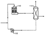
気液反応を効率的に行う技術として、特許文献2には、図7に示すように、ベンゼンをシクロヘキサンにする気液反応において、ベンゼンを含む液体を収容した反応器110から、ポンプ105によりこの液体を抜き出して高せん断装置140に供給し、この高せん断装置140でこの液体に平均気泡直径100μmの水素ガス気泡を含有させて反応器110に還流する気液反応装置が開示されている。また、特許文献3には、図8に示すように、芳香族ニトロ化合物を芳香族アミン化合物にする気液反応において、芳香族ニトロ化合物溶液208をバイアル瓶209からフィルター207を通して抜き出し、水素ガスを導入して水素マイクロバブルを含有させ、触媒固定官に導入して水素化反応を進行させた後、バイアル瓶209に還流する気液反応装置が開示されている。
The above-mentioned batch method or continuous process method is advantageous as a method for carrying out a gas-liquid reaction in a large amount and efficiently on an industrial scale, but in order to increase the efficiency of the gas-liquid reaction, a liquid phase is used in a reaction gas atmosphere. It is necessary to vigorously stir in order to increase the contact area between the gas phase and the gas phase. Further, in order to increase the efficiency of the gas-liquid reaction, it is necessary to carry out the gas-liquid reaction under high temperature and high pressure.
As a technique for efficiently performing a gas-liquid reaction, as shown in FIG. 7,
しかしながら、上記特許文献2のような気液反応装置では、気液反応を高い効率で行うためには、反応器110内の圧力を通常5MPa〜20MPaという高圧とする必要があるが、高せん断装置140を含むベンゼンを含む液体の循環経路をこのような高圧力に維持して運転するのは難しく、装置の設置・運転・維持を経済的・効率的に行うのは難しい。
However, in a gas-liquid reactor as in
また、上記特許文献3のような気液反応装置は、水素マイクロバブルを含有させた芳香族ニトロ化合物溶液208を触媒固定官を通して気液反応を行うため大量に処理することが難しく、また、気液反応を高温・高圧下で行うことが難しいため、工業規模で大量かつ効率的に気液反応を行う装置として適当ではない。
Further, in a gas-liquid reactor as in
本発明者等は、工業規模で大量かつ効率的に気液反応を行うことができ、しかも、装置の設置・運転・維持を経済的・効率的に行うことのできる気液反応装置及びこの気液反応装置を用いた気液反応方法を鋭意研究し本発明を成したものである。 The present inventors can carry out a gas-liquid reaction in a large amount and efficiently on an industrial scale, and can economically and efficiently install, operate, and maintain the device, and a gas-liquid reaction device and this gas. The present invention has been made by diligently researching a gas-liquid reaction method using a liquid reactor.
本発明の気液反応装置及びこの気液反応装置を用いた気液反応方法の課題は、工業規模で大量かつ効率的に気液反応を行うことができ、しかも、装置の設置・運転・維持を経済的・効率的に行うことのできる気液反応装置及びこの気液反応装置を用いた気液反応方法を提供することにある。 The problem of the gas-liquid reaction device of the present invention and the gas-liquid reaction method using this gas-liquid reaction device is that a large amount of gas-liquid reaction can be efficiently performed on an industrial scale, and the device is installed, operated, and maintained. It is an object of the present invention to provide a gas-liquid reaction apparatus capable of economically and efficiently performing the above, and a gas-liquid reaction method using the gas-liquid reactor.
上記課題を解決するため、本発明の気液反応装置及びこの気液反応装置を用いた気液反応方法は、気液反応装置の反応槽内にはマイクロナノバブル発生装置を設けると共に、このマイクロナノバブル発生装置に、反応槽の液相に存在する反応物質含有液体及び反応槽の気相に存在する反応気体を供給し、反応気体のマイクロナノバブルを含有させた反応物質含有液体を液相に供給することを特徴とするものである。 In order to solve the above problems, in the gas-liquid reactor of the present invention and the gas-liquid reaction method using the gas-liquid reactor, a micro-nano bubble generator is provided in the reaction vessel of the gas-liquid reactor, and the micro-nano bubbles are provided. The reactant-containing liquid existing in the liquid phase of the reaction tank and the reaction gas existing in the gas phase of the reaction tank are supplied to the generator, and the reactant-containing liquid containing micro-nanobubbles of the reaction gas is supplied to the liquid phase. It is characterized by that.
さらに、マイクロナノバブル発生装置としては、図6にその概要を示して後で説明するような、多量のマイクロナノバブルを経済的に発生することのできる液流方式のものを用い、このマイクロナノバブル発生装置に反応槽の液相に存在する反応物質含有液体を加圧して供給し、これにより生じる負圧により反応槽の気相から反応気体を吸い込むようにすることにより、前記課題の解決を一層図ることができる。 Further, as the micro-nano bubble generator, a liquid flow type device capable of economically generating a large amount of micro-nano bubbles, which is outlined in FIG. 6 and described later, is used, and this micro-nano bubble generator is used. To further solve the above problems, the reactant-containing liquid existing in the liquid phase of the reaction tank is pressurized and supplied, and the reaction gas is sucked from the gas phase of the reaction tank by the negative pressure generated thereby. Can be done.
本発明の気液反応装置及びこの気液反応装置を用いた気液反応方法は、次のような優れた効果を奏するものである。 The gas-liquid reaction device of the present invention and the gas-liquid reaction method using this gas-liquid reaction device have the following excellent effects.
バッチ式または連続式プロセス法の気液反応を採用し、気密に密封された反応槽内で、高温・高圧下で気液反応を行うことにより、気液反応を工業規模で大量かつ効率的に行うことができる。 By adopting the gas-liquid reaction of the batch type or continuous process method and performing the gas-liquid reaction at high temperature and high pressure in an airtightly sealed reaction tank, the gas-liquid reaction can be carried out in large quantities and efficiently on an industrial scale. It can be carried out.
また、マイクロナノバブル発生装置を用いて、反応気体のマイクロナノバブルを反応物質含有液体に含有させることにより、激しい撹拌を行うことなく液相と気相との接触面積を大きくでき、気液反応を効率的・経済的に行うことができる。 Further, by incorporating micro-nano bubbles of the reaction gas into the reactant-containing liquid using a micro-nano bubble generator, the contact area between the liquid phase and the gas phase can be increased without vigorous stirring, and the gas-liquid reaction can be made efficient. Can be done economically and economically.
また、反応気体のマイクロナノバブルを含有させた反応物質含有液体を、マイクロナノバブル発生装置から液相に供給することにより、液相を撹拌することができ、気液反応を効率的・経済的に行うことができる。 Further, by supplying the reactant-containing liquid containing the micro-nano bubbles of the reaction gas to the liquid phase from the micro-nano bubble generator, the liquid phase can be agitated, and the gas-liquid reaction can be efficiently and economically performed. be able to.
また、マイクロナノバブル発生装置を反応槽内に設けることにより、反応槽内を安定的に高圧力に維持でき、装置の設置・運転・維持を経済的・効率的に行うことができる。さらに、マイクロナノバブル発生装置として液流方式のものを用い、このマイクロナノバブル発生装置に反応槽の液相に存在する反応物質含有液体を加圧して供給し、これにより生じる負圧により反応槽の気相から反応気体を吸い込み、反応気体のマイクロナノバブルを含有させた反応物質含有液体を液相に供給することにより、液相の反応物質含有液体を一層効率的・経済的に撹拌することができる。 Further, by providing the micro-nano bubble generator in the reaction vessel, the inside of the reaction vessel can be stably maintained at a high pressure, and the apparatus can be installed, operated and maintained economically and efficiently. Furthermore, a liquid flow type is used as the micro-nano bubble generator, and the reactant-containing liquid existing in the liquid phase of the reaction tank is pressurized and supplied to this micro-nano bubble generator, and the negative pressure generated by this pressurizes and supplies the air in the reaction tank. By sucking the reaction gas from the phase and supplying the reactant-containing liquid containing the micro-nanobubbles of the reaction gas to the liquid phase, the reactant-containing liquid in the liquid phase can be agitated more efficiently and economically.
また、このようなマイクロナノバブル発生装置を用いることにより、マイクロナノバブルの個数平均直径及び総バブル数を、マイクロナノバブル発生装置に供給される反応物質含有液体の圧力、流量だけでなく、反応槽の気相に存在する反応気体の圧力によっても調整することができる。 Further, by using such a micro-nano bubble generator, the average diameter of the number of micro-nano bubbles and the total number of bubbles can be determined not only by the pressure and flow rate of the reactant-containing liquid supplied to the micro-nano bubble generator, but also by the gas in the reaction tank. It can also be adjusted by the pressure of the reactive gas present in the phase.
以下、本発明の実施形態を、添付の図面も参照しながら詳細に説明するが、本発明はこれらに限定されるものではない。以下の説明においては、還元反応の代表例である有機化合物の水素添加反応を行なう気液反応について主として説明するが、本発明の気液反応装置及びこの気液反応装置を用いた気液反応方法は、これらの油脂、脂肪酸、合成樹脂等の有機化学物質または無機化学物質を使用する気液反応に使用することも当然可能である。 Hereinafter, embodiments of the present invention will be described in detail with reference to the accompanying drawings, but the present invention is not limited thereto. In the following description, a gas-liquid reaction in which a hydrogenation reaction of an organic compound is carried out, which is a typical example of a reduction reaction, will be mainly described, but the gas-liquid reaction apparatus of the present invention and a gas-liquid reaction method using this gas-liquid reaction apparatus will be described. Can of course be used in gas-liquid reactions using organic or inorganic chemical substances such as these fats and oils, fatty acids, and synthetic resins.
1.本発明の一般的な事項
まず、本発明の気液反応装置及びこの気液反応装置を用いた気液反応方法(以下、「本発明の装置及び方法」ともいう。)の一般的な事項について説明する。
1. 1. General Matters of the Present Invention First, regarding the general matters of the gas-liquid reactor of the present invention and the gas-liquid reaction method using the gas-liquid reactor (hereinafter, also referred to as "the device and method of the present invention"). explain.
本発明の装置及び方法は、バッチ式または連続式プロセス法の気液反応であって、気密に密封された反応槽に、反応物質を含有する液体(反応物質含有液体)及び加圧された反応気体を含有する気体(反応気体)を供給して液相及び気相を形成し、気液反応を行うものである。また、気液反応の反応効率を向上させるために、気液反応を高温・高圧下で行うのが好ましい。 The apparatus and method of the present invention is a gas-liquid reaction of a batch type or continuous process method, in which a liquid containing a reactant (liquid containing a reactant) and a pressurized reaction are placed in a tightly sealed reaction vessel. A gas containing a gas (reaction gas) is supplied to form a liquid phase and a gas phase, and a gas-liquid reaction is carried out. Further, in order to improve the reaction efficiency of the gas-liquid reaction, it is preferable to carry out the gas-liquid reaction at a high temperature and a high pressure.
〇気液反応
本発明の装置及び方法が適用できる気液反応としては、特に制限はなく、通常、高温下または高温・高圧下で行われる既知の気液反応に適用することができる。
例えば、ラジカルカルボニル化反応、オレフィンのヒドロホルミル化反応、直接フッ素化反応、酸素酸化反応(アルコールからアルデヒドを得る反応、アルケンからエポキシを得る反応、光一重項酸素酸化反応、エステルのα位酸化反応等)、水素化反応(還元糖の水素添加による糖アルコール製造、オレフィンの水素化反応、カルボニル化合物の水素化反応、シアノ基の水素化反応、天然油脂の不飽和グリセリドの水素添加による硬化油の製造、不飽和脂肪酸をニッケル触媒により水素添加する反応等)、アルカンの光ハロゲン化反応、Heckカルボニル化反応に適用できる。
〇 Gas-liquid reaction The gas-liquid reaction to which the apparatus and method of the present invention can be applied is not particularly limited, and can be applied to a known gas-liquid reaction usually carried out under high temperature or high temperature / high pressure.
For example, radical carbonylation reaction, hydroformation reaction of olefin, direct hydrogenation reaction, oxygen oxidation reaction (reaction to obtain aldehyde from alcohol, reaction to obtain epoxy from alkene, photomonomorphic oxygen oxidation reaction, α-position oxidation reaction of ester, etc. ), Hydrogenation reaction (production of sugar alcohol by hydrogenation of reduced sugar, hydrogenation reaction of olefin, hydrogenation reaction of carbonyl compound, hydrogenation reaction of cyano group, production of hardened oil by hydrogenation of unsaturated glyceride of natural fats and oils , Reaction of hydrogenating unsaturated fatty acids with a nickel catalyst, etc.), photohalogenation reaction of alkenes, Heck carbonylation reaction.
〇反応物質を含有する液体(反応物質含有液体)
本発明の装置及び方法において用いられる反応物質含有液体は、反応物質のみを含有していてもよいし、反応物質及び溶媒を含有していてもよい。
〇 Liquid containing reactant (liquid containing reactant)
The reactant-containing liquid used in the apparatus and method of the present invention may contain only the reactant or may contain the reactant and the solvent.
溶媒としては、水、有機溶媒、イオン液体(イオン性液体、イオン性流体、常温融解塩とも称される)、液体の無機化合物等の1種または2種以上を用いることができる。有機溶媒としては、ヘキサン等の脂肪族系炭化水素、ベンゼン、トルエン、キシレン等の芳香族炭化水素、アセトン、ジエチルケトン、メチルエチルケトン等のケトン類、ブチルアルデヒド等のアルデヒド類、ジエチルエーテル、ジブチルエーテル、ジイソブチルエーテル、テトラヒドロフラン、ジオキサン等のエーテル類、酢酸エチル、酢酸ブチル、ジ−n−オクチルフタレート等のエステル類、トリエチルアミン、ピロリジン、ピペリジン等のアミン類、ジメチルホルムアミド等のアミド類、ジメチルスルホキシド等のスルホキシド類、メタノール、エタノール、プロパノール、イソプロパノール等のアルコール類、エチレングリコール、プロパンジオール、ブタンジオール等のジオール類、アセトニトリル等のニトリル類、ピリジン等の複素芳香族化合物、四塩化炭素、クロロホルム、ジクロロメタン、ジクロエタン等のハロゲン溶媒、酢酸、蟻酸等のカルボン酸類、スルホン酸類、フロリナート(登録商標)等のフッ素系不活性液体が挙げられ、これらの2種以上の任意の割合の混合溶媒を用いることもできる。液体の無機化合物としては、硫酸、リン酸、亜リン酸等のリン酸類、硝酸、過酸化水素水等が挙げられる。溶媒としては、中でも、水系溶媒と有機溶媒が好ましく、更に好ましくは芳香族炭化水素、炭化水素類やアルコール類が好ましく、特に芳香族炭化水素が好適である。 As the solvent, one or more kinds such as water, an organic solvent, an ionic liquid (also referred to as an ionic liquid, an ionic fluid, and a room temperature molten salt), and a liquid inorganic compound can be used. Examples of the organic solvent include aliphatic hydrocarbons such as hexane, aromatic hydrocarbons such as benzene, toluene and xylene, ketones such as acetone, diethyl ketone and methyl ethyl ketone, aldehydes such as butyl aldehyde, diethyl ether and dibutyl ether. Ethers such as diisobutyl ether, tetrahydrofuran and dioxane, esters such as ethyl acetate, butyl acetate and di-n-octylphthalate, amines such as triethylamine, pyrrolidine and piperidine, amides such as dimethylformamide, and sulfoxides such as dimethylsulfoxide. Classes, alcohols such as methanol, ethanol, propanol and isopropanol, diols such as ethylene glycol, propanediol and butanediol, nitriles such as acetonitrile, heteroaromatic compounds such as pyridine, carbon tetrachloride, chloroform, dichloromethane and dichloroethan. Examples thereof include halogen solvents such as halogen solvents such as, carboxylic acids such as acetic acid and formic acid, sulfonic acids, and fluorine-based inert liquids such as Florinate (registered trademark), and a mixed solvent of any ratio of two or more of these can also be used. Examples of the liquid inorganic compound include phosphoric acids such as sulfuric acid, phosphoric acid and phosphorous acid, nitric acid, hydrogen peroxide solution and the like. As the solvent, among them, an aqueous solvent and an organic solvent are preferable, aromatic hydrocarbons, hydrocarbons and alcohols are more preferable, and aromatic hydrocarbons are particularly preferable.
溶媒を用いる場合には、その使用量に制限はなく、用いる反応物質の濃度が溶媒1リットルに対して通常0.001モル以上、好ましくは0.02モル以上、さらに好ましくは0.1モル以上で、20モル以下、好ましくは10モル以下、さらに好ましくは5モル以下となるような量の溶媒を用いることが好ましい。溶媒の量が上記の範囲よりも多いと生産性が低下し、少ないと触媒あるいは反応物質を溶解させてしまう点で不利となる。 When a solvent is used, the amount used is not limited, and the concentration of the reactant used is usually 0.001 mol or more, preferably 0.02 mol or more, and more preferably 0.1 mol or more with respect to 1 liter of the solvent. Therefore, it is preferable to use an amount of the solvent such that the amount is 20 mol or less, preferably 10 mol or less, and more preferably 5 mol or less. If the amount of the solvent is larger than the above range, the productivity is lowered, and if the amount of the solvent is smaller than the above range, the catalyst or the reactant is dissolved, which is disadvantageous.
〇反応気体を含有する気体(反応気体)
反応気体としては、オゾン、水素、ヘリウム、フッ素、塩素、一酸化炭素、二酸化炭素、二酸化硫黄、塩化水素ガス、アンモニアガス、メタン、エタン、プロパン、エチレンガス、アセチレンガス等が挙げられ、酸素は一重項酸素及び三重項酸素が挙げられる。また、これらの混合ガス、あるいはこれらの反応ガスと他の気体との混合ガスを用いてもよい。
〇 Gas containing reactive gas (reactive gas)
Examples of the reaction gas include ozone, hydrogen, helium, fluorine, chlorine, carbon monoxide, carbon dioxide, sulfur dioxide, hydrogen chloride gas, ammonia gas, methane, ethane, propane, ethylene gas, acetylene gas and the like. Singlet oxygen and triplet oxygen can be mentioned. Further, a mixed gas of these or a mixed gas of these reaction gases and another gas may be used.
気体成分中の反応気体の濃度については、特に制限はないが、体積割合で0.01〜100%の範囲から選択され、好ましくは0.1%以上、より好ましくは5%以上で、特に好ましくは10%以上である。反応気体の濃度が上記範囲よりも低いと十分な反応効率を得ることが難しくなる。 The concentration of the reactive gas in the gas component is not particularly limited, but is selected from the range of 0.01 to 100% by volume, preferably 0.1% or more, more preferably 5% or more, and particularly preferably. Is 10% or more. If the concentration of the reaction gas is lower than the above range, it will be difficult to obtain sufficient reaction efficiency.
〇触媒
本発明の装置及び方法では、気液反応に、触媒を使用してもよいし、使用しなくてもよいが、通常は、触媒を使用した方が気液反応を効率的に行えるため好ましい。
〇Catalyst In the apparatus and method of the present invention, a catalyst may or may not be used for the gas-liquid reaction, but usually, the gas-liquid reaction can be performed more efficiently by using the catalyst. preferable.
触媒としては、周期律表第4〜12族の元素(金属)及びランタノイドから選ばれる元素(金属)の少なくとも一種を含有するものを好適に用いることができ、また、触媒は、シリカ、アルミナ、シリカアルミナ、ゼオライト、活性炭等の多孔質材料の表面に担持させて用いることができる。例えば、還元糖の水素添加反応を行う場合には、ラネーニッケル触媒等を用いることができる。
As the catalyst, those containing at least one of the elements (metals) of
触媒を使用する場合、好適には、均一系触媒を、反応槽内の液相に存在する反応物質含有液体に含有させて用いる。触媒の使用量としては、特に制限はないが、反応物質に対して有効成分量として0.1ppm以上、特に1ppm以上、10%以下、特に1%以下とすることが好ましい。 When a catalyst is used, a homogeneous catalyst is preferably used by being contained in a reactant-containing liquid present in the liquid phase in the reaction vessel. The amount of the catalyst used is not particularly limited, but is preferably 0.1 ppm or more, particularly 1 ppm or more, 10% or less, and particularly 1% or less as the amount of the active ingredient with respect to the reactant.
〇反応条件
本発明の装置及び方法は、上記のように、バッチ式または連続式プロセス法の気液反応を採用し、気密に密封された反応槽内で、通常、高温・高圧下で気液反応を行うものであるが、反応槽内の温度、反応槽内の圧力、反応時間等の条件については、気液反応、反応物質、反応気体の種類等に応じて、最適な範囲を適宜設定することができる。
〇 Reaction conditions As described above, the apparatus and method of the present invention employ a gas-liquid reaction of batch or continuous process methods, and gas-liquid reactions are usually performed at high temperature and high pressure in an airtightly sealed reaction vessel. Although the reaction is carried out, the optimum range of conditions such as the temperature in the reaction vessel, the pressure in the reaction vessel, and the reaction time is appropriately set according to the gas-liquid reaction, the reactant, the type of reaction gas, etc. can do.
例えば、還元糖の水素添加反応を行う場合には、反応槽内の温度の下限値を好ましくは20℃以上、より好ましくは50℃以上さらに好ましくは80℃以上、特に好ましくは110℃以上とし、上限値を好ましくは350℃以下、より好ましくは300℃以下、さらに好ましくは250℃以下、特に好ましくは200℃以下とし、水素圧力の下限値を好ましくは0.1MPa以上、より好ましくは0.5MPa以上、さらに好ましくは1MPa以上、特に好ましくは5MPa以上とし、上限値を好ましくは30MPa以下、より好ましくは25MPa以下、さらに好ましくは20MPa以下とし、反応時間を好ましくは30分以上9時間以下とする。 For example, when the hydrogenation reaction of a reducing sugar is carried out, the lower limit of the temperature in the reaction vessel is preferably 20 ° C. or higher, more preferably 50 ° C. or higher, still more preferably 80 ° C. or higher, and particularly preferably 110 ° C. or higher. The upper limit is preferably 350 ° C. or lower, more preferably 300 ° C. or lower, further preferably 250 ° C. or lower, particularly preferably 200 ° C. or lower, and the lower limit of hydrogen pressure is preferably 0.1 MPa or higher, more preferably 0.5 MPa or lower. The above is more preferably 1 MPa or more, particularly preferably 5 MPa or more, the upper limit is preferably 30 MPa or less, more preferably 25 MPa or less, still more preferably 20 MPa or less, and the reaction time is preferably 30 minutes or more and 9 hours or less.
2.本発明の第1の特徴
本発明の装置及び方法は、上記のようなバッチ式または連続式プロセス法の気液反応を行うが、この反応において、反応槽内に設けたマイクロナノバブル発生装置により、反応槽の液相に存在する反応物質含有液体に、反応槽の気相に存在する反応気体のマイクロナノバブルを含有させ、これを液相に供給することを第1の特徴とするものである。
2. The first feature of the present invention The apparatus and method of the present invention carry out the gas-liquid reaction of the batch type or continuous process method as described above, and in this reaction, the micro-nano bubble generator provided in the reaction vessel is used. The first feature is that the reactant-containing liquid existing in the liquid phase of the reaction tank contains micro-nano bubbles of the reaction gas existing in the gas phase of the reaction tank and is supplied to the liquid phase.
このように、バッチ式または連続式プロセス法の気液反応を採用し、気密に密封された反応槽内で、高圧下好ましくは高温・高圧下で気液反応を行うことにより、気液反応を工業規模で大量かつ効率的に行うことができる。 In this way, the gas-liquid reaction of the batch type or continuous process method is adopted, and the gas-liquid reaction is carried out under high pressure, preferably at high temperature and high pressure in an airtightly sealed reaction tank. It can be done in large quantities and efficiently on an industrial scale.
また、マイクロナノバブル発生装置を用いて、反応気体のマイクロナノバブルを反応物質含有液体に含有させることにより、激しい撹拌を行うことなく液相と気相との接触面積を大きくでき、気液反応を効率的・経済的に行うことができる。 Further, by incorporating micro-nano bubbles of the reaction gas into the reactant-containing liquid using a micro-nano bubble generator, the contact area between the liquid phase and the gas phase can be increased without vigorous stirring, and the gas-liquid reaction can be made efficient. Can be done economically and economically.
また、反応気体のマイクロナノバブルを含有させた反応物質含有液体を、マイクロナノバブル発生装置から液相に供給することにより、特に培養槽撹拌機を設置しなくても液相を適度に撹拌することができ、気液反応を効率的・経済的に行うことができる。 Further, by supplying the reactant-containing liquid containing micro-nano bubbles of the reaction gas from the micro-nano bubble generator to the liquid phase, the liquid phase can be appropriately agitated without installing a culture tank stirrer. It is possible to carry out gas-liquid reaction efficiently and economically.
また、マイクロナノバブル発生装置を反応槽内に設けることにより、マイクロナノバブル発生装置を反応槽外部に設ける場合に比べ、反応槽内を安定的に高圧力に維持でき、装置の設置・運転・維持を経済的・効率的に行うことができる。 Further, by providing the micro-nano bubble generator inside the reaction vessel, the inside of the reaction vessel can be stably maintained at a high pressure as compared with the case where the micro-nano bubble generator is provided outside the reaction vessel, and the installation, operation and maintenance of the apparatus can be performed. It can be done economically and efficiently.
〇反応気体のマイクロナノバブル
本発明では、反応物質含有液体に反応気体のマイクロナノバブルを含有させるが、本発明の「マイクロナノバブル」とは、「マイクロバブル」及び/又は「ナノバブル」を意味する。「通常の気泡」は水中を急速に上昇して表面で破裂して消えるのに対し、「マイクロバブル」といわれる直径50μm以下の微小気泡は、水中で縮小していって消滅し、この際に、フリーラジカルと共に、直径100nm以下の極微小気泡である「ナノバブル」を発生し、この「ナノバブル」はある程度の長時間水中に残存する。
〇 Micro-nano bubbles of reactive gas In the present invention, micro-nano bubbles of reactive gas are contained in the reactant-containing liquid, and the “micro-nano bubbles” of the present invention mean “micro-bubbles” and / or “nano-bubbles”. While "ordinary bubbles" rapidly rise in water and burst at the surface and disappear, microbubbles with a diameter of 50 μm or less, called "microbubbles," shrink and disappear in water. Along with free radicals, "nano bubbles", which are microbubbles having a diameter of 100 nm or less, are generated, and these "nano bubbles" remain in water for a certain period of time.
本発明においては、個数平均直径が100μm以下の気泡を「マイクロバブル」といい、個数平均直径が1μm以下の気泡を「ナノバブル」という。マイクロナノバブル、ナノバブル等の気泡を測定する方法としては、電気的検知帯法、共振式質量測定法、粒子軌跡解析法等が一般に用いられている。 In the present invention, bubbles having a number average diameter of 100 μm or less are referred to as “micro bubbles”, and bubbles having a number average diameter of 1 μm or less are referred to as “nano bubbles”. As a method for measuring bubbles such as micro-nano bubbles and nano bubbles, an electric detection band method, a resonance type mass measurement method, a particle trajectory analysis method, and the like are generally used.
極微小気泡である「ナノバブル」は、「ウルトラファインバブル」とも呼ばれる。なお、現在、ISO(国際標準化機構)において、ファインバブル技術に関する国際標準の作成が検討されており、国際標準が作成されれば、現在一般的に用いられている「ナノバブル」との呼称が、「ウルトラファインバブル」に統一される可能性もある。 "Nano bubbles", which are micro bubbles, are also called "ultra fine bubbles". At present, ISO (International Organization for Standardization) is considering the creation of an international standard for fine bubble technology, and if an international standard is created, the name "nano bubble" that is generally used at present will be used. There is a possibility that it will be unified into "ultra fine bubble".
マイクロナノバブルの個数平均直径が大きすぎると、マイクロナノバブルが液相中で上昇するに伴ってマイクロナノバブル内の圧力低下によってマイクロナノバブルが膨張し、その結果、マイクロナノバブルの比表面積(単位重量あたりの表面積)が増加することによって気液反応の促進効果が低くなる。 Number of micro-nano bubbles If the average diameter is too large, the micro-nano bubbles will expand due to the pressure drop in the micro-nano bubbles as the micro-nano bubbles rise in the liquid phase, resulting in the specific surface area of the micro-nano bubbles (surface area per unit weight). ) Decreases the effect of promoting the gas-liquid reaction.
また、マイクロナノバブルの比表面積を増加させるためには、反応物質と接触させる反応物質含有液体中の単位体積当たりのマイクロナノバブルの数(以下「総バブル数」という。)も重要となる。反応物質含有液体1mLあたりの総バブル数が105個以上、好ましくは106〜109個、より好ましくは107〜1010個となるように発生させることが好ましい。
Further, in order to increase the specific surface area of the micro-nano bubbles, the number of micro-nano bubbles per unit volume in the reactant-containing liquid to be brought into contact with the reactant (hereinafter referred to as "total number of bubbles") is also important. Reactant total bubble per-containing
これらのマイクロナノバブルの個数平均直径及び総バブル数は、気液反応、反応物質、反応気体の種類等に応じて、最適な範囲を適宜設定することができ、後で述べるマイクロナノバブル発生装置の構造、発生条件等により調節・設定することができる。 Optimal ranges can be appropriately set for the average diameter of the number of these micro-nano bubbles and the total number of bubbles according to the gas-liquid reaction, the reactant, the type of reaction gas, etc., and the structure of the micro-nano bubble generator described later. , Can be adjusted and set according to the generation conditions.
反応物質含有液体に反応気体のマイクロナノバブルを含有させることにより、反応物質含有液体中に反応気体を長期間残留させることができ、気液反応における物質移動の制限を減少させることができる。マイクロナノバブルの個数平均直径が小さくても反応速度に対して悪影響はないが、反応気体の反応物質含有液体の飽和度には制限があるため、マイクロナノバブルの個数平均直径が小さすぎても経済的には非効率となる。また総バブル数はマイクロナノバブル発生装置の設定条件上発生させることが可能であり、反応物質との反応にあたりマイクロバナノブルが安定に存在できれば、多ければ多いほど好ましい。 By including micro-nanobubbles of the reaction gas in the reactant-containing liquid, the reaction gas can remain in the reactant-containing liquid for a long period of time, and the restriction of mass transfer in the gas-liquid reaction can be reduced. A small number average diameter of micro-nano bubbles does not adversely affect the reaction rate, but it is economical if the average number of micro-nano bubbles is too small because the saturation of the reactant-containing liquid in the reaction gas is limited. Will be inefficient. Further, the total number of bubbles can be generated under the setting conditions of the micro-nano bubble generator, and it is preferable that the number of micro-banano bubbles can be stably present in the reaction with the reactant.
〇マイクロナノバブル発生装置
マイクロナノバブル発生装置としては、公知あるいは市販されている装置を用いることができ、例えば、ある程度の高圧で十分な量の気体を水中に溶解させた後、その圧力を解放してやることで溶解した気体の過飽和条件を作り出す「加圧溶解型マイクロナノバブル発生装置」や、液流を起こして液体と気体からなる混合流体をループ状の流れとして撹拌混合し、液流によって発生した乱流により気泡が細分化する現象を利用した「ループ流式バブル発生ノズル」等を用いることができる。
〇 Micro-nano bubble generator As the micro-nano bubble generator, a known or commercially available device can be used. For example, a sufficient amount of gas is dissolved in water at a certain high pressure and then the pressure is released. A "pressurized dissolution type micro-nano bubble generator" that creates hypersaturation conditions for the gas dissolved in It is possible to use a "loop flow type bubble generation nozzle" or the like that utilizes the phenomenon that the bubbles are subdivided by the gas.
3.本発明の第2の特徴
本発明の装置及び方法は、反応槽内に設けるマイクロナノバブル発生装置として液流方式のものを用い、このマイクロナノバブル発生装置に反応槽の液相に存在する反応物質含有液体を加圧して供給し、これにより生じる負圧により反応槽の気相から反応気体を吸い込み、反応気体のマイクロナノバブルを含有させた反応物質含有液体を液相に供給することを第2の特徴とするものである。
3. 3. The second feature of the present invention The apparatus and method of the present invention use a liquid flow type as a micro-nano bubble generator provided in the reaction vessel, and the micro-nano bubble generator contains a reactant existing in the liquid phase of the reaction vessel. The second feature is that the liquid is pressurized and supplied, the reaction gas is sucked from the gas phase of the reaction tank by the negative pressure generated by this, and the reactant-containing liquid containing micro-nano bubbles of the reaction gas is supplied to the liquid phase. Is to be.
このようなマイクロナノバブル発生装置を用いることにより、反応気体のマイクロナノバブルを含有させた反応物質含有液体の液相への供給を効率的・経済的に行うことができ、液相の反応物質含有液体を一層効率的・経済的に撹拌することができる。 By using such a micro-nano bubble generator, it is possible to efficiently and economically supply the reactant-containing liquid containing the micro-nano bubbles of the reaction gas to the liquid phase, and the liquid phase of the reactant-containing liquid can be supplied. Can be agitated more efficiently and economically.
さらに、マイクロナノバブルの個数平均直径及び総バブル数を、マイクロナノバブル発生装置に供給される反応物質含有液体の圧力、流量だけでなく、反応槽の気相に存在する反応気体の圧力によっても調整することができる。 Further, the average diameter of the number of micro-nano bubbles and the total number of bubbles are adjusted not only by the pressure and flow rate of the reactant-containing liquid supplied to the micro-nano bubble generator, but also by the pressure of the reaction gas existing in the gas phase of the reaction vessel. be able to.
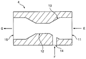
この液流方式のマイクロナノバブル発生装置について、図6を用いて説明する。
マイクロナノバブル発生装置4としては、液流方式、すなわち、液流によりマイクロナノバブルを発生させる方式のものを用いることができ、この液流方式のマイクロナノバブル発生装置の代表的なものとしては、ノズル型のマイクロナノバブル発生装置を挙げることができる。このノズル型のマイクロナノバブル発生装置は図6に示すようなものである。
This liquid flow type micro-nano bubble generator will be described with reference to FIG.
As the
図6において、反応槽の液相に存在する反応物質含有液体E(以下、「液体E」ともいう。)は、加圧されてノズルの入口部11から供給され、管の縮径に伴って流速を上げていき、のど部12で乱流を発生させる。反応槽の気相に存在する反応気体Fは、液体Eの流れによって生じる負圧により、気体入口14から吸引され、吸引部13において液体Eと混合され、のど部12での乱流によりマイクロナノバブルとなる。このようにして形成された、反応気体のマイクロナノバブルを含有する反応物質含有液体Gは、出口部15から、液相に供給される。
In FIG. 6, the reactant-containing liquid E (hereinafter, also referred to as “liquid E”) existing in the liquid phase of the reaction tank is pressurized and supplied from the
4.本発明の実施形態
つぎに、図1〜5を用いて、本発明の第1実施形態(図1)、第2実施形態(図2)、第3実施形態(図3)、第4実施形態(図4)及び第5実施形態(図5)について説明する。
4. Embodiment of the present invention Next, using FIGS. 1 to 5, the first embodiment (FIG. 1), the second embodiment (FIG. 2), the third embodiment (FIG. 3), and the fourth embodiment of the present invention are used. FIG. 4 and a fifth embodiment (FIG. 5) will be described.
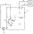
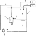
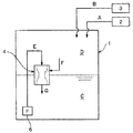
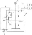
第1実施形態乃至第5実施形態ではマイクロナノバブル発生装置4としてノズル型のものを用いているが、このマイクロナノバブル発生装置4が、第1実施形態及び第5実施形態では反応槽1の気相Dに設けられており、第2実施形態では反応槽1の液相Cに設けられており、第3実施形態及び第4実施形態では反応槽1の気相D及び液相Cに跨がって設けられている。第1実施形態及び第5実施形態のように、マイクロナノバブル発生装置4を反応槽1の気相Dに設ける場合には、マイクロナノバブル発生装置4の出口に、反応気体Bのマイクロナノバブルを含有させた反応物質含有液体Aを、液相C内に導いて供給するための配管8を設ける。
In the first to fifth embodiments, a nozzle type
また、第4実施形態では、反応槽1の液相Cに存在する反応物質含有液体Eをマイクロナノバブル発生装置4に供給するためのポンプとして、他の実施形態のように、反応槽1の外部に設けたポンプ5を用いず、反応槽1の内部に設けたポンプを用いるものであって、例えばポンプインペラ(ポンプ羽根車)を反応槽1の内部に配置するようにしたインターナルポンプ6を用いている。第4実施形態では、マイクロナノバブル発生装置4を反応槽1の気相D及び液相Cに跨がって設けているが、もちろん、第1実施形態及び第5実施形態のように、反応槽1の気相Dに設けることもできるし、第2実施形態のように、反応槽1の液相Cに設けることもできる。
Further, in the fourth embodiment, as a pump for supplying the reactant-containing liquid E existing in the liquid phase C of the reaction tank 1 to the
また、第5実施形態は、第1実施形態の気液反応装置に、液相Cの反応物質含有液体Aを撹拌するための、反応槽撹拌機7を設けたものである。
Further, in the fifth embodiment, the gas-liquid reactor of the first embodiment is provided with a
まず、図1を参照しながら、本発明の第1実施形態について説明する。
第1実施形態では、次のようにして、反応物質を含有する液体(反応物質含有液体)Aと、反応気体を含有する気体(反応気体)Bとの気液反応を行う。
1)気密に密封された反応槽1に、液体供給装置2から、反応物質を含有する液体(反応物質含有液体)Aを供給し、加圧気体供給装置3から、加圧された反応気体を含有する気体(反応気体)Bを供給し、反応槽の液相C及び気相Dを形成する。
2)反応槽内の温度を、ヒーター等の加熱手段(図示せず)により所定温度まで上昇させ、また、反応槽内の圧力を、加圧気体供給装置3により所定圧力まで上昇させて、反応槽内を高温・高圧状態として、気液反応を開始する。
3)ポンプ5により、反応槽1の液相Cから反応物質含有液体Aを抜き出し、加圧して、
反応槽1の気相Dに設けた、ノズル型のマイクロナノバブル発生装置4に供給する。
4)反応物質含有液体Aの流れによって生じる負圧により、マイクロナノバブル発生装置4に、反応槽1の気相Dから反応気体Aを吸い込む。
5)このようにして、反応気体Bのマイクロナノバブルを含有させた反応物質含有液体Aは、マイクロナノバブル発生装置4の出口に設けられた配管8を通じて、液相C内に導かれて供給される。
First, the first embodiment of the present invention will be described with reference to FIG.
In the first embodiment, a gas-liquid reaction is carried out between a liquid containing a reactant (reactant-containing liquid) A and a gas containing a reaction gas (reactive gas) B as follows.
1) The
2) The temperature in the reaction vessel is raised to a predetermined temperature by a heating means (not shown) such as a heater, and the pressure in the reaction vessel is raised to a predetermined pressure by the pressurized
3) The reactant-containing liquid A is extracted from the liquid phase C of the reaction tank 1 by the pump 5 and pressurized.
It is supplied to the nozzle-type
4) Due to the negative pressure generated by the flow of the reactant-containing liquid A, the reaction gas A is sucked into the
5) In this way, the reactant-containing liquid A containing the micro-nano bubbles of the reaction gas B is guided and supplied into the liquid phase C through the
第1実施形態では、バッチ式プロセス法の気液反応を採用し、気密に密封された反応槽1内で、高温・高圧下で気液反応を行うことにより、気液反応を工業規模で大量かつ効率的に行うことができる。 In the first embodiment, the gas-liquid reaction of the batch process method is adopted, and the gas-liquid reaction is carried out under high temperature and high pressure in the airtightly sealed reaction tank 1, so that the gas-liquid reaction is carried out in large quantities on an industrial scale. And it can be done efficiently.
また、マイクロナノバブル発生装置4を用いて、反応気体Bのマイクロバナノブルを反応物質含有液体Aに含有させることにより、激しい撹拌を行うことなく液相Cと気相Dとの接触面積を大きくでき、気液反応を効率的・経済的に行うことができる。
Further, by using the
また、反応気体Bのマイクロナノバブルを含有させた反応物質含有液体Aを、マイクロナノバブル発生装置4から液相C内に導いて供給することにより、液相Cを撹拌することができ、気液反応を効率的・経済的に行うことができる。
また、マイクロナノバブル発生装置4を反応槽1内に設けることにより、反応槽1内を安定的に高圧力に維持することができ、装置の設置・運転・維持を経済的・効率的に行うことができる。
Further, by guiding and supplying the reactant-containing liquid A containing the micro-nano bubbles of the reaction gas B into the liquid phase C from the
Further, by providing the
さらに、マイクロナノバブル発生装置4として液流方式のものを用い、このマイクロナノバブル発生装置に反応槽1の液相Cに存在する反応物質含有液体Aを加圧して供給し、これにより生じる負圧により反応槽1の気相Dから反応気体Bを吸い込み、反応気体Bのマイクロナノバブルを含有させた反応物質含有液体Aを、液相C内に導いて供給することにより、液相Cの反応物質含有液体Aを一層効率的・経済的に撹拌することができる。
また、このようなマイクロナノバブル発生装置4を用いることにより、マイクロナノバブルの個数平均直径及び総バブル数を、マイクロナノバブル発生装置4に供給される反応物質含有液体Aの圧力、流量だけでなく、反応槽1の気相Dに存在する反応気体Bの圧力によっても調整することができる。
Further, a liquid flow type is used as the
Further, by using such a
特に、第1実施形態のように、反応槽1の垂直方向下部から反応物質含有液体Aを抜き出し、反応槽1の垂直方向上部に設けたマイクロナノバブル発生装置4から、反応気体Bのマイクロナノバブルを含有させた反応物質含有液体Aを液相C内に導いて供給することにより、液相Cの反応物質含有液体Aを垂直上下方向に十分に撹拌することができる。
In particular, as in the first embodiment, the reactant-containing liquid A is extracted from the lower part in the vertical direction of the reaction tank 1, and the micro-nano bubbles of the reaction gas B are generated from the
気液反応を行う反応槽1には、通常、液相Cの反応物質含有液体Aを撹拌するために、図5に示す本発明の第5実施形態のように、反応槽撹拌機7が設けられるが、第1実施形態では、反応物質含有液体Aの循環により液相Cの反応物質含有液体Aを撹拌できるので、反応槽撹拌機7を設置する必要がないか、または、設置したとしても反応槽撹拌機7の駆動に要するエネルギーを低減できるので、装置の設置・運転・維持を経済的・効率的に行うことができる。
The reaction tank 1 for performing the gas-liquid reaction is usually provided with a
液相Cにおける反応物質含有液体Aの撹拌状況は、反応槽1の容量、反応槽1の形状、液相Cの深さ等によって異なってくるため、液相Cの反応物質含有液体Aの撹拌を良好に行うために、マイクロナノバブル発生装置4の垂直上下方向の設置位置、傾き、設置個数等を調整・設計することができる。
Since the stirring condition of the reactant-containing liquid A in the liquid phase C differs depending on the volume of the reaction tank 1, the shape of the reaction tank 1, the depth of the liquid phase C, and the like, the stirring of the reactant-containing liquid A in the liquid phase C It is possible to adjust and design the installation position, inclination, number of installations, etc. of the
マイクロナノバブル発生装置4の垂直上下方向の設置位置については、第1実施形態及び第5実施形態のように、反応槽1の気相Dに設けることもできるし、第2実施形態のように、反応槽1の液相Cに設けることもできるし、第3実施形態及び第4実施形態のように、反応槽1の気相D及び液相Cに跨がって設けることもできる。
The vertical and vertical installation positions of the
また、マイクロナノバブル発生装置4の傾きについては、例えば、マイクロナノバブル発生装置4の傾きを、反応気体Bのマイクロバブルを含有させた反応物質含有液体Aを、反応槽1の垂直下方向に供給するように設定すれば、主として上下方向に対流するように撹拌を行うことができるし、反応気体Bのマイクロナノバブルを含有させた反応物質含有液体Aを、反応槽1の側壁の接線方向に供給するように設定すれば、螺旋状に下降するように撹拌を行うことができる。
Regarding the inclination of the
また、マイクロナノバブル発生装置4の垂直上下方向の設置個数については、例えば、反応槽1の側壁に沿って等間隔に複数個のマイクロナノバブル発生装置4を設置するようにすれば、液相Cの反応物質含有液体Aの撹拌を均質に行うことができる。
Regarding the number of
気液反応が進行するに伴い、反応槽1の気相Dの圧力が低下してくるため、気相Dの圧力を一定に保ち、気液反応を均質・均一に行うために、反応槽1の気相Dの圧力をセンサーで計測し、この計測値に基づいて、加圧気体供給装置3からの反応気体Bの供給量を制御する供給制御装置を設けることが好ましい。
As the gas-liquid reaction progresses, the pressure of the gas phase D in the reaction tank 1 decreases. Therefore, in order to keep the pressure of the gas phase D constant and to carry out the gas-liquid reaction uniformly and uniformly, the reaction tank 1 It is preferable to provide a supply control device that measures the pressure of the gas phase D with a sensor and controls the supply amount of the reaction gas B from the pressurized
また、第1実施形態では、バッチ式プロセス法の気液反応装置を示したが、反応槽1を気密に密封された状態に保持しつつ、反応槽1の液相Cの液体を排出する排出装置を設けることにより、連続式プロセス法の気液反応装置とすることもできる。この場合には、反応物質と反応気体との反応物を含有する反応槽1の液相Cの液体を、排出装置で連続的に排出しつつ、液体供給装置2及び加圧気体供給装置3から、それぞれ、反応物質を含有する液体(反応物質含有液体)A及び加圧された反応気体を含有する気体(反応気体)Bを連続的に供給する。
Further, in the first embodiment, the gas-liquid reactor of the batch process method is shown, but the liquid of the liquid phase C of the reaction tank 1 is discharged while keeping the reaction tank 1 in an airtightly sealed state. By providing the device, a gas-liquid reaction device of a continuous process method can also be used. In this case, the liquid in the liquid phase C of the reaction tank 1 containing the reactant of the reactant and the reaction gas is continuously discharged by the discharge device from the
反応槽1の液相Cの液位を一定に保ち、気液反応を均質・均一に行うために、前記排出装置には、反応槽1の液相Cの液位に応じて、液体供給装置2からの反応物質含有液体Aの供給量及び/または反応槽1の液相Cの液体の排出量を制御する排出制御装置を設けることが好ましい。 In order to keep the liquid level of the liquid phase C of the reaction tank 1 constant and to carry out the gas-liquid reaction uniformly and uniformly, the discharge device is equipped with a liquid supply device according to the liquid level of the liquid phase C of the reaction tank 1. It is preferable to provide an discharge control device that controls the supply amount of the reactant-containing liquid A from 2 and / or the discharge amount of the liquid in the liquid phase C of the reaction tank 1.
さらに、反応槽1の液相Cに存在する反応物質含有液体Eを、マイクロナノバブル発生装置4に加圧して供給するための手段としては、第1実施形態乃至第3実施形態、第5実施形態のように、反応槽1の外部に設けたポンプ5を用いてもよいし、第4実施形態のように、反応槽1の内部にポンプインペラ(ポンプ羽根車)を有するインターナルポンプ6を用いてもよい。インターナルポンプ6は、一般に、ポンプインペラを一端に固定したポンプシャフトと、このポンプシャフトに連結しこれを回転駆動する電動機とを備えたものであるが、これらポンプインペラ、ポンプシャフト及び電動機の全てを反応槽1の内部に配置することもできるし、ポンプシャフトを反応槽1の壁を貫通するように設け、ポンプインペラを反応槽1の内部に配置し、電動機を反応槽1の外部に配置することもできる。さらに、反応槽1の内部に設けたポンプインペラを、ポンプシャフトのようなポンプインペラに連結して回転駆動する部材に依らず、反応槽1の外部から電磁力、磁力等を印加してポンプインペラを直接回転駆動することもできる。
Further, as means for pressurizing and supplying the reactant-containing liquid E existing in the liquid phase C of the reaction tank 1 to the
このように、本発明の気液反応装置及びこの気液反応装置を用いた気液反応方法は、上記第1の特徴を備えることにより、次のような優れた効果を奏するものである。
〇バッチ式または連続式プロセス法の気液反応を採用し、気密に密封された反応槽内で、高温・高圧下で気液反応を行うことにより、気液反応を工業規模で大量かつ効率的に行うことができる。
〇マイクロナノバブル発生装置を用いて、反応気体のマイクロナノバブルを反応物質含有液体に含有させることにより、激しい撹拌を行うことなく液相と気相との接触面積を大きくでき、気液反応を効率的・経済的に行うことができる。
〇反応気体のマイクロナノバブルを含有させた反応物質含有液体を、マイクロナノバブル発生装置から液相に供給することにより、液相を撹拌することができ、気液反応を効率的・経済的に行うことができる。
〇マイクロナノバブル発生装置を反応槽内に設けることにより、反応槽内を安定的に高圧力に維持でき、装置の設置・運転・維持を経済的・効率的に行うことができる。(具体的には、マイクロナノバブル発生装置の内外圧差を小さくできるため、マイクロナノバブル発生装置の壁厚を小さくできる、既存のマイクロナノバブル発生装置を耐圧構造に変更することなく使用できる等の経済的なメリットがある。また、反応槽の外部に設ける装置、配管等の部材の種類、数等を最小限にできるため、高圧による液漏洩を防止する設備・手間を最小限に抑えることができる。)さらに、マイクロナノバブル発生装置からマイクロバブルを含んだ反応物質含有液体を供給する点までの距離を最小にすることで、配管中のマイクロナノバブルの合一による効率低下を防ぐこともできる。
As described above, the gas-liquid reaction device of the present invention and the gas-liquid reaction method using the gas-liquid reaction device have the following excellent effects by having the above-mentioned first feature.
〇 By adopting a gas-liquid reaction of a batch type or continuous process method and performing a gas-liquid reaction at high temperature and high pressure in an airtightly sealed reaction tank, the gas-liquid reaction can be carried out in large quantities and efficiently on an industrial scale. Can be done.
〇 By containing micro-nano bubbles of reactive gas in the reactant-containing liquid using a micro-nano bubble generator, the contact area between the liquid phase and the gas phase can be increased without vigorous stirring, and the gas-liquid reaction is efficient.・ Can be done economically.
〇 By supplying a reactant-containing liquid containing micro-nano bubbles of the reaction gas to the liquid phase from the micro-nano bubble generator, the liquid phase can be agitated and the gas-liquid reaction can be carried out efficiently and economically. Can be done.
〇 By installing the micro-nano bubble generator in the reaction vessel, the inside of the reaction vessel can be stably maintained at a high pressure, and the equipment can be installed, operated, and maintained economically and efficiently. (Specifically, since the pressure difference between the inside and outside of the micro-nano bubble generator can be reduced, the wall thickness of the micro-nano bubble generator can be reduced, and the existing micro-nano bubble generator can be used without changing to a pressure resistant structure. There are merits. In addition, since the types and numbers of devices, pipes, and other members installed outside the reaction tank can be minimized, the equipment and labor required to prevent liquid leakage due to high pressure can be minimized.) Further, by minimizing the distance from the micro-nano bubble generator to the point where the reactant-containing liquid containing the micro-bubbles is supplied, it is possible to prevent the efficiency from being lowered due to the coalescence of the micro-nano bubbles in the piping.
加えて、本発明の気液反応装置及びこの気液反応装置を用いた気液反応方法は、上記第2の特徴を備えることにより、次のような優れた効果を奏するものである。
〇液相の反応物質含有液体を一層効率的・経済的に撹拌することができる。
〇マイクロナノバブルの個数平均直径及び総バブル数を、マイクロナノバブル発生装置に供給される反応物質含有液体の圧力、流量だけでなく、反応槽の気相に存在する反応気体の圧力によっても調整することができる。
In addition, the gas-liquid reaction device of the present invention and the gas-liquid reaction method using this gas-liquid reaction device have the following excellent effects by having the above-mentioned second feature.
〇 The liquid phase reactant-containing liquid can be agitated more efficiently and economically.
〇 Number of micro-nano bubbles Adjust the average diameter and total number of bubbles not only by the pressure and flow rate of the reactant-containing liquid supplied to the micro-nano bubble generator, but also by the pressure of the reaction gas existing in the gas phase of the reaction vessel. Can be done.
1 反応槽
2 液体供給装置
3 加圧気体供給装置
4 マイクロナノバブル発生装置
5 (反応槽の外部に設けた)ポンプ
6 (反応槽の内部に設けた)インターナルポンプ
7 反応槽撹拌機
8 反応気体のマイクロナノバブルを含有する反応物質含有液体を液相内部に導いて供給するための配管
A 反応物質を含有する液体(反応物質含有液体)
B 反応気体を含有する気体(反応気体)
C 反応槽の液相
D 反応槽の気相
E 反応槽の液相に存在する反応物質含有液体
F 反応槽の気相に存在する反応気体
G 反応気体のマイクロナノバブルを含有する反応物質含有液体
11 入口部
12 のど部
13 吸引部
14 気体入口
15 出口部
105 ポンプ
110 反応器
140 高せん断装置
207 フィルター
208 芳香族ニトロ化合物溶液
209 バイアル瓶
1
B Gas containing reactive gas (reactive gas)
C Liquid phase of the reaction vessel D Gas phase of the reaction vessel E Liquid containing the reactants present in the liquid phase of the reaction vessel F Reaction gas existing in the gas phase of the reaction vessel G Liquid containing the reactants containing micro-nanobubbles of the
Claims (14)
前記反応槽内には、前記反応槽の内壁面から分離してマイクロナノバブル発生装置が設けられ、
該マイクロナノバブル発生装置には、前記反応槽の液相に存在する前記液体及び前記反応槽の気相に存在する前記気体のみが供給され、該マイクロナノバブル発生装置により、前記反応槽の液相に前記気体のマイクロナノバブルを発生させることを特徴とする気液反応装置。 An airtightly sealed reaction vessel, a liquid supply device that supplies a liquid containing a reactant to the reaction vessel, and a pressurized gas supply device that supplies a gas containing a pressurized reaction gas to the reaction vessel. It is a gas-liquid reactor equipped with
A micro-nano bubble generator is provided in the reaction vessel separately from the inner wall surface of the reaction vessel.
Only the liquid existing in the liquid phase of the reaction tank and the gas existing in the gas phase of the reaction tank are supplied to the micro-nano bubble generator, and the micro-nano bubble generator brings the liquid phase of the reaction tank into the liquid phase. A gas-liquid reactor characterized by generating micro-nano bubbles of the gas.
Priority Applications (1)
| Application Number | Priority Date | Filing Date | Title |
|---|---|---|---|
| JP2016109180A JP6931270B2 (en) | 2016-05-31 | 2016-05-31 | A gas-liquid reaction device equipped with a micro-nano bubble generator and a gas-liquid reaction method using this gas-liquid reaction device. |
Applications Claiming Priority (1)
| Application Number | Priority Date | Filing Date | Title |
|---|---|---|---|
| JP2016109180A JP6931270B2 (en) | 2016-05-31 | 2016-05-31 | A gas-liquid reaction device equipped with a micro-nano bubble generator and a gas-liquid reaction method using this gas-liquid reaction device. |
Publications (2)
| Publication Number | Publication Date |
|---|---|
| JP2017213519A JP2017213519A (en) | 2017-12-07 |
| JP6931270B2 true JP6931270B2 (en) | 2021-09-01 |
Family
ID=60575002
Family Applications (1)
| Application Number | Title | Priority Date | Filing Date |
|---|---|---|---|
| JP2016109180A Active JP6931270B2 (en) | 2016-05-31 | 2016-05-31 | A gas-liquid reaction device equipped with a micro-nano bubble generator and a gas-liquid reaction method using this gas-liquid reaction device. |
Country Status (1)
| Country | Link |
|---|---|
| JP (1) | JP6931270B2 (en) |
Families Citing this family (14)
| Publication number | Priority date | Publication date | Assignee | Title |
|---|---|---|---|---|
| KR102114800B1 (en) | 2018-03-23 | 2020-05-25 | 김일동 | Apparatus for Making Nanobubble and Structure with it |
| TWI825268B (en) | 2019-02-08 | 2023-12-11 | 日商大金工業股份有限公司 | Methods for manufacturing organic compounds |
| JP7356835B2 (en) * | 2019-07-25 | 2023-10-05 | 三菱ケミカルエンジニアリング株式会社 | Reaction product manufacturing device and reaction product manufacturing method |
| JP7093564B2 (en) * | 2019-08-27 | 2022-06-30 | 株式会社エム・イー・エス | Infectious waste treatment equipment |
| CN112500512B (en) * | 2019-09-14 | 2023-03-14 | 南京延长反应技术研究院有限公司 | Reinforcing system and process for preparing polyethylene based on bulk method |
| CN112500513B (en) * | 2019-09-14 | 2022-12-16 | 南京延长反应技术研究院有限公司 | A preparation system and process of α-olefin-fluorostyrene polymer |
| CN112827200A (en) * | 2019-11-25 | 2021-05-25 | 南京延长反应技术研究院有限公司 | Synthesis system and method for preparing adiponitrile by ammoniating adipic acid |
| JP7474437B2 (en) * | 2020-03-24 | 2024-04-25 | 日本ゼオン株式会社 | Method for producing polymer hydride |
| JP7514465B2 (en) * | 2020-03-24 | 2024-07-11 | 日本ゼオン株式会社 | Method for producing amine compound |
| CN112058185A (en) * | 2020-08-18 | 2020-12-11 | 南京延长反应技术研究院有限公司 | Reaction system and method for petroleum resin hydrogenation |
| CN112409158A (en) * | 2020-11-20 | 2021-02-26 | 南京延长反应技术研究院有限公司 | Enhanced micro-interface preparation system and method for formic acid |
| CN113262708A (en) * | 2021-06-15 | 2021-08-17 | 浙江科菲科技股份有限公司 | Multifunctional experimental device for gas-liquid reaction and use method thereof |
| JP7803697B2 (en) * | 2021-11-29 | 2026-01-21 | 三菱ケミカル株式会社 | Aldehyde production method |
| JP2023079892A (en) * | 2021-11-29 | 2023-06-08 | 三菱ケミカル株式会社 | Method for producing metal complex catalyst, method for producing aldehyde |
Family Cites Families (17)
| Publication number | Priority date | Publication date | Assignee | Title |
|---|---|---|---|---|
| JPS5727774Y2 (en) * | 1977-04-11 | 1982-06-17 | ||
| JPH02191541A (en) * | 1989-01-20 | 1990-07-27 | Sugita Seisen Kojo:Kk | Oxidation of liquid and equipment thereof |
| US5159092A (en) * | 1989-09-22 | 1992-10-27 | Buss Ag | Process for the safe and environmentally sound production of highly pure alkylene oxide adducts |
| JPH10216490A (en) * | 1997-01-31 | 1998-08-18 | Koa Corp:Kk | Rapid mixing and dissolving device for gas to liquid |
| JP4073072B2 (en) * | 1998-01-26 | 2008-04-09 | Agcエンジニアリング株式会社 | Raw water desalination method and desalination equipment by membrane method |
| JP3788019B2 (en) * | 1998-03-19 | 2006-06-21 | 三菱化学株式会社 | Method for producing monoethylene glycol |
| CN1269777C (en) * | 2001-05-25 | 2006-08-16 | 英国石油勘探运作有限公司 | Fischer-tropsch process |
| EP1390445B1 (en) * | 2001-05-25 | 2005-06-29 | Bp Exploration Operating Company Limited | Fischer-tropsch synthesis process |
| JP4676151B2 (en) * | 2004-03-16 | 2011-04-27 | 三井造船株式会社 | Gas hydrate manufacturing method and manufacturing apparatus |
| WO2007089113A1 (en) * | 2006-02-02 | 2007-08-09 | Jai-Hun Lee | Pure oxygen aeration system for wastewater treatment |
| JP4868939B2 (en) * | 2006-05-18 | 2012-02-01 | 株式会社フジキン | Gas solution manufacturing apparatus and gas solution manufacturing method |
| CN101910097B (en) * | 2007-12-06 | 2013-09-18 | 国际壳牌研究有限公司 | Process and reactor for the preparation of alkylene glycols |
| AU2009227190B2 (en) * | 2008-03-21 | 2013-08-22 | Metawater Co., Ltd. | Process for producing reclaimed water |
| JP5470844B2 (en) * | 2008-12-26 | 2014-04-16 | ダイキン工業株式会社 | Method for producing iodine pentafluoride |
| AU2010228488B2 (en) * | 2009-03-27 | 2015-01-22 | Metawater Co., Ltd. | Process for producing reclaimed water and system for producing reclaimed water |
| JP2011032907A (en) * | 2009-07-30 | 2011-02-17 | Shimizu Corp | Pumping device |
| JP2013142154A (en) * | 2012-01-11 | 2013-07-22 | Ariga Yoko | Apparatus for producing fuel mixed with microbubble of hho gas |
-
2016
- 2016-05-31 JP JP2016109180A patent/JP6931270B2/en active Active
Also Published As
| Publication number | Publication date |
|---|---|
| JP2017213519A (en) | 2017-12-07 |
Similar Documents
| Publication | Publication Date | Title |
|---|---|---|
| JP6931270B2 (en) | A gas-liquid reaction device equipped with a micro-nano bubble generator and a gas-liquid reaction method using this gas-liquid reaction device. | |
| EP1925597B1 (en) | Method for mixing high viscous liquids with gas | |
| JP4891480B2 (en) | Reactor for continuous gas-liquid reaction, liquid-liquid reaction, or gas-liquid-solid reaction | |
| US20160193573A1 (en) | Method and system for enhancing mass transfer in aeration/oxygenation systems | |
| JP7150754B2 (en) | Hydroformylation reaction method | |
| JPH04225825A (en) | Control of liquid level in gas-liquid mixing operations | |
| Wang et al. | Microdispersion of gas or water in an anthraquinone working solution for the H2O2 synthesis process intensification | |
| Qin et al. | Review of Micronano Bubbles: Stability, Mass Transfer Performance, and Application | |
| US20230406802A1 (en) | Hydroformylation reaction processes | |
| KR20090082237A (en) | Systems and methods for mixing high viscosity liquids and gases | |
| Zheng et al. | Oscillating microbubbly flows generated by a fluidic oscillator: Flow behavior and mass transfer characteristics | |
| CN101151093A (en) | Reaction method and apparatus and method and apparatus for preparing chemical substances using them | |
| CN106061594A (en) | A mixing apparatus | |
| JP2020054976A (en) | Reactor | |
| JP7105445B2 (en) | Reactor | |
| Chaudhari et al. | Novel gas-liquid-solid reactors | |
| WO2020021576A1 (en) | Impeller for gas induction agitator | |
| US10603643B2 (en) | Process and device for dispersing gas in a liquid | |
| JP2005279422A (en) | Oxidation reaction apparatus and oxidation reaction method | |
| TWI914460B (en) | Hydroformylation reaction processes | |
| JP7299591B2 (en) | Method of operating the reactor | |
| JP2004216261A (en) | Gas injector, pumping device, stirring device, and bubble generation method | |
| JP2020054975A (en) | Reactor | |
| Devakumar et al. | Mass transfer coefficient studies in bubble column reactor | |
| Majumder | Yeah, welcome to massive open online course on Chemical Process Intensification. Here we start the model 8 regarding interfacial area based process intensification. |
Legal Events
| Date | Code | Title | Description |
|---|---|---|---|
| RD04 | Notification of resignation of power of attorney |
Free format text: JAPANESE INTERMEDIATE CODE: A7424 Effective date: 20170830 |
|
| A621 | Written request for application examination |
Free format text: JAPANESE INTERMEDIATE CODE: A621 Effective date: 20190514 |
|
| A977 | Report on retrieval |
Free format text: JAPANESE INTERMEDIATE CODE: A971007 Effective date: 20200324 |
|
| A131 | Notification of reasons for refusal |
Free format text: JAPANESE INTERMEDIATE CODE: A131 Effective date: 20200331 |
|
| A601 | Written request for extension of time |
Free format text: JAPANESE INTERMEDIATE CODE: A601 Effective date: 20200507 |
|
| A521 | Request for written amendment filed |
Free format text: JAPANESE INTERMEDIATE CODE: A523 Effective date: 20200722 |
|
| A131 | Notification of reasons for refusal |
Free format text: JAPANESE INTERMEDIATE CODE: A131 Effective date: 20201201 |
|
| A601 | Written request for extension of time |
Free format text: JAPANESE INTERMEDIATE CODE: A601 Effective date: 20210122 |
|
| A521 | Request for written amendment filed |
Free format text: JAPANESE INTERMEDIATE CODE: A523 Effective date: 20210324 |
|
| TRDD | Decision of grant or rejection written | ||
| A01 | Written decision to grant a patent or to grant a registration (utility model) |
Free format text: JAPANESE INTERMEDIATE CODE: A01 Effective date: 20210803 |
|
| A61 | First payment of annual fees (during grant procedure) |
Free format text: JAPANESE INTERMEDIATE CODE: A61 Effective date: 20210813 |
|
| R150 | Certificate of patent or registration of utility model |
Ref document number: 6931270 Country of ref document: JP Free format text: JAPANESE INTERMEDIATE CODE: R150 |
|
| R250 | Receipt of annual fees |
Free format text: JAPANESE INTERMEDIATE CODE: R250 |