JP6930895B2 - Automatic tool changer coupler and automatic tool changer - Google Patents
Automatic tool changer coupler and automatic tool changer Download PDFInfo
- Publication number
- JP6930895B2 JP6930895B2 JP2017209591A JP2017209591A JP6930895B2 JP 6930895 B2 JP6930895 B2 JP 6930895B2 JP 2017209591 A JP2017209591 A JP 2017209591A JP 2017209591 A JP2017209591 A JP 2017209591A JP 6930895 B2 JP6930895 B2 JP 6930895B2
- Authority
- JP
- Japan
- Prior art keywords
- port
- connecting member
- separation
- output port
- coupler
- Prior art date
- Legal status (The legal status is an assumption and is not a legal conclusion. Google has not performed a legal analysis and makes no representation as to the accuracy of the status listed.)
- Active
Links
Images


Classifications
-
- B—PERFORMING OPERATIONS; TRANSPORTING
- B23—MACHINE TOOLS; METAL-WORKING NOT OTHERWISE PROVIDED FOR
- B23Q—DETAILS, COMPONENTS, OR ACCESSORIES FOR MACHINE TOOLS, e.g. ARRANGEMENTS FOR COPYING OR CONTROLLING; MACHINE TOOLS IN GENERAL CHARACTERISED BY THE CONSTRUCTION OF PARTICULAR DETAILS OR COMPONENTS; COMBINATIONS OR ASSOCIATIONS OF METAL-WORKING MACHINES, NOT DIRECTED TO A PARTICULAR RESULT
- B23Q3/00—Devices holding, supporting, or positioning work or tools, of a kind normally removable from the machine
- B23Q3/155—Arrangements for automatic insertion or removal of tools, e.g. combined with manual handling
- B23Q3/1552—Arrangements for automatic insertion or removal of tools, e.g. combined with manual handling parts of devices for automatically inserting or removing tools
- B23Q3/1554—Transfer mechanisms, e.g. tool gripping arms; Drive mechanisms therefore
-
- B—PERFORMING OPERATIONS; TRANSPORTING
- B25—HAND TOOLS; PORTABLE POWER-DRIVEN TOOLS; MANIPULATORS
- B25J—MANIPULATORS; CHAMBERS PROVIDED WITH MANIPULATION DEVICES
- B25J15/00—Gripping heads and other end effectors
- B25J15/04—Gripping heads and other end effectors with provision for the remote detachment or exchange of the head or parts thereof
- B25J15/0408—Connections means
- B25J15/0425—Connections means having cams
-
- B—PERFORMING OPERATIONS; TRANSPORTING
- B25—HAND TOOLS; PORTABLE POWER-DRIVEN TOOLS; MANIPULATORS
- B25J—MANIPULATORS; CHAMBERS PROVIDED WITH MANIPULATION DEVICES
- B25J19/00—Accessories fitted to manipulators, e.g. for monitoring, for viewing; Safety devices combined with or specially adapted for use in connection with manipulators
- B25J19/0025—Means for supplying energy to the end effector
- B25J19/0029—Means for supplying energy to the end effector arranged within the different robot elements
- B25J19/0033—Means for supplying energy to the end effector arranged within the different robot elements with axial connectors in end effector flange
-
- B—PERFORMING OPERATIONS; TRANSPORTING
- B23—MACHINE TOOLS; METAL-WORKING NOT OTHERWISE PROVIDED FOR
- B23Q—DETAILS, COMPONENTS, OR ACCESSORIES FOR MACHINE TOOLS, e.g. ARRANGEMENTS FOR COPYING OR CONTROLLING; MACHINE TOOLS IN GENERAL CHARACTERISED BY THE CONSTRUCTION OF PARTICULAR DETAILS OR COMPONENTS; COMBINATIONS OR ASSOCIATIONS OF METAL-WORKING MACHINES, NOT DIRECTED TO A PARTICULAR RESULT
- B23Q3/00—Devices holding, supporting, or positioning work or tools, of a kind normally removable from the machine
- B23Q3/155—Arrangements for automatic insertion or removal of tools, e.g. combined with manual handling
- B23Q3/1552—Arrangements for automatic insertion or removal of tools, e.g. combined with manual handling parts of devices for automatically inserting or removing tools
- B23Q3/1554—Transfer mechanisms, e.g. tool gripping arms; Drive mechanisms therefore
- B23Q2003/155414—Transfer mechanisms, e.g. tool gripping arms; Drive mechanisms therefore the transfer mechanism comprising two or more grippers
- B23Q2003/155418—Transfer mechanisms, e.g. tool gripping arms; Drive mechanisms therefore the transfer mechanism comprising two or more grippers the grippers moving together
-
- B—PERFORMING OPERATIONS; TRANSPORTING
- B23—MACHINE TOOLS; METAL-WORKING NOT OTHERWISE PROVIDED FOR
- B23Q—DETAILS, COMPONENTS, OR ACCESSORIES FOR MACHINE TOOLS, e.g. ARRANGEMENTS FOR COPYING OR CONTROLLING; MACHINE TOOLS IN GENERAL CHARACTERISED BY THE CONSTRUCTION OF PARTICULAR DETAILS OR COMPONENTS; COMBINATIONS OR ASSOCIATIONS OF METAL-WORKING MACHINES, NOT DIRECTED TO A PARTICULAR RESULT
- B23Q3/00—Devices holding, supporting, or positioning work or tools, of a kind normally removable from the machine
- B23Q3/155—Arrangements for automatic insertion or removal of tools, e.g. combined with manual handling
- B23Q3/1552—Arrangements for automatic insertion or removal of tools, e.g. combined with manual handling parts of devices for automatically inserting or removing tools
- B23Q3/1554—Transfer mechanisms, e.g. tool gripping arms; Drive mechanisms therefore
- B23Q2003/155414—Transfer mechanisms, e.g. tool gripping arms; Drive mechanisms therefore the transfer mechanism comprising two or more grippers
- B23Q2003/155425—Transfer mechanisms, e.g. tool gripping arms; Drive mechanisms therefore the transfer mechanism comprising two or more grippers pivotable
- B23Q2003/155428—Transfer mechanisms, e.g. tool gripping arms; Drive mechanisms therefore the transfer mechanism comprising two or more grippers pivotable about a common axis
-
- B—PERFORMING OPERATIONS; TRANSPORTING
- B25—HAND TOOLS; PORTABLE POWER-DRIVEN TOOLS; MANIPULATORS
- B25J—MANIPULATORS; CHAMBERS PROVIDED WITH MANIPULATION DEVICES
- B25J15/00—Gripping heads and other end effectors
- B25J15/04—Gripping heads and other end effectors with provision for the remote detachment or exchange of the head or parts thereof
- B25J15/0408—Connections means
Description
本発明は、自動工具交換用カップラー及び自動工具交換装置に関するものである。 The present invention relates to an automatic tool changing coupler and an automatic tool changing device.
各種機器、例えば産業用ロボットに適用される工具交換装置として、ロボット側に取り付けられる第1連結部材と、工具側に取り付けられる第2連結部材とを備えるものが開示されている(例えば、特許文献1)。第1連結部材は、突起部と、突起部から半径方向に突出可能なカムとが第1連結本体に設けられている。第2連結部材には、前記突起部が挿入可能な連結穴が第2連結本体に形成されており、当該連結穴の内周面に前記カムが係合可能な係合部品が設けられている。工具交換装置は、突起部が連結穴に挿入された状態で、カムが係合部品に係合することにより、第1連結部材と第2連結部材が連結する。またカムと係合部品の係合を解除することにより、第1連結部材と第2連結部材は分離する。このようにして工具交換装置は、産業用ロボットに取り付ける工具を交換することができる。 As a tool changing device applied to various devices, for example, an industrial robot, those including a first connecting member attached to the robot side and a second connecting member attached to the tool side are disclosed (for example, Patent Documents). 1). The first connecting member is provided with a protrusion and a cam that can project radially from the protrusion on the first connecting body. In the second connecting member, a connecting hole into which the protrusion can be inserted is formed in the second connecting body, and an engaging component with which the cam can be engaged is provided on the inner peripheral surface of the connecting hole. .. In the tool changer, the first connecting member and the second connecting member are connected by engaging the cam with the engaging component in a state where the protrusion is inserted into the connecting hole. Further, by disengaging the cam and the engaging component, the first connecting member and the second connecting member are separated. In this way, the tool changer can change the tools attached to the industrial robot.
上記のような工具交換装置では、第1連結部材と第2連結部材が連結状態にあるとき、誤操作によって分離することを防ぐための機構が開示されている(例えば、特許文献2)。上記特許文献2には、第1連結部材が第2連結部材と連結状態にあるか否かにより機械的に切換る第1方向切換え弁と、第1連結部材が置台に載置された第2連結部材と連結状態にあるか否かにより機械的に切換る第2方向切換え弁とを設け、第1連結部材と第2連結部材とが分離状態にあるとき又は、連結状態にある第1・第2連結部材の当該第2連結部材側が置台に載置されているときにのみ上記第1・2方向切換え弁を介して分離ポートへの気体流路が繋がるようにした自動工具交換用カップラーが開示されている。 In the tool changing device as described above, a mechanism for preventing the first connecting member and the second connecting member from being separated by an erroneous operation when they are in a connected state is disclosed (for example, Patent Document 2). In Patent Document 2, a first-direction switching valve that mechanically switches the first connecting member depending on whether or not it is connected to the second connecting member, and a second in which the first connecting member is mounted on a pedestal. A second direction switching valve that mechanically switches between the connecting member and whether or not it is in the connected state is provided, and when the first connecting member and the second connecting member are in a separated state or in a connected state, the first. An automatic tool replacement coupler that connects the gas flow path to the separation port via the first and second direction switching valves only when the second connecting member side of the second connecting member is mounted on the stand. It is disclosed.
上記特許文献2の場合、第1連結部材の分離ポート及び連結ポートとは異なる位置に配置され、ロボット側から供給された分離用気体は自動工具交換用カップラー及びチューブを介して分離ポートに供給される。したがって自動工具交換装置の周囲にチューブが配置されているため、ロボットが旋回した際にチューブが外部環境と干渉する可能性が高まる。また、周囲のチューブは不確定要素であるため、オフラインティーチングが困難であるという問題があった。このように従来の自動工具交換用カップラーは、自動工具交換装置の機能を制限してしまう、という問題があった。 In the case of Patent Document 2, the separation port and the connection port of the first connecting member are arranged at different positions, and the separation gas supplied from the robot side is supplied to the separation port via the automatic tool change coupler and the tube. NS. Therefore, since the tube is arranged around the automatic tool changer, the possibility that the tube interferes with the external environment when the robot turns increases. In addition, since the surrounding tubes are uncertain factors, there is a problem that offline teaching is difficult. As described above, the conventional automatic tool changing coupler has a problem that the function of the automatic tool changing device is limited.
本発明は、自動工具交換装置の利便性をより向上することができる自動工具交換用カップラー及び自動工具交換装置を提供することを目的とする。 An object of the present invention is to provide an automatic tool changing coupler and an automatic tool changing device that can further improve the convenience of the automatic tool changing device.
本発明に係る自動工具交換用カップラーは、機器の本体側に着脱自在に取り付けられる第1連結部材と、工具側に着脱自在に取り付けられる第2連結部材とを備え、前記第1連結部材はシリンダ室と、前記シリンダ室に接続され、前記シリンダ室の軸方向に平行に配置された連結ポートと分離ポートとを有し、前記連結ポート又は前記分離ポートへの気体の供給により前記第1連結部材に設けられたカムを移動させ、前記第1連結部材に対して前記第2連結部材を連結又は分離する自動工具交換装置に用いられる自動工具交換用カップラーであって、カップラー本体と、前記カップラー本体の一側表面に設けられ、前記第1連結部材が前記第2連結部材と連結状態にあるか否かにより切換る第1方向切換え弁、及び、前記第1連結部材が置台に載せられた前記第2連結部材と連結状態にあるか否かにより切換る第2方向切換え弁とを備え、前記カップラー本体は、複数のポートと、複数の前記ポートを連通する複数の流路と、一側表面に、連結用気体を導入する配管が接続される連結入力ポートと、分離用気体を導入する配管が接続される分離入力ポートと、前記一側表面に対向する他側表面に、前記連結ポートに接続される連結出力ポートと、前記分離ポートに接続される分離出力ポートとを有し、前記連結入力ポートと前記連結出力ポートは同軸上に配置され、前記分離出力ポートは前記連結出力ポートに対し、前記シリンダ室の軸方向に平行に配置され、前記分離入力ポートは、前記分離出力ポートに対し中心が少なくとも直径の長さだけ半径方向にずれた位置に配置されている。 The automatic tool replacement coupler according to the present invention includes a first connecting member that is detachably attached to the main body side of the device and a second connecting member that is detachably attached to the tool side, and the first connecting member is a cylinder. The first connecting member has a chamber, a connecting port connected to the cylinder chamber and arranged parallel to the axial direction of the cylinder chamber, and a separation port, and by supplying gas to the connecting port or the separation port. A coupler for automatic tool change used in an automatic tool changer for moving a cam provided on the first connecting member to connect or separate the second connecting member from the first connecting member, wherein the coupler main body and the coupler main body are used. A first-direction switching valve provided on one side surface and switching depending on whether or not the first connecting member is connected to the second connecting member, and the first connecting member mounted on a pedestal. The coupler main body includes a second connecting member and a second direction switching valve that switches depending on whether or not it is in a connected state, and the coupler main body includes a plurality of ports, a plurality of flow paths communicating the plurality of the ports, and a surface on one side. The connection input port to which the pipe for introducing the connecting gas is connected, the separation input port to which the pipe for introducing the separation gas is connected, and the other side surface facing the one side surface to the connecting port. It has a connected output port and a separated output port connected to the separated port, the connected input port and the connected output port are arranged coaxially, and the separated output port is relative to the connected output port. , The separated input port is arranged in parallel to the axial direction of the cylinder chamber, and the separated input port is arranged at a position where the center is radially deviated by at least the length of the diameter with respect to the separated output port.
本発明に係る自動工具交換装置は、上記自動工具交換用カップラーが設けられた第1連結部材と、前記第1方向切換え弁に対応する位置にドグが設けられた第2連結部材とを備えたことを特徴とする。 The automatic tool changing device according to the present invention includes a first connecting member provided with the automatic tool changing coupler and a second connecting member provided with a dog at a position corresponding to the first direction switching valve. It is characterized by that.
本発明によれば、複数のポートを連通する複数の流路を有し、分離入力ポートは、分離出力ポートに対し中心が少なくとも直径の長さだけ半径方向にずれた位置に配置したことにより、直接分離ポートと連結ポートに機器の本体側の配管を接続できる。したがって、自動工具交換装置は、カップラーと、分離ポート及び連結ポートを繋ぐ配管を省略できるため、利便性をより向上することができる。 According to the present invention, a plurality of flow paths that communicate a plurality of ports are provided, and the separated input ports are arranged at positions that are radially offset by at least the length of the diameter with respect to the separated output ports. The piping on the main body side of the device can be connected to the direct separation port and the connection port. Therefore, in the automatic tool changer, the convenience can be further improved because the piping connecting the coupler and the separation port and the connection port can be omitted.
以下、図面を参照して本発明の実施形態について詳細に説明する。 Hereinafter, embodiments of the present invention will be described in detail with reference to the drawings.
1.全体構成
(自動工具交換装置)
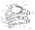
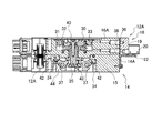
図1に示す自動工具交換装置10は、機器の本体である産業用ロボットのアームの先端(図示しない)に固定される第1連結部材12Aと、工具(図示しない)に固定される第2連結部材14とを備える。本図に示す第2連結部材14は、第1連結部材12Aに連結されていない状態では、置台24に設置されている。第1連結部材12Aは、第1連結本体16Aに設けられた位置決めピン17を、第2連結部材14の第2連結本体15に形成された位置決め穴13に挿入することにより、第2連結部材14に対し正確に位置決めされる。工具は特に限定されないが、例えばスポット溶接ガンや、ロボットハンドなどが用いられる。第1連結部材12Aとロボットアーム、及び第2連結部材14と工具は、図示しない締結具、例えばボルトにより、着脱自在に締結される。ロボットアームと工具は、自動工具交換装置10を介して、連結されると共に、分離される。
1. 1. Overall configuration (automatic tool changer)
The
第1連結部材12Aには、自動工具交換用カップラー(以下、「カップラー」という)18が設けられている。カップラー18は、第1方向切換え弁20と第2方向切換え弁21とを有する。第2連結部材14には、第1方向切換え弁20に対応した位置に、第1ドグ22が設けられている。置台24には、第2方向切換え弁21に対応した位置に、第2ドグ26が設けられている。
The first connecting
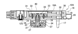
図2Aに示すように、第1連結部材12Aは、第1連結本体16Aと、第1連結本体16Aに設けられた、シリンダ30、コイルバネ32、及びカム34を有する。コイルバネ32は、シリンダ30を一方向に押し上げるように装填されている。シリンダ30は、一方向及び他方向(以下、軸方向という)に直線運動することにより、カム34を回転運動させる。
As shown in FIG. 2A, the first connecting
第1連結本体16Aは、略板状に形成された板状部25と、当該板状部25の表面から突出した突起部27と、板状部25内に形成されたシリンダ室31と、当該シリンダ室31の同軸上であって前記突起部27内に形成されたカム機構収容室28とが形成されている。シリンダ室31は、板状部25の他表面に形成された穴を、蓋40で閉塞することにより、形成される。シリンダ室31には、分離ポート36と連結ポート38が軸方向に並んで接続されている。板状部25の表面には、突起部27の周縁に第1接触面12Sが形成されている。
The first connecting
シリンダ30は、シリンダ室31内に配置されるピストン33と、ピストン33の中心軸に設けられたピストンロッド35と、ピストンロッド35の先端側に形成された操作部39とを有する。ピストン33は、シリンダ室31内を軸方向に摺動するように形成されている。分離ポート36と連結ポート38は、ピストン33を挟んでシリンダ室31の軸方向の一方側と、他方側に接続されている。ピストンロッド35は、基端がピストン33に連結されており、先端がカム機構収容室28に配置されている。ピストンロッド35の先端には、操作部39が設けられている。操作部39は、ピストンロッド35を半径方向に大きくした略円盤形状であり、軸方向に隙間を有する。
The
カム34は、逆L字型の部材であって、略中心において支持軸37を介して第1連結本体16Aの突起部27に回転自在に支持されており、一端側に付加部49、他端側に作用部55が形成されている。付加部49は、カム34の一端を挟んで一側に湾曲した凹面が形成されており、他側に平坦面が形成されている。作用部55は円弧形状に形成されている。付加部49は、操作部39の隙間に挿入され、凹面が隙間の上部に、平坦面が隙間の下部に接触している。カム34は、ピストンロッド35の直線運動によって、操作部39が凹面を押し下げたり、操作部39が平坦面を押し上げたりすることにより、支持軸37を中心として回転する。カム34は、突起部27の円周上に複数、本実施形態の場合、3個、均等に設けられている。
The
図2Bに示すように、第2連結部材14は、第2連結本体15と、第2連結本体15に固定された係合部品42とを有する。第2連結本体15は、略板状に形成されており、厚さ方向に開口した連結穴44を有する。連結穴44は、カム34の位置に対応した円周方向の位置に、係合部品42が設置されている。
As shown in FIG. 2B, the second connecting
図3に示すように、第1連結本体16Aは、カップラー18を取り付ける取付部51が外周面に設けられている。取付部51は、分離ポート36、連結ポート38、及びネジ穴53が設けられている。分離ポート36及び連結ポート38は、シリンダ30の軸方向に平行に並んで設けられている。本図の場合、分離ポート36が上側、連結ポート38が下側に配置されている。
As shown in FIG. 3, the first connecting
(カップラー)
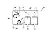
カップラー18は、図4に示すように、カップラー本体19を有し、当該カップラー本体19の一側表面に、第1方向切換え弁20と、第2方向切換え弁21とが設けられている。カップラー本体19は、一側表面に分離入力ポート41と連結入力ポート43が設けられ、他側表面に分離出力ポート45と連結出力ポート47が設けられており、内部に各ポートを連通する複数の流路(本図には図示しない)を有する。
(Coupler)
As shown in FIG. 4, the
分離入力ポート41及び連結入力ポート43には、図示しないが、コネクタを介して配管に接続される。配管はソレノイドバルブを介して圧縮機に接続されている。ソレノイドバルブは、分離入力ポート41への分離用気体又は連結入力ポート43への連結用気体の給気と、分離入力ポート41又は連結入力ポート43からの排気を切換える。分離入力ポート41と連結入力ポート43の中心間距離は、分離ポート36と連結ポート38の中心間距離以上に離れているのが好ましい。分離入力ポート41と連結入力ポート43の中心間距離が近すぎると、配管を分離入力ポート41と連結入力ポート43に接続する際の作業が困難になる。分離入力ポート41と連結入力ポート43の中心間距離は、分離ポート36と連結ポート38の中心間距離と略同じであるのがより好ましい。この場合、カップラー18を用いずに直接配管を分離ポート36と連結ポート38に接続する場合と同様の手順で配管を分離入力ポート41と連結入力ポート43に接続することができるので、違和感なく作業をすることができる。略同じとは、完全に同一である場合に限られず、カップラー18を用いずに配管を分離ポート36と連結ポート38に直接接続する場合に比べ、オペレータに違和感を与えない範囲を含む。
Although not shown, the
分離出力ポート45と連結出力ポート47は、取付部51の分離ポート36と連結ポート38にそれぞれ対応する位置に設けられている。連結入力ポート43と連結出力ポート47は略同軸上に配置されている。略同軸上とは、完全な同軸上に限定されるものではなく、連結入力ポート43と連結出力ポート47の中心軸が連結入力ポート43の半径の長さ程度にずれている場合を含む。
The separated
分離出力ポート45は連結出力ポート47に対し、前記シリンダ室31の軸方向に略平行に配置されている。分離入力ポート41は、分離出力ポート45に対し中心が少なくとも直径の長さだけ半径方向にずれた位置に配置されている。本図の場合、分離入力ポート41は、分離出力ポート45に対し、左側にずれた位置に配置されている。
The separated
カップラー本体19は、横長矩形の板状部材であって、長手方向一側(本図の場合左側)に分離入力ポート41及び連結入力ポート43が配置されており、長手方向他側(本図の場合右側)に第1方向切換え弁20と第2方向切換え弁21が配置されている。カップラー本体19は、下端が、第1連結本体16Aの第1接触面12Sと同じ高さに配置される。分離入力ポート41は、分離出力ポート45に対し、第1方向切換え弁20及び第2方向切換え弁21から離れる方向(本図の場合左側)にずれた位置に設けられている。
The coupler
第1方向切換え弁20及び第2方向切換え弁21は、ポートを3個有するバルブであり、機械式、電磁式のいずれを用いることもできる。本実施形態の場合、第1方向切換え弁20及び第2方向切換え弁21は、機械式のバルブを用いる。第1方向切換え弁20は、第1バルブ48、第2方向切換え弁21は、第2バルブ50を有する。第1方向切換え弁20と第2方向切換え弁21は、第1バルブ48及び第2バルブ50が、カップラー本体19の下端より下方へ突出するように配置されている。
The first
第1方向切換え弁20は、第1連結部材12Aと第2連結部材14が連結状態にあるか否かにより、第1方向切換え弁20の出力を切換える。第1方向切換え弁20は、第1バルブ48が、第1ドグ22に接触したか否かによって、第1連結部材12Aと第2連結部材14が連結状態にあるか否かを検出する(図8)。
The first
第2方向切換え弁21は、第1連結部材12Aが置台24に載せられた第2連結部材14と連結状態にあるか否かにより、第2方向切換え弁21の出力を切換える。第2方向切換え弁21は、第2バルブ50が、第2ドグ26に接触したか否かによって、第1連結部材12Aが置台24に載せられた第2連結部材14と連結状態にあるか否かを検出する。
The second
カップラー18は、カップラー本体19の厚さ方向に貫通する貫通穴に挿入した取り付けネジ(図示しない)を、取付部51のネジ穴にねじ込むことにより、第1連結部材12Aに固定される。カップラー18が取付部51に固定されることにより、分離出力ポート45がガスケット(図示しない)を介して分離ポート36に、連結出力ポート47がガスケットを介して連結ポート38に接続される。ガスケットとしては、例えばOリングを用いることができる。
The
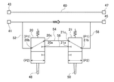
図5を参照して、カップラー18の内部に形成されている空気圧回路を説明する。第1方向切換え弁20と第2方向切換え弁21は、第1〜第3ポート20a〜20c、21a〜21cを有する。第1方向切換え弁20と第2方向切換え弁21は、スプリングによって、常時、第1位置P1に保持される。第1バルブ48は第1ドグ22によって、第2バルブ50は第2ドグ26によって、スプリングに対向して押された場合に、第1位置P1から第2位置P2にそれぞれ切換る。
The pneumatic circuit formed inside the
連結入力ポート43は、連結入力流路60を介して連結出力ポート47に接続されている。分離入力ポート41は、入力流路52を介して第1方向切換え弁20の第2ポート20bに接続されている。第1方向切換え弁20と第2方向切換え弁21は、第1ポート20a,21a同士が内部流路としての第1内部流路56を介して、第3ポート20c,21c同士が内部流路としての第2内部流路54を介して接続されている。第2方向切換え弁21の第2ポート21bは、出力流路58を介して分離出力ポート45に接続されている。
The
第1方向切換え弁20は、第1位置P1において、第2ポート20bと第3ポート20cとを接続する。第1バルブ48は、第2位置P2に切換ったとき、第2ポート20bと第1ポート20aを接続する。第2方向切換え弁21は、第1位置P1において、第3ポート21cと第2ポート21bとを接続する。第2バルブ50は、第2位置P2に切換ったとき、第1ポート21aと第2ポート21bとを接続する。
The first
2.動作及び効果
次に、第1連結部材12Aと第2連結部材14を連結する動作を説明する。まず、第1連結部材12Aと第2連結部材14を同軸上に配置し、位置決めする。この状態で給排気機構を通じて、ピストン33を挟んでシリンダ室31の一方側に、分離ポート36から流体として気体を供給する。この気体によってピストン33の一方側の圧力がコイルバネ32の力を上回ると、ピストン33が他方側へ移動、すなわち下降する。これにより操作部39がカム34の付加部49を押し下げる。そうするとカム34は、支持軸37を中心として矢印方向、すなわち図2中反時計回りに回転する。これによりカム34は、突起部27内に収容される(図6)。
2. Operation and Effect Next, an operation of connecting the first connecting
次いで、第1連結部材12Aの突起部27を第2連結部材14の連結穴44に、第1接触面12Sが第2接触面14Sに接触するまで挿入する。この状態で給排気機構を通じて、ピストン33を挟んでシリンダ室31の一方側の気体を分離ポート36から排出する。同時にピストン33を挟んでシリンダ室31の他方側へ連結ポート38から気体を供給する。この気体による圧力に、コイルバネ32の力が加わり、ピストン33は、他表面側へ移動、すなわち上昇する。これにより操作部39がカム34の付加部49を押し上げる。そうするとカム34は、支持軸37を中心として矢印方向、すなわち本図中時計回りに回転する。この回転によって、カム34は突起部27から放射状に突出し、作用部55が係合部品42の係合面と係合する。このようにして第1連結部材12Aと第2連結部材14が連結される(図7)。
Next, the
さらに、ピストン33を挟んでシリンダ室31の他方側へ連結ポート38から気体を排出する。同時にピストン33を挟んでシリンダ室31の一方側に、分離ポート36から気体を供給し、カム34を反時計回りに回転させ突起部27内に収容する。このようにして第1連結部材12Aと第2連結部材14を分離することができる。
Further, the gas is discharged from the connecting
本実施形態の自動工具交換装置10は、カップラー18を備えていることにより、第1連結部材12Aと第2連結部材14が分離している状態、第1連結部材12Aと第2連結部材14が連結されて作業中の状態、置台24に載せられた第2連結部材14に、第1連結部材12Aを挿入した状態において、以下のように動作する。
The
(分離状態)
第1連結部材12Aと第2連結部材14が分離している状態のとき、すなわち第1ドグ22及び第2ドグ26が第1位置P1にあるとき、分離入力ポート41は、第1方向切換え弁20及び第2方向切換え弁21を介して、分離出力ポート45に接続された状態となっている。したがって、図示しないソレノイドバルブを操作することにより、上記シリンダ30を連結方向及び分離方向に動作させることができる。
(Separated state)
When the first connecting
(ロボット作業中)
第1連結部材12Aと第2連結部材14が連結した状態で作業中のとき、第2連結部材14は置台24から離れているので、第1ドグ22が第2位置P2にあり、第2ドグ26が第1位置P1にある。このとき、第2方向切換え弁21が閉弁状態となり、分離入力ポート41は分離出力ポート45と切断されている。したがって、オペレータの誤操作や、電気ノイズなどにより、図示しないソレノイドバルブが動作したとしても、第1連結部材12Aから不用意に第2連結部材14が分離することを防止することができる。
(During robot work)
When working in a state where the first connecting
(第1連結部材12Aと、置台24に載せられた第2連結部材14の分離及び連結動作)
置台24に載せられた第2連結部材14に、第1連結部材12Aを挿入した状態のとき(図8)、すなわち第1ドグ22及び第2ドグ26が第2位置P2にあるとき、分離入力ポート41は、第1方向切換え弁20と第2方向切換え弁21を介して、分離出力ポート45に接続された状態となっている。したがって、図示しないソレノイドバルブを操作することにより、上記シリンダ30を連結方向及び分離方向に動作させることができる。
(Separation and connection operation of the first connecting
Separate input when the first connecting
本実施形態に係るカップラー本体19は、複数のポートを連通する複数の流路を有し、分離入力ポート41は、分離出力ポート45に対し中心が少なくとも直径の長さだけ半径方向にずれた位置に配置したことにより、分離ポート36と連結ポート38にロボット側の配管を直接接続できる。したがって、自動工具交換装置10は、カップラー18と、分離ポート36及び連結ポート38を繋ぐ配管を省略できるため、利便性をより向上することができる。中心を半径方向にずらした位置に配置したことにより、分離入力ポート41と分離出力ポート45の干渉が避けられ、カップラー本体19を小型化することができる。
The coupler
カップラー18は、長手方向左側に分離入力ポート41及び連結入力ポート43が配置され、長手方向右側に第1方向切換え弁20と第2方向切換え弁21が配置されており、分離入力ポート41を分離出力ポート45に対し左側にずれた位置に設けたので、全体として小型化を実現することができる。したがってカップラー18は、小型の自動工具交換装置10、すなわちシリンダ30の軸方向長さが小さい第1連結部材12Aに好適である。
In the
3.変形例
本発明は上記実施形態に限定されるものではなく、本発明の趣旨の範囲内で適宜変更することが可能である。
3. 3. Modifications The present invention is not limited to the above embodiment, and can be appropriately modified within the scope of the gist of the present invention.
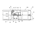
上記実施形態の場合、シリンダ30の軸方向長さが小さい第1連結部材12Aに適用する場合について説明したが、本発明はこれに限らない。例えば図9に示すように、カップラー18は、より大型の第1連結部材12Bに適用することもできる。当該カップラー18は、カップラー本体19の他側表面、すなわち取付部51側の表面に配置される第2カップラー本体61を備える。
In the case of the above embodiment, the case where the
図10に示すように、第1連結本体16Bは、分離ポート36と連結ポート38の間の間隔が、カップラー本体19の他側表面に形成された分離出力ポート45と連結出力ポート47の間隔より長い。第2カップラー本体61は、縦長矩形の板状部材であって、一側表面に第2分離入力ポート62と、第2連結入力ポート63とを有し、図示しないが他側表面に、第2分離出力ポートと、第2連結出力ポートとを有する。第2分離入力ポート62と、第2連結入力ポート63は、カップラー本体19の他側表面に形成された分離出力ポート45(図4)と、連結出力ポート47(図4)に対応した位置に形成されている。第2分離出力ポートと、第2連結出力ポートは、取付部51に形成された、分離ポート36と、連結ポート38に対応した位置に形成されている。また第2カップラー本体61は、図示しないが、内部に、第2分離入力ポート62と第2分離出力ポートとを繋ぐ分離流路と、第2連結入力ポート63と第2連結出力ポートとを繋ぐ連結流路とを有する。
As shown in FIG. 10, in the first connection
第2カップラー本体61を間に挟んでカップラー18を取付部51に固定することにより、分離出力ポート45は、第2分離入力ポート62、第2分離出力ポートを介して分離ポート36に接続される。同様に、連結出力ポート47は、第2連結入力ポート63、第2連結出力ポートを介して、連結ポート38に接続される。
By fixing the
上記変形例に係る第2カップラー本体61を用いることにより、カップラー本体19を、より大型の第1連結部材12Bに適用することができる。したがってカップラー18は、部品の共通化を図ることができ、汎用性を向上することができる。
By using the second coupler
上記実施形態の場合、自動工具交換装置10は、図2に示す断面構造を有する構成に適用した場合について説明したが、本発明はこれに限らず、第1連結部材12Aと第2連結部材14を分離又は連結する圧縮気体を導入する分離ポート36及び連結ポート38が、軸方向に平行に配置されているものであれば、他の構成の自動工具交換装置に適用することができる。
In the case of the above embodiment, the case where the automatic
上記実施形態の場合、分離入力ポート41を分離出力ポート45に対し左側にずれた位置に設けた場合について説明したが、本発明はこれに限られず、右側にずれた位置に設けてもよい。また分離入力ポート41は、分離出力ポート45に対し上側又は下側にずれた位置に設けてもよい。分離入力ポート41を分離出力ポート45に対し、上側又は下側にずれた位置に設けることにより、入力流路52と出力流路58の干渉も避けることができるので、カップラー本体をより薄型化することができる。さらに分離入力ポート41を分離出力ポート45に対し少なくとも直径の長さだけ左側であって、上下方向、すなわち分離出力ポート45に対し左斜め上方向の所定位置、又は左斜め下方向の所定位置に設けてもよい。上方向又は下方向の所定位置とは、入力流路52と出力流路58の干渉を避けることができる位置である。分離入力ポート41を分離出力ポート45に対し左斜め上方向又は下方向の所定位置に設けることにより、カップラー本体の縦と横の長さ、及び厚さを最適化できるので、カップラーをより小型化することができる。
In the case of the above embodiment, the case where the
10 自動工具交換装置
12A、12B 第1連結部材
14 第2連結部材
18 カップラー
19 カップラー本体
20 第1方向切換え弁
21 第2方向切換え弁
22 第1ドグ(ドグ)
24 置台
31 シリンダ室
34 カム
36 分離ポート
38 連結ポート
41 分離入力ポート
43 連結入力ポート
45 分離出力ポート
47 連結出力ポート
52 入力流路
54 第2内部流路(内部流路)
56 第1内部流路(内部流路)
58 出力流路
61 第2カップラー本体
62 第2分離入力ポート
63 第2連結入力ポート
10
24
56 First internal flow path (internal flow path)
58
Claims (4)
カップラー本体と、
前記カップラー本体の一側表面に設けられ、前記第1連結部材が前記第2連結部材と連結状態にあるか否かにより切換る第1方向切換え弁、及び、前記第1連結部材が置台に載せられた前記第2連結部材と連結状態にあるか否かにより切換る第2方向切換え弁と
を備え、
前記カップラー本体は、
複数のポートと、複数の前記ポートを連通する複数の流路と、
一側表面に、
連結用気体を導入する配管が接続される連結入力ポートと、
分離用気体を導入する配管が接続される分離入力ポートと、
前記一側表面に対向する他側表面に、
前記連結ポートに接続される連結出力ポートと、
前記分離ポートに接続される分離出力ポートと
を有し、
前記連結入力ポートと前記連結出力ポートは同軸上に配置され、
前記分離出力ポートは前記連結出力ポートに対し、前記シリンダ室の軸方向に平行に配置され、
前記分離入力ポートは、前記分離出力ポートに対し中心が少なくとも直径の長さだけ半径方向にずれた位置に配置されている
ことを特徴とする自動工具交換用カップラー。 A first connecting member detachably attached to the main body side of the device and a second connecting member detachably attached to the tool side are provided, and the first connecting member is connected to a cylinder chamber and the cylinder chamber. It has a connecting port and a separation port arranged parallel to the axial direction of the cylinder chamber, and the cam provided in the first connecting member is moved by supplying gas to the connecting port or the separation port to move the first connecting member. An automatic tool changing coupler used in an automatic tool changing device that connects or separates the second connecting member from one connecting member.
With the coupler body
A first-direction switching valve provided on one side surface of the coupler body and switching depending on whether or not the first connecting member is connected to the second connecting member, and the first connecting member are placed on a pedestal. It is provided with the second connecting member and a second direction switching valve that switches depending on whether or not it is in a connected state.
The coupler body
A plurality of ports, a plurality of channels communicating with the plurality of said ports, and a plurality of channels.
On one side surface,
The connection input port to which the piping for introducing the connection gas is connected, and
A separation input port to which a pipe for introducing a separation gas is connected,
On the other side surface facing the one side surface,
A concatenated output port connected to the concatenated port and
It has a separate output port connected to the separate port.
The concatenated input port and the concatenated output port are arranged coaxially.
The separated output port is arranged parallel to the connected output port in the axial direction of the cylinder chamber.
The separation input port is an automatic tool replacement coupler characterized in that the center is arranged at a position radially offset by at least the length of the diameter with respect to the separation output port.
前記分離入力ポートと前記第1方向切換え弁を繋ぐ入力流路と、
前記第1方向切換え弁と前記第2方向切換え弁を繋ぐ内部流路と、
前記第2方向切換え弁と前記分離出力ポートを繋ぐ出力流路と
を有することを特徴とする請求項1に記載の自動工具交換用カップラー。 The coupler body
An input flow path connecting the separation input port and the first direction switching valve,
An internal flow path connecting the first direction switching valve and the second direction switching valve,
The automatic tool replacement coupler according to claim 1, further comprising an output flow path connecting the second direction switching valve and the separation output port.
一側表面に、
前記連結出力ポートが接続される第2連結入力ポートと、
前記分離出力ポートが接続される第2分離入力ポートと、
前記一側表面に対向する他側表面に、
前記連結ポートに接続される第2連結出力ポートと、
前記分離ポートに接続される第2分離出力ポートと、
前記第2連結入力ポートと前記第2連結出力ポートとを繋ぐ連結流路と、
前記第2分離入力ポートと前記第2分離出力ポートとを繋ぐ分離流路と
を有することを特徴とする請求項1又は2に記載の自動工具交換用カップラー。 A second coupler body arranged on the other side surface of the coupler body is provided.
On one side surface,
The second concatenated input port to which the concatenated output port is connected and
The second separated input port to which the separated output port is connected and
On the other side surface facing the one side surface,
The second concatenated output port connected to the concatenated port and
The second separated output port connected to the separated port and
A connection flow path connecting the second connection input port and the second connection output port,
The automatic tool replacement coupler according to claim 1 or 2, further comprising a separation flow path connecting the second separation input port and the second separation output port.
前記第1方向切換え弁に対応する位置にドグが設けられた前記第2連結部材と
を備えたことを特徴とする自動工具交換装置。 The first connecting member provided with the automatic tool replacement coupler according to any one of claims 1 to 3.
An automatic tool changing device including the second connecting member provided with a dog at a position corresponding to the first direction switching valve.
Priority Applications (4)
| Application Number | Priority Date | Filing Date | Title |
|---|---|---|---|
| JP2017209591A JP6930895B2 (en) | 2017-10-30 | 2017-10-30 | Automatic tool changer coupler and automatic tool changer |
| CN201880065588.5A CN111246981B (en) | 2017-10-30 | 2018-10-19 | Automatic tool changing coupling and automatic tool changing device |
| US16/652,364 US11498171B2 (en) | 2017-10-30 | 2018-10-19 | Automatic tool exchange coupler and automatic tool exchange apparatus |
| PCT/JP2018/039014 WO2019087821A1 (en) | 2017-10-30 | 2018-10-19 | Automatic tool exchange coupler and automatic tool exchange apparatus |
Applications Claiming Priority (1)
| Application Number | Priority Date | Filing Date | Title |
|---|---|---|---|
| JP2017209591A JP6930895B2 (en) | 2017-10-30 | 2017-10-30 | Automatic tool changer coupler and automatic tool changer |
Publications (2)
| Publication Number | Publication Date |
|---|---|
| JP2019081212A JP2019081212A (en) | 2019-05-30 |
| JP6930895B2 true JP6930895B2 (en) | 2021-09-01 |
Family
ID=66331778
Family Applications (1)
| Application Number | Title | Priority Date | Filing Date |
|---|---|---|---|
| JP2017209591A Active JP6930895B2 (en) | 2017-10-30 | 2017-10-30 | Automatic tool changer coupler and automatic tool changer |
Country Status (4)
| Country | Link |
|---|---|
| US (1) | US11498171B2 (en) |
| JP (1) | JP6930895B2 (en) |
| CN (1) | CN111246981B (en) |
| WO (1) | WO2019087821A1 (en) |
Families Citing this family (3)
| Publication number | Priority date | Publication date | Assignee | Title |
|---|---|---|---|---|
| US11623354B2 (en) * | 2018-09-13 | 2023-04-11 | Kinova Inc. | Robotic arm with quick-connect clamping system and docking cradle |
| DE102020120525A1 (en) * | 2020-08-04 | 2022-02-10 | Ott-Jakob Spanntechnik Gmbh | Tool or workpiece holder |
| CN112873257B (en) * | 2021-01-13 | 2022-07-12 | 刘湘洪 | Industrial robot's tip work piece quick replacement device |
Family Cites Families (30)
| Publication number | Priority date | Publication date | Assignee | Title |
|---|---|---|---|---|
| JPS564565B1 (en) | 1971-07-05 | 1981-01-30 | ||
| FR2542243B1 (en) * | 1983-03-11 | 1987-01-23 | Syspro | TOOL HOLDER FOR INDUSTRIAL ROBOT |
| US4664588A (en) | 1984-03-09 | 1987-05-12 | Applied Robotics Inc. | Apparatus and method for connecting and exchanging remote manipulable elements to a central control source |
| EP0154227B1 (en) * | 1984-03-09 | 1989-11-02 | Applied Robotics, Inc. | Exchange system and method for connecting, and/or exchanging remote elements to a central control source |
| US4611377A (en) | 1984-06-04 | 1986-09-16 | Eoa Systems, Inc. | Interchangeable robot end-of-arm tooling system |
| US4676142A (en) * | 1984-06-04 | 1987-06-30 | Eoa Systems, Inc. | Adapter with modular components for a robot end-of-arm interchangeable tooling system |
| US4784421A (en) * | 1986-04-18 | 1988-11-15 | Mecanotron Corporation | Interchangeable tool mounting mechanism for robots |
| US4809747A (en) * | 1987-07-31 | 1989-03-07 | General Motors Corporation | Quick disconnect device |
| US4917619A (en) * | 1987-12-26 | 1990-04-17 | Obara Corporation | Tool changer for welding robot |
| US4990022A (en) * | 1988-03-07 | 1991-02-05 | Honda Giken Kogyo Kabushiki Kaisha | Robot hand coupling assembly |
| JPH0727101Y2 (en) * | 1990-11-28 | 1995-06-21 | エスエムシー株式会社 | Robot hand exchange device |
| JPH0742627Y2 (en) * | 1991-03-12 | 1995-10-04 | エスエムシー株式会社 | Hand exchange device for industrial robot |
| JP2881271B2 (en) * | 1991-12-24 | 1999-04-12 | ニッタ株式会社 | Automatic tool change coupler dropout prevention mechanism |
| JP3318677B2 (en) * | 1992-04-24 | 2002-08-26 | ニッタ株式会社 | Automatic tool changing coupler |
| JP3564565B2 (en) * | 1992-10-29 | 2004-09-15 | ニッタ株式会社 | Automatic tool change coupler |
| JP3312257B2 (en) * | 1993-01-26 | 2002-08-05 | ニッタ株式会社 | Automatic tool changer |
| JP3452646B2 (en) * | 1994-07-08 | 2003-09-29 | 株式会社コガネイ | Automatic hand changing equipment |
| DE29914930U1 (en) | 1999-08-26 | 1999-12-09 | Deckel Maho Gmbh | Machining unit of a machine tool |
| JP4186146B2 (en) * | 1999-10-18 | 2008-11-26 | Smc株式会社 | Robot hand tool mounting device |
| JP3689715B2 (en) * | 2001-10-11 | 2005-08-31 | ビー・エル・オートテック株式会社 | Robot arm coupling device |
| JP3619207B2 (en) * | 2002-04-24 | 2005-02-09 | 株式会社藤井合金製作所 | Piping connector |
| US6840895B2 (en) * | 2003-03-12 | 2005-01-11 | Ati Industrial Automation, Inc. | Tool side robotic safety interlock |
| JP5697549B2 (en) | 2011-06-03 | 2015-04-08 | ニッタ株式会社 | Automatic tool changer |
| DE202012009838U1 (en) * | 2012-07-24 | 2013-10-25 | Kinshofer Gmbh | Quick coupler |
| US9151343B2 (en) * | 2013-03-14 | 2015-10-06 | Ati Industrial Automation, Inc. | Ball lock compensator for use with a robotic device |
| US10661449B2 (en) * | 2014-08-20 | 2020-05-26 | Ati Industrial Automation, Inc. | Safe robotic tool changer |
| JP2016068202A (en) * | 2014-09-30 | 2016-05-09 | セイコーエプソン株式会社 | robot |
| JP6604531B2 (en) * | 2015-03-26 | 2019-11-13 | ニッタ株式会社 | Male member and tool changer |
| ITUB20160939A1 (en) | 2016-02-23 | 2017-08-23 | Gimatic S R L | Device for connecting pneumatic tools to a manipulator |
| US10780575B2 (en) * | 2017-06-22 | 2020-09-22 | Phd, Inc. | Robot end effector cuff |
-
2017
- 2017-10-30 JP JP2017209591A patent/JP6930895B2/en active Active
-
2018
- 2018-10-19 CN CN201880065588.5A patent/CN111246981B/en active Active
- 2018-10-19 WO PCT/JP2018/039014 patent/WO2019087821A1/en active Application Filing
- 2018-10-19 US US16/652,364 patent/US11498171B2/en active Active
Also Published As
| Publication number | Publication date |
|---|---|
| CN111246981A (en) | 2020-06-05 |
| CN111246981B (en) | 2022-10-04 |
| WO2019087821A1 (en) | 2019-05-09 |
| JP2019081212A (en) | 2019-05-30 |
| US11498171B2 (en) | 2022-11-15 |
| US20200269370A1 (en) | 2020-08-27 |
Similar Documents
| Publication | Publication Date | Title |
|---|---|---|
| JP6930895B2 (en) | Automatic tool changer coupler and automatic tool changer | |
| JP6791483B2 (en) | Tool changer | |
| CN107000217B (en) | Coupling member, female member, and tool exchange device | |
| CN106003117B (en) | Male member and tool changer | |
| US11167428B2 (en) | Suction-type gripping device | |
| JP2008030178A (en) | Clamping device | |
| JP2009072891A (en) | Clamping device | |
| WO2016167169A1 (en) | Cylinder device | |
| CN109424762B (en) | Mounting structure of solenoid valve for actuator and valve with actuator | |
| JP5212830B2 (en) | Clamping device | |
| TWI787860B (en) | Screw supply jig, dual-arm robot using the screw supply jig, and screw supply method | |
| CN216731507U (en) | Vacuum suction jig | |
| JPH0825265A (en) | Automatic hand changer | |
| JP2009196080A (en) | One-finger gripper device | |
| JP6403072B2 (en) | Fluid pressure cylinder | |
| JP4997361B2 (en) | Vacuum valve | |
| JP4241344B2 (en) | Fluid pressure cylinder | |
| TWI672431B (en) | Cylinder device | |
| JP5514686B2 (en) | Robot hand | |
| JP6648996B2 (en) | Link type clamp device | |
| TW202233372A (en) | Chuck apparatus | |
| JP2023000719A (en) | Clamp device | |
| JP3110346U (en) | Refrigerant piping connector | |
| JP2008307657A (en) | Robot hand and robot having it | |
| JP2004306176A (en) | Workpiece holding device |
Legal Events
| Date | Code | Title | Description |
|---|---|---|---|
| A621 | Written request for application examination |
Free format text: JAPANESE INTERMEDIATE CODE: A621 Effective date: 20201007 |
|
| TRDD | Decision of grant or rejection written | ||
| A01 | Written decision to grant a patent or to grant a registration (utility model) |
Free format text: JAPANESE INTERMEDIATE CODE: A01 Effective date: 20210720 |
|
| A61 | First payment of annual fees (during grant procedure) |
Free format text: JAPANESE INTERMEDIATE CODE: A61 Effective date: 20210812 |
|
| R150 | Certificate of patent or registration of utility model |
Ref document number: 6930895 Country of ref document: JP Free format text: JAPANESE INTERMEDIATE CODE: R150 |