JP6929969B2 - Battery management system and method for optimizing the internal resistance of the battery - Google Patents
Battery management system and method for optimizing the internal resistance of the battery Download PDFInfo
- Publication number
- JP6929969B2 JP6929969B2 JP2019562302A JP2019562302A JP6929969B2 JP 6929969 B2 JP6929969 B2 JP 6929969B2 JP 2019562302 A JP2019562302 A JP 2019562302A JP 2019562302 A JP2019562302 A JP 2019562302A JP 6929969 B2 JP6929969 B2 JP 6929969B2
- Authority
- JP
- Japan
- Prior art keywords
- battery
- current
- voltage
- point
- charging
- Prior art date
- Legal status (The legal status is an assumption and is not a legal conclusion. Google has not performed a legal analysis and makes no representation as to the accuracy of the status listed.)
- Active
Links
Images


Classifications
-
- G—PHYSICS
- G01—MEASURING; TESTING
- G01R—MEASURING ELECTRIC VARIABLES; MEASURING MAGNETIC VARIABLES
- G01R19/00—Arrangements for measuring currents or voltages or for indicating presence or sign thereof
- G01R19/165—Indicating that current or voltage is either above or below a predetermined value or within or outside a predetermined range of values
- G01R19/16533—Indicating that current or voltage is either above or below a predetermined value or within or outside a predetermined range of values characterised by the application
- G01R19/16538—Indicating that current or voltage is either above or below a predetermined value or within or outside a predetermined range of values characterised by the application in AC or DC supplies
- G01R19/16542—Indicating that current or voltage is either above or below a predetermined value or within or outside a predetermined range of values characterised by the application in AC or DC supplies for batteries
-
- G—PHYSICS
- G01—MEASURING; TESTING
- G01R—MEASURING ELECTRIC VARIABLES; MEASURING MAGNETIC VARIABLES
- G01R31/00—Arrangements for testing electric properties; Arrangements for locating electric faults; Arrangements for electrical testing characterised by what is being tested not provided for elsewhere
- G01R31/36—Arrangements for testing, measuring or monitoring the electrical condition of accumulators or electric batteries, e.g. capacity or state of charge [SoC]
- G01R31/3644—Constructional arrangements
- G01R31/3648—Constructional arrangements comprising digital calculation means, e.g. for performing an algorithm
-
- G—PHYSICS
- G01—MEASURING; TESTING
- G01R—MEASURING ELECTRIC VARIABLES; MEASURING MAGNETIC VARIABLES
- G01R31/00—Arrangements for testing electric properties; Arrangements for locating electric faults; Arrangements for electrical testing characterised by what is being tested not provided for elsewhere
- G01R31/36—Arrangements for testing, measuring or monitoring the electrical condition of accumulators or electric batteries, e.g. capacity or state of charge [SoC]
- G01R31/389—Measuring internal impedance, internal conductance or related variables
-
- H—ELECTRICITY
- H01—ELECTRIC ELEMENTS
- H01M—PROCESSES OR MEANS, e.g. BATTERIES, FOR THE DIRECT CONVERSION OF CHEMICAL ENERGY INTO ELECTRICAL ENERGY
- H01M10/00—Secondary cells; Manufacture thereof
- H01M10/42—Methods or arrangements for servicing or maintenance of secondary cells or secondary half-cells
- H01M10/425—Structural combination with electronic components, e.g. electronic circuits integrated to the outside of the casing
-
- H—ELECTRICITY
- H01—ELECTRIC ELEMENTS
- H01M—PROCESSES OR MEANS, e.g. BATTERIES, FOR THE DIRECT CONVERSION OF CHEMICAL ENERGY INTO ELECTRICAL ENERGY
- H01M10/00—Secondary cells; Manufacture thereof
- H01M10/42—Methods or arrangements for servicing or maintenance of secondary cells or secondary half-cells
- H01M10/44—Methods for charging or discharging
- H01M10/443—Methods for charging or discharging in response to temperature
-
- H—ELECTRICITY
- H01—ELECTRIC ELEMENTS
- H01M—PROCESSES OR MEANS, e.g. BATTERIES, FOR THE DIRECT CONVERSION OF CHEMICAL ENERGY INTO ELECTRICAL ENERGY
- H01M10/00—Secondary cells; Manufacture thereof
- H01M10/42—Methods or arrangements for servicing or maintenance of secondary cells or secondary half-cells
- H01M10/48—Accumulators combined with arrangements for measuring, testing or indicating the condition of cells, e.g. the level or density of the electrolyte
- H01M10/486—Accumulators combined with arrangements for measuring, testing or indicating the condition of cells, e.g. the level or density of the electrolyte for measuring temperature
-
- H—ELECTRICITY
- H02—GENERATION; CONVERSION OR DISTRIBUTION OF ELECTRIC POWER
- H02J—CIRCUIT ARRANGEMENTS OR SYSTEMS FOR SUPPLYING OR DISTRIBUTING ELECTRIC POWER; SYSTEMS FOR STORING ELECTRIC ENERGY
- H02J7/00—Circuit arrangements for charging or depolarising batteries or for supplying loads from batteries
- H02J7/0029—Circuit arrangements for charging or depolarising batteries or for supplying loads from batteries with safety or protection devices or circuits
- H02J7/00304—Overcurrent protection
-
- H—ELECTRICITY
- H02—GENERATION; CONVERSION OR DISTRIBUTION OF ELECTRIC POWER
- H02J—CIRCUIT ARRANGEMENTS OR SYSTEMS FOR SUPPLYING OR DISTRIBUTING ELECTRIC POWER; SYSTEMS FOR STORING ELECTRIC ENERGY
- H02J7/00—Circuit arrangements for charging or depolarising batteries or for supplying loads from batteries
- H02J7/0047—Circuit arrangements for charging or depolarising batteries or for supplying loads from batteries with monitoring or indicating devices or circuits
-
- H—ELECTRICITY
- H01—ELECTRIC ELEMENTS
- H01M—PROCESSES OR MEANS, e.g. BATTERIES, FOR THE DIRECT CONVERSION OF CHEMICAL ENERGY INTO ELECTRICAL ENERGY
- H01M10/00—Secondary cells; Manufacture thereof
- H01M10/42—Methods or arrangements for servicing or maintenance of secondary cells or secondary half-cells
- H01M10/425—Structural combination with electronic components, e.g. electronic circuits integrated to the outside of the casing
- H01M2010/4271—Battery management systems including electronic circuits, e.g. control of current or voltage to keep battery in healthy state, cell balancing
-
- H—ELECTRICITY
- H01—ELECTRIC ELEMENTS
- H01M—PROCESSES OR MEANS, e.g. BATTERIES, FOR THE DIRECT CONVERSION OF CHEMICAL ENERGY INTO ELECTRICAL ENERGY
- H01M10/00—Secondary cells; Manufacture thereof
- H01M10/42—Methods or arrangements for servicing or maintenance of secondary cells or secondary half-cells
- H01M10/425—Structural combination with electronic components, e.g. electronic circuits integrated to the outside of the casing
- H01M2010/4278—Systems for data transfer from batteries, e.g. transfer of battery parameters to a controller, data transferred between battery controller and main controller
-
- Y—GENERAL TAGGING OF NEW TECHNOLOGICAL DEVELOPMENTS; GENERAL TAGGING OF CROSS-SECTIONAL TECHNOLOGIES SPANNING OVER SEVERAL SECTIONS OF THE IPC; TECHNICAL SUBJECTS COVERED BY FORMER USPC CROSS-REFERENCE ART COLLECTIONS [XRACs] AND DIGESTS
- Y02—TECHNOLOGIES OR APPLICATIONS FOR MITIGATION OR ADAPTATION AGAINST CLIMATE CHANGE
- Y02E—REDUCTION OF GREENHOUSE GAS [GHG] EMISSIONS, RELATED TO ENERGY GENERATION, TRANSMISSION OR DISTRIBUTION
- Y02E60/00—Enabling technologies; Technologies with a potential or indirect contribution to GHG emissions mitigation
- Y02E60/10—Energy storage using batteries
Description
本発明は、バッテリーの充電時にバッテリーの内部抵抗を最適化するためのバッテリー管理システム及び方法に関する。 The present invention relates to a battery management system and method for optimizing the internal resistance of a battery when charging the battery.
本出願は、2018年1月3日出願の韓国特許出願第10−2018−0000878号に基づく優先権を主張し、該当出願の明細書及び図面に開示された内容は、すべて本出願に組み込まれる。 This application claims priority based on Korean Patent Application No. 10-2018-0000878 filed on January 3, 2018, and all the contents disclosed in the specification and drawings of the relevant application are incorporated into this application. ..
近年、ノートパソコン、ビデオカメラ、携帯電話などのような携帯用電子製品の需要が急増し、電気自動車、エネルギー貯蔵用蓄電池、ロボット、衛星などの開発が本格化するにつれて、繰り返して充放電可能な高性能バッテリーに対する研究が活発に行われている。 In recent years, the demand for portable electronic products such as laptop computers, video cameras, and mobile phones has increased rapidly, and as the development of electric vehicles, storage batteries for energy storage, robots, satellites, etc. has begun in earnest, it can be repeatedly charged and discharged. Active research is being conducted on high-performance batteries.
現在、ニッケルカドミウム電池、ニッケル水素電池、ニッケル亜鉛電池、リチウムバッテリーなどの電池が商用化しているが、中でもリチウムバッテリーはニッケル系列のバッテリーに比べてメモリ効果が殆ど起きず充放電が自在であり、自己放電率が非常に低くてエネルギー密度が高いという長所から脚光を浴びている。 Currently, batteries such as nickel-cadmium batteries, nickel-hydrogen batteries, nickel-zinc batteries, and lithium batteries are commercially available. Among them, lithium batteries have almost no memory effect compared to nickel-series batteries and can be charged and discharged freely. It is in the limelight because of its extremely low self-discharge rate and high energy density.
バッテリーが過充電されると寿命が短縮するため、バッテリーを充電する間は、バッテリーの状態に応じてバッテリーの出力電力を適応的に調節する必要がある。バッテリーの出力電力を調節するためには、バッテリーの内部抵抗を決定する過程が先行しなければならない。そのため、特許文献1のような従来技術では、事前実験を通じて特定充電状態と特定温度におけるバッテリーの電圧−電流特性を示す電圧データ及び電流データを記録し、最小自乗法のようなデータフィッティングアルゴリズムを用いて前記電圧−電流特性を直線化することで、特定充電状態と特定温度に対応する内部抵抗を算出する。
Since the life of the battery is shortened when it is overcharged, it is necessary to adaptively adjust the output power of the battery according to the state of the battery while charging the battery. In order to adjust the output power of the battery, the process of determining the internal resistance of the battery must precede. Therefore, in the prior art as in
しかし、バッテリーの充電状態及び温度が一定した状況であっても、充電電流の大きさによってバッテリーの内部抵抗は変わり得る。したがって、特許文献1などに開示された技術ではバッテリーの過充電を効果的に防止し難い。
However, even if the state of charge and the temperature of the battery are constant, the internal resistance of the battery may change depending on the magnitude of the charging current. Therefore, it is difficult to effectively prevent overcharging of the battery with the technology disclosed in
本発明は、上記問題点に鑑みてなされたものであり、特定充電状態及び特定温度に対応する電圧−電流特性プロファイルによって定義されるバッテリーの内部抵抗をバッテリーの充電電流に基づいて最適化するバッテリー管理システム及び方法を提供することを目的とする。 The present invention has been made in view of the above problems, and is a battery that optimizes the internal resistance of a battery defined by a voltage-current characteristic profile corresponding to a specific charging state and a specific temperature based on the charging current of the battery. The purpose is to provide management systems and methods.
本発明の他の目的及び長所は、下記の説明によって理解でき、本発明の実施形態によってより明らかに分かるであろう。また、本発明の目的及び長所は、特許請求の範囲に示される手段及びその組合せによって実現することができる。 Other objects and advantages of the present invention will be understood by the following description and will be more apparent by the embodiments of the present invention. In addition, the objects and advantages of the present invention can be realized by means and combinations thereof shown in the claims.
上記の目的を達成するための本発明の多様な実施形態は次のようである。 Various embodiments of the present invention for achieving the above object are as follows.
本発明の一実施形態によるバッテリーの内部抵抗を最適化するためのバッテリー管理システムは、前記バッテリーの充電電流を測定するように構成された電流測定部と、複数の電圧−電流特性プロファイルを保存するように構成されたメモリと、前記電流測定部及び前記メモリに動作可能に結合され、前記バッテリーの充電状態及び温度に基づいて前記複数の電圧−電流特性プロファイルから基準プロファイルを決定するように構成される制御部であって、前記基準プロファイルが出発点、終了点及び前記出発点と前記終了点との間に位置する複数の中間点を含む、制御部とを含む。前記制御部は、前記出発点及び前記終了点に基づいて前記バッテリーの内部抵抗を決定する。前記制御部は、前記複数の中間点のうちいずれか一つを基準点として設定する。前記制御部は、前記基準点及び前記終了点に基づいて前記内部抵抗よりも小さい基準抵抗を決定する。前記制御部は、前記充電電流、前記内部抵抗、前記基準抵抗及び所定の充電上限電流に基づいて前記内部抵抗よりも大きい最適抵抗を決定する。 A battery management system for optimizing the internal resistance of a battery according to an embodiment of the present invention stores a current measuring unit configured to measure the charging current of the battery and a plurality of voltage-current characteristic profiles. The memory configured as described above is operably coupled to the current measuring unit and the memory, and is configured to determine a reference profile from the plurality of voltage-current characteristic profiles based on the charge state and temperature of the battery. The control unit includes a control unit, the reference profile including a starting point, an ending point, and a plurality of intermediate points located between the starting point and the ending point. The control unit determines the internal resistance of the battery based on the starting point and the ending point. The control unit sets any one of the plurality of intermediate points as a reference point. The control unit determines a reference resistance smaller than the internal resistance based on the reference point and the end point. The control unit determines an optimum resistance larger than the internal resistance based on the charging current, the internal resistance, the reference resistance, and a predetermined charging upper limit current.
前記制御部は、前記出発点の電圧と前記終了点の電圧との差を前記終了点の電流で除して前記内部抵抗を決定することができる。前記出発点の電圧は、前記バッテリーの充電状態及び温度に対応する前記バッテリーの開放電圧を示すものであり得る。 The control unit can determine the internal resistance by dividing the difference between the voltage at the starting point and the voltage at the ending point by the current at the ending point. The voltage at the starting point may indicate the open circuit voltage of the battery corresponding to the state of charge and temperature of the battery.
前記終了点の電流は、前記充電上限電流と同一であり得る。 The current at the end point can be the same as the charging upper limit current.
前記制御部は、前記基準点の電圧、前記基準点の電流、前記終了点の電圧及び前記終了点の電流に基づいて前記基準抵抗を決定することができる。 The control unit can determine the reference resistance based on the voltage at the reference point, the current at the reference point, the voltage at the end point, and the current at the end point.
前記制御部は、下記の数式1を用いて、前記基準抵抗を決定することができる。

前記制御部は、下記の数式2を用いて、前記最適抵抗を決定することができる。
前記制御部は、前記複数の中間点のうち前記終了点に最も近い中間点を前記基準点として決定することができる。 The control unit can determine the intermediate point closest to the end point among the plurality of intermediate points as the reference point.
本発明の他の実施形態によるバッテリーパックは、前記バッテリー管理システムを含む。 A battery pack according to another embodiment of the present invention includes the battery management system.
本発明のさらに他の実施形態によるバッテリーの内部抵抗を最適化するための方法は、前記バッテリーの充電状態及び温度に基づいて複数の電圧−電流特性プロファイルから基準プロファイルを決定する段階であって、前記基準プロファイルが出発点、終了点及び前記出発点と前記終了点との間に位置する複数の中間点を含む、段階と、前記出発点及び前記終了点に基づいて前記バッテリーの内部抵抗を決定する段階と、前記複数の中間点のうちいずれか一つを基準点として設定する段階と、前記基準点及び前記終了点に基づいて前記内部抵抗よりも小さい基準抵抗を決定する段階と、前記バッテリーの充電電流、前記内部抵抗、前記基準抵抗及び所定の充電上限電流に基づいて前記内部抵抗よりも大きい最適抵抗を決定する段階とを含む。 A method for optimizing the internal resistance of a battery according to still another embodiment of the present invention is a step of determining a reference profile from a plurality of voltage-current characteristic profiles based on the state of charge and temperature of the battery. The internal resistance of the battery is determined based on the stage and the starting point and the ending point, wherein the reference profile includes a starting point, an ending point and a plurality of intermediate points located between the starting point and the ending point. Steps, a step of setting any one of the plurality of intermediate points as a reference point, a step of determining a reference resistance smaller than the internal resistance based on the reference point and the end point, and the battery. It includes a step of determining an optimum resistance larger than the internal resistance based on the charging current, the internal resistance, the reference resistance, and a predetermined charging upper limit current.
本発明の実施形態のうち少なくとも一つによれば、特定充電状態及び特定温度に対応する電圧−電流特性プロファイルによって定義されるバッテリーの内部抵抗をバッテリーの充電電流に基づいて最適化することができる。 According to at least one of the embodiments of the present invention, the internal resistance of the battery defined by the voltage-current characteristic profile corresponding to the specific charging state and the specific temperature can be optimized based on the charging current of the battery. ..
本発明の実施形態のうち少なくとも一つによれば、最適化された内部抵抗をバッテリーの出力電力の調節に用いることで、従来の技術よりバッテリーの過充電を効果的に防止することができる。 According to at least one of the embodiments of the present invention, by using the optimized internal resistance for adjusting the output power of the battery, it is possible to effectively prevent overcharging of the battery as compared with the conventional technique.
本発明の効果は、上述した効果に制限されることなく、その他の効果は特許請求の範囲の記載から当業者に明確に理解されるであろう。 The effects of the present invention are not limited to the effects described above, and other effects will be clearly understood by those skilled in the art from the description of the claims.
本明細書に添付される次の図面は、本発明の望ましい実施形態を例示するものであり、発明の詳細な説明とともに本発明の技術的な思想をさらに理解させる役割をするため、本発明は図面に記載された事項だけに限定されて解釈されてはならない。 The following drawings, which are attached to the present specification, exemplify a desirable embodiment of the present invention, and serve to further understand the technical idea of the present invention together with a detailed description of the present invention. It should not be construed as being limited to the matters described in the drawings.
以下、添付された図面を参照して本発明の望ましい実施形態を詳しく説明する。これに先立ち、本明細書及び請求範囲に使われた用語や単語は通常的や辞書的な意味に限定して解釈されてはならず、発明者自らは発明を最善の方法で説明するために用語の概念を適切に定義できるという原則に則して本発明の技術的な思想に応ずる意味及び概念で解釈されねばならない。 Hereinafter, preferred embodiments of the present invention will be described in detail with reference to the accompanying drawings. Prior to this, the terms and words used herein and in the scope of the claims should not be construed in a general or lexicographical sense, and the inventor himself should explain the invention in the best possible way. It must be interpreted in the meaning and concept corresponding to the technical idea of the present invention in accordance with the principle that the concept of the term can be properly defined.
したがって、本明細書に記載された実施形態及び図面に示された構成は、本発明のもっとも望ましい一実施形態に過ぎず、本発明の技術的な思想のすべてを代弁するものではないため、本出願の時点においてこれらに代替できる多様な均等物及び変形例があり得ることを理解せねばならない。 Therefore, the embodiments described herein and the configurations shown in the drawings are merely one of the most desirable embodiments of the present invention and do not represent all of the technical ideas of the present invention. It must be understood that at the time of filing, there may be a variety of equivalents and variants that can replace them.
また、本発明の説明において、関連公知構成または機能についての具体的な説明が本発明の要旨を不明瞭にし得ると判断される場合、その詳細な説明は省略する。 Further, in the description of the present invention, if it is determined that a specific description of the related known configuration or function can obscure the gist of the present invention, the detailed description thereof will be omitted.
第1、第2などのように序数を含む用語は、多様な構成要素のうちある一つをその他の要素と区別するために使われたものであり、これら用語によって構成要素が限定されることはない。 Terms that include ordinal numbers, such as first, second, etc., are used to distinguish one of the various components from the other, and these terms limit the components. There is no.
明細書の全体において、ある部分がある構成要素を「含む」とするとき、これは特に言及されない限り、他の構成要素を除外するものではなく、他の構成要素をさらに含み得ることを意味する。また、明細書に記載された「制御ユニット」のような用語は少なくとも一つの機能や動作を処理する単位を意味し、ハードウェア、ソフトウェア、またはハードウェアとソフトウェアとの組合せで具現され得る。 In the whole specification, when a part "contains" a component, this does not exclude other components unless otherwise specified, and means that other components may be further included. .. Also, terms such as "control unit" as described herein mean a unit that processes at least one function or operation and can be embodied in hardware, software, or a combination of hardware and software.
さらに、明細書の全体において、ある部分が他の部分と「連結」されるとするとき、これは「直接的な連結」だけではなく、他の素子を介在した「間接的な連結」も含む。 Further, in the whole specification, when one part is "connected" to another part, this includes not only "direct connection" but also "indirect connection" with other elements intervening. ..
図1は、本発明の一実施形態によるバッテリーパック1の機能的構成を示した図である。
FIG. 1 is a diagram showing a functional configuration of a
図1を参照すれば、バッテリーパック1は、バッテリー10、開閉器20及びバッテリー管理システム100を含む。前記開閉器20は、前記バッテリー管理システム100からのスイッチング信号(例えば、パルス幅変調信号)に答えて、前記バッテリー10の充電電流及び/または放電電流の大きさを調節するように構成される。以下、放電電流は正の値で測定され、充電電流は負の値で測定されると仮定する。
Referring to FIG. 1, the
前記バッテリー管理システム100は、前記バッテリー10に電気的に結合されて前記バッテリー10の状態をモニタリング及び制御するように構成される。前記バッテリー管理システム100は、センシング部110、メモリ120、制御部130及び通信インタフェース140を含む。
The
センシング部110は、電流測定部111を含む。電流測定部111は、所定の周期毎に前記バッテリー10を通じて流れる電流を測定し、測定された電流を示す電流信号を制御部130に伝送する。前記バッテリー10の放電時の電流を「放電電流」と称し、前記バッテリー10の充電時の電流を「充電電流」と称する。制御部130は、電流測定部111から伝送されたアナログ形態の電流信号をデジタル形態の電流データに変換することができる。
The
センシング部110は、電圧測定部112をさらに含むことができる。電圧測定部112は、所定の周期毎に前記バッテリー10の端子電圧を測定し、測定された端子電圧を示す電圧信号を制御部130に伝送する。制御部130は、電圧測定部112から伝送されたアナログ形態の電圧信号をデジタル形態の電圧データに変換することができる。
The
センシング部110は、温度測定部113をさらに含むことができる。温度測定部113は、所定の周期毎に前記バッテリー10の温度を測定し、測定された温度を示す温度信号を制御部130に伝送する。制御部130は、温度測定部113から伝送されたアナログ形態の温度信号をデジタル形態の温度データに変換することができる。電流測定部111、電圧測定部112及び温度測定部113は、互いに時間同期化されて動作し得る。
The
メモリ120は、複数の電圧−電流特性プロファイルを保存するように構成される。それぞれの電圧−電流特性プロファイルは、出発点、終了点及び複数の中間点を含む。出発点は、充電電流が0Aであるときに測定される開放電圧(OCV:open circuit voltage)を示す。終了点は、予め決められた充電上限電流と同じ定電流によるパルス充電時に測定された電圧を示す。それぞれの中間点は、0Aより大きく前記充電上限電流より小さい定電流で前記バッテリー10をパルス充電させたときに測定された前記バッテリー10の電圧を示す。
The
それぞれの電圧−電流特性プロファイルは、特定充電状態及び特定温度に関連付けられたものであり得る。例えば、複数の電圧−電流特性プロファイルのうちいずれか一つは、充電状態80%及び温度−20℃に関連し、他の一つは充電状態80%及び温度25℃に関連し得る。もちろん、他の充電状態及び温度に関連した多様な電圧−電流特性プロファイルがメモリ120に保存され得ることは当業者に自明である。
Each voltage-current characteristic profile can be associated with a particular charge state and a particular temperature. For example, any one of the plurality of voltage-current characteristic profiles may be associated with a charge state of 80% and a temperature of −20 ° C., and the other may be associated with a charge state of 80% and a temperature of 25 ° C. Of course, it will be obvious to those skilled in the art that various voltage-current characteristic profiles related to other charge states and temperatures can be stored in
メモリ120は、前記バッテリー管理システム100の全般的な動作に求められるデータ、命令語及びソフトウェアをさらに保存することができる。メモリ120は、フラッシュメモリ、ハードディスク、SSD(solid state disk)、SDD(silicon disk drive)、マルチメディアマイクロカード、RAM(random access memory)、SRAM(static RAM)、ROM(read only memory)、EEPROM(electrically erasable programmable ROM)、PROM(programmable ROM)のうち少なくとも一つの形態の保存媒体を含み得る。
The
制御部130は、センシング部110、メモリ120及び通信インタフェース140に動作可能に結合される。制御部130は、センシング部110から伝送された電流信号、電圧信号及び/または温度信号に基づいて前記バッテリー10の充電状態(SOC:state of charge)を推定することができる。制御部130は、アンペアカウンティングを用いて、電流信号に基づいて前記バッテリー10の充電状態を所定の周期毎に更新することができる。または、制御部130は、アンペアカウンティングの外に、拡張カルマンフィルタのような当業界で周知された公知の方法を用いて、前記バッテリー10の充電状態を所定の周期毎に更新することもできる。
The
制御部130は、センシング部110から伝送された温度信号に基づいて前記バッテリー10の温度を決定した後、推定された充電状態及び決定された温度に基づいて複数の電圧−電流特性プロファイルから基準プロファイルを決定することができる。基準プロファイルは、複数の電圧−電流特性プロファイルのうち推定された充電状態及び決定された温度に対応するいずれか一つの電圧−電流特性プロファイルであり得る。
The
制御部130は、ハードウェア的に、ASICs(application specific integrated circuits)、DSPs(digital signal processors)、DSPDs(digital signal processing devices)、PLDs(programmable logic devices)、FPGAs(field programmable gate arrays)、マイクロプロセッサ、その他の機能を実行するための電気的ユニットのうち少なくとも一つを用いて具現され得る。
In terms of hardware, the
通信インタフェース140は、電気自動車のECUのような外部装置2と通信可能に結合される。通信インタフェース140は、外部装置2からの命令メッセージを受信し、受信された命令メッセージを制御部130に提供することができる。前記命令メッセージは、前記装置の特定機能の活性化を求めるメッセージであり得る。通信インタフェース140は、制御部130からの通知メッセージを外部装置2に伝達することができる。前記通知メッセージは、制御部130によって実行された機能の結果を外部装置2に知らせるためのメッセージであり得る。
The
図2は本発明の他の実施形態によるバッテリー10の内部抵抗を最適化する方法を示したフロー図であり、図3は図2に示された方法の説明に参照される例示的な電圧−電流特性プロファイルを示したグラフである。
FIG. 2 is a flow chart showing a method of optimizing the internal resistance of the
図2を参照すれば、段階S200において、制御部130は、センシング部110を用いて前記バッテリー10の充電電流Ichr及び温度を測定する。
Referring to FIG. 2, in step S200, the
段階S210において、制御部130は、前記バッテリー10の充電状態(例えば、SOC80%)及び測定された温度(例えば、25℃)に基づいて、メモリ120に保存された複数の電圧−電流特性プロファイルから基準プロファイルを決定する。換言すれば、段階S210で決定される前記基準プロファイルは、前記複数の電圧−電流特性プロファイルのうち前記バッテリー10の充電状態(例えば、SOC80%)及び温度(例えば、25℃)に対応するいずれか一つの電圧−電流特性プロファイルである。前記基準プロファイルを決定するため、制御部130は段階S210の実行に先立って、センシング部110からの電流信号、電圧信号及び/または温度信号に基づいて前記バッテリー10の充電状態及び温度をそれぞれ最新の値に更新することができる。
In step S210, the
図3に示された電圧−電流特性プロファイル300は、段階S210によって決定された基準プロファイルを例示的に示したものであり、メモリ120に保存された複数の電圧−電流特性プロファイル300のうちSOC80%及び温度25℃に関連するものであり得る。
The voltage-current
電圧−電流特性プロファイル300は、合計5つの点、すなわち、出発点Pstart、複数の中間点Pinter_1、Pinter_2、Pinter_3及び終了点Pendを含むと仮定する。3つの中間点Pinter_1、Pinter_2、Pinter_3は、上述したように、出発点Pstartと終了点Pendとの間に位置する。
Voltage - current
電圧−電流特性プロファイル300は、前記バッテリー10と同じ電気化学的特性を有するように製作された他のバッテリーの充電状態及び温度がそれぞれが特定値に一定に維持される条件で、前記他のバッテリーを相異なる大きさの定電流Istart、Iinter_1、Iinter_2、Iinter_3、Iendで所定時間(例えば、10秒)繰り返してパルス充電させた時点で測定された前記他のバッテリーの端子電圧Vstart、Vinter_1、Vinter_2、Vinter_3、Vendによって定義することができる。例えば、Vinter_1は前記他のバッテリーの充電状態及び温度が80%及び温度25℃の条件で前記他のバッテリーをIinter_1で10秒間充電させたときに測定された電圧であり、Vinter_2は前記他のバッテリーの充電状態及び温度が80%及び温度25℃の条件で前記他のバッテリーをIinter_2で10秒間充電させたときに測定された電圧であり、Vinter_3は前記他のバッテリーの充電状態及び温度が80%及び温度25℃の条件で前記他のバッテリーをIinter_3で10秒間充電させたときに測定された電圧であり、Vendは前記他のバッテリーの充電状態及び温度が80%及び温度25℃の条件で前記他のバッテリーをIendで10秒間充電させたときに測定された電圧である。
The voltage-current
勿論、電圧−電流特性プロファイル300は、図3の図示と異なって、1つ又は2つの中間点のみを含むか、それとも、4つ以上の中間点を含んでも良い。
Of course, the voltage-current
電圧−電流特性プロファイル300を定義するそれぞれの点は、単一電圧と単一電流との対で表される。具体的に、出発点Pstart=(Vstart、Istart)、終了点Pend=(Vend、Iend)、中間点Pinter_1=(Vinter_1、Iinter_1)、中間点Pinter_2=(Vinter_2、Iinter_2)、中間点Pinter_3=(Vinter_3、Iinter_3)で表され得る。Vstartは充電電流がIstartのときに検出された電圧、Vinter_1は充電電流がIinter_1のときに検出された端子電圧、Vinter_2は充電電流がIinter_2のときに検出された端子電圧、Vinter_3は充電電流がIinter_3のときに検出された端子電圧、Vendは充電電流がIendのときに検出された端子電圧である。
Each point that defines the voltage-current
Vocv=Vstart<Vinter_1<Vinter_2<Vinter_3<Vendであり、Istart<Iinter_1<Iinter_2<Iinter_3<Iend=Imaxである。Vocvは、SOC80%及び温度25℃におけるバッテリー10の開放電圧を示す。Imaxは、前記充電上限電流を示し、過電流によるバッテリー10の損傷を防止するために与えられた値であり得る。Vendは、予め決められた充電上限電圧Vmaxと同一であり得る。制御部130は、充電上限電流Imaxを超過する電流がバッテリー10を通じて流れないように、バッテリー10の充電電流を制御することができる。
A V ocv = V start <V inter_1 <V inter_2 <V inter_3 <V end, a I start <I inter_1 <I inter_2 <I inter_3 <I end = I max. V ocv indicates the open circuit voltage of the
段階S220において、制御部130は、前記出発点Pstart及び前記終了点Pendに基づいて、バッテリー10の内部抵抗Rintを決定する。具体的に、前記出発点Pstartと前記終了点Pendとを通る直線は下記の数式3のように表すことができる。
前記内部抵抗Rintは、数式3のVとIに前記出発点Pstartと前記終了点Pendのそれぞれの電圧と電流を代入した連立方程式の解であって、制御部130は下記の数式4を用いて前記内部抵抗Rintを決定することができる。
段階S230において、制御部130は、基準プロファイル300から基準点Prefを決定する。前記基準点Prefは、前記電圧−電流特性プロファイル300に含まれた複数の中間点Pinter_1、Pinter_2、Pinter_3のうちいずれか一つである。k=1、2、3であるとき、制御部130は、下記の数式5を用いて中間点Pinter_kと終了点Pendとを通る直線の傾きGkを算出することができる。
制御部130は、算出された直線の傾きが最も小さくなる一つの中間点を前記基準点として設定することができる。例えば、図3の電圧−電流特性プロファイル300のように、G1>G2>G3の場合、制御部130はPinter_3を前記基準点Prefとして設定することができる。
The
代案的に、制御部130は、複数の中間点Pinter_1、Pinter_2、Pinter_3のうち終了点Pendと最も近い中間点Pinter_3を前記基準点Prefとして設定しても良い。
In alternative, the
段階S240において、制御部130は、基準点Pref及び終了点Pendに基づいて、前記内部抵抗Rintよりも小さい基準抵抗Rrefを決定する。
In step S240, the
具体的に、前記基準点Prefと前記終了点Pendとを通る直線は下記の数式6のように表すことができる。
数式6において、Vnewは、図3に示されたように、傾きがRrefと同一であって、前記基準点Prefを通る直線がV軸に交わる点の電圧である。 In Equation 6, V new is the voltage at the point where the slope is the same as R ref and the straight line passing through the reference point Pref intersects the V axis, as shown in FIG.
前記Vnew及び前記基準抵抗Rrefは、数式6のVとIに前記基準点Prefと前記終了点Pendのそれぞれの電圧と電流を代入した連立方程式の2つの解であって、制御部130は下記の数式7を用いて前記基準抵抗Rrefを決定することができる。
上述した例のように、前記基準点Prefが前記中間点Pinter_3である場合、数式7においてVref=Vinter_3であって、Iref=Iinter_3である。 As in the example described above, if the reference point P ref is the intermediate point P Inter_3, a V ref = V inter_3 In Equation 7, an I ref = I inter_3.
代案的に、前記基準抵抗Rrefは、前記電圧−電流特性プロファイル300のためにメモリ120に予め保存された値であり得、この場合、制御部130は、段階S230及びS240を実行する代わりに、前記基準抵抗Rrefをメモリ120から読み出すことができる。
Alternatively, the reference resistor R ref may be a value pre-stored in
図3を参照すれば、中間点Pinter_1、Pinter_2、Pinter_3は前記出発点Pstartと前記終了点Pendとを通る直線の上側に位置しているため、基準抵抗Rrefが内部抵抗Rintよりも小さいことを当業者であれば容易に理解することができる。 Referring to FIG. 3, the intermediate point P inter_1, P inter_2, since P Inter_3 is positioned above the straight line passing through the said end point P end The said starting point P start, the reference resistor R ref is the internal resistance R Those skilled in the art can easily understand that it is smaller than an int.
段階S250において、制御部130は、測定された前記充電電流Ichr、前記内部抵抗Rint、前記基準抵抗Rref及び前記充電上限電流Imaxに基づいて、最適抵抗Roptを決定する。このとき、前記最適抵抗Roptは前記内部抵抗Rintよりも大きい。もし、段階S250によって決定された前記最適抵抗Roptが前記内部抵抗Rintと同じであるか又は小さい場合、制御部130は段階S200〜S250のうち少なくとも一つの実行中に誤謬が発生したと判断して、段階S210に戻ることもできる。
In step S250, the
数式3のVとIに前記終了点Pendの電圧Vendと電流Iendをそれぞれ代入すれば、下記の数式8のように表すことができる。
数式6のVとIに前記終了点Pendの電圧Vendと電流Iendをそれぞれ代入すれば、下記の数式9のように表すことができる。
数式9をVnewに対して整理すれば、下記の数式10のように表すことができる。
数式10のVendに数式8の右辺であるVocv+IendRintを代入すれば、下記の数式11のように表すことができる。
図3において、Pchrは前記基準点Prefと前記終了点Pendとを通る直線上に位置する充電点である。前記充電点Pchrの電流は前記充電電流Ichrである。したがって、前記充電点Pchrの電圧Vchrは、数式6から下記の数式12のように表すことができる。
数式12のVnewに数式11の右辺であるVocv+(Rint−Rref)Iendを代入すれば、下記の数式13のように表すことができる。
前記出発点Pstartと前記充電点Pchrとを通る直線は下記の数式14のように表すことができる。
前記最適抵抗Roptは、前記出発点Pstartと前記充電点Pchrとを通る直線の傾きを示す。数式14のVとIに前記充電点Pchrの電圧Vchrと電流Ichrを代入すれば、数式15のように表すことができる。
数式15のVchrに数式13の右辺であるVocv+(Rint−Rref)Iend+RrefIchrを代入すれば、下記の数式16のように表すことができる。
制御部130は、数式16を用いて前記最適抵抗Roptを決定することができる。すなわち、制御部130は、段階S210〜段階S240を通じて得られたRint、Rref、Ichr及びIendを数式16に代入することで、前記最適抵抗Roptを決定することができる。
The
上述したように、RintはRrefよりも大きいため、RoptがRintよりも大きい。したがって、Roptを用いて前記バッテリー10の充電時に出力電力を制御する場合、Rintを用いて前記バッテリー10の充電時に出力電力を制御する方式に比べて、前記バッテリー10の過充電を効果的に防止することができる。
As described above, since R int is larger than R ref , R opt is larger than R int. Therefore, when the output power is controlled when the
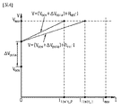
図4は、図2及び図3を参照して上述した前記内部抵抗に基づいて決定される充電制限電流と、前記最適抵抗に基づいて決定される充電制限電流との差を説明するために参照されるグラフである。 FIG. 4 is a reference for explaining the difference between the charge limiting current determined based on the internal resistance described above with reference to FIGS. 2 and 3 and the charge limit current determined based on the optimum resistance. It is a graph to be done.
図4を参照すれば、前記バッテリー10は、その使用状態によって、前記充電電流Ichrが測定された時点で分極電圧ΔVpolaが発生し得る。例えば、分極電圧ΔVpolaは、0Vより大きいものであり得る。制御部130は、最小自乗アルゴリズムなどのような公知のデータフィッティング法を用いて、前記バッテリー10の端子電圧に反映されている前記分極電圧ΔVpolaを決定することができる。
Referring to FIG. 4, the
前記分極電圧ΔVpolaが発生した場合、図3に示された前記電圧−電流特性プロファイル300は、図4のように、V軸に沿ってΔVpolaだけシフトして修正される。それによって、出発点PstartはPstart_polaにシフトし、終了点PendはPend_polaにシフトする。このとき、Pstart_pola=(VOCV+ΔVpola,0)であり、Pend_pola=(Vend+ΔVpola,Imax)である。図示していないが、図3の中間点Pinter_1、Pinter_2、Pinter_3もV軸に沿ってΔVpolaだけシフトする。
When the polarization voltage ΔV pola is generated, the voltage-current
前記分極電圧ΔVpolaを反映するため、数式3は下記の数式17に、数式14は下記の数式18にそれぞれ変更することができる。
In order to reflect the polarization voltage ΔV pola , the
前記バッテリー10の過充電を防止するためには、前記分極電圧ΔVpolaを考慮して前記バッテリー10のための充電制限電流を決定することが良い。
In order to prevent the
前記内部抵抗Rintに基づく充電制限電流Ilimit_1は、数式17に関連する下記の数式19を用いて決定することができる。
一方、制御部130は、数式18に関連する下記の数式20を用いて、前記最適抵抗Roptに基づく充電制限電流Ilimit_2を決定することができる。
RoptはRintよりも大きいため、Ilimit_2はIlimit_1よりも小さい。それによって、Ilimit_1の代わりにIlimit_2を前記バッテリー10の充電制限電流として決定する場合、前記バッテリー10の端子電圧の増加量が(Ilimit_1−Ilimit_2)に対応する大きさだけ減少するため、前記バッテリー10の過充電を効果的に防止することができる。
Since R opt is larger than R int , I limit _2 is smaller than I limit _1. As a result, when I limit_2 is determined as the charge limiting current of the
制御部130は、決定された充電制限電流Ilimit_2を超過する充電電流が流れないように、前記開閉器20に出力する前記スイッチング信号のデューティーサイクルを調節することができる。
The
上述した本発明の実施形態は、装置及び方法のみによって具現されるものではなく、本発明の実施形態の構成に対応する機能を実現するプログラムまたはそのプログラムが記録された記録媒体を通じても具現され得、このような具現は上述した実施形態の記載から当業者であれば容易に具現できるであろう。 The above-described embodiment of the present invention is not only embodied by an apparatus and a method, but can also be embodied through a program that realizes a function corresponding to the configuration of the embodiment of the present invention or a recording medium on which the program is recorded. , Such realization can be easily realized by those skilled in the art from the description of the above-described embodiment.
以上のように、本発明を限定された実施形態と図面によって説明したが、本発明はこれに限定されるものではなく、本発明の属する技術分野で通常の知識を持つ者によって本発明の技術思想と特許請求の範囲の均等範囲内で多様な修正及び変形が可能であることは言うまでもない。 As described above, the present invention has been described with reference to limited embodiments and drawings, but the present invention is not limited thereto, and the technique of the present invention is developed by a person having ordinary knowledge in the technical field to which the present invention belongs. It goes without saying that various modifications and modifications are possible within the same range of ideas and claims.
また、上述した本発明は、本発明が属する技術分野で通常の知識を持つ者により、本発明の技術的思想を逸脱しない範囲内で様々な置換、変形及び変更が可能であって、上述した実施形態及び添付の図面によって限定されるものではなく、多様な変形のため各実施形態の全部または一部が選択的に組み合わせられて構成され得る。 Further, the above-mentioned invention can be variously replaced, modified and changed by a person having ordinary knowledge in the technical field to which the present invention belongs, without departing from the technical idea of the present invention. Not limited by the embodiments and the accompanying drawings, all or part of each embodiment may be selectively combined and configured for various variations.
1:バッテリーパック
10:バッテリー
20:開閉器
100:バッテリー管理システム
110:センシング部
120:メモリ
130:制御部
140:通信インタフェース
1: Battery pack 10: Battery 20: Switch 100: Battery management system 110: Sensing unit 120: Memory 130: Control unit 140: Communication interface
Claims (5)
前記バッテリーの充電電流を測定するように構成された電流測定部と、
複数の電圧−電流特性プロファイルを保存するように構成されたメモリと、
前記電流測定部及び前記メモリに動作可能に結合され、前記バッテリーの充電状態及び温度に基づいて前記複数の電圧−電流特性プロファイルから基準プロファイルを決定するように構成される制御部であって、前記基準プロファイルが、充電電流が0Aであるときの前記バッテリーの開放電圧を示す出発点、予め決められた充電上限電流と同じ定電流によるパルス充電時に測定される前記バッテリーの電圧を示す終了点、及び前記出発点と前記終了点との間に位置する複数の中間点を含む、制御部とを含み、
前記複数の中間点のそれぞれは、0Aより大きく前記充電上限電流よりも小さい定電流によるパルス充電時に測定される前記バッテリーの電圧を示し、
前記制御部は、
前記出発点の電圧と前記終了点の電圧との差を前記終了点の電流で除して前記バッテリーの内部抵抗を決定し、
前記複数の中間点のうちいずれか一つを基準点として設定し、
前記基準点の電圧と前記終了点の電圧との差を、前記基準点の電流と前記終了点の電流との差で除して、前記内部抵抗よりも小さい基準抵抗を決定し、
下記の数式2を用いて、前記内部抵抗よりも大きい最適抵抗を決定する、バッテリー管理システム。
A current measuring unit configured to measure the charging current of the battery, and
With memory configured to store multiple voltage-current characteristic profiles,
A control unit that is operably coupled to the current measuring unit and the memory and is configured to determine a reference profile from the plurality of voltage-current characteristic profiles based on the state of charge and temperature of the battery. The reference profile is a starting point indicating the open circuit voltage of the battery when the charging current is 0A, an ending point indicating the voltage of the battery measured at the time of pulse charging with the same constant current as the predetermined charging upper limit current , and Includes a control unit that includes a plurality of intermediate points located between the start point and the end point.
Each of the plurality of intermediate points indicates the voltage of the battery measured at the time of pulse charging with a constant current larger than 0 A and smaller than the charge upper limit current.
The control unit
The difference between the voltage at the starting point and the voltage at the ending point is divided by the current at the ending point to determine the internal resistance of the battery.
One of the plurality of intermediate points is set as a reference point, and the reference point is set.
The difference between the voltage at the reference point and the voltage at the end point is divided by the difference between the current at the reference point and the current at the end point to determine a reference resistance smaller than the internal resistance.
A battery management system that uses Equation 2 below to determine an optimal resistance that is greater than the internal resistance.
前記バッテリーの充電状態及び温度に基づいて複数の電圧−電流特性プロファイルから基準プロファイルを決定する段階であって、前記基準プロファイルが、充電電流が0Aであるときの前記バッテリーの開放電圧を示す出発点、予め決められた充電上限電流と同じ定電流によるパルス充電時に測定される前記バッテリーの電圧を示す終了点、及び前記出発点と前記終了点との間に位置する複数の中間点を含み、前記複数の中間点のそれぞれは、0Aより大きく前記充電上限電流よりも小さい定電流によるパルス充電時に測定される前記バッテリーの電圧を示す、段階と、
前記出発点の電圧と前記終了点の電圧との差を前記終了点の電流で除して前記バッテリーの内部抵抗を決定する段階と、
前記複数の中間点のうちいずれか一つを基準点として設定する段階と、
前記基準点の電圧と前記終了点の電圧との差を、前記基準点の電流と前記終了点の電流との差で除して、前記内部抵抗よりも小さい基準抵抗を決定する段階と、
下記の数式2を用いて、前記内部抵抗よりも大きい最適抵抗を決定する段階とを含む、方法。
A step of determining a reference profile from a plurality of voltage-current characteristic profiles based on the charging state and temperature of the battery, where the reference profile indicates the open circuit voltage of the battery when the charging current is 0A. , end point indicating the voltage of the battery to be measured during pulse charging with the same constant current as the predetermined upper limit charging current, and saw including a plurality of intermediate points located between the end point and the starting point, Each of the plurality of midpoints indicates the voltage of the battery measured during pulse charging with a constant current greater than 0 A and less than the upper charge current .
A step of determining the internal resistance of the battery by dividing the difference between the voltage at the starting point and the voltage at the ending point by the current at the ending point.
At the stage of setting any one of the plurality of intermediate points as a reference point,
A step of dividing the difference between the voltage at the reference point and the voltage at the end point by the difference between the current at the reference point and the current at the end point to determine a reference resistance smaller than the internal resistance.
A method comprising the step of determining an optimum resistance greater than the internal resistance using Equation 2 below.
Applications Claiming Priority (3)
| Application Number | Priority Date | Filing Date | Title |
|---|---|---|---|
| KR10-2018-0000878 | 2018-01-03 | ||
| KR1020180000878A KR102255490B1 (en) | 2018-01-03 | 2018-01-03 | battery management system and method for optimizing an internal resistance of a battery |
| PCT/KR2018/014036 WO2019135487A1 (en) | 2018-01-03 | 2018-11-15 | Battery management system and method for optimizing internal resistance of battery |
Publications (2)
| Publication Number | Publication Date |
|---|---|
| JP2020520624A JP2020520624A (en) | 2020-07-09 |
| JP6929969B2 true JP6929969B2 (en) | 2021-09-01 |
Family
ID=67143730
Family Applications (1)
| Application Number | Title | Priority Date | Filing Date |
|---|---|---|---|
| JP2019562302A Active JP6929969B2 (en) | 2018-01-03 | 2018-11-15 | Battery management system and method for optimizing the internal resistance of the battery |
Country Status (9)
| Country | Link |
|---|---|
| US (1) | US11193982B2 (en) |
| EP (1) | EP3633782B1 (en) |
| JP (1) | JP6929969B2 (en) |
| KR (1) | KR102255490B1 (en) |
| CN (1) | CN110915056B (en) |
| ES (1) | ES2926853T3 (en) |
| HU (1) | HUE060046T2 (en) |
| PL (1) | PL3633782T3 (en) |
| WO (1) | WO2019135487A1 (en) |
Families Citing this family (2)
| Publication number | Priority date | Publication date | Assignee | Title |
|---|---|---|---|---|
| WO2021095895A1 (en) * | 2019-11-11 | 2021-05-20 | 엘지전자 주식회사 | Electronic device and charging control method of electronic device |
| CN115291123B (en) * | 2022-09-19 | 2023-03-07 | 伏达半导体(合肥)股份有限公司 | Method for characterizing a plurality of battery cells, battery parameter estimation device and method |
Family Cites Families (21)
| Publication number | Priority date | Publication date | Assignee | Title |
|---|---|---|---|---|
| JP3686776B2 (en) * | 1999-03-30 | 2005-08-24 | 日立バッテリー販売サービス株式会社 | Overdischarge prevention device for storage battery |
| US6522102B1 (en) * | 2001-12-14 | 2003-02-18 | Zinc Matrix Power, Inc. | Multiple plateau battery charging method and system to charge to the second plateau |
| JP4379283B2 (en) * | 2003-11-06 | 2009-12-09 | 東芝ライテック株式会社 | Charging circuit, emergency lighting device and lighting device |
| JP2006129588A (en) | 2004-10-28 | 2006-05-18 | Sanyo Electric Co Ltd | Power control method of secondary battery, and power unit |
| CN102129039B (en) | 2005-09-16 | 2013-01-16 | 古河电气工业株式会社 | Secondary cell degradation judgment method, secondary cell degradation judgment device, and power supply system |
| JP4930482B2 (en) | 2008-09-30 | 2012-05-16 | 株式会社デンソー | Battery charge / discharge control device |
| JP5393176B2 (en) * | 2009-01-26 | 2014-01-22 | カルソニックカンセイ株式会社 | Battery system and input / output power estimation method |
| JP5163542B2 (en) | 2009-03-03 | 2013-03-13 | 日産自動車株式会社 | Secondary battery input / output possible power estimation device |
| JP5682433B2 (en) | 2010-06-09 | 2015-03-11 | 日産自動車株式会社 | Charge control system |
| JP5558941B2 (en) | 2010-06-30 | 2014-07-23 | 三洋電機株式会社 | How to detect battery internal resistance |
| BR112013009715A2 (en) * | 2010-10-22 | 2016-07-19 | Nucleus Scient Inc | device and method to charge batteries quickly |
| KR101192010B1 (en) * | 2011-02-10 | 2012-10-16 | 삼성에스디아이 주식회사 | System for controlling charging of battery and battery pack comprising the same |
| US9182449B2 (en) * | 2012-10-12 | 2015-11-10 | GM Global Technology Operations LLC | Method and system for estimating battery capacity in a vehicle |
| KR101459449B1 (en) | 2013-04-15 | 2014-11-07 | 현대자동차 주식회사 | System and method for restarting voltage prediction of vehicle |
| JP5888315B2 (en) | 2013-12-18 | 2016-03-22 | トヨタ自動車株式会社 | Power storage system |
| KR101798201B1 (en) | 2014-10-01 | 2017-11-15 | 주식회사 엘지화학 | Method and Apparatus for estimating discharge power of secondary battery |
| DE102015001069A1 (en) * | 2015-01-29 | 2016-08-04 | Man Truck & Bus Ag | Method and device for temperature-dependent current limitation of an energy storage device for electrical energy |
| KR101846642B1 (en) * | 2015-02-02 | 2018-04-06 | 주식회사 엘지화학 | Method for determining resistance factor of secondary battery, and Apparatus and Method for estimating charging power of secondary battery using determined resistance factor |
| KR101783918B1 (en) * | 2015-02-24 | 2017-10-10 | 주식회사 엘지화학 | Apparatus and Method for Estimating Resistance of Secondary Battery |
| KR102364846B1 (en) | 2015-05-19 | 2022-02-18 | 삼성전자주식회사 | Battery pack and method of managing the battery pack |
| KR101874419B1 (en) | 2016-06-24 | 2018-07-04 | 주식회사 교원 | Air cleaning apparatus |
-
2018
- 2018-01-03 KR KR1020180000878A patent/KR102255490B1/en active IP Right Grant
- 2018-11-15 US US16/614,559 patent/US11193982B2/en active Active
- 2018-11-15 HU HUE18898336A patent/HUE060046T2/en unknown
- 2018-11-15 PL PL18898336.5T patent/PL3633782T3/en unknown
- 2018-11-15 WO PCT/KR2018/014036 patent/WO2019135487A1/en unknown
- 2018-11-15 CN CN201880035733.5A patent/CN110915056B/en active Active
- 2018-11-15 ES ES18898336T patent/ES2926853T3/en active Active
- 2018-11-15 EP EP18898336.5A patent/EP3633782B1/en active Active
- 2018-11-15 JP JP2019562302A patent/JP6929969B2/en active Active
Also Published As
| Publication number | Publication date |
|---|---|
| KR102255490B1 (en) | 2021-05-24 |
| US20200088805A1 (en) | 2020-03-19 |
| EP3633782A4 (en) | 2020-08-26 |
| PL3633782T3 (en) | 2022-10-31 |
| HUE060046T2 (en) | 2023-01-28 |
| CN110915056B (en) | 2023-04-07 |
| ES2926853T3 (en) | 2022-10-31 |
| KR20190083217A (en) | 2019-07-11 |
| US11193982B2 (en) | 2021-12-07 |
| EP3633782B1 (en) | 2022-08-10 |
| EP3633782A1 (en) | 2020-04-08 |
| CN110915056A (en) | 2020-03-24 |
| JP2020520624A (en) | 2020-07-09 |
| WO2019135487A1 (en) | 2019-07-11 |
Similar Documents
| Publication | Publication Date | Title |
|---|---|---|
| JP6884966B2 (en) | Battery management system and method for optimizing the internal resistance of the battery | |
| US9172261B2 (en) | Battery pack, method of charging secondary battery and battery charger | |
| US10873201B2 (en) | Battery management apparatus and method for protecting a lithium iron phosphate cell from over-voltage using the same | |
| US20210370796A1 (en) | Battery management apparatus, battery management method, battery pack, and electric vehicle | |
| JP2006129588A (en) | Power control method of secondary battery, and power unit | |
| EP3672021B1 (en) | Apparatus for preventing over-discharge | |
| US11824394B2 (en) | Battery management device, battery management method, and battery pack | |
| US11923710B2 (en) | Battery management apparatus, battery management method and battery pack | |
| KR20180044485A (en) | Effective battery cell-balancing method and system through the duty control | |
| US11567137B2 (en) | Battery management system, battery management method, battery pack and electric vehicle | |
| JP6929969B2 (en) | Battery management system and method for optimizing the internal resistance of the battery | |
| US11796599B2 (en) | Battery diagnosis apparatus, battery diagnosis method and energy storage system | |
| JP7062870B2 (en) | Battery management device, battery management method and battery pack | |
| JP2023538052A (en) | Battery management system, battery pack, electric vehicle and battery management method | |
| US20240079892A1 (en) | Battery management system, battery pack, electric vehicle, and battery management method | |
| CN112534283B (en) | Battery management system, battery management method, battery pack, and electric vehicle | |
| EP3872507B1 (en) | Battery management system, battery management method, battery pack, and electric vehicle | |
| KR20200042343A (en) | Apparatus and method for detecting battery temperature, and battery system including the apparatus |
Legal Events
| Date | Code | Title | Description |
|---|---|---|---|
| A621 | Written request for application examination |
Free format text: JAPANESE INTERMEDIATE CODE: A621 Effective date: 20191113 |
|
| A977 | Report on retrieval |
Free format text: JAPANESE INTERMEDIATE CODE: A971007 Effective date: 20201030 |
|
| A131 | Notification of reasons for refusal |
Free format text: JAPANESE INTERMEDIATE CODE: A131 Effective date: 20201104 |
|
| A521 | Request for written amendment filed |
Free format text: JAPANESE INTERMEDIATE CODE: A523 Effective date: 20210201 |
|
| TRDD | Decision of grant or rejection written | ||
| A01 | Written decision to grant a patent or to grant a registration (utility model) |
Free format text: JAPANESE INTERMEDIATE CODE: A01 Effective date: 20210713 |
|
| A61 | First payment of annual fees (during grant procedure) |
Free format text: JAPANESE INTERMEDIATE CODE: A61 Effective date: 20210811 |
|
| R150 | Certificate of patent or registration of utility model |
Ref document number: 6929969 Country of ref document: JP Free format text: JAPANESE INTERMEDIATE CODE: R150 |
|
| S111 | Request for change of ownership or part of ownership |
Free format text: JAPANESE INTERMEDIATE CODE: R313111 |
|
| R350 | Written notification of registration of transfer |
Free format text: JAPANESE INTERMEDIATE CODE: R350 |