EP3633782B1 - Battery management system and method for optimizing internal resistance of battery - Google Patents
Battery management system and method for optimizing internal resistance of battery Download PDFInfo
- Publication number
- EP3633782B1 EP3633782B1 EP18898336.5A EP18898336A EP3633782B1 EP 3633782 B1 EP3633782 B1 EP 3633782B1 EP 18898336 A EP18898336 A EP 18898336A EP 3633782 B1 EP3633782 B1 EP 3633782B1
- Authority
- EP
- European Patent Office
- Prior art keywords
- voltage
- current
- battery
- ref
- point
- Prior art date
- Legal status (The legal status is an assumption and is not a legal conclusion. Google has not performed a legal analysis and makes no representation as to the accuracy of the status listed.)
- Active
Links
- 238000000034 method Methods 0.000 title claims description 16
- 238000010278 pulse charging Methods 0.000 claims description 5
- 238000004891 communication Methods 0.000 description 7
- 238000007600 charging Methods 0.000 description 6
- 230000006870 function Effects 0.000 description 6
- 230000010287 polarization Effects 0.000 description 6
- 230000000694 effects Effects 0.000 description 3
- 238000005516 engineering process Methods 0.000 description 3
- 238000012986 modification Methods 0.000 description 3
- 230000004048 modification Effects 0.000 description 3
- WHXSMMKQMYFTQS-UHFFFAOYSA-N Lithium Chemical compound [Li] WHXSMMKQMYFTQS-UHFFFAOYSA-N 0.000 description 2
- PXHVJJICTQNCMI-UHFFFAOYSA-N Nickel Chemical compound [Ni] PXHVJJICTQNCMI-UHFFFAOYSA-N 0.000 description 2
- 238000010586 diagram Methods 0.000 description 2
- 229910052744 lithium Inorganic materials 0.000 description 2
- 238000012545 processing Methods 0.000 description 2
- XUIMIQQOPSSXEZ-UHFFFAOYSA-N Silicon Chemical compound [Si] XUIMIQQOPSSXEZ-UHFFFAOYSA-N 0.000 description 1
- 230000004913 activation Effects 0.000 description 1
- 238000003491 array Methods 0.000 description 1
- OJIJEKBXJYRIBZ-UHFFFAOYSA-N cadmium nickel Chemical compound [Ni].[Cd] OJIJEKBXJYRIBZ-UHFFFAOYSA-N 0.000 description 1
- 230000008859 change Effects 0.000 description 1
- 238000011161 development Methods 0.000 description 1
- 238000007599 discharging Methods 0.000 description 1
- 238000004146 energy storage Methods 0.000 description 1
- 238000002474 experimental method Methods 0.000 description 1
- 229910052739 hydrogen Inorganic materials 0.000 description 1
- 239000001257 hydrogen Substances 0.000 description 1
- 230000003446 memory effect Effects 0.000 description 1
- 229910052759 nickel Inorganic materials 0.000 description 1
- QELJHCBNGDEXLD-UHFFFAOYSA-N nickel zinc Chemical compound [Ni].[Zn] QELJHCBNGDEXLD-UHFFFAOYSA-N 0.000 description 1
- 230000001151 other effect Effects 0.000 description 1
- 230000008569 process Effects 0.000 description 1
- 230000004044 response Effects 0.000 description 1
- 229910052710 silicon Inorganic materials 0.000 description 1
- 239000010703 silicon Substances 0.000 description 1
- 239000007787 solid Substances 0.000 description 1
- 230000003068 static effect Effects 0.000 description 1
- 239000000126 substance Substances 0.000 description 1
- 238000006467 substitution reaction Methods 0.000 description 1
Images


Classifications
-
- G—PHYSICS
- G01—MEASURING; TESTING
- G01R—MEASURING ELECTRIC VARIABLES; MEASURING MAGNETIC VARIABLES
- G01R31/00—Arrangements for testing electric properties; Arrangements for locating electric faults; Arrangements for electrical testing characterised by what is being tested not provided for elsewhere
- G01R31/36—Arrangements for testing, measuring or monitoring the electrical condition of accumulators or electric batteries, e.g. capacity or state of charge [SoC]
- G01R31/389—Measuring internal impedance, internal conductance or related variables
-
- G—PHYSICS
- G01—MEASURING; TESTING
- G01R—MEASURING ELECTRIC VARIABLES; MEASURING MAGNETIC VARIABLES
- G01R19/00—Arrangements for measuring currents or voltages or for indicating presence or sign thereof
- G01R19/165—Indicating that current or voltage is either above or below a predetermined value or within or outside a predetermined range of values
- G01R19/16533—Indicating that current or voltage is either above or below a predetermined value or within or outside a predetermined range of values characterised by the application
- G01R19/16538—Indicating that current or voltage is either above or below a predetermined value or within or outside a predetermined range of values characterised by the application in AC or DC supplies
- G01R19/16542—Indicating that current or voltage is either above or below a predetermined value or within or outside a predetermined range of values characterised by the application in AC or DC supplies for batteries
-
- G—PHYSICS
- G01—MEASURING; TESTING
- G01R—MEASURING ELECTRIC VARIABLES; MEASURING MAGNETIC VARIABLES
- G01R31/00—Arrangements for testing electric properties; Arrangements for locating electric faults; Arrangements for electrical testing characterised by what is being tested not provided for elsewhere
- G01R31/36—Arrangements for testing, measuring or monitoring the electrical condition of accumulators or electric batteries, e.g. capacity or state of charge [SoC]
- G01R31/3644—Constructional arrangements
- G01R31/3648—Constructional arrangements comprising digital calculation means, e.g. for performing an algorithm
-
- H—ELECTRICITY
- H01—ELECTRIC ELEMENTS
- H01M—PROCESSES OR MEANS, e.g. BATTERIES, FOR THE DIRECT CONVERSION OF CHEMICAL ENERGY INTO ELECTRICAL ENERGY
- H01M10/00—Secondary cells; Manufacture thereof
- H01M10/42—Methods or arrangements for servicing or maintenance of secondary cells or secondary half-cells
- H01M10/425—Structural combination with electronic components, e.g. electronic circuits integrated to the outside of the casing
-
- H—ELECTRICITY
- H01—ELECTRIC ELEMENTS
- H01M—PROCESSES OR MEANS, e.g. BATTERIES, FOR THE DIRECT CONVERSION OF CHEMICAL ENERGY INTO ELECTRICAL ENERGY
- H01M10/00—Secondary cells; Manufacture thereof
- H01M10/42—Methods or arrangements for servicing or maintenance of secondary cells or secondary half-cells
- H01M10/44—Methods for charging or discharging
- H01M10/443—Methods for charging or discharging in response to temperature
-
- H—ELECTRICITY
- H01—ELECTRIC ELEMENTS
- H01M—PROCESSES OR MEANS, e.g. BATTERIES, FOR THE DIRECT CONVERSION OF CHEMICAL ENERGY INTO ELECTRICAL ENERGY
- H01M10/00—Secondary cells; Manufacture thereof
- H01M10/42—Methods or arrangements for servicing or maintenance of secondary cells or secondary half-cells
- H01M10/48—Accumulators combined with arrangements for measuring, testing or indicating the condition of cells, e.g. the level or density of the electrolyte
- H01M10/486—Accumulators combined with arrangements for measuring, testing or indicating the condition of cells, e.g. the level or density of the electrolyte for measuring temperature
-
- H—ELECTRICITY
- H02—GENERATION; CONVERSION OR DISTRIBUTION OF ELECTRIC POWER
- H02J—CIRCUIT ARRANGEMENTS OR SYSTEMS FOR SUPPLYING OR DISTRIBUTING ELECTRIC POWER; SYSTEMS FOR STORING ELECTRIC ENERGY
- H02J7/00—Circuit arrangements for charging or depolarising batteries or for supplying loads from batteries
- H02J7/0029—Circuit arrangements for charging or depolarising batteries or for supplying loads from batteries with safety or protection devices or circuits
- H02J7/00304—Overcurrent protection
-
- H—ELECTRICITY
- H02—GENERATION; CONVERSION OR DISTRIBUTION OF ELECTRIC POWER
- H02J—CIRCUIT ARRANGEMENTS OR SYSTEMS FOR SUPPLYING OR DISTRIBUTING ELECTRIC POWER; SYSTEMS FOR STORING ELECTRIC ENERGY
- H02J7/00—Circuit arrangements for charging or depolarising batteries or for supplying loads from batteries
- H02J7/0047—Circuit arrangements for charging or depolarising batteries or for supplying loads from batteries with monitoring or indicating devices or circuits
-
- H—ELECTRICITY
- H01—ELECTRIC ELEMENTS
- H01M—PROCESSES OR MEANS, e.g. BATTERIES, FOR THE DIRECT CONVERSION OF CHEMICAL ENERGY INTO ELECTRICAL ENERGY
- H01M10/00—Secondary cells; Manufacture thereof
- H01M10/42—Methods or arrangements for servicing or maintenance of secondary cells or secondary half-cells
- H01M10/425—Structural combination with electronic components, e.g. electronic circuits integrated to the outside of the casing
- H01M2010/4271—Battery management systems including electronic circuits, e.g. control of current or voltage to keep battery in healthy state, cell balancing
-
- H—ELECTRICITY
- H01—ELECTRIC ELEMENTS
- H01M—PROCESSES OR MEANS, e.g. BATTERIES, FOR THE DIRECT CONVERSION OF CHEMICAL ENERGY INTO ELECTRICAL ENERGY
- H01M10/00—Secondary cells; Manufacture thereof
- H01M10/42—Methods or arrangements for servicing or maintenance of secondary cells or secondary half-cells
- H01M10/425—Structural combination with electronic components, e.g. electronic circuits integrated to the outside of the casing
- H01M2010/4278—Systems for data transfer from batteries, e.g. transfer of battery parameters to a controller, data transferred between battery controller and main controller
-
- Y—GENERAL TAGGING OF NEW TECHNOLOGICAL DEVELOPMENTS; GENERAL TAGGING OF CROSS-SECTIONAL TECHNOLOGIES SPANNING OVER SEVERAL SECTIONS OF THE IPC; TECHNICAL SUBJECTS COVERED BY FORMER USPC CROSS-REFERENCE ART COLLECTIONS [XRACs] AND DIGESTS
- Y02—TECHNOLOGIES OR APPLICATIONS FOR MITIGATION OR ADAPTATION AGAINST CLIMATE CHANGE
- Y02E—REDUCTION OF GREENHOUSE GAS [GHG] EMISSIONS, RELATED TO ENERGY GENERATION, TRANSMISSION OR DISTRIBUTION
- Y02E60/00—Enabling technologies; Technologies with a potential or indirect contribution to GHG emissions mitigation
- Y02E60/10—Energy storage using batteries
Definitions
- the present disclosure relates to a battery management system and a method for optimizing an internal resistance of a battery when charging the battery.
- Patent Literature 1 records voltage data and current data indicating a voltage-current characteristic of the battery for a specific state of charge (SOC) and a specific temperature through experiments, and calculates the internal resistance corresponding to the specific SOC and the specific temperature by linearizing the voltage-current characteristic using a data fitting algorithm such as the least square method.
- SOC state of charge
- WO 2015/092986 A1 describes a method of determining the internal resistance of a battery.
- Patent Literature 1 is difficult to effectively prevent the overcharge of the battery.
- Patent Literature 1 Korean Patent Publication No. 10-2006-0052273 (published on May 19, 2006 )
- the present disclosure is designed to solve the above-described problem, and therefore the present disclosure is directed to a providing a battery management system and a method for optimizing the internal resistance of a battery defined by a voltage-current characteristic profile corresponding to a specific state of charge and a specific temperature according to the charge current of the battery.
- a battery management system for optimizing an internal resistance of a battery includes a current measuring unit configured to measure a charge current of the battery, a memory configured to store a plurality of voltage-current characteristic profiles, and a control unit operably coupled to the current measuring unit and the memory, and configured to determine a reference profile from the plurality of voltage-current characteristic profiles based on a state of charge and temperature of the battery, the reference profile including a start point, an end point, and a plurality of intermediate points disposed between the start point and the end point.
- the control unit determines the internal resistance of the battery based on the start point and the end point.
- the control unit sets one of the plurality of intermediate points as a reference point.
- the control unit determines a reference resistance that is lower than the internal resistance based on the reference point and the end point.
- the control unit determines an optimal resistance that is larger than the internal resistance based on the charge current, the internal resistance, the reference resistance and a predetermined upper limit of charge current.
- the control unit may determine the internal resistance by dividing a difference between a voltage of the start point and a voltage of the end point by a current of the end point.
- the voltage of the start point may indicate an open-circuit voltage of the battery corresponding to the state of charge and the temperature of the battery.
- the current of the end point may be equal to the upper limit of charge current.
- the control unit may determine the reference resistance based on the voltage of the reference point, the current of the reference point, the voltage of the end point and the current of the end point.
- Equation 1 I ref denotes the current of the reference point, V ref denotes the voltage of the reference point, I end denotes the current of the end point, V end denotes the voltage of the end point, and R ref denotes the reference resistance.
- Equation 2 R int denotes the internal resistance, I chr denotes the charge current, and R opt denotes the optimal resistance.
- the control unit may determine an intermediate point closest to the end point among the plurality of intermediate points as the reference point.
- a battery pack according to another embodiment of the present disclosure includes the battery management system.
- a method for optimizing an internal resistance of a battery includes determining a reference profile from a plurality of voltage-current characteristic profiles based on a state of charge and temperature of the battery, the reference profile including a start point, an end point, and a plurality of intermediate points disposed between the start point and the end point, determining the internal resistance of the battery based on the start point and the end point, setting one of the plurality of intermediate points as a reference point, determining a reference resistance that is lower than the internal resistance based on the reference point and the end point, and determining an optimal resistance that is larger than the internal resistance based on the charge current, the internal resistance, the reference resistance and a predetermined upper limit of charge current of the battery.
- the optimized internal resistance is used to adjust the output power of the battery, thereby preventing the overcharge of the battery more effectively than conventional technology.
- control unit> refers to a processing unit of at least one function or operation, and this may be implemented by hardware or software alone or in combination.
- FIG. 1 is a diagram showing the functional configuration of a battery pack 1 according to an embodiment of the present disclosure.
- the battery pack 1 includes a battery 10, a switch 20 and a battery management system 100.
- the switch 20 is configured to adjust the magnitude of the charge current and/or the discharge current of the battery 10 in response to a switching signal (e.g., a pulse width modulation signal) from the battery management system 100.
- a switching signal e.g., a pulse width modulation signal
- the battery management system 100 is electrically coupled to the battery 10 and configured to monitor and control the state of the battery 10.
- the battery management system 100 includes a sensing unit 110, a memory 120, a control unit 130 and a communication interface 140.
- the sensing unit 110 may include a current measuring unit 111.
- the current measuring unit 111 measures the current flowing through the battery 10 in a predetermined cycle, and transmits a current signal indicating the measured current to the control unit 130.
- the current during the discharge of the battery 10 may be referred to as 'discharge current', and the current during the charge of the battery 10 may be referred to as 'charge current'.
- the control unit 130 may convert the current signal in an analog form transmitted from the current measuring unit 111 to current data in a digital form.
- the sensing unit 110 may further include a voltage measuring unit 112.
- the voltage measuring unit 112 measures the terminal voltage of the battery 10 in a predetermined cycle, and transmits a voltage signal indicating the measured terminal voltage to the control unit 130.
- the control unit 130 may convert the voltage signal in an analog form transmitted from the voltage measuring unit 112 to voltage data in a digital form.
- the sensing unit 110 may further include a temperature measuring unit 113.
- the temperature measuring unit 113 measures the temperature of the battery 10 in a predetermined cycle, and transmits a temperature signal indicating the measured temperature to the control unit 130.
- the control unit 130 may convert the temperature signal in an analog form transmitted from the temperature measuring unit 113 to temperature data in a digital form.
- the current measuring unit 111, the voltage measuring unit 112 and the temperature measuring unit 113 may operate in time synchronization with each other.
- the memory 120 is configured to store a plurality of voltage-current characteristic profiles.
- Each voltage-current characteristic profile includes a start point, an end point and a plurality of intermediate points.
- the start point indicates an open-circuit voltage (OCV) measured when the charge current is 0A.
- the end point indicates voltage measured when pulse charging with a constant current that is equal to a preset upper limit of charge current.
- Each intermediate point indicates voltage of the battery 10 measured when pulse charging the battery 10 with a constant current that is larger than 0A and lower than the upper limit of charge current.
- Each voltage-current characteristic profile may be associated with a specific state of charge (SOC) and a specific temperature.
- SOC state of charge
- one of the plurality of voltage-current characteristic profiles may be associated with 80% SOC and temperature of -20°C, and the other may be associated with 80% SOC and temperature of 25°C.
- a variety of voltage-current characteristic profiles associated with other SOCs and temperatures may be stored in the memory 120.
- the memory 120 may additionally store data, instructions and software required for the entire operation of the battery management system 100.
- the memory 120 may include at least one type of storing medium of flash memory type, hard disk type, Solid State Disk (SSD) type, Silicon Disk Drive (SDD) type, multimedia card micro type, random access memory (RAM), static random access memory (SRAM), read-only memory (ROM), electrically erasable programmable read-only memory (EEPROM) and programmable read-only memory (PROM).
- the control unit 130 is operably coupled to the sensing unit 110, the memory 120 and the communication interface 140.
- the control unit 130 may estimate an SOC of the battery 10 based on the current signal, the voltage signal and/or the temperature signal transmitted from the sensing unit 110.
- the control unit 130 may update the SOC of the battery 10 in a predetermined cycle based on the current signal using ampere counting.
- the control unit 130 may update the SOC of the battery 10 in a predetermined cycle using a method widely known in the art other than ampere counting, such as the extended Kalman filter.
- the control unit 130 may determine the temperature of the battery 10 based on the temperature signal transmitted from the sensing unit 110, and determine a reference profile from the plurality of voltage-current characteristic profiles based on the estimated SOC and the determined temperature.
- the reference profile may be one of the plurality of voltage-current characteristic profiles corresponding to the estimated SOC and the determined temperature.
- the control unit 130 may be physically implemented using at least one of application specific integrated circuits (ASICs), digital signal processors (DSPs), digital signal processing devices (DSPDs), programmable logic devices (PLDs), field programmable gate arrays (FPGAs), microprocessors and electrical units for performing other functions.
- ASICs application specific integrated circuits
- DSPs digital signal processors
- DSPDs digital signal processing devices
- PLDs programmable logic devices
- FPGAs field programmable gate arrays
- microprocessors and electrical units for performing other functions.
- the communication interface 140 may be coupled to an external device 2 such as an ECU of an electric vehicle to enable communication therebetween.
- the communication interface 140 may receive a command message from the external device 2, and provide the received command message to the control unit 130.
- the command message may be a message that requires the activation of a specific function of the device.
- the communication interface 140 may transmit a notification message from the control unit 130 to the external device 2.
- the notification message may be a message for notifying the result of a function performed by the control unit 130 to the external device 2.
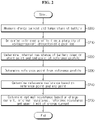
- FIG. 2 is a flowchart showing a method for optimizing the internal resistance of the battery 10 according to another embodiment of the present disclosure
- FIG. 3 is a graph showing an exemplary voltage-current characteristic profile for reference in describing the method of FIG. 2 .
- step S200 the control unit 130 measures the charge current I chr and temperature of the battery 10 using the sensing unit 110.
- step S210 the control unit 130 determines a reference profile from the plurality of voltage-current characteristic profiles stored in the memory 120 based on the SOC (e.g., 80% SOC) and the measured temperature (e.g., 25°C) of the battery 10.
- the reference profile determined through the step S210 is one of the plurality of voltage-current characteristic profiles corresponding to the SOC (e.g., 80% SOC) and temperature (e.g., 25°C) of the battery 10.
- the control unit 130 may update each of the SOC and temperature of the battery 10 to a latest value based on the current signal, the voltage signal and/or the temperature signal from the sensing unit 110 before performing the step S210.
- the voltage-current characteristic profile 300 shown in FIG. 3 exemplifies the reference profile determined by the step S210, and may be one associated with 80% SOC and temperature of 25°C among the plurality of voltage-current characteristic profiles 300 stored in the memory 120.
- the voltage-current characteristic profile 300 includes a total of five points, i.e., a start point P start , intermediate points P inter_1 , P inter_2 , P inter_3 and an end point P end .
- the three intermediate points P inter_1 , P inter_2 , P inter_3 are disposed between the start point P start and the end point P end as described above.
- the voltage-current characteristic profile 300 may be defined by the terminal voltage V start, V inter_1 , V inter_2 , V inter_3 , V end of the other battery measured at the time of pulse charging the other battery with different magnitudes of constant currents I start , I inter_1 , I inter_2 , I inter_3 , lend repeatedly for a predetermined time (e.g., 10sec).
- V inter_1 is voltage measured when charging the other battery with I inter_1 for 10 seconds in the condition in which the SOC and the temperature of the other battery are 80% and 25°C
- V inter_2 is voltage measured when charging the other battery with I inter_2 for 10 seconds in the condition in which the SOC and the temperature of the other battery are 80% and 25°C
- V inter_3 is voltage measured when charging the other battery with I inter_3 for 10 seconds in the condition in which the SOC and the temperature of the other battery are 80% and 25°C
- V end is voltage measured when charging the other battery with I end for 10 seconds in the condition in which the SOC and the temperature of the other battery are 80% and 25°C.
- the voltage-current characteristic profile 300 may include only one or two intermediate points or four or more intermediate points.
- Each point that defines the voltage-current characteristic profile 300 is expressed as a voltage-current pair.
- the start point P start (V start , I start )
- the end point Pend (Vend, lend)
- the intermediate point P inter_1 (V inter_1 , I inter_1 )
- the intermediate point P inter_2 (V inter_2 , I inter_2 )
- the intermediate point P inter_3 (V inter_3 , I inter_3 ).
- V start is the terminal voltage detected when the charge current is I start
- V inter_1 is the terminal voltage detected when the charge current is I inter_1
- V inter_2 is the terminal voltage detected when the charge current is I inter_2
- V inter_3 is the terminal voltage detected when the charge current is I inter_3
- V end is the terminal voltage detected when the charge current is lend.
- V ocv denotes the OCV of the battery 10 at SOC 80% and temperature of 25°C.
- I max denotes the upper limit of charge current, and may be a value given to prevent the battery 10 from being damaged by overcurrent.
- V end may be equal to a preset upper limit of charge voltage V max .
- the control unit 130 may control the charge current of the battery 10 to prevent the current exceeding the upper limit of charge current I max from flowing through the battery 10.
- step S220 the control unit 130 determines the internal resistance R int of the battery 10 based on the start point P start and the end point P end .
- a straight line passing through the start point P start and the end point P end may be represented by the following Equation 1.
- V V ocv + R int I
- the internal resistance R int is the solution of simultaneous equations obtained by substituting the voltage and current of each of the start point P start and the end point P end into V and I of Equation 1, and the control unit 130 may determine the internal resistance R int using the following Equation 2.
- R int V end ⁇ V start I end ⁇ I start
- the internal resistance R int may be a value pre-stored in the memory 120 for the voltage-current characteristic profile 300, and in this case, the control unit 130 may read the internal resistance R int from the memory 120 instead of performing the step S220.
- step S230 the control unit 130 determines a reference point P ref from the reference profile 300.
- the reference point P ref is one of the intermediate points P inter_1 , P inter_2 , P inter_3 included in the voltage-current characteristic profile 300.
- the control unit 130 may calculate the slope Gk of a straight line passing through the intermediate point P inter_k and the end point P end using the following Equation 3.
- G k V end ⁇ V inter _ k I end ⁇ I inter _ k
- the control unit 130 may set one intermediate point where the calculated slope of the straight line is smallest as the reference point. For example, when G 1 > G 2 > G 3 as shown in the voltage-current characteristic profile 300 of FIG. 3 , the control unit 130 may set P inter_3 as the reference point P ref .
- control unit 130 may set the intermediate point P inter_3 closest to the end point P end among the intermediate points P inter_1 , P inter_2 , P inter_3 as the reference point P ref .
- step S240 the control unit 130 determines a reference resistance R ref that is lower than the internal resistance R int based on the reference point P ref and the end point P end .
- V new is voltage of a point at which a straight line of the same slope as R ref passing through the reference point P ref meets the V axis as shown in FIG. 3 .
- V new and the reference resistance R ref are two solutions of the simultaneous equations obtained by substituting the voltage and current of each of the reference point P ref and the end point P end into V and I of Equation 4, and the control unit 130 may determine the reference resistance R ref using the following Equation 5.
- R ref V end ⁇ V ref I end ⁇ I ref
- V ref V inter_3
- I ref I inter_3 in Equation 5.
- the reference resistance R ref may be a value pre-stored in the memory 120 for the voltage-current characteristics profile 300, and in this case, the control unit 130 may read the reference resistance R ref from the memory 120 instead of performing the steps S230 and S240.
- step S250 the control unit 130 determines an optimal resistance R opt based on the measured charge current I chr , the internal resistance R int , the reference resistance R ref and the upper limit of charge current I max .
- the optimal resistance R opt is larger than the internal resistance R int .
- the control unit 130 may determine that an error occurred during the execution of at least one of the steps S200 ⁇ S250, and return to the step S210.
- V chr V new + R ref I chr
- the optimal resistance R opt indicates the slope of a straight passing through the start point P start and the charge point P chr .
- the control unit 130 may determine the optimal resistance R opt using Equation 14. That is, the control unit 130 may determine the optimal resistance R opt by substituting R int , R ref , I chr and lend obtained through the steps S210 to S240 into Equation 14.
- R int is larger than R ref
- R opt is larger than R int . Accordingly, controlling the output power using R opt during the charge of the battery 10 can prevent the overcharge of the battery 10 more effectively than controlling the output power using R int during the charge of the battery 10.
- FIG. 4 is a graph for reference in describing a difference between a limited charge current determined based on the internal resistance and a limited charge current determined based on the optimal resistance as described above with reference to FIGS. 2 and 3 .
- the battery 10 may have a polarization voltage ⁇ V pola at the time when the charge current I chr is measured according to the state of use of the battery 10.
- the polarization voltage ⁇ V pola may be larger than 0V.
- the control unit 130 may determine the polarization voltage ⁇ V pola reflected on the terminal voltage of the battery 10 using a known data fitting method such as the least square algorithm.
- the intermediate points P inter_1 , P inter_2 , P inter_3 of FIG. 3 are also shifted by ⁇ V pola along the V axis.
- Equation 1 may be changed to the following Equation 15, and Equation 12 may be changed to the following Equation 16.
- V V OCV + ⁇ V pola + R int I
- V V OCV + ⁇ V pola + R opt I
- the limited charge current I limit_1 based on the internal resistance R int may be determined using the following Equation 17 related to Equation 15.
- I limit _ 1 V max ⁇ V ocv + ⁇ V pola R int
- control unit 130 may determine a limited charge current I limit_2 based on the optimal resistance R opt using the following Equation 18 related to Equation 16.
- I limit _ 2 V max ⁇ V ocv + ⁇ V pola R opt
- L limit_2 is lower than I limit_1 . Accordingly, when instead of I limit_1 , L limit_2 is determined as the limited charge current of the battery 10, an increment amount of the terminal voltage of the battery 10 reduces by an amount corresponding to (I limit_1 - I limit_2 ), thereby effectively preventing the battery 10 from being overcharged.
- the control unit 130 may adjust the duty cycle of the switching signal outputted to the switch 20 to prevent the flow of the charge current exceeding the determined limited charge current L limit_2 .
Landscapes
- Engineering & Computer Science (AREA)
- Manufacturing & Machinery (AREA)
- Chemical & Material Sciences (AREA)
- Chemical Kinetics & Catalysis (AREA)
- Electrochemistry (AREA)
- General Chemical & Material Sciences (AREA)
- Physics & Mathematics (AREA)
- General Physics & Mathematics (AREA)
- Power Engineering (AREA)
- Microelectronics & Electronic Packaging (AREA)
- Secondary Cells (AREA)
- Charge And Discharge Circuits For Batteries Or The Like (AREA)
Description
- The present disclosure relates to a battery management system and a method for optimizing an internal resistance of a battery when charging the battery.
- The present application claims priority to
Korean Patent Application No. 10-2018-0000878 filed in the Republic of Korea on January 3, 2018 - Recently, there is dramatically growing demand for portable electronic products such as laptop computers, video cameras and mobile phones, and with the extensive development of electric vehicles, accumulators for energy storage, robots and satellites, many studies are being made on high performance batteries that can be recharged repeatedly.
- Currently, commercially available batteries include nickel-cadmium batteries, nickel-hydrogen batteries, nickel-zinc batteries, lithium batteries and the like, and among them, lithium batteries have little or no memory effect, and thus they are gaining more attention than nickel-based batteries for their advantages of free charging and discharging, a very low self-discharge rate and high energy density.
- Because a battery reduces in life when overcharged, it is necessary to adaptively adjust the output power of the battery according to the state of the battery during the charge of the battery. To adjust the output power of the battery, the process of determining the internal resistance of the battery is required. To this end, conventional technology such as
Patent Literature 1 records voltage data and current data indicating a voltage-current characteristic of the battery for a specific state of charge (SOC) and a specific temperature through experiments, and calculates the internal resistance corresponding to the specific SOC and the specific temperature by linearizing the voltage-current characteristic using a data fitting algorithm such as the least square method.WO 2015/092986 A1 describes a method of determining the internal resistance of a battery. - However, even in a situation in which the SOC and temperature of the battery is constant, the internal resistance of the battery may change depending on the magnitude of the charge current. Accordingly, the technology disclosed by
Patent Literature 1 is difficult to effectively prevent the overcharge of the battery. - (Patent Literature 1)
Korean Patent Publication No. 10-2006-0052273 (published on May 19, 2006 - The present disclosure is designed to solve the above-described problem, and therefore the present disclosure is directed to a providing a battery management system and a method for optimizing the internal resistance of a battery defined by a voltage-current characteristic profile corresponding to a specific state of charge and a specific temperature according to the charge current of the battery.
- These and other objects and advantages of the present disclosure will be understood by the following description and will be apparent from the embodiments of the present disclosure. Further, it will be readily understood that the objects and advantages of the present disclosure can be realized by the means set forth in the appended claims and combinations thereof.
- The invention is as defined in the appended claims. Various embodiments of the present disclosure for achieving the above-described object are as follows.
- A battery management system for optimizing an internal resistance of a battery according to an embodiment of the present disclosure includes a current measuring unit configured to measure a charge current of the battery, a memory configured to store a plurality of voltage-current characteristic profiles, and a control unit operably coupled to the current measuring unit and the memory, and configured to determine a reference profile from the plurality of voltage-current characteristic profiles based on a state of charge and temperature of the battery, the reference profile including a start point, an end point, and a plurality of intermediate points disposed between the start point and the end point. The control unit determines the internal resistance of the battery based on the start point and the end point. The control unit sets one of the plurality of intermediate points as a reference point. The control unit determines a reference resistance that is lower than the internal resistance based on the reference point and the end point. The control unit determines an optimal resistance that is larger than the internal resistance based on the charge current, the internal resistance, the reference resistance and a predetermined upper limit of charge current.
- The control unit may determine the internal resistance by dividing a difference between a voltage of the start point and a voltage of the end point by a current of the end point. The voltage of the start point may indicate an open-circuit voltage of the battery corresponding to the state of charge and the temperature of the battery.
- The current of the end point may be equal to the upper limit of charge current.
- The control unit may determine the reference resistance based on the voltage of the reference point, the current of the reference point, the voltage of the end point and the current of the end point.
- The control unit may determine the reference resistance using the following Equation 1:

- In
Equation 1, Iref denotes the current of the reference point, Vref denotes the voltage of the reference point, Iend denotes the current of the end point, Vend denotes the voltage of the end point, and Rref denotes the reference resistance. - The control unit may determine the optimal resistance using the following Equation 2:

- In
Equation 2, Rint denotes the internal resistance, Ichr denotes the charge current, and Ropt denotes the optimal resistance. - The control unit may determine an intermediate point closest to the end point among the plurality of intermediate points as the reference point.
- A battery pack according to another embodiment of the present disclosure includes the battery management system.
- A method for optimizing an internal resistance of a battery according to still another embodiment of the present disclosure includes determining a reference profile from a plurality of voltage-current characteristic profiles based on a state of charge and temperature of the battery, the reference profile including a start point, an end point, and a plurality of intermediate points disposed between the start point and the end point, determining the internal resistance of the battery based on the start point and the end point, setting one of the plurality of intermediate points as a reference point, determining a reference resistance that is lower than the internal resistance based on the reference point and the end point, and determining an optimal resistance that is larger than the internal resistance based on the charge current, the internal resistance, the reference resistance and a predetermined upper limit of charge current of the battery.
- According to at least one of the embodiments of the present disclosure, it is possible to optimize the internal resistance of a battery defined by a voltage-current characteristic profile corresponding to a specific state of charge and a specific temperature according to the charge current of the battery.
- According to at least one of the embodiments of the present disclosure, the optimized internal resistance is used to adjust the output power of the battery, thereby preventing the overcharge of the battery more effectively than conventional technology.
- The effects of the present disclosure are not limited to the above-mentioned effects, and other effects not mentioned herein will be clearly understood by those skilled in the art from the appended claims.
- The accompanying drawings illustrate a preferred embodiment of the present disclosure, and together with the following detailed description of the present disclosure, serve to provide a further understanding of the technical aspects of the present disclosure, and thus the present disclosure should not be construed as limited to the drawings.
-
FIG. 1 is a diagram showing the functional configuration of a battery pack according to an embodiment of the present disclosure. -
FIG. 2 is a flowchart showing a method for optimizing the internal resistance of a battery according to another embodiment of the present disclosure. -
FIG. 3 is a graph showing an exemplary voltage-current characteristic profile for reference in describing the method ofFIG. 2 . -
FIG. 4 is a graph for reference in describing a difference between a limited charge current determined based on the internal resistance and a limited charge current determined based on the optimal resistance as described above with reference toFIGS. 2 and3 . - Hereinafter, the preferred embodiments of the present disclosure will be described in detail with reference to the accompanying drawings. Prior to the description, it should be understood that the terms or words used in the specification and the appended claims should not be construed as being limited to general and dictionary meanings, but interpreted based on the meanings and concepts corresponding to the technical aspects of the present disclosure on the basis of the principle that the inventor is allowed to define the terms appropriately for the best explanation.
- Therefore, the embodiments described herein and illustrations shown in the drawings are just a most preferred embodiment of the present disclosure, but not intended to fully describe the technical aspects of the present disclosure, so it should be understood that a variety of other equivalents and modifications could be made thereto at the time of filing the application.
- Additionally, in describing the present disclosure, when it is deemed that a certain detailed description of relevant known elements or functions renders the key subject matter of the present disclosure ambiguous, the detailed description is omitted herein.
- The terms including the ordinal number such as "first", "second" and the like, may be used to distinguish one element from another among various elements, but not intended to limit the elements by the terms.
- Unless the context clearly indicates otherwise, it will be understood that the term "comprises" or "includes" when used in this specification, specifies the presence of stated elements, but does not preclude the presence or addition of one or more other elements. Additionally, the term <control unit> as used herein refers to a processing unit of at least one function or operation, and this may be implemented by hardware or software alone or in combination.
- In addition, throughout the specification, it will be further understood that when an element is referred to as being "connected to" another element, it can be directly connected to the other element or intervening elements may be present.
-
FIG. 1 is a diagram showing the functional configuration of abattery pack 1 according to an embodiment of the present disclosure. - Referring to
FIG. 1 , thebattery pack 1 includes abattery 10, aswitch 20 and abattery management system 100. Theswitch 20 is configured to adjust the magnitude of the charge current and/or the discharge current of thebattery 10 in response to a switching signal (e.g., a pulse width modulation signal) from thebattery management system 100. Hereinafter, assume that the discharge current is measured in a positive value, and the charge current is measured in a negative value. - The
battery management system 100 is electrically coupled to thebattery 10 and configured to monitor and control the state of thebattery 10. Thebattery management system 100 includes asensing unit 110, amemory 120, acontrol unit 130 and acommunication interface 140. - The
sensing unit 110 may include acurrent measuring unit 111. Thecurrent measuring unit 111 measures the current flowing through thebattery 10 in a predetermined cycle, and transmits a current signal indicating the measured current to thecontrol unit 130. The current during the discharge of thebattery 10 may be referred to as 'discharge current', and the current during the charge of thebattery 10 may be referred to as 'charge current'. Thecontrol unit 130 may convert the current signal in an analog form transmitted from thecurrent measuring unit 111 to current data in a digital form. - The
sensing unit 110 may further include avoltage measuring unit 112. Thevoltage measuring unit 112 measures the terminal voltage of thebattery 10 in a predetermined cycle, and transmits a voltage signal indicating the measured terminal voltage to thecontrol unit 130. Thecontrol unit 130 may convert the voltage signal in an analog form transmitted from thevoltage measuring unit 112 to voltage data in a digital form. - The
sensing unit 110 may further include a temperature measuring unit 113. The temperature measuring unit 113 measures the temperature of thebattery 10 in a predetermined cycle, and transmits a temperature signal indicating the measured temperature to thecontrol unit 130. Thecontrol unit 130 may convert the temperature signal in an analog form transmitted from the temperature measuring unit 113 to temperature data in a digital form. Thecurrent measuring unit 111, thevoltage measuring unit 112 and the temperature measuring unit 113 may operate in time synchronization with each other. - The
memory 120 is configured to store a plurality of voltage-current characteristic profiles. Each voltage-current characteristic profile includes a start point, an end point and a plurality of intermediate points. The start point indicates an open-circuit voltage (OCV) measured when the charge current is 0A. The end point indicates voltage measured when pulse charging with a constant current that is equal to a preset upper limit of charge current. Each intermediate point indicates voltage of thebattery 10 measured when pulse charging thebattery 10 with a constant current that is larger than 0A and lower than the upper limit of charge current. - Each voltage-current characteristic profile may be associated with a specific state of charge (SOC) and a specific temperature. For example, one of the plurality of voltage-current characteristic profiles may be associated with 80% SOC and temperature of -20°C, and the other may be associated with 80% SOC and temperature of 25°C. Of course, a variety of voltage-current characteristic profiles associated with other SOCs and temperatures may be stored in the
memory 120. - The
memory 120 may additionally store data, instructions and software required for the entire operation of thebattery management system 100. Thememory 120 may include at least one type of storing medium of flash memory type, hard disk type, Solid State Disk (SSD) type, Silicon Disk Drive (SDD) type, multimedia card micro type, random access memory (RAM), static random access memory (SRAM), read-only memory (ROM), electrically erasable programmable read-only memory (EEPROM) and programmable read-only memory (PROM). - The
control unit 130 is operably coupled to thesensing unit 110, thememory 120 and thecommunication interface 140. Thecontrol unit 130 may estimate an SOC of thebattery 10 based on the current signal, the voltage signal and/or the temperature signal transmitted from thesensing unit 110. Thecontrol unit 130 may update the SOC of thebattery 10 in a predetermined cycle based on the current signal using ampere counting. Alternatively, thecontrol unit 130 may update the SOC of thebattery 10 in a predetermined cycle using a method widely known in the art other than ampere counting, such as the extended Kalman filter. - The
control unit 130 may determine the temperature of thebattery 10 based on the temperature signal transmitted from thesensing unit 110, and determine a reference profile from the plurality of voltage-current characteristic profiles based on the estimated SOC and the determined temperature. The reference profile may be one of the plurality of voltage-current characteristic profiles corresponding to the estimated SOC and the determined temperature. - The
control unit 130 may be physically implemented using at least one of application specific integrated circuits (ASICs), digital signal processors (DSPs), digital signal processing devices (DSPDs), programmable logic devices (PLDs), field programmable gate arrays (FPGAs), microprocessors and electrical units for performing other functions. - The
communication interface 140 may be coupled to anexternal device 2 such as an ECU of an electric vehicle to enable communication therebetween. Thecommunication interface 140 may receive a command message from theexternal device 2, and provide the received command message to thecontrol unit 130. The command message may be a message that requires the activation of a specific function of the device. Thecommunication interface 140 may transmit a notification message from thecontrol unit 130 to theexternal device 2. The notification message may be a message for notifying the result of a function performed by thecontrol unit 130 to theexternal device 2. -
FIG. 2 is a flowchart showing a method for optimizing the internal resistance of thebattery 10 according to another embodiment of the present disclosure, andFIG. 3 is a graph showing an exemplary voltage-current characteristic profile for reference in describing the method ofFIG. 2 . - Referring to
FIG. 2 , in step S200, thecontrol unit 130 measures the charge current Ichr and temperature of thebattery 10 using thesensing unit 110. - In step S210, the
control unit 130 determines a reference profile from the plurality of voltage-current characteristic profiles stored in thememory 120 based on the SOC (e.g., 80% SOC) and the measured temperature (e.g., 25°C) of thebattery 10. In other words, the reference profile determined through the step S210 is one of the plurality of voltage-current characteristic profiles corresponding to the SOC (e.g., 80% SOC) and temperature (e.g., 25°C) of thebattery 10. To determine the reference profile, thecontrol unit 130 may update each of the SOC and temperature of thebattery 10 to a latest value based on the current signal, the voltage signal and/or the temperature signal from thesensing unit 110 before performing the step S210. - The voltage-current
characteristic profile 300 shown inFIG. 3 exemplifies the reference profile determined by the step S210, and may be one associated with 80% SOC and temperature of 25°C among the plurality of voltage-currentcharacteristic profiles 300 stored in thememory 120. - Assume that the voltage-current
characteristic profile 300 includes a total of five points, i.e., a start point Pstart, intermediate points Pinter_1, Pinter_2, Pinter_3 and an end point Pend. The three intermediate points Pinter_1, Pinter_2, Pinter_3 are disposed between the start point Pstart and the end point Pend as described above. - In the condition in which each of SOC and temperature of other battery fabricated with the same electrical and chemical properties as the
battery 10 is uniformly maintained at a specific value, the voltage-currentcharacteristic profile 300 may be defined by the terminal voltage Vstart, Vinter_1, Vinter_2, Vinter_3, Vend of the other battery measured at the time of pulse charging the other battery with different magnitudes of constant currents Istart, Iinter_1, Iinter_2, Iinter_3, lend repeatedly for a predetermined time (e.g., 10sec). For example, Vinter_1 is voltage measured when charging the other battery with Iinter_1 for 10 seconds in the condition in which the SOC and the temperature of the other battery are 80% and 25°C, Vinter_2 is voltage measured when charging the other battery with Iinter_2 for 10 seconds in the condition in which the SOC and the temperature of the other battery are 80% and 25°C, Vinter_3 is voltage measured when charging the other battery with Iinter_3 for 10 seconds in the condition in which the SOC and the temperature of the other battery are 80% and 25°C, and Vend is voltage measured when charging the other battery with Iend for 10 seconds in the condition in which the SOC and the temperature of the other battery are 80% and 25°C. - Of course, dissimilar to
FIG. 3 , the voltage-currentcharacteristic profile 300 may include only one or two intermediate points or four or more intermediate points. - Each point that defines the voltage-current
characteristic profile 300 is expressed as a voltage-current pair. In detail, the start point Pstart=(Vstart, Istart), the end point Pend=(Vend, lend), the intermediate point Pinter_1=(Vinter_1, Iinter_1), the intermediate point Pinter_2=(Vinter_2, Iinter_2), and the intermediate point Pinter_3=(Vinter_3, Iinter_3). Vstart is the terminal voltage detected when the charge current is Istart, Vinter_1 is the terminal voltage detected when the charge current is Iinter_1, Vinter_2 is the terminal voltage detected when the charge current is Iinter_2, Vinter_3 is the terminal voltage detected when the charge current is Iinter_3, and Vend is the terminal voltage detected when the charge current is lend. - Vocv = Vstart < Vinter_1 < Vinter_2 < Vinter_3 < Vend, and Istart < Iinter_1 < Iinter_2 < Iinter_3 < lend = Imax. Vocv denotes the OCV of the
battery 10 at SOC 80% and temperature of 25°C. Imax denotes the upper limit of charge current, and may be a value given to prevent thebattery 10 from being damaged by overcurrent. Vend may be equal to a preset upper limit of charge voltage Vmax. Thecontrol unit 130 may control the charge current of thebattery 10 to prevent the current exceeding the upper limit of charge current Imax from flowing through thebattery 10. - In step S220, the
control unit 130 determines the internal resistance Rint of thebattery 10 based on the start point Pstart and the end point Pend. In detail, a straight line passing through the start point Pstart and the end point Pend may be represented by the followingEquation 1.
- The internal resistance Rint is the solution of simultaneous equations obtained by substituting the voltage and current of each of the start point Pstart and the end point Pend into V and I of
Equation 1, and thecontrol unit 130 may determine the internal resistance Rint using the followingEquation 2.
- Alternatively, the internal resistance Rint may be a value pre-stored in the
memory 120 for the voltage-currentcharacteristic profile 300, and in this case, thecontrol unit 130 may read the internal resistance Rint from thememory 120 instead of performing the step S220. - In step S230, the
control unit 130 determines a reference point Pref from thereference profile 300. The reference point Pref is one of the intermediate points Pinter_1, Pinter_2, Pinter_3 included in the voltage-currentcharacteristic profile 300. When k=1, 2, 3, thecontrol unit 130 may calculate the slope Gk of a straight line passing through the intermediate point Pinter_k and the end point Pend using the followingEquation 3.
- The
control unit 130 may set one intermediate point where the calculated slope of the straight line is smallest as the reference point. For example, when G1 > G2 > G3 as shown in the voltage-currentcharacteristic profile 300 ofFIG. 3 , thecontrol unit 130 may set Pinter_3 as the reference point Pref. - Alternatively, the
control unit 130 may set the intermediate point Pinter_3 closest to the end point Pend among the intermediate points Pinter_1, Pinter_2, Pinter_3 as the reference point Pref. - In step S240, the
control unit 130 determines a reference resistance Rref that is lower than the internal resistance Rint based on the reference point Pref and the end point Pend. - In detail, a straight line passing through the reference point Pref and the end point Pend may be represented by the following Equation 4.

- In Equation 4, Vnew is voltage of a point at which a straight line of the same slope as Rref passing through the reference point Pref meets the V axis as shown in
FIG. 3 . - The Vnew and the reference resistance Rref are two solutions of the simultaneous equations obtained by substituting the voltage and current of each of the reference point Pref and the end point Pend into V and I of Equation 4, and the
control unit 130 may determine the reference resistance Rref using the following Equation 5.
- As in the above example, when the reference point Pref is the intermediate point Pinter_3, Vref=Vinter_3 and Iref=Iinter_3 in Equation 5.
- Alternatively, the reference resistance Rref may be a value pre-stored in the
memory 120 for the voltage-current characteristics profile 300, and in this case, thecontrol unit 130 may read the reference resistance Rref from thememory 120 instead of performing the steps S230 and S240. - Referring to
FIG. 3 , because the intermediate points Pinter_1, Pinter_2, Pinter_3 are disposed above the straight line passing through the start point Pstart and the end point Pend, those skilled in the art will easily understand that the reference resistance Rref is lower than the internal resistance Rint. - In step S250, the
control unit 130 determines an optimal resistance Ropt based on the measured charge current Ichr, the internal resistance Rint, the reference resistance Rref and the upper limit of charge current Imax. In this instance, the optimal resistance Ropt is larger than the internal resistance Rint. When the optimal resistance Ropt determined by the step S250 is equal to or lower than the internal resistance Rint, thecontrol unit 130 may determine that an error occurred during the execution of at least one of the steps S200~S250, and return to the step S210. - When the voltage Vend and the current lend of the end point Pend is respectively substituted into V and I of
Equation 1, the following Equation 6 may be given.
- When the voltage Vend and the current Iend of the end point Pend is respectively substituted into V and I of Equation 4, the following Equation 7 may be given.

- Rewriting Equation 7 for Vnew, the following Equation 8 may be given.

- When the right side of Equation 6, Vocv + IendRint, is substituted into Vend of Equation 8, the following Equation 9 may be given.

- In
FIG. 3 , Pchr is a charge point disposed on the straight line passing through the reference point Pref and the end point Pend. The current of the charge point Pchr is the charge current Ichr. Accordingly, the voltage Vchr of the charge point Pchr may be represented by the followingEquation 10 from Equation 4.
- When the right side of Equation 9, Vocv + (Rint - Rref)Iend, is substituted into Vnew of
Equation 10, the following Equation 11 may be given.
- The straight line passing through the start point Pstart and the charge point Pchr may be represented by the following Equation 12.

- The optimal resistance Ropt indicates the slope of a straight passing through the start point Pstart and the charge point Pchr. When the voltage Vchr and the current Ichr of the charge point Pchr are substituted into V and I of Equation 12 as below, Equation 13 may be given.

- When the right side of Equation 11, Vocv + (Rint - Rref)Iend + RrefIchr, is substituted into Vchr of Equation 13, the following Equation 14 may be given.

- The
control unit 130 may determine the optimal resistance Ropt using Equation 14. That is, thecontrol unit 130 may determine the optimal resistance Ropt by substituting Rint, Rref, Ichr and lend obtained through the steps S210 to S240 into Equation 14. - As described above, as Rint is larger than Rref, Ropt is larger than Rint. Accordingly, controlling the output power using Ropt during the charge of the
battery 10 can prevent the overcharge of thebattery 10 more effectively than controlling the output power using Rint during the charge of thebattery 10. -
FIG. 4 is a graph for reference in describing a difference between a limited charge current determined based on the internal resistance and a limited charge current determined based on the optimal resistance as described above with reference toFIGS. 2 and3 . - Referring to
FIG. 4 , thebattery 10 may have a polarization voltage ΔVpola at the time when the charge current Ichr is measured according to the state of use of thebattery 10. For example, the polarization voltage ΔVpola may be larger than 0V. Thecontrol unit 130 may determine the polarization voltage ΔVpola reflected on the terminal voltage of thebattery 10 using a known data fitting method such as the least square algorithm. - When the polarization voltage ΔVpola happens, the voltage-current
characteristic profile 300 shown inFIG. 3 may be modified such that it is shifted by ΔVpola along the V axis as shown inFIG. 4 . Accordingly, the start point Pstart is shifted to Pstart_pola, and the end point Pend is shifted to Pend_pola. In this instance, Pstart_pola = (VOCV + ΔVpola, 0), and Pend_pola = (Vend + ΔVpola, Imax). Although not shown, the intermediate points Pinter_1, Pinter_2, Pinter_3 ofFIG. 3 are also shifted by ΔVpola along the V axis. - To reflect the polarization voltage ΔVpola,
Equation 1 may be changed to the following Equation 15, and Equation 12 may be changed to the following Equation 16.

- To prevent the
battery 10 from being overcharged, it is desirable to determine a limited charge current for thebattery 10, considering the polarization voltage ΔVpola. - The limited charge current Ilimit_1 based on the internal resistance Rint may be determined using the following Equation 17 related to Equation 15.

- In contrast, the
control unit 130 may determine a limited charge current Ilimit_2 based on the optimal resistance Ropt using the following Equation 18 related to Equation 16.
- As Ropt is larger than Rint, Llimit_2 is lower than Ilimit_1. Accordingly, when instead of Ilimit_1 , Llimit_2 is determined as the limited charge current of the
battery 10, an increment amount of the terminal voltage of thebattery 10 reduces by an amount corresponding to (Ilimit_1 - Ilimit_2), thereby effectively preventing thebattery 10 from being overcharged. - The
control unit 130 may adjust the duty cycle of the switching signal outputted to theswitch 20 to prevent the flow of the charge current exceeding the determined limited charge current Llimit_2. - The embodiments of the present disclosure described hereinabove are not implemented only through the apparatus and method, and may be implemented through programs that realize the functions corresponding to the configurations of the embodiments of the present disclosure or recording media having the programs recorded thereon, and this implementation may be easily achieved by those skilled in the art from the disclosure of the embodiments previously described.
- While the present disclosure has been hereinabove described with regard to a limited number of embodiments and drawings, the present disclosure is not limited thereto and it is obvious to those skilled in the art that various modifications and changes may be made thereto.
- Additionally, many substitutions, modifications and changes may be made to the present disclosure described hereinabove by those skilled in the art and the present disclosure is not limited to the above-described embodiments and the accompanying drawings.
-
- 1: battery pack
- 10: battery
- 20: switch
- 100: battery management system
- 110: sensing unit
- 120: memory
- 130: control unit
- 140: communication interface
Claims (4)
- A battery management system (100) for determining an internal resistance of a battery (10), the battery management system (100) comprising:a current measuring unit (111) configured to measure a charge current of the battery (10);a voltage measuring unit (112) to measure a terminal voltage of the battery (10);a memory (120) configured to store a plurality of voltage-current characteristic profiles, which are associated with a specific state of charge and a specific temperature; anda control unit (130) operably coupled to the current measuring unit (111) and the memory (120), wherein the voltage measuring unit (112) is configured to transmit a voltage signal indicating the measured terminal voltage to the control unit (130), and the control unit (130) being configured to determine a reference profile from the plurality of voltage-current characteristic profiles based on a state of charge and a temperature of the battery (10), the reference profile including a start point at which current is zero, which is a voltage-current pair indicating an open-circuit voltage of the battery (10) corresponding to the state of charge and the temperature of the battery (10), an end point, which is a voltage-current pair indicating a voltage measured when pulse charging with a constant current that is equal to a preset upper limit of charge current, and a plurality of intermediate points disposed between the start point and the end point,the control unit (130) is further configured to:determine the internal resistance of the battery (10) based on the start point and the end point by dividing a difference between a voltage of the start point and a voltage of the end point by a current of the end point,set one of the plurality of intermediate points as a reference point,determine a reference resistance that is lower than the internal resistance based on the voltage of the reference point, the current of the reference point, the voltage of the end point and the current of the end point, using the following Equation 1 where Iref denotes the current of the reference point, Vref denotes the voltage of the reference point, Iend denotes the current of the end point, Vend denotes the voltage of the end point, and Rref denotes the reference resistance:
 determine an optimal resistance that is larger than the internal resistance based on the charge current, the internal resistance, the reference resistance and a predetermined upper limit of charge current using the following Equation 2 where Rint denotes the internal resistance, Ichr denotes the charge current, and Ropt denotes the optimal resistance:
- The battery management system (100) according to claim 1, wherein the control unit (130) is further configured to determine an intermediate point closest to the end point among the plurality of intermediate points as the reference point.
- A battery pack (1) comprising the battery management system (100) according to any one of claims 1 to 2.
- A method for determining an internal resistance of a battery (10), the method comprising:determining a reference profile based on a state of charge and temperature of the battery (10) from a plurality of voltage-current characteristic profiles, which are associated with a specific state of charge and a specific temperature, the reference profile including a start point at which current is zero, which is a voltage-current pair indicating an open-circuit voltage of the battery (10) corresponding to the state of charge and the temperature of the battery (10), an end point, which is a voltage-current pair indicating a voltage measured when pulse charging with a constant current that is equal to a preset upper limit of charge current, and a plurality of intermediate points disposed between the start point and the end point;determining the internal resistance of the battery (10) based on the start point and the end point by dividing a difference between a voltage of the start point and a voltage of the end point by a current of the end point;setting one of the plurality of intermediate points as a reference point;determining a reference resistance that is lower than the internal resistance based on the voltage of the reference point, the current of the reference point, the voltage of the end point and the current of the end point using the following Equation 1 where Iref denotes the current of the reference point, Vref denotes the voltage of the reference point, Iend denotes the current of the end point, Vend denotes the voltage of the end point, and Rref denotes the reference resistance:
 determining an optimal resistance that is larger than the internal resistance based on the charge current, the internal resistance, the reference resistance and a predetermined upper limit of charge current of the battery (10) using the following Equation 2 where Rint denotes the internal resistance, Ichr denotes the charge current, and Ropt denotes the optimal resistance:
Applications Claiming Priority (2)
| Application Number | Priority Date | Filing Date | Title |
|---|---|---|---|
| KR1020180000878A KR102255490B1 (en) | 2018-01-03 | 2018-01-03 | battery management system and method for optimizing an internal resistance of a battery |
| PCT/KR2018/014036 WO2019135487A1 (en) | 2018-01-03 | 2018-11-15 | Battery management system and method for optimizing internal resistance of battery |
Publications (3)
| Publication Number | Publication Date |
|---|---|
| EP3633782A1 EP3633782A1 (en) | 2020-04-08 |
| EP3633782A4 EP3633782A4 (en) | 2020-08-26 |
| EP3633782B1 true EP3633782B1 (en) | 2022-08-10 |
Family
ID=67143730
Family Applications (1)
| Application Number | Title | Priority Date | Filing Date |
|---|---|---|---|
| EP18898336.5A Active EP3633782B1 (en) | 2018-01-03 | 2018-11-15 | Battery management system and method for optimizing internal resistance of battery |
Country Status (9)
| Country | Link |
|---|---|
| US (1) | US11193982B2 (en) |
| EP (1) | EP3633782B1 (en) |
| JP (1) | JP6929969B2 (en) |
| KR (1) | KR102255490B1 (en) |
| CN (1) | CN110915056B (en) |
| ES (1) | ES2926853T3 (en) |
| HU (1) | HUE060046T2 (en) |
| PL (1) | PL3633782T3 (en) |
| WO (1) | WO2019135487A1 (en) |
Families Citing this family (2)
| Publication number | Priority date | Publication date | Assignee | Title |
|---|---|---|---|---|
| EP4060853B1 (en) * | 2019-11-11 | 2024-08-28 | LG Electronics Inc. | Electronic device and charging control method of electronic device |
| CN115291123B (en) * | 2022-09-19 | 2023-03-07 | 伏达半导体(合肥)股份有限公司 | Method for characterizing a plurality of battery cells, battery parameter estimation device and method |
Family Cites Families (21)
| Publication number | Priority date | Publication date | Assignee | Title |
|---|---|---|---|---|
| JP3686776B2 (en) * | 1999-03-30 | 2005-08-24 | 日立バッテリー販売サービス株式会社 | Overdischarge prevention device for storage battery |
| US6522102B1 (en) | 2001-12-14 | 2003-02-18 | Zinc Matrix Power, Inc. | Multiple plateau battery charging method and system to charge to the second plateau |
| JP4379283B2 (en) * | 2003-11-06 | 2009-12-09 | 東芝ライテック株式会社 | Charging circuit, emergency lighting device and lighting device |
| JP2006129588A (en) | 2004-10-28 | 2006-05-18 | Sanyo Electric Co Ltd | Power control method of secondary battery, and power unit |
| WO2007032382A1 (en) * | 2005-09-16 | 2007-03-22 | The Furukawa Electric Co., Ltd | Secondary cell degradation judgment method, secondary cell degradation judgment device, and power supply system |
| JP4930482B2 (en) * | 2008-09-30 | 2012-05-16 | 株式会社デンソー | Battery charge / discharge control device |
| JP5393176B2 (en) * | 2009-01-26 | 2014-01-22 | カルソニックカンセイ株式会社 | Battery system and input / output power estimation method |
| JP5163542B2 (en) * | 2009-03-03 | 2013-03-13 | 日産自動車株式会社 | Secondary battery input / output possible power estimation device |
| JP5682433B2 (en) * | 2010-06-09 | 2015-03-11 | 日産自動車株式会社 | Charge control system |
| JP5558941B2 (en) | 2010-06-30 | 2014-07-23 | 三洋電機株式会社 | How to detect battery internal resistance |
| RU2581844C2 (en) | 2010-10-22 | 2016-04-20 | Нуклеас Сайнтифик, Инк. | Device and method of batteries quick charging |
| KR101192010B1 (en) | 2011-02-10 | 2012-10-16 | 삼성에스디아이 주식회사 | System for controlling charging of battery and battery pack comprising the same |
| US9182449B2 (en) * | 2012-10-12 | 2015-11-10 | GM Global Technology Operations LLC | Method and system for estimating battery capacity in a vehicle |
| KR101459449B1 (en) | 2013-04-15 | 2014-11-07 | 현대자동차 주식회사 | System and method for restarting voltage prediction of vehicle |
| JP5888315B2 (en) | 2013-12-18 | 2016-03-22 | トヨタ自動車株式会社 | Power storage system |
| KR101798201B1 (en) | 2014-10-01 | 2017-11-15 | 주식회사 엘지화학 | Method and Apparatus for estimating discharge power of secondary battery |
| DE102015001069A1 (en) * | 2015-01-29 | 2016-08-04 | Man Truck & Bus Ag | Method and device for temperature-dependent current limitation of an energy storage device for electrical energy |
| KR101846642B1 (en) * | 2015-02-02 | 2018-04-06 | 주식회사 엘지화학 | Method for determining resistance factor of secondary battery, and Apparatus and Method for estimating charging power of secondary battery using determined resistance factor |
| KR101783918B1 (en) * | 2015-02-24 | 2017-10-10 | 주식회사 엘지화학 | Apparatus and Method for Estimating Resistance of Secondary Battery |
| KR102364846B1 (en) | 2015-05-19 | 2022-02-18 | 삼성전자주식회사 | Battery pack and method of managing the battery pack |
| KR101874419B1 (en) | 2016-06-24 | 2018-07-04 | 주식회사 교원 | Air cleaning apparatus |
-
2018
- 2018-01-03 KR KR1020180000878A patent/KR102255490B1/en active IP Right Grant
- 2018-11-15 PL PL18898336.5T patent/PL3633782T3/en unknown
- 2018-11-15 CN CN201880035733.5A patent/CN110915056B/en active Active
- 2018-11-15 JP JP2019562302A patent/JP6929969B2/en active Active
- 2018-11-15 EP EP18898336.5A patent/EP3633782B1/en active Active
- 2018-11-15 US US16/614,559 patent/US11193982B2/en active Active
- 2018-11-15 HU HUE18898336A patent/HUE060046T2/en unknown
- 2018-11-15 ES ES18898336T patent/ES2926853T3/en active Active
- 2018-11-15 WO PCT/KR2018/014036 patent/WO2019135487A1/en unknown
Also Published As
| Publication number | Publication date |
|---|---|
| US11193982B2 (en) | 2021-12-07 |
| PL3633782T3 (en) | 2022-10-31 |
| JP2020520624A (en) | 2020-07-09 |
| EP3633782A1 (en) | 2020-04-08 |
| ES2926853T3 (en) | 2022-10-31 |
| JP6929969B2 (en) | 2021-09-01 |
| US20200088805A1 (en) | 2020-03-19 |
| KR102255490B1 (en) | 2021-05-24 |
| KR20190083217A (en) | 2019-07-11 |
| CN110915056B (en) | 2023-04-07 |
| HUE060046T2 (en) | 2023-01-28 |
| EP3633782A4 (en) | 2020-08-26 |
| CN110915056A (en) | 2020-03-24 |
| WO2019135487A1 (en) | 2019-07-11 |
Similar Documents
| Publication | Publication Date | Title |
|---|---|---|
| EP3605716B1 (en) | Battery management system and method for optimizing internal resistance of battery | |
| US11912158B2 (en) | Battery management apparatus, battery management method, battery pack, and electric vehicle | |
| TWI398069B (en) | Battery pack, method of charging secondary battery and battery charger | |
| US10873201B2 (en) | Battery management apparatus and method for protecting a lithium iron phosphate cell from over-voltage using the same | |
| EP3672021B1 (en) | Apparatus for preventing over-discharge | |
| US11269013B2 (en) | Method for estimating parameter of equivalent circuit model for battery, and battery management system | |
| EP3627173B1 (en) | Method for calibrating state of charge of battery and battery management system | |
| US20240085486A1 (en) | Battery management system, battery management method, battery pack, and electric vehicle | |
| US20230333170A1 (en) | Battery Management System, Battery Pack, Electric Vehicle and Battery Management Method | |
| EP3633782B1 (en) | Battery management system and method for optimizing internal resistance of battery | |
| US12040647B2 (en) | Battery management system, battery pack, electric vehicle, and battery management method | |
| US20220196752A1 (en) | Battery diagnosis apparatus, battery diagnosis method and energy storage system | |
| EP4002638A1 (en) | Battery management system, battery pack, electric vehicle, and battery management method | |
| US20240066993A1 (en) | Battery Diagnosis Device, Battery Management System, Battery Pack, Electric Vehicle And Battery Diagnosis Method | |
| US20220173604A1 (en) | Battery charge termination based on depth of discharge |
Legal Events
| Date | Code | Title | Description |
|---|---|---|---|
| STAA | Information on the status of an ep patent application or granted ep patent |
Free format text: STATUS: THE INTERNATIONAL PUBLICATION HAS BEEN MADE |
|
| PUAI | Public reference made under article 153(3) epc to a published international application that has entered the european phase |
Free format text: ORIGINAL CODE: 0009012 |
|
| STAA | Information on the status of an ep patent application or granted ep patent |
Free format text: STATUS: REQUEST FOR EXAMINATION WAS MADE |
|
| 17P | Request for examination filed |
Effective date: 20191230 |
|
| AK | Designated contracting states |
Kind code of ref document: A1 Designated state(s): AL AT BE BG CH CY CZ DE DK EE ES FI FR GB GR HR HU IE IS IT LI LT LU LV MC MK MT NL NO PL PT RO RS SE SI SK SM TR |
|
| AX | Request for extension of the european patent |
Extension state: BA ME |
|
| A4 | Supplementary search report drawn up and despatched |
Effective date: 20200728 |
|
| RIC1 | Information provided on ipc code assigned before grant |
Ipc: H01M 10/42 20060101AFI20200722BHEP Ipc: G01R 31/36 20200101ALI20200722BHEP Ipc: G01R 19/165 20060101ALI20200722BHEP Ipc: H01M 10/44 20060101ALI20200722BHEP |
|
| DAV | Request for validation of the european patent (deleted) | ||
| DAX | Request for extension of the european patent (deleted) | ||
| STAA | Information on the status of an ep patent application or granted ep patent |
Free format text: STATUS: EXAMINATION IS IN PROGRESS |
|
| 17Q | First examination report despatched |
Effective date: 20210811 |
|
| RAP1 | Party data changed (applicant data changed or rights of an application transferred) |
Owner name: LG ENERGY SOLUTION LTD. |
|
| RAP3 | Party data changed (applicant data changed or rights of an application transferred) |
Owner name: LG ENERGY SOLUTION, LTD. |
|
| GRAP | Despatch of communication of intention to grant a patent |
Free format text: ORIGINAL CODE: EPIDOSNIGR1 |
|
| STAA | Information on the status of an ep patent application or granted ep patent |
Free format text: STATUS: GRANT OF PATENT IS INTENDED |
|
| INTG | Intention to grant announced |
Effective date: 20220518 |
|
| GRAS | Grant fee paid |
Free format text: ORIGINAL CODE: EPIDOSNIGR3 |
|
| GRAA | (expected) grant |
Free format text: ORIGINAL CODE: 0009210 |
|
| STAA | Information on the status of an ep patent application or granted ep patent |
Free format text: STATUS: THE PATENT HAS BEEN GRANTED |
|
| AK | Designated contracting states |
Kind code of ref document: B1 Designated state(s): AL AT BE BG CH CY CZ DE DK EE ES FI FR GB GR HR HU IE IS IT LI LT LU LV MC MK MT NL NO PL PT RO RS SE SI SK SM TR |
|
| REG | Reference to a national code |
Ref country code: AT Ref legal event code: REF Ref document number: 1511223 Country of ref document: AT Kind code of ref document: T Effective date: 20220815 Ref country code: CH Ref legal event code: EP |
|
| REG | Reference to a national code |
Ref country code: IE Ref legal event code: FG4D |
|
| REG | Reference to a national code |
Ref country code: DE Ref legal event code: R096 Ref document number: 602018039269 Country of ref document: DE |
|
| REG | Reference to a national code |
Ref country code: SE Ref legal event code: TRGR |
|
| REG | Reference to a national code |
Ref country code: ES Ref legal event code: FG2A Ref document number: 2926853 Country of ref document: ES Kind code of ref document: T3 Effective date: 20221031 |
|
| REG | Reference to a national code |
Ref country code: NL Ref legal event code: MP Effective date: 20220810 |
|
| REG | Reference to a national code |
Ref country code: LT Ref legal event code: MG9D |
|
| REG | Reference to a national code |
Ref country code: HU Ref legal event code: AG4A Ref document number: E060046 Country of ref document: HU |
|
| PG25 | Lapsed in a contracting state [announced via postgrant information from national office to epo] |
Ref country code: RS Free format text: LAPSE BECAUSE OF FAILURE TO SUBMIT A TRANSLATION OF THE DESCRIPTION OR TO PAY THE FEE WITHIN THE PRESCRIBED TIME-LIMIT Effective date: 20220810 Ref country code: PT Free format text: LAPSE BECAUSE OF FAILURE TO SUBMIT A TRANSLATION OF THE DESCRIPTION OR TO PAY THE FEE WITHIN THE PRESCRIBED TIME-LIMIT Effective date: 20221212 Ref country code: NO Free format text: LAPSE BECAUSE OF FAILURE TO SUBMIT A TRANSLATION OF THE DESCRIPTION OR TO PAY THE FEE WITHIN THE PRESCRIBED TIME-LIMIT Effective date: 20221110 Ref country code: NL Free format text: LAPSE BECAUSE OF FAILURE TO SUBMIT A TRANSLATION OF THE DESCRIPTION OR TO PAY THE FEE WITHIN THE PRESCRIBED TIME-LIMIT Effective date: 20220810 Ref country code: LV Free format text: LAPSE BECAUSE OF FAILURE TO SUBMIT A TRANSLATION OF THE DESCRIPTION OR TO PAY THE FEE WITHIN THE PRESCRIBED TIME-LIMIT Effective date: 20220810 Ref country code: LT Free format text: LAPSE BECAUSE OF FAILURE TO SUBMIT A TRANSLATION OF THE DESCRIPTION OR TO PAY THE FEE WITHIN THE PRESCRIBED TIME-LIMIT Effective date: 20220810 Ref country code: FI Free format text: LAPSE BECAUSE OF FAILURE TO SUBMIT A TRANSLATION OF THE DESCRIPTION OR TO PAY THE FEE WITHIN THE PRESCRIBED TIME-LIMIT Effective date: 20220810 |
|
| REG | Reference to a national code |
Ref country code: AT Ref legal event code: MK05 Ref document number: 1511223 Country of ref document: AT Kind code of ref document: T Effective date: 20220810 |
|
| PG25 | Lapsed in a contracting state [announced via postgrant information from national office to epo] |
Ref country code: IS Free format text: LAPSE BECAUSE OF FAILURE TO SUBMIT A TRANSLATION OF THE DESCRIPTION OR TO PAY THE FEE WITHIN THE PRESCRIBED TIME-LIMIT Effective date: 20221210 Ref country code: HR Free format text: LAPSE BECAUSE OF FAILURE TO SUBMIT A TRANSLATION OF THE DESCRIPTION OR TO PAY THE FEE WITHIN THE PRESCRIBED TIME-LIMIT Effective date: 20220810 Ref country code: GR Free format text: LAPSE BECAUSE OF FAILURE TO SUBMIT A TRANSLATION OF THE DESCRIPTION OR TO PAY THE FEE WITHIN THE PRESCRIBED TIME-LIMIT Effective date: 20221111 |
|
| PG25 | Lapsed in a contracting state [announced via postgrant information from national office to epo] |
Ref country code: SM Free format text: LAPSE BECAUSE OF FAILURE TO SUBMIT A TRANSLATION OF THE DESCRIPTION OR TO PAY THE FEE WITHIN THE PRESCRIBED TIME-LIMIT Effective date: 20220810 Ref country code: RO Free format text: LAPSE BECAUSE OF FAILURE TO SUBMIT A TRANSLATION OF THE DESCRIPTION OR TO PAY THE FEE WITHIN THE PRESCRIBED TIME-LIMIT Effective date: 20220810 Ref country code: DK Free format text: LAPSE BECAUSE OF FAILURE TO SUBMIT A TRANSLATION OF THE DESCRIPTION OR TO PAY THE FEE WITHIN THE PRESCRIBED TIME-LIMIT Effective date: 20220810 Ref country code: CZ Free format text: LAPSE BECAUSE OF FAILURE TO SUBMIT A TRANSLATION OF THE DESCRIPTION OR TO PAY THE FEE WITHIN THE PRESCRIBED TIME-LIMIT Effective date: 20220810 Ref country code: AT Free format text: LAPSE BECAUSE OF FAILURE TO SUBMIT A TRANSLATION OF THE DESCRIPTION OR TO PAY THE FEE WITHIN THE PRESCRIBED TIME-LIMIT Effective date: 20220810 |
|
| REG | Reference to a national code |
Ref country code: DE Ref legal event code: R097 Ref document number: 602018039269 Country of ref document: DE |
|
| PG25 | Lapsed in a contracting state [announced via postgrant information from national office to epo] |
Ref country code: SK Free format text: LAPSE BECAUSE OF FAILURE TO SUBMIT A TRANSLATION OF THE DESCRIPTION OR TO PAY THE FEE WITHIN THE PRESCRIBED TIME-LIMIT Effective date: 20220810 Ref country code: EE Free format text: LAPSE BECAUSE OF FAILURE TO SUBMIT A TRANSLATION OF THE DESCRIPTION OR TO PAY THE FEE WITHIN THE PRESCRIBED TIME-LIMIT Effective date: 20220810 |
|
| PLBE | No opposition filed within time limit |
Free format text: ORIGINAL CODE: 0009261 |
|
| STAA | Information on the status of an ep patent application or granted ep patent |
Free format text: STATUS: NO OPPOSITION FILED WITHIN TIME LIMIT |
|
| P01 | Opt-out of the competence of the unified patent court (upc) registered |
Effective date: 20230512 |
|
| PG25 | Lapsed in a contracting state [announced via postgrant information from national office to epo] |
Ref country code: MC Free format text: LAPSE BECAUSE OF FAILURE TO SUBMIT A TRANSLATION OF THE DESCRIPTION OR TO PAY THE FEE WITHIN THE PRESCRIBED TIME-LIMIT Effective date: 20220810 Ref country code: AL Free format text: LAPSE BECAUSE OF FAILURE TO SUBMIT A TRANSLATION OF THE DESCRIPTION OR TO PAY THE FEE WITHIN THE PRESCRIBED TIME-LIMIT Effective date: 20220810 |
|
| REG | Reference to a national code |
Ref country code: CH Ref legal event code: PL |
|
| 26N | No opposition filed |
Effective date: 20230511 |
|
| REG | Reference to a national code |
Ref country code: BE Ref legal event code: MM Effective date: 20221130 |
|
| PG25 | Lapsed in a contracting state [announced via postgrant information from national office to epo] |
Ref country code: LI Free format text: LAPSE BECAUSE OF NON-PAYMENT OF DUE FEES Effective date: 20221130 Ref country code: CH Free format text: LAPSE BECAUSE OF NON-PAYMENT OF DUE FEES Effective date: 20221130 |
|
| PG25 | Lapsed in a contracting state [announced via postgrant information from national office to epo] |
Ref country code: SI Free format text: LAPSE BECAUSE OF FAILURE TO SUBMIT A TRANSLATION OF THE DESCRIPTION OR TO PAY THE FEE WITHIN THE PRESCRIBED TIME-LIMIT Effective date: 20220810 Ref country code: LU Free format text: LAPSE BECAUSE OF NON-PAYMENT OF DUE FEES Effective date: 20221115 |
|
| PG25 | Lapsed in a contracting state [announced via postgrant information from national office to epo] |
Ref country code: IE Free format text: LAPSE BECAUSE OF NON-PAYMENT OF DUE FEES Effective date: 20221115 |
|
| PG25 | Lapsed in a contracting state [announced via postgrant information from national office to epo] |
Ref country code: BE Free format text: LAPSE BECAUSE OF NON-PAYMENT OF DUE FEES Effective date: 20221130 |
|
| PGFP | Annual fee paid to national office [announced via postgrant information from national office to epo] |
Ref country code: GB Payment date: 20231023 Year of fee payment: 6 |
|
| PGFP | Annual fee paid to national office [announced via postgrant information from national office to epo] |
Ref country code: ES Payment date: 20231214 Year of fee payment: 6 |
|
| PGFP | Annual fee paid to national office [announced via postgrant information from national office to epo] |
Ref country code: SE Payment date: 20231024 Year of fee payment: 6 Ref country code: HU Payment date: 20231116 Year of fee payment: 6 Ref country code: FR Payment date: 20231024 Year of fee payment: 6 Ref country code: DE Payment date: 20231023 Year of fee payment: 6 |
|
| PGFP | Annual fee paid to national office [announced via postgrant information from national office to epo] |
Ref country code: PL Payment date: 20231024 Year of fee payment: 6 |
|
| PG25 | Lapsed in a contracting state [announced via postgrant information from national office to epo] |
Ref country code: CY Free format text: LAPSE BECAUSE OF FAILURE TO SUBMIT A TRANSLATION OF THE DESCRIPTION OR TO PAY THE FEE WITHIN THE PRESCRIBED TIME-LIMIT Effective date: 20220810 |
|
| PG25 | Lapsed in a contracting state [announced via postgrant information from national office to epo] |
Ref country code: MK Free format text: LAPSE BECAUSE OF FAILURE TO SUBMIT A TRANSLATION OF THE DESCRIPTION OR TO PAY THE FEE WITHIN THE PRESCRIBED TIME-LIMIT Effective date: 20220810 Ref country code: IT Free format text: LAPSE BECAUSE OF FAILURE TO SUBMIT A TRANSLATION OF THE DESCRIPTION OR TO PAY THE FEE WITHIN THE PRESCRIBED TIME-LIMIT Effective date: 20220810 |
|
| PG25 | Lapsed in a contracting state [announced via postgrant information from national office to epo] |
Ref country code: BG Free format text: LAPSE BECAUSE OF FAILURE TO SUBMIT A TRANSLATION OF THE DESCRIPTION OR TO PAY THE FEE WITHIN THE PRESCRIBED TIME-LIMIT Effective date: 20220810 |
|
| PG25 | Lapsed in a contracting state [announced via postgrant information from national office to epo] |
Ref country code: MT Free format text: LAPSE BECAUSE OF FAILURE TO SUBMIT A TRANSLATION OF THE DESCRIPTION OR TO PAY THE FEE WITHIN THE PRESCRIBED TIME-LIMIT Effective date: 20220810 |