JP6929578B2 - System etc. - Google Patents

System etc. Download PDF

Info

Publication number
JP6929578B2
JP6929578B2 JP2020120290A JP2020120290A JP6929578B2 JP 6929578 B2 JP6929578 B2 JP 6929578B2 JP 2020120290 A JP2020120290 A JP 2020120290A JP 2020120290 A JP2020120290 A JP 2020120290A JP 6929578 B2 JP6929578 B2 JP 6929578B2
Authority
JP
Japan
Prior art keywords
light
light receiving
vehicle
electronic device
speed measuring
Prior art date
Legal status (The legal status is an assumption and is not a legal conclusion. Google has not performed a legal analysis and makes no representation as to the accuracy of the status listed.)
Active
Application number
JP2020120290A
Other languages
Japanese (ja)
Other versions
JP2020193976A (en
Inventor
典仙 小林
典仙 小林
浩二 渡辺
浩二 渡辺
史欣 上岩
史欣 上岩
和人 目黒
和人 目黒
悠輔 宮原
悠輔 宮原
康晴 片桐
康晴 片桐
浅野 隆
浅野  隆
圭三 高橋
圭三 高橋
三千洋 上
三千洋 上
英樹 石橋
英樹 石橋
清水 勇喜
勇喜 清水
和田 昌浩
昌浩 和田
和範 阿部
和範 阿部
竜太 小野塚
竜太 小野塚
Original Assignee
株式会社ユピテル
Priority date (The priority date is an assumption and is not a legal conclusion. Google has not performed a legal analysis and makes no representation as to the accuracy of the date listed.)
Filing date
Publication date
Family has litigation
First worldwide family litigation filed litigation Critical https://patents.darts-ip.com/?family=73547886&utm_source=google_patent&utm_medium=platform_link&utm_campaign=public_patent_search&patent=JP6929578(B2) "Global patent litigation dataset” by Darts-ip is licensed under a Creative Commons Attribution 4.0 International License.
Application filed by 株式会社ユピテル filed Critical 株式会社ユピテル
Publication of JP2020193976A publication Critical patent/JP2020193976A/en
Priority to JP2021127083A priority Critical patent/JP2022000634A/en
Application granted granted Critical
Publication of JP6929578B2 publication Critical patent/JP6929578B2/en
Active legal-status Critical Current
Anticipated expiration legal-status Critical

Links

Images

Description

本発明は、システムおよびプログラム等に関する。 The present invention relates to a system, a program, and the like.

道路を走行する車両の速度を測定するシステムには、様々な方式のものがある。レーダー方式の場合、道路沿いに設置された速度測定装置が、所定周波数帯域のマイクロ波を車両に向けて発射し、その車両からの反射波を受信して、車両の走行速度を測定する。 There are various types of systems that measure the speed of vehicles traveling on the road. In the case of the radar method, a speed measuring device installed along the road emits microwaves in a predetermined frequency band toward the vehicle, receives reflected waves from the vehicle, and measures the traveling speed of the vehicle.

車両の運転者等のユーザにとって、速度測定装置の存在を事前に把握できることが有用な場合がある。特許文献1,2は、車両速度測定装置から発射されたマイクロ波を受信し、車両速度測定装置が存在することを検出した場合には警報を出力する電子機器を開示している。 For users such as vehicle drivers, it may be useful to be able to grasp the existence of the speed measuring device in advance. Patent Documents 1 and 2 disclose an electronic device that receives microwaves emitted from a vehicle speed measuring device and outputs an alarm when it detects that the vehicle speed measuring device is present.

特開2008−64588号公報Japanese Unexamined Patent Publication No. 2008-64588 特開2017−96728号公報JP-A-2017-96728

物体の移動速度の測定は、光を用いて行うこともできる。この光学方式の場合、発光装置は、物体に向けて光を発し、その物体からの反射波を受光して、移動速度を測定する。このような光学方式の速度測定装置が設置された場合も、その存在をユーザに報知できることが望ましい。本発明の目的の一つは、特定波長の光を発する発光装置の存在をユーザに報知するための技術を提供することである。 The moving speed of an object can also be measured using light. In the case of this optical method, the light emitting device emits light toward an object, receives the reflected wave from the object, and measures the moving speed. Even when such an optical speed measuring device is installed, it is desirable to be able to notify the user of its existence. One of the objects of the present invention is to provide a technique for notifying a user of the existence of a light emitting device that emits light having a specific wavelength.

本願の発明の目的はこれに限定されず、本明細書および図面等に開示される構成の部分から奏する効果を得ることを目的とする構成についても分割出願・補正等により権利取得する意思を有する。例えば本明細書において「〜できる」と記載した箇所を「〜が課題である」と読み替えた課題が本明細書には開示されている。課題はそれぞれ独立したものとして記載しているものであり、各々の課題を解決するための構成についても単独で分割出願・補正等により権利取得する意思を有する。課題が明細書の記載から黙示的に把握されるものであっても、本出願人は本明細書に記載の構成の一部を補正または分割出願にて特許請求の範囲とする意思を有する。またこれら独立の課題を組み合わせた課題を解決する構成についても開示しているものであり、権利取得する意思を有する。 The object of the invention of the present application is not limited to this, and there is an intention to acquire rights by divisional application, amendment, etc. for a configuration for the purpose of obtaining an effect produced from a portion of the configuration disclosed in the present specification, drawings, etc. .. For example, the present specification discloses a problem in which the part described as "can be" is replaced with "is a problem" in the present specification. The issues are described as independent, and the intention is to acquire the rights to solve each issue independently by divisional application, amendment, etc. Even if the subject matter is implicitly grasped from the description in the specification, the applicant intends to make a part of the structure described in the specification amended or to be claimed in the divisional application. It also discloses a structure that solves problems that combine these independent problems, and has the intention to acquire rights.

(1)車両に設けられ、特定波長の光を発して車両の存在を検出する装置の存在を報知するシステムであって、非球面状の曲面を有する入射面と、前記入射面に入射した光が出射する出射面とを含む集光レンズと、前記出射面から出射した光を受光する受光素子と、
前記受光素子が受光した前記特定波長の光に基づいて前記発光装置の存在を報知する制御を行う制御部と、を有するシステムが提供される。
(1) A system provided in a vehicle that notifies the existence of a device that emits light of a specific wavelength to detect the presence of the vehicle, and is an incident surface having an aspherical curved surface and light incident on the incident surface. A condensing lens including an exit surface from which light is emitted, a light receiving element that receives light emitted from the exit surface, and a light receiving element.
A system including a control unit that controls to notify the presence of the light emitting device based on the light of the specific wavelength received by the light receiving element is provided.

このようにすれば、特定波長の光を発する発光装置の存在をユーザに報知するための技術を提供することができる。特に、非球面状の曲面を有する入射面を有する集光レンズを用いたことで、受光素子は所定方向における広範囲から到来する光を受光でるため、発光装置の存在をより確実に報知することができる。 In this way, it is possible to provide a technique for notifying the user of the existence of a light emitting device that emits light having a specific wavelength. In particular, by using a condensing lens having an incident surface having an aspherical curved surface, the light receiving element can receive light coming from a wide range in a predetermined direction, so that the existence of the light emitting device can be more reliably notified. can.

発光装置は、少なくとも外乱光よりも狭い波長領域にエネルギーが分布する光を発する装置とするとよい。外乱光は、受光すべき目的の光以外の光とするとよい。特定波長は、発光装置が発する光のエネルギーがピークとなる波長とするとよい。特定波長は、人間に知覚されない波長とすることがよく、例えば可視光領域外の特定波長にエネルギーを有するようにするとよい。特定波長は、例えば赤外光領域に属し、905nmとするとよい。特定波長は、これに限られず、850、950nm、1900nmまたはその他の波長でもよい。特定波長と異なる波長は、発光装置が発する光のエネルギーがピークとなる波長と異なる波長とするとよい。特定波長と異なる波長は、可視光領域に含まれる波長とするとよい。受光量は、受光部が選択して受光した特定波長の光量を示すとよい。波長を選択することは、或る波長領域の中から一部の波長を選び、少なくともそれ以外の一部の波長を選ばないことをいうとよい。報知する制御は、ユーザが認識し得る態様により情報を報知する制御のことをいうとよい。 The light emitting device may be a device that emits light whose energy is distributed in a wavelength region narrower than that of ambient light. The ambient light may be light other than the target light to be received. The specific wavelength may be a wavelength at which the energy of the light emitted by the light emitting device peaks. The specific wavelength is often a wavelength that is not perceived by humans, for example, it is preferable to have energy at a specific wavelength outside the visible light region. The specific wavelength belongs to, for example, the infrared light region, and is preferably 905 nm. The specific wavelength is not limited to this, and may be 850, 950 nm, 1900 nm or other wavelengths. The wavelength different from the specific wavelength may be a wavelength different from the wavelength at which the energy of the light emitted by the light emitting device peaks. A wavelength different from the specific wavelength may be a wavelength included in the visible light region. The light receiving amount may indicate the light amount of a specific wavelength selected and received by the light receiving unit. Selecting a wavelength means selecting a part of the wavelength from a certain wavelength region and not selecting at least a part of the other wavelengths. The notification control may refer to a control for notifying information in a manner that can be recognized by the user.

(2)前記入射面は、前記車両の幅方向に沿って凸状の曲面を含むとよい。 (2) The incident surface may include a curved surface that is convex along the width direction of the vehicle.

このようにすれば、受光素子は車両の幅方向における広範囲から到来する光を受光でるため、発光装置の存在をより確実に報知することができる。 In this way, since the light receiving element receives light coming from a wide range in the width direction of the vehicle, it is possible to more reliably notify the presence of the light emitting device.

(3)前記入射面は、前記車両の幅方向における長さが前記車両の高さ方向における長さよりも大きくするとよい。 (3) The incident surface may have a length in the width direction of the vehicle larger than a length in the height direction of the vehicle.

このようにすれば、受光素子は車両の幅方向における広範囲から到来する光を受光でるため、発光装置の存在をより確実に報知することができる。 In this way, since the light receiving element receives light coming from a wide range in the width direction of the vehicle, it is possible to more reliably notify the presence of the light emitting device.

(4)前記入射面は、前記車両の幅方向および前記車両の高さ方向の各方向に沿って凸状の曲面を含むとよい。 (4) The incident surface may include a curved surface that is convex along the width direction of the vehicle and the height direction of the vehicle.

このようにすれば、受光素子は広範囲の方向から到来する光を受光でるため、発光装置の存在をより確実に報知することができる。 In this way, since the light receiving element receives light coming from a wide range of directions, it is possible to more reliably notify the presence of the light emitting device.

(5)前記入射面は、前記車両の幅方向に沿って凸状の曲面を、前記車両の高さ方向に沿って平坦な曲面を含むとよい。 (5) The incident surface may include a curved surface that is convex along the width direction of the vehicle and a flat curved surface that is flat along the height direction of the vehicle.

このようにすれば、受光素子は車両の幅方向における広範囲から到来する光を受光でるため、発光装置の存在をより確実に報知することができる。 In this way, since the light receiving element receives light coming from a wide range in the width direction of the vehicle, it is possible to more reliably notify the presence of the light emitting device.

(6)前記出射面は平坦な面を含むとよい。 (6) The exit surface may include a flat surface.

このようにすれば、受光素子は車両の幅方向における広範囲から到来する光を受光でるため、発光装置の存在をより確実に報知することができる。 In this way, since the light receiving element receives light coming from a wide range in the width direction of the vehicle, it is possible to more reliably notify the presence of the light emitting device.

(7)前記受光素子は、前記集光レンズの焦点距離位置よりも前記集光レンズに近い位置に配置されるとよい。 (7) The light receiving element may be arranged at a position closer to the condensing lens than the focal length position of the condensing lens.

このようにすれば、受光素子を焦点距離位置よりも集光レンズに近い位置に配置することで、広い入射角度の光を受光することができる。 In this way, by arranging the light receiving element closer to the condensing lens than the focal length position, it is possible to receive light having a wide incident angle.

(8)前記制御部は、前記受光部が受光した光のパルス幅が、基準となるパルス幅から一定範囲内に含まれている場合に、前記装置の存在を報知する制御を行うとよい。 (8) The control unit may perform control to notify the presence of the device when the pulse width of the light received by the light receiving unit is within a certain range from the reference pulse width.

受光した光のパルスの幅を参照することは、特定のパルス光を発する発光装置を検出する上で有用な場合がある。このようにすれば、外乱光を発光装置からの光と誤認した報知を減らすことができる。 Reference to the pulse width of the received light may be useful in detecting a light emitting device that emits a specific pulsed light. By doing so, it is possible to reduce the notification that the ambient light is mistaken for the light from the light emitting device.

(9)前記制御部は、パルス幅が20msのパルス光が受光されると前記発光装置の存在を報知する制御を行うとよい。 (9) The control unit may perform control to notify the presence of the light emitting device when a pulsed light having a pulse width of 20 ms is received.

このようにすれば、車両の速度を測定して取り締まりを行う発光装置の存在を報知することができる。 In this way, it is possible to notify the existence of a light emitting device that measures the speed of the vehicle and controls the vehicle.

(10)前記制御部は、前記受光部が受光した光のパルス間隔が、基準となるパルス間隔から一定範囲内に含まれている場合に、前記装置の存在を報知する制御を行うとよい。 (10) The control unit may perform control to notify the presence of the device when the pulse interval of the light received by the light receiving unit is within a certain range from the reference pulse interval.

受光した光のパルス間隔を参照することは、特定のパルス光を発する発光装置を検出する上で有用な場合がある。このようにすれば、外乱光を発光装置からの光と誤認した報知を減らすことができる。 Referencing the pulse interval of the received light may be useful in detecting a light emitting device that emits a specific pulsed light. By doing so, it is possible to reduce the notification that the ambient light is mistaken for the light from the light emitting device.

(11)前記制御部は、パルス間隔80msのパルス光が受光されると前記発光装置の存在を報知する制御を行うとよい。 (11) The control unit may perform control to notify the presence of the light emitting device when the pulsed light having a pulse interval of 80 ms is received.

このようにすれば、車両の速度を測定して取り締まりを行う発光装置の存在を報知することができる。 In this way, it is possible to notify the existence of a light emitting device that measures the speed of the vehicle and controls the vehicle.

(12)前記制御部は、前記受光部が受光した光のパルス幅およびパルス間隔の少なくともいずれかに応じて、前記報知のレベルを変化させるとよい。 (12) The control unit may change the level of the notification according to at least one of the pulse width and the pulse interval of the light received by the light receiving unit.

このようにすれば、ユーザは報知の内容がどの程度重要であるかが分かる。 In this way, the user knows how important the content of the notification is.

(13)前記制御部は、前記特定波長の光のパルス光が少なくとも1回受光されると前記発光装置の存在を報知する制御を行うとよい。 (13) The control unit may perform control to notify the presence of the light emitting device when the pulsed light of the light having the specific wavelength is received at least once.

このようにすれば、発酵装置が存在する旨を即座にユーザに把握させることができる。 In this way, the user can immediately know that the fermentation apparatus exists.

(14)前記集光レンズから出射した光のうちの少なくとも一部を前記受光素子の方向に反射する反射部を有するとよい。 (14) It is preferable to have a reflecting portion that reflects at least a part of the light emitted from the condensing lens in the direction of the light receiving element.

このようにすれば、受光素子による発光装置からの光の受光量が増えるため、より確実に発光装置の存在を報知することができる。 By doing so, the amount of light received from the light emitting device by the light receiving element increases, so that the presence of the light emitting device can be notified more reliably.

(15)前記反射部は、前記レンズから前記受光素子に至る光路上とは異なる位置に設けられ、前記レンズから出射した光のうちの少なくとも一部を前記受光素子の方向に反射する反射面を含むようにするとよい。 (15) The reflecting portion is provided at a position different from that on the optical path from the lens to the light receiving element, and has a reflecting surface that reflects at least a part of the light emitted from the lens in the direction of the light receiving element. It is good to include it.

このようにすれば、受光素子による発光装置からの光の受光量が増えるため、より確実に発光装置の存在を報知することができる。 By doing so, the amount of light received from the light emitting device by the light receiving element increases, so that the presence of the light emitting device can be notified more reliably.

(16)前記反射面は、前記光路を囲むようにして配置されるとよい。 (16) The reflecting surface may be arranged so as to surround the optical path.

このようにすれば、受光素子による発光装置からの光の受光量が増えるため、より確実に発光装置の存在を報知することができる。 By doing so, the amount of light received from the light emitting device by the light receiving element increases, so that the presence of the light emitting device can be notified more reliably.

(17)前記反射部は、前記レンズから前記受光素子に至る光路上に設けられ、光の全反射を利用して前記レンズから出射した光のうちの少なくとも一部を前記受光素子の方向に反射する部材を含むとよい。 (17) The reflecting portion is provided on an optical path from the lens to the light receiving element, and reflects at least a part of the light emitted from the lens in the direction of the light receiving element by utilizing total reflection of light. It is preferable to include a member to be used.

このようにすれば、受光素子による発光装置からの光の受光量が増えるため、より確実に発光装置の存在を報知することができる。 By doing so, the amount of light received from the light emitting device by the light receiving element increases, so that the presence of the light emitting device can be notified more reliably.

(18)前記受光素子からの前記受光量に応じた信号を増幅するアンプと、前記増幅後の信号のレベルと閾値レベルとの差異に応じた信号を出力する差動増幅器と、を有し、前記制御部は、前記差異に応じた信号に基づいて前記発光装置の存在を報知する制御を行うとよい。 (18) It has an amplifier that amplifies a signal according to the amount of received light from the light receiving element, and a differential amplifier that outputs a signal corresponding to the difference between the level of the signal after amplification and the threshold level. The control unit may perform control to notify the presence of the light emitting device based on the signal corresponding to the difference.

このようにすれば、受光素子による発光装置からの光の受光量が増幅されるため、より確実に発光装置の存在を報知することができる。 By doing so, the amount of light received from the light emitting device by the light receiving element is amplified, so that the presence of the light emitting device can be notified more reliably.

(19)前記制御部は、前記閾値レベルを変化させる制御を行うとよい。 (19) The control unit may perform control to change the threshold level.

このようにすれば、外乱光または電磁ノイズの影響に起因して発光装置の存在を報知する制御を行えなくなる可能性を低くすることができる。 In this way, it is possible to reduce the possibility that the control for notifying the presence of the light emitting device cannot be performed due to the influence of ambient light or electromagnetic noise.

(20)前記制御部は、少なくとも前記車両に設けられた機器が発する光のレベルを上回るように前記閾値レベルを設定するとよい。 (20) The control unit may set the threshold level so as to exceed at least the level of light emitted by the equipment provided in the vehicle.

このようにすれば、車両に設けられた機器が発する光の影響に起因して発光装置の存在を報知する制御を行えなくなる可能性を低くすることができる。 In this way, it is possible to reduce the possibility that the control for notifying the presence of the light emitting device cannot be performed due to the influence of the light emitted from the device provided in the vehicle.

(21)前記集光レンズ側の第1面と、前記第1面に対向する第2面とを含む基板を有し、前記基板の前記第2面側に前記受光素子が設けられ、前記基板には前記第1面側から前記受光素子に光を導くための透光部が設けられるとよい。 (21) A substrate including a first surface on the condensing lens side and a second surface facing the first surface is provided, and the light receiving element is provided on the second surface side of the substrate. Is provided with a translucent portion for guiding light from the first surface side to the light receiving element.

このようにすれば、受光素子と受光素子レンズとの間に基板が位置するので、焦点距離分の空間を有効に利用でき、筺体全体の厚さを抑制できる。 In this way, since the substrate is located between the light receiving element and the light receiving element lens, the space corresponding to the focal length can be effectively used, and the thickness of the entire housing can be suppressed.

また、本発明が以下のように特定されてもよい。
(A)車両に設けられるシステムであって、入射した光のうち特定波長の光を選択して受光し、受光量に応じた信号を出力する受光部と、前記受光部が出力した信号に基づいて、前記特定波長の光を発する発光装置の存在を報知する第1報知制御を行う制御部と、を有するシステムが提供される。
In addition, the present invention may be specified as follows.
(A) A system provided in a vehicle, based on a light receiving unit that selects and receives light of a specific wavelength from the incident light and outputs a signal according to the amount of received light, and a signal output by the light receiving unit. Therefore, a system including a control unit that performs a first notification control for notifying the existence of a light emitting device that emits light having the specific wavelength is provided.

このようにすれば、特定波長の光を発する発光装置の存在をユーザに報知するための技術を提供することができる。 In this way, it is possible to provide a technique for notifying the user of the existence of a light emitting device that emits light having a specific wavelength.

発光装置は、少なくとも外乱光よりも狭い波長領域にエネルギーが分布する光を発する装置とするとよい。外乱光は、受光すべき目的の光以外の光とするとよい。特定波長は、発光装置が発する光のエネルギーがピークとなる波長とするとよい。特定波長は、人間に知覚されない波長とすることがよく、例えば可視光領域外の特定波長にエネルギーを有するようにするとよい。特定波長は、例えば赤外光領域に属し、905nmとするとよい。特定波長は、これに限られず、850、950nm、1900nmまたはその他の波長でもよい。特定波長と異なる波長は、発光装置が発する光のエネルギーがピークとなる波長と異なる波長とするとよい。特定波長と異なる波長は、可視光領域に含まれる波長とするとよい。受光量は、受光部が選択して受光した特定波長の光量を示すとよい。波長を選択することは、或る波長領域の中から一部の波長を選び、少なくともそれ以外の一部の波長を選ばないことをいうとよい。報知制御は、ユーザが認識し得る態様により情報を報知する制御のことをいうとよい。 The light emitting device may be a device that emits light whose energy is distributed in a wavelength region narrower than that of ambient light. The ambient light may be light other than the target light to be received. The specific wavelength may be a wavelength at which the energy of the light emitted by the light emitting device peaks. The specific wavelength is often a wavelength that is not perceived by humans, for example, it is preferable to have energy at a specific wavelength outside the visible light region. The specific wavelength belongs to, for example, the infrared light region, and is preferably 905 nm. The specific wavelength is not limited to this, and may be 850, 950 nm, 1900 nm or other wavelengths. The wavelength different from the specific wavelength may be a wavelength different from the wavelength at which the energy of the light emitted by the light emitting device peaks. A wavelength different from the specific wavelength may be a wavelength included in the visible light region. The light receiving amount may indicate the light amount of a specific wavelength selected and received by the light receiving unit. Selecting a wavelength means selecting a part of the wavelength from a certain wavelength region and not selecting at least a part of the other wavelengths. The notification control is a control that notifies information in a manner that can be recognized by the user.

(B)前記制御部は、前記発光装置を模した画像を含むアニメーション画像を表示する前記第1報知制御を行うシステムとするとよい。 (B) The control unit may be a system that performs the first notification control for displaying an animation image including an image imitating the light emitting device.

このようにすれば、車両が接近している発光装置が存在することを、ユーザに認識させやすくすることができる。 In this way, it is possible to make it easier for the user to recognize that there is a light emitting device in which the vehicle is approaching.

(C)前記制御部は、前記アニメーション画像に加え、前記発光装置の属性および前記車両の状態の少なくともいずれかを表示する前記第1報知制御を行うシステムとするとよい。 (C) The control unit may be a system that performs the first notification control that displays at least one of the attributes of the light emitting device and the state of the vehicle in addition to the animation image.

このようにすれば、発光装置の属性および車両の状態の少なくともいずれかの情報をもユーザに認識させることができる。 In this way, the user can be made to recognize at least one of the attributes of the light emitting device and the state of the vehicle.

(D)前記制御部は、前記車両の位置が前記発光装置の位置と所定の関係を有する場合、前記第1報知制御と異なる第2報知制御を行うシステムとするとよい。 (D) When the position of the vehicle has a predetermined relationship with the position of the light emitting device, the control unit may be a system that performs a second notification control different from the first notification control.

このようにすれば、システムが受光した特定波長の光の発生元の発光装置と、車両の位置に基づいて特定される発光装置とのどちらに接近しているのかを、ユーザに認識させることができる。 In this way, it is possible to make the user recognize whether the light emitting device from which the light of the specific wavelength received by the system is generated or the light emitting device specified based on the position of the vehicle is closer. can.

(E)所定の電波を受信する電波受信部を備え、前記制御部は、前記所定の電波を受信したことに応じて、前記電波の発生装置の存在を報知する第3報知制御を行い、前記第1報知制御を行っている期間に前記第3報知制御を停止するシステムとするとよい。 (E) A radio wave receiving unit for receiving a predetermined radio wave is provided, and the control unit performs a third notification control for notifying the existence of the radio wave generator in response to receiving the predetermined radio wave. It is preferable to use a system that stops the third notification control during the period during which the first notification control is performed.

このようにすれば、特定波長の発光装置の存在を報知する場合に、電波の発生装置の存在を報知しないようにすることができる。 In this way, when notifying the existence of a light emitting device having a specific wavelength, it is possible to prevent the presence of a radio wave generator from being notified.

(F)前記制御部は、前記発生装置を模した画像を含むアニメーション画像を表示する前記第3報知制御を行うシステムとするとよい。 (F) The control unit may be a system that performs the third notification control for displaying an animation image including an image imitating the generator.

このようにすれば、車両が接近している電波の発生装置が存在することを、ユーザに認識させやすくすることができる。 In this way, it is possible to make it easier for the user to recognize that there is a radio wave generator in which the vehicle is approaching.

(G)前記制御部は、前記車両と他車両との位置関係に応じた第4報知制御を行い、前記第1報知制御と並行して前記第4報知制御を行うシステムとするとよい。 (G) The control unit may perform a fourth notification control according to the positional relationship between the vehicle and another vehicle, and may perform the fourth notification control in parallel with the first notification control.

自車両と他車両との位置関係に応じた情報の報知の優先度が高い場合がある。この報知の必要が生じた場合に、発光装置に自車両が接近しているときであっても、自車両と他車両との位置関係に応じた情報の報知を行うことができる。 In some cases, the priority of information notification according to the positional relationship between the own vehicle and another vehicle is high. When the need for this notification arises, information can be notified according to the positional relationship between the own vehicle and another vehicle even when the own vehicle is approaching the light emitting device.

(H)前記制御部は、前記車両の速度が所定速度未満である場合に、前記第1報知制御を停止するシステムとするとよい。 (H) The control unit may be a system that stops the first notification control when the speed of the vehicle is less than a predetermined speed.

このようにすれば、車両の速度が所定速度未満である場合に必要でない報知をするのを防ぐことができる。 By doing so, it is possible to prevent unnecessary notification when the speed of the vehicle is less than a predetermined speed.

(I)前記制御部は、前記車両の位置があらかじめ決められた条件を満たす場合、前記車両の速度が前記所定速度未満であっても、前記第1報知制御を行うようにするとよい。 (I) When the position of the vehicle satisfies a predetermined condition, the control unit may perform the first notification control even if the speed of the vehicle is less than the predetermined speed.

このようにすれば、車両の位置に応じて、その車両の速度が所定速度未満でも発光装置の存在を報知すべき場合は、これを報知することができる。 In this way, depending on the position of the vehicle, if the presence of the light emitting device should be notified even if the speed of the vehicle is less than a predetermined speed, this can be notified.

(K)前記制御部は、前記車両の車室を撮像するカメラの画像に基づいて、前記車両の乗員の状態を報知する第5報知制御を行い、前記第1報知制御を行っている期間に前記第5報知制御を停止するシステムとするとよい。 (K) The control unit performs a fifth notification control for notifying the state of an occupant of the vehicle based on an image of a camera that images the passenger compartment of the vehicle, and during the period during which the first notification control is performed. It is preferable to use a system for stopping the fifth notification control.

このようにすれば、特定波長の発光装置の存在を報知する場合に、車両の乗員の状態を報知しないようにすることができる。 In this way, when notifying the existence of the light emitting device having a specific wavelength, it is possible to prevent the state of the occupant of the vehicle from being notified.

(L)少なくとも前記特定波長の光を透過させる光透過部を有する筐体を有し、前記受光部は、前記筐体の内部に配置され、前記光透過部を介して入射した光のうち前記特定波長の光を受光するシステムとするとよい。 (L) It has a housing having a light transmitting portion that transmits light of at least the specific wavelength, and the light receiving portion is arranged inside the housing, and among the light incident through the light transmitting portion, the light receiving portion is described. A system that receives light of a specific wavelength is preferable.

このようにすれば、筐体内に収容した受光部を用いて特定波長の光を受光することができる。 In this way, it is possible to receive light of a specific wavelength by using the light receiving unit housed in the housing.

(M)前記受光部は、前記光透過部に対向する第1フィルタと、前記第1フィルタを通過した光を受光する第1受光素子と、前記光透過部に対向する第2フィルタと、前記第2フィルタを通過した光を受光する第2受光素子と、を有し、前記筐体は、前記第1受光素子に対応した第1窓と、前記第2受光素子に対応した第2窓とを有するシステムとするとよい。 (M) The light receiving portion includes a first filter facing the light transmitting portion, a first light receiving element that receives light that has passed through the first filter, a second filter facing the light transmitting portion, and the like. It has a second light receiving element that receives light that has passed through the second filter, and the housing has a first window corresponding to the first light receiving element and a second window corresponding to the second light receiving element. It is preferable to use a system having.

このようにすれば、筐体に収容された少なくとも2組の受光素子を用いた構成によって、発光装置の存在を報知することができる。 In this way, the presence of the light emitting device can be notified by the configuration using at least two sets of light receiving elements housed in the housing.

(N)前記第1受光素子および前記第2受光素子は、導電性を有する材料でシールドケースに収容され、前記第1受光素子が収容される空間と、前記第2受光素子が収容される空間とが隔壁により隔てられているシステムとするとよい。 (N) The first light receiving element and the second light receiving element are housed in a shield case made of a conductive material, and a space in which the first light receiving element is housed and a space in which the second light receiving element is housed. It is preferable to use a system in which and are separated by a partition wall.

このようにすれば、導電性を有する材料でシールドされていない場合に比べて、受光素子が出力する信号が電磁的なノイズの影響を受けにくくなる。 In this way, the signal output by the light receiving element is less susceptible to electromagnetic noise than when it is not shielded with a conductive material.

(O)画像を表示する表示部と、前記表示部に対向し、前記制御部の機能の一部または全部を実行する制御回路、および所定の電波を受信する電波受信部が実装された第1基板と、前記表示部とは反対側において前記第1基板に対向し、前記受光部、および前記受光部に隣り合って設けられたGNSS(Global Navigation Satellite System)受信部が実装された第2基板とを有し、前記電波受信部の少なくとも一部が、前記第1基板のうちの前記第2基板に対向する面側に実装され、前記第2基板は、前記電波受信部の少なくとも一部が存在する領域が切り欠かれているシステムとよい。 (O) A first display unit that displays an image, a control circuit that faces the display unit and executes a part or all of the functions of the control unit, and a radio wave receiving unit that receives a predetermined radio wave. A second substrate on which a substrate and a GNSS (Global Navigation Satellite System) receiving unit, which faces the first substrate on the opposite side of the display unit and is provided adjacent to the light receiving unit and the light receiving unit, are mounted. At least a part of the radio wave receiving unit is mounted on the surface side of the first substrate facing the second substrate, and the second substrate has at least a part of the radio wave receiving unit. A system in which an existing area is cut out is preferable.

このようにすれば、システムの厚みの増大を抑えることができる。 In this way, it is possible to suppress an increase in the thickness of the system.

(P)前記制御部は、スピーカから音を出力させる制御を行い、前記スピーカは、前記GNSS受信部に隣り合って設けられ、前記スピーカおよび前記GNSS受信部は、前記電波受信部よりも上方に配置されるシステムとするとよい。 (P) The control unit controls to output sound from the speaker, the speaker is provided adjacent to the GNSS receiving unit, and the speaker and the GNSS receiving unit are above the radio wave receiving unit. It is good to have a system to be placed.

このようにすれば、システムの厚みの増大を抑えることができる。 In this way, it is possible to suppress an increase in the thickness of the system.

(Q)前記第2基板は、第1領域と、前記第1領域よりも上下方向に短くかつ前記第1領域よりも上方に突出する第2領域とを有し、前記第1領域に前記受光部が実装され、前記第2領域に前記GNSS受信部が実装されているシステムとするとよい。 (Q) The second substrate has a first region and a second region that is shorter in the vertical direction than the first region and projects upward from the first region, and the light receiving light is received in the first region. It is preferable to use a system in which the unit is mounted and the GNSS receiving unit is mounted in the second region.

このようにすれば、システムの厚みの増大を抑えることができる。 In this way, it is possible to suppress an increase in the thickness of the system.

(R)前記受光部が実装された基板と、所定の電波を受信するアンテナ部と、前記アンテナからの信号を処理する処理回路とを有する電波受信部とを有し、前記アンテナ部は、前記基板に隣り合う位置に配置され、前記アンテナ部の法線方向と前記基板の法線方向とが交差するシステムとするとよい。 (R) A substrate on which the light receiving unit is mounted, an antenna unit that receives a predetermined radio wave, and a radio wave receiving unit having a processing circuit that processes a signal from the antenna, and the antenna unit is the antenna unit. It is preferable that the system is arranged at a position adjacent to the substrate and the normal direction of the antenna portion and the normal direction of the substrate intersect.

このようにすれば、既存のシステムからの変更点を少なくしつつ、発光装置の存在をユーザに報知するための技術を提供することができる。 In this way, it is possible to provide a technique for notifying the user of the existence of the light emitting device while reducing the changes from the existing system.

(S)前記制御部は、所定の反射材のパターンを認識した場合に、前記特定波長の光を発する発光装置の存在を報知する制御を行うシステムとするとよい。 (S) The control unit may be a system that controls to notify the existence of a light emitting device that emits light having a specific wavelength when recognizing a pattern of a predetermined reflector.

このようにすれば、発光装置が存在する可能性が高い場所においてその存在を報知することができ、誤報知の可能性を低くすることができる。 In this way, it is possible to notify the presence of the light emitting device at a place where there is a high possibility that the light emitting device is present, and it is possible to reduce the possibility of false alarm.

(T)上記いずれかのシステムの前記制御部の機能をコンピュータに実現させるためのプログラムが提供される。 (T) A program for realizing the function of the control unit of any of the above systems on a computer is provided.

このようにすれば、特定波長の光を発する発光装置の存在をユーザに報知するための技術を提供することができる。 In this way, it is possible to provide a technique for notifying the user of the existence of a light emitting device that emits light having a specific wavelength.

上述した(1)から(20)、および(A)から(T)に示した発明は、任意に組み合わせることができる。例えば、(1)に示した発明の全てまたは一部の構成に、(2)以降の少なくとも1つの発明の少なくとも一部の構成を加える構成とするとよい。特に、(1)に示した発明に、(2)以降の少なくとも1つの発明の少なくとも一部の構成を加えた発明とするとよい。また、(1)から(20)、および(A)から(T)に示した発明から任意の構成を抽出し、抽出された構成を組み合わせてもよい。本願の出願人は、これらの構成を含む発明について権利を取得する意思を有する。また「〜の場合」「〜のとき」という記載があったとしても、その場合やそのときに限られる構成として記載はしているものではない。これらはよりよい構成の例を示しているものであって、これらの場合やときでない構成についても権利取得する意思を有する。また順番を伴った記載になっている箇所もこの順番に限らない。一部の箇所を削除したり、順番を入れ替えたりした構成についても開示しているものであり、権利取得する意思を有する。 The inventions shown in (1) to (20) and (A) to (T) described above can be arbitrarily combined. For example, it is preferable to add at least a part of the structure of at least one invention after (2) to all or part of the structure of the invention shown in (1). In particular, the invention shown in (1) may be an invention in which at least a part of at least one of the inventions after (2) is added. Further, any configuration may be extracted from the inventions shown in (1) to (20) and (A) to (T), and the extracted configurations may be combined. The applicant of the present application intends to acquire rights to an invention including these configurations. Further, even if there is a description of "in the case of" or "in the case of", it is not described as a configuration limited to that case or at that time. These show examples of better configurations and are willing to acquire rights in these cases and in occasional configurations. In addition, the places where the description is accompanied by an order are not limited to this order. It also discloses a configuration in which some parts have been deleted or the order has been changed, and has the intention of acquiring rights.

本発明によれば、特定波長の光を発する発光装置の存在をユーザに報知することができる。 According to the present invention, it is possible to notify the user of the existence of a light emitting device that emits light having a specific wavelength.

本願の発明の効果はこれに限定されず、本明細書および図面等に開示される構成の部分から奏する効果についても開示されており、当該効果を奏する構成についても分割出願・補正等により権利取得する意思を有する。例えば本明細書において「〜できる」と記載した箇所などは奏する効果を明示する記載であり、また「〜できる」と記載がなくとも効果を示す部分が存在する。またこのような記載がなくとも当該構成よって把握される効果が存在する。 The effect of the invention of the present application is not limited to this, and the effect exerted from the part of the constitution disclosed in the present specification and the drawings, etc. is also disclosed, and the right of the constitution exhibiting the effect is acquired by divisional application, amendment, etc. Have the intention to do. For example, in the present specification, the part described as "can be" is a description that clearly indicates the effect to be exerted, and there is a part that shows the effect even if there is no description of "can be". Moreover, even if there is no such description, there is an effect that can be grasped by the configuration.

第1実施形態に係る電子機器の構成を示す図である。It is a figure which shows the structure of the electronic device which concerns on 1st Embodiment. 第1実施形態に係る速度測定装置が発するパルス光の波形の一例を示す図である。It is a figure which shows an example of the waveform of the pulsed light emitted by the speed measuring apparatus which concerns on 1st Embodiment. 第1実施形態に係る電子機器の背面図である。It is a rear view of the electronic device which concerns on 1st Embodiment. 第1実施形態に係る電子機器の断面図である。It is sectional drawing of the electronic device which concerns on 1st Embodiment. 第1実施形態に係る電子機器の断面図である。It is sectional drawing of the electronic device which concerns on 1st Embodiment. 第1実施形態に係る第1波長選択部および第2波長選択部の概略特性の一例を説明する図である。It is a figure explaining an example of the schematic property of the 1st wavelength selection part and the 2nd wavelength selection part which concerns on 1st Embodiment. 第1実施形態に係る電子機器の電気的な構成を示すブロック図である。It is a block diagram which shows the electrical structure of the electronic device which concerns on 1st Embodiment. 第1実施形態に係る電子機器の動作を示すフローチャートである。It is a flowchart which shows the operation of the electronic device which concerns on 1st Embodiment. 第1実施形態に係る電子機器の表示画面の一例を示す図である。It is a figure which shows an example of the display screen of the electronic device which concerns on 1st Embodiment. 第1実施形態に係る電子機器の表示画面の一例を示す図である。It is a figure which shows an example of the display screen of the electronic device which concerns on 1st Embodiment. 第1実施形態に係る電子機器の表示画面の一例を示す図である。It is a figure which shows an example of the display screen of the electronic device which concerns on 1st Embodiment. 第1実施形態に係る電子機器の表示画面の一例を示す図である。It is a figure which shows an example of the display screen of the electronic device which concerns on 1st Embodiment. 第1実施形態に係る電子機器の動作を示すフローチャートである。It is a flowchart which shows the operation of the electronic device which concerns on 1st Embodiment. 第1実施形態に係る電子機器の表示画面の一例を示す図である。It is a figure which shows an example of the display screen of the electronic device which concerns on 1st Embodiment. 第1実施形態の変形例に係る電子機器が受信するパルス光の波形の一例を示す図である。It is a figure which shows an example of the waveform of the pulsed light received by the electronic device which concerns on the modification of 1st Embodiment. 第1実施形態の変形例に係る電子機器の表示画面の一例を示す図である。It is a figure which shows an example of the display screen of the electronic device which concerns on the modification of 1st Embodiment. 第1実施形態の変形例に係る電子機器が受光するパルス光のパルスの数が減少する理由を説明する図である。It is a figure explaining the reason why the number of pulses of the pulsed light received by the electronic device which concerns on the modification of 1st Embodiment decrease. 第1実施形態の変形例に係る電子機器の動作を示すフローチャートである。It is a flowchart which shows the operation of the electronic device which concerns on the modification of 1st Embodiment. 第2実施形態に係るシステムの概要を説明する図である。It is a figure explaining the outline of the system which concerns on 2nd Embodiment. 第2実施形態に係る電子機器の動作を示すフローチャートである。It is a flowchart which shows the operation of the electronic device which concerns on 2nd Embodiment. 第2実施形態に係る電子機器の表示画面の一例を示す図である。It is a figure which shows an example of the display screen of the electronic device which concerns on 2nd Embodiment. 第3実施形態に係るシステムの構成を示すブロック図である。It is a block diagram which shows the structure of the system which concerns on 3rd Embodiment. 第3実施形態に係る第1波長選択部および第2波長選択部の概略特性の一例を説明する図である。It is a figure explaining an example of the schematic property of the 1st wavelength selection part and the 2nd wavelength selection part which concerns on 3rd Embodiment. 第3実施形態に係るシステムにおける受光部の配置の一例を示すブロック図である。It is a block diagram which shows an example of arrangement of the light receiving part in the system which concerns on 3rd Embodiment. 一変形例に係る受光部の回路構成例を示す図である。It is a figure which shows the circuit structure example of the light receiving part which concerns on one modification. 電子機器の外観構成の一例を示す六面図である。It is a six-sided view which shows an example of the appearance composition of an electronic device. 他の実施形態における電子機器の移動式の速度測定装置からパルス光を受光したときに表示する報知画面の一例を示す図である。It is a figure which shows an example of the notification screen which displays when the pulsed light is received from the mobile speed measuring device of the electronic device in another embodiment. 情報表示領域TA2に表示されるアニメーション画像の一例を示す図である。It is a figure which shows an example of the animation image displayed in the information display area TA2. 図28に続くアニメーション画像の一例を示す図である。It is a figure which shows an example of the animation image which follows FIG. 他の実施形態における電子機器の移動式の速度測定装置からパルス光を受光したときに表示する報知画面の一例を示す図である。It is a figure which shows an example of the notification screen which displays when the pulsed light is received from the mobile speed measuring device of the electronic device in another embodiment. 情報表示領域TA3に表示されるアニメーション画像の一例を示す図である。It is a figure which shows an example of the animation image displayed in the information display area TA3. 図31に続くアニメーション画像の一例を示す図である。It is a figure which shows an example of the animation image which follows FIG. 他の実施形態における電子機器のマイクロ方式の速度測定装置を検出したときの報知画面の一例を示す図である。It is a figure which shows an example of the notification screen at the time of detecting the micro speed measuring apparatus of the electronic device in another embodiment. 情報表示領域TA5に表示されるアニメーション画像の一例を示す図であるIt is a figure which shows an example of the animation image displayed in the information display area TA5. 図34に続くアニメーション画像の一例を示す図である。It is a figure which shows an example of the animation image which follows FIG. 34. 他の実施形態における受信したマイクロ波と報知方法との関係を示す図である。It is a figure which shows the relationship between the received microwave, and the notification method in another embodiment. 他の実施形態における速度測定装置の検出方式と報知方法との関係を示す図である。It is a figure which shows the relationship between the detection method and the notification method of the speed measuring apparatus in another embodiment. 他の実施形態における衝突警報に関する報知画面の一例を示す図であるIt is a figure which shows an example of the notification screen about a collision warning in another embodiment. 他の実施形態におけるわき見・居眠り運転に関する警報を説明する図である。It is a figure explaining the warning about aside / doze driving in another embodiment. 他の実施形態におけるわき見・居眠り運転に関する警報に係る報知画面の一例を示す図である。It is a figure which shows an example of the notification screen which concerns on the alarm about aside / doze driving in another embodiment. 他の実施形態におけるわき見・居眠り運転に関する警報に係る報知画面の一例を示す図である。It is a figure which shows an example of the notification screen which concerns on the alarm about aside / doze driving in another embodiment. 他の実施形態におけるGPS警告を説明する図である。It is a figure explaining the GPS warning in another embodiment. 他の実施形態における電子機器が報知制御を説明する表である。It is a table explaining the notification control by the electronic device in another embodiment. 他の実施形態における電子機器の移動式の速度測定装置からパルス光を受光したときの報知画面を示す図である。It is a figure which shows the notification screen when the pulsed light is received from the mobile speed measuring device of the electronic device in another embodiment. 他の実施形態における電子機器のレーダー方式の速度測定装置を検出したときの報知画面を示す図である。It is a figure which shows the notification screen when the radar type speed measuring device of the electronic device in another embodiment is detected. 他の実施形態における報知タイミングおよび報知方法を示す図である。It is a figure which shows the notification timing and notification method in another embodiment. 他の実施形態における報知タイミングおよび報知方法を示す図である。It is a figure which shows the notification timing and notification method in another embodiment. 他の実施形態における報知タイミングおよび報知方法を示す図である。It is a figure which shows the notification timing and notification method in another embodiment. 他の実施形態における電子機器の外観構成の一例を示す斜視図である。It is a perspective view which shows an example of the appearance structure of the electronic device in another embodiment. 他の実施形態における電子機器の外観構成の一例を示す六面図である。It is a hexagonal view which shows an example of the appearance structure of the electronic device in another embodiment. 他の実施形態における電子機器の外観構成の一例を示す六面図である。It is a hexagonal view which shows an example of the appearance structure of the electronic device in another embodiment. 他の実施形態における電子機器の蓋部を取り外したときの背面図である。It is a rear view when the lid part of the electronic device in another embodiment is removed. 他の実施形態における電子機器の分解斜視図である。It is an exploded perspective view of the electronic device in another embodiment. 他の実施形態における電子機器からさらに第2筐体を取り外した状態を示す背面図である。It is a rear view which shows the state which further removed the 2nd housing from the electronic device in another embodiment. 他の実施形態における電子機器の内部構成を示す斜視図である。It is a perspective view which shows the internal structure of the electronic device in another embodiment. 他の実施形態における電子機器の内部構成を示す斜視図である。It is a perspective view which shows the internal structure of the electronic device in another embodiment. 他の実施形態における電子機器の内部構成を示す斜視図である。It is a perspective view which shows the internal structure of the electronic device in another embodiment. 他の実施形態における第2基板の写真を示す図である。It is a figure which shows the photograph of the 2nd substrate in another embodiment. 他の実施形態における受光部の構成の一例を示す図である。It is a figure which shows an example of the structure of the light receiving part in another embodiment. 他の実施形態におけるフィルタ特性の一例を示す図である。It is a figure which shows an example of the filter characteristic in another embodiment. 電子機器の第2基板を取り外したときの構成を示す図であるIt is a figure which shows the structure when the 2nd board of an electronic device is removed. 他の実施形態における他の例である電子機器の外観構成を示す斜視図である。It is a perspective view which shows the appearance composition of the electronic device which is another example in another embodiment. 他の実施形態である電子機器の外観構成を示す斜視図である。It is a perspective view which shows the appearance structure of the electronic device which is another embodiment. 他の実施形態である電子機器の内部構成を示す斜視図である。It is a perspective view which shows the internal structure of the electronic device which is another embodiment. 他の実施形態である電子機器の内部構成を示す斜視図である。It is a perspective view which shows the internal structure of the electronic device which is another embodiment. 他の実施形態である電子機器の内部構成を示す斜視図である。It is a perspective view which shows the internal structure of the electronic device which is another embodiment. 他の実施形態である電子機器のノイズ低減方法を説明する図である。It is a figure explaining the noise reduction method of the electronic device which is another embodiment. 他の実施形態を説明する図である。It is a figure explaining another embodiment. 他の実施形態を説明する図である。It is a figure explaining another embodiment. 他の実施形態を説明する図である。It is a figure explaining another embodiment. 他の実施形態を説明する図である。It is a figure explaining another embodiment. 本実施形態の電子機器を背面側の右斜め上方向から見た構成を示す図である。It is a figure which shows the structure which looked at the electronic device of this embodiment from the diagonally upper right direction on the back side. 本実施形態の電子機器の外観構成の一例を示す六面図である。It is a six-sided view which shows an example of the appearance structure of the electronic device of this embodiment. 本実施形態の電子機器から第2筐体を取り外した状態を示す図である。It is a figure which shows the state which the 2nd housing is removed from the electronic device of this embodiment. 本実施形態の電子機器からさらにレンズを取り外した状態を示す図である。It is a figure which shows the state which further removed the lens from the electronic device of this embodiment. 本実施形態の電子機器からさらにフィルタおよびシールドプレートを取り外した状態を示す図である。It is a figure which shows the state which further removed the filter and the shield plate from the electronic device of this embodiment. 図76のうち基板を消去した図である。FIG. 76 is a diagram in which the substrate is erased. 本実施形態のレンズの構成の一例を示す六面図である。It is a hexagonal view which shows an example of the structure of the lens of this embodiment. 非球面レンズで広い入射角度の光を受光することができることを確認するための実験を説明する図。The figure explaining the experiment for confirming that an aspherical lens can receive light of a wide incident angle. 本実施形態の受光部の電気的な構成の一例を示す図である。It is a figure which shows an example of the electric structure of the light receiving part of this embodiment. 本実施形態の電子機器に反射部を適用した構成の一例を示す図である。It is a figure which shows an example of the structure which applied the reflective part to the electronic device of this embodiment. 本実施形態の電子機器に反射部を適用した構成の一例を示す図である。It is a figure which shows an example of the structure which applied the reflective part to the electronic device of this embodiment. 本実施形態の電子機器が受光する衝突警報システムからの光を説明する図である。It is a figure explaining the light from the collision warning system received by the electronic device of this embodiment. 受光部が受光する光のレベルの時間的な変化の一例を示すグラフである。It is a graph which shows an example of the temporal change of the level of the light received by the light receiving part. 本実施形態の受光部の電気的な構成の一例を示す図である。It is a figure which shows an example of the electric structure of the light receiving part of this embodiment. 本実施形態の閾値の設定の方法を説明する図である。It is a figure explaining the method of setting the threshold value of this embodiment. 受光部の電気的な構成の変形例の一例を示す図である。It is a figure which shows an example of the modification of the electric structure of a light receiving part. 本実施形態の電子機器を背面側の右斜め上方向から見た構成を示す図である。It is a figure which shows the structure which looked at the electronic device of this embodiment from the diagonally upper right direction on the back side. 本実施形態の電子機器の外観構成の一例を示す六面図である。It is a six-sided view which shows an example of the appearance structure of the electronic device of this embodiment. 本実施形態の電子機器の外観構成の一例を示す六面図である。It is a six-sided view which shows an example of the appearance structure of the electronic device of this embodiment. 本実施形態の電子機器の内部の構成を示す図である。It is a figure which shows the internal structure of the electronic device of this embodiment. 本実施形態の電子機器の内部の構成を示す図である。It is a figure which shows the internal structure of the electronic device of this embodiment. 本実施形態の電子機器の内部の構成を示す図である。It is a figure which shows the internal structure of the electronic device of this embodiment. 本実施形態の電子機器の動作を説明する図である。It is a figure explaining the operation of the electronic device of this embodiment. 本実施形態の電子機器の動作を説明する図である。It is a figure explaining the operation of the electronic device of this embodiment. 一変形例に係る第1波長選択部および第2波長選択部の特性の一例を説明する図である。It is a figure explaining an example of the characteristic of the 1st wavelength selection part and the 2nd wavelength selection part which concerns on one modification. 一変形例に係る受光部の構成を示す図である。It is a figure which shows the structure of the light receiving part which concerns on one modification. 一変形例に係る制御部が行う制御を示す図である。It is a figure which shows the control performed by the control part which concerns on one modification.

以下、実施形態について、図面を参照しながら詳細に説明する。以下に示す実施形態は本開示の実施形態の一例であって、本開示はこれらの実施形態に限定されるものではない。なお、本実施形態で参照する図面において、同一部分又は同様な機能を有する部分には同一の符号又は類似の符号(数字の後にA、Bなどを付しただけの符号)を付し、その繰り返しの説明は省略する場合がある。また、以下の説明で参照する各図において、各部材、各領域等を認識可能な大きさとするために、実際とは縮尺を異ならせている場合がある。以下、本開示のシステムを、車両に搭載されるシステムであって、特定波長の光を発する速度測定装置を検出するシステムに適用した場合を説明する。 Hereinafter, embodiments will be described in detail with reference to the drawings. The embodiments shown below are examples of the embodiments of the present disclosure, and the present disclosure is not limited to these embodiments. In the drawings referred to in the present embodiment, the same part or a part having a similar function is given the same code or a similar code (a code in which A, B, etc. are simply added after the numbers), and the process is repeated. The description of may be omitted. Further, in each of the figures referred to in the following description, the scale may be different from the actual scale in order to make each member, each region, etc. recognizable. Hereinafter, a case where the system of the present disclosure is applied to a system mounted on a vehicle and detecting a speed measuring device that emits light having a specific wavelength will be described.

[1.第1実施形態]
<1−1.第1実施形態の構成>
図1は、第1実施形態に係るシステムの構成を示す図である。電子機器10は、本開示に係るシステムを適用した電子機器である。電子機器10は、光学方式およびレーダー方式に対応した探知機である。電子機器10は、速度測定装置30を探知の対象とする。光学方式は、速度測定装置30が発する光を検出する方式である。速度測定装置30が発する光は、本実施形態では、パルス光である。より具体的には、速度測定装置30が発する光は、一定のパルス幅を有するパルスレーザーである。この場合、光学方式は、レーザー方式と呼ぶこともできる。レーダー方式は、電波の発生装置である速度測定装置(図示略)が発する所定の電波を受信する方式である。所定の電波は、本実施形態ではマイクロ波である。
[1. First Embodiment]
<1-1. Configuration of the first embodiment>
FIG. 1 is a diagram showing a configuration of a system according to the first embodiment. The electronic device 10 is an electronic device to which the system according to the present disclosure is applied. The electronic device 10 is a detector compatible with an optical system and a radar system. The electronic device 10 targets the speed measuring device 30 for detection. The optical method is a method of detecting the light emitted by the speed measuring device 30. The light emitted by the speed measuring device 30 is pulsed light in the present embodiment. More specifically, the light emitted by the speed measuring device 30 is a pulse laser having a constant pulse width. In this case, the optical method can also be called a laser method. The radar method is a method of receiving a predetermined radio wave emitted by a speed measuring device (not shown) which is a radio wave generating device. The predetermined radio wave is a microwave in this embodiment.

電子機器10は、ほぼ直方体状のモニター型の機器である。電子機器10は、車両40の車室内に設置される。電子機器10は、例えば両面テープを用いて、ダッシュボード41上に設置される。電子機器10の筐体は、筐体100である。筐体100の正面には、開口部が設けられている。電子機器10は、この開口部の位置で画像を表示するための表示部13を有する。筐体100は、樹脂またはその他の材料で形成されている。 The electronic device 10 is a monitor-type device having a substantially rectangular parallelepiped shape. The electronic device 10 is installed in the vehicle interior of the vehicle 40. The electronic device 10 is installed on the dashboard 41 using, for example, double-sided tape. The housing of the electronic device 10 is the housing 100. An opening is provided on the front surface of the housing 100. The electronic device 10 has a display unit 13 for displaying an image at the position of the opening. The housing 100 is made of resin or other material.

速度測定装置30は、車両の速度取締地点に設置される。速度測定装置30は、例えば固定式および移動式のどちらでもよいが、移動式とするとよい。移動式は、例えば、可搬式および車両に搭載される方式を含む。移動式の場合、速度取締地点の位置情報が既知でなくとも、電子機器10は光学方式により速度測定装置30を検出することができる。図1の例では、速度測定装置30は、車道に隣接する歩道に設置され、この車道を走行する車両の速度を測定する。速度測定装置30は、所定距離(例えば、70m)以内の車両との距離を測定し、さらに、自装置からそれよりも近い所定距離(例えば、20m)地点での車両の速度を測定する。 The speed measuring device 30 is installed at a speed control point of the vehicle. The speed measuring device 30 may be, for example, either a fixed type or a mobile type, but may be a mobile type. The mobile type includes, for example, a portable type and a vehicle-mounted type. In the case of the mobile type, the electronic device 10 can detect the speed measuring device 30 by an optical method even if the position information of the speed control point is not known. In the example of FIG. 1, the speed measuring device 30 is installed on a sidewalk adjacent to a roadway and measures the speed of a vehicle traveling on the roadway. The speed measuring device 30 measures the distance to the vehicle within a predetermined distance (for example, 70 m), and further measures the speed of the vehicle at a predetermined distance (for example, 20 m) closer to the own device.

速度測定装置30は、速度測定部31と、撮像部32と、ストロボ33とを備える。速度測定部31は、レーザースキャン方式により、車両の速度を測定する。具体的には、速度測定部31は、パルス光Loutが車両40に到達して反射すると、その反射光Lrefを受光する。速度測定部31は、パルス光Loutを発してから、反射光Lrefを受光するまでに要した時間に基づいて、車両40までの距離を測定する、速度測定部31は、車両40までの距離の測定を繰り返し行い、単位時間の車両40の移動距離に基づいて、その車両40の速度を測定する。 The speed measuring device 30 includes a speed measuring unit 31, an imaging unit 32, and a strobe 33. The speed measuring unit 31 measures the speed of the vehicle by a laser scanning method. Specifically, when the pulsed light Lout reaches the vehicle 40 and is reflected, the speed measuring unit 31 receives the reflected light Lref. The speed measuring unit 31 measures the distance to the vehicle 40 based on the time required from emitting the pulsed light Lout to receiving the reflected light Lref. The speed measuring unit 31 measures the distance to the vehicle 40. The measurement is repeated, and the speed of the vehicle 40 is measured based on the moving distance of the vehicle 40 in a unit time.

速度測定部31は、中心角が角度θの扇形の範囲T内に、方向を変えながら、パルス光Loutを発する。θは、例えば110度である。範囲Tは、速度測定装置30が設置された位置よりも、車両40の進行方向において上流側の範囲を、下流側の範囲よりも広く含む。速度測定部31は、反時計方向に、パルス光Loutの出射方向を変化させる。速度測定部31は、例えば、矢印D1方向にパルス光Loutを発した後、矢印D2方向にパルス光Loutを出射する。パルス光Loutの出射方向は、例えば、ほぼ水平方向である。速度測定部31は、例えば、一定速度で回転するミラーにパルス光を発する。ミラーが反射し、発光窓から発せられるパルス光が、パルス光Loutである。 The velocity measuring unit 31 emits pulsed light Lout while changing the direction within the fan-shaped range T having a central angle of θ. θ is, for example, 110 degrees. The range T includes a range on the upstream side in the traveling direction of the vehicle 40 wider than a range on the downstream side than the position where the speed measuring device 30 is installed. The velocity measuring unit 31 changes the emission direction of the pulsed light Lout in the counterclockwise direction. For example, the velocity measuring unit 31 emits the pulsed light Lout in the direction of arrow D1 and then emits the pulsed light Lout in the direction of arrow D2. The emission direction of the pulsed light Lout is, for example, a substantially horizontal direction. The speed measuring unit 31 emits pulsed light to, for example, a mirror rotating at a constant speed. The pulsed light reflected by the mirror and emitted from the light emitting window is the pulsed light Lout.

パルス光Loutは、特定波長に集中してエネルギーを有する。特定波長は、発光装置が発する光のエネルギーがピークとなる波長とするとよい。パルス光Loutは、例えば可視光領域外の特定波長にエネルギーを有することが望ましい。特定波長は、人間に知覚されない波長とすることがよく、例えば可視光領域外の特定波長にエネルギーを有するようにするとよい。特定波長は、例えば赤外光領域に属し、905nmである。ただし、特定波長は、これに限られず、850nm、950nm、1900nmまたはその他の波長であってもよい。 The pulsed light Lout has energy concentrated in a specific wavelength. The specific wavelength may be a wavelength at which the energy of the light emitted by the light emitting device peaks. It is desirable that the pulsed light Lout has energy at a specific wavelength outside the visible light region, for example. The specific wavelength is often a wavelength that is not perceived by humans, for example, it is preferable to have energy at a specific wavelength outside the visible light region. The specific wavelength belongs to, for example, the infrared light region and is 905 nm. However, the specific wavelength is not limited to this, and may be 850 nm, 950 nm, 1900 nm, or other wavelength.

図2は、速度測定装置30から発せられるパルス光Loutの波形の一例を示す図である。パルス光Loutは、ここでは、矩形波である。ただし、パルス光Loutは、正弦波、三角波、のこぎり波、またはその他の波形であってもよい。パルス光Loutは、期間T1と期間T2とが交互に現れる光である。期間T1は、特定波長λoutのパルス光が発せられる期間である。期間T1においては、パルス光Loutがハイレベル(H)とローレベル(L)との交互に変化する。期間T2は、このパルス波形の光が発せられない期間である。上述のとおり、速度測定装置30は、一定速度で回転するミラーにパルス光を射出し、このミラーが反射したパルス光Loutを発する。このため、ミラーからのパルス光が、速度測定装置30の発光窓の方向を向いていない期間が、期間T2となる。 FIG. 2 is a diagram showing an example of the waveform of the pulsed light Lout emitted from the speed measuring device 30. The pulsed light Lout here is a square wave. However, the pulsed light Lout may be a sine wave, a triangular wave, a sawtooth wave, or other waveform. The pulsed light Lout is light in which the period T1 and the period T2 appear alternately. The period T1 is a period during which pulsed light having a specific wavelength λout is emitted. During period T1, the pulsed light Lout alternates between high level (H) and low level (L). The period T2 is a period during which the light of this pulse waveform is not emitted. As described above, the speed measuring device 30 emits pulsed light to a mirror rotating at a constant speed, and emits pulsed light Lout reflected by the mirror. Therefore, the period during which the pulsed light from the mirror does not face the direction of the light emitting window of the speed measuring device 30 is the period T2.

撮像部32は、速度測定部31が測定した速度が閾値以上である場合に、対象の車両を撮像する。撮像部32は、速度違反をした車両を撮像するために用いられる。ストロボ33は、撮像部32により撮像されるときに、光を発する。撮像部32は、夜間でも撮像できるように、赤外光領域の光に基づいて撮像するとよい。この場合、ストロボ33は、赤外光領域にエネルギーを有する光を発するとよい。速度測定装置30は、測定した速度や、撮像された画像などのデータを、外部のコンピュータへ送信する。 The imaging unit 32 images the target vehicle when the speed measured by the speed measuring unit 31 is equal to or greater than the threshold value. The imaging unit 32 is used to image a vehicle that violates the speed. The strobe 33 emits light when it is imaged by the imaging unit 32. The image pickup unit 32 may take an image based on the light in the infrared light region so that the image can be taken even at night. In this case, the strobe 33 may emit light having energy in the infrared light region. The speed measuring device 30 transmits data such as the measured speed and the captured image to an external computer.

図3は、電子機器10の背面図である。図3に示すように、筐体100の背面には、第1窓101および第2窓102が形成されている。第1窓101および第2窓102は、外部の光を筐体100の内部に導くための開口部である。第1窓101と、第2窓102とは、左右方向において所定の間隔を空けて配置されている。第1窓101および第2窓102は、例えば矩形であるが、これ以外の形状であってもよい。筐体100の内部には、受光部12が設けられている。受光部12は、第1窓101および第2窓102を介して入射した光を受光する。 FIG. 3 is a rear view of the electronic device 10. As shown in FIG. 3, a first window 101 and a second window 102 are formed on the back surface of the housing 100. The first window 101 and the second window 102 are openings for guiding external light to the inside of the housing 100. The first window 101 and the second window 102 are arranged at predetermined intervals in the left-right direction. The first window 101 and the second window 102 are, for example, rectangular, but may have other shapes. A light receiving unit 12 is provided inside the housing 100. The light receiving unit 12 receives the light incident through the first window 101 and the second window 102.

図4および図5は、電子機器10の断面図である。図4(a)は、第1窓101を含む位置で、電子機器10を上下方向に沿って切断した場合の断面図(図3のI−I断面図)である。図4(b)は、第2窓102を含む位置で、電子機器10を上下方向に沿って切断した場合の断面図(図3のII−II断面図)である。図5は、第1窓101および第2窓102を含む位置で、電子機器10を左右方向に沿って切断した場合の断面図(図3のIII−III断面図)である、図6は、受光部12が有する後述する波長選択部の概略特性の一例を示すグラフである。図6において、横軸が波長、縦軸が透過率に対応する。 4 and 5 are cross-sectional views of the electronic device 10. FIG. 4A is a cross-sectional view (I-I cross-sectional view of FIG. 3) when the electronic device 10 is cut along the vertical direction at a position including the first window 101. FIG. 4B is a cross-sectional view (II-II cross-sectional view of FIG. 3) when the electronic device 10 is cut along the vertical direction at a position including the second window 102. FIG. 5 is a cross-sectional view (III-III cross-sectional view of FIG. 3) when the electronic device 10 is cut along the left-right direction at a position including the first window 101 and the second window 102. It is a graph which shows an example of the schematic property of the wavelength selection part which will be described later which the light receiving part 12 has. In FIG. 6, the horizontal axis corresponds to the wavelength and the vertical axis corresponds to the transmittance.

図4(a),(b)に示すように、第1窓101には、可視光カットフィルタ126が設けられている。第2窓102には、可視光カットフィルタ127が設けられている。可視光カットフィルタ126,127は、少なくとも一部の可視光を遮断する。可視光カットフィルタ126,127は、特定波長λoutの光を透過させる。可視光を遮断することは、少なくとも可視光を減衰させることとするとよい。可視光領域は、例えば400〜700nmである。可視光カットフィルタ126,127の存在により、筐体100の内部に収容される部品が、外部から視認されにくくなる。また、可視光カットフィルタ126,127の存在により、受光部12が直射日光等の強い可視光を受光することによる悪影響を軽減することができる。 As shown in FIGS. 4A and 4B, the visible light cut filter 126 is provided in the first window 101. The second window 102 is provided with a visible light cut filter 127. The visible light cut filters 126,127 block at least a part of visible light. The visible light cut filters 126 and 127 transmit light having a specific wavelength of λout. Blocking visible light should at least attenuate visible light. The visible light region is, for example, 400 to 700 nm. Due to the presence of the visible light cut filters 126 and 127, the parts housed inside the housing 100 are less likely to be visually recognized from the outside. Further, due to the presence of the visible light cut filters 126 and 127, it is possible to reduce the adverse effect of the light receiving unit 12 receiving strong visible light such as direct sunlight.

図4(a)に示すように、第1窓101に面して、第1波長選択部121、および第1受光素子122が設けられている。第1波長選択部121は、入射した光のうち、特定波長λoutの光を選択して透過させる。波長を選択することは、或る波長領域の中から一部の波長を選び、少なくともそれ以外の一部の波長を選ばないことをいってもよい。第1波長選択部121は、ここでは、バンド・パス・フィルタである。図6に実線で示すように、特定波長λoutを含む波長領域、ここでは、波長λ1aから波長λ1bまでの波長領域の波長の光を透過させ、それ以外の波長領域の光を遮断する。光の遮断は、少なくともその光を減衰させることをいい、光を透過させる波長よりも光を遮断する波長の方が減衰量が大きい。第1波長選択部121の特性は、できるだけ速度測定装置30からのパルス光と同じ波長の光だけ透過させる、という観点で決められている。波長λ1aから波長λ1bまでの波長領域の幅は、例えば20nmであるが、これよりも狭いことがより望ましい。 As shown in FIG. 4A, a first wavelength selection unit 121 and a first light receiving element 122 are provided facing the first window 101. The first wavelength selection unit 121 selects and transmits light having a specific wavelength of λout from the incident light. Selecting a wavelength may mean selecting a part of the wavelength from a certain wavelength region and not selecting at least a part of the other wavelengths. The first wavelength selection unit 121 is a bandpass filter here. As shown by a solid line in FIG. 6, light of a wavelength region including a specific wavelength λout, here, a wavelength region from wavelength λ1a to wavelength λ1b is transmitted, and light of other wavelength regions is blocked. Blocking light means at least attenuating the light, and the amount of attenuation is larger at a wavelength that blocks light than at a wavelength at which light is transmitted. The characteristics of the first wavelength selection unit 121 are determined from the viewpoint of transmitting only light having the same wavelength as the pulsed light from the speed measuring device 30 as much as possible. The width of the wavelength region from the wavelength λ1a to the wavelength λ1b is, for example, 20 nm, but it is more desirable that the width is narrower than this.

なお、図6においては、光が透過する周波数領域の透過率を100%、遮断する周波数領域をほぼ0%と表しているが、それぞれ実用上耐えうる透過率であればよい。波長選択部は、図6で例示されるような急峻な特性を示すことが望ましいが、よりブロードな特性を示してもよい。例えば、第1波長選択部121および第2波長選択部123の透過率がいずれも0%でない波長が存在してもよい。 In FIG. 6, the transmittance of the frequency region through which light is transmitted is represented as 100%, and the frequency region in which light is blocked is represented as approximately 0%. However, the transmittance may be practically acceptable. The wavelength selection unit preferably exhibits steep characteristics as illustrated in FIG. 6, but may exhibit broader characteristics. For example, there may be wavelengths in which the transmittances of the first wavelength selection unit 121 and the second wavelength selection unit 123 are not 0%.

第1受光素子122は、第1波長選択部121が透過させた光を受光して、その受光量である第1受光量に応じた第1信号を出力する。第1受光素子122は、例えばフォトダイオードであることが望ましいが、フォトトランジスタまたはその他の受光素子であってもよい。第1受光素子122は、少なくとも赤外光領域に感度を有する。第1受光素子122は、例えば、赤外光を透過させる樹脂モールドを含む。第1受光素子122は、700nm以下の波長領域の光を受光しないようにするとよい。第1受光素子122は、レンズを有しない、いわゆるレンズなしタイプの受光素子である。これにより、第1受光素子122の光の受け入れ角度が大きくなり(例えば、120〜180度)、多方向の光を受光可能となる。これに代えて、レンズやミラーを組み合わせて、第1受光素子122の光の受け入れ角度を広げてもよい。 The first light receiving element 122 receives the light transmitted by the first wavelength selection unit 121, and outputs a first signal corresponding to the first light receiving amount, which is the received light amount. The first light receiving element 122 is preferably a photodiode, for example, but may be a phototransistor or other light receiving element. The first light receiving element 122 has sensitivity at least in the infrared light region. The first light receiving element 122 includes, for example, a resin mold that transmits infrared light. The first light receiving element 122 may not receive light in a wavelength region of 700 nm or less. The first light receiving element 122 is a so-called lensless type light receiving element that does not have a lens. As a result, the light receiving angle of the first light receiving element 122 becomes large (for example, 120 to 180 degrees), and light in multiple directions can be received. Instead of this, a lens or a mirror may be combined to widen the light receiving angle of the first light receiving element 122.

図4(b)に示すように、第2窓102に面して、第2波長選択部123、および第2受光素子124が設けられている。第2波長選択部123は、入射した光のうち、特定波長λoutと異なる波長領域の光を選択して透過させるフィルタである。特定波長と異なる波長は、発光装置が発する光のエネルギーがピークとなる波長と異なる波長とするとよい。特定波長と異なる波長は、可視光領域に含まれる波長とするとよい。第2波長選択部123は、例えば、バンド・エリミネーション・フィルタである。図6に破線で示すように、第2波長選択部123は、特定波長λoutを含む波長領域、ここでは、波長λ2aから波長λ2bまでの波長領域の光を遮断し、それ以外の波長領域の光を透過させる。波長λ2aから波長λ2bまでの波長領域は、特定波長λoutを含まず、なるべく、特定波長λout以外の波長領域を広く含むことが望ましい。第2波長選択部123の特性は、できるだけ速度測定装置30からのパルス光Loutと異なる波長の光だけを透過させる、という観点で決められている。 As shown in FIG. 4B, a second wavelength selection unit 123 and a second light receiving element 124 are provided facing the second window 102. The second wavelength selection unit 123 is a filter that selects and transmits light in a wavelength region different from the specific wavelength λout from the incident light. The wavelength different from the specific wavelength may be a wavelength different from the wavelength at which the energy of the light emitted by the light emitting device peaks. A wavelength different from the specific wavelength may be a wavelength included in the visible light region. The second wavelength selection unit 123 is, for example, a band elimination filter. As shown by the broken line in FIG. 6, the second wavelength selection unit 123 blocks the light in the wavelength region including the specific wavelength λout, here, the wavelength region from the wavelength λ2a to the wavelength λ2b, and the light in the other wavelength region. To be transparent. The wavelength region from the wavelength λ2a to the wavelength λ2b does not include the specific wavelength λout, and it is desirable that the wavelength region other than the specific wavelength λout is included as widely as possible. The characteristics of the second wavelength selection unit 123 are determined from the viewpoint of transmitting only light having a wavelength different from that of the pulsed light Lout from the speed measuring device 30 as much as possible.

第2受光素子124は、第2波長選択部123を通過した光を受光して、その受光量である第2受光量に応じた第2信号を出力する。第2受光素子124は、例えばフォトダイオードであるが、フォトトランジスタまたはそのほかの受光素子であってもよい。第2受光素子124は、第1受光素子122と同じ特性の受光素子、例えば製品(例えば、型番)が同じであることが好ましい。第2受光素子124と、第1受光素子122とが同じ光を受光した場合に、第1信号Sig1と第2信号Sig2とが同じ信号となるからである。第2受光素子124は、第1受光素子122と同様、レンズが設けられていない、いわゆるレンズなしタイプのセンサである。 The second light receiving element 124 receives the light that has passed through the second wavelength selection unit 123, and outputs a second signal corresponding to the second light receiving amount, which is the received light amount. The second light receiving element 124 is, for example, a photodiode, but may be a phototransistor or another light receiving element. It is preferable that the second light receiving element 124 has the same light receiving element having the same characteristics as the first light receiving element 122, for example, a product (for example, a model number). This is because when the second light receiving element 124 and the first light receiving element 122 receive the same light, the first signal Sig1 and the second signal Sig2 become the same signal. Like the first light receiving element 122, the second light receiving element 124 is a so-called lensless type sensor without a lens.

図5に示すように、筐体100は、第1受光素子122と第2受光素子124との間に、光を遮断する隔壁103を含む。第1受光素子122と第2受光素子124との間の距離は、なるべく小さいことが望ましい。第1受光素子122と、第2受光素子124とで光の入射タイミングにずれが生じないようにするためである。この場合であっても、隔壁103の存在により、第1波長選択部121を透過した光が第2受光素子124に受光され、かつ第2波長選択部123を透過した光が第1受光素子122に受光される可能性が低くなる。 As shown in FIG. 5, the housing 100 includes a partition wall 103 that blocks light between the first light receiving element 122 and the second light receiving element 124. It is desirable that the distance between the first light receiving element 122 and the second light receiving element 124 is as small as possible. This is to prevent a difference in the incident timing of light between the first light receiving element 122 and the second light receiving element 124. Even in this case, due to the presence of the partition wall 103, the light transmitted through the first wavelength selection unit 121 is received by the second light receiving element 124, and the light transmitted through the second wavelength selection unit 123 is received by the first light receiving element 122. Is less likely to receive light.

受光部12は、導電性を有する素材を用いてシールドされていることが好ましい。このシールドは、例えば金属性のケースで構成される。これにより、筐体100内の電子部品に対する電磁的なノイズの影響が軽減される。 The light receiving portion 12 is preferably shielded with a conductive material. This shield is composed of, for example, a metallic case. As a result, the influence of electromagnetic noise on the electronic components in the housing 100 is reduced.

第1窓101、第2窓102および受光部12は、電子機器10の表示部13を車両40の運転席に向けたときに、車両40の進行方向に対して斜め前方(例えば、左前方)を向くように設けられてもよい。これにより、受光部12が速度測定装置30からのパルス光Loutを受光しやすくなる可能性がある。 The first window 101, the second window 102, and the light receiving unit 12 are obliquely forward (for example, left front) with respect to the traveling direction of the vehicle 40 when the display unit 13 of the electronic device 10 is directed toward the driver's seat of the vehicle 40. It may be provided so as to face. As a result, the light receiving unit 12 may easily receive the pulsed light Lout from the speed measuring device 30.

図7は、電子機器10の電気的な構成を示すブロック図である。制御部11は、電子機器10の各部を制御する。制御部11は、例えば、演算処理回路、およびメモリを含むコンピュータである。演算処理回路は、例えば、CPU(Central Processing Unit)、ASIC(Application Specific Integrated Circuit)、FPGA(Field−Programmable Gate Array)、またはその他の演算処理回路を含む。メモリは、例えば、RAM(Random Access Memory)またはその他の揮発性のメモリを含む。演算処理回路は、メモリにデータを一時的に読み出して演算処理を行うことにより、各種の制御を行う。 FIG. 7 is a block diagram showing an electrical configuration of the electronic device 10. The control unit 11 controls each unit of the electronic device 10. The control unit 11 is, for example, a computer including an arithmetic processing circuit and a memory. The arithmetic processing circuit includes, for example, a CPU (Central Processing Unit), an ASIC (Application Specific Integrated Circuit), an FPGA (Field-Programmable Gate Array), or other arithmetic processing circuits. The memory includes, for example, a RAM (Random Access Memory) or other volatile memory. The arithmetic processing circuit performs various controls by temporarily reading data into a memory and performing arithmetic processing.

受光部12は、第1波長選択部121と、第1受光素子122と、第2波長選択部123と、第2受光素子124と、インターフェース125と、を含む。第1波長選択部121は、例えば、入射した光のうち、波長λ1aから波長λ1bまでの波長領域を選択して、光Lin1として透過させる。第1受光素子122は、光Lin1を受光して、第1受光量に応じた第1信号Sig1を出力する。第1受光量は、受光部12が選択して受光した特定波長の光量を示すとよい。第1信号Sig1は、光Lin1の受光量を示す。第2波長選択部123は、波長λ2aから波長λ2bまでの波長領域と異なる波長領域を選択して、光Lin2として透過させる。第2受光素子124は、光Lin2を受光して、第2受光量に応じた第2信号Sig2を出力する。第2受光量は、受光部12が選択して受光した特定波長と異なる波長の光量を示すとよい。第2信号Sig2は、光Lin2の受光量を示す。インターフェース125は、第1信号Sig1および第2信号Sig2を処理して、処理後の信号を制御部11に出力する。インターフェース125は、例えば、第1信号Sig1および第2信号Sig2をデジタル形式に変換して出力する。 The light receiving unit 12 includes a first wavelength selection unit 121, a first light receiving element 122, a second wavelength selection unit 123, a second light receiving element 124, and an interface 125. For example, the first wavelength selection unit 121 selects a wavelength region from the wavelength λ1a to the wavelength λ1b from the incident light and transmits it as light Lin1. The first light receiving element 122 receives light Lin1 and outputs a first signal Sig1 corresponding to the first light receiving amount. The first light receiving amount may indicate the light amount of a specific wavelength selected and received by the light receiving unit 12. The first signal Sigma1 indicates the amount of light received by Lin1. The second wavelength selection unit 123 selects a wavelength region different from the wavelength region from the wavelength λ2a to the wavelength λ2b and transmits it as light Lin2. The second light receiving element 124 receives the light Lin2 and outputs the second signal Sig2 according to the second light receiving amount. The second light receiving amount may indicate a light amount having a wavelength different from the specific wavelength selected and received by the light receiving unit 12. The second signal Sigma2 indicates the amount of light received by Lin2. The interface 125 processes the first signal Sigma1 and the second signal Sigma2, and outputs the processed signal to the control unit 11. The interface 125 converts, for example, the first signal Sigma1 and the second signal Sigma2 into a digital format and outputs the digital format.

表示部13は、画像を表示する。表示部13は、例えば3.2インチのカラーTFT液晶ディスプレイである。ただし、表示部13は、有機ELディスプレイまたはその他の方式の表示装置でもよい。スピーカ14は、音声を出力する。マイクロ波受信部15は、アンテナおよび受信回路を含み、マイクロ波を受信する。GPS(Global Posisioning System)受信部16は、アンテナおよび受信回路を含み、GPS衛星からの信号を受信する。GPS受信部16は、受信した信号を処理して、位置情報を出力する。位置情報は、例えば緯度情報および経度情報を含み、さらに高度情報を含んでもよい。通信部17は、外部装置と通信する。通信部17は、例えば、Wi−Fi(登録商標)、Bluetooth(登録商標)またはその他の方式の無線通信を行う。 The display unit 13 displays an image. The display unit 13 is, for example, a 3.2-inch color TFT liquid crystal display. However, the display unit 13 may be an organic EL display or another type of display device. The speaker 14 outputs sound. The microwave receiving unit 15 includes an antenna and a receiving circuit to receive microwaves. The GPS (Global Positioning System) receiving unit 16 includes an antenna and a receiving circuit, and receives a signal from a GPS satellite. The GPS receiving unit 16 processes the received signal and outputs the position information. The position information includes, for example, latitude information and longitude information, and may further include altitude information. The communication unit 17 communicates with the external device. The communication unit 17 performs wireless communication of, for example, Wi-Fi (registered trademark), Bluetooth (registered trademark) or other methods.

記憶部18は、データを記憶する。記憶部18は、例えば、制御部11が各種の制御を行うためのプログラムを記憶する。制御部11は、記憶部18からメモリにプログラムを読み出して実行する。また、記憶部18は、地図を示す地図データ、各種施設の種類やその所在地を示すデータ、報知対象物の存在を報知するためのデータ、ルート案内機能を実現するためのデータなどを記憶する。報知対象物は、例えば、居眠り運転事故地点、速度測定装置(レーダー方式、ループコイル式、Hシステム、LHシステム、光電管式、移動式等)、制限速度切替りポイント、取締エリア、検問エリア、駐禁監視エリア、Nシステム、交通監視システム、交差点監視ポイント、信号無視抑止システム、警察署、事故多発エリア、車上狙い多発エリア、急/連続カーブ(高速道)、分岐/合流ポイント(高速道)、ETCレーン事前案内(高速道)、サービスエリア(高速道)、パーキングエリア(高速道)、ハイウェイオアシス(高速道)、スマートインターチェンジ(高速道)、PA/SA内 ガソリンスタンド(高速道)、トンネル(高速道)、ハイウェイラジオ受信エリア(高速道)、県境告知、道の駅、ビューポイントパーキング等がある。記憶部18は、これらの報知対象物の種別情報と、その位置を示す位置情報と、表示部13に表示する画像(例えば、模式図または写真)のデータと、音声データとを対応付けて記憶する。 The storage unit 18 stores data. The storage unit 18 stores, for example, a program for the control unit 11 to perform various controls. The control unit 11 reads the program from the storage unit 18 into the memory and executes it. Further, the storage unit 18 stores map data indicating a map, data indicating the types and locations of various facilities, data for notifying the existence of an object to be notified, data for realizing a route guidance function, and the like. The notification target is, for example, a doze driving accident point, a speed measuring device (radar method, loop coil type, H system, LH system, photoelectric tube type, mobile type, etc.), speed limit switching point, control area, inspection area, ban. Monitoring area, N system, traffic monitoring system, intersection monitoring point, signal neglect deterrence system, police station, accident-prone area, on-board aiming area, steep / continuous curve (expressway), branch / confluence point (expressway), ETC lane advance guidance (expressway), service area (expressway), parking area (expressway), highway oasis (expressway), smart interchange (expressway), gas station in PA / SA (expressway), tunnel ( Expressway), highway radio reception area (expressway), prefectural border announcement, roadside station, viewpoint parking, etc. The storage unit 18 stores the type information of these notification objects, the position information indicating the position thereof, the data of the image (for example, a schematic diagram or a photograph) displayed on the display unit 13, and the voice data in association with each other. do.

なお、記憶部18は、データを永続的に記憶する記憶媒体を含んでもよい。記憶部18は、例えば、光学式記録媒体、磁気記録媒体、および半導体記録媒体、またはその他の記録媒体を含んでもよい。 The storage unit 18 may include a storage medium for permanently storing data. The storage unit 18 may include, for example, an optical recording medium, a magnetic recording medium, and a semiconductor recording medium, or other recording medium.

操作部19は、ユーザの操作を受け付ける。操作部19は、例えば、タッチセンサ、音量調整ボタン、および作業用ボタンを含む。タッチセンサは、表示部13の表面に設けられ、ユーザによりタッチされた位置を検出する。音量操作ボタンは、スピーカ14から出力される音声の音量を調整するために操作される。作業用ボタンは、各種の作業を行うためのボタンである。 The operation unit 19 accepts the user's operation. The operation unit 19 includes, for example, a touch sensor, a volume control button, and a work button. The touch sensor is provided on the surface of the display unit 13 and detects the position touched by the user. The volume control button is operated to adjust the volume of the sound output from the speaker 14. The work button is a button for performing various tasks.

センサ部20は、各種のセンサを含む。センサ部20は、例えば、地磁気センサ、加速度センサ、および照度センサを備える。地磁気センサは、地磁気を検出して北方向が進行方向に対してどの方向にあるかを検出するセンサである。加速度センサは、車両の前後、左右、上下の加速度を検出するセンサである。照度センサは、車室内の明るさを示す照度を検出するセンサである。 The sensor unit 20 includes various sensors. The sensor unit 20 includes, for example, a geomagnetic sensor, an acceleration sensor, and an illuminance sensor. The geomagnetic sensor is a sensor that detects the geomagnetism and detects in which direction the north direction is with respect to the traveling direction. The acceleration sensor is a sensor that detects the front-back, left-right, and up-down acceleration of the vehicle. The illuminance sensor is a sensor that detects the illuminance indicating the brightness of the vehicle interior.

装着部21は、外部記憶媒体が装着される装着部である、外部記憶媒体は、例えば、メモリカードである。この場合、装着部21は、メモリカードスロットである。記憶部18に記憶されるデータは、外部記憶媒体を介して取り込まれてもよい。このデータとして、新規な報知対象(ターゲット)の情報(経度・緯度等の位置情報、種別情報等)の更新情報がある。 The mounting unit 21 is a mounting unit on which an external storage medium is mounted. The external storage medium is, for example, a memory card. In this case, the mounting unit 21 is a memory card slot. The data stored in the storage unit 18 may be taken in via an external storage medium. As this data, there is update information of new notification target (target) information (position information such as longitude / latitude, type information, etc.).

電源部22は、電源から供給された電力を、電子機器10内の各部に供給する。電源部22は、例えば、電源スイッチおよびDCジャックを含む。DCジャックは、シガープラグコードを接続するためのもので、そのシガープラグコードを介して車両のシガーソケットに接続されて電源供給を受ける。電源スイッチは、電子機器10の電源をオンまたはオフするためのスイッチである。 The power supply unit 22 supplies the electric power supplied from the power supply to each unit in the electronic device 10. The power supply unit 22 includes, for example, a power switch and a DC jack. The DC jack is for connecting a cigar plug cord, and is connected to the cigar socket of the vehicle via the cigar plug cord to receive power supply. The power switch is a switch for turning on or off the power of the electronic device 10.

発光部23は、種々の色で発光する。発光部23は、例えば発光ダイオードを含む。 The light emitting unit 23 emits light in various colors. The light emitting unit 23 includes, for example, a light emitting diode.

ケーブル端子部24は、外部の接続ケーブルが接続される端子である。例えば、接続ケーブルは、電子機器10は、車両に実装されているOBD−IIコネクタに接続するケーブルである。OBD−IIコネクタは、故障診断コネクタとも称され、車両のECU(Engine Control Unit)に接続され、各種の車両情報が出力される。 The cable terminal portion 24 is a terminal to which an external connection cable is connected. For example, the connection cable is a cable that connects the electronic device 10 to the OBD-II connector mounted on the vehicle. The OBD-II connector is also called a failure diagnosis connector, is connected to the ECU (Engine Control Unit) of the vehicle, and outputs various vehicle information.

なお、電子機器10は、上記以外にも、周知のレーダー探知機が備える機能を有するとよい。 In addition to the above, the electronic device 10 may have a function provided by a well-known radar detector.

<1−2.第1実施形態の動作>
次に、本実施形態の動作を説明する。
<1−2−1.光学方式による報知>
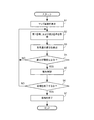
図8は、電子機器10の制御部11の動作を示すフローチャートである。図8には、光学方式により、速度測定装置30を検出する場合の動作が示されている。制御部11は、電子機器10が動作を開始すると、以下で説明する処理を実行する。電子機器10の動作の開始の契機は特に問わないが、例えば、電子機器10の電源がオンされたこと、またはルート案内機能の実行が開始されたことを契機とするとよい。
<1-2. Operation of the first embodiment>
Next, the operation of this embodiment will be described.
<1-2-1. Notification by optical method>
FIG. 8 is a flowchart showing the operation of the control unit 11 of the electronic device 10. FIG. 8 shows an operation when the speed measuring device 30 is detected by an optical method. When the electronic device 10 starts operating, the control unit 11 executes the process described below. The trigger for starting the operation of the electronic device 10 is not particularly limited, but for example, it may be triggered when the power of the electronic device 10 is turned on or the execution of the route guidance function is started.

制御部11は、まず、表示部13へのマップ画面の表示を開始する(ステップS1)。マップ画面は、地図上に自車位置を示した画面である。表示部13に表示される地図は、地図データとGPS受信部16からの位置情報とに基づいて特定される。自車位置は、GPS受信部16からの位置情報に基づいて特定される。図9は、マップ画面の一例を示す図である。図9に示すマップ画面は、地図M上に自車位置を示すアイコンI1が配置されている。なお、マップ画面には、現在位置の住所や、所定の報知対象物までの距離(ここでは、「Hシステムまで1960m」)、制限速度および速度取締地点周辺の写真が表示されている。図10は、マップ画面の他の例を示す図である。図10に示すマップ画面にも、地図M上に自車位置を示すアイコンI1が配置されている。以下、図10に示すマップ画面が表示されているときの制御の例を説明する。なお、アイコンは、文字、記号、図形、その他のオブジェクトに代えられてもよい。 The control unit 11 first starts displaying the map screen on the display unit 13 (step S1). The map screen is a screen showing the position of the own vehicle on the map. The map displayed on the display unit 13 is specified based on the map data and the position information from the GPS receiving unit 16. The own vehicle position is specified based on the position information from the GPS receiving unit 16. FIG. 9 is a diagram showing an example of a map screen. On the map screen shown in FIG. 9, an icon I1 indicating the position of the own vehicle is arranged on the map M. On the map screen, the address of the current position, the distance to the predetermined notification target (here, "1960 m to the H system"), the speed limit, and the photograph around the speed control point are displayed. FIG. 10 is a diagram showing another example of the map screen. Also on the map screen shown in FIG. 10, an icon I1 indicating the position of the own vehicle is arranged on the map M. Hereinafter, an example of control when the map screen shown in FIG. 10 is displayed will be described. The icon may be replaced with a character, a symbol, a figure, or other object.

次に、制御部11は、受光部12から、第1信号Sig1および第2信号Sig2を取得する(ステップS2)。次に、制御部11は、第1信号Sig1に応じた第1受光量と、第2信号Sig2に応じた第2受光量との差分を算出する(ステップS3)。次に、制御部11は、算出した差分が閾値以上かどうかを判定する(ステップS4)。制御部11は、差分が閾値未満である場合、ステップS4で「NO」と判定し、ステップS2の処理に戻す。この場合、制御部11は、速度測定装置30を検出していないとして、速度測定装置30が存在する旨の報知を行わない。 Next, the control unit 11 acquires the first signal Sig1 and the second signal Sig2 from the light receiving unit 12 (step S2). Next, the control unit 11 calculates the difference between the first received light amount corresponding to the first signal Sig1 and the second received light amount corresponding to the second signal Sig2 (step S3). Next, the control unit 11 determines whether or not the calculated difference is equal to or greater than the threshold value (step S4). If the difference is less than the threshold value, the control unit 11 determines "NO" in step S4 and returns to the process of step S2. In this case, the control unit 11 does not notify that the speed measuring device 30 exists, assuming that the speed measuring device 30 has not been detected.

一方、制御部11は、算出した差分が閾値以上である場合、ステップS4で「YES」と判定し、報知制御を行う(ステップS5)。報知制御は、速度測定装置30の存在を報知する制御である。報知制御は、速度測定装置がすることをユーザに認識させるための警報を発する制御ということができる。報知制御は、ここでは、第1の方法で速度測定装置30の存在をユーザに報知する制御である。報知制御は、例えば、報知画面を表示部13に表示する制御を含む。 On the other hand, when the calculated difference is equal to or greater than the threshold value, the control unit 11 determines "YES" in step S4 and performs notification control (step S5). The notification control is a control for notifying the existence of the speed measuring device 30. The notification control can be said to be a control for issuing an alarm for the user to recognize what the speed measuring device is doing. Here, the notification control is a control for notifying the user of the existence of the speed measuring device 30 by the first method. The notification control includes, for example, a control for displaying the notification screen on the display unit 13.

図11は、報知画面の一例を示す図である。図11に示す報知画面は、上述したマップ画面に、ウィンドウW1を重ねて配置した画面である。ウィンドウW1には、速度測定装置30の存在を示すアイコンM1と、「速度取締地点に近づいています。注意してください。」という、速度測定装置30の存在を示すメッセージが配置されている。アイコンM1は、速度測定装置30が、光学方式に対応していることをユーザが認識できるようなアイコンとなっている。報知制御は、報知音声をスピーカ14から出力する制御を含んでもよい。この場合、制御部11は、スピーカ14から、「レーザーによる速度取締地点に近づいています。注意してください。」という音声を出力するとよい。報知制御は、これら以外の制御を含んでもよく、例えば、発光部23を発光させる制御を含んでもよい。報知制御は、速度測定装置30の存在をユーザが認識できる方法で報知する制御であればよい。 FIG. 11 is a diagram showing an example of the notification screen. The notification screen shown in FIG. 11 is a screen in which the window W1 is superposed on the map screen described above. In the window W1, an icon M1 indicating the existence of the speed measuring device 30 and a message indicating the existence of the speed measuring device 30 such as "You are approaching the speed control point. Please be careful." Are arranged. The icon M1 is an icon that allows the user to recognize that the speed measuring device 30 is compatible with the optical method. The notification control may include a control for outputting the notification voice from the speaker 14. In this case, the control unit 11 may output the voice "The laser speed control point is approaching. Please be careful." From the speaker 14. The notification control may include controls other than these, and may include, for example, a control for causing the light emitting unit 23 to emit light. The notification control may be any control that notifies the presence of the speed measuring device 30 by a method that the user can recognize.

次に、制御部11は、図8の処理を終了するかどうかを判定する(ステップS6)。処理の終了の契機は特に問わないが、例えば、操作部19の操作により電子機器10の電源がオフされたこと、またはルート案内機能が停止されたことを契機とするとよい。ステップS6で「NO」と判定した場合、制御部11は、ステップS2の処理に戻して、上記処理を繰り返す。(ステップS4)。例えば、制御部11は、差分が閾値以上から閾値未満に変化した場合、ステップS4で「NO」と判定し、報知制御を停止する。この場合、制御部11は、図12に示すマップ画面を、表示部13に表示させる。これは、速度取締地点を通過したことを意味するからである。ステップS6で「YES」と判定した場合、制御部11は、図8の処理を終了する(ステップS7)。 Next, the control unit 11 determines whether or not to end the process of FIG. 8 (step S6). The timing of the end of the process is not particularly limited, but for example, the power of the electronic device 10 may be turned off by the operation of the operation unit 19, or the route guidance function may be stopped. If it is determined as "NO" in step S6, the control unit 11 returns to the process of step S2 and repeats the above process. (Step S4). For example, when the difference changes from the threshold value or more to the threshold value or less, the control unit 11 determines “NO” in step S4 and stops the notification control. In this case, the control unit 11 causes the display unit 13 to display the map screen shown in FIG. This is because it means that the speed control point has been passed. If "YES" is determined in step S6, the control unit 11 ends the process of FIG. 8 (step S7).

ここで、上述した方法により、速度測定装置30を検出できる理由を説明する。図6で説明したように、第1波長選択部121は、パルス光Loutがエネルギーを有する特定波長λout(より具体的には、波長λ1aから波長λ1bまでの波長領域)の光を選択して、透過させる。このため、第1信号Sig1は、パルス光Loutが受光されている期間において大きな受光量を示し、それ以外の期間は小さな受光量を示すはずである。ただし、受光部12は、受光の目的とするパルス光Loutだけでなく、外乱光も受光する場合がある。この外乱光が、パルス光と誤認されることがある。外乱光として、例えば、日光が風によって揺らされた樹木の枝葉によって周期的に遮られて到来する光がある。別の外乱光として、信号機や広告などからの周期的に点灯および消灯を繰り返す光、および一定の速度で回転する回転警告灯の光などがある。また、受光部の振動によっても、その受光部が受光する光は変化する。例えば、車両40が桟橋の上など周期的な振動を発生する場所を走行した場合、それによって受光部12(例えば、第1受光素子122)の向きが変化し、日光等の光を、所定の周期でオンオフが繰り返される光として受光してしまう場合がある。このような場合も、第1信号Sig1は比較的大きな受光量を示す。 Here, the reason why the speed measuring device 30 can be detected by the above-mentioned method will be described. As described with reference to FIG. 6, the first wavelength selection unit 121 selects light having a specific wavelength λout (more specifically, a wavelength region from the wavelength λ1a to the wavelength λ1b) in which the pulsed light Lout has energy. Make it transparent. Therefore, the first signal Sigma 1 should show a large amount of light received during the period when the pulsed light Lout is received, and show a small amount of light received during the other period. However, the light receiving unit 12 may receive not only the pulsed light Lout, which is the object of light reception, but also ambient light. This disturbed light may be mistaken for pulsed light. As ambient light, for example, there is light that arrives when sunlight is periodically blocked by the branches and leaves of a tree swayed by the wind. Other disturbance lights include light that is periodically turned on and off from traffic lights and advertisements, and light from a rotating warning light that rotates at a constant speed. Further, the light received by the light receiving unit also changes due to the vibration of the light receiving unit. For example, when the vehicle 40 travels on a place where periodic vibration is generated, such as on a pier, the direction of the light receiving unit 12 (for example, the first light receiving element 122) changes accordingly, and light such as sunlight is emitted to a predetermined value. It may be received as light that is repeatedly turned on and off in a cycle. Even in such a case, the first signal Sigma 1 shows a relatively large amount of received light.

これに対し、第2波長選択部123は、パルス光Loutがエネルギーを有する特定波長λout(本実施形態では、波長λ2aから波長λ2bまでの波長領域)の光を遮断し、それ以外の波長領域の光を透過させる。このため、第2信号Sig2は、パルス光Loutが受光されている期間において、受光量は小さくなる。第2受光素子124は、上記外乱光を受光するが、このような外乱光は一般にエネルギーが分布する波長領域が広い。よって、受光部12が、周期的に点灯および消灯が繰り返される外乱光を受光した場合であっても、第2受光素子124の受光量は大きくなると考えられる。このため、第1信号Sig1の受光量が大きい場合であって、第2信号Sig2の受光量が小さい場合、つまり受光量の差分が閾値以上の場合は、パルス光Loutが受光されたと推定できる。一方、第1信号Sig1の受光量が大きい場合であって、第2信号Sig2の受光量も大きい場合、つまり受光量の差分が閾値未満の場合、パルス光Loutが受光された可能性は低いと推定できる。よって、電子機器10によれば、第1受光素子122および第2受光素子124を用いて光を受光することにより、速度測定装置30の検出の精度の向上が期待できる。 On the other hand, the second wavelength selection unit 123 blocks light having a specific wavelength λout (in this embodiment, a wavelength region from wavelength λ2a to wavelength λ2b) in which the pulsed light Lout has energy, and blocks light in other wavelength regions. Allows light to pass through. Therefore, the amount of light received by the second signal Sig2 becomes small during the period in which the pulsed light Lout is received. The second light receiving element 124 receives the above-mentioned disturbance light, and such disturbance light generally has a wide wavelength region in which energy is distributed. Therefore, even when the light receiving unit 12 receives the ambient light that is periodically turned on and off, it is considered that the light receiving amount of the second light receiving element 124 is large. Therefore, when the received amount of the first signal Sig1 is large and the received amount of the second signal Sig2 is small, that is, when the difference in the received amount is equal to or larger than the threshold value, it can be estimated that the pulsed light Lout is received. On the other hand, when the received amount of the first signal Sigma1 is large and the received amount of the second signal Sigma2 is also large, that is, when the difference in the received amount is less than the threshold value, the possibility that the pulsed light Lout is received is low. Can be estimated. Therefore, according to the electronic device 10, it is expected that the detection accuracy of the speed measuring device 30 will be improved by receiving light using the first light receiving element 122 and the second light receiving element 124.

<1−2−2.レーダー方式による報知>
制御部11は、さらに、マイクロ波受信部15により受信されたマイクロ波に基づいて制御部11は、図8の処理と並行して、図13の処理を実行するとよい。
<1-2-2. Radar notification>
The control unit 11 may further execute the process of FIG. 13 in parallel with the process of FIG. 8 based on the microwave received by the microwave receiving unit 15.

まず、制御部11は、マイクロ波受信部15から、マイクロ波の受信信号を取得する(ステップS11)。次に、制御部11は、マイクロ波の受信信号に基づいて、レーダー方式の速度測定装置の存在の有無を判定する判定処理を行う(ステップS12)。ステップS12において、制御部11は、受信したマイクロ波の周波数帯域に基づいて、速度取締地点が存在するかどうかを判定するとよい。この判定のアルゴリズムについては、例えば特許文献1または2に記載の方法でよく、その説明を省略する。 First, the control unit 11 acquires a microwave reception signal from the microwave reception unit 15 (step S11). Next, the control unit 11 performs a determination process for determining the presence or absence of a radar-type speed measuring device based on the received microwave signal (step S12). In step S12, the control unit 11 may determine whether or not a speed control point exists based on the frequency band of the received microwave. The algorithm for this determination may be, for example, the method described in Patent Document 1 or 2, and the description thereof will be omitted.

次に、制御部11は、判定処理の結果に基づいて、速度測定装置を検出したかどうかを判定する(ステップS13)。ステップS13で「YES」と判定した場合、制御部11は、報知制御を行う(ステップS14)。報知制御は、ここでは、第3の方法で速度測定装置の存在をユーザに報知する制御である。報知制御は、例えば、報知画面を表示部13に表示する制御を含む。図14は、報知画面の一例を示す図である。図14に示す報知画面は、上述したマップ画面に、ウィンドウW2を重ねて配置した画面である。ウィンドウW2には、速度測定装置30の存在を示すアイコンM2と、「速度取締地点に近づいています。注意してください。」という、速度測定装置の存在を示すメッセージが配置されている。アイコンM2は、速度取締装置が、レーダー方式に対応していることをユーザが認識できるようなアイコンとなっている。すなわち、アイコンM2は、アイコンM1とは異なる。なお、報知制御は、報知音声をスピーカ14から出力する制御を含んでもよい。この場合、制御部11は、スピーカ14から、「レーダーによる速度取締地点に近づいています。注意してください。」という音声を出力するとよい。報制御報は、これら以外の制御でもよく、例えば、発光部23を発光させる制御を含んでもよい。ここにおいても、報知制御は、速度測定装置の存在をユーザが認識できる方法で報知する制御であればよい。 Next, the control unit 11 determines whether or not the speed measuring device has been detected based on the result of the determination process (step S13). If it is determined as "YES" in step S13, the control unit 11 performs notification control (step S14). Here, the notification control is a control for notifying the user of the existence of the speed measuring device by a third method. The notification control includes, for example, a control for displaying the notification screen on the display unit 13. FIG. 14 is a diagram showing an example of the notification screen. The notification screen shown in FIG. 14 is a screen in which the window W2 is superposed on the map screen described above. In the window W2, an icon M2 indicating the existence of the speed measuring device 30 and a message indicating the existence of the speed measuring device such as "You are approaching the speed control point. Please be careful." Are arranged. The icon M2 is an icon that allows the user to recognize that the speed control device is compatible with the radar system. That is, the icon M2 is different from the icon M1. The notification control may include a control for outputting the notification voice from the speaker 14. In this case, the control unit 11 may output the voice "The speed control point by the radar is approaching. Please be careful." From the speaker 14. The information control information may be a control other than these, and may include, for example, a control for causing the light emitting unit 23 to emit light. Here, too, the notification control may be any control that notifies the existence of the speed measuring device by a method that the user can recognize.

<1−3.第1実施形態の変形例>
制御部11は、さらに以下の制御を行ってもよい。
<1−3−1.パルスの数に応じた報知>
速度測定装置30がパルス波形の光を発する場合、パルスの数を参照することも、速度測定装置30を検出する上で有用である。図15は、電子機器10が受光するパルス光Loutの波形の一例を示す図である。図15(a)は、電子機器10と速度測定装置30との距離が比較的大きい場合、図15(b)は、電子機器10と速度測定装置30との距離が比較的小さい場合を示す。図15(a)に示すように、速度測定装置30と電子機器10との距離が比較的大きい場合、電子機器10の方向に進むパルス光Loutは受光できるが、道路のうち速度測定装置30に近接する位置(例えば、速度測定装置30の真横)のみを伝搬する方向のパルス光は受信されない。よって、パルス光Loutの受光期間Rx1が、不受光期間Rx2に対して相対的に短くなる。図15(b)に示すように、速度測定装置30と電子機器10との距離が比較的小さい場合、電子機器10の方向に進むパルス光Loutは受光でき、また、道路のうち速度測定装置30に近接する位置のみを伝搬する方向のパルス光も受光できる。よって、パルス光Loutの受光期間Rx1が、不受光期間Rx2に対して相対的に長くなる。また、車両40が速度測定装置30の位置を通過した直後も、パルスの数は減ると考えられる。なお、実際にはRx1<<Rx2の関係を満たすことがある。
<1-3. Modification example of the first embodiment>
The control unit 11 may further perform the following control.
<1-3-1. Notification according to the number of pulses>
When the speed measuring device 30 emits light having a pulse waveform, it is also useful to refer to the number of pulses in detecting the speed measuring device 30. FIG. 15 is a diagram showing an example of the waveform of the pulsed light Lout received by the electronic device 10. FIG. 15A shows a case where the distance between the electronic device 10 and the speed measuring device 30 is relatively large, and FIG. 15B shows a case where the distance between the electronic device 10 and the speed measuring device 30 is relatively small. As shown in FIG. 15A, when the distance between the speed measuring device 30 and the electronic device 10 is relatively large, the pulsed light Lout traveling in the direction of the electronic device 10 can be received, but the speed measuring device 30 on the road can receive the pulse light Lout. Pulsed light in a direction propagating only in a close position (for example, right beside the velocity measuring device 30) is not received. Therefore, the light receiving period Rx1 of the pulsed light Lout is relatively shorter than the non-light receiving period Rx2. As shown in FIG. 15B, when the distance between the speed measuring device 30 and the electronic device 10 is relatively small, the pulsed light Lout traveling in the direction of the electronic device 10 can be received, and the speed measuring device 30 on the road. It can also receive pulsed light in the direction propagating only at a position close to. Therefore, the light receiving period Rx1 of the pulsed light Lout is relatively longer than the non-light receiving period Rx2. Further, it is considered that the number of pulses decreases immediately after the vehicle 40 passes the position of the speed measuring device 30. Actually, the relationship of Rx1 << Rx2 may be satisfied.

そこで、制御部11は、パルスの数に応じた報知制御を行ってもよい。制御部11は、例えば、パルス光の受光期間に含まれるパルスの数に応じて、報知レベルを変化させてもよい。報知レベルは、報知の内容がどの程度ユーザにとって重要であるかの指標であり、本実施形態では、警報レベルと換言されてもよい。制御部11は、少なくとも第1受光素子122の受光量に基づいて、パルスの数を特定する。例えば、制御部11は、パルスの数が閾値以上である期間、またはパルスの数が増加している期間は、速度測定装置30に接近しているので、報知レベルを高くする。制御部11は、パルスの数が閾値未満である期間、またはパルス幅の数が減少している期間は、速度測定装置30から遠いか、または遠ざかっているので、報知レベルを低くする。制御部11は、報知レベルに応じて報知の方法を異ならせる。制御部11は、例えば、報知レベルに応じて、表示部13に表示させるメッセージを変化させ、スピーカ14から出力させる報知音声を変化させ、または発光部23の発光色を変化させるとよい。 Therefore, the control unit 11 may perform notification control according to the number of pulses. The control unit 11 may change the notification level according to, for example, the number of pulses included in the light receiving period of the pulsed light. The notification level is an index of how important the content of the notification is to the user, and may be paraphrased as the alarm level in the present embodiment. The control unit 11 specifies the number of pulses based on at least the amount of light received by the first light receiving element 122. For example, the control unit 11 raises the notification level because it is close to the speed measuring device 30 during the period when the number of pulses is equal to or higher than the threshold value or the period when the number of pulses is increasing. The control unit 11 lowers the notification level because it is far from or away from the speed measuring device 30 during the period when the number of pulses is less than the threshold value or the period when the number of pulse widths is decreasing. The control unit 11 changes the notification method according to the notification level. For example, the control unit 11 may change the message to be displayed on the display unit 13, change the notification sound output from the speaker 14, or change the emission color of the light emitting unit 23 according to the notification level.

また、制御部11は、パルス幅の数から距離を推定して、その距離に応じた報知するとよい。例えば、図16に示すように、制御部11は、パルス幅の数から速度測定装置30の位置を推定して、地図上に表示するとよい。この例では、アイコンPが速度測定装置30の位置を示す。以上のように、制御部11は、ユーザに対して受光部12と速度測定装置30との位置関係に応じた報知をすることができる。 Further, the control unit 11 may estimate the distance from the number of pulse widths and notify according to the distance. For example, as shown in FIG. 16, the control unit 11 may estimate the position of the speed measuring device 30 from the number of pulse widths and display it on the map. In this example, the icon P indicates the position of the speed measuring device 30. As described above, the control unit 11 can notify the user according to the positional relationship between the light receiving unit 12 and the speed measuring device 30.

ところで、図17に示すように、車両40の前方に他の車両が存在する場合、前方を走行する車両Cによってパルス光Loutの全部または一部が妨げられてしまう可能性がある。この場合、パルスの数を参照しても、正確に位置関係を特定できない場合がある。そこで、制御部11は、車両40から所定範囲内、ここでは、前方の他の車両Cの存在の有無を検出する。制御部11は、他の車両Cが存在しない場合はパルスの数に応じた報知制御を行い、車両Cが存在する場合はその報知制御を停止するとよい。パルスの数に応じた報知する制御を停止することは、パルスの数に応じて報知に関する制御の内容を変化させないようにすることをいってよい。また、電子機器10は、車間距離が閾値未満である場合はパルスの数に応じた報知制御を停止し、閾値以上である場合はこの報知制御を行ってもよい。車両Cの検出の方法は特に問わないが、車載カメラ50を用いる方法がある。車載カメラ50は、例えばドライブレコーダに用いられるカメラであり、ここでは車両40の前方を撮像する。 By the way, as shown in FIG. 17, when another vehicle is present in front of the vehicle 40, the vehicle C traveling in front may obstruct all or part of the pulsed light Lout. In this case, the positional relationship may not be accurately specified even by referring to the number of pulses. Therefore, the control unit 11 detects the presence or absence of another vehicle C in front of the vehicle 40 within a predetermined range. When the other vehicle C does not exist, the control unit 11 may perform notification control according to the number of pulses, and when the vehicle C exists, the control unit 11 may stop the notification control. It may be said that stopping the control for notifying according to the number of pulses does not change the content of the control for notifying according to the number of pulses. Further, the electronic device 10 may stop the notification control according to the number of pulses when the inter-vehicle distance is less than the threshold value, and may perform this notification control when the distance is equal to or more than the threshold value. The method of detecting the vehicle C is not particularly limited, but there is a method of using the in-vehicle camera 50. The in-vehicle camera 50 is a camera used for, for example, a drive recorder, and here, the front of the vehicle 40 is imaged.

図18は、この場合の電子機器10の制御部11の動作を示すフローチャートである。制御部11は、車載カメラ50から、通信部17を介して撮像画像を取得する(ステップS21)。次に、制御部11は、撮像画像を解析する(ステップS22)。撮像画像の解析のアルゴリズムは問わないが、例えばパターンマッチング法がある。そして、制御部11は、前方に車両があるかどうかを判定する(ステップS23)。ステップS23で「NO」と判定した場合は、制御部11は、パルスの数に応じた報知制御を行うと判定する(ステップS24)。この場合、制御部11は、フラグを、パルスの数に応じた制御を行う旨の値に書き換えるなどの処理を行う。ステップS23で「YES」と判定した場合は、制御部11はパルスの数に応じた報知制御を停止すると判定する(ステップS25)。この場合、制御部11は、所定のフラグを、パルスの数に応じた制御を行わない旨の値に書き換えるなどの処理を行う。ここでは、車両40の前方の車両を検出していたが、車両40の後方などでもよい。なお、電子機器10が車載カメラ50を内蔵していてもよい。以上により、他の車両Cの存在を原因として受光部12と速度測定装置30との位置関係を誤認する可能性が低くなる。 FIG. 18 is a flowchart showing the operation of the control unit 11 of the electronic device 10 in this case. The control unit 11 acquires an captured image from the vehicle-mounted camera 50 via the communication unit 17 (step S21). Next, the control unit 11 analyzes the captured image (step S22). The algorithm for analyzing the captured image does not matter, but there is, for example, a pattern matching method. Then, the control unit 11 determines whether or not there is a vehicle in front (step S23). If it is determined as "NO" in step S23, the control unit 11 determines that the notification control is performed according to the number of pulses (step S24). In this case, the control unit 11 performs processing such as rewriting the flag to a value indicating that control is performed according to the number of pulses. If it is determined as "YES" in step S23, the control unit 11 determines that the notification control according to the number of pulses is stopped (step S25). In this case, the control unit 11 performs processing such as rewriting the predetermined flag to a value indicating that control is not performed according to the number of pulses. Here, the vehicle in front of the vehicle 40 was detected, but it may be behind the vehicle 40 or the like. The electronic device 10 may include an in-vehicle camera 50. As described above, the possibility of misidentifying the positional relationship between the light receiving unit 12 and the speed measuring device 30 due to the presence of another vehicle C is reduced.

<1−3−2.パルス幅またはパルス間隔に応じた制御>
速度測定装置30がパルス光を発する場合、パルス幅またはパルス間隔を参照することも、速度測定装置30を検出する上で有用である。速度測定装置30は、特定波長のパルス光を、所定のデューティー比で発する。また、安全上の観点から、パルス光のデューティー比は所定値未満に設定される。そこで、制御部11は、あらかじめ決められたパルス幅またはパルス間隔と、受光した光のパルス幅またはパルス間隔とに基づいて、速度測定装置30が存在するかどうかを判定するとよい。例えば、制御部11は、基準となるパルス幅またはパルス間隔から一定範囲内に含まれている場合は、速度測定装置30が存在すると判定するが、それ以外の場合は存在しないと判定する。制御部11は、少なくとも第1受光素子122の受光量に基づいて、パルス幅またはパルス間隔を特定する。以上のように、制御部11は、外乱光を発光装置からの光と誤認した報知を減らすことができる。
<1-3-2. Control according to pulse width or pulse interval>
When the speed measuring device 30 emits pulsed light, it is also useful to refer to the pulse width or the pulse interval in detecting the speed measuring device 30. The speed measuring device 30 emits pulsed light having a specific wavelength at a predetermined duty ratio. Further, from the viewpoint of safety, the duty ratio of the pulsed light is set to less than a predetermined value. Therefore, the control unit 11 may determine whether or not the speed measuring device 30 exists based on the predetermined pulse width or pulse interval and the pulse width or pulse interval of the received light. For example, the control unit 11 determines that the speed measuring device 30 exists when it is included within a certain range from the reference pulse width or pulse interval, but determines that it does not exist in other cases. The control unit 11 specifies the pulse width or the pulse interval based on at least the amount of light received by the first light receiving element 122. As described above, the control unit 11 can reduce the notification that the ambient light is mistaken for the light from the light emitting device.

<1−3−3.パルス光の強度に応じた制御>
受光した光のパルス光の強度を参照することも、速度測定装置30を検出する上で有用である。車両40が速度測定装置30に近づくほどパルス光の強度は大きくなり、遠ざかると距離は小さくなる。そこで、制御部11は、第1受光素子122におけるパルス光の受光量に応じて、報知レベルを変化させてもよい。例えば、制御部11は、パルス光の強度が増加している場合は、報知レベルを高くし、減少している場合は報知レベルを低くして、報知するとよい。また、制御部11は、パルス光の受光量が閾値未満である場合、速度測定装置30が存在しないと判定するとよい。以上のように、制御部11は、ユーザに対して受光部12と速度測定装置30との位置関係に応じた報知をすることができる。
<1-3-3. Control according to the intensity of pulsed light>
It is also useful to refer to the intensity of the pulsed light of the received light in detecting the speed measuring device 30. The closer the vehicle 40 is to the speed measuring device 30, the stronger the intensity of the pulsed light, and the farther away the vehicle 40 is, the smaller the distance is. Therefore, the control unit 11 may change the notification level according to the amount of pulsed light received by the first light receiving element 122. For example, the control unit 11 may raise the notification level when the intensity of the pulsed light is increasing, and lower the notification level when the intensity of the pulsed light is decreasing. Further, when the received amount of pulsed light is less than the threshold value, the control unit 11 may determine that the speed measuring device 30 does not exist. As described above, the control unit 11 can notify the user according to the positional relationship between the light receiving unit 12 and the speed measuring device 30.

外乱光として、車間センサで例示される、他車両の検出用のセンサで使用される光も存在し得る。このような光では、パルス光Loutと同じ周波数の光が用いられることもありうる。このような場合でも、電子機器10が受光した光のパルス間隔またはパルス光の強度を参照することにより、誤報知の可能性が低くなることが期待できる。 As the ambient light, there may also be light used in a sensor for detecting another vehicle, which is exemplified by an inter-vehicle sensor. In such light, light having the same frequency as the pulsed light Lout may be used. Even in such a case, it can be expected that the possibility of false alarm is reduced by referring to the pulse interval of the light received by the electronic device 10 or the intensity of the pulsed light.

<1−3−4.撮像の有無の報知>
制御部11は、報知制御を行った後、あらかじめ決められた光が検出されたか否かに応じて、撮像されたことまたは撮像されていないことを報知する制御を行ってもよい。撮像部32による撮像が行われた場合、ストロボ33が発光する。そこで、制御部11は、報知制御を行った後、さらに、ストロボ33の光を検出した場合は撮像された旨を報知するとよい。または、制御部11は、報知制御を行った後、ストロボ33の光を検出しなかった場合、撮像されていない旨を報知するとよい。これにより、ユーザは車両40が撮像されたかどうかを把握できる。なお、ストロボ33からの受光は、受光部12を用いて行ってもよいし、別の受光部を用いてもよい。
<1-3-4. Notification of presence / absence of imaging>
After performing the notification control, the control unit 11 may perform control to notify that the image has been captured or that the light has not been captured, depending on whether or not a predetermined light has been detected. When an image is taken by the image pickup unit 32, the strobe 33 emits light. Therefore, after performing the notification control, the control unit 11 may further notify that the image has been taken when the light of the strobe 33 is detected. Alternatively, if the control unit 11 does not detect the light of the strobe 33 after performing the notification control, it may notify that the image has not been taken. This allows the user to know whether the vehicle 40 has been imaged. The light receiving from the strobe 33 may be performed by using the light receiving unit 12, or another light receiving unit may be used.

[2.第2実施形態]
この実施形態では、電子機器10は、パルス光およびマイクロ波を受信しない場合でも、速度測定装置30の存在を報知する機能を有する。この実施形態の電子機器は、上述した第1実施形態の機能の一部または全部を有するとよいし、有しなくてもよい。
[2. Second Embodiment]
In this embodiment, the electronic device 10 has a function of notifying the presence of the speed measuring device 30 even when the pulsed light and the microwave are not received. The electronic device of this embodiment may or may not have a part or all of the functions of the first embodiment described above.

<2−1.第2実施形態の構成>
図19は、本実施形態のシステムの概要を説明する図であり。図19に示すように、道路には様々な種別がある。例えば、グリーンベルトと呼ばれる通学路にも使用される道路Ar1においては、車両40の速度制限を守ることが特に重要視され、速度測定装置30が設置される可能性が、それ以外の種別の道路Ar2よりも高いと考えられる。そこで、制御部11は、電子機器10があらかじめ決められた種類の道路上に位置する場合に、速度測定装置30の存在を報知するとよい。
<2-1. Configuration of the second embodiment>
FIG. 19 is a diagram illustrating an outline of the system of the present embodiment. As shown in FIG. 19, there are various types of roads. For example, on the road Ar1 that is also used for school roads called green belts, it is particularly important to observe the speed limit of the vehicle 40, and there is a possibility that the speed measuring device 30 will be installed on other types of roads. It is considered to be higher than Ar2. Therefore, the control unit 11 may notify the presence of the speed measuring device 30 when the electronic device 10 is located on a road of a predetermined type.

<2−2.第2実施形態の動作>
図20は、電子機器10の制御部11の動作を示すフローチャートである。制御部11は、GPS受信部16から位置情報を取得する(ステップS31)。次に、制御部11は、位置情報が示す現在位置が所定エリア内かどうかを判定する(ステップS32)。ここでは、制御部11は、現在位置と記憶部18に記憶されたデータとに基づいて、車両40がグリーンベルト上であるかどうかを判定する。制御部11は、ステップS32で「YES」と判定した場合、報知制御を行う(ステップS33)。報知制御は、例えば、報知画面を表示部13に表示する制御を含む。
<2-2. Operation of the second embodiment>
FIG. 20 is a flowchart showing the operation of the control unit 11 of the electronic device 10. The control unit 11 acquires position information from the GPS receiving unit 16 (step S31). Next, the control unit 11 determines whether or not the current position indicated by the position information is within the predetermined area (step S32). Here, the control unit 11 determines whether or not the vehicle 40 is on the green belt based on the current position and the data stored in the storage unit 18. When the control unit 11 determines "YES" in step S32, the control unit 11 performs notification control (step S33). The notification control includes, for example, a control for displaying the notification screen on the display unit 13.

図21は、報知画面の一例を示す図である。図21に示す報知画面は、上述したマップ画面に、ウィンドウW3を重ねて配置した画面である。ウィンドウW3には、速度測定装置30の存在を示すアイコンM3と、「速度取締の注意エリア内です。」という、速度測定装置の存在を示すメッセージが配置されている。アイコンM3は、速度取締地点が、位置情報により行われていることをユーザが認識できるようなアイコンとなっている。すなわち、例えばアイコンM3は、アイコンM1,M2とは異なる。なお、報知制御は、報知音声をスピーカ14から出力する制御を含んでもよい。この場合、制御部11は、スピーカ14から「速度取締の注意エリア内です。」という音声を出力するとよい。報知制御は、これら以外の制御を含んでもよく、例えば、発光部23を発光させる制御を含んでもよい。なお、所定のエリアは、グリーンベルトに限られず、一方通行の道路や、その他の種別の道路であってもよい。 FIG. 21 is a diagram showing an example of a notification screen. The notification screen shown in FIG. 21 is a screen in which the window W3 is superposed on the map screen described above. In the window W3, an icon M3 indicating the existence of the speed measuring device 30 and a message indicating the existence of the speed measuring device such as "It is in the caution area for speed control" are arranged. The icon M3 is an icon that allows the user to recognize that the speed control point is performed based on the position information. That is, for example, the icon M3 is different from the icons M1 and M2. The notification control may include a control for outputting the notification voice from the speaker 14. In this case, the control unit 11 may output the voice "It is within the caution area for speed control" from the speaker 14. The notification control may include controls other than these, and may include, for example, a control for causing the light emitting unit 23 to emit light. The predetermined area is not limited to the green belt, and may be a one-way road or another type of road.

このようにすれば、位置情報に基づいて発光装置の存在を報知できるので、速度測定装置30からのパルス光を受光しなくとも、その存在を報知することができる。 In this way, the existence of the light emitting device can be notified based on the position information, so that the existence can be notified without receiving the pulsed light from the speed measuring device 30.

[3.第3実施形態]
この実施形態では、電子機器10は、パルス光を受光する受光部を複数有する。
[3. Third Embodiment]
In this embodiment, the electronic device 10 has a plurality of light receiving units that receive pulsed light.

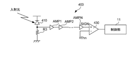
図22は、電子機器10の電気的な構成を示すブロック図である。この例では、電子機器10は、受光部12A、12B,12Cの3つを備えている。受光部12A,12B,12Cの各構成は、波長選択部の特性を除き、受光部12と同じでよい。なお、図22では、図6で説明した表示部13〜ケーブル端子部24の図示を省略してある。 FIG. 22 is a block diagram showing an electrical configuration of the electronic device 10. In this example, the electronic device 10 includes three light receiving units 12A, 12B, and 12C. Each configuration of the light receiving unit 12A, 12B, 12C may be the same as that of the light receiving unit 12 except for the characteristics of the wavelength selection unit. In FIG. 22, the display unit 13 to the cable terminal unit 24 described with reference to FIG. 6 are not shown.

図23は、この実施形態の受光部12A,12B,12Cの第1波長選択部121、およびの第2波長選択部123の特性を示す図である。図23(a)は受光部12A、図23(b)は受光部12B、図23(c)は受光部12Cに対応する。図23(a)〜(c)に示すように、受光部12A,12B,12Cの各々で、受光の目的とするパルス光の波長が異なる。図23(a)に実線で示すように、受光部12Aの第1波長選択部121は、特定波長λout1を含む波長領域、ここでは波長λ11aから波長λ11bまでの波長領域の光を透過させ、これとは異なる波長領域の光を遮断する。第2波長選択部123は、図23(a)に破線で示すように、特定波長λout1を含む波長領域、ここでは波長λ21aから波長λ21bまでの波長領域の光を遮断し、これとは異なる波長領域の光を透過させる。図23(b)に実線で示すように、受光部12Bの第1波長選択部121は、特定波長λout2を含む波長領域、ここでは波長λ12aから波長λ12bまでの波長領域の光を透過させ、これとは異なる波長領域の光を遮断する。第2波長選択部123は、図23(b)に破線で示すように、特定波長λout2を含む波長領域、ここでは波長λ22aから波長λ22bまでの波長領域の光を遮断し、これとは異なる波長領域の光を透過させる。図23(c)に実線で示すように、受光部12Cの第1波長選択部121は、特定波長λout3を含む波長領域、ここでは波長λ13aから波長λ13bまでの波長領域の光を透過させ、これとは異なる波長領域の光を遮断する。第2波長選択部123は、図23(c)に破線で示すように、特定波長λout3を含む波長領域、ここでは波長λ23aから波長λ23bまでの波長領域の光を遮断し、これとは異なる波長領域の光を透過させる。λout1,out2,out3は、例えば、850nm,905nm,950nmであるが、これらに限られず、1900nmなどとしてもよい。 FIG. 23 is a diagram showing the characteristics of the first wavelength selection unit 121 and the second wavelength selection unit 123 of the light receiving units 12A, 12B, and 12C of this embodiment. FIG. 23 (a) corresponds to the light receiving unit 12A, FIG. 23 (b) corresponds to the light receiving unit 12B, and FIG. 23 (c) corresponds to the light receiving unit 12C. As shown in FIGS. 23 (a) to 23 (c), the wavelength of the pulsed light to be received is different in each of the light receiving units 12A, 12B, and 12C. As shown by a solid line in FIG. 23A, the first wavelength selection unit 121 of the light receiving unit 12A transmits light in a wavelength region including a specific wavelength λout1, in this case, a wavelength region from the wavelength λ11a to the wavelength λ11b. Blocks light in a wavelength region different from that of. As shown by a broken line in FIG. 23A, the second wavelength selection unit 123 blocks light in a wavelength region including a specific wavelength λout1, here in a wavelength region from wavelength λ21a to wavelength λ21b, and has a wavelength different from this. Transmits light in the area. As shown by a solid line in FIG. 23B, the first wavelength selection unit 121 of the light receiving unit 12B transmits light in a wavelength region including a specific wavelength λout2, in this case, a wavelength region from the wavelength λ12a to the wavelength λ12b. Blocks light in a wavelength region different from that of. As shown by a broken line in FIG. 23B, the second wavelength selection unit 123 blocks light in a wavelength region including a specific wavelength λout2, in which wavelength region from wavelength λ22a to wavelength λ22b, and has a wavelength different from this. Transmits light in the area. As shown by a solid line in FIG. 23 (c), the first wavelength selection unit 121 of the light receiving unit 12C transmits light in a wavelength region including a specific wavelength λout3, in which a wavelength region from wavelength λ13a to wavelength λ13b is transmitted. Blocks light in a wavelength region different from that of. As shown by a broken line in FIG. 23 (c), the second wavelength selection unit 123 blocks light in a wavelength region including a specific wavelength λout3, in which wavelength region from wavelength λ23a to wavelength λ23b, and has a wavelength different from this. Transmits light in the area. λout1, out2, and out3 are, for example, 850 nm, 905 nm, and 950 nm, but are not limited to these, and may be 1900 nm.

制御部11は、受光部12A,12B,12Cのいずれかからの第1信号Sig1および第2信号Sig2に基づいて、速度測定装置30を検出した場合、速度測定装置30が存在することを報知する。この実施形態によれば、電子機器10が発する光の波長が異なる速度測定装置30が複数存在するか、または速度測定装置30の発する光の波長が変更された場合でも、速度測定装置30の存在を報知することができる。 When the speed measuring device 30 is detected based on the first signal Sigma1 and the second signal Sigma2 from any of the light receiving units 12A, 12B, and 12C, the control unit 11 notifies that the speed measuring device 30 exists. .. According to this embodiment, even if there are a plurality of speed measuring devices 30 having different wavelengths of light emitted by the electronic device 10, or the wavelength of light emitted by the speed measuring device 30 is changed, the speed measuring device 30 is present. Can be notified.

複数の受光部12の特性を同一にしてもよい。この場合において、図24に示すように、車両40の異なる位置に受光部12A,12B,12Cが設けられてもよい。ここでは、受光部12Aは左前方部、受光部12Bは中央前方部、受光部12Cは右前方部に設けられる。これにより、受光部12A,12B,12Cにおけるレーザーの受光タイミングに基づいて、レーザーの到来方向を推定することもできる。例えば左前方から到来すれば受光部12Aの受光タイミング、右前方から到来すれば受光部12Cの受光タイミングが相対的に早くなる。さらに、制御部11は、パルス光が到来した方向を、ユーザに報知するとよい。 The characteristics of the plurality of light receiving units 12 may be the same. In this case, as shown in FIG. 24, the light receiving units 12A, 12B, and 12C may be provided at different positions of the vehicle 40. Here, the light receiving portion 12A is provided on the left front portion, the light receiving portion 12B is provided on the center front portion, and the light receiving portion 12C is provided on the right front portion. Thereby, the arrival direction of the laser can be estimated based on the light receiving timing of the laser in the light receiving units 12A, 12B, and 12C. For example, if it arrives from the left front, the light receiving timing of the light receiving unit 12A is relatively early, and if it arrives from the right front, the light receiving timing of the light receiving unit 12C is relatively early. Further, the control unit 11 may notify the user of the direction in which the pulsed light has arrived.

また、速度測定部31は、一定速度で回転するミラーにパルス光を射出し、このミラーが反射したパルス光Loutを出射する。このため、受光部12A,12B,12Cのそれぞれでパルス光Loutの受光タイミングには、例えば、ミラーの回転速度、受光部12A,12B,12Cの位置、および受光部12A,12B,12Cと速度測定装置30との距離に応じた差異が現れる。そこで、制御部11は、受光部12A,12B,12Cにおけるパルス光Loutの受光タイミングに基づいて、速度測定装置30を検出してもよい。 Further, the speed measuring unit 31 emits pulsed light to a mirror rotating at a constant speed, and emits pulsed light Lout reflected by the mirror. Therefore, for the light receiving timing of the pulsed light Lout in each of the light receiving units 12A, 12B, 12C, for example, the rotation speed of the mirror, the positions of the light receiving units 12A, 12B, 12C, and the speed measurement of the light receiving units 12A, 12B, 12C. A difference appears depending on the distance from the device 30. Therefore, the control unit 11 may detect the speed measuring device 30 based on the light receiving timing of the pulsed light Lout in the light receiving units 12A, 12B, and 12C.

受光部12A,12B,12Cは、それぞれ受光する光の方向が異なっていてもよい。例えば、受光部12A,12B,12Cの間で、受光素子の向きを20度ずつ異ならせてもよい。これにより、速度測定装置30の設置位置による検出精度の低下を抑えることができる可能性がある。なお、この実施形態において、受光部の数を2つまたは4つ以上とするとよい。 The light receiving units 12A, 12B, and 12C may receive different directions of light. For example, the orientation of the light receiving element may be different by 20 degrees between the light receiving units 12A, 12B, and 12C. As a result, there is a possibility that a decrease in detection accuracy due to the installation position of the speed measuring device 30 can be suppressed. In this embodiment, the number of light receiving units may be two or four or more.

[4.受光部12の構成]
次に、上述した各実施形態に適用可能な受光部12の構成例を説明する。
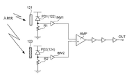
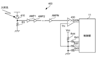
図25は、受光部12の回路構成例を示す図である。第1受光素子122は、ここではフォトダイオードPD1である。フォトダイオードPD1には、第1波長選択部121を介した光が受光面に入射する。PD1のカソードは高電位側の電源ラインと接続され、アノードは抵抗R1の一端と接続する。抵抗R1の他端は接地されている。出力制御回路A1の入力端は、フォトダイオードPD1のアノードと抵抗R1の一端とに共通に接続されている。出力制御回路A1の出力端は、差動増幅器AMPの負極側の入力端子に接続されている。出力制御回路A1は、例えば信号のレベルを調整するアンプである。第2受光素子124は、ここではフォトダイオードPD2である。フォトダイオードPD2には、第2波長選択部123を介した光が受光面に入射する。フォトダイオードPD2のカソードは高電位側の電源ラインと接続され、アノードは抵抗R2の一端と接続する。抵抗R2の他端は接地されている。出力制御回路A2の入力端は、フォトダイオードPD2のアノードと抵抗R2の一端とに共通に接続されている。出力制御回路A2の出力端は、差動増幅器AMPの正極側の入力端子に接続されている。出力制御回路A2は、例えば信号のレベルを調整するアンプである。差動増幅器AMPの出力端からは、フォトダイオードPD1,PD2の受光量の差分に応じた信号が出力される。制御部11は、この差分に基づいて速度測定装置30を検出する。制御部11は、差動増幅器AMPにより増幅された後の信号に基づいて、速度測定装置30を検出するとよい。
[4. Configuration of light receiving unit 12]
Next, a configuration example of the light receiving unit 12 applicable to each of the above-described embodiments will be described.
FIG. 25 is a diagram showing a circuit configuration example of the light receiving unit 12. The first light receiving element 122 is a photodiode PD1 here. Light passing through the first wavelength selection unit 121 is incident on the light receiving surface of the photodiode PD1. The cathode of PD1 is connected to the power supply line on the high potential side, and the anode is connected to one end of the resistor R1. The other end of the resistor R1 is grounded. The input end of the output control circuit A1 is commonly connected to the anode of the photodiode PD1 and one end of the resistor R1. The output end of the output control circuit A1 is connected to the input terminal on the negative electrode side of the differential amplifier AMP. The output control circuit A1 is, for example, an amplifier that adjusts a signal level. The second light receiving element 124 is a photodiode PD2 here. Light passing through the second wavelength selection unit 123 is incident on the light receiving surface of the photodiode PD2. The cathode of the photodiode PD2 is connected to the power supply line on the high potential side, and the anode is connected to one end of the resistor R2. The other end of the resistor R2 is grounded. The input end of the output control circuit A2 is commonly connected to the anode of the photodiode PD2 and one end of the resistor R2. The output end of the output control circuit A2 is connected to the input terminal on the positive electrode side of the differential amplifier AMP. The output control circuit A2 is, for example, an amplifier that adjusts the signal level. From the output end of the differential amplifier AMP, a signal corresponding to the difference in the amount of light received by the photodiodes PD1 and PD2 is output. The control unit 11 detects the speed measuring device 30 based on this difference. The control unit 11 may detect the speed measuring device 30 based on the signal after being amplified by the differential amplifier AMP.

[5.電子機器10の外観構成]
図26は、電子機器10の外観構成の一例を示す六面図である。この例では、電子機器10の筐体の正面には、表示部13、発光部23およびセンサ部20の照度センサ201が設けられている。筐体100の上端面から音声を出力するように、スピーカ14が設けられている。筐体100の右側端面には、SDカード(登録商標)を装着するための装着部21(すなわち、SDカードスロット)が設けられている。筐体100の背面の右上方部には、受光部12が設けられている。また、筐体100の背面の左下部には、電源部22の電源スイッチ221およびDCジャック222が設けられている。領域104は、機種名およびシリアルナンバーが記される領域である。
[5. Appearance configuration of electronic device 10]
FIG. 26 is a six-view view showing an example of the external configuration of the electronic device 10. In this example, the illuminance sensor 201 of the display unit 13, the light emitting unit 23, and the sensor unit 20 is provided on the front surface of the housing of the electronic device 10. The speaker 14 is provided so as to output sound from the upper end surface of the housing 100. A mounting portion 21 (that is, an SD card slot) for mounting an SD card (registered trademark) is provided on the right end surface of the housing 100. A light receiving portion 12 is provided on the upper right portion of the back surface of the housing 100. Further, a power switch 221 and a DC jack 222 of the power supply unit 22 are provided in the lower left portion of the back surface of the housing 100. The area 104 is an area in which the model name and the serial number are written.

[6.電子機器10が行う報知制御の他の実施形態]
次に、電子機器10が行う情報の報知制御の他の実施形態を説明する。以下の報知制御にあっては、上述した報知制御が適宜組み合わせされてもよい。
<6−1.パルス光Lout(固定式)に関する報知>
制御部11は、固定式の速度測定装置30の存在を報知する第1報知制御を行う。図27は、電子機器10が固定式の速度測定装置30からパルス光Loutを受光したときに表示する報知画面の一例を示す図である。図27に示すように、この報知画面は、地図M11に、車両40の位置を示すアイコンI11、および情報表示領域TA1,TA2,TB1,TB2を重ねて配置した画面である。情報表示領域TA1,TA2は、それぞれパルス光Loutを受光した場合に表示される。情報表示領域TA1は、表示画面における右下部に配置される。情報表示領域TA1は、速度測定装置30の属性および車両40の状態を表示する。情報表示領域TA1は、速度測定装置30の属性として、速度測定装置30が光学方式に対応することを意味する「レーザー」という文字列TA11と、速度測定装置30を模したアイコンTA12を表示する。情報表示領域TA1は、さらに、車両40の状態として、車両40の現在の速度を示す文字列TA13(ここでは、60km/h)を表示する。このようにすれば、電子機器10は、速度測定装置30の属性および車両40の状態の少なくともいずれかの情報をユーザに認識させることができる。速度測定装置の属性は、車両40からの推定距離などその他の属性であってもよい。情報表示領域TA1は、報知レベルを特定できる場合は、報知レベルを表示するとよい。車両40の状態は、速度以外にエンジン回転数などの他の走行状態を示してもよい。
[6. Other Embodiments of Notification Control Performed by Electronic Device 10]
Next, another embodiment of information notification control performed by the electronic device 10 will be described. In the following notification control, the above-mentioned notification control may be appropriately combined.
<6-1. Notification of pulsed light Lout (fixed type)>
The control unit 11 performs the first notification control for notifying the existence of the fixed speed measuring device 30. FIG. 27 is a diagram showing an example of a notification screen displayed when the electronic device 10 receives the pulsed light Lout from the fixed speed measuring device 30. As shown in FIG. 27, this notification screen is a screen in which the icon I11 indicating the position of the vehicle 40 and the information display areas TA1, TA2, TB1 and TB2 are arranged on the map M11 in an overlapping manner. The information display areas TA1 and TA2 are displayed when the pulsed light Lout is received, respectively. The information display area TA1 is arranged at the lower right of the display screen. The information display area TA1 displays the attributes of the speed measuring device 30 and the state of the vehicle 40. The information display area TA1 displays the character string TA11 of "laser" meaning that the speed measuring device 30 corresponds to the optical method and the icon TA12 imitating the speed measuring device 30 as attributes of the speed measuring device 30. The information display area TA1 further displays a character string TA13 (here, 60 km / h) indicating the current speed of the vehicle 40 as the state of the vehicle 40. In this way, the electronic device 10 can make the user recognize at least one of the attributes of the speed measuring device 30 and the state of the vehicle 40. The attributes of the speed measuring device may be other attributes such as the estimated distance from the vehicle 40. When the notification level can be specified, the information display area TA1 may display the notification level. The state of the vehicle 40 may indicate other running states such as the engine speed in addition to the speed.

情報表示領域TA2は、表示画面における左下部に配置される。情報表示領域TA2は、速度測定装置30を模した画像を含むアニメーション画像を表示する。アニメーション画像は、複数枚(コマ)の静止画像を所定の時間間隔で連続的に順次切り替えながら表示することにより、見ている者に画像が動いているような印象を与えることのできる画像である。このようにすれば、電子機器10は、車両40が接近している速度測定装置30が存在することを、ユーザに認識させやすくすることができる。情報表示領域TB1は、表示画面における右上部に配置され、現在位置の住所を表示する。情報表示領域TB2は、表示画面における左上部に配置され、現在時刻を表示する。制御部11は、表示による報知に加え、所定の音声による報知を行うようにするとよい。 The information display area TA2 is arranged at the lower left of the display screen. The information display area TA2 displays an animation image including an image imitating the speed measuring device 30. An animation image is an image that can give the viewer the impression that the image is moving by displaying a plurality of still images (frames) while continuously switching them at predetermined time intervals. .. In this way, the electronic device 10 can easily make the user recognize that the speed measuring device 30 in which the vehicle 40 is approaching exists. The information display area TB1 is arranged in the upper right part of the display screen and displays the address of the current position. The information display area TB2 is arranged in the upper left part of the display screen and displays the current time. The control unit 11 may perform a predetermined voice notification in addition to the display notification.

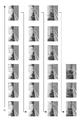
図28および図29は、情報表示領域TA2に表示されるアニメーション画像の一例を示す図である。図28および図29においては、矢印で示す順番で各コマの画像が表示される。図28の最下段の右端のコマの画像が表示されると、次に図29の最上段の左端のコマの画像が表示される。図29の最下段の右端のコマの画像が表示されると、図28における最上段の左端のコマの画像に戻って表示される。図28に示すように、アニメーション画像は、道路脇を示す画像TA21と、速度測定装置を模した画像TA22と、速度測定装置から発せられるパルス光が照射される領域を視覚的に表した画像TA23とを含む。図28および図29に示すように、アニメーション画像にあっては、時間の経過とともに速度測定装置に接近し、最接近した後は速度測定装置から遠く離れた位置から速度測定装置を見た様子を示す画像(破線で囲んだコマを参照)が表示される。そして、アニメーション画像にあっては、再び、時間の経過とともに速度測定装置に接近していく様子が表示される。制御部11は、パルス光Loutを受光している期間は、上述した順番で各コマの画像が表示されるアニメーションを表示させる。制御部11は、光学方式の速度測定装置30の存在を検出しなくなると、直ちにまたは所定時間後に報知を停止する。この所定時間は、例えば3秒間とするとよい。アニメーション画像における最初のコマは、速度測定装置から最も遠く離れた位置から速度測定装置を見た様子を示す画像(破線で囲んだコマを参照)としてもよい。 28 and 29 are diagrams showing an example of an animation image displayed in the information display area TA2. In FIGS. 28 and 29, the images of each frame are displayed in the order indicated by the arrows. When the image of the rightmost frame at the bottom of FIG. 28 is displayed, the image of the leftmost frame at the top of FIG. 29 is displayed next. When the image of the rightmost frame at the bottom of FIG. 29 is displayed, the image of the leftmost frame at the top of FIG. 28 is displayed again. As shown in FIG. 28, the animation images include an image TA21 showing the side of the road, an image TA22 imitating a speed measuring device, and an image TA23 visually representing a region irradiated with pulsed light emitted from the speed measuring device. And include. As shown in FIGS. 28 and 29, in the animated image, the speed measuring device is approached with the passage of time, and after the closest approach, the speed measuring device is viewed from a position far away from the speed measuring device. The image shown (see the frame surrounded by the broken line) is displayed. Then, in the animation image, the appearance of approaching the speed measuring device with the passage of time is displayed again. The control unit 11 displays an animation in which the images of each frame are displayed in the above-mentioned order during the period during which the pulsed light Lout is received. When the control unit 11 ceases to detect the presence of the optical speed measuring device 30, the control unit 11 stops the notification immediately or after a predetermined time. This predetermined time may be, for example, 3 seconds. The first frame in the animation image may be an image (see the frame surrounded by a broken line) showing how the speed measuring device is viewed from the position farthest from the speed measuring device.

<6−2.パルス光Lout(移動式)に関する報知>
制御部11は、移動式の速度測定装置30の存在を報知する第2報知制御を行う。第2報知制御は、第1報知制御とは異なる報知制御である。図30は、電子機器10が移動式の速度測定装置30からパルス光Loutを受光したときに表示する報知画面の一例を示す図である。図30に示すように、この報知画面は、地図M11に、車両40の位置を示すアイコンI11と、情報表示領域TA1,TA3,TB1,TB2を重ねて配置した画面である。情報表示領域TA1,TB1,TB2は、図27で説明した情報表示領域TA1,TB1,TB2と同じである。情報表示領域TA3は、パルス光Loutを受信した場合に表示される。情報表示領域TA3は、表示画面における左下部に配置される。情報表示領域TA1は、速度測定装置30の属性および車両40の状態を表示する。情報表示領域TA3は、速度測定装置30を模した画像を含むアニメーション画像を表示する。制御部11は、表示による報知に加え、所定の音声による報知を行うようにするとよい。なお、さらに、速度測定装置30の位置を示すアイコンが地図M11上に配置されてもよい。
<6-2. Notification of pulsed light Lout (mobile)>
The control unit 11 performs a second notification control for notifying the existence of the mobile speed measuring device 30. The second notification control is a notification control different from the first notification control. FIG. 30 is a diagram showing an example of a notification screen displayed when the electronic device 10 receives the pulsed light Lout from the mobile speed measuring device 30. As shown in FIG. 30, this notification screen is a screen in which the icon I11 indicating the position of the vehicle 40 and the information display areas TA1, TA3, TB1 and TB2 are arranged on the map M11 in an overlapping manner. The information display areas TA1, TB1 and TB2 are the same as the information display areas TA1, TB1 and TB2 described with reference to FIG. 27. The information display area TA3 is displayed when the pulsed light Lout is received. The information display area TA3 is arranged at the lower left of the display screen. The information display area TA1 displays the attributes of the speed measuring device 30 and the state of the vehicle 40. The information display area TA3 displays an animation image including an image imitating the speed measuring device 30. The control unit 11 may perform a predetermined voice notification in addition to the display notification. Further, an icon indicating the position of the speed measuring device 30 may be arranged on the map M11.

図31および図32は、情報表示領域TA3に表示されるアニメーション画像の一例を示す図である。図31および図32においては、矢印で示す順番で各コマの画像が表示される。図31の最下段の右端のコマの画像が表示されると、次に図32の最上段の左端のコマの画像が表示される。図31の最下段の右端のコマの画像が表示されると、図32における最上段の左端のコマの画像に戻って表示される。図31に示すように、アニメーション画像は、画像領域を、斜線を用いて左右に分け、左側の領域には、道路の周辺を示す画像TA31と、速度測定装置を模した画像TA32と、画像TA32をターゲットとし、これを囲むターゲット画像TA33とを配置し、右側の領域には、道路の周辺を示す画像T34と、速度測定装置を模した画像TA35と、画像TA35をターゲットとし、これを囲むターゲット画像TA36とを配置した画像である。図31および図32に示すように、アニメーション画像にあっては、時間の経過とともに速度測定装置に接近するとともに、ターゲット画像TA33,TA36が拡大および縮小を繰り返してそのサイズが周期的に変化する。速度測定装置に最接近した後は、その速度測定装置から遠く離れた位置から速度測定装置を見た様子を示す画像が表示される。そして、再び、時間の経過とともに速度測定装置に接近していく様子が表示される。パルス光Loutを受光している期間は、上述した順番で各コマの画像が表示されるアニメーションが表示される。制御部11は、光学方式の速度測定装置30の存在を検出しなくなると、直ちにまたは所定時間後に報知を停止する。この所定時間は、3秒間とするとよい。アニメーション画像における最初のコマは、速度測定装置から最も遠く離れた位置から速度測定装置を見た様子を示す画像としてもよい。 31 and 32 are diagrams showing an example of an animation image displayed in the information display area TA3. In FIGS. 31 and 32, the images of each frame are displayed in the order indicated by the arrows. When the image of the rightmost frame at the bottom of FIG. 31 is displayed, the image of the leftmost frame at the top of FIG. 32 is displayed next. When the image of the rightmost frame at the bottom of FIG. 31 is displayed, the image of the leftmost frame at the top of FIG. 32 is displayed again. As shown in FIG. 31, in the animation image, the image area is divided into left and right by using diagonal lines, and in the left area, an image TA31 showing the periphery of the road, an image TA32 imitating a speed measuring device, and an image TA32. In the area on the right side, an image T34 showing the periphery of the road, an image TA35 imitating a speed measuring device, and an image TA35 as a target and surrounding the target image TA33 are arranged. It is an image in which the image TA36 is arranged. As shown in FIGS. 31 and 32, in the animation image, the size of the target images TA33 and TA36 changes periodically as they approach the speed measuring device with the passage of time and repeatedly enlarge and reduce the target images TA33 and TA36. After the closest approach to the speed measuring device, an image showing how the speed measuring device is viewed from a position far away from the speed measuring device is displayed. Then, again, the appearance of approaching the speed measuring device with the passage of time is displayed. During the period during which the pulsed light Lout is received, an animation in which the images of each frame are displayed in the above-mentioned order is displayed. When the control unit 11 ceases to detect the presence of the optical speed measuring device 30, the control unit 11 stops the notification immediately or after a predetermined time. This predetermined time is preferably 3 seconds. The first frame in the animation image may be an image showing how the speed measuring device is viewed from the position farthest from the speed measuring device.

<6−3.レーダー方式に関する報知>
制御部11は、マイクロ電波を受信したことに応じて、レーダー方式の速度測定装置の存在を報知する第3報知制御を行う。図33は、電子機器10がレーダー方式の速度測定装置を受光したときの報知画面の一例を示す図である。図33に示すように、この報知画面は、地図M11に、車両40の位置を示すアイコンI11と、レーダー方式の速度測定装置の設置位置を示すアイコンI12と、情報表示領域TA4,TA5,TB1,TB2を重ねて配置した画面である。情報表示領域TB1,TB2は、図27で説明した情報表示領域TB1,TB2と同じである。情報表示領域TA4は、速度測定装置の属性および車両40の状態を表示する。情報表示領域TA4は、速度測定装置の属性として、レーダー方式に対応することを意味する「レーダー」、および速度測定装置からの電波の強度に応じた報知レベルを示す「Lv.5」という文字列TA41と、レーダー方式の速度測定装置であることを示すアイコンTA42とを表示する。情報表示領域TA4は、車両40の状態として、車両40の現在の速度を示す文字列TA43(ここでは、88km/h)を表示する。情報表示領域TA5は、表示画面における左下部に配置される。情報表示領域TA5は、速度測定装置を模した画像を含むアニメーション画像を表示する。制御部11は、表示による報知に加え、所定の音声による報知を行うようにするとよい。
<6-3. Notification of radar system>
The control unit 11 performs a third notification control for notifying the existence of a radar-type speed measuring device in response to receiving the micro radio wave. FIG. 33 is a diagram showing an example of a notification screen when the electronic device 10 receives a light received by the radar type speed measuring device. As shown in FIG. 33, this notification screen has an icon I11 indicating the position of the vehicle 40, an icon I12 indicating the installation position of the radar type speed measuring device, and information display areas TA4, TA5, TB1 on the map M11. It is a screen in which TB2 is arranged in an overlapping manner. The information display areas TB1 and TB2 are the same as the information display areas TB1 and TB2 described with reference to FIG. 27. The information display area TA4 displays the attributes of the speed measuring device and the state of the vehicle 40. The information display area TA4 is an attribute of the speed measuring device, "radar" which means that it corresponds to the radar system, and a character string "Lv.5" which indicates the notification level according to the intensity of the radio wave from the speed measuring device. The TA41 and the icon TA42 indicating that the speed measuring device is a radar type are displayed. The information display area TA4 displays a character string TA43 (here, 88 km / h) indicating the current speed of the vehicle 40 as the state of the vehicle 40. The information display area TA5 is arranged at the lower left of the display screen. The information display area TA5 displays an animation image including an image imitating a speed measuring device. The control unit 11 may perform a predetermined voice notification in addition to the display notification.

図34および図35は、図33の情報表示領域T5に表示されるアニメーション画像の一例を示す図である。図34および図35においては、矢印で示す順番で各コマの画像が表示される。図34の最下段の右端のコマの画像が表示されると、次に図35の最上段の左端のコマの画像が表示される。図35の最下段の右端のコマの画像が表示されると、図34における最上段の左端のコマの画像に戻って表示される。図34および図35に示すように、アニメーション画像は、道路脇を示す画像TA51と、速度測定装置を模した画像TA52と、速度測定装置から発せられるマイクロ波を模した環状の画像TA53とを含む。図34およびに図35に示すように、アニメーション画像は、時間の経過とともに速度測定装置に接近し、さらに、画像TA53が拡大および縮小を繰り返してそのサイズが周期的に変化しながら見ている者の方向に迫ってくるような画像である。アニメーション画像にあっては、速度測定装置に最接近した後は速度取締装置から遠く離れた位置から速度測定装置を見た様子を示す画像(破線で囲んだコマを参照)が表示される。そして、アニメーション画像にあっては、再び、時間の経過とともに速度取締装置に接近していく様子が表示される。レーダー方式の速度測定装置を検出している期間は、上述した順番で各コマの画像が表示されるアニメーションが表示される。制御部11は、レーダー方式の速度測定装置の存在を検出しなくなると、直ちにまたは所定時間後に報知を停止する。この所定時間は、3秒間とするとよい。あた、速度測定装置の存在を検出しなくなってから報知を停止するまでの期間は、光学方式とレーダー方式との場合で同じとするとよいが、異なるようにしてもよい。アニメーション画像における最初のコマは、速度測定装置から最も遠く離れた位置から速度測定装置を見た様子を示す画像(破線で囲んだコマを参照)としてもよい。 34 and 35 are diagrams showing an example of an animation image displayed in the information display area T5 of FIG. 33. In FIGS. 34 and 35, the images of each frame are displayed in the order indicated by the arrows. When the image of the rightmost frame at the bottom of FIG. 34 is displayed, the image of the leftmost frame at the top of FIG. 35 is displayed next. When the image of the rightmost frame at the bottom of FIG. 35 is displayed, the image of the leftmost frame at the top of FIG. 34 is returned and displayed. As shown in FIGS. 34 and 35, the animated image includes an image TA51 showing the side of the road, an image TA52 imitating a speed measuring device, and an annular image TA53 imitating a microwave emitted from the speed measuring device. .. As shown in FIGS. 34 and 35, the animated image approaches the speed measuring device with the passage of time, and the image TA53 is repeatedly enlarged and reduced, and the size of the animated image is periodically changed. It is an image that approaches the direction of. In the animation image, an image (see the frame surrounded by a broken line) showing how the speed measuring device is viewed from a position far away from the speed control device after the closest to the speed measuring device is displayed. Then, in the animation image, the appearance of approaching the speed control device with the passage of time is displayed again. During the period during which the radar-type speed measuring device is detected, an animation in which images of each frame are displayed in the above-mentioned order is displayed. When the control unit 11 ceases to detect the presence of the radar-type speed measuring device, the control unit 11 stops the notification immediately or after a predetermined time. This predetermined time is preferably 3 seconds. The period from when the presence of the speed measuring device is no longer detected until the notification is stopped may be the same for the optical system and the radar system, but may be different. The first frame in the animation image may be an image (see the frame surrounded by a broken line) showing how the speed measuring device is viewed from the position farthest from the speed measuring device.

図36は、受信したマイクロ波(図36では「レーダー波」と示す。)と報知方法との関係を示す図である。制御部11は、受信したレーダー波を識別して、その識別した結果に応じて報知制御を異ならせる。図36(a)に示すように、レーダー波としては、所定のステルス取締器が計測する瞬間だけ電波を発射するステルス波、通常レーダー波、KバンドおよびXバンドに対応する新型レーダー波、およびキャンセル告知がある。キャンセル告知は、自動ドアなどがあり、電波を発信していて誤警報する場所を通過した際、GPSの位置情報を自動で登録し、2回目以降の通過時に電波を受信した場合、レーダー方式による報知をキャンセルする機能である。図36(a)に示すように、制御部11は、報知レベルに応じて、発光部23の発光色を変化させる。また、図36(b)に示すように、制御部11は、電子機器10とマイクロ波の発生源との距離に応じて、スピーカ14から発する報知音(例えば、電子音)を変化させる。 FIG. 36 is a diagram showing the relationship between the received microwave (referred to as “radar wave” in FIG. 36) and the notification method. The control unit 11 identifies the received radar wave, and makes the broadcast control different according to the identified result. As shown in FIG. 36 (a), the radar waves include stealth waves that emit radio waves only at the moment measured by a predetermined stealth control device, normal radar waves, new radar waves corresponding to K band and X band, and cancellation. There is a notice. Cancellation notification is based on the radar method when the GPS position information is automatically registered when passing through a place that emits radio waves and gives an erroneous alarm due to automatic doors, etc., and when radio waves are received during the second and subsequent passages. This is a function to cancel the notification. As shown in FIG. 36A, the control unit 11 changes the emission color of the light emitting unit 23 according to the notification level. Further, as shown in FIG. 36B, the control unit 11 changes the notification sound (for example, electronic sound) emitted from the speaker 14 according to the distance between the electronic device 10 and the microwave generation source.

<6−4.他方式の速度測定装置に関する報知>
これ以外にも、速度測定装置が検出された場合は、制御部11は、その検出方式に応じた情報表示領域を報知画面における右下部に表示される。図37(a)に示すように、LHシステムの場合は、情報表示領域TA6が表示される。図37(b)に示すように、ループコイルの場合は、情報表示領域TA7が表示される。制御部11は、他方式の速度測定方式についてもアニメーション画像を表示させるとよいが、一部または全部の方式では表示させないようにしてもよい。
<6-4. Notification of other types of speed measuring devices>
In addition to this, when the speed measuring device is detected, the control unit 11 displays an information display area corresponding to the detection method at the lower right of the notification screen. As shown in FIG. 37 (a), in the case of the LH system, the information display area TA6 is displayed. As shown in FIG. 37 (b), in the case of the loop coil, the information display area TA7 is displayed. The control unit 11 may display the animation image for the speed measurement method of the other method, but may not display the animation image in some or all of the methods.

<6−5.衝突警報に関する報知>
図39(a)に示すように、電子機器10がセンサ装置90と連携して、衝突警報に関する報知を行う。衝突警報は、車両40と他車両との位置関係に応じた報知の一例で、車両が他車両に衝突するおそれがあることを警報する機能である。センサ装置90は、前方に存在する他車両と距離を検出する車間センサの機能を有する。車間センサは、赤外線方式により車間距離を検出し、検出した車間距離を電子機器10に出力する。センサ装置90と電子機器10とは有線または無線の通信賂を介して接続される。制御部11は、車両40と他車両との位置関係に応じた第4報知制御を行う。位置関係は、ここでは車間距離に基づき特定される。第4報知制御は、衝突警報に関する報知を行う制御である。
<6-5. Notification of collision warning>
As shown in FIG. 39A, the electronic device 10 cooperates with the sensor device 90 to notify the collision alarm. The collision warning is an example of notification according to the positional relationship between the vehicle 40 and another vehicle, and is a function of warning that the vehicle may collide with another vehicle. The sensor device 90 has a function of an inter-vehicle distance sensor that detects a distance from another vehicle existing in front. The inter-vehicle distance sensor detects the inter-vehicle distance by an infrared method and outputs the detected inter-vehicle distance to the electronic device 10. The sensor device 90 and the electronic device 10 are connected via a wired or wireless bribe. The control unit 11 performs the fourth notification control according to the positional relationship between the vehicle 40 and another vehicle. The positional relationship is specified here based on the inter-vehicle distance. The fourth notification control is a control for notifying a collision alarm.

図38は、衝突警報に関する報知画面の一例を示す図である。図38(a)は、衝突警告に係る画面で、停止している先行車両に接近した場合に、警報する画面である。この画面では、地図M11に、車両40の位置を示すアイコンI11と、情報表示領域TC11と、現在の速度を示す情報表示領域TC12とが表示される。図38(b)は、発進警告に係る画面で、先行車両が発進し、車両40が停止している場合に、警報する画面である。この画面では。地図M11に、車両40の位置を示すアイコンI11と、情報表示領域TC21と、現在の速度を示す情報表示領域TC22とが表示される。図38(c)は、接近しすぎ警告に係る画面で、走行中に車両40と先行車両との距離が閾値未満になった場合に、警報する画面である。この画面では、地図M11に、車両40の位置を示すアイコンI11と、情報表示領域TC31と、現在の速度を示す情報表示領域TC32とが表示される。制御部11は、衝突警報に関する報知においては、上述した画面表示に加え、音による報知を行うようにするとよい。報知の時間は、例えば5秒とするとよいが、それ以外の時間にしてもよい。図38(d)に示すように、制御部11は、報知内容に応じて音を変化させるようにするとよい。 FIG. 38 is a diagram showing an example of a notification screen relating to a collision warning. FIG. 38A is a screen related to a collision warning, which warns when approaching a stopped preceding vehicle. On this screen, the icon I11 indicating the position of the vehicle 40, the information display area TC11, and the information display area TC12 indicating the current speed are displayed on the map M11. FIG. 38B is a screen related to a start warning, which warns when the preceding vehicle has started and the vehicle 40 has stopped. On this screen. On the map M11, an icon I11 indicating the position of the vehicle 40, an information display area TC21, and an information display area TC22 indicating the current speed are displayed. FIG. 38 (c) is a screen related to an excessively close warning, which warns when the distance between the vehicle 40 and the preceding vehicle becomes less than the threshold value during traveling. On this screen, the icon I11 indicating the position of the vehicle 40, the information display area TC31, and the information display area TC32 indicating the current speed are displayed on the map M11. The control unit 11 may perform notification by sound in addition to the screen display described above in the notification regarding the collision alarm. The notification time may be, for example, 5 seconds, but may be any other time. As shown in FIG. 38 (d), the control unit 11 may change the sound according to the content of the notification.

<6−6.わき見・居眠り運転に関する警報に関する報知>
制御部11は、車両40の車室を撮像するカメラの画像に基づいて、車両40の乗員の状態を報知する第5報知制御を行う。乗員は、車両40に乗っている者であり、運転者とするとよいが、他の乗員としてもよい。図39(a)に示すように、電子機器10はカメラ70と連携して、わき見および居眠り運転に関する警報に関する報知を行う。カメラ70は、車室内を撮像するカメラである。カメラ70は、撮像した画像に基づいて、ユーザの状態を検出し、その状態に応じた情報を電子機器10に出力する。カメラ70と電子機器10とは有線または無線の通信賂を介して接続される。カメラ70は、少なくともユーザの顔を撮像する。カメラ70は、ユーザの顔の向きや目線の方向を検出し、検出結果に応じた情報を報知する、カメラ70は、ユーザの目線よりも高いフロントガラス42に上方に所定の取付部材を用いて取り付けられている。カメラ70は、ルームミラー43、またはダッシュボード41、またはその他の場所に取り付けられてもよい。
<6-6. Notification of alarms related to aside / dozing driving >
The control unit 11 performs a fifth notification control for notifying the state of the occupants of the vehicle 40 based on the image of the camera that images the passenger compartment of the vehicle 40. The occupant is a person who is in the vehicle 40 and may be a driver, but may be another occupant. As shown in FIG. 39 (a), the electronic device 10 cooperates with the camera 70 to notify an alarm regarding aside and drowsy driving. The camera 70 is a camera that images the interior of the vehicle. The camera 70 detects the state of the user based on the captured image, and outputs information according to the state to the electronic device 10. The camera 70 and the electronic device 10 are connected via a wired or wireless bribe. The camera 70 captures at least the user's face. The camera 70 detects the direction of the user's face and the direction of the line of sight, and notifies the information according to the detection result. The camera 70 uses a predetermined mounting member above the windshield 42 higher than the user's line of sight. It is attached. The camera 70 may be mounted in the rearview mirror 43, or the dashboard 41, or elsewhere.

図39(b)に示すように、制御部11は、ユーザの顔が正面よりも所定の角度だけ横を向いた場合、わき見警告を行う。図40(a)は、わき見を警告する報知画面の一例である。この画面では、地図M11に、車両40の位置を示すアイコンI11と、情報表示領域TD11と、現在の速度を示す情報表示領域TD12とが表示される。図39(c)は、居眠り注意に係る画面の一例で、制御部11は、両目を約1秒間以上閉じると、図40(b)に示すように、居眠り運転を警告する報知画面を表示させる。この画面では、地図M11に、車両40の位置を示すアイコンI11と、情報表示領域TD21と、現在の速度を示す情報表示領域TD22とが表示される。両目を約3秒間以上閉じると、。図39(c)および図40(c)に示すように、制御部11は、背景色を変えて居眠り運転を警告する報知画面を表示させる。この画面では、地図M11に、車両40の位置を示すアイコンI11と、情報表示領域TD31と、現在の速度を示す情報表示領域TD32とが表示される。制御部11は、わき見・居眠り運転に関する警報に関する報知においては、上述した画面表示に加え、音による報知も行う。図39(c)および図41に示すように、制御部11は、目を閉じた時間および警告した回数の少なくとも一方に応じて、警報に係る音声を変化させるとよい。 As shown in FIG. 39B, the control unit 11 gives a sideways warning when the user's face is turned sideways by a predetermined angle from the front. FIG. 40A is an example of a notification screen for warning aside. On this screen, the icon I11 indicating the position of the vehicle 40, the information display area TD11, and the information display area TD12 indicating the current speed are displayed on the map M11. FIG. 39 (c) is an example of a screen related to doze caution. When both eyes are closed for about 1 second or longer, the control unit 11 displays a notification screen warning of doze operation as shown in FIG. 40 (b). .. On this screen, the icon I11 indicating the position of the vehicle 40, the information display area TD21, and the information display area TD22 indicating the current speed are displayed on the map M11. When both eyes are closed for about 3 seconds or more ,. As shown in FIGS. 39 (c) and 40 (c), the control unit 11 changes the background color to display a notification screen warning of drowsy operation. On this screen, the icon I11 indicating the position of the vehicle 40, the information display area TD31, and the information display area TD32 indicating the current speed are displayed on the map M11. In addition to the screen display described above, the control unit 11 also performs a sound notification in the notification regarding the alarm related to the sideways / dozing operation. As shown in FIGS. 39 (c) and 41, the control unit 11 may change the sound related to the alarm according to at least one of the time when the eyes are closed and the number of times the alarm is issued.

<6−7.GPS警告>
次に、GPS警告を説明する。GPS警告は、GPS受信部16により測定された位置が報知対象物と所定の位置関係にある場合に報知を行う制御である。所定の関係は、車両と報知対象物とが所定の距離まで接近したこととするとよい。GPS警告は、<6−2.パルス光Lout(移動式)に関する報知>で説明した報知制御を含んでもよい。図42は、GPS警告を示す図である。設定に応じて様々な報知方法がある。警報1000m切替(初期値)が設定されている場合、制御部11は報知対象物の1km前の時点になると、待受画面から警報画面を表示させるようにするとよい。警報500m切替が設定されている場合、制御部11は報知対象物の500前の時点になると、待ち受け画面から警報画面を表示させるようにするとよい。待受画面の固定が設定されている場合、制御部11は報知対象物との距離にかかわらず、待受画面を表示させるようにするとよい。
<6-7. GPS warning>
Next, the GPS warning will be described. The GPS warning is a control for notifying when the position measured by the GPS receiving unit 16 has a predetermined positional relationship with the notification target object. The predetermined relationship is that the vehicle and the object to be notified are close to each other to a predetermined distance. GPS warning is <6-2. The notification control described in Notification regarding pulsed light Lout (mobile)> may be included. FIG. 42 is a diagram showing a GPS warning. There are various notification methods depending on the settings. When the alarm 1000m switching (initial value) is set, the control unit 11 may display the alarm screen from the standby screen at a time point 1 km before the notification target object. When the alarm 500m switching is set, the control unit 11 may display the alarm screen from the standby screen at a time before 500 of the notification target object. When the standby screen is fixed, the control unit 11 may display the standby screen regardless of the distance to the notification target object.

GPS警告の場合、制御部11は、報知対象物が車両40の進行方向に対して正面から左右に25度以上の角度の方向に存在する場合、「左方向」または「右方向」といった報知対象物の方向を示す音声を付加して報知を行うようにするとよい。このようにすれば、ユーザは報知対象物の方向を理解しやすい。 In the case of GPS warning, the control unit 11 notifies the notification target such as "left direction" or "right direction" when the notification target exists in a direction of 25 degrees or more from the front to the left and right with respect to the traveling direction of the vehicle 40. It is advisable to add a voice indicating the direction of the object to perform the notification. In this way, the user can easily understand the direction of the notification target object.

<6−8.報知制御>
制御部11は、パルス光Loutが受光されたときの電子機器10の場所および時刻に関わらず、上述したアニーション画像を表示するとよいが、場所および時刻の少なくとも一方に応じてアニメーション画像を変化させるようにしてもよい。アニメーション画像は、速度取締装置が設置された現場の写真やCGで表した画像を用いて表示されてもよい。
<6-8. Notification control>
The control unit 11 may display the above-mentioned annotation image regardless of the location and time of the electronic device 10 when the pulsed light Lout is received, but changes the animation image according to at least one of the location and time. You may do so. The animation image may be displayed using a photograph of the site where the speed control device is installed or an image represented by CG.

図43は、電子機器10が報知制御を説明する表である。図43において「〇」は光学方式の速度測定装置の存在を報知する第1報知制御または第2報知制御と並行して実行することが許可される報知制御であることを示し、「×」は許可されていない報知制御であることを示す。制御部11は、第1報知制御または第2報知制御を行っている期間に第3報知制御を停止するとよい。このようにすれば、速度測定装置30の存在を報知する場合に、レーダー方式の速度測定装置の存在を報知しないようにすることができる。また、制御部11は、パルス光の受光の報知画面を表示している期間に、他の方式の速度測定装置の存在を検出した場合であっても、その存在を報知しないようにするとよい。他の方式は、レーダー方式であるとよく、マイクロ波を受信したこととするとよい。パルス光の方が、レーダー波よりも、速度測定装置の誤検出が少ない場合、速度測定装置の報知の精度が向上する。また、いずれかの速度測定装置の存在が報知されれば、ユーザは意識的に安全運転を心がけるので、不便は少ない。 FIG. 43 is a table for explaining the notification control by the electronic device 10. In FIG. 43, “◯” indicates that the notification control is permitted to be executed in parallel with the first notification control or the second notification control for notifying the existence of the optical speed measuring device, and “x” indicates the notification control. Indicates that the notification control is not permitted. The control unit 11 may stop the third notification control during the period during which the first notification control or the second notification control is being performed. In this way, when notifying the existence of the speed measuring device 30, it is possible not to notify the existence of the radar type speed measuring device. Further, even if the control unit 11 detects the presence of another type of speed measuring device during the period of displaying the notification screen for receiving the pulsed light, it is preferable not to notify the presence of the speed measuring device. The other method is preferably a radar method, and it is preferable that microwaves are received. When the pulsed light has less false detection of the speed measuring device than the radar wave, the accuracy of the notification of the speed measuring device is improved. Further, if the presence of any of the speed measuring devices is notified, the user consciously tries to drive safely, so that there is little inconvenience.

制御部11は、第1報知制御または第2報知制御と並行して第4報知制御を行うようにするとよい。図44に示すように、制御部11は、パルス光の受光の報知画面を表示している期間に、衝突警報に関する報知を行うようにするとよい。これは、衝突警報が、優先度が高い警報であるという考えに基づく。例えば、制御部11は、パルス光の受光の報知画面を表示しているときに、衝突警告を行う場合、図44に示す表示をさせる。この例では、情報表示領域TA1,TA2,TC1が同時に表示される。なお、発進警告および接近しすぎ警告、レーン逸脱警告についても同様に行われるようにするとよい。このようにすれば、制御部11は、衝突警報に関する報知の必要が生じた場合に、速度測定装置30に自車両が接近しているときであっても、衝突警報を行うことができる。 The control unit 11 may perform the fourth notification control in parallel with the first notification control or the second notification control. As shown in FIG. 44, the control unit 11 may perform notification regarding the collision warning during the period in which the notification screen for receiving the pulsed light is displayed. This is based on the idea that collision alerts are high priority alerts. For example, when the control unit 11 issues a collision warning while displaying the notification screen for receiving the pulsed light, the control unit 11 causes the display shown in FIG. 44 to be displayed. In this example, the information display areas TA1, TA2, and TC1 are displayed at the same time. In addition, it is advisable to perform the start warning, the too close warning, and the lane departure warning in the same manner. In this way, the control unit 11 can issue a collision warning even when the own vehicle is approaching the speed measuring device 30 when it becomes necessary to notify the collision warning.

制御部11は、第1報知制御または第2報知制御を行っている期間に第5報知制御を停止するようにするとよい。制御部11は、パルス光の受光の報知画面を表示している期間にわき見・居眠り運転に関する警報を行わないようにするとよい。このようにすれば、制御部11は、衝突警報に関する報知の必要が生じた場合において、ユーザのわき見または居眠り運転に関する警報をすべきときであっても、衝突警報を行うことができる。 The control unit 11 may stop the fifth notification control during the period during which the first notification control or the second notification control is being performed. It is preferable that the control unit 11 does not give an alarm regarding the aside / dozing operation during the period when the notification screen for receiving the pulsed light is displayed. In this way, the control unit 11 can issue a collision alarm even when it is necessary to give an alarm regarding the user's aside or drowsy operation when it becomes necessary to notify the collision alarm.

制御部11は、第3報知制御と並行して第4報知制御を行うようにするとよい。レーダー方式の速度測定装置の存在を検出してその報知画面を表示しているときに、衝突警報に関する報知を行う。衝突警報が優先度が高い警報であるという考えに基づく。例えば、制御部11は、レーダー方式の速度装置を検出して報知画面を表示しているときに、衝突警告を行う場合、図45に示す表示をさせる。この例では、情報表示領域TA4,TA5,TC1が同時に表示される。なお、発進警告および接近しすぎ警告、レーン逸脱警告についても同様に行われるようにするとよい。一方、制御部11は、第3報知制御を行っている期間に第5報知制御を停止するようにするとよい。このようにすれば、速度測定装置30の存在を報知する場合に、わき見・居眠り運転に関する警報しないようにすることができる。 The control unit 11 may perform the fourth notification control in parallel with the third notification control. When the existence of the radar type speed measuring device is detected and the notification screen is displayed, the collision warning is notified. It is based on the idea that collision warnings are high priority warnings. For example, when the control unit 11 detects a radar type speed device and displays a notification screen and issues a collision warning, the display shown in FIG. 45 is displayed. In this example, the information display areas TA4, TA5 and TC1 are displayed at the same time. In addition, it is advisable to perform the start warning, the too close warning, and the lane departure warning in the same manner. On the other hand, the control unit 11 may stop the fifth notification control during the period during which the third notification control is being performed. In this way, when notifying the presence of the speed measuring device 30, it is possible to prevent an alarm regarding aside / dozing operation.

電子機器10の報知制御は、図43で示される表に示す関係以外の関係としてもよい。制御部11は、報知すべき事象として第1の事象と第2の事象とが同時に発生した場合、優先度が高い第1の事象に関する報知を行う一方で、これよりも優先度の低い第2の事象に関する報知を停止させるようにするとよい。このようにすれば、優先度が高い第1の事象の発生をユーザに把握させやすくすることができる。また、制御部11は、第1の事象と第2の事象との両方を同時に報知してもよい。このようにすれば、第1の事象と第2の事象の両方の情報をユーザに把握させることができる。また、制御部11は、3つ以上の事象の発生を同時に報知するようにしてもよい。また、制御部11は、第1の事象と第2の事象とで報知を行う期間を一致させるとよいが、異ならせるようにしてもよい。また、第1の事象と第2の事象との組み合わせは、設計段階等であらかじめ決められていてもよいし、ユーザが設定可能としてもよい。また、2以上の報知制御を並行して行う場合、表示による報知は並行させるが、音による報知については少なくともいずれかの報知を停止させるようにしてもよい。 The notification control of the electronic device 10 may have a relationship other than the relationship shown in the table shown in FIG. 43. When the first event and the second event occur at the same time as the events to be notified, the control unit 11 notifies the first event having a higher priority while the second event having a lower priority than the first event. It is advisable to stop the notification regarding the event of. In this way, it is possible to make it easier for the user to grasp the occurrence of the first event having a high priority. Further, the control unit 11 may simultaneously notify both the first event and the second event. In this way, the user can grasp the information of both the first event and the second event. Further, the control unit 11 may simultaneously notify the occurrence of three or more events. Further, the control unit 11 may match the notification period for the first event and the second event, but may make them different. Further, the combination of the first event and the second event may be predetermined at the design stage or the like, or may be set by the user. Further, when two or more notification controls are performed in parallel, the notification by display is performed in parallel, but at least one of the notifications by sound may be stopped.

また、電子機器10は、車両40の速度が所定速度未満である場合、光学方式およびレーダー方式の一方または両方による報知を行わないようにするとよい。車両40が所定速度であれば、安全上の問題は比較的少ないから、報知が不要だからである。ただし、電子機器10は、車両40がグリーンベルトなどの所定の種別の道路を走行中である場合は、かかる光学方式およびレーダー方式の一方または両方による報知を行うようにするとよい。所定速度は、例えば30km/hとするとよいが、これ以外の速度としてもよい。このようにすれば、車両40の位置に応じて、その車両40の速度が所定速度未満でも速度測定装置30の存在を報知すべき場合は、これを報知することができる。 Further, when the speed of the vehicle 40 is less than a predetermined speed, the electronic device 10 may not perform notification by one or both of the optical system and the radar system. This is because if the vehicle 40 has a predetermined speed, there are relatively few safety problems and notification is unnecessary. However, when the vehicle 40 is traveling on a road of a predetermined type such as a green belt, the electronic device 10 may perform notification by one or both of the optical system and the radar system. The predetermined speed may be, for example, 30 km / h, but other speeds may be used. In this way, depending on the position of the vehicle 40, if the presence of the speed measuring device 30 should be notified even if the speed of the vehicle 40 is less than a predetermined speed, this can be notified.

また、電子機器10は、レーダー方式に対応するキャンセル機能を有する一方で、光学方式に対応するキャンセル機能を有しないようにするとよい。光学方式の場合は、レーダー方式で発生し得る誤報知が起こりにくいと考えられるからである。 Further, it is preferable that the electronic device 10 has a cancel function corresponding to the radar system, but does not have a cancel function corresponding to the optical system. This is because in the case of the optical method, false alarms that may occur in the radar method are unlikely to occur.

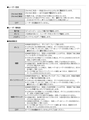
さらに、電子機器10は、報知対象物に関する情報の報知の内容およびタイミングに関し、さらに図46〜図48に示す表のとおり報知を行うようにしてもよい。 Further, the electronic device 10 may further notify the content and timing of the notification of the information regarding the notification target object as shown in the tables shown in FIGS. 46 to 48.

[7.電子機器10の機構]
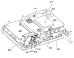
図49は、電子機器10の外観構成の一例を示す斜視図である。図50および図51は、電子機器10の外観構成の一例を示す六面図である。図50には、電子機器10の正面図、上面図、右側面図、底面図、および左側面図が示されている。図51には、電子機器10の背面図が示されている。この例では、電子機器10の筐体100は、正面側に位置する第1筐体1001と、後方側に位置する第2筐体1002とに分けられる。第1筐体1001の前面には、表示部13、発光部23およびセンサ部20の照度センサ201が設けられている。第1筐体1001の前面の開口部に表示部13の表示領域が位置する。第2筐体1002の上端面から音声を出力するように、スピーカ14が設けられている。筐体100の右側端面には、SDカードを装着するための装着部21(すなわち、SDカードスロット)が設けられている。筐体100の背面の右上方部には、受光部12が設けられている。また、筐体100の背面の左下部には、電源部22の電源スイッチ221およびDCジャック222が設けられている。
[7. Mechanism of electronic device 10]
FIG. 49 is a perspective view showing an example of the external configuration of the electronic device 10. 50 and 51 are six views showing an example of the external configuration of the electronic device 10. FIG. 50 shows a front view, a top view, a right side view, a bottom view, and a left side view of the electronic device 10. FIG. 51 shows a rear view of the electronic device 10. In this example, the housing 100 of the electronic device 10 is divided into a first housing 1001 located on the front side and a second housing 1002 located on the rear side. An illuminance sensor 201 of a display unit 13, a light emitting unit 23, and a sensor unit 20 is provided on the front surface of the first housing 1001. The display area of the display unit 13 is located in the opening on the front surface of the first housing 1001. The speaker 14 is provided so as to output sound from the upper end surface of the second housing 1002. A mounting portion 21 (that is, an SD card slot) for mounting an SD card is provided on the right end surface of the housing 100. A light receiving portion 12 is provided on the upper right portion of the back surface of the housing 100. Further, a power switch 221 and a DC jack 222 of the power supply unit 22 are provided in the lower left portion of the back surface of the housing 100.

図51に示すように、第2筐体1002の背面には、蓋部1003が設けられている。蓋部1003は、背面から見て第2筐体1002の右上寄りの位置に設けられている。蓋部1003は、第2筐体1002に着脱可能な蓋であり、上下方向よりも左右方向に長い部材である。蓋部1003は、少なくともパルス光Loutを透過させる素材により形成される光透過部である。蓋部1003は、筐体100と同じ素材で形成されるとよいが、異なる素材で形成されてもよい。蓋部1003は、樹脂またはその他の素材で形成される。蓋部1003は、可視光を遮断する素材で形成され、可視光カットフィルタとしても機能するとよいが、そうでなくてもよい。蓋部1003は、半透明または透明の部材としてもよい。また、蓋部1003に代えて、筐体100の背面に、少なくともパルス光Loutを透過させる部分である光透過部が形成されてもよい。 As shown in FIG. 51, a lid portion 1003 is provided on the back surface of the second housing 1002. The lid portion 1003 is provided at a position closer to the upper right of the second housing 1002 when viewed from the back surface. The lid portion 1003 is a lid that can be attached to and detached from the second housing 1002, and is a member that is longer in the left-right direction than in the up-down direction. The lid portion 1003 is a light transmitting portion formed of at least a material that transmits pulsed light Lout. The lid portion 1003 may be formed of the same material as the housing 100, but may be formed of a different material. The lid 1003 is made of resin or other material. The lid portion 1003 is formed of a material that blocks visible light, and may or may not function as a visible light cut filter. The lid portion 1003 may be a translucent or transparent member. Further, instead of the lid portion 1003, a light transmitting portion which is a portion through which at least the pulsed light Lout is transmitted may be formed on the back surface of the housing 100.

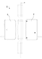
図52は、第2筐体1002から蓋部1003を取り外した様子を示す背面図である。図52に示すように、第2筐体1002には、第1窓101および第2窓102が形成されている。第1窓101および第2窓102は、外部の光を筐体100の内部に導くための開口部である。ただし、第1窓101および第2窓102は、少なくとも特定波長の光を透過させるレンズなどの部材を有してもよい。第1窓101と、第2窓102とは、左右方向において所定の間隔を空けて配置されている。第1窓101および第2窓102は、円形であるが、これ以外の形状であってもよい。筐体100の内部には、第1窓101および第2窓102を介してパルス光が入射する。蓋部1003が半透明または透明の部材である場合、第1窓101および第2窓102をユーザが視認可能である。これが意匠的な魅力を発揮する場合もある。 FIG. 52 is a rear view showing a state in which the lid portion 1003 is removed from the second housing 1002. As shown in FIG. 52, the first window 101 and the second window 102 are formed in the second housing 1002. The first window 101 and the second window 102 are openings for guiding external light to the inside of the housing 100. However, the first window 101 and the second window 102 may have a member such as a lens that transmits light of at least a specific wavelength. The first window 101 and the second window 102 are arranged at predetermined intervals in the left-right direction. The first window 101 and the second window 102 are circular, but may have other shapes. Pulsed light is incident inside the housing 100 through the first window 101 and the second window 102. When the lid portion 1003 is a translucent or transparent member, the user can visually recognize the first window 101 and the second window 102. In some cases, this has a design appeal.

図53は、電子機器10の分解斜視図である。図53(a),(b)に示すように、電子機器10の筐体100の内部には、第1筐体1001側から順に、表示部13、第1基板1010、および第2基板1030が収容されている。第1基板1010は、平面視において上下方向よりも左右方向に長い長方形上の基板である。第1基板1010の正面側の第1面には、表示部13が実装される。第1基板1010の当該第1面には、制御回路1331が実装されている。制御回路1331は、制御部11の機能の一部または全部を実現するようにするとよい。制御回路1331は、例えば集積回路(IC)とするとよい。制御回路1331は、ここでは1つとしているが、2以上の制御回路に置き換えられてもよい。第1基板1010の第1面とは反対側の第2面には、マイクロ波受信部15が実装されている。マイクロ波受信部15は、ほぼ直方体形状である。これらの部材を収容して、第2筐体1002は第1筐体1001にネジ止めされている。 FIG. 53 is an exploded perspective view of the electronic device 10. As shown in FIGS. 53 (a) and 53 (b), inside the housing 100 of the electronic device 10, the display unit 13, the first board 1010, and the second board 1030 are arranged in this order from the first housing 1001 side. It is contained. The first substrate 1010 is a rectangular substrate that is longer in the horizontal direction than in the vertical direction in a plan view. The display unit 13 is mounted on the first surface on the front side of the first substrate 1010. A control circuit 1331 is mounted on the first surface of the first substrate 1010. The control circuit 1331 may realize a part or all of the functions of the control unit 11. The control circuit 1331 may be, for example, an integrated circuit (IC). Although the number of control circuits 1331 is one here, it may be replaced with two or more control circuits. The microwave receiving unit 15 is mounted on the second surface of the first substrate 1010 opposite to the first surface. The microwave receiving unit 15 has a substantially rectangular parallelepiped shape. Accommodating these members, the second housing 1002 is screwed to the first housing 1001.

図54は、電子機器10からさらに第2筐体1002を取り外した状態を示す背面図である。図55、図56および図57は、この状態の電子機器10の内部構成を示す斜視図である。第2基板1030は、第1基板1010の背面側において、第1基板1010に重なるようにして配置されている。第2基板1030は、平面視においてほぼL字状の基板である。第2基板1030は、マイクロ波受信部15が存在する領域が切り欠かれているため、このような形状になっている。このようにすれば、マイクロ波受信部15に第2基板130が重なり合う場合に比べて、電子機器10の厚みの増大を抑えることができる。第2基板1030のうち、上下方向に長い第1領域Ar3には、受光部12が実装されている。第1窓101に面して、第1波長選択部121、および第1受光素子122が設けられている。第2窓102に面して、第2波長選択部123、および第2受光素子124が設けられている。 FIG. 54 is a rear view showing a state in which the second housing 1002 is further removed from the electronic device 10. 55, 56 and 57 are perspective views showing the internal configuration of the electronic device 10 in this state. The second substrate 1030 is arranged on the back side of the first substrate 1010 so as to overlap the first substrate 1010. The second substrate 1030 is a substantially L-shaped substrate in a plan view. The second substrate 1030 has such a shape because the region where the microwave receiving unit 15 exists is cut out. In this way, it is possible to suppress an increase in the thickness of the electronic device 10 as compared with the case where the second substrate 130 overlaps the microwave receiving unit 15. The light receiving portion 12 is mounted on the first region Ar3 which is long in the vertical direction in the second substrate 1030. A first wavelength selection unit 121 and a first light receiving element 122 are provided facing the first window 101. A second wavelength selection unit 123 and a second light receiving element 124 are provided facing the second window 102.

第1波長選択部121、および第1受光素子122、並びに第2窓102に面して、第2波長選択部123、および第2受光素子124は、シールドケース1031に収容されている。シールドケース1031は、例えば導電性の素材(例えば金属)で形成され、受光部12の素子が外部からの電磁波を影響としたノイズを発生しないようにするための部材である。電磁波の発生源は、車両40に設けられたワイパーを駆動する駆動部などの電気的な部品である。シールドケース1031は、第1受光素子122が収容される空間と、第2受光素子124が収容される空間とを隔てるための隔壁を有する。この隔壁はパルス光の伝搬も妨ぐ。このようにすれば、導電性を有する材料でシールドされていない場合に比べて、第1受光素子122および第2受光素子124が出力する信号が電磁的なノイズの影響を受けにくくなる。また、隔壁の存在により、第1波長選択部121を透過した光が第2受光素子124に受光され、かつ第2波長選択部123を透過した光が第1受光素子122に受光される可能性が低くなる。 The second wavelength selection unit 123 and the second light receiving element 124 are housed in the shield case 1031 facing the first wavelength selection unit 121, the first light receiving element 122, and the second window 102. The shield case 1031 is made of, for example, a conductive material (for example, metal), and is a member for preventing the element of the light receiving unit 12 from generating noise affected by electromagnetic waves from the outside. The source of electromagnetic waves is an electrical component such as a drive unit that drives a wiper provided in the vehicle 40. The shield case 1031 has a partition wall for separating the space in which the first light receiving element 122 is housed and the space in which the second light receiving element 124 is housed. This partition also prevents the propagation of pulsed light. In this way, the signals output by the first light receiving element 122 and the second light receiving element 124 are less likely to be affected by electromagnetic noise, as compared with the case where they are not shielded by the conductive material. Further, due to the presence of the partition wall, there is a possibility that the light transmitted through the first wavelength selection unit 121 is received by the second light receiving element 124 and the light transmitted through the second wavelength selection unit 123 is received by the first light receiving element 122. Will be low.

第2基板1030のうち、第2領域Ar4には、GPS受信部16およびスピーカ14が実装されている。第2領域Ar4は、第1領域Ar3よりも上下方向に短くかつ第1領域Ar3よりも上方に突出する。GPS受信部16のうち、正面側の第1面にGPSモジュールが実装され、背面側の第2面にGPSアンテナが実装されるようにするとよい。GPSアンテナについては上方に指向性を確保するため、マイクロ波受信部15よりも上方に配置されている。また、GPS受信部16のスペースを確保するため、第2基板1030における第2領域Ar4は、第1領域Ar3よりも上方に突出している。マイクロ波受信部15は、GPS受信部16およびスピーカ14の下方に位置する。装着部21が、第1基板1010の左方に実装されている。装着部21の下方には、電源部22の電源スイッチ221、DCジャック222およびボタン電池223が設けられている。ボタン電池223は、電子機器10の内部電源である。また、第2基板1030の正面側であって、第1領域Ar3の反対側には、通信部17の無線モジュール171が実装されている。 A GPS receiving unit 16 and a speaker 14 are mounted on the second region Ar4 of the second substrate 1030. The second region Ar4 is shorter in the vertical direction than the first region Ar3 and projects upward from the first region Ar3. Among the GPS receiving units 16, the GPS module may be mounted on the first surface on the front side, and the GPS antenna may be mounted on the second surface on the back side. The GPS antenna is arranged above the microwave receiving unit 15 in order to secure the directivity upward. Further, in order to secure a space for the GPS receiving unit 16, the second region Ar4 on the second substrate 1030 projects upward from the first region Ar3. The microwave receiving unit 15 is located below the GPS receiving unit 16 and the speaker 14. The mounting portion 21 is mounted on the left side of the first substrate 1010. Below the mounting unit 21, a power switch 221 of the power supply unit 22, a DC jack 222, and a button battery 223 are provided. The button battery 223 is an internal power source for the electronic device 10. Further, the wireless module 171 of the communication unit 17 is mounted on the front side of the second substrate 1030 and on the opposite side of the first region Ar3.

図58は、第2基板1030の写真を示す。図58(a)は背面側から見た図、図58(b)は正面側から見た図である。図58(a)で「(16)」と示した領域にGPS受信部16が実装され、「(14)」と示した領域にスピーカ14が実装される。また、第2基板1030の白線で囲んだ領域に受光部12が実装される。図59は、受光部12の電気的な構成である。第1受光素子122は、ここではフォトダイオードPD1である。フォトダイオードPD1には、第1波長選択部121を介した光が受光面に入射する。PD1のカソードは高電位側の電源ラインと接続され、アノードは抵抗R1の一端と接続する。抵抗R1の他端は接地されている。アンプIC1(1/2)の入力端は、フォトダイオードPD1のアノードと抵抗R1の一端とに共通に接続されている。アンプIC1(1/2)の出力端は、差動増幅器AMPの負極側の入力端子に接続されている。第2受光素子124は、ここではフォトダイオードPD2である。フォトダイオードPD2には、第2波長選択部123を介した光が受光面に入射する。フォトダイオードPD2のカソードは高電位側の電源ラインと接続され、アノードは抵抗R2の一端と接続する。抵抗R2の他端は接地されている。アンプIC1(2/2)の入力端は、フォトダイオードPD2のアノードと抵抗R2の一端とに共通に接続されている。アンプIC1(2/2)の出力端は、差動増幅器AMPの正極側の入力端子に接続されている。アンプIC1(1/2)およびアンプIC1(2/2)は、出力を1/2にして出力する。差動増幅器AMPの出力端からは、フォトダイオードPD1,PD2の受光量の差分に応じた信号が出力される。制御部11は、この差分に基づいて速度測定装置30を検出する。制御部11は、差動増幅器AMPにより増幅され、さらに、アンプQ1およびアンプIC2(2/2)を経た後、波形成形後の信号に基づいて、速度測定装置30を検出するとよい。 FIG. 58 shows a photograph of the second substrate 1030. FIG. 58 (a) is a view seen from the back side, and FIG. 58 (b) is a view seen from the front side. The GPS receiving unit 16 is mounted in the area indicated by “(16)” in FIG. 58 (a), and the speaker 14 is mounted in the area indicated by “(14)”. Further, the light receiving portion 12 is mounted in the region surrounded by the white line of the second substrate 1030. FIG. 59 shows the electrical configuration of the light receiving unit 12. The first light receiving element 122 is a photodiode PD1 here. Light passing through the first wavelength selection unit 121 is incident on the light receiving surface of the photodiode PD1. The cathode of PD1 is connected to the power supply line on the high potential side, and the anode is connected to one end of the resistor R1. The other end of the resistor R1 is grounded. The input end of the amplifier IC1 (1/2) is commonly connected to the anode of the photodiode PD1 and one end of the resistor R1. The output end of the amplifier IC1 (1/2) is connected to the input terminal on the negative electrode side of the differential amplifier AMP. The second light receiving element 124 is a photodiode PD2 here. Light passing through the second wavelength selection unit 123 is incident on the light receiving surface of the photodiode PD2. The cathode of the photodiode PD2 is connected to the power supply line on the high potential side, and the anode is connected to one end of the resistor R2. The other end of the resistor R2 is grounded. The input end of the amplifier IC1 (2/2) is commonly connected to the anode of the photodiode PD2 and one end of the resistor R2. The output end of the amplifier IC1 (2/2) is connected to the input terminal on the positive electrode side of the differential amplifier AMP. The amplifier IC1 (1/2) and the amplifier IC1 (2/2) halve the output and output. From the output end of the differential amplifier AMP, a signal corresponding to the difference in the amount of light received by the photodiodes PD1 and PD2 is output. The control unit 11 detects the speed measuring device 30 based on this difference. The control unit 11 may detect the speed measuring device 30 based on the signal after waveform shaping after being amplified by the differential amplifier AMP and further passing through the amplifier Q1 and the amplifier IC2 (2/2).

図60は、第1波長選択部121および第2波長選択部123のフィルタ特性の一例を示グラフである。第1波長選択部121は、ここでは、バンド・パス・フィルタである。図60(a)に示すように、目的波長である特定波長λout905nmを含む波長領域の光を透過させ、それ以外の波長領域の光を遮断する。光が透過する波長領域の幅は、例えば20nmであるが、これよりも狭いことがより望ましい。第2波長選択部123は、例えば、バンド・エリミネーション・フィルタである。図60(b)に示すように、第2波長選択部123は、特定波長λoutを含む波長領域の光を遮断し、非目的波長であるそれ以外の波長領域の光を透過させる。光が遮断される波長領域の幅は、例えば20nmであるが、これよりも狭いことがより望ましい。 FIG. 60 is a graph showing an example of the filter characteristics of the first wavelength selection unit 121 and the second wavelength selection unit 123. The first wavelength selection unit 121 is a bandpass filter here. As shown in FIG. 60A, light in a wavelength region including a specific wavelength λout905 nm, which is a target wavelength, is transmitted, and light in other wavelength regions is blocked. The width of the wavelength region through which light is transmitted is, for example, 20 nm, but it is more desirable that the width is narrower than this. The second wavelength selection unit 123 is, for example, a band elimination filter. As shown in FIG. 60B, the second wavelength selection unit 123 blocks light in a wavelength region including a specific wavelength λout and transmits light in a wavelength region other than the non-target wavelength. The width of the wavelength region where light is blocked is, for example, 20 nm, but it is more desirable that the width is narrower than this.

図60においては、光が透過する周波数領域の透過率を80%よりも大きく、遮断する周波数領域を15%未満としているが、それぞれ実用上耐えうる透過率であればよい。波長選択部は、図60で例示されるような急峻な特性を示すことが望ましいが、よりブロードな特性を示してもよい。 In FIG. 60, the transmittance of the frequency region through which light is transmitted is larger than 80%, and the frequency region at which light is blocked is less than 15%. However, the transmittance may be practically acceptable. The wavelength selection unit preferably exhibits steep characteristics as illustrated in FIG. 60, but may exhibit broader characteristics.

電子機器10からさらに第2基板1030を取り外すと、図61に示す状態となる。 When the second substrate 1030 is further removed from the electronic device 10, the state shown in FIG. 61 is obtained.

[8.電子機器の他の例]
図62は、電子機器の他の例である電子機器80の外観構成を示す斜視図である。図63は、電子機器80を車両の進行方向に対して右斜め前方側からみたときの外観構成を示す斜視図である。図62および図63に示すように、電子機器80はほぼ直方体形状の箱型の装置である。電子機器80は、表示部13を有しておらず、外部機器に有線のケーブル81を介して各種信号を出力する。電子機器80は、無線の通信路を介して外部機器と通信してもよい。電子機器80は、上方に位置する第1筐体801と下方に位置する第2筐体802とに分けられる。電子機器80の前方側には、蓋部803が設けられている。蓋部803は、蓋部1003と同様、パルス光を透過させる素材で形成されている光透過部材である。
[8. Other examples of electronic devices]
FIG. 62 is a perspective view showing an external configuration of the electronic device 80, which is another example of the electronic device. FIG. 63 is a perspective view showing the appearance configuration of the electronic device 80 when viewed from the diagonally right front side with respect to the traveling direction of the vehicle. As shown in FIGS. 62 and 63, the electronic device 80 is a box-shaped device having a substantially rectangular parallelepiped shape. The electronic device 80 does not have a display unit 13 and outputs various signals to an external device via a wired cable 81. The electronic device 80 may communicate with an external device via a wireless communication path. The electronic device 80 is divided into a first housing 801 located above and a second housing 802 located below. A lid 803 is provided on the front side of the electronic device 80. Like the lid 1003, the lid 803 is a light transmitting member made of a material that transmits pulsed light.

図64、図65および図66は、電子機器80の内部の構成を示す斜視図である。図63〜65に示すように、電子機器80の内部にあっては、第1基板810、第2基板820および第3基板830が下から上に向かって、互いに距離を空けて配置されている。ボタン電池811は、第1基板810に設けられ、電子機器80の内部電源である。従来の電子機器と異なる点は、受光部841が車両の進行方向前方側からのパルス光を受光するように第4基板840に形成され、かつそれに隣り合ってマイクロ波受信部のうちのアンテナ部850が配置されている点である。受光部841は、受光部12と同じ構成でよく、第4基板840と電気的に接続される。第4基板840は、第1基板810と図示せぬ端子を介して電気的に接続されている。アンテナ部850は、マイクロ波受信部のうちのアンテナとして機能する部分である。アンテナ部850は、基板上に形成された所定のパターンにより構成される。マイクロ波受信部のうちのアンテナ部850からの信号を処理する処理回路851は、第2基板820上に実装されている。第3基板830の上方には、GPS受信部860が実装されている。このような構成の下、電子機器80は、音や表示を利用した報知を、ケーブル81を介して外部に接続された出力先(例えば、従来型のレーザー探知機)に出力して情報の報知を行わせる報知制御を行う。この報知に関わる機能は、電子機器10と同じでよい。アンテナ部850は、第4基板840に隣り合う位置に配置されている。アンテナ部850の法線方向と第4基板840の法線方向とが交差するようにするとよいが、特に平行にするとよい。 64, 65 and 66 are perspective views showing the internal configuration of the electronic device 80. As shown in FIGS. 63 to 65, inside the electronic device 80, the first substrate 810, the second substrate 820, and the third substrate 830 are arranged at a distance from each other from the bottom to the top. .. The button battery 811 is provided on the first substrate 810 and is an internal power source for the electronic device 80. The difference from the conventional electronic device is that the light receiving unit 841 is formed on the fourth substrate 840 so as to receive the pulsed light from the front side in the traveling direction of the vehicle, and the antenna unit of the microwave receiving unit is adjacent to the light receiving unit 841. This is the point where the 850 is arranged. The light receiving unit 841 may have the same configuration as the light receiving unit 12, and is electrically connected to the fourth substrate 840. The fourth substrate 840 is electrically connected to the first substrate 810 via a terminal (not shown). The antenna unit 850 is a portion of the microwave receiving unit that functions as an antenna. The antenna portion 850 is composed of a predetermined pattern formed on the substrate. The processing circuit 851 that processes the signal from the antenna unit 850 of the microwave receiving unit is mounted on the second substrate 820. A GPS receiving unit 860 is mounted above the third substrate 830. Under such a configuration, the electronic device 80 outputs a notification using sound or display to an output destination (for example, a conventional laser detector) connected to the outside via a cable 81 to notify the information. Performs notification control. The function related to this notification may be the same as that of the electronic device 10. The antenna portion 850 is arranged at a position adjacent to the fourth substrate 840. It is preferable that the normal direction of the antenna portion 850 and the normal direction of the fourth substrate 840 intersect, but it is particularly preferable that they are parallel.

このようにすれば、既存のシステムからの変更点を少なくしつつ、速度測定装置の存在をユーザに報知するための技術を提供することができる。 In this way, it is possible to provide a technique for notifying the user of the existence of the speed measuring device while reducing the changes from the existing system.

[9.ノイズ低減方法]
ノイズの発生源が受光部12の回路自体である場合、アンプのゲインを下げてノイズフロアを低くする方法が有効である。これに対し、受光部におけるC/N比を改善すれば、アンプのゲインを上げることができ、望ましい。ノイズはアンプ回路自体から出ることがあり、これはランダムノイズである。アンプ回路は、フォトダイオードよりも回路部の部分をいう。そこで、ノイズを抑えるため、受光部12の出力を2組のアンプ回路(アンプ回路1およびアンプ回路2)に入れた構成を採用するとよい。この例において、図67に示すように、アンプ回路1の閾値Thを超えるノイズピークをピークN1、パルス光を受光したときの信号のピークをピークP1、アンプ回路2の閾値Thを超えるノイズピークをピークN2、パルス光を受光したときの信号をピークP2とすると、N1とN2が時間的に一致する確率は非常に低く、P1とP2は一致する。そこで、N1とN2の両方を同時に検出した場合にパルス光の受光とみななせば、ノイズの低減が軽減され、検出精度が改善すると考えられる。図67に示すように、(P1+P2)/2とすることにより2つの回路の閾値を越えるピーク値がずれていれば、足して2で割ることにより、ピーク値を下げることができる。このようなピーク値のずれの有無を判断するため、コンパレータが用いられてもよい。
[9. Noise reduction method]
When the noise source is the circuit itself of the light receiving unit 12, it is effective to lower the gain of the amplifier to lower the noise floor. On the other hand, if the C / N ratio in the light receiving portion is improved, the gain of the amplifier can be increased, which is desirable. The noise can come from the amplifier circuit itself, which is random noise. The amplifier circuit refers to the circuit part rather than the photodiode. Therefore, in order to suppress noise, it is preferable to adopt a configuration in which the output of the light receiving unit 12 is inserted into two sets of amplifier circuits (amplifier circuit 1 and amplifier circuit 2). In this example, as shown in FIG. 67, the noise peak exceeding the threshold Th of the amplifier circuit 1 is the peak N1, the peak of the signal when receiving the pulsed light is the peak P1, and the noise peak exceeding the threshold Th of the amplifier circuit 2 is the peak N1. Assuming that the peak N2 and the signal when the pulsed light is received are the peak P2, the probability that N1 and N2 match in time is very low, and P1 and P2 match. Therefore, if both N1 and N2 are detected at the same time and regarded as light reception of pulsed light, it is considered that the reduction of noise is reduced and the detection accuracy is improved. As shown in FIG. 67, if the peak values exceeding the thresholds of the two circuits deviate by setting (P1 + P2) / 2, the peak value can be lowered by adding and dividing by 2. A comparator may be used to determine the presence or absence of such a deviation of the peak value.

この実施形態では、アンプQ1がノイズの発生源であるため、アンプQ1を、回路その1のアンプと回路その2のアンプとこれらの出力を1/2にする回路に置き換得る構成とするとよい。また、受光部12の回路に積分回路を設けてもよい。また、回路その1をコンデンサ等を用いた積分回路で積分して、回路その2はそのままとし、コンパレータを設けてもよい。 In this embodiment, since the amplifier Q1 is the source of noise, it is preferable that the amplifier Q1 can be replaced with the amplifier of the circuit 1 and the amplifier of the circuit 2 and a circuit that halves their outputs. .. Further, an integrating circuit may be provided in the circuit of the light receiving unit 12. Further, the circuit 1 may be integrated by an integrator circuit using a capacitor or the like, the circuit 2 may be left as it is, and a comparator may be provided.

[10.他の実施形態]
(10−1)電子機器10は、警察官がいるように見える反射材のパターンを検出した場合に警報を発するシステムとしてもよい。反射材のパターンは、警察官がいるような所定地点に配置される反射材のパターンである。このパターンは、所定の看板または警察官の衣装に用いられるパターンとするとよい。電子機器10は、車載カメラ50を用いて、車両40の前方を撮像した画像を取得してこれを解析し、所定の反射材パターンの存在を検出するとよい。このようにすれば、警察官がいる可能性が高い場所においてその存在を報知することができ、誤報知の可能性を低くすることができる。警報は、表示、音またはこれらの組み合わせにより行われるとよい。
[10. Other embodiments]
(10-1) The electronic device 10 may be a system that issues an alarm when it detects a pattern of a reflective material that appears to have a police officer. The reflector pattern is a reflector pattern that is placed at a predetermined point where a police officer is present. This pattern may be the pattern used for a given signboard or the costume of a police officer. The electronic device 10 may use the vehicle-mounted camera 50 to acquire an image of the front of the vehicle 40 and analyze it to detect the presence of a predetermined reflector pattern. In this way, it is possible to notify the presence of a police officer in a place where there is a high possibility of being present, and it is possible to reduce the possibility of false alarm. The alarm may be given by display, sound or a combination thereof.

(10−2)(10−1)において、前記警報は速度取締警報であることとするとよい。速度取締警報は、速度取締地点に接近している旨の警報であるとよい。 In (10-2) and (10-1), the alarm may be a speed control alarm. The speed control warning may be a warning that the speed control point is approaching.

(10−3)検出対象の前記警察官がいるように見える反射材のパターンとして、人の腰の位置に相当する横方向の線と、警棒に相当する縦方向の線と、ヘルメットの水平位置に相当する線と、タスキに相当する線と、ベストのV字に相当する線のうち少なくとも2つ以上を含むパターンとするとよい。例えば特に上から斜め・横・縦の順にラインが検出されたこととするとよい。 (10-3) As a pattern of the reflective material that makes it appear that the police officer to be detected is present, a horizontal line corresponding to the position of a person's waist, a vertical line corresponding to a baton, and a horizontal position of a helmet. It is preferable that the pattern includes at least two or more of the line corresponding to the line, the line corresponding to the baton, and the line corresponding to the best V shape. For example, it is preferable that the lines are detected in the order of diagonal, horizontal, and vertical from the top.

(10−4)電子機器10は、前記警察官がいるように見える反射材のパターンを検出は、再帰反射テープに相当する反射レベルの検出に基づいて行うこととするとよい。 (10-4) The electronic device 10 may detect the pattern of the reflective material in which the police officer appears to be present, based on the detection of the reflection level corresponding to the retroreflective tape.

(10−5)電子機器10は、人の高さより高い位置では前記警察官がいるように見える反射材のパターンとしての検出を抑制するようにするとよい。抑制方法として、予め一定高さ以上の部分は検出しないようにするとよい。また、当該パターンを検出しても一定高さ以上なら検出としないようにするとよい。また、縦方向の人の高さ(例えば、2m以内など)にすべての反射材のパターンの構成要素が含まれていることも条件とするとよい。 (10-5) The electronic device 10 may suppress the detection as a pattern of the reflective material in which the police officer appears to be present at a position higher than the height of a person. As a suppressing method, it is advisable not to detect a portion having a certain height or higher in advance. Further, even if the pattern is detected, if it is above a certain height, it may not be detected. It is also preferable that the height of the person in the vertical direction (for example, within 2 m) includes all the components of the reflector pattern.

(10−5)において、電子機器10は、路面に相当する位置も排除して、路面の停止線などを誤認することも防止するとよい。路面の停止線は縦横の線からなり再帰反射と同様の光量となるケースがあるので排除する。 In (10-5), it is preferable that the electronic device 10 also excludes the position corresponding to the road surface to prevent the stop line of the road surface from being mistakenly recognized. The stop line on the road surface consists of vertical and horizontal lines, and in some cases the amount of light is the same as that of retroreflection, so it is excluded.

(10−6)電子機器10は、前記警察官がいるように見える反射材のパターンが予め設置されている場所の位置情報を記憶しておき、その記憶された位置では、前記警報を抑制するようにするとよい。 (10-6) The electronic device 10 stores the position information of the place where the pattern of the reflective material that looks like the police officer is installed in advance, and suppresses the alarm at the stored position. It is good to do so.

(10−7)電子機器10は、前記警察官がいるように見える反射材のパターンの検出個数に応じて前記警報の態様を変更することとするとよい。例えば前記警察官がいるように見える反射材のパターンを1つ検出したときは、前記警報としての取締警報は行わず、前記警察官がいるように見える反射材のパターンを複数検出したときは、前記警報として取締警報を行うようにするとよい。 (10-7) The electronic device 10 may change the mode of the alarm according to the number of detected patterns of the reflective material in which the police officer appears to be present. For example, when one pattern of the reflective material appearing to have the police officer is detected, the crackdown warning as the alarm is not issued, and when a plurality of patterns of the reflective material appearing to have the police officer are detected, the control alarm is not issued. It is advisable to issue a crackdown alarm as the alarm.

(10−8)電子機器10は、前記警察官がいるように見える反射材のパターンが所定時間内に1つしか検出されないときは前記警報を抑制するようにするとよい。電子機器10は、所定時間のウィンドウ内の検出個数で警報するか決めるとよい。所定時間は2秒程度とするとよい。 (10-8) The electronic device 10 may suppress the alarm when only one pattern of the reflective material appearing to have the police officer is detected within a predetermined time. The electronic device 10 may decide whether to give an alarm based on the number of detections in the window at a predetermined time. The predetermined time is preferably about 2 seconds.

(10−9)電子機器10は、前記警察官がいるように見える反射材のパターンの検出はドライブレコーダに備えたカメラによって撮像された映像信号に基づいて行うこととするとよい。パルス光の検出範囲より遠くから検出できる可能性がある。 (10-9) It is preferable that the electronic device 10 detects the pattern of the reflective material in which the police officer appears to be present based on the video signal captured by the camera provided in the drive recorder. It may be possible to detect from a distance beyond the detection range of pulsed light.

(10−10)電子機器10は、前記警察官がいるように見える反射材のパターンの検出は、後方については行わず、前方については追越車線については行わず、走行車線上より左側について行うこととするとよい。 (10-10) The electronic device 10 does not detect the pattern of the reflective material in which the police officer appears to be present, does not detect the pattern in the rear direction, does not detect the pattern in the overtaking lane in the front direction, and performs the detection in the left side of the traveling lane. It is good to say that.

(10−11)電子機器10は、道路を走行するための車両の速度を測定するのための電磁波(例えばパルス光またはマイクロ波)を検出した場合に警報をする機能を備え、前記警察官がいるように見える反射材のパターンを検出した場合であっても前記道路を走行するための車両の速度を測定するのための電磁波を検出した場合には、前記道路を走行するための車両の速度を測定するのための電磁波を検出した場合の警報を優先して行い、前記警察官がいるように見える反射材のパターンを検出した場合の警報は抑制することとするとよい。 (10-11) The electronic device 10 has a function of issuing an alarm when an electromagnetic wave (for example, pulsed light or microwave) for measuring the speed of a vehicle for traveling on a road is detected, and the police officer said. Even when the pattern of the reflective material that appears to be present is detected, when the electromagnetic wave for measuring the speed of the vehicle traveling on the road is detected, the speed of the vehicle traveling on the road is detected. It is advisable to give priority to an alarm when an electromagnetic wave for measuring is detected, and to suppress an alarm when a pattern of a reflective material that appears to have a police officer is detected.

(10−12)電子機器10は、道路を走行するための車両の速度を測定するのための電磁波を検出した場合に警報をする機能を備え、前記警察官がいるように見える反射材のパターンを検出するとともに、道路を走行するための車両の速度を測定するのための電磁波を検出した場合には、単独で検出した場合の警報とは異なる警報を行う(特に、より緊急度が高いことを示す警報を行う)とよい。 (10-12) The electronic device 10 has a function of giving an alarm when an electromagnetic wave for measuring the speed of a vehicle for traveling on a road is detected, and a pattern of a reflective material appearing to have the police officer. When an electromagnetic wave for measuring the speed of a vehicle for traveling on a road is detected, an alarm different from the alarm when it is detected alone is issued (especially, the urgency is higher). It is good to give an alarm indicating.

(10−13)電子機器10は、物の有無を検出するための赤外線検出装置を備え、警察官がいるように見える反射材のパターンの検出と合わせて、取り締まりの種別を判定(推測)する機能を備えてもよい。人物無しで、反射材ありの場合、オービスだけの可能性が高い。人物ありで、反射材ありの場合、オービスを含む多岐にわたる取り締まりの可能性が高い。制御部11は、このような種別の判定結果に基づいて、情報の報知をするとよい。報知として、表示および音声の一方または両方を異ならせるとよい。 (10-13) The electronic device 10 is provided with an infrared detection device for detecting the presence or absence of an object, and determines (guesses) the type of crackdown together with the detection of the pattern of the reflective material that appears to have a police officer. It may have a function. If there is no person and there is a reflector, there is a high possibility that it is only Orbis. If there is a person and there is a reflector, there is a high possibility of a wide range of crackdowns including Orbis. The control unit 11 may notify the information based on the determination result of such a type. As a notification, one or both of the display and the voice may be different.

(10−14)電子機器10は、ナイトポリスのパターンに合致する動くものを認識した場合、ナイトポリス看板ではなく、警察官であると判定するようにするとよい。制御部11は、自車挙動をキャンセルして算出する。 (10-14) When the electronic device 10 recognizes a moving object that matches the pattern of the night police, it may be determined that the electronic device 10 is not a night police sign but a police officer. The control unit 11 cancels the behavior of the own vehicle and calculates it.

(10−15)電子機器10は、昼間(ないし明るいとき)は、ナイトポリス警告を抑制する(例えば実行しない)機能を備えること。特にナイトポリス看板の認識処理すらしないようにするとよい。 (10-15) The electronic device 10 has a function of suppressing (for example, not executing) a night police warning during the daytime (or when it is bright). In particular, it is advisable not to even recognize the night police signboard.

[11.他の実施形態]
さらに、他の実施形態を説明する。[11.他の実施形態]の項には他の項で説明した事項と共通する思想に基づく構成が含まれる場合がある。
[11. Other embodiments]
Further, other embodiments will be described. [11. The section of [Other Embodiments] may include a structure based on the same idea as the matters described in the other sections.

電子機器10は、速度測定装置30からのパルス光の受光に用いられる部位が飛び出していてもよい。電子機器10は、例えば、受光部12の少なくとも一部が設けられる部位が、他の部位よりも突き出た形状を有してもよい。以下、かかる構成の具体的な実施の形態を説明する。 In the electronic device 10, the portion used for receiving the pulsed light from the speed measuring device 30 may protrude. The electronic device 10 may have, for example, a portion provided with at least a part of the light receiving portion 12 having a shape protruding from the other portions. Hereinafter, specific embodiments of such a configuration will be described.

(11−1)電子機器10は、筐体の背面または側面側から、車両の進行方向(例えば、表示部の表示画面の法線方向)における前方側に突出した位置に、光の入射部を有してもよい。入射部は、電子機器10のうち受光部に受光される光が入射する部位である。入射部は、電子機器10の外観に含まれる部位である。電子機器10は、例えば、上述した蓋部1003が設けられた部位は入射部であり、第1窓101または第2窓102が設けられた部位も入射部である。 (11-1) The electronic device 10 projects a light incident portion from the back surface or side surface side of the housing to a position protruding forward in the traveling direction of the vehicle (for example, the normal direction of the display screen of the display unit). You may have. The incident portion is a portion of the electronic device 10 where the light received by the light receiving portion is incident. The incident portion is a portion included in the appearance of the electronic device 10. In the electronic device 10, for example, the portion provided with the lid portion 1003 described above is the incident portion, and the portion provided with the first window 101 or the second window 102 is also the incident portion.

このようにすることで、より前方で受光できるので、レーザー光を遮る障害物の影響を受けづらくすることができる。特にフロントガラスを通過した光を受光する構成としたときフロントガラスによって屈折された速度測定装置30からの光の影響を、入射部がフロントガラスにより近く設置できることにより軽減できる。特に表示部と受光部を一体とした筐体としたときにこの構成を取ると、車室内への取り付けを簡便かつ容易にできるとともに、上述した影響を軽減できる。 By doing so, since the light can be received in the front, it is possible to make it less susceptible to the influence of obstacles that block the laser beam. In particular, when the structure is such that the light that has passed through the windshield is received, the influence of the light refracted by the windshield from the speed measuring device 30 can be reduced by allowing the incident portion to be installed closer to the windshield. In particular, if this configuration is adopted when the display unit and the light receiving unit are integrated into an integrated housing, it can be easily and easily installed in the vehicle interior, and the above-mentioned influence can be reduced.

図68(a)の例では、電子機器10の筐体100の背面1004には、第1部位10041と、第1部位1041よりも車両の進行方向における前方側に突出した第2部位1042とが設けられる。第1部位1041は平坦である。第2部位1032は、ここでは、半球面形状である。第2部位1042の一部または全部が入射部に相当する。 In the example of FIG. 68A, the back surface 1004 of the housing 100 of the electronic device 10 has a first portion 10041 and a second portion 1042 projecting forward from the first portion 1041 in the traveling direction of the vehicle. Provided. The first site 1041 is flat. The second portion 1032 has a hemispherical shape here. Part or all of the second portion 1042 corresponds to the incident portion.

第2部位1042は、例えば、背面1004の上下方向における中心よりも上方に位置するとよい。下方である場合に比べて、速度測定装置30からの光を遮る障害物による影響を受けにくくなる可能性がある。第2部位1042は、車両の進行方向における後方側(車室が存在する側とするとよい。)から見て、背面1004の左右方向における中心よりも右側に設けられている。または、第2部位1042は、車両の進行方向における後方側から見て、背面1004の左右方向における中心よりも左側に設けられてもよい。この場合に、速度測定装置30により近い、車両の進行方向における左側の位置に入射部が位置することになり、受光の観点から望ましい場合がある。 The second portion 1042 may be located, for example, above the center of the back surface 1004 in the vertical direction. Compared to the case where it is downward, it may be less affected by an obstacle that blocks the light from the speed measuring device 30. The second portion 1042 is provided on the right side of the center of the rear surface 1004 in the left-right direction when viewed from the rear side in the traveling direction of the vehicle (preferably the side where the vehicle interior exists). Alternatively, the second portion 1042 may be provided on the left side of the center of the back surface 1004 in the left-right direction when viewed from the rear side in the traveling direction of the vehicle. In this case, the incident portion is located at a position on the left side in the traveling direction of the vehicle, which is closer to the speed measuring device 30, which may be desirable from the viewpoint of light reception.

(11−2)電子機器10は、筐体の背面または側面側から、車両の進行方向に対して左方向(または表示部の表示画面と平行な方向)側に突出した位置に入射部を有してもよい。 (11-2) The electronic device 10 has an incident portion at a position protruding from the back surface or side surface side of the housing to the left side (or a direction parallel to the display screen of the display unit) with respect to the traveling direction of the vehicle. You may.

(11−3)電子機器10は、筐体の背面または側面側から、車両の進行方向の前方左方向(または、表示部13に表示画面の法線と交差する方向であって左方向)に突出した位置に入射部を有してもよい。この場合において、入射部は、斜め左方向を法線方向とする面を有するようにするとよい。 (11-3) The electronic device 10 is moved from the back surface or the side surface side of the housing in the front left direction (or the direction intersecting the normal line of the display screen on the display unit 13 and the left direction) in the traveling direction of the vehicle. The incident portion may be provided at a protruding position. In this case, the incident portion may have a surface whose normal direction is diagonally to the left.

図68(b)の例では、電子機器10の筐体の背面1004Aに、第1部位1041と、第1部位1041Aよりも車両の進行方向における前方左方向側に突出した第2部位10042Aとが設けられる。第2部位1042Aは、ここでは角柱状である。第2部位1005Bの先端側の面1043の一部または全部が入射部に相当する。面1043は、第1部位1041とは平行な面ではなく、車両の進行方向に対して斜め方向を向いている。この場合に、速度測定装置30により近い、車両の進行方向における左側の位置に入射部が位置することになり、受光の観点から望ましい場合がある。 In the example of FIG. 68B, on the back surface 1004A of the housing of the electronic device 10, a first portion 1041 and a second portion 10024A protruding forward and leftward in the traveling direction of the vehicle from the first portion 1041A are formed. Provided. The second site 1042A is here columnar. Part or all of the front end side surface 1043 of the second portion 1005B corresponds to the incident portion. The surface 1043 is not a surface parallel to the first portion 1041, but faces an oblique direction with respect to the traveling direction of the vehicle. In this case, the incident portion is located at a position on the left side in the traveling direction of the vehicle, which is closer to the speed measuring device 30, which may be desirable from the viewpoint of light reception.

面1043は、例えば平面とするとよいが、前方左方向を向く曲面の部分を含むようにしてもよい(例えば、曲面として円弧面か球面を備えるとよい)。背面1004Aにおいて第2部位1042Aが設けられる位置は、背面1004において第2部位1042が設けられる位置と同様、種々の変形が可能である。 The surface 1043 may be, for example, a flat surface, but may include a portion of a curved surface facing forward and left (for example, an arc surface or a spherical surface may be provided as the curved surface). The position where the second portion 1042A is provided on the back surface 1004A can be variously modified in the same manner as the position where the second portion 1042 is provided on the back surface 1004.

この構成の下、第2部位1042Aの内部に受光部12の少なくともいずれかの受光素子が設けられ、かつ面1043が向く方向に向けて配置されてもよい。 Under this configuration, at least one of the light receiving elements of the light receiving unit 12 may be provided inside the second portion 1042A, and may be arranged so that the surface 1043 faces.

(11−1)〜(11−3)の構成において、筐体の背面から突出する部分(例えば、第2部位1042,1042A)の突出方向の長さが、電子機器10の筐体の厚みよりも小さくてもよいし、または大きくてもよい。図69(a)の例では、電子機器10の筐体100の背面1004Bには、第1部位1041と、第1部位1041よりも車両の進行方向における前方側に突出した第2部位1042Bとが設けられる。第2部位1042Bの突出方向の長さは、筐体の厚みよりも小さい。図69(b)の例では、電子機器10の筐体100の背面1004Cには、第1部位1041と、第1部位1041よりも車両の進行方向における前方側に突出した第2部位1042Cとが設けられる。第2部位1042Dの突出方向の長さは、筐体の厚みよりも大きい。 In the configurations (11-1) to (11-3), the length of the protruding portion (for example, the second portion 1042, 1042A) protruding from the back surface of the housing is larger than the thickness of the housing of the electronic device 10. May be small or large. In the example of FIG. 69A, the back surface 1004B of the housing 100 of the electronic device 10 has a first portion 1041 and a second portion 1042B protruding forward from the first portion 1041 in the traveling direction of the vehicle. Provided. The length of the second portion 1042B in the protruding direction is smaller than the thickness of the housing. In the example of FIG. 69B, the back surface 1004C of the housing 100 of the electronic device 10 has a first portion 1041 and a second portion 1042C projecting forward from the first portion 1041 in the traveling direction of the vehicle. Provided. The length of the second portion 1042D in the protruding direction is larger than the thickness of the housing.

(11−1)〜(11−3)の構成において、筐体の背面から突出する部分は、直方体状、立方体状、円柱状またはその他の柱状とするとよい。また、この突出する部分の先端の面は、平面、第1部位1041の表面に対して傾斜する傾斜面、曲面またはその他の形状の面とするとよい。突出する部分について、少なくとも一部に、かまぼこ状、球面上、三角柱形状、レンズ状、プリズム状などとして、光路を変更させたり、集光性をもたせるようにするとよい。その光路変更先、集光先にセンサを設けるとよい。 In the configurations (11-1) to (11-3), the portion protruding from the back surface of the housing may be a rectangular parallelepiped shape, a cube shape, a columnar shape, or another columnar shape. Further, the surface at the tip of the protruding portion may be a flat surface, an inclined surface inclined with respect to the surface of the first portion 1041, a curved surface, or a surface having another shape. It is preferable that at least a part of the protruding portion has a semi-cylindrical shape, a spherical surface, a triangular prism shape, a lens shape, a prism shape, or the like so as to change the optical path or to provide light collecting property. It is advisable to provide a sensor at the optical path change destination and the light collection destination.

(11−4)入射部は、筐体100とは別体に設けられてもよい。入射部は、筐体100と物理的に接触する部位に設けられてもよいし、接触しない部位に設けられてもよい。例えば、入射部に入射した光が受光部に受光され、その受光に応じた信号が制御部11に供給される構成であればよい。このようにすれば、例えば表示部13の見やすさの観点から、筐体100の位置または姿勢の変化に制約がある場合であっても、速度測定装置30からの光を受光しやすいように、入射部の位置または姿勢を調整することができる。 (11-4) The incident portion may be provided separately from the housing 100. The incident portion may be provided at a portion that physically contacts the housing 100, or may be provided at a portion that does not contact the housing 100. For example, the light incident on the incident portion may be received by the light receiving unit, and the signal corresponding to the received light may be supplied to the control unit 11. In this way, for example, from the viewpoint of visibility of the display unit 13, even if there are restrictions on the change in the position or posture of the housing 100, the light from the speed measuring device 30 can be easily received. The position or orientation of the incident part can be adjusted.

電子機器は、上記「別体」からの受光に応じた信号を出力する配線を接続するコネクタを備え、制御部は、当該コネクタを介して入力された前記受光に応じた信号に基づき報知制御を行ってもよい。 The electronic device includes a connector for connecting a wiring that outputs a signal corresponding to the received light from the "separate body", and the control unit performs notification control based on the signal corresponding to the received light input via the connector. You may go.

(11−5)(11−4)の「別体」として、入射部は、車両に取り付ける取付部材に設けてもよい。この場合、取付部材は、(11−1)〜(11−3)の入射部の位置に設けられてもよい。この場合、取付部材は、接着、固定具またはその他の方法により筐体に設けられるとよい。 As a "separate body" of (11-5) and (11-4), the incident portion may be provided on a mounting member to be attached to the vehicle. In this case, the mounting member may be provided at the position of the incident portion of (11-1) to (11-3). In this case, the mounting member may be provided on the housing by gluing, fixtures or other means.

(11−6)(11−4)の「別体」として、ドライブレコーダとするとよい。 A drive recorder may be used as the "separate body" of (11-6) and (11-4).

(11−7)(11−4)の「別体」として、ドライブレコーダの取付部とするとよい。この取付部は、車両の所定の取付箇所にドライブレコーダを取り付けるための部位である。取付部は、例えば、ドライブレコーダに物理的に接続される部位で、例えば取付箇所に面接触する部位を含むとよい。取付部材は、例えば、車両のフロントガラスに取り付けるものであって、フロントガラスの取付面側に入射部を有する構成とするとよい。 As a "separate body" of (11-7) and (11-4), it is preferable to use a drive recorder mounting portion. This mounting portion is a portion for mounting the drive recorder at a predetermined mounting location of the vehicle. The mounting portion may include, for example, a portion physically connected to the drive recorder, for example, a portion that comes into surface contact with the mounting portion. The mounting member may be, for example, mounted on the windshield of a vehicle and may have an incident portion on the mounting surface side of the windshield.

(11−8)筐体に報知制御を行う機能が備えられる構成に限られず、筐体にドライブレコーダの機能が備えられてもよい。 (11-8) The configuration is not limited to the configuration in which the housing is provided with the function of performing notification control, and the housing may be provided with the function of a drive recorder.

(11−9)入射部は、筐体に対して着脱自在に構成されてもよい。例えば、筐体には、入射部を装着するための装着部が設けられてもよい。装着部は、入射部を固定するための固定部が設けられてもよい。 (11-9) The incident portion may be detachably configured with respect to the housing. For example, the housing may be provided with a mounting portion for mounting the incident portion. The mounting portion may be provided with a fixing portion for fixing the incident portion.

(11−10)筐体に対する入射部の向きを調整する調整手段が設けるようにするとよい。調整手段としては、ミラータイプのドライブレコーダのカメラの向き調整と同様の構造とするとよい。また、筐体にカメラを備え、カメラと入射部の向きを独立に調整可能な構造としてもよい。 (11-10) It is preferable to provide an adjusting means for adjusting the direction of the incident portion with respect to the housing. The adjustment means may have a structure similar to that of the camera orientation adjustment of a mirror type drive recorder. Further, the housing may be provided with a camera so that the orientations of the camera and the incident portion can be adjusted independently.

(11−11)電子機器10において制御部11は、速度測定装置30からの光が受光されたと判定した場合に、映像や各種センサの値をその前後に渡って記録すようにするとよい。制御部11は、車両が位置するエリアが、ゾーン30内などの所定のエリア内だったか否かの情報を合わせて記録するようにするとよい。 (11-11) In the electronic device 10, when the control unit 11 determines that the light from the speed measuring device 30 has been received, it is preferable that the image and the values of various sensors are recorded before and after the image. The control unit 11 may record information on whether or not the area where the vehicle is located is within a predetermined area such as the zone 30.

(11−12)電子機器10において制御部11は、速度測定装置30からの光が受光されたときの報知(例えば、警報)に関連する設定情報を、その位置情報等とともに合わせて記録するようにするとよい。 (11-12) In the electronic device 10, the control unit 11 records the setting information related to the notification (for example, an alarm) when the light from the speed measuring device 30 is received, together with the position information and the like. It is good to set it to.

(11−13)電子機器10が所定の電波(例えば、マイクロ波)を受信した場合に報知制御を実行する構成において、入射部はマイクロ波受信部15よりも、車両の進行方向における前方側に配置されるようにするとよい。ここにおいて、前方側に配置されるとは、入射部がマイクロ波受信部15よりも前方側に突き出た構成とするとよい。 (11-13) In a configuration in which the notification control is executed when the electronic device 10 receives a predetermined radio wave (for example, microwave), the incident portion is closer to the front side in the traveling direction of the vehicle than the microwave receiving portion 15. It is good to arrange it. Here, it is preferable that the incident portion is arranged on the front side so that the incident portion protrudes forward from the microwave receiving portion 15.

(11−14)電子機器10が、GPS受信部16から取得した位置情報があらかじめ決められた条件を満たす場合に、報知制御を実行する構成において、入射部はGPS受信部16よりも、車両の進行方向における前方側に配置されるようにするとよい。ここにおいて、前方側に配置されるとは、入射部がマイクロ波受信部15よりも前方側に突き出た構成とするとよい。ここにおいて、あらかじめ決められた条件が、GPS受信部16から取得した位置情報が示す現在位置と、記憶部18に記憶された位置情報が示す位置とが、所定の接近関係にあることをいうようにしてもよい。 (11-14) In a configuration in which the electronic device 10 executes notification control when the position information acquired from the GPS receiving unit 16 satisfies a predetermined condition, the incident unit is more of a vehicle than the GPS receiving unit 16. It is preferable to arrange it on the front side in the traveling direction. Here, it is preferable that the incident portion is arranged on the front side so that the incident portion protrudes forward from the microwave receiving portion 15. Here, a predetermined condition means that the current position indicated by the position information acquired from the GPS receiving unit 16 and the position indicated by the position information stored in the storage unit 18 have a predetermined close relationship. You may do it.

(11−15)電子機器10が発光部23その他発光部を備える構成において、入射部は、発光部が設けられる面とは反対側の面に備えるようにするとよい。発光部が筐体100の前面側に設けられる場合、発光部は背面側に設けられるとよい。 (11-15) In a configuration in which the electronic device 10 includes a light emitting unit 23 and other light emitting units, the incident portion may be provided on a surface opposite to the surface on which the light emitting unit is provided. When the light emitting portion is provided on the front side of the housing 100, the light emitting portion may be provided on the back side.

(11−16)第2窓102に相当する第2受光量を得るための光が入射する部位(以下「第2入射部」という。)は、入射部が設けられた突出する部位内に設けられるようにするとよい。この場合において、第2入射部は、入射部が設けられた突出する部位内に入射部の向きと同じ向きとして設けられるようにするとよい。第2入射部は、入射部が設けられた突出する部位内に、入射部の向きと異なる向きとして設けられるようにするとよい。 (11-16) The portion where the light for obtaining the second light receiving amount corresponding to the second window 102 is incident (hereinafter referred to as “second incident portion”) is provided in the protruding portion where the incident portion is provided. It is good to be able to. In this case, the second incident portion may be provided in the protruding portion where the incident portion is provided in the same direction as the direction of the incident portion. The second incident portion may be provided in a protruding portion where the incident portion is provided in a direction different from the direction of the incident portion.

(11−17)
第2入射部は、入射部が設けられた突出する部位とは異なる筐体の部分に備えられるようにするとよい。第2入射部は、入射部が設けられた突出する部位内に、入射部の向きと同じ向きとして設けられるようにするとよい。第2入射部は、入射部が設けられた突出する部位内に、入射部の向きと異なる向きとして設けられてもよい。
(11-17)
The second incident portion may be provided in a portion of the housing different from the protruding portion provided with the incident portion. The second incident portion may be provided in the protruding portion where the incident portion is provided in the same direction as the direction of the incident portion. The second incident portion may be provided in a protruding portion where the incident portion is provided in a direction different from the direction of the incident portion.

(11−18)
ゾーン30、一車線道路、学校、幼稚園または保育園の少なくともいずれか1つと所定の接近関係を有する場合において、電子機器10の制御部11は、パルス光が受光されたと判定した場合、速度測定装置30であるとする可能性をアップさせる、または誤警報源であるとする可能性をダウンさせるようにするとよい。なお、ゾーン30は区域内における車両の走行速度や通り抜けを抑制する目的で、時速30キロの速度規制が実施される区域のことである。
(11-18)
When the control unit 11 of the electronic device 10 determines that the pulsed light has been received in the case where it has a predetermined proximity relationship with at least one of the zone 30, the one-lane road, the school, the kindergarten or the nursery school, the speed measuring device 30 It is advisable to increase the possibility of being a false alarm source or decrease the possibility of being a false alarm source. The zone 30 is an area where speed regulation of 30 km / h is enforced for the purpose of suppressing the traveling speed and passing through of the vehicle in the area.

光学方式の速度測定装置は持ち運びできるものと、路側・路上等に固定されているものがあるが、持ち運びできるものは、こうした場所の中のどこかに不定期に持ち運ばれて設置され、測定されることが多いため、運転者にとってより注意が必要であるが、このようにすれば、こうした場所でより確実に報知を行うことができる。また仮にこのような場所で誤警報の可能性が高まったとしても、こうした場所は事故に特に注意すべき場所であるから、たとえ誤報の可能性が高まったとしても運転者にこうした場所での安全に対する意識付けをできることを発明者らは見出した。 Some optical speed measuring devices are portable and some are fixed on the roadside or on the road, but those that can be carried are irregularly carried and installed somewhere in these places for measurement. It is necessary for the driver to be more careful because it is often done, but in this way, the notification can be performed more reliably in such a place. Also, even if the possibility of false alarms increases in such places, since these places are places where special attention should be paid to accidents, even if the possibility of false alarms increases, the driver is safe in these places. The inventors have found that they can raise awareness of.

(11−19)電子機器10の制御部11は、深夜などの所定の時間帯、悪天候などの所定の天候、複数車線などの所定の道路の走行中の少なくともいずれか1つであることを判定した場合、速度測定装置30であるとする可能性をアップさせる、または誤警報源であるとする可能性をダウンさせるようにするとよい。 (11-19) The control unit 11 of the electronic device 10 determines that it is at least one of a predetermined time zone such as midnight, a predetermined weather such as bad weather, and a predetermined road such as a plurality of lanes. If this is the case, it is preferable to increase the possibility that the speed measuring device 30 is used, or reduce the possibility that the speed measuring device 30 is a false alarm source.

持ち運びできるタイプのものは、こうした状況では、誤測定の可能性が高まるなどのため、測定を行わないことが多いことを発明者らは見出した。このようにすれば、こうした状況において、特に誤報知を低減することができる。特にこうした状況では、他の車両からのライト等の光が、直接ないし乱反射等して間接的に、受光部に入射する可能性が高まるため、誤報知の可能性が高まるが、このようにすることで、こうした問題も低減させることができる。 The inventors have found that the portable type is often not measured because of the increased possibility of erroneous measurement in such a situation. By doing so, it is possible to reduce false alarms particularly in such a situation. In particular, in such a situation, the possibility that light such as a light from another vehicle is directly or diffusely reflected and indirectly incident on the light receiving portion increases, so that the possibility of false alarm increases. Therefore, such a problem can be reduced.

(11−20)第2受光素子124は、速度測定装置30からの光以外の光の状態を検知するために用いられるようにするとよい。電子機器10の制御部11は、第2受光素子124により受光された光に基づいて、速度測定装置30からの光以外の光の状態を検知するとよい。制御部11は、例えば、画面・発光体(LED等)の明るさを周辺の光量に応じて変化させる機能、画面を昼向け表示と夜向け表示とに切り替える機能、車両がトンネル内を走行しているかどうか、ワイパーが動いているかどうかを検知するとよい。ワイパーが動いているかどうかは、光の遮られる周期性に基づいて、ワイパーがHiかLowかなどが検知されるとよい。 (11-20) The second light receiving element 124 may be used for detecting the state of light other than the light from the speed measuring device 30. The control unit 11 of the electronic device 10 may detect a state of light other than the light from the speed measuring device 30 based on the light received by the second light receiving element 124. The control unit 11 has, for example, a function of changing the brightness of the screen / light emitter (LED, etc.) according to the amount of ambient light, a function of switching the screen between daytime display and nighttime display, and a vehicle traveling in a tunnel. It is good to detect whether the wiper is moving or not. Whether or not the wiper is moving should be detected by detecting whether the wiper is Hi or Low based on the periodicity of blocking light.

このようにすれば、電子機器10が、電子機器10の周辺の光の状態を検出して、その検出結果に基づく制御を行う機能を備える場合等に、電子機器10の周辺の光の状態を検出するセンサを別途設ける必要がなくなるので、コストを削減することができるとともに、機器(筐体)を小型化することが容易になる。 In this way, when the electronic device 10 has a function of detecting the state of the light around the electronic device 10 and performing control based on the detection result, the state of the light around the electronic device 10 can be changed. Since it is not necessary to separately provide a sensor for detection, the cost can be reduced and the device (housing) can be easily miniaturized.

(11−21)受光部が車外に設けられ、報知制御を行う機能を実現する部分が車内に設けるとよいことはすでに説明したが、さらに以下のようにするとよい。受光部は。、車両の車輪の高さ方向の幅の範囲(特に、ナンバープレートの高さの幅の範囲)であって車両の前方寄りの位置に設けるとするとよい。受光部は。車両の前方または左前方(ここにおいて、左側方の一部を含むとよい。)を撮像するために車室外に設置されたカメラに設けるか、当該カメラに隣接して設置可能に構成してもよい。望ましくは、カメラが撮像した画像と、受光部の受光に応じた信号を、一のケーブルで取り回し可能に構成するとよい。この場合に、同一被覆内に両信号線が入れられるとよい。 (11-21) Although it has already been explained that the light receiving portion should be provided outside the vehicle and the portion that realizes the function of performing the notification control should be provided inside the vehicle, it is further preferable to do as follows. The light receiving part. , The width range in the height direction of the wheels of the vehicle (particularly, the width range of the height of the license plate) may be provided at a position closer to the front of the vehicle. The light receiving part. It may be installed on a camera installed outside the vehicle interior to image the front or left front of the vehicle (here, a part on the left side may be included), or it may be configured so that it can be installed adjacent to the camera. good. Desirably, it is preferable that the image captured by the camera and the signal corresponding to the light received by the light receiving unit can be handled by a single cable. In this case, it is preferable that both signal lines are put in the same coating.

(11−22)受光部は、車室内の運転席よりも前方位置であって車両において車室外から車室内へ光が透過する部材の高さ範囲と同じ高さを含む位置に設けられるとよい。このようにすることで晴れの日にワイパーによって光が遮られることを軽減でき、より確実な検出を行うことができる。 (11-22) The light receiving unit may be provided at a position in front of the driver's seat in the vehicle interior and including the same height as the height range of the member that transmits light from the outside of the vehicle interior to the vehicle interior in the vehicle. .. By doing so, it is possible to reduce the obstruction of light by the wiper on a sunny day, and more reliable detection can be performed.

受光部は、車室内から見たワイパーの初期位置にかからない位置に設置する手段を有するようにするとよい。受光部は、車両においてなるべく下方側に設置されるようにするとよい。このようにすることで運転の際に前方視界の妨げになりにくくなるとともに、速度測定装置30からの光が遮られることを軽減でき、より確実な速度測定装置30の検出を行うことができる。受光部の位置は、例えばナンバープレートの位置とするとよい。受光部は、車両の進行方向に向かって左側に配置されるようにするとよい。速度測定装置30からの光が、左側の歩道方向から車に向けて斜めに照射されるので、先行車の影になる可能性を低減できる。特に、先行者が自車の数メートル手前にあるような状態で走行しているときに、左側の歩道方向から車に向けて斜めに照射される光が、先行車によって遮られ、検知ができないといった可能性を軽減できるとともに、自車と先行車との距離が変動する場合に、速度測定装置30からの光が検出されたり、されなかったりといった、状態がバタつくことを、軽減することができる。 The light receiving unit may have a means for installing the light receiving unit at a position that does not cover the initial position of the wiper as viewed from the vehicle interior. The light receiving unit may be installed on the lower side of the vehicle as much as possible. By doing so, it is less likely that the front view is obstructed during driving, the light from the speed measuring device 30 can be reduced, and the speed measuring device 30 can be detected more reliably. The position of the light receiving portion may be, for example, the position of the license plate. The light receiving portion may be arranged on the left side in the traveling direction of the vehicle. Since the light from the speed measuring device 30 is obliquely emitted toward the vehicle from the sidewalk direction on the left side, the possibility of being in the shadow of the preceding vehicle can be reduced. In particular, when the preceding vehicle is traveling a few meters in front of the own vehicle, the light emitted diagonally toward the vehicle from the sidewalk on the left side is blocked by the preceding vehicle and cannot be detected. In addition to reducing the possibility, it is possible to reduce the fluttering of the state such that the light from the speed measuring device 30 is detected or not detected when the distance between the own vehicle and the preceding vehicle fluctuates. ..

電子機器10の制御部11は、先行車との距離が所定の近接状態にあるときに、速度測定装置30からの光の受光が難しくなることに関する報知を行うとよい。制御部11は、先行車との距離が所定の近接状態にあるときと無いときで、速度測定装置30からの光の受光の感度に関する内容を変更するとよい。例えば、先行車との距離が所定の近接状態にあるときは無いときよりも、感度を高めるとよい。 The control unit 11 of the electronic device 10 may notify that it becomes difficult to receive light from the speed measuring device 30 when the distance to the preceding vehicle is in a predetermined proximity state. The control unit 11 may change the content regarding the sensitivity of receiving light from the speed measuring device 30 depending on whether the distance to the preceding vehicle is in a predetermined proximity state or not. For example, it is preferable to increase the sensitivity when the distance to the preceding vehicle is in a predetermined proximity state as compared with when there is no such distance.

(11−23)制御部11は、速度測定装置30から送出される光のパターンと一致ないし類似するときに報知対象物からの光であるとし。このパターンと一致しないまたは類似しないときに報知対象物からの光でないと判定してもよい。速度測定装置から送出される光のパターンは、プログラムのロジックで判定するようにするとよい。記憶手段にあらかじめ光のパターンに関する情報を記憶しておき(例えば、記憶例1:下記(11−24)から(11−26)のパラメータ、記憶例2:下記(11−24)から(11−26)の時系列の光量の変化の程度に関する情報など)、記憶されたパターンに類似するか判定するようにするとよい。 (11-23) It is assumed that the control unit 11 is the light from the notification object when it matches or resembles the pattern of the light transmitted from the speed measuring device 30. When it does not match or resembles this pattern, it may be determined that the light is not from the notification target object. The pattern of light emitted from the speed measuring device may be determined by the logic of the program. Information about the light pattern is stored in advance in the storage means (for example, storage example 1: parameters of the following (11-24) to (11-26), storage example 2: the following (11-24) to (11-). 26) Information on the degree of change in the amount of light over time), it is advisable to determine whether it resembles the stored pattern.

(11−24)電子機器10の制御部11は、所定の時間間隔(例えば、数十マイクロ秒間隔)でオンまたはオフが変化する光を受光した場合に、速度測定装置30が存在すると判定するとよい。制御部11は、これ以外の光が受光された場合には、速度測定装置30が存在すると判定しないようにしてもよい。この場合において、オン時間は例えばナノ秒オーダーで、オフの時間数十マイクロ秒オーダーものとするとよい。 (11-24) When the control unit 11 of the electronic device 10 receives light that changes on or off at a predetermined time interval (for example, at intervals of several tens of microseconds), it determines that the speed measuring device 30 exists. good. The control unit 11 may not determine that the speed measuring device 30 exists when other light is received. In this case, the on-time may be on the order of nanoseconds and the off time may be on the order of several tens of microseconds.

電子機器10の制御部11は、所定のオン時間の間(例えば、ごく短時間)オンとなり、これより長い所定のオフ時間(前記ごく短時間よりはずっと長い時間)の間オフとなることを周期的に繰り返していることを検出したとき、速度測定装置30からの光と判定するとよい。電子機器10の制御部11は、これ以外の光のときは速度測定装置30からの光ではないと判定するとよい。 The control unit 11 of the electronic device 10 is turned on for a predetermined on time (for example, a very short time), and is turned off for a predetermined off time longer than this (a time much longer than the very short time). When it is detected that the light is periodically repeated, it may be determined that the light is from the speed measuring device 30. The control unit 11 of the electronic device 10 may determine that the light other than this is not the light from the speed measuring device 30.

(11−25)電子機器10の制御部11は、所定の時間間隔(例えば、数十から数百ms程度)で光量が周期性に変化する(例えば、横方向(左右)にスイープされる)光が受光された場合に、速度測定装置30が存在すると判定するとよい。制御部11は、これ以外の光が受光された場合には、速度測定装置30が存在すると判定しないようにしてもよい。 (11-25) The control unit 11 of the electronic device 10 periodically changes the amount of light at predetermined time intervals (for example, about several tens to several hundred ms) (for example, it is swept in the lateral direction (left and right)). When the light is received, it may be determined that the speed measuring device 30 exists. The control unit 11 may not determine that the speed measuring device 30 exists when other light is received.

(11−26)(11−24)〜(11−25)の構成において、制御部11は、複数のタイミングで受光された光に基づいて、速度測定装置30が存在すると判定するとよい。例えば、制御部11は、所定の複数のタイミングで受光された光に基づいて、速度測定装置30が存在すると判定した場合、最終的に速度測定装置30が存在する。 In the configurations (11-26) (11-24) to (11-25), the control unit 11 may determine that the speed measuring device 30 exists based on the light received at a plurality of timings. For example, when the control unit 11 determines that the speed measuring device 30 exists based on the light received at a plurality of predetermined timings, the speed measuring device 30 finally exists.

(11−27)アンテナ部と表示部を別の筐体として備え、アンテナ部は表示部に電気的に接続され、表示部は、アンテナ部で受信した信号に基づいて所定の報知制御(例えば、警報)を行う車両用の電子機器(例えば、警報装置)であって、受光部をアンテナ部の筐体、またはアンテナ部の筐体及び表示部の筐体とは別の筐体に備え、表示部は、前記受光部を備える筐体からの前記受光部の受光状態に関する信号に基づいて、光学方式の車両の速度測定に関する報知(例えば、警報)を行う機能を備えてもよい。アンテナ部は、GPS受信部のアンテナまたはマイクロ波受信部のアンテナの一方または両方ある。アンテナ部はモニター部と、有線または無線で接続されるようにするとよい。受光部は、受光部12と同じ構成でよく、速度測定装置30からの光を受光するための受光部である。 (11-27) The antenna unit and the display unit are provided as separate housings, the antenna unit is electrically connected to the display unit, and the display unit performs predetermined notification control (for example, based on the signal received by the antenna unit). An electronic device (for example, an alarm device) for a vehicle that performs an alarm), the light receiving portion is provided in a housing of an antenna portion or a housing different from the housing of the antenna portion and the housing of the display portion to display. The unit may have a function of giving a notification (for example, an alarm) regarding speed measurement of an optical vehicle based on a signal relating to a light receiving state of the light receiving unit from a housing provided with the light receiving unit. The antenna unit is one or both of the antenna of the GPS receiving unit and the antenna of the microwave receiving unit. The antenna unit may be connected to the monitor unit by wire or wirelessly. The light receiving unit may have the same configuration as the light receiving unit 12, and is a light receiving unit for receiving light from the speed measuring device 30.

(11−28)(11−27)の前記受光部を備える前記アンテナ部の筐体または前記受光部を備える前記別の筐体には、停車中に発光体(例えば、LED等)を点滅させる(例:ダミー)セキュリティー機能を備えるようにするとよい。この発光体は、筐体の上面に設けられ、受光部は背面側に設けられるようにするとよい。 (11-28) In the housing of the antenna portion including the light receiving portion of (11-27) or the other housing including the light receiving portion, a light emitting body (for example, an LED or the like) is blinked while the vehicle is stopped. (Example: Dummy) It is advisable to provide a security function. The light emitting body may be provided on the upper surface of the housing, and the light receiving portion may be provided on the back side.

(11−29)(11−27)の「電気的な接続」は、有線で行われ、アンテナ部と表示部との間にさらに別の筐体を有する中継ユニットを備え、中継ユニットは、受光部を有する筐体の電子回路への電源の供給及び受光部を有する筐体の電子回路の信号を表示部に中継する機能を備えるようにするとよい。 The "electrical connection" of (11-29) and (11-27) is made by wire, and includes a relay unit having a further housing between the antenna unit and the display unit, and the relay unit receives light. It is preferable to provide a function of supplying power to the electronic circuit of the housing having the unit and relaying the signal of the electronic circuit of the housing having the light receiving unit to the display unit.

(11−30)GPS受信部のアンテナ(つまり「GPSアンテナ」)と、マイクロ波受信部のアンテナと、光受光部とを備える構成の下、GPSアンテナがこれらのうち最も上方に配置されるようにするとよい。 (11-30) Under the configuration including the antenna of the GPS receiving unit (that is, "GPS antenna"), the antenna of the microwave receiving unit, and the light receiving unit, the GPS antenna is arranged at the uppermost position among them. It is good to set it to.

(11−31)GPSアンテナと、マイクロ波受信部のアンテナと、受光部とを備える構成の下、マイクロ波受信部のアンテナおよび受光部、GPSアンテナよりも進行方向前方側の位置に配置されるようにするとよい。 (11-31) Under the configuration including the GPS antenna, the antenna of the microwave receiving unit, and the light receiving unit, the antenna of the microwave receiving unit, the light receiving unit, and the GPS antenna are arranged at positions on the front side in the traveling direction. It is good to do so.

(11−32)マイクロ波受信部のアンテナと受光部とを備える構成の下、両者を左右方向に並べて配置されるようにするとよい。この場合、上下方向に重ならないようにするとよい。 (11-32) Under the configuration in which the antenna of the microwave receiving unit and the light receiving unit are provided, it is preferable that both are arranged side by side in the left-right direction. In this case, it is preferable not to overlap in the vertical direction.

(11−33)マイクロ波受信部のアンテナと受光部とを備える構成の下、受光部はマイクロ波受信部のアンテナより上の位置に配置されるようにするとよい。 (11-33) Under the configuration including the antenna of the microwave receiving unit and the light receiving unit, the light receiving unit may be arranged at a position above the antenna of the microwave receiving unit.

(11−34)受光部を有する筐体の電子回路を、ドライブレコーダと接続する機能を備え、ドライブレコーダは、受光部により速度測定装置30からの光が受光されたことを契機として、映像を記録する機能を備えるようにするとよい。表示部は、速度測定装置30からの光が受光されたことを契機として、記録した映像を再生する機能を備えるようにするとよい。この映像は、例えば、記録済みの映像の所定の期間の映像である。 (11-34) It has a function of connecting the electronic circuit of the housing having the light receiving part to the drive recorder, and the drive recorder receives an image when the light from the speed measuring device 30 is received by the light receiving part. It is advisable to provide a recording function. The display unit may be provided with a function of reproducing the recorded image when the light from the speed measuring device 30 is received. This video is, for example, a video of a recorded video for a predetermined period of time.

(11−35)電子機器は、光ファイバー等の導光管その他の導光部材を用いて受光する構成を有するようにするとよい。例えば、GPSアンテナと、マイクロ波受信部のアンテナと、受光部が理想の位置に配せない場合がある。 (11-35) The electronic device may have a configuration in which light is received by using a light guide tube such as an optical fiber or other light guide member. For example, the GPS antenna, the antenna of the microwave receiving unit, and the light receiving unit may not be arranged at ideal positions.

(11−36)図70(a)は、かかる構成の一例を示す図である。この例では、筐体1051内において、基板1052の上に、車両の進行方向における前方側にマイクロ波受信部のアンテナ1053が配置され、これよりも後方側に受光部12が配置されている。GPSアンテナ1054は、受光部12と上下方向に重なる位置に配置されている。導光部材1055は、車両の進行方向に対してアンテナ1053からみて一方側に配置されている。導光部材1055の車両前方側の端面に入射した光は、その反対側の端面に導かれる。当該反対側の端面には受光部12が面している。受光部12は当該反対側の端面から射出した光を受光する。なお。導光部材1055は、車両の進行方向前方側からの光が入射可能に配置されていればよく、各部材の配置は、図70(a)で説明した例に限られない。また、図70(b)はこの電子機器を上方から見た図である。図70(b)に示すように、導光部材1055が後方側の軸1056を中心に回転可能に配置されるようにすれば、取付けの問題は改善される。 (11-36) FIG. 70 (a) is a diagram showing an example of such a configuration. In this example, in the housing 1051, the antenna 1053 of the microwave receiving unit is arranged on the substrate 1052 on the front side in the traveling direction of the vehicle, and the light receiving unit 12 is arranged on the rear side of the antenna 1053. The GPS antenna 1054 is arranged at a position where it overlaps the light receiving unit 12 in the vertical direction. The light guide member 1055 is arranged on one side of the antenna 1053 with respect to the traveling direction of the vehicle. The light incident on the end surface of the light guide member 1055 on the front side of the vehicle is guided to the end surface on the opposite side. The light receiving portion 12 faces the opposite end surface. The light receiving unit 12 receives the light emitted from the opposite end face. note that. The light guide member 1055 may be arranged so that light from the front side in the traveling direction of the vehicle can enter, and the arrangement of each member is not limited to the example described in FIG. 70 (a). Further, FIG. 70 (b) is a view of this electronic device from above. As shown in FIG. 70 (b), if the light guide member 1055 is rotatably arranged around the rear shaft 1056, the mounting problem is improved.

なお、上述した説明において、左側方に位置する速度測定装置からの受光を考慮して、各部材を左方側に配置していた箇所については、中央分離帯等から反射した光が到来する可能性もあるので、右方側に配置される構成と読み替えてもよい。 In the above description, in consideration of the light reception from the speed measuring device located on the left side, the light reflected from the median strip or the like may arrive at the place where each member is arranged on the left side. Since there is also a property, it may be read as a configuration arranged on the right side.

(11−36)蓋部1003,803で例示される可視光カットフィルタとして機能する部材は、その表面状態の違いにより、受光部での受光感度が変わる。例えば、当該部材の表面はシボ面(比較的表面が粗い面)とするとよいが、これよりも平滑な(つやつやとして粗さが少ない)面(例えば、磨き面)としてもよく、この場合、受光感度の向上が期待できる。シボ面の場合は、表面で光が拡散する。その効果を期待して、受光方向が横方向にズレていても、感度が得やすくなると考えられる。一方、磨き面とすると、光が上記可視光カットフィルタとして機能する部材を通過するときに拡散せず、受光部に達する光が増える為、感度が上がると発明者は考えた。図71は、シボ加工の有無の違いを示す図である。 (11-36) The light receiving sensitivity of the member functioning as the visible light cut filter exemplified by the lid portions 1003 and 803 changes depending on the difference in the surface state of the member. For example, the surface of the member may be a textured surface (a surface having a relatively rough surface), but may be a smoother surface (glossy and less rough) (for example, a polished surface). Improvement of sensitivity can be expected. In the case of a textured surface, light is diffused on the surface. In anticipation of that effect, it is considered that sensitivity can be easily obtained even if the light receiving direction is laterally deviated. On the other hand, the inventor thought that if the surface was polished, the light would not diffuse when passing through the member functioning as the visible light cut filter, and the amount of light reaching the light receiving portion would increase, so that the sensitivity would increase. FIG. 71 is a diagram showing the difference between the presence and absence of grain processing.

シボ加工の場合、例えば意匠性が損なわれない構成とするとよい。例えば筐体の内部が外部から見えないほうが望ましい場合があるからである。上記可視光カットフィルタとして機能する部材の周りが、シボ加工など模様が施されていれば、上記可視光カットフィルタとして機能する部材部分も同じような模様とするとよい。この部分の色について、外から見た色を。筐体と同系色であって検出対象の光が透過するものとするとよい。 In the case of grain processing, for example, it is preferable to have a configuration in which the design is not impaired. For example, it may be desirable that the inside of the housing cannot be seen from the outside. If a pattern such as embossing is applied around the member that functions as the visible light cut filter, the member portion that functions as the visible light cut filter may have the same pattern. About the color of this part, the color seen from the outside. It is preferable that the color is similar to that of the housing and the light to be detected is transmitted.

(11−37)電子機器10の制御部11は、赤外線領域を撮像可能なカメラを使って、撮像領域内に、速度測定装置30からの光に相当する画像を検出した場合、警報制御を行うようにするとよい。この光に相当する画像は、(例えばピクセル数としては少ないエリア(点に相当する範囲)の)点滅光とするとよい。電子機器10の制御部11は、撮影した画像中のこの光に相当する画像の位置が、速度測定装置の設置位置に対応する位置と判定するとよい。電子機器10の制御部11は、道路の走行路の直上、走行車線の側方(路側帯位置)を画像認識でエリアを特定しその位置に点滅光があるかで判定するなどしてもよい。 (11-37) The control unit 11 of the electronic device 10 performs alarm control when an image corresponding to the light from the speed measuring device 30 is detected in the imaging region by using a camera capable of capturing an infrared region. It is good to do so. The image corresponding to this light may be blinking light (for example, in an area having a small number of pixels (a range corresponding to a point)). The control unit 11 of the electronic device 10 may determine that the position of the image corresponding to this light in the captured image is the position corresponding to the installation position of the speed measuring device. The control unit 11 of the electronic device 10 may identify an area directly above the road and the side of the driving lane (roadside band position) by image recognition, and determine whether or not there is blinking light at that position. ..

(11−38)可視光カットフィルタの後にレンズを通るように別体としてもよいが、レンズ自体を可視光カットする素材で作り、別途可視光カットフィルタを筐体表面側に設けないようにするとよい。 (11-38) It may be a separate body so that it passes through the lens after the visible light cut filter, but if the lens itself is made of a material that cuts visible light and a separate visible light cut filter is not provided on the surface side of the housing. good.

(11−39)入射部が設けられる部位(上述した突出する部位)の向きを調整可能な調整手段が設けられるとよい。調整手段は、人の手の力が加わったときには入射部が設けられる部位の向きを変更可能で、人の手の力が加わっていないときには入射部が設けられる部位の向きが変更されない構成としてもよい。調整手段は、上下左右に変更できるとよいが、少なくとも左右方向に向きを調整可能であるとよい。特に、表示部を筐体の前面に備え、筐体の背面側に調整手段及び入射部を備えるもので優れた効果を奏する。特に、ダッシュボードの運転席前方の右側位置などに設置した場合、表示部の表示画面が見やすいように左側が前方になるように向ける。そうすると受光部は右側前方を向くことになり、路側帯等の左側前方からの送出されることの多い速度測定装置30からの光を受光しにくくなるが、このようにすれば、受光部をその方向へ、路側帯等の左側前方からの送出されることの多い速度測定装置30からの光の方向に向けることができる。 (11-39) It is preferable to provide an adjusting means capable of adjusting the direction of the portion where the incident portion is provided (the above-mentioned protruding portion). The adjusting means can change the direction of the part where the incident part is provided when the force of the human hand is applied, and the direction of the part where the incident part is provided is not changed when the force of the human hand is not applied. good. It is preferable that the adjusting means can be changed up, down, left and right, but at least the orientation can be adjusted in the left and right direction. In particular, the display unit is provided on the front surface of the housing, and the adjusting means and the incident portion are provided on the back surface side of the housing, which produces an excellent effect. In particular, when it is installed on the right side of the front of the driver's seat on the dashboard, the left side should be facing forward so that the display screen of the display unit can be easily seen. Then, the light receiving portion faces the front on the right side, and it becomes difficult to receive the light from the speed measuring device 30 which is often transmitted from the front on the left side such as the roadside band. It can be directed in the direction of the light from the speed measuring device 30 which is often sent from the left front such as the roadside band.

(11−40)ユーザからの指示または速度測定装置30からの光の受光に基づいて、速度測定装置30による監視活動が行われていた地点に関する情報を、サーバまたは他の車両に対して送信する機能を備えるとよい。このとき地点に関する情報(例えば、GPSによる現在位置情報)に加えて、速度測定装置30からの光による監視活動が行われていた地点であるという監視の種別情報もともに送信する機能を備えるとよい。 (11-40) Based on the instruction from the user or the reception of light from the speed measuring device 30, information about the point where the monitoring activity by the speed measuring device 30 was performed is transmitted to the server or another vehicle. It is good to have a function. At this time, in addition to the information about the point (for example, the current position information by GPS), it is preferable to have a function to transmit the monitoring type information that the monitoring activity by the light from the speed measuring device 30 is performed. ..

また、ユーザからの速度測定装置30による監視活動が行われていた地点の投稿か、速度測定装置30からの光の受光による自動投稿かを区別可能な情報もともに送信する機能を備えるとよい。さらに、サーバに投稿された速度測定装置30による監視活動が行われていた地点に関する情報を受信する機能を備え、受信した位置へ自車の接近した際に、投稿された速度測定装置30による監視活動が行われていた地点である旨を報知する機能を備えるとよい。このときユーザからの速度測定装置30による監視活動が行われていた地点の投稿か、速度測定装置30からの光の受光による自動投稿かを区別可能な情報をともに受信して、ユーザからの速度測定装置30による監視活動が行われていた地点の投稿か、速度測定装置30からの光受光による自動投稿かを区別して報知するとよい。「受信した位置へ自車の接近」したことは、レーザー光の検知可能距離より長い距離に接近したこととして行うとよい。例えば通常のレーザー光の検知可能距離が500mであれば、受信した位置へ自車の接近の判定は800mとするとよい。 In addition, it is preferable to have a function of transmitting information that can distinguish between posting from the user at the point where the monitoring activity by the speed measuring device 30 was performed and automatic posting by receiving light from the speed measuring device 30. Further, it has a function of receiving information about the point where the monitoring activity by the speed measuring device 30 posted on the server was performed, and when the own vehicle approaches the received position, the posted speed measuring device 30 monitors. It is advisable to have a function to notify that the activity was being carried out. At this time, the speed from the user is received by receiving both information that can distinguish between the posting from the user at the point where the monitoring activity by the speed measuring device 30 was performed and the automatic posting by receiving the light from the speed measuring device 30. It is preferable to distinguish between posting at the point where the monitoring activity by the measuring device 30 was performed and automatic posting by receiving light from the speed measuring device 30. It is advisable to "approach the vehicle to the received position" by assuming that the vehicle has approached a distance longer than the detectable distance of the laser beam. For example, if the detectable distance of a normal laser beam is 500 m, the determination of the approach of the own vehicle to the received position may be 800 m.

例えば、投稿された速度測定装置30による監視活動が行われていた地点を通過した後、速度測定装置30による監視活動が行われていたか否かをユーザに問い合わせる報知を行い、ユーザのこれに対する音声や手による操作を検出して、この投稿されたレーザー速度測定装置による監視活動が行われていた地点について速度測定装置30による監視活動が行われていたか否かの情報をサーバへ送信する機能を備えるとよい。サーバからこの情報を取得し、その地点に接近するものについて、速度測定装置30による監視活動が行われていたか否かの情報を付加して報知するようにしたり、報知自体を行わないようにしたりする機能を備えるとよい。 For example, after passing through the posted point where the monitoring activity by the speed measuring device 30 was performed, a notification is given to inquire to the user whether or not the monitoring activity by the speed measuring device 30 has been performed, and the user's voice for this is given. A function that detects manual operations and sends information to the server whether or not the speed measuring device 30 was monitoring the point where the posted laser speed measuring device was monitoring. You should prepare. This information is acquired from the server, and for those approaching the point, information on whether or not the monitoring activity by the speed measuring device 30 has been performed is added and notified, or the notification itself is not performed. It is good to have a function to do.

なお、サーバに送信する(例えば無線LANとLTE無線LANルータを介してインターネットに接続されたサーバに送信する)ことに替えて、またはこれとともに、周囲に向けて電波で放送したり、周囲の他のレーダー探知機と、上述した情報を通信するようにしてもよい。P2P等でこれらの情報を各車両間のレーダー探知機間でリレーするようにして伝達してもよい。 In addition, instead of transmitting to a server (for example, transmitting to a server connected to the Internet via a wireless LAN and an LTE wireless LAN router), or at the same time, broadcasting to the surroundings by radio waves, or other surroundings The above-mentioned information may be communicated with the radar detector of the above. Such information may be transmitted by relaying between radar detectors between vehicles by P2P or the like.

(11−41)(11−40)に関し、速度測定装置30からの光の受光場所またはレーダー方式の電波の受信場所のデータを自動で投稿して共有する考え方は、誤認識のない正確な受信の登録とネットワークを活用するユーザが多くないと、発揮できない機能だと考えられる。そこで、SNS(Social Network System)投稿するシステムとし、多くのユーザに見てもらうことができれば、結果、電子機器10またはその提供者(会社)のアピールにつなげることができ、購買力に繋げることができるのではないかという考え方の下、以下のように構成してもよい。SNSは、例えば、Twitter(登録商標)、Instagram(登録商標))またはその他のSNSである。 Regarding (11-41) and (11-40), the idea of automatically posting and sharing the data of the light receiving location from the speed measuring device 30 or the receiving location of the radar radio wave is accurate reception without misrecognition. It is considered that this function cannot be demonstrated unless there are many users who use the registration and network. Therefore, if a system for posting on SNS (Social Network System) is adopted and can be seen by many users, as a result, it can be linked to the appeal of the electronic device 10 or its provider (company), which can lead to purchasing power. Based on the idea that it may be, it may be configured as follows. The SNS is, for example, Twitter®, Instagram®) or other SNS.

電子機器10の制御部11は、光学方式に対応するパルス光の受光またはレーダー方式に対応する電波の受信が開始されたら、車載カメラ(例えば車載カメラ50)の撮像画像を取得し、取得した撮像画像の画像認識の処理を開始する。この画像認識の処理は、撮像画像に含まれる速度測定装置の画像を認識する処理である。画像認識の処理のアルゴリズムは、公知の画像認識処理を用いて行われるとよい。例えば光学方式およびレーダー方式のそれぞれの速度取締装置の画像を示す画像データが、あらかじめ記憶部18に記憶されている。制御部11は、この画像データを用いて、例えばパターンパッチング法により画像認識の処理を行う。ここで、制御部11は、パルス光の受光の形態または電波の受信の形態に応じて、画像認識の処理に用いる画像データを絞り込むとよい。制御部11は、例えば、パルス光が受光された場合は、記憶部18に記憶された光学方式の速度測定装置の画像データに絞り込み、電波が受信された場合は、記憶部18に記憶されたレーダー方式の速度測定装置の画像データに絞り込むとよい。制御部11は、車載カメラ50の撮像画像と、絞り込んだ画像データが示す画像とを比較し、その類似度合いを示す値(ここではスコア値)に基づいて、速度測定装置が撮像されたかどうかを判断する。類似度合いを示すスコア値は、例えば、その類似度が高いほど大きな値を示す。スコア値は、公知のアルゴリズムにより算出される。制御部11は、例えばスコア値が閾値以上である場合、速度測定装置が存在すると判断して、投稿処理を行う。制御部11は、例えばスコア値が閾値未満である場合、速度測定装置が存在しないと判断して、投稿処理を行わない。なお、車載カメラ50等の画像認識用のカメラが車両に備えられていない場合は、制御部11は、パルス光の受光または電波の受信が開始されたときに、関連する公開取締情報または取締PoI(Point of Interest。すなわち取締地点)がないかを判断する。制御部11は、これらのいずれかがあると判断した場合には投稿処理を行い、ないと判断した場合は投稿処理を行わない。 When the control unit 11 of the electronic device 10 starts receiving the pulsed light corresponding to the optical system or the radio wave corresponding to the radar system, the control unit 11 acquires an image captured by the vehicle-mounted camera (for example, the vehicle-mounted camera 50) and acquires the captured image. The image recognition process of the image is started. This image recognition process is a process of recognizing an image of the speed measuring device included in the captured image. The algorithm for the image recognition process may be performed using a known image recognition process. For example, image data showing an image of each speed control device of the optical system and the radar system is stored in the storage unit 18 in advance. The control unit 11 uses this image data to perform image recognition processing, for example, by a pattern patching method. Here, the control unit 11 may narrow down the image data used for the image recognition process according to the form of receiving the pulsed light or the form of receiving the radio wave. For example, when the pulsed light is received, the control unit 11 narrows down to the image data of the optical speed measuring device stored in the storage unit 18, and when the radio wave is received, the control unit 11 stores it in the storage unit 18. It is advisable to narrow down to the image data of the radar type speed measuring device. The control unit 11 compares the image captured by the vehicle-mounted camera 50 with the image indicated by the narrowed-down image data, and determines whether or not the speed measuring device has been imaged based on a value indicating the degree of similarity (here, a score value). to decide. As for the score value indicating the degree of similarity, for example, the higher the degree of similarity, the larger the value. The score value is calculated by a known algorithm. For example, when the score value is equal to or higher than the threshold value, the control unit 11 determines that the speed measuring device exists and performs the posting process. For example, when the score value is less than the threshold value, the control unit 11 determines that the speed measuring device does not exist, and does not perform the posting process. If the vehicle is not equipped with a camera for image recognition such as an in-vehicle camera 50, the control unit 11 will perform related public control information or control PoI when reception of pulsed light or reception of radio waves is started. Determine if there is a (Point of Interest, that is, a control point). If it is determined that any of these is present, the control unit 11 performs the posting process, and if it is determined that there is none, the control unit 11 does not perform the posting process.

制御部11は、通信部17を介してサーバに速度測定装置の位置を示す位置情報等の情報を投稿する投稿処理を行う。制御部11は、例えば、速度測定装置の位置を示す位置情報としての緯度・経度、日時、電子機器10の種類(例えば、製造者名、機種または型番)、走行中の道路名称、現在位置の住所、SNS用のコメント等を含む、例えばCSV(Comma-Separated Values)等の所定形式のデータを生成して、サーバにアップロードする。SNS用のコメントは、例えば、日時、電子機器10の種類、走行中の道路名称、現在位置の住所等をまとめたものである。サーバは、電子機器10から送られてきたデータを扱いやすくするため、例えば日時順にソートしてデータを記憶しておくとよい。サーバは、SNSに自動投稿する。サーバは、投稿内容に賛同する数(いわゆる「いいね」の数)を、フォロワー数獲得のため、工夫しながら投稿作業を行うとよい。キャプションやコメントは、SNS用のコメントを使用する。 The control unit 11 performs a posting process of posting information such as position information indicating the position of the speed measuring device to the server via the communication unit 17. The control unit 11 has, for example, latitude / longitude as position information indicating the position of the speed measuring device, date and time, type of electronic device 10 (for example, manufacturer name, model or model number), running road name, and current position. Data in a predetermined format such as CSV (Comma-Separated Values) including an address, a comment for SNS, etc. is generated and uploaded to a server. The comment for SNS is a summary of, for example, the date and time, the type of electronic device 10, the name of the road on which the vehicle is traveling, the address of the current position, and the like. In order to make it easier to handle the data sent from the electronic device 10, the server may sort the data in chronological order, for example, and store the data. The server automatically posts to SNS. The server should devise the number of people who agree with the posted content (the number of so-called "likes") in order to acquire the number of followers. For captions and comments, use comments for SNS.

電子機器10の制御部11は、定期的にサーバを監視して、最新データが更新されていたら投稿データのダウンロードを行い、地図上やテロップにより表示出力させる。なお、この表示のオン/オフが設定可能で、情報を見たい人だけように情報として最新のもののみを表示してもよい。ここでは、例えば“北海道稚内市だけど地図上にアイコン+テロップ 国道238号 可搬式オービス取締り中!”を表示により出力する。 The control unit 11 of the electronic device 10 periodically monitors the server, downloads the posted data if the latest data is updated, and displays and outputs it on a map or by telop. It should be noted that this display can be turned on / off, and only the latest information may be displayed only for those who want to see the information. Here, for example, "Icon in Wakkanai City, Hokkaido, but icon + telop National Highway No. 238, portable Orbis is being cracked down!" Is output by display.

(11−42)(11−41)の構成に関し、制御部11は、パルス光の受光後、この受光が途切れたとき、車載カメラ50の画像から前方車両が認識されている場合には、速度測定装置30の存在を報知する制御を継続して行うとよい。このようにすれば、前方車両で速度測定装置30からのパルス光が遮られている場合でも、速度測定装置30の存在を報知できる。 Regarding the configurations of (11-42) and (11-41), after receiving the pulsed light, the control unit 11 determines the speed when the light receiving is interrupted and the vehicle in front is recognized from the image of the vehicle-mounted camera 50. It is preferable to continuously control the presence of the measuring device 30. In this way, the presence of the speed measuring device 30 can be notified even when the pulsed light from the speed measuring device 30 is blocked by the vehicle in front.

(11−43)(11−41)の構成に関し、制御部11は、パルス光の受光の強度が所定レベル以上に高い状態から急に検出されなくなった場合(例えば、速度測定装置の位置を通過した場合)に、その検出がなくなった直前(例えば、速度測定装置の位置を通過する直前)に撮像された撮像画像(例えば、写真)を、位置情報とともにサーバにアップロードするとよい。このようにすれば、サーバ側で誤警報か本当の警報か画像を見て判断できる。その検出がなくなった後(例えば、通過後)に、リアカメラの撮像画像をサーバにアップロードするようにするとなおよい。制御部11は、速度測定装置の位置の画像を他の車両の機器(電子機器10や車載カメラ)に撮らせて自動的にアップロードするようにしてもよい。このとき電子機器10は、パルス光の受光機能のない機種にも速度測定装置の位置の情報を配信して撮影してアップロードさせるとよい。既存のたくさんの電子機器から取締取りやめ時期などの画像情報を収集できる。このときパルス光の受光機能のある機種はレーザー受信レベルも併せてアップロードするとよい。 Regarding the configurations of (11-43) and (11-41), the control unit 11 passes through the position of the speed measuring device when the intensity of receiving pulsed light is suddenly stopped from being detected at a predetermined level or higher (for example, passing through the position of the speed measuring device). It is advisable to upload the captured image (for example, a photograph) captured immediately before the detection disappears (for example, immediately before passing through the position of the speed measuring device) to the server together with the position information. In this way, the server side can judge whether it is a false alarm or a true alarm by looking at the image. It is even better to upload the captured image of the rear camera to the server after the detection disappears (for example, after passing). The control unit 11 may have another vehicle device (electronic device 10 or an in-vehicle camera) take an image of the position of the speed measuring device and automatically upload the image. At this time, the electronic device 10 may distribute the position information of the speed measuring device to a model having no function of receiving pulsed light, photograph the device, and upload the image. Image information such as the time to stop crackdown can be collected from many existing electronic devices. At this time, if the model has a function of receiving pulsed light, it is advisable to upload the laser reception level as well.

(11−44)制御部11は、(11−43)の画像内かその説明文に電子機器10の製造者のロゴや文字を入れて、「〇〇のレーダーあって助かった〜」(〇〇は製造者名)とSNSで投稿してもよい。ここには、電子機器10の種類(例えば、型番)も入れるとよい。制御部11は、そのときの車両速度も(例えば、制限速度を下回っている場合のみ)入れるとよい。制御部11は、その道路の制限速度も入れるとよい。制御部11は、その近辺の施設情報も入れるとよい。制御部11は、例えば、「制限速度60kmの△△付近のレーザーオービスを、時速55kmで通過。〇〇のレーダーがあって助かった〜」という投稿をする。画像は、電子機器10の画面のスクリーンショットそのものとするとよい。特に、ドライブレコーダの撮像画像に電子機器10の報知に関する画像を重ね合わせた表示画面そのものとするとよい。このとき表示画面の外側にレーダーの画面の外側の枠部分(機種名や機能名)の書かれている部分を模した画像(つまり、電子機器10を前面から見た状態の筐体部分を表示領域の部分の画像)とするとよい。 (11-44) The control unit 11 puts the logo or characters of the manufacturer of the electronic device 10 in the image of (11-43) or in the description thereof, and "I was saved by the radar of XX" (XX). 〇 may be posted on the manufacturer's name) and SNS. The type of electronic device 10 (for example, model number) may also be included here. The control unit 11 may also include the vehicle speed at that time (for example, only when the speed is below the speed limit). The control unit 11 may also include the speed limit of the road. The control unit 11 may also include facility information in the vicinity thereof. The control unit 11 posts, for example, "Passing a laser orbis near △△ with a speed limit of 60 km at a speed of 55 km / h. It was saved because there was a radar of 〇〇." The image may be the screenshot itself of the screen of the electronic device 10. In particular, it is preferable to use the display screen itself in which the image captured by the drive recorder and the image related to the notification of the electronic device 10 are superimposed. At this time, an image imitating the part where the frame part (model name or function name) on the outside of the radar screen is written on the outside of the display screen (that is, the housing part when the electronic device 10 is viewed from the front is displayed. Image of the part of the area).

(11−45)電子機器10は、レーダー方式に対応するキャンセル機能による報知がキャンセルされた地点を、ネットワーク経由で上記サーバにアップロードして共有してもよい。このようにすれば、他のユーザが初めて走行する道路付近の自動ドア等についても、最初から誤報知が行われないようにすることができる。 (11-45) The electronic device 10 may upload and share the point where the notification by the cancel function corresponding to the radar method is canceled to the server via the network. In this way, it is possible to prevent false alarms from being performed from the beginning even for automatic doors and the like near the road on which another user travels for the first time.

(11−46)自動販売機にレーダー探知機が反応することがある。そこで、電子機器は、駐車時に所定の電波(レーダー波)を受信した場合、「近くに自動販売機はありませんか」というメッセージと、「ある」および「ない」というボタンを表示して投稿を受け付ける。電子機器は、投稿データをサーバに送信する。サーバは投稿データを集計して、そこは自動販売機ポイント等として誤警報源として配信するとよい。 (11-46) Radar detectors may react to vending machines. Therefore, when an electronic device receives a predetermined radio wave (radar wave) while parking, it displays a message "Is there a vending machine nearby?" And buttons "Yes" and "No" to accept posts. .. The electronic device sends the posted data to the server. The server should aggregate the posted data and distribute it as a false alarm source as vending machine points.

(11−47)電子機器10に相互通信対応のドライブレコーダと接続することで、ドライブレコーダへの電源供給、映像/音声信号や操作信号、GPS情報やOBDII情報の通信ができる。さらに速度測定装置に接近すると自動で外部入力表示に切替える連動モードを搭載する。速度測定装置に接近すると、速度測定装置のカメラの位置(例えば、上/左/右の3パターン固定)を赤く強調表示して通知する。速度警戒ポイント警報では、取締りを行う可能性の高い、最高速度が切り替わる地点を警報する。そのほか、正像/鏡像切替機能を搭載し、ドライブレコーダをバックカメラとして使用することもできる。 (11-47) By connecting the electronic device 10 to a drive recorder compatible with mutual communication, it is possible to supply power to the drive recorder and communicate video / audio signals, operation signals, GPS information and OBDII information. Furthermore, it is equipped with an interlocking mode that automatically switches to the external input display when approaching the speed measuring device. When approaching the speed measuring device, the position of the camera of the speed measuring device (for example, fixed in 3 patterns of top / left / right) is highlighted in red to notify the user. The speed warning point warning warns the point where the maximum speed is switched, which is likely to be cracked down. In addition, it is equipped with a normal image / mirror image switching function, and the drive recorder can also be used as a back camera.

[12.他の実施形態]
上述したレンズまたはミラーを組み合わせて受光素子の光の受け入れ角度を広げる構成に関して、例えば以下の構成。図72は、本実施形態の電子機器10Aを背面側の右斜め上方向から見た構成を示す図である。図73は、本実施形態の電子機器10Aの外観構成の一例を示す六面図である。図73には、電子機器10Aの正面図、上面図、右側面図、底面図、左側面図、および背面図が示されている。以下、[7.電子機器10の機構]で説明した要素と同じ要素については、[7.電子機器10の機構]で用いた符号と同じ符号を用いて表し、適宜説明を省略する。
[12. Other embodiments]
Regarding the configuration in which the above-mentioned lens or mirror is combined to widen the light receiving angle of the light receiving element, for example, the following configuration. FIG. 72 is a diagram showing a configuration in which the electronic device 10A of the present embodiment is viewed from diagonally upward right on the back side. FIG. 73 is a six-view view showing an example of the external configuration of the electronic device 10A of the present embodiment. FIG. 73 shows a front view, a top view, a right side view, a bottom view, a left side view, and a rear view of the electronic device 10A. Below, [7. For the same elements as those described in [Mechanism of Electronic Device 10], see [7. The same code as that used in [Mechanism of electronic device 10] is used, and the description thereof will be omitted as appropriate.

電子機器10Aの筐体100Aは、正面側に位置する第1筐体1001と、後方側に位置する第2筐体1002Aとに分けられる。第1筐体1001の前面には、表示部13、発光部23およびセンサ部20の照度センサ201が設けられている。第1筐体1001の前面の開口部に表示部13の表示領域が位置する。第2筐体1002Aの上端面から音声を出力するように、スピーカ14が設けられている。筐体100Aの右側端面には、SDカードを装着するための装着部21(すなわち、SDカードスロット)が設けられている。筐体100Aの背面の右上方部には、集光レンズ300が設けられている。筐体100Aの背面の左下部には、電源部22の電源スイッチ221およびDCジャック222が設けられている。 The housing 100A of the electronic device 10A is divided into a first housing 1001 located on the front side and a second housing 1002A located on the rear side. An illuminance sensor 201 of a display unit 13, a light emitting unit 23, and a sensor unit 20 is provided on the front surface of the first housing 1001. The display area of the display unit 13 is located in the opening on the front surface of the first housing 1001. The speaker 14 is provided so as to output sound from the upper end surface of the second housing 1002A. A mounting portion 21 (that is, an SD card slot) for mounting an SD card is provided on the right end surface of the housing 100A. A condenser lens 300 is provided on the upper right portion of the back surface of the housing 100A. A power switch 221 and a DC jack 222 of the power supply unit 22 are provided in the lower left portion of the back surface of the housing 100A.

第2筐体1002Aの背面には、レンズホルダ1006が設けられている。レンズホルダ1006は、筐体100Aの内外を通じさせる開口部である窓を構成する。レンズホルダ1006は、筐体100Aの背面側から見たとき、水平方向に長軸、鉛直方向に短軸を有する楕円形状である。電子機器10Aが車両に設置された状態では、水平方向が車両の幅方向に相当し、鉛直方向は車両の高さ方向に相当する。 A lens holder 1006 is provided on the back surface of the second housing 1002A. The lens holder 1006 constitutes a window which is an opening through which the inside and outside of the housing 100A are passed. The lens holder 1006 has an elliptical shape having a long axis in the horizontal direction and a short axis in the vertical direction when viewed from the back side of the housing 100A. When the electronic device 10A is installed in the vehicle, the horizontal direction corresponds to the width direction of the vehicle, and the vertical direction corresponds to the height direction of the vehicle.

集光レンズ300は、レンズホルダ1006に嵌め込まれている。集光レンズ300は、受光部400の一部であり、上述した実施形態で説明した光の入射部に相当する位置に設けられる。レンズホルダ1006および集光レンズ300は、第2筐体1002Aの背面から見て、第2筐体1002Aの右上寄りの位置に設けられている。例えば集光レンズ300は、筐体100Aの背面のうち、少なくとも上下方向における中心よりも上方で、かつ少なくとも自車両の運転席側から見て車両の進行方向に対して左側に位置するように配置される。集光レンズ300が第2筐体1002Aの背面の比較的上方に位置し、かつ速度測定装置30が位置する可能性の高い路肩側に配置されるほうが、速度測定装置30からの光を受光しやすくなる可能性があるからである。速度測定装置30からのパルス光Loutは、レンズホルダ1006および集光レンズ300を介して筐体100Aの内部に導入される。集光レンズ300は、その全体が光を透過させる素材を用いて形成されている。集光レンズ300は、透明または半透明である。集光レンズ300は、光の入射面が非球面状であり、筐体100Aの背面よりもさらに背面側に突出している。集光レンズ300は非球面レンズであるが、その構成については詳しくは後述する。集光レンズ300は、少なくともパルス光Loutを透過させるレンズで、半透明または透明の部材である。これが電子機器10Aの意匠的な魅力の発揮に寄与する場合がある。 The condenser lens 300 is fitted in the lens holder 1006. The condenser lens 300 is a part of the light receiving portion 400, and is provided at a position corresponding to the incident portion of the light described in the above-described embodiment. The lens holder 1006 and the condenser lens 300 are provided at positions closer to the upper right of the second housing 1002A when viewed from the back surface of the second housing 1002A. For example, the condenser lens 300 is arranged so as to be located on the back surface of the housing 100A at least above the center in the vertical direction and at least on the left side with respect to the traveling direction of the vehicle when viewed from the driver's seat side of the own vehicle. Will be done. When the condenser lens 300 is located relatively above the back surface of the second housing 1002A and is located on the shoulder side where the speed measuring device 30 is likely to be located, the light from the speed measuring device 30 is received. This is because it may be easier. The pulsed light Lout from the speed measuring device 30 is introduced into the housing 100A via the lens holder 1006 and the condenser lens 300. The condenser lens 300 is formed by using a material that transmits light as a whole. The condenser lens 300 is transparent or translucent. The light incident surface of the condenser lens 300 is aspherical, and projects further toward the back side of the back surface of the housing 100A. The condenser lens 300 is an aspherical lens, and its configuration will be described in detail later. The condenser lens 300 is a lens that transmits at least pulsed light Lout, and is a translucent or transparent member. This may contribute to the exertion of the design appeal of the electronic device 10A.

図74は、電子機器10Aから第2筐体1002Aを取り外した状態を示す図である。図75は、電子機器10Aからさらに集光レンズ300を取り外した状態を示す図である。図76は、電子機器10Aからさらにフィルタ250およびシールドプレート270を取り外した状態を示す図である。 FIG. 74 is a diagram showing a state in which the second housing 1002A is removed from the electronic device 10A. FIG. 75 is a diagram showing a state in which the condenser lens 300 is further removed from the electronic device 10A. FIG. 76 is a diagram showing a state in which the filter 250 and the shield plate 270 are further removed from the electronic device 10A.

第2基板1030のうちの第1領域Ar3に重なる位置に集光レンズ300が設けられている。集光レンズ300は、所定の焦点距離位置にパルス光Loutを集光するように設計・製造されている。受光素子410は、集光レンズ300により集光された光を受光する。受光素子410は、第2基板1030のうち、集光レンズ300側の一方の面に対向する面側、本実施形態では第1基板1010が配置される側に設けられている。このため、受光素子410は、第2基板1030に設けられた透光部1033を通過した光を受光する。透光部1033はここでは直方体状の開口部である。受光素子410は、第1受光素子122または第2受光素子124と同じ素子でよいが、受光素子が1つであるという点で上述した実施形態とは異なる。 The condenser lens 300 is provided at a position overlapping the first region Ar3 of the second substrate 1030. The condenser lens 300 is designed and manufactured so as to focus the pulsed light Lout at a predetermined focal length position. The light receiving element 410 receives the light collected by the condenser lens 300. The light receiving element 410 is provided on the side of the second substrate 1030 that faces one surface on the condenser lens 300 side, that is, on the side where the first substrate 1010 is arranged in the present embodiment. Therefore, the light receiving element 410 receives the light that has passed through the light transmitting portion 1033 provided on the second substrate 1030. The translucent portion 1033 is a rectangular parallelepiped opening here. The light receiving element 410 may be the same element as the first light receiving element 122 or the second light receiving element 124, but is different from the above-described embodiment in that the light receiving element is one.

フィルタ250は、第1波長選択部121に相当する波長選択部の一例である。フィルタ250は、受光素子410と集光レンズ300との間に設けられ、入射した光のうち、特定波長λoutの光を選択して透過させる。フィルタ250は、任意の構成で、取り外しても構わない。シールドプレート270は、例えばアルミニウムまたは導電性の素材で形成されたシールドで、透光部1011の4辺のうちの3辺を囲む領域に設けられている。シールドプレート270は、受光素子410やその他の電子部品に対する静電気等の影響を抑えるためのものである。 The filter 250 is an example of a wavelength selection unit corresponding to the first wavelength selection unit 121. The filter 250 is provided between the light receiving element 410 and the condensing lens 300, and selects and transmits light having a specific wavelength λout from the incident light. The filter 250 may be removed in any configuration. The shield plate 270 is, for example, a shield made of aluminum or a conductive material, and is provided in a region surrounding three of the four sides of the translucent portion 1011. The shield plate 270 is for suppressing the influence of static electricity and the like on the light receiving element 410 and other electronic components.

図77は、図76のうち第2基板1030を消去した図である。受光素子410は、シールドケース280に収容されている。シールドケース280は、基板1010のうち集光レンズ300側の一方の面に対向する面側に設けられて、受光素子410の全体を覆う。このようなシールドケース280は、シールドケース1031と同様の機能を果たす。 FIG. 77 is a diagram in which the second substrate 1030 is erased in FIG. 76. The light receiving element 410 is housed in the shield case 280. The shield case 280 is provided on the surface side of the substrate 1010 facing one surface on the condenser lens 300 side, and covers the entire light receiving element 410. Such a shield case 280 performs the same function as the shield case 1031.

このように、受光素子410が、第2基板1030のうち電子機器10Aにおける前面の面に配置される。このようにすることで、簡便な方法でシールドがより確実にできるとともに、受光素子410と集光レンズ300との間に基板1010が存在するので、焦点距離分の空間を有効に利用できる。その結果、筺体100全体としてコンパクト化の実現にも寄与する。なお、受光素子410が第1基板1010のうちの、電子機器10Aにおける前面の面または後方の面に配置されることによっても、同様の効果が期待できる。 In this way, the light receiving element 410 is arranged on the front surface of the electronic device 10A of the second substrate 1030. By doing so, the shield can be more reliably performed by a simple method, and since the substrate 1010 exists between the light receiving element 410 and the condenser lens 300, the space corresponding to the focal length can be effectively used. As a result, the housing 100 as a whole also contributes to the realization of compactness. The same effect can be expected by arranging the light receiving element 410 on the front surface or the rear surface of the electronic device 10A in the first substrate 1010.

図78は、集光レンズ300の構成の一例を示す六面図である。集光レンズ300は、非球面レンズであって、速度測定装置30からの反射光を集光して所定の集光位置に結像する。集光レンズ300は、光の入射面が非球面状である非球面レンズである。集光レンズ300は、入射面310と出射面320とを含む。入射面310は、速度測定装置30からのパルス光が入射する非球面状の曲面311を含む。入射面310は、車両の幅方向に沿って凸状となる曲面311を含む。曲面311は、車両の幅方向における中央において最も突出している。また、曲面311は、車両の高さ方向に沿って凸状となる。曲面311は、車両の高さ方向における中央において最も突出している。曲面311は、例えば放物線形状であるが、滑らかな曲線からなる面であればこれ以外の形状でもよい。 FIG. 78 is a six-view view showing an example of the configuration of the condenser lens 300. The condensing lens 300 is an aspherical lens that collects the reflected light from the speed measuring device 30 and forms an image at a predetermined condensing position. The condenser lens 300 is an aspherical lens in which the incident surface of light is aspherical. The condenser lens 300 includes an incident surface 310 and an exit surface 320. The incident surface 310 includes an aspherical curved surface 311 on which pulsed light from the velocity measuring device 30 is incident. The incident surface 310 includes a curved surface 311 that is convex along the width direction of the vehicle. The curved surface 311 protrudes most in the center in the width direction of the vehicle. Further, the curved surface 311 becomes convex along the height direction of the vehicle. The curved surface 311 protrudes most in the center in the height direction of the vehicle. The curved surface 311 has, for example, a parabolic shape, but may have any other shape as long as it is a surface having a smooth curve.

曲面311は、車両の幅方向の長さLaが高さ方向の長さLbよりも大きい。集光レンズ300の車両の幅方向の曲線の曲率は、車両の高さ方向の曲線の曲率よりも小さい。このように、集光レンズ300は、車両の幅方向のほうが、車両の高さ方向よりも緩やかに曲がる。 On the curved surface 311 the length La in the width direction of the vehicle is larger than the length Lb in the height direction. The curvature of the curve in the width direction of the vehicle of the condenser lens 300 is smaller than the curvature of the curve in the height direction of the vehicle. As described above, the condenser lens 300 bends more gently in the width direction of the vehicle than in the height direction of the vehicle.

出射面312は、入射面310(特に曲面311)に入射した光が出射する面である。出射面312は、平坦な面である。ただし、出射面312が曲面状であってもよい。 The exit surface 312 is a surface on which light incident on the incident surface 310 (particularly the curved surface 311) is emitted. The exit surface 312 is a flat surface. However, the exit surface 312 may be curved.

集光レンズ300は、速度測定装置30からのパルス光を受光素子410の位置に導く。集光レンズ300の特性に応じて受光素子410の位置に光が集光されるようにその配置位置が設定される。 The condenser lens 300 guides the pulsed light from the speed measuring device 30 to the position of the light receiving element 410. The arrangement position is set so that the light is condensed at the position of the light receiving element 410 according to the characteristics of the condenser lens 300.

入射面310のうち曲面311の周囲には平坦面313が設けられている。平坦面313の互いに対向する一対の辺部には脚部314A,314Bが設けられている。脚部314A,314Bが基板1010に固定される。なお、平坦面313および脚部314A,314Bは必須の構成でない。 A flat surface 313 is provided around the curved surface 311 of the incident surface 310. Legs 314A and 314B are provided on a pair of side portions of the flat surface 313 facing each other. The legs 314A and 314B are fixed to the substrate 1010. The flat surface 313 and the legs 314A and 314B are not essential configurations.

以上の構成の集光レンズ300が非球面レンズであることにより、球面レンズが用いられる場合に比べて、受光素子410にて結像する際に、球面収差を抑制することができる。非球面レンズで得られるスポットサイズは、球面レンズに比べて数桁小さいことがある。このような考え方によれば、集光レンズは、球面レンズよりも球面収差を小さくした複数のレンズの組み合わせにより実現されてもよいと考えられる。 Since the condenser lens 300 having the above configuration is an aspherical lens, spherical aberration can be suppressed when an image is formed by the light receiving element 410 as compared with the case where a spherical lens is used. The spot size obtained with an aspherical lens may be several orders of magnitude smaller than that of a spherical lens. Based on this idea, it is considered that the condenser lens may be realized by a combination of a plurality of lenses having a smaller spherical aberration than a spherical lens.

速度測定装置30が路肩に存在する場合、速度測定装置30と車両との距離が大きい場合ほぼ正面側からパルス光Loutが入射するが、近づくにつれて左方向からパルス光Loutが入射することになる。このため、集光レンズ300は、車両の幅方向のほうが、車両の高さ方向よりも広い受け入れ角度で光を受光できるように水平方向の長さLaを、Lbよりも大きくしている。例えば、集光レンズ300は、幅方向両側に40度ずつ、高さ方向両側に20度ずつの入射角で入射した光を集光することができるようになっている。曲面311の高さ方向の長さLbを相対的に短くすることで、パルス光Lout以外の光の集光を軽減する。車両の幅方向に広範囲の入射角を受光することを目的とするのであれば、曲面311は、車両の高さ方向に沿って平坦なであってもよい。 When the speed measuring device 30 is present on the shoulder of the road, when the distance between the speed measuring device 30 and the vehicle is large, the pulsed light Lout is incident from substantially the front side, but as it approaches, the pulsed light Lout is incident from the left direction. Therefore, the condenser lens 300 has a longer La length in the horizontal direction than Lb so that light can be received at a wider reception angle in the width direction of the vehicle than in the height direction of the vehicle. For example, the condenser lens 300 can collect light incident at an incident angle of 40 degrees on both sides in the width direction and 20 degrees on both sides in the height direction. By making the length Lb of the curved surface 311 in the height direction relatively short, the focusing of light other than the pulsed light Lout is reduced. The curved surface 311 may be flat along the height direction of the vehicle if it is intended to receive a wide range of incident angles in the width direction of the vehicle.

集光レンズ300の焦点距離位置に受光素子410が配置されるのではなく、焦点距離よりも短い位置に受光素子410が配置されるとよい。集光レンズ300の曲率が小さく、光を大きく曲げているため、集光レンズ300周辺の光が、焦点距離より前で、光軸中心付近に集まりやすくなる。焦点距離より前に受光素子410が配置されることで、より多くの光を集光できる。また、角度が急な方向から来た光も、焦点距離位置よりも前で光軸中心付近を通る。受光素子410を前とすることで、広い入射角度の光を受光することができる。 It is preferable that the light receiving element 410 is not arranged at the focal length position of the condenser lens 300, but is arranged at a position shorter than the focal length. Since the curvature of the condenser lens 300 is small and the light is greatly bent, the light around the condenser lens 300 tends to collect in the vicinity of the center of the optical axis before the focal length. By arranging the light receiving element 410 before the focal length, more light can be collected. Light coming from a steep angle also passes near the center of the optical axis before the focal length position. By placing the light receiving element 410 in front of the light receiving element 410, it is possible to receive light having a wide incident angle.

集光レンズ300は、速度測定装置30からのパルス光が仮に微弱であってもこれを検知できるような特性を有する。これにより、電子機器10は、超広範囲かつ長距離で速度測定装置30の存在を検知でき、その存在を迅速に報知することができる。なお、上述した実施形態と同様、集光レンズ300の入射面側に可視光カットフィルタが設けれてもよいし、集光レンズ300が可視光カット機能を有する素材で形成されてもよい。これにより、可視光の影響が軽減される。集光レンズ300は、アスフェリックレンズ(エスフェリックレンズ)と呼ばれるものであってもよい。 The condenser lens 300 has a characteristic that even if the pulsed light from the speed measuring device 30 is weak, it can be detected. As a result, the electronic device 10 can detect the presence of the speed measuring device 30 in an ultra-wide range and a long distance, and can promptly notify the existence of the speed measuring device 30. Similar to the above-described embodiment, a visible light cut filter may be provided on the incident surface side of the condenser lens 300, or the condenser lens 300 may be made of a material having a visible light cut function. This reduces the effect of visible light. The condenser lens 300 may be called an aspherical lens (espheric lens).

集光レンズ300は、その光軸が車両の前後方向と平行となるように配置されてもよいが、傾いていてもよい。この場合において、集光レンズ300の光軸が、車両の前後方向に対して左前方側に傾いていると、速度測定装置30からのパルス光Loutをより受光しやすくなる可能性がある。 The condenser lens 300 may be arranged so that its optical axis is parallel to the front-rear direction of the vehicle, but may be tilted. In this case, if the optical axis of the condenser lens 300 is tilted to the left front side with respect to the front-rear direction of the vehicle, it may be easier to receive the pulsed light Lout from the speed measuring device 30.

非球面レンズで広い入射角度の光を受光することができることを確認するための実験を発明者らは行った。図79(a)に示すように、市販の透明アクリルの半丸棒(半径6.35mm)を厚さ3mmまで削り落として磨いた。受光素子はフォトダイオード(PD)を用いた。焦点距離はバックフォーカスで3mmで、上側の画角を広くとるため、受光素子より1mm上にレンズを配置した。図79(b)はこの場合の光源方向[deg]と、ATT値[db]との関係を示す表である。これにより、曲線状となる水平方向の受け入れ角度がその垂直方向の受け入れ角度よりも大きいことが確認できた。 The inventors conducted an experiment to confirm that an aspherical lens can receive light with a wide angle of incidence. As shown in FIG. 79 (a), a commercially available transparent acrylic semi-round bar (radius 6.35 mm) was scraped off to a thickness of 3 mm and polished. A photodiode (PD) was used as the light receiving element. The focal length is 3 mm in back focus, and the lens is placed 1 mm above the light receiving element in order to widen the angle of view on the upper side. FIG. 79 (b) is a table showing the relationship between the light source direction [deg] and the ATT value [db] in this case. As a result, it was confirmed that the receiving angle in the horizontal direction, which is curved, is larger than the receiving angle in the vertical direction.

図80は、受光部400の電気的な構成の一例を示す図である。受光素子410は、ここではフォトダイオードである。受光素子410のカソードは高電位側の電源ラインと接続され、受光素子410のアノードは抵抗R3の一端と接続する。抵抗R3の他端は接地されている。アンプAMP1の入力端は、受光素子410のアノードと抵抗R3の一端とに共通に接続されている。アンプAMP1の後段には複数のアンプAMP2,・・・AMPNが直列に接続されている。Nの値は任意である。ただし、アンプAMP1〜AMPNは、パルス波長λoutの波長領域の信号を増幅するように設計されていることが望ましい。AMPNの出力端は、差動増幅器430の一方の入力端子(ここでは、正極側の入力端子)に接続され、信号SIGNが入力される。差動増幅器430の他方の入力端子(ここでは、負極側の入力端子)には閾値レベルThnが入力される。差動増幅器430は、信号SIGNと閾値レベルThnとの差分に応じた信号を出力するコンパレータとして機能する。差動増幅器430は、信号SIGNが閾値レベルThnを上回る場合は正の電位、信号SIGNが閾値レベルThn以下の場合は負の電位の信号を出力する。制御部11は、この信号SIGNと閾値レベルThnとの差分に基づいて速度測定装置30の存在を検出する。 FIG. 80 is a diagram showing an example of the electrical configuration of the light receiving unit 400. The light receiving element 410 is a photodiode here. The cathode of the light receiving element 410 is connected to the power supply line on the high potential side, and the anode of the light receiving element 410 is connected to one end of the resistor R3. The other end of the resistor R3 is grounded. The input end of the amplifier AMP1 is commonly connected to the anode of the light receiving element 410 and one end of the resistor R3. A plurality of amplifiers AMP2, ... AMPN are connected in series after the amplifier AMP1. The value of N is arbitrary. However, it is desirable that the amplifiers AMP1 to AMPN are designed to amplify the signal in the wavelength region of the pulse wavelength λout. The output end of the AMPN is connected to one input terminal of the differential amplifier 430 (here, the input terminal on the positive electrode side), and the signal SIGN is input. The threshold level Thn is input to the other input terminal of the differential amplifier 430 (here, the input terminal on the negative electrode side). The differential amplifier 430 functions as a comparator that outputs a signal corresponding to the difference between the signal SIGN and the threshold level Thn. The differential amplifier 430 outputs a signal with a positive potential when the signal SIGN exceeds the threshold level Thn, and outputs a signal with a negative potential when the signal SIGN is below the threshold level Thn. The control unit 11 detects the presence of the speed measuring device 30 based on the difference between the signal SIGN and the threshold level Thn.

制御部11は、上述した形態と同じ方法で速度測定装置30の存在を検出するとよい。例えば、パルス光の波長が905nmである場合、制御部11は、パルス間隔80ms(または基準となるパルス間隔から一定範囲内である80ms未満または/および80msを超える範囲を含んでもよい。)のパルス光が受光された場合に、速度測定装置30の存在を報知する制御を行うとよい。または、制御部11はパルス幅(発光時間)が20ms(または/および基準となるパルス幅から一定範囲内である20ms未満または20msを超える範囲を含んでもよい。)のパルス光が受光された場合に、速度測定装置30の存在を報知する制御を行うとよい。制御部11は、特定波長λoutの光のパルス光が少なくとも1回受光された場合に、速度測定装置30の存在を報知するとよい。このようにすれば、速度測定装置30が存在する可能性がある場合に、その存在を迅速に報知し、ユーザに把握させることができる。 The control unit 11 may detect the presence of the speed measuring device 30 in the same manner as described above. For example, when the wavelength of the pulsed light is 905 nm, the control unit 11 may include pulses with a pulse interval of 80 ms (or a range of less than 80 ms or / or more than 80 ms, which is within a certain range from the reference pulse interval). When light is received, it is preferable to perform control to notify the presence of the speed measuring device 30. Alternatively, when the control unit 11 receives pulse light having a pulse width (emission time) of 20 ms (or / and may include a range of less than 20 ms or more than 20 ms, which is within a certain range from the reference pulse width). In addition, it is preferable to perform control to notify the presence of the speed measuring device 30. The control unit 11 may notify the presence of the speed measuring device 30 when the pulsed light of the light having the specific wavelength λout is received at least once. In this way, when there is a possibility that the speed measuring device 30 exists, the existence of the speed measuring device 30 can be promptly notified and the user can grasp the existence of the speed measuring device 30.

[13.[12.他の実施形態]の変形例]
(13−1)図81に示すように、電子機器10Aは反射部500を有してもよい。反射部500は、集光レンズ300から受光素子410に至る光路上とは異なる位置に設けられている。反射部500は、集光レンズ300から出射した光のうちの少なくとも一部を受光素子410の方向に反射する反射面を含む。反射部500は、光路を囲む部分を有し、反射光率を高めるように光路を全周にわたり囲む筒状に形成されるとよい。反射部500の径は、受光素子410に近づくにつれて小さい。このようにすれば、受光素子410による速度測定装置30からの光の受光量が増えるため、より確実に速度測定装置30の存在を報知することができる。
[13. [12. Modifications of [Other Embodiments]]
(13-1) As shown in FIG. 81, the electronic device 10A may have a reflecting unit 500. The reflecting unit 500 is provided at a position different from that on the optical path from the condenser lens 300 to the light receiving element 410. The reflecting unit 500 includes a reflecting surface that reflects at least a part of the light emitted from the condenser lens 300 in the direction of the light receiving element 410. The reflecting portion 500 has a portion that surrounds the optical path, and is preferably formed in a tubular shape that surrounds the optical path over the entire circumference so as to increase the reflected light coefficient. The diameter of the reflecting portion 500 becomes smaller as it approaches the light receiving element 410. By doing so, the amount of light received from the speed measuring device 30 by the light receiving element 410 increases, so that the presence of the speed measuring device 30 can be notified more reliably.

例えば、反射部500は、基板面側に鏡面反射シートを受光素子410側内側にして縦にかまぼこ状に曲げて配置するとよい。例えば、入射部から受光素子410までの間を筒にして、筒の内側を鏡面(または散乱面)とするとよい。 For example, the reflecting portion 500 may be arranged by bending the mirror-finished reflecting sheet vertically on the substrate surface side in a semi-cylindrical shape with the light receiving element 410 side inside. For example, the area between the incident portion and the light receiving element 410 may be a cylinder, and the inside of the cylinder may be a mirror surface (or a scattering surface).

(13−2)図82に示すように、電子機器10Aは反射部600を有してもよい。反射部600は、集光レンズ300から受光素子410に至る光路上に設けられている。反射部600は、光の全反射を利用して出射面320から出射した光のうちの少なくとも一部を受光素子410の方向に反射する。反射部600は、例えば集光レンズ300と受光素子410との間に設けられた柱、四角柱、円錐、角錐の形状の媒体で、例えば赤外透過樹脂、ガラス、光ファイバー等の光を反射する機能を有する部材とするとよい。反射部600は、特定波長の光を透過する材料であればよい。反射部600は、臨界角以上の全反射を利用して実現してもよい。臨界角による全反射については、反射部500の側部の形状は平坦でもよいが、ギザギザなどの平坦でない形状にして。集光レンズ300から外に向かう光を内側に向けることも考えられる。このようにすれば、受光素子410による速度測定装置30からの光の受光量が増えるため、より確実に速度測定装置30の存在を報知することができる。 (13-2) As shown in FIG. 82, the electronic device 10A may have a reflecting unit 600. The reflecting unit 600 is provided on the optical path from the condenser lens 300 to the light receiving element 410. The reflecting unit 600 reflects at least a part of the light emitted from the emitting surface 320 in the direction of the light receiving element 410 by utilizing the total reflection of the light. The reflecting unit 600 is, for example, a medium in the shape of a pillar, a square pillar, a cone, or a pyramid provided between the condensing lens 300 and the light receiving element 410, and reflects light such as an infrared transmissive resin, glass, or an optical fiber. It is preferable that the member has a function. The reflecting unit 600 may be made of a material that transmits light of a specific wavelength. The reflection unit 600 may be realized by utilizing total reflection of the critical angle or more. For total reflection due to the critical angle, the shape of the side portion of the reflection portion 500 may be flat, but it should be a non-flat shape such as jagged. It is also conceivable to direct the light outward from the condenser lens 300 inward. By doing so, the amount of light received from the speed measuring device 30 by the light receiving element 410 increases, so that the presence of the speed measuring device 30 can be notified more reliably.

(13−3)受光素子410より集光レンズ300の上下中心位置を上にずらしてもよい。これは、本体の画面が見やすいように、画面上側を奥になるように傾けて配置したときでも受光素子410に対してきちんと入射するようにするためである。 (13-3) The vertical center position of the condenser lens 300 may be shifted upward from the light receiving element 410. This is to ensure that the screen of the main body is properly incident on the light receiving element 410 even when the screen is tilted so as to be in the back so that the screen of the main body can be easily seen.

(13−4)図83に示すように、車両のフロントガラス42の方向に向けて光を発する衝突警報システム700が設けられることがある。衝突警報システム700は、例えばフロントガラス42またはその周辺に配置される。衝突警報システム700は、所定の波長の光L1を車両の前方に向けて出射し、その反射光を受光することで、前方の対象物(例えば、他車両や壁などの建築物)の存在や、対象物までの距離を検知してユーザに報知する。衝突警報システム700が作動している場合に、前方の対象物またはフロントガラスからの反射波を含む外乱光L2が電子機器10Aに受光される可能性がある。この場合、外乱光L2の波長によっては、衝突警報システム700の光をパルス光Loutと誤認するおそれがある。 (13-4) As shown in FIG. 83, a collision warning system 700 that emits light toward the windshield 42 of the vehicle may be provided. The collision warning system 700 is arranged, for example, on or around the windshield 42. The collision warning system 700 emits light L1 having a predetermined wavelength toward the front of the vehicle and receives the reflected light to prevent the presence of an object in front (for example, a building such as another vehicle or a wall). , Detects the distance to the object and notifies the user. When the collision warning system 700 is operating, the electronic device 10A may receive the disturbance light L2 including the reflected wave from the object in front or the windshield. In this case, depending on the wavelength of the disturbance light L2, the light of the collision warning system 700 may be mistaken for the pulsed light Lout.

図84は、受光部400が受光する光のレベルの時間的な変化の一例を示すグラフである。図84においては、車両が速度測定装置30に接近しており、パルス光Loutのレベルが次第に大きくなっている場合が示されている。外乱光L2のレベルは衝突警報システム700に起因する光のレベルを示す。この例において、閾値レベルThnがTh1に設定されている場合、外乱光L2のレベルは閾値レベルTh1を下回り、かつパルス光Loutは上回るから、パルス光Loutの検知に問題はない。しかし、閾値レベルTh2に設定されている場合、外乱光L2のレベルよびパルス光Loutレベルが、どちらも閾値レベルTh2を上回る。この場合、パルス間隔に基づいて速度測定装置30を検出しようとしてもこれを検出できないことになる。閾値レベルThnを最適に設定しておけばよいが、車種や機種によって衝突警報システム700の光のレベルは異なるため、その設定は難しいことがある。そこで制御部11は、受光した特定波長の光のレベルが閾値レベル以上である場合に速度測定装置30の存在を報知する制御を行い、かつ閾値レベルを変化させる制御を行う。 FIG. 84 is a graph showing an example of a temporal change in the level of light received by the light receiving unit 400. FIG. 84 shows a case where the vehicle is approaching the speed measuring device 30 and the level of the pulsed light Lout is gradually increasing. The level of the disturbance light L2 indicates the level of light caused by the collision warning system 700. In this example, when the threshold level Thn is set to Th1, the level of the disturbance light L2 is lower than the threshold level Th1 and exceeds the pulsed light Lout, so that there is no problem in detecting the pulsed light Lout. However, when the threshold level Th2 is set, the level of the ambient light L2 and the pulsed light Lout level both exceed the threshold level Th2. In this case, even if an attempt is made to detect the speed measuring device 30 based on the pulse interval, this cannot be detected. The threshold level Thn may be optimally set, but it may be difficult to set because the light level of the collision warning system 700 differs depending on the vehicle type and model. Therefore, the control unit 11 controls to notify the presence of the speed measuring device 30 when the level of the received light having a specific wavelength is equal to or higher than the threshold level, and also controls to change the threshold level.

図85は、受光部400の電気的な構成の一例を示す図である。この例では、制御部11と差動増幅器430との間の回路構成が、図80の構成と異なる。制御部11の3つの端子のそれぞれに抵抗R41,R42、R43のそれぞれの一端が接続されている。抵抗R41,R42、R43の他端は、抵抗R44を介して固定電圧を印加する電源ラインVccに接続されている。制御部11は、抵抗R41,R42,R43がそれぞれ接続された3つの端子から、「0」(ローレベル)または「1」(ハイレベル)のいずれかを示す1ビットの信号を選択的に出力する。この信号レベルに応じて閾値レベルThiが変化する。ここでは、3ビットの信号で閾値レベルThiが調整されるので、閾値レベルThiがとり得るレベルは8通りである。この信号レベルに応じて閾値レベルThiのレベルが変化する。ここで、「000」の場合は最小となり、「001」、「010」、・・・・、「111」の順で閾値レベルがTh1.Th2,・・,Th8の順で大きくなる。 FIG. 85 is a diagram showing an example of the electrical configuration of the light receiving unit 400. In this example, the circuit configuration between the control unit 11 and the differential amplifier 430 is different from the configuration shown in FIG. 80. One end of each of the resistors R41, R42, and R43 is connected to each of the three terminals of the control unit 11. The other ends of the resistors R41, R42, and R43 are connected to the power supply line Vcc to which a fixed voltage is applied via the resistors R44. The control unit 11 selectively outputs a 1-bit signal indicating either "0" (low level) or "1" (high level) from the three terminals to which the resistors R41, R42, and R43 are connected. do. The threshold level Thi changes according to this signal level. Here, since the threshold level Thi is adjusted by the 3-bit signal, there are eight levels that the threshold level Thi can take. The level of the threshold level Thi changes according to this signal level. Here, in the case of "000", it becomes the minimum, and the threshold level is Th1 in the order of "001", "010", ..., "111". It increases in the order of Th2, ..., Th8.

車両の走行中やエンジンがオンされている期間などの所定期間において、制御部11は、閾値レベルがTh1から順に閾値レベルを高くしていく。ここで、図86の例では、制御部11は、高い周期で外乱光L2を繰り返し受光するから、外乱光が存在すると判断する。この場合、制御部11は、閾値レベルをTh2に上げる。ここで、制御部11は、高い周期で外乱光L2を繰り返し受光するから、閾値レベルTh2を最適化していないことになる。この場合、外乱光が存在すると判断して、制御部11は閾値レベルをTh3に上げる。そして、制御部11は、高い周期で外乱光L2を繰り返し受光するかどうかを判断する。この場合、制御部11は、高い周期で外乱光L2を繰り返し受光しないから、閾値レベルを最適化したことになる。仮に閾値レベルをTh3に上げても高い周期で外乱光L2を繰り返し受光する場合は、制御部11は閾値レベルTh4に上げる。以降の制御も同じである。 During a predetermined period such as while the vehicle is running or the engine is on, the control unit 11 increases the threshold level in order from Th1. Here, in the example of FIG. 86, since the control unit 11 repeatedly receives the disturbance light L2 at a high cycle, it is determined that the disturbance light exists. In this case, the control unit 11 raises the threshold level to Th2. Here, since the control unit 11 repeatedly receives the ambient light L2 at a high cycle, the threshold level Th2 is not optimized. In this case, the control unit 11 raises the threshold level to Th3 by determining that the ambient light is present. Then, the control unit 11 determines whether or not the disturbance light L2 is repeatedly received at a high cycle. In this case, since the control unit 11 does not repeatedly receive the ambient light L2 at a high cycle, the threshold level is optimized. Even if the threshold level is raised to Th3, if the ambient light L2 is repeatedly received at a high cycle, the control unit 11 raises the threshold level to Th4. Subsequent controls are the same.

制御部11は、閾値レベルを設定すると、あらかじめ決めれたタイミングでこの調整を行う。このタイミングは、例えば決められた間隔ごとのタイミングである。調整タイミングにおいて、制御部11は、設定した閾値レベルThiを1段階下げてThi−1とする。そして、制御部11は,高い周期で外乱光L2を繰り返し受光すると、閾値レベルThi−1を1段階上げて、閾値レベルThiに再設定する。高い周期で外乱光L2を繰り返し受光しなかった場合、制御部11はさらに1段階下げてThi−2とする。制御部11は、高い周期で外乱光L2を繰り返し受光すると、閾値レベルThi−2を1段階上げて、Thi−1に戻してこの閾値レベルに設定する。高い周期で外乱光L2を繰り返し受光しなかったら、制御部11はさらに閾値レベルを下げてTh−3とする。以降の制御も同様である。このようにすれば、常時、閾値レベルを最適化できる。なお、回路にはアンプの入力ノイズ等に起因するノイズがあるから、閾値レベルTh1がこのノイズNSのレベルを超えている程度に抵抗R41〜R44が設定されているとよい。また、閾値レベルTh1〜Th8は等間隔でなくてよく、高いほど間隔を大きくしてもよいし、下限及び上限付近では小さく、中間付近では大きくしてもよい。また、閾値レベルの段階数(抵抗数)はこれに限られず、8段階未満または8段階を超えていてもよい。また、閾値レベルThiを可変にするための構成は、これ以外の構成でもよい。 When the threshold level is set, the control unit 11 makes this adjustment at a predetermined timing. This timing is, for example, the timing at fixed intervals. At the adjustment timing, the control unit 11 lowers the set threshold level Thi by one step to become Thi-1. Then, when the control unit 11 repeatedly receives the ambient light L2 at a high cycle, the threshold level Thi-1 is raised by one step and reset to the threshold level Thi. When the ambient light L2 is not repeatedly received in a high cycle, the control unit 11 is further lowered by one step to become Thi-2. When the control unit 11 repeatedly receives the ambient light L2 at a high cycle, the threshold level Thi-2 is raised by one step and returned to Thi-1 to be set to this threshold level. If the disturbance light L2 is not repeatedly received in a high cycle, the control unit 11 further lowers the threshold level to Th-3. Subsequent control is the same. In this way, the threshold level can always be optimized. Since there is noise in the circuit due to input noise of the amplifier or the like, it is preferable that the resistors R41 to R44 are set to such an extent that the threshold level Th1 exceeds the level of this noise NS. Further, the threshold levels Th1 to Th8 do not have to be at equal intervals, and the higher the threshold level, the larger the interval, the smaller the interval near the lower limit and the upper limit, and the larger the interval near the middle. Further, the number of steps (number of resistances) of the threshold level is not limited to this, and may be less than 8 steps or more than 8 steps. Further, the configuration for making the threshold level Thi variable may be any other configuration.

図87は、受光部400の電気的な構成の変形例の一例を示す図である。上述したように、制御部11が閾値を可変に行くと、高い周期で繰り返し光を受光する期間がある程度の周期で発生し、このときはパルス光Loutの受光を正常に判別できない。そこで、図87に示すように、アンプAMPNの出力端及び差動増幅器430の入力端子に、差動増幅器440の一方の入力端子(ここでは正極側の入力端子)に信号SIGNを、他方の入力端子(ここでは負極側の入力端子)に閾値レベルThi+1を入力してもよい。閾値レベルThi+1の規定の仕方は、閾値レベルThiの規定の仕方と同じでよい。差動増幅器440の出力端子は制御部11に接続される。制御部11は、差動増幅器440からのレベルがハイレベルで、差動増幅器430からのレベルがローレベルとなるように閾値レベルを設定し、この間は閾値レベルの変更をしない。そして、制御部11は、両方がローレベルになれば閾値レベルを上げ、両方がハイレベルになれば閾値レベルを下げる。なお、衝突警報システム700に限られず、その他の機器の光や、それ以外の外乱光への対処も可能である。 FIG. 87 is a diagram showing an example of a modification of the electrical configuration of the light receiving unit 400. As described above, when the control unit 11 changes the threshold value variably, a period of repeatedly receiving light at a high cycle occurs at a certain cycle, and at this time, the light reception of the pulsed light Lout cannot be normally discriminated. Therefore, as shown in FIG. 87, a signal SIGN is input to one input terminal of the differential amplifier 440 (here, an input terminal on the positive electrode side) at the output terminal of the amplifier AMPN and the input terminal of the differential amplifier 430, and the other input. The threshold level Thi + 1 may be input to the terminal (here, the input terminal on the negative electrode side). The method of defining the threshold level Thi + 1 may be the same as the method of defining the threshold level Thi + 1. The output terminal of the differential amplifier 440 is connected to the control unit 11. The control unit 11 sets the threshold level so that the level from the differential amplifier 440 is high and the level from the differential amplifier 430 is low, and the threshold level is not changed during this period. Then, the control unit 11 raises the threshold level when both become low levels, and lowers the threshold level when both become high levels. Not limited to the collision warning system 700, it is also possible to deal with the light of other devices and other ambient light.

[13.電子機器の他の例]
図88は、図62で説明した電子機器80に[12.他の実施形態]で説明した構成を採用した電子機器80Aの外観の構成を示す図である。図89および図90は、電子機器80Aの外観構成の一例を示す六面図である。図89には、電子機器80Aの正面図、上面図、右側面図、底面図、および左側面図が示されている。図90には、電子機器80Aの背面図が示されている。電子機器80Aの背面側には、集光レンズ300が設けられている。
[13. Other examples of electronic devices]
FIG. 88 shows the electronic device 80 described with reference to FIG. 62 [12. It is a figure which shows the structure of the appearance of the electronic device 80A which adopted the structure described in [other embodiment]. 89 and 90 are six views showing an example of the external configuration of the electronic device 80A. FIG. 89 shows a front view, a top view, a right side view, a bottom view, and a left side view of the electronic device 80A. FIG. 90 shows a rear view of the electronic device 80A. A condenser lens 300 is provided on the back side of the electronic device 80A.

図91、図92および図93は、電子機器80Aの内部の構成を示す図である。電子機器80Aの電子機器80と異なる点は、受光素子843がパルス光を受光するように第4基板840に形成されている点である。受光素子843は、受光素子410と同じ構成でよい。受光素子843は、第4基板840のうち、集光レンズ300側の一方の面に対向する面側に設けられている。このため、受光素子843は、第4基板840に設けられた透光部842を通過した光を受光する。透光部842は、ここでは直方体状の開口部である。フィルタ870は、フィルタ250と同様の機能を果たす。シールドプレート880は、シールドプレート270と同様の機能を果たす。受光素子843は、シールドケース890に収容されている。シールドケース890は、シールドケース280と同様の機能を果たす。このような電子機器80Aにおいても電子機器10Aと同様の効果を得ることができる。 91, 92, and 93 are diagrams showing the internal configuration of the electronic device 80A. The difference from the electronic device 80 of the electronic device 80A is that the light receiving element 843 is formed on the fourth substrate 840 so as to receive the pulsed light. The light receiving element 843 may have the same configuration as the light receiving element 410. The light receiving element 843 is provided on the surface side of the fourth substrate 840 that faces one surface on the condenser lens 300 side. Therefore, the light receiving element 843 receives the light that has passed through the light transmitting portion 842 provided on the fourth substrate 840. The translucent portion 842 is a rectangular parallelepiped opening here. The filter 870 performs the same function as the filter 250. The shield plate 880 functions in the same manner as the shield plate 270. The light receiving element 843 is housed in a shield case 890. The shield case 890 functions in the same manner as the shield case 280. The same effect as that of the electronic device 10A can be obtained in such an electronic device 80A.

[14.変形例]
(14−1)集光レンズ300は、シリンドリカルレンズでもよいし、リニアフレネルレンズを使用してもよい。後者の場合、集光レンズ300が薄型になる。また、受光素子上に点で結像するよう2つのシリンドリカルレンズを交差させて配置してもよいし、リニアフレネルレンズを交差させて配置するとよい。
[14. Modification example]
(14-1) The condenser lens 300 may be a cylindrical lens or a linear Fresnel lens. In the latter case, the condenser lens 300 becomes thin. Further, the two cylindrical lenses may be arranged so as to form an image at a point on the light receiving element, or the linear Fresnel lens may be arranged so as to be crossed.

(14−2)(14−1)の構成において2つのレンズの間に特定波長の光を抽出して通すフィルタが配置されてもよい。 (14-2) In the configuration of (14-1), a filter that extracts and passes light of a specific wavelength may be arranged between the two lenses.

(14−3)(14−1)の構成において、一方のレンズのみ焦点位置を受光素子の位置からずらしてもよい。 In the configurations of (14-3) and (14-1), the focal position of only one lens may be shifted from the position of the light receiving element.

(14−4)受光素子として、APD(アバランシェ・フォトダイオード)、MPPC(Multi-Pixel-Photon-Counter)等を用いてもよい。 (14-4) As a light receiving element, an APD (avalanche photodiode), MPPC (Multi-Pixel-Photon-Counter) or the like may be used.

(14−5)電子機器は、プリズム等で分光してスペクトルが特定波長(例えば、905nmの位置の受光素子で受光したら警報を発してもよい。また、他の波長の位置に対応する受光素子への入射光は、誤警報源として扱ってもよい。 (14-5) The electronic device may issue an alarm when the spectrum is separated by a prism or the like and the spectrum is received by a light receiving element at a specific wavelength (for example, a light receiving element at a position of 905 nm. A light receiving element corresponding to a position of another wavelength may be issued. The incident light on the light may be treated as a false alarm source.

(14−6)電子機器の前面に受光部をもうけて、後方からの光を受光してもよい。例えば、追尾式レーザー(パトカーからのレーザー)に対応させてもよい。電子機器は、(a)追尾式レーザーの受光をトリガとして前10秒、後ろ検知しなくなってから1分後までのリアカメラの映像を録画してもよい。電子機器は、(b)前から受光したか、後ろから受光したかで、警報の内容を変えること電子機器は、(c)前面側の光または後面側の光のいずれか一方は光ファイバーで導光した先のセンサで受光してもよい。 (14-6) A light receiving portion may be provided on the front surface of the electronic device to receive light from the rear. For example, it may be compatible with a tracking laser (laser from a police car). The electronic device may record the image of the rear camera for 10 seconds in front and 1 minute after the detection in the rear is stopped, triggered by the light reception of the tracking laser (a). The content of the alarm should be changed depending on whether the electronic device receives light from the front or the back. The electronic device uses an optical fiber to guide either the light on the front side or the light on the rear side. The light may be received by the sensor at the destination of the light.

(14−7)電子機器は、1秒間に所定回数(例えば21回)のレーダー波を受信したら所定の音(例えば、「がっつぉーど!」)と報知してもよい。 (14-7) When the electronic device receives the radar wave a predetermined number of times (for example, 21 times) per second, it may notify a predetermined sound (for example, "Gattsudo!").

(14−8)電子機器は、カメラ(例えば車載カメラ50)の画像認識でオービスの種類を認識してその種類を警報してもよい。ユーザが「今のオービスだった?」と音声を発したとき、画像認識結果に基づき「はい。」「いいえ。」という情報を返す。 (14-8) The electronic device may recognize the type of Orbis by image recognition of a camera (for example, an in-vehicle camera 50) and warn the type. When the user utters a voice saying "Is it the current Orbis?", The information "Yes" or "No." Is returned based on the image recognition result.

(14−9)電子機器は、1入射光の半値角が(現状5度程度のところ)左右3度以下づつ程度に集光する光学手段(レンズ等)を備えて、速度測定装置30からの光を受光してもよい。 (14-9) The electronic device is equipped with an optical means (lens, etc.) that collects the half-value angle of one incident light to about 3 degrees or less on the left and right (at present, about 5 degrees), and is from the speed measuring device 30. It may receive light.

(14−9)センサエリアが1mm未満の受光素子を用いて、速度取締装置からのレーザー光を受光してもよい。センサエリアは、現状1mm程度である。 (14-9) A light receiving element having a sensor area of less than 1 mm may be used to receive the laser light from the speed control device. The sensor area is currently about 1 mm.

(14−10)光学手段(例えば集光レンズ300)と受光素子410との光路を囲む部分に(現状黒色テープのところ)植毛紙を貼付けまたは反射防止材を塗布してもよい。 (14-10) A flocked paper may be attached or an antireflection material may be applied to a portion surrounding the optical path between the optical means (for example, the condensing lens 300) and the light receiving element 410 (currently the black tape).

(14−11)光学手段(例えば集光レンズ300)の間に光路を絞る絞り部材を設けてもよい。 (14-11) A diaphragm member that narrows the optical path may be provided between the optical means (for example, the condenser lens 300).

(14−12)集光レンズ300は、光の入射面および出射面が磨かれていてもよい。ここにおいて、入射面と出射面の磨き具合に差を設けてもよい。出射面は表面をつるつるにしない加工をするとよい。 (14-12) The light incident surface and the light emitting surface of the condenser lens 300 may be polished. Here, a difference may be provided in the degree of polishing of the incident surface and the exit surface. The exit surface should be processed so that the surface is not smooth.

(14−13)筺体外面位置に可視光カット材を設けないようにしてもよい。筺体外面位置に透明なカバー材を設けるとよい。筺体外面側から覗いてみてバンド・パス・フィルタの構成要素の少なくとも一部が視認できるようにするとよい。筺体外面側から覗いてみて受光素子の構成要素の少なくとも一部が視認できるようにするとよい。 (14-13) The visible light cutting material may not be provided at the position on the outer surface of the housing. It is advisable to provide a transparent cover material at the position of the outer surface of the housing. It is preferable to make at least a part of the components of the bandpass filter visible by looking from the outer surface side of the housing. It is preferable that at least a part of the components of the light receiving element can be visually recognized by looking from the outer surface side of the housing.

(14−14)集光レンズ300は、例えば最厚部3mmまたは4m以下とするとよい。このようにすれば透過率が向上する。 (14-14) The condensing lens 300 may have a thickest portion of 3 mm or 4 m or less, for example. In this way, the transmittance is improved.

(14−15)集光レンズ300は、可視光カット素材と透明素材を2色成形するとよい。例えば、透明素材でレンズを形成し、レンズの後ろ側に可視光カット板を配置するとよい。例えば、一方の素材の板で他方の素材のレンズを筺体に押さえ込んで固定するとよい。集光レンズ300と集光レンズ300を保持するレンズホルダを一体に形成し、集光レンズ300の光軸に垂直な面であって受光部400を有する基板1030に接触させるとよい。レンズホルダの面を備えるとともに基板1030にあけた穴にホルダの一部を差し込むと光軸位置に受光部がくるように構成とするとよい(基板1030でレンズホルダを押さえると自動的に光軸とあう、傾きを抑制する)。 (14-15) The condenser lens 300 may be formed by molding a visible light cut material and a transparent material in two colors. For example, it is preferable to form a lens with a transparent material and arrange a visible light cut plate behind the lens. For example, it is preferable to press the lens of the other material against the housing with the plate of one material to fix it. It is preferable that the condensing lens 300 and the lens holder holding the condensing lens 300 are integrally formed and brought into contact with the substrate 1030 which is a surface perpendicular to the optical axis of the condensing lens 300 and has the light receiving portion 400. It is preferable to provide the surface of the lens holder and to make the light receiving part come to the optical axis position when a part of the holder is inserted into the hole made in the substrate 1030 (when the lens holder is pressed by the substrate 1030, it automatically becomes the optical axis. Ah, suppress tilt).

(14−16)レンズホルダ側には集光レンズ300の中心部分に対応する穴をあけてもよい。 (14-16) A hole corresponding to the central portion of the condenser lens 300 may be formed on the lens holder side.

(14−17)電子機器は、レーザー光のスポットダンシングの状態を車載カメラで録画してもよい。録画はレーザー受光開始してから終了までとするとよい。 (14-17) The electronic device may record the state of spot dancing of the laser beam with an in-vehicle camera. Recording should be done from the start of laser reception to the end.

(14−17)電子機器は、霧などの状態は車載カメラで録画するとよい。録画はパルス光の受光を開始してから終了までとするとよい。赤外光は水滴の影響を受けるから誤測定の指摘用である。 (14-17) The electronic device may record a state such as fog with an in-vehicle camera. Recording may be performed from the start of receiving the pulsed light to the end. Infrared light is affected by water droplets, so it is for pointing out erroneous measurements.

(14−18)車載カメラで撮影した画像からオービス(固定式または移動式オービス)が適正な設置状態で測定されていたかを判定するための情報を出力する処理を行うとよい。 (14-18) It is advisable to perform a process of outputting information for determining whether the orbis (fixed type or mobile orbis) was measured in an appropriate installation state from the image taken by the in-vehicle camera.

(14−19)電子機器の電源投入時にレーダー波が一定時間以上検知された場合には、「近くに別のレーダー探知機がありませんか?それは酷く妨害波を発している製品です。遠ざけてください。」という類の表示を行ってもよい。 (14-19) If a radar wave is detected for a certain period of time or more when the power of the electronic device is turned on, "Is there another radar detector nearby? It is a product that emits a terrible disturbing wave. Please keep it away. You may display something like ".".

[15.第1実施形態等の受光素子が複数の構成の電子機器の変形例]
(15−1)第1波長選択部121を、偏光フィルタに代えて、または偏光フィルタとともにバンド・パス・フィルタを備える構成としてもよい。
[15. Modification example of an electronic device having a plurality of light receiving elements such as the first embodiment]
(15-1) The first wavelength selection unit 121 may be configured to include a bandpass filter together with the polarizing filter, or instead of the polarizing filter.

(15−2)第2波長選択部123を、偏光フィルタに代えて、または偏光フィルタとともにフィルタを備える構成とし、パルス光Lout検知レベルが高く、それ以外の光検知レベルが低いとき、より確実に警報対象であるとして処理するとよい。 (15-2) The second wavelength selection unit 123 is configured to replace the polarizing filter or include a filter together with the polarizing filter, and more reliably when the pulsed light Lout detection level is high and the other light detection levels are low. It should be treated as an alarm target.

(15−3)第1受光素子122および第2受光素子124を2つとも、パルス光の検知用とするとよい。この場合、第1波長選択部121および第2波長選択部123を両方とも、特定波長の光を選択して受光するための特性のフィルタとするとよい。 (15-3) Both the first light receiving element 122 and the second light receiving element 124 may be used for detecting pulsed light. In this case, both the first wavelength selection unit 121 and the second wavelength selection unit 123 may be used as filters having characteristics for selecting and receiving light of a specific wavelength.

(15−4)2つの第1受光素子122および第2受光素子124にまたがるように、(既存の筺体のマドの幅を維持した大きさの)シリンドリカルレンズを設けるようにしてもよい(例えば、かまぼこ形状のレンズが横方向になるようにする)。2つの第1受光素子122および第2受光素子124からの信号を、2つの受光素子に入る光量が等しいときに出力電圧がゼロとなる光量検知バランス回路などを既存のレベルの検出部にさらに追加してもよい。2つのフォトダイオードからの信号がそろって上がったときに高感度で検出できる回路で検出する。 (15-4) A cylindrical lens (with a size that maintains the width of the existing housing) may be provided so as to straddle the two first light receiving elements 122 and the second light receiving element 124 (for example,). Make sure that the semi-cylindrical lens is in the horizontal direction). A light amount detection balance circuit in which the output voltage of the signals from the two first light receiving elements 122 and the second light receiving element 124 becomes zero when the amount of light entering the two light receiving elements is equal is further added to the existing level detector. You may. When the signals from the two photodiodes rise together, it is detected by a circuit that can detect with high sensitivity.

(15−5)第1受光素子122および第2受光素子124間の隔壁(シールド)を取り去ってもよい。2つのフォトダイオードの間隔を短くする筺体構造の変更を最小限にできる、または感度に検出できる (15-5) The partition wall (shield) between the first light receiving element 122 and the second light receiving element 124 may be removed. Minimize changes in the housing structure that shorten the distance between the two photodiodes, or detect with sensitivity

(15−6)特許第6161429号公報には、2つのレーザー光源がポリゴンミラーに入射し、及び反射させることでポリゴンミラーを中心としてレーザー照射方向を水平方向に走査することで広範囲をスキャンするようになっており、レーザーの発振は例えば0.25°間隔で発振するようになっていること、4個の受光部で受光することスキャンレーザセンサから得られるデータはセンサ周辺の極座標系における距離分布であり、このデータは12.5Hz(80ms)の周期で取得されることなどが記載されている。このパラメータに相当する光のパターンを検知した場合、レーザーオービスである旨の報知をする。特に、特定のメーカーのレーザーを検知したことを識別して、その旨を報知するとよい。 (15-6) Japanese Patent No. 6161429 states that two laser light sources are incident on a polygon mirror and reflected to scan a wide area by scanning the laser irradiation direction horizontally around the polygon mirror. For example, the laser oscillates at 0.25 ° intervals, and the four light receiving parts receive light. The data obtained from the scan laser sensor is the distance distribution in the polar coordinate system around the sensor. It is described that this data is acquired in a cycle of 12.5 Hz (80 ms). When a light pattern corresponding to this parameter is detected, it is notified that the laser orbis is used. In particular, it is advisable to identify that a laser of a specific manufacturer has been detected and notify the fact.

[16.他の実施形態]
図94に示すように、電子機器において、レーダー感度設定に、「OFF」、「AAC/CUSTOM(カスタム)」が搭載されてもよい。「OFF」は、レーダーを受信しても警報をしない。カスタムは以下のように詳細な設定ができる。従来は、警報表示・警報音をOFFにする設定がなかったため、例えば、車速や警報レベルを最小限に設定することで、警報自体の回数が減ることになり、結果として誤警報が減る。モードと報知制御との関係は、図94に示すとおりである。警報速度設定は、例えば、0、10、20、30、40、50、60、70、80、90、100km/h以上の11段階で設定可能である。警報レベル設定は、ALL(全レベルを警報)、レベル2以上、レベル3以上、レベル4以上、レベル5のみの5段階で設定可能である。例えば、市街地などでは誤警報源が多いため、一定のレベル以下の警報音を発報しないようにするとよい。電子機器は、警報音を鳴らさずに警報表示はしてもよい。また、電子機器は、レーダー波/レーザー光の受信が約30秒以上続くと、警報音が小さくなるとよい。また、警報音を図95に示すように発してもよい。
[16. Other embodiments]
As shown in FIG. 94, in the electronic device, "OFF" and "AAC / CUSTOM (custom)" may be installed in the radar sensitivity setting. "OFF" does not give an alarm even if the radar is received. Custom can be set in detail as follows. In the past, there was no setting to turn off the alarm display / alarm sound. Therefore, for example, by setting the vehicle speed and the alarm level to the minimum, the number of alarms themselves is reduced, and as a result, false alarms are reduced. The relationship between the mode and the notification control is as shown in FIG. The alarm speed can be set in 11 steps of 0, 10, 20, 30, 40, 50, 60, 70, 80, 90, 100 km / h or more, for example. The alarm level can be set in five stages: ALL (alarm all levels), level 2 or higher, level 3 or higher, level 4 or higher, and level 5 only. For example, since there are many false alarm sources in urban areas, it is advisable not to issue an alarm sound below a certain level. The electronic device may display the alarm without sounding the alarm sound. Further, in the electronic device, when the reception of the radar wave / laser light continues for about 30 seconds or more, the alarm sound should be reduced. Further, the alarm sound may be emitted as shown in FIG. 95.

[16.他の実施形態]
画像認識を応用した“覆面パト警報”を実現してもよい。現在、覆面パトカー(追尾式速度違反取締り)は車両の後方から近づく。このような覆面パトカー用意易に外観で判断することはできないが、実際には、いくつか特徴がある。そこで、この特徴と、取締位置の位置情報とを用いて、“覆面パト警報”を発してもよい。たとえば、電子機器は、現在位置の位置情報が、公開取締位置または取締POIの位置情報と所定の接近関係を有する場合において、上記特徴を認識した場合は、警報を発する。特徴として、車の特徴(例えば特定の車種)、車両の人数が2人青い制服を着ている、ナンバー(特定の数字から始まっている)乗車人数、後ろを追いかけてくるかどうか、抜く前と抜いた後の車の動きの違いに基づいて、10回に1回、または5回に1回といった警報の精度を高めていければよい。
[16. Other embodiments]
A "masked pato alarm" that applies image recognition may be realized. Currently, undercover police cars (tracking speed violation control) approach from the rear of the vehicle. Such a masked police car cannot be easily judged by its appearance, but in reality, it has some features. Therefore, a "masked patrol alarm" may be issued by using this feature and the position information of the control position. For example, when the position information of the current position has a predetermined proximity relationship with the position information of the public control position or the control POI, the electronic device issues an alarm when it recognizes the above-mentioned characteristics. The characteristics are the characteristics of the car (for example, a specific car model), the number of people in the vehicle is two people wearing blue uniforms, the number of passengers (starting with a specific number), whether to chase behind, before pulling out It suffices to improve the accuracy of the alarm, such as once in 10 times or once in 5 times, based on the difference in the movement of the vehicle after pulling out.

[17.変形例]
本開示は上記の実施形態に限られたものではなく、趣旨を逸脱しない範囲で適宜変更することが可能である。
[17. Modification example]
The present disclosure is not limited to the above-described embodiment, and can be appropriately modified without departing from the spirit.

(変形例1)
制御部11は、光学方式については受光量に応じたデジタル値、レーダー方式については受信した電波に応じたアナログ値に基づいて速度測定装置の有無を判定するようにしてもよい。光の強度に比べて電波の強度の方が距離に応じてなだらかに変化することがあるからである。また、制御部11は、光学方式の場合は3秒、レーダー方式の場合は1秒という具合に、パルス光の受光またはマイクロ波の受信が継続した時間を異ならせてこれらの受光または受信の有無を判定するよい。これらの時間は一致していてもよい。
(Modification example 1)
The control unit 11 may determine the presence / absence of the speed measuring device based on a digital value according to the amount of received light for the optical method and an analog value according to the received radio wave for the radar method. This is because the intensity of radio waves may change more gently depending on the distance than the intensity of light. Further, the control unit 11 has different times of continuous reception of pulsed light or microwave, such as 3 seconds in the case of the optical method and 1 second in the case of the radar method, and the presence / absence of these light receptions or receptions. It is good to judge. These times may be the same.

(変形例2)
電子機器10は、光学方式の速度測定装置の存在を検出した場合に、その存在を報知するため専用の発光部を有してもよい。この場合、電子機器10は、他方式の速度測定装置の存在の報知にはこの発光部を点灯させない。また、電子機器10は、光学方式の速度測定装置の存在を検出したこと以外に、この発光部を点灯させないようにしてもよい。また、電子機器10は、光学方式の速度測定装置の存在を検出した場合に、その場合特有の色またはパターンで発光部を点灯させるようにしてもよい。この発光部は、発光部23としてもよいし、これとは別の発光部としてもよい。
(Modification 2)
When the electronic device 10 detects the presence of an optical speed measuring device, the electronic device 10 may have a dedicated light emitting unit to notify the presence of the device. In this case, the electronic device 10 does not turn on the light emitting unit to notify the presence of another type of speed measuring device. Further, the electronic device 10 may not turn on the light emitting unit other than detecting the existence of the optical speed measuring device. Further, when the electronic device 10 detects the presence of the optical speed measuring device, the light emitting unit may be turned on with a color or pattern peculiar to that case. This light emitting unit may be a light emitting unit 23, or may be another light emitting unit.

(変形例3)
第1波長選択部121および第2波長選択部123は、それぞれバンド・パス・フィルタでなくてもよい。第1波長選択部121および第2波長選択部123は、例えば、ロー・パス・フィルタ、およびハイ・パス・フィルタの組み合わせで構成されてもよい。また、第2波長選択部123は、図96(a)の特性で示すように、ロー・パス・フィルタでもよい。この例では、第2波長選択部123は、波長λ2aよりも低域側の波長領域の光を透過させ、それよりも高域側の波長領域の光を遮断する。第2波長選択部123は、図96(b)の特性で示すように、ハイ・パス・フィルタでもよい。この例では、第2波長選択部123は、波長λ2bよりも高域側の波長領域の光を透過させ、それよりも低域側の波長領域の光を遮断する。この場合であっても、第2信号Sig2は、パルス光Loutが受光されている期間において、受光量は極めて小さくなる。受光部12は、受光の目的とするパルス光Loutだけでなく、外乱光も受光するが、このような外乱光は一般にエネルギーが分布する波長領域が広い。よって、受光部12が、周期的に点灯および消灯が繰り返される外乱光を受光した場合であっても、受光量は大きくなると考えられる。このため、第1信号Sig1の受光量が大きい場合であって、第2信号Sig2の受光量が小さい場合、つまり差分が閾値以上の場合は、パルス光Loutが受光されたと推定できる。一方、第1信号Sig1の受光量が大きい場合であって、第2信号Sig2の受光量も大きい場合、つまり差分が閾値未満の場合は、パルス光Loutが受光された可能性は低いと推定できる。よって、電子機器10によれば、第1受光素子122および第2受光素子124を用いて光を受光することにより、速度測定装置30の検出の精度の向上が期待できる。また、第1波長選択部121および第2波長選択部123は、プリズムなど、フィルタ以外の光学素子を用いて構成されてもよい。
(Modification example 3)
The first wavelength selection unit 121 and the second wavelength selection unit 123 do not have to be bandpass filters, respectively. The first wavelength selection unit 121 and the second wavelength selection unit 123 may be composed of, for example, a combination of a low-pass filter and a high-pass filter. Further, the second wavelength selection unit 123 may be a low-pass filter as shown in the characteristics of FIG. 96 (a). In this example, the second wavelength selection unit 123 transmits light in a wavelength region lower than the wavelength λ2a and blocks light in a wavelength region higher than that. The second wavelength selection unit 123 may be a high-pass filter as shown in the characteristics of FIG. 96 (b). In this example, the second wavelength selection unit 123 transmits light in a wavelength region higher than the wavelength λ2b and blocks light in a wavelength region lower than that. Even in this case, the amount of light received by the second signal Sigma 2 becomes extremely small during the period in which the pulsed light Lout is received. The light receiving unit 12 receives not only the pulsed light Lout, which is the object of light reception, but also the disturbance light, and such disturbance light generally has a wide wavelength region in which energy is distributed. Therefore, even when the light receiving unit 12 receives the ambient light that is periodically turned on and off, the amount of light received is considered to be large. Therefore, when the received amount of the first signal Sigma1 is large and the received amount of the second signal Sigma2 is small, that is, when the difference is equal to or more than the threshold value, it can be estimated that the pulsed light Lout is received. On the other hand, when the received amount of the first signal Sig1 is large and the received amount of the second signal Sig2 is also large, that is, when the difference is less than the threshold value, it can be estimated that the possibility that the pulsed light Lout is received is low. .. Therefore, according to the electronic device 10, it is expected that the detection accuracy of the speed measuring device 30 will be improved by receiving light using the first light receiving element 122 and the second light receiving element 124. Further, the first wavelength selection unit 121 and the second wavelength selection unit 123 may be configured by using an optical element other than a filter such as a prism.

(変形例4)
上述した実施形態では、受光部12は第1受光素子122、および第2受光素子124の2つを有していたが、1つだけ有する構成とすることもできる。図97は、この変形例における電子機器10の構成を示す図である。この例では、受光部12は第1受光素子122および第2受光素子124を有さず、受光素子128を有する。受光素子128は、第1受光素子122または第2受光素子124と同じ構成でよい。また、この変形例の電子機器10は駆動部60を有する。駆動部60は、制御部11の制御に応じて、第1波長選択部121および第2波長選択部123を移動させる。駆動部60は、例えばモータおよびギアを有する。制御部11は、電子機器10の動作中においては、受光素子128の受光面を交互に覆うように、第1波長選択部121および第2波長選択部123を移動させる。すなわち、図98(a)に示すように、制御部11は、まず第1波長選択部121を受光素子128の受光面に設ける。そして、制御部11は、このときに受光素子128から取得した信号を、第1信号Sig1として取得する。次に、図98(b)に示すように、制御部11は、まず第1波長選択部121を受光素子128の受光面から離して、第2波長選択部123を受光面に設ける。そして、制御部11は、このときに受光素子128から取得した信号を、第2信号Sig2として取得する。そして、制御部11は、第1信号Sig1,第2信号Sig2に基づいて、速度測定装置30を検出する。
(Modification example 4)
In the above-described embodiment, the light receiving unit 12 has two light receiving elements 122 and a second light receiving element 124, but it is also possible to have only one light receiving element 12. FIG. 97 is a diagram showing the configuration of the electronic device 10 in this modified example. In this example, the light receiving unit 12 does not have the first light receiving element 122 and the second light receiving element 124, but has the light receiving element 128. The light receiving element 128 may have the same configuration as the first light receiving element 122 or the second light receiving element 124. Further, the electronic device 10 of this modified example has a drive unit 60. The drive unit 60 moves the first wavelength selection unit 121 and the second wavelength selection unit 123 according to the control of the control unit 11. The drive unit 60 includes, for example, a motor and gears. During the operation of the electronic device 10, the control unit 11 moves the first wavelength selection unit 121 and the second wavelength selection unit 123 so as to alternately cover the light receiving surface of the light receiving element 128. That is, as shown in FIG. 98A, the control unit 11 first provides the first wavelength selection unit 121 on the light receiving surface of the light receiving element 128. Then, the control unit 11 acquires the signal acquired from the light receiving element 128 at this time as the first signal Sig1. Next, as shown in FIG. 98 (b), the control unit 11 first separates the first wavelength selection unit 121 from the light receiving surface of the light receiving element 128, and provides the second wavelength selection unit 123 on the light receiving surface. Then, the control unit 11 acquires the signal acquired from the light receiving element 128 at this time as the second signal Sig2. Then, the control unit 11 detects the speed measuring device 30 based on the first signal Sigma 1 and the second signal Sigma 2.

(変形例5)
上述した実施形態では、受光部12は、第1受光素子122,第2受光素子124の2つを有していたが、3つ以上の受光素子を有するとよい。この場合でも、制御部11は、3つ以上の受光素子のそれぞれで、選択する光の波長領域を異ならせることにより、速度測定装置30の検出精度の向上が期待できる。
(Modification 5)
In the above-described embodiment, the light receiving unit 12 has two light receiving elements 122 and a second light receiving element 124, but it is preferable that the light receiving unit 12 has three or more light receiving elements. Even in this case, the control unit 11 can expect an improvement in the detection accuracy of the speed measuring device 30 by making the wavelength region of the selected light different for each of the three or more light receiving elements.

(変形例6)
以上の説明では、受光部12は、波長選択部および受光素子を少なくとも1組有していた。これに代えて、受光部12は、波長選択部を有さずに、少なくとも1つの受光素子を有する構成であってもよい。例えば、受光部12は、特定波長と異なる波長の光の受光量である第2の受光量に代えて、特定波長を選択して受光したときの第3受光量を受光してもよい。この場合、制御部11は、第2受光量および第3受光量に基づいて、速度測定装置30の存在を報知する制御を行うにするとよい。
(Modification 6)
In the above description, the light receiving unit 12 has at least one set of a wavelength selection unit and a light receiving element. Instead of this, the light receiving unit 12 may have a configuration in which it does not have a wavelength selection unit and has at least one light receiving element. For example, the light receiving unit 12 may receive a third light receiving amount when a specific wavelength is selected and received, instead of the second light receiving amount which is the light receiving amount of light having a wavelength different from the specific wavelength. In this case, the control unit 11 may perform control to notify the presence of the speed measuring device 30 based on the second light receiving amount and the third light receiving amount.

また、受光部12は、単一の受光素子により入射した光を受光してもよい。そして、制御部11は、受光部12が受光した光の受光量に基づいて特定されるパルス幅またはパルス間隔に基づいて、速度測定装置30の存在を報知する制御を行うようにするとよい。パルス幅またはパルス間隔を用いた手法については、上述した第1実施形態の変形例と同様にするとよい。制御部11は、少なくとも、少なくとも1つの波形のパルス光Loutが受光されれば、速度測定装置30の存在を報知する制御を行うようにしてもよい。 Further, the light receiving unit 12 may receive the light incidented by a single light receiving element. Then, the control unit 11 may perform control to notify the presence of the speed measuring device 30 based on the pulse width or the pulse interval specified based on the received light amount of the light received by the light receiving unit 12. The method using the pulse width or the pulse interval may be the same as the modification of the first embodiment described above. The control unit 11 may perform control to notify the presence of the speed measuring device 30 when the pulsed light Lout having at least one waveform is received.

(変形例7)
受光素子は、ドライブレコーダなどのカメラが有する撮像素子であってもよい。例えば、制御部11は、車載カメラ50の撮像画像を取得して、画像解析をする。車載カメラは、赤外線カットフィルタを有しないカメラであることが望ましい。パルス光Loutが遮断されないようにするためである。そして、制御部11は、画像解析の結果、特定のパターンの光が受光された場合は、速度測定装置30の存在を報知する制御を行う。制御部11は、特定のパターンの光を、特定波長の光であることを示す明暗の変化に基づいて検出するとよい。制御部11は、特定のパターンの光が受光された場合は、その受光期間に応じた期間の撮像画像を記録してもよい。当該期間は、例えば、特定のパターンの光が受光されたタイミングの前後1分間の期間であるが、これに限られない。
(Modification 7)
The light receiving element may be an image pickup element included in a camera such as a drive recorder. For example, the control unit 11 acquires an image captured by the vehicle-mounted camera 50 and performs image analysis. The in-vehicle camera is preferably a camera that does not have an infrared cut filter. This is to prevent the pulsed light Lout from being blocked. Then, when the light of a specific pattern is received as a result of the image analysis, the control unit 11 controls to notify the existence of the speed measuring device 30. The control unit 11 may detect a specific pattern of light based on a change in brightness indicating that the light has a specific wavelength. When the light of a specific pattern is received, the control unit 11 may record a captured image for a period corresponding to the light receiving period. The period is, for example, a period of one minute before and after the timing when a specific pattern of light is received, but is not limited to this.

(変形例8)
電子機器10は、車両40の後方の速度測定装置30を検出するとよい。この場合、車両40からのパルス光を受信し得るように、受光部12が配置されればよい。
(Modification 8)
The electronic device 10 may detect the speed measuring device 30 behind the vehicle 40. In this case, the light receiving unit 12 may be arranged so that the pulsed light from the vehicle 40 can be received.

(変形例9)
電子機器10は、速度測定装置30を検出すると、速度測定装置30の位置を示す位置情報などの情報を、サーバにアップロードするとよい。サーバは、ソーシャル・ネットワーキング・サービスを提供するサーバであってもよいし、報知対象物に関する更新情報を管理・配信するサーバであってもよい。
(Modification 9)
When the electronic device 10 detects the speed measuring device 30, it may upload information such as position information indicating the position of the speed measuring device 30 to the server. The server may be a server that provides a social networking service, or may be a server that manages and distributes updated information about the notification target.

電子機器10による位置情報の送信の可否については、事前にまたは検出もしくは送信タイミングごとに、ユーザに問い合わせてもよい。事前に承諾を得ていれば、ユーザの負担は減る。サーバは、位置情報を蓄積しておき、他の電子機器10に配信するようにするとよい。電子機器は、サーバから位置情報を受信すると、その位置情報が示す位置に接近したときに報知を行う。報知は、すでに説明した方法で行われるようにするとよいが、制御部11は投稿情報に基づく報知であることを明示する情報として、例えばアイコンを表示してもよい。また、投稿情報に基づく報知は、速度測定装置の存在の検出または位置情報の送信タイミングから所定期間内に限り行われるようにするとよい。時間を決めて取り締まりが行われることが多いからである。 The user may be inquired in advance or at each detection or transmission timing as to whether or not the electronic device 10 can transmit the position information. If consent is obtained in advance, the burden on the user will be reduced. The server may store the location information and distribute it to another electronic device 10. When the electronic device receives the position information from the server, it notifies when it approaches the position indicated by the position information. The notification may be performed by the method already described, but the control unit 11 may display, for example, an icon as information clearly indicating that the notification is based on the posted information. Further, the notification based on the posted information may be performed only within a predetermined period from the detection of the existence of the speed measuring device or the transmission timing of the position information. This is because crackdowns are often carried out at fixed times.

また、本開示に係るシステムは、速度測定装置の検出以外にも、特定波長の光を発する発光装置を検出することに適用可能である。 Further, the system according to the present disclosure can be applied to detect a light emitting device that emits light having a specific wavelength, in addition to the detection of the speed measuring device.

(変形例10)
上述した各実施形態で説明した構成および動作の一部が省略または変更されてもよい。例えば、電子機器10は、光学方式に対応し、レーダー方式に対応しない機器であってもよい。また、例えば、電子機器10における各部材の配置される位置、形状、および大きさも一例に過ぎない。また、受光部12が電子機器10の外部に設けられてもよい。例えば、受光部12がナンバープレート、ボンネット、ドアミラーまたはグリルの内側などの車両40における所定の位置に設けられてもよい。この場合、制御部11は、通信部17を介して、受光部12から信号を取得するとよい。
(Modification example 10)
Some of the configurations and operations described in each of the above embodiments may be omitted or modified. For example, the electronic device 10 may be a device that supports the optical system and does not support the radar system. Further, for example, the position, shape, and size of each member in the electronic device 10 are only an example. Further, the light receiving unit 12 may be provided outside the electronic device 10. For example, the light receiving unit 12 may be provided at a predetermined position on the vehicle 40 such as the license plate, the bonnet, the inside of the door mirror or the grill. In this case, the control unit 11 may acquire a signal from the light receiving unit 12 via the communication unit 17.

(変形例11)
また、制御部11は、速度測定装置30が存在したかどうかを判定し、少なくとも速度測定装置30が存在すると判定した場合には、その判定結果を示す信号を、外部装置に出力してもよい。この外部装置は、速度測定装置30が存在する旨の報知をしてもよい。また、電子機器10に組み込まれる制御装置(例えば、制御モジュール)であって、制御部11と同様の機能を有する制御装置によっても本発明を特定することができる。
(Modification 11)
Further, the control unit 11 may determine whether or not the speed measuring device 30 exists, and if at least determines that the speed measuring device 30 exists, output a signal indicating the determination result to the external device. .. This external device may notify that the speed measuring device 30 is present. The present invention can also be specified by a control device (for example, a control module) incorporated in the electronic device 10 and having the same function as the control unit 11.

(変形例12)
上述した実施形態のGPS受信部は、全地球航法衛星システム(GNSS:Global Navigation Satellite System)からの信号を受信するアンテナ、及び、受信した当該信号を処理する処理回路を有するGNSS受信部と読み替え可能である。GNSSによる測位は、一般にはGPS測位として慣用されている。このGNSS受信部を用いた測位処理で得られる位置情報は、電子機器10の位置の測位点を座標形式で表した情報で、井戸情報および経度情報を少なくとも含む。
(Modification 12)
The GPS receiver of the above-described embodiment can be read as a GNSS receiver having an antenna for receiving a signal from a Global Navigation Satellite System (GNSS) and a processing circuit for processing the received signal. Is. Positioning by GNSS is generally used as GPS positioning. The position information obtained by the positioning process using the GNSS receiving unit is information representing the positioning point of the position of the electronic device 10 in a coordinate format, and includes at least well information and longitude information.

本発明の範囲は、明細書に明示的に説明された構成や限定されるものではなく、本明細書に開示される本発明の様々な側面の組み合わせをも、その範囲に含むものである。本発明のうち、特許を受けようとする構成を、添付の特許請求の範囲に特定したが、現在の処は特許請求の範囲に特定されていない構成であっても、本明細書に開示される構成を、将来的に特許請求の範囲とする意思を有する。 The scope of the invention is not limited to the configurations expressly described herein, but also includes combinations of various aspects of the invention disclosed herein. Of the present invention, the configuration for which a patent is sought is specified in the appended claims, but even if the configuration is not currently specified in the claims, it is disclosed in the present specification. We intend to make this configuration the scope of claims in the future.

本発明は上述した実施の形態に記載の構成に限定されない。上述した各実施の形態や変形例の構成要素は任意に選択して組み合わせて構成するとよい。また各実施の形態や変形例の任意の構成要素と、発明を解決するための手段に記載の任意の構成要素または発明を解決するための手段に記載の任意の構成要素を具体化した構成要素とは任意に組み合わせて構成するとよい。これらについても本願の補正または分割出願等において権利取得する意思を有する。また、「〜の場合」「〜のとき」という記載があったとしてもその場合やそのときに限られる構成として記載はしているものではない。これらの場合やときでない構成についても開示しているものであり、権利取得する意思を有する。また順番を伴った記載になっている箇所もこの順番に限らない。一部の箇所を削除したり、順番を入れ替えた構成についても開示しているものであり、権利取得する意思を有する。 The present invention is not limited to the configuration described in the above-described embodiment. The components of each of the above-described embodiments and modifications may be arbitrarily selected and combined. Further, any component of each embodiment or modification, and any component described in the means for solving the invention or any component described in the means for solving the invention are embodied. And may be configured in any combination. We also intend to acquire the rights to these in the amendment or divisional application of the present application. Further, even if there is a description of "in the case of" or "in the case of", it is not described as a configuration limited to that case or at that time. It also discloses these cases and unusual configurations, and has the intention to acquire the rights. In addition, the places where the description is accompanied by an order are not limited to this order. It also discloses a configuration in which some parts have been deleted or the order has been changed, and it has the intention of acquiring rights.

また、意匠出願への変更出願により、全体意匠または部分意匠について権利取得する意思を有する。図面は本装置の全体を実線で描画しているが、全体意匠のみならず当該装置の一部の部分に対して請求する部分意匠も包含した図面である。例えば当該装置の一部の部材を部分意匠とすることはもちろんのこと、部材と関係なく当該装置の一部の部分を部分意匠として包含した図面である。当該装置の一部の部分としては、装置の一部の部材としても良いし、その部材の部分としても良い。全体意匠はもちろんのこと、図面の実線部分のうち任意の部分を破線部分とした部分意匠を、権利化する意思を有する。 In addition, he / she intends to acquire the right to the whole design or the partial design by filing a change application to a design application. Although the entire drawing of the device is drawn with solid lines, it is a drawing that includes not only the whole design but also the partial design requested for a part of the device. For example, it is a drawing which includes a part of the device as a partial design regardless of the member as well as a part of the member of the device as a partial design. As a part of the device, it may be a part of the device or a part of the member. Not only the whole design, but also the partial design in which any part of the solid line part of the drawing is a broken line part is intended to be granted the right.

10:電子機器
10A:電子機器
11:制御部
12:受光部
12A:受光部
12B:受光部
12C:受光部
13:表示部
14:スピーカ
15:マイクロ波受信部
16:GPS受信部
17:通信部
18:記憶部
19:操作部
20:センサ部
21:装着部
22:電源部
23:発光部
24:ケーブル端子部
30:速度測定装置
31:速度測定部
32:撮像部
33:ストロボ
40:車両
41:ダッシュボード
42:フロントガラス
43:ルームミラー
50:車載カメラ
60:駆動部
70:カメラ
80:電子機器
80A:電子機器
81:ケーブル
90:センサ装置
100:筐体
100A:筐体
101:第1窓
102:第2窓
103:隔壁
104:領域
121:第1波長選択部
122:第1受光素子
123:第2波長選択部
124:第2受光素子
125:インターフェース
126:可視光カットフィルタ
127:可視光カットフィルタ
128:受光素子
171:無線モジュール
201:照度センサ
221:電源スイッチ
222:DCジャック
223:ボタン電池
250:フィルタ
270:シールドプレート
300:集光レンズ
310:入射面
311:曲面
312:出射面
313:平坦面
314A:脚部
314B:脚部
400:受光部
410:受光素子
430:差動増幅器
440:差動増幅器
500:反射部
600:反射部
801:第1筐体
802:第2筐体
803:蓋部
810:第1基板
820:第2基板
830:第3基板
840:第4基板
841:受光部
842:透光部
843:受光素子
850:アンテナ部
851:処理回路
860:GPS受信部
870:フィルタ
880:シールドプレート
1001:第1筐体
1002:第2筐体
1002A:第2筐体
1003:蓋部
1006:レンズホルダ
1010:第1基板
1030:第2基板
1031:シールドケース
1033:透光部
1331:制御回路
10: Electronic device 10A: Electronic device 11: Control unit 12: Light receiving unit 12A: Light receiving unit 12B: Light receiving unit 12C: Light receiving unit 13: Display unit 14: Speaker 15: Microwave receiving unit 16: GPS receiving unit 17: Communication unit 18: Storage unit 19: Operation unit 20: Sensor unit 21: Mounting unit 22: Power supply unit 23: Light emitting unit 24: Cable terminal unit 30: Speed measuring device 31: Speed measuring unit 32: Imaging unit 33: Strobe 40: Vehicle 41 : Dashboard 42: Front glass 43: Room mirror 50: In-vehicle camera 60: Drive unit 70: Camera 80: Electronic device 80A: Electronic device 81: Cable 90: Sensor device 100: Housing 100A: Housing 101: First window 102: Second window 103: Partition 104: Region 121: First wavelength selection unit 122: First light receiving element 123: Second wavelength selection unit 124: Second light receiving element 125: Interface 126: Visible light cut filter 127: Visible light Cut filter 128: Light receiving element 171: Wireless module 201: Illumination sensor 221: Power switch 222: DC jack 223: Button battery 250: Filter 270: Shield plate 300: Condensing lens 310: Incident surface 311: Curved surface 312: Emission surface 313 : Flat surface 314A: Leg 314B: Leg 400: Light receiving part 410: Light receiving element 430: Differential amplifier 440: Differential amplifier 500: Reflecting part 600: Reflecting part 801: First housing 802: Second housing 803 : Lid part 810: First board 820: Second board 830: Third board 840: Fourth board 841: Light receiving part 842: Translucent part 843: Light receiving element 850: Antenna part 851: Processing circuit 860: GPS receiving part 870 : Filter 880: Shield plate 1001: First housing 1002: Second housing 1002A: Second housing 1003: Lid 1006: Lens holder 1010: First substrate 1030: Second substrate 1031: Shield case 1033: Translucent Part 1331: Control circuit

Claims (7)

車両の速度を測定するためのレーザー光の受光に応じて警報を発する制御を行うシステムであって、
窓が設けられた筐体と、
レンズと、
前記レンズを保持するレンズホルダと、
前記筐体の内部に配置され、受光部が設けられた基板
前記受光部が受光した前記レーザー光に応じて警報を発する制御を行う制御部と、
を備え、
前記レンズホルダは、前記窓および前記レンズを通過した光が前記受光部に受光される位置に配置され、
前記窓は、前記車両の高さ方向よりも前記車両の幅方向に長
ステム。
It is a system that controls to issue an alarm in response to the reception of laser light for measuring the speed of a vehicle.
A housing with windows and
With the lens
A lens holder that holds the lens and
A substrate arranged inside the housing and provided with a light receiving portion,
A control unit that controls to issue an alarm in response to the laser beam received by the light receiving unit.
With
The lens holder is arranged at a position where the light that has passed through the window and the lens is received by the light receiving portion.
The window, rather than the height direction of the vehicle have long in the width direction of the vehicle
System.
車両の速度を測定するためのレーザー光の受光に応じて警報を発する制御を行うシステムであって、It is a system that controls to issue an alarm in response to the reception of laser light for measuring the speed of a vehicle.
窓が設けられた筐体と、A housing with windows and
レンズと、With the lens
前記レンズを保持するレンズホルダと、A lens holder that holds the lens and
前記筐体の内部に配置され、受光部が設けられた基板と、A substrate arranged inside the housing and provided with a light receiving portion,
前記受光部が受光した前記レーザー光に応じて警報を発する制御を行う制御部と、A control unit that controls to issue an alarm in response to the laser beam received by the light receiving unit.
を備え、With
前記レンズホルダは、前記窓および前記レンズを通過した光が前記受光部に受光される位置に配置され、The lens holder is arranged at a position where the light that has passed through the window and the lens is received by the light receiving portion.
前記窓は、横長であるThe window is horizontally long
システム。system.
前記レンズホルダは、前記基板に開けられた穴に一部が挿し込まれることにより、前記通過した光が前記受光部に受光される位置に配置される
請求項1または2に記載のシステム。
The system according to claim 1 or 2, wherein the lens holder is arranged at a position where the passed light is received by the light receiving portion by inserting a part of the lens holder into a hole formed in the substrate.
前記レンズホルダは、前記基板に開けられた穴に一部が挿し込まれることにより、前記レンズの光軸位置に前記受光部が位置するように構成される
請求項1から3のいずれか1項に記載のシステム。
Any one of claims 1 to 3, wherein the lens holder is configured such that the light receiving portion is positioned at the optical axis position of the lens by inserting a part of the lens holder into a hole formed in the substrate. the system according to.
前記受光部の受光素子を覆う、前記レーザー光の伝搬を防ぐ素材で形成されたケースを備える
請求項1からのいずれか1項に記載のシステム。
The system according to any one of claims 1 to 4 , further comprising a case made of a material for preventing the propagation of the laser beam, which covers the light receiving element of the light receiving portion.
前記ケースは、前記車両の幅方向に延びる第1の辺の側の側面と、前記第1の辺に交差する第2の辺側の側面とを有し、
前記第1の辺は前記第2の辺よりも長い
請求項に記載のシステム。
The case has a side surface on the side of the first side extending in the width direction of the vehicle and a side surface on the side of the second side intersecting the first side.
The system according to claim 5 , wherein the first side is longer than the second side.
前記基板は、前記レンズ側の第1面と、前記第1面に対向する第2面とを有し、
前記受光部の受光素子は、前記基板の前記第2面側に設けられ、
前記基板には、前記第1面側から前記受光素子に光を導くための透光部が設けられている
請求項1からのいずれか1項に記載のシステム。
The substrate has a first surface on the lens side and a second surface facing the first surface.
The light receiving element of the light receiving portion is provided on the second surface side of the substrate.
The system according to any one of claims 1 to 6 , wherein the substrate is provided with a light transmitting portion for guiding light from the first surface side to the light receiving element.
JP2020120290A 2019-04-04 2020-07-14 System etc. Active JP6929578B2 (en)

Priority Applications (1)

Application Number Priority Date Filing Date Title
JP2021127083A JP2022000634A (en) 2019-04-04 2021-08-03 System and others

Applications Claiming Priority (5)

Application Number Priority Date Filing Date Title
JP2019071830 2019-04-04
JP2019097536 2019-05-24
JP2019178754 2019-09-30

Related Parent Applications (1)

Application Number Title Priority Date Filing Date
JP2019178754 Division 2019-04-04 2019-09-30

Related Child Applications (1)

Application Number Title Priority Date Filing Date
JP2021127083A Division JP2022000634A (en) 2019-04-04 2021-08-03 System and others

Publications (2)

Publication Number Publication Date
JP2020193976A JP2020193976A (en) 2020-12-03
JP6929578B2 true JP6929578B2 (en) 2021-09-01

Family

ID=73547886

Family Applications (2)

Application Number Title Priority Date Filing Date
JP2020120290A Active JP6929578B2 (en) 2019-04-04 2020-07-14 System etc.
JP2021127083A Pending JP2022000634A (en) 2019-04-04 2021-08-03 System and others

Family Applications After (1)

Application Number Title Priority Date Filing Date
JP2021127083A Pending JP2022000634A (en) 2019-04-04 2021-08-03 System and others

Country Status (1)

Country Link
JP (2) JP6929578B2 (en)

Family Cites Families (10)

* Cited by examiner, † Cited by third party
Publication number Priority date Publication date Assignee Title
JPS59161078A (en) * 1983-03-03 1984-09-11 Fuji Electric Corp Res & Dev Ltd Mounting structure of light-receiving element to opaque substrate
JP2002090603A (en) * 2000-07-10 2002-03-27 Matsushita Electric Ind Co Ltd Waterproof camera
JP2002120592A (en) * 2000-10-12 2002-04-23 Honda Motor Co Ltd Auto-cruise device
JP2007018142A (en) * 2005-07-06 2007-01-25 Clarion Co Ltd Vehicle periphery monitoring device
JP5097275B2 (en) * 2008-10-28 2012-12-12 パナソニック株式会社 Imaging unit
JP2010251605A (en) * 2009-04-17 2010-11-04 Panasonic Corp Solid-state imaging apparatus
RU2525835C2 (en) * 2009-12-22 2014-08-20 Кобра Электроникс Корпорейшн Radar detector interacting with mobile communication device
JP5772292B2 (en) * 2011-06-28 2015-09-02 セイコーエプソン株式会社 Biological sensor and biological information detection apparatus
JP5828073B2 (en) * 2011-10-21 2015-12-02 パナソニックIpマネジメント株式会社 Infrared sensor
JP2018173433A (en) * 2017-03-31 2018-11-08 日本電産コパル株式会社 Imaging device

Also Published As

Publication number Publication date
JP2022000634A (en) 2022-01-04
JP2020193976A (en) 2020-12-03

Similar Documents

Publication Publication Date Title
JP6983425B2 (en) System etc.
US20160140404A1 (en) Method and apparatus for automatically detecting use of a mobile phone
US9875653B2 (en) Electronic traffic alert system
US20120040650A1 (en) System for automated detection of mobile phone usage
JP2022031774A5 (en)
JP6929578B2 (en) System etc.
JP2020169974A (en) System, device, electronic apparatus, and program
JP6582186B1 (en) System and program etc.
US9865170B2 (en) System and method to increase conspicuousness of vehicles
JP2024031987A (en) Systems and programs, etc.
JP6656556B1 (en) Systems, programs and detectors
JP2024056784A (en) Systems and programs
JP2024056783A (en) Systems and programs
JP6796889B2 (en) Systems and programs, etc.
CN111098864B (en) Prompt method, device, automatic driving vehicle and storage medium
JP6722930B1 (en) Systems and programs, etc.
JP7390724B2 (en) Systems and programs etc.
KR20220069473A (en) School zone smart traffic light
JP7470967B2 (en) Systems, programs, machine learning methods, and machine learning models
US11610483B1 (en) Safety apparatus and method
JP2024004636A (en) System and others
JP2022056874A (en) System and program and the like
JP2022158840A (en) System, detector, and the like
JP2023157100A (en) Electronic device, attachment member, and programs
KR20220019361A (en) System for preventing Blind Spot

Legal Events

Date Code Title Description
A621 Written request for application examination

Free format text: JAPANESE INTERMEDIATE CODE: A621

Effective date: 20200714

A871 Explanation of circumstances concerning accelerated examination

Free format text: JAPANESE INTERMEDIATE CODE: A871

Effective date: 20200714

A975 Report on accelerated examination

Free format text: JAPANESE INTERMEDIATE CODE: A971005

Effective date: 20200817

A131 Notification of reasons for refusal

Free format text: JAPANESE INTERMEDIATE CODE: A131

Effective date: 20200901

A601 Written request for extension of time

Free format text: JAPANESE INTERMEDIATE CODE: A601

Effective date: 20201029

A521 Request for written amendment filed

Free format text: JAPANESE INTERMEDIATE CODE: A523

Effective date: 20210104

A131 Notification of reasons for refusal

Free format text: JAPANESE INTERMEDIATE CODE: A131

Effective date: 20210316

A521 Request for written amendment filed

Free format text: JAPANESE INTERMEDIATE CODE: A523

Effective date: 20210517

TRDD Decision of grant or rejection written
A01 Written decision to grant a patent or to grant a registration (utility model)

Free format text: JAPANESE INTERMEDIATE CODE: A01

Effective date: 20210720

A61 First payment of annual fees (during grant procedure)

Free format text: JAPANESE INTERMEDIATE CODE: A61

Effective date: 20210803

R150 Certificate of patent or registration of utility model

Ref document number: 6929578

Country of ref document: JP

Free format text: JAPANESE INTERMEDIATE CODE: R150

S531 Written request for registration of change of domicile

Free format text: JAPANESE INTERMEDIATE CODE: R313531

R350 Written notification of registration of transfer

Free format text: JAPANESE INTERMEDIATE CODE: R350