JP6929301B2 - Liquid transfer tube for ultrasonic suction surgical horn - Google Patents
Liquid transfer tube for ultrasonic suction surgical horn Download PDFInfo
- Publication number
- JP6929301B2 JP6929301B2 JP2018555560A JP2018555560A JP6929301B2 JP 6929301 B2 JP6929301 B2 JP 6929301B2 JP 2018555560 A JP2018555560 A JP 2018555560A JP 2018555560 A JP2018555560 A JP 2018555560A JP 6929301 B2 JP6929301 B2 JP 6929301B2
- Authority
- JP
- Japan
- Prior art keywords
- extending portion
- feeding cylinder
- protrusions
- liquid feeding
- horn
- Prior art date
- Legal status (The legal status is an assumption and is not a legal conclusion. Google has not performed a legal analysis and makes no representation as to the accuracy of the status listed.)
- Active
Links
Images


Classifications
-
- A—HUMAN NECESSITIES
- A61—MEDICAL OR VETERINARY SCIENCE; HYGIENE
- A61N—ELECTROTHERAPY; MAGNETOTHERAPY; RADIATION THERAPY; ULTRASOUND THERAPY
- A61N7/00—Ultrasound therapy
- A61N7/02—Localised ultrasound hyperthermia
- A61N7/022—Localised ultrasound hyperthermia intracavitary
-
- A—HUMAN NECESSITIES
- A61—MEDICAL OR VETERINARY SCIENCE; HYGIENE
- A61B—DIAGNOSIS; SURGERY; IDENTIFICATION
- A61B17/00—Surgical instruments, devices or methods, e.g. tourniquets
- A61B17/32—Surgical cutting instruments
- A61B17/320068—Surgical cutting instruments using mechanical vibrations, e.g. ultrasonic
-
- A—HUMAN NECESSITIES
- A61—MEDICAL OR VETERINARY SCIENCE; HYGIENE
- A61B—DIAGNOSIS; SURGERY; IDENTIFICATION
- A61B17/00—Surgical instruments, devices or methods, e.g. tourniquets
- A61B17/22—Implements for squeezing-off ulcers or the like on the inside of inner organs of the body; Implements for scraping-out cavities of body organs, e.g. bones; Calculus removers; Calculus smashing apparatus; Apparatus for removing obstructions in blood vessels, not otherwise provided for
- A61B17/22004—Implements for squeezing-off ulcers or the like on the inside of inner organs of the body; Implements for scraping-out cavities of body organs, e.g. bones; Calculus removers; Calculus smashing apparatus; Apparatus for removing obstructions in blood vessels, not otherwise provided for using mechanical vibrations, e.g. ultrasonic shock waves
- A61B17/22012—Implements for squeezing-off ulcers or the like on the inside of inner organs of the body; Implements for scraping-out cavities of body organs, e.g. bones; Calculus removers; Calculus smashing apparatus; Apparatus for removing obstructions in blood vessels, not otherwise provided for using mechanical vibrations, e.g. ultrasonic shock waves in direct contact with, or very close to, the obstruction or concrement
-
- A—HUMAN NECESSITIES
- A61—MEDICAL OR VETERINARY SCIENCE; HYGIENE
- A61B—DIAGNOSIS; SURGERY; IDENTIFICATION
- A61B17/00—Surgical instruments, devices or methods, e.g. tourniquets
- A61B17/22—Implements for squeezing-off ulcers or the like on the inside of inner organs of the body; Implements for scraping-out cavities of body organs, e.g. bones; Calculus removers; Calculus smashing apparatus; Apparatus for removing obstructions in blood vessels, not otherwise provided for
- A61B2017/22079—Implements for squeezing-off ulcers or the like on the inside of inner organs of the body; Implements for scraping-out cavities of body organs, e.g. bones; Calculus removers; Calculus smashing apparatus; Apparatus for removing obstructions in blood vessels, not otherwise provided for with suction of debris
-
- A—HUMAN NECESSITIES
- A61—MEDICAL OR VETERINARY SCIENCE; HYGIENE
- A61B—DIAGNOSIS; SURGERY; IDENTIFICATION
- A61B17/00—Surgical instruments, devices or methods, e.g. tourniquets
- A61B17/32—Surgical cutting instruments
- A61B17/320068—Surgical cutting instruments using mechanical vibrations, e.g. ultrasonic
- A61B2017/320069—Surgical cutting instruments using mechanical vibrations, e.g. ultrasonic for ablating tissue
-
- A—HUMAN NECESSITIES
- A61—MEDICAL OR VETERINARY SCIENCE; HYGIENE
- A61B—DIAGNOSIS; SURGERY; IDENTIFICATION
- A61B17/00—Surgical instruments, devices or methods, e.g. tourniquets
- A61B17/32—Surgical cutting instruments
- A61B17/320068—Surgical cutting instruments using mechanical vibrations, e.g. ultrasonic
- A61B2017/32007—Surgical cutting instruments using mechanical vibrations, e.g. ultrasonic with suction or vacuum means
-
- A—HUMAN NECESSITIES
- A61—MEDICAL OR VETERINARY SCIENCE; HYGIENE
- A61B—DIAGNOSIS; SURGERY; IDENTIFICATION
- A61B17/00—Surgical instruments, devices or methods, e.g. tourniquets
- A61B17/32—Surgical cutting instruments
- A61B17/320068—Surgical cutting instruments using mechanical vibrations, e.g. ultrasonic
- A61B2017/320072—Working tips with special features, e.g. extending parts
- A61B2017/32008—Working tips with special features, e.g. extending parts preventing clogging of suction channel
-
- A—HUMAN NECESSITIES
- A61—MEDICAL OR VETERINARY SCIENCE; HYGIENE
- A61B—DIAGNOSIS; SURGERY; IDENTIFICATION
- A61B17/00—Surgical instruments, devices or methods, e.g. tourniquets
- A61B17/32—Surgical cutting instruments
- A61B17/320068—Surgical cutting instruments using mechanical vibrations, e.g. ultrasonic
- A61B2017/320084—Irrigation sleeves
-
- A—HUMAN NECESSITIES
- A61—MEDICAL OR VETERINARY SCIENCE; HYGIENE
- A61B—DIAGNOSIS; SURGERY; IDENTIFICATION
- A61B2217/00—General characteristics of surgical instruments
- A61B2217/002—Auxiliary appliance
- A61B2217/007—Auxiliary appliance with irrigation system
-
- A—HUMAN NECESSITIES
- A61—MEDICAL OR VETERINARY SCIENCE; HYGIENE
- A61B—DIAGNOSIS; SURGERY; IDENTIFICATION
- A61B2218/00—Details of surgical instruments, devices or methods for transferring non-mechanical forms of energy to or from the body
- A61B2218/001—Details of surgical instruments, devices or methods for transferring non-mechanical forms of energy to or from the body having means for irrigation and/or aspiration of substances to and/or from the surgical site
- A61B2218/002—Irrigation
-
- A—HUMAN NECESSITIES
- A61—MEDICAL OR VETERINARY SCIENCE; HYGIENE
- A61B—DIAGNOSIS; SURGERY; IDENTIFICATION
- A61B2218/00—Details of surgical instruments, devices or methods for transferring non-mechanical forms of energy to or from the body
- A61B2218/001—Details of surgical instruments, devices or methods for transferring non-mechanical forms of energy to or from the body having means for irrigation and/or aspiration of substances to and/or from the surgical site
- A61B2218/007—Aspiration
Description
(関連出願の相互参照)
本願は、2016年4月25日に出願された米国仮出願第62/326,988号および2016年11月11日に出願された米国仮出願第62/420,691号に対する35 U.S.C.§119(e)の下での優先権およびそれらに対する利益を主張するものであり、これらの米国仮出願の全体の内容は、参照により本明細書中に援用される。
(Cross-reference of related applications)
The present application is 35 U.S. S. C. Claiming priorities and interests in them under § 119 (e), the entire contents of these US provisional applications are incorporated herein by reference.
本発明は、概して、超音波外科手術用デバイスに関し、より具体的には、罹患組織を除去するための超音波外科手術用吸引器に関する。 The present invention generally relates to ultrasonic surgical devices, and more specifically to ultrasonic surgical aspirators for removing affected tissue.
種々の用途のために超音波エネルギーを効果的に利用するデバイスは、いくつかの多様な分野において周知である。これらのデバイスのうちの1つは、組織の除去のために使用される、超音波ホーンまたは先端である。AmpullaまたはGaussianプロファイルは、早くも1962年にはKleesattelによって発表され、1977年のWuchinich, et alの米国特許第4,063,557号および2001年のStoddard, et alの米国特許第6,214,017号(参照することによって本明細書に組み込まれる)に説明されるように、超音波吸引において使用するためのデバイスを含む、外科手術用途における多くの超音波ホーンの基礎として採用されている。Gaussianプロファイルは、実際は、ホーンの共鳴および機械的利得を確立ならびに制御するために使用される。共振器、接続本体、およびホーンはともに、3体系として作用し、先端の遠位端の出力ストローク振幅と共振器の入力振幅の比率として定義される、機械的利得を提供する。機械的利得は、共振器、接続本体、および超音波ホーンが構成される材料内に誘発される歪みの結果である。 Devices that effectively utilize ultrasonic energy for a variety of applications are well known in several diverse disciplines. One of these devices is an ultrasonic horn or tip used for tissue removal. The Ampulla or Gaussian profile was published by Kleesattel as early as 1962, U.S. Pat. No. 4,063,557 of Wuchinich, et al in 1977 and U.S. Pat. No. 6,214, Stoddard, et al in 2001, As described in 017 (incorporated herein by reference), it has been adopted as the basis for many ultrasonic horns in surgical applications, including devices for use in ultrasonic suction. The Gaussian profile is actually used to establish and control the resonance and mechanical gain of the horn. The resonator, the connection body, and the horn all act as a system of three, providing a mechanical gain defined as the ratio of the output stroke amplitude at the distal end of the tip to the input amplitude of the resonator. The mechanical gain is the result of the distortion induced in the material in which the resonator, the connection body, and the ultrasonic horn are made up.
接続本体と結合される磁歪トランスデューサは、複雑な幾何学形状の壁の面積比率の低減に起因して約2:1の機械的利得を伴う、第1の段階のブースタホーンとして機能する。ホーンの大径は、再び面積比率の低減に起因して約5:1程度の利得を伴う、段階的ホーン幾何学形状内のGaussian区画の大直径へと遷移する。Gaussianの長さに沿った均一歪みは、典型的には、2:1未満の倍数的利得を提供する。したがって、有意な精度および安全性を伴って望ましくない組織を断片化および除去するために使用される超音波振動する外科手術用デバイスの適用は、いくつかの貴重な外科手術手技の開発につながっている。 The magnetostrictive transducer coupled to the connection body acts as a first stage booster horn with a mechanical gain of about 2: 1 due to the reduced area ratio of the walls of complex geometry. The large diameter of the horn again transitions to the large diameter of the Gaussian compartment within the stepwise horn geometry with a gain of about 5: 1 due to the reduction in area ratio. Uniform strain along the length of Gaussian typically provides a multiple gain of less than 2: 1. Therefore, the application of ultrasonically vibrating surgical devices used to fragment and remove unwanted tissue with significant accuracy and safety has led to the development of some valuable surgical procedures. There is.
当技術分野において公知のあるデバイスは、約20〜約55kHzの周波数、例えば、20〜36kHzの所定の周波数において、実質的に一定振幅を有する連続振動を特徴的に発生する。トランスデューサ−外科手術用先端システムの振幅は、ホーンの材料内の最大応力が振幅×周波数に比例し、材料が、材料疲労限界に照らして定格寿命を支援するために、その降伏強度の許容割合に維持されなければならないため、周波数の増加に伴って減少する。例えば、米国特許第4,063,557号、第4,223,676号、および第4,425,115号(参照することによって本明細書に組み込まれる)は、特に、血液と混合された高度に応従性の弾性組織を除去するために適合される、軟質組織の除去に好適なデバイスを開示している。そのようなデバイスは、外科医が組織を断片化および除去することを所望するとき、持続的に動作されるように適合され、概して、フットスイッチによって動作される。 Devices known in the art characteristically generate continuous vibrations with substantially constant amplitude at frequencies of about 20 to about 55 kHz, for example, at predetermined frequencies of 20 to 36 kHz. The amplitude of the transducer-surgical advanced system is that the maximum stress in the material of the horn is proportional to the amplitude x frequency, and the material has an acceptable percentage of its yield strength to support its rated life against the material fatigue limit. As it must be maintained, it decreases with increasing frequency. For example, U.S. Pat. Nos. 4,063,557, 4,223,676, and 4,425,115 (incorporated herein by reference) are, in particular, altitudes mixed with blood. Disclosed are suitable devices for the removal of soft tissue, which are adapted for the removal of compliant elastic tissue. Such devices are adapted to be continuously operated when the surgeon desires to fragment and remove tissue, and are generally operated by a footswitch.
超音波吸引は、神経外科手術および一般的外科手術における腫瘍および罹患組織の除去のための処置の標準となっている。典型的には、組織を断片化および吸引するための超音波外科手術用吸引器は、ハンドピース内に支持される超音波トランスデューサと、超音波トランスデューサに動作可能に接続される超音波振動ホーンまたは先端と、ホーンを中心として位置付けられるスリーブまたは送液筒とを含む。ホーンは、遠位先端に隣接して位置する1つの端部と、ホーンの近位端の近位端に隣接して位置する第2の端部とを有する、縦方向に延在する中心ボアを含む。ホーンの近位端は、真空源に係合し、流体の吸引を促進するように適合される。送液筒は、ホーンを中心として位置付けられ、環状通路を画定する。潅注流体が、ホーンの周囲の環状通路を通して外科手術用部位に供給され、そこで、血液および組織粒子と混合され、ホーン内のボアを通して吸引される。潅注流体と血液および組織粒子を混合させることによって、血液の凝固は、減速され、その吸引が、補助される。米国特許第5,015,227号および第4,988,334号は、そのような超音波外科手術用デバイスを開示しており、参照することによって本明細書に組み込まれる。例えば、チタン製外科手術用先端が、トランスデューサによって給電され、組織を断片化し、廃物を中心チャネルを介して吸入してもよい。送液筒は、潅注液体、通常、生理食塩水を送達するために採用され、振動外科手術用先端から外科手術用部位までの経路に沿って組織を保護する。トランスデューサは、その長さに沿って振動し、段階式ホーン等の超音波ホーンおよび低減された直径の特殊プロファイルは、振動を増幅させる。 Ultrasound suction has become the standard of procedure for the removal of tumors and affected tissue in neurosurgery and general surgery. Typically, an ultrasonic surgical aspirator for fragmenting and aspirating tissue is an ultrasonic transducer supported within the handpiece and an ultrasonic vibrating horn or an ultrasonic vibrating horn operably connected to the ultrasonic transducer. Includes a tip and a sleeve or liquid delivery tube that is positioned around the horn. The horn has a longitudinally extending central bore having one end located adjacent to the distal tip and a second end located adjacent to the proximal end of the proximal end of the horn. including. The proximal end of the horn engages the vacuum source and is adapted to facilitate fluid suction. The liquid delivery tube is positioned around the horn and defines an annular passage. Irrigation fluid is fed to the surgical site through the annular passage around the horn, where it is mixed with blood and tissue particles and aspirated through the bore in the horn. By mixing the irrigation fluid with blood and tissue particles, blood coagulation is slowed and its aspiration is assisted. U.S. Pat. Nos. 5,015,227 and 4,988,334 disclose such ultrasonic surgical devices and are incorporated herein by reference. For example, a titanium surgical tip may be powered by a transducer to fragment the tissue and inhale waste through a central channel. The delivery tube is employed to deliver the irrigation fluid, usually saline, and protects the tissue along the path from the vibrating surgical tip to the surgical site. The transducer vibrates along its length, and ultrasonic horns such as stepped horns and special profiles with reduced diameters amplify the vibration.
手術部位における組織の超音波断片化と部位からの組織粒子および流体の吸引とのための市場における公知の器具は、CUSA(R)Excel超音波外科手術用吸引器(Integra LifeSciences Corporation, Plainsboro, N.J.)である。そのような吸引器内の縦方向に振動する先端が、組織と接触させられると、優しく、選択的に、かつ精密に、組織を断片化し、除去する。CUSAトランスデューサ振幅は、周波数および本振幅から独立して調節されることができ、トランスデューサの逆電力に応じて、荷重下に維持されることができる。単純高調波運動デバイスでは、周波数は、振幅から独立する。本一意の外科手術用器具の利点は、腫瘍除去手技における健康な組織への最小限の損傷、血管のスケルトン化、組織の治癒の促進、周囲組織の辺縁の最小限の加熱または断裂、健康な組織の最小限の引動、ならびに選択的に制御された組織断片化および除去のための優れた触知フィードバックを含む。 Known instruments on the market for ultrasonic fragmentation of tissue at the surgical site and suction of tissue particles and fluids from the site are CUSA (R) Excel Ultrasonic Surgical Aspirators (Integra LifeSciences Corporation, Plainsboro, N. .J.). When the longitudinally oscillating tip in such an aspirator is brought into contact with the tissue, it gently, selectively and precisely, fragmentes and removes the tissue. The CUSA transducer amplitude can be adjusted independently of frequency and main amplitude and can be maintained under load depending on the reverse power of the transducer. In simple harmonic motion devices, the frequency is independent of amplitude. The advantages of this unique surgical instrument are minimal damage to healthy tissue in tumor removal procedures, skeletonization of blood vessels, promotion of tissue healing, minimal heating or rupture of surrounding tissue margins, health. Includes minimal traction of tissue, as well as excellent palpable feedback for selectively controlled tissue fragmentation and removal.
ツール先端の超音波振動によって組織を断片化する装置では、エネルギー利用の効率は、超音波振動を提供するトランスデューサが共振周波数で動作するときに最適化される。トランスデューサおよび外科手術用先端設計は、システムの共振周波数を確立する一方、発生器は、共振周波数を追跡し、電気駆動信号を発生し、トランスデューサを共振周波数で振動させる。しかしながら、温度、熱膨張、および荷重インピーダンスの変化等の動作パラメータの変化が、共振周波数に逸脱をもたらす。故に、駆動信号の周波数の制御された変化が、共振周波数を追跡するために要求される。これは、発生器内で自動的に制御される。 In a device that fragmentes tissue by ultrasonic vibration at the tip of a tool, the efficiency of energy utilization is optimized when the transducer that provides ultrasonic vibration operates at a resonant frequency. Transducers and surgical advanced designs establish the resonant frequency of the system, while the generator tracks the resonant frequency, generates an electrically driven signal, and causes the transducer to vibrate at the resonant frequency. However, changes in operating parameters such as changes in temperature, thermal expansion, and load impedance cause deviations in the resonant frequency. Therefore, a controlled change in the frequency of the drive signal is required to track the resonant frequency. This is automatically controlled within the generator.
長年にわたって外科手術において採用されている従来の超音波外科手術用吸引先端は、典型的には、組織に接触し、機械的影響(モーメンタム)、キャビテーション、および超音波伝搬の説明される機構を介して、断片化を可能にする、縦方向に振動する環状表面を提示しており、中心チャネルが、吸入または吸引を提供する。機械的影響は、軟質組織において最も有用であり得、キャビテーションは、液体が存在し、高強度超音波がキャビテーション閾値を超える状況において、粘着性かつ硬質の組織の断片化に明らかに寄与する。 Traditional ultrasonic surgical suction tips, which have been used in surgery for many years, typically come into contact with tissue and through the mechanisms described for mechanical effects (momentum), cavitation, and ultrasonic propagation. It presents a longitudinally oscillating annular surface that allows fragmentation, with a central channel providing inhalation or suction. Mechanical effects can be most useful in soft tissue, where cavitation clearly contributes to the fragmentation of sticky and hard tissue in the presence of liquids and high intensity ultrasound above the cavitation threshold.
超音波伝搬は、外科手術用先端と組織の境界を横断して圧力の伝送に関わり、これは、圧力の伝搬、おそらくより重要なこととして、粒子変位につながる。音響インピーダンスは、圧力と有効束の複雑な比率、すなわち、粒子速度×媒体を通した表面積によって表される、それを通した音響伝送に対する媒体の全反応である。低高音響インピーダンス境界の場合に関するKrautkramer J. and Krautkramer Hの古典的テキストULTRASONIC TESTING OF MTERIAL, Berlin, Heidelberg、 N.Y., 1983において議論されるように、これは、伝送される圧力が、100%を超え得るが、低高音響インピーダンス境界からの圧力の蓄積から生じるものであるという逆説と考えられ得る。高インピーダンスチタン超音波ホーンと低インピーダンス線維筋肉、軟質組織、または水分の場合等、高低音響インピーダンス不整合の場合、伝送される圧力は、減少し(例えば、チタンと線維筋肉に関して15%未満)、粒子変位は、増加する(例えば、チタンと筋肉に関して186%程度)。 Ultrasound propagation involves the transmission of pressure across the surgical tip-tissue boundary, which leads to pressure propagation, and perhaps more importantly, particle displacement. Acoustic impedance is the complex ratio of pressure to effective bundle, that is, the total reaction of the medium to acoustic transmission through it, expressed as particle velocity x surface area through the medium. Krautkramer J. et al. And Kratkramer H's classic text ULTRASONIC TESTING OF MTERIAL, Berlin, Heidelberg, N. et al. Y. , As discussed in 1983, this can be considered a paradox that the transmitted pressure can exceed 100% but results from the accumulation of pressure from the low and high acoustic impedance boundaries. In the case of high-impedance acoustic impedance mismatch, such as in the case of high-impedance titanium ultrasonic horn and low-impedance fibrous muscle, soft tissue, or moisture, the transmitted pressure is reduced (eg, less than 15% for titanium and fibrous muscle). Particle displacement increases (eg, about 186% for titanium and muscle).
加熱が、超音波外科手術用先端に沿って生じ得る。加えて、時として、外科医は、外科手術用先端の振動の間、送液筒を組織に対して圧迫し、温度上昇を生じさせるであろう。そのような加熱または温度上昇は、超音波外科手術用先端と接触する組織に熱傷を生じさせ得る。例えば、先端および送液筒が正中線から外れて稼働するように角度付けられる、鼻内アプローチにおける過剰な圧迫は、可能性として、鼻甲介または鼻腔の熱傷につながり得る。 Heating can occur along the ultrasonic surgical tip. In addition, at times, the surgeon will press the fluid tube against the tissue during the vibration of the surgical tip, causing an increase in temperature. Such heating or temperature rise can cause burns to the tissue in contact with the ultrasonic surgical tip. For example, excessive compression in the intranasal approach, where the tip and fluid tube are angled to move off the median, can potentially lead to burns to the turbinate or nasal cavity.
故に、当業者は、超音波吸引先端に沿って加熱を低減させる必要性を認識する。本発明は、本必要性およびその他を充足させる。 Therefore, those skilled in the art recognize the need to reduce heating along the ultrasonic suction tip. The present invention satisfies the present needs and others.
本発明のいくつかの実施形態では、例えば、超音波ホーンと併用するための送液筒は、内部表面と、近位端と、遠位端とを備えてもよい。いくつかの実施形態では、送液筒は、第1の送液筒延在部と、第2の送液筒延在部とを備えてもよい。さらに、いくつかの実施形態では、第2の送液筒延在部は、第1の送液筒延在部から遠位に延在してもよい。種々の実施形態では、第2の送液筒延在部は、第1の送液筒延在部の内径より小さい内径を有してもよい。加えて、いくつかの実施形態では、第2の送液筒延在部の内部表面は、弧状領域と、ブリッジを形成する複数の突出部とを備えてもよい。 In some embodiments of the invention, for example, a liquid delivery tube for use with an ultrasonic horn may include an internal surface, a proximal end, and a distal end. In some embodiments, the liquid delivery cylinder may include a first liquid delivery cylinder extending portion and a second liquid feeding cylinder extending portion. Further, in some embodiments, the second fluid delivery tube extension may extend distally from the first liquid delivery tube extension. In various embodiments, the second liquid delivery cylinder extending portion may have an inner diameter smaller than the inner diameter of the first liquid feeding cylinder extending portion. In addition, in some embodiments, the internal surface of the second liquid delivery tube extending portion may include an arcuate region and a plurality of protrusions forming a bridge.
加えて、種々の実施形態では、送液筒は、超音波ホーンと組み合わされてもよく、超音波ホーンは、外部表面を含んでもよく、第1のホーン延在部と、第1のホーン延在部から遠位に延在し得る、第2のホーン延在部とを備えてもよい。さらにいくつかの実施形態では、第2のホーン延在部は、第1のホーン延在部の外径より小さい外径を有してもよい。さらに、いくつかの実施形態では、第1および第2の送液筒延在部は、それぞれ、少なくとも部分的に、第1および第2のホーン延在部を封入するように構成されてもよい。種々の実施形態では、ブリッジは、第2の送液筒延在部の内部表面の弧状領域と第2のホーン延在部の外部表面との間の接触を限定してもよい。いくつかの実施形態では、複数の突出部は、1つの突出部が略正方形または長方形様式で配列される全4つの隣接する突出部の中心に心合されるように、交互された行および列に分散されてもよい。さらに、種々の実施形態では、複数の突出部は、ブリッジを縦方向および軸方向の両方に形成してもよい。いくつかの実施形態では、複数の突出部は、球状突出部であってもよい。種々の実施形態では、第1の送液筒延在部の内部表面は、弧状領域と、第1の送液筒延在部の内部表面の弧状領域との接触を限定する、ブリッジを形成する複数の突出部とを備えてもよい。さらに、いくつかの実施形態では、第1の送液筒延在部上の複数の突出部は、約0.01インチ〜約0.10インチの範囲内である球面半径を有してもよく、第2の送液筒延在部上の複数の突出部は、約0.01インチ〜約0.08インチの範囲内である球面半径を有してもよい。種々の実施形態では、第1の送液筒延在部の内部表面は、弧状領域と、第1の送液筒延在部の内部表面の弧状領域との接触を限定する、ブリッジを形成する複数の突出部とを備えてもよい。さらに、いくつかの実施形態では、第1の送液筒延在部上の複数の突出部は、第2の送液筒延在部上の複数の突出部より大きくてもよい。種々の実施形態では、第2の送液筒延在部の内部表面の少なくとも一部は、平方センチメートルあたり複数の突出部のうちの少なくとも3つの突出部を有してもよい。いくつかの実施形態では、第1の送液筒延在部の内部表面は、弧状領域と、第1の送液筒延在部の内部表面の弧状領域との接触を限定する、ブリッジを形成する複数の突出部とを備えてもよい。さらに、種々の実施形態では、第2の送液筒延在部は、第1の送液筒延在部より高い密度の複数の突出部を有してもよい。 In addition, in various embodiments, the liquid delivery tube may be combined with an ultrasonic horn, the ultrasonic horn may include an external surface, a first horn extension and a first horn extension. It may be provided with a second horn extension that may extend distally from the location. In some further embodiments, the second horn extension may have an outer diameter smaller than the outer diameter of the first horn extension. Further, in some embodiments, the first and second delivery tube extension may be configured to enclose the first and second horn extension, respectively, at least in part. .. In various embodiments, the bridge may limit the contact between the arcuate region of the inner surface of the second liquid delivery tube extension and the outer surface of the second horn extension. In some embodiments, the plurality of protrusions are alternate rows and columns such that one protrusion is centered on all four adjacent protrusions arranged in a substantially square or rectangular fashion. May be dispersed in. Further, in various embodiments, the plurality of protrusions may form bridges in both the longitudinal and axial directions. In some embodiments, the plurality of protrusions may be spherical protrusions. In various embodiments, the inner surface of the first liquid delivery tube extension forms a bridge that limits contact between the arcuate region and the arcuate region of the inner surface of the first liquid delivery tube extension. It may be provided with a plurality of protrusions. Further, in some embodiments, the plurality of protrusions on the extension of the first liquid delivery tube may have a spherical radius in the range of about 0.01 inches to about 0.10 inches. The plurality of protrusions on the second liquid delivery cylinder extending portion may have a spherical radius in the range of about 0.01 inch to about 0.08 inch. In various embodiments, the inner surface of the first liquid delivery tube extension forms a bridge that limits contact between the arcuate region and the arcuate region of the inner surface of the first liquid delivery tube extension. It may be provided with a plurality of protrusions. Further, in some embodiments, the plurality of protrusions on the first liquid delivery cylinder extension portion may be larger than the plurality of protrusions on the second liquid delivery cylinder extension portion. In various embodiments, at least a portion of the internal surface of the second liquid delivery tube extension may have at least three of a plurality of protrusions per square centimeter. In some embodiments, the internal surface of the first liquid delivery tube extension forms a bridge that limits contact between the arcuate region and the arcuate area of the internal surface of the first liquid delivery tube extension. It may be provided with a plurality of protrusions. Further, in various embodiments, the second liquid delivery cylinder extending portion may have a plurality of protrusions having a higher density than the first liquid feeding cylinder extending portion.
種々の実施形態では、超音波ホーンと併用するための送液筒は、内部表面を備えてもよく、内部表面は、弧状領域と、複数の突出部とを含んでもよい。いくつかの実施形態では、複数の突出部は、超音波ホーンの節上またはそれを中心とする場所に対応する場所に分散されてもよい。さらに、いくつかの実施形態では、複数の突出部は、1つまたはそれを上回るブリッジを形成してもよい。 In various embodiments, the liquid delivery tube for use with the ultrasonic horn may include an internal surface, which may include an arcuate region and a plurality of protrusions. In some embodiments, the plurality of protrusions may be dispersed on or at a location corresponding to a location around the node of the ultrasonic horn. Further, in some embodiments, the plurality of protrusions may form one or more bridges.
加えて、いくつかの実施形態では、送液筒は、外部表面を有する超音波ホーンと組み合わせられてもよい。種々の実施形態では、送液筒は、超音波ホーンの外部表面を中心として配置されるように構成されてもよい。さらに、いくつかの実施形態では、複数の突出部は、送液筒の内部表面の弧状領域と超音波ホーンの外部表面との間の接触を限定し得る、1つまたはそれを上回るブリッジを形成する。いくつかの実施形態では、内部表面の複数の突出部は、超音波ホーンの腹上またはその近傍の場所に対応する場所にあってもよい。種々の実施形態では、内部表面の複数の突出部は、高歪み勾配および運動の場所に対応する場所にあってもよい。さらに、いくつかの実施形態では、内部表面の複数の突出部は、超音波ホーンの節上またはその近傍、腹上またはその近傍、および節と腹との間の場所に対応する場所にあってもよい。種々の実施形態では、複数の突出部は、1つの突出部が略正方形または長方形様式で配列される全4つの隣接する突出部の中心に心合されるように、交互された行および列に分散されてもよい。さらに、いくつかの実施形態では、複数の突出部は、1つまたはそれを上回るブリッジを縦方向および軸方向の両方に形成してもよい。種々の実施形態では、複数の突出部は、球状突出部であってもよい。さらに、いくつかの実施形態では、送液筒は、第1の送液筒延在部と、第1の送液筒延在部から遠位に延在する、第2の送液筒延在部とを含んでもよい。いくつかの実施形態では、第1の送液筒延在部上の複数の突出部は、約0.01インチ〜約0.10インチの範囲内である球面半径を有してもよく、第2の送液筒延在部上の複数の突出部は、約0.01インチ〜約0.08インチの範囲内である球面半径を有してもよい。 In addition, in some embodiments, the liquid delivery tube may be combined with an ultrasonic horn having an external surface. In various embodiments, the liquid delivery tube may be configured to be centered on the outer surface of the ultrasonic horn. Further, in some embodiments, the plurality of protrusions form one or more bridges that may limit the contact between the arcuate region of the inner surface of the liquid delivery tube and the outer surface of the ultrasonic horn. do. In some embodiments, the plurality of protrusions on the inner surface may be located on or near the ventral of the ultrasonic horn. In various embodiments, the plurality of protrusions on the inner surface may be in locations corresponding to high strain gradients and locations of motion. Further, in some embodiments, the plurality of protrusions on the inner surface may be on or near the nodes of the ultrasonic horn, on or near the abdomen, and at locations corresponding to the location between the nodes and the abdomen. good. In various embodiments, the plurality of protrusions are arranged in alternating rows and columns such that one protrusion is centered on all four adjacent protrusions arranged in a substantially square or rectangular fashion. It may be dispersed. Further, in some embodiments, the plurality of protrusions may form one or more bridges in both the longitudinal and axial directions. In various embodiments, the plurality of protrusions may be spherical protrusions. Further, in some embodiments, the liquid delivery cylinder extends from the first liquid delivery cylinder extension portion and the first liquid delivery cylinder extension portion distal to the second liquid delivery cylinder extension portion. It may include a part. In some embodiments, the plurality of protrusions on the extension of the first liquid delivery tube may have a spherical radius in the range of about 0.01 inches to about 0.10 inches. The plurality of protrusions on the extension portion of the liquid delivery cylinder of 2 may have a spherical radius in the range of about 0.01 inch to about 0.08 inch.
いくつかの実施形態では、超音波外科手術用装置は、外部表面を有する、超音波ホーンを備えてもよい。種々の実施形態では、超音波ホーンは、第1のホーン延在部と、第2のホーン延在部とを備えてもよい。さらに、いくつかの実施形態では、第2のホーン延在部は、第1のホーン延在部から遠位に延在してもよい。さらに、いくつかの実施形態では、第2のホーン延在部は、第1のホーン延在部の外径より小さい外径を有してもよい。さらに、種々の実施形態では、送液筒は、内部表面と、近位端と、遠位端とを有してもよい。いくつかの実施形態では、送液筒は、第1の送液筒延在部と、第2の送液筒延在部とを備えてもよい。さらに、いくつかの実施形態では、第2の送液筒延在部は、第1の送液筒延在部から遠位に延在してもよい。種々の実施形態では、第2の送液筒延在部は、第1の送液筒延在部の内径より小さい内径を有してもよい。いくつかの実施形態では、第1および第2の送液筒延在部は、それぞれ、少なくとも部分的に、第1および第2のホーン延在部を封入するように構成されてもよい。さらにいくつかの実施形態では、第2の送液筒延在部の内部表面は、弧状領域と、第2の送液筒延在部の内部表面の弧状領域と第2のホーン延在部の外部表面との間の接触を限定する、ブリッジを形成する複数の突出部とを備えてもよい。 In some embodiments, the ultrasonic surgical device may include an ultrasonic horn having an external surface. In various embodiments, the ultrasonic horn may include a first horn extension and a second horn extension. Further, in some embodiments, the second horn extension may extend distally from the first horn extension. Further, in some embodiments, the second horn extension may have an outer diameter smaller than the outer diameter of the first horn extension. Further, in various embodiments, the liquid delivery tube may have an inner surface, a proximal end, and a distal end. In some embodiments, the liquid delivery cylinder may include a first liquid delivery cylinder extending portion and a second liquid feeding cylinder extending portion. Further, in some embodiments, the second fluid delivery tube extension may extend distally from the first liquid delivery tube extension. In various embodiments, the second liquid delivery cylinder extending portion may have an inner diameter smaller than the inner diameter of the first liquid feeding cylinder extending portion. In some embodiments, the first and second delivery tube extension may be configured to enclose the first and second horn extension, respectively, at least in part. In some further embodiments, the inner surface of the second liquid delivery tube extension is an arc-shaped region, and the inner surface of the second liquid delivery tube extension is an arc-shaped region and a second horn extension. It may be provided with a plurality of protrusions forming a bridge that limit contact with the outer surface.
加えて、種々の実施形態では、複数の突出部は、1つの突出部が略正方形または長方形様式で配列される全4つの隣接する突出部の中心に心合されるように、交互された行および列に分散されてもよい。いくつかの実施形態では、複数の突出部は、ブリッジを縦方向および軸方向の両方に形成してもよい。種々の実施形態では、複数の突出部は、球状突出部であってもよい。いくつかの実施形態では、第1の送液筒延在部の内部表面は、弧状領域と、第1の送液筒延在部の内部表面の弧状領域と第1のホーン延在部の外部表面との間の接触を限定する、ブリッジを形成する複数の突出部とを備えてもよい。さらに、いくつかの実施形態では、第1の送液筒延在部上の複数の突出部は、約0.01インチ〜約0.10インチの範囲内である球面半径を有してもよく、第2の送液筒延在部上の複数の突出部は、約0.01インチ〜約0.08インチの範囲内である球面半径を有してもよい。さらに、いくつかの実施形態では、第1の送液筒延在部上の複数の突出部は、第2の送液筒延在部上の複数の突出部より大きくてもよい。種々の実施形態では、第2の送液筒延在部の内部表面の少なくとも一部は、平方センチメートルあたり複数の突出部のうちの少なくとも3つの突出部を有してもよい。さらに、いくつかの実施形態では、第2の送液筒延在部は、第1の送液筒延在部より高い密度の複数の突出部を有してもよい。 In addition, in various embodiments, the plurality of protrusions are alternate rows such that one protrusion is centered on all four adjacent protrusions arranged in a substantially square or rectangular fashion. And may be distributed in columns. In some embodiments, the plurality of protrusions may form bridges in both the longitudinal and axial directions. In various embodiments, the plurality of protrusions may be spherical protrusions. In some embodiments, the inner surface of the first liquid delivery tube extension is an arcuate region, the arcuate region of the inner surface of the first liquid delivery tube extension, and the outside of the first horn extension. It may be provided with a plurality of protrusions forming a bridge that limit contact with the surface. Further, in some embodiments, the plurality of protrusions on the extension of the first liquid delivery tube may have a spherical radius in the range of about 0.01 inches to about 0.10 inches. The plurality of protrusions on the second liquid delivery cylinder extending portion may have a spherical radius in the range of about 0.01 inch to about 0.08 inch. Further, in some embodiments, the plurality of protrusions on the first liquid delivery cylinder extension portion may be larger than the plurality of protrusions on the second liquid delivery cylinder extension portion. In various embodiments, at least a portion of the internal surface of the second liquid delivery tube extension may have at least three of a plurality of protrusions per square centimeter. Further, in some embodiments, the second liquid delivery tube extending portion may have a plurality of protrusions having a higher density than the first liquid feeding cylinder extending portion.
種々の実施形態では、超音波外科手術用装置は、外部表面を有する、超音波ホーンと、内部表面を有する、送液筒とを備えてもよい。いくつかの実施形態では、送液筒は、超音波ホーンの外部表面を中心として配置されるように構成されてもよい。さらに、種々の実施形態では、内部表面は、弧状領域と、複数の突出部とを含んでもよい。いくつかの実施形態では、複数の突出部は、超音波ホーンの節上またはその近傍の場所に対応する場所に分散されてもよい。さらに、種々の実施形態では、複数の突出部は、送液筒の内部表面の弧状領域と超音波ホーンの外部表面との間の接触を限定する、ブリッジを形成してもよい。 In various embodiments, the ultrasonic surgical device may include an ultrasonic horn with an outer surface and a liquid delivery tube with an inner surface. In some embodiments, the liquid delivery tube may be configured to be centered on the outer surface of the ultrasonic horn. Further, in various embodiments, the inner surface may include an arcuate region and a plurality of protrusions. In some embodiments, the plurality of protrusions may be dispersed in locations corresponding to locations on or near the nodes of the ultrasonic horn. Further, in various embodiments, the plurality of protrusions may form a bridge that limits contact between the arcuate region of the inner surface of the liquid delivery tube and the outer surface of the ultrasonic horn.
加えて、いくつかの実施形態では、送液筒の内部表面はさらに、超音波ホーンの腹上またはそれを中心とする場所に対応する場所にある、複数の突出部を備えてもよい。いくつかの実施形態では、送液筒の内部表面はさらに、高歪み勾配および運動の場所に対応する場所にある、複数の突出部を備えてもよい。種々の実施形態では、送液筒の内部表面は、超音波ホーンの節上またはその近傍、腹上またはその近傍、および節と腹との間の場所に対応する場所にある、複数の突出部を備えてもよい。さらに、いくつかの実施形態では、複数の突出部は、1つの突出部が略正方形または長方形様式で配列される全4つの隣接する突出部の中心に心合されるように、交互された行および列に分散されてもよい。さらに、いくつかの実施形態では、複数の突出部は、ブリッジを縦方向および軸方向の両方に形成してもよい。種々の実施形態では、複数の突出部は、球状突出部であってもよい。いくつかの実施形態では、送液筒は、第1の送液筒延在部と、第1の送液筒延在部から遠位に延在する、第2の送液筒延在部とを含んでもよい。さらにいくつかの実施形態では、第1の送液筒延在部上の複数の突出部は、約0.01インチ〜約0.10インチの範囲内である球面半径を有してもよく、第2の送液筒延在部上の複数の突出部は、約0.01インチ〜約0.08インチの範囲内である球面半径を有してもよい。 In addition, in some embodiments, the inner surface of the liquid delivery tube may further include a plurality of protrusions located above or around the ventral of the ultrasonic horn. In some embodiments, the inner surface of the delivery tube may further include a plurality of protrusions in locations corresponding to high strain gradients and locations of motion. In various embodiments, the inner surface of the liquid delivery tube has a plurality of protrusions located on or near the nodes of the ultrasonic horn, on or near the abdomen, and at locations corresponding to the location between the nodes and the abdomen. You may prepare. Further, in some embodiments, the plurality of protrusions are alternate rows such that one protrusion is centered on all four adjacent protrusions arranged in a substantially square or rectangular fashion. And may be distributed in columns. Further, in some embodiments, the plurality of protrusions may form bridges in both the longitudinal and axial directions. In various embodiments, the plurality of protrusions may be spherical protrusions. In some embodiments, the liquid delivery cylinder has a first liquid delivery cylinder extension portion and a second liquid delivery cylinder extension portion extending distally from the first liquid delivery cylinder extension portion. May include. In some further embodiments, the plurality of protrusions on the first delivery tube extension may have a spherical radius in the range of about 0.01 inches to about 0.10 inches. The plurality of protrusions on the second liquid delivery cylinder extending portion may have a spherical radius in the range of about 0.01 inch to about 0.08 inch.
種々の実施形態では、超音波ホーンと併用するための送液筒は、近位端と対向遠位端との間に延在する、内部表面を備えてもよい。いくつかの実施形態では、送液筒は、第1の送液筒延在部と、第2の送液筒延在部とを含んでもよい。さらに、いくつかの実施形態では、第2の送液筒延在部は、第1の送液筒延在部から遠位に延在してもよい。さらに、種々の実施形態では、第1の送液筒延在部および第2の送液筒延在部のそれぞれ1つの内部表面は、第1の内径を画定する弧状領域と、弧状領域から内向きに突出し、第2の内径を画定する、複数の突出部とを含んでもよく、第2の内径は、第1の内径より小さい。 In various embodiments, the liquid delivery tube for use with the ultrasonic horn may include an internal surface that extends between the proximal and opposite distal ends. In some embodiments, the liquid delivery cylinder may include a first liquid delivery cylinder extending portion and a second liquid feeding cylinder extending portion. Further, in some embodiments, the second fluid delivery tube extension may extend distally from the first liquid delivery tube extension. Further, in various embodiments, the inner surface of each of the first liquid feeding cylinder extending portion and the second liquid feeding cylinder extending portion is an arc-shaped region defining the first inner diameter and the inside from the arc-shaped region. It may include a plurality of protrusions that project in a direction and define a second inner diameter, the second inner diameter being smaller than the first inner diameter.
加えて、いくつかの実施形態では、第1の送液筒延在部の第1の内径は、第2の送液筒延在部の第1の内径より大きくてもよい。種々の実施形態では、複数の突出部は、第1の送液筒延在部および第2の送液筒延在部のそれぞれ1つ内に複数の列および複数の行を画定してもよい。さらに、いくつかの実施形態では、第1の送液筒延在部上の複数の突出部は、約0.01インチ〜約0.10インチの範囲内である球面半径を有してもよく、第2の送液筒延在部上の複数の突出部は、約0.01インチ〜約0.08インチの範囲内である球面半径を有してもよい。いくつかの実施形態では、第2の送液筒延在部は、第1の送液筒延在部より高い密度の複数の突出部を有してもよい。 In addition, in some embodiments, the first inner diameter of the first liquid delivery cylinder extending portion may be larger than the first inner diameter of the second liquid feeding cylinder extending portion. In various embodiments, the plurality of protrusions may define a plurality of columns and a plurality of rows within each of the first liquid feeding cylinder extending portion and the second liquid feeding cylinder extending portion. .. Further, in some embodiments, the plurality of protrusions on the extension of the first liquid delivery tube may have a spherical radius in the range of about 0.01 inches to about 0.10 inches. The plurality of protrusions on the second liquid delivery cylinder extending portion may have a spherical radius in the range of about 0.01 inch to about 0.08 inch. In some embodiments, the second delivery tube extension may have a plurality of protrusions with a higher density than the first delivery tube extension.
簡潔に、かつ一般的観点から、本発明は、ホーンを冷却するための超音波吸引外科手術用ホーンと併用するための送液筒を対象とする。より詳細な側面では、送液筒は、超音波ホーン内の温度上昇を制御することに役立つ、向上された突出部パターン、密度、および場所を伴って、内部表面上に突出部またはバンプを有する。さらにより詳細な側面では、突出部は、単に、腹および高運動面積を中心とする場所だけではなく、高歪み面積にも存在するように、ブリッジを形成する。送液筒は、増加密度の突出部、より複雑な荷重抵抗パターン、および高歪みの延在部領域に対する突出部パターンの拡張を組み込む。突出部パターンは、先行技術デバイスより拡散が困難である。 From a concise and general point of view, the present invention is directed to a liquid delivery tube for use with an ultrasonic suction surgical horn for cooling the horn. On a more detailed side, the liquid delivery tube has protrusions or bumps on the inner surface with improved protrusion patterns, densities, and locations that help control temperature rise within the ultrasonic horn. .. In a more detailed aspect, the protrusions form a bridge so that they are present not only in areas centered on the abdomen and high motion area, but also in high strain areas. The liquid delivery tube incorporates an increased density overhang, a more complex load resistance pattern, and an extension of the overhang pattern over the high strain extension area. The overhang pattern is more difficult to spread than prior art devices.
本発明の側面によると、外部表面を有し、第1のホーン延在部と、第1のホーン延在部から遠位に延在し、第1のホーン延在部の直径より小さい直径を有する、第2のホーン延在部とを備える、超音波ホーンと併用するための送液筒が、提供され、送液筒は、内部表面と、近位端と、遠位端とを有し、第1の送液筒延在部と、第1の送液筒延在部から遠位に延在し、第1の送液筒延在部の直径より小さい直径を有する、第2の送液筒延在部とを備え、第1および第2の送液筒延在部は、少なくとも部分的に、第1および第2のホーン延在部を封入するように構成され、第2の送液筒延在部の内部表面は、弧状領域と、第2の送液筒延在部の内部表面の弧状領域と第2のホーン延在部の外部表面との間の接触を限定する、ブリッジを形成する複数の突出部とを備える。好ましい実施形態では、第1の送液筒延在部上の突出部は、第2の延在部上の突出部より大きく、第2の送液筒延在部は、第1の送液筒延在部より高い密度の突出部を有する。 According to aspects of the invention, it has an outer surface and has a diameter that extends distally from the first horn extension and the first horn extension and is smaller than the diameter of the first horn extension. Provided is a liquid delivery tube for use with an ultrasonic horn, comprising a second horn extension having a liquid delivery tube having an internal surface, a proximal end, and a distal end. , A second feeding cylinder extending distally from the first liquid feeding cylinder extending portion and a second liquid feeding cylinder extending portion having a diameter smaller than the diameter of the first liquid feeding cylinder extending portion. The liquid cylinder extending portion is provided, and the first and second liquid feeding cylinder extending portions are configured to enclose the first and second horn extending portions at least partially, and the second feeding portion is provided. The inner surface of the liquid tube extension is a bridge that limits the contact between the arcuate region and the arcuate area of the inner surface of the second liquid delivery tube extension and the outer surface of the second horn extension. It is provided with a plurality of protrusions forming the above. In a preferred embodiment, the protruding portion on the first liquid feeding cylinder extending portion is larger than the protruding portion on the second extending portion, and the second liquid feeding cylinder extending portion is the first liquid feeding cylinder. It has a protrusion with a higher density than the extension.
本発明の他の側面によると、超音波ホーンと併用するための送液筒が、提供され、ホーンは、外部表面を有し、送液筒は、内部表面を有し、超音波ホーンの外部表面を中心として配置されるように構成され、弧状領域と、その内部表面上の突出部とを備え、突出部は、超音波ホーンの節上またはその近傍の場所に対応する場所に分散され、突出部は、送液筒の内部表面の弧状領域と超音波ホーンの外部表面との間の接触を限定する、ブリッジを形成する。送液筒はさらに、その内部表面上に、超音波ホーンの腹上またはその近傍の場所に対応する場所にある、および/または超音波ホーンの節と腹との間等の高歪み勾配および運動の場所に対応する場所にある、突出部を備えてもよい。 According to another aspect of the invention, a liquid delivery tube for use with an ultrasonic horn is provided, the horn has an outer surface, the liquid delivery tube has an inner surface, and the outside of the ultrasonic horn. It is configured to be centered on the surface and has an arcuate region and protrusions on its inner surface, which are distributed in locations corresponding to locations on or near the nodes of the ultrasonic horn. The protrusions form a bridge that limits contact between the arcuate region of the inner surface of the liquid delivery tube and the outer surface of the ultrasonic horn. The liquid delivery tube is further located on its inner surface, corresponding to a location above or near the ventral of the ultrasonic horn, and / or of high strain gradients and motion, such as between the nodes and abdomen of the ultrasonic horn. It may be provided with a protrusion at a location corresponding to the location.
より詳細な側面では、送液筒の内部表面上の突出部は、1つの突出部が略正方形または長方形様式で配列される全4つの隣接する突出部の中心に心合されるように、交互された行および列に分散される。複数の突出部は、ブリッジを縦方向および軸方向の両方に形成してもよい。 On a more detailed side, the protrusions on the inner surface of the liquid delivery tube alternate such that one protrusion is centered on all four adjacent protrusions arranged in a substantially square or rectangular fashion. Distributed in the rows and columns. The plurality of protrusions may form a bridge in both the longitudinal and axial directions.
本発明の他の側面によると、上記に説明されるような送液筒と、それを中心として送液筒が配置される対応する超音波ホーンとを備える、超音波外科手術用装置が、提供される。 According to another aspect of the present invention, there is provided an ultrasonic surgical device comprising a liquid delivery tube as described above and a corresponding ultrasonic horn around which the liquid delivery tube is arranged. Will be done.
本発明の実施形態の他の特徴および利点は、付随の例示的図面と関連して検討されるとき、以下の発明を実施するための形態からより明白となるであろう。
本発明は、例えば、以下を提供する。
(項目1)
超音波ホーンと併用するための送液筒であって、
内部表面と、近位端と、遠位端とを備え、かつ、第1の送液筒延在部と、第2の送液筒延在部とを備え、前記第2の送液筒延在部は、前記第1の送液筒延在部から遠位に延在し、前記第2の送液筒延在部は、前記第1の送液筒延在部の内径より小さい内径を有し、前記第2の送液筒延在部の内部表面は、弧状領域と、ブリッジを形成する複数の突出部とを備える、
送液筒。
(項目2)
超音波ホーンとの組み合わせにおいて、前記超音波ホーンは、外部表面を含み、かつ、第1のホーン延在部と、前記第1のホーン延在部から遠位に延在する第2のホーン延在部とを備え、前記第2のホーン延在部は、前記第1のホーン延在部の外径より小さい外径を有し、前記第1および第2の送液筒延在部は、それぞれ、少なくとも部分的に、前記第1および第2のホーン延在部を封入するように構成され、前記ブリッジは、前記第2の送液筒延在部の内部表面の弧状領域と前記第2のホーン延在部の外部表面との間の接触を限定する、項目1に記載の送液筒。
(項目3)
前記複数の突出部は、1つの突出部が略正方形または長方形様式で配列される全4つの隣接する突出部の中心に心合されるように、交互された行および列に分散される、項目1−2のいずれか1項に記載の送液筒。
(項目4)
前記複数の突出部は、前記ブリッジを縦方向および軸方向の両方に形成する、項目1−3のいずれか1項に記載の送液筒。
(項目5)
前記複数の突出部は、球状突出部である、項目1−4のいずれか1項に記載の送液筒。
(項目6)
前記第1の送液筒延在部の内部表面は、弧状領域と、前記第1の送液筒延在部の内部表面の弧状領域との接触を限定するブリッジを形成する複数の突出部とを備え、前記第1の送液筒延在部上の複数の突出部は、約0.01インチ〜約0.10インチの範囲内である球面半径を有し、前記第2の送液筒延在部上の複数の突出部は、約0.01インチ〜約0.08インチの範囲内である球面半径を有する、項目1−5のいずれか1項に記載の送液筒。
(項目7)
前記第1の送液筒延在部の内部表面は、弧状領域と、前記第1の送液筒延在部の内部表面の弧状領域との接触を限定するブリッジを形成する複数の突出部とを備え、前記第1の送液筒延在部上の複数の突出部は、前記第2の送液筒延在部上の複数の突出部より大きい、項目1−5のいずれか1項に記載の送液筒。
(項目8)
前記第2の送液筒延在部の内部表面の少なくとも一部は、平方センチメートルあたり前記複数の突出部のうちの少なくとも3つの突出部を有する、項目1−7のいずれか1項に記載の送液筒。
(項目9)
前記第1の送液筒延在部の内部表面は、弧状領域と、前記第1の送液筒延在部の内部表面の弧状領域との接触を限定するブリッジを形成する複数の突出部とを備え、前記第2の送液筒延在部は、前記第1の送液筒延在部より高い密度の前記複数の突出部を有する、項目1−5および8のいずれか1項に記載の送液筒。
(項目10)
超音波ホーンと併用するための送液筒であって、
内部表面を備え、前記内部表面は、弧状領域と、複数の突出部とを含み、前記複数の突出部は、前記超音波ホーンの節上またはそれを中心とする場所に対応する場所に分散され、前記複数の突出部は、1つまたはそれを上回るブリッジを形成する、
送液筒。
(項目11)
外部表面を有する超音波ホーンとの組み合わせにおいて、前記送液筒は、前記超音波ホーンの外部表面を中心として配置されるように構成され、前記複数の突出部は、前記送液筒の内部表面の弧状領域と前記超音波ホーンの外部表面との間の接触を限定する1つまたはそれを上回るブリッジを形成する、項目10に記載の送液筒。
(項目12)
前記内部表面の複数の突出部は、前記超音波ホーンの腹上またはその近傍の場所に対応する場所にある、項目10−11のいずれか1項に記載の送液筒。
(項目13)
前記内部表面の複数の突出部は、高歪み勾配および運動の場所に対応する場所にある、項目10−12のいずれか1項に記載の送液筒。
(項目14)
前記内部表面の複数の突出部は、前記超音波ホーンの節上またはその近傍、腹上またはその近傍、および節と腹との間の場所に対応する場所にある、項目10−13のいずれか1項に記載の送液筒。
(項目15)
前記複数の突出部は、1つの突出部が略正方形または長方形様式で配列される全4つの隣接する突出部の中心に心合されるように、交互された行および列に分散される、項目10−14のいずれか1項に記載の送液筒。
(項目16)
前記複数の突出部は、1つまたはそれを上回るブリッジを縦方向および軸方向の両方に形成する、項目10−15のいずれか1項に記載の送液筒。
(項目17)
前記複数の突出部は、球状突出部である、項目10−16のいずれか1項に記載の送液筒。
(項目18)
前記送液筒は、第1の送液筒延在部と、前記第1の送液筒延在部から遠位に延在する第2の送液筒延在部とを含み、前記第1の送液筒延在部上の複数の突出部は、約0.01インチ〜約0.10インチの範囲内である球面半径を有し、前記第2の送液筒延在部上の複数の突出部は、約0.01インチ〜約0.08インチの範囲内である球面半径を有する、項目10−17のいずれか1項に記載の送液筒。
(項目19)
超音波外科手術用装置であって、
外部表面を有し、第1のホーン延在部と、第2のホーン延在部とを備える、超音波ホーンであって、前記第2のホーン延在部は、前記第1のホーン延在部から遠位に延在し、前記第2のホーン延在部は、前記第1のホーン延在部の外径より小さい外径を有する、超音波ホーンと、
内部表面と、近位端と、遠位端とを有し、かつ、第1の送液筒延在部と、第2の送液筒延在部とを備える、送液筒であって、前記第2の送液筒延在部は、前記第1の送液筒延在部から遠位に延在し、前記第2の送液筒延在部は、前記第1の送液筒延在部の内径より小さい内径を有し、前記第1および第2の送液筒延在部は、それぞれ、少なくとも部分的に、前記第1および第2のホーン延在部を封入するように構成され、前記第2の送液筒延在部の内部表面は、弧状領域と、前記第2の送液筒延在部の内部表面の弧状領域と前記第2のホーン延在部の外部表面との間の接触を限定するブリッジを形成する複数の突出部とを備える、送液筒と
を備える、超音波外科手術用装置。
(項目20)
前記複数の突出部は、1つの突出部が略正方形または長方形様式で配列される全4つの隣接する突出部の中心に心合されるように、交互された行および列に分散される、項目19に記載の超音波外科手術用装置。
(項目21)
前記複数の突出部は、前記ブリッジを縦方向および軸方向の両方に形成する、項目19−20のいずれか1項に記載の超音波外科手術用装置。
(項目22)
前記複数の突出部は、球状突出部である、項目19−21のいずれか1項に記載の超音波外科手術用装置。
(項目23)
前記第1の送液筒延在部の内部表面は、弧状領域と、前記第1の送液筒延在部の内部表面の弧状領域と前記第1のホーン延在部の外部表面との間の接触を限定するブリッジを形成する複数の突出部とを備え、前記第1の送液筒延在部上の複数の突出部は、約0.01インチ〜約0.10インチの範囲内である球面半径を有し、前記第2の送液筒延在部上の複数の突出部は、約0.01インチ〜約0.08インチの範囲内である球面半径を有する、項目19−22のいずれか1項に記載の超音波外科手術用装置。
(項目24)
前記第1の送液筒延在部の内部表面は、弧状領域と、前記第1の送液筒延在部の内部表面の弧状領域と前記第1のホーン延在部の外部表面との間の接触を限定するブリッジを形成する複数の突出部とを備え、前記第1の送液筒延在部上の複数の突出部は、前記第2の送液筒延在部上の複数の突出部より大きい、項目19−22のいずれか1項に記載の超音波外科手術用装置。
(項目25)
前記第2の送液筒延在部の内部表面の少なくとも一部は、平方センチメートルあたり前記複数の突出部のうちの少なくとも3つの突出部を有する、項目19−24のいずれか1項に記載の超音波外科手術用装置。
(項目26)
前記第1の送液筒延在部の内部表面は、弧状領域と、前記第1の送液筒延在部の内部表面の弧状領域と前記第1のホーン延在部の外部表面との間の接触を限定するブリッジを形成する複数の突出部とを備え、前記第2の送液筒延在部は、前記第1の送液筒延在部より高い密度の前記複数の突出部を有する、項目19−22および25のいずれか1項に記載の超音波外科手術用装置。
(項目27)
超音波外科手術用装置であって、
外部表面を有する超音波ホーンと、
内部表面を有する送液筒であって、前記送液筒は、前記超音波ホーンの外部表面を中心として配置されるように構成され、前記内部表面は、弧状領域と、複数の突出部とを含み、前記複数の突出部は、前記超音波ホーンの節上またはその近傍の場所に対応する場所に分散され、前記複数の突出部は、前記送液筒の内部表面の弧状領域と前記超音波ホーンの外部表面との間の接触を限定するブリッジを形成する、送液筒と
を備える、超音波外科手術用装置。
(項目28)
前記送液筒の内部表面はさらに、前記超音波ホーンの腹上またはそれを中心とする場所に対応する場所にある、前記複数の突出部を備える、項目27に記載の超音波外科手術用装置。
(項目29)
前記送液筒の内部表面はさらに、高歪み勾配および運動の場所に対応する場所にある、前記複数の突出部を備える、項目27−28のいずれか1項に記載の超音波外科手術用装置。
(項目30)
前記送液筒の内部表面は、前記超音波ホーンの節上またはその近傍、腹上またはその近傍、および節と腹との間の場所に対応する場所にある、前記複数の突出部を備える、項目27−29のいずれか1項に記載の超音波外科手術用装置。
(項目31)
前記複数の突出部は、1つの突出部が略正方形または長方形様式で配列される全4つの隣接する突出部の中心に心合されるように、交互された行および列に分散される、項目27−30のいずれか1項に記載の超音波外科手術用装置。
(項目32)
前記複数の突出部は、前記ブリッジを縦方向および軸方向の両方に形成する、項目27−31のいずれか1項に記載の超音波外科手術用装置。
(項目33)
前記複数の突出部は、球状突出部である、項目27−32のいずれか1項に記載の超音波外科手術用装置。
(項目34)
前記送液筒は、第1の送液筒延在部と、前記第1の送液筒延在部から遠位に延在する、第2の送液筒延在部とを含み、前記第1の送液筒延在部上の複数の突出部は、約0.01インチ〜約0.10インチの範囲内である球面半径を有し、前記第2の送液筒延在部上の複数の突出部は、約0.01インチ〜約0.08インチの範囲内である球面半径を有する、項目27−33のいずれか1項に記載の超音波外科手術用装置。
(項目35)
超音波ホーンと併用するための送液筒であって、
近位端と対向遠位端との間に延在する内部表面と、
第1の送液筒延在部および第2の送液筒延在部であって、前記第2の送液筒延在部は、前記第1の送液筒延在部から遠位に延在する、第1の送液筒延在部および第2の送液筒延在部と
を備え、
前記第1の送液筒延在部および前記第2の送液筒延在部のそれぞれ1つの内部表面は、第1の内径を画定する弧状領域と、前記弧状領域から内向きに突出し、第2の内径を画定する、複数の突出部とを含み、前記第2の内径は、前記第1の内径より小さい、
送液筒。
(項目36)
前記第1の送液筒延在部の第1の内径は、前記第2の送液筒延在部の第1の内径より大きい、項目35に記載の送液筒。
(項目37)
前記複数の突出部は、前記第1の送液筒延在部および前記第2の送液筒延在部のそれぞれ1つ内に複数の列および複数の行を画定する、項目35−36のいずれか1項に記載の送液筒。
(項目38)
前記第1の送液筒延在部上の複数の突出部は、約0.01インチ〜約0.10インチの範囲内である球面半径を有し、前記第2の送液筒延在部上の複数の突出部は、約0.01インチ〜約0.08インチの範囲内である球面半径を有する、項目35−37のいずれか1項に記載の送液筒。
(項目39)
前記第2の送液筒延在部は、前記第1の送液筒延在部より高い密度の前記複数の突出部を有する、項目35−38のいずれか1項に記載の送液筒。
Other features and advantages of embodiments of the present invention will become more apparent from the embodiments for carrying out the invention below when considered in connection with the accompanying exemplary drawings.
The present invention provides, for example,:
(Item 1)
A liquid delivery tube for use with an ultrasonic horn,
It is provided with an inner surface, a proximal end, and a distal end, and is provided with a first liquid feeding cylinder extending portion and a second liquid feeding cylinder extending portion, and the second liquid feeding cylinder extending portion is provided. The existing portion extends distally from the first liquid feeding cylinder extending portion, and the second liquid feeding cylinder extending portion has an inner diameter smaller than the inner diameter of the first liquid feeding cylinder extending portion. The inner surface of the second liquid feeding cylinder extending portion includes an arc-shaped region and a plurality of protruding portions forming a bridge.
Liquid delivery tube.
(Item 2)
In combination with an ultrasonic horn, the ultrasonic horn includes an outer surface and has a first horn extension and a second horn extension distal to the first horn extension. The second horn extending portion has an outer diameter smaller than the outer diameter of the first horn extending portion, and the first and second liquid feeding cylinder extending portions have an existing portion. The bridge is configured to enclose the first and second horn extension portions, respectively, at least in part, and the bridge is an arc-shaped region on the inner surface of the second liquid delivery cylinder extension portion and the second. The liquid feeding cylinder according to
(Item 3)
The plurality of protrusions are distributed in alternating rows and columns such that one protrusion is centered on all four adjacent protrusions arranged in a substantially square or rectangular fashion. The liquid transfer cylinder according to any one of 1-2.
(Item 4)
The liquid feeding cylinder according to any one of items 1-3, wherein the plurality of protrusions form the bridge in both the vertical direction and the axial direction.
(Item 5)
The liquid feeding cylinder according to any one of items 1-4, wherein the plurality of protruding portions are spherical protruding portions.
(Item 6)
The inner surface of the first liquid feeding cylinder extending portion includes a plurality of projecting portions forming a bridge that limits contact between the arc-shaped region and the arc-shaped region of the inner surface of the first liquid feeding cylinder extending portion. The plurality of protrusions on the extending portion of the first liquid feeding cylinder have a spherical radius in the range of about 0.01 inch to about 0.10 inch, and the second liquid feeding cylinder is provided. The liquid delivery cylinder according to any one of items 1-5, wherein the plurality of protrusions on the extending portion have a spherical radius in the range of about 0.01 inch to about 0.08 inch.
(Item 7)
The inner surface of the first liquid feeding cylinder extending portion includes a plurality of protrusions forming a bridge that limits contact between the arc-shaped region and the arc-shaped region of the inner surface of the first liquid feeding cylinder extending portion. Item 1-5, wherein the plurality of protrusions on the first liquid delivery cylinder extending portion is larger than the plurality of protrusions on the second liquid delivery cylinder extending portion. The described liquid delivery cylinder.
(Item 8)
The delivery according to any one of items 1-7, wherein at least a part of the inner surface of the second liquid delivery cylinder extending portion has at least three protrusions of the plurality of protrusions per square centimeter. Liquid cylinder.
(Item 9)
The inner surface of the first liquid feeding cylinder extending portion includes a plurality of protrusions forming a bridge that limits contact between the arc-shaped region and the arc-shaped region of the inner surface of the first liquid feeding cylinder extending portion.
(Item 10)
A liquid delivery tube for use with an ultrasonic horn,
It comprises an internal surface, the internal surface comprising an arcuate region and a plurality of protrusions, the plurality of protrusions being dispersed on or in a location corresponding to a location centered on the node of the ultrasonic horn. , The plurality of protrusions form one or more bridges.
Liquid delivery tube.
(Item 11)
In combination with an ultrasonic horn having an outer surface, the liquid feeding cylinder is configured to be arranged centering on the outer surface of the ultrasonic horn, and the plurality of protrusions are formed on the inner surface of the liquid feeding cylinder. 10. The liquid delivery tube according to
(Item 12)
The liquid feeding cylinder according to any one of items 10-11, wherein the plurality of protrusions on the inner surface are located on or near the ventral surface of the ultrasonic horn.
(Item 13)
The liquid delivery cylinder according to any one of items 10-12, wherein the plurality of protrusions on the inner surface are located at locations corresponding to high strain gradients and locations of motion.
(Item 14)
The plurality of protrusions on the inner surface are located on or near the node of the ultrasonic horn, on or near the abdomen, and at a location corresponding to the location between the node and the abdomen, any one of items 10-13. The liquid delivery cylinder described in the section.
(Item 15)
The plurality of protrusions are distributed in alternating rows and columns such that one protrusion is centered on all four adjacent protrusions arranged in a substantially square or rectangular fashion. The liquid transfer cylinder according to any one of 10-14.
(Item 16)
The liquid delivery cylinder according to any one of
(Item 17)
The liquid feeding cylinder according to any one of
(Item 18)
The liquid feeding cylinder includes a first liquid feeding cylinder extending portion and a second liquid feeding cylinder extending portion extending distally from the first liquid feeding cylinder extending portion, and the first liquid feeding cylinder extending portion. The plurality of protruding portions on the extending portion of the liquid feeding cylinder of the above have a spherical radius in the range of about 0.01 inch to about 0.10 inch, and the plurality of protruding portions on the extending portion of the second liquid feeding cylinder. The liquid feeding cylinder according to any one of
(Item 19)
Ultrasonic surgical device
An ultrasonic horn having an outer surface and including a first horn extending portion and a second horn extending portion, wherein the second horn extending portion is the first horn extending portion. An ultrasonic horn extending distally from the portion and having an outer diameter smaller than the outer diameter of the first horn extending portion.
A liquid feeding cylinder having an inner surface, a proximal end, and a distal end, and having a first liquid feeding cylinder extending portion and a second liquid feeding cylinder extending portion. The second liquid delivery cylinder extending portion extends distally from the first liquid delivery cylinder extending portion, and the second liquid feeding cylinder extending portion extends from the first liquid feeding cylinder extending portion. The first and second liquid delivery cylinder extending portions have an inner diameter smaller than the inner diameter of the existing portion, and are configured to enclose the first and second horn extending portions, respectively, at least partially. The inner surface of the second liquid feeding cylinder extending portion includes an arc-shaped region, an arc-shaped region of the inner surface of the second liquid feeding cylinder extending portion, and an outer surface of the second horn extending portion. With a liquid delivery tube, with a plurality of protrusions forming a bridge that limits contact between
An ultrasonic surgical device.
(Item 20)
The plurality of protrusions are distributed in alternating rows and columns such that one protrusion is centered on all four adjacent protrusions arranged in a substantially square or rectangular fashion. 19. The device for ultrasonic surgery according to 19.
(Item 21)
The ultrasonic surgical device according to any one of items 19-20, wherein the plurality of protrusions form the bridge in both the longitudinal direction and the axial direction.
(Item 22)
The device for ultrasonic surgery according to any one of items 19-21, wherein the plurality of protrusions are spherical protrusions.
(Item 23)
The inner surface of the first liquid feeding cylinder extending portion is between the arc-shaped region, the arc-shaped region of the inner surface of the first liquid feeding cylinder extending portion, and the outer surface of the first horn extending portion. The plurality of protrusions on the first liquid feeding cylinder extending portion are provided with a plurality of protrusions forming a bridge that limits the contact of the liquid feed cylinder, and the plurality of protrusions are in the range of about 0.01 inch to about 0.10 inch. Item 19-22, which has a spherical radius, and the plurality of protrusions on the second liquid delivery tube extending portion have a spherical radius in the range of about 0.01 inch to about 0.08 inch. The device for ultrasonic surgery according to any one of the above items.
(Item 24)
The inner surface of the first liquid feeding cylinder extending portion is between the arc-shaped region, the arc-shaped region of the inner surface of the first liquid feeding cylinder extending portion, and the outer surface of the first horn extending portion. The plurality of protrusions on the first liquid feeding cylinder extending portion are provided with a plurality of protrusions forming a bridge that limits the contact of the liquid feeding cylinder. The ultrasonic surgical device according to any one of items 19-22, which is larger than the portion.
(Item 25)
(Item 26)
The inner surface of the first liquid feeding cylinder extending portion is between the arc-shaped region, the arc-shaped region of the inner surface of the first liquid feeding cylinder extending portion, and the outer surface of the first horn extending portion. The second liquid delivery cylinder extending portion has the plurality of protrusions having a density higher than that of the first liquid feeding cylinder extending portion. , Item 19-22 and 25. The device for ultrasonic surgery according to any one of the following items.
(Item 27)
Ultrasonic surgical device
With an ultrasonic horn with an external surface,
A liquid feeding cylinder having an internal surface, the liquid feeding cylinder is configured to be arranged around the outer surface of the ultrasonic horn, and the inner surface has an arc-shaped region and a plurality of projecting portions. Including, the plurality of protrusions are dispersed in a place corresponding to a place on or near the node of the ultrasonic horn, and the plurality of protrusions are an arc-shaped region on the inner surface of the liquid feeding cylinder and the ultrasonic wave. With the liquid delivery tube, which forms a bridge that limits contact with the outer surface of the horn.
An ultrasonic surgical device.
(Item 28)
27. The ultrasonic surgical device of item 27, wherein the internal surface of the liquid delivery tube further comprises the plurality of protrusions located above or at a location centered on the ultrasonic horn. ..
(Item 29)
The ultrasonic surgical apparatus according to any one of items 27-28, further comprising the plurality of protrusions, wherein the internal surface of the liquid delivery tube is located at a location corresponding to a high strain gradient and a location of motion. ..
(Item 30)
The item comprising the plurality of protrusions, wherein the inner surface of the liquid delivery tube is located on or near the node of the ultrasonic horn, on or near the abdomen, and at a location corresponding to the location between the node and the abdomen. The device for ultrasonic surgery according to any one of 27-29.
(Item 31)
The plurality of protrusions are distributed in alternating rows and columns such that one protrusion is centered on all four adjacent protrusions arranged in a substantially square or rectangular fashion. The device for ultrasonic surgery according to any one of 27-30.
(Item 32)
The ultrasonic surgical device according to any one of items 27-31, wherein the plurality of protrusions form the bridge in both the longitudinal direction and the axial direction.
(Item 33)
The device for ultrasonic surgery according to any one of items 27-32, wherein the plurality of protrusions are spherical protrusions.
(Item 34)
The liquid feeding cylinder includes a first liquid feeding cylinder extending portion and a second liquid feeding cylinder extending portion extending distally from the first liquid feeding cylinder extending portion, and the first liquid feeding cylinder extending portion. The plurality of protrusions on the liquid delivery cylinder extending portion of 1 have a spherical radius in the range of about 0.01 inch to about 0.10 inch, and have a spherical radius on the second liquid feeding cylinder extending portion. The ultrasonic surgical device according to any one of items 27-33, wherein the plurality of protrusions have a spherical radius in the range of about 0.01 inches to about 0.08 inches.
(Item 35)
A liquid delivery tube for use with an ultrasonic horn,
An internal surface that extends between the proximal and opposite distal ends,
The first liquid delivery cylinder extending portion and the second liquid feeding cylinder extending portion, and the second liquid feeding cylinder extending portion extends distally from the first liquid feeding cylinder extending portion. With the existing first liquid delivery cylinder extending portion and the second liquid delivery cylinder extending portion
With
The inner surfaces of each of the first liquid delivery cylinder extending portion and the second liquid feeding cylinder extending portion each have an arc-shaped region defining the first inner diameter and projecting inward from the arc-shaped region, and the first The second inner diameter is smaller than the first inner diameter, including a plurality of protrusions that define the inner diameter of 2.
Liquid delivery tube.
(Item 36)
Item 35. The liquid feeding cylinder according to item 35, wherein the first inner diameter of the first liquid feeding cylinder extending portion is larger than the first inner diameter of the second liquid feeding cylinder extending portion.
(Item 37)
Item 35-36, wherein the plurality of protrusions define a plurality of columns and a plurality of rows within each of the first liquid feeding cylinder extending portion and the second liquid feeding cylinder extending portion. The liquid feeding cylinder according to any one of the items.
(Item 38)
The plurality of protrusions on the first liquid delivery cylinder extending portion have a spherical radius in the range of about 0.01 inch to about 0.10 inch, and the second liquid feeding cylinder extending portion has a spherical radius. The liquid delivery cylinder according to any one of items 35-37, wherein the plurality of protrusions have a spherical radius in the range of about 0.01 inches to about 0.08 inches.
(Item 39)
The liquid feeding cylinder according to any one of items 35-38, wherein the second liquid feeding cylinder extending portion has the plurality of protruding portions having a higher density than the first liquid feeding cylinder extending portion.
図面では、同様の参照文字は、概して、異なる図全体を通して同一部品を指す。また、図面は、必ずしも、正確な縮尺ではなく、代わりに、概して、本発明の原理を図示する際、強調される。 In drawings, similar reference characters generally refer to the same part throughout different drawings. Also, the drawings are not necessarily on an exact scale and instead are generally emphasized when illustrating the principles of the invention.
本開示の剪断応力超音波ホーンの実施形態が、図面を参照して本明細書に説明される。 Embodiments of the shear stress ultrasonic horns of the present disclosure are described herein with reference to the drawings.
本開示の超音波ホーンの実施形態が、ここで、図面を参照して詳細に説明され、同様の参照数字は、いくつかの図のそれぞれにおける同じまたは対応する要素を指定する。本明細書で使用されるように、用語「遠位」は、通常使用の間、ユーザからより離れた器具またはその構成要素の部分を指す一方、用語「近位」は、ユーザにより近い器具またはその構成要素の部分を指す。用語「超音波ホーン」、「超音波先端」、「超音波吸引先端」、「超音波外科手術用吸引先端」、「吸引先端」、「超音波外科手術用先端」、「外科手術用先端」、および「先端」は、本明細書では、同義的に使用される。用語「送液筒」、「潅注送液筒」、「スリーブ」、「潅注マニホールド」、および「マニホールド」は、本明細書では、同義的に使用される。用語「先端延在部」および「ホーン延在部」は、本明細書では、同義的に使用される。 Embodiments of the ultrasonic horns of the present disclosure are now described in detail with reference to the drawings, and similar reference numbers specify the same or corresponding elements in each of several figures. As used herein, the term "distal" refers to an instrument or part of a component thereof that is more distant from the user during normal use, while the term "proximal" refers to an instrument or device that is closer to the user. Refers to the part of that component. Terms "ultrasonic horn", "ultrasonic tip", "ultrasonic suction tip", "suction tip for ultrasonic surgery", "suction tip", "tip for ultrasonic surgery", "tip for surgery" , And "tip" are used interchangeably herein. The terms "fluid cylinder", "irrigation fluid cylinder", "sleeve", "irrigation manifold", and "manifold" are used interchangeably herein. The terms "tip extension" and "horn extension" are used interchangeably herein.
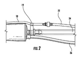
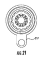
ここで図1−3を参照すると、組織を超音波で断片化および吸引するための本開示の装置の一実施形態が、示される。本開示は、外科手術において組織を超音波で断片化および吸引するための超音波外科手術用装置10を対象とする。概して、超音波外科手術用装置は、外科医が断片化を指示するために使用するためのハンドピース12を含む。ハンドピース12は、外科手術用先端または超音波ホーン14が締結される、トランスデューサ(図示せず)を包囲する。超音波ホーンは、トランスデューサによって給電され、超音波作動され、組織を断片化し、廃物を中心チャネルを介して吸入することができる。超音波ホーン14の遠位端部分13は、送液筒16の遠位端を越えて延在する。超音波ホーン14は、外科手術の間、組織を断片化するように振動される。超音波ホーンは、チタンまたは当技術分野において公知の他の従来の材料から作製されてもよい。
Here, with reference to FIG. 1-3, an embodiment of the apparatus of the present disclosure for ultrasonically fragmenting and aspirating tissue is shown. The present disclosure is directed to an ultrasonic
冷却流体を超音波ホーン14に提供する冷却および潅注システムが、温度を容認可能範囲内に維持するために提供される。ハンドピース12は、筐体15を含み、これは、滅菌可能プラスチックまたは金属から形成されてもよいが、好ましくは、プラスチックである。送液筒16は、潅注流体または液体のための経路を提供し、筐体15の遠位端に接続する。送液筒16は、典型的には、ノーズコーン32を介して、ハンドピース12に接続する。送液筒16は、送液筒管18を含む、またはそこに取り付けられ、開口部17を通して送液筒管18と流体連通してもよい。ノーズコーン32は、ハンドピース12に取り付けられ、超音波ホーン14の内部部分を被覆する。
A cooling and irrigation system that provides cooling fluid to the
潅注管22は、上流で送液筒管18に接続し、外科手術の間、潅注流体を送液筒管18を通して手術部位に供給する。吸引管24は、吸入力と、手術部位から収集キャニスタ(図示せず)への吸引力のための経路とを提供する。代替として、吸引管は、筐体15の外側に搭載されてもよい。送液筒管クリップ19は、手術の間、外科医の所望に応じて、送液筒管18の場所の調節を可能にする。また、電力を装置に提供する、または切替接続を提供するための電気ケーブル26も示される。
The
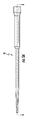
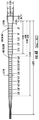
図4は、組織を断片化し、吸引するための前述の超音波外科手術用装置と併用するために好適である、超音波ホーン14を図示する。超音波ホーンは、外部表面120を有し、第1のホーン延在部14aと、ホーン延在部遷移区画112を通して第1のホーン延在部から遠位に延在する、第2のホーン延在部14bと、第2のホーン延在部から遠位に延在する、第3のホーン延在部14cとを含む。超音波ホーンは、付加的ホーン延在部または複数の延在部を有する、もしくは1つのみまたは2つのホーン延在部を有してもよい。超音波ホーン14は、遠位端部分113と、ねじ山付き近位端111と、貫通ボア117と、前置吸引孔または横方向ボア115と、六角形係合部分119とを有する。超音波ホーンは、第1のホーン延在部14a区分におけるより大きい外径と、第2のホーン延在部14b区分におけるより小さい外径とを有する。
FIG. 4 illustrates an
超音波ホーンは、示されるように、段階的ホーンであるが、段階的ではない超音波ホーンも存在することは、公知である。例えば、超音波ホーンは、2つの異なる直径の2つのホーン延在部ではなく、単一の長い延在部を有することができ、単一の長いホーン延在部は、その長さ全体を通して一定直径を有する、またはその長さに沿って徐々に変化する直径、例えば、その長さに沿って遠位に徐々に減少する直径を有することができる。加えて、2つのホーン延在部が、段階的構成を形成し得る場合でも、付加的延在部または複数の延在部が、付加的段を形成する、または任意の見掛け段を形成せず、別の延在部から平滑に遷移してもよい。超音波ホーンは、約5ミル(0.005インチ)超〜14ミル(0.014インチ)の縦方向振幅を伴う超音波周波数範囲内で振動してもよい。 Ultrasonic horns are gradual horns, as shown, but it is known that there are also non-gradual ultrasonic horns. For example, an ultrasonic horn can have a single long extension instead of two horn extensions of two different diameters, and the single long horn extension is constant throughout its length. It can have a diameter or a diameter that gradually changes along its length, eg, a diameter that gradually decreases distally along its length. In addition, even if the two horn extensions can form a stepwise configuration, the additional extension or multiple extensions do not form an additional step or any apparent step. , You may make a smooth transition from another extension. The ultrasonic horn may vibrate within an ultrasonic frequency range with longitudinal amplitudes of more than about 5 mils (0.005 inches) to 14 mils (0.014 inches).
貫通ボア117もまた、第1のホーン延在部14a内のより大きい直径区分と、第2のホーン延在部14b区分内のより小さい直径区分とを有してもよい。貫通ボアの近位のより大きい直径および遠位のより小さい直径部分の直径は、必要に応じて、当業者によって容易に判定され得るような任意の好適な直径を有してもよい。例えば、遠位のより小さい直径の貫通ボア部分は、約0.045インチの直径であってもよい。貫通ボアは、必ずしも、超音波ホーン延在部または複数の延在部の幾何学形状に対応する必要はない。貫通ボアは、段階的方式における2つまたはそれを上回る直径、または別様に、その長さ全体を通して一定の直径もしくはその長さに沿って遠位に徐々に変化する(例えば、減少する)直径を有してもよい。
The through
超音波ホーン14は、略円形であって、送液筒16内に配置される。超音波装置10の動作の間、潅注流体が、開口部17を通して送液筒16の中に供給される。送液筒16および超音波ホーン14は、環状空洞36をその間に画定する。潅注流体は、送液筒16から空洞36を通して超音波ホーン14の遠位端に供給される。横方向ボアが、超音波ホーン14の遠位端の近傍において前置吸引孔115内に形成され、貫通ボア117と連通する。潅注流体が、前置吸引孔115および外科手術部位から貫通ボア117の入口31の中に、断片化された組織、血液等とともに引き込まれ、貫通ボア117および吸引管24を介して、外科手術部位から除去される。横方向ボアは、入口31が詰まるとき、流体が貫通ボア117に進入する代替ルートを提供する。
The
より詳細な側面では、潅注液体、例えば、生理食塩水が、外科手術用先端および組織断片化の部位を冷却するために必要である。本潅注液体は、典型的には、わずか1秒あたり1滴または2滴である、2〜3ml/分の低率で、蠕動ポンプを用いて送液筒に提供される。潅注液体は、超音波ホーンの近位端に供給される。潅注液体は、超音波ホーンの遠位端の近傍に進み、そこで、0.015インチ直径の2つの前置吸引孔が、潅注液の大部分、おそらく、90〜95%を外側ホーン直径に接続する孔を通して中心吸入チャネルに吸入する。本潅注および吸入の作用は、振動チタン金属のための連続的冷却回路を支援し、また、中心チャネル内の血液および組織等の廃物を湿潤させることに役立つ。ある程度の潅注はまた、外科手術部位を冷却し、組織への結合を改善し、腫瘍等の組織の乳化および吸引に必要なキャビテーションを与えるために好ましい。 In a more detailed aspect, an infusion solution, such as saline, is required to cool the surgical tip and site of tissue fragmentation. The irrigation fluid is delivered to the fluid delivery tube using a peristaltic pump at a low rate of 2-3 ml / min, typically only 1 or 2 drops per second. The irrigation liquid is supplied to the proximal end of the ultrasonic horn. The irrigation fluid travels near the distal end of the ultrasonic horn, where two 0.015-inch diameter pre-suction holes connect most of the irrigation fluid, perhaps 90-95%, to the outer horn diameter. Inhale into the central inhalation channel through the hole. This irrigation and inhalation action supports a continuous cooling circuit for vibrating titanium metal and also helps to moisten waste products such as blood and tissues within the central channel. Some irrigation is also preferred to cool the surgical site, improve binding to tissue, and provide the cavitation required for emulsification and aspiration of tissue such as tumors.
ここで図5A、5B、6Aおよび6Bを参照すると、本発明の例示的実施形態が、示される。送液筒16は、超音波ホーンと併用するために、内部表面と、外部表面とを有し、第1のホーン延在部と、第1のホーン延在部から遠位に延在し、第1のホーン延在部の直径より小さい直径を有する、第2のホーン延在部と備える。送液筒は、内部表面51と、外部表面52と、近位端53と、遠位端54とを有し、第1の送液筒延在部16aと、第1の送液筒延在部から遠位に延在し、第1の送液筒延在部の直径より小さい直径を有する、第2の送液筒延在部16bとを備える。付加的送液筒は、第3の送液筒延在部16cを有する。第1および第2の送液筒延在部は、少なくとも部分的に、第1および第2のホーン延在部を包囲または囲繞するように構成される。
Here, with reference to FIGS. 5A, 5B, 6A and 6B, exemplary embodiments of the invention are shown. The
図7Aは、本発明による送液筒16の別の例証であって、図7Bは、先行技術デバイスを示す。図7Bに示されるように、市場における既存の送液筒は、外科手術用先端延在部の腹を中心としてと、その端部の節の近傍とに、疎らな突出部を有する。本外科手術用先端は、60デュロメータ可撓性シリコーン送液筒を利用する。突出部は、大送液筒延在部にわたってのみ位置する。既存のデバイスは、高運動低歪み領域にのみ突出部を有し、送液筒の外部の組織を保護するために不適正である。例えば、CUSA(R) Excel Extended MicroTip Plus(EMT+)外科手術用先端(Integra LifeSciences Corporation, Plainsboro, NJ)および他のCUSA Excel外科手術用先端は、高歪み面積において突出部を利用しない、シリコーン送液筒を採用する。また、疎らな突出部は、既存の送液筒にかかる中程度の荷重下では、拡散され得る。多くの既存の延在される外科手術用先端は、その送液筒の内径上に突出部を有するが、そのホーン延在部の腹、すなわち、最大運動点のみを中心として有する。
FIG. 7A is another illustration of the
先に議論されたように、送液筒は、多くの場合、潅注液体を送達するために採用され、振動外科手術用先端から外科手術用部位までの経路に沿って組織を保護する。トランスデューサは、その長さに沿って振動し、段階的ホーンおよび低減された直径の特殊プロファイルは、振動を増幅させる。実際は、時として、外科医は、外科手術用先端の振動の間、高荷重下で送液筒を組織に対して圧迫し、組織を熱傷させ得る温度上昇を生じさせるであろうことが見出されている。より小さい直径である、1/2波長の第2のホーン延在部を有する外科手術用先端は、より大きい機械的利得に起因して、大きな第1のホーン延在部より大きな運動を有する。振動外科手術用先端に対する送液筒の圧迫は、温度上昇を生じさせ、したがって、熱傷を患者にもたらす潜在性を有し得る。金属作業加熱が、高温になるまで、または破断するまで、薄い金属またはワイヤロッド片を屈曲させることによる歪みに起因して被られ得る。そのような温度上昇の原因が、認められたので、本発明の送液筒は、認められた問題に対処し、そのような温度上昇を防止する。 As discussed earlier, the delivery tube is often employed to deliver the irrigation fluid and protects the tissue along the path from the vibrating surgical tip to the surgical site. The transducer vibrates along its length, and a gradual horn and a special profile with a reduced diameter amplify the vibration. In fact, it has sometimes been found that surgeons will sometimes press on the tissue under heavy load during the vibration of the surgical tip, causing a temperature rise that can burn the tissue. ing. A surgical tip with a second horn extension of 1/2 wavelength, which is smaller in diameter, has more motion than a larger first horn extension due to the larger mechanical gain. Compression of the fluid tube against the vibrating surgical tip can cause an increase in temperature and therefore have the potential to cause burns to the patient. Metalwork heating can be exposed to high temperatures or until it breaks due to strain caused by bending thin metal or wire rod pieces. Since the cause of such a temperature rise has been found, the liquid delivery cylinder of the present invention addresses the recognized problem and prevents such a temperature rise.
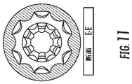
ここで図8A、8B、および9−18に目を向けると、第2の送液筒延在部の内部表面51は、平面領域48(図8A−8B、9、および10の断面図に示されるような平面)、すなわち、突出部間の領域と、第2の送液筒延在部の内部表面の平面領域48と第2のホーン延在部の外部表面との間の接触を限定する、ブリッジ44、46を形成する、複数の突出部42とを備える。斜視図における内部表面51の突出部間の領域48および/または内向きに突出する突出部42は、縦軸Lを中心として略円筒形であるが、種々の形状、サイズ、相対的位置、構造、および数量であってもよく、依然として、本発明の範囲内であることを理解されたい。示される実施形態では、突出部42間の領域48は、弧状である。しかしながら、領域48は、種々の形状または輪郭であってもよいことを理解されたい。
Looking now at FIGS. 8A, 8B, and 9-18, the
本発明の別の側面では、突出部は、第1のホーン延在部、第2のホーン延在部、および/または任意の付加的ホーン延在部上の超音波ホーンの節上またはその近傍もしくはそれを中心とする場所に対応する場所に分散される。共振器によって発生された超音波は、少なくとも1つの節と、少なくとも1つの腹とを有する。腹は、波における最大変位点であって、節は、最小変位点である。突出部は、送液筒の内部表面の平面領域と超音波ホーンの外部表面との間の接触を限定する、1つまたはそれを上回るブリッジを形成する。送液筒はさらに、その内部表面上に、超音波ホーンの腹上またはその近傍もしくはそれを中心とする場所に対応する場所にある、および/または超音波ホーンの節と腹との間等の高歪み勾配および運動の場所に対応する場所にある、突出部を備えてもよい。 In another aspect of the invention, the protrusions are on or near the nodes of the ultrasonic horn on the first horn extension, the second horn extension, and / or any additional horn extension. Or it is distributed to the places corresponding to the places around it. The ultrasonic waves generated by the resonator have at least one node and at least one antinode. The antinode is the maximum displacement point in the wave and the node is the minimum displacement point. The protrusions form one or more bridges that limit the contact between the planar area of the inner surface of the liquid delivery tube and the outer surface of the ultrasonic horn. The liquid delivery tube is further located on or near the ventral of the ultrasonic horn or in a location corresponding to its center, and / or high, such as between the nodes and abdomen of the ultrasonic horn, on its inner surface. A protrusion may be provided at a location corresponding to the strain gradient and location of motion.
好ましくは、第2の送液筒延在部の内部表面の少なくとも一部は、突出部を有する。内部表面は、平方センチメートルあたり少なくとも3つの突出部および好ましくは、平方センチメートルあたり少なくとも5つ突出部を有してもよい。突出部は、1つまたはそれを上回る腹上またはそれを中心とする場所に対応する場所以外、または超音波ホーン上の最大運動点以外の、好ましくは、1つまたはそれを上回るホーン延在部に対応する送液筒の実質的に内部表面全体上、例えば、第2の送液筒延在部の表面全体、第1の送液筒延在部の表面全体、および/または任意の付加的送液筒延在部の付加的表面全体上に存在してもよい。第1および第2の送液筒延在部を有する、送液筒では、大送液筒延在部は、平方センチメートルあたり少なくとも3つの突出部を有し、小送液筒延在部は、平方センチメートルあたり少なくとも5つの突出部を有する。突出部は、好ましくは、より大きい送液筒延在部上のものより高い密度でより小さい送液筒延在部上に存在するが、より小さい送液筒延在部上の突出部は、より大きい送液筒延在部上のものと同一密度またはより大きい送液筒延在部上のものと比べてより低い密度ですらあり得るが、利得、歪み、および運動が、ホーンのより小さい送液筒延在部に対してより大きいため、より大きい直径の送液筒延在部より低い密度の突出部を小直径送液筒延在部上に有することは、稀であると考えられるであろう。 Preferably, at least a part of the inner surface of the second liquid delivery cylinder extending portion has a protruding portion. The inner surface may have at least 3 protrusions per square centimeter and preferably at least 5 protrusions per square centimeter. The protrusion is one or more of the horn extension other than one or more abdomen or a location corresponding to a center thereof, or other than the maximum motion point on the ultrasonic horn, preferably one or more. On substantially the entire internal surface of the corresponding liquid delivery cylinder, for example, the entire surface of the second liquid delivery cylinder extension, the entire surface of the first liquid delivery cylinder extension, and / or any additional It may be present on the entire additional surface of the extension of the liquid delivery tube. In the liquid delivery cylinder having the first and second liquid delivery cylinder extension parts, the large liquid delivery cylinder extension part has at least three protrusions per square centimeter, and the small liquid delivery cylinder extension part is square centimeters. It has at least 5 protrusions per. The overhangs are preferably present on the smaller infusion tube extension at a higher density than those on the larger infusion tube extension, while the overhangs on the smaller infusion tube extension are Gain, distortion, and motion are smaller than those on the horn, although the density may be the same as that on the larger fluid tube extension or even lower than that on the larger fluid tube extension. Since it is larger than the extension of the delivery tube, it is considered rare to have a protrusion with a lower density than the extension of the delivery tube of a larger diameter on the extension of the delivery tube of a smaller diameter. Will.
送液筒16は、外科手術の間、潅注流体を手術部位に供給する。送液筒16は、中空部材であるため、突出部42が、強度のために含まれ、超音波ホーンに接触し得る。突出部42は、送液筒16および超音波ホーンを同心に維持することに役立つ。超音波ホーンは、より小さい直径であって、より大きな機械的利得に起因して、より大きい第1のホーン延在部よりも大きい運動を有する、1/2波長の第2のホーン延在部を有する。突出部のパターン、密度、および領域は、改良されている。突出部は、成型バンプとして、第2のホーン延在部部分に対応する第2の送液筒延在部部分に追加される。加えて、振動加熱は、腹以外の他の高歪み面積にも生じ得ることが分かり、したがって、突出部を伴う面積が、延在された。最後に、単純行における突出部は、それらが拡散し、シリコーン送液筒の薄壁が、振動先端を圧迫することを可能にするように、点または線荷重を伴って送液筒を圧迫することによって分離され得ることが分かっている。その結果、突出部は、より高い密度のより複雑なパターンで設置され、潅注液体がブリッジの真下を流動し続けることを可能にしながら、送液筒の薄壁の圧迫に抵抗するブリッジの提供を補助する。突出部を圧迫するために必要とされるパターン、密度、および力の複雑性を変化させ、突出部の保護の領域を延在させることは、圧迫の際の温度上昇を著しく低減させ、それによって、送液筒によって保護される隣接する組織の熱傷の可能性を低減させることができる。突出部のパターンおよび密度は、ブリッジが高荷重下で形成および持続され、シリコーン送液筒の薄壁が振動ホーンに接触しないように保つように改良され、これらのブリッジは、潅注液体が流動し続けることを可能にする。
The
送液筒は、概して、送液筒が併用される、超音波ホーンと同一形状を有し、段を有していない、もしくは1つまたはそれを上回る段を有し得る、超音波ホーンの外部表面を中心として位置するように構成される。異なる内径の2つの送液筒延在部が、段階的構成を形成するように示されるが、付加的延在部または複数の延在部が、付加的段を形成する、または任意の見掛け段を形成せず、別の延在部から平滑に遷移してもよい。 The liquid delivery tube is generally the outside of the ultrasonic horn, which is used in combination with the liquid delivery tube, has the same shape as the ultrasonic horn, has no steps, or may have one or more steps. It is configured to be centered on the surface. Two liquid delivery tube extensions with different inner diameters are shown to form a stepwise configuration, but the additional extension or multiple extensions form an additional step, or any apparent step. May be smoothly transitioned from another extending portion without forming.
送液筒は、段階的直径を有していない、超音波ホーンと併用するために提供されてもよい。例えば、送液筒は、2つの異なる直径の2つまたはそれを上回る明確に異なる送液筒延在部ではなく、単一伸長送液筒延在部本体を有してもよく、単一伸長送液筒延在部は、その長さ全体を通して一定直径を有する、またはその長さに沿って徐々に変化する直径、例えば、その長さに沿って遠位に徐々に減少する直径を有してもよい。その場合、用語「送液筒延在部」は、伸長延在部本体の送液筒延在部区分を指し得、用語「複数の送液筒延在部」は、任意の明確に異なる遷移点を有していない、2つまたはそれを上回る送液筒延在部区分を指し得る。 The liquid delivery tube may be provided for use with an ultrasonic horn, which does not have a stepwise diameter. For example, a liquid delivery tube may have a single extension liquid delivery tube extension body rather than two or more distinctly different liquid delivery tube extension parts of two different diameters, and a single extension. The extension of the liquid delivery tube has a constant diameter throughout its length, or has a diameter that gradually changes along the length, for example, a diameter that gradually decreases distally along the length. You may. In that case, the term "fluid extension" can refer to the division of the extension main body of the fluid delivery tube, and the term "plurality of delivery tube extension" can be any distinctly different transition. It can refer to two or more liquid delivery tube extension divisions that do not have points.
第3の送液筒延在部16cは、送液筒16の内壁上に6つのリブ57を有する。リブ57は、送液筒の本区分の構造完全性を提供し、外科手術用先端の周囲に挿入されることを可能にし、潅注流体が外科手術用先端の周囲において外科手術用先端の遠位端部分に流動することを可能にする。
The third liquid feeding
図19に示されるように、ブリッジ44、46は、突出部によって形成される。シリコーンの薄壁の点荷重下でも、円筒形外科手術用先端表面は、縦方向および軸方向の両方において、突出部に係合する。突出部は、1つの突出部が略正方形または長方形様式で配列される全4つの隣接する突出部の中心に心合されるように、交互された行および列に分散される。突出部は、縦方向ブリッジ44と、また、軸方向ブリッジ46とを形成する。円筒形表面は、抵抗の増加および荷重の分散を生じさせずに、その間に嵌合し、突出部を拡散させることができない。潅注液体は、多軸ブリッジ下で回路を見出し続けることができる。
As shown in FIG. 19, the
送液筒上の突出部は、球体の形態であってもよい。図6Bに示される実施形態では、第1のより大きい送液筒延在部上の突出部の球面半径は、約0.047インチであって、第2のより小さい送液筒延在部上の突出部の球面半径は、約0.028インチである。本実施形態では、第1の送液筒延在部上の球状突出部は全て、同一サイズを有し、第2の送液筒延在部上の球状突出部は全て、同一サイズを有し、第1の送液筒延在部上の球状突出部は、第2の送液筒延在部上のものより大きい。球体は、少なくとも部分的に、超音波ホーンのサイズおよび送液筒の設計強度に応じて、例示的実施形態に示されるものと異なるサイズを有してもよい。第1のより大きい送液筒延在部上の突出部の球面半径は、約0.01〜約0.10インチまたは約0.02〜約0.08インチの範囲内であってもよく、第2のより小さい送液筒延在部上の突出部の球面半径は、約0.01〜約0.08インチまたは約0.01〜約0.05インチの範囲内であってもよい。 The protrusion on the liquid delivery cylinder may be in the form of a sphere. In the embodiment shown in FIG. 6B, the spherical radius of the protrusion on the first larger fluid delivery tube extension is about 0.047 inches and on the second smaller fluid delivery tube extension. The spherical radius of the protrusion is about 0.028 inches. In the present embodiment, all the spherical protrusions on the first liquid delivery cylinder extending portion have the same size, and all the spherical protrusions on the second liquid delivery cylinder extending portion have the same size. , The spherical protrusion on the first liquid feeding cylinder extending portion is larger than that on the second liquid feeding cylinder extending portion. The sphere may, at least in part, have a size different from that shown in the exemplary embodiments, depending on the size of the ultrasonic horn and the design strength of the liquid delivery tube. The spherical radius of the protrusion on the first larger delivery tube extension may be in the range of about 0.01 to about 0.10 inches or about 0.02 to about 0.08 inches. The spherical radius of the protrusion on the second smaller extension of the liquid delivery tube may be in the range of about 0.01 to about 0.08 inches or about 0.01 to about 0.05 inches.
図面に示されるような実施形態では、縦軸を中心として各行に6つの球状突出部が、存在する。第1の送液筒延在部上の突出部は、本実施形態では、全て同じ形状およびサイズであるが、それらは、同じである必要はない。同様に、第2の送液筒延在部上の突出部は、全て同じ形状およびサイズであるが、それらは、同じである必要はない。より大きい送液筒延在部上の突出部は、好ましくは、概して、より小さい送液筒延在部のものより大きいが、しかし、より大きい送液筒延在部上の突出部は、より小さい送液筒延在部上のものと同一サイズである、またはより小さい送液筒延在部のものより小さくてもよい。 In an embodiment as shown in the drawings, there are six spherical protrusions in each row centered on the vertical axis. The protrusions on the extension of the first liquid delivery tube all have the same shape and size in the present embodiment, but they do not have to be the same. Similarly, the protrusions on the second liquid delivery tube extension all have the same shape and size, but they do not have to be the same. The protrusion on the larger fluid delivery tube extension is preferably larger than that of the smaller fluid delivery tube extension, but the protrusion on the larger fluid delivery tube extension is more. It may be the same size as the one on the small delivery tube extension, or smaller than that on the smaller delivery tube extension.
換言すると、突出部は、約0.02〜約0.14(約0.5mm〜約3.5mm)、好ましくは、約0.04〜約0.12インチ(約1.0mm〜約3.0mm)の平均球状直径を有してもよい。第1および第2のホーン延在部を有する、前述の実施形態では、より大きい送液筒延在部上の突出部は、約0.09〜約0.10インチ(約2.2mm〜約2.6mm)の平均直径を有してもよく、より小さい送液筒延在部上の突出部は、約0.05〜約0.06インチ(約1.2mm〜約1.6mm)の平均直径を有してもよい。 In other words, the protrusion is about 0.02 to about 0.14 (about 0.5 mm to about 3.5 mm), preferably about 0.04 to about 0.12 inch (about 1.0 mm to about 3.). It may have an average spherical diameter (0 mm). In the aforementioned embodiment having the first and second horn extension, the overhang on the larger delivery tube extension is about 0.09 to about 0.10 inch (about 2.2 mm to about 2.2 mm). It may have an average diameter of 2.6 mm), and the protrusions on the smaller extension of the delivery tube are about 0.05 to about 0.06 inches (about 1.2 mm to about 1.6 mm). It may have an average diameter.
突出部は、示されるような球状形態である必要はなく、任意の好適な形状および寸法を有してもよい。突出部は、約0.01〜約0.10インチ、約0.01〜約0.06インチ(約0.2mm〜約1.5mm)、または約0.01〜約0.04インチ(約0.2mm〜約1.0mm)の範囲内である平均高さを有してもよい。例えば、より大きい第1のホーン延在部と、より小さい第2のホーン延在部とを備える、段階的超音波ホーンと併用するための送液筒のある実施形態では、大送液筒延在部上の突出部は、0.02〜約0.06インチ(約0.5〜約1.5mm)の平均高さを有してもよく、小送液筒延在部上のものは、0.01〜約0.03インチ(約0.2mm〜約0.8mm)の平均高さを有してもよい。 The protrusions do not have to be spherical as shown and may have any suitable shape and dimensions. The protrusions are about 0.01 to about 0.10 inch, about 0.01 to about 0.06 inch (about 0.2 mm to about 1.5 mm), or about 0.01 to about 0.04 inch (about 0.01 to about 0.04 inch). It may have an average height in the range of 0.2 mm to about 1.0 mm). For example, in an embodiment having a liquid delivery tube for use with a stepwise ultrasonic horn, which comprises a larger first horn extension and a smaller second horn extension, a large delivery tube extension. The protrusion on the existing portion may have an average height of 0.02 to about 0.06 inch (about 0.5 to about 1.5 mm), and the protrusion on the small liquid delivery cylinder extending portion may have an average height of 0.02 to about 0.06 inch (about 0.5 to about 1.5 mm). , 0.01 to about 0.03 inches (about 0.2 mm to about 0.8 mm) may have an average height.
先に述べられたように、送液筒は、円形断面を有するように図示および説明されるが、突出部は、略円筒形または円形断面を有していないことを理解されたい。突出部は、本発明の精神から逸脱することなく、任意の好適な幾何学形状であることができる。加えて、突出部の高さ、直径、および/または密度は、送液筒の内部表面全体を横断して、または送液筒延在部もしくはその任意の領域の内部表面を横断して一貫する必要はない。 As mentioned earlier, the liquid delivery tube is illustrated and described to have a circular cross section, but it should be understood that the protrusions do not have a substantially cylindrical or circular cross section. The protrusion can have any suitable geometric shape without departing from the spirit of the present invention. In addition, the height, diameter, and / or density of the protrusions are consistent across the entire internal surface of the liquid delivery tube or across the internal surface of the liquid delivery tube extension or any region thereof. No need.
目視観察および物理的温度監視を用いて、送液筒の高荷重は、薄壁シリコーンが外科手術用先端に接触し得るように突出部を拡散させ得ることが、判定された。これは、突出部の密度、先端の半径、印加される力および点または線荷重、ならびに二次的にゴム送液筒のデュロメータに依存する。突出部の密度の増加は、本質的に、荷重を支持する突出部の数によって荷重を除算する、分散される荷重に対する抵抗を提供する。突出部は、点荷重に対してさえもブリッジを形成し、振動先端に接触する薄壁に対する抵抗度を提供する。これは、摩擦および加熱が点荷重および点荷重力の大きさに伴って増加する理由のうちの1つである。合理的かつ過剰な荷重は、低減された加熱に起因して監視された改良温度を用いて支持され得ることが分かっている。突出部によって形成されるブリッジは、送液筒の圧迫下でさえ、潅注液体のための経路を可能にする。すなわち、ブリッジ下で流動する。突出部の密度は、小送液筒延在部のより小さい半径をより良好に支持するように増加されることができ、パターンは、ブリッジを縦方向および軸方向の両方に提供するように調節されることができる。 Using visual observation and physical temperature monitoring, it was determined that a high load on the delivery tube could diffuse the protrusion so that the thin-walled silicone could contact the surgical tip. This depends on the density of the protrusions, the radius of the tip, the applied force and point or line load, and secondarily the durometer of the rubber feeder. Increasing the density of the protrusions essentially provides resistance to the distributed load, which divides the load by the number of protrusions that support the load. The protrusions form a bridge even against point loads and provide resistance to thin walls in contact with the vibrating tip. This is one of the reasons why friction and heating increase with the magnitude of point loads and point load forces. It has been found that reasonable and excessive loads can be supported with improved temperatures monitored due to reduced heating. The bridge formed by the overhang allows a pathway for the irrigation fluid, even under compression of the delivery tube. That is, it flows under the bridge. The density of the protrusions can be increased to better support the smaller radius of the tubule extension and the pattern is adjusted to provide the bridge both longitudinally and axially. Can be done.
図20および21は、本発明による、送液筒216の別の実施形態を示す。送液筒は、送液筒管接続区分217を有する。図22に示されるように、送液筒は、送液筒管接続区分217において、例えば、成型または当技術分野において公知の他の方法によって、送液筒管218に接続する。送液筒管218は、潅注管22との接続のためのルアー継手211を有する。
20 and 21 show another embodiment of the
送液筒は、シリコーン、他のエラストマ、または他の好適な材料から作製されることができる。送液筒管は、送液筒の材料と同一または異なる、シリコーン、他のエラストマ、または他の好適な材料から作製されることができる。例えば、約0.01〜0.05インチの厚さの薄壁シリコーン送液筒が、使用されてもよい。好ましい材料は、Dow Corning製のシリコーンゴム化合物等のシリコーンである。シリコーンは、潅注液の損失または外科手術用先端の詰まり等の壊滅的な条件下でも完全性を維持する。牽引力または荷重のみでも、神経を損傷させ得、シリコーンゴムは、剛性送液筒に対してある程度の緩衝材を提供することが、公知である。シリコーンは、ゴムであって、本材料は、外科手術用先端から重要な生体構造に伝搬し得る、超音波を減衰させる。60デュロメータ等のシリコーンは、可撓性であって、湾曲外科手術用先端に共形化し、外科医の顕微鏡下で増加される可視化において臨床利点を提供する。当業者に公知の他の好適な材料もまた、送液筒を作製するために使用されてもよい。 The liquid delivery tube can be made of silicone, other elastomer, or other suitable material. The liquid delivery tube can be made of silicone, other elastomer, or other suitable material that is the same as or different from the material of the liquid delivery tube. For example, a thin-walled silicone liquid delivery tube with a thickness of about 0.01 to 0.05 inches may be used. A preferred material is silicone, such as a silicone rubber compound from Dow Corning. Silicone maintains integrity even under catastrophic conditions such as loss of irrigation fluid or clogging of surgical tips. It is known that traction or load alone can damage nerves, and silicone rubber provides some cushioning material for rigid fluid delivery tubes. Silicone is a rubber, the material of which attenuates ultrasonic waves that can propagate from surgical tips to critical biostructures. Silicones, such as 60 durometers, are flexible and symmetry with curved surgical tips, providing clinical benefits in increased visualization under the surgeon's microscope. Other suitable materials known to those of skill in the art may also be used to make the liquid delivery tube.
ポリメチルペンテン(PMP)、アセタールホモポリマー樹脂(Dupont(R)Delrin(R)材料等)、およびポリテトラフルオロエチレン(PTFE)等の材料から作製される剛性送液筒もまた、検討される。しかしながら、剛性送液筒は、潅注液の損失または外科手術用先端の詰まり等の壊滅的な状況下において、亀裂および溶融等の問題を被り得る。剛性送液筒、例えば、硬質ポリマーから作製される送液筒は、接触力を分散させ、それによって、集中される摩擦加熱を低減させる際により効果的であり得る。増加されるデュロメータから追加される堅度は、荷重をより均一に分散させ、したがって、加熱を低減させることに役立ち得る。また、剛性送液筒は、外科医が、より長い外科手術用先端の送液筒を安定させる、または把持し得るように、外科手術用先端の有用な範囲を延在させることが、明白である。しかしながら、剛性送液筒は必要されるであろう隙間および屈曲角度が先端の遠位端および外科手術用部位への外科医の視線を妨害するため、湾曲先端に好適ではない場合がある。可撓性シリコーン材料は、先端の形状に容易に共形化し、先端に対して緊密に嵌合し、設計の嵩張りを低減させ、外科医にはるかに良好な視線を提供するため、これらの先端に対してより良好に機能する。同様に、内部バンプもまた、荷重をより均一に分散させ、加熱を低減させることに役立ちながら、同時に、より均一な潅注流を生成し、シンク熱を除去することに役立ち得る。 Rigid liquid delivery tubes made from materials such as polymethylpentene (PMP), acetal homopolymer resins (DuPont (R) Delrin (R) materials, etc.), and polytetrafluoroethylene (PTFE) are also considered. However, rigid fluid delivery tubes can suffer from problems such as cracking and melting under catastrophic conditions such as loss of irrigation fluid or clogging of surgical tips. Rigid liquid delivery tubes, such as those made from rigid polymers, can be more effective in dispersing contact forces and thereby reducing concentrated frictional heating. The added stiffness from the increased durometer can help distribute the load more evenly and thus reduce heating. It is also clear that the rigid fluid delivery tube extends a useful range of the surgical tip so that the surgeon can stabilize or grip the longer surgical tip delivery tube. .. However, rigid fluid tubes may not be suitable for curved tips because the gaps and flexion angles that may be required obstruct the surgeon's line of sight to the distal end of the tip and the surgical site. These tips because the flexible silicone material easily conforms to the shape of the tips, fits tightly to the tips, reduces design bulk and provides the surgeon with a much better line of sight. Works better against. Similarly, internal bumps can also help distribute the load more evenly and reduce heating, while at the same time producing a more uniform irrigation flow and removing sink heat.
本発明による送液筒は、成型または他の従来の製造方法によって作製されることができる。送液筒は、CUSA Excel外科手術用先端、CUSA NXT 35kHz延長先端、または市場における、もしくは開発中である、他の超音波外科手術用吸引器具等の既存の超音波外科手術用先端と併用されることができる。外科手術用先端は、直線または湾曲であってもよく、異なる長さまたは先端設計を有してもよい。用途の観点から、本発明による、超音波ホーンと、送液筒とを備える、超音波外科手術用装置は、頭蓋底外科手術および経蝶形骨洞または内視鏡下鼻腔アプローチを実施するとき等の超音波吸引器の公知の用途に有用である。 The liquid feed tube according to the present invention can be manufactured by molding or other conventional manufacturing methods. The liquid delivery tube is used in combination with the CUSA Excel surgical tip, CUSA NXT 35 kHz extension tip, or existing ultrasonic surgical tips such as other ultrasonic surgical suction instruments on the market or under development. Can be done. The surgical tip may be straight or curved and may have different lengths or tip designs. From the point of view of application, the ultrasonic surgical device according to the present invention, which comprises an ultrasonic horn and a liquid delivery tube, is used when performing skull base surgery and a transsphenoid sinus or endoscopic nasal approach. It is useful for known applications of ultrasonic aspirators such as.
温度データは、ホットスポットまたは最大温度が、EMT Plus送液筒の小ホーン延在部(第2のホーン延在部)の腹以外であったことを示した。側方荷重に起因した加熱の観点から、先端の長さに沿って最も問題となる面積は、現在付加的安全性考慮が設計に成されていない、小ホーン延在部に沿って位置する。これは、運動および最大歪み勾配が加熱に寄与する場所である。 Temperature data showed that the hotspot or maximum temperature was other than the belly of the small horn extension (second horn extension) of the EMT Plus fluid delivery tube. From the point of view of heating due to lateral loads, the most problematic area along the length of the tip is located along the small horn extension, which is not currently designed with additional safety considerations. This is where motion and maximum strain gradients contribute to heating.
シリコン送液筒が、基準研究を設計する際、そして死体ラボにおいて、プロトタイプ化され、試験された。これらの研究における定量的査定は、公称、高、および過剰な荷重下で温度を低減させる際に測定可能な改良を示す。 Silicone tubing was prototyped and tested when designing baseline studies and in corpse laboratories. Quantitative assessments in these studies show measurable improvements in reducing temperature under nominal, high, and overload.
実施例1.超音波ホーンの運動
EMT Plus送液筒は、第1のホーン延在部と、第2のホーン延在部と、第3のホーン延在部とを有する。試験の説明および実施例における結果では、第2のホーン延在部は、本明細書では、追加ホーン延在部または追加延在部と称され、第1のホーン延在部は、従来のホーン延在部または従来の延在部と称される。
Example 1. Motion of ultrasonic horn The EMT Plus liquid feeding cylinder has a first horn extending portion, a second horn extending portion, and a third horn extending portion. In the description of the test and the results in the examples, the second horn extension is referred to herein as an additional horn extension or an additional horn extension, and the first horn extension is a conventional horn. It is called the extension part or the conventional extension part.
運動は、有限要素分析(FEA)を用いてモデル化され、結果は、図23A−Cに示される。追加延在部は、従来の延在部の約4倍の運動を有する。 The motion is modeled using finite element analysis (FEA) and the results are shown in FIGS. 23A-C. The additional extension has about four times the motion of the conventional extension.
実施例2.超音波ホーン上の高歪み領域の判定
高歪み面積における加熱の発見は、外科手術用先端および圧迫された送液筒に沿って「ホットスポット」を探査する際に生じた。外科手術用先端の振幅は、歪みに伴って遂行される。ばねの変位または伸長は、超音波ホーンとの類似性を提供し、ホーンの端部における運動は、物理的に、ばねの代わりに、ホーンの金属の伸展に起因する。伸長は、ホーンの長さに沿った歪みの積分であって、長さの変化によって与えられるものは、以下の方程式(1)に示されるように、長さ間の変化/長さ×全長と等しい。
![]()
![]()
屈曲歪みからの粒子摩擦は、金属を加熱させ、疲労させ得る。超音波ホーンおよび航空機において使用されるようなチタンは、破損せずに、非常に高疲労またはサイクル率に耐えることができる。例えば、屈曲における伸展の極限の形態である、25〜50kHzまたは25,000〜50,000サイクル/秒の超音波周波数における粒子運動を伴う高歪みの接触領域は、加熱を生じさせ、熱を定常送液筒に伝導させ得る。 Particle friction from flexion strain can heat and fatigue the metal. Titanium, as used in ultrasonic horns and aircraft, can withstand very high fatigue or cycle rates without damage. For example, a highly strained contact region with particle motion at an ultrasonic frequency of 25 to 50 kHz or 25,000 to 50,000 cycles / second, which is the extreme form of extension in flexion, causes heating and keeps the heat steady. Can be conducted to the liquid feed tube.
EMT Plusに関する高歪み領域は、図24にFEAを用いて示される。突出部が高運動低歪み領域にのみにある、先行技術デバイスは、送液筒が高歪み領域に対して圧迫される場合、送液筒の外部の組織を保護するために不適正であることが明白となる。FEAは、高歪み領域を呈する。運動最大領域、すなわち、腹を中心として生じることが公知の高温もまた、高歪み粒子運動の面積に対する送液筒圧迫下で生じ得ることが判定された。 The high strain region for EMT Plus is shown in FIG. 24 using FEA. Prior art devices with protrusions only in the high-motion, low-strain areas are inadequate to protect the tissue outside the liquid carrier when the liquid carrier is compressed against the high-strain area. Becomes clear. FEA exhibits a high strain region. It has been determined that the maximum motion region, i.e., the high temperature known to occur centered on the abdomen, can also occur under pressure on the feeder with respect to the area of high strain particle motion.
実施例3.Extended MicroTip Plusのための送液筒
ホーン延在部に対する送液筒上の圧迫に起因する高温の問題に対処するために、Extended MicroTip Plus(EMT+)送液筒に、変更が行われた。これらの潜在的複雑化のいくつかの場所は、鼻内アプローチにおける小延在部と関連付けられている。突出部は、運動最大領域、すなわち、腹を中心としてだけではなく、また、高歪み粒子運動の面積における、より大きい面積まで延在された。
Example 3. Liquid Cylinder for Extended MicroTip Plus Changes have been made to the Extended MicroTip Plus (EMT +) fluid cylinder to address the problem of high temperatures caused by pressure on the fluid cylinder over the horn extension. Some locations of these potential complications have been associated with small extensions in the intranasal approach. The protrusions were extended not only around the area of maximum motion, i.e., the abdomen, but also to a larger area in the area of high strain particle motion.
新しいEMT+送液筒は、DowCorning Class VI Liquid Silicone Rubber Elastomer C6−560において成型された。本材料は、204℃まで熱安定し、高圧滅菌されることができ、8時間の後硬化後、引張強度8.55MPaを有する。後硬化後のデュロメータ硬さShore Aは、60である。その引裂強度は、後硬化後、50.7kN/mである。 The new EMT + delivery tube was molded in Dow Corning Class VI Liquid Silicone Elastomer C6-560. This material is thermally stable up to 204 ° C., can be sterilized under high pressure, and has a tensile strength of 8.55 MPa after 8 hours of post-curing. The durometer hardness Shore A after post-curing is 60. Its tear strength is 50.7 kN / m after post-curing.
実施例4.死体ラボ試験
死体ラボでは、外科医が、湾曲Extended MicroTip Plusおよびその送液筒の長さにわたって生体構造によって制約されるときの鼻腔内で達成可能な力を感じ取るように求められた。外科医は、力が死体鼻腔内での外科医の感覚に対応するように査定され得るように、小直径延在部の腹に直接設置されたロードセルを伴って、死体の外側からハンドピースおよび外科手術用先端に力を入れるように求められた。外科医は、最大荷重でさえある、鼻腔内で予期される程度まで、送液筒および外科手術用先端に荷重をかけるように求められた。次いで、外科医は、本側方荷重が予期されないであろうように、明らかに過剰であると感じる力を付与するように求められた。
Example 4. Cadaver Lab Test In the cadaver lab, the surgeon was asked to feel the achievable force in the nasal cavity when constrained by the biostructure over the length of the curved Extended MicroTip Plus and its delivery tube. The surgeon will perform handpieces and surgery from the outside of the corpse, with a load cell placed directly on the abdomen of the small diameter extension so that the force can be assessed to correspond to the surgeon's sensations within the corpse nasal cavity. I was asked to put more effort into the tip. The surgeon was asked to load the fluid tube and surgical tip to the extent expected within the nasal cavity, which is even the maximum load. The surgeon was then asked to apply a force that clearly felt excessive, so that the lateral load would not be expected.
外科医は、小延在部において達成され得るが、使用するであろうものより有意に高い力が、0.6Nであると考えた。約0.9N力が、同様に、大ホーン延在部において定量化された。外科医は、荷重がこれらのレベルより高いであろう可能性が低いと感じ、任意の荷重を達成するためにより高い力で幾分歪みをかけていた。温度データが、次いで、送液筒に接着され、鼻腔内の鼻甲介に対して圧迫された熱電対を用いて、死体断片において入手された。外科医は、自ら力を付与しながら、極大温度が達成されるまでのみ荷重を維持した。図25および26は、異なる力下での先端上の異なる場所において測定された通常荷重を示す。 The surgeon considered that a significantly higher force, which could be achieved in the small extension, but would be used, was 0.6N. Approximately 0.9 N force was similarly quantified in the large horn extension. The surgeon felt that the loads were unlikely to be higher than these levels and was somewhat strained with higher forces to achieve any load. Temperature data were then obtained in the corpse fragment using a thermocouple that was glued to the tub and pressed against the turbinate in the nasal cavity. The surgeon maintained the load only until the maximum temperature was reached, applying force himself. Figures 25 and 26 show normal loads measured at different locations on the tip under different forces.
データが、表1および表2に記録されるように、外科手術用先端および送液筒の延在部の腹を中心として2つの場所において入手され、それぞれ、図27Aおよび27Bのチャートにプロットされた。

開始死体温度は、19℃であって、ベースライン商業用送液筒の最大温度は、小延在部の腹を中心として高荷重下で33.3℃、大延在部の高荷重下で45.7℃と定量化された。大延在部は、通常、鼻内アプローチにおいて鼻腔内にないであろうが、いくつかの拡張鼻内アプローチでは挿入され得ることに留意されたい。本商業用送液筒では、小延在部には、突出が存在せず、大延在部は、より低い密度の突出部を有していた。温度が、次いで、本発明による、改良されたパターン、密度、および突出部の延在領域を伴う、60デュロメータプロトタイプ送液筒を用いて監視された。改良された送液筒に関する外科医の感覚による公称〜高荷重は、小延在部に関して29.8℃、大延在部に関して24.6℃をもたらした。 The starting corpse temperature is 19 ° C, and the maximum temperature of the baseline commercial liquid delivery tube is 33.3 ° C under high load centering on the abdomen of the small extension, and under high load of the large extension. It was quantified at 45.7 ° C. It should be noted that the large extension will usually not be intranasal in the intranasal approach, but can be inserted in some dilated intranasal approaches. In this commercial liquid delivery tube, there were no protrusions in the small extension, and the large extension had lower density protrusions. Temperature was then monitored using a 60-durometer prototype liquid delivery tube with improved patterns, densities, and extended areas of protrusions according to the invention. The surgeon's sense of nominal to high load on the improved fluid delivery tube resulted in 29.8 ° C for the small extension and 24.6 ° C for the large extension.
実施例5.点荷重試験
可変荷重装置が、点荷重試験を行う際に使用された。本装置は、取り付けられたカスタム木製ロードセルを含む。ロードセルは、送液筒表面に対して法線方向であって、小延在部の腹に位置する。温度測定のための熱電対は、木製ロードセルと送液筒との間に位置する。60デュロメータ35kHz ELT送液筒(Albright)に関する試験手順は、以下の通りである。(1)35kHz神経試験ハンドピースおよび35kHz延長試験先端をCUSA NXT試験コンソールに取り付ける。35kHz延長60デュロメータ送液筒をハンドピース先端アセンブリに取り付ける。(2)T−タイプ熱電対を小延在部の腹領域における送液筒の外側に取り付ける。カスタム木製点ロードセルをChatillon力ゲージに取り付け、熱電対にわたって直接的に送液筒に荷重をかける。ロードセルが送液筒表面に対して法線方向であることを確実にする。(3)ロードセルの荷重を0.6Nに調節する。熱電対の開始温度を記録する。送液筒にプライミングし、次いで、温度が安定化するまで、コンソールを100%吸引、3mL/分潅注、および100%振幅で起動させる。本温度を記録する。本ステップを5回繰り返し、毎回、先端に再荷重する。(4)ステップ4.3を0.9Nおよび1.2Nの荷重を用いて繰り返す。(5)T−タイプ熱電対を除去し、より大きい延在部の腹領域における送液筒の外側に取り付ける。再び、熱電対にわたって直接的に送液筒に荷重をかけ、ロードセルが送液筒表面に対して法線方向であることを確実にする。(6)ロードセルを0.9Nに調節する。熱電対の開始温度を記録する。送液筒にプライミングし、次いで、温度が安定化するまで、コンソールを100%吸引、3mL/分潅注、および100%振幅で起動する。本温度を記録する。本ステップを5回繰り返し、毎回、先端に再荷重する。(7)ステップ4.6を荷重1.35Nおよび1.8Nを用いて繰り返す。(8)送液筒を除去し、別の35kHz延長60デュロメータ送液筒と置換する。3つの35kHz延長60デュロメータ送液筒が試験されるまで、ステップ4.2−4.7を繰り返す。
Example 5. Point load test A variable load device was used to perform the point load test. The device includes a custom wooden load cell installed. The load cell is located in the normal direction with respect to the surface of the liquid delivery cylinder and is located on the ventral side of the small extension portion. The thermocouple for temperature measurement is located between the wooden load cell and the liquid delivery tube. The test procedure for the 60 durometer 35 kHz ELT liquid delivery tube (Albright) is as follows. (1) Attach the 35 kHz nerve test handpiece and the 35 kHz extension test tip to the CUSA NXT test console. Attach the 35
図28A(従来の送液筒)および28B(最新の発明による送液筒)に示されるように、点荷重条件下では、本発明に従って構成される60デュロメータ送液筒は、より高い密度および改良されたパターンの突出部を用いて、著しく低減された温度を呈した。最大温度が取得されるまで30秒またはそれを上回る時間がかかることに留意されたい。送液筒は、長時間にわたって過剰な荷重下で高温をもたらす領域において圧迫されることになるであろう。改良は、より高い密度の改良された突出部パターンを用いて、低減された温度をもたらした。 As shown in FIGS. 28A (conventional liquid delivery cylinders) and 28B (liquid delivery cylinders according to the latest invention), under point loading conditions, 60 durometer liquid delivery cylinders constructed according to the present invention have higher densities and improvements. The overhanging part of the patterned pattern was used to exhibit a significantly reduced temperature. Note that it takes 30 seconds or more to obtain the maximum temperature. The liquid delivery tube will be squeezed in areas that result in high temperatures under excessive load for extended periods of time. The improvement resulted in a reduced temperature with a higher density of improved protrusion patterns.
実施例6.付加的点荷重試験
最悪の場合の試験が、図29A−Dに示されるように、低熱伝導性材料によって囲繞される熱電対の略点荷重を用いて実施される。加えて、静的荷重が、外科医が有意な時間量にわたって外科手術用先端および送液筒を具体的位置に保つことになる場合等、長時間後の温度を査定する際に想定される。図30に示されるように、印加される点荷重に伴って最大温度の送液筒外側表面上のホットスポットが、事前に探査された。この場合、最大温度は、小延在部の腹以外であることが見出された。最高ホットスポットは、最大運動点以外かつ高歪み勾配領域内にあることに起因して最大となり得る。本点と歪み勾配最大値を関連付けるためのさらなる試験が、実施され得る。温度最大は、腹以外にあることが明白であって、腹以外におけるホットスポットの本発見およびより高い密度の突出部の拡張領域の実装は、特許出願の原理および新しいシリコーン送液筒の改良された設計である。
Example 6. Additional Point Load Tests The worst case test is performed using the near point load of the thermocouple surrounded by a low thermal conductive material, as shown in FIGS. 29A-D. In addition, static loads are envisioned when assessing temperature after a long period of time, such as when the surgeon will hold the surgical tip and delivery tube in a specific position for a significant amount of time. As shown in FIG. 30, hot spots on the outer surface of the liquid delivery cylinder at the maximum temperature with the applied point load were preliminarily explored. In this case, the maximum temperature was found to be other than the abdomen of the small extension. The highest hotspot can be maximal due to being outside the maximum motion point and within the high strain gradient region. Further tests may be performed to correlate this point with the maximum strain gradient. It is clear that the maximum temperature is outside the abdomen, and the present discovery of hotspots outside the abdomen and the implementation of extended regions of higher density protrusions are improvements to the patent application principle and the new silicone delivery tube. Designed.
初期比較試験結果が、提供される。比較試験のために、100%振幅、3ml/分、および100%吸引が、Curved Extended MicroTip Plus外科手術用先端のために使用された。荷重毎の表3におけるこれらのデータは、異なる材料および仕上げの測定値を組み合わせる。20%を上回る改良が、最悪の場合の点荷重にもたらされる。異なるデュロメータ表面仕上げおよびシリコーン材料が、試験で査定されたことに留意されたい。最初の試験は、異なる加工プロセスを含んだ。加えて、研究は、PTFEコーティングシリコーンで行われた。突出部は、温度上昇に及ぼす顕著な影響であって、したがって、既存の60デュロメータ商業用格付けが、コーティングを伴わないDow Corning Siliconeとともに採用される。
温度上昇に及ぼす荷重の影響が、組織の潜在的熱傷に関するいくつかの懸念が挙げられていた、鼻内用途における予期される力を超えて査定された。これらのデータは、非常に高い荷重に関して、図31に示される。送液筒設計の利点は、高荷重において広く認められた。低減された温度上昇が、全ての側方荷重において観察された。本試験では、結果は、20%を上回る改良を示した。 The effect of load on temperature rise was assessed beyond the expected force in nasal applications, which raised some concerns about potential tissue burns. These data are shown in FIG. 31 for very high loads. The advantages of the liquid delivery tube design were widely recognized at high loads. Reduced temperature rise was observed at all lateral loads. In this study, the results showed an improvement of over 20%.
研究は、点荷重が、増加力下の温度上昇のための送液筒設計の最悪の場合の比較を提供した一方、分散荷重は、臨床症例により近似し、潜在的熱傷部位に示された幾分応従性の組織に起因して負担が低いことを示した。 The study provided a worst-case comparison of the delivery tube design for temperature rise under increasing force, while the distributed load was closer to the clinical case and was shown at the potential burn site. It was shown that the burden was low due to the participatory organization.
本発明のいくつかの実施形態を本明細書で説明および図示したが、当業者は、本明細書で説明される機能を果たし、および/または、結果ならびに/もしくは利点のうちの1つまたはそれを上回るものを得るための種々の他の手段および/もしくは構造を容易に想定し、そのような変形例ならびに/もしくは修正のそれぞれは、本明細書で説明される本発明の範囲内であると見なされる。より一般的には、当業者は、本明細書で説明される全パラメータ、寸法、材料、および構成は、例示的であることを意味し、実際のパラメータ、寸法、材料、ならびに/または構成は、本発明の教示が使用される、1つもしくは複数の具体的用途に依存することを、容易に理解するであろう。当業者は、日常的にすぎない実験を使用して、本明細書で説明される本発明の具体的実施形態の多くの均等物を認識するか、または確認することができるであろう。したがって、前述の実施形態は、一例のみとして提示され、添付の請求項およびその同等物の範囲内で、具体的に説明ならびに請求される以外の方法で本発明が実践されてもよいことを理解されたい。本開示の本発明の実施形態は、本明細書で説明される、各個別特徴、システム、部品、材料、キット、および/または方法を対象とする。加えて、そのような特徴、システム、部品、材料、キット、および/または方法が相互に矛盾していなければ、2つもしくはそれを上回るそのような特徴、システム、部品、材料、キット、および/または方法の任意の組み合わせが、本開示の本発明の範囲内に含まれる。 Although some embodiments of the invention have been described and illustrated herein, those skilled in the art will perform the functions described herein and / or one of the results and / or advantages thereof or the like. Various other means and / or structures for obtaining more than are readily envisioned, and each such variant and / or modification is within the scope of the invention described herein. Be considered. More generally, one of ordinary skill in the art will mean that all parameters, dimensions, materials, and configurations described herein are exemplary, with actual parameters, dimensions, materials, and / or configurations. , It will be readily appreciated that the teachings of the present invention depend on one or more specific uses in which they are used. One of ordinary skill in the art will be able to recognize or confirm many equivalents of the specific embodiments of the invention described herein using experiments that are only routine. Therefore, it is understood that the above-described embodiment is presented as an example only, and the present invention may be practiced in a manner other than those specifically described and claimed within the scope of the appended claims and their equivalents. I want to be. Embodiments of the present invention of the present disclosure cover each individual feature, system, component, material, kit, and / or method described herein. In addition, if such features, systems, parts, materials, kits, and / or methods are not inconsistent with each other, two or more such features, systems, parts, materials, kits, and / Alternatively, any combination of methods is included within the scope of the present invention of the present disclosure.
本明細書で定義され使用されるような、全定義は、辞書的定義、参照することによって組み込まれた文書中の定義、ならびに/または定義された用語の通常の意味に優先するものと理解されたい。 All definitions, as defined and used herein, are understood to supersede dictionary definitions, definitions in documents incorporated by reference, and / or the usual meanings of defined terms. sea bream.
本明細書および本請求項で使用されるような、「1つの」という不定冠詞は、明確にそれとは反対に示されない限り、「少なくとも1つの」を意味すると理解されたい。 As used herein and in this claim, the indefinite article "one" should be understood to mean "at least one" unless explicitly stated to the contrary.
本明細書および本請求項で使用されるような、「および/または」という語句は、そのように結合される要素、すなわち、ある場合では接合的に存在し、他の場合では離接的に存在する要素の「いずれか一方または両方」を意味すると理解されたい。「および/または」と記載される複数の要素は、同様に、すなわち、そのように結合される要素の「1つまたはそれを上回るもの」と解釈されるべきである。「および/または」という節によって具体的に識別される要素と関係するか、無関係であるかにかかわらず、それらの具体的に識別される要素以外に、他の要素が随意で存在してもよい。したがって、非限定的な例として、「Aおよび/またはB」の参照は、「〜を備える」等の非制約的な用語と併せて使用されると、一実施形態では、Aのみ(随意でB以外の要素を含む)を指し、別の実施形態では、Bのみ(随意でA以外の要素を含む)を指し、さらに別の実施形態では、AおよびBの両方(随意で他の要素を含む)等を指すことができる。 As used herein and in this claim, the phrase "and / or" is such a concatenated element, that is, in some cases it exists conjunctively and in other cases it disjunctively. It should be understood to mean "one or both" of the existing elements. Multiple elements described as "and / or" should be construed similarly, i.e., "one or more" of the elements so combined. Whether related to or unrelated to the elements specifically identified by the "and / or" clause, other elements may optionally exist in addition to those specifically identified elements. good. Thus, as a non-limiting example, the reference to "A and / or B", when used in conjunction with a non-constraining term such as "with", in one embodiment, is A only (optionally). Refers to (including elements other than B), in another embodiment refers to B only (optionally includes elements other than A), and in yet another embodiment both A and B (optionally to include other elements). Including) etc.
本明細書および本請求項で使用されるような、「または」は、上記で定義されるような「および/または」と同じ意味を有すると理解されたい。例えば、一覧中のアイテムを分離するときに、「または」もしくは「および/または」は、包括的であるとして解釈されるものであり、すなわち、少なくとも1つを含むが、多数の要素または要素の一覧のうちの1つを上回る、随意で、付加的な非記載アイテムも含む。「〜のうちの1つのみ」または「〜のうちの正確に1つ」等、明確にそれとは反対に示される用語のみ、または、請求項で使用されるときに、「〜から成る」が、多数の要素または要素の一覧のうちの正確に1つの包含を指す。一般に、本明細書で使用されるような「または」という用語は、「いずれか一方」、「〜のうちの1つ」、「〜のうちの1つのみ」、または「〜のうちの正確に1つ」等、排他性の用語が先行すると、排他的代替物(すなわち、「一方または他方であるが、両方ではない」)を示すものとしてのみ解釈されるものである。「本質的に〜から成る」は、請求項で使用されると、特許法の分野で使用されるような、その通常の意味を有するものである。 It should be understood that "or" as used herein and in this claim has the same meaning as "and / or" as defined above. For example, when separating items in a list, "or" or "and / or" is to be interpreted as inclusive, i.e., including at least one, but many elements or elements. Includes optional, additional unlisted items that exceed one of the list. Only terms that are clearly opposite, such as "only one of" or "exactly one of", or "consisting of" when used in the claims. , Refers to the inclusion of exactly one of a number of elements or a list of elements. In general, the term "or" as used herein is "one of", "one of", "only one of", or "exactly of". When preceded by a term of exclusivity, such as "one in", it is construed only as an indication of an exclusive alternative (ie, "one or the other, but not both"). "Consists of" has its usual meaning, as used in the claims, as used in the field of patent law.
本明細書および本請求項で使用されるような、1つまたはそれを上回る要素の一覧を参照した「少なくとも1つ」という語句は、要素の一覧中の要素のうちのいずれか1つまたはそれを上回るものから選択される、少なくとも1つの要素を意味するが、要素の一覧内で具体的に記載される、あらゆる要素のうちの少なくとも1つを必ずしも含むとは限らず、要素の一覧中の要素の任意の組み合わせを除外しないことを理解されたい。この定義はまた、「少なくとも1つ」という語句が指す要素の一覧内で具体的に識別される要素と関係するか、無関係であるかにかかわらず、それらの具体的に識別される要素以外の要素が随意で存在してもよいことも許容する。したがって、非限定的な例として、「AおよびBのうちの少なくとも1つ」(または同等に、「AまたはBのうちの少なくとも1つ」、または同等に、「Aおよび/またはBのうちの少なくとも1つ」)は、一実施形態では、Bが存在しない、随意で2つ以上を含む、少なくとも1つのA(随意でB以外の要素を含む)を指し、別の実施形態では、Aが存在しない、随意で2つ以上を含む、少なくとも1つのB(随意でA以外の要素を含む)を指し、さらに別の実施形態では、随意で2つ以上を含む、少なくとも1つのA、および、随意で2つ以上を含む、少なくとも1つのB(随意で他の要素を含む)等を指すことができる The phrase "at least one" with reference to a list of one or more elements, as used herein and in this claim, is any one or more of the elements in the list of elements. Means at least one element selected from more than, but does not necessarily include at least one of all the elements specifically described in the list of elements, but in the list of elements. It should be understood that it does not exclude any combination of elements. This definition also relates to or unrelated to the specifically identified elements in the list of elements pointed to by the phrase "at least one", other than those specifically identified elements. It is also allowed that the element may exist at will. Thus, as a non-limiting example, "at least one of A and B" (or equivalently, "at least one of A or B", or equivalently, of "A and / or B". "At least one") refers to at least one A (which optionally contains elements other than B) in which B does not exist, optionally contains two or more, and in another embodiment A Refers to at least one B (which optionally contains elements other than A) that does not exist, optionally contains two or more, and in yet another embodiment, at least one A, which optionally contains two or more, and. Can optionally refer to at least one B (including other elements at will), including two or more.
また、明確にそれとは反対に示されない限り、2つ以上のステップまたは作用を含む、本明細書で請求される任意の方法では、方法のステップまたは作用の順序は、必ずしも、方法のステップもしくは作用が列挙される順序に限定されないことを理解されたい。 Also, in any method claimed herein, including two or more steps or actions, the order of the steps or actions of the method does not necessarily necessarily mean the steps or actions of the method, unless explicitly indicated to the contrary. It should be understood that is not limited to the order in which they are listed.
請求項ならびに上記の明細書では、「〜を備える」、「〜を含む」、「〜を担持する」、「〜を有する」、「〜を含有する」、「〜を伴う」、「〜を保持する」、「〜から成る」および同等物等の全移行句は、非制約的である、すなわち、「〜を含むがそれらに限定されない」を意味すると理解されたい。「〜から成る」および「本質的に〜から成る」という移行句のみが、United States Patent Office Manual of Patent Examining Procedures, Section 2111.03に規定されているように、それぞれ、制約的または半制約的な移行句となるものである。 In the claims and the above specification, "with", "including", "carrying", "having", "containing", "with", "with" It should be understood that all transitional phrases such as "retain", "consisting of" and equivalents are non-constraint, i.e. mean "including but not limited to". Only the transitional phrases "consisting of" and "consisting of" essentially consist of constrained or semi-constrained, respectively, as defined in United States Patent Office Patent Examining Procedures, Section 211.03, respectively. It is a transitional phrase.
本発明は、その範囲および不可欠な特性から逸脱することなく、他の形態で具現化されてもよい。説明された実施形態は、したがって、あらゆる点において、制限的ではなく、例証的と見なされるべきである。本発明は、ある好ましい実施形態の観点から説明されたが、当業者に明白となる他の実施形態もまた、本発明の範囲内である。 The present invention may be embodied in other forms without departing from its scope and essential properties. The embodiments described should therefore be considered in all respects as exemplary rather than restrictive. Although the present invention has been described in terms of one preferred embodiment, other embodiments that will be apparent to those skilled in the art are also within the scope of the present invention.
Claims (31)
内部表面と、近位端と、遠位端とを備え、かつ、第1の送液筒延在部と、第2の送液筒延在部とを備え、前記第2の送液筒延在部は、前記第1の送液筒延在部から遠位に延在し、前記第2の送液筒延在部は、前記第1の送液筒延在部の内径より小さい内径を有し、前記第2の送液筒延在部の内部表面は、弧状領域と、前記第2の送液筒延在部の内部表面の弧状領域とホーン延在部の外部表面との間の接触を限定するように配列されるブリッジを形成する複数の突出部とを備え、
前記第1の送液筒延在部の内部表面は、弧状領域と、前記第1の送液筒延在部の内部表面の弧状領域との接触を限定するブリッジを形成する複数の突出部とを備え、前記第2の送液筒延在部は、前記第1の送液筒延在部より高い密度の前記複数の突出部を有する、送液筒。 A liquid delivery tube for use with an ultrasonic horn,
It is provided with an inner surface, a proximal end, and a distal end, and is provided with a first liquid feeding cylinder extending portion and a second liquid feeding cylinder extending portion, and the second liquid feeding cylinder extending portion is provided. The existing portion extends distally from the first liquid feeding cylinder extending portion, and the second liquid feeding cylinder extending portion has an inner diameter smaller than the inner diameter of the first liquid feeding cylinder extending portion. The inner surface of the second liquid feeding cylinder extending portion is between the arc-shaped region, the arc-shaped region of the inner surface of the second liquid feeding cylinder extending portion, and the outer surface of the horn extending portion. With multiple protrusions forming bridges arranged to limit contact ,
The inner surface of the first liquid feeding cylinder extending portion includes a plurality of protrusions forming a bridge that limits contact between the arc-shaped region and the arc-shaped region of the inner surface of the first liquid feeding cylinder extending portion. The second liquid feeding cylinder extending portion has the plurality of protruding portions having a higher density than the first liquid feeding cylinder extending portion .
外部表面を有し、第1のホーン延在部と、第2のホーン延在部とを備える、超音波ホーンであって、前記第2のホーン延在部は、前記第1のホーン延在部から遠位に延在し、前記第2のホーン延在部は、前記第1のホーン延在部の外径より小さい外径を有する、超音波ホーンと、
内部表面と、近位端と、遠位端とを有し、かつ、第1の送液筒延在部と、第2の送液筒延在部とを備える、送液筒であって、前記第2の送液筒延在部は、前記第1の送液筒延在部から遠位に延在し、前記第2の送液筒延在部は、前記第1の送液筒延在部の内径より小さい内径を有し、前記第1および第2の送液筒延在部は、それぞれ、少なくとも部分的に、前記第1および第2のホーン延在部を封入するように構成され、前記第2の送液筒延在部の内部表面は、弧状領域と、前記第2の送液筒延在部の内部表面の弧状領域と前記第2のホーン延在部の外部表面との間の接触を限定するブリッジを形成する複数の突出部とを備える、送液筒と
を備え、
前記第1の送液筒延在部の内部表面は、弧状領域と、前記第1の送液筒延在部の内部表面の弧状領域と前記第1のホーン延在部の外部表面との間の接触を限定するブリッジを形成する複数の突出部とを備え、前記第2の送液筒延在部は、前記第1の送液筒延在部より高い密度の前記複数の突出部を有する、超音波外科手術用装置。 Ultrasonic surgical device
An ultrasonic horn having an outer surface and including a first horn extending portion and a second horn extending portion, wherein the second horn extending portion is the first horn extending portion. An ultrasonic horn extending distally from the portion and having an outer diameter smaller than the outer diameter of the first horn extending portion.
A liquid feeding cylinder having an inner surface, a proximal end, and a distal end, and having a first liquid feeding cylinder extending portion and a second liquid feeding cylinder extending portion. The second liquid delivery cylinder extending portion extends distally from the first liquid delivery cylinder extending portion, and the second liquid feeding cylinder extending portion extends from the first liquid feeding cylinder extending portion. The first and second liquid delivery cylinder extending portions have an inner diameter smaller than the inner diameter of the existing portion, and are configured to enclose the first and second horn extending portions, respectively, at least partially. The inner surface of the second liquid feeding cylinder extending portion includes an arc-shaped region, an arc-shaped region of the inner surface of the second liquid feeding cylinder extending portion, and an outer surface of the second horn extending portion. and a plurality of protrusions which form a bridge to limit the contact between, and a liquid feed tube,
The inner surface of the first liquid feeding cylinder extending portion is between the arc-shaped region, the arc-shaped region of the inner surface of the first liquid feeding cylinder extending portion, and the outer surface of the first horn extending portion. The second liquid delivery cylinder extending portion has the plurality of protrusions having a density higher than that of the first liquid feeding cylinder extending portion. , Ultrasonic surgical equipment.
外部表面を有する超音波ホーンと、
内部表面を有する送液筒であって、前記送液筒は、前記超音波ホーンの外部表面を中心として配置されるように構成され、前記送液筒は、第1の送液筒延在部と、前記第1の送液筒延在部から遠位に延在する第2の送液筒延在部とを含み、前記第2の送液筒延在部は、前記第1の送液筒延在部の内径より小さい内径を有し、前記第2の送液筒延在部の内部表面は、弧状領域と、複数の突出部とを含み、前記複数の突出部は、前記超音波ホーンの節上またはその近傍の場所に対応する場所に分散され、前記第2の送液筒延在部の内部表面は、前記第2の送液筒延在部の内部表面の弧状領域と前記超音波ホーンの外部表面との間の接触を限定するブリッジを形成する複数の突出部を備える、送液筒と
を備え、
前記第1の送液筒延在部の内部表面は、弧状領域と、前記第1の送液筒延在部の内部表面の弧状領域との接触を限定するブリッジを形成する複数の突出部とを備え、前記第2の送液筒延在部は、前記第1の送液筒延在部より高い密度の前記複数の突出部を有する、超音波外科手術用装置。 Ultrasonic surgical device
With an ultrasonic horn with an external surface,
A liquid feeding cylinder having an internal surface, the liquid feeding cylinder is configured to be arranged around the outer surface of the ultrasonic horn, and the liquid feeding cylinder is a first liquid feeding cylinder extending portion. And a second liquid feeding cylinder extending portion extending distally from the first liquid feeding cylinder extending portion, and the second liquid feeding cylinder extending portion includes the first liquid feeding cylinder extending portion. The inner surface of the second liquid feeding cylinder extending portion has an inner diameter smaller than the inner diameter of the cylinder extending portion, and includes an arc-shaped region and a plurality of protruding portions, and the plurality of protruding portions are the ultrasonic waves. Dispersed in a location corresponding to a location on or near the node of the horn, the internal surface of the second liquid feeding cylinder extending portion is an arc-shaped region of the internal surface of the second liquid feeding cylinder extending portion and the said. With a liquid delivery tube, with multiple protrusions forming a bridge that limits contact with the outer surface of the ultrasonic horn .
The inner surface of the first liquid feeding cylinder extending portion includes a plurality of protrusions forming a bridge that limits contact between the arc-shaped region and the arc-shaped region of the inner surface of the first liquid feeding cylinder extending portion. The second liquid delivery cylinder extending portion is an ultrasonic surgical apparatus having the plurality of protrusions having a higher density than the first liquid feeding cylinder extending portion.
近位端と対向遠位端との間に延在する内部表面と、
第1の送液筒延在部および第2の送液筒延在部であって、前記第2の送液筒延在部は、前記第1の送液筒延在部から遠位に延在する、第1の送液筒延在部および第2の送液筒延在部と
を備え、
前記第1の送液筒延在部および前記第2の送液筒延在部のそれぞれ1つの内部表面は、第1の内径を画定する弧状領域と、前記弧状領域から内向きに突出し、第2の内径を画定する、複数の突出部とを含み、前記第2の内径は、前記第1の内径より小さく、
前記第2の送液筒延在部は、前記第1の送液筒延在部より高い密度の前記複数の突出部を有する、送液筒。 A liquid delivery tube for use with an ultrasonic horn,
An internal surface that extends between the proximal and opposite distal ends,
The first liquid delivery cylinder extending portion and the second liquid feeding cylinder extending portion, and the second liquid feeding cylinder extending portion extends distally from the first liquid feeding cylinder extending portion. It is provided with a first liquid feeding cylinder extending portion and a second liquid feeding cylinder extending portion, which are present.
The inner surfaces of each of the first liquid delivery cylinder extending portion and the second liquid feeding cylinder extending portion each have an arc-shaped region defining the first inner diameter and projecting inward from the arc-shaped region, and the first defining a second inner diameter, and a plurality of protrusions, said second inner diameter, rather smaller than the first inner diameter,
The second liquid feeding cylinder extending portion is a liquid feeding cylinder having the plurality of protruding portions having a higher density than the first liquid feeding cylinder extending portion.
Applications Claiming Priority (5)
| Application Number | Priority Date | Filing Date | Title |
|---|---|---|---|
| US201662326988P | 2016-04-25 | 2016-04-25 | |
| US62/326,988 | 2016-04-25 | ||
| US201662420691P | 2016-11-11 | 2016-11-11 | |
| US62/420,691 | 2016-11-11 | ||
| PCT/IB2017/052382 WO2017187345A1 (en) | 2016-04-25 | 2017-04-25 | Flue for ultrasonic aspiration surgical horn |
Publications (3)
| Publication Number | Publication Date |
|---|---|
| JP2019514501A JP2019514501A (en) | 2019-06-06 |
| JP2019514501A5 JP2019514501A5 (en) | 2020-03-19 |
| JP6929301B2 true JP6929301B2 (en) | 2021-09-01 |
Family
ID=58692542
Family Applications (1)
| Application Number | Title | Priority Date | Filing Date |
|---|---|---|---|
| JP2018555560A Active JP6929301B2 (en) | 2016-04-25 | 2017-04-25 | Liquid transfer tube for ultrasonic suction surgical horn |
Country Status (8)
| Country | Link |
|---|---|
| US (3) | US11173327B2 (en) |
| EP (1) | EP3448283B1 (en) |
| JP (1) | JP6929301B2 (en) |
| CN (1) | CN109328039B (en) |
| AU (1) | AU2017257421B2 (en) |
| CA (1) | CA3029756C (en) |
| ES (1) | ES2781623T3 (en) |
| WO (1) | WO2017187345A1 (en) |
Families Citing this family (10)
| Publication number | Priority date | Publication date | Assignee | Title |
|---|---|---|---|---|
| USD820441S1 (en) | 2016-06-13 | 2018-06-12 | Integra Lifesciences Nr Ireland Limited | Surgical handpiece nosecone |
| AU2017257421B2 (en) | 2016-04-25 | 2021-05-13 | Integra Lifesciences Enterprises, Lllp | Flue for ultrasonic aspiration surgical horn |
| EP3463125B1 (en) | 2016-05-24 | 2022-08-31 | Integra LifeSciences Enterprises, LLLP | Ergonomic tubing attachment for medical apparatus |
| JP7030789B2 (en) | 2016-11-16 | 2022-03-07 | インテグラ ライフサイエンシーズ エンタープライジーズ, エルエルエルピー | Ultrasound Surgery Handpiece |
| US10687840B1 (en) | 2016-11-17 | 2020-06-23 | Integra Lifesciences Nr Ireland Limited | Ultrasonic transducer tissue selectivity |
| JP6913737B2 (en) * | 2017-08-07 | 2021-08-04 | ハンズ レーザー テクノロジー インダストリー グループ カンパニー リミテッド | Non-contact transfer device |
| USD879289S1 (en) | 2018-09-24 | 2020-03-24 | Stryker Corporation | Tubing connector for a handheld surgical instrument |
| USD911530S1 (en) | 2018-09-24 | 2021-02-23 | Stryker European Holdings I, Llc | Sleeve for ultrasonic handpiece |
| CN111265282B (en) * | 2020-01-21 | 2021-07-16 | 江苏邦士医疗科技有限公司 | Ultrasonic surgical handle and ultrasonic surgical equipment |
| JP2023549295A (en) * | 2020-10-23 | 2023-11-22 | ヴィコラ インコーポレイテッド | Actuated thrombus removal device |
Family Cites Families (76)
| Publication number | Priority date | Publication date | Assignee | Title |
|---|---|---|---|---|
| US4063557A (en) | 1976-04-01 | 1977-12-20 | Cavitron Corporation | Ultrasonic aspirator |
| US4223676A (en) | 1977-12-19 | 1980-09-23 | Cavitron Corporation | Ultrasonic aspirator |
| US4425115A (en) | 1977-12-19 | 1984-01-10 | Wuchinich David G | Ultrasonic resonant vibrator |
| US4516398A (en) | 1980-10-08 | 1985-05-14 | Cooper Lasersonics, Inc. | Method of use of an ultrasonic surgical pre-aspirator having a orifice by-pass |
| US4921476A (en) | 1980-10-08 | 1990-05-01 | Cavitron, Inc. | Method for preventing clogging of a surgical aspirator |
| US4750902A (en) | 1985-08-28 | 1988-06-14 | Sonomed Technology, Inc. | Endoscopic ultrasonic aspirators |
| US4734964A (en) | 1985-10-24 | 1988-04-05 | Cooper Lasersonics, Inc. | Apparatus for refurbishing acoustic members |
| US4634419A (en) | 1985-12-13 | 1987-01-06 | Cooper Lasersonics, Inc. | Angulated ultrasonic surgical handpieces and method for their production |
| US4827911A (en) | 1986-04-02 | 1989-05-09 | Cooper Lasersonics, Inc. | Method and apparatus for ultrasonic surgical fragmentation and removal of tissue |
| US4768496A (en) | 1986-04-09 | 1988-09-06 | Cooper Lasersonics, Inc. | Handpiece interlock and logic control for ultrasonic surgical system |
| US4988334A (en) * | 1986-04-09 | 1991-01-29 | Valleylab, Inc. | Ultrasonic surgical system with aspiration tubulation connector |
| US4747820A (en) | 1986-04-09 | 1988-05-31 | Cooper Lasersonics, Inc. | Irrigation/aspiration manifold and fittings for ultrasonic surgical aspiration system |
| US4881761A (en) | 1986-04-09 | 1989-11-21 | Cooper Lasersonics, Inc. | Irrigation tubing connector for an ultrasonic surgical system |
| US4846790A (en) * | 1986-04-09 | 1989-07-11 | Cooper Lasersonics, Inc. | Ultrasonic surgical system with irrigation manifold |
| US4931047A (en) | 1987-09-30 | 1990-06-05 | Cavitron, Inc. | Method and apparatus for providing enhanced tissue fragmentation and/or hemostasis |
| US5015227A (en) | 1987-09-30 | 1991-05-14 | Valleylab Inc. | Apparatus for providing enhanced tissue fragmentation and/or hemostasis |
| JPH0194841A (en) | 1987-10-08 | 1989-04-13 | Olympus Optical Co Ltd | Ultrasonic treatment device |
| JPH0199547A (en) | 1987-10-13 | 1989-04-18 | Olympus Optical Co Ltd | Ultrasonic treatment apparatus |
| JPH02139615A (en) | 1988-11-21 | 1990-05-29 | Toshiba Corp | Electronic apparatus with different power supply system circuit |
| US4978333A (en) | 1988-12-20 | 1990-12-18 | Valleylab, Inc. | Resonator for surgical handpiece |
| JPH0741450Y2 (en) | 1989-04-26 | 1995-09-27 | オリンパス光学工業株式会社 | Ultrasonic therapy equipment |
| US5123903A (en) | 1989-08-10 | 1992-06-23 | Medical Products Development, Inc. | Disposable aspiration sleeve for ultrasonic lipectomy |
| US5492528A (en) | 1990-07-17 | 1996-02-20 | Anis; Azis Y. | Removal of tissue |
| US5221282A (en) | 1991-05-29 | 1993-06-22 | Sonokinetics Group | Tapered tip ultrasonic aspirator |
| US5190517A (en) | 1991-06-06 | 1993-03-02 | Valleylab Inc. | Electrosurgical and ultrasonic surgical system |
| US5188589A (en) | 1991-10-10 | 1993-02-23 | Alcon Surgical, Inc. | Textured irrigating sleeve |
| DE69224911T2 (en) | 1991-11-04 | 1998-12-03 | Baxter Int | ULTRASONIC DEVICE FOR ABLATION WITH CHANNEL FOR GUIDE WIRE |
| WO1993015850A1 (en) | 1992-02-07 | 1993-08-19 | Valleylab, Inc. | Ultrasonic surgical apparatus |
| JP2554851B2 (en) | 1992-11-30 | 1996-11-20 | ヴァリーラブ・インコーポレーテッド | Surgical ultrasonic handpiece and energy initiator maintaining vibration and linear dynamics |
| US20020002369A1 (en) | 1993-08-23 | 2002-01-03 | Hood Larry L. | Method and apparatus for modifying visual acuity by moving a focal point of energy within a cornea |
| WO1995017855A1 (en) | 1993-12-30 | 1995-07-06 | Valleylab, Inc. | Bipolar ultrasonic surgery |
| US5484398A (en) | 1994-03-17 | 1996-01-16 | Valleylab Inc. | Methods of making and using ultrasonic handpiece |
| USD367323S (en) | 1994-08-10 | 1996-02-20 | Linvatec Corporation | Surgical tubing cassette |
| US5466020A (en) | 1994-12-30 | 1995-11-14 | Valleylab Inc. | Bayonet connector for surgical handpiece |
| US5984904A (en) * | 1996-08-22 | 1999-11-16 | Bausch & Lomb Surgical, Inc. | Sleeve for a surgical instrument |
| US5897524A (en) | 1997-03-24 | 1999-04-27 | Wortrich; Theodore S. | Compact cassette for ophthalmic surgery |
| US6602227B1 (en) | 1998-09-25 | 2003-08-05 | Sherwood Services Ag | Surgical system console |
| US6214017B1 (en) | 1998-09-25 | 2001-04-10 | Sherwood Services Ag | Ultrasonic surgical apparatus |
| US6256859B1 (en) | 1998-09-25 | 2001-07-10 | Sherwood Services Ag | Method of manufacturing an aspiring tool |
| USD438952S1 (en) | 1998-09-25 | 2001-03-13 | Sherwood Services Ag | Console for surgical procedures |
| US6177755B1 (en) | 1999-10-22 | 2001-01-23 | Ben Hur | Air cooled ultrasonic apparatus |
| DE19960668C1 (en) | 1999-12-15 | 2001-08-16 | W O M Gmbh Physikalisch Medizi | Hose cassette for a peristaltic pump |
| US6499358B1 (en) | 1999-12-27 | 2002-12-31 | Sherwood Services Ag | Apparatus for applying a controlled amount of torque |
| US6595957B1 (en) | 2000-01-31 | 2003-07-22 | Ethicon, Inc. | Surgical fluid management system with a dampening chamber |
| US6723110B2 (en) | 2001-04-19 | 2004-04-20 | Synergetics, Inc. | High efficiency ultrasonic surgical aspiration tip |
| USD479320S1 (en) | 2002-04-03 | 2003-09-02 | Chf Solutions, Inc. | Blood filter and tubing harness for extracorporeal blood treatment |
| USD477867S1 (en) | 2002-04-03 | 2003-07-29 | Chf Solutions, Inc. | Tubing harness for extracorporeal treatment |
| EP1492592B1 (en) | 2002-04-05 | 2010-12-08 | Misonix Incorporated | High efficiency medical transducer with ergonomic shape and method of manufacture |
| WO2004026150A2 (en) | 2002-09-20 | 2004-04-01 | Sherwood Sevices Ag | Electrosurgical instrument for fragmenting, cutting and coagulating tissue |
| US8100879B2 (en) | 2002-11-18 | 2012-01-24 | Nestec S.A. | Connector device for enteral administration set |
| US20060063973A1 (en) | 2004-04-21 | 2006-03-23 | Acclarent, Inc. | Methods and apparatus for treating disorders of the ear, nose and throat |
| US20050277897A1 (en) | 2004-06-14 | 2005-12-15 | Ghannoum Ziad R | Handpiece tip |
| US8092475B2 (en) | 2005-04-15 | 2012-01-10 | Integra Lifesciences (Ireland) Ltd. | Ultrasonic horn for removal of hard tissue |
| US8142460B2 (en) | 2005-04-15 | 2012-03-27 | Integra Lifesciences (Ireland) Ltd. | Bone abrading ultrasonic horns |
| US7871392B2 (en) | 2006-01-12 | 2011-01-18 | Integra Lifesciences (Ireland) Ltd. | Endoscopic ultrasonic surgical aspirator for use in fluid filled cavities |
| USD557803S1 (en) | 2006-11-09 | 2007-12-18 | Advanced Medical Optics, Inc. | Surgical cassette for a surgical system |
| USD557804S1 (en) | 2006-11-09 | 2007-12-18 | Advanced Medical Optics, Inc. | Surgical cassette for a surgical system |
| US20080200884A1 (en) | 2007-02-20 | 2008-08-21 | Perkins James T | Thin wall surgical irrigation tubing with longitudinal reinforcements |
| CN101322869B (en) | 2007-06-14 | 2010-06-02 | 重庆融海超声医学工程研究中心有限公司 | Retaining type ultrasonic treatment gun and ultrasonic beauty treatment equipment containing the treatment gun |
| US8118823B2 (en) | 2008-06-12 | 2012-02-21 | Integra Lifesciences (Ireland) Ltd. | Shear stress ultrasonic horn for ultrasonic surgical aspiration |
| WO2010057211A1 (en) | 2008-11-17 | 2010-05-20 | Vytronus, Inc. | Systems and methods for ablating body tissue |
| US8211103B2 (en) | 2009-04-24 | 2012-07-03 | Megadyne Medical Products, Inc. | Electrosurgical instrument with adjustable power cable |
| US8319400B2 (en) | 2009-06-24 | 2012-11-27 | Ethicon Endo-Surgery, Inc. | Ultrasonic surgical instruments |
| US9795404B2 (en) | 2009-12-31 | 2017-10-24 | Tenex Health, Inc. | System and method for minimally invasive ultrasonic musculoskeletal tissue treatment |
| USD675728S1 (en) | 2010-07-20 | 2013-02-05 | Kci Licensing, Inc. | Fluid-collection canister for reduced pressure treatment |
| US9149291B2 (en) | 2012-06-11 | 2015-10-06 | Tenex Health, Inc. | Systems and methods for tissue treatment |
| USD699836S1 (en) | 2012-08-13 | 2014-02-18 | Karl Storz Gmbh & Co. Kg | Housing for tubing cassette system |
| EP3518199B1 (en) | 2013-02-27 | 2021-01-20 | B&G International Products Ltd. | Tag housing assembly for attachment to a bottle neck |
| US9333114B2 (en) * | 2013-03-07 | 2016-05-10 | Fluidics Partners, Llc | Apparatus for performing phaco-emulsification |
| WO2014150526A1 (en) * | 2013-03-15 | 2014-09-25 | Misonix, Incorporated | Sheath coupling member and associated instrument assembly |
| US20150080925A1 (en) | 2013-09-19 | 2015-03-19 | Ethicon Endo-Surgery, Inc. | Alignment features for ultrasonic surgical instrument |
| BR112016008819B1 (en) | 2013-10-21 | 2022-04-19 | B&G Plastics, Inc | Assembly of electronic tag housing structure and electronic tag housing structure |
| US9962181B2 (en) * | 2014-09-02 | 2018-05-08 | Tenex Health, Inc. | Subcutaneous wound debridement |
| USD820441S1 (en) | 2016-06-13 | 2018-06-12 | Integra Lifesciences Nr Ireland Limited | Surgical handpiece nosecone |
| AU2017257421B2 (en) | 2016-04-25 | 2021-05-13 | Integra Lifesciences Enterprises, Lllp | Flue for ultrasonic aspiration surgical horn |
| EP3463125B1 (en) | 2016-05-24 | 2022-08-31 | Integra LifeSciences Enterprises, LLLP | Ergonomic tubing attachment for medical apparatus |
-
2017
- 2017-04-25 AU AU2017257421A patent/AU2017257421B2/en active Active
- 2017-04-25 EP EP17722514.1A patent/EP3448283B1/en active Active
- 2017-04-25 WO PCT/IB2017/052382 patent/WO2017187345A1/en active Application Filing
- 2017-04-25 JP JP2018555560A patent/JP6929301B2/en active Active
- 2017-04-25 ES ES17722514T patent/ES2781623T3/en active Active
- 2017-04-25 CN CN201780036141.0A patent/CN109328039B/en active Active
- 2017-04-25 CA CA3029756A patent/CA3029756C/en active Active
- 2017-04-25 US US15/496,680 patent/US11173327B2/en active Active
-
2021
- 2021-11-15 US US17/526,193 patent/US11738215B2/en active Active
-
2023
- 2023-07-17 US US18/353,594 patent/US20240082606A1/en active Pending
Also Published As
| Publication number | Publication date |
|---|---|
| JP2019514501A (en) | 2019-06-06 |
| US20170304655A1 (en) | 2017-10-26 |
| CN109328039A (en) | 2019-02-12 |
| CA3029756C (en) | 2023-10-31 |
| EP3448283A1 (en) | 2019-03-06 |
| EP3448283B1 (en) | 2020-02-26 |
| US20240082606A1 (en) | 2024-03-14 |
| AU2017257421A1 (en) | 2018-11-08 |
| CN109328039B (en) | 2022-02-22 |
| WO2017187345A1 (en) | 2017-11-02 |
| US11738215B2 (en) | 2023-08-29 |
| AU2017257421B2 (en) | 2021-05-13 |
| US11173327B2 (en) | 2021-11-16 |
| US20220072339A1 (en) | 2022-03-10 |
| CA3029756A1 (en) | 2017-11-02 |
| ES2781623T3 (en) | 2020-09-03 |
Similar Documents
| Publication | Publication Date | Title |
|---|---|---|
| JP6929301B2 (en) | Liquid transfer tube for ultrasonic suction surgical horn | |
| JP5551071B2 (en) | Ultrasonic end effector with increased working length | |
| US8518066B2 (en) | Method of applying shear stress | |
| JP4588452B2 (en) | Ultrasonic surgical instrument with fluid management function | |
| JP6567738B2 (en) | Ultrasonic instrument assembly and manufacturing method thereof | |
| US6428499B1 (en) | Ultrasonic liposuction device and method of using the same | |
| JP2008538299A (en) | Ultrasonic wound resection probe and method of use | |
| JP2010046501A (en) | Highly efficient medical transducer with ergonomical form and method for manufacturing the same | |
| US20210022763A1 (en) | Linear ultrasonic shear stress cutting blade | |
| JP6787784B2 (en) | Ultrasonic debreeder probe | |
| EP0880939A1 (en) | Ultrasonic trocar assembly | |
| US20170128122A1 (en) | Surgical device employing a cantilevered beam dissector | |
| US11752035B2 (en) | Ultrasonic needles and transducer assemblies formed of non-metal materials or a combination of materials |
Legal Events
| Date | Code | Title | Description |
|---|---|---|---|
| A521 | Request for written amendment filed |
Free format text: JAPANESE INTERMEDIATE CODE: A523 Effective date: 20200205 |
|
| A621 | Written request for application examination |
Free format text: JAPANESE INTERMEDIATE CODE: A621 Effective date: 20200205 |
|
| A977 | Report on retrieval |
Free format text: JAPANESE INTERMEDIATE CODE: A971007 Effective date: 20210129 |
|
| A131 | Notification of reasons for refusal |
Free format text: JAPANESE INTERMEDIATE CODE: A131 Effective date: 20210202 |
|
| A521 | Request for written amendment filed |
Free format text: JAPANESE INTERMEDIATE CODE: A523 Effective date: 20210331 |
|
| A711 | Notification of change in applicant |
Free format text: JAPANESE INTERMEDIATE CODE: A711 Effective date: 20210409 |
|
| TRDD | Decision of grant or rejection written | ||
| A01 | Written decision to grant a patent or to grant a registration (utility model) |
Free format text: JAPANESE INTERMEDIATE CODE: A01 Effective date: 20210806 |
|
| A61 | First payment of annual fees (during grant procedure) |
Free format text: JAPANESE INTERMEDIATE CODE: A61 Effective date: 20210810 |
|
| R150 | Certificate of patent or registration of utility model |
Ref document number: 6929301 Country of ref document: JP Free format text: JAPANESE INTERMEDIATE CODE: R150 |