EP3518199B1 - Tag housing assembly for attachment to a bottle neck - Google Patents
Tag housing assembly for attachment to a bottle neck Download PDFInfo
- Publication number
- EP3518199B1 EP3518199B1 EP19157778.2A EP19157778A EP3518199B1 EP 3518199 B1 EP3518199 B1 EP 3518199B1 EP 19157778 A EP19157778 A EP 19157778A EP 3518199 B1 EP3518199 B1 EP 3518199B1
- Authority
- EP
- European Patent Office
- Prior art keywords
- housing portion
- tag
- bottle
- neck
- retaining device
- Prior art date
- Legal status (The legal status is an assumption and is not a legal conclusion. Google has not performed a legal analysis and makes no representation as to the accuracy of the status listed.)
- Active
Links
Images


Classifications
-
- G—PHYSICS
- G06—COMPUTING; CALCULATING OR COUNTING
- G06K—GRAPHICAL DATA READING; PRESENTATION OF DATA; RECORD CARRIERS; HANDLING RECORD CARRIERS
- G06K19/00—Record carriers for use with machines and with at least a part designed to carry digital markings
- G06K19/06—Record carriers for use with machines and with at least a part designed to carry digital markings characterised by the kind of the digital marking, e.g. shape, nature, code
- G06K19/067—Record carriers with conductive marks, printed circuits or semiconductor circuit elements, e.g. credit or identity cards also with resonating or responding marks without active components
- G06K19/07—Record carriers with conductive marks, printed circuits or semiconductor circuit elements, e.g. credit or identity cards also with resonating or responding marks without active components with integrated circuit chips
- G06K19/077—Constructional details, e.g. mounting of circuits in the carrier
- G06K19/07749—Constructional details, e.g. mounting of circuits in the carrier the record carrier being capable of non-contact communication, e.g. constructional details of the antenna of a non-contact smart card
- G06K19/07758—Constructional details, e.g. mounting of circuits in the carrier the record carrier being capable of non-contact communication, e.g. constructional details of the antenna of a non-contact smart card arrangements for adhering the record carrier to further objects or living beings, functioning as an identification tag
-
- B—PERFORMING OPERATIONS; TRANSPORTING
- B65—CONVEYING; PACKING; STORING; HANDLING THIN OR FILAMENTARY MATERIAL
- B65D—CONTAINERS FOR STORAGE OR TRANSPORT OF ARTICLES OR MATERIALS, e.g. BAGS, BARRELS, BOTTLES, BOXES, CANS, CARTONS, CRATES, DRUMS, JARS, TANKS, HOPPERS, FORWARDING CONTAINERS; ACCESSORIES, CLOSURES, OR FITTINGS THEREFOR; PACKAGING ELEMENTS; PACKAGES
- B65D23/00—Details of bottles or jars not otherwise provided for
- B65D23/12—Means for the attachment of smaller articles
- B65D23/14—Means for the attachment of smaller articles of tags, labels, cards, coupons, decorations or the like
-
- E—FIXED CONSTRUCTIONS
- E05—LOCKS; KEYS; WINDOW OR DOOR FITTINGS; SAFES
- E05B—LOCKS; ACCESSORIES THEREFOR; HANDCUFFS
- E05B73/00—Devices for locking portable objects against unauthorised removal; Miscellaneous locking devices
- E05B73/0017—Anti-theft devices, e.g. tags or monitors, fixed to articles, e.g. clothes, and to be removed at the check-out of shops
- E05B73/0041—Anti-theft devices, e.g. tags or monitors, fixed to articles, e.g. clothes, and to be removed at the check-out of shops for essentially round objects, e.g. bottles or racket handles
-
- G—PHYSICS
- G06—COMPUTING; CALCULATING OR COUNTING
- G06K—GRAPHICAL DATA READING; PRESENTATION OF DATA; RECORD CARRIERS; HANDLING RECORD CARRIERS
- G06K19/00—Record carriers for use with machines and with at least a part designed to carry digital markings
- G06K19/06—Record carriers for use with machines and with at least a part designed to carry digital markings characterised by the kind of the digital marking, e.g. shape, nature, code
- G06K19/067—Record carriers with conductive marks, printed circuits or semiconductor circuit elements, e.g. credit or identity cards also with resonating or responding marks without active components
- G06K19/07—Record carriers with conductive marks, printed circuits or semiconductor circuit elements, e.g. credit or identity cards also with resonating or responding marks without active components with integrated circuit chips
- G06K19/077—Constructional details, e.g. mounting of circuits in the carrier
- G06K19/0772—Physical layout of the record carrier
-
- B—PERFORMING OPERATIONS; TRANSPORTING
- B65—CONVEYING; PACKING; STORING; HANDLING THIN OR FILAMENTARY MATERIAL
- B65D—CONTAINERS FOR STORAGE OR TRANSPORT OF ARTICLES OR MATERIALS, e.g. BAGS, BARRELS, BOTTLES, BOXES, CANS, CARTONS, CRATES, DRUMS, JARS, TANKS, HOPPERS, FORWARDING CONTAINERS; ACCESSORIES, CLOSURES, OR FITTINGS THEREFOR; PACKAGING ELEMENTS; PACKAGES
- B65D2203/00—Decoration means, markings, information elements, contents indicators
- B65D2203/10—Transponders
-
- G—PHYSICS
- G08—SIGNALLING
- G08B—SIGNALLING OR CALLING SYSTEMS; ORDER TELEGRAPHS; ALARM SYSTEMS
- G08B13/00—Burglar, theft or intruder alarms
- G08B13/22—Electrical actuation
- G08B13/24—Electrical actuation by interference with electromagnetic field distribution
- G08B13/2402—Electronic Article Surveillance [EAS], i.e. systems using tags for detecting removal of a tagged item from a secure area, e.g. tags for detecting shoplifting
- G08B13/2428—Tag details
- G08B13/2434—Tag housing and attachment details
Definitions
- the present invention relates generally to housings that accommodate electronic tags such as radio frequency identification (RFID) tags or electronic article surveillance (EAS) tags attached to an extending neck of a bottle. More particularly, the present invention relates to a dual component tag housing, which may be securely attached to the extending neck of a bottle and subsequently removed therefrom.
- RFID radio frequency identification
- SAS electronic article surveillance
- Electronic tags are used for a wide variety of purposes including the tracking of items that contain the tag, inventory control, security and also provide information that 20 may be electronically readable.
- These tags or markers may include radio frequency identification (RFID) tags or electronic article surveillance (EAS) tags, which include dual resonator (DR) tags and radio frequency (RF) tags.
- RFID radio frequency identification
- EAS electronic article surveillance
- DR dual resonator
- RF radio frequency
- US 2009/152230 discloses a bottle security device having the features of the preamble of appended claim 1 and configured to lock onto a bottleneck to prevent theft of the bottle or its content.
- the bottle security device includes a housing and a cap which receives a portion of the bottleneck and rotates relative to the housing.
- a locking mechanism is provided to prevent rotation of the cap to keep the device locked on the bottle neck.
- CN201873118U discloses an antitheft device for a wine bottle, in particular to an antitheft wine bottle label which comprises the shell, an inner ring and a supporting plate which are sequentially sheeted on the neck of the wine bottle from top to bottom.
- a locking mechanism is arranged on the shell.
- a tag housing may be attachable to the extending neck of a bottle where the extending neck has an undercut.
- Flexible fingers supported within the tag housing engage the undercut.
- the flexible fingers may be tightened onto the bottle neck to secure the tag housing to the bottle neck by use of a surrounding cable tie.
- the cable tie may be tightened around the flexible fingers to urge the fingers inwardly to securely engage the undercut of the bottle neck. This secures the tag housing to the bottle neck.
- the cable tie In order to remove this tag from the bottle neck, the cable tie must be severed releasing the grip of the fingers around the bottle neck.
- tag housing serves adequately for its intended purposes, removal from the bottle neck after the tag housing has served its purpose is difficult and cumbersome as it must be forcibly removed from the bottle neck. This becomes difficult and time consuming for the user who has purchased the bottle with the tag housing in place.
- Other tag housings include movable retaining devices, which can be released using a tool so as to permit removal of the housing from the bottle neck. While these tag housings serve adequately for their intended purposes, the ability to remove the housing from the bottle neck requires the housing to be formed of multiple components, which increases the cost of the tag housing.
- the present invention is a tag housing assembly for attaching an electronic tag to an extending neck of a bottle with a perimetrical undercut thereabout.
- the tag housing assembly includes a tag housing, at least one electronic tag and a retaining device.
- the tag housing includes a perimetrical exterior side wall extending between a top surface and a base plate to define an interior and an opening extending through the top surface and base plate for receiving the extending neck of the bottle.
- the at least one electronic tag is located in the interior.
- the retaining device extends into the opening and defines an adjustable aperture for engaging the extending neck of the bottle. When the tag housing is in a closed position, the retaining device is secured to the neck of the bottle.
- the retaining device can include a plurality of flexible fingers, wherein each flexible finger extends from the base plate to a distal end for surrounding engagement with the neck of the bottle. Preferably, the flexible fingers extend upwardly from the base plate.
- the retaining device can be either fixedly or movably attached to the base plate so that the adjustable aperture can be increased or decreased to receive a bottle neck inserted through the base plate. After the perimetrical undercut passes through the adjustable aperture, the distal ends of the fingers engage the perimetrical undercut and prevent the tag housing assembly from being removed from the bottle.
- the retaining device includes a first section fixedly attached to the base plate and a second section that is movably attached to the base plate. The movement of the second section changes the size of the adjustable aperture.
- the tag housing can include a locking mechanism for locking the movable second section of the retaining device in a fixed position.
- the second section of the retaining device is movable within the housing interior upon application of a removal tool, which moves the second section to change the size of the adjustable aperture.
- the present invention provides a tag housing assembly for attaching at least one electronic tag to an extending neck of a bottle that can have a perimetrical undercut thereabout.
- the housing assembly includes a housing having an upper housing portion and a lower housing portion defining an interior therebetween.
- the upper housing portion has a top surface with a perimeter and a side wall extending downwardly from the perimeter.
- the lower housing portion has a substantially flat base with a bottom surface.
- a substantially round or oval opening extends from the top surface of the upper housing portion to the bottom surface of the lower housing portion for receiving the extending neck of the bottle.
- the housing interior accommodates at least one electronic tag.
- the housing has a fixed retaining device on one side of the opening and a movable retaining device on the opposite side.
- the fixed and movable retaining devices define an adjustable aperture for accommodation around the neck of a bottle.
- the movable retaining device is positioned in a clamping position for securing the housing to the neck of the bottle.
- the movable retaining device is positioned in a release position to remove the housing from the neck of the bottle.
- the tag housing assembly 110 of the present invention is shown in FIGs. 1-4 .
- the tag housing assembly 110 includes an upper housing portion 112, also shown in FIG. 5 ; a lower housing portion 114, also shown in FIG. 7 ; and a movable retaining device 116, also shown in FIG. 6 .
- the upper housing portion 112 is formed by a top surface 111 and a perimetrical side wall 113 extending downwardly from the edges.
- the lower housing portion 114 includes a base plate 119.
- the housing assembly 110 supports one or more electronic tags, such as an EAS tag 115 and/or a RFID tag 117, in an interior thereof.
- the upper housing portion 112 is joined with the lower housing portion 114 and can be secured thereto using a variety of securement techniques, preferably ultrasonic welding around the peripheral rim thereof.
- the upper and lower housing portions 112 and 114 have an aligned central opening 120 therethrough for accommodation over the extending neck 190 of a bottle 192 with a perimetrical indent 194 ( FIG. 3 ).
- the lower housing portion 114 includes a fixed retaining device 122 in the form of a plurality of spaced apart flexible fingers 124 extending approximately half way about the opening 120.
- the lower housing portion 114 also supports a movable retaining device 116 in the interior of housing assembly 110.
- the movable retaining device 116 also includes a plurality of spaced apart flexible fingers 126 extending half way about the opening 120. Together the flexible fingers 124, 126 of the fixed and movable retaining devices 114, 116 define an adjustable aperture 128 for surrounding accommodation of the neck 190 of the bottle 192 extending through opening 120.
- the movable retaining device as shown in FIG. 6 includes a pair of wings 130 and 132 separated by slots 134 and 136.
- the wings are capable of flexing slightly 5 upwardly so that when the retaining device is positioned within the bottom housing portion 114 and moved to a forward position, tabs 138, 139 can be inserted into recesses 140, 142 formed in lower housing portion 114.
- the movable retaining device 116 is adjusted so as to move forward towards the fixed retaining device 122 as shown in FIG. 4 whereupon the movable retaining 10 device 116 is placed in a clamping position with the fixed retaining device 122 to clamp the housing assembly 110 to the neck 190 of bottle 192 beneath undercut 194.
- the housing assembly 110 is fixedly coupled to the neck 190 of the bottle 192.
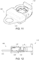
- the removal tool 160 is shown in FIGs. 8-12 .
- the removal tool 160 includes an upper portion 162 and a lower portion 164, which are ultrasonically or similarly coupled together.
- the lower portion 164 includes a pair of spaced apart rails 166 and 168.
- the rails 166, 168 are inserted into slots 170 and 172 in the base plate 119 of the lower housing portion 114 ( FIGs. 1, 3 ).
- Each of the rails 166, 168 has a tapered lead-in portion 166a and 168a, which engages the tabs 138, 139 of movable retaining device 116 and lift the wings 130 and 132 upwardly and out of their seated engagement with the recesses 140, 142. Thereafter, the back end of the tapered lead-in portions 166a, 168a engages the tabs 138, 139.
- the handle 165 on the removal tool 160 is used to pull backward (in the direction of arrow A, FIG. 12 ) so that it moves back in slots 170 and 172 thereby pulling back on retaining device 116, expanding opening 128 and moving fingers 126 away from clamping engagement with the bottle neck 190. Once this is achieved, the removal tool 160 can be removed from the housing assembly 110 and the housing assembly 110 may be lifted from the bottle neck 190 removing the housing assembly 110 therefrom.
- such a removal tool 160 would be employed at the point of purchase such as a checkout counter after the tag housing 110 attached to the bottle 192 is 10 been scanned at the check-out counter and the information contained on the RFID 117 and/or EAS tags 115 is retrieved and/or the alarm is deactivated.
Description
- The present invention relates generally to housings that accommodate electronic tags such as radio frequency identification (RFID) tags or electronic article surveillance (EAS) tags attached to an extending neck of a bottle. More particularly, the present invention relates to a dual component tag housing, which may be securely attached to the extending neck of a bottle and subsequently removed therefrom.
- Electronic tags are used for a wide variety of purposes including the tracking of items that contain the tag, inventory control, security and also provide information that 20 may be electronically readable. These tags or markers may include radio frequency identification (RFID) tags or electronic article surveillance (EAS) tags, which include dual resonator (DR) tags and radio frequency (RF) tags.
- Examples of such tag housings are shown in commonly assigned
U.S. Patent Nos. 8,228,200 ;8,267,326 ; and commonly assignedU.S. Patent Publication Nos. 2010/0133224 and2011/0074583 .US 2009/152230 discloses a bottle security device having the features of the preamble of appended claim 1 and configured to lock onto a bottleneck to prevent theft of the bottle or its content. The bottle security device includes a housing and a cap which receives a portion of the bottleneck and rotates relative to the housing. A locking mechanism is provided to prevent rotation of the cap to keep the device locked on the bottle neck.CN201873118U discloses an antitheft device for a wine bottle, in particular to an antitheft wine bottle label which comprises the shell, an inner ring and a supporting plate which are sequentially sheeted on the neck of the wine bottle from top to bottom. A locking mechanism is arranged on the shell. - As particularly shown in the above incorporated
U.S. Patent No. 8,267,326, issued September 18, 2012 , entitled "Tag for Bottle Neck Having Integral Locking Ring," a tag housing may be attachable to the extending neck of a bottle where the extending neck has an undercut. Flexible fingers supported within the tag housing engage the undercut. The flexible fingers may be tightened onto the bottle neck to secure the tag housing to the bottle neck by use of a surrounding cable tie. The cable tie may be tightened around the flexible fingers to urge the fingers inwardly to securely engage the undercut of the bottle neck. This secures the tag housing to the bottle neck. In order to remove this tag from the bottle neck, the cable tie must be severed releasing the grip of the fingers around the bottle neck. - While this tag housing serves adequately for its intended purposes, removal from the bottle neck after the tag housing has served its purpose is difficult and cumbersome as it must be forcibly removed from the bottle neck. This becomes difficult and time consuming for the user who has purchased the bottle with the tag housing in place. Other tag housings include movable retaining devices, which can be released using a tool so as to permit removal of the housing from the bottle neck. While these tag housings serve adequately for their intended purposes, the ability to remove the housing from the bottle neck requires the housing to be formed of multiple components, which increases the cost of the tag housing.
- The present invention is a tag housing assembly for attaching an electronic tag to an extending neck of a bottle with a perimetrical undercut thereabout. The tag housing assembly includes a tag housing, at least one electronic tag and a retaining device. The tag housing includes a perimetrical exterior side wall extending between a top surface and a base plate to define an interior and an opening extending through the top surface and base plate for receiving the extending neck of the bottle. The at least one electronic tag is located in the interior. The retaining device extends into the opening and defines an adjustable aperture for engaging the extending neck of the bottle. When the tag housing is in a closed position, the retaining device is secured to the neck of the bottle.
- The retaining device can include a plurality of flexible fingers, wherein each flexible finger extends from the base plate to a distal end for surrounding engagement with the neck of the bottle. Preferably, the flexible fingers extend upwardly from the base plate. The retaining device can be either fixedly or movably attached to the base plate so that the adjustable aperture can be increased or decreased to receive a bottle neck inserted through the base plate. After the perimetrical undercut passes through the adjustable aperture, the distal ends of the fingers engage the perimetrical undercut and prevent the tag housing assembly from being removed from the bottle.
- The retaining device includes a first section fixedly attached to the base plate and a second section that is movably attached to the base plate. The movement of the second section changes the size of the adjustable aperture. The tag housing can include a locking mechanism for locking the movable second section of the retaining device in a fixed position. In a preferred embodiment, the second section of the retaining device is movable within the housing interior upon application of a removal tool, which moves the second section to change the size of the adjustable aperture.
- The preferred embodiments of the removable bottle neck tag housing of the present invention, as well as other objects, features and advantages of this invention, will be apparent from the accompanying drawings wherein:
-
FIG. 1 is an exploded, perspective view of the single component tag housing of the first embodiment of the present invention. -
FIGs. 2 and 3 show, respectively, top and bottom perspective views of the assembled housing assembly shown inFIG. 1 . -
FIG. 4 is a sectional view of the assembled housing assembly shown inFIG. 1 secured to a bottle neck. -
FIG. 5 is a top, perspective view of the upper housing portion of the housing assembly shown inFIG. 1 . -
FIG. 6 is a top, perspective view of the movable second section of the retainer device of the first embodiment. -
FIG. 7 is a bottom, perspective view of the lower housing portion of the housing assembly shown inFIG. 1 with the movable section of the retainer device removed. -
FIG. 8 is a perspective view of the removal tool used in combination with the housing assembly shown inFIG. 1 . -
FIG. 9 is an exploded, perspective view of the removal tool shown inFIG. 8 . -
FIG. 10 is a side, sectional view of the removal tool shown inFIG. 8 . -
FIGs. 11 and 12 show, respectively, top, perspective and cross sectional side views 10 of the tool ofFIG. 8 attached to the housing assembly shown inFIG. 1 . - The present invention provides a tag housing assembly for attaching at least one electronic tag to an extending neck of a bottle that can have a perimetrical undercut thereabout. In a first embodiment, the housing assembly includes a housing having an upper housing portion and a lower housing portion defining an interior therebetween. The upper housing portion has a top surface with a perimeter and a side wall extending downwardly from the perimeter. The lower housing portion has a substantially flat base with a bottom surface. A substantially round or oval opening extends from the top surface of the upper housing portion to the bottom surface of the lower housing portion for receiving the extending neck of the bottle. The housing interior accommodates at least one electronic tag. The housing has a fixed retaining device on one side of the opening and a movable retaining device on the opposite side. The fixed and movable retaining devices define an adjustable aperture for accommodation around the neck of a bottle. The movable retaining device is positioned in a clamping position for securing the housing to the neck of the bottle. The movable retaining device is positioned in a release position to remove the housing from the neck of the bottle.
- The tag housing assembly and the different embodiments will now be described with respect to the drawings. In the first embodiment, the
tag housing assembly 110 of the present invention is shown inFIGs. 1-4 . Thetag housing assembly 110 includes anupper housing portion 112, also shown inFIG. 5 ; alower housing portion 114, also shown inFIG. 7 ; and amovable retaining device 116, also shown inFIG. 6 . Theupper housing portion 112 is formed by atop surface 111 and aperimetrical side wall 113 extending downwardly from the edges. Thelower housing portion 114 includes abase plate 119. When assembled as shown inFIGs. 2, 3 and 4 , thehousing assembly 110 supports one or more electronic tags, such as anEAS tag 115 and/or aRFID tag 117, in an interior thereof. Theupper housing portion 112 is joined with thelower housing portion 114 and can be secured thereto using a variety of securement techniques, preferably ultrasonic welding around the peripheral rim thereof. - The upper and
lower housing portions central opening 120 therethrough for accommodation over the extendingneck 190 of abottle 192 with a perimetrical indent 194 (FIG. 3 ). Thelower housing portion 114 includes a fixedretaining device 122 in the form of a plurality of spaced apartflexible fingers 124 extending approximately half way about theopening 120. Thelower housing portion 114 also supports amovable retaining device 116 in the interior ofhousing assembly 110. Themovable retaining device 116 also includes a plurality of spaced apartflexible fingers 126 extending half way about theopening 120. Together theflexible fingers movable retaining devices adjustable aperture 128 for surrounding accommodation of theneck 190 of thebottle 192 extending throughopening 120. - The movable retaining device as shown in
FIG. 6 includes a pair ofwings slots bottom housing portion 114 and moved to a forward position,tabs recesses lower housing portion 114. When seated inlower housing portion 114, themovable retaining device 116 is adjusted so as to move forward towards the fixedretaining device 122 as shown inFIG. 4 whereupon the movable retaining 10device 116 is placed in a clamping position with the fixedretaining device 122 to clamp thehousing assembly 110 to theneck 190 ofbottle 192 beneath undercut 194. Thus, in the clamping position, thehousing assembly 110 is fixedly coupled to theneck 190 of thebottle 192. - In order to remove the housing from its clamped position with the
neck 190 of thebottle 192, a removal tool is employed. Theremoval tool 160 is shown inFIGs. 8-12 . Theremoval tool 160 includes anupper portion 162 and alower portion 164, which are ultrasonically or similarly coupled together. Thelower portion 164 includes a pair of spaced apart rails 166 and 168. Upon placing theremoval tool 160 into engagement with thehousing assembly 110, therails slots base plate 119 of the lower housing portion 114 (FIGs. 1, 3 ). Each of therails portion tabs movable retaining device 116 and lift thewings recesses portions tabs handle 165 on theremoval tool 160 is used to pull backward (in the direction of arrow A,FIG. 12 ) so that it moves back inslots device 116, expandingopening 128 and movingfingers 126 away from clamping engagement with thebottle neck 190. Once this is achieved, theremoval tool 160 can be removed from thehousing assembly 110 and thehousing assembly 110 may be lifted from thebottle neck 190 removing thehousing assembly 110 therefrom. - It is contemplated that such a
removal tool 160 would be employed at the point of purchase such as a checkout counter after thetag housing 110 attached to thebottle 192 is 10 been scanned at the check-out counter and the information contained on theRFID 117 and/orEAS tags 115 is retrieved and/or the alarm is deactivated.
Claims (9)
- A tag housing assembly (110) for attaching an electronic tag (115) to an extending neck (190) of a bottle (192), wherein the neck has a perimetrical undercut (194) thereabout, the tag housing assembly comprising:a tag housing comprising an upper housing portion (112) and a lower housing portion (114), the upper housing portion having a top surface (111) and a perimetrical exterior side wall (113) extending downwardly from edges of the top surface, the lower housing portion (114) having a base (119) wherein the top surface of the upper housing portion (112) and the base of the lower housing portion (114) define an interior and wherein the upper housing portion (112) is configured to be engaged with the lower housing portion (114) and secured thereon;at least one electronic tag (115) disposed in the interior; and characterized in that the top surface of the upper housing portion (112) and the base of the lower housing portion (114) define an opening (120) extending through the top surface and the base for receiving the extending neck (190) of the bottle, and further characterised by a fixed retaining device (122) fixedly attached to the base of the lower housing portion (114) and extending upwardly therefrom, the top surface of the upper housing portion (112) and a movable retaining device (116) configured to be seated in the lower housing portion (114), wherein, when the movable retaining device (116) is seated in the lower housing portion (114), the movable retaining device (116) is adjusted to move forward towards the fixed retaining device (122) to clamp the tag housing assembly (110) to the neck (190) of the bottle (192) beneath the undercut (194),.
- The tag housing assembly of claim 1, wherein, when the tag housing is in a closed position, the fixed and movable retaining devices (122, 116) are secured to the neck of the bottle.
- The tag housing assembly of claim 1, wherein each of the fixed and movable retaining devices (122, 116) comprises a plurality of flexible fingers (124) for surrounding engagement with the neck of the bottle through the opening.
- The tag housing assembly of claim 1, wherein each of the fixed and movable retaining devices (122, 116) includes a plurality of flexible fingers (126) extending half way about the opening (120).
- The tag housing assembly of claim 1, wherein the fixed and movable retaining devices (122, 116) define an adjustable aperture (128) for surrounding engagement with the neck of the bottle through the opening.
- The tag housing assembly of claim 1, wherein the movable retaining device (116) includes a pair of wings (130,132) separated by slots (134, 136).
- The tag housing assembly of claim 6, wherein the wings are flexible such that when the movable retaining device (116) is positioned within the lower housing portion (114) and moved to a forward position, tabs (138, 139) defined on the wings are inserted into recesses (140, 142) formed in the lower housing portion (114).
- The tag housing assembly of claim 1, wherein, when the movable retaining device (116) is seated in the lower housing portion (114), the movable retaining device extends from the base of lower housing portion (114) and into the opening.
- The tag housing assembly of claim 1, wherein the movable retaining device (116) is movable within the interior upon application of a removal tool (160).
Applications Claiming Priority (5)
| Application Number | Priority Date | Filing Date | Title |
|---|---|---|---|
| US201361769917P | 2013-02-27 | 2013-02-27 | |
| US201361769926P | 2013-02-27 | 2013-02-27 | |
| US201361819012P | 2013-05-03 | 2013-05-03 | |
| EP14757059.2A EP2962288B1 (en) | 2013-02-27 | 2014-02-27 | Tag housing assembly for attachment to a bottle neck |
| PCT/US2014/018986 WO2014134292A1 (en) | 2013-02-27 | 2014-02-27 | Tag housing assembly for attachment to a bottle neck |
Related Parent Applications (1)
| Application Number | Title | Priority Date | Filing Date |
|---|---|---|---|
| EP14757059.2A Division EP2962288B1 (en) | 2013-02-27 | 2014-02-27 | Tag housing assembly for attachment to a bottle neck |
Publications (2)
| Publication Number | Publication Date |
|---|---|
| EP3518199A1 EP3518199A1 (en) | 2019-07-31 |
| EP3518199B1 true EP3518199B1 (en) | 2021-01-20 |
Family
ID=51428800
Family Applications (2)
| Application Number | Title | Priority Date | Filing Date |
|---|---|---|---|
| EP14757059.2A Active EP2962288B1 (en) | 2013-02-27 | 2014-02-27 | Tag housing assembly for attachment to a bottle neck |
| EP19157778.2A Active EP3518199B1 (en) | 2013-02-27 | 2014-02-27 | Tag housing assembly for attachment to a bottle neck |
Family Applications Before (1)
| Application Number | Title | Priority Date | Filing Date |
|---|---|---|---|
| EP14757059.2A Active EP2962288B1 (en) | 2013-02-27 | 2014-02-27 | Tag housing assembly for attachment to a bottle neck |
Country Status (5)
| Country | Link |
|---|---|
| US (1) | US9607259B2 (en) |
| EP (2) | EP2962288B1 (en) |
| BR (1) | BR112015020732B1 (en) |
| MX (1) | MX365199B (en) |
| WO (1) | WO2014134292A1 (en) |
Families Citing this family (12)
| Publication number | Priority date | Publication date | Assignee | Title |
|---|---|---|---|---|
| MX2016005158A (en) * | 2013-10-21 | 2016-08-17 | B&G Plastics Inc | Consumer removable tag housing assembly for attachment to a bottle neck. |
| US20170175426A1 (en) * | 2015-12-18 | 2017-06-22 | Checkpoint Systems, Inc. | Anti-impact locking feature |
| USD820441S1 (en) | 2016-06-13 | 2018-06-12 | Integra Lifesciences Nr Ireland Limited | Surgical handpiece nosecone |
| WO2017187345A1 (en) | 2016-04-25 | 2017-11-02 | Integra Lifesciences Nr Ireland Limited | Flue for ultrasonic aspiration surgical horn |
| US20230191017A1 (en) * | 2016-05-20 | 2023-06-22 | Integra Lifesciences Enterprises, Lllp | Ergonomic Tubing Attachment for Medical Apparatus |
| ES2927744T3 (en) | 2016-05-24 | 2022-11-10 | Integra Lifesciences Entpr Lllp | Ergonomic Tube Coupling for Medical Device |
| AU2017362062B2 (en) | 2016-11-16 | 2023-03-23 | Integra Lifesciences Enterprises, Lllp | Ultrasonic surgical handpiece |
| US10687840B1 (en) | 2016-11-17 | 2020-06-23 | Integra Lifesciences Nr Ireland Limited | Ultrasonic transducer tissue selectivity |
| WO2019040643A1 (en) * | 2017-08-23 | 2019-02-28 | Midwest Innovative Products, Llc | Electronic device for attachment to a beverage container |
| US10748051B2 (en) | 2018-06-29 | 2020-08-18 | Intelligent Design Systems Inc. | System and method for attaching identification tags to objects using a flexible attachment device |
| USD1008834S1 (en) * | 2020-01-07 | 2023-12-26 | Carrier Corporation | Snap-on item tracking device |
| DE102020211267A1 (en) | 2020-09-08 | 2022-03-10 | Rapitag Gmbh | locking device |
Family Cites Families (25)
| Publication number | Priority date | Publication date | Assignee | Title |
|---|---|---|---|---|
| MXPA00012968A (en) | 1998-06-24 | 2002-04-24 | Alpha Entpr Inc | Bottle security device. |
| US6696955B2 (en) | 2002-03-05 | 2004-02-24 | B&G Plastics, Inc. | Electronic article surveillance marker and container therewith |
| US6912878B2 (en) | 2003-02-24 | 2005-07-05 | Alpha Security Products, Inc. | Bottle security device |
| EP1678697B1 (en) * | 2003-10-29 | 2008-08-06 | Display Technologies, Inc. | Anti-theft tag |
| US8264350B2 (en) * | 2004-12-07 | 2012-09-11 | Sensormatic Electronics, LLC | Adjustable constraining adaptive insert for merchandise security tag and method thereof |
| ES2380948T3 (en) * | 2004-12-07 | 2012-05-21 | Sensormatic Electronics, LLC | Safety device with a cable |
| US7259674B2 (en) | 2004-12-22 | 2007-08-21 | Alpha Security Products, Inc. | Bottle security device |
| US7262699B2 (en) | 2004-12-30 | 2007-08-28 | Alpha Security Products, Inc. | Security device for cylindrical merchandise |
| EP1940697B1 (en) * | 2005-05-20 | 2009-07-22 | Premier Security Products Limited | Bottle cap protector |
| US7804405B2 (en) | 2005-09-09 | 2010-09-28 | B&G International, Inc. | Tamper-evident bottle overcap for supporting an electronic tag |
| US7394376B1 (en) * | 2005-10-19 | 2008-07-01 | Sayegh Adel O | Theft deterrent tag |
| US7650768B2 (en) * | 2006-01-13 | 2010-01-26 | Checkpoint Systems, Inc. | Bottle security device |
| US7583195B2 (en) | 2006-08-22 | 2009-09-01 | Checkpoint Systems, Inc. | Security tag adapter for containers |
| US7866497B2 (en) * | 2007-12-12 | 2011-01-11 | Checkpoint Systems, Inc. | Bottle security device |
| US8269631B2 (en) * | 2008-02-22 | 2012-09-18 | Xiao Hui Yang | Anti-theft device |
| US8466793B2 (en) | 2008-10-03 | 2013-06-18 | B&G Plastics, Inc. | Electronic tag holder for bottle neck |
| US8228200B2 (en) | 2008-10-03 | 2012-07-24 | B&G Plastics, Inc. | Electronic tag holder for bottle neck |
| US9396670B2 (en) | 2008-12-03 | 2016-07-19 | B&G International, Inc. | Electronic tag holder for capped bottle neck |
| US8432286B2 (en) * | 2008-12-03 | 2013-04-30 | B&G International, Inc. | Electronic tag holder for capped bottle neck |
| US8294583B2 (en) * | 2009-02-27 | 2012-10-23 | Universal Surveillance Corporation | Theft deterrent tag |
| US8525675B2 (en) * | 2010-03-12 | 2013-09-03 | Checkpoint Systems, Inc. | Security device |
| US9311797B2 (en) * | 2010-04-05 | 2016-04-12 | Wg Security Products | EAS tag for bottles |
| WO2012006428A1 (en) * | 2010-07-09 | 2012-01-12 | B&G International Inc. | Tag for bottle neck having integral locking ring |
| US8730046B2 (en) | 2010-10-01 | 2014-05-20 | B&G Plastics, Inc. | EAS integrated faucet tag assembly |
| CN201873118U (en) * | 2010-12-07 | 2011-06-22 | 施建孟 | Antitheft wine bottle label |
-
2014
- 2014-02-27 MX MX2015011033A patent/MX365199B/en active IP Right Grant
- 2014-02-27 EP EP14757059.2A patent/EP2962288B1/en active Active
- 2014-02-27 US US14/768,957 patent/US9607259B2/en active Active
- 2014-02-27 EP EP19157778.2A patent/EP3518199B1/en active Active
- 2014-02-27 BR BR112015020732-4A patent/BR112015020732B1/en active IP Right Grant
- 2014-02-27 WO PCT/US2014/018986 patent/WO2014134292A1/en active Application Filing
Non-Patent Citations (1)
| Title |
|---|
| None * |
Also Published As
| Publication number | Publication date |
|---|---|
| US9607259B2 (en) | 2017-03-28 |
| MX365199B (en) | 2019-05-27 |
| EP2962288B1 (en) | 2019-02-20 |
| EP3518199A1 (en) | 2019-07-31 |
| US20160004951A1 (en) | 2016-01-07 |
| BR112015020732B1 (en) | 2022-01-25 |
| WO2014134292A1 (en) | 2014-09-04 |
| EP2962288A1 (en) | 2016-01-06 |
| BR112015020732A2 (en) | 2017-12-19 |
| EP2962288A4 (en) | 2016-09-28 |
| MX2015011033A (en) | 2016-06-14 |
Similar Documents
| Publication | Publication Date | Title |
|---|---|---|
| EP3518199B1 (en) | Tag housing assembly for attachment to a bottle neck | |
| CA2804935C (en) | Tag for bottle neck having integral locking ring | |
| EP1971739B1 (en) | Bottle security device | |
| US8432286B2 (en) | Electronic tag holder for capped bottle neck | |
| US7464569B2 (en) | Zipper tag housing | |
| US9396670B2 (en) | Electronic tag holder for capped bottle neck | |
| US9576453B2 (en) | Consumer removable tag housing assembly for attachment to a bottle neck | |
| US8466793B2 (en) | Electronic tag holder for bottle neck | |
| EP2084685B1 (en) | Security tag with engaging element | |
| US20030160697A1 (en) | Theft deterrent device | |
| MX2015000558A (en) | Overcap for supporting an electronic tag to a bottle cap. | |
| US20020174695A1 (en) | Theft deterrent tag | |
| EP3132103B1 (en) | Security tag with a magnetic gate | |
| JP2011511993A (en) | Adjustable and constrained adaptive insert for merchandise security tag and method of insertion | |
| RU2635074C2 (en) | Device for prevention of casing with liquid food thefts | |
| US20190099015A1 (en) | Earring security display hanger | |
| US9792792B2 (en) | Security tag for wire handle |
Legal Events
| Date | Code | Title | Description |
|---|---|---|---|
| PUAI | Public reference made under article 153(3) epc to a published international application that has entered the european phase |
Free format text: ORIGINAL CODE: 0009012 |
|
| STAA | Information on the status of an ep patent application or granted ep patent |
Free format text: STATUS: THE APPLICATION HAS BEEN PUBLISHED |
|
| AC | Divisional application: reference to earlier application |
Ref document number: 2962288 Country of ref document: EP Kind code of ref document: P |
|
| AK | Designated contracting states |
Kind code of ref document: A1 Designated state(s): AL AT BE BG CH CY CZ DE DK EE ES FI FR GB GR HR HU IE IS IT LI LT LU LV MC MK MT NL NO PL PT RO RS SE SI SK SM TR |
|
| STAA | Information on the status of an ep patent application or granted ep patent |
Free format text: STATUS: REQUEST FOR EXAMINATION WAS MADE |
|
| 17P | Request for examination filed |
Effective date: 20200129 |
|
| RBV | Designated contracting states (corrected) |
Designated state(s): AL AT BE BG CH CY CZ DE DK EE ES FI FR GB GR HR HU IE IS IT LI LT LU LV MC MK MT NL NO PL PT RO RS SE SI SK SM TR |
|
| GRAP | Despatch of communication of intention to grant a patent |
Free format text: ORIGINAL CODE: EPIDOSNIGR1 |
|
| STAA | Information on the status of an ep patent application or granted ep patent |
Free format text: STATUS: GRANT OF PATENT IS INTENDED |
|
| INTG | Intention to grant announced |
Effective date: 20200803 |
|
| GRAS | Grant fee paid |
Free format text: ORIGINAL CODE: EPIDOSNIGR3 |
|
| GRAA | (expected) grant |
Free format text: ORIGINAL CODE: 0009210 |
|
| STAA | Information on the status of an ep patent application or granted ep patent |
Free format text: STATUS: THE PATENT HAS BEEN GRANTED |
|
| RAP1 | Party data changed (applicant data changed or rights of an application transferred) |
Owner name: B&G INTERNATIONAL PRODUCTS LTD. |
|
| AC | Divisional application: reference to earlier application |
Ref document number: 2962288 Country of ref document: EP Kind code of ref document: P |
|
| AK | Designated contracting states |
Kind code of ref document: B1 Designated state(s): AL AT BE BG CH CY CZ DE DK EE ES FI FR GB GR HR HU IE IS IT LI LT LU LV MC MK MT NL NO PL PT RO RS SE SI SK SM TR |
|
| REG | Reference to a national code |
Ref country code: GB Ref legal event code: FG4D |
|
| REG | Reference to a national code |
Ref country code: CH Ref legal event code: EP |
|
| REG | Reference to a national code |
Ref country code: DE Ref legal event code: R096 Ref document number: 602014074505 Country of ref document: DE |
|
| REG | Reference to a national code |
Ref country code: AT Ref legal event code: REF Ref document number: 1357055 Country of ref document: AT Kind code of ref document: T Effective date: 20210215 |
|
| REG | Reference to a national code |
Ref country code: IE Ref legal event code: FG4D |
|
| REG | Reference to a national code |
Ref country code: NL Ref legal event code: MP Effective date: 20210120 |
|
| REG | Reference to a national code |
Ref country code: LT Ref legal event code: MG9D |
|
| REG | Reference to a national code |
Ref country code: AT Ref legal event code: MK05 Ref document number: 1357055 Country of ref document: AT Kind code of ref document: T Effective date: 20210120 |
|
| PG25 | Lapsed in a contracting state [announced via postgrant information from national office to epo] |
Ref country code: FI Free format text: LAPSE BECAUSE OF FAILURE TO SUBMIT A TRANSLATION OF THE DESCRIPTION OR TO PAY THE FEE WITHIN THE PRESCRIBED TIME-LIMIT Effective date: 20210120 Ref country code: HR Free format text: LAPSE BECAUSE OF FAILURE TO SUBMIT A TRANSLATION OF THE DESCRIPTION OR TO PAY THE FEE WITHIN THE PRESCRIBED TIME-LIMIT Effective date: 20210120 Ref country code: GR Free format text: LAPSE BECAUSE OF FAILURE TO SUBMIT A TRANSLATION OF THE DESCRIPTION OR TO PAY THE FEE WITHIN THE PRESCRIBED TIME-LIMIT Effective date: 20210421 Ref country code: BG Free format text: LAPSE BECAUSE OF FAILURE TO SUBMIT A TRANSLATION OF THE DESCRIPTION OR TO PAY THE FEE WITHIN THE PRESCRIBED TIME-LIMIT Effective date: 20210420 Ref country code: LT Free format text: LAPSE BECAUSE OF FAILURE TO SUBMIT A TRANSLATION OF THE DESCRIPTION OR TO PAY THE FEE WITHIN THE PRESCRIBED TIME-LIMIT Effective date: 20210120 Ref country code: PT Free format text: LAPSE BECAUSE OF FAILURE TO SUBMIT A TRANSLATION OF THE DESCRIPTION OR TO PAY THE FEE WITHIN THE PRESCRIBED TIME-LIMIT Effective date: 20210520 Ref country code: NO Free format text: LAPSE BECAUSE OF FAILURE TO SUBMIT A TRANSLATION OF THE DESCRIPTION OR TO PAY THE FEE WITHIN THE PRESCRIBED TIME-LIMIT Effective date: 20210420 |
|
| PG25 | Lapsed in a contracting state [announced via postgrant information from national office to epo] |
Ref country code: SE Free format text: LAPSE BECAUSE OF FAILURE TO SUBMIT A TRANSLATION OF THE DESCRIPTION OR TO PAY THE FEE WITHIN THE PRESCRIBED TIME-LIMIT Effective date: 20210120 Ref country code: RS Free format text: LAPSE BECAUSE OF FAILURE TO SUBMIT A TRANSLATION OF THE DESCRIPTION OR TO PAY THE FEE WITHIN THE PRESCRIBED TIME-LIMIT Effective date: 20210120 Ref country code: LV Free format text: LAPSE BECAUSE OF FAILURE TO SUBMIT A TRANSLATION OF THE DESCRIPTION OR TO PAY THE FEE WITHIN THE PRESCRIBED TIME-LIMIT Effective date: 20210120 Ref country code: PL Free format text: LAPSE BECAUSE OF FAILURE TO SUBMIT A TRANSLATION OF THE DESCRIPTION OR TO PAY THE FEE WITHIN THE PRESCRIBED TIME-LIMIT Effective date: 20210120 Ref country code: AT Free format text: LAPSE BECAUSE OF FAILURE TO SUBMIT A TRANSLATION OF THE DESCRIPTION OR TO PAY THE FEE WITHIN THE PRESCRIBED TIME-LIMIT Effective date: 20210120 |
|
| REG | Reference to a national code |
Ref country code: DE Ref legal event code: R119 Ref document number: 602014074505 Country of ref document: DE |
|
| PG25 | Lapsed in a contracting state [announced via postgrant information from national office to epo] |
Ref country code: IS Free format text: LAPSE BECAUSE OF FAILURE TO SUBMIT A TRANSLATION OF THE DESCRIPTION OR TO PAY THE FEE WITHIN THE PRESCRIBED TIME-LIMIT Effective date: 20210520 |
|
| REG | Reference to a national code |
Ref country code: BE Ref legal event code: MM Effective date: 20210228 |
|
| PG25 | Lapsed in a contracting state [announced via postgrant information from national office to epo] |
Ref country code: EE Free format text: LAPSE BECAUSE OF FAILURE TO SUBMIT A TRANSLATION OF THE DESCRIPTION OR TO PAY THE FEE WITHIN THE PRESCRIBED TIME-LIMIT Effective date: 20210120 Ref country code: CH Free format text: LAPSE BECAUSE OF NON-PAYMENT OF DUE FEES Effective date: 20210228 Ref country code: CZ Free format text: LAPSE BECAUSE OF FAILURE TO SUBMIT A TRANSLATION OF THE DESCRIPTION OR TO PAY THE FEE WITHIN THE PRESCRIBED TIME-LIMIT Effective date: 20210120 Ref country code: MC Free format text: LAPSE BECAUSE OF FAILURE TO SUBMIT A TRANSLATION OF THE DESCRIPTION OR TO PAY THE FEE WITHIN THE PRESCRIBED TIME-LIMIT Effective date: 20210120 Ref country code: LI Free format text: LAPSE BECAUSE OF NON-PAYMENT OF DUE FEES Effective date: 20210228 Ref country code: LU Free format text: LAPSE BECAUSE OF NON-PAYMENT OF DUE FEES Effective date: 20210227 Ref country code: SM Free format text: LAPSE BECAUSE OF FAILURE TO SUBMIT A TRANSLATION OF THE DESCRIPTION OR TO PAY THE FEE WITHIN THE PRESCRIBED TIME-LIMIT Effective date: 20210120 |
|
| PLBE | No opposition filed within time limit |
Free format text: ORIGINAL CODE: 0009261 |
|
| STAA | Information on the status of an ep patent application or granted ep patent |
Free format text: STATUS: NO OPPOSITION FILED WITHIN TIME LIMIT |
|
| PG25 | Lapsed in a contracting state [announced via postgrant information from national office to epo] |
Ref country code: RO Free format text: LAPSE BECAUSE OF FAILURE TO SUBMIT A TRANSLATION OF THE DESCRIPTION OR TO PAY THE FEE WITHIN THE PRESCRIBED TIME-LIMIT Effective date: 20210120 Ref country code: SK Free format text: LAPSE BECAUSE OF FAILURE TO SUBMIT A TRANSLATION OF THE DESCRIPTION OR TO PAY THE FEE WITHIN THE PRESCRIBED TIME-LIMIT Effective date: 20210120 Ref country code: DK Free format text: LAPSE BECAUSE OF FAILURE TO SUBMIT A TRANSLATION OF THE DESCRIPTION OR TO PAY THE FEE WITHIN THE PRESCRIBED TIME-LIMIT Effective date: 20210120 |
|
| 26N | No opposition filed |
Effective date: 20211021 |
|
| PG25 | Lapsed in a contracting state [announced via postgrant information from national office to epo] |
Ref country code: FR Free format text: LAPSE BECAUSE OF NON-PAYMENT OF DUE FEES Effective date: 20210320 Ref country code: DE Free format text: LAPSE BECAUSE OF NON-PAYMENT OF DUE FEES Effective date: 20210901 Ref country code: AL Free format text: LAPSE BECAUSE OF FAILURE TO SUBMIT A TRANSLATION OF THE DESCRIPTION OR TO PAY THE FEE WITHIN THE PRESCRIBED TIME-LIMIT Effective date: 20210120 Ref country code: IE Free format text: LAPSE BECAUSE OF NON-PAYMENT OF DUE FEES Effective date: 20210227 Ref country code: ES Free format text: LAPSE BECAUSE OF FAILURE TO SUBMIT A TRANSLATION OF THE DESCRIPTION OR TO PAY THE FEE WITHIN THE PRESCRIBED TIME-LIMIT Effective date: 20210120 |
|
| PG25 | Lapsed in a contracting state [announced via postgrant information from national office to epo] |
Ref country code: SI Free format text: LAPSE BECAUSE OF FAILURE TO SUBMIT A TRANSLATION OF THE DESCRIPTION OR TO PAY THE FEE WITHIN THE PRESCRIBED TIME-LIMIT Effective date: 20210120 |
|
| PG25 | Lapsed in a contracting state [announced via postgrant information from national office to epo] |
Ref country code: IT Free format text: LAPSE BECAUSE OF FAILURE TO SUBMIT A TRANSLATION OF THE DESCRIPTION OR TO PAY THE FEE WITHIN THE PRESCRIBED TIME-LIMIT Effective date: 20210120 |
|
| PG25 | Lapsed in a contracting state [announced via postgrant information from national office to epo] |
Ref country code: IS Free format text: LAPSE BECAUSE OF FAILURE TO SUBMIT A TRANSLATION OF THE DESCRIPTION OR TO PAY THE FEE WITHIN THE PRESCRIBED TIME-LIMIT Effective date: 20210520 |
|
| PG25 | Lapsed in a contracting state [announced via postgrant information from national office to epo] |
Ref country code: BE Free format text: LAPSE BECAUSE OF NON-PAYMENT OF DUE FEES Effective date: 20210228 |
|
| PGFP | Annual fee paid to national office [announced via postgrant information from national office to epo] |
Ref country code: GB Payment date: 20230222 Year of fee payment: 10 |
|
| PG25 | Lapsed in a contracting state [announced via postgrant information from national office to epo] |
Ref country code: NL Free format text: LAPSE BECAUSE OF NON-PAYMENT OF DUE FEES Effective date: 20210120 Ref country code: CY Free format text: LAPSE BECAUSE OF FAILURE TO SUBMIT A TRANSLATION OF THE DESCRIPTION OR TO PAY THE FEE WITHIN THE PRESCRIBED TIME-LIMIT Effective date: 20210120 |
|
| PG25 | Lapsed in a contracting state [announced via postgrant information from national office to epo] |
Ref country code: HU Free format text: LAPSE BECAUSE OF FAILURE TO SUBMIT A TRANSLATION OF THE DESCRIPTION OR TO PAY THE FEE WITHIN THE PRESCRIBED TIME-LIMIT; INVALID AB INITIO Effective date: 20140227 |