JP6928627B2 - Insulated wires, cabtyre cables, and how to manufacture them - Google Patents
Insulated wires, cabtyre cables, and how to manufacture them Download PDFInfo
- Publication number
- JP6928627B2 JP6928627B2 JP2019062725A JP2019062725A JP6928627B2 JP 6928627 B2 JP6928627 B2 JP 6928627B2 JP 2019062725 A JP2019062725 A JP 2019062725A JP 2019062725 A JP2019062725 A JP 2019062725A JP 6928627 B2 JP6928627 B2 JP 6928627B2
- Authority
- JP
- Japan
- Prior art keywords
- insulating layer
- mass
- base resin
- silane
- parts
- Prior art date
- Legal status (The legal status is an assumption and is not a legal conclusion. Google has not performed a legal analysis and makes no representation as to the accuracy of the status listed.)
- Active
Links
Images


Landscapes
- Insulated Conductors (AREA)
- Processes Specially Adapted For Manufacturing Cables (AREA)
Description
本発明は、絶縁電線、キャブタイヤケーブル、及びこれらの製造方法に関する。 The present invention relates to insulated electric wires, cabtire cables, and methods for manufacturing these.
絶縁電線は、導体の外周に絶縁層を配したものである。また、キャブタイヤケーブルは、導体の外周にゴム系絶縁層を有する絶縁電線の外周に、シースを配したものであり、シースとして、ゴム系絶縁層に対して機械的強度の大きい、天然ゴムあるいはポリクロロプレンゴム組成物を被覆したものである。キャブタイヤケーブルは、主に建設現場での給電用電線などとして広く使用されている。
絶縁電線又はキャブタイヤケーブルの結線には、通常、絶縁層及び/又はシースを部分的に取り除いて(例えば、端部を取り除いて)、電源や別のケーブル等と電気的に接続させる。しかし、絶縁電線又はキャブタイヤケーブル中の絶縁電線から絶縁層を除去する際に、除去対象部分の絶縁層の一部がむきとれずに導体上に残存し、又は、除去非対象部分の絶縁層の切断端面から延びるひげ(絶縁層を厚さ方向に切断できずに絶縁層の切断端面に残存する(切断端面から延在する)、絶縁層に由来する線状体(毛状体))が生じ、絶縁層の皮むき性に劣る場合や、絶縁層と導体が接着しているために導体自体が伸びてしまう場合があった。そこで、内側絶縁層(いわゆるセパレータ層)を絶縁層の内側に設けることで、絶縁層と導体間の密着の度合いを下げ、絶縁層の皮むき性の改良、導体の延伸を防止する方法が採られてきた。例えば、特許文献1及び特許文献2には、導体上にセパレータ層を有し、その外周を絶縁層で被覆したキャブタイヤケーブルが記載されている。
このセパレータ層としては、例えば、紙、及びポリエチレンテレフタレート等の樹脂を用いた層が使用されてきた。例えば、特許文献3には、セパレータ層として、クロスもしくはフィルムの少なくとも一方の面にゴムコーティングを施した複合テープを用いる技術が提案されている。また、特許文献4には、セパレータ層としてポリエステル製のテープやナイロン製のテープを使用してもよいことが記載されている。
An insulated wire has an insulating layer arranged on the outer circumference of a conductor. Further, the cabtire cable has a sheath arranged on the outer periphery of an insulated wire having a rubber-based insulating layer on the outer periphery of the conductor, and the sheath is made of natural rubber or natural rubber having a higher mechanical strength than the rubber-based insulating layer. It is coated with a polychloroprene rubber composition. Cabtyre cables are widely used mainly as electric wires for power supply at construction sites.
Insulated wires or cabtyre cables are usually connected by partially removing the insulating layer and / or sheath (eg, removing the ends) and electrically connecting to a power source, another cable, or the like. However, when the insulating layer is removed from the insulated wire or the insulated wire in the cabtire cable, a part of the insulating layer of the part to be removed remains on the conductor without being peeled off, or the insulating layer of the part not to be removed is removed. A whiskers extending from the cut end face of the insulating layer (a linear body (hair-like body) derived from the insulating layer, which cannot cut the insulating layer in the thickness direction and remains on the cut end face of the insulating layer (extending from the cut end face)) As a result, the peelability of the insulating layer may be inferior, or the conductor itself may be stretched because the insulating layer and the conductor are adhered to each other. Therefore, by providing an inner insulating layer (so-called separator layer) inside the insulating layer, a method is adopted to reduce the degree of adhesion between the insulating layer and the conductor, improve the peelability of the insulating layer, and prevent the conductor from stretching. Has been done. For example,
As the separator layer, for example, a layer using paper or a resin such as polyethylene terephthalate has been used. For example,
絶縁電線及びキャブタイヤケーブル、特にキャブタイヤケーブルは、配線、特に、工作機器の移動部分の電気的接続に使用され、作業現場などにおいて通電状態のまま移動される。なかでも、多数回にわたって、さらには機械的に、繰り返し屈曲されるような用途に用いられる場合には、絶縁電線及びキャブタイヤケーブルには、高い屈曲耐久性(多数回の屈曲によっても断線しにくい性質)が求められる。
また、上記のようなセパレータ層を有する絶縁電線又はキャブタイヤケーブルについては、皮むきの際に絶縁電線の内側絶縁層(セパレータ層)がむきとれずに導体上に残ってしまう等、絶縁層(2層以上である場合、内側絶縁層の外側に配置される外側絶縁層を含む。)の皮むき性になお改善の余地があった。
Insulated electric wires and cabtire cables, particularly cabtire cables, are used for electrical connection of wiring, particularly moving parts of machine tools, and are moved in an energized state at a work site or the like. In particular, when it is used for applications where it is repeatedly bent over a large number of times, and mechanically, the insulated wire and cabtire cable have high bending durability (it is difficult to break even after a large number of times of bending). Property) is required.
Further, in the case of an insulated wire or cabtire cable having a separator layer as described above, the inner insulating layer (separator layer) of the insulated wire is not peeled off and remains on the conductor when peeled. When there are two or more layers, there is still room for improvement in the peelability of the outer insulating layer arranged outside the inner insulating layer).
本発明は、屈曲耐久性と優れた絶縁層の皮むき性とを兼ね備えた絶縁電線及びキャブタイヤケーブルを提供すること、を課題とする。また、本発明は、上記キャブタイヤケーブル及び絶縁電線の製造方法を提供すること、を課題とする。 An object of the present invention is to provide an insulated electric wire and a cabtire cable having both bending durability and excellent peeling property of an insulating layer. Another object of the present invention is to provide a method for manufacturing the above-mentioned cabtire cable and insulated electric wire.
本発明者らは、導体の外周を被覆する内側絶縁層とその外周を被覆する外側絶縁層とを有する絶縁電線において、内側絶縁層の100%モジュラスを、外側絶縁層の内、最も厚肉な外側絶縁層(厚肉外側絶縁層(Y))の100%のモジュラスより高くし、かつ、厚肉外側絶縁層(Y)を特定のシラン架橋性組成物の硬化物からなる層とすることにより、高い屈曲耐久性及び優れた絶縁層の皮むき性を兼ね備えた絶縁電線とすることができることを見出した。また、これらの高い屈曲耐久性及び優れた絶縁層の皮むき性は、絶縁電線の外周にシースを設けてキャブタイヤケーブルとしても損なわれないことを見出した。本発明者らはこの知見に基づきさらに研究を重ね、本発明をなすに至った。 In an insulated wire having an inner insulating layer covering the outer periphery of a conductor and an outer insulating layer covering the outer periphery thereof, the present inventors make 100% modulus of the inner insulating layer the thickest of the outer insulating layers. By making the outer insulating layer (thick outer insulating layer (Y)) higher than 100% modulus and making the thick outer insulating layer (Y) a layer made of a cured product of a specific silane crosslinkable composition. , It has been found that an insulated wire having both high bending durability and excellent peeling property of an insulating layer can be obtained. Further, it has been found that these high bending durability and the excellent peelability of the insulating layer are not impaired even if a sheath is provided on the outer circumference of the insulated wire to form a cabtire cable. Based on this finding, the present inventors further conducted research and came to the present invention.
すなわち、本発明の課題は以下の手段によって達成された。
〔1〕
導体と、前記導体の外周を被覆する内側絶縁層(X)と、前記内側絶縁層(X)の外周を被覆する少なくとも1層の外側絶縁層とを有する絶縁電線であって、
前記少なくとも1層の外側絶縁層の内、最も厚肉の外側絶縁層(Y)が、下記シラン架橋性組成物(Ay)のシラノール縮合硬化物からなり、
前記内側絶縁層(X)の100%モジュラス(Mx)が前記外側絶縁層(Y)の100%モジュラス(My)より高い、
絶縁電線。
〔シラン架橋性組成物(Ay)〕
エチレンゴム及びスチレン系エラストマーの少なくとも一方を含有するベース樹脂(Ry)100質量部に対して、無機フィラー(Fy)1〜400質量部と、前記ベース樹脂(Ry)とグラフト化反応したシランカップリング剤(Sy)1〜15.0質量部と、シラノール縮合触媒(Cy)とを含有する厚肉のシラン架橋性組成物(Ay)
〔2〕
前記内側絶縁層(X)が下記シラン架橋性組成物(Ax)のシラノール縮合硬化物からなる、〔1〕に記載の絶縁電線。
〔シラン架橋性組成物(Ax)〕
ベース樹脂(Rx)100質量部に対して、無機フィラー(Fx)1〜400質量部と、前記ベース樹脂(Rx)とグラフト化反応したシランカップリング剤(Sx)1〜15.0質量部と、シラノール縮合触媒(Cx)とを含有するシラン架橋性組成物(Ax)
〔3〕
前記ベース樹脂(Rx)中のエチレンゴム、スチレン系エラストマー、及び非芳香族有機油の合計含有量が、前記ベース樹脂(Ry)中のエチレンゴム、スチレン系エラストマー、及び非芳香族有機油の合計含有量よりも少ない、請求項2に記載の絶縁電線。
〔4〕
絶縁電線の外周をシースで被覆してなるキャブタイヤケーブルであって、
前記絶縁電線が、導体と、前記導体の外周を被覆する内側絶縁層(X)と、前記内側絶縁層(X)の外周を被覆する少なくとも1層の外側絶縁層とを有し、
前記少なくとも1層の外側絶縁層の内、最も厚肉の外側絶縁層(Y)が、下記シラン架橋性組成物(Ay)のシラノール縮合硬化物からなり、
前記内側絶縁層(X)の100%モジュラス(Mx)が前記外側絶縁層(Y)の100%モジュラス(My)より高い、
キャブタイヤケーブル。
〔シラン架橋性組成物(Ay)〕
エチレンゴム及びスチレン系エラストマーの少なくとも一方を含有するベース樹脂(Ry)100質量部に対して、無機フィラー(Fy)1〜400質量部と、前記ベース樹脂(Ry)とグラフト化反応したシランカップリング剤(Sy)1〜15.0質量部と、シラノール縮合触媒(Cy)とを含有するシラン架橋性組成物(Ay)
〔5〕
前記内側絶縁層(X)が下記シラン架橋性組成物(Ax)のシラノール縮合硬化物からなる、〔3〕に記載のキャブタイヤケーブル。
〔シラン架橋性組成物(Ax)〕
ベース樹脂(Rx)100質量部に対して、無機フィラー(Fx)1〜400質量部と、前記ベース樹脂(Rx)とグラフト化反応したシランカップリング剤(Sx)1〜15.0質量部と、シラノール縮合触媒(Cx)とを含有するシラン架橋性組成物(Ax)
〔6〕
前記ベース樹脂(Rx)中のエチレンゴム、スチレン系エラストマー、及び非芳香族有機油の合計含有量が、前記ベース樹脂(Ry)中のエチレンゴム、スチレン系エラストマー、及び非芳香族有機油の合計含有量よりも少ない、〔5〕に記載のキャブタイヤケーブル。
〔7〕
前記シースが、下記シラン架橋性組成物(Az)のシラノール縮合硬化物からなる、〔4〕〜〔6〕のいずれか1項に記載のキャブタイヤケーブル。
〔シラン架橋性組成物(Az)〕
含ハロゲン樹脂を含有するベース樹脂(Rz)100質量部に対して、無機フィラー(Fz)1〜200質量部と、前記ベース樹脂(Rz)とグラフト化反応したシランカップリング剤(Sz)2質量部を越え15.0質量部以下と、シラノール縮合触媒(Cz)とを含有するシラン架橋性組成物(Az)
〔8〕
前記ベース樹脂(Rz)が、塩素化ポリエチレンとポリ塩化ビニルと可塑剤とを含有する〔7〕に記載のキャブタイヤケーブル。
〔9〕
導体と、前記導体の外周を被覆する内側絶縁層(X)と、前記内側絶縁層(X)の外周を被覆する少なくとも1層の外側絶縁層とを有し、前記少なくとも1層の外側絶縁層が最も厚肉の外側絶縁層(Y)を有し、前記内側絶縁層(X)の100%モジュラス(Mx)が前記外側絶縁層(Y)の100%モジュラス(My)より高い、絶縁電線の製造方法であって、
前記外側絶縁層(Y)を、下記工程(e)〜(h)により形成する、絶縁電線の製造方法。
工程(e):エチレンゴム及びスチレン系エラストマーの少なくとも一方を含有するベース樹脂(Ry)100質量部に対して、有機過酸化物(Py)0.01〜0.6質量部と、無機フィラー(Fy)1〜400質量部と、前記ベース樹脂(Ry)とグラフト化反応しうるグラフト化反応部位を有するシランカップリング剤(Sy)1〜15.0質量部とを溶融混合して、前記グラフト化反応部位と前記ベース樹脂(Ry)とをグラフト化反応させることにより、シラン架橋性樹脂(Ly)を含むシランマスターバッチ(Iy)を調製する工程
工程(f):前記シランマスターバッチ(Iy)及びシラノール縮合触媒(Cy)を溶融混合してシラン架橋性組成物(Ay)を得る工程
工程(g):前記シラン架橋性組成物(Ay)で前記内側絶縁層(X)の外周を被覆して外側絶縁層前駆体(By)を形成する工程
工程(h):前記外側絶縁層前駆体(By)を水と接触させて前記外側絶縁層(Y)を形成する工程
〔10〕
前記ベース樹脂(Ry)の一部を前記工程(e)において溶融混合し、前記ベース樹脂(Ry)の残部を前記工程(f)において混合する、〔9〕に記載の絶縁電線の製造方法。
〔11〕
前記内側絶縁層(X)を、下記工程(a)〜(d)により形成する、〔9〕又は〔10〕に記載の絶縁電線の製造方法。
工程(a):ベース樹脂(Rx)100質量部に対して、有機過酸化物(Px)0.01〜0.6質量部と、無機フィラー(Fx)1〜400質量部と、前記ベース樹脂(Rx)とグラフト化反応しうるグラフト化反応部位を有するシランカップリング剤(Sx)1〜15.0質量部とを溶融混合して、前記グラフト化反応部位と前記ベース樹脂(Rx)とをグラフト化反応させることにより、シラン架橋性樹脂(Lx)を含むシランマスターバッチ(Ix)を調製する工程
工程(b):前記シランマスターバッチ(Ix)及びシラノール縮合触媒(Cx)を溶融混合してシラン架橋性組成物(Ax)を得る工程
工程(c):前記シラン架橋性組成物(Ax)で前記導体の外周を被覆して内側絶縁層前駆体を形成する工程
工程(d):前記内側絶縁層前駆体を水と接触させて前記内側絶縁層(X)を形成する工程
〔12〕
前記ベース樹脂(Rx)の一部を前記工程(a)において溶融混合し、前記ベース樹脂(Rx)の残部を前記工程(b)において混合する、〔11〕に記載の絶縁電線の製造方法。
〔13〕
絶縁電線の外周をシースで被覆してなり、前記絶縁電線が、導体と、前記導体の外周を被覆する内側絶縁層(X)と、前記内側絶縁層(X)の外周を被覆する少なくとも1層の外側絶縁層とを有し、前記少なくとも1層の外側絶縁層が最も厚肉の外側絶縁層(Y)を有し、前記内側絶縁層(X)の100%モジュラス(Mx)が前記外側絶縁層(Y)の100%モジュラス(My)より高い、キャブタイヤケーブルの製造方法であって、
前記外側絶縁層(Y)を、下記工程(e)〜(h)により形成する、キャブタイヤケーブルの製造方法。
工程(e):エチレンゴム及びスチレン系エラストマーの少なくとも一方を含有するベース樹脂(Ry)100質量部に対して、有機過酸化物(Py)0.01〜0.6質量部と、無機フィラー(Fy)1〜400質量部と、前記ベース樹脂(Ry)とグラフト化反応しうるグラフト化反応部位を有するシランカップリング剤(Sy)1〜15.0質量部とを溶融混合して、前記グラフト化反応部位と前記ベース樹脂(Ry)とをグラフト化反応させることにより、シラン架橋性樹脂(Ly)を含むシランマスターバッチ(Iy)を調製する工程
工程(f):前記シランマスターバッチ(Iy)及びシラノール縮合触媒(Cy)を溶融混合してシラン架橋性組成物(Ay)を得る工程
工程(g):前記シラン架橋性組成物(Ay)で前記内側絶縁層(X)の外周を被覆して外側絶縁層前駆体(By)を形成する工程
工程(h):前記外側絶縁層前駆体(By)を水と接触させて前記外側絶縁層(Y)を形成する工程
〔14〕
前記ベース樹脂(Ry)の一部を前記工程(e)において溶融混合し、前記ベース樹脂(Ry)の残部を前記工程(f)において混合する、〔13〕に記載のキャブタイヤケーブルの製造方法。
〔15〕
前記内側絶縁層(X)を、下記工程(a)〜(d)により形成する、〔13〕又は〔14〕に記載のキャブタイヤケーブルの製造方法。
工程(a):ベース樹脂(Rx)100質量部に対して、有機過酸化物(Px)0.01〜0.6質量部と、無機フィラー(Fx)1〜400質量部と、前記ベース樹脂(Rx)とグラフト化反応しうるグラフト化反応部位を有するシランカップリング剤(Sx)1〜15.0質量部とを溶融混合して、前記グラフト化反応部位と前記ベース樹脂(Rx)とをグラフト化反応させることにより、シラン架橋性樹脂(Lx)を含むシランマスターバッチ(Ix)を調製する工程
工程(b):前記シランマスターバッチ(Ix)及びシラノール縮合触媒(Cx)を溶融混合してシラン架橋性組成物(Ax)を得る工程
工程(c):前記シラン架橋性組成物(Ax)で前記導体の外周を被覆して内側絶縁層前駆体を形成する工程
工程(d):前記内側絶縁層前駆体を水と接触させて前記内側絶縁層(X)を形成する工程
〔16〕
前記ベース樹脂(Rx)の一部を前記工程(a)において溶融混合し、前記ベース樹脂(Rx)の残部を前記工程(b)において混合する、〔15〕に記載のキャブタイヤケーブルの製造方法。
〔17〕
前記シースを下記工程(k)〜(n)により形成する、〔13〕〜〔16〕のいずれか1項に記載のキャブタイヤケーブルの製造方法。
工程(k):含ハロゲン樹脂を含有するベース樹脂(Rz)100質量部に対して、有機過酸化物(Pz)0.003〜0.3質量部と、無機フィラー(Fz)1〜200質量部と、前記ベース樹脂(Rz)とグラフト化反応しうるグラフト化反応部位を有するシランカップリング剤(Sz)2質量部を越え15.0質量部以下とを溶融混合して、前記グラフト化反応部位と前記ベース樹脂(Rz)とをグラフト化反応させることにより、シラン架橋性樹脂(Lz)を含むシランマスターバッチ(Iz)を調製する工程
工程(l):前記シランマスターバッチ(Iz)とシラノール縮合触媒(Cz)とを溶融混合してシラン架橋性組成物(Az)を得る工程
工程(m):前記シラン架橋性組成物(Az)で、前記絶縁電線の外周を被覆してシース前駆体を形成する工程
工程(n):前記シース前駆体を水分と接触させて前記シースを形成する工程
〔18〕
前記ベース樹脂(Rz)の一部を前記工程(k)において溶融混合し、前記ベース樹脂(Rz)の残部を前記工程(l)において混合する、〔17〕に記載のキャブタイヤケーブルの製造方法。
〔19〕
前記ベース樹脂(Rz)の残部にクロロプレンゴムを含有する、〔17〕又は〔18〕のいずれか1項に記載のキャブタイヤケーブルの製造方法。
That is, the subject of the present invention has been achieved by the following means.
[1]
An insulated wire having a conductor, an inner insulating layer (X) covering the outer circumference of the conductor, and at least one outer insulating layer covering the outer circumference of the inner insulating layer (X).
Of the at least one outer insulating layer, the thickest outer insulating layer (Y) is composed of a silanol condensed cured product of the following silane crosslinkable composition (Ay).
The 100% modulus (Mx) of the inner insulating layer (X) is higher than the 100% modulus (My) of the outer insulating layer (Y).
Insulated wire.
[Silane crosslinkable composition (Ay)]
Silane coupling of 1 to 400 parts by mass of an inorganic filler (Fy) and a graft reaction with the base resin (Ry) with respect to 100 parts by mass of a base resin (Ry) containing at least one of an ethylene rubber and a styrene-based elastomer. A thick silane crosslinkable composition (Ay) containing 1 to 15.0 parts by mass of an agent (Sy) and a silanol condensation catalyst (Cy).
[2]
The insulated wire according to [1], wherein the inner insulating layer (X) is made of a silanol condensed cured product of the following silane crosslinkable composition (Ax).
[Silane crosslinkable composition (Ax)]
1 to 400 parts by mass of the inorganic filler (Fx) and 1 to 15.0 parts by mass of the silane coupling agent (Sx) grafted with the base resin (Rx) with respect to 100 parts by mass of the base resin (Rx). , Silane crosslinkable composition (Ax) containing silanol condensation catalyst (Cx).
[3]
The total content of ethylene rubber, styrene-based elastomer, and non-aromatic organic oil in the base resin (Rx) is the total of ethylene rubber, styrene-based elastomer, and non-aromatic organic oil in the base resin (Ry). The insulated wire according to
[4]
A cabtire cable in which the outer circumference of an insulated wire is covered with a sheath.
The insulated wire has a conductor, an inner insulating layer (X) that covers the outer circumference of the conductor, and at least one outer insulating layer that covers the outer circumference of the inner insulating layer (X).
Of the at least one outer insulating layer, the thickest outer insulating layer (Y) is composed of a silanol condensed cured product of the following silane crosslinkable composition (Ay).
The 100% modulus (Mx) of the inner insulating layer (X) is higher than the 100% modulus (My) of the outer insulating layer (Y).
Cabtyre cable.
[Silane crosslinkable composition (Ay)]
Silane coupling of 1 to 400 parts by mass of an inorganic filler (Fy) and a graft reaction with the base resin (Ry) with respect to 100 parts by mass of a base resin (Ry) containing at least one of an ethylene rubber and a styrene-based elastomer. A silane crosslinkable composition (Ay) containing 1 to 15.0 parts by mass of an agent (Sy) and a silanol condensation catalyst (Cy).
[5]
The cabtire cable according to [3], wherein the inner insulating layer (X) is made of a silanol condensed cured product of the following silane crosslinkable composition (Ax).
[Silane crosslinkable composition (Ax)]
1 to 400 parts by mass of the inorganic filler (Fx) and 1 to 15.0 parts by mass of the silane coupling agent (Sx) grafted with the base resin (Rx) with respect to 100 parts by mass of the base resin (Rx). , Silane crosslinkable composition (Ax) containing silanol condensation catalyst (Cx).
[6]
The total content of ethylene rubber, styrene-based elastomer, and non-aromatic organic oil in the base resin (Rx) is the total of ethylene rubber, styrene-based elastomer, and non-aromatic organic oil in the base resin (Ry). The cabtire cable according to [5], which is less than the content.
[7]
The cabtire cable according to any one of [4] to [6], wherein the sheath is made of a silanol condensed cured product of the following silane crosslinkable composition (Az).
[Silane crosslinkable composition (Az)]
1 to 200 parts by mass of an inorganic filler (Fz) and 2 parts by mass of a silane coupling agent (Sz) grafted with the base resin (Rz) with respect to 100 parts by mass of a base resin (Rz) containing a halogen-containing resin. A silane crosslinkable composition (Az) containing 15.0 parts by mass or less and a silanol condensation catalyst (Cz).
[8]
The cabtire cable according to [7], wherein the base resin (Rz) contains chlorinated polyethylene, polyvinyl chloride, and a plasticizer.
[9]
It has a conductor, an inner insulating layer (X) that covers the outer periphery of the conductor, and at least one outer insulating layer that covers the outer periphery of the inner insulating layer (X), and the outer insulating layer of at least one layer. Has the thickest outer insulating layer (Y), and the 100% modulus (Mx) of the inner insulating layer (X) is higher than the 100% modulus (My) of the outer insulating layer (Y). It ’s a manufacturing method,
A method for manufacturing an insulated electric wire, wherein the outer insulating layer (Y) is formed by the following steps (e) to (h).
Step (e): With respect to 100 parts by mass of the base resin (Ry) containing at least one of ethylene rubber and a styrene-based elastomer, 0.01 to 0.6 parts by mass of the organic peroxide (Py) and an inorganic filler ( Fy) 1 to 400 parts by mass and 1 to 15.0 parts by mass of a silane coupling agent (Sy) having a grafting reaction site capable of crosslinking with the base resin (Ry) are melt-mixed and the graft Step of preparing a silane master batch (Iy) containing a silane crosslinkable resin (Ly) by grafting a chemical reaction site with the base resin (Ry) Step (f): The silane master batch (Iy) And a step of melt-mixing the silanol condensation catalyst (Cy) to obtain a silane crosslinkable composition (Ay) Step (g): The outer periphery of the inner insulating layer (X) is coated with the silane crosslinkable composition (Ay). Step (h): Step of contacting the outer insulating layer precursor (By) with water to form the outer insulating layer (Y) [10]
The method for producing an insulated wire according to [9], wherein a part of the base resin (Ry) is melt-mixed in the step (e) and the rest of the base resin (Ry) is mixed in the step (f).
[11]
The method for manufacturing an insulated electric wire according to [9] or [10], wherein the inner insulating layer (X) is formed by the following steps (a) to (d).
Step (a): With respect to 100 parts by mass of the base resin (Rx), 0.01 to 0.6 parts by mass of the organic peroxide (Px), 1 to 400 parts by mass of the inorganic filler (Fx), and the base resin. (Rx) and 1 to 15.0 parts by mass of a silane coupling agent (Sx) having a grafting reaction site capable of a grafting reaction are melt-mixed to obtain the grafting reaction site and the base resin (Rx). Step of preparing a silane master batch (Ix) containing a silane crosslinkable resin (Lx) by performing a grafting reaction Step (b): The silane master batch (Ix) and the silanol condensation catalyst (Cx) are melt-mixed. Step of obtaining a silane crosslinkable composition (Ax) Step (c): Step of covering the outer periphery of the conductor with the silane crosslinkable composition (Ax) to form an inner insulating layer precursor Step (d): The inner side Step of contacting the insulating layer precursor with water to form the inner insulating layer (X) [12]
The method for manufacturing an insulated wire according to [11], wherein a part of the base resin (Rx) is melt-mixed in the step (a) and the rest of the base resin (Rx) is mixed in the step (b).
[13]
The outer periphery of the insulated wire is covered with a sheath, and the insulated wire covers a conductor, an inner insulating layer (X) that covers the outer periphery of the conductor, and at least one layer that covers the outer periphery of the inner insulating layer (X). The outer insulating layer of at least one layer has the thickest outer insulating layer (Y), and the 100% modulus (Mx) of the inner insulating layer (X) is the outer insulating layer. A method of manufacturing a cabtyre cable that is higher than the 100% modulus (My) of the layer (Y).
A method for manufacturing a cabtire cable, wherein the outer insulating layer (Y) is formed by the following steps (e) to (h).
Step (e): With respect to 100 parts by mass of the base resin (Ry) containing at least one of ethylene rubber and a styrene-based elastomer, 0.01 to 0.6 parts by mass of the organic peroxide (Py) and an inorganic filler ( Fy) 1 to 400 parts by mass and 1 to 15.0 parts by mass of a silane coupling agent (Sy) having a grafting reaction site capable of crosslinking with the base resin (Ry) are melt-mixed and the graft Step of preparing a silane master batch (Iy) containing a silane crosslinkable resin (Ly) by grafting a chemical reaction site with the base resin (Ry) Step (f): The silane master batch (Iy) And a step of melt-mixing the silanol condensation catalyst (Cy) to obtain a silane crosslinkable composition (Ay) Step (g): The outer periphery of the inner insulating layer (X) is coated with the silane crosslinkable composition (Ay). Step (h): Step of contacting the outer insulating layer precursor (By) with water to form the outer insulating layer (Y) [14]
The method for manufacturing a cabtire cable according to [13], wherein a part of the base resin (Ry) is melt-mixed in the step (e) and the rest of the base resin (Ry) is mixed in the step (f). ..
[15]
The method for manufacturing a cabtire cable according to [13] or [14], wherein the inner insulating layer (X) is formed by the following steps (a) to (d).
Step (a): With respect to 100 parts by mass of the base resin (Rx), 0.01 to 0.6 parts by mass of the organic peroxide (Px), 1 to 400 parts by mass of the inorganic filler (Fx), and the base resin. (Rx) and 1 to 15.0 parts by mass of a silane coupling agent (Sx) having a grafting reaction site capable of a grafting reaction are melt-mixed to obtain the grafting reaction site and the base resin (Rx). Step of preparing a silane master batch (Ix) containing a silane crosslinkable resin (Lx) by performing a grafting reaction Step (b): The silane master batch (Ix) and the silanol condensation catalyst (Cx) are melt-mixed. Step of obtaining a silane crosslinkable composition (Ax) Step (c): Step of covering the outer periphery of the conductor with the silane crosslinkable composition (Ax) to form an inner insulating layer precursor Step (d): The inner side Step of contacting the insulating layer precursor with water to form the inner insulating layer (X) [16]
The method for manufacturing a cabtire cable according to [15], wherein a part of the base resin (Rx) is melt-mixed in the step (a) and the rest of the base resin (Rx) is mixed in the step (b). ..
[17]
The method for manufacturing a cabtire cable according to any one of [13] to [16], wherein the sheath is formed by the following steps (k) to (n).
Step (k): 0.003 to 0.3 parts by mass of organic peroxide (Pz) and 1 to 200 parts by mass of inorganic filler (Fz) with respect to 100 parts by mass of the base resin (Rz) containing the halogen-containing resin. The grafting reaction is carried out by melt-mixing a portion and 15.0 parts by mass or less of a silane coupling agent (Sz) having a grafting reaction site capable of performing a grafting reaction with the base resin (Rz). Step of preparing a silane masterbatch (Iz) containing a silane crosslinkable resin (Lz) by grafting a site with the base resin (Rz) Step (l): The silane masterbatch (Iz) and silanol Step of melt-mixing with a condensation catalyst (Cz) to obtain a silane crosslinkable composition (Az) Step (m): The sheath precursor is coated on the outer periphery of the insulated wire with the silane crosslinkable composition (Az). Step (n): A step of bringing the sheath precursor into contact with water to form the sheath [18].
The method for manufacturing a cabtire cable according to [17], wherein a part of the base resin (Rz) is melt-mixed in the step (k) and the rest of the base resin (Rz) is mixed in the step (l). ..
[19]
The method for manufacturing a cabtire cable according to any one of [17] and [18], wherein the chloroprene rubber is contained in the remainder of the base resin (Rz).
本明細書において「〜」を用いて表される数値範囲は、「〜」前後に記載される数値を下限値及び上限値として含む範囲を意味する。 The numerical range represented by using "~" in the present specification means a range including the numerical values before and after "~" as the lower limit value and the upper limit value.
本発明の絶縁電線及びキャブタイヤケーブルは、屈曲耐久性及び絶縁層の皮むき性に優れる。さらに、本発明の絶縁電線の製造方法及びキャブタイヤケーブルの製造方法によれば、上記優れた特性を有する、絶縁電線及びキャブタイヤケーブルを製造することができる。 The insulated wire and cabtire cable of the present invention are excellent in bending durability and peeling property of the insulating layer. Further, according to the method for manufacturing an insulated wire and the method for manufacturing a cabtire cable of the present invention, it is possible to manufacture an insulated wire and a cabtire cable having the above-mentioned excellent characteristics.
〔〔絶縁電線〕〕
本発明の絶縁電線は、導体と、導体の外周を被覆する内側絶縁層(X)と、内側絶縁層(X)の外周を被覆する少なくとも1層の外側絶縁層とを有し、少なくとも1層の外側絶縁層の内、最も厚肉の外側絶縁層(Y)(以下、厚肉外側絶縁層(Y)ともいう)が、下記シラン架橋性組成物(Ay)のシラノール縮合硬化物からなり、内側絶縁層(X)の100%モジュラスが厚肉外側絶縁層(Y)の100%モジュラスより高い。
絶縁電線の構成は、上記以外は特に限定されず、通常の絶縁電線の構成とすることができる。
[[Insulated wire]]
The insulated wire of the present invention has a conductor, an inner insulating layer (X) that covers the outer periphery of the conductor, and at least one outer insulating layer that covers the outer periphery of the inner insulating layer (X), and has at least one layer. The thickest outer insulating layer (Y) (hereinafter, also referred to as the thick outer insulating layer (Y)) is composed of the silanol condensation cured product of the following silane crosslinkable composition (Ay). The 100% modulus of the inner insulating layer (X) is higher than the 100% modulus of the thick outer insulating layer (Y).
The configuration of the insulated wire is not particularly limited except for the above, and a normal insulated wire configuration can be used.
本発明の絶縁電線において、内側絶縁層(X)の100%モジュラス(Mx)は、厚肉外側絶縁層(Y)の100%モジュラス(My)より高い(Mx>My)。この関係を満たすと、高い屈曲耐久性及び優れた絶縁層の皮むき性を絶縁電線、ひいてはキャブタイヤケーブルに付与することができる。
ここで、100%モジュラスは、JIS C 3005 法に準拠する、後述する実施例の測定方法により測定された値とする。
内側絶縁層(X)の100%モジュラス(Mx)は、厚肉外側絶縁層(Y)の100%モジュラス(My)に対して、0.5〜20.0MPa高いことが好ましく、1.0〜20.0MPa高いことがより好ましく、3.0〜14.0MPa高いことがさらに好ましい。上記範囲内とすると、より高い屈曲耐久性を絶縁電線等に付与することができる。
内側絶縁層(X)の100%モジュラス(Mx)は、5.0〜28.0MPaが好ましく、7.0〜22.0MPaがより好ましく、8.0〜18.0MPaがさらに好ましく、10.0〜18.0MPaが特に好ましい。
厚肉外側絶縁層(Y)の100%モジュラス(My)は、1.2〜8.0MPaが好ましく、2.0〜6.5MPaがより好ましい。
上記内側絶縁層の100%モジュラス(Mx)及び外側絶縁層の100%モジュラス(My)は、樹脂成分の種類及び含有量、無機フィラーの種類及び含有量、架橋の度合い等を調整することにより上記範囲に設定することができる。
絶縁電線が複数の外側絶縁層を有する場合、厚肉外側絶縁層(Y)以外の外側絶縁層の100%モジュラスは、内側絶縁層(X)の100%モジュラス(Mx)よりも低ければ、特に限定されず、厚肉外側絶縁層(Y)の100%モジュラス(My)と同じでも、低くても、高くてもよい。
In the insulated wire of the present invention, the 100% modulus (Mx) of the inner insulating layer (X) is higher (Mx> My) than the 100% modulus (My) of the thick outer insulating layer (Y). When this relationship is satisfied, high bending durability and excellent peeling property of the insulating layer can be imparted to the insulated wire and, by extension, the cabtire cable.
Here, the 100% modulus is a value measured by the measuring method of Examples described later, which conforms to the JIS C 3005 method.
The 100% modulus (Mx) of the inner insulating layer (X) is preferably 0.5 to 20.0 MPa higher than the 100% modulus (My) of the thick outer insulating layer (Y), and is preferably 1.0 to 20.0 MPa. It is more preferably 20.0 MPa higher, and even more preferably 3.0 to 14.0 MPa higher. Within the above range, higher bending durability can be imparted to the insulated wire or the like.
The 100% modulus (Mx) of the inner insulating layer (X) is preferably 5.0 to 28.0 MPa, more preferably 7.0 to 22.0 MPa, even more preferably 8.0 to 18.0 MPa, 10.0. ~ 18.0 MPa is particularly preferable.
The 100% modulus (My) of the thick outer insulating layer (Y) is preferably 1.2 to 8.0 MPa, more preferably 2.0 to 6.5 MPa.
The 100% modulus (Mx) of the inner insulating layer and the 100% modulus (My) of the outer insulating layer can be obtained by adjusting the type and content of the resin component, the type and content of the inorganic filler, the degree of cross-linking, and the like. Can be set to a range.
Especially when the insulated wire has a plurality of outer insulating layers, the 100% modulus of the outer insulating layer other than the thick outer insulating layer (Y) is lower than the 100% modulus (Mx) of the inner insulating layer (X). It is not limited, and may be the same as, lower, or higher than the 100% modulus (My) of the thick outer insulating layer (Y).
本発明において、外周を直接被覆するとは、導体の外周面に接した状態に所定の層を設けることを意味し、換言すると、外周面と所定の層との間に他の層や構造物が介在していないことを意味する。また、外周を被覆するとは、外周を直接被覆する態様と、外周を他の層又は部材を介して間接被覆する態様との両態様を包含する。 In the present invention, directly covering the outer circumference means providing a predetermined layer in contact with the outer peripheral surface of the conductor, in other words, another layer or structure is provided between the outer peripheral surface and the predetermined layer. It means that there is no intervention. Further, covering the outer circumference includes both a mode of directly covering the outer circumference and a mode of indirectly covering the outer circumference via another layer or member.
絶縁電線中の導体は、1本でもよく、複数本でもよい。複数本である場合には、撚りあわされ、もしくは並べられて、集合体を形成していることが好ましい。導体としては、絶縁電線に通常用いられるものを特に制限されずに用いることができ、軟銅の単線又は撚り線等を用いることができる。また、導体としては銅、銅合金、アルミ、アルミ合金などの裸線の他に、錫メッキしたものやエナメル被覆を有するものを用いることもできる。導体の外径は、用途等に応じて適宜に設定することができる。 The number of conductors in the insulated wire may be one or a plurality. In the case of a plurality of pieces, it is preferable that they are twisted or arranged to form an aggregate. As the conductor, those usually used for an insulated electric wire can be used without particular limitation, and a single wire or a stranded wire of annealed copper can be used. Further, as the conductor, in addition to bare wires such as copper, copper alloy, aluminum, and aluminum alloy, tin-plated conductors and conductors having an enamel coating can also be used. The outer diameter of the conductor can be appropriately set according to the application and the like.
内側絶縁層(X)は導体の外周を被覆する。内側絶縁層は、導体の外周を直接被覆していることが好ましいが、本発明の効果を損なわない範囲で介在物を有していてもよい。内側絶縁層(X)が導体の外周を被覆する態様は、複数本の導体の集合体を用いる場合には、一体となった集合体の外周を被覆していればよく、集合体を形成する各導体の外周を覆っている必要はない。また、内側絶縁層(X)は、導体との間に、一部空間を有するように配されていてもよい。すなわち、導体又は集合体の外周面が凹凸を有する場合には、内側絶縁層(X)は凹凸形状に追従して(凹凸表面に接して)いなくてもよい。
内側絶縁層(X)の厚さは、用途等に応じて適宜に決定することができる。例えば、内側絶縁層(X)の平均厚さは、好ましくは0.1〜0.5mmであり、より好ましくは0.5〜0.4mmである。ここで、内側絶縁層(X)の平均厚さは、絶縁電線から導体を引き抜いて得られた管状片の、管状片の軸線に対して垂直な任意の断面を顕微鏡で観察した際の、任意の点を起点(0度)として、周方向に、中心角0度、90度、180度、及び270度の4箇所で測定された厚さの平均値である。また、複数本の導体の集合体を用いる場合には、上記任意の断面において、内側絶縁層(X)の厚さが最も薄い部分を起点として、周方向に、中心角0度、90度、180度、及び270度の4箇所で測定した厚さの平均値である。
内側絶縁層(X)は、通常の絶縁層として機能すればよく、さらに、いわゆるセパレータとして、導体と外側絶縁層との密着性を制御する機能を有する層として機能してもよい。
The inner insulating layer (X) covers the outer circumference of the conductor. The inner insulating layer preferably directly covers the outer circumference of the conductor, but may have inclusions as long as the effects of the present invention are not impaired. In the mode in which the inner insulating layer (X) covers the outer periphery of the conductor, when an aggregate of a plurality of conductors is used, it suffices to cover the outer circumference of the integrated aggregate to form the aggregate. It is not necessary to cover the outer circumference of each conductor. Further, the inner insulating layer (X) may be arranged so as to have a partial space between the inner insulating layer (X) and the conductor. That is, when the outer peripheral surface of the conductor or the aggregate has irregularities, the inner insulating layer (X) does not have to follow the concave-convex shape (in contact with the uneven surface).
The thickness of the inner insulating layer (X) can be appropriately determined according to the application and the like. For example, the average thickness of the inner insulating layer (X) is preferably 0.1 to 0.5 mm, more preferably 0.5 to 0.4 mm. Here, the average thickness of the inner insulating layer (X) is arbitrary when an arbitrary cross section of the tubular piece obtained by drawing a conductor from the insulated wire and perpendicular to the axis of the tubular piece is observed with a microscope. It is the average value of the thickness measured at four points of the central angle of 0 degree, 90 degree, 180 degree, and 270 degree in the circumferential direction, starting from the point (0 degree). Further, when an aggregate of a plurality of conductors is used, the central angles are 0 degrees and 90 degrees in the circumferential direction, starting from the portion where the inner insulating layer (X) is the thinnest in the above arbitrary cross section. It is an average value of the thickness measured at four points of 180 degrees and 270 degrees.
The inner insulating layer (X) may function as a normal insulating layer, and may further function as a so-called separator as a layer having a function of controlling the adhesion between the conductor and the outer insulating layer.
外側絶縁層は、1層であっても複数の層であってもよく、1層である場合には、外側絶縁層は厚肉外側絶縁層(Y)であり、複数層である場合には、外側絶縁層の内で最も厚い層が厚肉外側絶縁層(Y)となる。内側絶縁層(X)の外周を直接被覆する外側絶縁層が、厚肉外側絶縁層(Y)であることが好ましい。厚肉外側絶縁層(Y)以外の外側絶縁層は、厚肉外側絶縁層(Y)よりも厚みが薄いものであれば特に限定されず、通常、絶縁電線に使用される絶縁層を特に制限されることなく使用することができる。
外側絶縁層が複数の層である場合、外側絶縁層は2層であることが好ましく、内側絶縁層(X)の外周を直接被覆する外側絶縁層が、厚肉外側絶縁層(Y)であることがより好ましい。
外側絶縁層は、1層であることが特に好ましい。
厚肉外側絶縁層(Y)は、後述する厚肉シラン架橋性組成物(Ay)のシラノール縮合硬化物からなる層である。
厚肉外側絶縁層(Y)の厚さは、用途等に応じて適宜に決定することができる。厚肉外側絶縁層(Y)の平均厚さは、好ましくは0.2〜1.8mmであり、より好ましくは0.4〜1.4mmである。厚肉外側絶縁層(Y)以外の外側絶縁層の平均厚さは、厚肉外側絶縁層(Y)よりも薄ければ特に制限されず、適宜に決定される。好ましくは0.05〜0.5mmであり、より好ましくは0.08〜0.25mmである。外側絶縁層が複数層からなる場合、厚肉外側絶縁層(Y)と厚肉外側絶縁層以外の外側絶縁層の合計厚さ(平均厚さの合計)は、好ましくは0.5〜2.0mmであり、より好ましくは0.6〜1.8mmである。外側絶縁層の平均厚さは、内側絶縁層(X)の平均厚さと同じ方法で測定でき、上記と同じ方法で特定された4箇所で測定された厚さの平均値である。
The outer insulating layer may be one layer or a plurality of layers. When the outer insulating layer is one layer, the outer insulating layer is a thick outer insulating layer (Y), and when there are a plurality of layers, the outer insulating layer is a thick outer insulating layer (Y). The thickest layer among the outer insulating layers is the thick outer insulating layer (Y). The outer insulating layer that directly covers the outer periphery of the inner insulating layer (X) is preferably a thick outer insulating layer (Y). The outer insulating layer other than the thick outer insulating layer (Y) is not particularly limited as long as it is thinner than the thick outer insulating layer (Y), and usually limits the insulating layer used for the insulated wire. It can be used without being used.
When the outer insulating layer is a plurality of layers, the outer insulating layer is preferably two layers, and the outer insulating layer that directly covers the outer periphery of the inner insulating layer (X) is the thick outer insulating layer (Y). Is more preferable.
The outer insulating layer is particularly preferably one layer.
The thick-walled outer insulating layer (Y) is a layer made of a silanol condensation-cured product of the thick-walled silane crosslinkable composition (Ay) described later.
The thickness of the thick outer insulating layer (Y) can be appropriately determined depending on the application and the like. The average thickness of the thick outer insulating layer (Y) is preferably 0.2 to 1.8 mm, more preferably 0.4 to 1.4 mm. The average thickness of the outer insulating layer other than the thick outer insulating layer (Y) is not particularly limited as long as it is thinner than the thick outer insulating layer (Y), and is appropriately determined. It is preferably 0.05 to 0.5 mm, more preferably 0.08 to 0.25 mm. When the outer insulating layer is composed of a plurality of layers, the total thickness (total of average thickness) of the thick outer insulating layer (Y) and the outer insulating layer other than the thick outer insulating layer is preferably 0.5 to 2. It is 0 mm, more preferably 0.6 to 1.8 mm. The average thickness of the outer insulating layer can be measured by the same method as the average thickness of the inner insulating layer (X), and is an average value of the thicknesses measured at four points specified by the same method as described above.
以下の説明においては、内側絶縁層(X)と外側絶縁層とを併せて絶縁層ということがある。 In the following description, the inner insulating layer (X) and the outer insulating layer may be collectively referred to as an insulating layer.
本発明の絶縁電線について、好ましい実施形態を図を参照して、説明する。
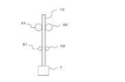
図1に端面図を示した本発明の絶縁電線の一実施態様は、1本の導体1と、導体1の外周を被覆する内側絶縁層2と、内側絶縁層2を被覆する外側絶縁層3からなる絶縁電線10である。
絶縁電線の好ましい形態は、上記図3に示したものに限られず、上述のとおり、複数の導体を有してもよい。また、導体の配置は、撚りあわされていても、並置状態でもよい。
A preferred embodiment of the insulated wire of the present invention will be described with reference to the drawings.
One embodiment of the insulated wire of the present invention whose end surface is shown in FIG. 1 is an embodiment of one
The preferred form of the insulated wire is not limited to that shown in FIG. 3, and may have a plurality of conductors as described above. Further, the arrangement of the conductors may be twisted or juxtaposed.
内側絶縁層(X)と厚肉外側絶縁層(Y)とは、後述する絶縁層の皮むき試験において容易に分離(剥離)しない程度の密着力で接していることが好ましい。 It is preferable that the inner insulating layer (X) and the thick outer insulating layer (Y) are in contact with each other with an adhesive force that does not easily separate (peeling) in the peeling test of the insulating layer described later.
本発明の絶縁電線の各層について、その成分を含めてさらに詳細に説明する。 Each layer of the insulated wire of the present invention will be described in more detail including its components.
〔内側絶縁層(X)〕
内側絶縁層(X)は、上記100%モジュラスを示す材料からなる層であれば、その材料等については特に限定されない。内側絶縁層(X)は、ポリオレフィン樹脂を含んでなる層であることが好ましく、後述するシラン架橋性組成物(Ax)のシラノール縮合硬化物からなる層であることがより好ましい。
内側絶縁層(X)は、電線、電気ケーブル、電気コード等において、一般的に使用されている各種の添加剤を本発明の効果を損なわない範囲で含有してもよい。
[Inner insulation layer (X)]
The inner insulating layer (X) is not particularly limited as long as it is a layer made of the above-mentioned material exhibiting 100% modulus. The inner insulating layer (X) is preferably a layer containing a polyolefin resin, and more preferably a layer made of a silanol condensed cured product of the silane crosslinkable composition (Ax) described later.
The inner insulating layer (X) may contain various additives generally used in electric wires, electric cables, electric cords, etc. as long as the effects of the present invention are not impaired.
− ポリオレフィン樹脂 −
ポリオレフィン樹脂は、エチレン性不飽和結合を有する化合物(通常、アルケン)を重合又は共重合して得られる重合体からなる樹脂であれば、特に限定されない。従来、電線及びケーブルに使用されている公知のポリオレフィン樹脂を使用することができる。
ポリオレフィン樹脂としては、例えば、ポリエチレン、ポリプロピレン、エチレン−α−オレフィン共重合体、酸共重合成分もしくは酸エステル共重合成分を有するポリオレフィン共重合体等の重合体からなる樹脂、これら重合体のゴム又はエラストマー(後述するエチレンゴム及びスチレン系エラストマーを除く)等が挙げられる。
内側絶縁層(X)は、ポリオレフィン樹脂を1種単独で、又は2種以上を含有していてもよい。
− Polyolefin resin −
The polyolefin resin is not particularly limited as long as it is a resin made of a polymer obtained by polymerizing or copolymerizing a compound having an ethylenically unsaturated bond (usually an alkene). Known polyolefin resins conventionally used for electric wires and cables can be used.
Examples of the polyolefin resin include resins made of polymers such as polyethylene, polypropylene, ethylene-α-olefin copolymers, and polyolefin copolymers having an acid copolymer component or an acid ester copolymer component, rubber of these polymers, or rubber. Examples thereof include elastomers (excluding ethylene rubber and styrene-based polymers described later).
The inner insulating layer (X) may contain one type of polyolefin resin alone or two or more types.
ポリエチレン樹脂としては、高密度ポリエチレン(HDPE)、低密度ポリエチレン(LDPE)、超高分子量ポリエチレン(UHMW−PE)、直鎖型低密度ポリエチレン(LLDPE)、超低密度ポリエチレン(VLDPE)が挙げられる。なかでも、直鎖型低密度ポリエチレン、低密度ポリエチレンが好ましい。 Examples of the polyethylene resin include high density polyethylene (HDPE), low density polyethylene (LDPE), ultra high molecular weight polyethylene (UHMW-PE), linear low density polyethylene (LLDPE), and ultra low density polyethylene (VLDPE). Of these, linear low-density polyethylene and low-density polyethylene are preferable.
ポリプロピレン樹脂は、プロピレンの単独重合体のほか、共重合体としてランダムポリプロピレン等のエチレン−プロピレン共重合体及びブロックポリプロピレンの樹脂を包含する。 The polypropylene resin includes, in addition to the homopolymer of propylene, an ethylene-propylene copolymer such as random polypropylene as a copolymer and a resin of block polypropylene.
エチレン−α−オレフィン共重合体からなる樹脂としては、エチレン−ブチレン共重合体、及びシングルサイト触媒存在下に合成されたエチレン−α−オレフィン共重合体等からなる樹脂が挙げられる。 Examples of the resin made of an ethylene-α-olefin copolymer include a resin made of an ethylene-butylene copolymer and an ethylene-α-olefin copolymer synthesized in the presence of a single-site catalyst.
酸共重合成分又は酸エステル共重合成分を有するポリオレフィン共重合体からなる樹脂としては、例えば、エチレン−酢酸ビニル共重合体、エチレン−(メタ)アクリル酸共重合体、エチレン−(メタ)アクリル酸アルキル共重合体(好ましくは炭素数1〜12)共重合体等からなる各樹脂が挙げられる。 Examples of the resin composed of a polyolefin copolymer having an acid copolymer component or an acid ester copolymer component include an ethylene-vinyl acetate copolymer, an ethylene- (meth) acrylic acid copolymer, and an ethylene- (meth) acrylic acid. Examples thereof include resins made of alkyl copolymers (preferably having 1 to 12 carbon atoms) copolymers and the like.
ポリオレフィン樹脂は、通常用いられる不飽和カルボン酸又はその誘導体等で酸変性されていてもよい。 The polyolefin resin may be acid-modified with an unsaturated carboxylic acid or a derivative thereof, which is usually used.
ポリオレフィン樹脂は、ポリエチレン、エチレン−α−オレフィン共重合体、酸共重合成分もしくは酸エステル共重合成分を有するポリオレフィン共重合体、及びポリプロピレンのいずれか、又はこれらの組み合わせを含有することが好ましい。
またポリオレフィン樹脂は架橋されていてもよい。このような架橋ポリオレフィン樹脂としては、シラン架橋ポリエチレン、シラン架橋エチレン−α−オレフィン共重合体を用いることができる。
The polyolefin resin preferably contains polyethylene, an ethylene-α-olefin copolymer, a polyolefin copolymer having an acid copolymer component or an acid ester copolymer component, and polypropylene, or a combination thereof.
Further, the polyolefin resin may be crosslinked. As such a crosslinked polyolefin resin, a silane crosslinked polyethylene or a silane crosslinked ethylene-α-olefin copolymer can be used.
− シラン架橋性組成物(Ax) −
内側絶縁層(X)は、下記〔シラン架橋性組成物(Ax)〕のシラノール縮合硬化物からなることがより好ましい。〔シラン架橋性組成物(Ax)〕
ベース樹脂(Rx)100質量部に対して、無機フィラー(Fx)1〜400質量部と、ベース樹脂(Rx)とグラフト化反応したシランカップリング剤(Sx)1〜15.0質量部と、シラノール縮合触媒(Cx)とを含有するシラン架橋性組成物(Ax)
シラン架橋性組成物(Ax)は、後述する工程(a)及び(b)により調製することができる。
シラン架橋性組成物(Ax)中の各成分の好ましい含有量は、後述する工程(a)〜(d)を有する絶縁電線の製造方法における各成分の配合量と同じであり、好ましい範囲も同様である。
− Silane crosslinkable composition (Ax) −
The inner insulating layer (X) is more preferably made of the silanol condensed cured product of the following [silane crosslinkable composition (Ax)]. [Silane crosslinkable composition (Ax)]
1 to 400 parts by mass of the inorganic filler (Fx) and 1 to 15.0 parts by mass of the silane coupling agent (Sx) grafted with the base resin (Rx) with respect to 100 parts by mass of the base resin (Rx). Silane crosslinkable composition (Ax) containing silanol condensation catalyst (Cx)
The silane crosslinkable composition (Ax) can be prepared by the steps (a) and (b) described later.
The preferable content of each component in the silane crosslinkable composition (Ax) is the same as the blending amount of each component in the method for producing an insulated wire having steps (a) to (d) described later, and the preferred range is also the same. Is.
以下、シラン架橋性組成物(Ax)の成分、及びその調製に用いる材料について説明する。 Hereinafter, the components of the silane crosslinkable composition (Ax) and the materials used for the preparation thereof will be described.
<ベース樹脂(Rx)>
ベース樹脂(Rx)は、後述する有機過酸化物から発生したラジカルの存在下において、シランカップリング剤のグラフト化反応部位とグラフト化反応可能な部位(例えば、炭素鎖の不飽和結合部位、水素原子を有する炭素原子)を主鎖中又はその末端に有している。
ベース樹脂(Rx)としては、ポリオレフィン樹脂、エチレンゴム、及びスチレン系エラストマーのいずれか、又はこれらの組み合わせが挙げられる。ベース樹脂(Rx)としては、より具体的には、ポリエチレン樹脂、ポリプロピレン樹脂、エチレン−α−オレフィン共重合体樹脂、酸共重合成分又は酸エステル共重合成分を有するポリオレフィン共重合体からなる樹脂、エチレン−プロピレンゴム、エチレン−α−オレフィン−ジエンゴム、及びスチレン系エラストマーのいずれか、又はこれらの組み合わせが挙げられる。また、ベース樹脂(Rx)の一部に非芳香族有機油や可塑剤を用いてもよい。
ポリオレフィン樹脂としては、上記で説明したポリオレフィン樹脂を用いることができる。なかでも、ポリエチレン樹脂及びポリプロピレン樹脂が好ましい。
エチレンゴム及びスチレン系エラストマーは、以下のものを使用することができる。
<Base resin (Rx)>
The base resin (Rx) has a grafting reaction site of a silane coupling agent and a site capable of a grafting reaction (for example, an unsaturated bond site of a carbon chain, hydrogen) in the presence of radicals generated from an organic peroxide described later. It has a carbon atom having an atom) in the main chain or at the end thereof.
Examples of the base resin (Rx) include any one of polyolefin resin, ethylene rubber, and styrene-based elastomer, or a combination thereof. More specifically, the base resin (Rx) is a resin composed of a polyethylene resin, a polypropylene resin, an ethylene-α-olefin copolymer resin, an acid copolymer component, or a polyolefin copolymer having an acid ester copolymer component. Examples thereof include any one of ethylene-propylene rubber, ethylene-α-olefin-diene rubber, and styrene-based elastomer, or a combination thereof. Further, a non-aromatic organic oil or a plasticizer may be used as a part of the base resin (Rx).
As the polyolefin resin, the polyolefin resin described above can be used. Of these, polyethylene resin and polypropylene resin are preferable.
The following ethylene rubber and styrene-based elastomer can be used.
− エチレンゴム −
エチレンゴムは、エチレン性不飽和結合を有する化合物を共重合して得られる共重合体からなるゴム(エラストマーを含む)であれば特に限定されず、公知のものを使用することができる。エチレンゴムとしては、好ましくは、エチレンとα−オレフィンとの共重合体、エチレンとα−オレフィンとジエンとの三元共重合体からなるゴムが挙げられる。三元共重合体のジエン構成成分は、共役ジエン構成成分であっても非共役ジエン構成成分であってもよく、非共役ジエン構成成分が好ましい。
− Ethylene rubber −
The ethylene rubber is not particularly limited as long as it is a rubber (including an elastomer) made of a copolymer obtained by copolymerizing a compound having an ethylenically unsaturated bond, and known ones can be used. Preferred examples of ethylene rubber include rubbers composed of a copolymer of ethylene and α-olefin and a ternary copolymer of ethylene, α-olefin and diene. The diene component of the ternary copolymer may be a conjugated diene component or a non-conjugated diene component, and a non-conjugated diene component is preferable.
α−オレフィン構成成分としては、炭素数3〜12の各α−オレフィン構成成分が好ましく、具体例としては、プロピレン、1−ブテン、1−ヘキセン、4−メチル−1−ペンテン、1−オクテン、1−デセン、1−ドデセン等の各構成成分が挙げられる。共役ジエン構成成分の具体例としては、例えば、ブタジエン、イソプレン、1,3−ペンタジエン、2,3−ジメチル−1,3−ブタジエン等の各構成成分が挙げられ、ブタジエン構成成分等が好ましい。非共役ジエン構成成分の具体例としては、例えば、ジシクロペンタジエン(DCPD)、エチリデンノルボルネン(ENB)、1,4−ヘキサジエン等の各構成成分が挙げられ、エチリデンノルボルネン構成成分が好ましい。 As the α-olefin component, each α-olefin component having 3 to 12 carbon atoms is preferable, and specific examples thereof include propylene, 1-butene, 1-hexene, 4-methyl-1-pentene, 1-octene, and the like. Each component such as 1-decene and 1-dodecene can be mentioned. Specific examples of the conjugated diene constituents include, for example, butadiene, isoprene, 1,3-pentadiene, 2,3-dimethyl-1,3-butadiene and the like, and butadiene constituents and the like are preferable. Specific examples of the non-conjugated diene component include, for example, dicyclopentadiene (DCPD), ethylidene norbornene (ENB), 1,4-hexadiene and the like, and the ethylylidene norbornene component is preferable.
エチレンとα−オレフィンとの共重合体からなるゴムとしては、例えば、エチレン−プロピレンゴム、エチレン−ブテンゴム、エチレン−オクテンゴム等が挙げられる。エチレンとα−オレフィンとジエンとの三元共重合体からなるゴムとしては、エチレン−プロピレン−ジエンゴム、エチレン−ブテン−ジエンゴム等が挙げられる。
なかでも、エチレン−プロピレンゴム、エチレン−ブテンゴム、エチレン−プロピレン−ジエンゴム、エチレン−ブテン−ジエンゴムが好ましく、エチレン−プロピレンゴム及びエチレン−プロピレン−ジエンゴムがより好ましい。
Examples of the rubber made of a copolymer of ethylene and α-olefin include ethylene-propylene rubber, ethylene-butene rubber, ethylene-octene rubber and the like. Examples of the rubber composed of a ternary copolymer of ethylene, α-olefin and diene include ethylene-propylene-diene rubber and ethylene-butene-diene rubber.
Of these, ethylene-propylene rubber, ethylene-butene rubber, ethylene-propylene-diene rubber, and ethylene-butene-diene rubber are preferable, and ethylene-propylene rubber and ethylene-propylene-diene rubber are more preferable.
− スチレン系エラストマー −
スチレン系エラストマーは、分子内に芳香族ビニル化合物を構成成分とする重合体からなるものをいう。
スチレン系エラストマーとしては、共役ジエン化合物と芳香族ビニル化合物とのブロック共重合体及びランダム共重合体、又は、それらの水素添加物等からなるものが好ましい。
スチレン系エラストマーとしては、例えば、スチレン−エチレン−ブチレン−スチレンブロック共重合体(SEBS)、スチレン−イソプレン−スチレンブロック共重合体(SIS)、水素化SBS、スチレン−エチレン−エチレン−プロピレン−スチレンブロック共重合体(SEEPS)、スチレン−エチレン−プロピレン−スチレンブロック共重合体(SEPS)、水素化SIS、水素化スチレン・ブタジエンゴム(HSBR)、水素化アクリロニトリル・ブタジエンゴム(HNBR)等からなるものを挙げることができる。
− Styrene-based elastomer −
The styrene-based elastomer refers to a polymer composed of an aromatic vinyl compound in the molecule.
The styrene-based elastomer is preferably a block copolymer and a random copolymer of a conjugated diene compound and an aromatic vinyl compound, or a hydrogenated product thereof.
Examples of the styrene-based elastomer include styrene-ethylene-butylene-styrene block copolymer (SEBS), styrene-isoprene-styrene block copolymer (SIS), hydride SBS, and styrene-ethylene-ethylene-propylene-styrene block. Styrene-ethylene-propylene-styrene block copolymer (SEPS), hydride SIS, hydride styrene-butadiene rubber (HSBR), hydride acrylonitrile-butadiene rubber (HNBR), etc. Can be mentioned.
− 非芳香族有機油 −
非芳香族有機油は、芳香族環を構成する炭素原子数が全炭素数に対して30%未満のものをいい、樹脂組成物に通常用いられるものを特に制限されることなく用いることができる。非芳香族有機油としては、パラフィン鎖を構成する炭素原子数が全炭素数に対して50%以上であるパラフィン系オイル、及びナフテン環を構成する炭素原子数が全炭素数に対して30〜40%であり、パラフィン鎖を構成する炭素原子数が全炭素数に対して50%未満であるナフテン系オイルが挙げられ、パラフィン系オイルが好ましい。非芳香族有機油は、1種類を単独で用いてもよいし、2種類以上を併用してもよい。
− Non-aromatic organic oil −
The non-aromatic organic oil means that the number of carbon atoms constituting the aromatic ring is less than 30% with respect to the total number of carbon atoms, and those usually used for a resin composition can be used without particular limitation. .. Non-aromatic organic oils include paraffin-based oils in which the number of carbon atoms constituting the paraffin chain is 50% or more of the total number of carbon atoms, and the number of carbon atoms constituting the naphthen ring is 30 to 30 to the total number of carbon atoms. Examples thereof include naphthenic oils having 40% and less than 50% of the total number of carbon atoms constituting the paraffin chain, and paraffinic oils are preferable. One type of non-aromatic organic oil may be used alone, or two or more types may be used in combination.
− 他の樹脂成分 −
ベース樹脂(Rx)は上記以外の樹脂成分(他の樹脂成分)を含んでいてもよい。他の樹脂成分は、特に制限されず、グラフト化反応可能な部位を有していてもいなくてもよい。
− Other resin components −
The base resin (Rx) may contain a resin component (other resin component) other than the above. The other resin components are not particularly limited and may or may not have a site capable of a grafting reaction.
ベース樹脂(Rx)は、上述の成分の他に、後述する添加剤を含有していてもよい。 The base resin (Rx) may contain an additive described later in addition to the above-mentioned components.
このベース樹脂(Rx)は、各成分の合計が100質量%となるように、各成分の含有率が下記範囲内から選択される。
ベース樹脂(Rx)中の、ポリオレフィン樹脂、エチレンゴム、及びスチレン系エラストマーの合計含有率は、特に制限されず、50質量%以上が好ましく、60質量%以上がより好ましく、70質量%以上がさらに好ましい。上限は、100質量%である。
ベース樹脂(Rx)中の、エチレンゴム、及びスチレン系エラストマーの合計含有率は、特に制限されず、0〜60質量%が好ましく、5〜50質量%以上がより好ましく、10〜45質量%以上がさらに好ましい。
ベース樹脂(Rx)中の、ポリオレフィン樹脂の含有率は、特に限定されず、上記合計含有率を満たす範囲内で適宜に設定されることが好ましい。ベース樹脂(Rx)中の、ポリオレフィン樹脂の含有率は、100〜10質量%が好ましく、95〜10質量%がより好ましく、80〜25質量%がさらに好ましく、70〜35質量%が特に好ましい。
ベース樹脂(Rx)中の、エチレンゴムの含有率は、特に限定されず、上記合計含有率を満たす範囲内で適宜に設定されることが好ましい。ベース樹脂(Rx)中の、エチレンゴムの含有率は、0〜85質量%が好ましく、0〜50質量%がより好ましく、0〜35質量%がさらに好ましい。
ベース樹脂(Rx)中の、スチレン系エラストマーの含有率は、上記合計含有率を満たす範囲内で適宜に設定されることが好ましい。ベース樹脂(Rx)中の、スチレン系エラストマーの含有率は、0〜55質量%が好ましく、5〜40質量%がより好ましく、10〜35質量%がさらに好ましい。
ベース樹脂(Rx)中の、非芳香族有機油の含有率は、特に制限されないが、0質量%以上エチレンゴム及びスチレン系エラストマーの合計量と同量以下、好ましくは3質量%以上エチレンゴム及びスチレン系エラストマーの合計量の80%以下が好ましい。
ベース樹脂(Rx)は、エチレンゴム、スチレン系エラストマー及び非芳香族有機油の少なくとも一種とポリオレフィン樹脂とを含有することが好ましい。
内側絶縁層(X)の100%モジュラス(Mx)を外側絶縁層(Y)の100%モジュラス(My)より高くする観点からは、ベース樹脂(Rx)中の、エチレンゴム、スチレン系エラストマー及び非芳香族有機油の合計含有量(Tx)は、後述するベース樹脂(Ry)中の、エチレンゴム、スチレン系エラストマー及び非芳香族有機油の合計含有量(Ty)よりも少ないことが好ましい。具体的には、合計含有量(Tx)は合計含有量(Ty)に対して、10〜80質量%少ないことが好ましく、30〜60質量%少ないことがより好ましい。合計含有量(Tx)は、0〜55質量%が好ましく、5〜50質量%以上がより好ましく、10〜45質量%以上がさらに好ましい。
In this base resin (Rx), the content of each component is selected from the following range so that the total of each component is 100% by mass.
The total content of the polyolefin resin, ethylene rubber, and styrene-based elastomer in the base resin (Rx) is not particularly limited, and is preferably 50% by mass or more, more preferably 60% by mass or more, and further 70% by mass or more. preferable. The upper limit is 100% by mass.
The total content of ethylene rubber and styrene-based elastomer in the base resin (Rx) is not particularly limited, and is preferably 0 to 60% by mass, more preferably 5 to 50% by mass or more, and 10 to 45% by mass or more. Is even more preferable.
The content of the polyolefin resin in the base resin (Rx) is not particularly limited, and is preferably set appropriately within a range satisfying the above total content. The content of the polyolefin resin in the base resin (Rx) is preferably 100 to 10% by mass, more preferably 95 to 10% by mass, further preferably 80 to 25% by mass, and particularly preferably 70 to 35% by mass.
The content of ethylene rubber in the base resin (Rx) is not particularly limited, and is preferably set appropriately within a range satisfying the above total content. The content of ethylene rubber in the base resin (Rx) is preferably 0 to 85% by mass, more preferably 0 to 50% by mass, and even more preferably 0 to 35% by mass.
The content of the styrene-based elastomer in the base resin (Rx) is preferably set appropriately within a range that satisfies the above total content. The content of the styrene-based elastomer in the base resin (Rx) is preferably 0 to 55% by mass, more preferably 5 to 40% by mass, and even more preferably 10 to 35% by mass.
The content of the non-aromatic organic oil in the base resin (Rx) is not particularly limited, but is 0% by mass or more and equal to or less than the total amount of ethylene rubber and styrene-based elastomer, preferably 3% by mass or more of ethylene rubber and It is preferably 80% or less of the total amount of the styrene-based elastomer.
The base resin (Rx) preferably contains at least one of ethylene rubber, a styrene-based elastomer and a non-aromatic organic oil, and a polyolefin resin.
From the viewpoint of making the 100% modulus (Mx) of the inner insulating layer (X) higher than the 100% modulus (My) of the outer insulating layer (Y), ethylene rubber, styrene-based elastomer and non-ethylene rubber in the base resin (Rx) The total content (Tx) of the aromatic organic oil is preferably smaller than the total content (Ty) of the ethylene rubber, the styrene elastomer and the non-aromatic organic oil in the base resin (Ry) described later. Specifically, the total content (Tx) is preferably 10 to 80% by mass less than the total content (Ty), and more preferably 30 to 60% by mass less. The total content (Tx) is preferably 0 to 55% by mass, more preferably 5 to 50% by mass or more, and further preferably 10 to 45% by mass or more.
<有機過酸化物(Px)>
有機過酸化物(Px)は、少なくとも熱分解によりラジカルを発生して、触媒として、シランカップリング剤(Sx)のベース樹脂(Rx)へのラジカル反応によるグラフト化反応(シランカップリング剤(Sx)のグラフト化反応部位とベース樹脂(Rx)のグラフト化反応可能な部位との共有結合形成反応であって、(ラジカル)付加反応ともいう。)を生起させる働きをする。
有機過酸化物(Px)としては、上記機能を有し、ラジカル重合又は従来のシラン架橋法に用いられるものを特に制限されずに用いることができる。例えば、ベンゾイルパーオキサイド、ジクミルパーオキサイド(DCP)、2,5−ジメチル−2,5−ジ−(tert−ブチルパーオキシ)ヘキサン又は2,5−ジメチル−2,5−ジ−(tert−ブチルペルオキシ)ヘキシン−3が好ましい。
有機過酸化物(Px)の分解温度は、80〜195℃が好ましく、125〜180℃が特に好ましい。本発明において、有機過酸化物(Px)の分解温度とは、単一組成の有機過酸化物(Px)を加熱したとき、ある一定の温度又は温度域でそれ自身が2種類以上の化合物に分解反応を起こす温度を意味する。具体的には、DSC法等の熱分析により、窒素ガス雰囲気下で5℃/分の昇温速度で、室温から加熱したとき、吸熱又は発熱を開始する温度をいう。
有機過酸化物(Px)は、1種類を用いても、2種類以上を用いてもよい。
<Organic peroxide (Px)>
The organic peroxide (Px) generates radicals by at least thermal decomposition, and as a catalyst, a grafting reaction (silane coupling agent (Sx)) by a radical reaction of a silane coupling agent (Sx) with a base resin (Rx). ) And the site capable of the grafting reaction of the base resin (Rx), which is a covalent bond forming reaction (also referred to as a (radical) addition reaction).
As the organic peroxide (Px), those having the above-mentioned functions and used in radical polymerization or the conventional silane cross-linking method can be used without particular limitation. For example, benzoyl peroxide, dicumyl peroxide (DCP), 2,5-dimethyl-2,5-di- (tert-butylperoxy) hexane or 2,5-dimethyl-2,5-di- (tert-). Butylperoxy) hexin-3 is preferred.
The decomposition temperature of the organic peroxide (Px) is preferably 80 to 195 ° C, particularly preferably 125 to 180 ° C. In the present invention, the decomposition temperature of an organic peroxide (Px) means that when a single composition of an organic peroxide (Px) is heated, it itself becomes two or more kinds of compounds at a certain temperature or temperature range. It means the temperature at which a decomposition reaction occurs. Specifically, it refers to the temperature at which heat absorption or heat generation starts when heated from room temperature at a heating rate of 5 ° C./min in a nitrogen gas atmosphere by thermal analysis such as the DSC method.
As the organic peroxide (Px), one type may be used, or two or more types may be used.
<無機フィラー(Fx)>
本発明において、無機フィラー(Fx)は、その表面に、シランカップリング剤(Sx)のシラノール基等の反応部位と水素結合等が形成できる部位もしくは共有結合による化学結合しうる部位を有するものであれば特に制限なく用いることができる。この無機フィラー(Fx)における、シランカップリング剤(Sx)の反応部位と化学結合しうる部位としては、OH基(水酸基、含水もしくは結晶水の水分子、カルボキシ基等のOH基)、アミノ基、SH基等が挙げられる。
無機フィラー(Fx)としては、例えば、水酸化アルミニウム、水酸化マグネシウム、炭酸カルシウム、炭酸マグネシウム、ケイ酸カルシウム、ケイ酸マグネシウム、酸化カルシウム、酸化マグネシウム、酸化アルミニウム、窒化アルミニウム、ほう酸アルミニウムウイスカ、水和ケイ酸アルミニウム、水和ケイ酸マグネシウム、塩基性炭酸マグネシウム、ハイドロタルサイト等の水酸基あるいは結晶水を有する化合物のような金属水和物や、窒化ほう素、シリカ(結晶質シリカ、非晶質シリカ等)、カーボン、クレー、酸化亜鉛、酸化錫、酸化チタン、酸化モリブデン、三酸化アンチモン、シリコーン化合物、石英、タルク、ほう酸亜鉛、ホワイトカーボン、硼酸亜鉛、ヒドロキシスズ酸亜鉛、スズ酸亜鉛を使用することができる。
無機フィラー(Fx)は、これらのなかでも、シリカ、水酸化アルミニウム、及び水酸化マグネシウムの少なくとも1種が好ましい。
無機フィラー(Fx)は、1種類を単独で配合してもよいし、2種類以上を併用してもよい。
<Inorganic filler (Fx)>
In the present invention, the inorganic filler (Fx) has a reaction site such as a silanol group of a silane coupling agent (Sx) and a site capable of forming a hydrogen bond or a site capable of chemically bonding by a covalent bond on the surface thereof. If there is, it can be used without particular limitation. In this inorganic filler (Fx), OH groups (hydroxyl groups, water molecules of water-containing or water of crystallization, OH groups such as carboxy groups) and amino groups can be chemically bonded to the reaction site of the silane coupling agent (Sx). , SH group and the like.
Examples of the inorganic filler (Fx) include aluminum hydroxide, magnesium hydroxide, calcium carbonate, magnesium carbonate, calcium silicate, magnesium silicate, calcium oxide, magnesium oxide, aluminum oxide, aluminum nitride, aluminum borate whisk, and hydration. Metal hydrates such as aluminum silicate, hydrated magnesium silicate, basic magnesium carbonate, hydrotalcite and other compounds having hydroxyl groups or crystalline water, boron nitride, silica (crystalline silica, amorphous silica) Etc.), carbon, clay, zinc oxide, tin oxide, titanium oxide, molybdenum oxide, antimony trioxide, silicone compound, quartz, talc, zinc borate, white carbon, zinc borate, zinc hydroxytinate, zinc tint be able to.
Among these, the inorganic filler (Fx) is preferably at least one of silica, aluminum hydroxide, and magnesium hydroxide.
One type of inorganic filler (Fx) may be blended alone, or two or more types may be used in combination.
無機フィラー(Fx)の平均粒径は、0.2〜10μmが好ましく、0.3〜8μmがより好ましく、0.4〜5μmがさらに好ましく、0.4〜3μmが特に好ましい。平均粒径は、アルコールや水で分散させて、レーザ回折/散乱式粒子径分布測定装置等の光学式粒径測定器によって求められる。 The average particle size of the inorganic filler (Fx) is preferably 0.2 to 10 μm, more preferably 0.3 to 8 μm, further preferably 0.4 to 5 μm, and particularly preferably 0.4 to 3 μm. The average particle size is determined by an optical particle size measuring device such as a laser diffraction / scattering type particle size distribution measuring device, which is dispersed with alcohol or water.
無機フィラー(Fx)は、シランカップリング剤等で表面処理した無機フィラーを使用することができる。例えば、シランカップリング剤表面処理金属水和物として、キスマ5L、キスマ5P(いずれも商品名、水酸化マグネシウム、協和化学社製等)や水酸化アルミニウムなどが挙げられる。シランカップリング剤による無機フィラーの表面処理量は、特に限定されないが、例えば、2質量%以下である。 As the inorganic filler (Fx), an inorganic filler surface-treated with a silane coupling agent or the like can be used. For example, examples of the silane coupling agent surface-treated metal hydrate include Kisuma 5L, Kisma 5P (trade names, magnesium hydroxide, manufactured by Kyowa Chemical Industry Co., Ltd., etc.), aluminum hydroxide, and the like. The amount of the surface treatment of the inorganic filler with the silane coupling agent is not particularly limited, but is, for example, 2% by mass or less.
<シランカップリング剤(Sx)>
シランカップリング剤(Sx)は、シラン架橋性組成物(Ax)においては、ベース樹脂(Rx)とグラフト化反応している。ベース樹脂(Rx)とグラフト化反応したシランカップリング剤(Sx)(シラングラフト樹脂)は、市販品を用いることもできるが、後述する方法で調製したものが物性(耐熱性と強度との両立等)の点で、好ましい。
上記シラングラフト樹脂の調製に用いる、シランカップリング剤(Sx)としては、有機過酸化物(Px)の分解により生じたラジカルの存在下で、ベース樹脂(Rx)のグラフト化反応可能な部位にグラフト化反応しうる部位(基又は原子)と、シラノール縮合可能な加水分解性シリル基とを有するものであれば、特に限定されない。このようなシランカップリング剤(Sy)としては、従来のシラン架橋法に使用されているシランカップリング剤が挙げられる。
シランカップリング剤(Sx)としては、不飽和基を有するシランカップリング剤が挙げられ、具体的には、ビニルトリメトキシシラン、ビニルトリエトキシシラン、ビニルトリブトキシシラン、ビニルジメトキシエトキシシラン、ビニルジメトキシブトキシシラン、ビニルジエトキシブトキシシラン、アリルトリメトキシシラン、アリルトリエトキシシラン、ビニルトリアセトキシシラン等のビニルシラン、(メタ)アクリロキシシラン等が挙げられる。中でも、ビニルトリメトキシシラン又はビニルトリエトキシシランが特に好ましい。
シランカップリング剤(Sx)は、1種類を用いても、2種類以上を用いてもよい。
シランカップリング剤(Sx)は、そのままの形態で用いてもよいし、溶剤で希釈した形態で用いてもよい。
<Silane coupling agent (Sx)>
The silane coupling agent (Sx) has a grafting reaction with the base resin (Rx) in the silane crosslinkable composition (Ax). As the silane coupling agent (Sx) (silane graft resin) grafted with the base resin (Rx), a commercially available product can be used, but the one prepared by the method described later has physical properties (both heat resistance and strength). Etc.), which is preferable.
The silane coupling agent (Sx) used in the preparation of the silane graft resin is a site capable of a grafting reaction of the base resin (Rx) in the presence of radicals generated by decomposition of the organic peroxide (Px). It is not particularly limited as long as it has a site (group or atom) capable of a grafting reaction and a hydrolyzable silyl group capable of silanol condensation. Examples of such a silane coupling agent (Sy) include silane coupling agents used in the conventional silane cross-linking method.
Examples of the silane coupling agent (Sx) include silane coupling agents having an unsaturated group, and specific examples thereof include vinyltrimethoxysilane, vinyltriethoxysilane, vinyltributoxysilane, vinyldimethoxyethoxysilane, and vinyldimethoxy. Examples thereof include vinylsilanes such as butoxysilane, vinyldiethoxybutoxysilane, allyltrimethoxysilane, allyltriethoxysilane, and vinyltriacetoxysilane, and (meth) acryloxisilane. Of these, vinyltrimethoxysilane or vinyltriethoxysilane is particularly preferable.
As the silane coupling agent (Sx), one type may be used, or two or more types may be used.
The silane coupling agent (Sx) may be used as it is or in a solvent-diluted form.
<シラノール縮合触媒(Cx)>
シラノール縮合触媒(Cx)は、ベース樹脂(Rx)にグラフトされたシランカップリング剤(Sx)の加水分解性シリル基を水分の存在下で縮合反応(促進)させる働きがある。このシラノール縮合触媒(Cx)の働きに基づき、シランカップリング剤(Sx)を介して、ベース樹脂(Rx)同士が架橋される。
このようなシラノール縮合触媒(Cx)としては、特に制限されず、例えば、有機スズ化合物、金属石けん、白金化合物等が挙げられる。有機スズ化合物としては、例えば、ジブチルスズジラウレート、ジオクチルスズジラウレート、ジブチルスズジオクチエート、ジブチルスズジアセテート等の有機スズ化合物が挙げられる。
シラノール縮合触媒(Cx)は、1種類を用いても、2種類以上を用いてもよい。
<Silanol condensation catalyst (Cx)>
The silanol condensation catalyst (Cx) has a function of causing a condensation reaction (promotion) of the hydrolyzable silyl group of the silane coupling agent (Sx) grafted on the base resin (Rx) in the presence of water. Based on the action of the silanol condensation catalyst (Cx), the base resins (Rx) are crosslinked with each other via the silane coupling agent (Sx).
The silanol condensation catalyst (Cx) is not particularly limited, and examples thereof include an organotin compound, a metallic soap, and a platinum compound. Examples of the organotin compound include organotin compounds such as dibutyltin dilaurate, dioctyltin dilaurate, dibutyltin dioctate, and dibutyltin diacetate.
As the silanol condensation catalyst (Cx), one type may be used, or two or more types may be used.
<キャリア樹脂(CRx)>
本発明に用いられるシラノール縮合触媒(Cx)は、所望により樹脂に混合される。このような樹脂(キャリア樹脂(CRx)ともいう)としては、特に限定されないが、ベース樹脂(Rx)以外の樹脂又はベース樹脂(Rx)の一部を用いることができる。
キャリア樹脂(CRx)としては、ポリオレフィン樹脂が好ましく、シラノール縮合触媒(Cx)と親和性がよく耐熱性を付与できる点で、ポリエチレンが特に好ましい。
<Carrier resin (CRx)>
The silanol condensation catalyst (Cx) used in the present invention is optionally mixed with the resin. Such a resin (also referred to as a carrier resin (CRx)) is not particularly limited, but a resin other than the base resin (Rx) or a part of the base resin (Rx) can be used.
As the carrier resin (CRx), a polyolefin resin is preferable, and polyethylene is particularly preferable because it has a good affinity with the silanol condensation catalyst (Cx) and can impart heat resistance.
<添加剤>
内側絶縁層(X)は、電線、電気ケーブル、電気コード等において、一般的に使用されている各種の添加剤を本発明の効果を損なわない範囲で含有してもよい。このような添加剤として、例えば、架橋助剤、酸化防止剤、滑剤、金属不活性剤、又は、充填剤(難燃(助)剤を含む。)等が挙げられる。
<Additives>
The inner insulating layer (X) may contain various additives generally used in electric wires, electric cables, electric cords, etc. as long as the effects of the present invention are not impaired. Examples of such additives include cross-linking aids, antioxidants, lubricants, metal deactivators, fillers (including flame-retardant (auxiliary) agents) and the like.
酸化防止剤としては、特に限定されないが、例えば、アミン酸化防止剤、フェノール酸化防止剤又は硫黄酸化防止剤等が挙げられ、フェノール酸化防止剤が好ましい。酸化防止剤は、ベース樹脂(Rx)100質量部に対して、好ましくは0.1〜15.0質量部、さらに好ましくは0.1〜10質量部で加えることができる。 The antioxidant is not particularly limited, and examples thereof include an amine antioxidant, a phenol antioxidant, a sulfur antioxidant, and the like, and a phenol antioxidant is preferable. The antioxidant can be added in an amount of preferably 0.1 to 15.0 parts by mass, more preferably 0.1 to 10 parts by mass with respect to 100 parts by mass of the base resin (Rx).
〔厚肉外側絶縁層(Y)〕
厚肉外側絶縁層(Y)は、絶縁電線が内側絶縁層(X)の外側に有する絶縁層の内、最も厚肉の層であり、上記100%モジュラスを示す材料からなる層である。厚肉外側絶縁層(Y)は、下記シラン架橋性組成物(Ay)のシラノール縮合硬化物からなる。厚肉外側絶縁層(Y)を、下記シラン架橋性組成物(Ay)のシラノール縮合硬化物層とすることにより、特にキャブタイヤケーブルの屈曲耐久性、更には絶縁層の皮むき性を高めることができる。
〔シラン架橋性組成物(Ay)〕
エチレンゴム及びスチレン系エラストマーの少なくとも一方を含有するベース樹脂(Ry)100質量部に対して、無機フィラー(Fy)1〜400質量部と、前記ベース樹脂(Ry)とグラフト化反応したシランカップリング剤(Sy)1〜15.0質量部と、シラノール縮合触媒(Cy)とを含有するシラン架橋性組成物(Ay)
シラン架橋性組成物(Ay)は、後述する工程(e)及び(f)により調製することができる。
シラン架橋性組成物(Ay)中の各成分の好ましい含有量は、後述する工程(e)〜(h)を有する絶縁電線の製造方法における各成分の配合量と同じであり、好ましい範囲も同様である。
[Thick outer insulating layer (Y)]
The thick outer insulating layer (Y) is the thickest layer among the insulating layers that the insulated wire has on the outside of the inner insulating layer (X), and is a layer made of the material exhibiting 100% modulus. The thick outer insulating layer (Y) is made of the silanol condensed cured product of the following silane crosslinkable composition (Ay). By using the thick outer insulating layer (Y) as the silanol condensed cured product layer of the following silane crosslinkable composition (Ay), the bending durability of the cabtire cable and the peeling property of the insulating layer are particularly enhanced. Can be done.
[Silane crosslinkable composition (Ay)]
Silane coupling of 1 to 400 parts by mass of an inorganic filler (Fy) and a graft reaction with the base resin (Ry) with respect to 100 parts by mass of a base resin (Ry) containing at least one of an ethylene rubber and a styrene-based elastomer. A silane crosslinkable composition (Ay) containing 1 to 15.0 parts by mass of an agent (Sy) and a silanol condensation catalyst (Cy).
The silane crosslinkable composition (Ay) can be prepared by the steps (e) and (f) described later.
The preferable content of each component in the silane crosslinkable composition (Ay) is the same as the blending amount of each component in the method for producing an insulated wire having steps (e) to (h) described later, and the preferred range is also the same. Is.
以下、シラン架橋性組成物(Ay)の成分、及びその調製に用いる材料について説明する。 Hereinafter, the components of the silane crosslinkable composition (Ay) and the materials used for the preparation thereof will be described.
<ベース樹脂(Ry)>
ベース樹脂(Ry)は、エチレンゴム及びスチレン系エラストマーの少なくとも一方を含有する。エチレンゴム及びスチレン系エラストマーは、後述する有機過酸化物から発生したラジカルの存在下において、シランカップリング剤のグラフト化反応部位とグラフト化反応可能な部位(例えば、炭素鎖の不飽和結合部位、水素原子を有する炭素原子)を主鎖中又はその末端に有している。ベース樹脂(Ry)がエチレンゴム及びスチレン系エラストマーの少なくとも一方を含有することにより、屈曲耐久性に寄与する外側絶縁層を形成することができる。
エチレンゴム及びスチレン系エラストマーとしては、上記[内側絶縁層(X)]で説明したエチレンゴム及びスチレン系エラストマーを用いることができる。
ベース樹脂(Ry)は、上記ゴム又はエラストマー以外の成分を含有していてもよく、含有していてもよい成分としては、例えば、非芳香族有機油が挙げられる。非芳香族有機油としては、上記[内側絶縁層(X)]で説明した非芳香族有機油を用いることができる。
このベース樹脂(Ry)は、各成分の合計が100質量%となるように、各成分の含有率が下記範囲内から選択される。
<Base resin (Ry)>
The base resin (Ry) contains at least one of ethylene rubber and a styrene-based elastomer. In the presence of radicals generated from organic peroxides, which will be described later, ethylene rubber and styrene-based elastomers have a grafting reaction site of a silane coupling agent and a site capable of a grafting reaction (for example, an unsaturated bond site of a carbon chain, etc. It has a carbon atom having a hydrogen atom) in the main chain or at the end thereof. When the base resin (Ry) contains at least one of ethylene rubber and a styrene-based elastomer, an outer insulating layer that contributes to bending durability can be formed.
As the ethylene rubber and the styrene-based elastomer, the ethylene rubber and the styrene-based elastomer described in the above [Inner Insulating Layer (X)] can be used.
The base resin (Ry) may contain components other than the rubber or elastomer, and examples of the components that may be contained include non-aromatic organic oils. As the non-aromatic organic oil, the non-aromatic organic oil described in the above [inner insulating layer (X)] can be used.
In this base resin (Ry), the content of each component is selected from the following range so that the total of each component is 100% by mass.
− 他の樹脂成分 −
ベース樹脂(Ry)は上記以外の樹脂成分(他の樹脂成分)を含んでいてもよい。他の樹脂成分は、特に制限されず、グラフト化反応可能な部位を有していてもいなくてもよい。このような樹脂成分として、ポリオレフィン樹脂が好ましい。ポリオレフィン樹脂としては、上記[内側絶縁層(X)]で説明したポリオレフィン樹脂を用いることができる。
− Other resin components −
The base resin (Ry) may contain a resin component (other resin component) other than the above. The other resin components are not particularly limited and may or may not have a site capable of a grafting reaction. As such a resin component, a polyolefin resin is preferable. As the polyolefin resin, the polyolefin resin described in the above [Inner Insulating Layer (X)] can be used.
ベース樹脂(Ry)は、上述の成分の他に、後述する添加剤を含有していてもよい。 The base resin (Ry) may contain an additive described later in addition to the above-mentioned components.
ベース樹脂(Ry)中の、エチレンゴム及びスチレン系エラストマーの合計含有率は、0質量%を越える限り特に制限されず、5質量%以上が好ましく、10質量%以上がより好ましく、20質量%以上がさらに好ましい。上限値は、特に限定されないが、30質量%以下が好ましく、25質量%以下がより好ましい。
ベース樹脂(Ry)中の、エチレンゴムの含有率は、上記合計含有率を満たす範囲内で適宜に設定される。ベース樹脂(Ry)中の、エチレンゴムの含有率は、0〜85質量%が好ましく、0〜50質量%がより好ましく、0〜35質量%がさらに好ましい。
ベース樹脂(Ry)中の、スチレン系エラストマーの含有率は、上記合計含有率を満たす範囲内で適宜に設定される。ベース樹脂(Ry)中の、スチレン系エラストマーの含有率は、0〜55質量%が好ましく、5〜40質量%がより好ましく、10〜35質量%がさらに好ましい。
ベース樹脂(Ry)中の、非芳香族有機油の含有率は、特に制限されないが、0質量%〜エチレンゴム及びスチレン系エラストマーの合計量と同量以下、好ましくは3質量%からエチレンゴム及びスチレン系エラストマーの合計量の80%以下が好ましい。
ベース樹脂(Ry)中の、ポリオレフィン樹脂の含有率は、特に限定されないが、95〜10質量%が好ましく、80〜25質量%がより好ましく、70〜35質量%がさらに好ましい。
ベース樹脂(Ry)は、エチレンゴム及びスチレン系エラストマーの少なくとも一方に加えて非芳香族有機油を含有することが好ましい。
肉厚外側絶縁層(Y)の100%モジュラス(My)を内側絶縁層(X)の100%モジュラス(Mx)より低くする観点からは、ベース樹脂(Ry)中の、エチレンゴム、スチレン系エラストマー及び非芳香族有機油の合計含有量(Ty)は、上記合計量(Tx)よりも多いことが好ましい。合計含有量(Ty)は、40〜90質量%が好ましく、50〜85質量%以上がより好ましく、55〜80質量%以上がさらに好ましい。
ベース樹脂(Rx)及びベース樹脂(Ry)中のエチレンゴム及び/又はスチレン系エラストマーの含有量を増やすことで、内側絶縁層(X)及び肉厚外側絶縁層(Y)のモジュラスは低下する傾向にあり、柔軟性は高まる傾向にある。さらに、非芳香族有機油及び/又は可塑剤を加えることで、さらにモジュラスは低下する傾向にある。
ベース樹脂(Ry)は、ベース樹脂(Rx)と同種類又は同樹脂系統の樹脂成分を含むことが好ましい。このようにすると、内側絶縁層(X)と外側絶縁層(Y)との接着がより容易となる傾向であり、端末加工時にも内側絶縁層(X)と外側絶縁層(Y)とを一体にむきとりやすく(段剥きにされることなく)、きれいに加工することができる。
The total content of ethylene rubber and styrene-based elastomer in the base resin (Ry) is not particularly limited as long as it exceeds 0% by mass, preferably 5% by mass or more, more preferably 10% by mass or more, and 20% by mass or more. Is even more preferable. The upper limit value is not particularly limited, but is preferably 30% by mass or less, and more preferably 25% by mass or less.
The content of ethylene rubber in the base resin (Ry) is appropriately set within a range satisfying the above total content. The content of ethylene rubber in the base resin (Ry) is preferably 0 to 85% by mass, more preferably 0 to 50% by mass, and even more preferably 0 to 35% by mass.
The content of the styrene-based elastomer in the base resin (Ry) is appropriately set within a range that satisfies the above total content. The content of the styrene-based elastomer in the base resin (Ry) is preferably 0 to 55% by mass, more preferably 5 to 40% by mass, and even more preferably 10 to 35% by mass.
The content of the non-aromatic organic oil in the base resin (Ry) is not particularly limited, but is 0% by mass to equal to or less than the total amount of ethylene rubber and styrene-based elastomer, preferably 3% by mass to ethylene rubber and It is preferably 80% or less of the total amount of the styrene-based elastomer.
The content of the polyolefin resin in the base resin (Ry) is not particularly limited, but is preferably 95 to 10% by mass, more preferably 80 to 25% by mass, and even more preferably 70 to 35% by mass.
The base resin (Ry) preferably contains a non-aromatic organic oil in addition to at least one of ethylene rubber and a styrene-based elastomer.
From the viewpoint of making the 100% modulus (My) of the thick outer insulating layer (Y) lower than the 100% modulus (Mx) of the inner insulating layer (X), ethylene rubber and styrene elastomer in the base resin (Ry). The total content (Ty) of the non-aromatic organic oil and the non-aromatic organic oil is preferably larger than the total content (Tx). The total content (Ty) is preferably 40 to 90% by mass, more preferably 50 to 85% by mass or more, and further preferably 55 to 80% by mass or more.
By increasing the content of ethylene rubber and / or styrene-based elastomer in the base resin (Rx) and the base resin (Ry), the modulus of the inner insulating layer (X) and the thick outer insulating layer (Y) tends to decrease. There is a tendency for flexibility to increase. In addition, the addition of non-aromatic organic oils and / or plasticizers tends to further reduce the modulus.
The base resin (Ry) preferably contains a resin component of the same type or the same resin system as the base resin (Rx). In this way, the inner insulating layer (X) and the outer insulating layer (Y) tend to be more easily adhered to each other, and the inner insulating layer (X) and the outer insulating layer (Y) are integrated even during terminal processing. It is easy to peel off (without being stripped) and can be processed neatly.
<有機過酸化物(Py)>
有機過酸化物(Py)としては、上述の〔内側絶縁層(X)〕で説明した有機過酸化物(Px)を使用することができる。好ましい範囲等についても同様である。
<Organic peroxide (Py)>
As the organic peroxide (Py), the organic peroxide (Px) described in the above-mentioned [Inner Insulating Layer (X)] can be used. The same applies to the preferred range and the like.
<無機フィラー(Fy)>
無機フィラー(Fy)としては、上述の〔内側絶縁層(X)〕で説明した無機フィラー(Fx)を使用することができる。好ましい範囲等についても同様である。
無機フィラー(Fy)としては、水酸化マグネシウムが好ましい。
<Inorganic filler (Fy)>
As the inorganic filler (Fy), the inorganic filler (Fx) described in the above-mentioned [Inner Insulating Layer (X)] can be used. The same applies to the preferred range and the like.
Magnesium hydroxide is preferable as the inorganic filler (Fy).
<シランカップリング剤(Sy)>
シランカップリング剤(Sy)は、シラン架橋性組成物(Ay)においては、ベース樹脂(Ry)とグラフト化反応している。シランカップリング剤(Sx)と同様に、ベース樹脂(Ry)とグラフト化反応したシランカップリング剤(Sy)として、市販品を用いてもよい。
シランカップリング剤(Sy)としては、上述の〔内側絶縁層(X)〕で説明したシランカップリング剤(Sx)を使用することができる。好ましい範囲等についても同様である。
<Silane coupling agent (Sy)>
The silane coupling agent (Sy) has a grafting reaction with the base resin (Ry) in the silane crosslinkable composition (Ay). Similar to the silane coupling agent (Sx), a commercially available product may be used as the silane coupling agent (Sy) grafted with the base resin (Ry).
As the silane coupling agent (Sy), the silane coupling agent (Sx) described in the above-mentioned [Inner Insulating Layer (X)] can be used. The same applies to the preferred range and the like.
<シラノール縮合触媒(Cy)>
シラノール縮合触媒(Cy)としては、上述の〔内側絶縁層(X)〕で説明したシラノール縮合触媒(Cx)を使用することができる。好ましい範囲等についても同様である。
<Silanol condensation catalyst (Cy)>
As the silanol condensation catalyst (Cy), the silanol condensation catalyst (Cx) described in the above-mentioned [Inner Insulation Layer (X)] can be used. The same applies to the preferred range and the like.
<キャリア樹脂(CRy)>
キャリア樹脂(CRy)は、上述の〔内側絶縁層(X)〕で説明したキャリア樹脂(CRx)に対応する。
キャリア樹脂(CRy)としては、ベース樹脂(Ry)の一部を用いることができる。キャリア樹脂(CRy)は、ポリオレフィン樹脂が好ましく、シラノール縮合触媒(Cy)と親和性がよく耐熱性を付与できる点で、ポリエチレン樹脂が特に好ましい。
<Carrier resin (CRy)>
The carrier resin (CRy) corresponds to the carrier resin (CRx) described in the above-mentioned [Inner Insulating Layer (X)].
As the carrier resin (CRy), a part of the base resin (Ry) can be used. The carrier resin (CRy) is preferably a polyolefin resin, and a polyethylene resin is particularly preferable because it has good affinity with the silanol condensation catalyst (Cy) and can impart heat resistance.
<添加剤>
外側絶縁層は、上述の〔内側絶縁層(X)〕で説明した添加剤を、本発明の効果を損なわない範囲で含有していてもよい。添加剤の好ましい範囲等については、上述のものと同様である。
<Additives>
The outer insulating layer may contain the additive described in the above [inner insulating layer (X)] as long as the effect of the present invention is not impaired. The preferred range of additives and the like are the same as those described above.
〔厚肉外側絶縁層(Y)以外の外側絶縁層〕
厚肉外側絶縁層(Y)以外の外側絶縁層は、内側絶縁層(X)よりも100%モジュラスが低い材料からなる層であれば、その材料等については特に限定されない。通常の絶縁電線に用いる層とすることができる。厚肉外側絶縁層(Y)以外の外側絶縁層は、エチレンゴム、スチレン系エラストマー、及びポリオレフィン樹脂(好ましくはエチレン−α−オレフィン共重合体樹脂)の少なくとも1種を主成分とする層であることが好ましい。
厚肉外側絶縁層(Y)以外の外側絶縁層は、架橋されていてもよい。架橋は、後述するシラン架橋法及び化学架橋法のいずれかにより行うことができる。
厚肉外側絶縁層(Y)以外の外側絶縁層は、着色された層であってもよい。
[Outer insulating layer other than the thick outer insulating layer (Y)]
The outer insulating layer other than the thick outer insulating layer (Y) is not particularly limited as long as it is a layer made of a material having a modulus 100% lower than that of the inner insulating layer (X). It can be a layer used for a normal insulated wire. The outer insulating layer other than the thick outer insulating layer (Y) is a layer containing at least one of ethylene rubber, a styrene-based elastomer, and a polyolefin resin (preferably an ethylene-α-olefin copolymer resin) as a main component. Is preferable.
The outer insulating layer other than the thick outer insulating layer (Y) may be crosslinked. The cross-linking can be carried out by either a silane cross-linking method or a chemical cross-linking method described later.
The outer insulating layer other than the thick outer insulating layer (Y) may be a colored layer.
〔〔キャブタイヤケーブル〕〕
本発明のキャブタイヤケーブルは、絶縁電線の外周をシースで被覆してなり、絶縁電線が、導体と、前記導体の外周を被覆する内側絶縁層(X)と、前記内側絶縁層(X)の外周を被覆する少なくとも1層の外側絶縁層とを有し、少なくとも1層の外側絶縁層の内、最も厚肉の外側絶縁層(Y)がシラン架橋性組成物(Ay)のシラノール縮合硬化物からなり、内側絶縁層(X)の100%モジュラス(Mx)が外側絶縁層(Y)の100%モジュラス(My)より高い(Mx>My)。すなわち、本発明のキャブタイヤケーブルは、本発明の絶縁電線の外周をシースで被覆してなるケーブルである。
キャブタイヤケーブルの構成は、上記以外は特に限定されず、通常のキャブタイヤケーブルの構成とすることができる。
キャブタイヤケーブルにおいて、シースの100%モジュラスは、内側絶縁層(X)の100%モジュラス(Mx)よりも低ければ、特に限定されず、厚肉外側絶縁層(Y)の100%モジュラス(My)と同じでも、低くても、高くてもよい。
[[Cabtire cable]]
The cabtire cable of the present invention is formed by coating the outer periphery of an insulated wire with a sheath, and the insulated wire comprises a conductor, an inner insulating layer (X) covering the outer periphery of the conductor, and the inner insulating layer (X). It has at least one outer insulating layer that covers the outer periphery, and among at least one outer insulating layer, the thickest outer insulating layer (Y) is a silanol condensed cured product of a silane crosslinkable composition (Ay). The 100% modulus (Mx) of the inner insulating layer (X) is higher than the 100% modulus (My) of the outer insulating layer (Y) (Mx> My). That is, the cabtire cable of the present invention is a cable formed by covering the outer circumference of the insulated wire of the present invention with a sheath.
The configuration of the cabtire cable is not particularly limited except for the above, and a normal cabtire cable configuration can be used.
In the cabtire cable, the 100% modulus of the sheath is not particularly limited as long as it is lower than the 100% modulus (Mx) of the inner insulating layer (X), and the 100% modulus (My) of the thick outer insulating layer (Y). It may be the same as, low, or high.
キャブタイヤケーブルにおいて、シース内に配置される絶縁電線は、1本でもよく、複数本でもよい。複数本配置する場合には、複数本の絶縁電線は撚りあわされていてもよく、並べられていてもよい(1本の絶縁電線、又は複数本の絶縁電線の集合体を、ケーブルコアと呼ぶことがある。)。 In the cabtire cable, the number of insulated wires arranged in the sheath may be one or a plurality. When a plurality of insulated wires are arranged, the plurality of insulated wires may be twisted or arranged side by side (one insulated wire or an aggregate of a plurality of insulated wires is called a cable core. Sometimes.).
シースは絶縁電線(ケーブルコア)の外周を被覆する。シースが絶縁電線の外周を被覆する態様は、複数本の絶縁電線の集合体を用いる場合には、一体となった集合体の外周を被覆していればよく、集合体を形成する各絶縁電線個々の絶縁電線を覆っている必要はない。また、シースは、絶縁電線との間に、一部空間を有するように配されていてもよい。
シースの厚さは、用途等に応じて適宜に決定することができる。シースの平均厚さは、好ましくは0.3〜6.0mmであり、より好ましくは0.5〜3.0mmである。シースの平均厚さは、キャブタイヤケーブルから絶縁電線を引き抜いて得られた管状片の、管状片の軸線に対して垂直な任意の断面を顕微鏡で観察した際の、任意の点を起点(0度)として、周方向に、中心角0度、90度、180度、及び270度の4箇所で測定された厚さの平均値である。ケーブルコアを用いる場合には、上記任意の断面において、シースの厚さが最も薄い部分を起点として、周方向に、中心角0度、90度、180度、及び270度の4箇所で測定した厚さの平均値である。
外側絶縁層とシースの間には、タルク等を含有する離型剤層を有していてもよい。
The sheath covers the outer circumference of the insulated wire (cable core). In the mode in which the sheath covers the outer circumference of the insulated wire, when using an aggregate of a plurality of insulated wires, it is sufficient to cover the outer circumference of the integrated aggregate, and each insulated wire forming the aggregate. It is not necessary to cover individual insulated wires. Further, the sheath may be arranged so as to have a partial space between the sheath and the insulated electric wire.
The thickness of the sheath can be appropriately determined according to the application and the like. The average thickness of the sheath is preferably 0.3 to 6.0 mm, more preferably 0.5 to 3.0 mm. The average thickness of the sheath starts from an arbitrary point (0) when an arbitrary cross section of the tubular piece obtained by pulling out an insulated wire from a cabtire cable and perpendicular to the axis of the tubular piece is observed with a microscope. Degree) is the average value of the thickness measured at four points of the central angle of 0 degree, 90 degree, 180 degree, and 270 degree in the circumferential direction. When a cable core is used, measurements are taken at four central angles of 0 degrees, 90 degrees, 180 degrees, and 270 degrees in the circumferential direction, starting from the portion where the thickness of the sheath is the thinnest in the above arbitrary cross section. It is the average value of the thickness.
A mold release agent layer containing talc or the like may be provided between the outer insulating layer and the sheath.
キャブタイヤケーブルは、分類によっては、定格電圧に基づいて、キャブタイヤケーブルとキャブタイヤコードとに区別される場合があるが、本発明のキャブタイヤケーブルはこれらのいずれをも包含する。本発明のキャブタイヤケーブルは、キャブタイヤコードであることが好ましい。 Depending on the classification, the cabtire cable may be classified into a cabtire cable and a cabtire cord based on the rated voltage, and the cabtire cable of the present invention includes any of these. The cabtire cable of the present invention is preferably a cabtire cord.
本発明のキャブタイヤケーブルについて、好ましい実施形態を図を参照して、説明する。
図2に端面図を示した本発明のキャブタイヤケーブルの一実施態様は、1本の導体11と、導体11の外周を被覆する内側絶縁層21と、内側絶縁層21の外周を被覆する外側絶縁層31からなる1本の絶縁電線と、外側絶縁層31の外周を被覆するシース41を有するキャブタイヤケーブル101である。絶縁電線は、図1に示す絶縁電線と同じである。
図3に端面図を示した本発明のキャブタイヤケーブルの別の実施態様は、1本の導体12と、導体12の外周を被覆する内側絶縁層22と、内側絶縁層22の外周を被覆する外側絶縁層32からなる3本の絶縁電線が使用されている以外は図2に示すキャブタイヤケーブルと同様である。
キャブタイヤケーブルの好ましい形態は上記図2及び図3に示したものに限らず、上述のとおり、2本の絶縁電線を有していてもよいし、4本以上の絶縁電線を有していてもよい。絶縁電線の配置は、撚りあわされていても、並置状態でもよい。
A preferred embodiment of the cabtire cable of the present invention will be described with reference to the drawings.
One embodiment of the cabtire cable of the present invention whose end surface view is shown in FIG. 2 includes one
Another embodiment of the cabtire cable of the present invention whose end view is shown in FIG. 3 covers one
The preferred form of the cabtire cable is not limited to that shown in FIGS. 2 and 3, and as described above, it may have two insulated wires or four or more insulated wires. May be good. The arrangement of the insulated wires may be twisted or juxtaposed.
〔シース〕
シースは、特に限定されず、通常のキャブタイヤケーブルに用いられるシースとすることができる。
シースは、含ハロゲン樹脂を含んでなるものが好ましい。含ハロゲン樹脂としては、後述の含ハロゲン樹脂を使用することができる。
シースは、未架橋でもよいが、架橋されていることが好ましく、架橋はシラン架橋法と化学架橋法の2つの方法により行うことができる。ここで、化学架橋法とは、熱を加えることにより有機過酸化物等を分解させて生じるラジカルによって重合体同士を直接架橋反応させる方法(有機過酸化物架橋法)をいう。また、シラン架橋法とは、有機過酸化物の存在下で不飽和基を有するシランカップリング剤を重合体にシラングラフト化反応(単に、グラフト化反応ともいう。)させてシラングラフト重合体を得た後に、所望により成形し、次いで、好ましくはシラノール縮合触媒の存在下で、シラングラフト重合体を水分と接触させることにより、シランカップリング剤を介して架橋した重合体を得る方法をいう。シランカップリング剤を架橋剤として使用するシラン架橋法は化学架橋法の一種であるが、本発明において、化学架橋という場合、重合体同士を直接架橋させる、上記有機過酸化物架橋法をいう。
〔sheath〕
The sheath is not particularly limited, and may be a sheath used for a normal cabtire cable.
The sheath preferably contains a halogen-containing resin. As the halogen-containing resin, a halogen-containing resin described later can be used.
The sheath may be uncrosslinked, but is preferably crosslinked, and the crosslinks can be carried out by two methods, a silane crosslink method and a chemical crosslink method. Here, the chemical cross-linking method refers to a method (organic cross-linking method) in which polymers are directly cross-linked with radicals generated by decomposing an organic peroxide or the like by applying heat. Further, in the silane cross-linking method, a silane coupling agent having an unsaturated group is subjected to a silane grafting reaction (simply referred to as a grafting reaction) on a polymer in the presence of an organic peroxide to obtain a silane graft polymer. A method of obtaining a polymer crosslinked with a silane coupling agent by contacting the silane graft polymer with water, preferably after obtaining the polymer, if desired, in the presence of a silanol condensation catalyst. The silane cross-linking method using a silane coupling agent as a cross-linking agent is a kind of chemical cross-linking method. In the present invention, the term "chemical cross-linking" refers to the above-mentioned organic peroxide cross-linking method in which polymers are directly cross-linked.
化学架橋法で製造される場合、ベース樹脂に対して有機過酸化物を配合することで架橋されたシース層を得ることが可能となる。有機過酸化物の量はベース剤量100質量部に対して、通常1〜3質量部に設定される。 When manufactured by the chemical cross-linking method, it is possible to obtain a cross-linked sheath layer by blending an organic peroxide with the base resin. The amount of the organic peroxide is usually set to 1 to 3 parts by mass with respect to 100 parts by mass of the base agent amount.
シース層の皮むき性の観点から、シースは、下記シラン架橋性組成物(Az)のシラノール縮合硬化物からなることが好ましい。シラン架橋法を採ることで、シースの形成時に化学架橋管で高温高圧力にさらされないため、内側絶縁層及び外側絶縁層がつぶれにくい。その結果、キャブタイヤケーブルとしたときにも内側絶縁層及び外側絶縁層は導体の外周に断面円形状態を維持することができ、内側絶縁層及び外側絶縁層の皮むき性にも非常に優れたものとすることができる。また、シース押出時に内側絶縁層及び外側絶縁層に過度の圧力が加わらないため、導体との密着力を過度に強化することを防止でき、絶縁層の優れた皮むき性を維持できる。また、本構成を採る場合、外側絶縁層がつぶれにくく、シースの皮むき性にも優れる。
〔シラン架橋性組成物(Az)〕
含ハロゲン樹脂を含有するベース樹脂(Rz)100質量部に対して、無機フィラー(Fz)1〜200質量部と、前記ベース樹脂(Rz)とグラフト化反応したシランカップリング剤(Sz)2質量部を越え15.0質量部以下とを含有し、さらにシラノール縮合触媒(Cz)とを含有するシラン架橋性組成物(Az)
シラン架橋性組成物(Az)は、後述する工程(k)及び(l)により調製することができる。
シラン架橋性組成物(Az)中の各成分の好ましい含有量は、後述する工程(k)〜(n)を有するキャブタイヤケーブルの製造方法における各成分の配合量と同じであり、好ましい範囲も同様である。
以下、シラン架橋性組成物(Az)の成分、及びその調製に用いる材料について説明する。
From the viewpoint of peelability of the sheath layer, the sheath is preferably composed of a silanol condensed cured product of the following silane crosslinkable composition (AZ). By adopting the silane cross-linking method, the inner insulating layer and the outer insulating layer are not easily crushed because the chemical cross-linking tube is not exposed to high temperature and high pressure when the sheath is formed. As a result, the inner insulating layer and the outer insulating layer can maintain a circular cross section on the outer circumference of the conductor even when the cabtire cable is used, and the inner insulating layer and the outer insulating layer are also very excellent in peeling property. Can be. Further, since excessive pressure is not applied to the inner insulating layer and the outer insulating layer when the sheath is extruded, it is possible to prevent the adhesion with the conductor from being excessively strengthened, and it is possible to maintain the excellent peeling property of the insulating layer. In addition, when this configuration is adopted, the outer insulating layer is not easily crushed and the sheath is excellent in peeling property.
[Silane crosslinkable composition (Az)]
1 to 200 parts by mass of an inorganic filler (Fz) and 2 parts by mass of a silane coupling agent (Sz) grafted with the base resin (Rz) with respect to 100 parts by mass of a base resin (Rz) containing a halogen-containing resin. A silane crosslinkable composition (Az) containing 15.0 parts by mass or less in excess of a portion and further containing a silanol condensation catalyst (Cz).
The silane crosslinkable composition (Az) can be prepared by the steps (k) and (l) described later.
The preferable content of each component in the silane crosslinkable composition (Az) is the same as the blending amount of each component in the method for producing a cabtire cable having steps (k) to (n) described later, and the preferable range is also The same is true.
Hereinafter, the components of the silane crosslinkable composition (AZ) and the materials used for the preparation thereof will be described.
<ベース樹脂(Rz)>
ベース樹脂(Rz)は、ハロゲン原子を含有する樹脂又はゴムである含ハロゲン樹脂を含有する。含ハロゲン樹脂は、上述したグラフト化反応可能な部位を主鎖中又はその末端に有している。
<Base resin (Rz)>
The base resin (Rz) contains a halogen atom-containing resin or a halogen-containing resin which is rubber. The halogen-containing resin has the above-mentioned site capable of grafting reaction in the main chain or at the end thereof.
含ハロゲン樹脂としては、特に限定されるものではなく、従来、ハロゲン含有樹脂もしくはハロゲン含有ゴム組成物に使用されている通常のものを使用することができる。
含ハロゲン樹脂は、1種を単独で用いても2種以上を併用してもよい。
The halogen-containing resin is not particularly limited, and ordinary halogen-containing resins or halogen-containing rubber compositions conventionally used can be used.
As the halogen-containing resin, one type may be used alone or two or more types may be used in combination.
含ハロゲン樹脂は、主鎖又は側鎖にハロゲン原子を含有する樹脂又はゴムが挙げられる。ハロゲン原子としては、フッ素原子、塩素原子、臭素原子又はヨウ素原子が挙げられ、フッ素原子又は塩素原子が好ましい。含ハロゲン樹脂として、例えば、塩素原子を含有する塩素含有樹脂もしくはゴム、フッ素原子を含有するフッ素樹脂もしくはゴム等が挙げられる。 Examples of the halogen-containing resin include resins or rubbers containing halogen atoms in the main chain or side chains. Examples of the halogen atom include a fluorine atom, a chlorine atom, a bromine atom and an iodine atom, and a fluorine atom or a chlorine atom is preferable. Examples of the halogen-containing resin include a chlorine-containing resin or rubber containing a chlorine atom, a fluororesin or rubber containing a fluorine atom, and the like.
含ハロゲン樹脂としては、例えば、ポリ塩化ビニル樹脂、塩素化ポリエチレン樹脂、クロロプレンゴム、スルホン化クロロプレンゴム、塩化ビニルと酢酸ビニルの共重合体からなる樹脂もしくはゴム、塩化ビニルとウレタンの共重合体からなる樹脂もしくはゴム、ハロゲン原子を有する材料等の塩素含有樹脂もしくはゴム、又は、フッ素ゴム等のフッ素樹脂もしくはゴム等が挙げられる。
他にも、ポリ塩化ビニルの共重合体、ポリ塩化ビニリデン又はその共重合体、塩素化ポリエチレンの共重合体、クロロスルホン化ゴム等の塩素含有樹脂もしくはゴム、フッ素樹脂等のフッ素含有樹脂もしくはゴム等が挙げられる。
Examples of the halogen-containing resin include polyvinyl chloride resin, chlorinated polyethylene resin, chloroprene rubber, sulfonated chloroprene rubber, resin or rubber composed of a copolymer of vinyl chloride and vinyl acetate, and a copolymer of vinyl chloride and urethane. Examples thereof include a resin or rubber, a chlorine-containing resin or rubber such as a material having a halogen atom, or a fluororesin or rubber such as fluororubber.
In addition, a copolymer of polyvinyl chloride, polyvinylidene chloride or a copolymer thereof, a copolymer of chlorinated polyethylene, a chlorine-containing resin or rubber such as chlorosulfonated rubber, a fluororesin or rubber such as a fluororesin, etc. And so on.
塩素含有樹脂もしくはゴムとしては、塩素化ポリエチレン樹脂、ポリ塩化ビニル樹脂又はポリ塩化ビニルの共重合体が好ましい。
フッ素ゴムとしては、特に限定されるものではないが、テトラフルオロエチレン−プロピレン共重合体ゴム(FEPM)、テトラフルオロエチレン−フッ化(例えばヘキサフルオロ)プロピレン共重合体ゴム、テトラフルオロエチレン−パーフルオロビニルエーテル共重合体ゴム(FFKM)、フッ化ビニリデンゴム(FKM、例えば、ビニリデンフルオライド−ヘキサフルオロプロピレン共重合体ゴム)、又は、これらと塩素系ゴム例えばクロロプレンとの共重合体ゴム等が挙げられる。
As the chlorine-containing resin or rubber, a chlorinated polyethylene resin, a polyvinyl chloride resin, or a copolymer of polyvinyl chloride is preferable.
The fluororubber is not particularly limited, but is tetrafluoroethylene-propylene copolymer rubber (FEPM), tetrafluoroethylene-fluorinated (for example, hexafluoro) propylene copolymer rubber, and tetrafluoroethylene-perfluoro. Examples thereof include vinyl ether copolymer rubber (FFKM), vinylidene fluoride rubber (FKM, for example, vinylidene fluoride-hexafluoropropylene copolymer rubber), or a copolymer rubber of these and a chlorine-based rubber such as chloroprene. ..
本発明において、含ハロゲン樹脂としては、塩素含有樹脂もしくはゴム、又は、フッ素樹脂もしくはゴムが好ましく、塩素含有樹脂もしくはゴムがより好ましい。 In the present invention, the halogen-containing resin is preferably a chlorine-containing resin or rubber, or a fluororesin or rubber, and more preferably a chlorine-containing resin or rubber.
含ハロゲン樹脂におけるハロゲン原子の含有量(含ハロゲン樹脂全量に対するハロゲン原子の質量割合、ハロゲン含有量という)は、特には限定されず、目的に応じて適宜に設定できる。 The content of halogen atoms in the halogen-containing resin (the mass ratio of halogen atoms to the total amount of the halogen-containing resin, referred to as the halogen content) is not particularly limited and can be appropriately set according to the intended purpose.
ベース樹脂(Rz)は、含ハロゲン樹脂の他に、他の樹脂、オイル成分や可塑剤を含有していてもよい。
他の樹脂は、特に限定されないが、熱可塑性エラストマー、ポリオレフィン樹脂等が挙げられる。ポリオレフィン樹脂としては、上記[内側絶縁層(X)]で説明したものを使用することができる。
オイル成分は、特に限定されないが、有機油又は鉱物油が挙げられる。有機油又は鉱物油として、大豆油、パラフィンオイル、ナフテンオイルが挙げられる。
可塑剤は、特に限定されず、含ハロゲン樹脂又は含ハロゲンゴムに通常用いられる各種のものが挙げられる。例えば、トリメリット酸トリアルキル(C8、C10)等のトリメリット酸系可塑剤、ピロメリット酸エステル系可塑剤、フタル酸エステル系可塑剤、アジピン酸エステル可塑剤、ポリエステル系可塑剤等が挙げられる。
The base resin (Rz) may contain other resins, oil components and plasticizers in addition to the halogen-containing resin.
Other resins are not particularly limited, and examples thereof include thermoplastic elastomers and polyolefin resins. As the polyolefin resin, the one described in the above [Inner Insulating Layer (X)] can be used.
The oil component is not particularly limited, and examples thereof include organic oil and mineral oil. Examples of the organic oil or mineral oil include soybean oil, paraffin oil, and naphthen oil.
The plasticizer is not particularly limited, and examples thereof include various types of plasticizers usually used for halogen-containing resins or halogen-containing rubbers. Examples thereof include trimellitic acid-based plasticizers such as trialkyl trimellitic acid (C8, C10), pyromellitic acid ester-based plasticizers, phthalate ester-based plasticizers, adipate ester plasticizers, polyester-based plasticizers, and the like. ..
ベース樹脂(Rz)が、含ハロゲン樹脂以外の成分を含有する場合、含ハロゲン樹脂、他の樹脂、オイル成分や可塑剤等の各成分の総計が100質量%となるように、各成分の含有率が適宜に決定され、好ましくは下記範囲内から選択される。
例えば、含ハロゲン樹脂の、ベース樹脂(Rz)中の含有率は、30〜100質量%が好ましく、50〜100質量%がより好ましい。
オイルの含有率は、特に限定されないが、ベース樹脂(Rz)100質量%中、0〜75質量%であることが好ましく、0〜60質量%であることがより好ましい。
可塑剤の含有率は、特に限定されないが、ベース樹脂(Rz)100質量%中、0〜75質量%であることが好ましく、0〜60質量%であることがより好ましい。
When the base resin (Rz) contains a component other than the halogen-containing resin, each component is contained so that the total of each component such as the halogen-containing resin, other resin, oil component, and plasticizer is 100% by mass. The rate is appropriately determined and is preferably selected from the following range.
For example, the content of the halogen-containing resin in the base resin (Rz) is preferably 30 to 100% by mass, more preferably 50 to 100% by mass.
The oil content is not particularly limited, but is preferably 0 to 75% by mass, more preferably 0 to 60% by mass, based on 100% by mass of the base resin (Rz).
The content of the plasticizer is not particularly limited, but is preferably 0 to 75% by mass, more preferably 0 to 60% by mass, based on 100% by mass of the base resin (Rz).
ベース樹脂(Rz)は、塩素化ポリエチレンとポリ塩化ビニルと可塑剤とを含有することが好ましい。 The base resin (Rz) preferably contains chlorinated polyethylene, polyvinyl chloride, and a plasticizer.
<有機過酸化物(Pz)>
有機過酸化物(Pz)としては、上述の〔内側絶縁層(X)〕で説明した有機過酸化物(Px)を使用することができる。好ましい範囲等についても同様である。
<Organic peroxide (Pz)>
As the organic peroxide (Pz), the organic peroxide (Px) described in the above-mentioned [Inner Insulating Layer (X)] can be used. The same applies to the preferred range and the like.
<無機フィラー(Fz)>
無機フィラー(Fz)としては、上述の〔外側絶縁層〕で説明した無機フィラー(Fy)を使用することができる。好ましい範囲等についても同様である。
無機フィラー(Fz)としては、ハイドロタルサイト及びシリカの少なくとも1種が好ましい。
<Inorganic filler (Fz)>
As the inorganic filler (Fz), the inorganic filler (Fy) described in the above-mentioned [outer insulating layer] can be used. The same applies to the preferred range and the like.
As the inorganic filler (Fz), at least one of hydrotalcite and silica is preferable.
<シランカップリング剤(Sz)>
シランカップリング剤(Sz)は、シラン架橋性組成物(Az)においては、ベース樹脂(Rz)とグラフト化反応している。シランカップリング剤(Sy)と同様に、ベース樹脂(Rz)とグラフト化反応したシランカップリング剤(Sz)として、市販品を用いてもよい。
シランカップリング剤(Sz)としては、上述の〔外側絶縁層〕で説明したシランカップリング剤(Sy)を使用することができる。好ましい範囲等についても同様である。
<Silane coupling agent (Sz)>
The silane coupling agent (Sz) undergoes a grafting reaction with the base resin (Rz) in the silane crosslinkable composition (Az). Similar to the silane coupling agent (Sy), a commercially available product may be used as the silane coupling agent (Sz) grafted with the base resin (Rz).
As the silane coupling agent (Sz), the silane coupling agent (Sy) described in the above-mentioned [outer insulating layer] can be used. The same applies to the preferred range and the like.
<シラノール縮合触媒(Cz)>
シラノール縮合触媒(Cz)としては、上述の〔内側絶縁層(X)〕で説明したシラノール縮合触媒(Cx)を使用することができる。好ましい範囲等についても同様である。
<Silanol condensation catalyst (Cz)>
As the silanol condensation catalyst (Cz), the silanol condensation catalyst (Cx) described in the above [inner insulating layer (X)] can be used. The same applies to the preferred range and the like.
<キャリア樹脂(CRz)>
キャリア樹脂(CRz)は、上述の〔内側絶縁層(X)〕で説明したキャリア樹脂(CRx)に対応する。
キャリア樹脂(CRz)としては、ベース樹脂(Rz)の一部を用いることができる。キャリア樹脂(CRz)は、塩素化ポリエチレン及び/又はポリ塩化ビニルが好ましい。また、キャリア樹脂(CRz)にクロロプレンゴムを用いることもできる。
<Carrier resin (CRz)>
The carrier resin (CRz) corresponds to the carrier resin (CRx) described in the above-mentioned [Inner Insulating Layer (X)].
As the carrier resin (CRz), a part of the base resin (Rz) can be used. The carrier resin (CRz) is preferably chlorinated polyethylene and / or polyvinyl chloride. Further, chloroprene rubber can also be used as the carrier resin (CRz).
<添加剤>
シースは、上述の〔内側絶縁層(X)〕で説明した添加剤を、本発明の効果を損なわない範囲で含有していてもよい。添加剤の好ましい範囲等については、上述のものと同様である。
<Additives>
The sheath may contain the additives described in the above-mentioned [Inner Insulating Layer (X)] as long as the effects of the present invention are not impaired. The preferred range of additives and the like are the same as those described above.
〔〔絶縁電線の製造方法〕〕
本発明の絶縁電線の製造方法について説明する。
本発明の絶縁電線の製造方法は、内側絶縁層(X)を形成するための工程を有する。
内側絶縁層(X)の形成工程は特に限定されず、通常の工程により行うことができる。
内側絶縁層(X)の形成工程は、導体の外周を、各種樹脂で被覆して内側絶縁層(X)を形成する工程(1)であってもよい。
工程(1)は、樹脂で導体の外周を被覆できればよく、適宜に成形方法及び成形条件が選択される。成形方法は、押出機を用いた押出成形、射出成形機を用いた射出成形、その他の成形機を用いた成形法が挙げられる。本発明においては、押出成形が好ましい。
工程(1)は、本発明のキャブタイヤケーブルの好ましい形態に応じて、行うことができる。例えば、導体を1本用いる場合には、導体の外周に樹脂を被覆して、内側絶縁層(X)を形成する。導体を複数本用いる場合には、この複数本の導体の集合体の外周に樹脂を被覆して、内側絶縁層(X)を形成する。
[[Manufacturing method of insulated wire]]
The method for manufacturing the insulated electric wire of the present invention will be described.
The method for manufacturing an insulated wire of the present invention includes a step for forming an inner insulating layer (X).
The step of forming the inner insulating layer (X) is not particularly limited, and it can be carried out by a normal step.
The step of forming the inner insulating layer (X) may be a step (1) of coating the outer periphery of the conductor with various resins to form the inner insulating layer (X).
In step (1), it suffices if the outer periphery of the conductor can be covered with resin, and the molding method and molding conditions are appropriately selected. Examples of the molding method include extrusion molding using an extruder, injection molding using an injection molding machine, and molding methods using other molding machines. In the present invention, extrusion molding is preferable.
Step (1) can be performed according to a preferred form of the cabtire cable of the present invention. For example, when one conductor is used, the outer circumference of the conductor is coated with a resin to form an inner insulating layer (X). When a plurality of conductors are used, the outer periphery of the aggregate of the plurality of conductors is coated with a resin to form an inner insulating layer (X).
内側絶縁層(X)の形成は、下記工程(a)〜(d)により、行うことが好ましい。
工程(a):ベース樹脂(Rx)100質量部に対して、有機過酸化物(Px)0.01〜0.6質量部と、無機フィラー(Fx)1〜400質量部と、ベース樹脂(Rx)とグラフト化反応しうるグラフト化反応部位を有するシランカップリング剤(Sx)1〜15.0質量部とを溶融混合して、グラフト化反応部位とベース樹脂(Rx)とをグラフト化反応させることにより、シラン架橋性樹脂(Lx)を含むシランマスターバッチ(Ix)を調製する工程
工程(b):シランマスターバッチ(Ix)及びシラノール縮合触媒(Cx)を溶融混合してシラン架橋性組成物(Ax)を得る工程
工程(c):シラン架橋性組成物(Ax)で導体の外周を被覆して内側絶縁層前駆体を形成する工程
工程(d):内側絶縁層前駆体を水と接触させて内側絶縁層(X)を形成する工程
The inner insulating layer (X) is preferably formed by the following steps (a) to (d).
Step (a): With respect to 100 parts by mass of the base resin (Rx), 0.01 to 0.6 parts by mass of the organic peroxide (Px), 1 to 400 parts by mass of the inorganic filler (Fx), and the base resin ( Rx) and 1 to 15.0 parts by mass of a silane coupling agent (Sx) having a grafting reaction site capable of a grafting reaction are melt-mixed, and the grafting reaction site and the base resin (Rx) are grafted. Step (b): Melting and mixing the silane master batch (Ix) and the silanol condensation catalyst (Cx) to prepare a silane master batch (Ix) containing the silane crosslinkable resin (Lx). Step (c): Step of covering the outer periphery of the conductor with the silane crosslinkable composition (Ax) to form the inner insulating layer precursor Step (d): Step of forming the inner insulating layer precursor with water Step of contacting to form inner insulating layer (X)
工程(a)〜(d)について説明する。 Steps (a) to (d) will be described.
工程(a)において、有機過酸化物(Px)の配合量は、ベース樹脂(Rx)100質量部に対して、0.01〜0.6質量部であり、0.03〜0.25質量部が好ましい。 In the step (a), the blending amount of the organic peroxide (Px) is 0.01 to 0.6 parts by mass and 0.03 to 0.25 parts by mass with respect to 100 parts by mass of the base resin (Rx). Part is preferable.
工程(a)において、無機フィラー(Fx)の配合量は、ベース樹脂(Rx)100質量部に対して、1〜400質量部であり、3〜100質量部が好ましい。 In the step (a), the blending amount of the inorganic filler (Fx) is 1 to 400 parts by mass, preferably 3 to 100 parts by mass, with respect to 100 parts by mass of the base resin (Rx).
工程(a)において、シランカップリング剤(Sx)の配合量は、ベース樹脂(Rx)100質量部に対して、1〜15.0質量部であり、1.5〜8質量部が好ましく、さらには2〜6質量部が好ましい。 In the step (a), the blending amount of the silane coupling agent (Sx) is 1 to 15.0 parts by mass, preferably 1.5 to 8 parts by mass, based on 100 parts by mass of the base resin (Rx). Further, 2 to 6 parts by mass is preferable.
工程(b)において、シラノール縮合触媒(Cx)の配合量は、特に限定されず、好ましくは、ベース樹脂(Rx)100質量部に対して、0.01〜0.4質量部、より好ましくは0.03〜0.2質量部である。 In the step (b), the blending amount of the silanol condensation catalyst (Cx) is not particularly limited, and is preferably 0.01 to 0.4 parts by mass, more preferably 0.01 parts by mass with respect to 100 parts by mass of the base resin (Rx). It is 0.03 to 0.2 parts by mass.
工程(a)において、各成分の混合順は、特に制限されず、どのような順で混合してもよい。
本発明においては、工程(a)においてベース樹脂(Rx)の全部を溶融混合することもできるが、工程(a)においてベース樹脂(Rx)の一部を溶融混合し、残部を後述する工程(b)において溶融混合することが好ましい。
本発明においては、各成分を一度に溶融混錬することもできるが、上記各成分を、下記工程(a−1)及び(a−2)により、(溶融)混合することが好ましい。
工程(a−1):少なくとも無機フィラー(Fx)及びシランカップリング剤(Sx)を混合して混合物を調製する工程
工程(a−2):工程(a−1)で得られた混合物と、ベース樹脂(Rx)の全部又は一部とを、有機過酸化物(Px)の存在下で有機過酸化物(Px)の分解温度以上の温度において、溶融混合する工程
In the step (a), the mixing order of each component is not particularly limited, and may be mixed in any order.
In the present invention, the entire base resin (Rx) can be melt-mixed in the step (a), but in the step (a), a part of the base resin (Rx) is melt-mixed and the rest is described later ( It is preferable to melt and mix in b).
In the present invention, each component can be melt-kneaded at once, but it is preferable that each component is (melted) mixed by the following steps (a-1) and (a-2).
Step (a-1): At least the inorganic filler (Fx) and the silane coupling agent (Sx) are mixed to prepare a mixture. Step (a-2): The mixture obtained in the step (a-1) and the mixture. A step of melting and mixing all or part of the base resin (Rx) in the presence of the organic peroxide (Px) at a temperature equal to or higher than the decomposition temperature of the organic peroxide (Px).
工程(a−1)において、無機フィラー(Fx)とシランカップリング剤(Sx)を混合する方法としては、特に限定されないが、湿式処理、乾式処理等の混合方法が挙げられる。本発明においては、無機フィラー(Fx)、好ましくは乾燥させた無機フィラー(Fx)中にシランカップリング剤(Sx)を、加熱又は非加熱で加え混合する乾式処理が好ましい。このようにして前混合されたシランカップリング剤(Sx)は、無機フィラー(Fx)の表面を取り囲むように存在し、その一部又は全部が無機フィラー(Fx)に吸着又は結合する。これにより、後の工程(a−2)での溶融混合の際にシランカップリング剤(Sx)の揮発を低減できる。混合温度としては、好ましくは10〜60℃、より好ましくは室温(25℃)で、数分〜数時間程度の条件に設定できる。この混合は、通常用いられる混合機、例えば、工程(a−2)で説明する混練装置を用いることができる。 The method for mixing the inorganic filler (Fx) and the silane coupling agent (Sx) in the step (a-1) is not particularly limited, and examples thereof include a mixing method such as a wet treatment and a dry treatment. In the present invention, a dry treatment is preferable in which a silane coupling agent (Sx) is added to and mixed with an inorganic filler (Fx), preferably a dried inorganic filler (Fx) with or without heating. The silane coupling agent (Sx) premixed in this manner exists so as to surround the surface of the inorganic filler (Fx), and a part or all of the silane coupling agent (Sx) is adsorbed or bonded to the inorganic filler (Fx). As a result, the volatilization of the silane coupling agent (Sx) can be reduced during the melt mixing in the subsequent step (a-2). The mixing temperature is preferably 10 to 60 ° C., more preferably room temperature (25 ° C.), and can be set to a condition of about several minutes to several hours. For this mixing, a commonly used mixer, for example, the kneading device described in step (a-2) can be used.
工程(a−1)の混合においては、有機過酸化物(Px)が存在していてもよい。有機過酸化物(Px)を混合する方法としては、特に限定されず、上記混合物とベース樹脂(Rx)とを溶融混合する際に、存在していればよい。また、有機過酸化物(Px)は、他の成分と混合させたものでもよいし、単体でもよい。
工程(a−1)の混合においては、上記分解温度未満の温度が保持されている限り、ベース樹脂(Rx)が存在していてもよい。この場合、ベース樹脂(Rx)とともに無機フィラー(Fx)及びシランカップリング剤(Sx)を上記温度で混合(工程(a−1))した後に溶融混合することが好ましい。
In the mixing of step (a-1), an organic peroxide (Px) may be present. The method for mixing the organic peroxide (Px) is not particularly limited, and may be present when the above mixture and the base resin (Rx) are melt-mixed. Further, the organic peroxide (Px) may be a mixture with other components or may be a simple substance.
In the mixing of the step (a-1), the base resin (Rx) may be present as long as the temperature lower than the decomposition temperature is maintained. In this case, it is preferable to mix the inorganic filler (Fx) and the silane coupling agent (Sx) together with the base resin (Rx) at the above temperature (step (a-1)) and then melt-mix them.
本発明の製造方法においては、次いで、得られた混合物と樹脂の全部又は一部と、工程(a−1)で混合されていない残余の成分とを、有機過酸化物(Px)の存在下で有機過酸化物(Px)の分解温度以上の温度に加熱しながら、溶融混練する(工程(a−2))。
工程(a−1)を有機過酸化物(Px)の存在下で行わない場合には、有機過酸化物(Px)は工程(a−2)において混合される。
In the production method of the present invention, the obtained mixture, all or part of the resin, and the residual components not mixed in the step (a-1) are then added to the mixture in the presence of an organic peroxide (Px). While heating to a temperature equal to or higher than the decomposition temperature of the organic peroxide (Px), the mixture is melt-kneaded (step (a-2)).
If the step (a-1) is not performed in the presence of the organic peroxide (Px), the organic peroxide (Px) is mixed in the step (a-2).
工程(a−2)において、上記成分を溶融混合(溶融混練、混練りともいう)する温度は、有機過酸化物の分解温度以上、好ましくは有機過酸化物(Px)の分解温度+(25〜110)℃の温度である。この分解温度は樹脂成分が溶融してから設定することが好ましい。上記混合温度であれば、上記成分が溶融し、有機過酸化物(Px)が分解、作用して必要なシラングラフト反応が工程(a−2)において十分に進行する。その他の条件、例えば混合時間は適宜設定することができる。
混合方法としては、ゴム、プラスチック等で通常用いられる方法であれば、特に限定されない。混合装置は、例えば無機フィラー(Fx)の配合量に応じて適宜に選択される。混練装置として、一軸押出機、二軸押出機、ロール、バンバリーミキサー又は各種のニーダー等が用いられる。樹脂成分の分散性、及び架橋反応の安定性の面で、バンバリーミキサー又は各種のニーダー等の密閉型ミキサーが好ましい。
ベース樹脂(Rx)の混合方法は、特に限定されない。例えば、ベース樹脂(Rx)を予め調製して用いてもよく、各成分、例えばエチレンゴム等の樹脂成分、非芳香族有機油等を、それぞれ別々に混合してもよい。
In the step (a-2), the temperature at which the above components are melt-mixed (also referred to as melt-kneading or kneading) is equal to or higher than the decomposition temperature of the organic peroxide, preferably the decomposition temperature of the organic peroxide (Px) + (25). The temperature is ~ 110) ° C. This decomposition temperature is preferably set after the resin component has melted. At the above mixing temperature, the above components are melted, the organic peroxide (Px) is decomposed and acts, and the necessary silane graft reaction proceeds sufficiently in the step (a-2). Other conditions, such as the mixing time, can be set as appropriate.
The mixing method is not particularly limited as long as it is a method usually used for rubber, plastic and the like. The mixing device is appropriately selected depending on, for example, the blending amount of the inorganic filler (Fx). As the kneading device, a single-screw extruder, a twin-screw extruder, a roll, a Banbury mixer, various kneaders, or the like is used. A closed mixer such as a Banbury mixer or various kneaders is preferable in terms of the dispersibility of the resin component and the stability of the crosslinking reaction.
The mixing method of the base resin (Rx) is not particularly limited. For example, the base resin (Rx) may be prepared in advance and used, or each component, for example, a resin component such as ethylene rubber, a non-aromatic organic oil, or the like may be mixed separately.
本発明において、上記各成分を一度に溶融混合する場合、溶融混合の条件は、特に限定されないが、工程(a−2)の条件を採用できる。この場合、溶融混合時にシランカップリング剤(Sx)の一部又は全部が無機フィラー(Fx)に吸着又は結合する。 In the present invention, when each of the above components is melt-mixed at once, the conditions for melt-mixing are not particularly limited, but the conditions of step (a-2) can be adopted. In this case, part or all of the silane coupling agent (Sx) is adsorbed or bonded to the inorganic filler (Fx) during melt mixing.
工程(a)、特に工程(a−2)においては、シラノール縮合触媒(Cx)を実質的に混合せずに上述の各成分を混練することが好ましい。これにより、シランカップリング剤(Sx)の縮合反応を抑えることができ、溶融混合しやすく、また押出成形の際に所望の形状を得ることができる。ここで、「実質的に混合せず」とは、不可避的に存在するシラノール縮合触媒をも排除するものではなく、シランカップリング剤(Sx)のシラノール縮合による上述の問題が生じない程度に存在していてもよいことを意味する。例えば、工程(a−2)において、シラノール縮合触媒は、ベース樹脂(Rx)100質量部に対して0.01質量部以下であれば、存在していてもよい。 In the step (a), particularly the step (a-2), it is preferable to knead each of the above-mentioned components without substantially mixing the silanol condensation catalyst (Cx). This makes it possible to suppress the condensation reaction of the silane coupling agent (Sx), facilitate melt mixing, and obtain a desired shape during extrusion molding. Here, "substantially not mixed" does not exclude the silanol condensation catalyst that is inevitably present, and exists to the extent that the above-mentioned problem due to silanol condensation of the silane coupling agent (Sx) does not occur. It means that you can do it. For example, in the step (a-2), the silanol condensation catalyst may be present as long as it is 0.01 part by mass or less with respect to 100 parts by mass of the base resin (Rx).
工程(a)においては、上記成分の他に用いることができる他の樹脂や上記添加物の配合量は、本発明の目的を損なわない範囲で、適宜に設定される。
工程(a)において、上記添加剤、特に酸化防止剤や金属不活性剤は、いずれの工程で又は成分に混合されてもよいが、無機フィラー(Fx)に混合されたシランカップリング剤(Sx)の樹脂へのグラフト反応を阻害しない点で、キャリア樹脂に混合されるのがよい。
工程(a)、特に工程(a−2)において、架橋助剤は実質的に混合されないことが好ましい。架橋助剤が実質的に混合されないと、溶融混合中に有機過酸化物(Px)により樹脂成分同士の架橋反応が生じにくく、外観が優れたものになる。また、シランカップリング剤(Sx)のベース樹脂(Rx)へのグラフト反応が生じやすく、耐熱性が優れたものになる。ここで、実質的に混合されないとは、不可避的に存在する架橋助剤をも排除するものではなく、上述の問題が生じない程度に存在していてもよいことを意味する。
In the step (a), the blending amount of other resins and the additives that can be used in addition to the above components is appropriately set as long as the object of the present invention is not impaired.
In step (a), the above additives, particularly antioxidants and metal deactivators, may be mixed in any step or with the components, but the silane coupling agent (Sx) mixed with the inorganic filler (Fx). ) Is preferably mixed with the carrier resin in that it does not inhibit the graft reaction to the resin.
In step (a), especially step (a-2), it is preferable that the cross-linking aid is not substantially mixed. If the cross-linking aid is not substantially mixed, the organic peroxide (Px) is less likely to cause a cross-linking reaction between the resin components during the melt mixing, resulting in an excellent appearance. In addition, a graft reaction of the silane coupling agent (Sx) to the base resin (Rx) is likely to occur, resulting in excellent heat resistance. Here, the fact that they are not substantially mixed does not exclude the cross-linking aid that is inevitably present, and means that the cross-linking aid may be present to such an extent that the above-mentioned problems do not occur.
このようにして、工程(a)を行い、ベース樹脂(Rx)とシランカップリング剤とをグラフト化反応させることにより、シラングラフト樹脂が合成され、反応組成物としてこのシラングラフト樹脂を含むシランマスターバッチ(Ix)(シランMB(Ix)ともいう)が調製される。このシランMB(Ix)は、後述の工程(c)により成形可能な程度にシランカップリング剤(Sx)がベース樹脂(Rx)にグラフトしたシラン架橋性樹脂(Lx)を含有している。
上記工程(a)、特に上程(a−1)において、シランカップリング剤は、その加水分解性シリル基で、無機フィラーの化学結合しうる部位と結合又は吸着する。さらに、このシランカップリング剤は、調製工程(a)、特に工程(a−2)において、そのグラフト化反応部位で、ベース樹脂(Rx)のグラフト化反応可能な部位とグラフト化反応する。工程(a)において、シランカップリング剤がベース樹脂にグラフト化反応する態様としては、少なくとも次のものが挙げられる。すなわち、無機フィラーと弱い結合で結合又は吸着したシランカップリング剤が無機フィラーから脱離してベース樹脂にグラフト化反応する態様である。また、無機フィラーと強い結合で結合又は吸着したシランカップリング剤が無機フィラーとの結合を保持した状態でベース樹脂にグラフト化反応する態様である。シランカップリング剤について、無機フィラーとの弱い結合としては、水素結合による相互作用、イオン、部分電荷もしくは双極子間での相互作用、吸着による作用等が挙げられる。また、無機フィラーとの強い結合としては、無機フィラー表面の化学結合しうる部位との化学結合等が挙げられる。
In this way, step (a) is performed, and the base resin (Rx) and the silane coupling agent are grafted to react to synthesize a silane graft resin, and a silane master containing this silane graft resin as a reaction composition. A batch (Ix) (also referred to as silane MB (Ix)) is prepared. This silane MB (Ix) contains a silane crosslinkable resin (Lx) in which a silane coupling agent (Sx) is grafted on a base resin (Rx) to the extent that it can be molded by the step (c) described later.
In the above step (a), particularly in the upper part (a-1), the silane coupling agent binds or adsorbs the hydrolyzable silyl group to or adsorbs a chemically bonded site of the inorganic filler. Further, this silane coupling agent undergoes a grafting reaction with a grafting reaction site of the base resin (Rx) at the grafting reaction site thereof in the preparation step (a), particularly the step (a-2). In the step (a), at least the following can be mentioned as an embodiment in which the silane coupling agent undergoes a grafting reaction with the base resin. That is, the silane coupling agent bonded or adsorbed to the inorganic filler with a weak bond is desorbed from the inorganic filler and undergoes a grafting reaction with the base resin. Further, it is an embodiment in which the silane coupling agent bonded or adsorbed to the inorganic filler with a strong bond reacts with the base resin while maintaining the bond with the inorganic filler. Regarding the silane coupling agent, examples of weak bonds with the inorganic filler include interactions due to hydrogen bonds, interactions between ions, partial charges or dipoles, and actions due to adsorption. Further, examples of the strong bond with the inorganic filler include a chemical bond with a portion of the surface of the inorganic filler that can be chemically bonded.
本発明の製造方法において、次いで、工程(a)で得られたシランMB(Ix)とシラノール縮合触媒(Cx)とを溶融混合する工程(b)を行う。
工程(b)においては、上記工程(a−2)で樹脂の一部を溶融混合した場合、ベース樹脂(Rx)の残部とシラノール縮合触媒(Cx)とを溶融混合し、触媒マスターバッチ(Jx)(触媒MB(Jx)ともいう)を調製して、この触媒MB(Jx)を用いる。なお、ベース樹脂(Rx)の残部に加えて他の樹脂を用いることもできる。
In the production method of the present invention, the step (b) is then carried out in which the silane MB (Ix) obtained in the step (a) and the silanol condensation catalyst (Cx) are melt-mixed.
In the step (b), when a part of the resin is melt-mixed in the above step (a-2), the balance of the base resin (Rx) and the silanol condensation catalyst (Cx) are melt-mixed, and the catalyst master batch (Jx) is melt-mixed. ) (Also referred to as catalyst MB (Jx)) is prepared and this catalyst MB (Jx) is used. In addition to the balance of the base resin (Rx), another resin can also be used.
キャリア樹脂(CRx)としての上記ベース樹脂(Rx)の残部とシラノール縮合触媒(Cx)との混合割合は、特に限定されないが、好ましくは、工程(a)における上記配合量を満たすように、設定される。工程(b)でベース樹脂(A)の残部が配合される場合、ベース樹脂(Rx)は、工程(a−2)において、好ましくは80〜99質量%、より好ましくは85〜95質量%が配合され、工程(b)において、好ましくは1〜20質量%、より好ましくは5〜15質量%が配合される。
キャリア樹脂(CRx)とシラノール縮合触媒(Cx)との混合は、均一に混合できる方法であればよく、ベース樹脂(Rx)の溶融下で行う混合(溶融混合)が挙げられる。溶融混合は上記工程(a−2)の溶融混合と同様に行うことができる。例えば、混合温度は、80〜250℃、より好ましくは100〜240℃で行うことができる。その他の条件、例えば混合時間は適宜設定することができる。
このようにして調製される触媒MB(Jx)は、シラノール縮合触媒(Cx)及びキャリア樹脂(CRx)、所望により添加されるフィラーの混合物である。
The mixing ratio of the balance of the base resin (Rx) as the carrier resin (CRx) and the silanol condensation catalyst (Cx) is not particularly limited, but is preferably set so as to satisfy the above-mentioned blending amount in the step (a). Will be done. When the balance of the base resin (A) is blended in the step (b), the base resin (Rx) is preferably 80 to 99% by mass, more preferably 85 to 95% by mass in the step (a-2). It is blended, and in step (b), preferably 1 to 20% by mass, more preferably 5 to 15% by mass.
The carrier resin (CRx) and the silanol condensation catalyst (Cx) may be mixed by any method as long as they can be uniformly mixed, and examples thereof include mixing (melt mixing) performed under melting of the base resin (Rx). The melt mixing can be performed in the same manner as the melt mixing in the above step (a-2). For example, the mixing temperature can be 80 to 250 ° C, more preferably 100 to 240 ° C. Other conditions, such as the mixing time, can be set as appropriate.
The catalyst MB (Jx) thus prepared is a mixture of silanol condensation catalyst (Cx), carrier resin (CRx) and optionally added filler.
一方、工程(a−2)でベース樹脂(Rx)の全部を溶融混合する場合、工程(b)においては、シラノール縮合触媒(Cx)そのもの、又は、他の樹脂とシラノール縮合触媒(Cx)との混合物を用いる。他の樹脂とシラノール縮合触媒(Cx)との混合方法は、上記触媒MB(Jx)と同様である。
他の樹脂の配合量は、工程(a−2)においてグラフト反応を促進させることができるうえ、成形中にブツが生じにくい点で、ベース樹脂(Rx)100質量部に対して、好ましくは1〜60質量部、より好ましくは2〜50質量部、さらに好ましくは2〜40質量部である。
On the other hand, when the entire base resin (Rx) is melt-mixed in the step (a-2), the silanol condensation catalyst (Cx) itself or another resin and the silanol condensation catalyst (Cx) are combined in the step (b). Use a mixture of. The method of mixing the other resin with the silanol condensation catalyst (Cx) is the same as that of the catalyst MB (Jx).
The blending amount of the other resin is preferably 1 with respect to 100 parts by mass of the base resin (Rx) in that the graft reaction can be promoted in the step (a-2) and lumps are less likely to occur during molding. It is ~ 60 parts by mass, more preferably 2 to 50 parts by mass, still more preferably 2 to 40 parts by mass.
工程(b)において、無機フィラーを用いてもよい。この場合、無機フィラーの配合量は、特には限定されないが、キャリア樹脂100質量部に対し、350質量部以下が好ましい。 Inorganic filler may be used in step (b). In this case, the blending amount of the inorganic filler is not particularly limited, but is preferably 350 parts by mass or less with respect to 100 parts by mass of the carrier resin.
本発明の製造方法においては、シランMB(Ix)と、シラノール縮合触媒(Cx)(シラノール縮合触媒(Cx)そのもの、準備した触媒MB(Jx)、又は、シラノール縮合触媒(Cx)と他の樹脂との混合物)とを溶融混合する。このようにして得られた混合物を、シラン架橋性組成物(Ax)という。
溶融混合方法は、ベース樹脂の溶融下で行う方法であればよく、例えば、工程(a−2)の溶融混合と基本的に同様である。溶融温度は、樹脂又はキャリア樹脂の溶融温度に応じて適宜に選択され、例えば、好ましくは80〜250℃、より好ましくは100〜240℃である。その他の条件、例えば混合(混練)時間は適宜設定することができる。
工程(b)においては、シラノール縮合反応を避けるため、シランMB(Ix)とシラノール縮合触媒(Cx)が混合された状態で高温状態に長時間保持されないことが好ましい。
シラン架橋性組成物(Ax)の一態様は、ベース樹脂(Rx)100質量部に対し、無機フィラー(Fx)1〜400質量部と、ベース樹脂(Rx)とグラフト化反応したシランカップリング剤(Sx)1〜15.0質量部とを含有し、さらにシラノール縮合触媒(Cx)を含有している。
In the production method of the present invention, silane MB (Ix) and silanol condensation catalyst (Cx) (silanol condensation catalyst (Cx) itself, prepared catalyst MB (Jx), or silanol condensation catalyst (Cx) and other resins (Mixed with) and is melt-mixed. The mixture thus obtained is referred to as a silane crosslinkable composition (Ax).
The melt-mixing method may be a method performed under melting of the base resin, and is basically the same as the melt-mixing in step (a-2), for example. The melting temperature is appropriately selected according to the melting temperature of the resin or the carrier resin, and is, for example, preferably 80 to 250 ° C., more preferably 100 to 240 ° C. Other conditions, for example, the mixing (kneading) time can be set as appropriate.
In the step (b), in order to avoid the silanol condensation reaction, it is preferable that the silane MB (Ix) and the silanol condensation catalyst (Cx) are not kept in a high temperature state for a long time in a mixed state.
One aspect of the silane crosslinkable composition (Ax) is a silane coupling agent in which 1 to 400 parts by mass of an inorganic filler (Fx) and a base resin (Rx) are grafted with respect to 100 parts by mass of the base resin (Rx). (Sx) contains 1 to 15.0 parts by mass, and further contains a silanol condensation catalyst (Cx).
本発明においては、シランMB(Ix)とシラノール縮合触媒(Cx)とを溶融混合する前に、ドライブレンドすることができる。ドライブレンドの方法及び条件は、特に限定されず、例えば、工程(a−1)での乾式混合及びその条件が挙げられる。 In the present invention, the silane MB (Ix) and the silanol condensation catalyst (Cx) can be dry-blended before being melt-mixed. The method and conditions for dry blending are not particularly limited, and examples thereof include dry mixing in step (a-1) and its conditions.
本発明において、上記工程(a)及び工程(b)の混合は、同時又は連続して行うことができる。 In the present invention, the above steps (a) and (b) can be mixed simultaneously or continuously.
このようにして、シランMB(Ix)とシラノール縮合触媒(Cx)(又は触媒MB(Jx))との溶融混練物であるシラン架橋性組成物(Ax)が得られる。このシラン架橋性組成物(Ax)は、シラン架橋性樹脂(Lx)とシラノール縮合触媒(Cx)とを含有している。このシラン架橋性組成物(Ax)(シラン架橋性樹脂(Lx))は、シランカップリング剤由来の加水分解性シリル基がシラノール縮合していない未架橋体である。実際的には、調製工程(b)の溶融混練により、一部架橋(部分架橋)は避けられないが、後述する工程(c)での成形性が保持されたものとすることが好ましい。 In this way, a silane crosslinkable composition (Ax) which is a melt-kneaded product of silane MB (Ix) and a silanol condensation catalyst (Cx) (or catalyst MB (Jx)) is obtained. This silane crosslinkable composition (Ax) contains a silane crosslinkable resin (Lx) and a silanol condensation catalyst (Cx). This silane crosslinkable composition (Ax) (silane crosslinkable resin (Lx)) is an uncrosslinked product in which the hydrolyzable silyl group derived from the silane coupling agent is not silanol-condensed. In practice, partial cross-linking (partial cross-linking) is unavoidable due to melt-kneading in the preparation step (b), but it is preferable that the moldability in the step (c) described later is maintained.
本発明の製造方法において、次いで、工程(b)で得られたシラン架橋性組成物(Ax)を、導体の外周に被覆して内側絶縁層前駆体を形成する工程(c)を行う。
工程(c)は、シラン架橋性組成物(Ax)を導体に被覆できればよく、適宜に成形方法及び成形条件が選択される。成形方法は、押出機を用いた押出成形、射出成形機を用いた射出成形、その他の成形機を用いた成形が挙げられる。本発明においては、押出成形が好ましい。
In the production method of the present invention, the step (c) of forming the inner insulating layer precursor by coating the outer periphery of the conductor with the silane crosslinkable composition (Ax) obtained in the step (b) is then performed.
In step (c), it suffices if the conductor can be coated with the silane crosslinkable composition (Ax), and the molding method and molding conditions are appropriately selected. Examples of the molding method include extrusion molding using an extruder, injection molding using an injection molding machine, and molding using another molding machine. In the present invention, extrusion molding is preferable.
また、工程(c)は工程(b)と同時に又は連続して実施することができる。例えば、シランマスターバッチとシラノール縮合触媒(又は触媒マスターバッチ)とを被覆装置内で溶融混練し、次いで、内側絶縁層(X)の外周に押出被覆して成形する一連の工程を採用できる。 Further, the step (c) can be carried out at the same time as or continuously of the step (b). For example, a series of steps of melt-kneading a silane masterbatch and a silanol condensation catalyst (or catalyst masterbatch) in a coating device and then extruding and coating the outer periphery of the inner insulating layer (X) can be adopted.
本発明の絶縁電線の製造方法においては、工程(c)で得られた内側絶縁層前駆体(未架橋体)を水と接触させる工程(d)を行う。これにより、シランカップリング剤(Sx)の加水分解性の基を加水分解してシラノールとし、シラン架橋性組成物(Ax)中に存在するシラノール縮合触媒(Cx)により、シラノールの水酸基同士が縮合して架橋反応が起こる。このようにして内側絶縁層前駆体が架橋した内側絶縁層(X)(シラン架橋性組成物(Ax)のシラノール縮合硬化物の層)を、導体外周に形成することができる。 In the method for manufacturing an insulated wire of the present invention, the step (d) of bringing the inner insulating layer precursor (uncrosslinked body) obtained in the step (c) into contact with water is performed. As a result, the hydrolyzable group of the silane coupling agent (Sx) is hydrolyzed to silanol, and the hydroxylanols of silanol are condensed with each other by the silanol condensation catalyst (Cx) present in the silane crosslinkable composition (Ax). Then a cross-linking reaction occurs. In this way, the inner insulating layer (X) (the layer of the silanol condensed cured product of the silane crosslinkable composition (Ax)) in which the inner insulating layer precursor is crosslinked can be formed on the outer periphery of the conductor.
工程(d)は、通常の方法によって行うことができる。上記縮合反応はシラノール縮合触媒の存在下では常温で保管するだけで進行する。したがって、工程(d)において、内側絶縁層前駆体を水に積極的に接触させる必要はない。この架橋反応を促進させるために、内側絶縁層前駆体を水分と接触させることもできる。例えば、温水への浸水、湿熱槽への投入、高温の水蒸気への暴露等の積極的に水に接触させる方法を採用できる。また、その際に水分を内部に浸透させるために圧力をかけてもよい。 Step (d) can be performed by a usual method. The condensation reaction proceeds only by storing at room temperature in the presence of a silanol condensation catalyst. Therefore, in step (d), it is not necessary to positively contact the inner insulating layer precursor with water. In order to promote this cross-linking reaction, the inner insulating layer precursor can also be brought into contact with moisture. For example, it is possible to adopt a method of actively contacting with water such as immersion in hot water, charging into a moist heat tank, and exposure to high-temperature steam. Further, at that time, pressure may be applied to allow water to permeate into the inside.
このようにして、工程(a)〜(d)が実施され、導体の外周にシラン架橋性組成物(Ax)のシラノール縮合硬化物からなる内側絶縁層が形成される。
シラン架橋性組成物(Ax)のシラノール縮合硬化物は、ベース樹脂に対して特定量のシランカップリング剤がグラフト化反応したシラングラフト樹脂と特定量の無機フィラーとを含むシラン架橋性組成物について、シラングラフト樹脂に結合したシランカップリング剤の加水分解性基をシラノール縮合により架橋させたものである。このシラングラフト樹脂は、シラノール結合(シロキサン結合)を介して縮合した架橋樹脂を含んでおり、無機フィラーはシラングラフト樹脂のシランカップリング剤に結合していてもよい。
よって、この硬化物層は、シラングラフト樹脂の架橋硬化物と無機フィラーとを含有している。シラングラフト樹脂の架橋硬化物は、ベース樹脂構成成分、無機フィラー構成成分、シランカップリング剤構成成分を有している。架橋硬化物中の各成分の含有量は、反応条件、反応率等に応じて変動するが、好ましくは上記配合量の範囲内である。より詳細には、この架橋硬化物は、シラングラフト樹脂がシランカップリング剤により無機フィラーに結合又は吸着して、無機フィラー及びシランカップリング剤を介して結合(架橋)した架橋樹脂と、シラングラフト樹脂にグラフトしたシランカップリング剤の反応部位が加水分解して互いにシラノール縮合反応することにより、シラングラフト樹脂同士がシランカップリング剤を介して架橋したシラン架橋樹脂とを少なくとも含む。また、架橋樹脂及びシラン架橋樹脂は、それぞれ、無機フィラー及びシランカップリング剤を介した結合(架橋)と、シランカップリング剤を介した架橋とが混在していてもよい。
In this way, steps (a) to (d) are carried out, and an inner insulating layer made of a silanol condensed cured product of the silane crosslinkable composition (Ax) is formed on the outer periphery of the conductor.
The silanol condensate cured product of the silane crosslinkable composition (Ax) is a silane crosslinkable composition containing a silane graft resin obtained by grafting a specific amount of a silane coupling agent with a base resin and a specific amount of an inorganic filler. , The hydrolyzable group of the silane coupling agent bonded to the silane graft resin is crosslinked by silanol condensation. This silane graft resin contains a crosslinked resin condensed via a silanol bond (siloxane bond), and the inorganic filler may be bonded to the silane coupling agent of the silane graft resin.
Therefore, this cured product layer contains a crosslinked cured product of a silane graft resin and an inorganic filler. The crosslinked cured product of the silane graft resin has a base resin component, an inorganic filler component, and a silane coupling agent component. The content of each component in the crosslinked cured product varies depending on the reaction conditions, the reaction rate, and the like, but is preferably within the above-mentioned compounding amount. More specifically, this crosslinked cured product is composed of a crosslinked resin in which a silane graft resin is bonded or adsorbed to an inorganic filler by a silane coupling agent and then bonded (crosslinked) via the inorganic filler and the silane coupling agent, and a silane graft. The reaction sites of the silane coupling agent grafted on the resin are hydrolyzed and undergo a silanol condensation reaction with each other, so that the silane graft resins include at least a silane crosslinked resin in which the silane graft resins are crosslinked via the silane coupling agent. Further, the cross-linked resin and the silane cross-linked resin may be a mixture of a bond (cross-linking) via an inorganic filler and a silane coupling agent and a cross-linking via a silane coupling agent, respectively.
本発明の絶縁電線の製造方法は、次いで、内側絶縁層(X)の外周に外側絶縁層を形成する。
外側絶縁層のうち厚肉外側絶縁層(Y)は、下記の工程(e)〜(h)により形成する。
工程(e):エチレンゴム及びスチレン系エラストマーの少なくとも一方を含有するベース樹脂(Ry)100質量部に対して、有機過酸化物(Py)0.01〜0.6質量部と、無機フィラー(Fy)1〜400質量部と、前記ベース樹脂(Ry)とグラフト化反応しうるグラフト化反応部位を有するシランカップリング剤(Sy)1〜15.0質量部とを溶融混合して、前記グラフト化反応部位と前記ベース樹脂(Ry)とをグラフト化反応させることにより、シラン架橋性樹脂(Ly)を含むシランマスターバッチ(Iy)を調製する工程
工程(f):前記シランマスターバッチ(Iy)及びシラノール縮合触媒(Cy)を溶融混合してシラン架橋性組成物(Ay)を得る工程
工程(g):前記シラン架橋性組成物(Ay)で前記内側絶縁層(X)の外周を被覆して外側絶縁層前駆体(By)を形成する工程
工程(h):前記外側絶縁層前駆体(By)を水と接触させて前記外側絶縁層(Y)を形成する工程
工程(e)〜(h)は、使用する材料、その配合量等が異なる以外は、工程(a)〜(d)と同様にそれぞれ行うことができる、好ましい態様についても同様である。
以下に、工程(e)〜(h)について、工程(a)〜(d)と異なる点を中心に説明する。
上記において、外側絶縁層前駆体はシラン架橋性組成物(Ay)の層である。また、厚肉外側絶縁層(Y)は、シラン架橋性組成物(Ay)のシラノール縮合硬化物の層であり、また、外側絶縁層前駆体(By)の硬化物である。
The method for manufacturing an insulated wire of the present invention then forms an outer insulating layer on the outer periphery of the inner insulating layer (X).
Of the outer insulating layers, the thick outer insulating layer (Y) is formed by the following steps (e) to (h).
Step (e): With respect to 100 parts by mass of the base resin (Ry) containing at least one of ethylene rubber and a styrene-based elastomer, 0.01 to 0.6 parts by mass of the organic peroxide (Py) and an inorganic filler ( Fy) 1 to 400 parts by mass and 1 to 15.0 parts by mass of a silane coupling agent (Sy) having a grafting reaction site capable of crosslinking with the base resin (Ry) are melt-mixed and the graft Step of preparing a silane master batch (Iy) containing a silane crosslinkable resin (Ly) by grafting a chemical reaction site with the base resin (Ry) Step (f): The silane master batch (Iy) And a step of melt-mixing the silanol condensation catalyst (Cy) to obtain a silane crosslinkable composition (Ay) Step (g): The outer periphery of the inner insulating layer (X) is coated with the silane crosslinkable composition (Ay). Step (h): Step of contacting the outer insulating layer precursor (By) with water to form the outer insulating layer (Y) Steps (e) to ( The same applies to a preferred embodiment in which h) can be carried out in the same manner as in steps (a) to (d) except that the materials used, the blending amount thereof, and the like are different.
Hereinafter, steps (e) to (h) will be described focusing on points different from steps (a) to (d).
In the above, the outer insulating layer precursor is a layer of a silane crosslinkable composition (Ay). The thick outer insulating layer (Y) is a layer of a silanol condensed cured product of the silane crosslinkable composition (Ay), and is a cured product of the outer insulating layer precursor (By).
工程(e)において、有機過酸化物(Py)の配合量は、ベース樹脂(Ry)100質量部に対して、0.01〜0.6質量部であり、0.03〜0.25質量部が好ましい。 In the step (e), the blending amount of the organic peroxide (Py) is 0.01 to 0.6 parts by mass and 0.03 to 0.25 parts by mass with respect to 100 parts by mass of the base resin (Ry). Part is preferable.
工程(e)において、無機フィラー(Fy)の配合量は、ベース樹脂(Ry)100質量部に対して、1〜400質量部であり、3〜100質量部が好ましい。 In the step (e), the blending amount of the inorganic filler (Fy) is 1 to 400 parts by mass, preferably 3 to 100 parts by mass, with respect to 100 parts by mass of the base resin (Ry).
工程(e)において、シランカップリング剤(Sy)の配合量は、ベース樹脂(Ry)100質量部に対して、1〜15.0質量部であり、1.5〜8質量部が好ましく、さらには2〜6質量部が好ましい。 In the step (e), the blending amount of the silane coupling agent (Sy) is 1 to 15.0 parts by mass, preferably 1.5 to 8 parts by mass, based on 100 parts by mass of the base resin (Ry). Further, 2 to 6 parts by mass is preferable.
工程(f)において、シラノール縮合触媒(Cy)の配合量は、特に限定されず、好ましくは、ベース樹脂(Ry)100質量部に対して、0.01〜0.4質量部、より好ましくは0.03〜0.2質量部である。 In the step (f), the blending amount of the silanol condensation catalyst (Cy) is not particularly limited, and is preferably 0.01 to 0.4 parts by mass, more preferably 0.01 parts by mass with respect to 100 parts by mass of the base resin (Ry). It is 0.03 to 0.2 parts by mass.
工程(e)におけるシランマスターバッチ(Iy)の調製は、上記ベース樹脂(Ry)、有機過酸化物(Py)、無機フィラー(Fy)、シランカップリング剤(Sy)を上記配合量で使用する以外は、上記工程(a)におけるシランマスターバッチ(Ix)の調製と同様に行うことができる。
工程(a)と同様、工程(e)においても、無機フィラー(Fy)は、シランカップリング剤(Sy)と混合して用いることが好ましい。すなわち、本発明においては、上記各成分を、下記工程(e−1)及び(e−2)により、(溶融)混合することが好ましい。
工程(e−1):少なくとも無機フィラー(Fy)及びシランカップリング剤(Sy)を混合して混合物を調製する工程
工程(e−2):工程(e−1)で得られた混合物と、ベース樹脂(Ry)の全部又は一部とを、有機過酸化物(Py)の存在下で有機過酸化物(Py)の分解温度以上の温度において、溶融混合する工程
上記工程(e−1)及び(e−2)は、上記工程(a−1)及び(a−2)と同様に行うことができる。
ここで、工程(f)でベース樹脂(Ry)の残部が配合される場合、ベース樹脂(Ry)は、工程(e−2)において、好ましくは80〜99質量%、より好ましくは85〜95質量%が配合され、工程(f)において、好ましくは1〜20質量%、より好ましくは5〜15質量%が配合される。
上記工程(e−1)においては、無機フィラー(Fy)及びシランカップリング剤(Sy)に加えて、有機過酸化物(Py)を混合することが好ましい。
For the preparation of the silane masterbatch (Iy) in the step (e), the above base resin (Ry), organic peroxide (Py), inorganic filler (Fy), and silane coupling agent (Sy) are used in the above blending amounts. Other than that, it can be carried out in the same manner as the preparation of the silane masterbatch (Ix) in the above step (a).
Similar to the step (a), in the step (e), the inorganic filler (Fy) is preferably used by mixing with the silane coupling agent (Sy). That is, in the present invention, it is preferable that each of the above components is (melted) mixed by the following steps (e-1) and (e-2).
Step (e-1): At least the inorganic filler (Fy) and the silane coupling agent (Sy) are mixed to prepare a mixture. Step (e-2): The mixture obtained in the step (e-1) and the mixture. Step of melt-mixing all or part of the base resin (Ry) in the presence of the organic peroxide (Py) at a temperature equal to or higher than the decomposition temperature of the organic peroxide (Py). Step (e-1) And (e-2) can be performed in the same manner as in the above steps (a-1) and (a-2).
Here, when the balance of the base resin (Ry) is blended in the step (f), the base resin (Ry) is preferably 80 to 99% by mass, more preferably 85 to 95 in the step (e-2). By mass% is blended, and in step (f), preferably 1 to 20% by mass, more preferably 5 to 15% by mass is blended.
In the above step (e-1), it is preferable to mix an organic peroxide (Py) in addition to the inorganic filler (Fy) and the silane coupling agent (Sy).
工程(e)においては、ベース樹脂(Ry)とシランカップリング剤(Sy)とをグラフト化反応させることにより、シラングラフト樹脂が合成され、反応組成物としてこのシラングラフト樹脂を含むシランマスターバッチ(Iy)(シランMB(Iy)ともいう)が調製される。このシランMB(Iy)は、後述の工程(g)により成形可能な程度にシランカップリング剤(Sy)がベース樹脂(Ry)にグラフトしたシラン架橋性樹脂(Ly)を含有している。 In the step (e), a silane graft resin is synthesized by grafting a base resin (Ry) and a silane coupling agent (Sy), and a silane masterbatch containing the silane graft resin as a reaction composition (a silane masterbatch (e). Iy) (also referred to as silane MB (Iy)) is prepared. The silane MB (Iy) contains a silane crosslinkable resin (Ly) in which a silane coupling agent (Sy) is grafted onto a base resin (Ry) to the extent that it can be molded by the step (g) described later.
工程(f)におけるシランマスターバッチ(Iy)とシラノール縮合触媒(Cy)の溶融混合は、工程(b)のシランマスターバッチ(Ix)とシラノール縮合触媒(Cx)を、シランマスターバッチ(Iy)とシラノール縮合触媒(Cy)に置き換える以外は、上記工程(b)と同様に行うことができる。
工程(f)においては、工程(b)と同様、シラノール縮合触媒(Cy)は、触媒MB(Jy)とし、シランMB(Iy)と混合するのが好ましい。すなわち、工程(a)と同様に、工程(e)においてベース樹脂(Ry)の全部を溶融混合することもできるが、工程(e)においてベース樹脂(Ry)の一部を溶融混合し、残部を工程(f)において溶融混合することが好ましい。
工程(f)により、シランMB(Iy)とシラノール縮合触媒(Cy)(又は触媒MB(Jy))との溶融混合物である厚肉シラン架橋性組成物(Ay)が得られる。この厚肉シラン架橋性組成物(Ay)(シラン架橋性樹脂(Ly))は、シランカップリング剤由来の加水分解性シリル基がシラノール縮合していない未架橋体である。
シラン架橋性組成物(Ay)の一態様は、エチレンゴム及びスチレン系エラストマーの少なくとも一方を含有するベース樹脂(Ry)100質量部に対して、無機フィラー(Fy)1〜400質量部と、前記ベース樹脂(Ry)とグラフト化反応したシランカップリング剤(Sy)1〜15.0質量部と、シラノール縮合触媒(Cy)とを含有するシラン架橋性組成物(Ay)である。
In the melt mixing of the silane master batch (Iy) and the silanol condensation catalyst (Cy) in the step (f), the silane master batch (Ix) and the silanol condensation catalyst (Cx) in the step (b) are combined with the silane master batch (Iy). It can be carried out in the same manner as in the above step (b) except that it is replaced with a silanol condensation catalyst (Cy).
In the step (f), as in the step (b), the silanol condensation catalyst (Cy) is preferably the catalyst MB (Jy) and mixed with the silane MB (Iy). That is, as in the step (a), the entire base resin (Ry) can be melt-mixed in the step (e), but a part of the base resin (Ry) is melt-mixed in the step (e) and the rest. Is preferably melt-mixed in step (f).
Step (f) gives a thick silane crosslinkable composition (Ay) which is a melt mixture of silane MB (Iy) and silanol condensation catalyst (Cy) (or catalyst MB (Jy)). This thick-walled silane crosslinkable composition (Ay) (silane crosslinkable resin (Ly)) is an uncrosslinked product in which the hydrolyzable silyl group derived from the silane coupling agent is not silanol-condensed.
One aspect of the silane crosslinkable composition (Ay) is such that 1 to 400 parts by mass of an inorganic filler (Fy) is added to 100 parts by mass of a base resin (Ry) containing at least one of an ethylene rubber and a styrene-based elastomer. A silane crosslinkable composition (Ay) containing 1 to 15.0 parts by mass of a silane coupling agent (Sy) grafted with a base resin (Ry) and a silanol condensation catalyst (Cy).
工程(g)において、工程(f)において得られたシラン架橋性組成物(Ay)を、内側絶縁層(X)の外周に被覆して外側絶縁層前駆体(By)を形成する。工程(g)は、工程(c)におけるシラン架橋性組成物(Ax)と導体を、シラン架橋性組成物(Ay)と内側絶縁層(X)にそれぞれ置き換える以外は、工程(c)と同様に行うことができる。工程(g)により、工程(c)の内側絶縁層前駆体に代えて、外側絶縁層前駆体(By)が、内側絶縁層(X)の外周に形成される。
工程(g)は、具体的には、シラン架橋性組成物(Ay)を、内側絶縁層(X)の外周に、成形して、好ましくは押出成形して、外側絶縁層前駆体(By)を形成する。
In the step (g), the silane crosslinkable composition (Ay) obtained in the step (f) is coated on the outer periphery of the inner insulating layer (X) to form the outer insulating layer precursor (By). The step (g) is the same as the step (c) except that the silane crosslinkable composition (Ax) and the conductor in the step (c) are replaced with the silane crosslinkable composition (Ay) and the inner insulating layer (X), respectively. Can be done. By the step (g), the outer insulating layer precursor (By) is formed on the outer periphery of the inner insulating layer (X) instead of the inner insulating layer precursor of the step (c).
In the step (g), specifically, the silane crosslinkable composition (Ay) is formed on the outer periphery of the inner insulating layer (X), preferably extruded, and the outer insulating layer precursor (By) is formed. To form.
工程(h)において、工程(g)において得られた外側絶縁層前駆体(By)を、水分と接触させて架橋させる。工程(h)は、工程(d)の内側絶縁層前駆体を、外側絶縁層前駆体(By)に置き換える以外は、工程(d)と同様にして行うことができる。工程(h)により、工程(d)における内側絶縁層(X)に代えて、外側絶縁層が、内側絶縁層(X)の外周に得られる。 In the step (h), the outer insulating layer precursor (By) obtained in the step (g) is brought into contact with moisture and crosslinked. The step (h) can be performed in the same manner as in the step (d) except that the inner insulating layer precursor of the step (d) is replaced with the outer insulating layer precursor (By). In the step (h), an outer insulating layer is obtained on the outer periphery of the inner insulating layer (X) instead of the inner insulating layer (X) in the step (d).
このようにして、工程(e)〜(h)が実施され、内側絶縁層(X)の外周に厚肉シラン架橋性組成物(Ay)のシラノール縮合硬化物からなるシースが形成される。
厚肉シラン架橋性組成物(Ay)のシラノール縮合硬化物は、エチレンゴム又はスチレン系エラストマーを含むベース樹脂に対して特定量のシランカップリング剤がグラフト化反応したシラングラフト樹脂と特定量の無機フィラーとを含むシラン架橋性組成物について、シラングラフト樹脂に結合したシランカップリング剤の加水分解性基をシラノール縮合により架橋させたものである。このシラングラフト樹脂は、シラノール結合(シロキサン結合)を介して縮合した架橋樹脂を含んでおり、無機フィラーはシラングラフト樹脂のシランカップリング剤に結合していてもよい。
In this way, steps (e) to (h) are carried out, and a sheath made of a silanol condensed cured product of the thick silane crosslinkable composition (Ay) is formed on the outer periphery of the inner insulating layer (X).
The silanol condensate-cured product of the thick-walled silane crosslinkable composition (Ay) is a silane graft resin obtained by grafting a specific amount of a silane coupling agent onto a base resin containing an ethylene rubber or a styrene-based elastomer and a specific amount of inorganic. A silane crosslinkable composition containing a filler is obtained by cross-linking the hydrolyzable group of a silane coupling agent bonded to a silane graft resin by silanol condensation. This silane graft resin contains a crosslinked resin condensed via a silanol bond (siloxane bond), and the inorganic filler may be bonded to the silane coupling agent of the silane graft resin.
外側絶縁層が複数の層である場合には、本発明の絶縁電線の製造方法は、厚肉外側絶縁層(Y)以外の外側絶縁層を形成するための工程を有する。
厚肉外側絶縁層(Y)以外の外側絶縁層の形成工程は特に限定されず、通常の工程により行うことができる。上記形成工程は、例えば、エチレン−α−オレフィン共重合体樹脂で内側絶縁層(X)又は厚肉外側絶縁層(Y)の外周を被覆できればよく、適宜に成形方法及び成形条件が選択される。成形方法は、押出機を用いた押出成形、射出成形機を用いた射出成形、その他の成形機を用いた成形法が挙げられる。本発明においては、押出成形が好ましい。
外側絶縁層(Y)以外の外側絶縁層を、内側絶縁層(X)の外周に直接被覆する場合には、その後の外側絶縁層(Y)の形成工程は、工程(g)において内側絶縁層(X)を厚肉外側絶縁層(Y)以外の絶縁層に置き換える以外は、工程(e)〜(h)と同様にして行うことができる。
When the outer insulating layer is a plurality of layers, the method for manufacturing an insulated wire of the present invention includes a step for forming an outer insulating layer other than the thick outer insulating layer (Y).
The step of forming the outer insulating layer other than the thick outer insulating layer (Y) is not particularly limited, and can be performed by a normal step. In the above forming step, for example, it is sufficient that the outer periphery of the inner insulating layer (X) or the thick outer insulating layer (Y) can be covered with an ethylene-α-olefin copolymer resin, and the molding method and molding conditions are appropriately selected. .. Examples of the molding method include extrusion molding using an extruder, injection molding using an injection molding machine, and molding methods using other molding machines. In the present invention, extrusion molding is preferable.
When the outer insulating layer other than the outer insulating layer (Y) is directly coated on the outer periphery of the inner insulating layer (X), the subsequent step of forming the outer insulating layer (Y) is the inner insulating layer in the step (g). It can be carried out in the same manner as in steps (e) to (h) except that (X) is replaced with an insulating layer other than the thick outer insulating layer (Y).
上述のようにして、本発明の絶縁電線を製造できる。 As described above, the insulated wire of the present invention can be manufactured.
本発明の絶縁電線は、屈曲耐久性を求められる用途(例えば、キャブタイヤケーブル、ロボット用ケーブル、風力発電用のケーブル、車両用ケーブル、自動車用ケーブル用の絶縁電線)に用いることができる。また、絶縁層の皮むき性に優れるため、電気的接続において高い作業性を求められる用途(例えば、キャブタイヤケーブル用、自動車用ケーブル用、ロボット用の絶縁電線)に用いることができる。 The insulated wire of the present invention can be used for applications requiring bending durability (for example, cabtire cable, robot cable, wind power generation cable, vehicle cable, and automobile cable insulated wire). Further, since the insulating layer is excellent in peelability, it can be used in applications that require high workability in electrical connection (for example, for cabtire cables, automobile cables, and insulated electric wires for robots).
〔〔キャブタイヤケーブルの製造方法〕〕
本発明のキャブタイヤケーブルの製造方法の製造方法について説明する。
本発明のキャブタイヤケーブルの製造方法においては、上述の絶縁電線の製造方法と同様に絶縁電線を製造し、さらに、絶縁電線の外周を被覆するシースを形成する工程を行う。この工程は、シース用の材料で絶縁電線の外周を被覆できればよく、適宜に成形方法及び成形条件が選択される。成形方法は、押出機を用いた押出成形、射出成形機を用いた射出成形、その他の成形機を用いた成形が挙げられる。本発明においては、押出成形が好ましい。この工程により、絶縁電線(ケーブルコア)の外周にシースが被覆され、本発明のキャブタイヤケーブルを得ることができる。
複数の絶縁電線を用いる場合には、上記工程の前に複数の絶縁電線を並べる又は撚りあわせる工程を含むことができる。
シースは、含ハロゲン樹脂で絶縁電線の外周を被覆し、その後、含ハロゲン樹脂を硬化させて形成することが好ましい。
[[Manufacturing method of cabtire cable]]
The manufacturing method of the manufacturing method of the cabtire cable of this invention will be described.
In the method for manufacturing a cabtire cable of the present invention, an insulated wire is manufactured in the same manner as the above-described method for manufacturing an insulated wire, and a step of forming a sheath covering the outer periphery of the insulated wire is further performed. In this step, it is sufficient that the outer circumference of the insulated wire can be covered with the material for the sheath, and the molding method and molding conditions are appropriately selected. Examples of the molding method include extrusion molding using an extruder, injection molding using an injection molding machine, and molding using another molding machine. In the present invention, extrusion molding is preferable. By this step, the outer circumference of the insulated wire (cable core) is covered with a sheath, and the cabtire cable of the present invention can be obtained.
When a plurality of insulated wires are used, a step of arranging or twisting the plurality of insulated wires may be included before the above step.
The sheath is preferably formed by covering the outer periphery of the insulated wire with a halogen-containing resin and then curing the halogen-containing resin.
上記シースの形成は、下記工程(k)〜(n)により、行うことが好ましい。
工程(k):含ハロゲン樹脂を含有するベース樹脂(Rz)100質量部に対して、有機過酸化物(Pz)0.003〜0.3質量部と、無機フィラー(Fz)1〜200質量部と、ベース樹脂(Rz)とグラフト化反応しうるグラフト化反応部位を有するシランカップリング剤(Sz)2質量部を越え15.0質量部以下とを溶融混合して、グラフト化反応部位とベース樹脂(Rz)とをグラフト化反応させることにより、シラン架橋性樹脂(Lz)を含むシランマスターバッチ(Iz)を調製する工程
工程(l):シランマスターバッチ(Iz)とシラノール縮合触媒(Cz)とを混合してシラン架橋性組成物(Az)を得る工程
工程(m):シラン架橋性組成物(Az)で、絶縁電線の外周を被覆してシース前駆体を形成する工程
工程(n):シース前駆体を水分と接触させてシースを形成する工程
工程(k)〜(n)は、使用する材料、その配合量等が異なる以外は、工程(a)〜(d)と同様にそれぞれ行うことができる、好ましい態様についても同様である。
以下に、工程(k)〜(n)について、工程(a)〜(d)と異なる点を中心に説明する。
上記において、シース前駆体はシラン架橋性組成物(Az)の層である。また、シースは、シラン架橋性組成物(Az)のシラノール縮合硬化物の層であり、また、シース前駆体の硬化物である。
The sheath is preferably formed by the following steps (k) to (n).
Step (k): 0.003 to 0.3 parts by mass of organic peroxide (Pz) and 1 to 200 parts by mass of inorganic filler (Fz) with respect to 100 parts by mass of the base resin (Rz) containing the halogen-containing resin. The part and the silane coupling agent (Sz) having a grafting reaction site capable of performing a grafting reaction with the base resin (Rz) are melt-mixed with more than 2 parts by mass and 15.0 parts by mass or less to form a grafting reaction site. Step of preparing a silane master batch (Iz) containing a silane crosslinkable resin (Lz) by grafting with a base resin (Rz) Step (l): Silane master batch (Iz) and silanol condensation catalyst (Cz) ) To obtain a silane crosslinkable composition (AZ) Step (m): A step step (n) of covering the outer periphery of the insulated wire with the silane crosslinkable composition (AZ) to form a sheath precursor. ): Steps of contacting the sheath precursor with water to form a sheath The steps (k) to (n) are the same as those of steps (a) to (d) except that the materials used and the blending amounts thereof are different. The same applies to the preferred embodiments that can be performed respectively.
Hereinafter, steps (k) to (n) will be described focusing on points different from steps (a) to (d).
In the above, the sheath precursor is a layer of a silane crosslinkable composition (Az). The sheath is a layer of a silanol condensed cured product of the silane crosslinkable composition (Az), and is a cured product of the sheath precursor.
工程(k)において、有機過酸化物(Pz)の配合量は、ベース樹脂(Rz)100質量部に対して、0.003〜0.3質量部であり、0.01〜0.15質量部が好ましい。 In the step (k), the blending amount of the organic peroxide (Pz) is 0.003 to 0.3 parts by mass and 0.01 to 0.15 parts by mass with respect to 100 parts by mass of the base resin (Rz). Part is preferable.
工程(k)において、無機フィラー(Fz)の配合量は、ベース樹脂(Rz)100質量部に対して、1〜200質量部であり、3〜60質量部が好ましい。無機フィラー(Fz)は、シリカを2質量部以上含有していることが好ましい。 In the step (k), the blending amount of the inorganic filler (Fz) is 1 to 200 parts by mass, preferably 3 to 60 parts by mass, with respect to 100 parts by mass of the base resin (Rz). The inorganic filler (Fz) preferably contains 2 parts by mass or more of silica.
工程(k)において、シランカップリング剤(Sz)の混合量は、ベース樹脂(Rz)100質量部に対して、2質量部を越え15.0質量部以下であり、1.5〜8質量部が好ましい。 In the step (k), the mixing amount of the silane coupling agent (Sz) is more than 2 parts by mass and 15.0 parts by mass or less with respect to 100 parts by mass of the base resin (Rz), and is 1.5 to 8 parts by mass. Part is preferable.
工程(l)において、シラノール縮合触媒(Cz)の配合量は、特に限定されず、好ましくは、ベース樹脂(Rz)100質量部に対して、0.01〜0.25質量部、より好ましくは0.02〜0.2質量部である。 In the step (l), the blending amount of the silanol condensation catalyst (Cz) is not particularly limited, and is preferably 0.01 to 0.25 parts by mass, more preferably 0.01 to 0.25 parts by mass with respect to 100 parts by mass of the base resin (Rz). It is 0.02 to 0.2 parts by mass.
工程(k)におけるシランマスターバッチ(Iz)の調製は、上記ベース樹脂(Rz)、有機過酸化物(D)、無機フィラー(Fz)、シランカップリング剤(Sz)を上記配合量で使用する以外は、上記工程(a)におけるシランマスターバッチ(Ix)の調製と同様に行うことができる。
工程(a)と同様に、工程(k)においてベース樹脂(Rz)の全部を溶融混合することもできるが、工程(k)においてベース樹脂(Rz)の一部を溶融混合し、残部を後述する工程(l)において溶融混合することが好ましい。
工程(a)と同様、工程(k)においても、無機フィラー(Fz)は、シランカップリング剤(Sz)と混合して用いることが好ましい。すなわち、本発明においては、上記各成分を、下記工程(k−1)及び(k−2)により、(溶融)混合することが好ましい。
工程(k−1):少なくとも無機フィラー(Fz)及びシランカップリング剤(Sz)を混合して混合物を調製する工程
工程(k−2):工程(k−1)で得られた混合物と、ベース樹脂(Rz)の全部又は一部とを、有機過酸化物(Pz)の存在下で有機過酸化物(Pz)の分解温度以上の温度において、溶融混合する工程
上記工程(k−1)及び(k−2)は、上記工程(a−1)及び(a−2)と同様に行うことができる。
ここで、工程(l)でベース樹脂(Rz)の残部が配合される場合、ベース樹脂(Rz)は、工程(k−2)において、好ましくは80〜99質量%、より好ましくは85〜95質量%が配合され、工程(l)において、好ましくは1〜20質量%、より好ましくは5〜15質量%が配合される。
上記工程(k−1)においては、無機フィラー(Fz)及びシランカップリング剤(Sz)に加えて、有機過酸化物(Pz)を混合することが好ましい。
For the preparation of the silane masterbatch (Iz) in the step (k), the above base resin (Rz), organic peroxide (D), inorganic filler (Fz), and silane coupling agent (Sz) are used in the above blending amounts. Other than that, it can be carried out in the same manner as the preparation of the silane masterbatch (Ix) in the above step (a).
Similar to the step (a), the entire base resin (Rz) can be melt-mixed in the step (k), but in the step (k), a part of the base resin (Rz) is melt-mixed and the rest is described later. It is preferable to melt and mix in the step (l).
Similar to the step (a), in the step (k), the inorganic filler (Fz) is preferably used by being mixed with the silane coupling agent (Sz). That is, in the present invention, it is preferable that each of the above components is (melted) mixed by the following steps (k-1) and (k-2).
Step (k-1): At least the inorganic filler (Fz) and the silane coupling agent (Sz) are mixed to prepare a mixture. Step (k-2): The mixture obtained in the step (k-1) and the mixture. Step of melting and mixing all or part of the base resin (Rz) at a temperature equal to or higher than the decomposition temperature of the organic peroxide (Pz) in the presence of the organic peroxide (Pz). And (k-2) can be performed in the same manner as in the above steps (a-1) and (a-2).
Here, when the balance of the base resin (Rz) is blended in the step (l), the base resin (Rz) is preferably 80 to 99% by mass, more preferably 85 to 95 in the step (k-2). By mass% is blended, and in step (l), preferably 1 to 20% by mass, more preferably 5 to 15% by mass is blended.
In the above step (k-1), it is preferable to mix an organic peroxide (Pz) in addition to the inorganic filler (Fz) and the silane coupling agent (Sz).
工程(k)においては、ベース樹脂(Rz)とシランカップリング剤(Sz)とをグラフト化反応させることにより、シラングラフト樹脂が合成され、反応組成物としてこのシラングラフト樹脂を含むシランマスターバッチ(Iz)(シランMB(Iz)ともいう)が調製される。このシランMB(Iz)は、後述の工程(m)により成形可能な程度にシランカップリング剤(Sz)がベース樹脂(Rz)にグラフトしたシラン架橋性樹脂(Lz)を含有している。 In step (k), a silane graft resin is synthesized by grafting a base resin (Rz) and a silane coupling agent (Sz), and a silane masterbatch containing this silane graft resin as a reaction composition (a silane masterbatch (k). Iz) (also referred to as silane MB (Iz)) is prepared. This silane MB (Iz) contains a silane crosslinkable resin (Lz) in which a silane coupling agent (Sz) is grafted on a base resin (Rz) to the extent that it can be molded by the step (m) described later.
工程(l)におけるシランマスターバッチ(Iz)とシラノール縮合触媒(Cz)の溶融混合は、工程(b)のシランマスターバッチ(Ix)とシラノール縮合触媒(Cx)を、シランマスターバッチ(Iz)とシラノール縮合触媒(Cz)に置き換える以外は、上記工程(b)と同様に行うことができる。
工程(l)においては、工程(b)と同様、シラノール縮合触媒(Cz)は、触媒MB(Jz)とし、シランMB(Iz)と混合するのが好ましい。
工程(l)により、シランMB(Iz)とシラノール縮合触媒(Cz)(又は触媒MB(Jz))との溶融混合物であるシラン架橋性組成物(Az)が得られる。このシラン架橋性組成物(Az)(シラン架橋性樹脂(Lz))は、シランカップリング剤由来の加水分解性シリル基がシラノール縮合していない未架橋体である。
シラン架橋性組成物(Az)の一態様は、含ハロゲン樹脂を含有するベース樹脂(Rz)100質量部に対し、無機フィラー(Fz)1〜200質量部と、ベース樹脂(Rz)とグラフト化反応したシランカップリング剤(Sz)2質量部を越え15.0質量部以下とを含有し、さらにシラノール縮合触媒(Cz)を含有するシラン架橋性組成物(Az)を含有している。
In the melt mixing of the silane master batch (Iz) and the silanol condensation catalyst (Cz) in the step (l), the silane master batch (Ix) and the silanol condensation catalyst (Cx) in the step (b) are combined with the silane master batch (Iz). It can be carried out in the same manner as in the above step (b) except that it is replaced with a silanol condensation catalyst (Cz).
In the step (l), as in the step (b), the silanol condensation catalyst (Cz) is preferably the catalyst MB (Jz) and mixed with the silane MB (Iz).
Step (l) gives a silane crosslinkable composition (Az) which is a melt mixture of silane MB (Iz) and silanol condensation catalyst (Cz) (or catalyst MB (Jz)). This silane crosslinkable composition (Az) (silane crosslinkable resin (Lz)) is an uncrosslinked product in which the hydrolyzable silyl group derived from the silane coupling agent is not silanol-condensed.
One aspect of the silane crosslinkable composition (Az) is grafted with 1 to 200 parts by mass of an inorganic filler (Fz) and a base resin (Rz) with respect to 100 parts by mass of a base resin (Rz) containing a halogen-containing resin. The reacted silane coupling agent (Sz) contains more than 2 parts by mass and 15.0 parts by mass or less, and further contains a silane crosslinkable composition (Az) containing a silanol condensation catalyst (Cz).
工程(m)において、工程(l)において得られたシラン架橋性組成物(Az)を、絶縁電線が有する外側絶縁層の外周に被覆してシース前駆体を形成する。工程(m)は、工程(c)におけるシラン架橋性組成物(Ax)と導体を、シラン架橋性組成物(Az)と絶縁電線にそれぞれ置き換える以外は、工程(c)と同様に行うことができる。工程(m)により、工程(c)の内側絶縁層前駆体に代えて、シース前駆体が、絶縁電線の外側絶縁層の外周に形成される。
工程(m)は、具体的には、シラン架橋性組成物(Az)を、絶縁電線の外側絶縁層の外周に、成形して、好ましくは押出成形して、シース前駆体を形成する。
工程(m)は、ケーブルコアの外周にシラン架橋性組成物(Az)を被覆する工程であり、本発明のキャブタイヤケーブルの好ましい形態に応じて、ケーブルコアを選択して用いる。例えば、絶縁電線を単数用いる場合(図1参照。)には、絶縁電線の外周にシラン架橋性組成物(Az)を被覆して、シース前駆体を形成する。絶縁電線を複数本用いる場合(図2参照。)には、この複数本の絶縁電線の集合体の外周にシラン架橋性組成物(Az)を被覆して、シース前駆体を形成する。
In the step (m), the silane crosslinkable composition (Az) obtained in the step (l) is coated on the outer periphery of the outer insulating layer of the insulated wire to form a sheath precursor. The step (m) can be performed in the same manner as in the step (c) except that the silane crosslinkable composition (Ax) and the conductor in the step (c) are replaced with the silane crosslinkable composition (Az) and the insulated wire, respectively. can. In step (m), a sheath precursor is formed on the outer periphery of the outer insulating layer of the insulated wire in place of the inner insulating layer precursor in step (c).
In the step (m), specifically, the silane crosslinkable composition (Az) is formed on the outer periphery of the outer insulating layer of the insulated wire, and preferably extruded to form a sheath precursor.
The step (m) is a step of coating the outer periphery of the cable core with the silane crosslinkable composition (AZ), and the cable core is selected and used according to a preferable form of the cabtire cable of the present invention. For example, when a single insulated wire is used (see FIG. 1), the outer circumference of the insulated wire is coated with a silane crosslinkable composition (AZ) to form a sheath precursor. When a plurality of insulated wires are used (see FIG. 2), the outer periphery of the aggregate of the plurality of insulated wires is coated with a silane crosslinkable composition (AZ) to form a sheath precursor.
工程(n)において、工程(m)において得られたシース前駆体を、水分と接触させて架橋させる。工程(n)は、工程(d)の内側絶縁層前駆体を、シース前駆体に置き換える以外は、工程(d)と同様にして行うことができる。工程(n)により、工程(d)における内側絶縁層(X)に代えて、シースが、外側絶縁層の外周、すなわち絶縁電線の外周に得られる。 In step (n), the sheath precursor obtained in step (m) is brought into contact with moisture and crosslinked. Step (n) can be performed in the same manner as in step (d) except that the inner insulating layer precursor in step (d) is replaced with a sheath precursor. In step (n), instead of the inner insulating layer (X) in step (d), a sheath is obtained on the outer circumference of the outer insulating layer, that is, the outer circumference of the insulated wire.
このようにして、工程(k)〜(n)が実施され、絶縁電線の外周にシラン架橋性組成物(Az)のシラノール縮合硬化物からなるシースが形成される。
シラン架橋性組成物(Az)のシラノール縮合硬化物は、含ハロゲン樹脂を含むベース樹脂に対して特定量のシランカップリング剤がグラフト化反応したシラングラフト樹脂と特定量の無機フィラーとを含むシラン架橋性組成物について、シラングラフト樹脂に結合したシランカップリング剤の加水分解性基をシラノール縮合により架橋させたものである。このシラングラフト樹脂は、シラノール結合(シロキサン結合)を介して縮合した架橋樹脂を含んでおり、無機フィラーはシラングラフト樹脂のシランカップリング剤に結合していてもよい。
In this way, steps (k) to (n) are carried out to form a sheath made of a silanol condensed cured product of the silane crosslinkable composition (AZ) on the outer periphery of the insulated wire.
The silanol condensate-cured product of the silane crosslinkable composition (AZ) is a silane containing a silane graft resin obtained by grafting a specific amount of a silane coupling agent with a base resin containing a halogen-containing resin and a specific amount of an inorganic filler. The crosslinkable composition is obtained by cross-linking the hydrolyzable group of the silane coupling agent bonded to the silane graft resin by silanol condensation. This silane graft resin contains a crosslinked resin condensed via a silanol bond (siloxane bond), and the inorganic filler may be bonded to the silane coupling agent of the silane graft resin.
本発明のキャブタイヤケーブルを、工程(a)〜(d)、工程(e)〜(h)、及び工程(k)〜(n)により製造する場合には、工程工程(a)〜(d)を行った後に、連続して、工程(e)〜(h)及び工程(k)〜(n)を行うのが好ましい。ここで「連続して」とは、工程の順が連続していればよく、各工程が時間等の点で連続している必要はなく、異なる場所で行われてもよいことを意味する。例えば、工程(a)〜(d)及び工程(e)〜(h)で内側絶縁層(X)及び外側絶縁層を形成した絶縁電線を倉庫で保管しておき、後日、シースを形成してキャブタイヤケーブルとしてもよい。各連続して行う工程間の関係についても同じである。
また、工程(a)〜(c)、工程(e)〜(g)、及び工程(k)〜(m)を行っておいて、後から工程(d)、(h)、及び(n)を行ってもよい。
When the cabtire cable of the present invention is manufactured by the steps (a) to (d), steps (e) to (h), and steps (k) to (n), the process steps (a) to (d). ), It is preferable that steps (e) to (h) and steps (k) to (n) are continuously performed. Here, "continuously" means that the order of the processes may be continuous, and each process does not have to be continuous in terms of time or the like, and may be performed at different places. For example, the insulated wires having the inner insulating layer (X) and the outer insulating layer formed in the steps (a) to (d) and the steps (e) to (h) are stored in a warehouse, and a sheath is formed at a later date. It may be used as a cabtire cable. The same applies to the relationship between each continuous process.
Further, steps (a) to (c), steps (e) to (g), and steps (k) to (m) are performed, and steps (d), (h), and (n) are performed later. May be done.
上述のようにして、本発明のキャブタイヤケーブルを製造できる。 As described above, the cabtire cable of the present invention can be manufactured.
本発明のキャブタイヤケーブルは、屈曲耐久性を求められる用途(例えば、電動工具用、溶接用、工場配線用、仮設配線用、風力発電用、ロボット用のキャブタイヤケーブル)に用いることができる。また、絶縁層の皮むき性に優れるため、高い作業性を求められる用途(例えば、自動車用、ロボット用のキャブタイヤケーブル)に用いることができる。 The cabtire cable of the present invention can be used for applications requiring bending durability (for example, cabtire cables for electric tools, welding, factory wiring, temporary wiring, wind power generation, robots). Further, since the insulating layer is excellent in peelability, it can be used in applications requiring high workability (for example, cabtire cables for automobiles and robots).
本発明の絶縁電線は、高い屈曲耐久性と優れた絶縁層の皮むき性とを兼ね備える。その理由は定かではないが、以下のように考えられる。
内側絶縁層(X)の100%モジュラスを厚肉外側絶縁層(Y)の100%モジュラスより高くしたことにより、屈曲に対して厚肉外側絶縁層(Y)が内側よりも伸びやすくなっている。また、厚肉外側絶縁層(Y)を特定のシラン架橋性組成物のシラノール縮合硬化物からなる層としたことにより、厚肉外側絶縁層(Y)の形成時に内側絶縁層(X)が化学架橋のための高温高圧力にさらされないため、内側絶縁層(X)の溶融が抑制され、また、厚肉外側絶縁層(Y)による内側絶縁層(X)に対する過度の締め付けが抑制される。すなわち、導体と内側絶縁層(X)との間の密着力を必要以上に強固なものとせずに導体に対して内側絶縁層(X)がある程度の滑り性を有している。これらの特性により、多数回にわたってさらには繰り返し屈曲されても、屈曲応力の導体への伝播が緩衝されて導体が断線されにくいと考えられる。
さらに、上述のとおり、導体と内側絶縁層(X)との密着力が必要以上に強固なものとならないため、絶縁層の皮むきの際には、内側絶縁層(X)の一部が導体上に残りにくく、また厚肉外側絶縁層(Y)が、特定組成物のシラノール縮合硬化物からなるため切断性に優れており、厚肉外側絶縁層(Y)が硬化物であることにより過度の伸びが抑制されているため絶縁層の切断端面にひげが生じにくいと考えられる。また、内側絶縁層(X)と厚肉外側絶縁層(Y)が直接接している好ましい態様においては、内側絶縁層(X)と厚肉外側絶縁層(Y)の密着力が紙等によるセパレータに対して高いため、内側絶縁層(X)と厚肉外側絶縁層(Y)とを一体にむきとりやすく、絶縁層の皮むき性により優れる。
このような特性を有する本発明の絶縁電線は、キャブタイヤケーブル用の絶縁電線として好適に用いることができる。
本発明のキャブタイヤケーブルは、上記絶縁電線の外周にシースを有しているが、上記の絶縁電線の高い屈曲耐久性と優れた絶縁層の皮むき性を維持している。
The insulated wire of the present invention has both high bending durability and excellent peelability of the insulating layer. The reason is not clear, but it can be considered as follows.
By making the 100% modulus of the inner insulating layer (X) higher than the 100% modulus of the thick outer insulating layer (Y), the thick outer insulating layer (Y) is more easily stretched than the inner layer with respect to bending. .. Further, by forming the thick outer insulating layer (Y) as a layer made of a silanol condensed cured product of a specific silane crosslinkable composition, the inner insulating layer (X) is chemically formed when the thick outer insulating layer (Y) is formed. Since it is not exposed to high temperature and high pressure for cross-linking, melting of the inner insulating layer (X) is suppressed, and excessive tightening of the thick outer insulating layer (Y) on the inner insulating layer (X) is suppressed. That is, the inner insulating layer (X) has a certain degree of slipperiness with respect to the conductor without making the adhesion between the conductor and the inner insulating layer (X) stronger than necessary. Due to these characteristics, it is considered that even if the conductor is bent many times or repeatedly, the propagation of the bending stress to the conductor is buffered and the conductor is unlikely to be broken.
Further, as described above, since the adhesion between the conductor and the inner insulating layer (X) does not become stronger than necessary, a part of the inner insulating layer (X) is a conductor when the insulating layer is peeled off. It does not easily remain on the top, and the thick outer insulating layer (Y) is made of a silanol condensed cured product of a specific composition, so that it has excellent cutability. It is considered that whiskers are unlikely to occur on the cut end face of the insulating layer because the elongation of the insulating layer is suppressed. Further, in a preferred embodiment in which the inner insulating layer (X) and the thick outer insulating layer (Y) are in direct contact with each other, the adhesion between the inner insulating layer (X) and the thick outer insulating layer (Y) is a separator made of paper or the like. Therefore, the inner insulating layer (X) and the thick outer insulating layer (Y) can be easily peeled off integrally, and the insulating layer is more excellent in peeling property.
The insulated wire of the present invention having such characteristics can be suitably used as an insulated wire for a cabtire cable.
The cabtire cable of the present invention has a sheath on the outer periphery of the insulated wire, but maintains the high bending durability of the insulated wire and the excellent peelability of the insulating layer.
従来では、高温(60℃程度)条件下で、絶縁電線を輸送したり、倉庫で保管したりすることにより(例えば、海上輸送や、夏場の保管)、絶縁層と導体との間の密着の度合いが強くなり、絶縁層の皮むき性が低下する場合があった。ポリオレフィン樹脂を55質量%以上含む本発明の好ましい態様では、導体と直接隣接する内側絶縁層(X)を構成する樹脂に、融点が100℃以上の樹脂が相対的に多く含まれているため、上記高温条件下で保管等されても絶縁層の皮むき性が低下しにくい。
また、外側絶縁層及びシースを特定のシラノール縮合硬化物で形成する、本発明の好ましい態様では、架橋とフィラー同士又はフィラーとポリマーの結合とにより、巻き付けなどにより変形されてもシース及び絶縁層が溶融又は破壊されにくく耐熱性に優れる。
内側絶縁層(X)をシラン架橋により形成する好ましい態様においては、化学架橋によって作成する場合と比較して、内側絶縁層(X)の収縮が少なく、導体との密着力が過度に強化されないため、導体と内側絶縁層(X)との間の滑り性により優れる。このため、屈曲耐久性をさらに高めることができる。
さらに、シースをシラン架橋により形成する態様では、外側絶縁層(厚肉外側絶縁層(Y)又はその他の外側絶縁層)とシースとの間に離形剤を含有する離形剤層を設けなくても、皮むき加工により良好にシースを皮むきすることが可能である。通常のキャブタイヤケーブルにおいては、外側絶縁層とシースとの界面にタルク、金属石けん、シリコーン等を含有する離形剤を塗布することで、外側絶縁層とシースとの間の密着力を低下させて、シースの皮むき性を改善している。これに対し、本発明の上記態様のキャブタイヤケーブルでは、これらの離形処方を施してもよいが、外側絶縁層とシースとの間に離形剤を塗布しなくてもシースの高い皮むき性を確保できる。
Conventionally, by transporting an insulated wire or storing it in a warehouse under high temperature (about 60 ° C.) conditions (for example, marine transportation or storage in summer), the insulation layer and the conductor are in close contact with each other. In some cases, the degree became stronger and the peelability of the insulating layer decreased. In a preferred embodiment of the present invention containing 55% by mass or more of the polyolefin resin, the resin constituting the inner insulating layer (X) directly adjacent to the conductor contains a relatively large amount of the resin having a melting point of 100 ° C. or higher. Even if it is stored under the above-mentioned high temperature conditions, the peelability of the insulating layer is unlikely to decrease.
Further, in a preferred embodiment of the present invention in which the outer insulating layer and the sheath are formed of a specific silanol condensed cured product, the sheath and the insulating layer are deformed by wrapping or the like due to cross-linking and bonding of fillers or fillers and polymers. It is hard to melt or break and has excellent heat resistance.
In a preferred embodiment in which the inner insulating layer (X) is formed by silane cross-linking, the shrinkage of the inner insulating layer (X) is smaller than that in the case of forming the inner insulating layer (X) by chemical cross-linking, and the adhesion to the conductor is not excessively strengthened. , It is more excellent in slipperiness between the conductor and the inner insulating layer (X). Therefore, the bending durability can be further improved.
Further, in the embodiment in which the sheath is formed by silane cross-linking, a shape-removing agent layer containing a shape-removing agent is not provided between the outer insulating layer (thick-walled outer insulating layer (Y) or other outer insulating layer) and the sheath. However, it is possible to satisfactorily peel the sheath by the peeling process. In a normal cabtyre cable, the adhesion between the outer insulating layer and the sheath is reduced by applying a release agent containing talc, metal soap, silicone, etc. to the interface between the outer insulating layer and the sheath. Therefore, the peelability of the sheath is improved. On the other hand, in the cabtire cable of the above aspect of the present invention, these demolding formulations may be applied, but the sheath is highly peeled without applying a demolding agent between the outer insulating layer and the sheath. Sex can be secured.
以下、本発明を実施例に基づきさらに詳細に説明するが、本発明はこれらに限定されない。
表1において、各例の配合量に関する数値は特に断らない限り質量部を表す。
Hereinafter, the present invention will be described in more detail based on examples, but the present invention is not limited thereto.
In Table 1, the numerical values relating to the blending amount of each example represent parts by mass unless otherwise specified.
実施例及び比較例は、下記成分を用いて、それぞれの諸元を表1に示す条件に設定して実施し、表1に後述する評価結果を併せて示した。 The examples and comparative examples were carried out using the following components with their respective specifications set to the conditions shown in Table 1, and the evaluation results described later are also shown in Table 1.
表1中に示す各成分として下記化合物を使用した。 The following compounds were used as each component shown in Table 1.
−−内側絶縁層用成分−−
エチレンゴムとして
「三井3092M」(商品名、三井化学社製、エチレン−プロピレン−ジエンゴム)
「三井0045」(商品名、三井化学社製、エチレン−プロピレンゴム)
非芳香族有機油として
「ダイアナプロセスPW90」(商品名、出光興産社製、パラフィンオイル)
スチレン系エラストマーとして
「セプトン4077」(商品名、クラレ社製、スチレン系エラストマー(SEEPS))
ポリオレフィン樹脂として
「エボリューSP0540」(商品名、プライムポリマー社製、直鎖状メタロセンポリエチレン(LLDPE))
「エボリューSP2525F」(商品名、プライムポリマー社製、直鎖状メタロセンポリエチレン(LLDPE))
「PB222A」(商品名、サンアロマー社製、ランダムポリプロピレン)
「UE320」(日本ポリエチレン社製、ノバテックPE(商品名)、直鎖低密度ポリエチレン(LLDPE))
<有機過酸化物(Px)>
「パーヘキサ25B」(商品名、日本油脂社製、2,5−ジメチル−2,5−ジ(tert−ブチルパーオキシ)ヘキサン、分解温度149℃)
<無機フィラー(Fx)>
水酸化マグネシウム(商品名:キスマ5、協和化学工業株社製、平均粒径0.8μm)
<シランカップリング剤(Sx)>
「KBM−1003」(商品名、信越化学工業社製、ビニルトリメトキシシラン)
<シラノール縮合触媒(Cx)>
「アデカスタブOT−1」(商品名、ADEKA社製、ジオクチルスズジラウリレート)
<酸化防止剤(ヒンダードフェノール酸化防止剤)>
「イルガノックス1076」(商品名、BASF社製、フェノール酸化防止剤、オクタデシル−3−(3,5−ジ−tert−ブチル−4−ヒドロキシフェニル)プロピオネート)
--Component for inner insulation layer ---
"Mitsui 3092M" as ethylene rubber (trade name, manufactured by Mitsui Chemicals, ethylene-propylene-diene rubber)
"Mitsui 0045" (trade name, manufactured by Mitsui Chemicals, ethylene-propylene rubber)
"Diana Process PW90" as a non-aromatic organic oil (trade name, manufactured by Idemitsu Kosan Co., Ltd., paraffin oil)
As a styrene-based elastomer, "Septon 4077" (trade name, manufactured by Kuraray, styrene-based elastomer (SEEPS))
As a polyolefin resin, "Evolu SP0540" (trade name, manufactured by Prime Polymer Co., Ltd., linear metallocene polyethylene (LLDPE))
"Evolu SP2525F" (trade name, manufactured by Prime Polymer Co., Ltd., linear metallocene polyethylene (LLDPE))
"PB222A" (trade name, manufactured by SunAllomer Ltd., random polypropylene)
"UE320" (manufactured by Japan Polyethylene Corporation, Novatec PE (trade name), linear low density polyethylene (LLDPE))
<Organic peroxide (Px)>
"Perhexa 25B" (trade name, manufactured by NOF CORPORATION, 2,5-dimethyl-2,5-di (tert-butylperoxy) hexane, decomposition temperature 149 ° C.)
<Inorganic filler (Fx)>
Magnesium hydroxide (trade name: Kisuma 5, manufactured by Kyowa Chemical Industry Co., Ltd., average particle size 0.8 μm)
<Silane coupling agent (Sx)>
"KBM-1003" (trade name, manufactured by Shin-Etsu Chemical Co., Ltd., vinyl trimethoxysilane)
<Silanol condensation catalyst (Cx)>
"ADEKA STUB OT-1" (trade name, manufactured by ADEKA, Dioctyl tin laurilate)
<Antioxidant (Hindered Phenol Antioxidant)>
"Irganox 1076" (trade name, manufactured by BASF, phenolic antioxidant, octadecyl-3- (3,5-di-tert-butyl-4-hydroxyphenyl) propionate)
−−外側絶縁層用成分−−
エチレンゴムとして
「三井3092M」(商品名、三井化学社製、エチレン−プロピレン−ジエンゴム)
「三井0045」(商品名、三井化学社製、エチレン−プロピレンゴム)
「JSR EP123」(商品名:JSR社製、エチレン−酢酸ビニル共重合体)
スチレン系エラストマーとして
「セプトン4077」(商品名、クラレ社製、スチレン系エラストマー(SEEPS))
非芳香族有機油として
「ダイアナプロセスPW90」(商品名、出光興産社製、パラフィンオイル)
ポリオレフィン樹脂として
「EV360」(商品名、三井デュポンポリケミカル社製、エチレン−酢酸ビニル共重合体)
「エボリューSP0540」(商品名、プライムポリマー社製、直鎖状メタロセンポリエチレン(LLDPE))
「エボリューSP2525F」(商品名、プライムポリマー社製、直鎖状メタロセンポリエチレン(LLDPE))
「PB222A」(商品名、サンアロマー社製、ランダムポリプロピレン)
「UE320」(日本ポリエチレン社製、ノバテックPE(商品名)、直鎖低密度ポリエチレン(LLDPE))
<有機過酸化物(Px)>
「パーヘキサ25B」(商品名、日本油脂社製、2,5−ジメチル−2,5−ジ(tert−ブチルパーオキシ)ヘキサン、分解温度149℃)
「パークミルD」(商品名、日油社製、ジクミルパーオキサイド、分解温度151℃)
<無機フィラー(Fx)>
水酸化マグネシウム(商品名:キスマ5、協和化学工業株社製、平均粒径0.8μm)
シリカ(日本アエロジル社製)
<シランカップリング剤(Sy)>
「KBM−1003」(商品名、信越化学工業社製、ビニルトリメトキシシラン)
<シラノール縮合触媒(Cx)>
「アデカスタブOT−1」(商品名、ADEKA社製、ジオクチルスズジラウリレート)
<酸化防止剤(ヒンダードフェノール酸化防止剤)>
「イルガノックス1076」(商品名、BASF社製、フェノール酸化防止剤、オクタデシル−3−(3,5−ジ−tert−ブチル−4−ヒドロキシフェニル)プロピオネート)
「イルガノックス1010」(商品名、BASF社製、ペンタエリスリトールテトラキス[3−(3,5−ジ−tert−ブチル−4−ヒドロキシフェニル)プロピオネート])
--Component for outer insulation layer ---
"Mitsui 3092M" as ethylene rubber (trade name, manufactured by Mitsui Chemicals, ethylene-propylene-diene rubber)
"Mitsui 0045" (trade name, manufactured by Mitsui Chemicals, ethylene-propylene rubber)
"JSR EP123" (trade name: JSR Corporation, ethylene-vinyl acetate copolymer)
As a styrene-based elastomer, "Septon 4077" (trade name, manufactured by Kuraray, styrene-based elastomer (SEEPS))
"Diana Process PW90" as a non-aromatic organic oil (trade name, manufactured by Idemitsu Kosan Co., Ltd., paraffin oil)
"EV360" as a polyolefin resin (trade name, manufactured by Mitsui DuPont Polychemical Co., Ltd., ethylene-vinyl acetate copolymer)
"Evolu SP0540" (trade name, manufactured by Prime Polymer Co., Ltd., linear metallocene polyethylene (LLDPE))
"Evolu SP2525F" (trade name, manufactured by Prime Polymer Co., Ltd., linear metallocene polyethylene (LLDPE))
"PB222A" (trade name, manufactured by SunAllomer Ltd., random polypropylene)
"UE320" (manufactured by Japan Polyethylene Corporation, Novatec PE (trade name), linear low density polyethylene (LLDPE))
<Organic peroxide (Px)>
"Perhexa 25B" (trade name, manufactured by NOF CORPORATION, 2,5-dimethyl-2,5-di (tert-butylperoxy) hexane, decomposition temperature 149 ° C.)
"Park Mill D" (trade name, manufactured by NOF CORPORATION, dicumyl peroxide, decomposition temperature 151 ° C)
<Inorganic filler (Fx)>
Magnesium hydroxide (trade name: Kisuma 5, manufactured by Kyowa Chemical Industry Co., Ltd., average particle size 0.8 μm)
Silica (manufactured by Aerosil Japan)
<Silane coupling agent (Sy)>
"KBM-1003" (trade name, manufactured by Shin-Etsu Chemical Co., Ltd., vinyl trimethoxysilane)
<Silanol condensation catalyst (Cx)>
"ADEKA STUB OT-1" (trade name, manufactured by ADEKA, Dioctyl tin laurilate)
<Antioxidant (Hindered Phenol Antioxidant)>
"Irganox 1076" (trade name, manufactured by BASF, phenolic antioxidant, octadecyl-3- (3,5-di-tert-butyl-4-hydroxyphenyl) propionate)
"Irganox 1010" (trade name, manufactured by BASF, pentaerythritol tetrakis [3- (3,5-di-tert-butyl-4-hydroxyphenyl) propionate])
−−シース用成分−−
<ベース樹脂(Rz)>
含ハロゲン樹脂として
「エラスレン401A」(商品名、昭和電工社製、塩素化ポリエチレン)
「スカイプレンE−33」(商品名、東ソー社製、クロロプレンゴム)
「ZEST 1400」(商品名、新第一塩ビ社製、ポリ塩化ビニル(PVC))
「エラスレン402NA−X5」(商品名、昭和電工社製、塩素化ポリエチレン)
可塑剤として
「アデカサイザーC−9N」(商品名、ADEKA製、トリメリット酸系可塑剤)
<有機過酸化物(Px)>
「パーヘキサ25B」(商品名、日本油脂社製、2,5−ジメチル−2,5−ジ(tert−ブチルパーオキシ)ヘキサン、分解温度149℃)
「パークミルD」(商品名、日油社製、ジクミルパーオキサイド、分解温度151℃)
<無機フィラー(Fz)>
「DHT4A」(商品名、協和化学工業社製、ハイドロタルサイト)
「アエロジル200」(商品名、日本アエロジル社製、親水性フュームドシリカ、非結晶性シリカ)
<シランカップリング剤(Sz)>
「KBM−1003」(商品名、信越化学工業社製、ビニルトリメトキシシラン)
<シラノール縮合触媒(Cz)>
「アデカスタブOT−1」(商品名、ADEKA社製、ジオクチルスズジラウリレート)
<酸化防止剤>
「イルガノックス1010」(商品名、BASF社製、ペンタエリスリトールテトラキス[3−(3,5−ジ−tert−ブチル−4−ヒドロキシフェニル)プロピオネート])
--Ingredients for sheath ---
<Base resin (Rz)>
"Eraslen 401A" as a halogen-containing resin (trade name, manufactured by Showa Denko Co., Ltd., chlorinated polyethylene)
"Skype Ren E-33" (trade name, manufactured by Tosoh Co., Ltd., chloroprene rubber)
"ZEST 1400" (trade name, manufactured by Shin Daiichi PVC Co., Ltd., polyvinyl chloride (PVC))
"Eraslen 402NA-X5" (trade name, manufactured by Showa Denko Co., Ltd., chlorinated polyethylene)
As a plasticizer, "ADEKA Sizer C-9N" (trade name, manufactured by ADEKA, trimellitic acid-based plasticizer)
<Organic peroxide (Px)>
"Perhexa 25B" (trade name, manufactured by NOF CORPORATION, 2,5-dimethyl-2,5-di (tert-butylperoxy) hexane, decomposition temperature 149 ° C.)
"Park Mill D" (trade name, manufactured by NOF CORPORATION, dicumyl peroxide, decomposition temperature 151 ° C)
<Inorganic filler (Fz)>
"DHT4A" (trade name, manufactured by Kyowa Chemical Industry Co., Ltd., hydrotalcite)
"Aerosil 200" (trade name, manufactured by Nippon Aerosil, hydrophilic fumed silica, amorphous silica)
<Silane coupling agent (Sz)>
"KBM-1003" (trade name, manufactured by Shin-Etsu Chemical Co., Ltd., vinyl trimethoxysilane)
<Silanol condensation catalyst (Cz)>
"ADEKA STUB OT-1" (trade name, manufactured by ADEKA, Dioctyl tin laurilate)
<Antioxidant>
"Irganox 1010" (trade name, manufactured by BASF, pentaerythritol tetrakis [3- (3,5-di-tert-butyl-4-hydroxyphenyl) propionate])
絶縁コンパウンドA
実施例1〜5、7〜10及び比較例1〜8に用いる絶縁コンパウンドAは、以下のように調製した。表1に示す配合量で、有機過酸化物とシランカップリング剤とを混合し、得られた混合物を無機フィラーに加え、ヘンシェルミキサーを用いて30℃で10分間攪拌を行って、無機フィラー混合物を調製した。次に、この無機フィラー混合物を、ベース樹脂と共にバンバリーミキサーに加え、190℃で混練を10分間行い、200℃で排出して、シランマスターバッチ(絶縁コンパウンドA)を得た(工程(a))。排出後、フィーダールーダーを介し、ホットカットでペレットを得た。
実施例6に用いる絶縁コンパウンドAは、表1に示すポリオレフィン樹脂をそのまま用いた。
Insulation compound A
The insulating compound A used in Examples 1 to 5, 7 to 10 and Comparative Examples 1 to 8 was prepared as follows. The organic peroxide and the silane coupling agent are mixed at the blending amounts shown in Table 1, the obtained mixture is added to the inorganic filler, and the mixture is stirred at 30 ° C. for 10 minutes using a Henschel mixer to prepare the inorganic filler mixture. Was prepared. Next, this inorganic filler mixture was added to a Banbury mixer together with the base resin, kneaded at 190 ° C. for 10 minutes, and discharged at 200 ° C. to obtain a silane masterbatch (insulation compound A) (step (a)). .. After discharging, pellets were obtained by hot cutting via a feeder ruder.
As the insulating compound A used in Example 6, the polyolefin resin shown in Table 1 was used as it was.
絶縁コンパウンドB
実施例1〜5、7〜10、及び比較例1〜8に用いる絶縁コンパウンドBは、以下のように調製した。表1に示す配合量で、ベース樹脂、シラノール縮合触媒、及び酸化防止剤をバンバリーミキサーに加え、180℃で混練を10分間行い、190℃で排出して、触媒MB(絶縁コンパウンドB)を得た(工程(b))。排出後、フィーダールーダーを介し、ホットカットでペレットを得た。
Insulation compound B
The insulating compound B used in Examples 1 to 5, 7 to 10 and Comparative Examples 1 to 8 was prepared as follows. Add the base resin, silanol condensation catalyst, and antioxidant to the Banbury mixer at the blending amounts shown in Table 1, knead at 180 ° C for 10 minutes, and discharge at 190 ° C to obtain catalyst MB (insulation compound B). (Step (b)). After discharging, pellets were obtained by hot cutting via a feeder ruder.
絶縁コンパウンドC
実施例1〜10、比較例1〜3に用いる絶縁コンパウンドCは、以下のように調製した。表1に示す配合量で、有機過酸化物とシランカップリング剤とを混合し、得られた混合物を無機フィラーに加え、ヘンシェルミキサーを用いて30℃で10分間攪拌を行って、無機フィラー混合物を調製した。次に、この無機フィラー混合物を、ベース樹脂と共にバンバリーミキサーに加え、190℃で混練を10分間行い、200℃で排出して、シランマスターバッチ(絶縁コンパウンドC)を得た(工程(e))。排出後、フィーダールーダーを介し、ホットカットでペレットを得た。
比較例5、6に用いる絶縁コンパウンドCは、表1に示す配合量で、ポリオレフィン樹脂を無機フィラーに加え、ヘンシェルミキサーを用いて30℃で10分間攪拌を行って、調製した。
比較例8に用いる絶縁コンパウンドCは、表1に示す配合量で、ベース樹脂とシランカップリング剤を無機フィラーに加え、ヘンシェルミキサーを用いて30℃で10分間攪拌を行って、調製した。
Insulation compound C
The insulating compound C used in Examples 1 to 10 and Comparative Examples 1 to 3 was prepared as follows. The organic peroxide and the silane coupling agent are mixed at the blending amounts shown in Table 1, the obtained mixture is added to the inorganic filler, and the mixture is stirred at 30 ° C. for 10 minutes using a Henschel mixer to prepare the inorganic filler mixture. Was prepared. Next, this inorganic filler mixture was added to a Banbury mixer together with the base resin, kneaded at 190 ° C. for 10 minutes, and discharged at 200 ° C. to obtain a silane masterbatch (insulation compound C) (step (e)). .. After discharging, pellets were obtained by hot cutting via a feeder ruder.
The insulating compound C used in Comparative Examples 5 and 6 was prepared by adding a polyolefin resin to the inorganic filler in the blending amount shown in Table 1 and stirring at 30 ° C. for 10 minutes using a Henschel mixer.
The insulating compound C used in Comparative Example 8 was prepared by adding a base resin and a silane coupling agent to an inorganic filler and stirring at 30 ° C. for 10 minutes using a Henschel mixer in the blending amounts shown in Table 1.
絶縁コンパウンドD
実施例1〜10、比較例1〜3に用いる絶縁コンパウンドDは、以下のように調製した。表1に示す配合量で、ベース樹脂、シラノール縮合触媒、及び酸化防止剤をバンバリーミキサーに加え、180℃で混練を10分間行い、190℃で排出して、触媒MB(絶縁コンパウンドD)を得た(工程(f))。排出後、フィーダールーダーを介し、ホットカットでペレットを得た。
Insulation compound D
The insulating compound D used in Examples 1 to 10 and Comparative Examples 1 to 3 was prepared as follows. Add the base resin, silanol condensation catalyst, and antioxidant to the Banbury mixer at the blending amounts shown in Table 1, knead at 180 ° C for 10 minutes, and discharge at 190 ° C to obtain catalyst MB (insulation compound D). (Step (f)). After discharging, pellets were obtained by hot cutting via a feeder ruder.
絶縁コンパウンドE
比較例4及び7に用いる絶縁コンパウンドEは、表1に示す配合量で、ベース樹脂、有機過酸化物、無機フィラー、酸化防止剤、及びシランカップリング剤をヘンシェルミキサーに導入し、30℃で10分間攪拌を行って、樹脂混合物を調製した。次に、この樹脂混合物を90mmφの単軸ストレーナーに加え、温度190℃で押出機より排出し、ストランドを水冷後、水を除去し、丸ペレタイザーでカットしてペレットを得た。
Insulation compound E
For the insulating compound E used in Comparative Examples 4 and 7, the base resin, the organic peroxide, the inorganic filler, the antioxidant, and the silane coupling agent were introduced into the Henschel mixer in the amounts shown in Table 1, and the temperature was 30 ° C. Stirring was performed for 10 minutes to prepare a resin mixture. Next, this resin mixture was added to a 90 mmφ uniaxial strainer, discharged from an extruder at a temperature of 190 ° C., the strands were water-cooled, water was removed, and the pellets were cut with a round pelletizer to obtain pellets.
シースコンパウンドA
実施例1〜7、9、比較例1〜5に用いるシースコンパウンドAは、以下のように調製した。表1に示す配合量で、有機過酸化物とシランカップリング剤とを混合し、得られた混合物を無機フィラー成分に加えヘンシェルミキサーを用いて30℃で10分間攪拌を行って、無機フィラー混合物を調製した。次に、この無機フィラー混合物を、ベース樹脂及び可塑剤と共に、表1に示す質量比でバンバリーミキサーに加え、180℃で混練を10分間行い、195℃で排出して、シランマスターバッチ(シースコンパウンドA)を得た(工程(k))。排出後、フィーダールーダーを介し、ホットカットでペレットを得た。
実施例8及び比較例7に用いるシースコンパウンドAは、表1に示す配合量で、クロロプレンと有機過酸化物と無機フィラーとを常温(25℃)で混合した。
実施例10及び比較例6に用いるシースコンパウンドAは、以下のようにして調製した。表1に示す配合量で、塩素化ポリエチレンと、無機フィラーと、シランカップリング剤とをバンバリーミキサーに加え、180℃で混練を10分間行い、195℃で排出して、シースコンパウンドAを得た。排出後、フィーダールーダーを介し、ホットカットでペレットを得た。
比較例8に用いるシースコンパウンドAは、以下のようにして調製した。表1に示す配合量で、ポリ塩化ビニルと、可塑剤と、無機フィラーとをバンバリーミキサーに加え、180℃で混練を10分間行い、195℃で排出して、シースコンパウンドAを得た。排出後、フィーダールーダーを介し、ホットカットでペレットを得た。
Sheath compound A
The sheath compound A used in Examples 1 to 7 and 9 and Comparative Examples 1 to 5 was prepared as follows. The organic peroxide and the silane coupling agent are mixed at the blending amounts shown in Table 1, the obtained mixture is added to the inorganic filler component, and the mixture is stirred at 30 ° C. for 10 minutes using a Henschel mixer to prepare the inorganic filler mixture. Was prepared. Next, this inorganic filler mixture was added to the Banbury mixer at the mass ratio shown in Table 1 together with the base resin and the plasticizer, kneaded at 180 ° C. for 10 minutes, discharged at 195 ° C., and silane masterbatch (sheath compound). A) was obtained (step (k)). After discharging, pellets were obtained by hot cutting via a feeder ruder.
For the sheath compound A used in Example 8 and Comparative Example 7, chloroprene, an organic peroxide, and an inorganic filler were mixed at room temperature (25 ° C.) in the amounts shown in Table 1.
The sheath compound A used in Example 10 and Comparative Example 6 was prepared as follows. Chlorinated polyethylene, an inorganic filler, and a silane coupling agent were added to a Banbury mixer at the blending amounts shown in Table 1, kneaded at 180 ° C. for 10 minutes, and discharged at 195 ° C. to obtain sheath compound A. .. After discharging, pellets were obtained by hot cutting via a feeder ruder.
The sheath compound A used in Comparative Example 8 was prepared as follows. Polyvinyl chloride, a plasticizer, and an inorganic filler were added to a Banbury mixer at the blending amounts shown in Table 1, kneaded at 180 ° C. for 10 minutes, and discharged at 195 ° C. to obtain a sheath compound A. After discharging, pellets were obtained by hot cutting via a feeder ruder.
シースコンパウンドB
表1に示す配合量で、ベース樹脂、可塑剤、シラノール縮合触媒、及び酸化防止剤を、バンバリーミキサーに加え、180℃で混練を10分間行い、190℃で排出して、触媒MB(シースコンパウンドB)を得た(工程(l))。排出後、フィーダールーダーを介し、ホットカットでペレットを得た。
Sheath compound B
Add the base resin, plasticizer, silanol condensation catalyst, and antioxidant to the Banbury mixer at the blending amounts shown in Table 1, knead at 180 ° C for 10 minutes, discharge at 190 ° C, and discharge the catalyst MB (sheath compound). B) was obtained (step (l)). After discharging, pellets were obtained by hot cutting via a feeder ruder.
実施例1〜10、比較例1〜8
以下のようにして、導体として撚り線を使用した以外は図1に示す構成の絶縁電線を製造し、これを用いて図3に示す構成のキャブタイヤケーブルを製造した。
Examples 1-10, Comparative Examples 1-8
As described below, an insulated wire having the configuration shown in FIG. 1 was manufactured except that a stranded wire was used as the conductor, and a cabtire cable having the configuration shown in FIG. 3 was manufactured using the insulated wire.
(実施例1〜5、7、9、比較例1〜3)
− 絶縁電線の作製 −
絶縁コンパウンドAとBとを、表1に示す配合比で、室温(25℃)にて、ドライブレンドし、ドライブレンド物をシリンダー温度165℃、ヘッド温度190℃に設定した65mmφの押出機に導入し、37/0.26導体(外径1.8mm)の外側に、L/D23mmの25mmφ押出機で、外径2.1mmで押出被覆して内側絶縁層付導体を形成した(工程(c))。得られた内側絶縁層付導体を常温(25℃)で4日間放置した(工程(d))。
次に、絶縁コンパウンドCとDとを、表1に示す配合比で、室温(25℃)にて、ドライブレンドし、ドライブレンド物をシリンダー温度165℃、ヘッド温度190℃に設定した65mmφの押出機に導入し、上記内側絶縁層付導体の外周を外径3.5mmとなるように押出被覆した(工程(g))。得られた厚肉外側絶縁層付導体を常温(25℃)で4日間放置した(工程(h))。このようにしてシラン架橋法により内側絶縁層及び厚肉外側絶縁層を形成し、絶縁電線を得た。
− ケーブルの製造 −
作製した絶縁電線を3本撚りあわせてケーブルコアを作成した。
次に、シースコンパウンドA及びBを表に示す配合比で、室温にて、ドライブレンドし、ドライブレンド物をシリンダー温度130℃、ヘッド温度150℃に設定した90mmφの押出機に導入し、ケーブルコアの外周を押出被覆(標準肉厚0.8mm)し(工程(m))、常温で4日間放置した(工程(n))。このようにしてシラン架橋法によりシースを形成し、外径11.2mmの、キャブタイヤケーブルを得た。なお実施例5及び7はケーブルコア外周上にタルクを塗布した後に、シースを形成して、キャブタイヤケーブルを得た(タルクを塗布したものについては、表1のタルク塗布欄に「あり」と表記して示す。)
(Examples 1 to 5, 7, 9 and Comparative Examples 1 to 3)
− Manufacture of insulated wires −
Insulation compounds A and B are dry-blended at room temperature (25 ° C.) at the blending ratios shown in Table 1, and the dry blend is introduced into a 65 mmφ extruder set at a cylinder temperature of 165 ° C. and a head temperature of 190 ° C. Then, on the outside of the 37 / 0.26 conductor (outer diameter 1.8 mm), a conductor with an inner insulating layer was formed by extrusion coating with an L / D 23 mm 25 mmφ extruder with an outer diameter of 2.1 mm (step (c). )). The obtained conductor with an inner insulating layer was left at room temperature (25 ° C.) for 4 days (step (d)).
Next, the insulating compounds C and D were dry-blended at room temperature (25 ° C.) at the blending ratios shown in Table 1, and the dry-blended product was extruded at a cylinder temperature of 165 ° C. and a head temperature of 190 ° C. of 65 mmφ. It was introduced into the machine and extruded and coated so that the outer circumference of the conductor with the inner insulating layer had an outer diameter of 3.5 mm (step (g)). The obtained conductor with a thick outer insulating layer was left at room temperature (25 ° C.) for 4 days (step (h)). In this way, an inner insulating layer and a thick outer insulating layer were formed by the silane cross-linking method to obtain an insulated electric wire.
− Cable manufacturing −
A cable core was made by twisting three of the prepared insulated wires.
Next, the sheath compounds A and B were dry-blended at room temperature at the blending ratios shown in the table, and the dry blend was introduced into a 90 mmφ extruder set at a cylinder temperature of 130 ° C. and a head temperature of 150 ° C. to introduce the cable core. The outer periphery of the surface was extruded (standard wall thickness 0.8 mm) (step (m)) and left at room temperature for 4 days (step (n)). In this way, a sheath was formed by the silane cross-linking method to obtain a cabtire cable having an outer diameter of 11.2 mm. In Examples 5 and 7, after talc was applied on the outer periphery of the cable core, a sheath was formed to obtain a cabtire cable (for those coated with talc, "Yes" was displayed in the talc application column of Table 1. Notated and shown.)
(実施例6)
− 絶縁電線の作製 −
37/0.26導体(外径1.8mm)の外側に、表1に示すポリオレフィン樹脂を、L/D23mmの25mmφ押出機で、外径2.1mmで押出被覆して内側絶縁層付導体を形成した。
次に、絶縁コンパウンドCとDとを、表1に示す配合比で、室温(25℃)にて、ドライブレンドし、ドライブレンド物をシリンダー温度165℃、ヘッド温度190℃に設定した65mmφの押出機に導入し、上記内側絶縁層付導体の外周を外径3.5mmとなるように押出被覆した(工程(g))。得られた厚肉外側絶縁層付導体を常温(25℃)で4日間放置した(工程(h)。このようにしてシラン架橋法により厚肉外側絶縁層を形成し、絶縁電線を得た。
− ケーブルの製造 −
作成した絶縁電線を3本撚りあわせてケーブルコアを作成した。
次に、シースコンパウンドA及びBを表に示す配合比で、室温にて、ドライブレンドし、ドライブレンド物をシリンダー温度130℃、ヘッド温度150℃に設定した90mmφの押出機に導入し、ケーブルコアの外周を押出被覆(標準肉厚0.8mm)し(工程(m))、常温で4日間放置した(工程(n))。このようにしてシラン架橋法によりシースを形成し、外径11.2mmの、キャブタイヤケーブルを得た。
(Example 6)
− Manufacture of insulated wires −
The polyolefin resin shown in Table 1 is extruded and coated on the outside of the 37 / 0.26 conductor (outer diameter 1.8 mm) with a 25 mmφ extruder of L / D 23 mm to an outer diameter of 2.1 mm to form a conductor with an inner insulating layer. Formed.
Next, the insulating compounds C and D were dry-blended at room temperature (25 ° C.) at the blending ratios shown in Table 1, and the dry-blended product was extruded at a cylinder temperature of 165 ° C. and a head temperature of 190 ° C. of 65 mmφ. It was introduced into the machine and extruded and coated so that the outer circumference of the conductor with the inner insulating layer had an outer diameter of 3.5 mm (step (g)). The obtained conductor with the thick outer insulating layer was left at room temperature (25 ° C.) for 4 days (step (h). In this way, the thick outer insulating layer was formed by the silane cross-linking method to obtain an insulated electric wire.
− Cable manufacturing −
A cable core was created by twisting three of the prepared insulated wires.
Next, the sheath compounds A and B were dry-blended at room temperature at the blending ratios shown in the table, and the dry blend was introduced into a 90 mmφ extruder set at a cylinder temperature of 130 ° C. and a head temperature of 150 ° C. to introduce the cable core. The outer periphery of the surface was extruded (standard wall thickness 0.8 mm) (step (m)) and left at room temperature for 4 days (step (n)). In this way, a sheath was formed by the silane cross-linking method to obtain a cabtire cable having an outer diameter of 11.2 mm.
(実施例8)
− 絶縁電線の作製 −
絶縁コンパウンドAとBとを、表1に示す配合比で、室温(25℃)にて、ドライブレンドし、ドライブレンド物をシリンダー温度165℃、ヘッド温度190℃に設定した65mmφの押出機に導入し、37/0.26導体(外径1.8mm)の外側に、L/D23mmの25mmφ押出機で、外径2.1mmで押出被覆して内側絶縁層付導体を形成した(工程(c))。得られた内側絶縁層付導体を常温(25℃)で4日間放置した(工程(d))。
次に、絶縁コンパウンドCとDとを、表1に示す配合比で、室温(25℃)にて、ドライブレンドし、ドライブレンド物をシリンダー温度165℃、ヘッド温度190℃に設定した65mmφの押出機に導入し、上記内側絶縁層付導体の外周を外径3.5mmとなるように押出被覆した(工程(g))。得られた厚肉外側絶縁層付導体を常温(25℃)で4日間放置した(工程(h)。このようにしてシラン架橋法により内側絶縁層及び厚肉外側絶縁層を形成し、絶縁電線を得た。
− ケーブルの製造 −
作成した絶縁電線を3本撚りあわせてケーブルコアを作成した。
次に、シースコンパウンドAをシリンダー温度100℃、ヘッド温度120℃に設定した90mmφの押出機に導入し、ケーブルコアの外周を押出被覆(標準肉厚0.8mm)した。このようにして化学架橋法によりシースを形成し、外径11.2mmの、キャブタイヤケーブルを得た。
(Example 8)
− Manufacture of insulated wires −
Insulation compounds A and B are dry-blended at room temperature (25 ° C.) at the blending ratios shown in Table 1, and the dry blend is introduced into a 65 mmφ extruder set at a cylinder temperature of 165 ° C. and a head temperature of 190 ° C. Then, on the outside of the 37 / 0.26 conductor (outer diameter 1.8 mm), a conductor with an inner insulating layer was formed by extrusion coating with an L / D 23 mm 25 mmφ extruder with an outer diameter of 2.1 mm (step (c). )). The obtained conductor with an inner insulating layer was left at room temperature (25 ° C.) for 4 days (step (d)).
Next, the insulating compounds C and D were dry-blended at room temperature (25 ° C.) at the blending ratios shown in Table 1, and the dry-blended product was extruded at a cylinder temperature of 165 ° C. and a head temperature of 190 ° C. of 65 mmφ. It was introduced into the machine and extruded and coated so that the outer circumference of the conductor with the inner insulating layer had an outer diameter of 3.5 mm (step (g)). The obtained conductor with the thick outer insulating layer was left at room temperature (25 ° C.) for 4 days (step (h). In this way, the inner insulating layer and the thick outer insulating layer were formed by the silane cross-linking method, and the insulated electric wire was formed. Got
− Cable manufacturing −
A cable core was created by twisting three of the prepared insulated wires.
Next, the sheath compound A was introduced into a 90 mmφ extruder set at a cylinder temperature of 100 ° C. and a head temperature of 120 ° C., and the outer circumference of the cable core was extruded and coated (standard wall thickness 0.8 mm). In this way, a sheath was formed by a chemical cross-linking method to obtain a cabtire cable having an outer diameter of 11.2 mm.
(実施例10)
− 絶縁電線の作製 −
絶縁コンパウンドAとBとを、表1に示す配合比で、室温(25℃)にて、ドライブレンドし、ドライブレンド物をシリンダー温度165℃、ヘッド温度190℃に設定した65mmφの押出機に導入し、37/0.26導体(外径1.8mm)の外側に、L/D23mmの25mmφ押出機で、外径2.1mmで押出被覆して内側絶縁層付導体を形成した(工程(c))。得られた内側絶縁層付導体を常温(25℃)で4日間放置した(工程(d))。
次に、絶縁コンパウンドCとDとを、表1に示す配合比で、室温(25℃)にて、ドライブレンドし、ドライブレンド物をシリンダー温度165℃、ヘッド温度190℃に設定した65mmφの押出機に導入し、上記内側絶縁層付導体の外周を外径3.5mmとなるように押出被覆した(工程(g))。得られた厚肉外側絶縁層付導体を常温(25℃)で4日間放置した(工程(h)。このようにしてシラン架橋法により内側絶縁層及び厚肉外側絶縁層を形成し、絶縁電線を得た。
− ケーブルの製造 −
作成した絶縁電線を3本撚りあわせてケーブルコアを作成した。
次に、シースコンパウンドAをシリンダー温度130℃、ヘッド温度150℃に設定した90mmφの押出機に導入し、ケーブルコアの外周を押出被覆(標準肉厚0.8mm)した。このようにしてシラン架橋していないシースを形成し、外径11.2mmの、キャブタイヤケーブルを得た。
(Example 10)
− Manufacture of insulated wires −
Insulation compounds A and B are dry-blended at room temperature (25 ° C.) at the blending ratios shown in Table 1, and the dry blend is introduced into a 65 mmφ extruder set at a cylinder temperature of 165 ° C. and a head temperature of 190 ° C. Then, on the outside of the 37 / 0.26 conductor (outer diameter 1.8 mm), a conductor with an inner insulating layer was formed by extrusion coating with an L / D 23 mm 25 mmφ extruder with an outer diameter of 2.1 mm (step (c). )). The obtained conductor with an inner insulating layer was left at room temperature (25 ° C.) for 4 days (step (d)).
Next, the insulating compounds C and D were dry-blended at room temperature (25 ° C.) at the blending ratios shown in Table 1, and the dry-blended product was extruded at a cylinder temperature of 165 ° C. and a head temperature of 190 ° C. of 65 mmφ. It was introduced into the machine and extruded and coated so that the outer circumference of the conductor with the inner insulating layer had an outer diameter of 3.5 mm (step (g)). The obtained conductor with the thick outer insulating layer was left at room temperature (25 ° C.) for 4 days (step (h). In this way, the inner insulating layer and the thick outer insulating layer were formed by the silane cross-linking method, and the insulated electric wire was formed. Got
− Cable manufacturing −
A cable core was created by twisting three of the prepared insulated wires.
Next, the sheath compound A was introduced into a 90 mmφ extruder set at a cylinder temperature of 130 ° C. and a head temperature of 150 ° C., and the outer circumference of the cable core was extruded and coated (standard wall thickness 0.8 mm). In this way, a sheath not crosslinked with silane was formed, and a cabtire cable having an outer diameter of 11.2 mm was obtained.
(比較例4)
− 絶縁電線の作製 −
絶縁コンパウンドAとBとを、表1に示す配合比で、室温(25℃)にて、ドライブレンドし、ドライブレンド物をシリンダー温度165℃、ヘッド温度190℃に設定した65mmφの押出機に導入し、37/0.26導体(外径1.8mm)の外側に、L/D23mmの25mmφ押出機で、外径2.1mmで押出被覆して内側絶縁層付導体を形成した(工程(c))。得られた内側絶縁層付導体を常温(25℃)で4日間放置した(工程(d)。
次に、絶縁コンパウンドEをシリンダー温度165℃、ヘッド温度190℃に設定した65mmφの押出機に導入し、上記内側絶縁層付導体の外周を外径3.5mmとなるように押出被覆した。このようにしてシラン架橋法により内側絶縁層を、化学架橋法により厚肉外側絶縁層を形成し、絶縁電線を得た。
− ケーブルの製造 −
作成した絶縁電線を3本撚りあわせてケーブルコアを作成した。
次に、シースコンパウンドA及びBを表に示す配合比で、室温にて、ドライブレンドし、ドライブレンド物をシリンダー温度130℃、ヘッド温度150℃に設定した90mmφの押出機に導入し、ケーブルコアの外周を押出被覆(標準肉厚0.8mm)し(工程(m))、常温で4日間放置した(工程(n))。このようにしてシラン架橋法によりシースを形成し、外径11.2mmの、キャブタイヤケーブルを得た。
(Comparative Example 4)
− Manufacture of insulated wires −
Insulation compounds A and B are dry-blended at room temperature (25 ° C.) at the blending ratios shown in Table 1, and the dry blend is introduced into a 65 mmφ extruder set at a cylinder temperature of 165 ° C. and a head temperature of 190 ° C. Then, on the outside of the 37 / 0.26 conductor (outer diameter 1.8 mm), a conductor with an inner insulating layer was formed by extrusion coating with an L / D 23 mm 25 mmφ extruder with an outer diameter of 2.1 mm (step (c). )). The obtained conductor with an inner insulating layer was left at room temperature (25 ° C.) for 4 days (step (d)).
Next, the insulating compound E was introduced into an extruder having a cylinder temperature of 165 ° C. and a head temperature of 190 ° C. of 65 mmφ, and the outer circumference of the conductor with the inner insulating layer was extruded and coated so as to have an outer diameter of 3.5 mm. In this way, an inner insulating layer was formed by the silane cross-linking method, and a thick outer insulating layer was formed by the chemical cross-linking method to obtain an insulated electric wire.
− Cable manufacturing −
A cable core was created by twisting three of the prepared insulated wires.
Next, the sheath compounds A and B were dry-blended at room temperature at the blending ratios shown in the table, and the dry blend was introduced into a 90 mmφ extruder set at a cylinder temperature of 130 ° C. and a head temperature of 150 ° C. to introduce the cable core. The outer periphery of the surface was extruded (standard wall thickness 0.8 mm) (step (m)) and left at room temperature for 4 days (step (n)). In this way, a sheath was formed by the silane cross-linking method to obtain a cabtire cable having an outer diameter of 11.2 mm.
(比較例5)
− 絶縁電線の作製 −
絶縁コンパウンドAとBとを、表1に示す配合比で、室温(25℃)にて、ドライブレンドし、ドライブレンド物をシリンダー温度165℃、ヘッド温度190℃に設定した65mmφの押出機に導入し、37/0.26導体(外径1.8mm)の外側に、L/D23mmの25mmφ押出機で、外径2.1mmで押出被覆して内側絶縁層付導体を形成した(工程(c))。得られた内側絶縁層付導体を常温(25℃)で4日間放置した(工程(d)。
次に、絶縁コンパウンドCをシリンダー温度165℃、ヘッド温度190℃に設定した65mmφの押出機に導入し、上記内側絶縁層付導体の外周を外径3.5mmとなるように押出被覆した。このようにしてシラン架橋法により内側絶縁層を形成し、さらにシラン架橋していない厚肉外側絶縁層を形成し、絶縁電線を得た。
− ケーブルの製造 −
作成した絶縁電線を3本撚りあわせてケーブルコアを作成した。
次に、シースコンパウンドA及びBを表に示す配合比で、室温にて、ドライブレンドし、ドライブレンド物をシリンダー温度130℃、ヘッド温度150℃に設定した90mmφの押出機に導入し、ケーブルコアの外周を押出被覆(標準肉厚0.8mm)し(工程(m))、常温で4日間放置した(工程(n))。このようにしてシラン架橋法によりシースを形成し、外径11.2mmの、キャブタイヤケーブルを得た。
(Comparative Example 5)
− Manufacture of insulated wires −
Insulation compounds A and B are dry-blended at room temperature (25 ° C.) at the blending ratios shown in Table 1, and the dry blend is introduced into a 65 mmφ extruder set at a cylinder temperature of 165 ° C. and a head temperature of 190 ° C. Then, on the outside of the 37 / 0.26 conductor (outer diameter 1.8 mm), a conductor with an inner insulating layer was formed by extrusion coating with an L / D 23 mm 25 mmφ extruder with an outer diameter of 2.1 mm (step (c). )). The obtained conductor with an inner insulating layer was left at room temperature (25 ° C.) for 4 days (step (d)).
Next, the insulating compound C was introduced into an extruder having a cylinder temperature of 165 ° C. and a head temperature of 190 ° C. of 65 mmφ, and the outer circumference of the conductor with the inner insulating layer was extruded and coated so as to have an outer diameter of 3.5 mm. In this way, an inner insulating layer was formed by the silane cross-linking method, and a thick outer insulating layer without silane cross-linking was further formed to obtain an insulated electric wire.
− Cable manufacturing −
A cable core was created by twisting three of the prepared insulated wires.
Next, the sheath compounds A and B were dry-blended at room temperature at the blending ratios shown in the table, and the dry blend was introduced into a 90 mmφ extruder set at a cylinder temperature of 130 ° C. and a head temperature of 150 ° C. to introduce the cable core. The outer periphery of the surface was extruded (standard wall thickness 0.8 mm) (step (m)) and left at room temperature for 4 days (step (n)). In this way, a sheath was formed by the silane cross-linking method to obtain a cabtire cable having an outer diameter of 11.2 mm.
(比較例6)
− 絶縁電線の作製 −
絶縁コンパウンドAとBとを、表1に示す配合比で、室温(25℃)にて、ドライブレンドし、ドライブレンド物をシリンダー温度165℃、ヘッド温度190℃に設定した65mmφの押出機に導入し、37/0.26導体(外径1.8mm)の外側に、L/D23mmの25mmφ押出機で、外径2.1mmで押出被覆して内側絶縁層付導体を形成した(工程(c))。得られた内側絶縁層付導体を常温(25℃)で4日間放置した(工程(d)。
次に、絶縁コンパウンドCをシリンダー温度165℃、ヘッド温度190℃に設定した65mmφの押出機に導入し、上記内側絶縁層付導体の外周を外径3.5mmとなるように押出被覆した。このようにしてシラン架橋法により内側絶縁層を形成し、さらにシラン架橋していない厚肉外側絶縁層を形成し、絶縁電線を得た。
− ケーブルの製造 −
作成した絶縁電線を3本撚りあわせてケーブルコアを作成した。
次に、シースコンパウンドAをシリンダー温度130℃、ヘッド温度150℃に設定した90mmφの押出機に導入し、ケーブルコアの外周を押出被覆(標準肉厚0.8mm)した。このようにして未架橋のシースを形成し、外径11.2mmの、キャブタイヤケーブルを得た。
(Comparative Example 6)
− Manufacture of insulated wires −
Insulation compounds A and B are dry-blended at room temperature (25 ° C.) at the blending ratios shown in Table 1, and the dry blend is introduced into a 65 mmφ extruder set at a cylinder temperature of 165 ° C. and a head temperature of 190 ° C. Then, on the outside of the 37 / 0.26 conductor (outer diameter 1.8 mm), a conductor with an inner insulating layer was formed by extrusion coating with an L / D 23 mm 25 mmφ extruder with an outer diameter of 2.1 mm (step (c). )). The obtained conductor with an inner insulating layer was left at room temperature (25 ° C.) for 4 days (step (d)).
Next, the insulating compound C was introduced into an extruder having a cylinder temperature of 165 ° C. and a head temperature of 190 ° C. of 65 mmφ, and the outer circumference of the conductor with the inner insulating layer was extruded and coated so as to have an outer diameter of 3.5 mm. In this way, an inner insulating layer was formed by the silane cross-linking method, and a thick outer insulating layer without silane cross-linking was further formed to obtain an insulated electric wire.
− Cable manufacturing −
A cable core was created by twisting three of the prepared insulated wires.
Next, the sheath compound A was introduced into a 90 mmφ extruder set at a cylinder temperature of 130 ° C. and a head temperature of 150 ° C., and the outer circumference of the cable core was extruded and coated (standard wall thickness 0.8 mm). In this way, an uncrosslinked sheath was formed to obtain a cabtire cable having an outer diameter of 11.2 mm.
(比較例7)
− 絶縁電線の作製 −
絶縁コンパウンドAとBとを、表1に示す配合比で、室温(25℃)にて、ドライブレンドし、ドライブレンド物をシリンダー温度165℃、ヘッド温度190℃に設定した65mmφの押出機に導入し、37/0.26導体(外径1.8mm)の外側に、L/D23mmの25mmφ押出機で、外径2.1mmで押出被覆して内側絶縁層付導体を形成した(工程(c))。得られた内側絶縁層付導体を常温(25℃)で4日間放置した(工程(d)。
次に、絶縁コンパウンドEをシリンダー温度180℃、ヘッド温度190℃に設定した65mmφの押出機に導入し、上記内側絶縁層付導体の外周を外径3.5mmとなるように押出被覆した。このようにしてシラン架橋法により内側絶縁層を、化学架橋法により厚肉外側絶縁層を形成し、絶縁電線を得た。
− ケーブルの製造 −
作成した絶縁電線を3本撚りあわせてケーブルコアを作成した。
次に、シースコンパウンドAをシリンダー温度100℃、ヘッド温度120℃に設定した90mmφの押出機に導入し、ケーブルコアの外周を押出被覆(標準肉厚0.8mm)した。このようにして化学架橋法によりシースを形成し、外径11.2mmの、キャブタイヤケーブルを得た。
(Comparative Example 7)
− Manufacture of insulated wires −
Insulation compounds A and B are dry-blended at room temperature (25 ° C.) at the blending ratios shown in Table 1, and the dry blend is introduced into a 65 mmφ extruder set at a cylinder temperature of 165 ° C. and a head temperature of 190 ° C. Then, on the outside of the 37 / 0.26 conductor (outer diameter 1.8 mm), a conductor with an inner insulating layer was formed by extrusion coating with an L / D 23 mm 25 mmφ extruder with an outer diameter of 2.1 mm (step (c). )). The obtained conductor with an inner insulating layer was left at room temperature (25 ° C.) for 4 days (step (d)).
Next, the insulating compound E was introduced into an extruder having a cylinder temperature of 180 ° C. and a head temperature of 190 ° C. of 65 mmφ, and the outer circumference of the conductor with the inner insulating layer was extruded and coated so as to have an outer diameter of 3.5 mm. In this way, an inner insulating layer was formed by the silane cross-linking method, and a thick outer insulating layer was formed by the chemical cross-linking method to obtain an insulated electric wire.
− Cable manufacturing −
A cable core was created by twisting three of the prepared insulated wires.
Next, the sheath compound A was introduced into a 90 mmφ extruder set at a cylinder temperature of 100 ° C. and a head temperature of 120 ° C., and the outer circumference of the cable core was extruded and coated (standard wall thickness 0.8 mm). In this way, a sheath was formed by a chemical cross-linking method to obtain a cabtire cable having an outer diameter of 11.2 mm.
(比較例8)
− 絶縁電線の作製 −
絶縁コンパウンドAとBとを、表1に示す配合比で、室温(25℃)にて、ドライブレンドし、ドライブレンド物をシリンダー温度165℃、ヘッド温度190℃に設定した65mmφの押出機に導入し、37/0.26導体(外径1.8mm)の外側に、L/D23mmの25mmφ押出機で、外径2.1mmで押出被覆して内側絶縁層付導体を形成した(工程(c))。得られた内側絶縁層付導体を常温(25℃)で4日間放置した(工程(d)。
次に、絶縁コンパウンドCをシリンダー温度165℃、ヘッド温度190℃に設定した65mmφの押出機に導入し、上記内側絶縁層付導体の外周を外径3.5mmとなるように押出被覆した。このようにしてシラン架橋法により内側絶縁層を形成し、さらにシラン架橋していない厚肉外側絶縁層を形成し、絶縁電線を得た。
− ケーブルの製造 −
作成した絶縁電線を3本撚りあわせてケーブルコアを作成した。
次に、シースコンパウンドAをシリンダー温度180℃、ヘッド温度185℃に設定した90mmφの押出機に導入し、ケーブルコアの外周を押出被覆(標準肉厚0.8mm)した。このようにして未架橋のシースを形成し、外径11.2mmの、キャブタイヤケーブルを得た。
(Comparative Example 8)
− Manufacture of insulated wires −
Insulation compounds A and B are dry-blended at room temperature (25 ° C.) at the blending ratios shown in Table 1, and the dry blend is introduced into a 65 mmφ extruder set at a cylinder temperature of 165 ° C. and a head temperature of 190 ° C. Then, on the outside of the 37 / 0.26 conductor (outer diameter 1.8 mm), a conductor with an inner insulating layer was formed by extrusion coating with an L / D 23 mm 25 mmφ extruder with an outer diameter of 2.1 mm (step (c). )). The obtained conductor with an inner insulating layer was left at room temperature (25 ° C.) for 4 days (step (d)).
Next, the insulating compound C was introduced into an extruder having a cylinder temperature of 165 ° C. and a head temperature of 190 ° C. of 65 mmφ, and the outer circumference of the conductor with the inner insulating layer was extruded and coated so as to have an outer diameter of 3.5 mm. In this way, an inner insulating layer was formed by the silane cross-linking method, and a thick outer insulating layer without silane cross-linking was further formed to obtain an insulated electric wire.
− Cable manufacturing −
A cable core was created by twisting three of the prepared insulated wires.
Next, the sheath compound A was introduced into an extruder having a cylinder temperature of 180 ° C. and a head temperature of 185 ° C., and the outer circumference of the cable core was extruded and coated (standard wall thickness: 0.8 mm). In this way, an uncrosslinked sheath was formed to obtain a cabtire cable having an outer diameter of 11.2 mm.
得られた絶縁電線及びキャブタイヤケーブルについて、以下の試験を行った The following tests were conducted on the obtained insulated wires and cabtire cables.
0)100%モジュラス
0−1)内側絶縁層の100%モジュラス
上記で得られた絶縁電線から導体を引き抜いた管状片を作成し、厚肉外側絶縁層に傷を入れ取り除くことで、内側絶縁層の管状片を作成した。
得られた内側絶縁層の管状片をJIS C 3005に則り、引張試験を行い、管状片の伸びが100%になるまで引っ張ったときの引張応力(100%モジュラス)を求めた。
0−2)厚肉外側絶縁層の100%モジュラス
上記で得られた絶縁電線から導体を引き抜いた管状片を作成し、内側絶縁層を両側から引き抜くことで、厚肉外側絶縁層の管状片を得た。得られた厚肉外側絶縁層の管状片をJIS C 3005に則り、引張試験を行い、管状片の伸びが100%になるまで引っ張ったときの引張応力(100%モジュラス)を求めた。
0) 100% modulus 0-1) 100% modulus of the inner insulating layer The inner insulating layer is created by pulling out a conductor from the insulating wire obtained above and removing scratches from the thick outer insulating layer. Tubular pieces were created.
The obtained tubular piece of the inner insulating layer was subjected to a tensile test according to JIS C 3005, and the tensile stress (100% modulus) when the tubular piece was pulled to 100% elongation was determined.
0-2) 100% modulus of the thick outer insulating layer A tubular piece obtained by pulling out a conductor from the insulating wire obtained above is prepared, and the inner insulating layer is pulled out from both sides to obtain a tubular piece of the thick outer insulating layer. Obtained. The obtained tubular piece of the thick outer insulating layer was subjected to a tensile test according to JIS C 3005, and the tensile stress (100% modulus) when the tubular piece was pulled to 100% elongation was determined.
1)絶縁電線及びキャブタイヤケーブルの屈曲耐久性試験
図4に示すように、水平かつ互いに平行に配置された2本のマンドレル51、52間及び揺れ防止用の押え61、62間に、絶縁電線10を鉛直方向に通し、絶縁電線10の下方におもり7を取り付けた。この状態で、絶縁電線10の上端を左右のマンドレル51又は52の上側外周に交互に接するように(左右交互に繰り返し)屈曲させた。屈曲回数は、絶縁電線10を左右のマンドレル51、52のいずれかの外周に接するように屈曲させた場合を1回として、カウントした。なお、試験条件は、マンドレル径20mm、左右曲げ角度90°、速度60屈曲/分で行い、おもりは500g、絶縁電線10とマンドレルとのクリアランスは1mmとし、絶縁電線10の上方の側面が各マンドレルの上方外周に接するように、屈曲させる長さを調製して、25℃の雰囲気で、試験を行った。絶縁電線10の導体をループ状に直列につないで通電し、絶縁電線の導体の断線が生じるまでの屈曲回数を測定した。結果を表1に示す。
上記において、絶縁電線10をキャブタイヤケーブル102に変更した以外は、同様にして、キャブタイヤケーブルの屈曲耐久性を評価した。キャブタイヤケーブルの試験においては、3本の絶縁電線の内、いずれかの絶縁電線の導体の断線が生じるまでの屈曲回数を測定した。
本試験の評価は、絶縁電線及びキャブタイヤケーブルのいずれについても、断線が生じるまでの屈曲回数が15000回以上であれば「○」、10000回以上15000回未満は「△」、10000回未満を「×」とした。屈曲耐久性試験は屈曲回数の評価が「○」及び「△」である場合を合格とした。
1) Bending durability test of insulated wires and cabtire cables As shown in Fig. 4, insulated wires are placed between the two
In the above, the bending durability of the cabtire cable was evaluated in the same manner except that the
The evaluation of this test is "○" for both insulated wires and cabtire cables if the number of bends before disconnection is 15,000 or more, "△" for 10,000 or more and less than 15,000, and less than 10,000. It was set as "x". The bending durability test was passed when the evaluation of the number of bendings was "○" and "Δ".
2)絶縁層の皮むき試験
絶縁層の皮むき性を、本試験により確認した。
得られたキャブタイヤケーブルからシースを取り除いてケーブルコアを露出させた。ケーブルコアの3本の絶縁電線の撚りを解き、その内、1本の絶縁電線の絶縁層を穴径2.0mmのワイヤーストリッパーを用いてむき取り、観察した。
絶縁層の切断面を観察して、ヒゲの長さを測定した。ヒゲとは、絶縁層を厚さ方向に切断できずに絶縁層の切断端面に残存する(切断端面から延在する)、絶縁層に由来する線状体(毛状体)をいう。
切断面のひげの長さが2.5mm以下のものを合格、ひげの長さが2.5mmを超えるものやむけなかったもの(内側絶縁層、又は内側絶縁層と外側絶縁層と、が導体上に残ってしまったもの)を不合格とした。
2) Peeling test of the insulating layer The peeling property of the insulating layer was confirmed by this test.
The sheath was removed from the obtained cabtire cable to expose the cable core. The three insulated wires of the cable core were untwisted, and the insulating layer of one insulated wire was stripped off using a wire stripper having a hole diameter of 2.0 mm and observed.
The length of the whiskers was measured by observing the cut surface of the insulating layer. The whiskers are linear bodies (trichomes) derived from the insulating layer that cannot be cut in the thickness direction and remain on the cut end face of the insulating layer (extending from the cut end face).
Those with a whiskers length of 2.5 mm or less on the cut surface passed, those with a whiskers length exceeding 2.5 mm or those that could not be peeled off (inner insulating layer, or inner insulating layer and outer insulating layer are conductors The one that remained above) was rejected.
上記以外にも、以下の好ましい特性について評価した。 In addition to the above, the following preferable characteristics were evaluated.
3)加熱後の絶縁層の皮むき試験
得られたキャブタイヤケーブルを80℃で168時間放置し、その後、シースを取り除いてケーブルコアを露出させた。ケーブルコアの3本の絶縁電線の撚りを解き、その内、1本の絶縁電線の絶縁層を穴径2.0mmのワイヤーストリッパーを用いてむき取り、観察した。
絶縁層の切断面を観察して、ヒゲの長さを測定した。ヒゲとは、絶縁層を厚さ方向に切断できずに絶縁層の切断端面に残存する(切断端面から延在する)、絶縁層に由来する線状体(毛状体)をいう。
切断面のひげの長さが2.5mm以下のものを「○」、ひげの長さが2.5mmを超えるものや、絶縁層がむけなかったものを「△」とした。本試験は、キャブタイヤケーブルが輸送されたり、倉庫で保管されたりすることを想定した試験であり、輸送時又は保管時に高温に曝されることにより絶縁体と導体との密着力が過度なものとなって皮むき性が低下することを考慮して、加熱後にも優れた皮むき性を維持しているかを評価する促進過酷試験である。
3) Peeling test of the insulating layer after heating The obtained cabtire cable was left at 80 ° C. for 168 hours, and then the sheath was removed to expose the cable core. The three insulated wires of the cable core were untwisted, and the insulating layer of one insulated wire was stripped off using a wire stripper having a hole diameter of 2.0 mm and observed.
The length of the whiskers was measured by observing the cut surface of the insulating layer. The whiskers are linear bodies (trichomes) derived from the insulating layer that cannot be cut in the thickness direction and remain on the cut end face of the insulating layer (extending from the cut end face).
Those with a whiskers length of 2.5 mm or less on the cut surface were marked with "◯", those with a whiskers length exceeding 2.5 mm, and those without an insulating layer were marked with "Δ". This test assumes that the cabtire cable will be transported or stored in a warehouse, and the adhesion between the insulator and the conductor will be excessive due to exposure to high temperatures during transportation or storage. This is an accelerated harsh test for evaluating whether or not excellent peeling property is maintained even after heating, considering that the peeling property is lowered.
4)シースの皮むき試験
得られたキャブタイヤケーブルについて、穴径8.0mmのワイヤーストリッパーを用いて端部から50mm皮むきを行った。
ワイヤーストリッパーで皮むきできたもの(シース部分を完全に剥ぎ取ってケーブルコアを露出させることができたもの)を「○」、シース部分が剥ぎ取れなかったもの又はワイヤーストリッパーでケーブル全周方向への切断時に一部が切れずに残ったものを「△」とした。
4) Sheath peeling test The obtained cabtire cable was peeled 50 mm from the end using a wire stripper having a hole diameter of 8.0 mm.
Those that could be peeled off with a wire stripper (those that could completely peel off the sheath part to expose the cable core) are marked with "○", those that could not be peeled off the sheath part, or those that could not be peeled off with a wire stripper toward the entire circumference of the cable. The one that remained without being cut at the time of cutting was marked with "Δ".
5)加熱巻き付け試験
得られたキャブタイヤケーブルを自己径で6ターンマンドレルに巻き付け、120℃で24時間放置し、その後常温に戻した後に、マンドレルから取り外し、外観を確認した。
シースが溶融又は破れて絶縁層が露出したもの、絶縁層が溶融又は破れて導体が露出したものは「△」とした。シース及び絶縁に破れ及び溶融がないものを「○」とした。
本試験は、キャブタイヤケーブルの耐熱性を評価する試験である。
5) Heat wrapping test The obtained cabtire cable was wound around a mandrel with its own diameter for 6 turns, left at 120 ° C. for 24 hours, then returned to room temperature, and then removed from the mandrel to check its appearance.
Those in which the sheath was melted or torn to expose the insulating layer and those in which the insulating layer was melted or torn to expose the conductor were marked with "Δ". Those with no tearing or melting in the sheath and insulation were marked with "○".
This test is a test to evaluate the heat resistance of cabtire cables.

内側絶縁層の100%モジュラスが厚肉外側絶縁層の100%モジュラスよりも低い比較例1〜3は、厚肉外側絶縁層を特定の硬化物で形成しても、絶縁電線及びキャブタイヤケーブルの屈曲耐久性に劣っていた。また、比較例1は、絶縁層の皮むき性にも劣っていた。厚肉外側絶縁層を化学架橋した樹脂又は未架橋の樹脂で形成した比較例4〜8は、内側絶縁層と外側絶縁層とのモジュラスの関係を満たしていても、絶縁層の皮むき性に劣り、またキャブタイヤケーブルとしたときの屈曲耐久性にも劣っていた。
これに対し、内側絶縁層(X)の100%モジュラスが厚肉外側絶縁層(Y)の100%モジュラスよりも高く、かつ肉厚外側絶縁層(Y)が特定の組成物のシラノール縮合硬化部物からなる絶縁電線を用いた実施例1〜10は、いずれも、絶縁電線及びキャブタイヤケーブルの屈曲耐久性に優れ、かつ絶縁層の皮むき性に優れていた。
In Comparative Examples 1 to 3 in which the 100% modulus of the inner insulating layer is lower than the 100% modulus of the thick outer insulating layer, even if the thick outer insulating layer is formed of a specific cured product, the insulating electric wire and the cabtire cable It was inferior in bending durability. Further, Comparative Example 1 was also inferior in the peelability of the insulating layer. Comparative Examples 4 to 8 in which the thick outer insulating layer was formed of a chemically crosslinked resin or an uncrosslinked resin showed peelability of the insulating layer even if the modulus relationship between the inner insulating layer and the outer insulating layer was satisfied. It was inferior, and also inferior in bending durability when used as a cabtire cable.
On the other hand, the 100% modulus of the inner insulating layer (X) is higher than the 100% modulus of the thick outer insulating layer (Y), and the thick outer insulating layer (Y) is a silanol condensation hardening portion of a specific composition. In Examples 1 to 10 in which an insulated electric wire made of a material was used, the insulating electric wire and the cabtire cable were excellent in bending durability and the insulating layer was excellent in peeling property.
10 絶縁電線
1、11、12 導体
2、21、22 内側絶縁層
3、31、32 外側絶縁層
101、102 キャブタイヤケーブル
41、42 シース
51、52 マンドレル
61、62 揺れ防止用の押え
7 おもり
10
Claims (19)
前記少なくとも1層の外側絶縁層の内、最も厚肉の外側絶縁層(Y)が、下記シラン架橋性組成物(Ay)のシラノール縮合硬化物からなり、
前記内側絶縁層(X)の100%モジュラス(Mx)が前記外側絶縁層(Y)の100%モジュラス(My)より高い、
絶縁電線。
〔シラン架橋性組成物(Ay)〕
エチレンゴム及びスチレン系エラストマーの少なくとも一方を含有するベース樹脂(Ry)100質量部に対して、無機フィラー(Fy)1〜400質量部と、前記ベース樹脂(Ry)とグラフト化反応したシランカップリング剤(Sy)1〜15.0質量部と、シラノール縮合触媒(Cy)とを含有するシラン架橋性組成物(Ay) An insulated wire having a conductor, an inner insulating layer (X) covering the outer circumference of the conductor, and at least one outer insulating layer covering the outer circumference of the inner insulating layer (X).
Of the at least one outer insulating layer, the thickest outer insulating layer (Y) is composed of a silanol condensed cured product of the following silane crosslinkable composition (Ay).
The 100% modulus (Mx) of the inner insulating layer (X) is higher than the 100% modulus (My) of the outer insulating layer (Y).
Insulated wire.
[Silane crosslinkable composition (Ay)]
Silane coupling of 1 to 400 parts by mass of an inorganic filler (Fy) and a graft reaction with the base resin (Ry) with respect to 100 parts by mass of a base resin (Ry) containing at least one of an ethylene rubber and a styrene-based elastomer. A silane crosslinkable composition (Ay) containing 1 to 15.0 parts by mass of an agent (Sy) and a silanol condensation catalyst (Cy).
〔シラン架橋性組成物(Ax)〕
ベース樹脂(Rx)100質量部に対して、無機フィラー(Fx)1〜400質量部と、前記ベース樹脂(Rx)とグラフト化反応したシランカップリング剤(Sx)1〜15.0質量部と、シラノール縮合触媒(Cx)とを含有するシラン架橋性組成物(Ax) The insulated wire according to claim 1, wherein the inner insulating layer (X) is made of a silanol condensed cured product of the following silane crosslinkable composition (Ax).
[Silane crosslinkable composition (Ax)]
1 to 400 parts by mass of the inorganic filler (Fx) and 1 to 15.0 parts by mass of the silane coupling agent (Sx) grafted with the base resin (Rx) with respect to 100 parts by mass of the base resin (Rx). , Silane crosslinkable composition (Ax) containing silanol condensation catalyst (Cx).
前記絶縁電線が、導体と、前記導体の外周を被覆する内側絶縁層(X)と、前記内側絶縁層(X)の外周を被覆する少なくとも1層の外側絶縁層とを有し、
前記少なくとも1層の外側絶縁層の内、最も厚肉の外側絶縁層(Y)が、下記シラン架橋性組成物(Ay)のシラノール縮合硬化物からなり、
前記内側絶縁層(X)の100%モジュラス(Mx)が前記外側絶縁層(Y)の100%モジュラス(My)より高い、
キャブタイヤケーブル。
〔シラン架橋性組成物(Ay)〕
エチレンゴム及びスチレン系エラストマーの少なくとも一方を含有するベース樹脂(Ry)100質量部に対して、無機フィラー(Fy)1〜400質量部と、前記ベース樹脂(Ry)とグラフト化反応したシランカップリング剤(Sy)1〜15.0質量部と、シラノール縮合触媒(Cy)とを含有するシラン架橋性組成物(Ay) A cabtire cable in which the outer circumference of an insulated wire is covered with a sheath.
The insulated wire has a conductor, an inner insulating layer (X) that covers the outer circumference of the conductor, and at least one outer insulating layer that covers the outer circumference of the inner insulating layer (X).
Of the at least one outer insulating layer, the thickest outer insulating layer (Y) is composed of a silanol condensed cured product of the following silane crosslinkable composition (Ay).
The 100% modulus (Mx) of the inner insulating layer (X) is higher than the 100% modulus (My) of the outer insulating layer (Y).
Cabtyre cable.
[Silane crosslinkable composition (Ay)]
Silane coupling of 1 to 400 parts by mass of an inorganic filler (Fy) and a graft reaction with the base resin (Ry) with respect to 100 parts by mass of a base resin (Ry) containing at least one of an ethylene rubber and a styrene-based elastomer. A silane crosslinkable composition (Ay) containing 1 to 15.0 parts by mass of an agent (Sy) and a silanol condensation catalyst (Cy).
〔シラン架橋性組成物(Ax)〕
ベース樹脂(Rx)100質量部に対して、無機フィラー(Fx)1〜400質量部と、前記ベース樹脂(Rx)とグラフト化反応したシランカップリング剤(Sx)1〜15.0質量部と、シラノール縮合触媒(Cx)とを含有するシラン架橋性組成物(Ax) The cabtire cable according to claim 4, wherein the inner insulating layer (X) is made of a silanol condensed cured product of the following silane crosslinkable composition (Ax).
[Silane crosslinkable composition (Ax)]
1 to 400 parts by mass of the inorganic filler (Fx) and 1 to 15.0 parts by mass of the silane coupling agent (Sx) grafted with the base resin (Rx) with respect to 100 parts by mass of the base resin (Rx). , Silane crosslinkable composition (Ax) containing silanol condensation catalyst (Cx).
〔シラン架橋性組成物(Az)〕
含ハロゲン樹脂を含有するベース樹脂(Rz)100質量部に対して、無機フィラー(Fz)1〜200質量部と、前記ベース樹脂(Rz)とグラフト化反応したシランカップリング剤(Sz)2質量部を越え15.0質量部以下と、シラノール縮合触媒(Cz)とを含有するシラン架橋性組成物(Az) The cabtire cable according to any one of claims 4 to 6, wherein the sheath is made of a silanol condensed cured product of the following silane crosslinkable composition (Az).
[Silane crosslinkable composition (Az)]
1 to 200 parts by mass of an inorganic filler (Fz) and 2 parts by mass of a silane coupling agent (Sz) grafted with the base resin (Rz) with respect to 100 parts by mass of a base resin (Rz) containing a halogen-containing resin. A silane crosslinkable composition (Az) containing 15.0 parts by mass or less and a silanol condensation catalyst (Cz).
前記外側絶縁層(Y)を、下記工程(e)〜(h)により形成する、絶縁電線の製造方法。
工程(e):エチレンゴム及びスチレン系エラストマーの少なくとも一方を含有するベース樹脂(Ry)100質量部に対して、有機過酸化物(Py)0.01〜0.6質量部と、無機フィラー(Fy)1〜400質量部と、前記ベース樹脂(Ry)とグラフト化反応しうるグラフト化反応部位を有するシランカップリング剤(Sy)1〜15.0質量部とを溶融混合して、前記グラフト化反応部位と前記ベース樹脂(Ry)とをグラフト化反応させることにより、シラン架橋性樹脂(Ly)を含むシランマスターバッチ(Iy)を調製する工程
工程(f):前記シランマスターバッチ(Iy)及びシラノール縮合触媒(Cy)を溶融混合してシラン架橋性組成物(Ay)を得る工程
工程(g):前記シラン架橋性組成物(Ay)で前記内側絶縁層(X)の外周を被覆して外側絶縁層前駆体(By)を形成する工程
工程(h):前記外側絶縁層前駆体(By)を水と接触させて前記外側絶縁層(Y)を形成する工程 It has a conductor, an inner insulating layer (X) that covers the outer periphery of the conductor, and at least one outer insulating layer that covers the outer periphery of the inner insulating layer (X), and the outer insulating layer of at least one layer. Has the thickest outer insulating layer (Y), and the 100% modulus (Mx) of the inner insulating layer (X) is higher than the 100% modulus (My) of the outer insulating layer (Y). It ’s a manufacturing method,
A method for manufacturing an insulated electric wire, wherein the outer insulating layer (Y) is formed by the following steps (e) to (h).
Step (e): With respect to 100 parts by mass of the base resin (Ry) containing at least one of ethylene rubber and a styrene-based elastomer, 0.01 to 0.6 parts by mass of the organic peroxide (Py) and an inorganic filler ( Fy) 1 to 400 parts by mass and 1 to 15.0 parts by mass of a silane coupling agent (Sy) having a grafting reaction site capable of crosslinking with the base resin (Ry) are melt-mixed and the graft Step of preparing a silane master batch (Iy) containing a silane crosslinkable resin (Ly) by grafting a chemical reaction site with the base resin (Ry) Step (f): The silane master batch (Iy) And a step of melt-mixing the silanol condensation catalyst (Cy) to obtain a silane crosslinkable composition (Ay) Step (g): The outer periphery of the inner insulating layer (X) is coated with the silane crosslinkable composition (Ay). Step (h): Step of contacting the outer insulating layer precursor (By) with water to form the outer insulating layer (Y).
工程(a):ベース樹脂(Rx)100質量部に対して、有機過酸化物(Px)0.01〜0.6質量部と、無機フィラー(Fx)1〜400質量部と、前記ベース樹脂(Rx)とグラフト化反応しうるグラフト化反応部位を有するシランカップリング剤(Sx)1〜15.0質量部とを溶融混合して、前記グラフト化反応部位と前記ベース樹脂(Rx)とをグラフト化反応させることにより、シラン架橋性樹脂(Lx)を含むシランマスターバッチ(Ix)を調製する工程
工程(b):前記シランマスターバッチ(Ix)及びシラノール縮合触媒(Cx)を溶融混合してシラン架橋性組成物(Ax)を得る工程
工程(c):前記シラン架橋性組成物(Ax)で前記導体の外周を被覆して内側絶縁層前駆体を形成する工程
工程(d):前記内側絶縁層前駆体を水と接触させて前記内側絶縁層(X)を形成する工程 The method for manufacturing an insulated electric wire according to claim 9 or 10, wherein the inner insulating layer (X) is formed by the following steps (a) to (d).
Step (a): With respect to 100 parts by mass of the base resin (Rx), 0.01 to 0.6 parts by mass of the organic peroxide (Px), 1 to 400 parts by mass of the inorganic filler (Fx), and the base resin. (Rx) and 1 to 15.0 parts by mass of a silane coupling agent (Sx) having a grafting reaction site capable of a grafting reaction are melt-mixed to obtain the grafting reaction site and the base resin (Rx). Step of preparing a silane master batch (Ix) containing a silane crosslinkable resin (Lx) by performing a grafting reaction Step (b): The silane master batch (Ix) and the silanol condensation catalyst (Cx) are melt-mixed. Step of obtaining a silane crosslinkable composition (Ax) Step (c): Step of covering the outer periphery of the conductor with the silane crosslinkable composition (Ax) to form an inner insulating layer precursor Step (d): The inner side A step of bringing the insulating layer precursor into contact with water to form the inner insulating layer (X).
前記外側絶縁層(Y)を、下記工程(e)〜(h)により形成する、キャブタイヤケーブルの製造方法。
工程(e):エチレンゴム及びスチレン系エラストマーの少なくとも一方を含有するベース樹脂(Ry)100質量部に対して、有機過酸化物(Py)0.01〜0.6質量部と、無機フィラー(Fy)1〜400質量部と、前記ベース樹脂(Ry)とグラフト化反応しうるグラフト化反応部位を有するシランカップリング剤(Sy)1〜15.0質量部とを溶融混合して、前記グラフト化反応部位と前記ベース樹脂(Ry)とをグラフト化反応させることにより、シラン架橋性樹脂(Ly)を含むシランマスターバッチ(Iy)を調製する工程
工程(f):前記シランマスターバッチ(Iy)及びシラノール縮合触媒(Cy)を溶融混合してシラン架橋性組成物(Ay)を得る工程
工程(g):前記シラン架橋性組成物(Ay)で前記内側絶縁層(X)の外周を被覆して外側絶縁層前駆体(By)を形成する工程
工程(h):前記外側絶縁層前駆体(By)を水と接触させて前記外側絶縁層(Y)を形成する工程 The outer periphery of the insulated wire is covered with a sheath, and the insulated wire covers a conductor, an inner insulating layer (X) that covers the outer periphery of the conductor, and at least one layer that covers the outer periphery of the inner insulating layer (X). The outer insulating layer of at least one layer has the thickest outer insulating layer (Y), and the 100% modulus (Mx) of the inner insulating layer (X) is the outer insulating layer. A method of manufacturing a cabtyre cable that is higher than the 100% modulus (My) of the layer (Y).
A method for manufacturing a cabtire cable, wherein the outer insulating layer (Y) is formed by the following steps (e) to (h).
Step (e): With respect to 100 parts by mass of the base resin (Ry) containing at least one of ethylene rubber and a styrene-based elastomer, 0.01 to 0.6 parts by mass of the organic peroxide (Py) and an inorganic filler ( Fy) 1 to 400 parts by mass and 1 to 15.0 parts by mass of a silane coupling agent (Sy) having a grafting reaction site capable of crosslinking with the base resin (Ry) are melt-mixed and the graft Step of preparing a silane master batch (Iy) containing a silane crosslinkable resin (Ly) by grafting a chemical reaction site with the base resin (Ry) Step (f): The silane master batch (Iy) And a step of melt-mixing the silanol condensation catalyst (Cy) to obtain a silane crosslinkable composition (Ay) Step (g): The outer periphery of the inner insulating layer (X) is coated with the silane crosslinkable composition (Ay). Step (h): Step of contacting the outer insulating layer precursor (By) with water to form the outer insulating layer (Y).
工程(a):ベース樹脂(Rx)100質量部に対して、有機過酸化物(Px)0.01〜0.6質量部と、無機フィラー(Fx)1〜400質量部と、前記ベース樹脂(Rx)とグラフト化反応しうるグラフト化反応部位を有するシランカップリング剤(Sx)1〜15.0質量部とを溶融混合して、前記グラフト化反応部位と前記ベース樹脂(Rx)とをグラフト化反応させることにより、シラン架橋性樹脂(Lx)を含むシランマスターバッチ(Ix)を調製する工程
工程(b):前記シランマスターバッチ(Ix)及びシラノール縮合触媒(Cx)を溶融混合してシラン架橋性組成物(Ax)を得る工程
工程(c):前記シラン架橋性組成物(Ax)で前記導体の外周を被覆して内側絶縁層前駆体を形成する工程
工程(d):前記内側絶縁層前駆体を水と接触させて前記内側絶縁層(X)を形成する工程 The method for manufacturing a cabtire cable according to claim 13 or 14, wherein the inner insulating layer (X) is formed by the following steps (a) to (d).
Step (a): With respect to 100 parts by mass of the base resin (Rx), 0.01 to 0.6 parts by mass of the organic peroxide (Px), 1 to 400 parts by mass of the inorganic filler (Fx), and the base resin. (Rx) and 1 to 15.0 parts by mass of a silane coupling agent (Sx) having a grafting reaction site capable of a grafting reaction are melt-mixed to obtain the grafting reaction site and the base resin (Rx). Step of preparing a silane master batch (Ix) containing a silane crosslinkable resin (Lx) by performing a grafting reaction Step (b): The silane master batch (Ix) and the silanol condensation catalyst (Cx) are melt-mixed. Step of obtaining a silane crosslinkable composition (Ax) Step (c): Step of covering the outer periphery of the conductor with the silane crosslinkable composition (Ax) to form an inner insulating layer precursor Step (d): The inner side A step of bringing the insulating layer precursor into contact with water to form the inner insulating layer (X).
工程(k):含ハロゲン樹脂を含有するベース樹脂(Rz)100質量部に対して、有機過酸化物(Pz)0.003〜0.3質量部と、無機フィラー(Fz)1〜200質量部と、前記ベース樹脂(Rz)とグラフト化反応しうるグラフト化反応部位を有するシランカップリング剤(Sz)2質量部を越え15.0質量部以下とを溶融混合して、前記グラフト化反応部位と前記ベース樹脂(Rz)とをグラフト化反応させることにより、シラン架橋性樹脂(Lz)を含むシランマスターバッチ(Iz)を調製する工程
工程(l):前記シランマスターバッチ(Iz)とシラノール縮合触媒(Cz)とを溶融混合してシラン架橋性組成物(Az)を得る工程
工程(m):前記シラン架橋性組成物(Az)で、前記絶縁電線の外周を被覆してシース前駆体を形成する工程
工程(n):前記シース前駆体を水分と接触させて前記シースを形成する工程 The method for manufacturing a cabtire cable according to any one of claims 13 to 16, wherein the sheath is formed by the following steps (k) to (n).
Step (k): 0.003 to 0.3 parts by mass of organic peroxide (Pz) and 1 to 200 parts by mass of inorganic filler (Fz) with respect to 100 parts by mass of the base resin (Rz) containing the halogen-containing resin. The grafting reaction is carried out by melt-mixing a portion and 15.0 parts by mass or less of a silane coupling agent (Sz) having a grafting reaction site capable of performing a grafting reaction with the base resin (Rz). Step of preparing a silane masterbatch (Iz) containing a silane crosslinkable resin (Lz) by grafting a site with the base resin (Rz) Step (l): The silane masterbatch (Iz) and silanol Step of melt-mixing with a condensation catalyst (Cz) to obtain a silane crosslinkable composition (Az) Step (m): The sheath precursor is coated on the outer periphery of the insulated wire with the silane crosslinkable composition (Az). Step (n): A step of bringing the sheath precursor into contact with water to form the sheath.
Priority Applications (1)
| Application Number | Priority Date | Filing Date | Title |
|---|---|---|---|
| JP2019062725A JP6928627B2 (en) | 2019-03-28 | 2019-03-28 | Insulated wires, cabtyre cables, and how to manufacture them |
Applications Claiming Priority (1)
| Application Number | Priority Date | Filing Date | Title |
|---|---|---|---|
| JP2019062725A JP6928627B2 (en) | 2019-03-28 | 2019-03-28 | Insulated wires, cabtyre cables, and how to manufacture them |
Publications (2)
| Publication Number | Publication Date |
|---|---|
| JP2020161448A JP2020161448A (en) | 2020-10-01 |
| JP6928627B2 true JP6928627B2 (en) | 2021-09-01 |
Family
ID=72639780
Family Applications (1)
| Application Number | Title | Priority Date | Filing Date |
|---|---|---|---|
| JP2019062725A Active JP6928627B2 (en) | 2019-03-28 | 2019-03-28 | Insulated wires, cabtyre cables, and how to manufacture them |
Country Status (1)
| Country | Link |
|---|---|
| JP (1) | JP6928627B2 (en) |
Family Cites Families (3)
| Publication number | Priority date | Publication date | Assignee | Title |
|---|---|---|---|---|
| JPH10112223A (en) * | 1996-10-04 | 1998-04-28 | Sumitomo Electric Ind Ltd | Shock-resistant electric wire |
| JP3692315B2 (en) * | 2001-08-06 | 2005-09-07 | 住友電気工業株式会社 | A watertight insulated wire using a compressed conductor. |
| WO2018180689A1 (en) * | 2017-03-31 | 2018-10-04 | 古河電気工業株式会社 | Flame-retardant crosslinked resin molded article, production method therefor, silane masterbatch, masterbatch mixture, molded article thereof, and flame-retardant product |
-
2019
- 2019-03-28 JP JP2019062725A patent/JP6928627B2/en active Active
Also Published As
| Publication number | Publication date |
|---|---|
| JP2020161448A (en) | 2020-10-01 |
Similar Documents
| Publication | Publication Date | Title |
|---|---|---|
| JP6623260B2 (en) | Heat-resistant silane cross-linked resin molded body and production method thereof, heat-resistant silane cross-linkable resin composition and production method thereof, silane masterbatch, and heat-resistant product using heat-resistant silane cross-linked resin molded body | |
| US10155854B2 (en) | Heat-resistant silane crosslinked resin molded body and method of producing the same, heat-resistant silane crosslinkable resin composition and method of producing the same, silane master batch, and heat-resistant product using heat-resistant silane crosslinked resin molded body | |
| US10304584B2 (en) | Heat-resistant silane crosslinked resin molded body and method of producing the same, heat-resistant silane crosslinkable resin composition and method of producing the same, silane master batch, and heat-resistant product using heat-resistant silane crosslinked resin molded body | |
| WO2017138641A1 (en) | Molded body of chlorine-containing heat-resistant crosslinked resin, production method therefor, silane masterbatch, masterbatch mixture, molded body thereof, and heat-resistant product | |
| JP6265876B2 (en) | Heat-resistant silane cross-linked resin molded body and production method thereof, heat-resistant silane cross-linkable resin composition and production method thereof, silane masterbatch, and heat-resistant product using heat-resistant silane cross-linked resin molded body | |
| JP6858115B2 (en) | Method for Producing Silane Crosslinkable Rubber Composition and Silane Crosslinkable Rubber Mold | |
| JP6762341B2 (en) | Heat-resistant crosslinked fluororubber molded article and its manufacturing method, silane masterbatch, masterbatch mixture, and heat-resistant products | |
| JP6395745B2 (en) | Silane-crosslinked resin molded body, silane-crosslinkable resin composition and production method thereof, silane masterbatch, and molded article | |
| JP6706855B2 (en) | Heat-resistant chlorine-containing crosslinked resin molded body, method for producing the same, and heat-resistant product | |
| JP7019623B2 (en) | Cabtyre cables, insulated wires for cabtire cables and their manufacturing methods | |
| JP5889252B2 (en) | Flame retardant resin composition and flame retardant article including flame retardant resin molded article formed by molding the same | |
| JP6706858B2 (en) | Heat-resistant chlorine-containing crosslinked resin molded product and its manufacturing method, silane masterbatch, masterbatch mixture and its molded product, and heat-resistant product | |
| JP2017141386A (en) | Heat-resistant silane crosslinked resin molded body and method for producing the same, and silane masterbatch and heat-resistant product | |
| JP6928627B2 (en) | Insulated wires, cabtyre cables, and how to manufacture them | |
| JP6688634B2 (en) | SILANE CROSSLINKABLE RUBBER COMPOSITION, SILANE CROSSLINKED RUBBER MOLDED BODY, PROCESS FOR PRODUCING THEM, AND SILANE CROSSLINKED RUBBER MOLDED ARTICLE | |
| JP6639937B2 (en) | Method for producing heat-resistant silane-crosslinked thermoplastic elastomer molded article, silane masterbatch, and heat-resistant product | |
| JP7157539B2 (en) | Wiring material | |
| JP7166973B2 (en) | composite cable | |
| JP7007978B2 (en) | Cabtyre cable and its manufacturing method | |
| JP7157540B2 (en) | Wiring material | |
| JP7157541B2 (en) | Wiring material | |
| JP6523513B2 (en) | Crosslinked resin molded article and crosslinkable resin composition, method for producing them, silane master batch, and molded article | |
| JP2023147833A (en) | Silane crosslinkable silicone rubber composition, silane crosslinked silicone rubber molded body and method for producing them, and silane crosslinked silicone rubber molded article | |
| JP6523012B2 (en) | Heat-resistant silane cross-linked resin molded product and heat-resistant silane cross-linkable resin composition, method for producing them, silane master batch, and heat-resistant product | |
| JP2023147832A (en) | Silane crosslinkable silicone rubber composition, silane crosslinked silicone rubber molded body and method for producing them, and silane crosslinked silicone rubber molded article |
Legal Events
| Date | Code | Title | Description |
|---|---|---|---|
| A621 | Written request for application examination |
Free format text: JAPANESE INTERMEDIATE CODE: A621 Effective date: 20201020 |
|
| A977 | Report on retrieval |
Free format text: JAPANESE INTERMEDIATE CODE: A971007 Effective date: 20210623 |
|
| TRDD | Decision of grant or rejection written | ||
| A01 | Written decision to grant a patent or to grant a registration (utility model) |
Free format text: JAPANESE INTERMEDIATE CODE: A01 Effective date: 20210720 |
|
| A61 | First payment of annual fees (during grant procedure) |
Free format text: JAPANESE INTERMEDIATE CODE: A61 Effective date: 20210806 |
|
| R151 | Written notification of patent or utility model registration |
Ref document number: 6928627 Country of ref document: JP Free format text: JAPANESE INTERMEDIATE CODE: R151 |
|
| S531 | Written request for registration of change of domicile |
Free format text: JAPANESE INTERMEDIATE CODE: R313531 |
|
| R370 | Written measure of declining of transfer procedure |
Free format text: JAPANESE INTERMEDIATE CODE: R370 |