JP6928374B2 - Bug filter - Google Patents

Bug filter Download PDF

Info

Publication number
JP6928374B2
JP6928374B2 JP2017169154A JP2017169154A JP6928374B2 JP 6928374 B2 JP6928374 B2 JP 6928374B2 JP 2017169154 A JP2017169154 A JP 2017169154A JP 2017169154 A JP2017169154 A JP 2017169154A JP 6928374 B2 JP6928374 B2 JP 6928374B2
Authority
JP
Japan
Prior art keywords
filter
bug
cloth
annular member
adjacent
Prior art date
Legal status (The legal status is an assumption and is not a legal conclusion. Google has not performed a legal analysis and makes no representation as to the accuracy of the status listed.)
Active
Application number
JP2017169154A
Other languages
Japanese (ja)
Other versions
JP2019042677A (en
JP2019042677A5 (en
Inventor
昌弘 古尾谷
昌弘 古尾谷
Current Assignee (The listed assignees may be inaccurate. Google has not performed a legal analysis and makes no representation or warranty as to the accuracy of the list.)
SAGAMI SHOKAI CO.,LTD
Original Assignee
SAGAMI SHOKAI CO.,LTD
Priority date (The priority date is an assumption and is not a legal conclusion. Google has not performed a legal analysis and makes no representation as to the accuracy of the date listed.)
Filing date
Publication date
Application filed by SAGAMI SHOKAI CO.,LTD filed Critical SAGAMI SHOKAI CO.,LTD
Priority to JP2017169154A priority Critical patent/JP6928374B2/en
Publication of JP2019042677A publication Critical patent/JP2019042677A/en
Publication of JP2019042677A5 publication Critical patent/JP2019042677A5/ja
Application granted granted Critical
Publication of JP6928374B2 publication Critical patent/JP6928374B2/en
Active legal-status Critical Current
Anticipated expiration legal-status Critical

Links

Images

Description

この発明は焼却設備等における集塵装置に使用されるバグフィルタに関し、必要に応じた長さの継ぎ足しや部分的な交換を容易かつ確実かつ迅速にしかも非処理ガスの確実な処理を損なうことなく行ない得るように工夫したものである。 The present invention relates to a bug filter used in a dust collector in an incinerator or the like, and can easily, reliably and quickly replenish or partially replace a bag filter as required without impairing the reliable treatment of untreated gas. It was devised so that it could be done.

従来バグフィルタはそれが設置される集塵装置の仕様に合致させた長さのものとしてその製作を行なっていた。即ち、バグフィルタは焼却設備等に使用される場合は、多くは、ガラス繊維などの耐熱性繊維より成る糸条より織製して成る基布にポリテトラフルオロエチレンやポリイミド等の耐熱性繊維をニードルパンチやウオーターパンチ等により植毛して、必要な長さの筒形状に縫製してなるものである。設置される集塵装置に依拠してバグフィルタの長さも変わるため、設備に合わせて長さも変えるように製作していたのである。このような事情については特許文献1(段落0003)に記載されている。 Conventionally, the bug filter has been manufactured with a length that matches the specifications of the dust collector in which it is installed. That is, when the bag filter is used for incineration equipment, etc., in many cases, heat-resistant fibers such as polytetrafluoroethylene and polyimide are applied to a base cloth woven from threads made of heat-resistant fibers such as glass fibers. The hair is planted by a needle punch, a water punch, or the like, and sewn into a tubular shape having a required length. Since the length of the bug filter changes depending on the dust collector installed, it was manufactured so that the length could be changed according to the equipment. Such circumstances are described in Patent Document 1 (paragraph 0003).

尚、以下の本発明の実施形態において説明する濾布のプリーツ形状については本出願の出願人に係る特許文献2及び3に記載されている。また、セルプレートに対するスナップリングによるワンタッチ式の取付部の構造については、特許文献3に記載されている。 The pleated shape of the filter cloth described in the following embodiment of the present invention is described in Patent Documents 2 and 3 according to the applicant of the present application. Further, the structure of the one-touch type attachment portion by the snap ring to the cell plate is described in Patent Document 3.

特表2010−260020号公報Special Table 2010-260020 特許第5748541号の明細書The specification of Japanese Patent No. 5748541 特許第4384644号の明細書The specification of Japanese Patent No. 4384644

最近は集塵装置の大型化等によりバグフィルタの長尺化が進められており、バグフィルタ製作時の縫製作業の手間が増えてきており、また、長尺化に伴い集塵装置への取り付け作業も大変になってきている。 Recently, the length of the bug filter has been increasing due to the increase in size of the dust collector, and the labor of sewing work at the time of manufacturing the bug filter has been increasing. The work is getting harder.

本発明は、この問題点に着目してなされたものであり、長尺のバグフィルタの要求に容易に対応することができ、かつ必要に応じて長さの継ぎ足しや修理のための部分的な交換を簡易確実に行なうことができるようにすることを目的とする。 The present invention has been made in view of this problem, can easily meet the demand for a long bug filter, and is partially added or repaired as needed. The purpose is to enable simple and reliable replacement.

この発明によれば、バグフィルタの構造であって、バグフィルタの少なくとも一部が着脱可能な圧嵌構造の連接具によって直列接続して構成されたバグフィルタが提供される。 According to the present invention, there is provided a bug filter having a structure of a bug filter, in which at least a part of the bug filter is connected in series by a detachable press-fitting structure connecting tool.

バグフィルタは、複数のフィルタ部分に分割されるようにされ、着脱可能な圧嵌構造の連接具により隣接するフィルタ部分間を着脱自在に連結することができる。 The bug filter is divided into a plurality of filter portions, and adjacent filter portions can be detachably connected by a detachable press-fitting structure connecting tool.

バグフィルタは、その全体を構成する各フィルタ部分がモジュール化され、モジュールを一連に連接具により連結されることでバグフィルタを構成することができる。 The bug filter can be configured by modularizing each filter portion that constitutes the whole of the bug filter and connecting the modules in a series by an connecting tool.

着脱可能連接具は、隣接するフィルタ部分の片側におけるフィルタ布に取り付けられた高剛性の第1の環状金属部材と、隣接するフィルタ部分の反対側におけるフィルタ布に取り付けられ、その弾性に抗して第1の環状金属部材の内径部を潜り抜けさせ得る大きさの外径部を有した低剛性の第2の環状金属部材とから成り、第2の環状金属部材をして第1の環状金属部材を潜り抜けさせた状態における第1の環状金属部材及び第2の環状金属部材を介しての隣接するフィルタ部分同士の係合により、隣接するフィルタ部分を相互連結するようにされる。第1の環状金属部材は実質的に円形断面のリング状をなすと共に、第1の連接布に包囲かつ縫着されており、第1の連接布は隣接するフィルタ部分の片側におけるフィルタ布の端部に縫着されており、前記第2の環状金属部材は薄肉の帯状素材を環状に成形して成りかつ第2の連接布に包囲かつ縫着されており、第2の連接布は隣接するフィルタ部分の反対側におけるフィルタ布の端部に縫着される構成とすることができる。 The removable articulator is attached to a highly rigid first annular metal member attached to the filter cloth on one side of the adjacent filter portion and to the filter cloth on the opposite side of the adjacent filter portion to resist its elasticity. It is composed of a low-rigidity second annular metal member having an outer diameter portion having a size capable of passing through the inner diameter portion of the first annular metal member, and the second annular metal member is formed as a first annular metal. By engaging the adjacent filter portions via the first annular metal member and the second annular metal member in a state where the members have slipped through, the adjacent filter portions are interconnected. The first annular metal member has a substantially circular ring shape and is surrounded and sewn to the first articulated cloth, and the first articulated cloth is the end of the filter cloth on one side of the adjacent filter portion. The second annular metal member is sewn to the portion, is formed by forming a thin strip-shaped material in an annular shape, and is surrounded and sewn by the second connecting cloth, and the second connecting cloth is adjacent to the second connecting cloth. It can be configured to be sewn to the end of the filter cloth on the opposite side of the filter portion.

バグフィルタの少なくとも一部が着脱可能な圧嵌構造の連接具によって直列接続して構成されているため、連接具の離間操作により、バグフィルタの部分的な交換や修繕が迅速かつ容易となる。
バグフィルタを複数のフィルタ部分から構成し、連結具により隣接するフィルタ部分間を一連に連結することにより、長さ変更のための継ぎ足しが容易となる。
Since at least a part of the bug filter is connected in series by a detachable press-fitting structure connecting tool, the partial replacement or repair of the bug filter becomes quick and easy by the separating operation of the connecting tool.
By configuring the bug filter from a plurality of filter parts and connecting the adjacent filter parts in a series by a connecting tool, it becomes easy to add them for changing the length.

バグフィルタの各部をモジュール化することにより、各モジュールをある程度の数ストックしておくことで、バグフィルタのどのような長さについてもユーザの要求に迅速に対応することができる。 By modularizing each part of the bug filter, it is possible to quickly respond to the user's request for any length of the bug filter by stocking a certain number of each module.

図1は第1の実施形態におけるこの発明のバグフィルタの模式的側面図である。FIG. 1 is a schematic side view of the bug filter of the present invention in the first embodiment. 図2は図1のII−II線に沿って表される矢視断面図であり、フィルタの縫着部を模式的に示すものである。FIG. 2 is a cross-sectional view taken along the line II-II of FIG. 1 and schematically shows a sewn portion of the filter. 図3はバグフィルタの口元部の集塵装置のセルプレートへの装着状態を示す断面図である。FIG. 3 is a cross-sectional view showing a state in which the dust collector at the mouth of the bug filter is attached to the cell plate. 図4は最も簡略化された本発明のバグフィルタの構成を示す模式的側面図である。FIG. 4 is a schematic side view showing the most simplified configuration of the bug filter of the present invention. 図5は本発明の実施形態における連接具を分離状態(イ)にて示す長手方向断面部である。FIG. 5 is a longitudinal cross-sectional portion showing the connecting tool according to the embodiment of the present invention in the separated state (a). 図6は図5と同様本発明の実施形態における連接具を示す長手方向断面図であるが、連接具の合体状態(ロ)を示す。FIG. 6 is a longitudinal sectional view showing the connecting tool according to the embodiment of the present invention as in FIG. 5, but shows the combined state (b) of the connecting tool. 図7は本発明の第2の実施形態としての各部を規格化(モジュール化)したこの発明のバグフィルタの模式的側面図である。FIG. 7 is a schematic side view of the bug filter of the present invention in which each part of the second embodiment of the present invention is standardized (modularized). 図8は第3の実施形態を示し、図7の規格化したバグフィルタのマイクロバンドによるセルプレートへの装着方式に対する応用例である。FIG. 8 shows a third embodiment, and is an application example to a method of mounting the standardized bug filter of FIG. 7 on a cell plate using a microband. 図9は図8のIX−IX線に沿って表される矢視断面図であり、バグフィルタのマイクロバンドによる取付部の断面図である。FIG. 9 is a cross-sectional view taken along the line IX-IX of FIG. 8 and is a cross-sectional view of a mounting portion of the bug filter with a micro band. 図10は本発明の第2の実施形態におけるこの発明のバグフィルタの模式的側面図であり、バグフィルタとしてプリーツ構造を採用した場合を示す。FIG. 10 is a schematic side view of the bug filter of the present invention according to the second embodiment of the present invention, and shows a case where a pleated structure is adopted as the bug filter. 図11は図10のXI−XI線に沿って表される矢視断面図であり、プリーツの山数が多いフィルタ部分を示している。FIG. 11 is a cross-sectional view taken along the line XI-XI of FIG. 10 and shows a filter portion having a large number of pleats. 図12は図10のXII−XII線に沿って表される矢視断面図であり、プリーツの山数が少ないフィルタ部分を示している。FIG. 12 is a cross-sectional view taken along the line XII-XII of FIG. 10 and shows a filter portion having a small number of pleats.

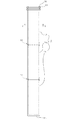
図1はこの発明のバグフィルタの1実施形態における構成を概略的に示しており、この実施形態においては、バグフィルタ10は、口元部12と、底部14と、中間部16との直列接続された3つのフィルタ部分から構成される。各フィルタ部分12, 14, 16は、バグフィルタ用途として一般的な素材にて構成することができ、一例として、ガラス繊維などの耐熱性繊維より成る糸条より織製して成る基布に、ポリテトラフルオロエチレンやポリイミド等の耐熱性繊維をニードルパンチにより植毛して構成されるフィルタ布より縫製により筒状に成形して構成することができる。筒状とするためのフィルタ布20(図5及び図6も参照)の重ね合わせによる縫製部を図2の17にて模式的に示す。図1の口元部12と中間部16との接続部及び中間部16と底部部14との接続部には本発明に係る圧嵌構造のワンタッチ式着脱自在の連接具18が設置され、フィルタ部分12, 14, 16の直列接続を実現しているが、この構成については後で詳細に説明する。 FIG. 1 schematically shows a configuration of a bug filter of the present invention in one embodiment. In this embodiment, the bug filter 10 is connected in series with a mouth portion 12, a bottom portion 14, and an intermediate portion 16. It is composed of three filter parts. Each of the filter portions 12, 14 and 16 can be made of a material common for bag filter applications, and as an example, a base cloth woven from threads made of heat-resistant fibers such as glass fibers. It can be formed by forming a tubular shape by sewing from a filter cloth formed by planting heat-resistant fibers such as polytetrafluoroethylene and polyimide by needle punching. A sewn portion formed by superimposing the filter cloth 20 (see also FIGS. 5 and 6) for forming a tubular shape is schematically shown in FIG. 2-17. A one-touch detachable connecting tool 18 having a pressure-fitting structure according to the present invention is installed at the connecting portion between the mouth portion 12 and the intermediate portion 16 and the connecting portion between the intermediate portion 16 and the bottom portion 14 in FIG. Although 12, 14, and 16 series connections are realized, this configuration will be described in detail later.

口元部12は、集塵装置のセルプレートへの取付具19を備えており、取付具19の構造としては公知の任意の手段で良いが、一例としては、本出願人になる特許文献3等と同様の構成とすることができ、図3に示すように、口元部12を構成するフィルタ布20の上端に金属製スナップリング22を包み込むように口元布24が縫糸26により縫着される。口元部12を上から押し込むことにより、スナップリング22はその外周凹部22-1において、集塵装置のセルプレート28の一つのバグフィルタ取付孔28-1にワンタッチ式に装着することができる。尚、周知のようにバグフィルタ10の筒形状を確保するため、籠形状をなし底部部14(図1)の底面付近まで延びる金属製のリテーナ30がセルプレート28の上から挿入される。 The mouth portion 12 is provided with an attachment 19 to the cell plate of the dust collector, and the structure of the attachment 19 may be any known means. As shown in FIG. 3, the mouth cloth 24 is sewn by the sewing thread 26 so as to wrap the metal snap ring 22 around the upper end of the filter cloth 20 constituting the mouth portion 12. By pushing the mouth portion 12 from above, the snap ring 22 can be mounted in the outer peripheral recess 22-1 in a one-touch manner in one bug filter mounting hole 28-1 of the cell plate 28 of the dust collector. As is well known, in order to secure the tubular shape of the bug filter 10, a metal retainer 30 having a basket shape and extending to the vicinity of the bottom surface of the bottom portion 14 (FIG. 1) is inserted from above the cell plate 28.

底部部14は、口元部12及び中間部16と同様に筒状に縫製したフィルタ布により構成されるが、周知の縫製構造による閉鎖された底面部14-1 を備えている点で相違する。また、中間部16は上下で開口した筒形状であり、図1に示す実施形態としては、一個のみ設けられるが、必要な長さが得られるように複数使用することが可能であるし、バグフィルタの必要な長さが短い場合は、図4のように、口元部12と底部部14との2つのフィルタ部分のみとし、中間部16を省略することが可能であり、これは本発明に係るバグフィルタの必要最小構成を示している。 The bottom portion 14 is composed of a filter cloth sewn in a tubular shape like the mouth portion 12 and the intermediate portion 16, except that the bottom portion 14 is provided with a closed bottom portion 14-1 having a well-known sewing structure. Further, the intermediate portion 16 has a tubular shape that is open at the top and bottom, and although only one is provided as the embodiment shown in FIG. 1, a plurality of intermediate portions 16 can be used so as to obtain a required length, and a bug. When the required length of the filter is short, as shown in FIG. 4, it is possible to use only two filter portions, the mouth portion 12 and the bottom portion 14, and omit the intermediate portion 16, which is the present invention. The minimum required configuration of the bug filter is shown.

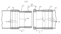
次に、フィルタ部分12, 14, 16間の連接具18の構造について説明すると、図5は分離状態における連接具18を示しており、連接具18は、隣接するフィルタ部分の一方のフィルタ部分におけるフィルタ布20に取り付けられた保持リング32(本発明の高剛性の第1の環状金属部材)と、隣接するフィルタ部分の他方のフィルタ部分におけるフィルタ布20に取り付けられたスナップリング34(本発明の第2の環状金属部材)とからなる。保持リング32は外径3mm程度の鋼線にて構成されているため剛性が高く、フィルタ部分12, 14, 16間の接続のための人力による圧入操作では殆ど変形を生じない。他方、スナップリング34は、肉厚0.3mm、幅1.9mmといった薄肉の帯状鋼材を環状に成形してなるもので、保持リング32と比較して相当に低剛性であり、人力による圧入操作時に容易に変形させることができる。スナップリング34は低剛性であってもバグフィルタの使用状態(フィルタ部分12, 14, 16の連結状態)においては、非変形の状態を維持する程度の剛性は確保している。本実施形態では保持リング32の内径とスナップリング34の外径とは166mmと同一である。しかしながら、以下説明するフィルタ部分間の着脱可能連結のための圧入操作時に、保持リング32とスナップリング34を介したフィルタ部分の対向端部間の適切な係合連接状態を得ることができるものであれば、保持リング32の内径とスナップリング34の外径とは微妙に異ならせることも可能である。例えば、保持リング32の内径に対してスナップリング34の外径を僅か大きくしても、スナップリング34の低剛性故に、スナップリング34をして保持リング32を潜り抜けさせ、スナップリング34がその弾性により本来の外径に復帰することによりフィルタ部分間のより強固な連結状態を得るようにすることもできる。また、後述のように保持リング32もスナップリング34も周囲を連接布36, 42(図5及び図6)により包囲かつ縫着されているため、保持リング32の内径よりスナップリング34の外径が僅かであれば小さくても連接布36, 42の厚みの寄与分により、保持リング32とスナップリング34を介したフィルタ部分対向端部間の必要な連接強度を確保することも可能である。尚、保持リング32及びスナップリング34は共に鋼材製であるが、高い耐熱性が必要な場合はステンレス鋼材が好適である。 Next, the structure of the connecting tool 18 between the filter portions 12, 14 and 16 will be described. FIG. 5 shows the connecting tool 18 in the separated state, and the connecting tool 18 is in one of the filter portions of the adjacent filter portions. A holding ring 32 (the first high-rigidity annular metal member of the present invention) attached to the filter cloth 20 and a snap ring 34 (the present invention) attached to the filter cloth 20 in the other filter part of the adjacent filter part. It is composed of a second annular metal member). Since the holding ring 32 is made of a steel wire having an outer diameter of about 3 mm, it has high rigidity, and hardly deforms by a manual press-fitting operation for connecting the filter portions 12, 14 and 16. On the other hand, the snap ring 34 is formed by forming a thin strip of steel having a wall thickness of 0.3 mm and a width of 1.9 mm in an annular shape, and has considerably lower rigidity than the holding ring 32. Sometimes it can be easily deformed. Even if the snap ring 34 has low rigidity, it has sufficient rigidity to maintain a non-deformed state when the bug filter is used (the filter portions 12, 14 and 16 are connected). In this embodiment, the inner diameter of the holding ring 32 and the outer diameter of the snap ring 34 are the same as 166 mm. However, during the press-fitting operation for the detachable connection between the filter portions described below, it is possible to obtain an appropriate engagement and connection state between the opposite ends of the filter portions via the holding ring 32 and the snap ring 34. If so, the inner diameter of the holding ring 32 and the outer diameter of the snap ring 34 can be slightly different from each other. For example, even if the outer diameter of the snap ring 34 is slightly larger than the inner diameter of the holding ring 32, the snap ring 34 is made to slip through the holding ring 32 due to the low rigidity of the snap ring 34, and the snap ring 34 is used. It is also possible to obtain a stronger connection state between the filter portions by returning to the original outer diameter by elasticity. Further, as described later, since the holding ring 32 and the snap ring 34 are surrounded and sewn by the connecting cloths 36 and 42 (FIGS. 5 and 6), the outer diameter of the snap ring 34 is larger than the inner diameter of the holding ring 32. Even if the amount is small, it is possible to secure the required connection strength between the opposite ends of the filter portions via the holding ring 32 and the snap ring 34 due to the contribution of the thicknesses of the connecting cloths 36 and 42. The holding ring 32 and the snap ring 34 are both made of steel, but stainless steel is preferable when high heat resistance is required.

次に、連接具18を構成する保持リング32及びスナップリング34のフィルタ布16に対する装着構造を説明すると、図5に示すように、フィルタ布20と同素材の連接布36(連接布として特化した素材のものとすることは可能である)は保持リング32を外周から巻き込むように折り返され、保持リング32に近接した折り返し部分が筒状に縫着(縫合線(縫合糸)を38にて示す)され、連接布36の部位36´(長さL)で縫着されていることが分かる。縫着部36´より連接布36の先の部分は隣接するフィルタ部分12, 14, 16の片方における筒状のフィルタ布20の端部に挿入され、縫着される(縫着部を40にて示す)。このようにしてフィルタ部分12, 14, 16を構成する濾布の端部に保持リング32を包囲しつつ強固に縫着することができる。他方、スナップリング34については、フィルタ布20と同素材又は別素材の連接布42は、スナップリング34を外周から巻き込むように折り返され、折り返し部分が筒状に縫着(縫合線(縫合糸)を44にて示す)され、連接布42の部位42´(長さL´)で縫着されていることが分かる。縫着部42´より後側の連接布42の部分は隣接するフィルタ部分12, 14, 16における筒状のフィルタ布20の端部に挿入され、縫着される(縫着糸を46にて示す)。このようにしてフィルタ部分12, 14, 16を構成する濾布の端部にスナップリング34を包囲しつつ強固に縫着することができる。 Next, the attachment structure of the holding ring 32 and the snap ring 34 constituting the connecting tool 18 to the filter cloth 16 will be described. As shown in FIG. 5, the connecting cloth 36 of the same material as the filter cloth 20 (specialized as a connecting cloth). The material is folded back so as to wrap around the holding ring 32 from the outer circumference, and the folded portion close to the holding ring 32 is sewn into a tubular shape (sewn line (suture thread) is sewn at 38. It can be seen that it is sewn at the portion 36'(length L) of the articulated cloth 36. The tip of the articulated cloth 36 from the sewn portion 36'is inserted into the end of the tubular filter cloth 20 on one of the adjacent filter portions 12, 14 and 16 and sewn (the sewn portion is set to 40). Shown). In this way, the holding ring 32 can be firmly sewn to the end of the filter cloth constituting the filter portions 12, 14 and 16 while surrounding the holding ring 32. On the other hand, regarding the snap ring 34, the articulated cloth 42 made of the same material as the filter cloth 20 or a different material is folded back so as to wrap the snap ring 34 from the outer circumference, and the folded portion is sewn into a tubular shape (suture line (suture thread)). Is shown by 44), and it can be seen that the joint cloth 42 is sewn at the portion 42'(length L'). The portion of the articulated cloth 42 behind the sewn portion 42'is inserted into the end portion of the tubular filter cloth 20 in the adjacent filter portions 12, 14 and 16 and sewn (sewing thread at 46). show). In this way, the snap ring 34 can be firmly sewn to the end of the filter cloth constituting the filter portions 12, 14 and 16 while surrounding the snap ring 34.

次に、連接具18による隣接するフィルタ部分12, 14, 16の連結動作を説明すると、連結するフィルタ部分の端部における保持リング32とスナップリング34とを対向させる。本実施形態では、前述のように、スナップリング34は外径が保持リング32の内径と同一であるが、周囲を包囲する連接布42の厚みまで考慮すると外径は、連接布36を含めた保持リング32の内径より大きくなっているが、スナップリング34が適度な可撓性を持っているため、半径内方に凹ませつつスナップリング34側のフィルタ部分の端部に押し込んでゆくことにより、図6に示すようにスナップリング34は保持リング32を潜り抜けさせ、保持リング32及びスナップリング34を介したフィルタ部分12, 14, 16の対向端部間の係合・圧嵌状態を得ることができる。この圧嵌状態では、片側のフィルタ部分のスナップリング34は、相手側のフィルタ部分の縫着部分36´において、弾性により本来の外径まで復帰拡開される。スナップリング34が縫着部分36´に丁度収まるように、スナップリング34の軸長に対する縫着部分36´の軸長L(図5)が設定されている。他方、保持リング32はその高剛性により装着工程を通じてその内径を維持し、図6の嵌着状態ではスナップリング32は、片側のフィルタ部分の連接布42の縫着部分42´を半径内方に屈曲させるようになっている。縫着部分42´の長さL´(図5)は縫着部分42´が図6に示すように屈曲されても、フィルタ布20の部位においては本来の径に戻るように設定されている。このような、本発明に係る保持リング32とスナップリング34によるフィルタ部分間の連結は強固でありかつ流密を確保することができる。即ち、スナップリング34の帯状素材で形成され、接続部における連接布36, 42の接触長さが圧嵌長となるが、これは基本的にはスナップリング34を構成する金属帯材の幅により決まる。そして、接触長を必要分十分長く取れるため、流密が確保され、バグフィルタの通常の動作において被処理ガスが漏洩することはなく、また保持リング32とスナップリング34を介したフィルタ部分12, 14, 16の端部間の係合状態は、人力による単純な引張り力に対しては強力であり、逆洗時にバグフィルタの内部にパルス圧を加えた状態においてもフィルタ部分間の離脱が生ずることを確実防止することを可能とする。 Next, the operation of connecting the adjacent filter portions 12, 14 and 16 by the connecting tool 18 will be described. The holding ring 32 and the snap ring 34 at the ends of the connected filter portions are opposed to each other. In the present embodiment, as described above, the outer diameter of the snap ring 34 is the same as the inner diameter of the holding ring 32, but the outer diameter includes the connecting cloth 36 in consideration of the thickness of the connecting cloth 42 surrounding the snap ring 34. Although it is larger than the inner diameter of the holding ring 32, since the snap ring 34 has appropriate flexibility, it is pushed into the end of the filter portion on the snap ring 34 side while being recessed inward in the radius. , As shown in FIG. 6, the snap ring 34 slips through the holding ring 32 to obtain an engaged / press-fitted state between the facing ends of the filter portions 12, 14 and 16 via the holding ring 32 and the snap ring 34. be able to. In this press-fitting state, the snap ring 34 of the filter portion on one side is elastically restored and expanded to the original outer diameter at the sewn portion 36'of the filter portion on the other side. The shaft length L (FIG. 5) of the sewn portion 36'is set with respect to the shaft length of the snap ring 34 so that the snap ring 34 fits exactly in the sewn portion 36'. On the other hand, the holding ring 32 maintains its inner diameter throughout the mounting process due to its high rigidity, and in the fitted state of FIG. It is designed to bend. The length L'(FIG. 5) of the sewn portion 42'is set so as to return to the original diameter at the portion of the filter cloth 20 even if the sewn portion 42'is bent as shown in FIG. .. Such a connection between the holding ring 32 and the filter portion by the snap ring 34 according to the present invention is strong and airtightness can be ensured. That is, it is formed of the strip-shaped material of the snap ring 34, and the contact length of the connecting cloths 36 and 42 at the connecting portion is the press fitting length, which basically depends on the width of the metal strip material constituting the snap ring 34. It is decided. Since the contact length can be made sufficiently long as necessary, airtightness is ensured, the gas to be processed does not leak in the normal operation of the bug filter, and the filter portion 12, via the holding ring 32 and the snap ring 34, The engagement state between the ends of 14 and 16 is strong against a simple tensile force by human power, and even when a pulse pressure is applied to the inside of the bag filter during backwashing, the filter parts are separated from each other. It is possible to surely prevent this.

フィルタ部分12, 14, 16の分離時は、スナップリング34に半径内方に外力を加えることで、スナップリング34を凹ませつつ両者を離間方向に引張ることによりスナップリング34をして保持リング32を潜り抜けさせることができ、これによりフィルタ部分12, 14, 16の分離が行なわれる。 When the filter portions 12, 14 and 16 are separated, an external force is applied to the snap ring 34 inward in the radius to dent the snap ring 34 and pull the two in the separating direction to form the snap ring 34 and hold the ring 32. Can be slipped through, which separates the filter portions 12, 14, and 16.

本発明においては、バグフィルタを複数のフィルタ部分12, 14, 16により構成し、フィルタ部分12, 14, 16間を脱着可能な連接具18により連接することにより、継ぎ足しによるバグフィルタの長尺化が容易に可能である。即ち、図1において、口元部12と底部部14は必須であるが(図4は口元部12と底部部14とを連接具18で接続した最小構成を示す)、長さを継ぎ足したい場合は、中間部16を必要長さ若しくは必要枚数数継ぎ足すことによりバグフィルタの全長を所望の値とすることができる。また、フィルタ部分12, 14, 16のうちの一部のフィルタ部分の機能が低下した場合に、機能が低下したフィルタ部分のみを交換することが容易に可能である。 In the present invention, the bug filter is composed of a plurality of filter portions 12, 14, 16 and the filter portions 12, 14, 16 are connected by a detachable connecting tool 18, so that the bug filter is lengthened by addition. Is easily possible. That is, in FIG. 1, the mouth portion 12 and the bottom portion 14 are indispensable (FIG. 4 shows the minimum configuration in which the mouth portion 12 and the bottom portion 14 are connected by the connecting tool 18), but when the length is desired to be added. The total length of the bug filter can be set to a desired value by adding the required length or the required number of sheets of the intermediate portion 16. Further, when the function of some of the filter portions 12, 14 and 16 is deteriorated, it is easily possible to replace only the deteriorated filter portion.

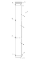
また、本発明の別実施形態として、バグフィルタ各部の完全モジュール化(規格品化)が可能である。即ち、図1のセルプレート取付具19及びフィルタ底部14-1も単独でモジュール化し、これをモジュール化した必要数の中間部にて一連連結する構成とすることができる。即ち、図7に示すようにこの実施形態のバグフィルタ50は口元モジュール52と、底部モジュール54と、3個の中間モジュール56とからなり、これらのモジュール52, 54, 56とは同一径のセルプレートに対して規格化されている。口元モジュール52は、セルプレートに対する取付部19を設けた短いものであり、底部モジュール54も閉鎖底面54-1を設けただけの短いものである。中間モジュール56は規格化され、一定長であり、必要なバグフィルタ長が得られる個数が使用される。モジュール52, 54, 56間の接続は本発明の接続具18(図5及び図6)によりワンタッチ式に着脱自在となっている。規格化されたモジュール52, 54, 56はストックしておき、注文のフィルタ長さより決まる数の中間モジュール56を口元モジュール52及び底部モジュール54と直列接続することにより、どのような長さのバグフィルタであってもユーザに即納することが可能となる。 Further, as another embodiment of the present invention, each part of the bug filter can be completely modularized (standardized). That is, the cell plate attachment 19 and the filter bottom 14-1 of FIG. 1 can also be modularized independently, and can be connected in series at the required number of modularized intermediate portions. That is, as shown in FIG. 7, the bug filter 50 of this embodiment includes a mouth module 52, a bottom module 54, and three intermediate modules 56, and these modules 52, 54, 56 have cells having the same diameter. Standardized for plates. The mouth module 52 is a short one provided with a mounting portion 19 for the cell plate, and the bottom module 54 is also a short one provided with a closed bottom surface 54-1. The intermediate module 56 is standardized and has a constant length, and the number of intermediate modules 56 that can obtain the required bug filter length is used. The connection between the modules 52, 54, and 56 is one-touch detachable by the connector 18 (FIGS. 5 and 6) of the present invention. By stocking the standardized modules 52, 54, 56 and connecting the number of intermediate modules 56 determined by the ordered filter length in series with the mouth module 52 and the bottom module 54, a bug filter of any length can be used. Even so, it is possible to deliver to the user immediately.

図8はモジュール化構造の別実施形態を示し、セルプレートにマイクロバンドで取り付けるタイプのバグフィルタ50aを示す。この実施形態において、バグフィルタ50aのモジュール化された底部モジュール54と中間モジュール56(図では3個であるがバグフィルタの必要長さに応じた個数となっている)は図7の実施形態と同様であるが、口元モジュール52aはマイクロバンド70によりセルプレート28aに取り付ける方式のものである。マイクロバンド70によるセルプレート28aへの取付構造の場合、セルプレート28aはバグフィルタの取り付けのための下向き筒状取付部28a-1を備えており、バグフィルタ50aの口元モジュール52aにおける濾布部分は、図9に示すように、セルプレート28aの筒状取付部28a-1に挿入され、マイクロバンド70により固定される。マイクロバンド70は、いくつかのタイプのものが公知であるが、この実施形態においては、図9に示すように薄肉帯状金属にて形成された締結バンド72と締結バンド72の各端部に溶接固定された一対のラグ74, 76と、止めねじ78とを備え、止めねじ78は片方のラグ76にフリーに挿通され、止めねじ78の先端ねじ部78-1が対向したラグ74に螺合される。止めねじ78の頭部のナット部78-2を回して行くことにより締結バンド72が締まり、セルプレート28aの筒状取付部28a-1へのバグフィルタ50aの取付を行なうことができる。 FIG. 8 shows another embodiment of the modularized structure, and shows a bug filter 50a of a type attached to a cell plate with a micro band. In this embodiment, the modularized bottom module 54 and the intermediate module 56 of the bug filter 50a (three in the figure, but the number corresponds to the required length of the bug filter) are the same as those in the embodiment of FIG. Similarly, the mouth module 52a is attached to the cell plate 28a by the micro band 70. In the case of the mounting structure to the cell plate 28a by the micro band 70, the cell plate 28a is provided with a downward tubular mounting portion 28a-1 for mounting the bug filter, and the filter cloth portion in the mouth module 52a of the bug filter 50a is , As shown in FIG. 9, it is inserted into the tubular mounting portion 28a-1 of the cell plate 28a and fixed by the micro band 70. Several types of the micro band 70 are known, but in this embodiment, as shown in FIG. 9, the fastening band 72 formed of a thin-walled strip metal and the fastening band 72 are welded to each end. A pair of fixed lugs 74, 76 and a set screw 78 are provided, and the set screw 78 is freely inserted into one lug 76, and the tip thread portion 78-1 of the set screw 78 is screwed into the opposite lug 74. Will be done. By turning the nut portion 78-2 of the head of the set screw 78, the fastening band 72 is tightened, and the bug filter 50a can be attached to the tubular attachment portion 28a-1 of the cell plate 28a.

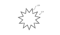
図10は本発明の別実施形態を示しており、この実施形態においても、図1の実施形態と同様に、バグフィルタ110は、口元部112と、底部114と、中間部116との直列接続された3つのフィルタ部分112, 114, 116から構成され、フィルタ部分112, 114, 116間を直列にかつ離脱可能に嵌着方式にて連結する連接具118を備える。連接具118の構成は図5及び図6で説明した連接具18と同様に構成可能である。相違点は、この実施形態にといては、フィルタ部分112, 114, 116を構成するフィルタ布120(図11及び図12)はプリーツを形成している点が相違する。バグフィルタ用濾布のプリーツ形成については各種提案されており、適宜の方法を採用でき、一例を上げれば、周知の本出願人と同一出願人に係る特許文献2の明細書に記載のように行なうことができる。即ち、プレーンな濾布はプリーツ成形機を通すことによりプリーツ形状に賦形され、プリーツ形状を保持するためプリーツの山及び谷を縫製により強化することができる。また、別のプリーツ形状賦与方式としては、特許文献3のように濾布に熱硬化樹脂を含浸させた形でプリーツ成形機を通し、プリーツ賦与の際に、樹脂の熱硬化温度まで加熱も同時に行なうことにより、プリーツ形状を保持するようにすることもできる。尚、図10の実施形態において、連接具118との接続部位120’においてはフィルタ布120を縫製により平坦状に潰すことで(特許文献3)、図5の連接布36, 42とのスムースな連接(縫着)が可能となる。 FIG. 10 shows another embodiment of the present invention. In this embodiment as well, the bug filter 110 is connected in series with the mouth portion 112, the bottom portion 114, and the intermediate portion 116, as in the embodiment of FIG. It is composed of three filter portions 112, 114, 116, and is provided with a connecting tool 118 that connects the filter portions 112, 114, 116 in series and in a detachable manner by a fitting method. The configuration of the connecting tool 118 can be configured in the same manner as the connecting tool 18 described with reference to FIGS. 5 and 6. The difference is that, in this embodiment, the filter cloth 120 (FIGS. 11 and 12) constituting the filter portions 112, 114, 116 forms pleats. Various proposals have been made for the formation of pleats for the bag filter filter cloth, and an appropriate method can be adopted. For example, as described in the specification of Patent Document 2 relating to the same applicant as the well-known applicant. Can be done. That is, the plain filter cloth is shaped into a pleated shape by passing it through a pleating machine, and the pleated peaks and valleys can be reinforced by sewing in order to maintain the pleated shape. Further, as another pleated shape imparting method, as in Patent Document 3, the filter cloth is impregnated with a thermosetting resin and passed through a pleating molding machine, and when the pleats are imparted, the resin is heated to the thermosetting temperature at the same time. By doing so, it is also possible to maintain the pleated shape. In the embodiment of FIG. 10, at the connection portion 120'with the connecting tool 118, the filter cloth 120 is crushed flat by sewing (Patent Document 3), so that the connecting cloths 36 and 42 of FIG. 5 can be smoothly crushed. It is possible to connect (sewing).

図10の実施形態においても、本発明により、フィルタ部分112, 114, 116間の連接具118による離脱可能嵌着構造により、プリーツ構造のバグフィルタにおいても継ぎ足しによる長さ調製が簡易に可能となる。また、フィルタ部分毎の交換も簡便に実施することができる。本発明をプリーツ構造に採用した場合の効果として、フィルタ部分112, 114, 116間でプリーツの山数を変化させることができる。例えば、バグフィルタでは底部側でのダストの捕集量が少なくなるため、このフィルタ部分114でプリーツの山数(図12)を他のフィルタ部分112, 116(図11)より少なくすることで、コストダウンを実現しつつトータルでの捕集効率は維持することができる。 Also in the embodiment of FIG. 10, according to the present invention, the detachable fitting structure by the connecting tool 118 between the filter portions 112, 114, 116 makes it possible to easily adjust the length by replenishment even in the bug filter having a pleated structure. .. In addition, it is possible to easily replace each filter portion. As an effect when the present invention is adopted in the pleated structure, the number of pleated peaks can be changed between the filter portions 112, 114, 116. For example, since the amount of dust collected on the bottom side of the bug filter is small, the number of pleats (FIG. 12) in this filter portion 114 can be reduced compared to the other filter portions 112 and 116 (FIG. 11). The total collection efficiency can be maintained while achieving cost reduction.

また、プリーツ構造以外にも、濾材をヒダ折りし円筒状に構成したフィルタ構造のものについても本発明の思想は同様に適用可能である。 Further, in addition to the pleated structure, the idea of the present invention can be similarly applied to a filter structure in which a filter medium is folded into a fold to form a cylindrical shape.

10, 110…バグフィルタ
12, 112…口元部
14, 114…底部
16, 116…中間部
18, 118…連接具
19…セルプレート取付具
20, 120…フィルタ布
28…セルプレート
32…保持リング(本発明の第1の環状金属部材)
34…スナップリング(本発明の第2の環状金属部材)
36, 42…連接布
36’, 42’… 連接布の縫着部分
38, 40, 44, 46…縫合線
50, 50a…規格化されたバグフィルタ
52…口元モジュール
54…底部モジュール
56…中間モジュール
70…マイクロバンド
10, 110… Bug filter
12, 112… Mouth
14, 114… bottom
16, 116… Middle part
18, 118 ... Connecting tool 19 ... Cell plate mounting tool
20, 120 ... Filter cloth 28 ... Cell plate 32 ... Holding ring (first annular metal member of the present invention)
34 ... Snap ring (second annular metal member of the present invention)
36, 42… Articulated cloth
36', 42'… Sewn part of the articulated cloth
38, 40, 44, 46… Suture line
50, 50a ... Standardized bug filter 52 ... Mouth module 54 ... Bottom module 56 ... Intermediate module 70 ... Microband

Claims (3)

バグフィルタの構造であって、バグフィルタの少なくとも一部が着脱可能な連接具によって直列接続して構成され、バグフィルタが少なくとも部分的に交換可能とされ、前記連接具は、連接すべきフィルタの隣接部位における一方側の高剛性の第1の環状部材と、他方側の低剛性の第2の環状部材とを具備して構成され、連接具によるフィルタの前記隣接部位の直列接続は、高剛性の第1の環状部材に対する低剛性の第2の環状部材の半径内方の弾性変形下高剛性の第1の環状部材に対し低剛性の第2の環状部材のバグフィルタ長手方向の潜り抜けによる第1の環状部材と第2の環状部材を介してのフィルタの隣接部位間のバグフィルタ長手方向の係合により行われ、前記第1の環状部材は、金属を素材とし隣接するフィルタ隣接部位の片側におけるフィルタ布に取り付けられ、前記第2の環状部材は、金属を素材としフィルタ隣接部位の反対側におけるフィルタ布に取り付けられ、フィルタの隣接部位の直列接続は、夫々のフィルタ布を介しての第1の環状部材と第2の環状部材との係合により行われ、前記第1の環状部材は実質的に円形断面のリング状をなし、第1の連接布に包着されており、第1の連接布は隣接するフィルタ部分の片側におけるフィルタ布の端部に縫着されており、前記第2の環状部材は薄肉の帯状素材を環状に成形して成りかつ第2の連接布に包着されており、第2の連接布は隣接するフィルタ部分の反対側におけるフィルタ布の端部に縫着されているバグフィルタ。 The structure of the bug filter, in which at least a part of the bug filter is connected in series by a detachable connecting tool, the bug filter is at least partially replaceable, and the connecting tool is of a filter to be connected. A first annular member having high rigidity on one side and a second annular member having low rigidity on the other side at the adjacent portion are provided, and the series connection of the adjacent portions of the filter by the connecting tool has high rigidity. Due to elastic deformation inward of the radius of the second annular member having low rigidity with respect to the first annular member of the This is performed by engaging the bag filter in the longitudinal direction between the adjacent portion of the filter via the first annular member and the second annular member, and the first annular member is made of metal and is adjacent to the filter. Attached to the filter cloth on one side, the second annular member is made of metal and is attached to the filter cloth on the opposite side of the filter adjacent part, and the series connection of the filter adjacent parts is made through the respective filter cloths. It is performed by engaging the first annular member and the second annular member, and the first annular member has a substantially circular ring shape and is wrapped in the first articulated cloth. The articulated cloth of 1 is sewn to the end of the filter cloth on one side of the adjacent filter portion, and the second annular member is formed by forming a thin strip-shaped material into an annular shape and wrapped in the second articulated cloth. A bug filter that is worn and the second articulated cloth is sewn to the edge of the filter cloth on the opposite side of the adjacent filter portion. 請求項1に記載の発明において、バグフィルタは、複数のフィルタ部分に分割され、前記着脱可能な連接具は隣接するフィルタ部分間を着脱自在に連結したバグフィルタ。 In the invention according to claim 1, the bug filter is divided into a plurality of filter portions, and the detachable connecting tool is a bug filter in which adjacent filter portions are detachably connected. 請求項に記載の発明において、バグフィルタは、バグフィルタの全体を構成する各フィルタ部分がモジュール化されたバグフィルタ。 In the invention according to claim 2 , the bug filter is a bug filter in which each filter portion constituting the entire bug filter is modularized.
JP2017169154A 2017-09-04 2017-09-04 Bug filter Active JP6928374B2 (en)

Priority Applications (1)

Application Number Priority Date Filing Date Title
JP2017169154A JP6928374B2 (en) 2017-09-04 2017-09-04 Bug filter

Applications Claiming Priority (1)

Application Number Priority Date Filing Date Title
JP2017169154A JP6928374B2 (en) 2017-09-04 2017-09-04 Bug filter

Publications (3)

Publication Number Publication Date
JP2019042677A JP2019042677A (en) 2019-03-22
JP2019042677A5 JP2019042677A5 (en) 2020-08-20
JP6928374B2 true JP6928374B2 (en) 2021-09-01

Family

ID=65813387

Family Applications (1)

Application Number Title Priority Date Filing Date
JP2017169154A Active JP6928374B2 (en) 2017-09-04 2017-09-04 Bug filter

Country Status (1)

Country Link
JP (1) JP6928374B2 (en)

Families Citing this family (1)

* Cited by examiner, † Cited by third party
Publication number Priority date Publication date Assignee Title
JP7218905B2 (en) * 2019-01-24 2023-02-07 株式会社相模商会 Bag filter connector

Family Cites Families (6)

* Cited by examiner, † Cited by third party
Publication number Priority date Publication date Assignee Title
JPS4840200Y1 (en) * 1969-06-14 1973-11-26
JPS5055972A (en) * 1973-09-19 1975-05-16
JPS57177520U (en) * 1981-05-08 1982-11-10
JPS58151420U (en) * 1982-04-06 1983-10-11 泉株式会社 "Ro" tube for unit type dust collector
US6375698B1 (en) * 1998-09-30 2002-04-23 Bha Group Holdings, Inc. Long filter assembly with connection device
JP2009011989A (en) * 2007-07-09 2009-01-22 Techno M:Kk Molded filter

Also Published As

Publication number Publication date
JP2019042677A (en) 2019-03-22

Similar Documents

Publication Publication Date Title
EP1813342B2 (en) Filter element and filter system, in particular for the intake air of a combustion engine
US4015961A (en) Filter bag and coupling
CN103168162B (en) Fuel filter
US20160243481A1 (en) Embossed fluid filter treatment
JP6928374B2 (en) Bug filter
EP1794439A2 (en) Filter element
KR100593294B1 (en) Method of assembling a filter element with structurally attached outer sleeve
EP2722092A1 (en) Air filter with tensile support member
KR101823731B1 (en) Hybrid Pleated Filter Bag
CN107398113A (en) Filter for installation
CN107617248B (en) Corrugated filter media with modulated corrugations
JP2009011989A (en) Molded filter
KR20130002819U (en) Tubing conjunction structuer for water purifying filter
JP2021186781A (en) Bag filter
KR20130094435A (en) Filter bag for dust cleaner
KR102041713B1 (en) Filter bag for dust collector and manufacturing method thereof
JP4379529B1 (en) Water purification cartridge
JP2020116529A (en) Connector for bag filter
JP5139938B2 (en) Actuator
DE102005041037A1 (en) Oil filter arrangement
JP7048081B2 (en) Bug filter
JP6674823B2 (en) Cylindrical filter
JP2010259978A (en) Bag filter
KR20150135184A (en) Filter for dust collector
JP7020879B2 (en) Fitting caps and fittings

Legal Events

Date Code Title Description
A521 Written amendment

Free format text: JAPANESE INTERMEDIATE CODE: A523

Effective date: 20171006

A521 Written amendment

Free format text: JAPANESE INTERMEDIATE CODE: A523

Effective date: 20200710

A621 Written request for application examination

Free format text: JAPANESE INTERMEDIATE CODE: A621

Effective date: 20200710

A977 Report on retrieval

Free format text: JAPANESE INTERMEDIATE CODE: A971007

Effective date: 20210518

A131 Notification of reasons for refusal

Free format text: JAPANESE INTERMEDIATE CODE: A131

Effective date: 20210521

A521 Written amendment

Free format text: JAPANESE INTERMEDIATE CODE: A523

Effective date: 20210610

TRDD Decision of grant or rejection written
A01 Written decision to grant a patent or to grant a registration (utility model)

Free format text: JAPANESE INTERMEDIATE CODE: A01

Effective date: 20210727

A61 First payment of annual fees (during grant procedure)

Free format text: JAPANESE INTERMEDIATE CODE: A61

Effective date: 20210730

R150 Certificate of patent or registration of utility model

Ref document number: 6928374

Country of ref document: JP

Free format text: JAPANESE INTERMEDIATE CODE: R150