JP6928182B1 - Stop cause identification support device, stop cause identification support program and method - Google Patents
Stop cause identification support device, stop cause identification support program and method Download PDFInfo
- Publication number
- JP6928182B1 JP6928182B1 JP2020535674A JP2020535674A JP6928182B1 JP 6928182 B1 JP6928182 B1 JP 6928182B1 JP 2020535674 A JP2020535674 A JP 2020535674A JP 2020535674 A JP2020535674 A JP 2020535674A JP 6928182 B1 JP6928182 B1 JP 6928182B1
- Authority
- JP
- Japan
- Prior art keywords
- stop
- time
- data
- influence
- error
- Prior art date
- Legal status (The legal status is an assumption and is not a legal conclusion. Google has not performed a legal analysis and makes no representation as to the accuracy of the status listed.)
- Active
Links
- 238000000034 method Methods 0.000 title claims abstract description 479
- 230000008569 process Effects 0.000 claims abstract description 463
- 238000004519 manufacturing process Methods 0.000 claims abstract description 79
- 238000004364 calculation method Methods 0.000 claims abstract description 30
- 238000003860 storage Methods 0.000 claims abstract description 27
- 230000000694 effects Effects 0.000 claims abstract description 26
- 230000010365 information processing Effects 0.000 claims description 25
- 230000000644 propagated effect Effects 0.000 abstract description 13
- 239000000047 product Substances 0.000 description 58
- 238000004891 communication Methods 0.000 description 17
- 238000010586 diagram Methods 0.000 description 11
- 238000001514 detection method Methods 0.000 description 8
- 238000004886 process control Methods 0.000 description 8
- 238000011144 upstream manufacturing Methods 0.000 description 8
- 230000007704 transition Effects 0.000 description 6
- 239000000725 suspension Substances 0.000 description 4
- 230000005856 abnormality Effects 0.000 description 3
- 230000003111 delayed effect Effects 0.000 description 3
- 230000002093 peripheral effect Effects 0.000 description 3
- 230000001902 propagating effect Effects 0.000 description 3
- 238000010276 construction Methods 0.000 description 2
- 239000000463 material Substances 0.000 description 2
- 238000004088 simulation Methods 0.000 description 2
- 230000009471 action Effects 0.000 description 1
- 238000004220 aggregation Methods 0.000 description 1
- 230000002776 aggregation Effects 0.000 description 1
- 238000004458 analytical method Methods 0.000 description 1
- 238000004140 cleaning Methods 0.000 description 1
- 230000001934 delay Effects 0.000 description 1
- 238000011143 downstream manufacturing Methods 0.000 description 1
- 239000012467 final product Substances 0.000 description 1
- 230000006870 function Effects 0.000 description 1
- 239000007787 solid Substances 0.000 description 1
- 238000006467 substitution reaction Methods 0.000 description 1
Images


Classifications
-
- G—PHYSICS
- G05—CONTROLLING; REGULATING
- G05B—CONTROL OR REGULATING SYSTEMS IN GENERAL; FUNCTIONAL ELEMENTS OF SUCH SYSTEMS; MONITORING OR TESTING ARRANGEMENTS FOR SUCH SYSTEMS OR ELEMENTS
- G05B19/00—Programme-control systems
- G05B19/02—Programme-control systems electric
- G05B19/418—Total factory control, i.e. centrally controlling a plurality of machines, e.g. direct or distributed numerical control [DNC], flexible manufacturing systems [FMS], integrated manufacturing systems [IMS], computer integrated manufacturing [CIM]
-
- Y—GENERAL TAGGING OF NEW TECHNOLOGICAL DEVELOPMENTS; GENERAL TAGGING OF CROSS-SECTIONAL TECHNOLOGIES SPANNING OVER SEVERAL SECTIONS OF THE IPC; TECHNICAL SUBJECTS COVERED BY FORMER USPC CROSS-REFERENCE ART COLLECTIONS [XRACs] AND DIGESTS
- Y02—TECHNOLOGIES OR APPLICATIONS FOR MITIGATION OR ADAPTATION AGAINST CLIMATE CHANGE
- Y02P—CLIMATE CHANGE MITIGATION TECHNOLOGIES IN THE PRODUCTION OR PROCESSING OF GOODS
- Y02P90/00—Enabling technologies with a potential contribution to greenhouse gas [GHG] emissions mitigation
- Y02P90/02—Total factory control, e.g. smart factories, flexible manufacturing systems [FMS] or integrated manufacturing systems [IMS]
Landscapes
- Engineering & Computer Science (AREA)
- General Engineering & Computer Science (AREA)
- Manufacturing & Machinery (AREA)
- Quality & Reliability (AREA)
- Physics & Mathematics (AREA)
- General Physics & Mathematics (AREA)
- Automation & Control Theory (AREA)
- General Factory Administration (AREA)
- Management, Administration, Business Operations System, And Electronic Commerce (AREA)
Abstract
ボトルネック工程に停止の影響が伝搬したか否かに係わらず、自工程による原因により停止した工程、その停止の他の工程への影響をユーザが確認可能にする停止原因特定支援装置、停止原因特定支援プログラムおよび方法を提供する。本発明を適用した停止原因特定支援装置(14)は、生産ラインに存在する工程毎に、該工程用に設置された機器の動作状況を示す情報である動作状況情報を記憶する記憶部(141)と、動作状況情報を基に、生産ラインに存在する複数の工程のうち、他の工程を原因とせずに、動作開始後に停止した工程である第1の停止工程、及び第1の停止工程での停止により、動作開始後に停止した最後の工程である第2の停止工程を特定する工程特定部と、第1の停止工程毎に、第2の停止工程で発生した停止に及ぼしたと推定される時間を影響時間として算出する時間算出部(145)と、を備える。Regardless of whether or not the effect of the stop has propagated to the bottleneck process, the process stopped due to the cause of the own process, the stop cause identification support device that allows the user to confirm the effect of the stop on other processes, and the cause of the stop Provide specific support programs and methods. The stop cause identification support device (14) to which the present invention is applied is a storage unit (141) that stores operation status information which is information indicating the operation status of the equipment installed for each process existing in the production line. ) And the first stop process and the first stop process, which are the processes stopped after the start of operation without causing other processes among the plurality of processes existing in the production line based on the operation status information. It is presumed that the stop at the process affected the process identification unit that specifies the second stop process, which is the last process stopped after the start of operation, and the stop that occurred in the second stop process for each first stop process. It is provided with a time calculation unit (145) for calculating the time of influence as an influence time.
Description
本発明は、複数の工程が存在する生産ラインを想定した停止原因特定支援装置、停止原因特定支援プログラムおよび方法に関する。 The present invention relates to a stop cause identification support device, a stop cause identification support program, and a method assuming a production line in which a plurality of processes exist.
工場等では、製品の生産のために、生産ラインが構築される。この生産ラインには、通常、複数の工程が存在する。大部分の工程には、割り当てられた作業用に一つ以上の機器が配置される。予め定められた順序で各工程の作業が行われることにより、製品が生産される。そのために、生産ラインによる製品の生産では、一つの工程で発生した停止の影響は、少なくとも、その工程より下流側の工程に伝搬する。 At factories, etc., production lines are constructed for the production of products. This production line usually has a plurality of processes. Most processes are equipped with one or more devices for the assigned work. A product is produced by performing the work of each process in a predetermined order. Therefore, in the production of products by the production line, the effect of the stoppage generated in one process propagates to at least the process downstream from that process.
下流側に影響が伝搬することから、何れかの工程に停止が発生した場合、その停止への対策を検討するためには、停止が発生した工程のうちで最上流に位置する工程を特定する必要がある。このことから、従来の停止原因特定支援装置としては、各工程に配置された機器に発生した事象を検知し、1つの機器の停止を検知した後、ボトルネック工程の機器の停止を検知した場合に、その1つの機器の停止の影響がボトルネック工程の機器に伝搬したと判定するものがある(例えば、特許文献1参照)。ここで、ボトルネック工程とは、所要時間が最も長い工程のことである。 Since the effect propagates to the downstream side, if a stop occurs in any of the processes, in order to consider countermeasures for the stop, identify the most upstream process among the processes in which the stop occurred. There is a need. From this, as a conventional stop cause identification support device, when an event occurring in a device arranged in each process is detected, a stop of one device is detected, and then a stop of a device in a bottleneck process is detected. In some cases, it is determined that the effect of stopping one of the devices has propagated to the device in the bottleneck process (see, for example, Patent Document 1). Here, the bottleneck process is the process that takes the longest time.
上記従来の停止原因特定支援装置は、一つの機器が停止した場合、その機器の工程より下流側、或いは上流側の各工程を対象に、ワークの投入待ち、或いはワークの払出待ちが発生したか否か順次、確認していくようになっている。それにより、従来の停止原因特定支援装置は、1つの機器の停止がボトルネック工程の機器に伝搬したか否か判定している。そのため、ユーザは、ボトルネック工程を停止させる根本的な原因が発生した工程、言い換えれば自工程のみの原因によって停止し、その停止がボトルネック工程に伝搬した工程を確認することができる。 In the above-mentioned conventional stop cause identification support device, when one device is stopped, is there a waiting for work loading or a waiting for work withdrawal for each process on the downstream side or upstream side of the process of the device? Whether or not it is being confirmed in sequence. As a result, the conventional stop cause identification support device determines whether or not the stop of one device has propagated to the device in the bottleneck process. Therefore, the user can confirm the process in which the root cause of stopping the bottleneck process is generated, in other words, the process is stopped only by the cause of the own process, and the stop is propagated to the bottleneck process.
ボトルネック工程に着目していることから、従来の停止原因特定支援装置では、ユーザは、ボトルネック工程に影響が伝搬しない工程で発生した停止、その停止が伝搬する範囲を確認することができない。従って、ユーザは、根本的な原因により停止した工程、その停止の影響が及ぶ範囲を必ずしも確認することはできない。 Since the focus is on the bottleneck process, the user cannot confirm the stop that occurred in the process in which the influence does not propagate to the bottleneck process and the range in which the stop propagates in the conventional stop cause identification support device. Therefore, the user cannot always confirm the process stopped due to the root cause and the range affected by the stop.
停止の発生を想定しての単位時間当たりの生産ラインが生産可能な製品数をより向上させるためには、1つの工程で発生した停止の影響をより抑える必要がある。このこともあり、ボトルネック工程に停止の影響が伝搬したか否かに係わらず、根本的な原因により停止した工程、その停止の他の工程への影響をユーザが確認できるようにすることも必要と思われる。 In order to further improve the number of products that can be produced by the production line per unit time assuming the occurrence of a stop, it is necessary to further suppress the influence of the stop that occurs in one process. For this reason, it is also possible for the user to confirm the process stopped due to the root cause and the effect of the stop on other processes regardless of whether or not the effect of the stop has propagated to the bottleneck process. It seems necessary.
本発明は、ボトルネック工程に停止の影響が伝搬したか否かに係わらず、自工程による原因により停止した工程、その停止の他の工程への影響をユーザが確認可能にする停止原因特定支援装置、停止原因特定支援プログラムおよび方法を提供することを目的とする。 The present invention provides stop cause identification support that enables the user to confirm the process stopped due to the cause of the own process and the effect of the stop on other processes regardless of whether or not the effect of the stop is propagated to the bottleneck process. The purpose is to provide equipment, stop cause identification support programs and methods.
本発明に係る停止原因特定支援装置は、生産ラインに存在する工程毎に、該工程用に設置された機器の動作状況を示す情報である動作状況情報を記憶する記憶部と、動作状況情報を基に、生産ラインに存在する複数の工程のうち、他の工程を原因とせずに、動作開始後に停止した工程である第1の停止工程、及び第1の停止工程での停止により、動作開始後に途中停止した最後の工程である第2の停止工程を特定する工程特定部と、第2の停止工程に対して複数の第1の停止工程が特定された場合に、第2の停止工程で発生した停止に各第1の停止工程が及ぼしたと推定される時間をそれぞれ影響時間とし、影響時間の合計の上限を第2の停止工程が停止した時間として、影響時間を第1の停止工程毎に算出する時間算出部と、を備える。 The stop cause identification support device according to the present invention has a storage unit that stores operation status information, which is information indicating the operation status of the equipment installed for the process, and operation status information for each process existing in the production line. Based on this, of the plurality of processes existing in the production line, the operation is started by the first stop process, which is a process stopped after the start of the operation, and the stop in the first stop process, without causing any other process. In the second stop process, when a process specifying unit that specifies the second stop process, which is the last process that was stopped halfway later, and a plurality of first stop processes are specified for the second stop process. generated stop time that each first stop process is estimated to have had were respectively influence time, the maximum amount of combined influence time as a second time stopping step stops, the first for each stopping step the influence time It is provided with a time calculation unit for calculating.
本発明に係る停止原因特定支援プログラムは、生産ラインに存在する工程毎に、該工程用に設置された機器の動作状況を示す情報である動作状況情報を参照して、生産ラインに存在する複数の工程のうち、他の工程を原因とせずに、動作開始後に停止した工程である第1の停止工程、及び第1の停止工程での停止により、動作開始後に途中停止した最後の工程である第2の停止工程を特定し、第2の停止工程に対して複数の第1の停止工程が特定された場合に、第2の停止工程で発生した停止に各第1の停止工程が及ぼしたと推定される時間をそれぞれ影響時間とし、影響時間の合計の上限を第2の停止工程が停止した時間として、影響時間を第1の停止工程毎に算出する。 The stop cause identification support program according to the present invention refers to a plurality of stop cause identification support programs existing in the production line for each process existing in the production line by referring to the operation status information which is information indicating the operation status of the equipment installed for the process. Of the above steps, the first stop step, which is a step stopped after the start of operation without causing other steps, and the last step stopped halfway after the start of operation due to the stop in the first stop step. When the second stop step is specified and a plurality of first stop steps are specified for the second stop step, each first stop step affects the stop generated in the second stop step. estimated time and each affected time, the maximum amount of combined influence time second stop process as the time of stopping, to calculate the impact time for each first stop step.
本発明に係る停止原因特定支援方法は、情報処理装置を用いることを前提とし、生産ラインに存在する工程毎に、該工程用に設置された機器の動作状況を示す情報である動作状況情報を参照して、生産ラインに存在する複数の工程のうち、他の工程を原因とせずに、動作開始後に停止した工程である第1の停止工程、及び第1の停止工程での停止により、動作開始後に途中停止した最後の工程である第2の停止工程を特定し、第2の停止工程に対して複数の第1の停止工程が特定された場合に、第2の停止工程で発生した停止に各第1の停止工程が及ぼしたと推定される時間をそれぞれ影響時間とし、影響時間の合計の上限を第2の停止工程が停止した時間として、影響時間を第1の停止工程毎に算出する。 The stop cause identification support method according to the present invention is based on the premise that an information processing apparatus is used, and for each process existing in the production line, operation status information which is information indicating the operation status of the equipment installed for the process is provided. By reference, among a plurality of processes existing in the production line, the operation is performed by stopping in the first stop process, which is a process stopped after the start of operation, and the stop in the first stop process, without causing any other process. When a second stop step, which is the last step stopped halfway after the start, is specified, and a plurality of first stop steps are specified for the second stop step, the stop generated in the second stop step is specified. time that each first stop process is estimated to have had were respectively affected time, the maximum amount of combined influence time as a second time stopping step stops, to calculate the impact time for each first stop step ..
本発明によれば、ボトルネック工程に停止の影響が伝搬したか否かに係わらず、自工程による原因により停止した工程、その停止の他の工程への影響をユーザが確認することができる。 According to the present invention, the user can confirm the process stopped due to the cause of the own process and the effect of the stop on other processes regardless of whether or not the effect of the stop is propagated to the bottleneck process.
以下、本発明に係る停止原因特定支援装置、停止原因特定支援プログラムおよび方法の実施の形態を、図を参照して説明する。 Hereinafter, embodiments of a stop cause identification support device, a stop cause identification support program, and a method according to the present invention will be described with reference to the drawings.
実施の形態1.
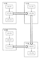
図1は、本発明の実施の形態1に係る停止原因特定支援装置が適用されたシステムの構築例を示す図である。このシステムは、それぞれ1つ以上の生産ラインが設けられた複数の工場3から必要な情報を収集し、1つ以上の工場3を所有する各顧客に対して、有用な情報を提供するサービスを実現させるために構築されている。
FIG. 1 is a diagram showing a construction example of a system to which the stop cause identification support device according to the first embodiment of the present invention is applied. This system collects necessary information from a plurality of
各工場3では、例えば図1に示すように、複数のPLC(Programmable Logic Controller)31、及び情報収集装置32が存在し、それらがネットワーク33に接続されている。各PLC31は、生産ラインの各工程に設置された機器、つまり設備を制御し、製品を生産するための情報処理装置である。情報収集装置32は、各PLC31からロギングデータを収集するために設置された情報処理装置である。ロギングデータは、機器の動作状態を示す情報であり、動作状況情報に相当する。PLC31は、機器の動作開始時、及び動作終了時、その動作内容を示す状態データ、生産対象とする製品を示す製品データ、及び時刻データを含むロギングデータを情報収集装置32に送信する。何らかのエラーが発生した場合、例えばPLC31は、そのエラーの種類を示すエラーコード、エラーの発生、或いは解消を示す発生状況データ、エラーが発生した後の状態データ、製品データ、及び時刻データを含むロギングデータを情報収集装置32に送信する。エラーが解消した場合、PLC31は、そのエラーの種類を示すエラーコード、発生状況データ、エラーが解消した後の状態データ、製品データ、及び時刻データを含むロギングデータを情報収集装置32に送信する。なお、PLC31に送信させるロギングデータの内容は、特に限定されない。 In each
図2は、1生産ラインに含まれる工程、及び工程間の順序関係の例を説明する図である。ここで図2、更には図3を参照し、1生産ラインに存在する工程の例について具体的に説明する。 FIG. 2 is a diagram illustrating an example of a process included in one production line and an order relationship between the processes. Here, with reference to FIGS. 2 and 3, an example of a process existing in one production line will be specifically described.
この生産ラインでは、図2に示すように、A〜D工程が存在する。A工程は、サブ工程として、ステップ1〜3の3ステップを含む。B工程は、サブ工程として、ステップ1〜3の3ステップを含む。C工程は、サブ工程として、ステップ1、2の2ステップを含む。D工程は、サブ工程として、ステップ1、2の2ステップを含む。A〜D工程にそれぞれ含まれるサブ工程である各ステップは、全て本実施の形態における工程に相当する。各ステップの作業は、設置された1つ以上の機器により行われる。 In this production line, as shown in FIG. 2, there are steps A to D. Step A includes three
生産ラインには、材料等の物を搬送するための搬送装置が複数、存在する。ここでは、説明上、便宜的に、この搬送装置の存在は無視することとする。つまり機器は、作業に直接的に係わるもののみを想定する。 In the production line, there are a plurality of transport devices for transporting materials and the like. Here, for convenience of explanation, the existence of this transfer device will be ignored. In other words, the equipment is assumed to be only those that are directly related to the work.
各ステップでは、定められた作業が行われる。図2に示す各太矢印は、工程間での物の移動、つまり搬送の流れを表している。例えばA工程のステップ2とC工程のステップ2との間に配置された太矢印は、A工程のステップ2の作業が行われた物が、C工程のステップ2の作業に用いられることを示している。各工程のステップ間に配置された矢印は、ステップが実行される流れを示している。例えばA工程のステップ1とステップ2との間に配置された矢印は、ステップ1の作業が開始した後、ステップ2の作業が開始することを示している。多くの場合、その矢印は、物の移動を共に示している。 At each step, a defined task is performed. Each thick arrow shown in FIG. 2 represents the movement of an object between processes, that is, the flow of transportation. For example, a thick arrow arranged between
工程間で搬送される物は、生産する製品、生産のための生産ラインによって異なる。このことから、ここでは、便宜的に、特に断らない限り、製品は最終的に生産される物のみを指す意味で用いる。他の物は、全て「生成物」と表記する。この生成物は、具体的には、例えば製品、製品に使用される部品、或いは製品の生産に用いる材料である。 The goods transported between processes differ depending on the product to be produced and the production line for production. For this reason, for convenience, unless otherwise specified, a product is used here to mean only the final product. All other things are referred to as "products". The product is specifically, for example, a product, a part used in the product, or a material used in the production of the product.
図3は、図2に表すサブ工程を含む各工程の動作シーケンスの例を示す図である。図3では、横軸に時間をとり、縦軸に各工程を並べて示している。各工程で動作している期間は、網掛けして示している。 FIG. 3 is a diagram showing an example of an operation sequence of each process including the sub-process shown in FIG. In FIG. 3, time is taken on the horizontal axis, and each process is shown side by side on the vertical axis. The period of operation in each process is shaded.
図3に示すように、A工程では、ステップ1の作業終了後、ステップ2の作業が開始し、ステップ2の作業終了後、ステップ3の作業が開始する。各所要時間、つまり各ステップでの機器の動作時間は、ステップ1は2分10秒、ステップ2は40秒、ステップ3は1分10秒である。複数の機器が1ステップ用に設置されている場合、動作時間は、最初に動作する機器が動作を開始してから、全ての機器の動作が終了するまでの時間である。 As shown in FIG. 3, in step A, the work of
B工程は、作業がA工程の作業と並行して行われる工程である。B工程もA工程と同様に、ステップ1の作業終了後、ステップ2の作業が開始し、ステップ2の作業終了後、ステップ3の作業が開始する。各所要時間、つまり各ステップでの機器の動作時間は、ステップ1は1分10秒、ステップ2は1分40秒、ステップ3は1分20秒である。A、B工程のステップ1の作業開始タイミング、つまり機器の動作開始タイミングは、同じタイミングで設定しても良く、異ならせても良い。図3に示す例では、同じタイミングとなっている。 Step B is a step in which the work is performed in parallel with the work of step A. In step B, similarly to step A, the work in
C工程は、作業がA工程の作業と並行して行われる工程である。C工程も、ステップ1の作業終了後、ステップ2の作業が開始する。各所要時間は、ステップ1は1分、ステップ2は20秒である。ステップ1の作業開始タイミング、つまり機器の動作開始タイミングは、A工程のステップ2の作業開始から20秒後である。 Step C is a step in which the work is performed in parallel with the work of step A. In step C, the work of
D工程も、ステップ1の作業終了後、ステップ2の作業が開始する。各所要時間は、ステップ1は50秒、ステップ2は40秒である。ステップ1の作業開始タイミング、つまりステップ1の機器の動作開始タイミングは、B工程のステップ3の作業終了タイミングである。 In step D, the work of
図1の説明に戻る。各工場3に設置された情報収集装置32は、図1に示すように、ネットワーク2と接続されている。このネットワーク2には、サービス提供用の情報処理装置であるサーバ1が接続されている。各情報収集装置32が各PLC31から収集したロギングデータは、ネットワーク2を介してサーバ1に送信される。 Returning to the description of FIG. As shown in FIG. 1, the
サーバ1は、機能構成として、図1に示すように、通信部11、通信制御部12、収集制御部13、及び停止原因特定支援装置14を含む。サーバ1上に実現された停止原因特定支援装置14は、本実施の形態に係る停止原因特定支援装置である。 As a functional configuration, the
通信部11は、ネットワーク2を介した通信を実現させるハードウェア資源である。通信制御部12は、通信部11を制御し、ネットワーク2を介したデータの送受信を通信部11に行わせる。収集制御部13は、通信制御部12を制御して、各情報収集装置32からロギングデータを収集する。 The
停止原因特定支援装置14は、機能構成として、図1に示すように、記憶部141、データ生成部142、停止工程検出部143、影響工程特定部144、影響時間算出部145、結果保存部146、及び出力制御部147を含む。 As shown in FIG. 1, the stop cause
記憶部141は、各種データの記憶に用いられる1つ以上のハードウェア資源である。より具体的には、記憶部141は、例えばハードディスク装置、SSD(Solid State Drive)、及びRAM(Random Access Memory)のうちの一つ以上を含むハードウェア資源である。収集制御部13の通信制御部12への制御により、通信部11が各情報収集装置32から受信するロギングデータは、工場3別、生産ライン別にまとめられたロギングデータ群1411として、通信制御部12を介して記憶部141に記憶される。 The
記憶部141には、複数のロギングデータ群1411の他に、工程管理データ1412、エラー状況データ1413、及び停止関連データ1414が記憶される。これら各種データについて、図4〜図8にそれぞれ示す説明図を参照して具体的に説明する。 In addition to the plurality of
図4は、工程管理データの構成例を説明する図である。この工程管理データ1412は、生産ラインに含まれる各工程の工程データがまとめられたデータである。各工程データは、対応する工程に係わるデータである。各行に表記した内容は、工程データの具体的な内容を示している。このことから、図4に示すように、各工程データには、工程ID(IDentifier)、動作時間、開始タイミング、開始条件、前工程、後工程、搬送先、機器IDの各データが含まれている。なお、図4に示す工程データの構成は、1例であり、工程データはこの構成に限定されない。 FIG. 4 is a diagram illustrating a configuration example of process control data. The
工程IDデータは、自工程に割り当てられた識別情報である。図4中に表記の「A ステップ1」は、自工程がA工程のステップ1であることを示している。動作時間データは、作業の所要時間、言い換えれば自工程用に設置された機器の基準となる動作時間を示すデータである。工程IDデータとして「A ステップ1」が表記された行に動作時間データとして表記の130秒は、A工程のステップ1用に設置された機器が動作を開始してから終了するまでの動作時間が130秒であることを示している。 The process ID data is identification information assigned to the own process. “A
開始タイミングデータは、機器が動作を開始するタイミングを示すデータである。工程IDデータとして「A ステップ2」が表記された行に開始タイミングデータとして表記の「A ステップ1終了」は、A工程のステップ1の終了により、A工程のステップ2が開始することを示している。また、工程IDデータとして「A ステップ1」が表記された行に開始タイミングデータとして表記の「NULL」は、他の工程に影響されずに任意のタイミングで開始されることを示している。 The start timing data is data indicating the timing at which the device starts operating. "A
開始条件データは、自工程の作業を開始、言い換えれば機器の動作を開始させることが可能となる条件を示すデータである。工程IDデータとして「A ステップ1」が表記された行に開始条件データとして表記の「D ステップ2終了」は、D工程のステップ2が終了することにより、A工程のステップ1が開始可能になることを示している。ここでのD工程のステップ2の終了には、生産ラインでの製品の生産を開始する前の状況も含まれる。A工程のステップ1は、D工程のステップ2が終了している状況であることを条件に、任意のタイミングで作業を開始させることができる。 The start condition data is data indicating a condition that enables the work of the own process to be started, in other words, the operation of the device to be started. For "
前工程データは、自工程の直前に位置する工程を示す識別情報である。後工程データは、自工程の直後に位置する工程を示す識別情報である。図2に示すように、A工程のステップ1、B工程のステップ1、及びC工程のステップ1には、前工程が存在しない。そのため、それら前工程データとして全て「NULL」が表記されている。 The pre-process data is identification information indicating a process located immediately before the own process. The post-process data is identification information indicating a process located immediately after the own process. As shown in FIG. 2, there is no previous step in
搬送先データは、生産物の搬送先となる工程を示す識別情報である。A工程のステップ1では、生産物がA工程のステップ2に搬送されることから、搬送先データとして「A ステップ2」が表記されている。 The destination data is identification information indicating a process to be the destination of the product. In
機器IDデータは、自工程の作業用に設置された機器を示す識別情報である。生産物に係わる作業を機器により行う工程では、1つ以上の機器が設置される。そのため、機器毎に、その機器を示す識別情報が機器IDデータとして保存される。機器IDデータは、機器を管理するデータの一例を示すものである。 The device ID data is identification information indicating the device installed for the work of the own process. One or more devices are installed in the process of performing the work related to the product by the devices. Therefore, for each device, identification information indicating the device is stored as device ID data. The device ID data shows an example of data for managing the device.
工程管理データ1412には、このような工程データが工程別に存在する。そのため、停止原因特定支援装置14は、工程別に、動作開始の遅延、動作を開始した後に発生した停止、等をロギングデータから確認することができる。 In the
本実施の形態では、他の工程を原因として、動作開始後に停止する途中停止が発生した工程が発生した場合、その停止を発生させる根本的な原因が発生した工程、及びその工程の下流側で途中停止が発生した最後の工程を特定する。以降、便宜的に、根本的な原因が発生した工程は「影響工程」、最後の工程は「最終停止工程」とそれぞれ表記する。ここでの根本的な原因とは、自工程のみに起因する原因のことである。言い換えれば、根本的な原因は、工程間に影響が伝搬する最初の停止を発生させた停止原因となるエラーのことである。本実施の形態において、影響工程は第1の停止工程に相当し、最終停止工程は第2の停止工程に相当する。 In the present embodiment, when a process in which a stop is generated after the start of operation occurs due to another process, the process in which the root cause of the stop occurs and the downstream side of the process Identify the last step in which the stop occurred. Hereinafter, for convenience, the process in which the root cause has occurred will be referred to as an "influenced process", and the final process will be referred to as a "final stop process". The root cause here is a cause caused only by the own process. In other words, the root cause is the error that caused the stop that caused the first stop to propagate the effect between processes. In the present embodiment, the influencing step corresponds to the first stop step and the final stop step corresponds to the second stop step.
影響工程が何らかの原因により停止した場合、その停止により、生産物が搬送されるタイミングが遅くなる。結果、影響工程より下流側の各工程では、停止が発生しなかった場合と比較し、少なくとも動作が終了するタイミングは遅くなる。前工程の動作終了により次の工程の動作が開始されるような工程群では、停止した工程の下流側の各工程は、停止時間だけ、動作開始、及び動作終了が遅くなる。動作開始が遅延した工程は、その工程が停止したと見ることができる(例えば、特許文献1)。 If the affected process is stopped for some reason, the stop delays the timing at which the product is transported. As a result, in each process downstream from the affected process, at least the timing at which the operation ends is delayed as compared with the case where the stop does not occur. In a process group in which the operation of the next process is started by the end of the operation of the previous process, each process on the downstream side of the stopped process is delayed in starting and ending the operation by the stop time. A process in which the start of operation is delayed can be regarded as having stopped the process (for example, Patent Document 1).
一方、影響工程の停止により、途中停止が発生した工程では、途中停止した時間である途中停止時間が影響工程の停止時間と一致するとは限らない。影響工程で発生した停止が他の工程に及ぼす影響の度合いは、他の工程で行われる作業の内容、生産する生産物、等によって変化する場合がある。このことから、本実施の形態では、最終停止工程で発生した途中停止時間のうち、影響工程の停止時間が及ぼしたと推定される影響分を影響時間として特定し、サービスの提供対象者に提示可能にしている。この提供対象者は、通常、利用者側が定めた担当者である。このことから、提供対象者は、以降「担当者」と表記する。 On the other hand, in a process in which a halfway stop occurs due to the stoppage of the affected process, the halfway stop time, which is the halfway stop time, does not always match the stop time of the affected process. The degree of influence of the stoppage generated in the affected process on the other process may vary depending on the content of the work performed in the other process, the product to be produced, and the like. From this, in the present embodiment, among the intermediate stop times generated in the final stop process, the influence portion estimated to have been exerted by the stop time of the influence process can be specified as the influence time and presented to the service provider. I have to. The person to be provided is usually the person in charge designated by the user. For this reason, the person to be provided will be referred to as the "person in charge" hereafter.
特定した影響時間は、停止による製品の生産量の低下をより抑えるための対策等を講じるための有用な情報となる。そのような情報の提供により、工場3の所有者にとっては、より望ましい生産ラインの構築、或いは改良をより容易に行えるようになる。従って、所有者にとっては、工程に発生する停止を想定しつつ、より大量の製品を生産可能な生産ラインをより容易に実現させられるように支援されることになる。 The identified impact time will be useful information for taking measures to further suppress the decrease in product production due to the suspension. By providing such information, it becomes easier for the owner of the
図5は、発生したエラーの各工程への影響例を示す図である。この影響例は、図3に示すような動作シーケンスでサブ工程を含む各工程が動作する場合を想定したものである。ここで、図5を参照し、工程を停止させるエラーの発生時、その停止が他の工程に及ぼす影響について具体的に説明する。 FIG. 5 is a diagram showing an example of the influence of the generated error on each process. This example of influence assumes a case where each process including a sub-process operates in an operation sequence as shown in FIG. Here, with reference to FIG. 5, when an error that stops a process occurs, the influence of the stop on other processes will be specifically described.
図5でも図3と同様に、横軸に時間をとり、縦軸に各工程を並べて示している。各工程で動作している期間、より正確には、各工程で動作を開始してから動作が終了するまでの期間は、網掛けして示し、その期間中の停止期間は、太枠で示している。各太枠内に表記のa〜fは、それぞれ発生したエラーを示している。図5に示すエラーは、表記のシンボルを最後に付加して表すこととする。それにより、例えば「a」が表記されたエラーは、「エラーa」と表記する。これは、後述する図6でも同じである。 In FIG. 5, as in FIG. 3, time is taken on the horizontal axis, and each process is shown side by side on the vertical axis. The period during which each process is operating, or more accurately, the period from the start of operation to the end of operation in each process, is shaded, and the stop period during that period is indicated by a thick frame. ing. The a to f shown in each thick frame indicate the error that occurred. The error shown in FIG. 5 is represented by adding the notation symbol at the end. As a result, for example, an error in which "a" is described is described as "error a". This also applies to FIG. 6 described later.
図5に示す例では、A工程のステップ2が動作開始してから20秒後、エラーaが発生して3分10秒間、動作が停止し、そのエラーaが解消した後、直ちにエラーbが発生して、更に1分10秒間、動作が停止している状態が継続している。C工程では、ステップ1が動作開始してから40秒後、エラーcが発生して30秒間、動作が停止している。これらエラーa〜c、及びD工程のステップ2の動作を30秒間、停止させたエラーfは、全て自工程のみに起因する原因となるエラーである。 In the example shown in FIG. 5, 20 seconds after the operation of
C工程のステップ1は、図4に示すように、A工程のステップ1が動作開始してから20秒後に動作を開始する。C工程のステップ2は、C工程のステップ1の動作終了後に動作を開始する。このことから、C工程のステップ2は、図5に示すように、C工程のステップ1で発生したエラーcにより、通常よりも30秒だけ遅れて動作を開始している。 As shown in FIG. 4,
C工程のステップ2には、図2、及び図4に示すように、A工程のステップ2の作業により得られた生成物が搬送される。しかし、A工程のステップ2には、エラーa、及びbにより、計4分20秒の停止時間が発生する。このため、C工程のステップ2では、動作開始してから10秒後、生成物が搬送されないことによってエラーdが発生し、4分20秒間の途中停止時間が発生する。D工程のステップ1も同様に、B工程のステップ3の動作終了によって動作を開始してから10秒後、C工程のステップ2からの生成物が搬送されないことによってエラーeが発生し、4分10秒間の途中停止時間が発生する。 As shown in FIGS. 2 and 4, the product obtained by the operation of
図5に示す例では、A工程のステップ2での停止の影響がC工程のステップ2を介し、D工程のステップ1に伝搬している。このことから、A工程のステップ2が影響工程となり、D工程のステップ1が最終停止工程となっている。なお、図5に示す例では、影響工程は1つとなっているが、影響工程は複数の場合もある。例えば、C工程のステップ1において、エラーcの他に、自工程のみに起因するエラーが発生した場合、C工程のステップ1も影響工程となる。 In the example shown in FIG. 5, the effect of the stop in
図5に示す例では、最終停止工程であるD工程のステップ1での途中停止時間は4分10秒であり、影響工程であるA工程のステップ2での停止時間は4分20秒である。このことから、影響工程の停止時間と、最終停止工程の途中停止時間との間の差は比較的に小さい。しかし、生産物、作業内容、動作する機器等により、それらの間の差が比較的に大きい場合もある。そのため、影響工程の停止が最終停止工程の途中停止に及ぼすと推定される影響分、つまり影響時間を特定することは、停止の影響が伝搬する度合いを確認するうえで有用である。 In the example shown in FIG. 5, the stop time in
本実施の形態では、下流側から、途中停止が発生した工程を検出し、検出した工程が最終停止工程に相当するか否かを確認するようにしている。図1に示す停止工程検出部143は、途中停止が発生した工程を検出する構成要素である。影響工程特定部144は、停止工程検出部143が検出した工程を基点とし、基点とする工程から上流側に工程を辿り、影響工程を特定する構成要素である。影響工程が特定できた場合、基点とする工程は最終停止工程と位置付けられる。本実施の形態において、停止工程検出部143、及び影響工程特定部144は共に工程特定部に相当する。 In the present embodiment, the process in which the intermediate stop occurs is detected from the downstream side, and it is confirmed whether or not the detected process corresponds to the final stop process. The stop
本実施の形態では、上記のように、影響工程、及び最終停止工程の特定は、最初に最終停止工程の候補を検出して行うようになっている。しかし、これは1例である。つまり、最初に影響工程の候補を検出するようにしても良い。或いは、停止した任意の工程を選択し、上流側に存在する影響工程の有無、及び下流側に存在する最終停止工程の有無をそれぞれ確認するようにしても良い。 In the present embodiment, as described above, the influence step and the final stop step are specified by first detecting the candidate of the final stop step. However, this is just one example. That is, the candidate of the influential process may be detected first. Alternatively, an arbitrary stopped process may be selected, and the presence or absence of an influential process existing on the upstream side and the presence or absence of a final stop process existing on the downstream side may be confirmed.
影響時間算出部145は、影響工程で発生した自工程のみに起因するエラー毎に、そのエラーによる停止が最終停止工程に及ぼしたと推定される時間を影響時間として算出する構成要素である。本実施の形態では、影響時間の算出は、発生した時刻が遅い方のエラーを優先し、そのエラーによる停止時間を上限に、最終停止工程の途中停止時間、或いはその一部を割り当てる形で行うようにしている。そのため、影響時間の合計は、最終停止工程の途中停止時間を越えることはない。つまり、影響時間の合計の最大は、最終停止工程の途中停止時間となる。本実施の形態において、影響時間算出部145は時間算出部に相当する。 The influence
本実施の形態では、影響時間の算出に発生した時刻が遅い方のエラーを優先させている。これは、最終停止工程の動作再開タイミングへの影響は、時間が遅い方のエラーほど大きいためである。また、時間的に早く発生したエラーが、他のエラーを発生させる可能性もある。このようなことから、時間的に遅く発生したエラーへの対策がより重要となるケースの割合がより高いと考えられる。そのため、影響時間の算出に発生した時刻が遅い方のエラーを優先させつつ、エラー別に影響時間を算出することは、対策の重要性がより高いエラーを担当者により強く認識させるうえで有効である。 In the present embodiment, priority is given to the error that occurs later in the calculation of the influence time. This is because the effect on the operation restart timing of the final stop process is greater for the error with the later time. Also, an error that occurs earlier in time may cause another error. For this reason, it is considered that the percentage of cases in which countermeasures against errors that occur late in time are more important is higher. Therefore, it is effective to calculate the impact time for each error while giving priority to the error that occurred later in the calculation of the impact time in order to make the person in charge more aware of the error for which the countermeasure is more important. ..
図6は、影響時間の算出方法例を説明する図である。ここで図6を参照し、本実施の形態で採用した影響時間の算出方法の例について具体的に説明する。上記のように、この図6に示す例は、図5に示す例を前提としたものである。 FIG. 6 is a diagram illustrating an example of a method for calculating the influence time. Here, with reference to FIG. 6, an example of the method of calculating the influence time adopted in the present embodiment will be specifically described. As described above, the example shown in FIG. 6 is premised on the example shown in FIG.
図5に示す例では、上記のように、影響工程であるA工程のステップ2の停止の影響は、C工程のステップ2を介し、最終停止工程であるD工程のステップ1に伝搬している。そのため、影響時間は、D工程のステップ1、及びC工程のステップ2ともに0秒となる。A工程のステップ2では、エラーa、bの2つのエラーが発生していることから、時間的に遅く発生したエラーbでは、影響時間は停止時間と同じ1分10秒と算出される。 In the example shown in FIG. 5, as described above, the influence of the stoppage of
エラーbの影響時間を1分10秒とすることにより、影響時間として算出可能な時間の上限は3分(=4分10秒−1分10秒)となる。エラーaによる停止時間は、3分10秒である。このため、エラーaの影響時間は、3分となる。 By setting the influence time of error b to 1 minute and 10 seconds, the upper limit of the time that can be calculated as the influence time is 3 minutes (= 4
図5、及び図6に示す例では、最終停止工程の途中停止時間と、影響工程の停止時間との間の関係は、最終停止工程の途中停止時間<影響工程の停止時間、の関係となっている。しかし、この大小関係が逆となる場合もある。この場合は、影響工程の停止の影響がより大きく最終停止工程に及ぼしたことを意味する。そのため、この場合には、影響工程での停止が発生しないようにすることがより重要となる。 In the examples shown in FIGS. 5 and 6, the relationship between the stop time of the final stop process and the stop time of the affected process is the relationship of the stop time of the final stop process <the stop time of the affected process. ing. However, this magnitude relationship may be reversed. In this case, it means that the influence of the stop of the influential process was greater and had an effect on the final stop process. Therefore, in this case, it is more important to prevent the stoppage in the influencing process from occurring.
図5、及び図6に示すように、影響工程の停止が影響する他の工程では、その停止によるエラーが発生する。また、途中停止が発生する工程では、PLC31は、動作の停止時、及び動作の再開時にロギングデータを生成する。そのため、影響工程、及び最終停止工程の特定、並びに影響時間の算出のためにロギングデータ群1411のうちで実際に参照すべきロギングデータは全体の一部である。参照すべきロギングデータは分散している。このことから、本実施の形態では、処理の負荷を軽減させるために、エラー状況データ1413を生成するようにしている。図1に示すデータ生成部142は、ロギングデータ群1411を参照し、エラー状況データ1413を生成する構成要素である。 As shown in FIGS. 5 and 6, in other steps affected by the stoppage of the affected step, an error occurs due to the stoppage. Further, in the process in which the intermediate stop occurs, the
図7は、エラー状況データの構成例を説明する図である。ここで図7を参照し、エラー状況データ1413の構成例について具体的に説明する。図7に構成例を示す各エラー状況データ1413は、図5、及び図6に示すエラーa〜fが発生した場合を想定したものである。 FIG. 7 is a diagram illustrating a configuration example of error status data. Here, a configuration example of the
エラー状況データ1413は、工程別に生成されるデータである。エラー状況データ1413は、エラーの発生時、そのエラーの解消時の状況、更には工程間に伝搬するエラーの影響の有無を確認可能にする。そのために、エラー状況データ1413は、図7に示すように、停止工程、停止日時、再開日時、停止時間、発生エラー、発生製品の各データを含む構成となっている。 The
停止工程データは、停止が発生した工程を示すデータである。この停止工程データが示す工程は、最終停止工程、及び影響工程のうちの何れかの候補となる可能性がある。停止日時データは、停止工程データが示す工程が停止した日時を示すデータである。再開日時データは、停止工程データが示す工程の動作が再開した日時を示すデータである。停止時間データは、停止工程データが示す工程が停止していた時間を示すデータである。 The stop process data is data indicating a process in which a stop has occurred. The process indicated by the stop process data may be a candidate for either the final stop process or the influential process. The stop date / time data is data indicating the date and time when the process indicated by the stop process data is stopped. The restart date / time data is data indicating the date and time when the operation of the process indicated by the stop process data is restarted. The stop time data is data indicating the time during which the process indicated by the stop process data was stopped.
発生エラーデータは、停止工程データが示す工程で発生したエラーを示すデータである。図5、及び図6に示すように、1つの工程で複数のエラーが発生する場合がある。このことから、発生エラーデータには、エラー毎に、つまり停止を発生させた原因毎に、そのエラーの発生状況を示すエラーデータが存在する。 The occurrence error data is data indicating an error generated in the process indicated by the stop process data. As shown in FIGS. 5 and 6, a plurality of errors may occur in one process. For this reason, the occurrence error data includes error data indicating the occurrence status of the error for each error, that is, for each cause that caused the stop.
エラーデータは、図7に示すように、エラーコード、発生日時、及び解消日時の各データを含む。エラーコードデータは、発生したエラーの種類を示すデータである。発生日時データは、エラーが発生した日時を示すデータである。解消日時データは、エラーが解消した日時を示すデータである。 As shown in FIG. 7, the error data includes each data of the error code, the date and time of occurrence, and the date and time of resolution. The error code data is data indicating the type of error that has occurred. The occurrence date and time data is data indicating the date and time when the error occurred. The resolution date / time data is data indicating the date and time when the error was resolved.
発生製品データは、エラーが発生した製品を示すデータである。発生製品データには、発生ロットデータ、及び通番データが含まれる。ロットは、製品を生産する最小単位である。発生ロットデータは、エラーが発生した製品に割り当てられたロットを示すデータである。通番データは、エラーが発生した製品をロット内で特定可能にするデータである。通番データとして表記の「9/10」は、製品の総数が10のロットで9番目に生産される製品であることを表している。製品毎に識別情報が割り当てられる場合、発生製品データは、その識別情報としても良い。 The generated product data is data indicating the product in which the error occurred. The generated product data includes the generated lot data and the serial number data. A lot is the smallest unit that produces a product. The generated lot data is data indicating the lot assigned to the product in which the error occurred. The serial number data is data that makes it possible to identify the product in which the error has occurred within the lot. "9/10" shown as serial number data indicates that the total number of products is the ninth product produced in a lot of 10. When identification information is assigned to each product, the generated product data may be used as the identification information.
工程間に伝搬する停止の影響は、同じ製品の生産時を前提として確認する必要がある。本実施の形態では、工程間に伝搬する影響の確認を製品毎に、より容易、且つより確実に行えるように、発生製品データをエラー状況データに含めている。しかし、発生製品データは、エラー状況データに含めなくとも良い。これは、停止日時データ等の他のデータ、及び工程管理データ1412により、発生製品データがなくとも工程間に伝搬する影響の確認を製品毎に行うことが可能だからである。 The effect of suspension propagating between processes needs to be confirmed on the assumption that the same product will be produced. In the present embodiment, the generated product data is included in the error status data so that the influence propagating between the processes can be confirmed for each product more easily and more reliably. However, the generated product data does not have to be included in the error status data. This is because it is possible to confirm the influence of propagating between processes for each product by using other data such as stop date / time data and
図1に示すデータ生成部142は、例えば新たに記憶部141に記憶されたロギングデータ群1411を参照して、工場別、生産ライン別に、エラー状況データ1413の生成を行う。停止工程検出部143、影響工程特定部144、及び影響時間算出部145は、記憶部141に記憶されたエラー状況データ1413を参照して処理を行う。 The
図1に示す結果保存部146は、影響工程、及び最終停止工程の各特定結果を示す停止関連データ1414を生成して記憶部141に保存する構成要素である。出力制御部147は、オペレータからの指示、或いは予め定められた設定に従い、各種情報の出力を行う構成要素である。 The
図14は、出力制御部によって出力される情報の例を説明する図である。図14に示す例は、指定された期間内に、各工程で発生した停止時間の合計を工程別に示すグラフである。 FIG. 14 is a diagram illustrating an example of information output by the output control unit. The example shown in FIG. 14 is a graph showing the total stop time generated in each process within a designated period for each process.
各工程で発生した停止時間の合計は、指定された期間内に停止したことを示す停止日時データが含まれるエラー状況データ1413を抽出することで行うことができる。抽出したエラー状況データ1413を停止工程データにより分け、停止時間データが示す停止時間を加算することにより、工程別に停止時間の合計を求めることができる。図14に示す例では、停止時間の合計の大きさにより、グラフ上での工程の配置が決定されている。 The total stop time generated in each step can be performed by extracting the
図8は、停止関連データの構成例を説明する図である。ここで図8を参照し、結果保存部146によって生成される停止関連データについて具体的に説明する。 FIG. 8 is a diagram illustrating a configuration example of stop-related data. Here, with reference to FIG. 8, the stop-related data generated by the
停止関連データは、図8に示すように、発生製品データ、最終停止工程データ、及び生産系統データを含む。 As shown in FIG. 8, the stop-related data includes the generated product data, the final stop process data, and the production system data.
発生製品データは、影響工程、及び最終停止工程が特定された製品を示すデータである。この発生製品データは、参照されたエラー状況データ1413中から抽出されるデータである。 The generated product data is data indicating the product for which the affected process and the final stop process are specified. This generated product data is data extracted from the referenced
最終停止工程データは、特定された最終停止工程に係わるデータである。この最終停止工程データには、図8に示すように、工程ID、停止日時、及び停止時間の各データが含まれる。工程IDデータは、最終停止工程を示すデータである。停止日時データは、最終停止工程が途中停止した日時を示すデータである。停止時間データは、最終停止工程が途中停止していた時間を示すデータである。 The final stop process data is data related to the specified final stop process. As shown in FIG. 8, the final stop process data includes process ID, stop date and time, and stop time data. The process ID data is data indicating a final stop process. The stop date and time data is data indicating the date and time when the final stop process was stopped halfway. The stop time data is data indicating the time during which the final stop process was stopped halfway.
図2、及び図4に示すように、生産ラインには、別の1以上の工程でそれぞれ生産物を生産し、生産された複数の生産物が1つの工程に搬送され、別の生産物、或いは製品を生産するようになっているものも存在する。複数の生産物が搬送される工程では、前工程が複数、存在することになる。そのため、図4に示すように、工程IDデータとして「D ステップ1」が表記された行では、前工程データとして、「B ステップ3、C ステップ2」が表記されている。D工程のステップ1は、本実施の形態における分岐工程に相当する。なお、分岐工程としては、後工程が複数、存在する工程もあり得る。 As shown in FIGS. 2 and 4, each product is produced in one or more different processes on the production line, and the plurality of produced products are transported to one process to obtain another product. Alternatively, there are some that are designed to produce products. In the process of transporting a plurality of products, there are a plurality of pre-processes. Therefore, as shown in FIG. 4, in the line in which "
複数の生産物が搬送される工程では、上流側に工程を辿る場合、その工程で分岐が発生することになる。本実施の形態では、この分岐により分かれる異なる工程の連なりをそれぞれ生産系統とし、生産系統毎に、影響工程を特定するようにしている。それにより、生産系統データには、生産系統毎に、特定された影響工程に係わる影響工程データが存在する。このため、影響工程が特定された場合、1つ以上の生産系統データが停止関連データに存在することになる。 In the process of transporting a plurality of products, when the process is traced to the upstream side, branching occurs in the process. In the present embodiment, a series of different processes divided by this branch is used as a production system, and an influential process is specified for each production system. As a result, the production system data includes the influence process data related to the specified influence process for each production system. Therefore, when the influential process is specified, one or more production system data will be present in the stop-related data.
生産系統の全てに影響工程が存在するとは限らない。そのため、生産系統毎に、影響工程を特定することにより、存在する全ての影響工程を特定することができる。それにより、担当者は、生産系統毎に、影響工程の有無、及び最終停止工程に伝搬した影響工程の停止の影響分を確認することができる。後工程が複数、存在する分岐工程を介して停止の影響が伝搬する場合、複数の生産系統のそれぞれで最終停止工程が特定され、最終停止工程毎に、同じ影響工程で影響分が評価されることとなる。 Not all production systems have influential processes. Therefore, by specifying the influencing process for each production system, all the existing influencing processes can be specified. As a result, the person in charge can confirm the presence or absence of the affected process and the effect of the stop of the affected process propagated to the final stop process for each production system. When the effect of a stop is propagated through a branch process in which there are multiple post-processes, the final stop process is specified in each of the multiple production systems, and the effect is evaluated in the same effect process for each final stop process. It will be.
影響工程データは、特定された影響工程毎に生成されるデータである。この影響工程データには、図8に示すように、工程ID、及びエラーデータが含まれる。 The influence process data is data generated for each specified influence process. As shown in FIG. 8, the influence process data includes the process ID and the error data.
工程IDデータは、特定された影響工程を示すデータである。エラーデータは、特定された影響工程で発生したエラーに係わるデータである。そのため、影響工程データには、1つ以上のエラーデータが含まれる。 The process ID data is data indicating the identified affected process. The error data is data related to the error that occurred in the specified influence process. Therefore, the influence process data includes one or more error data.
エラーデータは、図8に示すように、エラーコード、実停止時間、影響時間の各データを含む。エラーコードデータは、発生したエラーの種類を示すデータである。実停止時間データは、発生したエラーによって停止していた時間を示すデータである。この実停止時間データは、例えばエラー状況データ1413中の停止時間データである。影響時間データは、上記のように、影響時間算出部145によって算出された影響時間を示すデータである。 As shown in FIG. 8, the error data includes each data of the error code, the actual stop time, and the influence time. The error code data is data indicating the type of error that has occurred. The actual stop time data is data indicating the time when the machine was stopped due to an error that occurred. This actual stop time data is, for example, the stop time data in the
なお、停止関連データ1414は、図8に示すような構成に限定されない。例えば最終停止工程以外に停止の影響が伝搬する工程に係わるデータを停止関連データ1414に含めても良い。そのデータを停止関連データ1414に含めることにより、停止関連データ1414を出力するだけで、影響工程に発生した停止の影響が伝搬する他の工程、その工程で発生した影響の程度、等を担当者が確認できるようになる。 The stop-related
停止関連データ1414に加えるデータとしては、例えば影響工程、及び最終停止工程のうちの少なくとも一方の作業内容を示すデータであっても良い。そのデータは、エラーコードデータが示すエラーを発生させる原因の具体例を表すデータであっても良い。エラーを発生させる原因を複数項目に分類し、エラーに対応する項目を示すデータを停止関連データ1414に加えても良い。 The data to be added to the stop-related
原因は、例えば「トラブル」「部材切れ」「人的作業」等の項目に分類することが考えられる。トラブルに分類される原因の具体例としては、部材詰まり、機器の電圧異常、機器の動作異常、等を挙げることができる。部材切れに分類される原因の具体例としては、収納部に収納させておくべき部材が無くなる、作業者が供給すべき部材が供給されない、等を挙げることができる。人的作業に分類される原因の具体例としては、例えば品種、工程内容等を変更する際に生じる段取り作業、治工具の交換作業、調整作業、掃除、等を挙げることができる。停止関連データ1414を構成するデータをより増やすほど、担当者に提供される情報量は増大する。適切な情報をより多く提供するほど、発生したエラーへの対策をより容易に講じられるように担当者を支援できるようになる。原因の各項目とエラーとの間の関係は、例えば項目毎に、対応付けるエラーコードを予め定義しておくことにより、特定させることができる。より詳細、且つ適切な情報提供を実現させる場合、定義は、生産ライン別に行うのが望ましい。 The causes can be classified into items such as "trouble", "out of member", and "human work". Specific examples of the causes classified as troubles include clogging of members, voltage abnormality of equipment, operation abnormality of equipment, and the like. Specific examples of the causes classified as broken members include the absence of members to be stored in the storage unit, the supply of members to be supplied by the operator, and the like. Specific examples of the causes classified as human work include setup work, jig / tool replacement work, adjustment work, cleaning, etc. that occur when changing the product type, process content, and the like. The more data that constitutes the stop-related
図13は、本発明の実施の形態に係る停止原因特定支援装置として用いることが可能な情報処理装置のハードウェア構成例を示す図である。ここで図13を参照し、停止原因特定支援装置14として、つまりサーバ1として用いることが可能な情報処理装置のハードウェア構成例について具体的に説明する。図13では、情報処理装置はサーバ1として用いることが可能なことから、符号として「1」を付している。それにより、情報処理装置は、以降「情報処理装置1」と表記する。 FIG. 13 is a diagram showing a hardware configuration example of an information processing device that can be used as a stop cause identification support device according to the embodiment of the present invention. Here, with reference to FIG. 13, a hardware configuration example of an information processing device that can be used as the stop cause
情報処理装置1は、図13に示すように、ハードウェア構成として、プロセッサ701、メモリ702、NIC(Network Interface Card)703、I/F(InterFace)コントローラ群704、グラフィックコントローラ705を備える。この構成は、1例であり、情報処理装置1の構成は、図13に示すようなものに限定されない。 As shown in FIG. 13, the
メモリ702は、記憶部141に相当する構成要素であり、RAMの他に、ハードディスク装置、SSD等の補助記憶装置が含まれる。このメモリ702には、停止原因特定支援装置14を情報処理装置1上で実現させるプログラムである停止原因特定支援プログラム702aが記憶されている。つまり、この停止原因特定支援プログラム702aをプロセッサ701が実行することにより、情報処理装置1上に停止原因特定支援装置14が実現される。 The
NIC703は、ネットワーク2を介した通信を行う構成要素である。NIC703は、通信部11に相当する。各情報収集装置32からそれぞれネットワーク2上に送信されるロギングデータは、NIC703によって受信され、プロセッサ701の処理により、メモリ702に保存される。そのため、通信制御部12、及び収集制御部13は、プロセッサ701、及びメモリ702を含むハードウェア資源によって実現される。 The NIC703 is a component that performs communication via the
I/Fコントローラ群704を構成する各I/Fコントローラは、情報処理装置1に接続可能な周辺装置との通信を実現させる。周辺装置としては、例えばキーボード、ポインティングデバイス、プリンタ、等を挙げることができる。図13に示す媒体駆動装置710も周辺装置に含まれる。この媒体駆動装置710は、搭載された、或いは着脱可能な記録媒体711にアクセスする装置である。停止原因特定支援プログラム702aは、記録媒体711に記憶させ、媒体駆動装置710から情報処理装置1にロードさせることができる。停止原因特定支援プログラム702aは、ネットワーク2を介して情報処理装置1に送信させるようにしても良い。このようなことから、停止原因特定支援プログラム702aを記録する記録媒体は、メモリ702、及び記録媒体711に限定されない。つまり、記録媒体は、ネットワーク2等を介した通信が可能な他の外部装置がアクセス可能な記録媒体であっても良い。 Each I / F controller constituting the I /
グラフィックコントローラ705は、情報処理装置1と接続された表示装置上に、プロセッサ701に指示された画像データを出力する。そのため、情報処理装置1に表示装置を接続させた場合、担当者は、エラー状況データ1413、停止関連データ1414の各内容を表示装置の画面上から確認することができる。図14に示すようなグラフも表示装置の画面上から確認することができる。表示装置の画面上に出力させる情報は、NIC703、及びネットワーク2を介して、外部装置に送信させても良く、記録媒体711上に保存させても良い。 The graphic controller 705 outputs the image data instructed by the processor 701 on the display device connected to the
図1に示すデータ生成部142、停止工程検出部143、影響工程特定部144、影響時間算出部145、及び結果保存部146は共に、メモリ702上の停止原因特定支援プログラム702aをプロセッサ701が実行することによって実現される。このため、それらは全て、プロセッサ701、及びメモリ702を含むハードウェア資源によって実現される。出力制御部147を実現させるハードウェア資源には、他に、グラフィックコントローラ705、及びI/Fコントローラ群704を構成する1つ以上のI/Fコントローラのうちの少なくとも一つが含まれる。 The processor 701 executes the stop cause
図9及び図10は、停止原因特定処理の例を示すフローチャートである。この停止原因特定処理は、メモリ702に保存されたロギングデータ群1411を参照して、最終停止工程、及び影響工程の特定を行い、その特定結果に応じて、影響時間の算出を行うための処理である。この停止原因特定処理は、上記停止原因特定支援プログラム702aをプロセッサ701が実行することにより実現される。このことから、処理を実行する主体をプロセッサ701とし、停止原因特定処理について詳細に説明する。 9 and 10 are flowcharts showing an example of the stop cause identification process. In this stop cause identification process, the final stop step and the influence process are specified with reference to the
各情報収集装置32が収集したロギングデータは、上記のように、収集制御部13の制御により取得され、記憶部141、言い換えればメモリ702に保存される。このことから、停止原因特定処理は、新たにロギングデータ群1411がメモリ702に保存された後に、自動的に実行させても良い。停止原因特定処理を自動的に実行させる設定は、特に限定されない。また、停止原因特定処理は、オペレータの指示により実行させても良い。その場合、未処理のロギングデータ群1411のみに限定し、停止原因特定処理を実行させても良い。或いはオペレータに期間、工場、或いは生産ラインを指定させ、その指定内容に限定されるロギングデータ群1411のみに制限させて、停止原因特定処理を実行させるようにしても良い。図9及び図10では、説明上、便宜的に、新たにメモリ702に保存されたロギングデータ群1411を対象にしていると想定している。 The logging data collected by each
先ず、ステップS11では、プロセッサ701は、ロギングデータを収集する工場3のうちの1つを対象とする工場3として選択する。次のステップS12では、プロセッサ701は、選択した工場3に設けられた生産ラインのうちの1つを対象とする生産ラインとして選択する。その後に移行するステップS13では、プロセッサ701は、製品毎、及び工程毎に、図7に示すようなエラー状況データ1413を生成する。エラー状況データ1413の生成後はステップS14に移行する。図1に示すデータ生成部142は、ステップS13の処理をプロセッサ701が実行することにより実現される。 First, in step S11, the processor 701 selects one of the
ステップS14では、プロセッサ701は、選択した生産ラインで停止が発生したか否か判定する。生産ラインに含まれる1工程でも停止、言い換えればエラーが発生していた場合、1つ以上のエラー状況データ1413が生成されることになる。そのため、エラー状況データ1413が生成されていた場合、ステップS14の判定はYESとなってステップS15に移行する。エラー状況データ1413が生成されていない場合、ステップS14の判定はNOとなり、図10のステップS34に移行する。 In step S14, processor 701 determines whether or not a stop has occurred on the selected production line. If even one process included in the production line is stopped, in other words, an error has occurred, one or more
ステップS15〜S21では、最終停止工程の候補となりうる工程のエラー状況データ1413を選択し、図8に示す停止関連データ1414の生成に参照の対象となるエラー状況データ1413を抽出し保存するための処理が行われる。 In steps S15 to S21, the
ステップS15では、プロセッサ701は、変数I、Jにそれぞれ1を代入する。変数I、Jは、エラー状況データ1413のなかで他と区別すべきものを抽出して管理・保存するための変数である。変数Iは、生産系統によりエラー状況データ1413を区別するために用いられる。変数Jは、同じ生産系統での工程間の順序関係を特定するために用いられる。そのために、エラー状況データ1413は、例えば変数I、Jの各値と関連付けられて保存される。 In step S15, the processor 701 assigns 1 to each of the variables I and J. The variables I and J are variables for extracting, managing, and storing the
ステップS15に続くステップS16では、プロセッサ701は、工程管理データ1412を参照し、生成されたエラー状況データ1413のうちで最下流工程に位置する工程のエラー状況データ1413を選択して保存する。その保存後は、ステップS17に移行し、プロセッサ701は、選択したエラー状況データ1413が上流の工程で発生した原因、つまりエラーによって生成されたか否か判定する。選択したエラー状況データ1413中の発生エラーデータを構成するエラーデータのうちに、前工程によって発生したエラーを示すエラーコードデータが含まれるエラーデータが存在する場合、ステップS17の判定はYESとなってステップS18に移行する。そのようなエラーコードデータが含まれるエラーデータが発生エラーデータに存在しない場合、ステップS17の判定はNOとなってステップS20に移行する。 In step S16 following step S15, the processor 701 refers to the
本実施の形態では、上記のように、影響工程を除き、その影響工程より下流側の最終停止工程までの間に位置する全ての工程は、最終停止工程を含め、途中停止した工程である。そのため、影響工程を除く他の全ての工程では、前工程での再開日時は、停止日時よりも後となる。この関係に着目し、ステップS17の判定処理を行うようにしても良い。 In the present embodiment, as described above, except for the influential step, all the steps located between the influential step and the final stop step on the downstream side are the steps stopped in the middle including the final stop step. Therefore, in all the steps except the influential step, the restart date and time in the previous step is later than the stop date and time. Focusing on this relationship, the determination process of step S17 may be performed.
ステップS18では、プロセッサ701は、変数Jの値をインクリメントする。続くステップS19では、プロセッサ701は、現在、選択しているエラー状況データ1413の工程の前工程で生成されたエラー状況データ1413を選択して保存する。その保存後は、上記ステップS17に戻る。 In step S18, processor 701 increments the value of variable J. In the following step S19, the processor 701 selects and saves the
ステップS17でのNOの判定は、現在、対象とする生産系統での影響工程の特定が終了したことを意味する。このことから、ステップS17でNOの判定によって移行するステップS20では、ステップS16で選択したエラー状況データ1413に対応する工程の上流側に、影響工程の有無を確認する必要のある生産系統を発生させる分岐があるか否か判定する。ステップS16で選択したエラー状況データ1413に対応する工程は、最終停止工程の候補である。エラーによって停止した工程では、エラー状況データ1413が生成される。このことから、最終停止工程の候補の上流側に位置する工程で生成された未選択のエラー状況データ1413が存在する場合、ステップS20の判定はYESとなってステップS21に移行する。そのようなエラー状況データ1413が残っていない場合、ステップS20の判定はNOとなって図10のステップS31に移行する。 The determination of NO in step S17 means that the identification of the influencing process in the target production system has been completed at present. Therefore, in step S20, which is shifted by determining NO in step S17, a production system for which it is necessary to confirm the presence or absence of an influential process is generated on the upstream side of the process corresponding to the
ステップS21では、プロセッサ701は、変数Iの値をインクリメントし、変数Jに1を代入する。その後に移行するステップS19では、プロセッサ701は、確認された分岐が存在する工程の前工程で生成されたエラー状況データ1413を選択して保存する。選択の対象となるエラー状況データ1413は、未選択のもののみである。 In step S21, the processor 701 increments the value of the variable I and assigns 1 to the variable J. In step S19, which is followed by the transition, the processor 701 selects and stores the
ステップS15〜S21の一連の処理を実行することにより、ステップS16で選択されたエラー状況データ1413に対応する工程が最終停止工程であった場合、そのエラー状況データ1413の他に1つ以上のエラー状況データが保存される。つまり、保存されるエラー状況データ1413の数は2以上でなければ影響工程は存在しないことになる。しかし、エラー状況データ1413の数が2以上であっても、影響工程が存在しない可能性はある。 When the process corresponding to the
図5に示す例のようなエラーが発生した場合、D工程のステップ1が最終停止工程の候補時に保存されるエラー状況データ1413の数は3、或いは4となる。その数は、確認する生産系統の順序によって変化する。例えば変数Iの値が1の生産系統に、C工程のステップ1が含まれていた場合、エラー状況データ1413の数は3となる。変数Iの値が1の生産系統に、C工程のステップ2、及びA工程のステップ2が含まれていた場合、エラー状況データ1413の数は4となる。なお、ステップS16で想定する工程は、影響工程の候補であっても良い。これは、影響工程の候補を基点とし、下流側に工程を辿ったとしても、最終停止工程を特定できるためである。 When an error as shown in the example shown in FIG. 5 occurs, the number of
図10のステップS31では、プロセッサ701は、2以上のエラー状況データ1413が保存されたか否か判定する。保存されたエラー状況データ1413の数が2以上であった場合、ステップS31の判定はYESとなってステップS32に移行する。保存されたエラー状況データ1413の数が1であった場合、ステップS31の判定はNOとなってステップS33に移行する。 In step S31 of FIG. 10, the processor 701 determines whether or not two or more error status data 1413s have been saved. If the number of the saved
ステップS32では、プロセッサ701は、保存されたエラー状況データ1413を参照して影響時間を算出し、停止関連データ1414を生成するための影響時間算出処理を実行する。その実行後は、ステップS33に移行する。この影響時間算出処理の詳細は後述する。 In step S32, the processor 701 calculates the influence time with reference to the saved
ステップS33では、プロセッサ701は、最終停止工程の候補となる他の停止した工程が存在するか否か判定する。候補となる工程が存在する場合、ステップS33の判定はYESとなり、図9のステップS15に戻る。候補となる工程が存在しない場合、ステップS33の判定はNOとなってステップS34に移行する。 In step S33, the processor 701 determines whether or not there is another stopped process that is a candidate for the final stop process. If there is a candidate step, the determination in step S33 is YES, and the process returns to step S15 in FIG. If there is no candidate step, the determination in step S33 becomes NO and the process proceeds to step S34.
ステップS34では、プロセッサ701は、ステップS11で選択した工場3に、選択対象となる生産工程が存在するか否か判定する。選択対象となる生産ラインが残っている場合、ステップS34の判定はYESとなって図9のステップS12に戻る。それにより、ステップS12で別の生産ラインが選択される。一方、選択対象となる生産ラインが存在しない場合、つまりステップS11で選択した工場3で選択対象となる全ての生産ラインの処理が終了した場合、ステップS34の判定はNOとなってステップS35に移行する。 In step S34, the processor 701 determines whether or not the
ステップS35では、プロセッサ701は、選択対象となる工場3が存在するか否か判定する。ステップS11での選択対象となる工場3が残っている場合、ステップS35の判定はYESとなって図9のステップS11に戻る。それにより、未選択の工場3のうちから1つの工場3がステップS11で選択されることとなる。一方、選択対象となる工場3が存在しない場合、ステップS35の判定はNOとなり、ここで停止原因特定処理が終了する。 In step S35, the processor 701 determines whether or not the
上記停止原因特定処理では、停止関連データ1414の生成・保存を行い、停止関連データ1414の生成結果の出力は行わないようになっている。しかし、停止関連データ1414の内容を含む生成結果の出力を併せて行うようにしても良い。停止原因特定処理で停止関連データ1414の特定結果を出力させないのは、生成した停止関連データ1414は保存することから、担当者は任意のタイミング、任意の形態で停止関連データ1414の内容を確認できるからである。 In the stop cause identification process, the stop-related
図11及び図12は、上記ステップS32で実行される影響時間算出処理の例を示すフローチャートである。次に、図11及び図12を参照し、影響時間算出処理について詳細に説明する。ここでも処理を実行する主体はプロセッサ701とする。影響時間算出部145、及び結果保存部146は、この影響時間算出処理の実行により実現される。 11 and 12 are flowcharts showing an example of the influence time calculation process executed in step S32. Next, the influence time calculation process will be described in detail with reference to FIGS. 11 and 12. Here, too, the main body that executes the process is the processor 701. The influence
先ず、ステップS41では、プロセッサ701は、変数I、Jにそれぞれ1を代入する。上記停止原因特定処理では、変数I、Jの各値は、保存されるエラー状況データ1413に関連付けられる。そのため、遅延時間算出処理内では、変数I、Jは、保存されたエラー状況データ1413のうちで参照すべきエラー状況データ1413を管理するために用いられる。 First, in step S41, the processor 701 assigns 1 to each of the variables I and J. In the stop cause identification process, the values of the variables I and J are associated with the stored
ステップS41に続くステップS42では、変数I、Jの値によって指定されるエラー状況データ1413中の停止時間データが示す停止時間を変数T1、T2にそれぞれ代入する。その後はステップS43に移行する。変数T1、T2に代入される停止時間は、最終停止工程での停止時間である。 In step S42 following step S41, the stop time indicated by the stop time data in the
ステップS43〜S55では、変数Iの値を更新することなく、変数Jの値を順次、インクリメントしながら、変数I、Jの各値で指定されるエラー状況データを参照しての処理が行われる。それにより、ステップS43〜S54の一連の処理は、生産系統毎に実行される。 In steps S43 to S55, processing is performed with reference to the error status data specified by each value of the variables I and J while sequentially incrementing the value of the variable J without updating the value of the variable I. .. As a result, the series of processes of steps S43 to S54 is executed for each production system.
ステップS43では、プロセッサ701は、変数Jの値をインクリメントする。次に移行するステップS44では、プロセッサ701は、変数I、Jの各値で指定されるエラー状況データ1413を選択する。その後に移行するステップS45では、プロセッサ701は、選択したエラー状況データ1413に対応する工程が影響工程か否か判定する。選択したエラー状況データ1413に対応する工程が前工程のエラーにより停止していた場合、ステップS45の判定はNOとなってステップS55に移行する。選択したエラー状況データ1413に対応する工程が影響工程であった場合、つまりその工程が自工程のエラーにより停止していた場合、ステップS45の判定はYESとなってステップS46に移行する。 In step S43, processor 701 increments the value of variable J. In the next transition step S44, the processor 701 selects the
ステップS46では、プロセッサ701は、特定された影響工程に自工程による複数のエラーが発生したか否か判定する。エラー状況データ1413中の発生エラーデータに、自工程により発生したエラーを示すエラーコードデータが含まれるエラーデータが複数、存在する場合、ステップS46の判定はYESとなってステップS47に移行する。そのようなエラーデータが1つのみの場合、ステップS46の判定はNOとなってステップS48に移行する。 In step S46, the processor 701 determines whether or not a plurality of errors due to its own process have occurred in the identified affected process. If the occurrence error data in the
ステップS47では、プロセッサ701は、複数のエラーのうちの1つを選択する。エラーの選択では、上記のように、時間的に遅く発生した方が優先される。続くステップS48では、プロセッサ701は、選択したエラーによる停止時間が、変数T2の値が示す時間未満か否か判定する。その大小関係が成立していた場合、ステップS48の判定はYESとなってステップS49に移行する。その大小関係が成立していない場合、ステップS48の判定はNOとなってステップS50に移行する。 In step S47, processor 701 selects one of the plurality of errors. In error selection, as described above, the one that occurs later in time has priority. In the following step S48, the processor 701 determines whether or not the stop time due to the selected error is less than the time indicated by the value of the variable T2. If the magnitude relationship is established, the determination in step S48 becomes YES, and the process proceeds to step S49. If the magnitude relationship is not established, the determination in step S48 becomes NO, and the process proceeds to step S50.
ステップS49では、プロセッサ701は、対象とするエラーによる影響時間を、そのエラーによって生じた停止時間とする。その後、ステップS51に移行する。他方のステップS50では、プロセッサ701は、対象とするエラーによる影響時間を、変数T2の値が示す時間とする。その後、ステップS51に移行する。 In step S49, the processor 701 sets the time affected by the target error as the downtime caused by the error. After that, the process proceeds to step S51. In the other step S50, the processor 701 sets the time affected by the target error as the time indicated by the value of the variable T2. After that, the process proceeds to step S51.
変数T2の値は、影響時間を決定する度に、決定した影響時間分の値が減算される。そのため、図6に示すように、影響工程に対象となる複数のエラーが存在する場合、時間的に遅く発生したエラーから、そのエラーによる停止時間を上限に、影響時間が決定されていくことになる。 As for the value of the variable T2, the value for the determined influence time is subtracted each time the influence time is determined. Therefore, as shown in FIG. 6, when there are a plurality of target errors in the influence process, the influence time is determined from the error that occurred late in time, up to the stop time due to the error. Become.
ステップS51では、プロセッサ701は、他に対象となるエラーが存在するか否か判定する。対象となるエラーが残っていない場合、ステップS51の判定はNOとなってステップS54に移行する。対象となるエラーが残っている場合、ステップS51の判定はYESとなってステップS52に移行する。 In step S51, the processor 701 determines whether or not there is another target error. If no target error remains, the determination in step S51 becomes NO and the process proceeds to step S54. If the target error remains, the determination in step S51 becomes YES, and the process proceeds to step S52.
ステップS52では、プロセッサ701は、変数T2の値から、直前に決定した影響時間分を減算する。続くステップS53では、プロセッサ701は、変数T2の値が正か否か、つまり変数T2の値が0より大きいか否か判定する。変数T2の値が正であった場合、ステップS53の判定はYESとなってステップS47に移行する。変数T2の値が0以下であった場合、ステップS53の判定はNOとなって図12のステップS61に移行する。上記のように、影響時間の合計は、最終停止工程での停止時間を上限としている。そのため、ステップS53でのNOの判定は、影響時間の合計が上限に達したことを意味する。 In step S52, the processor 701 subtracts the effect time determined immediately before from the value of the variable T2. In the following step S53, the processor 701 determines whether or not the value of the variable T2 is positive, that is, whether or not the value of the variable T2 is greater than 0. If the value of the variable T2 is positive, the determination in step S53 becomes YES, and the process proceeds to step S47. When the value of the variable T2 is 0 or less, the determination in step S53 becomes NO, and the process proceeds to step S61 in FIG. As described above, the total effect time is limited to the stop time in the final stop step. Therefore, the determination of NO in step S53 means that the total influence time has reached the upper limit.
上記ステップS51の判定がNOとなって移行するステップS54では、プロセッサ701は、他のエラー状況データ1413が存在するか否か判定する。他のエラー状況データ1413が存在する場合、ステップS54の判定はYESとなって上記ステップS43に戻る。他のエラー状況データが存在しない場合、ステップS54の判定はNOとなって図12のステップS61に移行する。 In step S54, in which the determination in step S51 becomes NO, the processor 701 determines whether or not other
上記ステップS45では、ステップS44でエラー状況データを選択できなかった場合にもNOと判定される。このとから、ステップS45の判定がNOとなって移行するステップS55では、プロセッサ701は、上記ステップS54と同様に、他のエラー状況データ1413が存在するか否か判定する。他のエラー状況データ1413が存在する場合、ステップS55の判定はYESとなって上記ステップS43に戻る。他のエラー状況データが存在しない場合、ステップS55の判定はNOとなって図12のステップS61に移行する。 In step S45, even if the error status data cannot be selected in step S44, it is determined as NO. From this, in step S55 in which the determination in step S45 becomes NO and the transition is made, the processor 701 determines whether or not other
上記のように、ステップS43〜S55の一連の処理は、生産系統毎に実行される。このため、ステップS54でのYESの判定は、同じ生産系統に別の影響工程が存在することを意味する。それにより、ステップS54でのNOの判定は、同じ生産系統に別の影響工程が存在しないことを意味する。 As described above, the series of processes of steps S43 to S55 is executed for each production system. Therefore, the determination of YES in step S54 means that another influence step exists in the same production system. As a result, the determination of NO in step S54 means that there is no other influencing step in the same production system.
図12のステップS61では、他に確認していない生産系統の分岐が存在するか否か判定する。他に確認していない生産系統に連なる分岐工程が存在する場合、変数Iの値をインクリメントした後の値により指定されるエラー状況データが存在する。このため、そのようなエラー状況データが存在する場合、ステップS61の判定はYESとなってステップS62に移行する。そのようなエラー状況データ1413が存在しない場合、つまり他に確認すべき生産工程が存在しない場合、ステップS61の判定はNOとなってステップS68に移行する。 In step S61 of FIG. 12, it is determined whether or not there is another branch of the production system that has not been confirmed. When there is another branching process connected to the production system that has not been confirmed, there is error status data specified by the value after incrementing the value of the variable I. Therefore, when such error status data exists, the determination in step S61 becomes YES, and the process proceeds to step S62. If such
ステップS62では、プロセッサ701は、変数Iの値をインクリメントし、変数T2に変数T1の値を代入する。続くステップS63では、プロセッサ701は、変数Iの値に対応する生産系統が分岐する工程で生成されたエラー状況データ1413を選択する。その後、ステップS64に移行し、プロセッサ701は、選択したエラー状況データ1413に対応する工程を含む下流側に位置する影響工程の有無を確認する。 In step S62, the processor 701 increments the value of the variable I and assigns the value of the variable T1 to the variable T2. In the following step S63, the processor 701 selects the
ステップS64に続くステップS65では、プロセッサ701は、下流側に影響工程があるか否か判定する。下流側に影響工程が確認できた場合、ステップS65の判定はYESとなってステップS66に移行する。下流側に影響工程が確認できなかった場合、ステップS65の判定はNOとなってステップS67に移行する。 In step S65 following step S64, the processor 701 determines whether or not there is an influential step on the downstream side. If the influencing process can be confirmed on the downstream side, the determination in step S65 is YES, and the process proceeds to step S66. If the affected process cannot be confirmed on the downstream side, the determination in step S65 becomes NO, and the process proceeds to step S67.
ステップS66では、プロセッサ701は、下流側に位置する影響工程で求めた影響時間の合計である総影響時間を算出し、算出した総影響時間分の値を変数T2から減算する。この減算結果は、変数Iの値に対応する生産系統での影響時間の合計の上限である。次に移行するステップS67では、プロセッサ701は、変数Jに1を代入する。その代入後に、図11のステップS44に戻る。分岐工程は、既に確認された工程である。そのため、総影響時間の算出は、既に算出された影響時間を合計することで行われる。 In step S66, the processor 701 calculates the total influence time, which is the total of the influence times obtained in the influence step located on the downstream side, and subtracts the value for the calculated total influence time from the variable T2. This subtraction result is the upper limit of the total influence time in the production system corresponding to the value of the variable I. In the next transition step S67, the processor 701 assigns 1 to the variable J. After the substitution, the process returns to step S44 of FIG. The branching process is an already confirmed process. Therefore, the total impact time is calculated by summing the already calculated impact times.
ステップS68に移行する場合、全ての影響工程が特定され、特定された影響工程で発生した自工程によるエラー毎に、影響時間が求められている。しかし、1つの影響工程も特定されない可能性もある。このことから、ステップS68では、プロセッサ701は、特定された影響工程が存在するか否か判定する。1つ以上の影響工程が特定された場合、ステップS68の判定はYESとなってステップS69に移行する。特定された影響工程が存在しない場合、ステップS68の判定はNOとなり、ここで影響時間算出処理が終了する。 When shifting to step S68, all the influencing processes are specified, and the influencing time is calculated for each error caused by the own process that occurs in the specified influencing process. However, one influential step may not be specified either. From this, in step S68, the processor 701 determines whether or not the identified influencing step exists. When one or more influence steps are specified, the determination in step S68 becomes YES, and the process proceeds to step S69. If the specified influence step does not exist, the determination in step S68 becomes NO, and the influence time calculation process ends here.
ステップS69では、プロセッサ701は、最終停止工程のエラー状況データ1413、各影響工程のエラー状況データ1413、及びエラー毎に求めた影響時間を用いて、図8に示すような停止関連データ1414を生成して保存する。その保存後、影響時間算出処理が終了する。 In step S69, the processor 701 generates stop-related
停止関連データ1414により、最終停止工程に影響を与える影響工程が「A ステップ2」であることが判明し、エラーコードとしてはE0000と、E0001が影響していることがわかる。図示していないが、記憶部141にエラー情報データとして、エラーコードとエラー内容との対応、及びそれらを集計・分析用に分類した停止理由を記憶しておく。記憶されているエラー情報をもとに、停止理由の分類を行い、停止の傾向把握に利用できる。停止理由には「トラブル」「部材補給」「段取り替え」等があり、それぞれ発生しているエラー内容やタイミングにより、あらかじめ定義したルールにより、停止理由を判断・記録する。例えば、E0000が「部材詰まり」であり、E0001が「電圧異常」であると登録されていて、停止時にこれらエラーが発生している際は、「トラブル」であるとルール付けされていたとすると、「A ステップ2」の停止の停止分類は、「トラブル」であると分類づけられ、後日エラーの傾向を分析する際に活用できる。 From the stop-related
上記のように、最終停止工程、及び影響工程は、影響時間算出処理の実行により最終的に特定される。このことから、停止工程検出部143、及び影響工程特定部144は、図9のステップS15〜図10のステップS32の一連の処理を実行することにより実現される。 As described above, the final stop step and the influence step are finally specified by executing the influence time calculation process. From this, the stop
本実施の形態では、影響時間の合計の上限を、最終停止工程での停止時間とし、各影響時間の上限を、エラーによって停止した停止時間としている。影響時間の算出に、このような上限を設けなくとも良い。例えばエラーによって停止した停止時間の合計が最終停止工程の停止時間より小さい場合、各エラーの停止時間の全体に占める割合を計算し、計算した割合に停止時間を乗算して得られる時間を影響時間としても良い。 In the present embodiment, the upper limit of the total influence time is the stop time in the final stop process, and the upper limit of each influence time is the stop time stopped due to an error. It is not necessary to set such an upper limit in the calculation of the influence time. For example, if the total stop time stopped due to an error is smaller than the stop time of the final stop process, the ratio of each error to the total stop time is calculated, and the time obtained by multiplying the calculated ratio by the stop time is the affected time. May be.
これは、最終停止工程で発生した停止時間は、全て影響工程での停止による結果と見做すことができるからである。各エラーによる停止の影響が伝搬する程度を考慮して、そのエラーによる停止時間、或いは計算した割合に乗算する係数を設定し、設定した係数を影響時間の算出に用いても良い。影響時間の算出は、様々な変形が可能である。 This is because the stop time generated in the final stop step can be regarded as the result of the stop in the influential step. In consideration of the degree of propagation of the influence of the stop due to each error, a coefficient to be multiplied by the stop time due to the error or the calculated ratio may be set, and the set coefficient may be used for calculating the influence time. The calculation of the effect time can be modified in various ways.
また、本実施の形態では、工場3に実際に設けられた生産ラインを対象にしている。しかし、対象となる生産ラインは、実際に設けられたものでなくとも良い。シミュレーションの対象として設計された仮想的な生産ラインであっても良い。つまり、停止原因特定支援装置14は、シミュレーションにより生成されるロギングデータを参照して、影響工程、及び最終停止工程を特定し、影響時間を算出するものであっても良い。 Further, in the present embodiment, the production line actually provided in the
本実施の形態では、サーバ1上に実現された停止原因特定支援装置14に全ての処理を実行させている。つまり1台の情報処理装置を停止原因特定支援装置14として動作させている。しかし、複数台の情報処理装置に機能を分散させて、複数台の情報処理装置により停止原因特定支援装置14を実現させるようにしても良い。つまり、本実施の形態における停止原因特定支援装置14、更には本実施の形態における停止原因特定支援方法は、複数台の情報処理装置を用いて実現させても良い。 In the present embodiment, the stop cause
1 サーバ、2 ネットワーク、3 工場、11 通信部、12 通信制御部、13 収集制御部、14 停止原因特定支援装置、31 PLC、32 情報収集装置、141
記憶部、142 データ生成部、143 停止工程検出部(工程特定部)、144 影響工程特定部(工程特定部)、145 影響時間算出部(時間算出部)、146 結果保存部、147 出力制御部、1411 ロギングデータ群(動作状況情報群)、1412
工程管理データ、1413 エラー状況データ、1414 停止関連データ。1 server, 2 networks, 3 factories, 11 communication units, 12 communication control units, 13 collection control units, 14 stop cause identification support devices, 31 PLC, 32 information collection devices, 141
Storage unit, 142 Data generation unit, 143 Stop process detection unit (process identification unit), 144 Impact process identification unit (process identification unit), 145 Impact time calculation unit (time calculation unit), 146 Result storage unit, 147 Output control unit , 1411 Logging data group (operation status information group), 1412
Process control data, 1413 error status data, 1414 stop-related data.
Claims (6)
前記動作状況情報を基に、前記生産ラインに存在する複数の工程のうち、他の工程を原因とせずに、動作開始後に停止した工程である第1の停止工程、及び前記第1の停止工程での停止により、動作開始後に停止した最後の工程である第2の停止工程を特定する工程特定部と、
前記第2の停止工程に対して複数の前記第1の停止工程が特定された場合に、前記第2の停止工程で発生した停止に各第1の停止工程が及ぼしたと推定される時間をそれぞれ影響時間とし、前記影響時間の合計の上限を前記第2の停止工程が停止した時間として、前記影響時間を前記第1の停止工程毎に算出する時間算出部と、
を備える停止原因特定支援装置。 For each process existing in the production line, a storage unit that stores operation status information, which is information indicating the operation status of the equipment installed for the process,
Based on the operation status information, among the plurality of processes existing in the production line, a first stop process, which is a process stopped after the start of operation without causing any other process, and the first stop step. A process specification unit that specifies the second stop process, which is the last process stopped after the start of operation, due to the stop at
When a plurality of the first stop steps are specified for the second stop step, the time estimated to be exerted by each first stop step on the stop generated in the second stop step is set respectively. The time calculation unit that calculates the influence time for each of the first stop steps, with the influence time as the upper limit of the total of the influence times and the time when the second stop step is stopped.
A stop cause identification support device equipped with.
請求項1に記載の停止原因特定支援装置。 When a plurality of causes for stopping the first stop step occur at different timings, the time calculation unit calculates the effect time for each cause.
The stop cause identification support device according to claim 1.
請求項1、または2に記載の停止原因特定支援装置。 The process specifying unit identifies one of the candidate for the first stop process and the candidate for the second stop step, and from the one, the candidate for the first stop step and the candidate for the second stop. The first stop process and the second stop process are specified by tracing the process toward the other of the process candidates and confirming the cause of the occurrence for each of the traced processes.
The stop cause identification support device according to claim 1 or 2.
請求項3に記載の停止原因特定支援装置。 When there is a branching process that is a process in which a plurality of processes to be traced exist among the traced processes, the process specifying unit performs a process toward the other for each process having a different trace destination. Follow and confirm the cause of the occurrence,
The stop cause identification support device according to claim 3.
前記第2の停止工程に対して複数の前記第1の停止工程が特定された場合に、前記第2の停止工程で発生した停止に各第1の停止工程が及ぼしたと推定される時間をそれぞれ影響時間とし、前記影響時間の合計の上限を前記第2の停止工程が停止した時間として、前記影響時間を前記第1の停止工程毎に算出する、
処理を情報処理装置に実行させる停止原因特定支援プログラム。 For each process existing in the production line, referring to the operation status information which is the information indicating the operation status of the equipment installed for the process, the cause is the other process among the plurality of processes existing in the production line. Instead, the first stop step, which is a step stopped after the start of the operation, and the second stop step, which is the last step stopped after the start of the operation, are specified by the stop in the first stop step.
When a plurality of the first stop steps are specified for the second stop step, the time estimated to be exerted by each first stop step on the stop generated in the second stop step is set respectively. The influence time is set as the influence time, the upper limit of the total of the influence times is set as the time when the second stop step is stopped, and the influence time is calculated for each of the first stop steps.
A stop cause identification support program that causes the information processing device to execute processing.
前記第2の停止工程に対して複数の前記第1の停止工程が特定された場合に、前記第2の停止工程で発生した停止に各第1の停止工程が及ぼしたと推定される時間をそれぞれ影響時間とし、前記影響時間の合計の上限を前記第2の停止工程が停止した時間として、前記影響時間を前記第1の停止工程毎に算出する、
情報処理装置を用いた停止原因特定支援方法。 For each process existing in the production line, referring to the operation status information which is the information indicating the operation status of the equipment installed for the process, the cause is the other process among the plurality of processes existing in the production line. Instead, the first stop step, which is a step stopped after the start of the operation, and the second stop step, which is the last step stopped after the start of the operation, are specified by the stop in the first stop step.
When a plurality of the first stop steps are specified for the second stop step, the time estimated to be exerted by each first stop step on the stop generated in the second stop step is set respectively. The influence time is set as the influence time, the upper limit of the total of the influence times is set as the time when the second stop step is stopped, and the influence time is calculated for each of the first stop steps.
A support method for identifying the cause of a stop using an information processing device.
Applications Claiming Priority (1)
| Application Number | Priority Date | Filing Date | Title |
|---|---|---|---|
| PCT/JP2019/043892 WO2021090476A1 (en) | 2019-11-08 | 2019-11-08 | Stop cause specification assistance device, stop cause specification assistance program, and method |
Publications (2)
| Publication Number | Publication Date |
|---|---|
| JP6928182B1 true JP6928182B1 (en) | 2021-09-01 |
| JPWO2021090476A1 JPWO2021090476A1 (en) | 2021-11-25 |
Family
ID=75848255
Family Applications (1)
| Application Number | Title | Priority Date | Filing Date |
|---|---|---|---|
| JP2020535674A Active JP6928182B1 (en) | 2019-11-08 | 2019-11-08 | Stop cause identification support device, stop cause identification support program and method |
Country Status (2)
| Country | Link |
|---|---|
| JP (1) | JP6928182B1 (en) |
| WO (1) | WO2021090476A1 (en) |
Families Citing this family (1)
| Publication number | Priority date | Publication date | Assignee | Title |
|---|---|---|---|---|
| JP2021196867A (en) * | 2020-06-15 | 2021-12-27 | 三菱重工機械システム株式会社 | Operation management system of production line, and production line |
Citations (3)
| Publication number | Priority date | Publication date | Assignee | Title |
|---|---|---|---|---|
| JPH05200657A (en) * | 1992-01-27 | 1993-08-10 | Toyo A Tec Kk | Operation analyzer of production line |
| JP2005055956A (en) * | 2003-08-05 | 2005-03-03 | Toyota Central Res & Dev Lab Inc | Cause/path estimating method |
| JP2007241344A (en) * | 2006-03-06 | 2007-09-20 | Omron Corp | Data collection system, analysis apparatus, analysis method, and program |
-
2019
- 2019-11-08 JP JP2020535674A patent/JP6928182B1/en active Active
- 2019-11-08 WO PCT/JP2019/043892 patent/WO2021090476A1/en active Application Filing
Patent Citations (3)
| Publication number | Priority date | Publication date | Assignee | Title |
|---|---|---|---|---|
| JPH05200657A (en) * | 1992-01-27 | 1993-08-10 | Toyo A Tec Kk | Operation analyzer of production line |
| JP2005055956A (en) * | 2003-08-05 | 2005-03-03 | Toyota Central Res & Dev Lab Inc | Cause/path estimating method |
| JP2007241344A (en) * | 2006-03-06 | 2007-09-20 | Omron Corp | Data collection system, analysis apparatus, analysis method, and program |
Also Published As
| Publication number | Publication date |
|---|---|
| JPWO2021090476A1 (en) | 2021-11-25 |
| WO2021090476A1 (en) | 2021-05-14 |
Similar Documents
| Publication | Publication Date | Title |
|---|---|---|
| US20210406798A1 (en) | Business process decomposition and modular reusable process automation system | |
| US7139629B2 (en) | Planning and scheduling for failure recovery system and method | |
| US7475275B2 (en) | Method for fault handling in a co-operative workflow environment | |
| JP4571819B2 (en) | Predictive and preemptive planning and scheduling for systems and methods with different job priorities | |
| US6856845B2 (en) | Monitoring and reporting incremental job status system and method | |
| Jena et al. | A novel approach for test case generation from UML activity diagram | |
| Doltsinis et al. | An MDP model-based reinforcement learning approach for production station ramp-up optimization: Q-learning analysis | |
| AU2019348202B2 (en) | System and method for robotic agent management | |
| CN109656782A (en) | Visual scheduling monitoring method, device and server | |
| US20100281467A1 (en) | Method and apparatus for automatic software testing | |
| US9400490B2 (en) | Method and a system for an automatic recovery from a fault situation in a production plant | |
| US11314577B2 (en) | System and method for constructing fault-augmented system model for root cause analysis of faults in manufacturing systems | |
| JP6928182B1 (en) | Stop cause identification support device, stop cause identification support program and method | |
| JP3726903B2 (en) | Information processing system and work flow management method by information processing system | |
| CN115700669B (en) | Material difference list generation method, electronic equipment and computer storage medium | |
| JP2006031360A (en) | Production line plan support device, and its method | |
| CN116010066A (en) | RPA robot and implementation method | |
| US11954631B2 (en) | Method of and system for enacting a business process in an event-driven environment | |
| CN101427253B (en) | System and method for the automatic verification of planning results | |
| US20230237353A1 (en) | Machine Learning Based Predictive P-F Curve Maintenance Optimization Platform and Associated Method | |
| US20220012154A1 (en) | Process optimization based on user behavior | |
| Gunawan et al. | Modeling a distributed intrusion detection system using collaborative building blocks | |
| CN110348656A (en) | Dispatching method, device, system and computer readable storage medium | |
| CN117149266A (en) | Task processing method and device, storage medium and electronic equipment | |
| KR20230064046A (en) | A workflow-based system control method for autonomous operation of IT infrastructure |
Legal Events
| Date | Code | Title | Description |
|---|---|---|---|
| A521 | Request for written amendment filed |
Free format text: JAPANESE INTERMEDIATE CODE: A523 Effective date: 20200625 |
|
| A621 | Written request for application examination |
Free format text: JAPANESE INTERMEDIATE CODE: A621 Effective date: 20200625 |
|
| TRDD | Decision of grant or rejection written | ||
| A01 | Written decision to grant a patent or to grant a registration (utility model) |
Free format text: JAPANESE INTERMEDIATE CODE: A01 Effective date: 20210727 |
|
| A61 | First payment of annual fees (during grant procedure) |
Free format text: JAPANESE INTERMEDIATE CODE: A61 Effective date: 20210805 |
|
| R150 | Certificate of patent or registration of utility model |
Ref document number: 6928182 Country of ref document: JP Free format text: JAPANESE INTERMEDIATE CODE: R150 |
|
| R250 | Receipt of annual fees |
Free format text: JAPANESE INTERMEDIATE CODE: R250 |