JP6924749B2 - Expandable spinal implant system and method - Google Patents
Expandable spinal implant system and method Download PDFInfo
- Publication number
- JP6924749B2 JP6924749B2 JP2018516028A JP2018516028A JP6924749B2 JP 6924749 B2 JP6924749 B2 JP 6924749B2 JP 2018516028 A JP2018516028 A JP 2018516028A JP 2018516028 A JP2018516028 A JP 2018516028A JP 6924749 B2 JP6924749 B2 JP 6924749B2
- Authority
- JP
- Japan
- Prior art keywords
- distal
- frame
- end plate
- proximal
- implant
- Prior art date
- Legal status (The legal status is an assumption and is not a legal conclusion. Google has not performed a legal analysis and makes no representation as to the accuracy of the status listed.)
- Active
Links
Images


Classifications
-
- A—HUMAN NECESSITIES
- A61—MEDICAL OR VETERINARY SCIENCE; HYGIENE
- A61F—FILTERS IMPLANTABLE INTO BLOOD VESSELS; PROSTHESES; DEVICES PROVIDING PATENCY TO, OR PREVENTING COLLAPSING OF, TUBULAR STRUCTURES OF THE BODY, e.g. STENTS; ORTHOPAEDIC, NURSING OR CONTRACEPTIVE DEVICES; FOMENTATION; TREATMENT OR PROTECTION OF EYES OR EARS; BANDAGES, DRESSINGS OR ABSORBENT PADS; FIRST-AID KITS
- A61F2/00—Filters implantable into blood vessels; Prostheses, i.e. artificial substitutes or replacements for parts of the body; Appliances for connecting them with the body; Devices providing patency to, or preventing collapsing of, tubular structures of the body, e.g. stents
- A61F2/02—Prostheses implantable into the body
- A61F2/30—Joints
- A61F2/44—Joints for the spine, e.g. vertebrae, spinal discs
- A61F2/4455—Joints for the spine, e.g. vertebrae, spinal discs for the fusion of spinal bodies, e.g. intervertebral fusion of adjacent spinal bodies, e.g. fusion cages
- A61F2/447—Joints for the spine, e.g. vertebrae, spinal discs for the fusion of spinal bodies, e.g. intervertebral fusion of adjacent spinal bodies, e.g. fusion cages substantially parallelepipedal, e.g. having a rectangular or trapezoidal cross-section
-
- A—HUMAN NECESSITIES
- A61—MEDICAL OR VETERINARY SCIENCE; HYGIENE
- A61F—FILTERS IMPLANTABLE INTO BLOOD VESSELS; PROSTHESES; DEVICES PROVIDING PATENCY TO, OR PREVENTING COLLAPSING OF, TUBULAR STRUCTURES OF THE BODY, e.g. STENTS; ORTHOPAEDIC, NURSING OR CONTRACEPTIVE DEVICES; FOMENTATION; TREATMENT OR PROTECTION OF EYES OR EARS; BANDAGES, DRESSINGS OR ABSORBENT PADS; FIRST-AID KITS
- A61F2/00—Filters implantable into blood vessels; Prostheses, i.e. artificial substitutes or replacements for parts of the body; Appliances for connecting them with the body; Devices providing patency to, or preventing collapsing of, tubular structures of the body, e.g. stents
- A61F2/02—Prostheses implantable into the body
- A61F2/30—Joints
- A61F2/46—Special tools or methods for implanting or extracting artificial joints, accessories, bone grafts or substitutes, or particular adaptations therefor
- A61F2/4601—Special tools or methods for implanting or extracting artificial joints, accessories, bone grafts or substitutes, or particular adaptations therefor for introducing bone substitute, for implanting bone graft implants or for compacting them in the bone cavity
-
- A—HUMAN NECESSITIES
- A61—MEDICAL OR VETERINARY SCIENCE; HYGIENE
- A61F—FILTERS IMPLANTABLE INTO BLOOD VESSELS; PROSTHESES; DEVICES PROVIDING PATENCY TO, OR PREVENTING COLLAPSING OF, TUBULAR STRUCTURES OF THE BODY, e.g. STENTS; ORTHOPAEDIC, NURSING OR CONTRACEPTIVE DEVICES; FOMENTATION; TREATMENT OR PROTECTION OF EYES OR EARS; BANDAGES, DRESSINGS OR ABSORBENT PADS; FIRST-AID KITS
- A61F2/00—Filters implantable into blood vessels; Prostheses, i.e. artificial substitutes or replacements for parts of the body; Appliances for connecting them with the body; Devices providing patency to, or preventing collapsing of, tubular structures of the body, e.g. stents
- A61F2/02—Prostheses implantable into the body
- A61F2/30—Joints
- A61F2/46—Special tools or methods for implanting or extracting artificial joints, accessories, bone grafts or substitutes, or particular adaptations therefor
- A61F2/4603—Special tools or methods for implanting or extracting artificial joints, accessories, bone grafts or substitutes, or particular adaptations therefor for insertion or extraction of endoprosthetic joints or of accessories thereof
- A61F2/4611—Special tools or methods for implanting or extracting artificial joints, accessories, bone grafts or substitutes, or particular adaptations therefor for insertion or extraction of endoprosthetic joints or of accessories thereof of spinal prostheses
-
- A—HUMAN NECESSITIES
- A61—MEDICAL OR VETERINARY SCIENCE; HYGIENE
- A61F—FILTERS IMPLANTABLE INTO BLOOD VESSELS; PROSTHESES; DEVICES PROVIDING PATENCY TO, OR PREVENTING COLLAPSING OF, TUBULAR STRUCTURES OF THE BODY, e.g. STENTS; ORTHOPAEDIC, NURSING OR CONTRACEPTIVE DEVICES; FOMENTATION; TREATMENT OR PROTECTION OF EYES OR EARS; BANDAGES, DRESSINGS OR ABSORBENT PADS; FIRST-AID KITS
- A61F2/00—Filters implantable into blood vessels; Prostheses, i.e. artificial substitutes or replacements for parts of the body; Appliances for connecting them with the body; Devices providing patency to, or preventing collapsing of, tubular structures of the body, e.g. stents
- A61F2/02—Prostheses implantable into the body
- A61F2/30—Joints
- A61F2/44—Joints for the spine, e.g. vertebrae, spinal discs
- A61F2/442—Intervertebral or spinal discs, e.g. resilient
-
- A—HUMAN NECESSITIES
- A61—MEDICAL OR VETERINARY SCIENCE; HYGIENE
- A61F—FILTERS IMPLANTABLE INTO BLOOD VESSELS; PROSTHESES; DEVICES PROVIDING PATENCY TO, OR PREVENTING COLLAPSING OF, TUBULAR STRUCTURES OF THE BODY, e.g. STENTS; ORTHOPAEDIC, NURSING OR CONTRACEPTIVE DEVICES; FOMENTATION; TREATMENT OR PROTECTION OF EYES OR EARS; BANDAGES, DRESSINGS OR ABSORBENT PADS; FIRST-AID KITS
- A61F2/00—Filters implantable into blood vessels; Prostheses, i.e. artificial substitutes or replacements for parts of the body; Appliances for connecting them with the body; Devices providing patency to, or preventing collapsing of, tubular structures of the body, e.g. stents
- A61F2/02—Prostheses implantable into the body
- A61F2/30—Joints
- A61F2/44—Joints for the spine, e.g. vertebrae, spinal discs
- A61F2/4455—Joints for the spine, e.g. vertebrae, spinal discs for the fusion of spinal bodies, e.g. intervertebral fusion of adjacent spinal bodies, e.g. fusion cages
-
- A—HUMAN NECESSITIES
- A61—MEDICAL OR VETERINARY SCIENCE; HYGIENE
- A61F—FILTERS IMPLANTABLE INTO BLOOD VESSELS; PROSTHESES; DEVICES PROVIDING PATENCY TO, OR PREVENTING COLLAPSING OF, TUBULAR STRUCTURES OF THE BODY, e.g. STENTS; ORTHOPAEDIC, NURSING OR CONTRACEPTIVE DEVICES; FOMENTATION; TREATMENT OR PROTECTION OF EYES OR EARS; BANDAGES, DRESSINGS OR ABSORBENT PADS; FIRST-AID KITS
- A61F2/00—Filters implantable into blood vessels; Prostheses, i.e. artificial substitutes or replacements for parts of the body; Appliances for connecting them with the body; Devices providing patency to, or preventing collapsing of, tubular structures of the body, e.g. stents
- A61F2/02—Prostheses implantable into the body
- A61F2/30—Joints
- A61F2/46—Special tools or methods for implanting or extracting artificial joints, accessories, bone grafts or substitutes, or particular adaptations therefor
- A61F2/4603—Special tools or methods for implanting or extracting artificial joints, accessories, bone grafts or substitutes, or particular adaptations therefor for insertion or extraction of endoprosthetic joints or of accessories thereof
-
- A—HUMAN NECESSITIES
- A61—MEDICAL OR VETERINARY SCIENCE; HYGIENE
- A61F—FILTERS IMPLANTABLE INTO BLOOD VESSELS; PROSTHESES; DEVICES PROVIDING PATENCY TO, OR PREVENTING COLLAPSING OF, TUBULAR STRUCTURES OF THE BODY, e.g. STENTS; ORTHOPAEDIC, NURSING OR CONTRACEPTIVE DEVICES; FOMENTATION; TREATMENT OR PROTECTION OF EYES OR EARS; BANDAGES, DRESSINGS OR ABSORBENT PADS; FIRST-AID KITS
- A61F2/00—Filters implantable into blood vessels; Prostheses, i.e. artificial substitutes or replacements for parts of the body; Appliances for connecting them with the body; Devices providing patency to, or preventing collapsing of, tubular structures of the body, e.g. stents
- A61F2/02—Prostheses implantable into the body
- A61F2/30—Joints
- A61F2002/30001—Additional features of subject-matter classified in A61F2/28, A61F2/30 and subgroups thereof
- A61F2002/30108—Shapes
- A61F2002/30199—Three-dimensional shapes
- A61F2002/30261—Three-dimensional shapes parallelepipedal
- A61F2002/30266—Three-dimensional shapes parallelepipedal wedge-shaped parallelepipeds
-
- A—HUMAN NECESSITIES
- A61—MEDICAL OR VETERINARY SCIENCE; HYGIENE
- A61F—FILTERS IMPLANTABLE INTO BLOOD VESSELS; PROSTHESES; DEVICES PROVIDING PATENCY TO, OR PREVENTING COLLAPSING OF, TUBULAR STRUCTURES OF THE BODY, e.g. STENTS; ORTHOPAEDIC, NURSING OR CONTRACEPTIVE DEVICES; FOMENTATION; TREATMENT OR PROTECTION OF EYES OR EARS; BANDAGES, DRESSINGS OR ABSORBENT PADS; FIRST-AID KITS
- A61F2/00—Filters implantable into blood vessels; Prostheses, i.e. artificial substitutes or replacements for parts of the body; Appliances for connecting them with the body; Devices providing patency to, or preventing collapsing of, tubular structures of the body, e.g. stents
- A61F2/02—Prostheses implantable into the body
- A61F2/30—Joints
- A61F2002/30001—Additional features of subject-matter classified in A61F2/28, A61F2/30 and subgroups thereof
- A61F2002/30316—The prosthesis having different structural features at different locations within the same prosthesis; Connections between prosthetic parts; Special structural features of bone or joint prostheses not otherwise provided for
- A61F2002/30329—Connections or couplings between prosthetic parts, e.g. between modular parts; Connecting elements
- A61F2002/30331—Connections or couplings between prosthetic parts, e.g. between modular parts; Connecting elements made by longitudinally pushing a protrusion into a complementarily-shaped recess, e.g. held by friction fit
-
- A—HUMAN NECESSITIES
- A61—MEDICAL OR VETERINARY SCIENCE; HYGIENE
- A61F—FILTERS IMPLANTABLE INTO BLOOD VESSELS; PROSTHESES; DEVICES PROVIDING PATENCY TO, OR PREVENTING COLLAPSING OF, TUBULAR STRUCTURES OF THE BODY, e.g. STENTS; ORTHOPAEDIC, NURSING OR CONTRACEPTIVE DEVICES; FOMENTATION; TREATMENT OR PROTECTION OF EYES OR EARS; BANDAGES, DRESSINGS OR ABSORBENT PADS; FIRST-AID KITS
- A61F2/00—Filters implantable into blood vessels; Prostheses, i.e. artificial substitutes or replacements for parts of the body; Appliances for connecting them with the body; Devices providing patency to, or preventing collapsing of, tubular structures of the body, e.g. stents
- A61F2/02—Prostheses implantable into the body
- A61F2/30—Joints
- A61F2002/30001—Additional features of subject-matter classified in A61F2/28, A61F2/30 and subgroups thereof
- A61F2002/30316—The prosthesis having different structural features at different locations within the same prosthesis; Connections between prosthetic parts; Special structural features of bone or joint prostheses not otherwise provided for
- A61F2002/30329—Connections or couplings between prosthetic parts, e.g. between modular parts; Connecting elements
- A61F2002/30405—Connections or couplings between prosthetic parts, e.g. between modular parts; Connecting elements made by screwing complementary threads machined on the parts themselves
- A61F2002/30411—Connections or couplings between prosthetic parts, e.g. between modular parts; Connecting elements made by screwing complementary threads machined on the parts themselves having two threaded end parts connected by a threaded central part with opposite threads at its opposite ends, i.e. for adjusting the distance between both end parts by rotating the central part
-
- A—HUMAN NECESSITIES
- A61—MEDICAL OR VETERINARY SCIENCE; HYGIENE
- A61F—FILTERS IMPLANTABLE INTO BLOOD VESSELS; PROSTHESES; DEVICES PROVIDING PATENCY TO, OR PREVENTING COLLAPSING OF, TUBULAR STRUCTURES OF THE BODY, e.g. STENTS; ORTHOPAEDIC, NURSING OR CONTRACEPTIVE DEVICES; FOMENTATION; TREATMENT OR PROTECTION OF EYES OR EARS; BANDAGES, DRESSINGS OR ABSORBENT PADS; FIRST-AID KITS
- A61F2/00—Filters implantable into blood vessels; Prostheses, i.e. artificial substitutes or replacements for parts of the body; Appliances for connecting them with the body; Devices providing patency to, or preventing collapsing of, tubular structures of the body, e.g. stents
- A61F2/02—Prostheses implantable into the body
- A61F2/30—Joints
- A61F2002/30001—Additional features of subject-matter classified in A61F2/28, A61F2/30 and subgroups thereof
- A61F2002/30316—The prosthesis having different structural features at different locations within the same prosthesis; Connections between prosthetic parts; Special structural features of bone or joint prostheses not otherwise provided for
- A61F2002/30329—Connections or couplings between prosthetic parts, e.g. between modular parts; Connecting elements
- A61F2002/30471—Connections or couplings between prosthetic parts, e.g. between modular parts; Connecting elements connected by a hinged linkage mechanism, e.g. of the single-bar or multi-bar linkage type
-
- A—HUMAN NECESSITIES
- A61—MEDICAL OR VETERINARY SCIENCE; HYGIENE
- A61F—FILTERS IMPLANTABLE INTO BLOOD VESSELS; PROSTHESES; DEVICES PROVIDING PATENCY TO, OR PREVENTING COLLAPSING OF, TUBULAR STRUCTURES OF THE BODY, e.g. STENTS; ORTHOPAEDIC, NURSING OR CONTRACEPTIVE DEVICES; FOMENTATION; TREATMENT OR PROTECTION OF EYES OR EARS; BANDAGES, DRESSINGS OR ABSORBENT PADS; FIRST-AID KITS
- A61F2/00—Filters implantable into blood vessels; Prostheses, i.e. artificial substitutes or replacements for parts of the body; Appliances for connecting them with the body; Devices providing patency to, or preventing collapsing of, tubular structures of the body, e.g. stents
- A61F2/02—Prostheses implantable into the body
- A61F2/30—Joints
- A61F2002/30001—Additional features of subject-matter classified in A61F2/28, A61F2/30 and subgroups thereof
- A61F2002/30316—The prosthesis having different structural features at different locations within the same prosthesis; Connections between prosthetic parts; Special structural features of bone or joint prostheses not otherwise provided for
- A61F2002/30329—Connections or couplings between prosthetic parts, e.g. between modular parts; Connecting elements
- A61F2002/30476—Connections or couplings between prosthetic parts, e.g. between modular parts; Connecting elements locked by an additional locking mechanism
- A61F2002/30482—Connections or couplings between prosthetic parts, e.g. between modular parts; Connecting elements locked by an additional locking mechanism using a locking cam
-
- A—HUMAN NECESSITIES
- A61—MEDICAL OR VETERINARY SCIENCE; HYGIENE
- A61F—FILTERS IMPLANTABLE INTO BLOOD VESSELS; PROSTHESES; DEVICES PROVIDING PATENCY TO, OR PREVENTING COLLAPSING OF, TUBULAR STRUCTURES OF THE BODY, e.g. STENTS; ORTHOPAEDIC, NURSING OR CONTRACEPTIVE DEVICES; FOMENTATION; TREATMENT OR PROTECTION OF EYES OR EARS; BANDAGES, DRESSINGS OR ABSORBENT PADS; FIRST-AID KITS
- A61F2/00—Filters implantable into blood vessels; Prostheses, i.e. artificial substitutes or replacements for parts of the body; Appliances for connecting them with the body; Devices providing patency to, or preventing collapsing of, tubular structures of the body, e.g. stents
- A61F2/02—Prostheses implantable into the body
- A61F2/30—Joints
- A61F2002/30001—Additional features of subject-matter classified in A61F2/28, A61F2/30 and subgroups thereof
- A61F2002/30316—The prosthesis having different structural features at different locations within the same prosthesis; Connections between prosthetic parts; Special structural features of bone or joint prostheses not otherwise provided for
- A61F2002/30329—Connections or couplings between prosthetic parts, e.g. between modular parts; Connecting elements
- A61F2002/30476—Connections or couplings between prosthetic parts, e.g. between modular parts; Connecting elements locked by an additional locking mechanism
- A61F2002/30507—Connections or couplings between prosthetic parts, e.g. between modular parts; Connecting elements locked by an additional locking mechanism using a threaded locking member, e.g. a locking screw or a set screw
-
- A—HUMAN NECESSITIES
- A61—MEDICAL OR VETERINARY SCIENCE; HYGIENE
- A61F—FILTERS IMPLANTABLE INTO BLOOD VESSELS; PROSTHESES; DEVICES PROVIDING PATENCY TO, OR PREVENTING COLLAPSING OF, TUBULAR STRUCTURES OF THE BODY, e.g. STENTS; ORTHOPAEDIC, NURSING OR CONTRACEPTIVE DEVICES; FOMENTATION; TREATMENT OR PROTECTION OF EYES OR EARS; BANDAGES, DRESSINGS OR ABSORBENT PADS; FIRST-AID KITS
- A61F2/00—Filters implantable into blood vessels; Prostheses, i.e. artificial substitutes or replacements for parts of the body; Appliances for connecting them with the body; Devices providing patency to, or preventing collapsing of, tubular structures of the body, e.g. stents
- A61F2/02—Prostheses implantable into the body
- A61F2/30—Joints
- A61F2002/30001—Additional features of subject-matter classified in A61F2/28, A61F2/30 and subgroups thereof
- A61F2002/30316—The prosthesis having different structural features at different locations within the same prosthesis; Connections between prosthetic parts; Special structural features of bone or joint prostheses not otherwise provided for
- A61F2002/30329—Connections or couplings between prosthetic parts, e.g. between modular parts; Connecting elements
- A61F2002/30476—Connections or couplings between prosthetic parts, e.g. between modular parts; Connecting elements locked by an additional locking mechanism
- A61F2002/30515—Connections or couplings between prosthetic parts, e.g. between modular parts; Connecting elements locked by an additional locking mechanism using a locking wedge or block
-
- A—HUMAN NECESSITIES
- A61—MEDICAL OR VETERINARY SCIENCE; HYGIENE
- A61F—FILTERS IMPLANTABLE INTO BLOOD VESSELS; PROSTHESES; DEVICES PROVIDING PATENCY TO, OR PREVENTING COLLAPSING OF, TUBULAR STRUCTURES OF THE BODY, e.g. STENTS; ORTHOPAEDIC, NURSING OR CONTRACEPTIVE DEVICES; FOMENTATION; TREATMENT OR PROTECTION OF EYES OR EARS; BANDAGES, DRESSINGS OR ABSORBENT PADS; FIRST-AID KITS
- A61F2/00—Filters implantable into blood vessels; Prostheses, i.e. artificial substitutes or replacements for parts of the body; Appliances for connecting them with the body; Devices providing patency to, or preventing collapsing of, tubular structures of the body, e.g. stents
- A61F2/02—Prostheses implantable into the body
- A61F2/30—Joints
- A61F2002/30001—Additional features of subject-matter classified in A61F2/28, A61F2/30 and subgroups thereof
- A61F2002/30316—The prosthesis having different structural features at different locations within the same prosthesis; Connections between prosthetic parts; Special structural features of bone or joint prostheses not otherwise provided for
- A61F2002/30329—Connections or couplings between prosthetic parts, e.g. between modular parts; Connecting elements
- A61F2002/30518—Connections or couplings between prosthetic parts, e.g. between modular parts; Connecting elements with possibility of relative movement between the prosthetic parts
- A61F2002/30523—Connections or couplings between prosthetic parts, e.g. between modular parts; Connecting elements with possibility of relative movement between the prosthetic parts by means of meshing gear teeth
-
- A—HUMAN NECESSITIES
- A61—MEDICAL OR VETERINARY SCIENCE; HYGIENE
- A61F—FILTERS IMPLANTABLE INTO BLOOD VESSELS; PROSTHESES; DEVICES PROVIDING PATENCY TO, OR PREVENTING COLLAPSING OF, TUBULAR STRUCTURES OF THE BODY, e.g. STENTS; ORTHOPAEDIC, NURSING OR CONTRACEPTIVE DEVICES; FOMENTATION; TREATMENT OR PROTECTION OF EYES OR EARS; BANDAGES, DRESSINGS OR ABSORBENT PADS; FIRST-AID KITS
- A61F2/00—Filters implantable into blood vessels; Prostheses, i.e. artificial substitutes or replacements for parts of the body; Appliances for connecting them with the body; Devices providing patency to, or preventing collapsing of, tubular structures of the body, e.g. stents
- A61F2/02—Prostheses implantable into the body
- A61F2/30—Joints
- A61F2002/30001—Additional features of subject-matter classified in A61F2/28, A61F2/30 and subgroups thereof
- A61F2002/30316—The prosthesis having different structural features at different locations within the same prosthesis; Connections between prosthetic parts; Special structural features of bone or joint prostheses not otherwise provided for
- A61F2002/30535—Special structural features of bone or joint prostheses not otherwise provided for
- A61F2002/30537—Special structural features of bone or joint prostheses not otherwise provided for adjustable
- A61F2002/30538—Special structural features of bone or joint prostheses not otherwise provided for adjustable for adjusting angular orientation
-
- A—HUMAN NECESSITIES
- A61—MEDICAL OR VETERINARY SCIENCE; HYGIENE
- A61F—FILTERS IMPLANTABLE INTO BLOOD VESSELS; PROSTHESES; DEVICES PROVIDING PATENCY TO, OR PREVENTING COLLAPSING OF, TUBULAR STRUCTURES OF THE BODY, e.g. STENTS; ORTHOPAEDIC, NURSING OR CONTRACEPTIVE DEVICES; FOMENTATION; TREATMENT OR PROTECTION OF EYES OR EARS; BANDAGES, DRESSINGS OR ABSORBENT PADS; FIRST-AID KITS
- A61F2/00—Filters implantable into blood vessels; Prostheses, i.e. artificial substitutes or replacements for parts of the body; Appliances for connecting them with the body; Devices providing patency to, or preventing collapsing of, tubular structures of the body, e.g. stents
- A61F2/02—Prostheses implantable into the body
- A61F2/30—Joints
- A61F2002/30001—Additional features of subject-matter classified in A61F2/28, A61F2/30 and subgroups thereof
- A61F2002/30316—The prosthesis having different structural features at different locations within the same prosthesis; Connections between prosthetic parts; Special structural features of bone or joint prostheses not otherwise provided for
- A61F2002/30535—Special structural features of bone or joint prostheses not otherwise provided for
- A61F2002/30537—Special structural features of bone or joint prostheses not otherwise provided for adjustable
- A61F2002/30556—Special structural features of bone or joint prostheses not otherwise provided for adjustable for adjusting thickness
-
- A—HUMAN NECESSITIES
- A61—MEDICAL OR VETERINARY SCIENCE; HYGIENE
- A61F—FILTERS IMPLANTABLE INTO BLOOD VESSELS; PROSTHESES; DEVICES PROVIDING PATENCY TO, OR PREVENTING COLLAPSING OF, TUBULAR STRUCTURES OF THE BODY, e.g. STENTS; ORTHOPAEDIC, NURSING OR CONTRACEPTIVE DEVICES; FOMENTATION; TREATMENT OR PROTECTION OF EYES OR EARS; BANDAGES, DRESSINGS OR ABSORBENT PADS; FIRST-AID KITS
- A61F2/00—Filters implantable into blood vessels; Prostheses, i.e. artificial substitutes or replacements for parts of the body; Appliances for connecting them with the body; Devices providing patency to, or preventing collapsing of, tubular structures of the body, e.g. stents
- A61F2/02—Prostheses implantable into the body
- A61F2/30—Joints
- A61F2002/30001—Additional features of subject-matter classified in A61F2/28, A61F2/30 and subgroups thereof
- A61F2002/30316—The prosthesis having different structural features at different locations within the same prosthesis; Connections between prosthetic parts; Special structural features of bone or joint prostheses not otherwise provided for
- A61F2002/30535—Special structural features of bone or joint prostheses not otherwise provided for
- A61F2002/30579—Special structural features of bone or joint prostheses not otherwise provided for with mechanically expandable devices, e.g. fixation devices
-
- A—HUMAN NECESSITIES
- A61—MEDICAL OR VETERINARY SCIENCE; HYGIENE
- A61F—FILTERS IMPLANTABLE INTO BLOOD VESSELS; PROSTHESES; DEVICES PROVIDING PATENCY TO, OR PREVENTING COLLAPSING OF, TUBULAR STRUCTURES OF THE BODY, e.g. STENTS; ORTHOPAEDIC, NURSING OR CONTRACEPTIVE DEVICES; FOMENTATION; TREATMENT OR PROTECTION OF EYES OR EARS; BANDAGES, DRESSINGS OR ABSORBENT PADS; FIRST-AID KITS
- A61F2/00—Filters implantable into blood vessels; Prostheses, i.e. artificial substitutes or replacements for parts of the body; Appliances for connecting them with the body; Devices providing patency to, or preventing collapsing of, tubular structures of the body, e.g. stents
- A61F2/02—Prostheses implantable into the body
- A61F2/30—Joints
- A61F2002/30001—Additional features of subject-matter classified in A61F2/28, A61F2/30 and subgroups thereof
- A61F2002/30316—The prosthesis having different structural features at different locations within the same prosthesis; Connections between prosthetic parts; Special structural features of bone or joint prostheses not otherwise provided for
- A61F2002/30535—Special structural features of bone or joint prostheses not otherwise provided for
- A61F2002/30593—Special structural features of bone or joint prostheses not otherwise provided for hollow
-
- A—HUMAN NECESSITIES
- A61—MEDICAL OR VETERINARY SCIENCE; HYGIENE
- A61F—FILTERS IMPLANTABLE INTO BLOOD VESSELS; PROSTHESES; DEVICES PROVIDING PATENCY TO, OR PREVENTING COLLAPSING OF, TUBULAR STRUCTURES OF THE BODY, e.g. STENTS; ORTHOPAEDIC, NURSING OR CONTRACEPTIVE DEVICES; FOMENTATION; TREATMENT OR PROTECTION OF EYES OR EARS; BANDAGES, DRESSINGS OR ABSORBENT PADS; FIRST-AID KITS
- A61F2/00—Filters implantable into blood vessels; Prostheses, i.e. artificial substitutes or replacements for parts of the body; Appliances for connecting them with the body; Devices providing patency to, or preventing collapsing of, tubular structures of the body, e.g. stents
- A61F2/02—Prostheses implantable into the body
- A61F2/30—Joints
- A61F2/30767—Special external or bone-contacting surface, e.g. coating for improving bone ingrowth
- A61F2002/3093—Special external or bone-contacting surface, e.g. coating for improving bone ingrowth for promoting ingrowth of bone tissue
-
- A—HUMAN NECESSITIES
- A61—MEDICAL OR VETERINARY SCIENCE; HYGIENE
- A61F—FILTERS IMPLANTABLE INTO BLOOD VESSELS; PROSTHESES; DEVICES PROVIDING PATENCY TO, OR PREVENTING COLLAPSING OF, TUBULAR STRUCTURES OF THE BODY, e.g. STENTS; ORTHOPAEDIC, NURSING OR CONTRACEPTIVE DEVICES; FOMENTATION; TREATMENT OR PROTECTION OF EYES OR EARS; BANDAGES, DRESSINGS OR ABSORBENT PADS; FIRST-AID KITS
- A61F2/00—Filters implantable into blood vessels; Prostheses, i.e. artificial substitutes or replacements for parts of the body; Appliances for connecting them with the body; Devices providing patency to, or preventing collapsing of, tubular structures of the body, e.g. stents
- A61F2/02—Prostheses implantable into the body
- A61F2/30—Joints
- A61F2/46—Special tools or methods for implanting or extracting artificial joints, accessories, bone grafts or substitutes, or particular adaptations therefor
- A61F2/4603—Special tools or methods for implanting or extracting artificial joints, accessories, bone grafts or substitutes, or particular adaptations therefor for insertion or extraction of endoprosthetic joints or of accessories thereof
- A61F2002/4625—Special tools or methods for implanting or extracting artificial joints, accessories, bone grafts or substitutes, or particular adaptations therefor for insertion or extraction of endoprosthetic joints or of accessories thereof with relative movement between parts of the instrument during use
- A61F2002/4627—Special tools or methods for implanting or extracting artificial joints, accessories, bone grafts or substitutes, or particular adaptations therefor for insertion or extraction of endoprosthetic joints or of accessories thereof with relative movement between parts of the instrument during use with linear motion along or rotating motion about the instrument axis or the implantation direction, e.g. telescopic, along a guiding rod, screwing inside the instrument
-
- A—HUMAN NECESSITIES
- A61—MEDICAL OR VETERINARY SCIENCE; HYGIENE
- A61F—FILTERS IMPLANTABLE INTO BLOOD VESSELS; PROSTHESES; DEVICES PROVIDING PATENCY TO, OR PREVENTING COLLAPSING OF, TUBULAR STRUCTURES OF THE BODY, e.g. STENTS; ORTHOPAEDIC, NURSING OR CONTRACEPTIVE DEVICES; FOMENTATION; TREATMENT OR PROTECTION OF EYES OR EARS; BANDAGES, DRESSINGS OR ABSORBENT PADS; FIRST-AID KITS
- A61F2/00—Filters implantable into blood vessels; Prostheses, i.e. artificial substitutes or replacements for parts of the body; Appliances for connecting them with the body; Devices providing patency to, or preventing collapsing of, tubular structures of the body, e.g. stents
- A61F2/02—Prostheses implantable into the body
- A61F2/30—Joints
- A61F2/46—Special tools or methods for implanting or extracting artificial joints, accessories, bone grafts or substitutes, or particular adaptations therefor
- A61F2/4603—Special tools or methods for implanting or extracting artificial joints, accessories, bone grafts or substitutes, or particular adaptations therefor for insertion or extraction of endoprosthetic joints or of accessories thereof
- A61F2002/4629—Special tools or methods for implanting or extracting artificial joints, accessories, bone grafts or substitutes, or particular adaptations therefor for insertion or extraction of endoprosthetic joints or of accessories thereof connected to the endoprosthesis or implant via a threaded connection
-
- A—HUMAN NECESSITIES
- A61—MEDICAL OR VETERINARY SCIENCE; HYGIENE
- A61F—FILTERS IMPLANTABLE INTO BLOOD VESSELS; PROSTHESES; DEVICES PROVIDING PATENCY TO, OR PREVENTING COLLAPSING OF, TUBULAR STRUCTURES OF THE BODY, e.g. STENTS; ORTHOPAEDIC, NURSING OR CONTRACEPTIVE DEVICES; FOMENTATION; TREATMENT OR PROTECTION OF EYES OR EARS; BANDAGES, DRESSINGS OR ABSORBENT PADS; FIRST-AID KITS
- A61F2/00—Filters implantable into blood vessels; Prostheses, i.e. artificial substitutes or replacements for parts of the body; Appliances for connecting them with the body; Devices providing patency to, or preventing collapsing of, tubular structures of the body, e.g. stents
- A61F2/02—Prostheses implantable into the body
- A61F2/30—Joints
- A61F2/46—Special tools or methods for implanting or extracting artificial joints, accessories, bone grafts or substitutes, or particular adaptations therefor
- A61F2002/4631—Special tools or methods for implanting or extracting artificial joints, accessories, bone grafts or substitutes, or particular adaptations therefor the prosthesis being specially adapted for being cemented
-
- A—HUMAN NECESSITIES
- A61—MEDICAL OR VETERINARY SCIENCE; HYGIENE
- A61F—FILTERS IMPLANTABLE INTO BLOOD VESSELS; PROSTHESES; DEVICES PROVIDING PATENCY TO, OR PREVENTING COLLAPSING OF, TUBULAR STRUCTURES OF THE BODY, e.g. STENTS; ORTHOPAEDIC, NURSING OR CONTRACEPTIVE DEVICES; FOMENTATION; TREATMENT OR PROTECTION OF EYES OR EARS; BANDAGES, DRESSINGS OR ABSORBENT PADS; FIRST-AID KITS
- A61F2220/00—Fixations or connections for prostheses classified in groups A61F2/00 - A61F2/26 or A61F2/82 or A61F9/00 or A61F11/00 or subgroups thereof
- A61F2220/0025—Connections or couplings between prosthetic parts, e.g. between modular parts; Connecting elements
- A61F2220/0091—Connections or couplings between prosthetic parts, e.g. between modular parts; Connecting elements connected by a hinged linkage mechanism, e.g. of the single-bar or multi-bar linkage type
Description
[0001]本開示は、一般的に、筋骨格障害(musculoskeletal disorders)の治療用の医療機器に関し、より具体的には、拡張可能脊柱インプラント、拡張可能脊柱インプラントを移植するシステム、および脊柱を治療する方法を含む、外科システムに関する。 [0001] The present disclosure relates generally to medical devices for the treatment of musculoskeletal disorders, more specifically to treat dilatable spinal implants, systems for implanting dilatable spinal implants, and the spinal column. Concerning surgical systems, including methods of doing so.
[0002]変性円板疾患(degenerative disc disease)、椎間板ヘルニア、骨粗しょう症、脊椎すべり症(spondylolisthesis)、狭窄(stenosis)、脊柱側弯症(scoliosis)およびその他の曲率異常などの脊柱障害、脊柱後弯症(kyphosis)、腫瘍および骨折は、外傷、病気、ならびに傷害および老化によって引き起こされる変性状態を含む要因から生ずることがある。脊柱障害は、典型的には、痛み、神経損傷、および部分的または完全な運動機能喪失を含む症状を生じる。 [0002] Degenerative disc disease, disc hernia, osteoporosis, spondylolisthesis, stenosis, scoliosis and other kyphosis such as scoliosis, post-spinal Kyphosis, tumors and fractures can result from factors including trauma, illness, and degenerative conditions caused by injury and aging. Spinal disorders typically result in symptoms including pain, nerve damage, and partial or complete loss of motor function.
[0003]投薬、リハビリテーションおよび運動などの非外科治療は効果的であるが、これらの障害に付随する症状を軽減できないことがある。これらの脊柱障害の外科治療法としては、融合(fusion)、固定、矯正、椎間板切除(discectomy)、椎弓切除(laminectomy)および移植可能な補綴具(prosthetics)が挙げられる。このような外科治療の一部として、例えば、骨締結具、脊柱ロッド、椎体間デバイスなどの脊椎構造体を使用して、治療領域を安定させることができる。例えば、外科治療中に、椎体間デバイスを、隣接する椎体間の空間(椎体間空間)に導入して、椎体に正しい間隔を与えるとともに、骨成長促進物質のためのリセプタクルを提供してもよい。 [0003] Non-surgical treatments such as medication, rehabilitation and exercise are effective, but may not alleviate the symptoms associated with these disorders. Surgical treatments for these spinal disorders include fusion, fixation, correction, discectomy, laminectomy and implantable prostheses. As part of such surgical treatment, for example, spinal structures such as bone fasteners, spinal rods, interbody devices can be used to stabilize the treatment area. For example, during surgical treatment, an interbody device is introduced into the space between adjacent vertebral bodies (interbody space) to provide the correct spacing for the vertebral bodies and to provide a receptacle for bone growth promoters. You may.
[0004]より最近では、椎体への静的な間隔付与を超える追加の機能を提供する、椎体間デバイスが導入されている。例えば、いくつかのデバイスは、折畳み状態で椎体間空間にインプラントを導入し、次いで拡張して、追加の間隔を与えるとともに、場合によっては、インプラントの一端だけ、または一部分を選択的に拡張することによって、脊椎の曲率を回復させるという、拡張能力を有する。しかしながら、多くの既存の拡張可能な椎体間設計では、インプラントを拡張した後に、外科医による椎体間インプラント中への骨成長促進物質の導入を妨害することのある、内部機構を利用している。本開示は、既存の技術における、このような、およびその他の短所に対処することを目的とする。 More recently, interbody devices have been introduced that provide additional functionality beyond static spacing to the vertebral body. For example, some devices introduce an implant into the interbody space in a folded state and then dilate to give additional spacing and, in some cases, selectively dilate only one end or part of the implant. By doing so, it has the ability to expand, restoring the curvature of the spine. However, many existing expandable interbody designs utilize internal mechanisms that can prevent the surgeon from introducing bone growth promoters into the interbody implant after dilating the implant. .. This disclosure is intended to address these and other shortcomings of existing technology.
[0005]一実施形態において、拡張可能脊柱インプラントが提供される。インプラントは、近位壁および遠位壁を備えるフレームを含み、近位壁は近位孔を画定し、遠位壁は遠位孔を画定する。インプラントはまた、フレームの遠位孔内に移動可能に配置されるプラグと、フレームと動作可能に係合されて、プラグがフレームに対して遠位方向に移動されるときに、フレームから外向きに拡張するように構成された、エンドプレートを含む。 [0005] In one embodiment, an expandable spinal implant is provided. The implant includes a frame with a proximal wall and a distal wall, the proximal wall defining the proximal foramen and the distal wall defining the distal foramen. The implant is also operably engaged with a plug that is movably placed within the distal hole of the frame and outwards from the frame as the plug is moved distal to the frame. Includes an end plate configured to extend to.
[0006]代替的一実施形態において、拡張可能脊柱インプラントと挿入器具を含む、システムが提供される。挿入器具は、カニューレ状外部シャフトと、カニューレ状外部シャフト内部に着脱可能かつ回転可能に配置された、ドライバシャフトとを備える。拡張可能脊柱インプラントは、近位壁と遠位壁とを備えたフレームを備え、近位壁は近位孔を画定し、遠位壁は遠位孔を画定する。フレームの近位壁は、拡張可能脊柱インプラントを操作するためのカニューレ状外部シャフトの遠位端を受け入れるように構成されている。拡張可能脊柱インプラントはまた、フレームの遠位孔に配置された移動可能プラグを備え、このプラグは、フレームに対してプラグを移動させるためにドライバシャフトの遠位端によって動作可能に係合されるように構成された、インターフェイスを備える。拡張可能脊柱インプラントはまた、フレームと係合されて、プラグが、挿入器具のドライバシャフトによって移動されるときに、フレームに対して移動するように構成された、エンドプレートを備える。ドライバシャフトはまた、プラグがフレームに対して遠位方向に移動された後に、骨成長促進物質を、挿入器具のカニューレ状外部シャフトを通してフレーム中に導入できるように、挿入器具のカニューレ状外部シャフトから着脱可能に構成されている。実施形態によっては、様々なその他のインプラント、システムおよび方法が開示される。 [0006] In an alternative embodiment, a system is provided that includes an expandable spinal implant and an insertion device. The insertion device includes a cannula-shaped external shaft and a driver shaft that is detachably and rotatably arranged inside the cannula-shaped external shaft. The expandable spinal implant comprises a frame with a proximal wall and a distal wall, the proximal wall defining the proximal foramen and the distal wall defining the distal foramen. The proximal wall of the frame is configured to receive the distal end of the cannulated external shaft for manipulating the expandable spinal implant. The expandable spinal implant also features a movable plug located in the distal hole of the frame, which is operably engaged by the distal end of the driver shaft to move the plug relative to the frame. It has an interface configured as follows. The expandable spinal implant also comprises an end plate that is engaged with the frame and is configured to move relative to the frame as the plug is moved by the driver shaft of the insert. The driver shaft also allows the bone growth promoter to be introduced into the frame through the cannulated external shaft of the insert after the plug has been moved distal to the frame from the cannulated external shaft of the insert. It is configured to be removable. Depending on the embodiment, various other implants, systems and methods are disclosed.
[0007]以下の図面を伴う具体的な説明によって、本開示についてさらに情報が与えられる。 [0007] Further information about the present disclosure is provided by the specific description with the following drawings.
[0027]開示された外科システムおよび関連する使用方法の例示的な実施形態を、筋骨格障害の治療用の医療機器について、より具体的には、拡張可能脊柱インプラント、挿入器具および/または脊柱を治療する方法を含む、拡張可能外科インプラントシステムについて考察する。 [0027] Illustrative embodiments of the disclosed surgical systems and related uses, more specifically for medical devices for the treatment of musculoskeletal disorders, with expandable spinal implants, insertion devices and / or spinal columns. Consider an expandable surgical implant system, including methods of treatment.
[0028]実施形態によっては、本システムは、脊柱の前弯曲線(lordotic curve)を付与および/または増強を行うために、対にしての、または単独での、直接後方からの挿入(PLIF処置と呼ばれることもある)に適した、遠位端で拡張可能な、拡張可能脊柱インプラントシステムを含む。本明細書において示される、いくつかの実施形態においては、拡張可能脊柱インプラントシステムは、斜め後側処置(oblique, postero-lateral procedure)および/または経椎間孔腰椎椎体間固定(transforaminal lumbar interbody fusion)(TLIFと呼ばれることもある)において使用されるように構成されてもよい。さらに、様々な実施形態において開示されたフレームは、インプラントが、本明細書に記載された様々な技法を使用して、挿入かつ/または拡張された後に、骨成長促進物質をパッキングするために、インプラント内部の近位体積を一掃するように、脊柱インプラント内部の実質的に遠位位置に、脊柱インプラントの移動可能なプラグを設置するように構成してもよい。フレームおよびその他の様々な脊柱インプラント構成要素はまた、脊柱インプラントの挿入および/または展開の後に、骨成長促進物質を椎骨間空間または椎体間空間の選択された部位に誘導するための、1つまたは複数の側壁および/または開口を備えて構成してもよい。実施形態によっては、脊柱インプラントシステムはまた、インプラントが、斜めアプローチからの挿入、および椎骨間空間または椎体間空間を横切る対角線に設置するために成形されるように、テーパ付き遠位先端(上位表面または上部表面から見たとき)を設けてもよい。 [0028] In some embodiments, the system provides a paired or single, direct posterior insertion (PLIF procedure) to impart and / or enhance the lordotic curve of the spinal column. Includes a distal end-expandable, expandable spinal implant system suitable (sometimes referred to as). In some embodiments, as shown herein, the expandable spinal implant system is an oblique, postero-lateral procedure and / or transforaminal lumbar interbody. It may be configured to be used in fusion) (sometimes referred to as TLIF). In addition, the frames disclosed in various embodiments are used to pack bone growth promoters after the implant has been inserted and / or expanded using the various techniques described herein. Movable plugs of the spinal implant may be configured to be placed substantially distal to the spinal implant so as to clear the proximal volume inside the implant. The frame and various other spinal implant components are also one for directing bone growth promoters to selected sites in the intervertebral or interbody space after insertion and / or deployment of the spinal implant. Alternatively, it may be configured with a plurality of side walls and / or openings. In some embodiments, the spinal implant system also features a tapered distal tip (upper) such that the implant is formed for insertion from an oblique approach and for placement diagonally across the intervertebral or interbody space. (When viewed from the surface or the upper surface) may be provided.
[0029]実施形態によっては、脊柱インプラントシステムはまた、脊柱インプラントが移植されて拡張される、選択されたレベルにおいて、椎体間の適当な前弯角度(lordotic angle)を増大および/または回復させることによって、患者に対するサジタルバランス(sagittal balance)の回復および/または付与を行うのに用いてもよい。実施形態によっては、一対のそのような脊柱インプラントを、双方向PLIFアプローチから用いて、前弯角度の付与および/または回復を行うことに加えて、(例えば、側弯曲率を治療するように)コロナル面において脊柱を整列させるために、異なる高さまで拡張させてもよい。実施形態によっては、単一のそのような脊柱インプラントを、後側TLIFアプローチから用いて、前弯角度の付与および/または回復を行うとともに、(例えば、側弯曲率を治療するように)コロナル面において脊柱を整列させるために、異なる高さまで拡張させてもよい。記載された様々な実施形態において、脊柱インプラントシステムは、1レベル融合(one-level fusion)を超える脊柱状態を治療するための、多種多様な複合脊柱処置において有用であり得る。さらに、組み入れた実施形態に記載された脊柱インプラントシステムは、隣接する椎体間の間隔を回復し、隣接する椎体間の脊柱融合を促進するために、特定の椎体間円板空間に対してインプラントを適合させるために、拡張可能な高さを有する融合デバイスとしても使用してもよい。 [0029] In some embodiments, the spinal implant system also increases and / or restores the appropriate lordotic angle between the vertebral bodies at the selected level at which the spinal implant is implanted and expanded. Thereby, it may be used to restore and / or impart sagittal balance to the patient. In some embodiments, a pair of such spinal implants are used from a bidirectional PLIF approach in addition to imparting and / or restoring a lordosis angle (eg, to treat kyphosis). It may be extended to different heights to align the spinal column on the coronal plane. In some embodiments, a single such spinal implant is used from the posterior TLIF approach to confer and / or restore the lordosis angle and coronal plane (eg, to treat the coronal plane). It may be extended to different heights to align the spinal column in. In the various embodiments described, the spinal implant system can be useful in a wide variety of combined spinal procedures for treating spinal conditions beyond one-level fusion. In addition, the spinal implant system described in the incorporated embodiments is for a particular interbody disc space in order to restore spacing between adjacent vertebral bodies and promote spinal fusion between adjacent vertebral bodies. It may also be used as a fusion device with expandable height to fit the implant.
[0030]実施形態によっては、上述のように、本開示は、例えば、変性円板疾患、椎間板ヘルニア、骨粗しょう症、脊椎すべり症、狭窄、脊柱側弯症およびその他の曲率異常などの脊柱障害、脊柱後弯症、腫瘍および骨折などの脊柱障害を治療するのに用いてもよい。実施形態によっては、本開示は、診断および療法に関連するものを含み、その他の骨用途および骨関係用途に用いてもよい。実施形態によっては、開示された脊柱インプラントシステムは、代替的に、腹臥位または横臥位の患者の外科治療に用いられるか、かつ/または前方、後方、後方中央線、直外側、後外側斜め、および/または前外側斜めのアプローチを含む、脊柱への、およびその他の身体領域における、様々な手術アプローチを用いてもよい。本開示はまた、代替的に、脊柱の腰椎、頸部、胸郭、仙骨および骨盤の各領域を治療するための処置に用いられてもよい。本開示の脊柱インプラントシステムは、動物、骨モデルおよび、訓練、試験および実証用などの、その他の非生物基質にも使用してもよい。 [0030] In some embodiments, as described above, the present disclosure describes spinal disorders such as degenerative disc disease, herniated disk, osteoporosis, spondylolisthesis, stenosis, kyphosis and other spinal abnormalities. It may be used to treat spinal disorders such as kyphosis, tumors and fractures. In some embodiments, the disclosure includes those related to diagnosis and therapy and may be used for other bone and bone related applications. In some embodiments, the disclosed spinal implant system is alternatively used for surgical treatment of patients in the prone or supine position and / or anterior, posterior, posterior central line, anterior lateral, posterolateral oblique. Various surgical approaches to the spinal column and in other body areas may be used, including, and / or anterolateral oblique approaches. The present disclosure may also be used in alternative procedures for treating the lumbar, cervical, thorax, sacral and pelvic regions of the spine. The spinal implant system of the present disclosure may also be used for animal, bone models and other abiotic substrates such as for training, testing and demonstration.
[0031]本開示は、以下の実施形態の詳細な説明を、本開示の一部を形成する添付の図面と関係づけて参照することによって、より容易に理解される。本出願は、本明細書において記述および/または図示された、特定のデバイス、方法、条件またはパラメータに限定されるものではないこと、および本明細書において使用される用語は、例示としてのみ、特定の実施形態を説明するためのものであり、限定を意図するものではないことを理解されるべきである。実施形態によっては、明細書において使用され、添付の特許請求の範囲を含むとき、単数形「a」、「an」、および「the」は、複数形を含み、特定の数値の参照は、文脈がそうでないことを明示しない限り、少なくともその特定の値を含む。本明細書においては、範囲は、「約(about)」もしくは「ほぼ(approximately)」1つの特定の値から、および/または「約」もしくは「ほぼ」別の特定の値までとして、表現されることがある。そのような範囲が表現されるときには、別の実施形態は、一方の特定の値から、および/または他方の特定の値までを含む。同様に、値が、先行詞「約」を使用して、近似値として表現されるときには、その値は別の実施形態を形成することが理解されるであろう。また、例えば、水平、垂直、頂部、上部、下部、底部、左および右などの、すべての空間的参照は、説明目的だけのものであり、開示の範囲内で変えることができることも理解されたい。例えば、参照「上方」および「下方」は相対的であり、他方に対する文脈においてのみ使用され、必ずしも、「上位」および「下位」ではない。 [0031] The present disclosure is more easily understood by reference to the detailed description of the following embodiments in relation to the accompanying drawings that form part of the present disclosure. The application is not limited to any particular device, method, condition or parameter described and / or illustrated herein, and the terms used herein are specific only by way of example. It should be understood that it is for illustration purposes only and is not intended to be limiting. In some embodiments, as used herein and including the appended claims, the singular "a", "an", and "the" include the plural, and references to specific numbers are contextual. Includes at least that particular value unless explicitly stated that As used herein, the range is expressed as "about" or "approximately" from one particular value and / or "about" or "approximately" another particular value. Sometimes. When such a range is expressed, another embodiment includes from one particular value and / or from the other particular value. Similarly, when a value is expressed as an approximation using the antecedent "about", it will be understood that the value forms another embodiment. It should also be understood that all spatial references, such as horizontal, vertical, top, top, bottom, bottom, left and right, are for explanatory purposes only and may vary within the scope of the disclosure. .. For example, the references "upper" and "lower" are relative and are used only in the context of the other, not necessarily "upper" and "lower".
[0032]添付の特許請求の範囲を含み、明細書において使用されるとき、病気または状態を「治療すること」またはその「治療」とは、その病気または状態の兆候または症状を緩和する努力において、1種または複数種の薬物、生物工学製品、骨移植片(例えば、同種移植片、自家移植片、異種移植片を含む)、または骨成長促進物質を、患者(正常もしくはそうではない人、またはその他の哺乳類)に、移植可能デバイスを用いて、かつ/または、例えば、膨れた部分またはヘルニア様の円板および/または骨棘を除去するか、病気を治療する器具を用いて、処方することを含み得る処置を実行することを指す。緩和は、出現している病気または状態の兆候または症状に先立って、ならびにそれらの出現後に起こる可能性がある。すなわち、治療すること、または治療は、病気または有害な状態を防止すること、またはその防止(例えば、病気に事前暴露されているが、まだそれを有するとは診断されていない患者に病気が発生するのを防止すること)を含む。さらに、治療すること、または治療は、兆候または症状の完全な緩和を必要とせず、治癒を必要とはせず、具体的には、患者に対するわずかな効果だけを有する処置を含む。治療には、病気を抑制すること、例えばその進展を阻止すること、または病気を軽減すること、例えば、病気を後退させることを含めることができる。例えば、治療には、急性または慢性の炎症を低減すること、痛みを緩和すること、および手術における付属物として、新規靭帯、骨およびその他の組織の再成長の軽減および誘発、および/または任意の修理手順を含めることができる。また、明細書において使用され、添付の特許請求の範囲に含むときには、「組織」という用語は、特にそうではないと断らない限りは、軟組織、靭帯、腱、軟骨、および/または骨を含む。本明細書において使用されるときに、用語「骨成長促進物質」は、それに限定はされないが、多様な形態および組成の骨移植片(同種移植片、自家移植片、異種移植片)(それに限定はされないが、細片化された骨移植片を含む);骨形成蛋白(BMP)(それに限定はされないが、Medtronic plc販売のINFUSE(登録商標)を含む)および代替的小分子骨誘導物質などの骨誘導材料;多様な形態および組成(パテ(putty)、チップ、袋詰め(それに限定はされないが、Medtronic plc販売のGRAFTON(登録商標)製品ファミリを含む))の脱塩骨基質(DMB)などの骨伝導材料;コラーゲンスポンジ;骨パテ;セラミックベース空隙充填剤;セラミック粉末;および/または骨成長および/または既存の骨構造の骨融合を誘発、実施または促進するのに適する、その他の物質を含む。そのような骨成長促進物質(本明細書においていくつかの図において「BG」で示されている)は、様々な固体、パテ、液体、コロイド、溶液、または本明細書に記載された様々なインプラント10、20実施形態中に、またはそのまわりに、パッキングまたは設置されるのに適した、その他の製剤として提供してもよい。
[0032] Including the scope of the accompanying patent claims, as used herein, "treating" or "treating" a disease or condition is an effort to alleviate the signs or symptoms of that disease or condition. Patients (normal or not) with one or more drugs, bioengineering products, bone grafts (including, for example, allogeneic, autologous, and heterologous grafts), or bone growth promoters. Or other mammals) using a implantable device and / or, for example, removing swollen or hernia-like discs and / or bone spines, or using equipment to treat the disease. Refers to performing an action that may involve. Alleviation can occur prior to the signs or symptoms of the emerging illness or condition, as well as after their appearance. That is, treating, or treatment, prevents or prevents a disease or adverse condition (eg, a disease occurs in a patient who has been pre-exposed to the disease but has not yet been diagnosed with it. To prevent it from happening). In addition, treatment, or treatment, includes treatments that do not require complete relief of signs or symptoms, do not require cure, and specifically have little effect on the patient. Treatment can include controlling the disease, eg, stopping its progression, or alleviating the disease, eg, retreating the disease. For example, treatment includes reducing acute or chronic inflammation, relieving pain, and reducing and inducing regrowth of new ligaments, bones and other tissues as an adjunct to surgery, and / or any Repair procedures can be included. Also, as used herein and included in the appended claims, the term "tissue" includes soft tissue, ligaments, tendons, cartilage, and / or bone unless otherwise noted. As used herein, the term "bone growth promoter" is limited to, but not limited to, bone implants of various forms and compositions (homologous implants, autologous implants, heterologous implants). Not to be removed, but including fragmented bone implants); Bone-forming protein (BMP) (including, but not limited to, INFUSE® sold by Medtronic plc) and alternative small bone inducers, etc. Bone Inducing Material; Demineralized Bone Substrate (DMB) of various forms and compositions (putty, chips, bagged (including, but not limited to, GRAFTON® product family sold by Medtronic plc)) Bone conductive materials such as; collagen sponge; bone putty; ceramic-based void filler; ceramic powder; and / or other substances suitable for inducing, performing or promoting bone growth and / or bone fusion of existing bone structures. including. Such bone growth promoters (indicated by "BG" in some figures herein) are various solids, putties, liquids, colloids, solutions, or various described herein. It may be provided as other formulations suitable for packing or placement in or around
[0033]以下の考察は、本開示の原理による、1つまたは複数の脊柱インプラント、関係する構成要素および外科システムの使用方法を含む、外科システムの記述を含む。様々な代替的な実施形態が開示され、各実施形態の個々の構成要素は、その他の実施形態に使用してもよい。付随の図において図解されている、本開示の例示的実施形態が詳細に参照される。図1〜12を見ると、例えば、拡張可能脊柱インプラント10、20および挿入器具30を含む、関連システムなどの、外科システムの構成要素が図解されている。
[0033] The following discussion includes a description of a surgical system, including one or more spinal implants, related components and usage of the surgical system, according to the principles of the present disclosure. Various alternative embodiments are disclosed, and individual components of each embodiment may be used in other embodiments. An exemplary embodiment of the present disclosure, illustrated in the accompanying figure, is referenced in detail. Looking at FIGS. 1-12, components of a surgical system are illustrated, such as related systems, including, for example, expandable
[0034]拡張可能脊柱インプラントシステム10、20、30の構成要素は、金属、合成ポリマー、セラミックスおよび骨材料ならびに/またはそれらの複合材を含む、医療用途に適する、生物学的に許容される材料で製作することができる。例えば、拡張可能脊柱インプラントシステム(それに限定はされないが、インプラント10、インプラント20、挿入器具30を含む)の構成要素は、個別にまたは集合的に、以下の材料:例えば、ステンレス鋼合金、商業的に純粋なチタン、チタン合金、グレード5チタン、超弾性チタン合金、コバルトクロム合金、ステンレス鋼合金、超弾性金属合金(例えば、Nitinol、GUM METAL(登録商標)などの超弾塑性金属)、セラミックスおよびリン酸カルシウム(例えば、SKELITE(商標))などの、その合成物、ポリエーテルエーテルケトン(PEEK)、ポリエーテルケトンケトン(PEKK)およびポリエーテルケトン(PEK)を含む、ポリアリールエーテルケトン(PAEK)などの熱可塑性樹脂、炭素−PEEK複合材、PEEK−BaSO4ポリマーゴム、ポリエチレンテレフタレート(PET)、布、シリコーン、ポリウレタン、シリコーン−ポリウレタンコポリマー、重合ゴム、ポリオレフィンゴム、ヒドロゲル、半硬質および硬質材料、エラストマー、ゴム、熱可塑性エラストマー、熱硬化性エラストマー、エラストマー複合材、ポリフェニレン、ポリアミド、ポリイミド、ポリエーテルイミド、ポリエチレン、エポキシを含む、剛性ポリマー、自家移植片、同種移植片、異種移植片または遺伝子組み換え皮質骨および/または皮質海綿骨を含む、骨材料、ならびに組織成長因子または組織分化因子、例えば、金属およびカルシウム系セラミックスの複合材、PEEKおよびカルシウム系セラミックスの複合材、再吸収可能なポリマーとのPEEKの複合材などの、部分再吸収性材料、例えば、リン酸カルシウム、リン酸三カルシウム(TCP)、ヒドロキシアパタイト(HA)−TCP、硫酸カルシウム、またはポリアチド、ポリグリコリド、ポリチロシンカーボネート、ポリカルオプラエトヘ(polycaroplaetohe)およびそれらの組合せなど、他の再吸収性ポリマーなどの、カルシウムベースのセラミックのような完全な再吸収性材料、から製作することができる。
[0034] The components of the expandable
[0035]脊柱インプラントシステム10の様々な構成要素は、強度、剛性、弾性、順応性、生体力学性能、耐久性および放射線透過性または撮像優先度などの様々な所望の特性を達成するために、上記の材料を含む、複合材料で形成または構築してもよい。拡張可能脊柱インプラントシステム10、20、30の構成要素は、個別に、または集合的に、2種以上の上述の材料の組合せなどの、不均質材料で製作してもよい。拡張可能脊柱インプラントシステム10、20、30の構成要素は、本明細書に記載されたように、モノリシックに形成されるか、一体的に接続されるか、または締結要素および/または締結器具を含んでもよい。例えば、実施形態によっては、拡張可能脊柱インプラントシステム10、20、30は、拡張可能脊柱インプラント10、20が脊柱内に設置されるときに、外科医に設置情報および/または寸法情報を提供するために、インプラント内に選択的に設置された、放射線透過性マーカー(チタンピンおよび/またはスパイクなど)を備える、PEEK構造および/またはチタン構造を含む、拡張可能脊柱インプラント10、20を備えてもよい。拡張可能脊柱インプラントシステム10、20、30の構成要素は、それに限定はされないが、機械加工、ミリング、押出し、成型、3Dプリンティング、焼結、被覆、蒸着、およびレーザー/ビーム溶解を含む、多様な除去製造技法および付加製造技法を使用して形成してもよい。さらに、拡張可能脊柱インプラントシステム10、20、30の様々な構成要素は、多様な添加剤または被覆剤で被覆または処理をして、生体適合性、骨成長促進機能またはその他の機能を向上させてもよい。例えば、エンドプレート140、150、240、250は、それに限定はされないが、チタン被覆(ソリッド、ポーラスまたはテキスチャ)、ヒドロキシアパタイト被覆、またはチタンプレート(ソリッド、ポーラスまたはテキスチャ)を含む、骨成長促進表面処理または骨固着(bone ongrowth)促進表面処理で、選択的に被覆してもよい
[0036]拡張可能脊柱インプラントシステム10、20、30は、例えば、患者の身体、例えば、脊柱のセクション内部の手術部位において、器械および/または1つまたは複数の脊柱インプラントを送達し導入するための、経皮技法、ミニオープンおよびオープンの手術技法を含む、最小侵襲手術に用いてもよい。実施形態によっては、拡張可能脊柱インプラントシステム10、20、30は、本明細書において記述されたような、外科的処置、および/または、例えば、椎骨の機械的支持機能を回復するために脊柱インプラントを用いる、椎体部分切除、椎間板切除、融合および/または固定の各治療に用いてもよい。実施形態によっては、拡張可能脊柱インプラントシステム10、20、30は、それに限定はされないが、後方進入腰椎椎間固定(PLIF)、斜め腰椎椎体間固定、経椎間孔腰椎椎体間固定(TLIF)、様々なタイプの前方固定処置、および脊柱の任意の部分(例えば、仙骨、腰椎、胸郭、および頸部)における任意の固定処置を含む、外科的アプローチに用いてもよい。PLIFおよびTLIF技法における、拡張可能脊柱インプラントシステム10、20、30の例示的な使用が、図13〜17に概略的に示されている。
[0035] Various components of the
[0036] Expandable
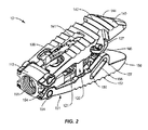
[0037]図1〜8に示されるように、拡張可能脊柱インプラント10、20の2つの例示的実施形態が示されている(インプラント10が、例示的な図1〜4において強調表示されており、インプラント20が例示的な図5〜8において強調表示されている)。図1〜2を参照すると、拡張可能脊柱インプラント10は、近位壁110と遠位壁120とを含む、フレーム100を備えてもよい。フレーム100は、拡張されると、インプラント10が、骨成長促進物質の事後パッキングのために、インプラントの近位端により近くに(例えば、少なくとも部分的にフレーム100内部などに)十分な余地を提供するように、拡張機構をインプラント10内の遠位に設置するための機構を提供してもよい。例えば、フレーム100の近位壁110は、骨成長促進物質をインプラント10の近位部分中にそれを通して導入することのできる挿入器具30の少なくとも一部を受け入れるのに適した、近位孔111を画定してもよい。さらに、フレームの遠位壁120は、プラグ130を受け入れるように適合された、遠位孔121(例えば、図2を参照)を画定してもよい。本明細書にさらに記載されるように、プラグ130は、フレームの遠位孔121内に移動可能に配置してもよい。
As shown in FIGS. 1-8, two exemplary embodiments of expandable
[0038]拡張可能脊柱インプラント10は、フレーム100と動作可能に係合されて、プラグ130が遠位方向D(図3〜4を参照)に移動されるときに、フレーム100から外向きに拡張するように構成された、第1のエンドプレート140をさらに備えてもよい。さらに、実施形態によっては、拡張可能脊柱インプラント10は、概略的に図1〜2に示されるように、対向する第1および第2のエンドプレート140、150を備えてもよい。拡張可能脊柱インプラント10のいくつかのそのような実施形態において、第2のエンドプレート150は、フレーム100と動作可能に係合させて、プラグ130が遠位方向Dに移動されるときに、フレーム100から外向きに拡張するように構成してもよい。さらに、図1に示されるように、第2のエンドプレート150は、フレーム100のまわりで、第1のエンドプレート140に対向して配置してもよく、ここで第1のエンドプレート140および第2のエンドプレート150は、インプラント10の近位端から、インプラント10の遠位端まで(インプラント10の長さLに沿って)延びて、少なくとも部分的にフレーム100を囲む。類似の構造が、図5〜8のインプラント20にも示されており、ここでエンドプレート240、250は協働して、少なくとも部分的にフレーム200を囲む(例えば、図5を参照)。様々なエンドプレート140、150、240、250には、隣接する椎体エンドプレート(図14および16に示されるようにV1、V2を参照)に合致するように、複数面内に凸状表面を設けてもよい。様々なエンドプレート140、150、240、250の表面は、一面にだけ凸部を備えるか、またはまったく凸部を備えずに構築することもできることを理解すべきである。さらに、エンドプレート140、150、240、250の椎体V1、V2接触表面には、それには限定されないが、稜、歯、穴、および(それには限定されないが、Medtronic plc販売のCapstone PTC(商標)インプラント上に設けられたもののような多孔質チタン被覆を含む)被覆を含む、様々な移動防止形体および/または骨結合形体を設けてもよい。
[0038] The expandable
[0039]図18は、フレーム100と動作可能に係合されて、プラグ130が遠位方向D(図3〜4を参照)に移動されるときにフレーム100から外向きに拡張するように構成された第1のエンドプレート140だけを備える、拡張可能脊柱インプラント10の実施形態を示す。図18の実施形態において、第2のエンドプレート150は、プラグ130が遠位方向に移動されると、(ピン154を経由してフレーム100にヒンジ付けされている)第1のエンドプレート140だけが拡張するように、フレーム100と一体形成し、かつ/またはフレーム100に対して移動不能としてもよい。そのような実施形態においては、遠位ヘッド部分135は、可動第1エンドプレート140と静止第2のエンドプレート150とを係合するように改変してもよい。例えば、図3Aに概略的に示されるように、可動の第1または第2のエンドプレート150(および/または相補的エンドプレート140)は、インプラント10が拡張されるときに、遠位ヘッド部分135の傾斜表面136がその上に圧をかける、傾斜表面153を備えてもよい。ランプ136/153機構は、インプラント10の開口および/または拡張を最適化するために、一対の横ポスト137とトラック145システム(図18を参照)と協働してもよい。
[0039] FIG. 18 is configured to be operably engaged with the
[0040]図1〜4を概略的に参照すると、エンドプレート140、150は、フレーム100の近位壁110の近く、またはその上に位置するヒンジ機構を経由してフレーム100と動作可能に係合させてもよい。例えば、プラグ130がインプラント10のフレーム100に対して遠位方向Dに移動されるときに、ピン154とピン孔112の協働によって、エンドプレート140、150がフレーム100に対して拡張可能となるように、エンドプレートが、フレーム100と動作可能に係合され、かつ/または互いにヒンジ結合されるように、フレーム100内に画定された対応するピン孔112に係合する、ピン154を設けてもよい。また、類似のヒンジ機構が、ピン孔212に係合されてフレーム200をエンドプレート240、250にヒンジ関係で接続するピン154を含む、図7〜8の実施形態に対しても、示されている。描かれた実施形態のいくつかにおいて多部品機械式ヒンジが示されているが、その他のタイプのヒンジおよび/または接続機構を使用して、フレーム100をインプラントの拡張可能なエンドプレート140、150に動作可能に結合してもよいことを理解すべきである。例えば、実施形態によっては、「一体ヒンジ(living hinge)」を使用してもよく、この場合には、エンドプレート140、150は、ヒンジ点においてはフレーム100と少なくとも部分的に一体的ではあるが、エンドプレート140、150がヒンジ接続のまわりに回転することを可能にする切抜きまたは屈曲点を備えて形成される。要約すると、フレーム100とエンドプレート140、150とは、それに限定はされないが、一体化接続、分離可能接続、締結具または接着剤を使用する機械式固定接続、(それに限定はされないが、キー溝および部分開放ヒンジを含む)解除可能接続およびその他の接続タイプを含む、多数の異なる方法で動作可能に係合させてもよい。実施形態によっては、フレーム100とエンドプレート140、150とは、3D印刷または焼結、レーザー/ビーム溶解、鋳造、押出しなどの付加製造(additive manufacturing)技法を使用して一体的に形成するか、または1種または複数種の原材料から除去製造(subtractive manufacturing)技法を使用して、一体形態に機械加工してもよい。
[0040] Referring schematically to FIGS. 1-4, the
[0041]実施形態によっては、拡張可能脊柱インプラント10のフレーム100は、近位壁110と遠位壁120とに係合された、少なくとも1つの側壁102をさらに備える。図3に概略的に示されるように、側壁102または壁102、104は、拡張可能脊柱インプラント10の(長さLに実質的および/または近似的に平行に延びる)縦方向軸に沿って、近位壁110と遠位壁120に間隔を空けるように構成してもよい。側壁102、104はまた、近位孔111を経由してインプラント10中に事前パックまたは事後パックしてもよい骨成長促進物質を、インプラント10の近位部分内に収納するように構成してもよい。側壁102、104はまた、近位壁110および遠位壁120と協働して、(図3〜4に示されるように、側方孔を画定してもよい)四辺フレーム100を生成してもよい。いくつかのそのような実施形態においては、フレームは、プラグ130が、フレーム100の遠位壁120に対して概して近位に設置されるときに、プラグ130の外部ねじ付き表面131と協働するように構成された内部ねじ103を画定してもよい。
[0041] In some embodiments, the
[0042]フレーム100は、実施形態によっては、インプラントが椎体間の円板空間内に設置された後に(例えば、図14および16に示される椎体V1とV2間でのインプラント10の設置を参照)、(例えば、フレーム100によって実質的に包囲される体積内の)インプラントの遠位部分を、骨成長促進物質で充填(または事後パック)されるように、開放または自由にできるように、インプラント10の全体長Lに対して実質的に遠位位置に、プラグ130を設置するのに特に有用である。図1、3、5および7を参照して本明細書において記述されるように、インプラント10、20は、その縦方向軸に沿って、その近位端110からその遠位端144まで延びる、長さLを含むか、または画定してもよい。いくつかのそのような実施形態においては、フレームの遠位壁120は、長さLの少なくとも3分の1(1/3)に(すなわち、図3および7に概略的に示されるように、距離Wだけ、近位端110から遠位方向に間隔を空けられた位置に)配置してもよい。他の実施形態において、フレームの遠位壁120は、それに限定はされないが、少なくとも、1/10、1/8、1/5、1/4、2/5、3/4、7/8および9/10を含む、長さLのその他の分数に(すなわち、図3および7に概略的に示されるように、距離Wだけ、近位端110から遠位方向に間隔を空けられた位置に)配置してもよい。その他の実施形態において、フレームの遠位壁120は、図3および7に概略的に示されるように、近位端110から距離Wだけ遠位方向に間隔を空けられた位置に配置してもよく、ここで距離Wは、距離Lの0から100パーセントの範囲であるが、場合によっては、距離Wは、距離Lの少なくとも0.25であって、プラグ130が遠位方向に移動されるときに、骨成長促進物質が、少なくとも部分的に距離Wによって画定されるエリア中に適切に事後パックされるために、インプラント10の近位部分内に空間を提供する。したがって、インプラント10の近位部分(少なくとも部分的にフレーム100によって画定される、内部体積など)は、プラグ130が遠位方向Dに移動された後に(プラグが初期位置にあることを示す図3と、プラグが遠位方向に移動されて、開放され、近位孔111と流体連通したままにされた、フレーム100体積をあらわにすることを示す図4とを参照)、骨成長促進物質をフレーム100の近位孔111を通り設置できるように、実質的に開放して、フレーム100の近位孔111と流体連通したままとしてもよい。
[0042] In some embodiments, the
[0043]他の実施形態において、図5〜8におけるインプラント20に対して示されるように、単一の側壁204が、図1〜4の2重壁実施形態を置換して、フレーム100の遠位壁120とフレームの近位壁110の間隔を空けてもよい。単一の側壁204を備える、いくつかのそのような実施形態においては、フレーム200は、インプラント10の片側に実質的に開放されており、フレーム200の開放側を経由しての、骨成長促進物質の挿入後パッキングを可能にする。(側壁204に概して対向して位置づけしてもよい)フレーム200の「開放」側または壁なし側は、インプラント20のフレーム200の近位孔211を通り、インプラント移植部位に導入してもよい、骨成長促進物質を誘導および/または収納するのにも使用してもよい。2つの側壁102、104を有する、「閉鎖された」実施形態と同様に、単一側壁204実施形態も、プラグ230が、フレーム200の遠位壁220に対して概して近位に位置づけされるときに、プラグ230の外部ねじ付き表面231と協働するように構成された、内部ねじ203を画定してもよい。
[0043] In another embodiment, as shown for
[0044]様々な実施形態において、拡張可能脊柱インプラント10、20内に設けられたプラグ130、230は、ねじ付き外部表面131(例えば、図1を参照)を含み、遠位孔121は、プラグ130のねじ付き外部表面131と動作可能に係合される、相補的なねじ付き内部表面を含んでもよい。プラグのねじ付き外部表面131は、プラグ130がフレーム100の遠位壁120に対して回転されるときに、プラグ130が図4に示されるように遠位方向Dに移動するように、プラグ130の近位端に配置してもよい。実施形態によっては、図4および8に示されるように、フレーム100は、遠位壁120と近位壁110を接続する側壁104を備えてもよく、この場合に、側壁104は、(特に、プラグが、フレーム100に対してなお近位に位置づけられているときに)プラグ130のねじ付き外部表面131と動作可能に係合するように構成された側壁ねじ付き表面103を含む。側壁ねじ付き表面203の代替実施形態も、図8に示されている。さらに、プラグ130は、プラグ130が遠位方向Dに移動されるときに、フレーム100から離れるようにエンドプレート140を付勢するように構成された遠位ヘッド部分135も備えてもよい。遠位ヘッド部分135は、実施形態によっては(図1〜4に概略的に示されるように)、エンドプレート140、150上の相補的な傾斜表面と連結するように構成されてもよい、傾斜表面136を有する、別個の構造を備えて構成してもよい。例えば、図3Aに示されるように、エンドプレート150(および相補的なエンドプレート140)は、インプラント10が拡張されるときに、遠位ヘッド部分135の傾斜表面136が、その上に圧をかける、傾斜表面153を備えてもよい。傾斜136/153機構は、インプラント10の開口および/または拡張を最適化するために、横ポスト137とトラック155のシステムと協働してもよい。例えば、ランプ136/153機構は、プラグ130が移動されるときに、横ポスト137とトラック155のシステムによって続いて支援されて、インプラントを拡張する、先導拡張機構を提供してもよい。さらに、横ポスト137とトラック155のシステムはまた、ランプ機構136/153機構によって提供される比較的緩やかな傾斜の斜面に沿って、エンドプレート140、150を、フレーム100に向かって内向きに引っ張ることによって、インプラント10の拡張を反転可能としてもよい。さらに、プラグ130は、プラグ130の近位部分(ねじ付き外部表面131を画定する部分など)が、フレーム100の遠位壁120の遠位孔121内で自由に回転できるのに対して、プラグの遠位ヘッド部分135が、回転なしにフレーム100に対して遠位方向に移動可能であるように、別個の接続要素132、133を備えてもよい。
[0044] In various embodiments, the
[0045]その他の実施形態において、図5〜8に概略的に示されているように、プラグ230には、テーパ付きシリンダを備える遠位ヘッド部分235を含めてもよい。いくつかのそのような実施形態において、遠位ヘッド部分235は、(例えば、外部ねじ付き表面231を画定する)近位部分がフレーム100に対して回転されて、遠位方向Dにプラグ230を駆動するときに、プラグ230と共に回転し、かつ/またはフレーム100に対して遠位方向Dにだけ移動するように構成してもよい。いくつかのそのような実施形態によれば、遠位ヘッド部分235は、エンドプレート240、250の内部表面上に画定された(場合によっては、ランプ表面および/または円錐台状凹面を含む、)輪郭形成された支持面253と協働するように構成してもよい。
[0045] In other embodiments, the
[0046]遠位ヘッド部分135、235は、プラグ130、230とエンドプレート140、150または240、250との間の容易な相互作用を可能にするために、様々な方法で、引込みテーパ(lead-in taper)または漸次テーパを設けるように構成してもよい。例えば、図3の部分的に分解された図に概略的に示されているように(ここで、第1のエンドプレート140は取り外されている)、遠位ヘッド部分135は、プラグ130がインプラント10の長さに沿って遠位方向に前進させられるときに、エンドプレート140を、フレーム100から離れるように徐々に移動させるように、相補的な傾斜表面または輪郭形成された表面153を、エンドプレート140、150(その中に形成された例示的なランプ153を備える1つのエンドプレート150の隔離図を示す、図3Aを参照)の内側に付勢するのに適したランプ136または楔を含む。同様に、図5〜8に示されている実施形態においては、遠位ヘッド部分235は、エンドプレート240、250をフレーム200から離れる方向に付勢するときに、実現しようとする機械的な利点を可能にする、テーパを用いて最適化されてもよい、引込み形状または円錐台状形状を提供するようにテーパ付けしてもよい。結果として得られるインプラント20の開放構成は、例えば、図6に示されている。さらに、様々なランプ構成および/またはテーパ構成を使用して、プラグ130、230と、エンドプレート140、150または240、250との相互作用を最適化してもよい。そのような構成としては、それに限定はされないが、順次ランプまたは異なる角度のテーパ付き円錐台状表面;(一旦、インプラント10の初期拡張が達成されると、機械的利点を増大させる)高角度順次ランプまたはテーパ付き円錐台状表面中に導く、浅い角度の順次ランプまたはテーパ付き円錐台状表面、ならびにその他の開口機構(インプラント20を拡張させる際に、結合してランプ136(および153、図3Aを参照)を支援することのできる、図2〜4に概略的に示されている、横ポスト137とトラック155のシステムなど)が挙げられる。
[0047]図2〜4に示されるように、拡張可能脊柱インプラント10のいくつかの実施形態においては、遠位ヘッド部分135は、プラグ130の遠位ヘッド部分135から延びて、エンドプレート140、150内に画定された対応するチャネル145、155と協働するように構成された、横ポスト137を備えてもよい。チャネルは、プラグ130がインプラント10の長さLに沿って遠位方向に前進させられるときに、インプラント10の拡張を支援するための追加の機構を提供するために、角度をつけるか、または部分的に角度をつけてもよい。図2をさらに詳細に参照すると、第1のエンドプレート140は、プラグ130が遠位方向に長さLに沿って移動されるときに、遠位ヘッド部分135の横ポスト137が横チャネル145内で第1の方向に移動されて、第1のエンドプレート140をフレーム100から外向きに拡張させるように、横ポスト137を受け入れるように構成された少なくとも1つの横チャネル145を画定してもよい。ポスト131とチャネル145の機構はまた、プラグ130が近位方向に(すなわち、フレーム100の遠位壁120に向かって)移動されるときに、遠位ヘッド部分135の横ポスト137が横チャネル145内で第2の方向に移動されて、第1のエンドプレート140をフレーム100に向かって収縮させる(この結果として、インプラント10は、図1に概略的に示される、閉鎖構成または非拡張構成に戻ることができる)ように、インプラント10拡張を実質的に反転可能にするのを支援してもよい。この反転可能機能は、プラグ130のねじ付き機構と合わされて、インプラント10を、(プラグ130の長さと、インプラント10のエンドプレートによって画定される、対応する支持面(例えば、図6、253を参照)とによってのみ限界が定められる)実質的に限界なしに調節可能な運動範囲にわたり、徐々に拡張または収縮させることを可能にする。
[0047] As shown in FIGS. 2-4, in some embodiments of the expandable
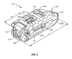
[0048]実施形態によっては、拡張可能脊柱インプラントシステム10、20は、挿入器具30で操作可能であり、かつ/またはそれによって挿入されるように構成してもよい(例えば、概略的に図17を参照)。いくつかのそのような実施形態において、図9に示されるように、拡張可能脊柱インプラント10は、近位壁110と遠位壁120とを含む、フレーム100を備えてもよい。近位壁110は、近位孔111をさらに画定し、遠位壁120は、遠位孔121をさらに画定してもよい。本明細書に記載されるように、近位孔111と遠位孔121の一方または両方を内部ねじ付きとして、他のねじ付き構成要素を受け入れてもよい。実施形態によっては、近位壁110は、挿入器具30(または、場合によっては、図9に示されるような挿入器具30の内部カニューレ320)を受け入れるように適合させてもよい。
[0048] Depending on the embodiment, the expandable
[0049]本明細書に記載されるように、拡張可能脊柱インプラント10は、遠位孔121内に移動可能に配置されたプラグ130を備えてもよく、このプラグ130は、挿入器具30の少なくとも一部分によって動作可能に係合されて、プラグ130を移動させるように適合された、インターフェイス134を含む。例えば、実施形態によっては、挿入器具30は、その遠位端に(ヘクサロビュラ(hexalobular)ドライバ先端などの)ドライバを備えるドライバシャフト330を備えてもよい。ドライバシャフト330の遠位端は、プラグ130のインターフェイス134と係合させて、インプラント10を拡張させるために、フレーム100の遠位孔121内でプラグを回転させてもよい。本明細書に記載されているように、インプラント10の拡張は、フレーム100によって動作可能に係合されて、プラグ130が挿入器具30(または、そのドライバシャフト330)によって移動されるときに、フレーム100に対して移動するように構成された、エンドプレート140、150を移動させることによって達成してもよい。
As described herein, the expandable
[0050]図17に概略的に示されるように、ドライバシャフト330は、挿入器具30の内部カニューレ320の内側に同軸に配置してもよい。さらに、ドライバシャフト330と内部カニューレ320の両方を、挿入器具30のカニューレ310の内側に同軸に配置してもよい。ドライバシャフト330、内部カニューレ320およびカニューレ310のそれぞれには、様々な操作構成要素330’、320’および310’をそれぞれさらに設けて、それによって、挿入器具30の様々な構成要素を動作させ、かつ/または互いに独立に選択的に操作して、(本明細書にさらに記述されるように)インプラント10に対する様々な機能を実行してもよい。
[0050] As schematically shown in FIG. 17, the
[0051]本明細書に記載されて、図3および7の実施形態に示されるように、フレーム100、200は、フレーム100の近位壁110および遠位壁120と係合された、少なくとも1つの側壁104、204をさらに備えてもよい。側壁104、204は、インプラント10、20の(長さLに平行に延びる)縦方向軸に沿って、フレーム100の近位壁110と遠位壁120の間隔を空けるように構成してもよい。実施形態によっては、図3に示されるように、フレーム100は、横方向に間隔を空けられて、フレーム100の近位壁110および遠位壁120と係合された、一対の側壁102、104を備えて、フレーム100の近位孔111を通して設置してもよい骨成長促進物質を受け入れ、かつ/または収納するように適合された、実質的に閉鎖されたエリアを形成してもよい。実施形態によっては、挿入器具30のカニューレ310または内部カニューレ320は、インプラント10が拡張位置にあるときに(例えば、遠位方向前方に、フレーム100によって画定されるインプラント10の近位エリアから外に、移動されるプラグ130を示す図2を参照)、骨成長促進物質を、挿入器具30を通してフレーム100によって画定されるエリア中に移送するように構成してもよい。
[0051] As described herein and shown in embodiments of FIGS. 3 and 7, the
[0052]実施形態によっては、フレーム100は、図9〜12に概略的に示されるように、側壁によって実質的に「閉鎖」されてもよい。その他の実施形態においては、フレーム100は、図1〜4に概略的に示されるように、横孔を有する一対の側壁102、104を備えてもよい。その他の実施形態においては、図5〜8に示されるように、フレーム200は、一方向または単一の側壁204を備えて、1つの「開放された」横側を有する、フレーム200を形成してもよい。図8に示されるそのような実施形態においては、フレーム200は、フレーム200の近位孔211を通して設置してもよい、骨成長促進物質BGを少なくとも部分的に収納し、かつ/またはフレーム200の近位壁210と遠位壁220の間で横方向に、拡張可能脊柱インプラント20の外側に、骨成長促進物質BGを誘導するように適合させてもよい。
[0052] In some embodiments, the
[0053]図9〜12は、挿入器具30と一緒に使用されて、一実施形態による拡張可能脊柱インプラントシステムを形成する、インプラント10実施形態の様々な構成を示す。図9に概略的に示されるように、このシステムは、(本明細書において記載されるような、内部カニューレ320および外部カニューレ310を含め得る)カニューレ310と、カニューレ310内部に着脱可能および回転可能に配置されたドライバシャフト330(図10および17を参照)を含む、挿入器具30を備えてもよい。このシステムは、多種多様な機構を使用して挿入器具30と動作可能に係合されるように構成された、拡張可能脊柱インプラント10をさらに備えてもよい。本明細書に記載されるように、インプラント10は、近位壁110および遠位壁120を含むフレーム100を備え、近位壁110は近位孔111を画定し、遠位壁120は遠位孔を画定する。近位壁110は、拡張可能脊柱インプラント10を操作するために、カニューレ310(または中央カニューレ320)の遠位端を受け入れるように構成してもよい。例えば、図9に示されるように、カニューレ310は、フレーム100の近位壁110によって画定される相補的リセプタクル114中への挿入のために構成された、プロング(prong)311を備えてもよい。その他の実施形態において、プロング311は、エンドプレート140、150によって画定されるタブまたはスロットと相互作用してもよい。プロング311は、インプラント10が挿入器具の遠位端と係合されるときに、外科医がインプラント10を有効に操作することを可能にするために、リセプタクル114と相互作用してもよい。さらに、実施形態によっては、内部カニューレ320は、フレーム100の近位孔111のねじ付き内部表面と動作可能に係合させるために構成された、ねじ付き先端321を備えてもよい。いくつかのそのような実施形態においては、カニューレのプロング311は、内部カニューレ320が回転されて、フレーム100の近位孔111と係合するときに、有効な(挿入器具30に対するインプラント10の回転を防止する)逆トルク(counter-torque)デバイスとしての役割を果たすことができる。図17は、挿入器具の操作構成要素330’、320’および310’を含むインプラント10に関係して、挿入器具30を示す。例えば、インプラント10を回転させることなく、ねじ付き先端321を、フレーム100の近位孔111と係合させ得るように、内部カニューレ320のノブ320’が外部カニューレ310内部で回転されるときでも、外部カニューレ310のハンドル310’は、インプラント10を安定化および/または操作するのに使用することができる。
[0053] FIGS. 9-12 show various configurations of the
[0054]本明細書に記載されるように、インプラント10は、フレーム100の遠位孔120内に移動可能に配置されたプラグ130によって拡張するように構成してもよい。実施形態によっては、プラグは、遠位孔120の相補的な内部ねじ付き表面と係合するように構成された、ねじ付き外部表面131を備える。実施形態によっては、図9に示されるように、プラグ130は、ドライバシャフト330の遠位端によって動作可能に係合されて、プラグ130を(例えば、ねじ付き回転によって)フレームに対して移動させるように構成された、インターフェイス134を備えてもよい。ドライバシャフト330は、カニューレ310および/または内部カニューレ310内部に同軸に設置して、ドライバシャフト330のドライバ近位端330’を使用してその中で回転可能にしもよい。ドライバ近位端330’は、迅速解除ハンドル(図示せず)、またはドライバシャフト330を回転させるためのパワードライバ(図示せず)との係合用に構成された、キー付きまたは刻面された(faceted)表面を備えてもよい。さらに、プラグインターフェイス134は、ドライバシャフトの遠位端と協働するように構成された、ドライブリセプタクルを備えてもよい。ドライバシャフト330とプラグインターフェイス134の間のドライブ接続は、それに限定はされないが、マルチロビュラ(multi-lobular)ドライブ、ヘクサロビュラドライブ、クロスヘッドドライブもしくはPhillipsヘッドドライブ、ストレートドライブもしくは「フラットヘッド」ドライブ、正方形ドライブもしくはその他の多角形ドライブ、および/またはそれらの組合せを含む、多様なドライブインターフェイスを備えてもよい。
[0054] As described herein, the
[0055]本明細書に記載されるように、カニューレ310(および、場合によっては、内部カニューレ320)内部でドライバシャフト310によって促進されたプラグ130の移動は、プラグ130が挿入器具30によって移動されるときに、フレーム100に対する、インプラント10のフレーム100と動作可能に係合されたエンドプレート140、150の移動をさらに生じさせる。すなわち、挿入器具30(またはドライバシャフト330およびドライバ近位端330’)を、インプラント10を選択的に拡張させるため、および/または図14および16に概略的に示されるように、隣接する椎体V1、V2における前弯移動を付与するために、フレーム100に対してエンドプレート140、150を拡張させるのに使用してもよい。ドライバシャフト330の長さは、インプラント10の長さLに対して、フレーム100の遠位壁120の遠位設置を考慮に入れるために調節してもよい。例えば、ドライバシャフト330には、カニューレ310および/内部カニューレ320の長さを実質的に超える長さを与えて、それによって、インプラントが完全に拡張された状態にあるときに(図14および16を参照)、ドライバシャフト330がインプラント10のプラグ130と係合されたままのときでも、ドライバ近位端330’が、アクセス可能であって、ハンドルまたはパワードライバと係合されたままとなるようにしてもよい。この機能は、特定のインプラント10実施形態のポスト131とチャネル145の機構について、本明細書においてさらに記述されるように、外科医が、インプラント10の拡張を反転させたい状況において重要であり得る。
[0055] As described herein, the movement of the
[0056]様々な実施形態によれば、インプラント10のプラグ130がフレーム100に対して遠位方向に移動された後に、骨成長促進物質BGを、カニューレ310を通して(および/または、用いられるときには、内部カニューレ320を通して)拡張可能脊柱インプラント10のフレーム100中に導入できるように、ドライバシャフト330は、カニューレ310(および/または内部カニューレ(使用されている場合))から着脱可能に構成してもよい。骨成長促進物質BGは、ドライバシャフト330、またはカニューレ310および/または内部カニューレ310を通り摺動可能に挿入するために寸法決めされたその他のタンプ(tamp)および/またはロッド(図示せず)を使用して、カニューレ310または内部カニューレ310を通してタンピングまたは付勢してもよい。漏斗(図示せず)またはその他のアタッチメントを、(図17に示されるように、内部カニューレ320の近位端またはノブ320’の近くの点におけるなど)カニューレ310または内部カニューレ320の近位端中に挿入して、骨成長促進物質BGのカニューレ310および/または内部カニューレ320中への導入を容易化してもよい。
[0056] According to various embodiments, after the
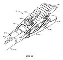
[0057]図9〜12は、一実施形態におけるインプラントシステムの使用のための例示的な処置ステップを示す。例えば、図9は、カニューレ310のプロング311および内部カニューレ320の遠位端321を使用して挿入器具30に取り付けられた、非拡張状態のインプラント10を示す。プラグ130は、フレームの遠位壁120の遠位孔に係合されているのが示されており、プラグインターフェイス134は見ることができる。図10において、ドライバシャフト330は、カニューレ310および内部カニューレ320を通り延長されて、プラグインターフェイス134と係合された状態で示されている。図17を参照すると、ドライバ近位端330’は、プラグ130を前方に駆動して、フレーム100に対してエンドプレート140、150を拡張するために、このステップにおいて回転させてもよい。図11は、ドライバシャフト330とプラグ130との相互作用の結果と、エンドプレート140、150をインプラント10のフレーム100に対して拡張するための、フレーム100の遠位壁120に対するプラグ130の遠位方向移動とを示している。図12は、インプラント10となお係合されているが、ドライバシャフト330がカニューレ310および内部カニューレ320から取り外された、挿入器具30を示しており、カニューレは、挿入器具30を通して、フレーム100の現在開放された内部によって概略的に画定されたインプラント10の近位部分中に骨成長促進物質BGを導入するために、解放状態にされたままである。
[0057] FIGS. 9-12 show exemplary treatment steps for the use of the implant system in one embodiment. For example, FIG. 9 shows a
[0058]図13〜16を参照すると、脊柱インプラントシステム10、30は、例えば、椎骨V1と椎骨V2の間の椎体間円板空間などの、身体内部の脊柱の患部および隣接するエリアの応用可能な状態または傷害の治療のための、例えば、椎体間固定などの、外科的関節固定処置に用いることができる。実施形態によっては、脊柱インプラントシステム10、30は、椎骨間円板空間に挿入して関節表面の間隔を空けることのできる椎骨間インプラントを備えて、支持を与えて、椎骨V1、V2の安定性を最大化することができる。実施形態によっては、脊柱インプラントシステム10、30は、1つまたは複数の椎骨に用いてもよい。
[0058] With reference to FIGS. 13-16,
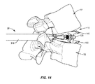
[0059]医師は、組織の切除および退縮などによって、椎骨V1、V2を含む手術部位までのアクセスを得る。脊柱インプラントシステム10、30は、オープン手術、ミニオープン手術、最小侵襲手術および経皮的外科移植を含む、任意既存の手術方法または技法において使用可能であり、それによって、椎骨V1、V2は、エリアまでの保護された通路を提供する、ミニ切除、縮退、チューブまたはスリーブを通してアクセスされる。一実施形態において、脊柱インプラントシステム10、30の構成要素は、手術アプローチに沿って手術部位への手術経路を通り、椎骨V1とV2の間の椎骨間円板空間中に送達される。様々な手術アプローチおよび経路を使用してもよい。図13は、脊柱インプラントシステム10、30を使用する、典型的な後方進入腰椎椎間固定(PLIF)アプローチを示し、この場合には、一対のインプラント10が送達され、拡張されて、前弯曲線(概略は図14を参照)を付与または回復し、次いで、ドライバシャフト330を挿入器具30から取り外した後に、骨成長促進物質BGで事後パックされる。図15に示されるように、経椎間孔腰椎椎体間固定(TLIF)アプローチなどの一方向アプローチも、インプラントを、椎骨V1、V2に対して実質的に斜め位置に設置するのに使用することもできる。そのような処置において、エンドプレート140、150の遠位端144は、インプラント10が、図15に示されるように椎体V2の広がりによって画定される椎骨間空間内部に嵌るように、成形してもよい。さらに、斜め設置用途において、インプラント10エンドプレート140、150にも、図16に概略的に示されるように、インプラント10が拡張されるときに、前弯曲線をより良く付与および/または回復するように成形された、相補的な斜め接触面を設けてもよい。さらに、インプラントのエンドプレート140、150には、多様な稜、歯、被覆、または隣接する椎骨V1、V2と相互作用し、かつ/またはそれに対して固定するのに適するその他の表面処理物を設けてもよい。
[0059] The doctor gains access to the surgical site including the vertebrae V1 and V2 by excision and regression of the tissue.
[0060]当業者は気付くように、システム10、30を使用する処置の準備に際して、準備機器(図示せず)を用いて、円板組織、流体、隣接組織および/または骨を除去し、椎骨V1のエンドプレート表面および/または椎骨V2のエンドプレート表面から組織を掻取りおよび/または除去してもよい。実施形態によっては、インプラント10の寸法は、(例えば、図17に示されるような)システム10、30の寸法および構成を近似することのできる、トライアル器具(図示せず)を使用するトライアルの後に選択される。実施形態によっては、そのようなトライアルは、寸法を固定し、かつ/または本明細書に記載された様々なインプラント10、20実施形態と類似の拡張機構に適合させてもよい。実施形態によっては、インプラント10は、蛍光透視法によって可視化して、椎骨間円板空間中に導入する前に、方向を決めてもよい。さらに、挿入器具30およびインプラント10は、基準マーカーに適合させて、処置前および/または処置中に、画像案内式手術ナビゲーションを可能にしてもよい。
[0060] Those skilled in the art will notice that in preparation for the
[0061]図13および15に概略的に示されるようないくつかの実施形態においては、インプラント10は、安定性を向上させるとともに、組織中への沈下のリスクを低減する、底面積を有する。図14および16に概略的に示されるようないくつかの実施形態においては、インプラント10は、角度矯正、椎体間の高さ回復、減圧、サジタルバランスおよび/またはコロナルバランスの回復、ならびに/または椎骨エンドプレート中への沈下の抵抗をもたらす。実施形態によっては、インプラント10は、椎骨V1、V2の対向するエンドプレート表面を係合させ、かつ間隔を空けるとともに、椎骨空間内部で固定されて、椎骨V1、V2の融合および固定のための骨成長に関して、椎骨V1、V2の部分を安定化し、かつ不動化する。
[0061] In some embodiments, as schematically shown in FIGS. 13 and 15, the
[0062]インプラント10を含む、脊柱インプラントシステム10、30の構成要素は、事前組立デバイスとしての送達または移植が可能であるか、またはin situでの組み立てが可能である。インプラント10を含む、脊柱インプラントシステム10、30の構成要素は、in situで、拡張、収縮、完全または部分的な修正、取り外し、または交換を行ってもよい。実施形態によっては、脊柱インプラントシステム10、30の構成要素の1つまたは全部は、機械的操作および/またはフリーハンド技術によって、手術部位に送達することができる。
[0062] The components of the
[0063]一実施形態において、脊柱インプラントシステム10、30は、複数のインプラント10を含む(一例として図13を参照)。実施形態によっては、複数のインプラント10を用いることによって、椎骨V1、V2間の角度矯正および/または高さ回復を最適化することができる。複数のインプラント10は、横並び係合状態で配向させ、間隔を空けて、かつ/または互い違いに配置することができる。
[0063] In one embodiment, the
[0064]実施形態によっては、脊柱インプラントシステム10、30は、それには限定されないが、本明細書において記載された骨成長促進物質BGを含む、用剤を含み、この用剤は、脊柱インプラントシステム10、30の構成要素および/または表面の内部、上、またはまわりに配置、パッキング、被覆または積層してもよい。実施形態によっては、この用剤には、インプラント10と骨構造の固定を強化するために、骨成長促進物質を含めてもよい。実施形態によっては、この用剤には、例えば、疼痛、炎症および変性を治療するための、持続的放出を含む、放出のための1種または複数種の治療剤および/または薬剤を含めてもよい。
[0064] In some embodiments,
[0065]一実施形態において、インプラント10、20には締結要素を含めてもよく、この締結要素には、関節表面を固めて、椎骨領域に相補的な安定化と不動化をもたらすために、椎骨V1、V2との固定用に構成されたロック構造を含めてもよい。実施形態によっては、ロック構造には、例えば、ロッド、プレート、クリップ、フック、接着剤および/またはフランジなどの、締結要素を含めてもよい。実施形態によっては、脊柱インプラントシステム10、30の構成要素は、固定を強化するために、ねじと共に使用することができる。脊柱インプラントシステム10の構成要素は、ポリマーなどの、放射線透過性材料で製作することができる。放射性不透過性マーカーを、X線、蛍光透視、CTまたはその他の撮像技術の下で識別用に含めてもよい。
[0065] In one embodiment,
[0066]実施形態によっては、顕微鏡手術による、最小侵襲および画像案内技術を用いて、脊柱インプラントシステム10、30の支援により、脊柱劣化または損傷にアクセス、観察および補修を行ってもよい。処置を完了すると、脊柱インプラントシステム10、30の非移植構成要素、手術器具、および(挿入器具30などの)組立体を取り外し、切り口が閉じられる。実施形態によっては、外科医が、リアルタイムまたは、ほぼリアルタイムで患者の解剖学的構造に対する、インプラント10、20の投影軌跡または挿入経路を見ることができるように、開示された様々な機器(図9および関係する図において本明細書で概略的に開示された挿入器械など)に、(それには限定されないが、Medtronic plc販売のSTEALTHSTATION(登録商標)ナビゲーションシステムを含む、)手術ナビゲーションシステムでの使用に適する、基準マーカーまたはその他の要素を設けてもよい。
[0066] In some embodiments, minimally invasive and imaging techniques by microsurgery may be used to access, observe and repair spinal deterioration or injury with the assistance of
[0067]本明細書において記載された、拡張可能脊柱インプラント10、20、システムおよび挿入器具30の様々な独立の構成要素は、様々な実施形態に従って、異なる方法で組み合わせてもよいことが理解されるであろう。非限定の例として、インプラント20について、図5〜8に示されるノッチ114は、図1〜4に示されるインプラント10の近位端に加えてもよい。さらなる非限定の例として、インプラント20のエンドプレート240、250について、図5〜8に示される二重孔241a、241b、251a、251bは、図1〜4に示されるインプラント10のエンドプレート140、150にも追加してもよい。
It is understood that the various independent components of the expandable
[0068]本明細書において開示された実施形態に対して、様々な修正を行ってもよいことが理解されるであろう。したがって、上記の説明は、限定を意味するとは解釈すべきではなく、様々な実施形態の例示にすぎないものである。当業者は、本明細書の特許請求の範囲の範囲と趣旨の中で、その他の修正案を思いつくであろう。 [0068] It will be appreciated that various modifications may be made to the embodiments disclosed herein. Therefore, the above description should not be construed as implying limitation, but merely exemplifies various embodiments. Those skilled in the art will come up with other amendments within the scope and intent of the claims herein.
Claims (18)
前記遠位孔内に移動可能に配置されたプラグと、
前記フレームと動作可能に係合されて、前記プラグが遠位方向に移動されるときに前記フレームから外向きに拡張するように構成された、第1のエンドプレートと、
前記フレームと動作可能に係合されて、前記プラグが遠位方向に移動されるときに、前記フレームから外向きに拡張するように構成され、前記フレームのまわりに、前記第1のエンドプレートと対向して配置された、第2のエンドプレートであって、前記第1のエンドプレートおよび前記第2のエンドプレートは、前記インプラントの近位端から前記インプラントの遠位端へと延びて、少なくとも部分的に前記フレームを囲んでいる、第2のエンドプレートと、
前記プラグの遠位端に提供され、前記第1のエンドプレートの内面と前記第2のエンドプレートの内面の両方に係合するようになっている、遠位ヘッド部分とを備え、
前記第1のエンドプレートおよび前記第2のエンドプレートが前記フレームから外向きに拡張するとき、前記第1のエンドプレートの遠位端と前記第2のエンドプレートの遠位端だけが互いに離れるように拡張し、前記第1のエンドプレートの近位端と前記第2のエンドプレートの近位端は互いに離れるように拡張せず、
前記第1のエンドプレートの遠位端と前記第2のエンドプレートの遠位端との間の拡張は、前記遠位ヘッド部分により、前記第1のエンドプレートの内面と前記第2のエンドプレートの内面の両方を押圧することによりなされる、
拡張可能脊柱インプラント。 A frame comprising a proximal wall and a distal wall, wherein the distal wall defines a distal hole.
With a plug movably arranged in the distal hole,
With a first end plate operably engaged with the frame and configured to extend outward from the frame as the plug is moved distally.
Operatively engaged with the frame and configured to extend outward from the frame as the plug is moved distally, with the first end plate around the frame. Opposing second end plates, the first end plate and the second end plate extending from the proximal end of the implant to the distal end of the implant, at least. A second end plate that partially surrounds the frame,
It comprises a distal head portion provided at the distal end of the plug that engages both the inner surface of the first end plate and the inner surface of the second end plate.
When the first end plate and the second end plate extend outward from the frame, only the distal ends of the first end plate and the distal ends of the second end plate are separated from each other. The proximal end of the first end plate and the proximal end of the second end plate did not extend apart from each other.
The extension between the distal end of the first end plate and the distal end of the second end plate is due to the distal head portion to the inner surface of the first end plate and the second end plate. Made by pressing both of the inner surfaces of the
Expandable spinal implant.
前記遠位孔に移動可能に配置されたプラグであって、前記プラグを移動させるための前記挿入器具の少なくとも一部分によって動作可能に係合されるように構成されたインターフェイスを含む、プラグと、
前記フレームと動作可能に係合されて、前記プラグが前記挿入器具によって移動されるときに、前記フレームに対して外向きに移動するように構成された、第1のエンドプレートおよび第2のエンドプレートと、
前記プラグの遠位端に提供され、前記第1のエンドプレートの内面と前記第2のエンドプレートの内面の両方に係合するようになっている、遠位ヘッド部分と、
を備え、
前記第1のエンドプレートおよび前記第2のエンドプレートが前記フレームに対して外向きに移動するとき、前記第1のエンドプレートの遠位端と前記第2のエンドプレートの遠位端だけが互いに離れるように拡張し、前記第1のエンドプレートの近位端と前記第2のエンドプレートの近位端は互いに離れるように拡張せず、
前記第1のエンドプレートの遠位端と前記第2のエンドプレートの遠位端との間の拡張は、前記遠位ヘッド部分により、前記第1のエンドプレートの内面と前記第2のエンドプレートの内面の両方を押圧することによりなされる、
拡張可能脊柱インプラント。 A frame comprising a proximal wall and a distal wall, wherein the proximal wall defines a proximal foramen, the distal wall defines a distal foramen, and the proximal wall is the expandable spinal column. With a frame, which is adapted to accept insertion devices for manipulating implants,
A plug comprising an interface that is movably disposed in the distal hole and is configured to be operably engaged by at least a portion of the insertion device for moving the plug.
A first end plate and a second end configured to operably engage with the frame and move outward with respect to the frame as the plug is moved by the insert. and the plate,
A distal head portion provided at the distal end of the plug and adapted to engage both the inner surface of the first end plate and the inner surface of the second end plate.
With
When the first end plate and the second end plate move outward with respect to the frame, only the distal ends of the first end plate and the distal ends of the second end plate are relative to each other. Expanded apart, the proximal end of the first end plate and the proximal end of the second end plate did not extend apart from each other.
The extension between the distal end of the first end plate and the distal end of the second end plate is due to the distal head portion to the inner surface of the first end plate and the second end plate. Made by pressing both of the inner surfaces of the
Expandable spinal implant.
拡張可能脊柱インプラントであって、
近位壁と遠位壁とを含む、フレームであって、前記近位壁が近位孔を画定し、前記遠位壁が遠位孔を画定するとともに、前記近位壁が前記拡張可能脊柱インプラントを操作するための前記カニューレの遠位端を受け入れるように構成されている、フレームと、
前記遠位孔内に移動可能に配置されたプラグであって、前記フレームに対してプラグを移動させるために前記ドライバシャフトの遠位端によって動作可能に係合されるように構成されたインターフェイスを含む、プラグと、
前記フレームと動作可能に係合されて、前記プラグが前記挿入器具によって移動されるときに、前記フレームに対して外向きに移動するように構成された、第1のエンドプレートおよび第2のエンドプレートと、
前記プラグの遠位端に提供され、前記第1のエンドプレートの内面と前記第2のエンドプレートの内面の両方に係合するようになっている、遠位ヘッド部分と、
を含む、拡張可能脊柱インプラントとを備え、
前記第1のエンドプレートおよび前記第2のエンドプレートが前記フレームに対して外向きに移動するとき、前記第1のエンドプレートの遠位端と前記第2のエンドプレートの遠位端だけが互いに離れるように拡張し、前記第1のエンドプレートの近位端と前記第2のエンドプレートの近位端は互いに離れるように拡張せず、
前記ドライバシャフトは、前記プラグが前記フレームに対して遠位方向に移動された後に、骨成長促進物質を、前記カニューレを通して前記拡張可能脊柱インプラントの前記フレーム中に導入できるように、前記カニューレから脱着可能に構成され、
前記第1のエンドプレートの遠位端と前記第2のエンドプレートの遠位端との間の拡張は、前記遠位ヘッド部分により、前記第1のエンドプレートの内面と前記第2のエンドプレートの内面の両方を押圧することによりなされる、
拡張可能脊柱インプラントシステム。
An insertion instrument comprising a cannula and a removable and rotatable driver shaft inside the cannula.
An expandable spinal implant
A frame comprising a proximal wall and a distal wall, wherein the proximal wall defines a proximal foramen, the distal wall defines a distal foramen, and the proximal wall is the expandable spinal column. With a frame, which is configured to receive the distal end of the cannula for manipulating the implant,
An interface that is movably disposed within the distal hole and is configured to be operably engaged by the distal end of the driver shaft to move the plug relative to the frame. Including, plug and
A first end plate and a second end configured to operably engage with the frame and move outward with respect to the frame as the plug is moved by the insert. and the plate,
A distal head portion provided at the distal end of the plug and adapted to engage both the inner surface of the first end plate and the inner surface of the second end plate.
Equipped with expandable spinal implants, including
When the first end plate and the second end plate move outward with respect to the frame, only the distal ends of the first end plate and the distal ends of the second end plate are relative to each other. Expanded apart, the proximal end of the first end plate and the proximal end of the second end plate did not extend apart from each other.
The driver shaft is detached from the cannula so that after the plug has been moved distal to the frame, the bone growth promoter can be introduced through the cannula into the frame of the expandable spinal implant. to be able to be configured,
The extension between the distal end of the first end plate and the distal end of the second end plate is due to the distal head portion to the inner surface of the first end plate and the second end plate. Made by pressing both of the inner surfaces of the
Expandable spinal implant system.
Priority Applications (1)
| Application Number | Priority Date | Filing Date | Title |
|---|---|---|---|
| JP2021118709A JP2021166836A (en) | 2015-10-16 | 2021-07-19 | Expandable spinal implant system and method |
Applications Claiming Priority (3)
| Application Number | Priority Date | Filing Date | Title |
|---|---|---|---|
| US14/885,472 | 2015-10-16 | ||
| US14/885,472 US10610376B2 (en) | 2015-10-16 | 2015-10-16 | Expandable spinal implant system and method |
| PCT/US2016/056869 WO2017066463A1 (en) | 2015-10-16 | 2016-10-13 | Expandable spinal implant system and method |
Related Child Applications (1)
| Application Number | Title | Priority Date | Filing Date |
|---|---|---|---|
| JP2021118709A Division JP2021166836A (en) | 2015-10-16 | 2021-07-19 | Expandable spinal implant system and method |
Publications (2)
| Publication Number | Publication Date |
|---|---|
| JP2018530384A JP2018530384A (en) | 2018-10-18 |
| JP6924749B2 true JP6924749B2 (en) | 2021-08-25 |
Family
ID=58518374
Family Applications (2)
| Application Number | Title | Priority Date | Filing Date |
|---|---|---|---|
| JP2018516028A Active JP6924749B2 (en) | 2015-10-16 | 2016-10-13 | Expandable spinal implant system and method |
| JP2021118709A Pending JP2021166836A (en) | 2015-10-16 | 2021-07-19 | Expandable spinal implant system and method |
Family Applications After (1)
| Application Number | Title | Priority Date | Filing Date |
|---|---|---|---|
| JP2021118709A Pending JP2021166836A (en) | 2015-10-16 | 2021-07-19 | Expandable spinal implant system and method |
Country Status (6)
| Country | Link |
|---|---|
| US (3) | US10610376B2 (en) |
| EP (1) | EP3362000B1 (en) |
| JP (2) | JP6924749B2 (en) |
| CN (2) | CN108135710B (en) |
| AU (2) | AU2016339970B2 (en) |
| WO (1) | WO2017066463A1 (en) |
Families Citing this family (71)
| Publication number | Priority date | Publication date | Assignee | Title |
|---|---|---|---|---|
| US9801733B2 (en) | 2005-03-31 | 2017-10-31 | Life Spine, Inc. | Expandable spinal interbody and intravertebral body devices |
| US11304818B2 (en) | 2013-03-13 | 2022-04-19 | Life Spine, Inc. | Expandable spinal interbody assembly |
| US10426632B2 (en) | 2013-03-13 | 2019-10-01 | Life Spine, Inc. | Expandable spinal interbody assembly |
| US10154911B2 (en) | 2013-03-13 | 2018-12-18 | Life Spine, Inc. | Expandable implant assembly |
| US10383741B2 (en) | 2013-03-13 | 2019-08-20 | Life Spine, Inc. | Expandable spinal interbody assembly |
| US11311312B2 (en) | 2013-03-15 | 2022-04-26 | Medtronic, Inc. | Subcutaneous delivery tool |
| US9987143B2 (en) | 2013-03-15 | 2018-06-05 | Spectrum Spine Ip Holdings, Llc | Expandable inter-body fusion devices and methods |
| US10492917B2 (en) | 2013-09-26 | 2019-12-03 | Warsaw Orthopedic, Inc. | Intrabody osteotomy implant and methods of use |
| US10575964B2 (en) | 2014-10-28 | 2020-03-03 | Spectrum Spine Ip Holdings, Llc | Expandable, adjustable inter-body fusion devices and methods |
| US10285824B2 (en) * | 2014-10-28 | 2019-05-14 | Spectrum Spine Ip Holdings, Llc | Expandable, adjustable inter-body fusion devices and methods |
| US10500061B2 (en) * | 2015-08-13 | 2019-12-10 | K2M, Inc. | Adjustable spinal implant |
| US10610376B2 (en) * | 2015-10-16 | 2020-04-07 | Warsaw Orthopedic, Inc. | Expandable spinal implant system and method |
| US9974662B2 (en) * | 2016-06-29 | 2018-05-22 | Globus Medical, Inc. | Expandable fusion device and method of installation thereof |
| US10052215B2 (en) * | 2016-06-29 | 2018-08-21 | Globus Medical, Inc. | Expandable fusion device and method of installation thereof |
| WO2018015964A1 (en) | 2016-07-21 | 2018-01-25 | Nlt Spine Ltd. | Expandable implant |
| FR3058043B1 (en) * | 2016-10-27 | 2020-11-13 | Ldr Medical | EXPANDABLE INTERSOMATIC CAGE |
| FR3058044A1 (en) * | 2016-10-27 | 2018-05-04 | Ldr Medical | EXPANDABLE INTERSOMATIC CAGE |
| US10238503B2 (en) | 2016-11-01 | 2019-03-26 | Warsaw Orthopedic, Inc. | Expandable spinal implant system with a biased tip and method of using same |
| EP3614975A1 (en) * | 2017-04-25 | 2020-03-04 | Life Spine, Inc. | Expandable spinal interbody assembly |
| US10398563B2 (en) * | 2017-05-08 | 2019-09-03 | Medos International Sarl | Expandable cage |
| US11896494B2 (en) | 2017-07-10 | 2024-02-13 | Life Spine, Inc. | Expandable implant assembly |
| US11033403B2 (en) | 2017-07-10 | 2021-06-15 | Life Spine, Inc. | Expandable implant assembly |
| US10575962B2 (en) | 2017-11-20 | 2020-03-03 | Warsaw Orthopedic, Inc. | Spinal implant |
| WO2019165157A1 (en) | 2018-02-22 | 2019-08-29 | Warsaw Orthopedic, Inc. | Expandable spinal implant system and method of using same |
| US11806250B2 (en) | 2018-02-22 | 2023-11-07 | Warsaw Orthopedic, Inc. | Expandable spinal implant system and method of using same |
| CN111655203A (en) * | 2018-02-22 | 2020-09-11 | 华沙整形外科股份有限公司 | Expandable spinal implant system and method of use |
| USD870889S1 (en) | 2018-03-02 | 2019-12-24 | Restor3D, Inc. | Cutout airway stent |
| US10183442B1 (en) | 2018-03-02 | 2019-01-22 | Additive Device, Inc. | Medical devices and methods for producing the same |
| USD870890S1 (en) | 2018-03-02 | 2019-12-24 | Restor3D, Inc. | Spiral airway stent |
| USD871577S1 (en) | 2018-03-02 | 2019-12-31 | Restor3D, Inc. | Studded airway stent |
| USD870888S1 (en) | 2018-03-02 | 2019-12-24 | Restor3D, Inc. | Accordion airway stent |
| US10695103B2 (en) | 2018-03-29 | 2020-06-30 | Warsaw Orthopedic, Inc. | Motion control and vertebral fixation device |
| WO2019210235A1 (en) * | 2018-04-27 | 2019-10-31 | Kleiner Device Labs, Llc. | Tools for spinal surgery |
| US10889053B1 (en) | 2019-03-25 | 2021-01-12 | Restor3D, Inc. | Custom surgical devices and method for manufacturing the same |
| USD955579S1 (en) | 2019-04-26 | 2022-06-21 | Warsaw Orthopedic, Inc. | Surgical implant |
| USD948048S1 (en) | 2019-04-26 | 2022-04-05 | Warsaw Orthopedic, Inc. | Surgical implant |
| EP3979951A1 (en) | 2019-06-10 | 2022-04-13 | Life Spine, Inc. | Expandable implant assembly with compression features |
| US11439515B2 (en) * | 2019-08-01 | 2022-09-13 | Spineology Inc. | Variable lordotic angular expanding implant with centralized graft deployment channel |
| US11523910B2 (en) * | 2019-08-08 | 2022-12-13 | Warsaw Orthopedic, Inc. | Radio-opaque markers in additively manufactured implants |
| US10772732B1 (en) | 2020-01-08 | 2020-09-15 | Restor3D, Inc. | Sheet based triply periodic minimal surface implants for promoting osseointegration and methods for producing same |
| USD920517S1 (en) | 2020-01-08 | 2021-05-25 | Restor3D, Inc. | Osteotomy wedge |
| USD920516S1 (en) | 2020-01-08 | 2021-05-25 | Restor3D, Inc. | Osteotomy wedge |
| USD920515S1 (en) | 2020-01-08 | 2021-05-25 | Restor3D, Inc. | Spinal implant |
| US11564809B2 (en) | 2020-03-05 | 2023-01-31 | Alphatec Spine, Inc. | Expandable interbodies and related methods |
| US11857432B2 (en) | 2020-04-13 | 2024-01-02 | Life Spine, Inc. | Expandable implant assembly |
| US11602439B2 (en) | 2020-04-16 | 2023-03-14 | Life Spine, Inc. | Expandable implant assembly |
| US11602440B2 (en) | 2020-06-25 | 2023-03-14 | Life Spine, Inc. | Expandable implant assembly |
| US11166825B1 (en) | 2020-07-01 | 2021-11-09 | Warsaw Orthopedic, Inc. | Spinal implant |
| US11554020B2 (en) | 2020-09-08 | 2023-01-17 | Life Spine, Inc. | Expandable implant with pivoting control assembly |
| US11185421B1 (en) | 2020-09-10 | 2021-11-30 | Warsaw Orthopedic, Inc. | Spinal implant with features facilitating independent expansion of portions thereof and method for use thereof |
| US11963881B2 (en) | 2020-11-05 | 2024-04-23 | Warsaw Orthopedic, Inc. | Expandable inter-body device, system, and method |
| US11638653B2 (en) | 2020-11-05 | 2023-05-02 | Warsaw Orthopedic, Inc. | Surgery instruments with a movable handle |
| US11395743B1 (en) * | 2021-05-04 | 2022-07-26 | Warsaw Orthopedic, Inc. | Externally driven expandable interbody and related methods |
| US11291554B1 (en) | 2021-05-03 | 2022-04-05 | Medtronic, Inc. | Unibody dual expanding interbody implant |
| US11285014B1 (en) | 2020-11-05 | 2022-03-29 | Warsaw Orthopedic, Inc. | Expandable inter-body device, system, and method |
| US11833059B2 (en) | 2020-11-05 | 2023-12-05 | Warsaw Orthopedic, Inc. | Expandable inter-body device, expandable plate system, and associated methods |
| US11517443B2 (en) | 2020-11-05 | 2022-12-06 | Warsaw Orthopedic, Inc. | Dual wedge expandable implant, system and method of use |
| US11564724B2 (en) | 2020-11-05 | 2023-01-31 | Warsaw Orthopedic, Inc. | Expandable inter-body device, system and method |
| US11376134B1 (en) | 2020-11-05 | 2022-07-05 | Warsaw Orthopedic, Inc. | Dual expanding spinal implant, system, and method of use |
| US20220192841A1 (en) * | 2020-12-17 | 2022-06-23 | Spinal Elements, Inc. | Spinal implant device |
| EP4312890A1 (en) | 2021-04-02 | 2024-02-07 | Nuvasive, Inc. | Expansion driver |
| AU2022253224A1 (en) * | 2021-04-04 | 2023-10-26 | Nuvasive, Inc. | Expandable implants |
| US11612499B2 (en) | 2021-06-24 | 2023-03-28 | Warsaw Orthopedic, Inc. | Expandable interbody implant |
| US11730608B2 (en) | 2021-07-13 | 2023-08-22 | Warsaw Orthopedic, Inc. | Monoblock expandable interbody implant |
| WO2023055783A1 (en) * | 2021-09-29 | 2023-04-06 | Ex Technology, Llc | Expandable intervertebral cage |
| CN216777128U (en) * | 2021-11-05 | 2022-06-21 | 天津市天津医院 | Intervertebral implant capable of being expanded |
| US11712346B2 (en) * | 2021-12-02 | 2023-08-01 | Globus Medical, Inc. | Expandable fusion device with integrated deployable retention spikes |
| US11850163B2 (en) | 2022-02-01 | 2023-12-26 | Warsaw Orthopedic, Inc. | Interbody implant with adjusting shims |
| US11850144B1 (en) | 2022-09-28 | 2023-12-26 | Restor3D, Inc. | Ligament docking implants and processes for making and using same |
| US11806028B1 (en) | 2022-10-04 | 2023-11-07 | Restor3D, Inc. | Surgical guides and processes for producing and using the same |
| US11960266B1 (en) | 2023-08-23 | 2024-04-16 | Restor3D, Inc. | Patient-specific medical devices and additive manufacturing processes for producing the same |
Family Cites Families (93)
| Publication number | Priority date | Publication date | Assignee | Title |
|---|---|---|---|---|
| FR2897259B1 (en) | 2006-02-15 | 2008-05-09 | Ldr Medical Soc Par Actions Si | INTERSOMATIC TRANSFORAMINAL CAGE WITH INTERBREBAL FUSION GRAFT AND CAGE IMPLANTATION INSTRUMENT |
| US7462195B1 (en) | 2000-04-19 | 2008-12-09 | Warsaw Orthopedic, Inc. | Artificial lumbar interbody spinal implant having an asymmetrical leading end |
| US6579318B2 (en) | 2000-06-12 | 2003-06-17 | Ortho Development Corporation | Intervertebral spacer |
| EP1272130B1 (en) * | 2001-02-04 | 2004-11-17 | MICHELSON, Gary Karlin | Instrumentation for inserting and deploying an expandable interbody spinal fusion implant |
| US7070598B2 (en) | 2002-06-25 | 2006-07-04 | Sdgi Holdings, Inc. | Minimally invasive expanding spacer and method |
| US8317798B2 (en) | 2002-06-25 | 2012-11-27 | Warsaw Orthopedic | Minimally invasive expanding spacer and method |
| US7087055B2 (en) | 2002-06-25 | 2006-08-08 | Sdgi Holdings, Inc. | Minimally invasive expanding spacer and method |
| US20040087947A1 (en) | 2002-08-28 | 2004-05-06 | Roy Lim | Minimally invasive expanding spacer and method |
| WO2004019828A1 (en) * | 2002-09-02 | 2004-03-11 | Mathys Medizinaltechnik Ag | Intervertebral implant comprising a three-part articulation |
| US7828849B2 (en) | 2003-02-03 | 2010-11-09 | Warsaw Orthopedic, Inc. | Expanding interbody implant and articulating inserter and method |
| US7320689B2 (en) * | 2003-07-15 | 2008-01-22 | Cervitech, Inc. | Multi-part cervical endoprosthesis with insertion instrument |
| US7909869B2 (en) | 2003-08-05 | 2011-03-22 | Flexuspine, Inc. | Artificial spinal unit assemblies |
| US7753958B2 (en) | 2003-08-05 | 2010-07-13 | Gordon Charles R | Expandable intervertebral implant |
| US7850733B2 (en) | 2004-02-10 | 2010-12-14 | Atlas Spine, Inc. | PLIF opposing wedge ramp |
| US7678148B2 (en) * | 2004-07-23 | 2010-03-16 | Warsaw Orthopedic, Inc. | Expandable spinal implant having interlocking geometry for structural support |
| US7875078B2 (en) | 2004-08-25 | 2011-01-25 | Spine Wave, Inc. | Expandable interbody fusion device |
| US20060129243A1 (en) | 2004-09-21 | 2006-06-15 | Wong Hee K | Interbody spinal device |
| US20060095136A1 (en) * | 2004-11-03 | 2006-05-04 | Mcluen Design, Inc. | Bone fusion device |
| US7655046B2 (en) | 2005-01-20 | 2010-02-02 | Warsaw Orthopedic, Inc. | Expandable spinal fusion cage and associated instrumentation |
| US7655043B2 (en) * | 2005-04-29 | 2010-02-02 | Warsaw Orthopedic, Inc. | Expandable spinal implant and associated instrumentation |
| US8092464B2 (en) | 2005-04-30 | 2012-01-10 | Warsaw Orthopedic, Inc. | Syringe devices and methods useful for delivering osteogenic material |
| US7815682B1 (en) | 2005-09-24 | 2010-10-19 | Nuvasive, Inc. | Spinal fusion implant and related methods |
| US7708779B2 (en) | 2006-05-01 | 2010-05-04 | Warsaw Orthopedic, Inc. | Expandable intervertebral spacers and methods of use |
| GB0620400D0 (en) | 2006-10-13 | 2006-11-22 | Seddon Peter | Spinal implant |
| WO2008070863A2 (en) | 2006-12-07 | 2008-06-12 | Interventional Spine, Inc. | Intervertebral implant |
| PL2157938T3 (en) | 2007-06-12 | 2012-09-28 | Ros Guillen Francisco | Expandable cage for vertebral surgery involving lumbar intersomatic fusion by a transforaminal posterior approach |
| BRPI0813956A2 (en) | 2007-06-29 | 2014-12-30 | Synthes Gmbh | ORTHOPEDIC IMPLANTS IMPROVED FOR USE WITH BONE SURFACE PRECISION INSTRUMENTATION |
| US8133232B2 (en) | 2007-07-17 | 2012-03-13 | Expanding Orthopedics Inc. | Expandable bone device |
| US20090198338A1 (en) | 2008-02-04 | 2009-08-06 | Phan Christopher U | Medical implants and methods |
| US20090198245A1 (en) * | 2008-02-04 | 2009-08-06 | Phan Christopher U | Tools and methods for insertion and removal of medical implants |
| US20100145455A1 (en) | 2008-12-10 | 2010-06-10 | Innvotec Surgical, Inc. | Lockable spinal implant |
| US8267939B2 (en) | 2008-02-28 | 2012-09-18 | Stryker Spine | Tool for implanting expandable intervertebral implant |
| EP2262449B1 (en) | 2008-04-05 | 2020-03-11 | Synthes GmbH | Expandable intervertebral implant |
| JP2012514703A (en) | 2008-12-31 | 2012-06-28 | エフ. ヒメネス、オマール | Flexible joint configuration incorporating flexure members |
| US8628577B1 (en) | 2009-03-19 | 2014-01-14 | Ex Technology, Llc | Stable device for intervertebral distraction and fusion |
| US8382842B2 (en) | 2009-05-14 | 2013-02-26 | Stout Medical Group, L.P. | Expandable support device and method of use |
| WO2010148112A1 (en) | 2009-06-16 | 2010-12-23 | Stout Medical Group, L.P. | Expandable support device and method of use |
| WO2011007240A1 (en) | 2009-07-14 | 2011-01-20 | Medtech Research Sa | Interbody cage |
| US9216095B2 (en) | 2009-10-15 | 2015-12-22 | Globus Medical, Inc. | Expandable fusion device and method of installation thereof |
| US8685098B2 (en) | 2010-06-25 | 2014-04-01 | Globus Medical, Inc. | Expandable fusion device and method of installation thereof |
| US8679183B2 (en) | 2010-06-25 | 2014-03-25 | Globus Medical | Expandable fusion device and method of installation thereof |
| US8556979B2 (en) | 2009-10-15 | 2013-10-15 | Globus Medical, Inc. | Expandable fusion device and method of installation thereof |
| US8062375B2 (en) | 2009-10-15 | 2011-11-22 | Globus Medical, Inc. | Expandable fusion device and method of installation thereof |
| US8709086B2 (en) | 2009-10-15 | 2014-04-29 | Globus Medical, Inc. | Expandable fusion device and method of installation thereof |
| US9155628B2 (en) | 2009-10-15 | 2015-10-13 | Globus Medical, Inc. | Expandable fusion device and method of installation thereof |
| US10327917B2 (en) | 2009-10-15 | 2019-06-25 | Globus Medical, Inc. | Expandable fusion device and method of installation thereof |
| US8636746B2 (en) | 2009-12-31 | 2014-01-28 | Spinex Tec, Llc | Methods and apparatus for insertion of vertebral body distraction and fusion devices |
| US8894711B2 (en) | 2010-01-11 | 2014-11-25 | Innova Spinal Technologies, Llc | Expandable intervertebral implant and associated surgical method |
| US8894712B2 (en) | 2010-01-11 | 2014-11-25 | Innova Spinal Technologies, Llc | Expandable intervertebral implant and associated surgical method |
| US8795366B2 (en) | 2010-01-11 | 2014-08-05 | Innova Spinal Technologies, Llc | Expandable intervertebral implant and associated surgical method |
| US8353963B2 (en) | 2010-01-12 | 2013-01-15 | Globus Medical | Expandable spacer and method for use thereof |
| US8394145B2 (en) | 2010-02-24 | 2013-03-12 | Globus Medical | Expandable intervertebral spacer and method of posterior insertion thereof |
| CN102892387B (en) * | 2010-03-16 | 2016-03-16 | 品尼高脊柱集团有限责任公司 | Intervertebral implant and graft induction system and method |
| US9827031B2 (en) | 2010-05-28 | 2017-11-28 | Benvenue Medical, Inc. | Disc space sizing devices |
| US8845733B2 (en) | 2010-06-24 | 2014-09-30 | DePuy Synthes Products, LLC | Lateral spondylolisthesis reduction cage |
| US8778025B2 (en) | 2010-08-02 | 2014-07-15 | Ashraf A. Ragab | Rotatable cam lift for an expandable bone cage |
| US8496706B2 (en) | 2010-08-02 | 2013-07-30 | Ashraf A. Ragab | Bone cage with components for controlled expansion |
| US9566168B2 (en) * | 2010-09-03 | 2017-02-14 | Globus Medical, Inc. | Expandable fusion device and method of installation thereof |
| US8632595B2 (en) | 2010-09-03 | 2014-01-21 | Globus Medical, Inc. | Expandable fusion device and method of installation thereof |
| US8845731B2 (en) | 2010-09-03 | 2014-09-30 | Globus Medical, Inc. | Expandable fusion device and method of installation thereof |
| US9474625B2 (en) | 2010-09-03 | 2016-10-25 | Globus Medical, Inc | Expandable fusion device and method of installation thereof |
| US8435298B2 (en) | 2010-09-03 | 2013-05-07 | Globus Medical, Inc. | Expandable fusion device and method of installation thereof |
| US8491659B2 (en) | 2010-09-03 | 2013-07-23 | Globus Medical, Inc. | Expandable fusion device and method of installation thereof |
| US8398713B2 (en) | 2010-09-03 | 2013-03-19 | Globus Medical, Inc. | Expandable fusion device and method of installation thereof |
| US8628578B2 (en) | 2011-12-19 | 2014-01-14 | Warsaw Orthopedic, Inc. | Expandable interbody implant and methods of use |
| US9445919B2 (en) | 2011-12-19 | 2016-09-20 | Warsaw Orthopedic, Inc. | Expandable interbody implant and methods of use |
| US20130190876A1 (en) | 2012-01-19 | 2013-07-25 | Warsaw Orthopedic, Inc. | Expandable interbody implant and methods of use |
| US8663329B2 (en) | 2012-01-28 | 2014-03-04 | Mark J Ernst | Expandable implant for mammalian bony segment stabilization |
| US9233007B2 (en) | 2012-02-13 | 2016-01-12 | Blue Tip Biologics, Llc | Expandable self-anchoring interbody cage for orthopedic applications |
| PL219189B1 (en) * | 2012-03-06 | 2015-03-31 | Lfc Spółka Z Ograniczoną Odpowiedzialnością | Interbody distance device for entering the biomaterial to the vertebral body and the application of the device |
| EP2882378B1 (en) * | 2012-08-08 | 2020-05-27 | James C. Robinson | Expandable intervertebral cage assemblies |
| US9498349B2 (en) | 2012-10-09 | 2016-11-22 | Titan Spine, Llc | Expandable spinal implant with expansion wedge and anchor |
| US9144503B2 (en) | 2012-10-12 | 2015-09-29 | Warsaw Orthopedic, Inc. | Expandable spinal implant system and method |
| US9204972B2 (en) | 2013-03-01 | 2015-12-08 | Globus Medical, Inc. | Articulating expandable intervertebral implant |
| CN104027189B (en) | 2013-03-07 | 2016-04-20 | 陈桂蓉 | The stage vertebral body fixture supported |
| US9034045B2 (en) | 2013-03-15 | 2015-05-19 | Globus Medical, Inc | Expandable intervertebral implant |
| EP2981230B1 (en) * | 2013-04-03 | 2021-01-06 | Globus Medical, Inc. | Expandable fusion device |
| AU2014268740B2 (en) | 2013-05-20 | 2018-04-26 | K2M, Inc. | Adjustable implant and insertion tool |
| US10149770B2 (en) | 2013-07-09 | 2018-12-11 | Seaspine, Inc. | Orthopedic implant with adjustable angle between tissue contact surfaces |
| US9283090B2 (en) | 2013-07-19 | 2016-03-15 | Warsaw Orthopedic, Inc. | Spinal construct and method |
| US9801734B1 (en) | 2013-08-09 | 2017-10-31 | Nuvasive, Inc. | Lordotic expandable interbody implant |
| WO2015063719A1 (en) | 2013-10-31 | 2015-05-07 | Nlt Spine Ltd. | Adjustable orthopedic implants with releasable retention mechanisms |
| US9668876B2 (en) | 2013-12-05 | 2017-06-06 | Spinal Elements, Inc. | Expandable interbody device |
| US9642720B2 (en) | 2013-12-19 | 2017-05-09 | Amendia, Inc. | Expandable spinal implant |
| US9486328B2 (en) * | 2014-04-01 | 2016-11-08 | Ex Technology, Llc | Expandable intervertebral cage |
| US8940049B1 (en) | 2014-04-01 | 2015-01-27 | Ex Technology, Llc | Expandable intervertebral cage |
| US9937053B2 (en) | 2014-11-04 | 2018-04-10 | Warsaw Orthopedic, Inc. | Expandable interbody implant |
| US10363142B2 (en) | 2014-12-11 | 2019-07-30 | K2M, Inc. | Expandable spinal implants |
| US10398564B2 (en) | 2015-03-18 | 2019-09-03 | 41Medical Ag | Expandable spinal implant |
| US9814602B2 (en) | 2015-05-14 | 2017-11-14 | Globus Medical, Inc. | Expandable intervertebral implants and methods of installation thereof |
| US10610376B2 (en) * | 2015-10-16 | 2020-04-07 | Warsaw Orthopedic, Inc. | Expandable spinal implant system and method |
| US10137006B2 (en) | 2016-01-28 | 2018-11-27 | Warsaw Orthopedic, Inc. | Geared cam expandable interbody implant and method of implanting same |
| US10238503B2 (en) | 2016-11-01 | 2019-03-26 | Warsaw Orthopedic, Inc. | Expandable spinal implant system with a biased tip and method of using same |
-
2015
- 2015-10-16 US US14/885,472 patent/US10610376B2/en active Active
-
2016
- 2016-10-13 CN CN201680060118.0A patent/CN108135710B/en active Active
- 2016-10-13 JP JP2018516028A patent/JP6924749B2/en active Active
- 2016-10-13 EP EP16856200.7A patent/EP3362000B1/en active Active
- 2016-10-13 AU AU2016339970A patent/AU2016339970B2/en active Active
- 2016-10-13 CN CN202011518021.4A patent/CN112603609B/en active Active
- 2016-10-13 WO PCT/US2016/056869 patent/WO2017066463A1/en active Application Filing
-
2020
- 2020-03-25 US US16/829,421 patent/US11285019B2/en active Active
-
2021
- 2021-07-19 JP JP2021118709A patent/JP2021166836A/en active Pending
- 2021-09-24 AU AU2021236551A patent/AU2021236551A1/en active Pending
-
2022
- 2022-03-28 US US17/705,701 patent/US20220218494A1/en active Pending
Also Published As
| Publication number | Publication date |
|---|---|
| AU2021236551A1 (en) | 2021-10-28 |
| EP3362000A4 (en) | 2019-06-12 |
| US20220218494A1 (en) | 2022-07-14 |
| US10610376B2 (en) | 2020-04-07 |
| CN112603609B (en) | 2024-01-12 |
| CN108135710B (en) | 2020-12-11 |
| US20170105844A1 (en) | 2017-04-20 |
| EP3362000B1 (en) | 2023-03-08 |
| AU2016339970A1 (en) | 2018-03-22 |
| EP3362000A1 (en) | 2018-08-22 |
| JP2021166836A (en) | 2021-10-21 |
| JP2018530384A (en) | 2018-10-18 |
| WO2017066463A1 (en) | 2017-04-20 |
| CN108135710A (en) | 2018-06-08 |
| CN112603609A (en) | 2021-04-06 |
| US11285019B2 (en) | 2022-03-29 |
| US20200222202A1 (en) | 2020-07-16 |
| AU2016339970B2 (en) | 2021-07-08 |
Similar Documents
| Publication | Publication Date | Title |
|---|---|---|
| JP6924749B2 (en) | Expandable spinal implant system and method | |
| JP7102123B2 (en) | Expandable spinal implant system with eccentric tip and how to use it | |
| JP7057688B2 (en) | Dilating interbody implants and joint-driven inserters, and how to use them | |
| US9872779B2 (en) | Expandable interbody implant and methods of use | |
| EP3403621A1 (en) | Expandable interbody implant | |
| JP2021535780A (en) | Spinal implant system and method |
Legal Events
| Date | Code | Title | Description |
|---|---|---|---|
| A621 | Written request for application examination |
Free format text: JAPANESE INTERMEDIATE CODE: A621 Effective date: 20190527 |
|
| A977 | Report on retrieval |
Free format text: JAPANESE INTERMEDIATE CODE: A971007 Effective date: 20200318 |
|
| A131 | Notification of reasons for refusal |
Free format text: JAPANESE INTERMEDIATE CODE: A131 Effective date: 20200421 |
|
| A521 | Request for written amendment filed |
Free format text: JAPANESE INTERMEDIATE CODE: A523 Effective date: 20200616 |
|
| A131 | Notification of reasons for refusal |
Free format text: JAPANESE INTERMEDIATE CODE: A131 Effective date: 20201127 |
|
| A521 | Request for written amendment filed |
Free format text: JAPANESE INTERMEDIATE CODE: A523 Effective date: 20210217 |
|
| TRDD | Decision of grant or rejection written | ||
| A01 | Written decision to grant a patent or to grant a registration (utility model) |
Free format text: JAPANESE INTERMEDIATE CODE: A01 Effective date: 20210702 |
|
| A61 | First payment of annual fees (during grant procedure) |
Free format text: JAPANESE INTERMEDIATE CODE: A61 Effective date: 20210802 |
|
| R150 | Certificate of patent or registration of utility model |
Ref document number: 6924749 Country of ref document: JP Free format text: JAPANESE INTERMEDIATE CODE: R150 |